SOC Implementation of Home Automation System based on ...
7
ww.semargroup.org ISSN 2322-0929 Vol.02,Issue.01, January-2014, Pages:0041-0047 www.ijvdcs.org Copyright @ 2014 SEMAR GROUPS TECHNICAL SOCIETY. All rights reserved. SOC Implementation of Home Automation System based on RF Module CHANDRA SEKHAR RAYI 1 , DR. R.V.KRISHNAIAH 2 1 PG Scholar, Dept of ECE, DRK Institute of Science & Technology, Hyderabad, Andhrapradesh, India, E-mail: [email protected]. 2 Professor, Dept of ECE, DRK Institute of Science & Technology, Hyderabad, Andhrapradesh, India, E-mail: [email protected]. Abstract: Home automation is the residential extension of building automation. It is automation of the home, housework or household activity. Home automation may include centralized control of lighting, HVAC (heating, ventilation and air conditioning), appliances, security locks of gates and doors and other systems, to provide improved convenience, comfort, energy efficiency and security. Home automation for the elderly and disabled can provide increased quality of life for persons who might otherwise require caregivers or institutional care. A cost-effective solution that uses a Field Programmable Gate Array (FPGA) controller at the core of the system to provide the intelligence for the home system. The controller interfaces to a receiver device through the RF modules communications port to allow monitoring, configuration, and switching of devices. This allows the user to set the home environment according to the personal needs. The hardware inside the FPGA was developed using the Very High Speed Integrated Circuit (VHSIC) Hardware Description Language (VHDL). A modular approach was taken such that the design and test phases are simplified and scalability is facilitated. Most of the modules were developed using Finite State Machines (FSM).our project is implemented with the RF modules to increase the Range of communication. In this all modules coded in VHDL and demonstrated on the FPGA Board. Keywords: HVAC, FPGA, Very High Speed Integrated Circuit (VHSIC), VHDL, SOC. I. INTRODUCTION The popularity of home automation has been increasing greatly in recent years due to much higher affordability and simplicity through Smartphone and tablet connectivity. The concept of the "Internet of Things" has tied in closely with the popularization of home automation. A home automation system integrates electrical devices in a house with each other. The techniques employed in home automation include those in building automation as well as the control of domestic activities, such as home entertainment systems, houseplant and yard watering, pet feeding, changing the ambiance "scenes" for different events (such as dinners or parties), and the use of domestic robots. Devices may be connected through a computer network to allow control by a personal computer, and may allow remote access from the internet. Through the integration of information technologies with the home environment, systems and appliances are able to communicate in an integrated manner which results in convenience, energy efficiency, and safety benefits. The requirement for a suitable technology that enhances the quality of life in homes has always been at the center of research. User needs that a home must satisfy can vary from basic requirements to external and internal aesthetics to comfort within the home. With the advancements in technology, electrical appliances are filling the homes, providing more comfort to the dwellers and improved entertainment systems. However, their proliferation and costs related to electricity consumption are increasing user demands for home automation systems. Yet, commercially available solutions are still limited and most of the time they are tailor made for a customer, resulting in high costs. Home appliances are electrical/mechanical machines which accomplish some household functions, such as cooking or cleaning. Home appliances can be classified into: 1. Major appliances or White goods 2. Small appliances or Brown goods 3. Consumer electronics or Shiny goods II. ABOUT HOME AUTOMATION: Home automation refers to the use of computer and information technology to control home appliances and features (such as windows or lighting). Systems can range from simple remote control of lighting through to complex computer/micro-controller based networks with varying degrees of intelligence and automation. Home automation is adopted for reasons of ease, security and energy efficiency. In modern construction in industrialized nations, most homes have been wired for electrical power, telephones, TV outlets (cable or antenna), and a doorbell. Many household tasks were automated by the development
-
Upload
khangminh22 -
Category
Documents
-
view
0 -
download
0
Transcript of SOC Implementation of Home Automation System based on ...

ww.semargroup.org
ISSN 2322-0929
Vol.02,Issue.01,
January-2014,
Pages:0041-0047
www.ijvdcs.org
Copyright @ 2014 SEMAR GROUPS TECHNICAL SOCIETY. All rights reserved.
SOC Implementation of Home Automation System based on RF Module CHANDRA SEKHAR RAYI
1, DR. R.V.KRISHNAIAH
2
1PG Scholar, Dept of ECE, DRK Institute of Science & Technology, Hyderabad, Andhrapradesh, India,
E-mail: [email protected]. 2Professor, Dept of ECE, DRK Institute of Science & Technology, Hyderabad, Andhrapradesh, India,
E-mail: [email protected].
Abstract: Home automation is the residential extension of building automation. It is automation of the home, housework or
household activity. Home automation may include centralized control of lighting, HVAC (heating, ventilation and air
conditioning), appliances, security locks of gates and doors and other systems, to provide improved convenience, comfort,
energy efficiency and security. Home automation for the elderly and disabled can provide increased quality of life for persons
who might otherwise require caregivers or institutional care. A cost-effective solution that uses a Field Programmable Gate
Array (FPGA) controller at the core of the system to provide the intelligence for the home system. The controller interfaces to a
receiver device through the RF modules communications port to allow monitoring, configuration, and switching of devices.
This allows the user to set the home environment according to the personal needs. The hardware inside the FPGA was
developed using the Very High Speed Integrated Circuit (VHSIC) Hardware Description Language (VHDL). A modular
approach was taken such that the design and test phases are simplified and scalability is facilitated. Most of the modules were
developed using Finite State Machines (FSM).our project is implemented with the RF modules to increase the Range of
communication. In this all modules coded in VHDL and demonstrated on the FPGA Board.
Keywords: HVAC, FPGA, Very High Speed Integrated Circuit (VHSIC), VHDL, SOC.
I. INTRODUCTION
The popularity of home automation has been increasing
greatly in recent years due to much higher affordability and
simplicity through Smartphone and tablet connectivity.
The concept of the "Internet of Things" has tied in closely
with the popularization of home automation. A home
automation system integrates electrical devices in a house
with each other. The techniques employed in home
automation include those in building automation as well as
the control of domestic activities, such as home
entertainment systems, houseplant and yard watering, pet
feeding, changing the ambiance "scenes" for different
events (such as dinners or parties), and the use of domestic
robots. Devices may be connected through a computer
network to allow control by a personal computer, and may
allow remote access from the internet. Through the
integration of information technologies with the home
environment, systems and appliances are able to
communicate in an integrated manner which results in
convenience, energy efficiency, and safety benefits.
The requirement for a suitable technology that enhances
the quality of life in homes has always been at the center of
research. User needs that a home must satisfy can vary
from basic requirements to external and internal aesthetics
to comfort within the home. With the advancements in
technology, electrical appliances are filling the homes,
providing more comfort to the dwellers and improved
entertainment systems. However, their proliferation and
costs related to electricity consumption are increasing user
demands for home automation systems. Yet, commercially
available solutions are still limited and most of the time
they are tailor made for a customer, resulting in high costs.
Home appliances are electrical/mechanical machines
which accomplish some household functions, such as
cooking or cleaning. Home appliances can be classified
into:
1. Major appliances or White goods
2. Small appliances or Brown goods
3. Consumer electronics or Shiny goods
II. ABOUT HOME AUTOMATION:
Home automation refers to the use of computer and
information technology to control home appliances and
features (such as windows or lighting). Systems can range
from simple remote control of lighting through to complex
computer/micro-controller based networks with varying
degrees of intelligence and automation. Home automation
is adopted for reasons of ease, security and energy
efficiency. In modern construction in industrialized
nations, most homes have been wired for electrical power,
telephones, TV outlets (cable or antenna), and a doorbell.
Many household tasks were automated by the development
CHANDRA SEKHAR RAYI, DR. R.V.KRISHNAIAH
International Journal of VLSI System Design and Communication Systems
Volume.02, IssueNo.01, January-2014, Pages:0041-0047
of specialized appliances. For instance, automatic washing
machines were developed to reduce the manual labor of
cleaning clothes, and water heaters reduced the labor
necessary for bathing.
As the number of controllable devices in the home
rises, interconnection and communication becomes a
useful and desirable feature. For example, a furnace can
send an alert message when it needs cleaning or a
refrigerator when it needs service. Rooms will become
"intelligent" and will send signals to the controller when
someone enters. If no one is supposed to be home and the
alarm system is set, the system could call the owner, or the
neighbors, or an emergency number. Other traditional
household tasks, like food preservation and preparation
have been automated in large extent by moving them into
factory settings, with the development of pre-made, pre-
packaged foods, and in some countries, such as the United
States, increased reliance on commercial food preparation
services, such as fast food restaurants. Volume production
and the factory setting allow forms of automation that
would be impractical or too costly in a home setting.
Standardized foods enable possible further automation of
handling the food within the home. The use of gaseous or
liquid fuels, and later the use of electricity enabled
increased automation in heating, reducing the labor
necessary to manually refuel heaters and stoves.
Development of thermostats allowed more automated
control of heating, and later cooling.
A. SYSTEM ELEMENTS
Elements of a home automation system include sensors
(such as temperature, daylight, or motion detection),
controllers (such as a general-purpose personal computer
or a dedicated automation controller) and actuators, such as
motorized valves, light switches, motors, and others.
Building automation networks developed for institutional
or commercial buildings may be adapted to control in
individual residences. A centralized controller can be used,
or multiple intelligent devices can be distributed around the
home. One or more human-machine interface devices are
required, so that the residents of the home can interact with
the system for monitoring and control; this may be a
specialized terminal or, increasingly, may be an application
running on a smart phone or tablet computer. Devices may
communicate over dedicated wiring, or over a wired
network, or wirelessly using one or more protocols.
B. Day to Day enhancements
Green Automation is the term coined to describe
energy management strategies in home automation when
data from smart grids is combined with home automation
systems to use resources at either their lowest prices or
highest availability, taking advantage, for instance, of high
solar panel output in the middle of the day to automatically
run washing machines. Home automation technologies are
viewed as integral additions to the Smart grid. The ability
to control lighting, appliances, HVAC as well as Smart
Grid applications (load shedding, demand response, real-
time power usage and price reporting) will become vital as
Smart Grid initiatives are rolled out.
The requirement for a suitable technology that enhances
the quality of life in homes has always been at the center of
research. User needs that a home must satisfy can vary
from basic requirements to external and internal aesthetics
to comfort within the home. With the advancements in
technology, electrical appliances are filling the homes,
providing more comfort to the dwellers and improved
entertainment systems. However, their proliferation and
costs related to electricity consumption are increasing user
demands for home automation systems. Yet, commercially
available solutions are still limited and most of the time
they are tailor-made for a customer, resulting in high costs.
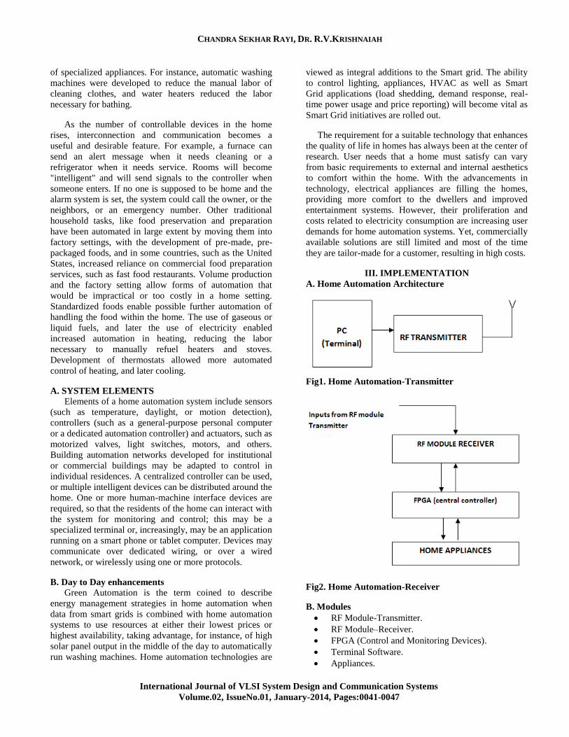
III. IMPLEMENTATION
A. Home Automation Architecture
Fig1. Home Automation-Transmitter
Fig2. Home Automation-Receiver
B. Modules
RF Module-Transmitter.
RF Module–Receiver.
FPGA (Control and Monitoring Devices).
Terminal Software.
Appliances.

SOC Implementation of Home Automation System based on RF Module
International Journal of VLSI System Design and Communication Systems
Volume.02, IssueNo.01, January-2014, Pages:0041-0047
1. RF Module-Transmitter - Receiver
An RF module (radio frequency module) is a (usually)
small electronic circuit used to transmit and/or receive
radio signals on one of a number of carrier frequencies. RF
modules are widely used in electronic design owing to the
difficulty of designing radio circuitry. Good electronic
radio design is notoriously complex because of the
sensitivity of radio circuits and the accuracy of components
and layouts required achieving operation on a specific
frequency. Design engineers will design a circuit for an
application which requires radio communication and then
"drop in" a radio module rather than attempt a discrete
design, saving time and money on development. RF
modules are most often used in medium and low volume
products for consumer applications such as garage door
openers, wireless alarm systems, industrial remote
controls, smart sensor applications, and wireless home
automation systems. They are often used to replace older
infra red radio communication designs as they have the
advantage of not requiring line-of-sight operation.
Module Application: Module has two modes, communic-
ation mode and configure mode, it is determined by the
status of CONFIG pin when power on:
CONFIG=LOW. It enter communication mode for data
transmission.
CONFIG=HIGH. It enter configure mode to setup work
parameters.
2. Communication mode
If CONFIG pin is low when powering on, the module
will enter into communication mode. The module provides
RS232 connector to connect with PC or TLL level with
MCU directly.
Fig3. Communication Diagram
It can work properly with the default configuration
(default configure is 9600, 8N, 1. the module work
parameters can be set up via HM-TR setup tool. When the
serial data rate is below 9600bps HM-TR module supports
continuous Transmission and the maximum data stream
can reach 1000000bytes; however, the data transmitted
each time should not exceed 32bytes in high-speed
applications>9600bps. HM-TR module work in half-
duplex mode. When receiving 32 Bytes from the serial
port, it will send data out at once. If the data package
received is below 32 Bytes, the module will wait for about
30 ms and then send it. In order to send data immediately,
32 Bytes data per transmission is necessary. After each
transmission, HM-TR module will be switched to receiver
mode automatically. The switch time is about 5ms.
ENABLE pin is used to control the power consumption.
Once this pin is pulled down, the module will enter into
sleep mode immediately. Users can use this pin to control
the receiving duty circle.
3. Configuration mode
If the CONFIG pin is in high level when powering on, the
module will enter into configuration mode automatically.
In this mode the module communicates with the host in
fixed serial format 96008N.
Fig4. Configure mode connection
B. FPAG (Control and Monitoring Devices)
The number of control and monitoring devices attached
to the FPGA depend on the number of free input/output
ports available on the FPGA. Furthermore, the system can
be further expanded by cascading FPGAs or by
multiplexing data coming from different sensors. This
makes the system scalable. The devices connected to the
FPGA can use either a wired connection or a wireless one,
such as RF module or Infra-red. In this work wired
solutions were used, however, the interface can be easily
replaced by a wireless solution.
IV. TERMINAL SOFTWARE
Terminal is a simple serial port (COM) terminal
emulation program. It can be used for communication with
different devices such as modems, routers, embedded
microcontroller or FPGA devices, C systems, GSM
phones, GPS modules... It is very useful debugging tool for
serial communication applications.

CHANDRA SEKHAR RAYI, DR. R.V.KRISHNAIAH
International Journal of VLSI System Design and Communication Systems
Volume.02, IssueNo.01, January-2014, Pages:0041-0047
Fig5.
A. TCP/IP Remote Control
Terminal can also act like telnet server and listen on
selected TCP port. You can connect to it with any telnet
client program from another computer in network (or over
internet from different location) and see what's going on in
terminal and send commands etc. Implementing with
terminal emulator by sending the commands like a,b,c and
d.
For ex:
If send the command “a” it will send through wireless by
RF module transmitter.
And received by FPGA and RF module receiver and
results will displayed as “61”. That means ASCII value of
“a” is 61 so that what the command is passed by terminal
software is which is displayed in chipscope software.
Now by receiving the commands use to light on and off
or fan on and off like home appliances. This way by using
terminal through RF module doing the home automation
appliances. Here connected “a” with light1 accordingly
switches on and off. Likely all commands are connected to
remaining switches. By sending the “a” command light1 is
on and send another command “b” then light2 is on
position and send another command “c” then fan1 is on
again send the commands “a” it will show light1 off
position likely all command are resending it will take on
and off position.
V. SIMULATION RESULTS
Fig6.
VI. SYNTHESIS REPORT
Timing Summary:
---------------
Speed Grade: -5
Minimum period: 8.191ns (Maximum Frequency:
122.084MHz)
Minimum input arrival time before clock: 1.731ns
Maximum output required time after clock: 7.995ns
Maximum combinational path delay: 2.191ns
VII. CHIPSCOPE RESULTS
A. CHIPSCOPE PRO ANALYSIS
The Xilinx ChipScope tools package has several
modules that can be added to the VHDL design to capture
input and output directly from the FPGA hardware.
ChipScope Pro Core Generator: Provides full design
generation capability for the IBERT core. The user
chooses the MGTs and parameters governing the
design, and the Core Generator uses the Xilinx ISE
toolset to produce a configuration file.ChipScope.
Pro Analyzer: Provides device configuration, project
management, monitoring status and controlling
variables.
JTAG Scripting: JTAG scriptable command interface
makes it possible to interact with devices in a JTAG
chain from a Tcl shell .Tcl stands for Tool Command
Language. A Tcl shell is a shell program that is used

SOC Implementation of Home Automation System based on RF Module
International Journal of VLSI System Design and Communication Systems
Volume.02, IssueNo.01, January-2014, Pages:0041-0047
to run Tcl scripts. Tcl/JTAG requires the Tcl shell that
is included in the Xilinx ISE 8.1i tool installation.
The Chip Scope Pro Analyzer tool supports the following
download cables for communication between the PC and
the devices in the JTAG Boundary Scan chain:
Platform Cable USB
Parallel Cable IV
Parallel Cable III
MultiPRO (JTAG mode only)
Users can place the ICON, ILA cores (collectively called
the ChipScope Pro cores) into the design by generating the
cores with the ChipScope Pro Core Generator and
instantiating them into the HDL source code. The design is
then placed and routed using the Xilinx ISE
implementation tools. Next, the bit stream is downloaded
into the device under test and analysis of the design is done
with the ChipScope Pro Analyzer software.
Fig7. ChipScope Pro Systems
B. Implementation with FPGA by using RF Module
Transmitter and Receiver by Terminal in Chipscope
Simulation
First open Terminal command software and connect or
check for available com port. After connecting com port
click on connect command.
Fig8.
Fig9.
Now send the commands for
a= light_1=> it will sends the ASCII value as 61.
b =light_2 => it will sends the ASCII value as 62.
c= fan_1 => it will sends the ASCII value as 63.
d=fan_2 => it will sends the ASCII value as 64.
C. CHIPSCOPE RESULTS
Fig10.
Here I send the command “a” which is equals light_1
equals “on” position if u send command “a” again an it
will indication of off. Similarly command b, c and d
commands. You are going to see the light on and off in
FPGA BOARD.
CHANDRA SEKHAR RAYI, DR. R.V.KRISHNAIAH
International Journal of VLSI System Design and Communication Systems
Volume.02, IssueNo.01, January-2014, Pages:0041-0047
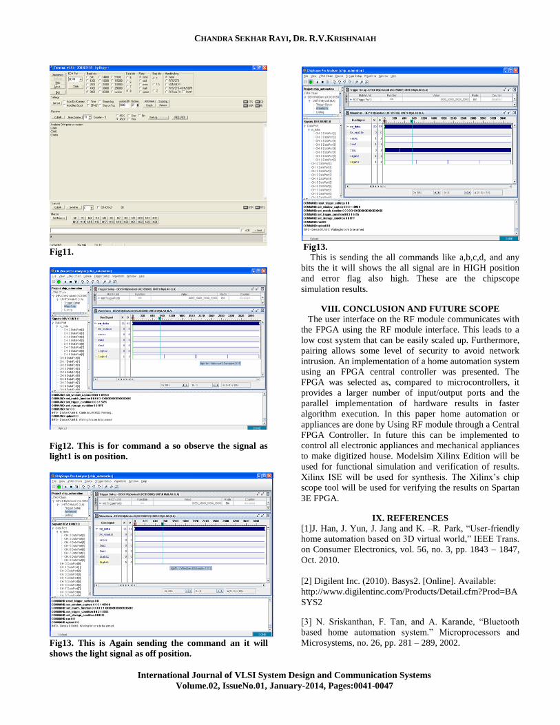
Fig11.
Fig12. This is for command a so observe the signal as
light1 is on position.
Fig13. This is Again sending the command an it will
shows the light signal as off position.
Fig13.
This is sending the all commands like a,b,c,d, and any
bits the it will shows the all signal are in HIGH position
and error flag also high. These are the chipscope
simulation results.
VIII. CONCLUSION AND FUTURE SCOPE
The user interface on the RF module communicates with
the FPGA using the RF module interface. This leads to a
low cost system that can be easily scaled up. Furthermore,
pairing allows some level of security to avoid network
intrusion. An implementation of a home automation system
using an FPGA central controller was presented. The
FPGA was selected as, compared to microcontrollers, it
provides a larger number of input/output ports and the
parallel implementation of hardware results in faster
algorithm execution. In this paper home automation or
appliances are done by Using RF module through a Central
FPGA Controller. In future this can be implemented to
control all electronic appliances and mechanical appliances
to make digitized house. Modelsim Xilinx Edition will be
used for functional simulation and verification of results.
Xilinx ISE will be used for synthesis. The Xilinx’s chip
scope tool will be used for verifying the results on Spartan
3E FPGA.
IX. REFERENCES
[1]J. Han, J. Yun, J. Jang and K. –R. Park, “User-friendly
home automation based on 3D virtual world,” IEEE Trans.
on Consumer Electronics, vol. 56, no. 3, pp. 1843 – 1847,
Oct. 2010.
[2] Digilent Inc. (2010). Basys2. [Online]. Available:
http://www.digilentinc.com/Products/Detail.cfm?Prod=BA
SYS2
[3] N. Sriskanthan, F. Tan, and A. Karande, “Bluetooth
based home automation system.” Microprocessors and
Microsystems, no. 26, pp. 281 – 289, 2002.

SOC Implementation of Home Automation System based on RF Module
International Journal of VLSI System Design and Communication Systems
Volume.02, IssueNo.01, January-2014, Pages:0041-0047
[4] G. Song, Z. Wei, W. Zhang and A. Song, “Design of a
networked monitoring system for home automation,” IEEE
Trans. on Consumer Electronics, vol. 53, no. 3, pp. 933 –
937, Aug. 2007.
[5] K. Gill, S. –H. Yang, F. Yao and X. Lu, “A ZigBee-
based home automation system,” IEEE Trans. on
Consumer Electronics, vol. 55, no. 2, pp. 422 – 430, May
2009.
[6] Y. –G. Ha, “Dynamic integration of Zigbee home
networks into home gateways using OSGi service
registry,” IEEE Trans. on Consumer Electronics, vol. 55,
no. 2, pp. 470 – 476, May 2009.
[7] X. Zhang, J. Sun and L. Zhou, “Development of an
Internet home automation system using Java and dynamic
DNS service,” in Proc. Of the 6th Int. Conf. on Parallel and
Distributed Computing, Applications and Technologies,
pp. 537 – 539, Dec. 2005.
Author’s Profile:
Chandra Sekhar Rayi, has
completed B.Tech (E.C.E) from
Kakinada Institute of Engineering &
Technology, pursuing M.Tech in
DRK institute of science and
technology, JNTUH, Hyderabad,
Andhra Pradesh, India. His main
research interest includes in
Electronics, Embedded & VLSI
Systems.
Dr.R.V.Krishnaiah, did M.Tech
(EIE) from NIT Waranagal, MTech
(CSE) form JNTU, Ph.D, from
JNTU Ananthapur, He has
memberships in professional bodies
MIE, MIETE, MISTE. His main
research interests include Image
Processing, Security systems,
Sensors, Intelligent Systems, Computer networks, Data
mining, Software Engineering, network protection and
security control. He has published many papers and
Editorial Member and Reviewer for some national and
international journals.