DESIGN AND IMPLEMENTAION OF A MICROCONTROLLER BASED HOME AUTOMATION SYSTEM USING AIWA REMOTE
16
DESIGN AND IMPLEMENTAION OF A MICROCONTROLLER BASED HOME AUTOMATION SYSTEM USING AIWA REMOTE Diarah, Reuben Samuel, Egbunne, Dickson .O, Aaron,Banji Adedayo 1 (Electrical and Information Engineering, College of Science and Engineering/ Landmark University Omu-Aran, Nigeria) [email protected] 2 (Electrical and Information Engineering, College of Science and Engineering/ Landmark University Omu-Aran, Nigeria) [email protected] 3 (Electrical and Information Engineering, College of Science and Engineering/ Landmark University Omu-Aran, Nigeria) [email protected] Abstract: - The need for a remote control system that can control domestic appliances and various lighting points and sockets has often been a concern for users. At times users find it inconvenient and time consuming to go around turning their appliances on or off each time there is power outage or each time they are leaving the house for work. It has also often led to damage of appliances due to the fact that an appliance was not turned off before leaving the house. The Objective of putting up this project, therefore, is to design equipment that can facilitate a convenient and easy way of controlling our domestic appliances, lighting points and sockets especially in powering them, without always going to appliances physically by ourselves. This objective will be accomplished using various components which include a Microcontroller (AT89C51) which acts as the backbone of the project together with other components. Keywords:- Microcontroller, infrared, relay, transmission, sensor I. INTRODUCTION The ease of putting our appliances, lighting points and sockets on or off has made it necessary to develop this system in order to control our appliances, lighting points and sockets from a central point using a remote control. The issues of always forgetting our appliances ON when leaving the house has often caused fire outbreak and explosion in homes and this is another reason that led to designing and construction of this project. One of the earliest examples of remote control was developed in 1893 by Nikola Tesla. With the invention of Relays previously in 1835 by Joseph Henry it became possible to use remote controls to drive other devices. This is because of the ability of the relays to serve as a switch
-
Upload
independent -
Category
Documents
-
view
0 -
download
0
Transcript of DESIGN AND IMPLEMENTAION OF A MICROCONTROLLER BASED HOME AUTOMATION SYSTEM USING AIWA REMOTE
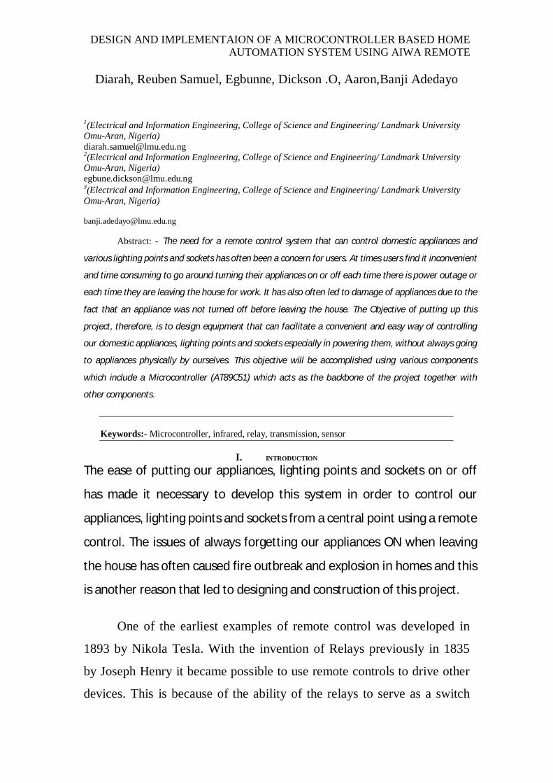
DESIGN AND IMPLEMENTAION OF A MICROCONTROLLER BASED HOME AUTOMATION SYSTEM USING AIWA REMOTE
Diarah, Reuben Samuel, Egbunne, Dickson .O, Aaron,Banji Adedayo
1(Electrical and Information Engineering, College of Science and Engineering/ Landmark University Omu-Aran, Nigeria) [email protected] 2(Electrical and Information Engineering, College of Science and Engineering/ Landmark University Omu-Aran, Nigeria) [email protected] 3(Electrical and Information Engineering, College of Science and Engineering/ Landmark University Omu-Aran, Nigeria)
Abstract: - The need for a remote control system that can control domestic appliances and
various lighting points and sockets has often been a concern for users. At times users find it inconvenient
and time consuming to go around turning their appliances on or off each time there is power outage or
each time they are leaving the house for work. It has also often led to damage of appliances due to the
fact that an appliance was not turned off before leaving the house. The Objective of putting up this
project, therefore, is to design equipment that can facilitate a convenient and easy way of controlling
our domestic appliances, lighting points and sockets especially in powering them, without always going
to appliances physically by ourselves. This objective will be accomplished using various components
which include a Microcontroller (AT89C51) which acts as the backbone of the project together with
other components.
Keywords:- Microcontroller, infrared, relay, transmission, sensor
I. INTRODUCTION
The ease of putting our appliances, lighting points and sockets on or off
has made it necessary to develop this system in order to control our
appliances, lighting points and sockets from a central point using a remote
control. The issues of always forgetting our appliances ON when leaving
the house has often caused fire outbreak and explosion in homes and this
is another reason that led to designing and construction of this project.
One of the earliest examples of remote control was developed in
1893 by Nikola Tesla. With the invention of Relays previously in 1835
by Joseph Henry it became possible to use remote controls to drive other
devices. This is because of the ability of the relays to serve as a switch
DESIGN AND IMPLEMENTAION OF A MICROCONTROLLER BASED HOME AUTOMATION SYSTEM USING AIWA REMOTE
that can control devices when energized by electricity. Again with the
invention of Integrated Circuits like 555 timers and Microcontrollers,
more functionality was added to the whole concept of Remote control.
The first remote, intended to control a television was developed by Zenith
Radio Corporation in the early 1950’s and made use of wire to connect to
the television set. The remote was unofficially called "Lazy Bones”. To
improve the cumbersome setup, a wireless remote control was created;
This Design consists of two sections which are;
The Transmitting side.
The receiving side.
The receiving side consists of a power supply section, a microcontroller
and Relays. It also houses the Infrared Receiving Sensor circuit. The
transmitting side is a smaller component which is a hand-held
component.. The transmission side also has a microcontroller which
coordinates the various button inputs. The last major component
contained in the transmitter side is the Infrared emitter/sender which
transmits signals received from the input buttons to the receiving side of
the system. This transmission is accomplished wirelessly through the
Infrared emitter/sender on the Transmitter section.
This Design can be used by anyone who uses domestic appliances
such as lights, fans, bells etc, Thus can be used to power any of these
appliances in homes, offices, industries, churches, conference rooms,
hospitals, etc at any desired time. This work will basically advance our
knowledge on the applications of remote control to control most of our
domestic appliances such as lighting points, fans, air-conditions, bells,
etc. at easy with the help of microcontroller
DESIGN AND IMPLEMENTAION OF A MICROCONTROLLER BASED HOME AUTOMATION SYSTEM USING AIWA REMOTE
THE PRINCIPLE BEHIND AN INFRARED REMOTE CONTROL: THE PROCESS
Pushing a button on the remote control sets in motion a series of events
that causes the controlled device to carry out a command.
The process works something like this:
1. You push the "volume up" button on your remote control, causing
it to touch the contact beneath it and complete the "volume up" circuit on
the circuit board. The integrated circuit detects this.
2. The integrated circuit sends the binary "volume up" command to
the LED at the front of the remote.
3. The LED sends out a series of light pulses that corresponds to the
binary "volume up" command.
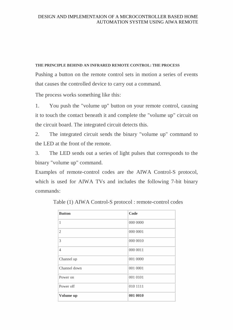
Examples of remote-control codes are the AIWA Control-S protocol,
which is used for AIWA TVs and includes the following 7-bit binary
commands:
Table (1) AIWA Control-S protocol : remote-control codes
Button Code
1 000 0000
2 000 0001
3 000 0010
4 000 0011
Channel up 001 0000
Channel down 001 0001
Power on 001 0101
Power off 010 1111
Volume up 001 0010
DESIGN AND IMPLEMENTAION OF A MICROCONTROLLER BASED HOME AUTOMATION SYSTEM USING AIWA REMOTE
Volume down 001 0011
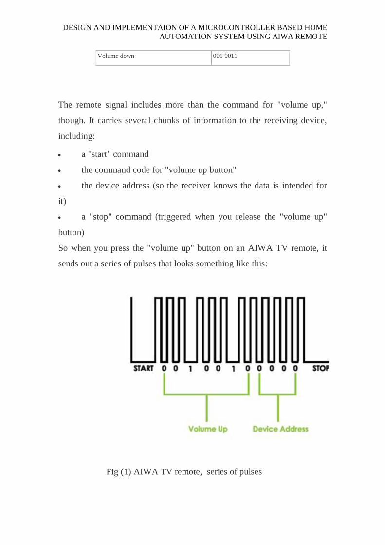
The remote signal includes more than the command for "volume up,"
though. It carries several chunks of information to the receiving device,
including:
a "start" command
the command code for "volume up button"
the device address (so the receiver knows the data is intended for
it)
a "stop" command (triggered when you release the "volume up"
button)
So when you press the "volume up" button on an AIWA TV remote, it
sends out a series of pulses that looks something like this:
Fig (1) AIWA TV remote, series of pulses
DESIGN AND IMPLEMENTAION OF A MICROCONTROLLER BASED HOME AUTOMATION SYSTEM USING AIWA REMOTE
When the infrared receiver on the circuit picks up the signal from the
remote and verifies from the address code that it's supposed to carry out
this command, it converts the light pulses back into the electrical signal
for 001 0010. It then passes this signal to the microcontroller, which will
use the information to switch the required device.
Infrared remote controls work well enough to have stuck over the years,
but they do have some limitations related to the nature of infrared light.
First, infrared remotes have a range of only about 30 feet (10 meters), and
they require line-of- sight. This means the infrared signal won't transmit
through walls or around corners -- you need a straight line to the device
you're trying to control. Also, infrared light is so ubiquitous that
interference can be a problem with IR remotes. Just a few everyday
infrared-light sources include sunlight, fluorescent bulbs and the human
body. To avoid interference caused by other sources of infrared light, the
infrared receiver on the circuit only responds to a particular wavelength
of infrared light, usually 980 nanometers. There are filters on the receiver
that block out light at other wavelengths. Still, sunlight can confuse the
receiver because it contains infrared light at the 980-nm wavelength. To
address this issue, the light from an IR remote control is typically
AIWA TV remotes use a space-coding method in which the
length of the spaces between pulses of light represents a one
or a zero.

DESIGN AND IMPLEMENTAION OF A MICROCONTROLLER BASED HOME AUTOMATION SYSTEM USING AIWA REMOTE
modulated to a frequency not present in sunlight, and the receiver only
responds to 980-nm light modulated to that frequency. The system doesn't
work perfectly, but it does cut down a great deal on interference.
While infrared remotes are the dominant technology in home-theatre
applications, there are other niche-specific remotes that work on radio
waves instead of light waves. If you have a garage-door opener, for
instance, you have an RF remote.
To allow a good communication using infrared, it is imperative to use a
key that can tell the receiver what is the real data transmitted and what is
fake.
The Remote control uses 36 KHz (or between 30 and 60 KHz) as its
frequency to transmit information.
Infrared light emitted by IR diodes is pulsated at 36 thousand times per
second, when transmitting logic level 1 and silence for 0.
A square wave of approximation 27µs (microsecond) injected at the base
of the transistor, can drive an infrared LED to transmit this pulsating light
wave.
Upon its presence, the commercial receiver will switch its output to high
level (+5V).
AIWA created the RC5 standard that uses fixed bit length and fixed
quantity of bits.
Each time you press a button at the AIWA remote control, it sends a train
of 14 bits, 1.728ms per bit, the whole train is repeated every 130ms if you
keep the button pressed. Each bit is sliced in two halves. The left and
right half has opposed levels.
If the bit to be transmitted is 1, its left side is zero while its right side is
one and vice versa. It means that the second half of the bit is actually the
same meaning of the bit to be transmitted.
DESIGN AND IMPLEMENTAION OF A MICROCONTROLLER BASED HOME AUTOMATION SYSTEM USING AIWA REMOTE
The AIWA remote are 32 pulses per each half of the bit, 64 pulses per bit.
So, a bit 0 to be transmitted it mean 32 square pulses of 27µs each, then
32 x 27µs of silence. The bit 1 is the opposite, 32 x 27µs of silence
followed by 32 square pulses of 27µs.
Our job here will be to decode the receiving of the waveform at the
demodulator output.
- The AIWA sends 14 bits in sequence.
- The first bit, 1is called AGC calibration. It is in ON level and serves to
calibrate the IR receivers Auto Gain Control or for START.
- The second bit, 2 is the CHECK bit, every time you press a key at the
remote, even pressing repeatedly the same key this flips state.
- The next 7 bits, 3 to 9 are used for COMMAND bits, or to send which
kind of work should be executed.
- The next 4 bits, 10 to 13 are used for DEVICE ADDRESS, or to
identify which kind of device should execute the COMMAND bits.
-The last bit, 14 is used for the STOP bit.
DESIGN AND IMPLEMENTAION OF A MICROCONTROLLER BASED HOME AUTOMATION SYSTEM USING AIWA REMOTE
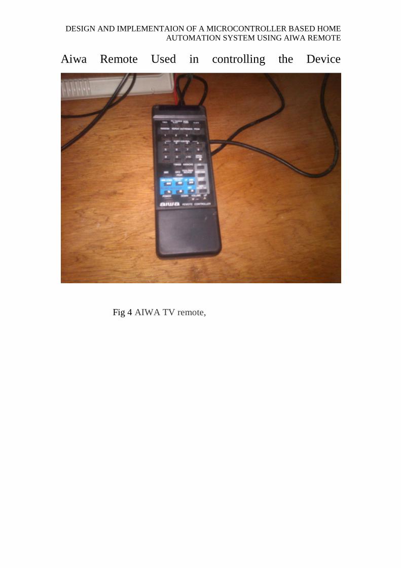
Aiwa Remote Used in controlling the Device
Fig 4 AIWA TV remote,
DESIGN AND IMPLEMENTAION OF A MICROCONTROLLER BASED HOME AUTOMATION SYSTEM USING AIWA REMOTE
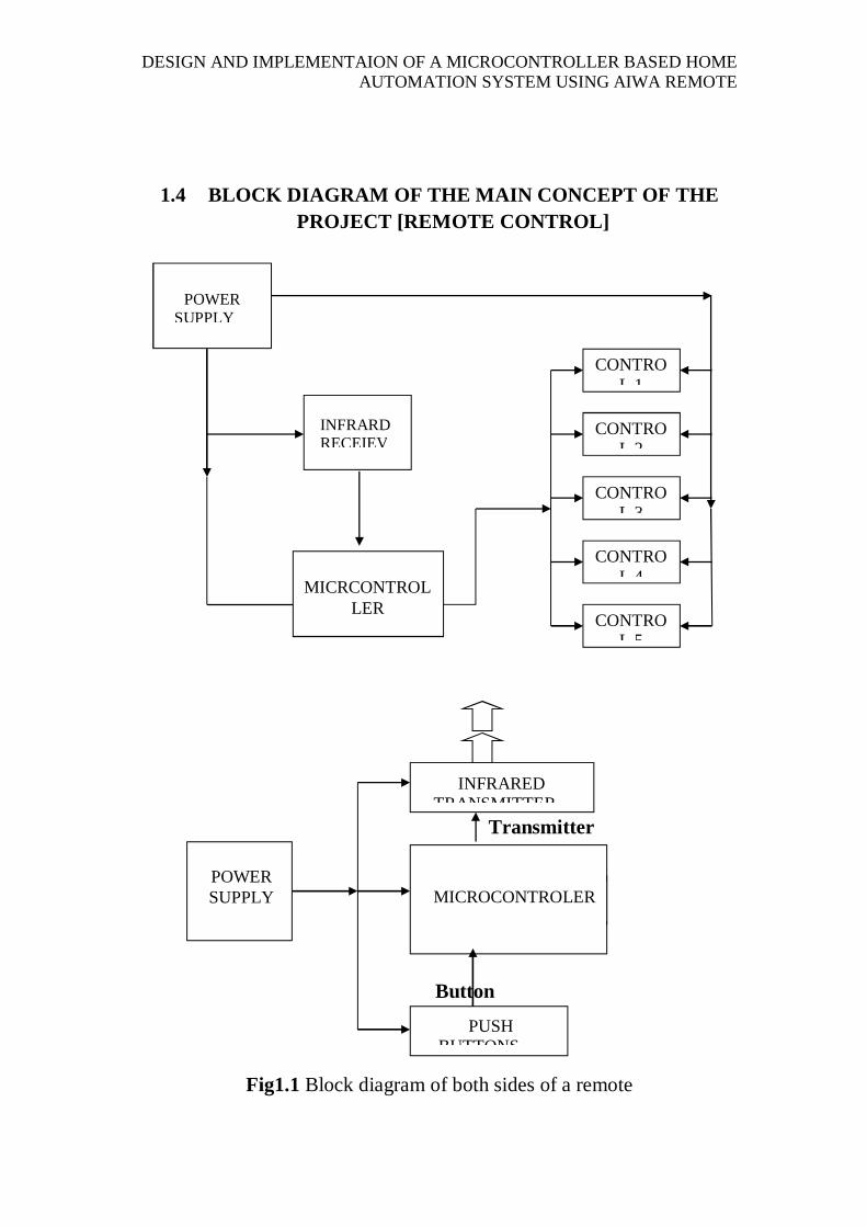
1.4 BLOCK DIAGRAM OF THE MAIN CONCEPT OF THE PROJECT [REMOTE CONTROL]
Transmitter
Button
Fig1.1 Block diagram of both sides of a remote
MICROCONTROLER
INFRARED TRANSMITTER
POWER SUPPLY
PUSH BUTTONS
INFRARD RECEIEV
POWER SUPPLY
MICRCONTROL
LER
CONTROL 1
CONTROL 2
CONTROL 3
CONTROL 4
CONTROL 5
DESIGN AND IMPLEMENTAION OF A MICROCONTROLLER BASED HOME AUTOMATION SYSTEM USING AIWA REMOTE
THE HARDWARE SUBSYSTEMS The design of the essential interfaces and sub sections that makes
the two sections of the project is treated here. There function and mode of
operation will be presented here.
The power supply design. Basically, it employs a 5V regulated power
supply that powers the microcontroller which needs nothing but a 5V and
the NPN transistors used. A 12V supply is also used in the design which
is meant to power a 12V relay.
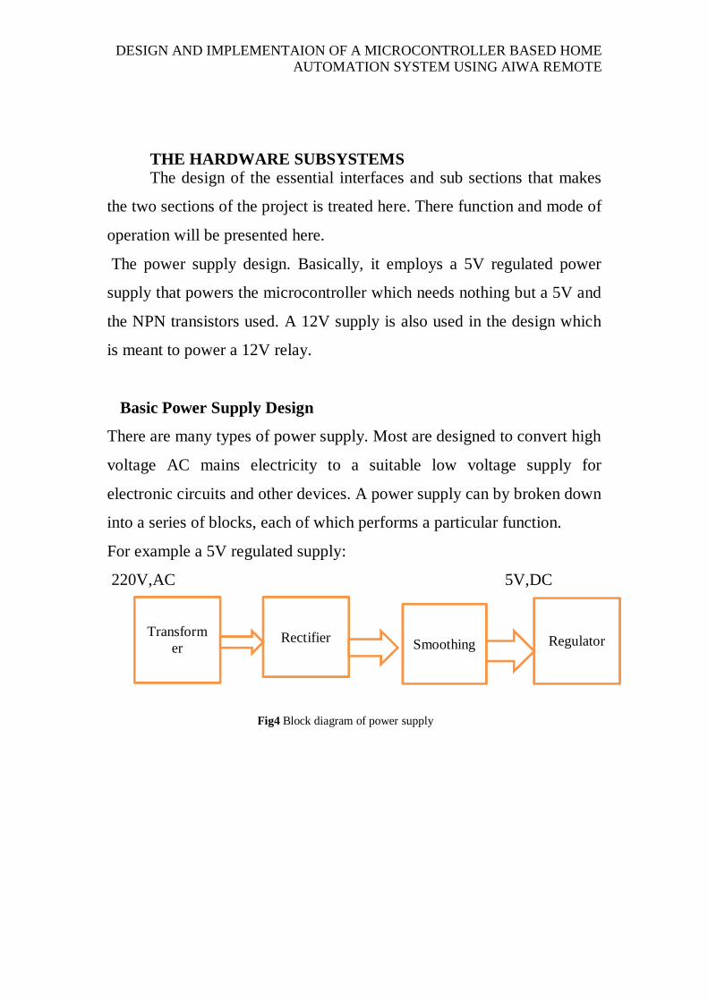
Basic Power Supply Design
There are many types of power supply. Most are designed to convert high
voltage AC mains electricity to a suitable low voltage supply for
electronic circuits and other devices. A power supply can by broken down
into a series of blocks, each of which performs a particular function.
For example a 5V regulated supply:
220V,AC 5V,DC
Fig4 Block diagram of power supply
Transform
er
Rectifier Smoothing Regulator
DESIGN AND IMPLEMENTAION OF A MICROCONTROLLER BASED HOME AUTOMATION SYSTEM USING AIWA REMOTE
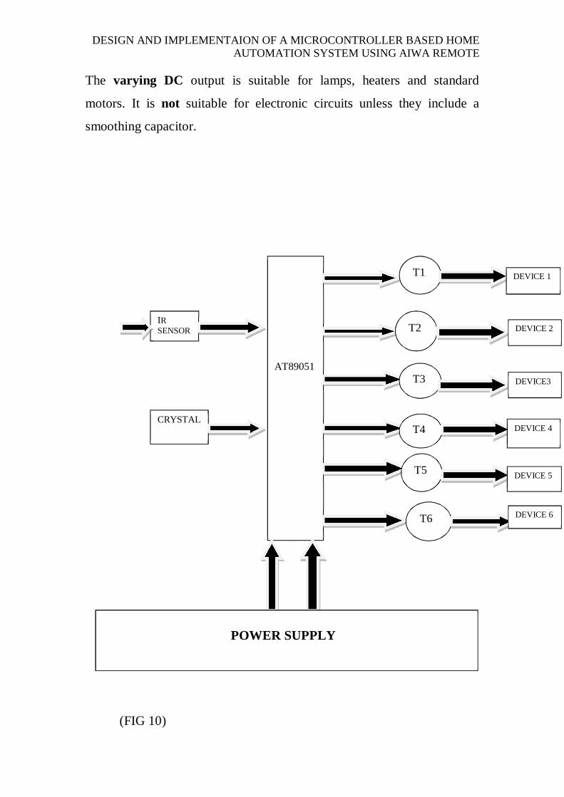
The varying DC output is suitable for lamps, heaters and standard
motors. It is not suitable for electronic circuits unless they include a
smoothing capacitor.
(FIG 10)
AT89051
T1
T2
T3
T4
T6
T5
IR SENSORR
CRYSTAL
DEVICE 1
DEVICE 2
DEVICE3
DEVICE 4
DEVICE 5
DEVICE 6
POWER SUPPLY
DESIGN AND IMPLEMENTAION OF A MICROCONTROLLER BASED HOME AUTOMATION SYSTEM USING AIWA REMOTE
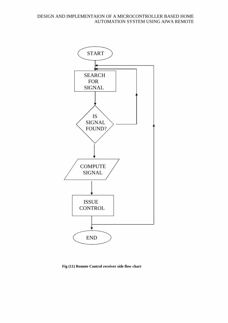
Fig (11) Remote Control receiver side flow chart
END
COMPUTE SIGNAL
ISSUE CONTROL
IS SIGNAL FOUND?
SEARCH FOR SIGNAL
START
DESIGN AND IMPLEMENTAION OF A MICROCONTROLLER BASED HOME AUTOMATION SYSTEM USING AIWA REMOTE
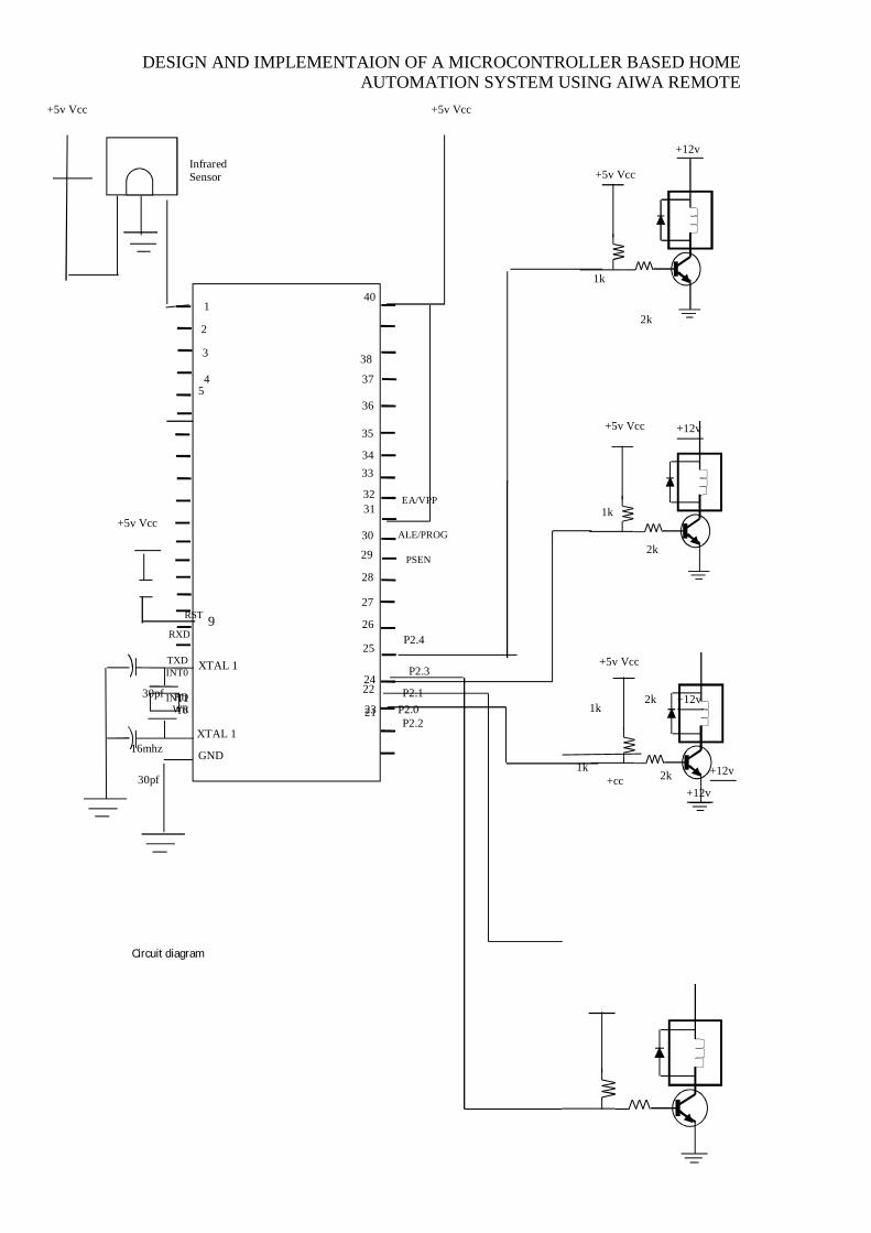
Circuit diagram
XTAL 1
XTAL 1
GND
31
40
+5v Vcc
+5v Vcc
+5v Vcc
+5v Vcc
+cc
1
P2.4
P2.3
P2.2
P2.1 P2.0 21
22
23
24
25
26
27
28
29
30
32
33 34
35
36
37
38
30pf
30pf
16mhz
1k
1k
1k
1k 2k
2k
2k
2k
Infrared Sensor
+5v Vcc
+12v
+12v
+12v
+12v
+12v
EA/VPP
ALE/PROG
PSEN
RST
RXD
TXD INT0
INT1 T0 T1
WR RD
+5v Vcc
9
2
3
4 5
DESIGN AND IMPLEMENTAION OF A MICROCONTROLLER BASED HOME AUTOMATION SYSTEM USING AIWA REMOTE
14
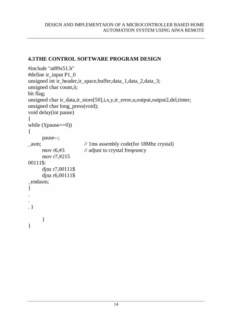
4.3 THE CONTROL SOFTWARE PROGRAM DESIGN
#include "at89x51.h" #define ir_input P1_0 unsigned int ir_header,ir_space,buffer,data_1,data_2,data_3; unsigned char count,ii; bit flag; unsigned char ir_data,ir_store[50],i,x,y,ir_error,u,output,output2,del,timer; unsigned char long_press(void); void delay(int pause) { while (!(pause==0)) { pause--; _asm; // 1ms assembly code(for 18Mhz crystal) mov r6,#3 // adjust to crystal freqeuncy mov r7,#215 00111$: djnz r7,00111$ djnz r6,00111$ _endasm; } . . . } } }
DESIGN AND IMPLEMENTAION OF A MICROCONTROLLER BASED HOME AUTOMATION SYSTEM USING AIWA REMOTE
15
II. CONCLUSIONS
Home automation was made possible by this design using the concept of
microcontroller and the application of infrared transmission. the design and
implementation of this project makes life easy, thus controlling our home
appliances such as fans, lighting points and sockets with just a press on a button.
ACKNOWLEDGMENT
We wish to thank the management of landmark University Omu-Aran for their effort in providing the needed support for this Design, may the Almighty God richly them.
REFERENCES [1] Microcontroller Based Security system with Intruder Position IOSR Journal of Electrical and Electronics
Engineering (IOSR-JEEE) e-1ssN:227-1676, P-ISSN: 2320-3331, Volume 9 ISSUE 1(Jan 2014) pp 01-08.
[2] Microcontroller Based Security system with Intruder Position IOSR Journal of Electrical and Electronics
Engineering (IOSR-JEEE) e-IssN:227-1676, P-ISSN: 2320-3331, Volume 9 ISSUE 1(Jan 2014) pp 09-17
[3] Implementation of User Interface for Microcontroller Trainer International Journal of Information Technology Convergence and Services (IJITCS) Vol.1, No.4, August 2011 pp 53 (4). Belone Schilling, Electronic Circuits: Discrete and Integrated, McGraw-Hill, New York,1979.
(5). B.L Theraja and A.K Theraja, A Textbook on Electrical Technology, 2003, 23rd Edition, Pp 1887 – Pp
1888.
(6). Paul Horowitz and Windfield Hill, The Art of Electronics, 1989, 2nd Edition, Pp 7- Pp 8, Pp 55 – Pp 58,
Pp 614 –Pp 622.
(7). Atmel Corporation Data Sheet on AT89C51, 0285D-B-12/97
(8). NTE Electronics Inc., ECG Data Book, January 2002, 10th Edition.
(9). Giorgio Rizzoni, Principles of Electrical Engineering, 2003, 3rd Edition,
DESIGN AND IMPLEMENTAION OF A MICROCONTROLLER BASED HOME AUTOMATION SYSTEM USING AIWA REMOTE
16
(10). Ronald .J Tocci, Digital Systems, Arentice – Hall. Inc. USA.
(11).Wikipedia Encylopedia October 2013
(13).Atmel 89c51 Manual (PDF)
Atmel Corporation, 2013
(14). www.kpsec.freeuk.com
Power supplies by John Hewes