Design and Implementation of Smart Home System Using ...
10
Vol. 7. No. 1, March 2019 33 Design and Implementation of Smart Home System Using Internet of Things Davies E. I. & Anireh, V.I.E. (PhD) Department of Computer Science Rivers State University Port Harcourt, Nigeria E-mail: [email protected], [email protected]. ABSTRACT Smart home is the automation and control of Electronic appliances and light energy systems found in the home. In this presentation, a smart home system was designed and implemented using Internet of Things (IoT). The Rapid Application Development methodology was chosen to take advantage of its robustness in handling changes and speed in developing systems. The system consist of three sub systems the Remote System, Simulated System and Cloud System. The Remote System (mobile system or remote control device) consists of an alert system to notify the user of an event that needs attention. The mobile system is a messaging service used to send and receive data messages from the Application Program Interface. The simulated system consists of the following; a Set of trusted encrypted keys used to checkmate commands and data received from the data layer, a notifier for visual alert to the users, a messaging service to notify other systems for changes in order to receive command and data, triggers to enable automated action that may proceed from any events. The cloud system consists of all the remote business logic. The system developed worked well and its evaluation showed that it was cost effective for at least a middle class group. Keywords: Smart Home, Internet of Things, Cloud System, Remote System, Simulated Systems 1. INTRODUCTION The concept of home automation has been around since the late 1970s though with the advancement in technology and services, people’s expectations of what a home should be or how the services should be provided for and accessed at home continues to change. Smart Home describes a residence that has appliances, lighting, heating, air conditioning, televisions, computers, entertainment (audio and video systems), security, and camera systems that can communicate with one another and can be controlled remotely by a time schedule, from any room in the home, as well as remotely from any location in the world by phone or internet facility.(Edmonds & Chandler, 2008). Article Progress Time Stamps Article Type: Research Article Manuscript Received: 17 th Jan. 2019 Review Type: Blind Final Acceptance:: 16 th Feb, 2019 Article DOI: dx.doi.org/10.22624/AIMS/DIGITAL/V7N1P4 Article Citation Format Davies E. I. & Anireh, V.I.E. (2019): Design and Implementation of Smart Home System Using Internet of Things Journal of Digital Innovations & Contemp Res. In Sc., Eng & Tech. Vol. 7, No. 1. Pp 33-42
-
Upload
khangminh22 -
Category
Documents
-
view
3 -
download
0
Transcript of Design and Implementation of Smart Home System Using ...

Vol. 7. No. 1, March 2019
33
Design and Implementation of Smart Home System Using Internet of Things
Davies E. I. & Anireh, V.I.E. (PhD) Department of Computer Science
Rivers State University Port Harcourt, Nigeria
E-mail: [email protected], [email protected].
ABSTRACT Smart home is the automation and control of Electronic appliances and light energy systems found in the home. In this presentation, a smart home system was designed and implemented using Internet of Things (IoT). The Rapid Application Development methodology was chosen to take advantage of its robustness in handling changes and speed in developing systems. The system consist of three sub systems the Remote System, Simulated System and Cloud System. The Remote System (mobile system or remote control device) consists of an alert system to notify the user of an event that needs attention. The mobile system is a messaging service used to send and receive data messages from the Application Program Interface. The simulated system consists of the following; a Set of trusted encrypted keys used to checkmate commands and data received from the data layer, a notifier for visual alert to the users, a messaging service to notify other systems for changes in order to receive command and data, triggers to enable automated action that may proceed from any events. The cloud system consists of all the remote business logic. The system developed worked well and its evaluation showed that it was cost effective for at least a middle class group. Keywords: Smart Home, Internet of Things, Cloud System, Remote System, Simulated Systems
1. INTRODUCTION
The concept of home automation has been around since the late 1970s though with the advancement in technology and services, people’s expectations of what a home should be or how the services should be provided for and accessed at home continues to change. Smart Home describes a residence that has appliances, lighting, heating, air conditioning, televisions, computers, entertainment (audio and video systems), security, and camera systems that can communicate with one another and can be controlled remotely by a time schedule, from any room in the home, as well as remotely from any location in the world by phone or internet facility.(Edmonds & Chandler, 2008).
Article Progress Time Stamps
Article Type: Research Article Manuscript Received: 17th Jan. 2019
Review Type: Blind Final Acceptance:: 16th Feb, 2019
Article DOI: dx.doi.org/10.22624/AIMS/DIGITAL/V7N1P4
Article Citation Format Davies E. I. & Anireh, V.I.E. (2019): Design and Implementation of
Smart Home System Using Internet of Things Journal of Digital Innovations & Contemp Res. In Sc., Eng &
Tech. Vol. 7, No. 1. Pp 33-42

Vol. 7. No. 1, March 2019
34
Today, mobile phones are used as clocks, calendars or controllers instead of just for making and receiving calls. With the help of the internet, a mobile device can be used to implement a smart home by controlling devices and getting alerts. The Internet of Things (IoT) is a system of inter-related computing devices, mechanical and digital machines, objects, animals or people that are provided with unique identifiers and the ability to transfer data over a network without requiring human to human or human to computer interaction, (Wadhwa & Puri, 2016). Now and over time efficient, convenient, and safe ways to access homes will be provided for. Irrespective of the change in user expectations, advancement of technology, or change of time, the role of a home automation system has remained the same. Throughout the late 1990s and early 2000s, smart technologies has emerged, with gadgets and devices becoming more and more common, and more affordable. 2. RELATED WORKS ECHO IV and the Kitchen Computer developed in the late 1960s were about the first smart devices though they were not commercially sold. The devices could compute shopping lists, control the home temperature and turn appliances on or off and the Kitchen Computer, developed a year later, could also store recipes. In 1991, GERONTECHNOLOGY- a combination of gerontology and technology was developed to make the lives of senior citizens easier and better. Later advances in technology and services grew in bounds, and a tele-monitoring system based on a Short Message Service (SMS), to remotely monitor the long-term mobility levels of elderly people in their natural environment were introduced. To measure the mobility of subjects, an accelerometer-based portable unit are worn by each monitored subject. An Internet-based monitoring and control of fuzzy controlled inverter for air conditioning system was developed by Yen-Shin Lai in 2002. The system consists of client/server, programmable logic controller, D/A modules, inverters, induction motors and the temperature sensing modules. The client accepts the command from the user and can also access the database created in server, using Internet Explorer (IE) Browser. The server performs function of fuzzy logic control, communication interface between server and Programmable Logic Controller(PLC), and receiving command from client. Furthermore, the server also creates a database of the sensed temperature, speed of inverter-controlled motor drives, and reference command A home security system was implemented by Alheraish; 2004, by means of GSM cellular communication network using microcontroller 89X52 and Sony Ericsson GM-47 GSM module. This system enables far end user through SMS facility to monitor the state of home door, provide password facility for key based door lock and control home lighting system. A Java based home automation system via World Wide Web (WWW) was developed in 2004 by Al-Ali and Al-Rousan. The home appliances were controlled from ports of embedded system board connected to PC based server at home. The system is scalable and allows multi-vendor appliances to be added with no major changes to its core. Password protection is used to block unauthorized users from accessing the appliances at home. If the Internet connection is down or the server is not up, the embedded system board still can control and operate the appliances locally. (Al-Ali, 2004) In the case of (Cliodhna, 2006), the portable unit, houses the Analog Devices ADuC812S microcontroller board, Falcon A2D-1 GSM modem, and a battery-based power supply. Two integrated accelerometers are connected to the portable unit through the analog inputs of the microcontroller. Mobility level summaries are transmitted hourly, as an SMS message, directly from the portable unit to a remote server for long-term analysis. Each subject’s mobility levels are monitored using custom-designed mobility alert software, and the appropriate medical personnel are alerted by SMS if the subject’s mobility levels decrease.

Vol. 7. No. 1, March 2019
35
A system for early diagnosis of hypertension and other chronic diseases was proposed by(Jiang, 2008). The proposed design consists of three main parts: a wrist Blood Pressure (BP) measurement unit, a server unit and a terminal unit. Blood Pressure is detected using data acquired by sensors intelligently using DSP microchip. The data is then transmitted to the remote server unit located at Community Healthcare Centers/Points (CHC/P) by using Short Messaging Service (SMS), and notification information is sent to the terminal unit to inform users if patient’s BP is abnormal). Chen Peijiang and Jiang Xuehua, in 2008, came up with a system in which they described a remote monitoring system based on SMS of GSM. The system includes two parts: the monitoring centre and the remote monitoring station. A home automation system based on Wireless Sensor Networks (WSNs) and General Packet Radio Service (GPRS) was proposed by (Jianshe, 2012) that allowed its users to control equipment in their home, and collect data about a device’s status and weather conditions at home through their mobile devices. The authors’ custom-made the application for China, as users receive information about home intrusions and fire through the Chinese Instant Message Mobile Service. Unlike other GPRS-based home automations, the proposed system uses an embedded system-based central controller. Current trends in home automation include remote mobile control, automated lights, automated thermostat adjustment, scheduling appliances, mobile/email/text notifications, and remote video surveillance (Hendricks, 2014). A home gateway system for interconnecting home network consisting of IEEE 1394 AV network and X10 power line home automation network with Internet was proposed by Saito in 2009. This provided remote access functions from Internet for digital Audio Visual(AV) appliances like Digital Video Camera, Digital VCR connected to IEEE 1394 network and home appliances like TV, desk lamp, electric fan connected to X10 controller. (Mayur et al., 2015) An iOS-based home automation security system using General Packet Radio Service (GPRS) was developed by S.R. Das. The proposed system uses the client/server model for communication. The authors develop an iOS application that runs on a user’s mobile phone and acts as the client, and the cloud to which the home devices are connected acts as the server. The authors use video cameras, microphones, and motion sensors for providing security at home. When a motion sensor is triggered, the video cameras in the vicinity start to record. A user can view these live feeds on a mobile device through GPRS. The proposed system can also be accessed using a web browser, (Arun, 2017). Despite these success recorded in home automation systems, John J. Greichen (1992) discussed challenges faced to include high manufacturing costs, high development costs, high installation costs, additional service and support costs, lack of home automation standards, consumer unfamiliarity with technology, and complex user interfaces. Today’s Smart Homes are more about security, alerting us about unauthorized intrusion, living greener, sustainability, and they help to ensure that our homes reduce unnecessary energy waste. 3. MATERIALS AND METHOD The methodology adopted was Rapid Application Development (RAD). The RAD model, fig 1. is a type of incremental model in which, the components or functions are developed in parallel as if they were mini projects. In this model, once initial requirement analysis and specification are concluded, design, coding and unit testing gets out the first prototype. The developments are time boxed, delivered and then assembled into a working prototype.

Vol. 7. No. 1, March 2019
36
It has the major advantage of having a reduced development time, increases reusability of components and integration from the very beginning that solves many integration issues.
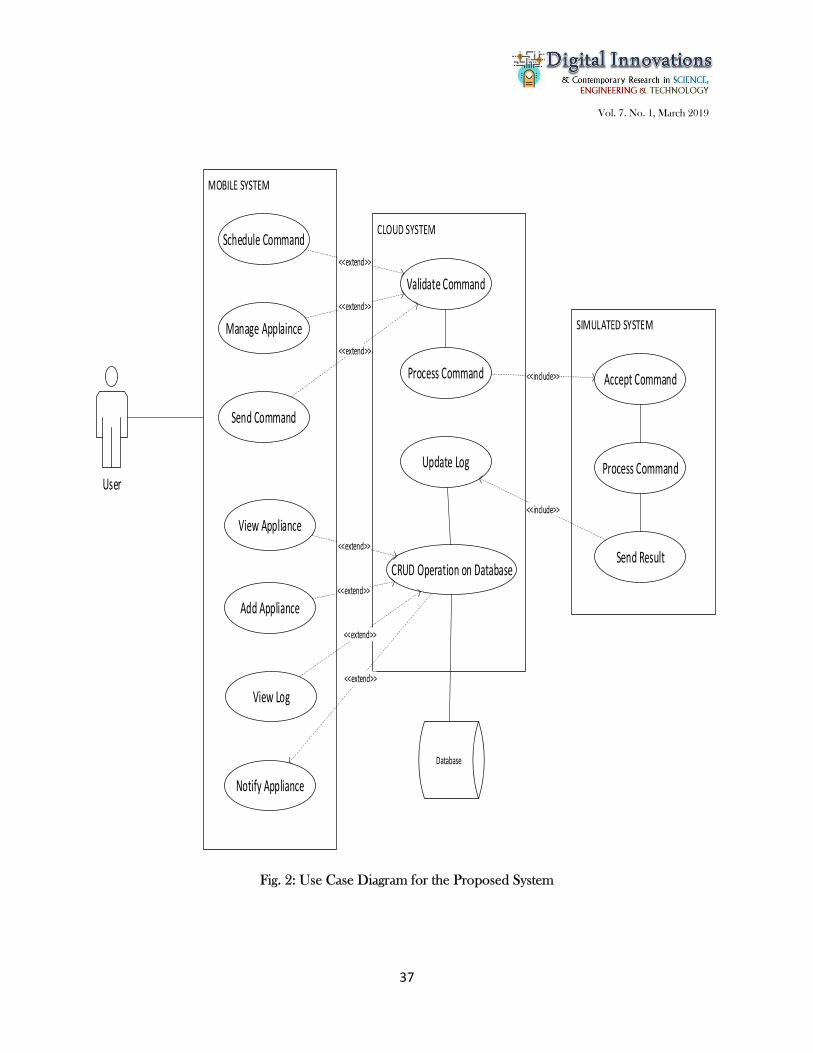
Fig. 1: The RAD Model The Use Case Diagram in fig. 2 describes how the proposed system functions and the relationship between the inter-relational operation of the modules. It shows that a remote user using the mobile system can view appliances, manage appliances, schedule a command, view log of the system, add appliances and that system notify the remote user of whatever action it takes. The mobile system (Remote System or Remote Control Device) consists of an alert system which is used to notify the user of an event that needs attention. It has a dashboard which consisting of all the electronics appliances in the smart home. It has a messaging service used to notify other systems about an event that needs to be taken care of and a message receiver that will be used to received data from the Application Program Interface. It also contains the front-end security since it is the only access to the system from the user. It interfaces with the cloud system using http protocol. The simulated system consists of the following; A Set of trusted encrypted keys used to checkmate commands and data received from the data layer. A notifier for visual alert to the users. A messaging service to notify other system for changes, receiver to receive command and data, triggers to enable automated action that may be lead from any events. The cloud system which links the database directly, consists of all the remote business logic, were operations such as create, read, update, and delete can be implemented.
Vol. 7. No. 1, March 2019
37
Fig. 2: Use Case Diagram for the Proposed System
Schedule Command
Manage Applaince
Send Command
View Appliance
Add Appliance
View Log
Notify Appliance
Validate Command
Process Command
Update Log
CRUD Operation on Database
Accept Command
Process Command
Send Result
User
<<extend>>
<<extend>>
<<extend>>
<<extend>>
<<extend>>
<<extend>>
<<include>>
<<include>>
Database
<<extend>>

Vol. 7. No. 1, March 2019
38
The class diagram fig 3. uses the first row to denote the name of the class and the second row to denote the properties while the third row denotes the functions. As shown in the diagram, the Signing class is where a user can either sign up, recover lost password or sign into the system. The registration class has Email, Password, FirstName, and Phone as properties and register, login and forgot as method. A user can sign in and get to the menu class where he can perform all the actions in system such as View, or Manage Appliances and manage Command, View log. Manage Appliance Class helps to delete or update an appliance, whereas, View Appliance class displays the name, status of the various appliances. Manage Appliance Class helps to delete or update an appliance, whereas, View Appliance class displays the name, status of the various appliances. The log class helps keep tab on every activity with a time stamp on the log list.
Fig. 3: Class Diagram for Proposed System

Vol. 7. No. 1, March 2019
39
The data flow model (Figure 4) shows how data flows in the system. The system uses JavaScript Object Notation(JSON) as its primary data. Data flows from the Mobile system into the Command sender (Command to be sent) which is then transferred to the command receiver of the cloud system using http post request to the web server which receives the command, and sends the command to the database to be stored. The command is then converted into an action, then sends it to its action sender which in turn routes it to the simulated system (micro controller) action receiver. It then receives and performs the action, sending its new status to the status changer, which notifies the cloud system of the change, the cloud system updates the database, then sends the new status to the status receiver of the mobile system which now notifies the user of the result of the action and the new status of the system.
Fig.4 Data Flow Diagram of the Proposed System
Database
MobileCommand
SenderSend Command
Cloud system
Command Reciever
Status Reciever Status Sender Send Status
Received Status
Status Changer System Notifier
Micro Controller
Send Latest Status
Received Latest Status
Action SenderSend Action
Action RecieverReceived Action
Retrieve Status and CommandStored Status and Command
Received Command

Vol. 7. No. 1, March 2019
40
Fig. 5: Architecture of the Proposed System 4. RESULTS The entries in Table 1 show the comparative results of task execution per second using Remote Control, manual and Non-smart system observed over a period of time. It is clearly observed that when performing advanced, complex and scheduled tasks, the new system is better because of the encapsulation (a process of wrapping code and data together into a single unit to control/restrict access to both data and function from other objects) of most of the functions, whereas, when performing basic tasks, the non-smart system (existing system) is better, due to the fact that all activities are physically operated there is no latency with regards to networks.
CLOUD SYSTEMREMOTE SYSTEM DATABASE
MICRO PROCESSOR
COFEE MAKER
MICROWAVE
REFRIGERATOR
AIR CONDITIONER
RADIO
TELEVISION
LIGHT
Vol. 7. No. 1, March 2019
41
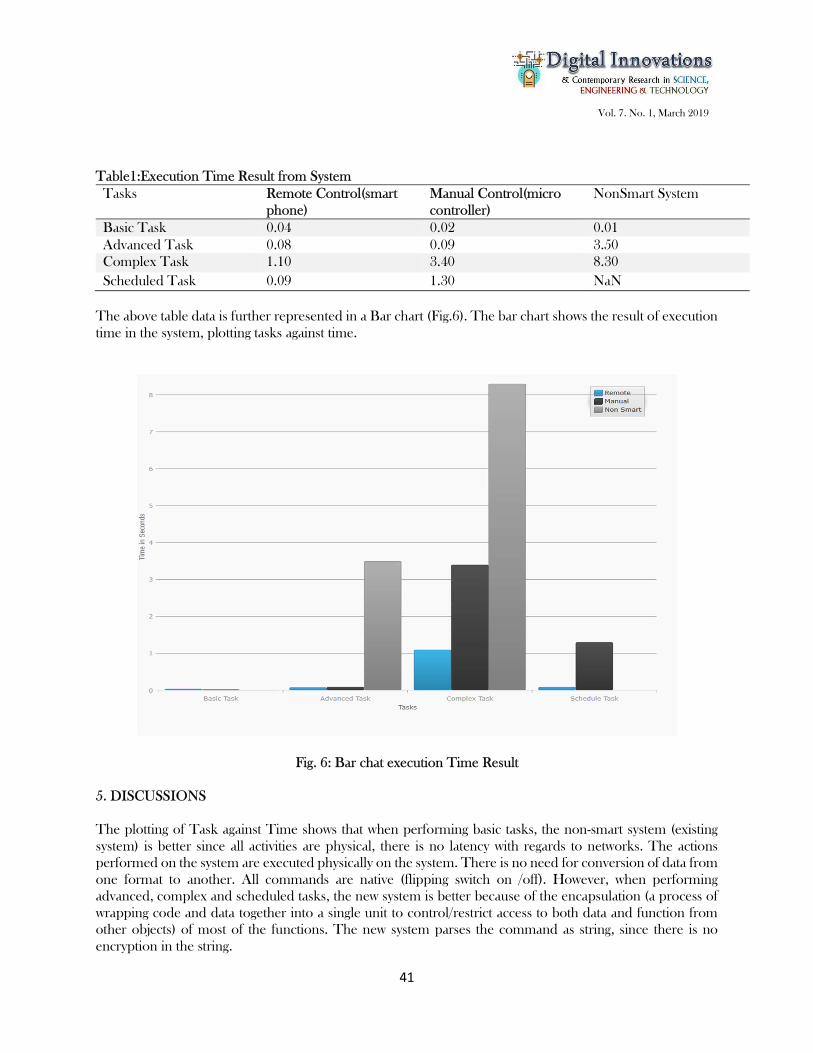
Table1:Execution Time Result from System Tasks Remote Control(smart
phone) Manual Control(micro controller)
NonSmart System
Basic Task 0.04 0.02 0.01 Advanced Task 0.08 0.09 3.50 Complex Task 1.10 3.40 8.30 Scheduled Task 0.09 1.30 NaN
The above table data is further represented in a Bar chart (Fig.6). The bar chart shows the result of execution time in the system, plotting tasks against time.
Fig. 6: Bar chat execution Time Result 5. DISCUSSIONS The plotting of Task against Time shows that when performing basic tasks, the non-smart system (existing system) is better since all activities are physical, there is no latency with regards to networks. The actions performed on the system are executed physically on the system. There is no need for conversion of data from one format to another. All commands are native (flipping switch on /off). However, when performing advanced, complex and scheduled tasks, the new system is better because of the encapsulation (a process of wrapping code and data together into a single unit to control/restrict access to both data and function from other objects) of most of the functions. The new system parses the command as string, since there is no encryption in the string.

Vol. 7. No. 1, March 2019
42
After parsing the string, the system then executes the command. This reduces the execution time as compared to the default system provided by the manufacturers. There is also an improvement in using the remote system (mobile device) as compared to accessing the smart appliance directly. It also shows that the existing system cannot schedule tasks due to the different manufacturers. The new system performs the scheduling at the software level, as depicted in Figure 3, particularly the command manager class, therefore, a timer is set to invoke the function at the scheduled time. 6. CONCLUSION Most recent devices adopt the Android capability; therefore, integrating them into a home automation system will be simple and seamless. The Internet of Things (IoT) has brought about the possibility of collapsing all objects on the surface of the earth under one umbrella, making inter-connectivity and communication a possibility for data sharing. This has made smart home automation a possibility, thereby reducing human interference to the barest minimum. Time management, financial management and energy efficiency and conservation has been maximised by home automation. REFERENCES
1. Al-Ali, A., and Al-Rousan, M.A. (2004). Java-based Home Automation System. IEEE Transactions on Consumer Electronics, 50, 498-504.
2. Alheraish, A. (2004). Design and implementation of home automation system, IEEE Transactions on Consumer Electronics, 50(4), Page 1087-1092
3. Arun C. J. (2017). Improving Smart Home Security; Integrating Logical Sensing into Smart Home, 17(13), 4269-4286
4. Chen Peijiang and Jiang Xuehua, (2008), PACIIA '08 Proceedings of the 2008 IEEE Pacific-Asia Workshop on Computational Intelligence and Industrial Application – 1, 678-681
5. Edmonds,&Chandler,N.(2008).HowSmartHomesWork. https://home.howstuffworks.com/smart-home7.htm
6. Greichen, J.J. (1992). Value Based Home Automation for Today's Market. IEEE Transactions on Consumer Electronics, 38(3): XXXIV - XXXVIII,
7. Hendricks, D. (2014). The History of Smart Homes. (S. Viscusi, Editor) http://www.iotevolutionworld.com/m2m/articles/376816-history-smart-homes.htm.
8. Jianshe J. X. Y. (2012). The Application Design of Smart Home Model System. The 2nd International Conference on Computer Application and System Modelling.
9. Jiang J. Z. Y. (2008). Design of wireless mobile monitoring of blood pressure for underserved in China by using Short Messaging Service. IEEE Xplore Digital Library.
10. Mayur D, et al (2015) Biomedical Data Transmission System with Central Monitoring, International Journal of Scientific Research and Engineering Studies (IJSRES),2(2),92.
11. Wadhwa, P., & Puri, A. (2016). Internet of Things: Challenges and impact. International Journal of Engineering Research and General Science, IV.
12. Yen-Shin Lai et al, (2002), Internet-based monitoring and control of fuzzy-controlled inverter system, IEEE 28th Annual Conference of the Industrial Electronics Society, IECON 02
View publication statsView publication stats