ATHABASCA UNIVERSITY Smart Home and Garden System ...
95
ATHABASCA UNIVERSITY Smart Home and Garden System BY GUANG YEW A project submitted in partial fulfillment Of the requirements for the degree of MASTER OF SCIENCE in INFORMATION SYSTEMS Athabasca, Alberta April 2017 © Guang Yew, 2017
-
Upload
khangminh22 -
Category
Documents
-
view
2 -
download
0
Transcript of ATHABASCA UNIVERSITY Smart Home and Garden System ...

ATHABASCA UNIVERSITY
Smart Home and Garden System
BY
GUANG YEW
A project submitted in partial fulfillment
Of the requirements for the degree of
MASTER OF SCIENCE in INFORMATION SYSTEMS
Athabasca, Alberta
April 2017
© Guang Yew, 2017

ii
ABSTRACT Nowadays, we are seeing more and more sensors being integrated together in a
network in many places like automobiles and home appliances including climate
control and security cameras systems. The main reason for these systems are to
make our lives easier, however, the majority of these control/automation systems in
home and garden scenarios are either proprietary, difficult to implement, expensive,
or all of those reasons. Raspberry Pi 2 devices were developed in the UK by the
Raspberry Pi Foundation as affordable single board computers, which only require a
small amount of electrical power. They are equipped with GPIO interface pins, which
allow them to have different inputs or outputs assigned to them to handle various
functions such as turning on a circuit or communicating with sensors. Using
Raspberry Pi 2 devices, this project forms an affordable wireless sensor network in a
smart home and garden system that communicates with a central server to help
people be easily able to monitor a number of sensors through a web interface
hosted on the central server where the sensor data is collected, and will overall
reduce the amount of human effort required in a household. Together, these very
affordable networked Raspberry Pi 2 devices were used to implement a NFC sensor
controlled garage door opener, and an automatic watering system for a garden.
Feedback from the test subjects indicated that they liked the open source concept of
the system, the affordability, and the customizability, but noted that the setup
process could be even more streamlined and made even easier. This open source
project allows other interested people to develop the system further to expand the
functionality and future possibilities of the system.

iii
ACKNOWLEDGEMENTS I would like to thank my family for their constant support and encouragement. I
would also like to thank my professor Dr. Qing Tan for his guidance and support in
my studies.

iv
Table of Contents
CHAPTER 1 – INTRODUCTION ................................................................................................................. 1
1.1 Research Purpose ..................................................................................................................... 1
1.2 Research Objectives ................................................................................................................. 1
1.3 Research Methodology ............................................................................................................ 2
1.4 Research Contribution .............................................................................................................. 3
1.5 Research Limitations ................................................................................................................ 4
DEFINITION OF TERMS ....................................................................................................................... 6
CHAPTER 2 – LITERATURE REVIEW ......................................................................................................... 8
RELATED WORK .................................................................................................................................. 8
CURRENT RESEARCH ........................................................................................................................... 8
2.1 Closed Loop Control and Sensory Systems .............................................................................. 8
2.2 Sensors and Sensory Systems ................................................................................................... 9
2.3 The Control and Computation Unit - Raspberry Pi ................................................................ 11
2.4 The Communications Link – Wireless Sensor Network and the Internet .............................. 16
2.5 Internet of Things ................................................................................................................... 20
CHAPTER 3 – DESIGN OF THE SYSTEM ................................................................................................. 22
3.1 The System Overview ............................................................................................................. 22
3.2 The Sensor Based Sub-Systems .............................................................................................. 23
3.2 Programming Language, Development Environment, and Database .................................... 26
3.4 The Wireless Sensor Network and Raspberry Pi Configuration ............................................. 28
3.5 The System Cost ..................................................................................................................... 28
v
CHAPTER 4 – DISCUSSIONS .................................................................................................................. 30
STATEMENT OF THE CHARACTERISTICS, STRENGTHS, AND LIMITATIONS ....................................... 30
STATEMENT OF FUTURE DEVELOPMENT ......................................................................................... 31
CHAPTER 5 – CONCLUSIONS AND RECOMMENDATIONS..................................................................... 33
CONCLUSIONS .................................................................................................................................. 33
SUGGESTIONS FOR FURTHER RESEARCH ......................................................................................... 33
REFERENCES ......................................................................................................................................... 35
APPENDIX A – Setup Manual ................................................................................................................ 42
Preface Notes ................................................................................................................................... 42
Useful Links ....................................................................................................................................... 42
Useful Commands in Linux/Raspbian ............................................................................................... 43
Central Server Setup ......................................................................................................................... 44
Check for updates for Linux and other installed program packages............................................ 46
Install Emacs editor ...................................................................................................................... 47
Install LAMP (Linux Apache MySQL PHP) Server Packages .......................................................... 47
Setup SSL for Apache (HTTP Server) ............................................................................................. 48
Create MySQL Database in PHPMyAdmin .................................................................................... 49
Load Web Interface Files into Central Server VM ........................................................................ 51
Base Raspberry Pi Setup ................................................................................................................... 53
Things to do after flashing memory card ..................................................................................... 55
Garden/Watering Pi .......................................................................................................................... 58
Overview ...................................................................................................................................... 58
Parts Needed/Used ...................................................................................................................... 58
Instructions ................................................................................................................................... 58

vi
NFC Garage Door Opener ................................................................................................................. 67
Overview ...................................................................................................................................... 67
Parts Needed/Used ...................................................................................................................... 67
Instructions ................................................................................................................................... 68
APPENDIX B – Source Code .................................................................................................................. 76
nfc-read.py........................................................................................................................................ 76
check-and-water.py .......................................................................................................................... 80
report-status.py ................................................................................................................................ 83
homeautomation.sql ........................................................................................................................ 86
LIST OF TABLES
Page
Table 1. Comparison of Platforms, Size, Weight, and Cost ........................................................ 14
Table 2. Project Costs ....................................................................................................................... 29

vii
LIST OF FIGURES
Page
Figure 1. Closed Loop System ............................................................................................. 9
Figure 2. System Conceptual Diagram ................................................................................23
Figure 3. NFC Garage Door Opener Software Block Diagram .............................................24
Figure 4. Automatic Garden Watering System Software Block Diagram ..............................25
Figure 5. Database Design ..................................................................................................27
Figure 6. Historical Garden Temperature Chart ...................................................................28

CHAPTER 1 – INTRODUCTION 1.1 Research Purpose Traditionally, different sensors have been independent of each other and have
required different software or methods to retrieve or view the data from each sensor.
Currently available sensor networks for home and garden automation scenarios are
either time consuming to implement, very expensive, or not easy to use. They are also
often proprietary and not easily customizable. As a result, there are not many common
households that have smart home and garden systems installed or are fully utilizing
these systems to their potential.
The purpose of this research project was to implement a home and garden
automation system with an interface that is easy to use, affordable, and utilize open
source hardware/software so that other developers/users can customize it and
develop the system further.
1.2 Research Objectives This research project will have helped show that sensors can be affordably
integrated into a commonly used 802.11 home network to provide home and garden
automation with data logging. Currently available home automation systems are
proprietary, not generally customizable, and are not affordable. These reasons could
have the potential to dramatically affect the amount of households that will install home
and garden automation systems.
2
The opportunity from this project implementation is to show that an open source
smart home and garden automation system can be done using affordable components
that can be customized at any time to meet the various needs of the user.
1.3 Research Methodology The design of the system started with the basic idea of a home automation system
and the desired features. It then involved narrowing the project scope down to
something achievable in a reasonable amount of time.
A literature review was done to assess the different research that had already been
done on the topic. Google Scholar was utilized, where the period of the literature
searched was from 2005 to 2016. The terms used for the search included home
automation, sensor actuator, sensor network, raspberry pi, wireless sensor, internet
of things, and smart home security.
The implementation of the mock up system involved purchasing and acquiring all
the required parts, setup of the central server, electronic setup of the Raspberry Pi’s
so the sensors could interface with them, network connectivity, software setup of the
Raspberry Pi’s, and then testing/refining of the system.
Evaluation of the mock up system began with making sure the Raspberry Pi’s were
sending data to the central server for data logging. Once that was working properly,
the garden watering Pi was activated to periodically check the soil moisture sensor
and start a water pump to water some plants if the soil moisture sensor determined
the soil was dry. Different time durations that the water pump would be activated were

3
tested for optimal plant watering effectiveness. The NFC garage door opener was also
tested to make sure the garage door opened when an authorized NFC tag was in
proximity of the NFC reader attached to the NFC garage door opener Pi. Once the
sensor and activity data from the Raspberry Pi’s was being sent to the central server,
multiple devices were used to view the web interface on the central server to view the
system activity over time. Feedback from a sample user and myself was then used to
fine-tune the system for better usability.
1.4 Research Contribution The project work completed resulted in a working smart home and garden
automation system utilizing open source software that involved a central server, an
automatic garden watering system, and a NFC garage door opener. The central server
stored a log of system activity, authorized users, and was accessible from a web-
enabled device such as a smartphone or laptop computer. The Raspberry Pi nodes
on the WPA2 encrypted wireless network were set up with electronic sensors wired to
the GPIO pins on the Raspberry Pi devices to read sensor information, and power
cycle relays to perform actions such as turning on a water pump and open a garage
door.
The project scope and requirements were defined and laid out accordingly in a
diagram. One of the basic ideas of this project was to use open source hardware and
software that was easily available. Afterward, the system was developed using a
methodology similar to the incremental approach where the project is broken down
into smaller sections so the smaller increments could be completed before proceeding
4
to the next part of the project. The system was developed using open source hardware
and software so future development could be continued by other parties without
having to worry about possible intellectual property issues. Documentation for the
hardware and software setup, and source code for all parts of this project was
produced to allow others to recreate and improve on what was created in this project.
As the mock-up system was being built, many tests were done to see what
configurations worked best. For example, the automatic garden watering Pi had to be
adjusted multiple times so the pump would run long enough so that the plants would
be watered enough.
1.5 Research Limitations Due to the limited amount of time and resources available to this project, certain
limitations had to be in place so it could be completed in a reasonable amount of time.
For example, the types of Raspberry Pi devices and the features they provided in the
project had to be chosen so the project could be completed in time.
Two Raspberry Pi’s were implemented instead of the originally envisioned four, and
the central server was limited to only collecting and displaying data in a web interface.
The original database software on the central server was supposed to be PostgreSQL,
but MySQL was utilized instead because the data being stored was not complex and
large enough to require the more advanced PostgreSQL database management
system.

5
If there was more time available, more features could have be added to the project
system. For example, the web interface on the central server could be set up to be
able to trigger certain features on the Raspberry Pi nodes set up such as turning on
the garden water system for a certain amount of time or open a garage door. Two-
way communication between the server and Raspberry Pi devices would be an
additional feature that could be an improvement to the system so the Raspberry Pi
configurations could be altered without having to directly connect to each individual Pi
device. In addition, a larger audience could also have been chosen where the project
was implemented at more than one household to get more feedback to further improve
the automation system.

6
DEFINITION OF TERMS
NFC – Near Field Communication is a set of protocols that allows wireless devices in
close proximity (10cm or less) to communicate using radio communication. These
wireless devices could include smart phones, cards, fobs, or even stickers.
WLAN – Wireless Local Area Network. This is a network of two or more devices using
wireless radio communication commonly used in a home or office environment in the
2.4Ghz/5Ghz radio band.
IEEE – Institute of Electrical and Electronic Engineers. Organization with the goal of
technical innovation for humanity through publications, conferences, and setting
industry standards.
802.11 – Set of specifications by the IEEE standards committee for implementation of
wireless local networks (WLANs).
802.3 – Set of specifications by the IEEE standards committee for implementation
physical communication in a local area network (LAN).
ACID – Atomicity, Consistency, Isolation, Durability. There four terms are a set of
properties that are meant to guarantee database transactions are reliably processed.
Atomicity – Database property used to mean that transactions are processed
completely (affecting a change of the database) or not at all.
Consistency – Database property that means that any transactions will take the
database from one state to another while being valid based on the rules defined using
constraints or other methods.

7
Isolation – Database property used to describe how transaction integrity is visible to
other concurrent users/systems. This is to handle situations such as when a user is
updating data while others are pulling from the same database.
Durability – Database property which is mean to guarantee that committed
transactions will be permanent even in the event the system crashes. For example,
some database management systems write transactions to a log so that the system
state can be recreated to the point right before system failure.

8
CHAPTER 2 – LITERATURE REVIEW RELATED WORK
In recent years, there has been a visible increase in interest regarding networked
home automation systems for consumer use. An automated home can simply be a
grouping of controls or be heavily automated in which anything plugged into electrical
power can be controlled or monitored (Karu, 2010). According to Haghighi & Cliiff
(2013), “a wireless sensor network is a collection of small and embedded devices
scattered across an environment for monitoring environmental parameters or
observing phenomena of interest”.
CURRENT RESEARCH
2.1 Closed Loop Control and Sensory Systems General sensor based close loop control is a system where one or more behaviors
or states are sensed, and a controller uses those sensor readings to adjust/maintain
a system to a desired state. It involves a few components including a measuring
element, controller, and process. An diagram of a closed loop system is shown below
in Figure 1.

9
Figure 1. Closed Loop System
In Figure 1 above, a controller uses data from a measuring element to control a
repetitive process where a constant state is attempted to be achieved/maintained via
a process controlled by the controller with a signal. The measuring element/sensor is
used to provide an input to the controller and to measure the output of the process so
the controller can perhaps fine tune the process to help achieve the desired state of
the system.
The controls/sensors can be combined together with actuators to be used in a
variety of applications in the area of feedback control systems (Gauger, Minder,
Marron, Wacker, & Lachenmann, 2008). The feedback control systems can be then
used to perform actions resulting in being able to minimize resource or energy usage,
instead of earlier home and garden automation systems where sensor inputs were
available from the system but nothing could be done with that information
automatically since output/actuator options were minimal.
2.2 Sensors and Sensory Systems Energy, resource savings, or other benefits can be realized using information from
sensors that provide information regarding environmental factors such as occupancy,

10
time of day, temperature, and demand levels (Kailas, Cecchi, & Mukherjee, 2012). For
example, lights can be set to turn off if an occupancy sensor concludes there is no
one in the room after a pre-determined amount of time, or the temperature of the
climate controlled environment can be lowered if no one is present. User habits such
as what time they usually go to work and when they return can be used to
automatically turn on air conditioning or heating so that the user returns to a home
that is already at their preferred temperature. The lighting under the control of the
automation system can also be configured to turn the lights on and off automatically
when people in the house go on vacation (Woodruff, Augustin, & Foucault, 2007) to
give the illusion if there were people at home to help reduce the risk of break ins.
These home and garden automation systems can be used for other purposes other
than reducing energy usage and making daily life more convenient. They can also be
used for potentially lifesaving purposes. Patients, elderly, or disabled citizens could
utilize wearable wireless sensors that could monitor heart rate, temperature, or other
factors (Gomez & Paradells, 2010). If certain sensor thresholds are passed, the proper
medical assistance could be summoned to the home. The sensor data collected
periodically can also be used by doctors as a diagnostic aid (Sriskanthan, Tan, &
Karande, 2002). These wearable wireless sensors could also include a way for the
people wearing them to signal for help if they are unable to get up after a fall or are
even partially paralyzed.
In addition to medical sensors, smoke and carbon monoxide detectors installed
around the home could automatically alert the fire department if alarm levels are
triggered in the event that people in the home are not able to do so in a timely manner

11
such as if they are incapacitated. Intrusion sensors such as glass breakage or
door/window sensors could also alert the people in the house of possible intruders
and their location. Another possible sensor that could be very useful for people is a
sensor that is able to monitor if a stove is on. If the stove is left turned on exceeding a
certain period of time, notifications could be sent to all people living in the house via
email, text message, or some other method (Harmo, Taipalus, Knuuttila, Vallet, &
Halme, 2005). This could help prevent dangerous situations that could result from a
stove being left on for too long such a house fire.
Another great example of the benefits from the application of these automated
systems is that they can be used to increase production output rates of agricultural
products such as tea. Compared to traditional manual methods, by constantly
monitoring/maintaining the temperature, humidity, and pH when producing Pu’er tea,
they are able to halve the fermentation time and increase the stability of the product
quality (Yang, Tang, Shi, Ning, & Wang, 2013).
2.3 The Control and Computation Unit - Raspberry Pi Sensor/actuator nodes in a smart home and garden system will need computing
power to process and perform their functions. Instead of using custom designed
computers with proprietary operating systems, it may be better to use an already
widely available module. The Raspberry Pi is a revolutionary single board computing
device that may change the way education and technology are used in our society,
and is a cheap way to get access to cheap programmable computers (Dawson Jr, Al
Saeed, Wright, & Onyegbula, 2014). It has been proven to be a smart, economic, and

12
efficient platform for implementing home automation (Jain, Vaibhav, & Goyal, 2014).
This is partly due to its GPIO (General Purpose Input Output) pins, which allow for
automated data acquisition, producing of simple digital control systems, and
interfacing with general purpose electronics. Each GPIO pin can be programmed to
act as an input or output. The Raspberry Pi’s small size, relatively low power
requirements, and other built in interfaces also make it a good candidate for this
project. The product is now in its third generation with more computing power and
memory than its predecessors.
There are many different kinds of electronic sensors and actuators that are
compatible with the GPIO pins such as motion or infrared. As an example, when a
motion sensor detects someone intruding into an area, the sensor circuit could be
configured to launch a triggered signal to the GPIO. As a result of receiving the
interrupt signal from the sensor being triggered, the system can be configured to begin
capturing real-time images and initiate video streaming (Bai & Teng, 2008). Other
examples of electronic sensors compatible with GPIO pins include temperature, touch,
sound, and humidity. Input from these sensors can be used to trigger other GPIO pins
to control or trigger larger electronic circuits that could include LED lights, relays, or
even motors.
Python is the main programming language for Raspberry Pi’s (Jain, Vaibhav, &
Goyal, 2014). There are adapters to allow Python to interface with other systems such
as databases. For example, an adapter that allows Python to interface with the
PostgreSQL database system is called Psycopg. PostgreSQL is an object-relational
database management system that can be run on many different operating systems.

13
It is ACID compliant, open source, has multiple API’s, and is extensible among many
other features (Douglas & Douglas, 2003).
A potential solution to the problem of the currently available expensive or time
consuming to implement home and garden automation systems is to use affordable
single board computers that have input output capabilities. This could mean a cheaper
way of implementing wireless sensors on a common IP based network that is already
available in homes with an internet connection could be developed, along with
documentation on how to it was done so others can use the technology for their own
custom applications or even develop it further. Additionally, the use of the IP based
networks commonly installed in home networks with internet connections nowadays
should minimize the infrastructure required for a home automation system such as
wiring and network controllers (Gauger, Minder, Marron, Wacker, & Lachenmann,
2008).
Raspberry Pi 2 devices in a sensor network environment are a perfect platform for
interfacing with a wide variety of peripherals especially since they have the processing
power of a personal computer (Maksimović et al., 2014). Also, when comparing them
to other available single board computers as shown in Table 1, we see that it the
Raspberry Pi 2 is actually very affordable.

14
Name Size (mm) Weight (g) Cost per node US $*
Raspberry Pi 85.6 x 53.98 x 17
45 35
Arduino (Uno) 75 x 53 x 15 ~30 30
BeagleBone Black
86.3 x 53.3 39.68 45
Phidgets 81.3 x 53,3 60 50-200
Udoo 110 x 85 120-170 99-135
Table 1. Comparison of Platforms, Size, Weight, and Cost Note. From Raspberry as Internet of Things Hardware: Performances and
Constraints. Copyright 2014 by Maksimović et al. Reprinted with permission.
The Raspberry Pi 2 is able to run a number of different operating systems, including
a Debian based open source Linux operating system that is optimized for Raspberry
Pi 2 devices called Raspbian. They are equipped with multiple interface pins, which
allow them to have many different inputs/outputs assigned to them to handle various
functions such as turning on a circuit or communicating with sensors in a home and
garden smart home system scenario. These second generation single board
computers have a footprint of a credit card (Maksimović et al., 2014). They come
equipped with a 900Mhz quad core ARMv7 processor, 1GB of RAM, 4 USB ports, 40
GPIO pins, Ethernet, HDMI, as well as several other interfaces for items such as a
camera or touchscreen.
There is even the opportunity to implement these devices so they do not require
power from the main electrical grid to function. This can be likely achieved using solar

15
panels in combination with a small 5-volt battery, but further investigation is necessary
and most likely beyond the scope of this current project.
Using Raspberry Pi 2 devices, this project will create an affordable wireless sensor
network in a smart home and garden automation system that has the ability to
communicate with a central server to store information in a database. Users can
connect to this central server which has the Apache web server hosting a HTML web
interface, by using an internet browser on their computer or mobile device to be easily
able to monitor in real time a large number of sensors easily. They will also be able to
view previously archived information to see possible trends over time.
Having a centralized server design gives certain benefits. Since the web
application and database on the central server run on different service processes, they
can work independently of each other. In this case, the web application can be
updated without impeding the Raspberry Pi sensor nodes from uploading information
into the central database. This kind of design makes future revision or customization
of the system easier because overall system downtime is reduced (Ferdoush, & Li,
2014). Furthermore, the central server reduces the amount of functionality design
required for each Raspberry Pi so that each node does not need to store its own
sensor data or require their own web interface. Reducing duplicate functionality at
each node simplifies design so that troubleshooting problems is made easier.
Being able to easily monitor a large number of variables such as moisture levels in
soil, and then setting parameters for automatic watering for example, might allow us
to save water by only watering plants when absolutely necessary. Overall, the goal of

16
this kind of system is to make our lives more convenient by reducing the effort required
for various workflow processes that we may encounter in our everyday lives.
2.4 The Communications Link – Wireless Sensor Network and the Internet To reduce the number of standards and protocols required for such a system, many
consumer home automation systems utilize the already widely available 802.3 or
802.11 IP based wired/wireless networks and internet connections already installed in
many homes to help reduce costs. In doing so, this allows many of our IP based
devices to be able to easily integrate and communicate with the home automation
systems. For example, our smart phones and tablets can communicate using the IP
network to the sensors in a home network. Clients accessing the system can use the
HTTP/HTTPS web browsers that are installed on their computers or mobile devices.
Designing a home automation system to use these 802.3 wired and 802.11
wireless networks allows for easier placement of automation devices where network
cabling may not be feasible making it easier to relocate devices due to the fact that
relocation doesn’t always necessarily require additional cabling to be done (ElShafee,
& Hamed, 2012). Installation of additional access points or repeaters can be used to
provide more range and scalability for the network if required.
Even though there are more and more consumer available home automation
systems, there are four potential challenges to increasing adoption of these systems.
These four challenges include high cost of ownership in time and/or money,
inflexibility, poor manageability/ease or use, and difficulty achieving security (Brush et
al., 2011).

17
There are two causes that can result in high cost of ownership whether it is time
and/or money for home automation systems. One such cause is implementing closed
systems that provide a high level of integration and usability, but require a large cost
investment. The other cause is using cheaper devices in home automation that could
possibly be originally parts of separate disparate systems, and spending more time
attempting to integrate them together into a singular system. Costs for an installed
home automation system can range from a few hundred dollars for a basic lighting
system to hundreds of thousands depending on the level of automation required
(Robles, Kim, Cook, & Das, 2010). It should also be noted that the cost of installing
certain sensors or devices for a home automation system can be costly especially if it
is done after a house has already completed construction (Brush et al., 2011).
Ongoing monetary costs such as electricity and maintenance costs should also be
considered (Karu, 2010).
Inflexibility or Inoperability of the system is referring to the capability for different
device types from different manufacturers to communicate with each other (Delgado,
Picking, & Grout, 2006). It can be a challenge for home automation systems. Since
they are designed by different companies, compatibility between the different systems
can be very low if there is any at all. However, the use of IP networks with secure
HTTPS communication allows for reuse of components and interoperability with other
applications, while also allowing users to continue using their familiar devices instead
of having to create proprietary solutions (Kovatsch, Weiss, & Guinard, 2010). Devices
that are familiar to potential users can include computers or mobile devices such as

18
laptops or Android tablets. It is also very important to note that network security has
to be a considered during the design process.
The ease of use in a system is a key factor in whether home automation systems
have an increasing user base. If a user has to spend a large amount of time to learn
how to use a system that isn’t intuitive, this will obviously hinder the sales and further
development of these kinds of systems. Most homes will have more than one person
living in them, customizing the home automation for each user is a good way to
improve ease of use. An example of this is using NFC tags that would be attached to
keychains so the system could identity who is approaching the front door
(Maternaghan, & Turner, 2010). Their identification would be use to perform different
workflows such as having different lights turn on/off or vary in brightness, or even
change the temperature of the house among other possible parameters.
Security as always is a concern to any system being built. Home and garden
automation systems are no exception. If a large amount of sensors and actuators are
deployed, a hacker gaining access to all this data and being able to control parts or
all of a house would be very dangerous. User, network, and device security all have
to be considered in this kind of system especially since almost all of these automation
systems can be connected to the internet. IP networks including home networks as
well as the internet already have well established security schemes like firewalls and
SSL/TLS (Kovatsch, Weiss, & Guinard, 2010), so that can be used as a good baseline
to start building security models.
Wireless network security can be fortified by requiring at least WPA2 encryption
levels with a strong and appropriately lengthy security key, but wireless signal

19
coverage should be taken into account. Directional antennas can be used to limit the
size of the exposed wireless network and defend against wormhole attacks (Walters,
Liang, Shi, & Chaudhary, 2007). User security can be handled via strong password
requirements.
Device security is involved on a physical and software level. Physical device
security is basically making sure devices are not too easily accessible by nefarious
people. Software security is making sure the software running on the sensor/actuator
nodes cannot be easily circumvented. Linux is a popular option for this kind of
application because it is flexible, stable, network friendly, and has built in security
management features (Mishra, & Goyal, 2014). Software security updates for Linux
are constantly being released.
Further software security measures such as prevention of denial of service attacks
from both the internal and external network can be done using a package that can be
installed if not already called “fail2ban”. Using its own internal mechanism known as
“jails”, it essentially utilizes filters implemented based on obvious threats (brute force
over SSH, flooding over apache, etc.) and over a user-set period of time (default
period is several minutes long), bans offending IP addresses for the duration after it
gets caught by Fail2ban via IPTables directives packaged with the program (Adler et
al., 2014).
Despite the various difficulties in setting up such systems, they provide multiple
benefits to their users. These benefits include better ease of mind to their users, eco-
friendliness, lower energy/resource costs, and can contribute to the public good by
using less of the earth’s resources (Kailas, Cecchi, & Mukherjee, 2012).

20
2.5 Internet of Things While there is no universal definition for the Internet of Things (IoT), the core
concept is that everyday objects can be equipped with identifying, sensing,
networking, and processing capabilities that will allow them to communicate with one
another and with other devices and services over the Internet to achieve some useful
objective (Whitmore, Agarwal, & Da Xu, 2015). The applications for IoT devices are
diverse and new uses are continually being developed. In the smart home or building
area, intelligent thermostats and security systems are receiving a lot of attention, while
smart energy applications focus on smart electricity, gas and water meters (Wortmann
& Flüchter, 2015).
Smart home appliances of all varieties are emerging in the market, and CISCO VNI
predicts that Internet-Of-Things (IoT) connections will grow 43% each year, rising from
341 million globally in 2013 to 2 billion by 2018 (Sivaraman, Gharakheili, Vishwanath,
Boreli, & Mehani, 2015). Users of a home automation system can utilize these IoT
devices to control environmental settings such as light, heating, or sound. By using
IoT devices, these environmental settings can even be controlled remotely. The
automation of home settings to act according to the inhabitant requirements is termed
as an intelligent home automation system (Kelly, Suryadevara, & Mukhopadhyay,
2013).
There are small computer systems that have been developed to support IoT
prototyping such as the Raspberry Pi. These Raspberry Pi devices are used in
commercial products such as Ninja Blocks, and are available for purchase for building

21
smart environments. Furthermore, most electronic platforms such as Arduino can
successfully work with Raspberry Pi computers (Perera, Liu, Jayawardena, & Chen,
2014). The Raspberry Pi is useful for small application development because it can
be used to integrate many components such as speakers, LED lights, sensors,
cameras, and wireless communication units to develop smart applications (Zhao,
Jegatheesan, & Loon, 2015).

22
CHAPTER 3 – DESIGN OF THE SYSTEM
In this scenario, multiple Raspberry Pi 2 devices were set up that are able to
communicate sensor information on an IP based wired/wireless network to a central
server. These sensors were set up to be used at a home based farm with a medium
overall land size where monitoring would be useful. The farm in this scenario doesn’t
have internet access yet so the prototyping was done at my home.
3.1 The System Overview Due to the large number of possibilities for the different kinds of sensors that could
be done in this home and garden scenario, it was a good idea to limit the number
sensors/devices being implemented so this project could be completed in a timely
fashion. The Figure (2) below is the overall system layout that was implemented.

23
Figure 2. System Conceptual Diagram
3.2 The Sensor Based Sub-Systems The first sensor to be implemented was a NFC controlled garage door opener.
Users would be able to use an NFC tag that would be attached to their keychain to
open the garage door from the outside of the house. Each time a NFC tag was
detected by the sensor, a log entry containing the date and NFC tag ID would be sent
to the central server. The software block diagram for this sensor is shown below in the
Figure (3).

24
Figure 3. NFC Garage Door Opener Software Block Diagram

25
The second device implemented was an automatic garden watering system that
took a number of sensor readings into account. These sensors included temperature,
humidity, light, and soil moisture levels. The software block diagram for the sensor is
shown below in the Figure (4).
Figure 4. Automatic Garden Watering System Software Block Diagram

26
3.2 Programming Language, Development Environment, and Database The development environment for the Raspberry Pi 2 devices was in Linux and utilized
the Python or Perl programming languages (Pi, 2013). The Python adapter MySQLDB
was used to send sensor data from each Raspberry Pi node to a MySQL database
management system.
Sensor data collected from the different nodes would be stored on a central server
on the network. The central server to store current and historical sensor information
would require one computer. For this project, the Linux central server was hosted in a
virtual machine on an older laptop. The central server also hosted a website for easy
viewing of the sensor information. The sensor data was collected in a MySQL
database on the Ubuntu Linux central server virtual machine. The database tables
were organized as shown below in Figure (5).

27
Figure 5. Database Design
Data viewing/analysis was set up to be viewed via a web-based interface hosted on
the server so the information could be observed from a user’s computer or mobile
device. The HTML and PHP interface was hosted using the commonly used Apache
HTTP server. Having current and historical information from the sensors available
allowed for trend analysis or optimization of automation workflows as shown below in
the Figure (6).

28
Figure 6. Historical Garden Temperature Chart
3.4 The Wireless Sensor Network and Raspberry Pi Configuration Network security was a consideration of this project. Basic wireless network
security would require WPA2 encryption with a strong security key, but there are other
points where security had to be considered. Other points of consideration included
how to handle remote access from outside the local network. User security was
handled via strong password requirements. User access to the server would require
HTTPS network encryption so a SSL certificate was used on the Apache server.
Configuration of the central server and Raspberry Pi 2 devices would also require
application of the latest security updates as well as only opening ports on the local
firewall as required. The services set up to run on each Raspberry Pi 2 and the central
server would also have to be reduced to a minimum level. The database was set up
with users that have strong passwords as well and the passwords were encrypted.
3.5 The System Cost Since the software used for this project is open source, the monetary costs were only
for the hardware required. Below is a listing (Table 2) of the required hardware costs
in Canadian dollars at the time of project implementation.

29
Hardware Quantity Cost Per
Unit
Total Cost ($)
Raspberry Pi 2 Model B 2 44.95 89.90
NFC fob 2 2.95 5.90
Pi Starter Pack 1 65.95 65.95
Pi Workshop Kit 1 24.95 24.95
NFC Board 1 48.13 48.13
Weatherproof Enclosure 1 42.12 42.12
Lexar 16GB MicroSD Memory Card 2 22.39 44.78
Temperature/Humidity Sensor 1 8.57 8.57
Pi GPIO Expansion Board 2 3.80 7.60
Pi X300 Expansion Board 2 40.90 81.80
Pi Soil Moisture Sensor 1 2.16 2.16
Relay modules 2 7.99 15.98
Sales Tax (12%) 52.54
Grand Total $490.38
Table 2. Project Costs
Note: The costs listed above include shipping and sales tax. The sales tax applied is 5 percent Government Sales Tax (GST) and 7 percent Provincial Sales Tax (PST), for a total of 12 percent.

30
CHAPTER 4 – DISCUSSIONS STATEMENT OF THE CHARACTERISTICS, STRENGTHS, AND
LIMITATIONS
During the implementation phase of the project, multiple characteristics both good
and bad became apparent. The level of customizability of the Raspberry Pi’s is very
high, which allows for many different ways of implementing a feature. Utilizing open
source hardware and software also alleviated any worries about software licensing or
intellectual property issues. In addition, the low cost of the parts used for the project
did not require significant financial investment.
Despite the strengths of the project requirements, there are some limitations worth
noting. The first limitation of the high level of customizability of the Raspberry Pi’s is
that to develop new features, there is some learning involved both in the Python
programming aspect as well as having some basic knowledge on wiring electronic
parts together. There were other difficulties encountered during the implementation
phase to be aware of. There was one defective Raspberry Pi that had to be replaced,
a memory card that got corrupted and was also replaced, and an NFC tag electronic
board that wasn’t interfacing properly with a Raspberry Pi. The NFC board was
replaced with a completely different model and that resolved the issue.
Feedback from the project participants including myself, my dad, and my friend
Deven were similar and included several comments. We all found the initial set up of
the system straightforward with the documentation I created, but somewhat time
consuming. In the future, setup scripts or entire disk images for the Raspberry Pi’s
would greatly reduce the time required for setup. Assembling the electronic sensors
31
and components with the Raspberry Pi’s also needed some basic electronic
experience. There was plenty of documentation on how to do this online though.
Once the system was set up, they were able to access the central server using a
computer or their mobile device and view the collected information from the Raspberry
Pi’s. They found the information presented in the web interface with tables and graphs
beneficial, and the functionality of the Raspberry Pi’s useful as well.
We all noted that it would be great to be able to modify the parameters of the
functions of the different Pi’s without modifying the Python program source code
located on each Raspberry Pi. This could possibly be done on the central server in
the future. One of the test subjects in particular said it would be beneficial if he could
manually trigger the garden watering Pi so he could water the garden remotely
whenever he wanted to.
STATEMENT OF FUTURE DEVELOPMENT
Functionally speaking, the project implementation was finished. The Raspberry
Pi’s were set up and reading their sensor inputs and providing data to the central
server as needed. The central server web interface was also accessible to users on
their computers or mobile devices. There are however, some problems that could be
resolved in the future to further improve the system.
More documentation or premade setups should be created so beginners could
implement the design. This could include videos, diagrams, tutorials, and also having

32
interested people being able to purchase the Raspberry Pi devices preconfigured so
they are almost ready to go out of the box.
Another problem that could be resolved to further improve the system is to revise
the design so the user is able to manually trigger the actuators of the system. For
example, the user would be able to trigger the garage door opener so they can open
it from an interface on their mobile device instead of having to use a NFC tag.

33
CHAPTER 5 – CONCLUSIONS AND RECOMMENDATIONS CONCLUSIONS
The purpose of this project was to implement and home and garden automation
system with an interface that is easy to use, affordable, and utilize open source
hardware/software. In those terms, that purpose was fulfilled. Feedback from the
people testing the system indicated they had no problem using the system’s web
interface, it did not require significant financial investment, and it did utilize open
source hardware and software so further development of the system by others will not
infringe on any intellectual property issues. Their feedback also indicated that they
liked the functionality of the system and will keep using what was implemented.
SUGGESTIONS FOR FURTHER RESEARCH
Future research can expand the scope and functionality of this project. Further
improvements could be made to the design to allow for even easier installation and
use of the system. Opportunities to make it easier could include more detailed
instructions or videos on how to install the different parts of the system, or even making
preassembled parts available.
The system design could also be expanded to allow for customization of the
parameters before certain actions are taken. For example, instead of modifying the
python program file on the automatic watering Pi to determine when to start watering
of the garden based on certain sensor readings, the Pi could be configured to get that
information from the central server. There is also the opportunity in the future to set

34
up the Raspberry Pi computers so the parameters could be modified from a mobile
device application.
The system could also be expanded to include more Raspberry Pi’s that perform
even more functions so it can become even more of an integrated smart home system.
Suggestions for the expanded functions of the Raspberry Pi’s could include a video
doorbell answering system, automatic hallway lighting, ambient room lighting controls,
security camera monitoring, and many other possibilities. In addition, since the
Raspberry Pi’s have wireless capability, the combination of batteries and solar panels
could make them truly wireless both for network and power connections.
Overall, this project allows for several conclusions. There is definitely potential to
create and further develop an easy to use smart home and garden automation system
using open source hardware and software that is integrated together on a commonly
available home 802.11 wireless network. Further development of the system will
require people with at least some experience with electronics and the Raspberry Pi
Python programming language. However, after the initial development is done there
can be detailed documentation and other ways to make it easier for less experienced
people to implement the design at their own homes. In addition, the affordable cost
and high level of customization possible with the Raspberry Pi devices makes it
appealing for use in the automation computing tasks of these kinds of systems.

35
REFERENCES
1. Kaur, I. (2010). Microcontroller based home automation system with security.
International journal of advanced computer science and applications, 1(6), 60-
65
2. Brush, A. J., Lee, B., Mahajan, R., Agarwal, S., Saroiu, S., & Dixon, C. (2011,
May). Home automation in the wild: challenges and opportunities. In
Proceedings of the SIGCHI Conference on Human Factors in Computing
Systems (pp. 2115-2124). ACM.
3. Kovatsch, M., Weiss, M., & Guinard, D. (2010, September). Embedding internet
technology for home automation. In Emerging Technologies and Factory
Automation (ETFA), 2010 IEEE Conference on (pp. 1-8). IEEE.
4. Gauger, M., Minder, D., Marron, P. J., Wacker, A., & Lachenmann, A. (2008,
April). Prototyping sensor-actuator networks for home automation. In
Proceedings of the workshop on Real-world wireless sensor networks (pp. 56-
60). ACM.

36
5. Kailas, A., Cecchi, V., & Mukherjee, A. (2012). A survey of communications and
networking technologies for energy management in buildings and home
automation. Journal of Computer Networks and Communications, 2012.
6. Jango, J. (2015, February 3). It’s tooltime!: Secure your Raspberry Pi.
Retrieved May 8, 2015, from http://jjjjango.blogspot.co.at/2015/01/secure-your-
raspberry-pi.html
7. Pi, R. (2013). Raspberry Pi. Raspberry Pi 1 HDMI 13 Secure Digital 34
Universal Serial Bus 56 Python (programming language) 84, 1.
8. Bell, C. (2013). Beginning Sensor Networks with Arduino and Raspberry Pi.
Apress.
9. Walters, J. P., Liang, Z., Shi, W., & Chaudhary, V. (2007). Wireless sensor
network security: A survey. Security in distributed, grid, mobile, and pervasive
computing, 1, 367.
10. Maksimović, M., Vujović, V., Davidović, N., Milošević, V., & Perišić, B. (2014).
Raspberry Pi as Internet of Things hardware: Performances and Constraints.
design issues, 3, 8.

37
11. Calka, C. (2014). Ambient Home Server: Location Aware Home Automation.
12. Haghighi, M., & Cliff, D. (2013, July). Multi-Agent Support for Multiple
Concurrent Applications and Dynamic Data-Gathering in Wireless Sensor
Networks. In Innovative Mobile and Internet Services in Ubiquitous Computing
(IMIS), 2013 Seventh International Conference on (pp. 320-325). IEEE.
13. Yang, L. L., Tang, X. Y., Shi, J., Ning, W. Y., & Wang, Q. (2013, October).
Status and development trends of Pu'er tea industrial mechanization and
automation. In Advanced Materials Research (Vol. 756, pp. 4681-4684).
14. ElShafee, A., & Hamed, K. A. (2012). Design and Implementation of a WiFi
based home automation system. World academy of science, engineering and
technology, 68, 2177-2180.
15. Robles, R. J., Kim, T. H., Cook, D., & Das, S. (2010). A review on security in
smart home development. International Journal of Advanced Science and
Technology, 15.

38
16. Maternaghan, C., & Turner, K. J. (2010, January). A component framework for
telecare and home automation. In Consumer Communications and Networking
Conference (CCNC), 2010 7th IEEE (pp. 1-5). IEEE.
17. Mishra, M. K., & Goyal, D. (2014). Security Analysis in Open Source Linux
Network. International Journal of Computer Science and Network Security
(IJCSNS), 14(8), 63.
18. Dawson Jr, M. E., Al Saeed, I., Wright, J., & Onyegbula, F. (2014). Open
Source Software to Enhance the STEM Learning Environment.
19. Adler, J., Cuiffo, E., Desai, P., Rabinowitz, J., Red, V. A., & Parashar, M.
(2014). Capstone Senior Design Project.
20. Jain, S., Vaibhav, A., & Goyal, L. (2014, February). Raspberry pi based
interactive home automation system through e-mail. In Optimization, Reliabilty,
and Information Technology (ICROIT), 2014 International Conference on (pp.
277-280). IEEE
21. Bai, Y. W., & Teng, H. (2008, August). Enhancement of the sensing distance
of an embedded surveillance system with video streaming recording triggered
by an infrared sensor circuit. In SICE Annual Conference, 2008 (pp. 1657-
1662). IEEE.

39
22. Dargie, W. W., & Poellabauer, C. (2010). Fundamentals of wireless sensor
networks: theory and practice. John Wiley & Sons.
23. Douglas, K., & Douglas, S. (2003). PostgreSQL: a comprehensive guide to
building, programming, and administering PostgreSQL databases. SAMS
publishing.
24. Maksimović, M., Vujović, V., Davidović, N., Milošević, V., & Perišić, B. (2014)
[Table]. Raspberry Pi as Internet of Things hardware: Performances and
Constraints. design issues, 3, 8.
25. Gomez, C., & Paradells, J. (2010). Wireless home automation networks: A
survey of architectures and technologies. IEEE Communications Magazine,
48(6), 92-101.
26. Sriskanthan, N., Tan, F., & Karande, A. (2002). Bluetooth based home
automation system. Microprocessors and Microsystems, 26(6), 281-289.
27. Harmo, P., Taipalus, T., Knuuttila, J., Vallet, J., & Halme, A. (2005, August).
Needs and solutions-home automation and service robots for the elderly and
disabled. In Intelligent Robots and Systems, 2005.(IROS 2005). 2005
IEEE/RSJ International Conference on (pp. 3201-3206). IEEE.
28. Woodruff, A., Augustin, S., & Foucault, B. (2007, April). Sabbath day home
automation: it's like mixing technology and religion. In Proceedings of the

40
SIGCHI conference on Human factors in computing systems (pp. 527-536).
ACM.
29. Delgado, A. R., Picking, R., & Grout, V. (2006). Remote-controlled home
automation systems with different network technologies.
30. Ferdoush, S., & Li, X. (2014). Wireless sensor network system design using
Raspberry Pi and Arduino for environmental monitoring applications. Procedia
Computer Science, 34, 103-110.
31. Wortmann, F., & Flüchter, K. (2015). Internet of things. Business &
Information Systems Engineering, 57(3), 221-224.
32. Whitmore, A., Agarwal, A., & Da Xu, L. (2015). The Internet of Things—A
survey of topics and trends. Information Systems Frontiers, 17(2), 261-274.
33. Sivaraman, V., Gharakheili, H. H., Vishwanath, A., Boreli, R., & Mehani, O.
(2015, October). Network-level security and privacy control for smart-home
IoT devices. In Wireless and Mobile Computing, Networking and
Communications (WiMob), 2015 IEEE 11th International Conference on (pp.
163-167). IEEE.
34. Kelly, S. D. T., Suryadevara, N. K., & Mukhopadhyay, S. C. (2013). Towards
the implementation of IoT for environmental condition monitoring in homes.
IEEE Sensors Journal, 13(10), 3846-3853.

41
35. Perera, C., Liu, C. H., Jayawardena, S., & Chen, M. (2014). A survey on
internet of things from industrial market perspective. IEEE Access, 2, 1660-
1679.
36. Zhao, C. W., Jegatheesan, J., & Loon, S. C. (2015). Exploring IOT Application
Using Raspberry Pi. International Journal of Computer Networks and
Applications, 2(1), 27-34.

42
APPENDIX A – Setup Manual Preface Notes
1. You will need the files from the project repository which can be found at:
https://drive.google.com/open?id=0B2XHCkDOmP7Jb3U4MGhqZEJQd0E
OR download a compressed zip file with all the files included at this link:
2. https://drive.google.com/open?id=0B2XHCkDOmP7JemNpM1FtLVQtcGs
3. You will need to set the IP addresses on your network for the central server
VM and the Raspberry Pi’s to not change. This is achievable through
manually setting them through the VM and Pi settings but I chose to do this
through my home internet router by reserving IP addresses for them. Take
note of these IP addresses as you will need them throughout the project
setup process.
4. The SSL certificate used for secure HTTPS access to the central server VM is
self-signed, if this were a publicly accessible site, a signed certificate, which
would involve more setup should be utilized.
Useful Links • https://learn.adafruit.com/adafruit-raspberry-pi-lesson-1-preparing-and-sd-
card-for-your-raspberry-pi
• https://learn.adafruit.com/adafruits-raspberry-pi-lesson-2-first-time-
configuration
• https://learn.adafruit.com/adafruits-raspberry-pi-lesson-3-network-
setup/setting-up-wifi-with-occidentalis

43
• https://learn.adafruit.com/adafruits-raspberry-pi-lesson-4-gpio-setup/overview
• http://www.suptronics.com/xseries/x300.html
• https://www.digitalocean.com/community/tutorials/how-to-install-linux-apache-
mysql-php-lamp-stack-on-ubuntu-16-04
• https://www.digitalocean.com/community/tutorials/how-to-install-and-secure-
phpmyadmin-on-ubuntu-12-04
• https://atinkerersblog.wordpress.com/2014/01/15/updating-the-system-time-
on-a-raspberry-pi/comment-page-1/
• https://learn.adafruit.com/dht
• https://learn.adafruit.com/raspberry-pi-nfc-minecraft-blocks/hardware-wiring
• https://help.ubuntu.com/lts/serverguide/certificates-and-security.html
• http://www.instructables.com/id/Raspberry-Pi-Launch-Python-script-on-
startup/
Useful Commands in Linux/Raspbian
There are some terminal commands that can be useful when performing tasks in the
Raspbian operating system software on the Raspberry Pis.
1. gpio readall – Displays the current GPIO setup of all wiring pins
2. gpio mode 1 out – Sets GPIO 0 to an output
3. gpio write 1 0 – Sets GPIO 1 to 0
4. ls – Lists the current directory’s contents

44
5. cd – Changes the directory to the parameter immediately following this
command (eg. cd testfolder)
6. pwd – Shows the current working directory
7. sudo shutdown now – Shuts down the Raspbian operating system software
8. sudo reboot – Restarts the Raspberry Pi
9. passwd – Change the current user’s password
10. sudo apt-get update – Gets list of updates for currently installed software
packages
11. sudo apt-get upgrade – Updates currently installed software packages (this
is to be used after the sudo apt-get update command)
Central Server Setup
1. Using an old machine for this task is fine (I used a Lenovo X220)
2. Fresh install of Windows (Windows 10 Professional was used here)
3. Download and install the latest version of Virtual Box (www.virtualbox.org)
4. Download the Ubuntu Linux disk image (.ISO) from
http://www.ubuntu.com/download/desktop (I used the 14.04 LTS desktop
version because it’s easier to have a GUI (Graphical User Interface) if you are
new to this)
5. Open the Virtual Box application and click on the “New” button that has the
blue gear icon at the top left area of the application. Create a VM (Virtual

45
Machine) in VirtualBox with 1 or 2 processor cores, 2-4GB of RAM, with a
60GB virtual hard drive, and a bridged network adapter.
6. Start the VM with the Ubuntu Linux disk image (.ISO) mounted as a disc drive
(through VirtualBox) and start Ubuntu Setup.
7. Install with installation defaults and pick a username and secure password to
use. Secure passwords should have a mix of uppercase and lowercase
letters, numbers, symbols, and be longer than 7 characters.
8. Setup will restart the VM after completion.
9. Login to Ubuntu and open the “Terminal” program (accessible through top
icon at toolbar on the left side of the VM window)

46
Check for updates for Linux and other installed program packages 10. Type “sudo apt-get update”, and press “return” key on keyboard. You will
be prompted for your password. The sudo command ensures the command is
run with root privileges.

47
11. Type “sudo apt-get upgrade”, and press “return” on keyboard.
Install Emacs editor 12. Type “sudo apt-get install emacs”, and press “return” on keyboard. Note:
You don’t have to do this step if you don’t use emacs as a text file editor.
Install LAMP (Linux Apache MySQL PHP) Server Packages 13. Type “sudo apt-get install apache2”, and press “return” on keyboard. If
prompted, type “Y” to continue installation. This command installs the
apache2 web server.
14. Type “sudo apt-get install mysql-server” and press “return” on keyboard. If
prompted, type “Y” to continue installation. You will be prompted for a
password for the “root” mysql user. Choose a secure password for this. This
command installs the MySQL database server.

48
15. Type “sudo apt-get install php libapache2-mod-php php-mcrypt php-
mysql“, and press “return” on keyboard. This command installs PHP and the
libraries for connecting to MySQL.
16. Type “sudo apt-get install phpmyadmin apache2-utils“, and press “return”
on keyboard. This command installs PHPMyAdmin, which makes it easy to
create and manage MySQL databases in a GUI. If you plan on using this after
the system is running then you should follow the steps to lock it down at the
link https://www.digitalocean.com/community/tutorials/how-to-install-and-
secure-phpmyadmin-on-ubuntu-12-04. Otherwise, PHPMyAdmin should be
uninstalled after the system is running.
Setup SSL for Apache (HTTP Server) 17. For more information on this process, see the link
“https://help.ubuntu.com/lts/serverguide/certificates-and-security.html”
18. In a terminal window (via Putty program remotely or Terminal program on the
central server VM), type the following commands and follow any prompts
(You will need to create a passphrase for the SSL certificate):
sudo a2enmod ssl
sudo a2ensite default-ssl
openssl genrsa –des3 –out server.key 2048
openssl rsa –in server.key –out server.key. insecure
mv server.key server.key.secure
mv server.key.insecure server.key
openssl req –new –key server.key –out server.csr

49
openssl x509 –req –days 365 –in server.csr –signkey server.key –
out server.crt
sudo cp server.crt /etc/ssl/certs
sudo cp server.key /etc/ssl/private
sudo service apache2 reload
sudo service apache2 restart
19. SSL should be working now. Open a browser and navigate to the server
using “HTTPS”. In my project case, this project used https://192.168.1.247.
Note, you may receive a certificate warning in your web browser as we aren’t
using a signed certificate yet so you may want to use http://address-of-your-
server instead for now.
Create MySQL Database in PHPMyAdmin 20. Open a web browser such as Mozilla Firefox on either the server or on your
own computer and navigate to the central server VM. (In my case, the URL I
typed in was http://192.168.1.247/phpmyadmin)
21. Log in with the MySQL root user that you created when you installed MySQL.
22. Click on the “Users” tab at the top of the PHPMyAdmin interface, then click
on “Add User”

50
23. Create a user which the Raspberry Pi’s will use to upload data to the central
server with. For this project, a user “myautomationsql” with the password
“aut0Mat1on8” minus the quotes was created.
Scroll down the choose the following privileges for this database user:
Then click the “Go” button to create the user.
24. Click on the “Import” tab at the top of the PHPMyAdmin interface.

51
25. Click on the “Browse” button and choose the “Central
Server\Database\HomeAutomation.sql” file found in the “Database” folder
of the project repository files.
26. Click on the “Go” button to start the database import.
Load Web Interface Files into Central Server VM 27. Using a program such as WinSCP or Filezilla, copy the central server source
code from the project repository “Central Server\Web Interface” file folder to
the VM using SCP/SSH. The destination path should be “/var/www/html”.
28. Delete the “index.html” file at the “/var/www/html” path on the central server
VM.

52
29. Edit the chart-db.php and db.php file in the “/var/www/html/includes”
folder so the correct address, username, password, and database name of
the server are entered.
$con =
mysqli_connect("192.168.1.247","myautomationsql","aut0Mat1on8","Home
Automation");
30. The web interface on the central server should be ready to use now. Open a
web browser and navigate to the central server (In my example, the URL I
used was http://192.168.1.247). The default web interface username is
“admin”, and the password is “@dm1N#2016$” minus the quotes. It is best to
create another user for yourself as well.

53
Base Raspberry Pi Setup
1. Assemble X300 expansion board by placing it on top of the Raspberry Pi
board as shown on the website http://www.suptronics.com/xseries/x300.html.
2. Download and extract the latest Raspbian operating system for the Raspberry
Pi from https://www.raspberrypi.org/downloads/. (At the time of this writing, it
is Raspbian Jessie)
3. If you are using Windows, download Win32DiskImager from
https://sourceforge.net/projects/win32diskimager/ (There is more
documentation available at
https://www.raspberrypi.org/documentation/installation/installing-
images/README.md)

54
4. Insert memory card into computer. You should see it show up as a drive in
Windows Explorer. Take note of which drive letter the memory card is using.
5. Run the Win32DiskImager program after installation. Note: You will have to
right click on the program icon and choose “Run as Administrator”.
6. Choose the Raspbian image you downloaded in step 1 by click on the folder
icon in the “Image File” area of the program window.

55
7. Choose the drive which is used by the memory card you inserted in step 3 in
the “Device” drop down box of the Win32DiskImager program.
8. Click on the “Write” button to start writing the Raspbian operating system on
to the memory card.
9. After successful completion of the memory card write, unplug the memory
card and insert into the Raspberry Pi.
Things to do after flashing memory card 1. Attach network cable to Pi.
2. Plug power supply cable into Raspberry Pi.
3. Log into your internet router to find IP address of the Pi.
4. Set the IP address for the Pi so it is reserved and will always get the IP
address on the network. Every router is different.
5. Remotely log into the Pi using the Putty program on your computer. The
default username is “pi” the default password is “raspberry”.
6. Change the default password by typing “passwd” and pressing the “Enter”
key.
7. Install the Emacs editor to edit configuration files in later steps by typing the
command “sudo apt-get install emacs“. Note: You don’t need to do this
step if you use a different editor such as Nano or VI.
8. Change hostname on Pi’s
a. 2 files will have to be edited via the commands below:
Sudo emacs /etc/hostname
Sudo emacs /etc/hosts
56
Note: If you are using Emacs, to save the files after you edit them,
press the CTRL and X keys at the same time, release the keys, then
press the CTRL and S keys at the same time. To exit the Emacs
editor, press the CTRL and X keys at the same time, release the keys,
and then press the CTRL and C keys at the same time.
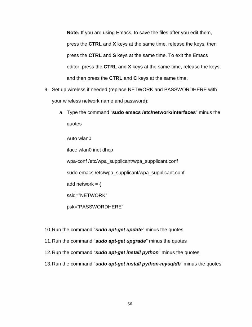
9. Set up wireless if needed (replace NETWORK and PASSWORDHERE with
your wireless network name and password):
a. Type the command “sudo emacs /etc/network/interfaces” minus the
quotes
Auto wlan0
iface wlan0 inet dhcp
wpa-conf /etc/wpa_supplicant/wpa_supplicant.conf
sudo emacs /etc/wpa_supplicant/wpa_supplicant.conf
add network = {
ssid=”NETWORK”
psk=”PASSWORDHERE”
10. Run the command “sudo apt-get update” minus the quotes
11. Run the command “sudo apt-get upgrade” minus the quotes
12. Run the command “sudo apt-get install python” minus the quotes
13. Run the command “sudo apt-get install python-mysqldb” minus the quotes

57
14. Run the command “sudo apt-get install ntpdate” minus the quotes to start
setting up the network time protocol to keep the time and date synchronized
with an external source.
15. Run the command “sudo rm /etc/localtime” minus the quotes.
16. Run the command “ls /usr/share/zoneinfo” minus the quotes.
17. Run the command “ls /usr/share/zoneinfo/America” minus the quotes.
18. Run the command “sudo ln /usr/share/zoneinfo/America/Los_Angeles
/etc/localtime” minus the quotes.
19. Run the command “sudo service ntp restart” minus the quotes.
20. Run the command “date” minus the quotes to verify the date and time are
correct.
21. Run the command “sudo raspi-config”. Use the down/up arrows on the
keyboard to choose “expand_rootfs” and press the “return” key. A
confirmation will be shown after completion to tell the user the filesystem will
be resized after reboot. This step ensures the Raspbian software is able to
utilize the full size of the memory card being used.
22. Run the command “sudo reboot” to restart the Pi, then wait about 30
seconds. You will need to reconnect to the Pi after restart is complete.
23. After remotely connecting back to Pi, run the command “sudo shutdown
now” to shut down the Pi. Unplug the Pi after 20 – 30 seconds after running
this command.

58
Garden/Watering Pi
Overview This Raspberry Pi is supposed to read 3 sensor values (temperature, humidity, soil
moisture). Those sensor values are reported every hour to the central server
database. The soil moisture is checked every 6 hours and a pump to water the
plant/garden is turned on for 2 minutes if the soil is dry. These timing values can be
customized.
Parts Needed/Used 1.) Raspberry Pi 2 Model B
2.) 16GB Lexar 300x micro SD memory card
3.) Suptronics X300 expansion board
4.) SunFounder 2 channel 5v Relay Shield Module
5.) Power supply for Raspberry Pi (2 – 2.5 Amp)
6.) Water pump or water valve solenoid for tap water use (12v pump was used
here)
7.) Jumper Wires
8.) DHT22 AM2032 Digital Temperature Humidity Sensor
9.) 10k Ohm Resistor (brown black orange gold bands on resistor) for DHT22
Sensor
10.) Small size bread board
Instructions 1. Follow base Pi setup steps

59
Wire the Pi
2. Wire the Pi with the X300 expansion board, sensors, pump, and relay as
shown below. You will be using the GPIO pins located here (red rectangle) on
the top of the Raspberry Pi and X300 expansion board:

60
Download Sensor Libraries
3. Log into the Pi either using the Putty program or in the “Terminal” window in
the Raspbian operating system.

61
4. In either the Putty program or in the “Terminal” window in the Raspbian
operating system, run the command “git clone
https://github.com/adafruit/Adafruit_Python_DHT.git” to download the
library for the DHT22 sensor.
5. Run the command “cd Adafruit_Python_DHT”
6. Run the command “sudo python setup.py install” to start the install.
Set up Pi Module in Central Server Interface
7. Open a web browser on your computer and navigate to the central server
web interface (http://192.168.1.247). Log in to the site and click on the
“Modules”. Then click on the “Add Module” link.
8. Enter the information for the module you are setting up and click on the
“Submit” button.

62
You should now see the module you created in the list of modules for this
site. Take note of the module ID number as you will need it later on (In this
project, this module was module ID number 1.
9. Click on the “Sensors” tab at the top navigation bar of the web interface.
Then click on the “Add New Sensor” link to enter the sensor on the module
you just created, and then click on the “Submit” button.
In this instance, we will need to create the sensors Temperature (C), Humidity
(%), and Soil Moisture for Module ID 1. The final list of sensors should look
something like this:

63
You will need to know the sensor ID numbers in case they are different than
what is in the python source code files. It should be noted that the Chart File
Name field can be entered by clicking on the “Edit” icon for each of the
sensors and entering the file names as shown above. This field is used to tell
the interface where to find the pages to display the charts for the sensor data
later on.
Copy Source Program Files and Modify as Necessary
10. Using a program such as WinSCP or Filezilla, copy the .py files from the
project repository “Central Server\Garden Pi” file folder to the VM using
SCP/SSH. The destination path should be can be anywhere you decide (I
used the user home folder on the Pi).
11. Edit the Python .py files as shown in the next few steps, either before you
copy the files to the Pi or after copying. (I edited them using emacs on the Pi
using the command “emacs report-status.py” and “emacs check-and-
water.py”). You will need to make sure the host, user, passwd, and db fields
are filled in correctly.
db =
MySQLdb.connect(host="192.168.1.247",user="myautomationsql",
passwd="aut0Mat1on8",db="HomeAutomation")
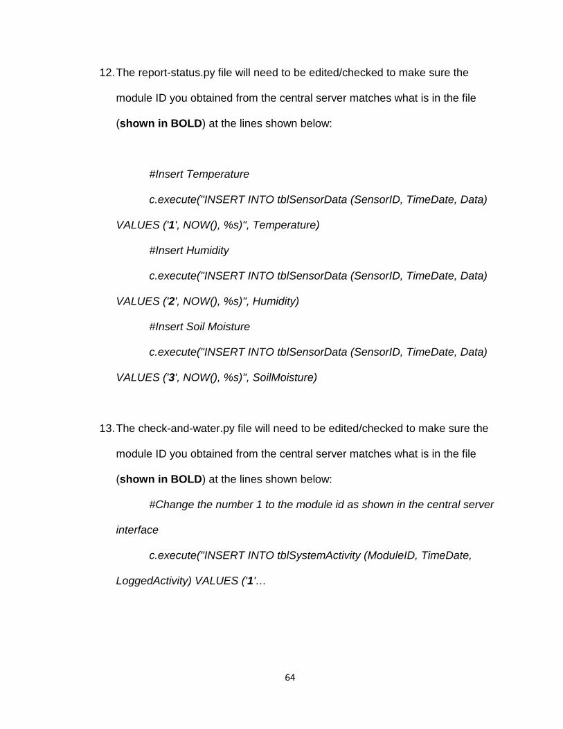
64
12. The report-status.py file will need to be edited/checked to make sure the
module ID you obtained from the central server matches what is in the file
(shown in BOLD) at the lines shown below:
#Insert Temperature
c.execute("INSERT INTO tblSensorData (SensorID, TimeDate, Data)
VALUES ('1', NOW(), %s)", Temperature)
#Insert Humidity
c.execute("INSERT INTO tblSensorData (SensorID, TimeDate, Data)
VALUES ('2', NOW(), %s)", Humidity)
#Insert Soil Moisture
c.execute("INSERT INTO tblSensorData (SensorID, TimeDate, Data)
VALUES ('3', NOW(), %s)", SoilMoisture)
13. The check-and-water.py file will need to be edited/checked to make sure the
module ID you obtained from the central server matches what is in the file
(shown in BOLD) at the lines shown below:
#Change the number 1 to the module id as shown in the central server
interface
c.execute("INSERT INTO tblSystemActivity (ModuleID, TimeDate,
LoggedActivity) VALUES ('1'…
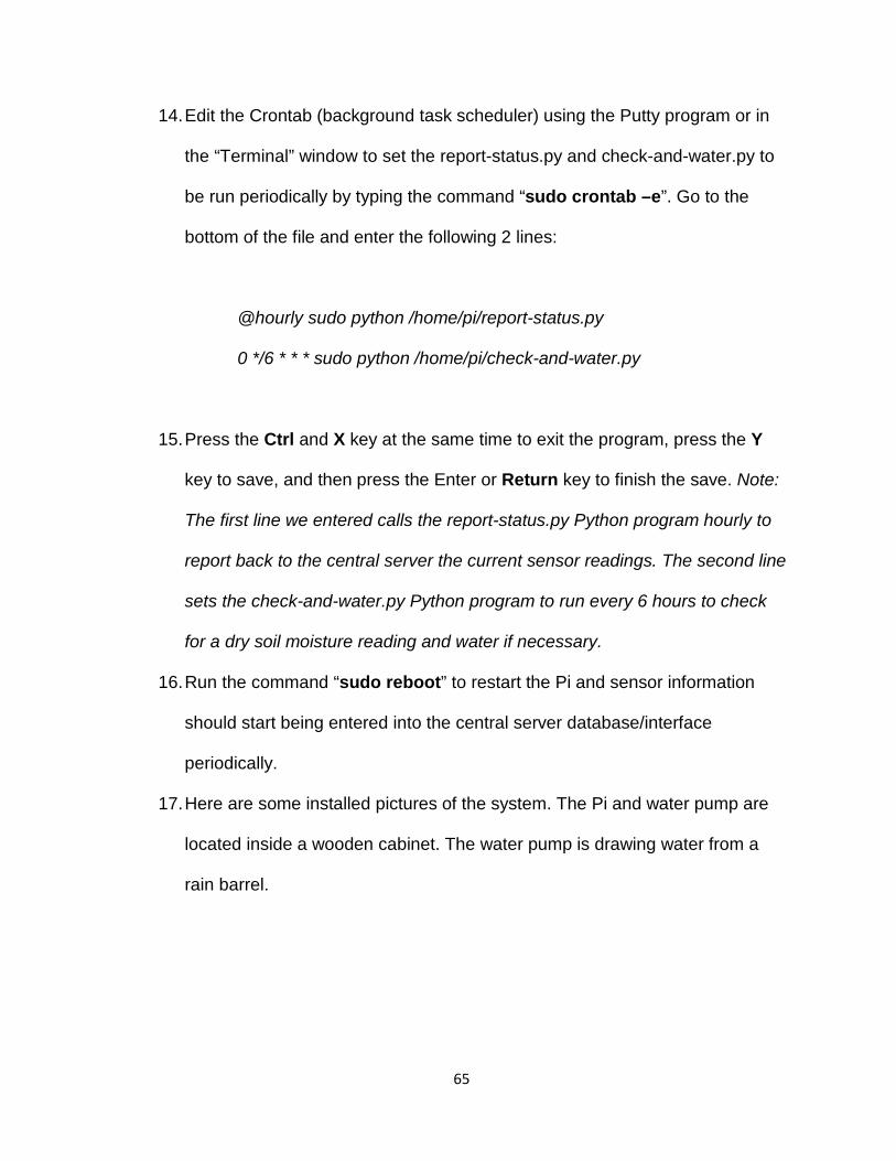
65
14. Edit the Crontab (background task scheduler) using the Putty program or in
the “Terminal” window to set the report-status.py and check-and-water.py to
be run periodically by typing the command “sudo crontab –e”. Go to the
bottom of the file and enter the following 2 lines:
@hourly sudo python /home/pi/report-status.py
0 */6 * * * sudo python /home/pi/check-and-water.py
15. Press the Ctrl and X key at the same time to exit the program, press the Y
key to save, and then press the Enter or Return key to finish the save. Note:
The first line we entered calls the report-status.py Python program hourly to
report back to the central server the current sensor readings. The second line
sets the check-and-water.py Python program to run every 6 hours to check
for a dry soil moisture reading and water if necessary.
16. Run the command “sudo reboot” to restart the Pi and sensor information
should start being entered into the central server database/interface
periodically.
17. Here are some installed pictures of the system. The Pi and water pump are
located inside a wooden cabinet. The water pump is drawing water from a
rain barrel.

66
The soil moisture sensor is slightly buried in the soil beside the plant/garden
to be watered.
67
NFC Garage Door Opener
Overview This Raspberry Pi is supposed to read NFC cards/tags, check with a central server
for authentication, and then power cycle a relay to open a garage door open if a
valid card/tag is used. Also, two LEDs are used to display whether a valid user’s
NFC tag is used or not.
Parts Needed/Used 1.) Raspberry Pi 2 Model B
2.) 16GB Lexar 300x micro SD memory card
3.) Suptronics X300 expansion board
4.) PN532 NFC/RFID Controller Breakout Board – v1.6
5.) SunFounder 2 channel 5v Relay Shield Module
6.) Power supply for Raspberry Pi (2 – 2.5 Amp)
7.) Red LED
8.) Blue or Green LED
9.) 2 x 330 Ohm Resistors (4 bands on Resistors should be orange, orange,
brown, and gold)
10.) Jumper Wires
11.) NFC Tag (This project used the Mifare NFC card that came with the
NFC board as well as a Mifare Classic (13.56Mhz RFID/NFC clear keychain
fob)
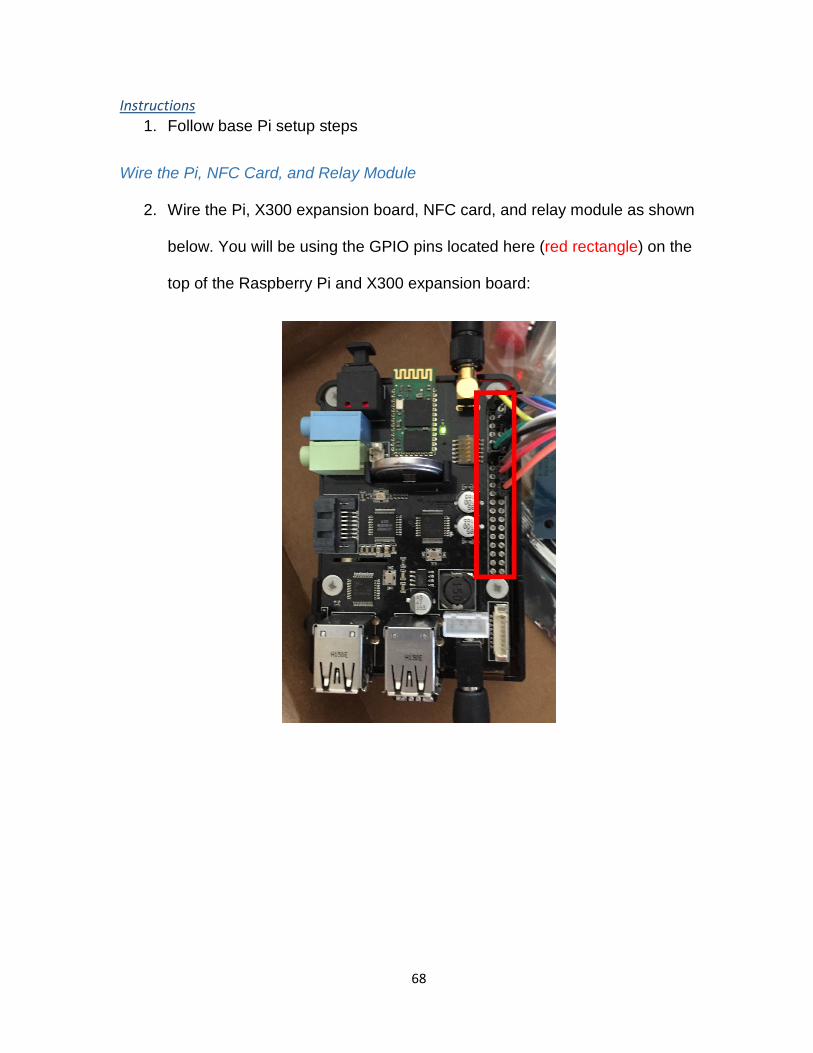
68
Instructions 1. Follow base Pi setup steps
Wire the Pi, NFC Card, and Relay Module
2. Wire the Pi, X300 expansion board, NFC card, and relay module as shown
below. You will be using the GPIO pins located here (red rectangle) on the
top of the Raspberry Pi and X300 expansion board:

69
Set up Pi to use SPI and NFC Card
3. Either use the Putty program to remotely connect to the Pi or open the
“Terminal” program in the GUI of the Raspberry Pi.

70
4. Enable SPI by running the command “sudo raspi-config”, press the up/down
arrow keys on the keyboard to choose “9 Advanced Options”.
5. Select “Yes” to enable SPI (Serial Peripheral Interface) for the NFC card to
work. You will most likely also have to choose “Yes” to automatically load the
kernel module. Use the right arrow key to select the “Finish” button and
choose “Yes” to reboot the Pi. You will have to remotely connect to the Pi or
use the GUI again after the reboot.
6. Run the command “sudo apt-get install build-essential python-dev git”.
7. Run the command “cd ~”.
8. Run the command “git clone
https://github.com/adafruit/Adafruit_Python_PN532.git”.
9. Run the command “cd Adafruit_Python_PN532”.
10. Run the command “sudo python setup.py install”.

71
Set up Pi Module in Central Server Interface
11. Open a web browser on your computer and navigate to the central server
web interface (http://192.168.1.247). Log in to the site and click on the
“Modules”. Then click on the “Add Module” link.
12. Enter the information for the module you are setting up and click on the
“Submit” button.
You should now see the module you created in the list of modules for this
site. Take note of the module ID number as you will need it later on (In this
project, this module was module ID number 5.
13. Click on the “Sensors” tab at the top navigation bar of the web interface.
Then click on the “Add New Sensor” link to enter the sensor on the module
you just created, and then click on the “Submit” button.
The final list of sensors should look something like this:

72
You will need to know the sensor ID number in case it is different than what is
in the python source code file.
14. Use an NFC tag and get its ID by using your terminal window and typing “cd
Adafruit_Python_PN532/examples”. Then run the command “sudo python
readmifare.py”. When you put the NFC tag over the NFC card, you should
see something like this:
Note: The UID value is the text you need to take down immediately following
the “0x”.
15. Navigate to the central server web interface (http://192.168.1.247) and go to
the “Users” tab. Click on the edit icon that looks like a pencil for the user you
are assigning this NFC tag/card to. In the “NFC Card ID” field, enter the UID
value from the last step without the “0x”.

73
16. Repeat as necessary.
Copy Source Program Files and Modify as Necessary
17. Using a program such as WinSCP or Filezilla, copy the nfc-read.py file from
the project repository “Central Server\NFC Pi” file folder to the VM using
SCP/SSH. The destination path should be can be anywhere you decide (I
used the user home folder on the Pi).
18. Edit the Python .py files, either before you copy the files to the Pi or after
copying. (I edited them using emacs on the Pi using the command “emacs
nfc-read.py”). You will need to make sure the host, user, passwd, and db
fields are filled in correctly.
db =
MySQLdb.connect(host="192.168.1.247",user="myautomationsql",
passwd="aut0Mat1on8",db="HomeAutomation")

74
19. The nfc-read.py file will need to be edited/checked to make sure the module
ID you obtained from the central server matches what is in the file (shown in
BOLD) at the lines as shown below:
c.execute("INSERT INTO tblSystemActivity (ModuleID, TimeDate,
LoggedActivity) VALUES ('5'…
Note: There are multiple instances of the line shown above. All instances
have to be checked to ensure the module ID number is correct.
20. Set up the Pi to automatically start the NFC reader Python program when the
Pi turns on. We will do this by first creating a launcher script by typing “emacs
launcher.sh” in a terminal window. Then enter the following:
#!/bin/sh
# launcher.sh
# Navigate to home directory, then execute python script
cd /
cd home/pi
sudo python nfc-read.py
21. Save the file by pressing the Ctrl and S keys, then the Ctrl and X keys to
close the emacs editor.

75
22. Type the command “chmod 755 launcher.sh” and press the Return key to
make the file executable. Also, create a log file folder by running the
command “mkdir logs”.
23. Edit the Crontab (background task schedule) to run the launcher.sh file on
start up by running the command “sudo crontab -e”. Go to the bottom of the
file and enter the following line:
@reboot sh /home/pi/launcher.sh >/home/pi/logs/cronlog 2>&1
Press the Ctrl and X key at the same time to exit the program, press the Y
key to save, and then press the Enter or Return key to finish the save.
24. Restarting the Pi by running the command “sudo reboot” should now start
the nfc-read.py Python program on startup. Data from sensor reads should
also be uploaded to the central server database/interface.

76
APPENDIX B – Source Code nfc-read.py
# Example of detecting and reading a block from a MiFare NFC card. # Author: Tony DiCola and Guang Yew # Copyright (c) 2015 Adafruit Industries # # Permission is hereby granted, free of charge, to any person obtaining a copy # of this software and associated documentation files (the "Software"), to deal # in the Software without restriction, including without limitation the rights # to use, copy, modify, merge, publish, distribute, sublicense, and/or sell # copies of the Software, and to permit persons to whom the Software is # furnished to do so, subject to the following conditions: # # The above copyright notice and this permission notice shall be included in all # copies or substantial portions of the Software. # # THE SOFTWARE IS PROVIDED "AS IS", WITHOUT WARRANTY OF ANY KIND, EXPRESS OR # IMPLIED, INCLUDING BUT NOT LIMITED TO THE WARRANTIES OF MERCHANTABILITY, # FITNESS FOR A PARTICULAR PURPOSE AND NONINFRINGEMENT. IN NO EVENT SHALL THE # AUTHORS OR COPYRIGHT HOLDERS BE LIABLE FOR ANY CLAIM, DAMAGES OR OTHER # LIABILITY, WHETHER IN AN ACTION OF CONTRACT, TORT OR OTHERWISE, ARISING FROM, # OUT OF OR IN CONNECTION WITH THE SOFTWARE OR THE USE OR OTHER DEALINGS IN THE # SOFTWARE. import binascii import sys import RPi.GPIO as GPIO import Adafruit_PN532 as PN532 import time import MySQLdb # Configuration for a Raspberry Pi: CS = 18 MOSI = 23 MISO = 24

77
SCLK = 25 GARAGERLYBCM = 27 GOODLEDINDICATOR = 26 BADLEDINDICATOR = 20 INVALIDERRORCOUNT = 0 GPIO.setmode(GPIO.BCM) # Create an instance of the PN532 class. pn532 = PN532.PN532(cs=CS, sclk=SCLK, mosi=MOSI, miso=MISO) # Call begin to initialize communication with the PN532. Must be done before # any other calls to the PN532! pn532.begin() # Get the firmware version from the chip and print(it out.) ic, ver, rev, support = pn532.get_firmware_version() ###print('Found PN532 with firmware version: {0}.{1}'.format(ver, rev)) # Configure PN532 to communicate with MiFare cards. pn532.SAM_configuration() # Read NFC sensor loop to check for valid NFC tag and actuate garage door opener if valid along with logging activity to central server database # Main loop to detect cards and read a block. # print('Waiting for MiFare card...') while True: # Check if a card is available to read. uid = pn532.read_passive_target() # Try again if no card is available. if uid is None: continue # Set uid variable with NFC tag read uid = binascii.hexlify(uid) print(uid) try: # Database Connection db = MySQLdb.connect(host="192.168.1.247",user="myautomationsql",passwd="aut0Mat1on8",db="HomeAutomation") except: print("DB Connection error") try:

78
c = db.cursor() # Insert log activity entry into central automation server database c.execute("INSERT INTO tblSensorData (SensorID, TimeDate, Data) VALUES ('4', NOW(), %s)", uid) c.execute("INSERT INTO tblSystemActivity (ModuleID, TimeDate, LoggedActivity) VALUES ('5', NOW(), 'Garage door NFC reader has read card ID ' %s)", uid) # Check to see if NFC tag read is a valid user c.execute("SELECT id FROM tblUsers WHERE NFCCardID = %s", uid) data = c.fetchall() print("Selected ID from DB") # print the number of valid users found for NFC tag read count = c.rowcount print(count) if (count == 1): #light blue LED, trigger garage door opener and write to central server log print "Garage relay trigger and LED indicator on..." GPIO.setmode(GPIO.BCM) GPIO.setup(GOODLEDINDICATOR, GPIO.OUT) GPIO.output(GOODLEDINDICATOR, True) GPIO.setup(GARAGERLYBCM, GPIO.OUT) GPIO.output(GARAGERLYBCM, False) time.sleep(1) GPIO.output(GARAGERLYBCM, True) print "Garage relay finished and LED indicator off..." GPIO.output(GOODLEDINDICATOR, False) c.execute("INSERT INTO tblSystemActivity (ModuleID, TimeDate, LoggedActivity) VALUES ('5', NOW(), 'Garage door has been actuated by Card ID ' %s)", uid) else: # If there are more than 3 consecutive invalid NFC tags read, turn on red LED and don't read any more tags for 5 mins INVALIDERRORCOUNT += 1 print(INVALIDERRORCOUNT) if (INVALIDERRORCOUNT > 2): print('System disabled for 15 mins') c.execute("INSERT INTO tblSystemActivity (ModuleID, TimeDate, LoggedActivity) VALUES ('5', NOW(), 'Garage Door NFC Reader is disabled for 15 mins after 3 consecutive invalid attempts')") GPIO.setmode(GPIO.BCM) GPIO.setup(BADLEDINDICATOR, GPIO.OUT)

79
GPIO.output(BADLEDINDICATOR, True) time.sleep(10) # Reset error count to 0 INVALIDERRORCOUNT = 0 # Turn off red LED GPIO.output(BADLEDINDICATOR, False) else: # Light red LED due to invalid card and write to central server log GPIO.setmode(GPIO.BCM) GPIO.setup(BADLEDINDICATOR, GPIO.OUT) GPIO.output(BADLEDINDICATOR, True) time.sleep(3) GPIO.output(BADLEDINDICATOR, False) c.execute("INSERT INTO tblSystemActivity (ModuleID, TimeDate, LoggedActivity) VALUES ('5', NOW(), 'Invalid NFC card has been read with the ID ' %s)", uid) print('No valid user found.') c.close() time.sleep(3) db.commit() db.close() # print ("DBEnd") except: # db.rollback() print "Database Error..." time.sleep(2)

80
check-and-water.py
#!/usr/bin/python # Copyright (c) 2014 Adafruit Industries # Author: Tony DiCola and Guang Yew # Permission is hereby granted, free of charge, to any person obtaining a copy # of this software and associated documentation files (the "Software"), to deal # in the Software without restriction, including without limitation the rights # to use, copy, modify, merge, publish, distribute, sublicense, and/or sell # copies of the Software, and to permit persons to whom the Software is # furnished to do so, subject to the following conditions: # The above copyright notice and this permission notice shall be included in all # copies or substantial portions of the Software. # THE SOFTWARE IS PROVIDED "AS IS", WITHOUT WARRANTY OF ANY KIND, EXPRESS OR # IMPLIED, INCLUDING BUT NOT LIMITED TO THE WARRANTIES OF MERCHANTABILITY, # FITNESS FOR A PARTICULAR PURPOSE AND NONINFRINGEMENT. IN NO EVENT SHALL THE # AUTHORS OR COPYRIGHT HOLDERS BE LIABLE FOR ANY CLAIM, DAMAGES OR OTHER # LIABILITY, WHETHER IN AN ACTION OF CONTRACT, TORT OR OTHERWISE, ARISING FROM, # OUT OF OR IN CONNECTION WITH THE SOFTWARE OR THE USE OR OTHER DEALINGS IN THE # SOFTWARE. import Adafruit_DHT import MySQLdb import RPi.GPIO as GPIO import time # Sensor should be set to Adafruit_DHT.DHT11, # Adafruit_DHT.DHT22, or Adafruit_DHT.AM2302. sensor = Adafruit_DHT.DHT22 # Example using a Raspberry Pi with DHT sensor # connected to GPIO23. pin = 4

81
Rly1BGPIO = 23 Rly2BGPIO = 24 # Try to grab a sensor reading. Use the read_retry method which will retry up # to 15 times to get a sensor reading (waiting 2 seconds between each retry). Humidity, Temperature = Adafruit_DHT.read_retry(sensor, pin) if Humidity is not None and Temperature is not None: print 'Temp={0:0.1f}*C Humidity={1:0.1f}%'.format(Temperature, Humidity) #Format Temperature for later use FormattedTemp = round(Temperature, 2) else: print 'Failed to get reading. Try again!' #Check Soil Moisture GPIO.setmode(GPIO.BCM) GPIO.setup(17, GPIO.IN) GPIO.setup(Rly1BGPIO, GPIO.OUT) GPIO.setup(Rly2BGPIO, GPIO.OUT) print "" print "soil moisture below:" print GPIO.input(17) soilMoisture = GPIO.input(17) GPIO.cleanup() GPIO.setmode(GPIO.BCM) GPIO.setup(Rly1BGPIO, GPIO.OUT) GPIO.setup(Rly2BGPIO, GPIO.OUT) if soilMoisture: #Soil is dry so start watering on relay 1 print "Soil is dry" #GPIO.setmode(GPIO.BCM) GPIO.output(Rly1BGPIO, False) #Connect to database try: db = MySQLdb.connect(host="192.168.1.247",user="myautomationsql",passwd="aut0Mat1on8",db="HomeAutomation") except: print "Unable to connect to the database."

82
c = db.cursor() c.execute("INSERT INTO tblSystemActivity (ModuleID, TimeDate, LoggedActivity) VALUES ('1', NOW(), 'Watering activated for 2 minutes when garden temperature was %s degrees Celcius')", FormattedTemp) db.commit() else: #GPIO.setmode(GPIO.BCM) GPIO.output(Rly1BGPIO, True) print "soil is moist already" #NOT USED-Turn off relays #GPIO.setmode(GPIO.BCM) #GPIO.setup(Rly1BGPIO, GPIO.OUT) #GPIO.setup(Rly2BGPIO, GPIO.OUT) #Start watering GPIO.output(Rly1BGPIO, False) #Not used yet until we wire another pump for additional watering capacity #GPIO.output(Rly2BGPIO, True) #Water for 2 minutes and stop relay/motor time.sleep(120) GPIO.output(Rly1BGPIO, True) db.close()
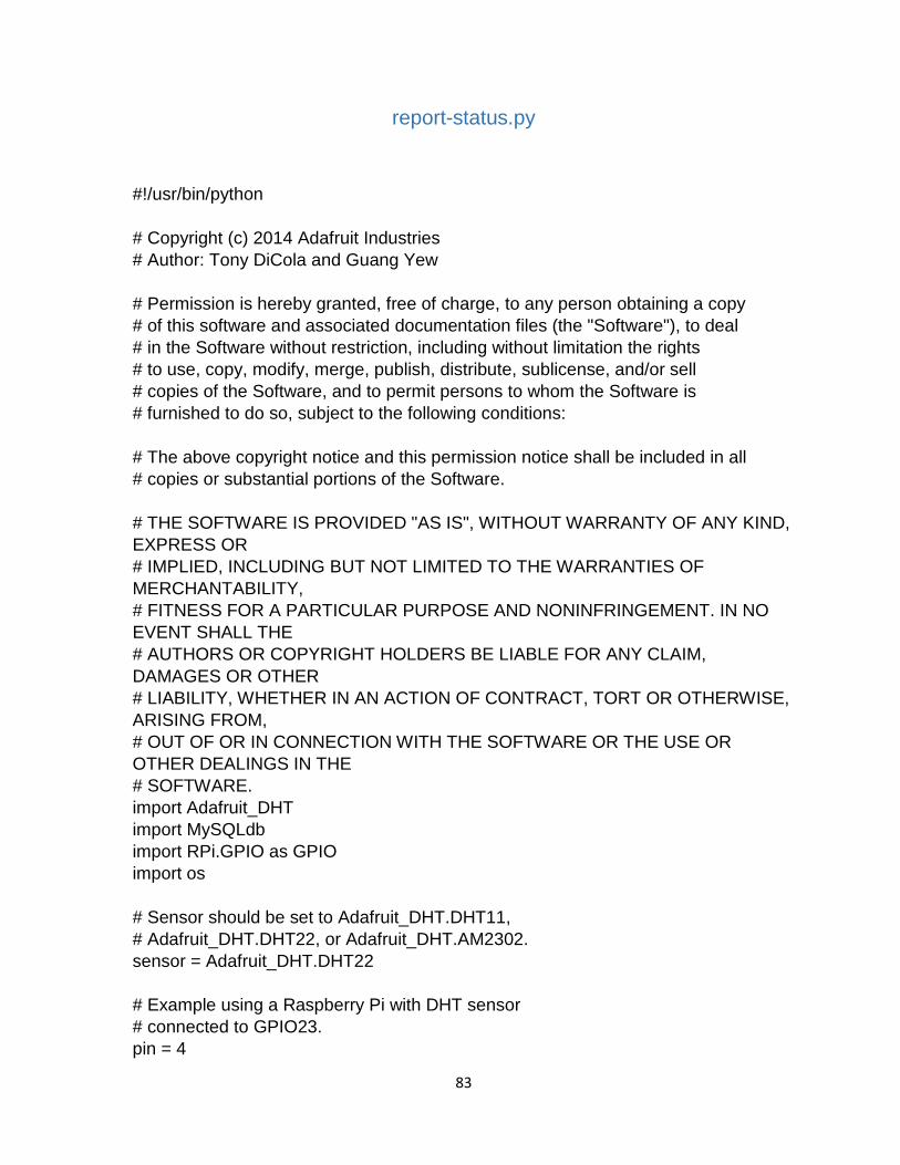
83
report-status.py
#!/usr/bin/python # Copyright (c) 2014 Adafruit Industries # Author: Tony DiCola and Guang Yew # Permission is hereby granted, free of charge, to any person obtaining a copy # of this software and associated documentation files (the "Software"), to deal # in the Software without restriction, including without limitation the rights # to use, copy, modify, merge, publish, distribute, sublicense, and/or sell # copies of the Software, and to permit persons to whom the Software is # furnished to do so, subject to the following conditions: # The above copyright notice and this permission notice shall be included in all # copies or substantial portions of the Software. # THE SOFTWARE IS PROVIDED "AS IS", WITHOUT WARRANTY OF ANY KIND, EXPRESS OR # IMPLIED, INCLUDING BUT NOT LIMITED TO THE WARRANTIES OF MERCHANTABILITY, # FITNESS FOR A PARTICULAR PURPOSE AND NONINFRINGEMENT. IN NO EVENT SHALL THE # AUTHORS OR COPYRIGHT HOLDERS BE LIABLE FOR ANY CLAIM, DAMAGES OR OTHER # LIABILITY, WHETHER IN AN ACTION OF CONTRACT, TORT OR OTHERWISE, ARISING FROM, # OUT OF OR IN CONNECTION WITH THE SOFTWARE OR THE USE OR OTHER DEALINGS IN THE # SOFTWARE. import Adafruit_DHT import MySQLdb import RPi.GPIO as GPIO import os # Sensor should be set to Adafruit_DHT.DHT11, # Adafruit_DHT.DHT22, or Adafruit_DHT.AM2302. sensor = Adafruit_DHT.DHT22 # Example using a Raspberry Pi with DHT sensor # connected to GPIO23. pin = 4

84
Rly1BGPIO = 23 Rly2BGPIO = 24 # Try to grab a sensor reading. Use the read_retry method which will retry up # to 15 times to get a sensor reading (waiting 2 seconds between each retry). Humidity, Temperature = Adafruit_DHT.read_retry(sensor, pin) if Humidity is not None and Temperature is not None: print 'Temp={0:0.1f}*C Humidity={1:0.1f}%'.format(Temperature, Humidity) else: print 'Failed to get reading. Try again!' #Initiate Database Connection try: db = MySQLdb.connect(host="192.168.1.247",user="myautomationsql", passwd="aut0Mat1on8",db="HomeAutomation") except: print "Unable to connect to the database." #Get sensor readings and insert into database try: #GPIO.setWarnings(False) GPIO.setmode(GPIO.BCM) GPIO.setup(17, GPIO.IN) SoilMoisture = GPIO.input(17) c = db.cursor() #Insert Temperature c.execute("INSERT INTO tblSensorData (SensorID, TimeDate, Data) VALUES ('1', NOW(), %s)", Temperature) #Insert Humidity c.execute("INSERT INTO tblSensorData (SensorID, TimeDate, Data) VALUES ('2', NOW(), %s)", Humidity) #Insert Soil Moisture c.execute("INSERT INTO tblSensorData (SensorID, TimeDate, Data) VALUES ('3', NOW(), %s)", SoilMoisture) c.execute("""SELECT * from tblSensorData""") db.commit() except: db.rollback() print "Database Error..."

85
#dbdata = c.fetchall() #print "DB Data: " #print dbdata #GPIO.setmode(GPIO.BCM) #GPIO.setup(17, GPIO.IN) #print "" #print "soil moisture below:" #print GPIO.input(17) GPIO.cleanup() #Turn off relays GPIO.setmode(GPIO.BCM) GPIO.setup(Rly1BGPIO, GPIO.OUT) GPIO.setup(Rly2BGPIO, GPIO.OUT) GPIO.output(Rly1BGPIO, True) GPIO.output(Rly2BGPIO, True) #Start watering #os.system('start-watering.py') db.close()

86
homeautomation.sql -- phpMyAdmin SQL Dump -- version 4.0.10deb1 -- http://www.phpmyadmin.net -- -- Host: localhost -- Generation Time: Sep 04, 2016 at 12:08 PM -- Server version: 5.5.49-0ubuntu0.14.04.1 -- PHP Version: 5.5.9-1ubuntu4.16 SET SQL_MODE = "NO_AUTO_VALUE_ON_ZERO"; SET time_zone = "+00:00"; /*!40101 SET @OLD_CHARACTER_SET_CLIENT=@@CHARACTER_SET_CLIENT */; /*!40101 SET @OLD_CHARACTER_SET_RESULTS=@@CHARACTER_SET_RESULTS */; /*!40101 SET @OLD_COLLATION_CONNECTION=@@COLLATION_CONNECTION */; /*!40101 SET NAMES utf8 */; -- -- Database: `HomeAutomation` -- CREATE DATABASE IF NOT EXISTS `HomeAutomation` DEFAULT CHARACTER SET latin1 COLLATE latin1_swedish_ci; USE `HomeAutomation`; -- -------------------------------------------------------- -- -- Table structure for table `new_record` -- DROP TABLE IF EXISTS `new_record`; CREATE TABLE IF NOT EXISTS `new_record` ( `id` int(11) NOT NULL AUTO_INCREMENT, `trn_date` datetime NOT NULL, `name` varchar(50) NOT NULL, `age` int(11) NOT NULL, `submittedby` varchar(50) NOT NULL, PRIMARY KEY (`id`) ) ENGINE=InnoDB DEFAULT CHARSET=latin1 AUTO_INCREMENT=1 ; -- --------------------------------------------------------

87
-- -- Table structure for table `tblModules` -- DROP TABLE IF EXISTS `tblModules`; CREATE TABLE IF NOT EXISTS `tblModules` ( `ID` int(11) NOT NULL AUTO_INCREMENT, `Name` varchar(255) NOT NULL, `Location` varchar(255) NOT NULL, `IP` varchar(255) NOT NULL, PRIMARY KEY (`ID`) ) ENGINE=InnoDB DEFAULT CHARSET=latin1 AUTO_INCREMENT=6 ; -- -------------------------------------------------------- -- -- Table structure for table `tblSensorData` -- DROP TABLE IF EXISTS `tblSensorData`; CREATE TABLE IF NOT EXISTS `tblSensorData` ( `ID` int(11) NOT NULL AUTO_INCREMENT, `SensorID` int(11) NOT NULL, `TimeDate` datetime NOT NULL, `Data` varchar(255) NOT NULL, PRIMARY KEY (`ID`) ) ENGINE=InnoDB DEFAULT CHARSET=latin1 AUTO_INCREMENT=5815 ; -- -------------------------------------------------------- -- -- Table structure for table `tblSensors` -- DROP TABLE IF EXISTS `tblSensors`; CREATE TABLE IF NOT EXISTS `tblSensors` ( `ID` int(11) NOT NULL AUTO_INCREMENT, `Name` varchar(255) NOT NULL, `ModuleID` int(11) NOT NULL, `chartFilename` varchar(255) NOT NULL, PRIMARY KEY (`ID`) ) ENGINE=InnoDB DEFAULT CHARSET=latin1 AUTO_INCREMENT=5 ; -- --------------------------------------------------------

88
-- -- Table structure for table `tblSystemActivity` -- DROP TABLE IF EXISTS `tblSystemActivity`; CREATE TABLE IF NOT EXISTS `tblSystemActivity` ( `ActivityID` int(11) NOT NULL AUTO_INCREMENT, `ModuleID` int(11) NOT NULL, `LoggedActivity` varchar(255) NOT NULL, `TimeDate` datetime NOT NULL, PRIMARY KEY (`ActivityID`) ) ENGINE=InnoDB DEFAULT CHARSET=latin1 AUTO_INCREMENT=379 ; -- -------------------------------------------------------- -- -- Table structure for table `tblUsers` -- DROP TABLE IF EXISTS `tblUsers`; CREATE TABLE IF NOT EXISTS `tblUsers` ( `id` int(4) NOT NULL AUTO_INCREMENT, `username` varchar(65) NOT NULL DEFAULT '', `password` varchar(65) NOT NULL DEFAULT '', `accesslevel` varchar(65) NOT NULL, `NFCCardID` varchar(50) NOT NULL, PRIMARY KEY (`id`) ) ENGINE=InnoDB DEFAULT CHARSET=latin1 AUTO_INCREMENT=5 ; -- -- Dumping data for table `tblUsers` -- INSERT INTO `tblUsers` (`id`, `username`, `password`, `accesslevel`, `NFCCardID`) VALUES (1, 'admin', 'e4a93e6d2ec6da13df4c42d500543352', 'admin', '31060f0b'), /*!40101 SET CHARACTER_SET_CLIENT=@OLD_CHARACTER_SET_CLIENT */; /*!40101 SET CHARACTER_SET_RESULTS=@OLD_CHARACTER_SET_RESULTS */; /*!40101 SET COLLATION_CONNECTION=@OLD_COLLATION_CONNECTION */;