Highly efficient TiO 2 nanotube photocatalyst for simultaneous hydrogen production and copper...
8
Highly efficient TiO 2 nanotube photocatalyst for simultaneous hydrogen production and copper removal from water Shiping Xu, Jiawei Ng, Alan Jianhong Du, Jincheng Liu, Darren Delai Sun* School of Civil and Environmental Engineering, Nanyang Technological University, 50 Nanyang Avenue, Singapore 639798, Singapore article info Article history: Received 15 December 2010 Received in revised form 7 March 2011 Accepted 8 March 2011 Available online 6 April 2011 Keywords: TiO 2 nanotube Hydrogen production Copper removal abstract 1-D mesoporous TiO 2 nanotube (TNT) with large BET surface area was successfully synthesized by a hydrothermal-calcination process, and employed for simultaneous pho- tocatalytic H 2 production and Cu 2þ removal from water. Cu 2þ , across a wide concentration range of 8e800 ppm, was removed rapidly from water under irradiation. The removed Cu 2þ then combined with TNT to produce efficient Cu incorporated TNT (Cu-TNT) photocatalyst for H 2 production. Average H 2 generation rate recorded across a 4 h reaction was between 15.7 and 40.2 mmol h 1 g 1 catalyst , depending on initial Cu 2þ /Ti ratio in solution, which was optimized at 10 atom%. In addition, reduction process of Cu 2þ was also a critical factor in governing H 2 evolution. In comparison with P25, its large surface area and 1-D tubular structure endowed TNT with higher photocatalytic activity in both Cu 2þ removal and H 2 production. Copyright ª 2011, Hydrogen Energy Publications, LLC. Published by Elsevier Ltd. All rights reserved. 1. Introduction Massive global utilization of fossil fuels as energy source has exacerbated worldwide concern on global warming and depletion of natural resources. H 2 has been regarded as an excellent alternative, owing to its high energy content, zero emission of green house gases, and ease of storage and distribution. Currently, majority of H 2 demands are met by steam reforming of natural gases, however this process does not mitigate dependence on fossil fuels, and even produces green house gases. Ever since Fujishima and Honda reported photoelectrochemical water splitting at a TiO 2 electrode, direct photo-splitting of water has been recognized as a promising method for renewable H 2 production [1]. However, H 2 generation efficiency over bare TiO 2 is low, mainly due to the fast recombination of electron/hole pairs [2]. Recently, Cu incorporated TiO 2 (CueTiO 2 ) was reported to be cost-effective and possess excellent H 2 generation activity under sacrificial conditions [3e9]. Several Cu species (Cu/ Cu 2 O/CuO) have been reported to be active [10e13], and various facile methods, like in-situ photo-deposition, are able to produce efficient CueTiO 2 [14], underlining the potential of CueTiO 2 in photocatalytic H 2 production. Cu is widely used in electrical industries, transportation, industrial machinery and military supplies, leading to fast depletion of limited Cu reserves and severe contamination of industrial wastewaters [15]. Thus, waste metal recovery from water can contribute towards resource conservation and mitigation of metal pollution. Common methods employed for Cu recovery today include chemical or electrolytic precipitation, activated carbon adsorption, ion exchange and membrane separation, but they are either too costly or inef- ficient for low concentration levels [16]. Recently, photo- catalytic reduction of Cu 2þ over TiO 2 has been investigated [17e19], and shows lower cost with higher efficiency. More- over, this method is also applicable in fabrication of Cu deposited TiO 2 photocatalyst, which could potentially be an active photocatalyst for H 2 production. However to date, * Corresponding author. Tel.: þ65 67906273; fax: þ65 67910676. E-mail address: [email protected] (D.D. Sun). Available at www.sciencedirect.com journal homepage: www.elsevier.com/locate/he international journal of hydrogen energy 36 (2011) 6538 e6545 0360-3199/$ e see front matter Copyright ª 2011, Hydrogen Energy Publications, LLC. Published by Elsevier Ltd. All rights reserved. doi:10.1016/j.ijhydene.2011.03.047
-
Upload
independent -
Category
Documents
-
view
1 -
download
0
Transcript of Highly efficient TiO 2 nanotube photocatalyst for simultaneous hydrogen production and copper...

i n t e rn a t i o n a l j o u r n a l o f h y d r o g e n en e r g y 3 6 ( 2 0 1 1 ) 6 5 3 8e6 5 4 5
Avai lab le at www.sc iencedi rect .com
journa l homepage : www.e lsev ie r . com/ loca te /he
Highly efficient TiO2 nanotube photocatalyst for simultaneoushydrogen production and copper removal from water
Shiping Xu, Jiawei Ng, Alan Jianhong Du, Jincheng Liu, Darren Delai Sun*
School of Civil and Environmental Engineering, Nanyang Technological University, 50 Nanyang Avenue, Singapore 639798, Singapore
a r t i c l e i n f o
Article history:
Received 15 December 2010
Received in revised form
7 March 2011
Accepted 8 March 2011
Available online 6 April 2011
Keywords:
TiO2 nanotube
Hydrogen production
Copper removal
* Corresponding author. Tel.: þ65 67906273; fE-mail address: [email protected] (D.D.
0360-3199/$ e see front matter Copyright ªdoi:10.1016/j.ijhydene.2011.03.047
a b s t r a c t
1-D mesoporous TiO2 nanotube (TNT) with large BET surface area was successfully
synthesized by a hydrothermal-calcination process, and employed for simultaneous pho-
tocatalytic H2 production and Cu2þ removal from water. Cu2þ, across a wide concentration
range of 8e800 ppm, was removed rapidly from water under irradiation. The removed Cu2þ
then combined with TNT to produce efficient Cu incorporated TNT (Cu-TNT) photocatalyst
for H2 production. Average H2 generation rate recorded across a 4 h reaction was between
15.7 and 40.2 mmol h�1 g�1catalyst, depending on initial Cu2þ/Ti ratio in solution, which was
optimized at 10 atom%. In addition, reduction process of Cu2þ was also a critical factor in
governing H2 evolution. In comparison with P25, its large surface area and 1-D tubular
structure endowed TNT with higher photocatalytic activity in both Cu2þ removal and H2
production.
Copyright ª 2011, Hydrogen Energy Publications, LLC. Published by Elsevier Ltd. All rights
reserved.
1. Introduction Cu2O/CuO) have been reported to be active [10e13], and
Massive global utilization of fossil fuels as energy source has
exacerbated worldwide concern on global warming and
depletion of natural resources. H2 has been regarded as an
excellent alternative, owing to its high energy content, zero
emission of green house gases, and ease of storage and
distribution. Currently, majority of H2 demands are met by
steam reforming of natural gases, however this process does
not mitigate dependence on fossil fuels, and even produces
green house gases. Ever since Fujishima and Honda reported
photoelectrochemical water splitting at a TiO2 electrode,
direct photo-splitting of water has been recognized as
a promising method for renewable H2 production [1].
However, H2 generation efficiency over bare TiO2 is low,
mainly due to the fast recombination of electron/hole pairs [2].
Recently, Cu incorporated TiO2 (CueTiO2) was reported to be
cost-effective and possess excellent H2 generation activity
under sacrificial conditions [3e9]. Several Cu species (Cu/
ax: þ65 67910676.Sun).2011, Hydrogen Energy P
various facile methods, like in-situ photo-deposition, are able
to produce efficient CueTiO2 [14], underlining the potential of
CueTiO2 in photocatalytic H2 production.
Cu is widely used in electrical industries, transportation,
industrial machinery and military supplies, leading to fast
depletion of limited Cu reserves and severe contamination of
industrial wastewaters [15]. Thus, waste metal recovery from
water can contribute towards resource conservation and
mitigation of metal pollution. Common methods employed
for Cu recovery today include chemical or electrolytic
precipitation, activated carbon adsorption, ion exchange and
membrane separation, but they are either too costly or inef-
ficient for low concentration levels [16]. Recently, photo-
catalytic reduction of Cu2þ over TiO2 has been investigated
[17e19], and shows lower cost with higher efficiency. More-
over, this method is also applicable in fabrication of Cu
deposited TiO2 photocatalyst, which could potentially be an
active photocatalyst for H2 production. However to date,
ublications, LLC. Published by Elsevier Ltd. All rights reserved.

i n t e r n a t i o n a l j o u r n a l o f h y d r o g e n en e r g y 3 6 ( 2 0 1 1 ) 6 5 3 8e6 5 4 5 6539
major reports about Cu2þ reduction over TiO2 have merely
focused on Cu2þ removal, and no study about simultaneous H2
production with Cu2þ removal has been reported.
1-D TiO2 nanotube has attracted considerable attention
since its discovery by Kasuga et al. [20] using a simple hydro-
thermal treatment of TiO2 powder in NaOH aqueous solution.
Many efforts have been devoted into understanding the
formation mechanism [21], optimizing fabrication conditions
[22], and studying the properties of TNT [23]. It is known that
TNT possesses large specific surface area, mesoporous struc-
ture, and efficient electron conductivity [24]. TNT has exhibi-
ted immense potential in a wide variety of applications,
ranging from environmental purification [25,26], photo-
catalysis [27], energy storage [28], and gas sensing [29],
however little is known about its performance in photo-
catalytic H2 production. Furthermore, no report about utiliza-
tion of TNT in simultaneous metal ions removal and H2
production could be found in open literature. Hereinwe report
for the first time, an effective Cu2þ removal and H2 production
being simultaneously achieved over highly efficient TNT. This
may offer a potential andmeritorious solution for treatment of
metal containing wastewater with concurrent H2 production.
In this study, TNT was successfully fabricated by a hydro-
thermal reaction followed by calcination process, and then
employed in photocatalytic reaction to evaluate its perfor-
mance in simultaneous Cu2þ removal and H2 generation. The
experimental results revealed that Cu2þ can be recovered
readily from water by TNT to produce a highly active Cu-TNT
photocatalyst for H2 production, and H2 evolution was largely
governed by Cu2þ reduction process. In addition, initial Cu2þ/Ti ratio was proved to be critical in H2 production, and its
effect was also discussed in this paper.
2. Experimental
2.1. Synthesis and characterization of TNT
TNT was fabricated via a typical hydrothermal method fol-
lowed by calcination process. Degussa P25 (Germany) powder
was added to 10 M NaOH (Merck, AR) aqueous solution, fol-
lowed by an ultrasonic process and thorough mixing. The
homogeneous suspensionwas then hydrothermally treated in
a Teflon-lined autoclave at 150 �C for 48 h. The obtained
precipitate was first washed with de-ionized water (Milli-Q,
ultrapure), and then dispersed under continuous stirring into
0.1 M HCl (Merck, AR) for 24 h. The acid treatment was
repeated for 3 times, and the product was washed thoroughly
with de-ionizedwater until the resulting pHwas neutral. After
drying in a freeze dryer, the product was calcined at 400 �C for
2 h to obtain the final TNT photocatalyst.
X-ray diffraction (XRD) pattern of the fabricated TNT was
obtained using a Bruker D8 Advance X-ray diffractometer with
monochromated high-intensity Cu Ka radiation (l ¼ 1.5418 A).
Element composition of the photocatalyst was analyzed using
an energy dispersive X-ray spectrometer (EDS) attached to
a scanning electron microscope (Jeol JSM-6360). Sample
morphology was studied using a field-emission scanning
electron microscope (FESEM, Jeol JSM-6340F), and a high-
resolution transmission electron microscope (HRTEM, Jeol
JEM-2010) at 200 kV. BET surface area andpore size distribution
were determined using a Micromeritics ASAP 2010 system.
Diffuse-reflectance spectra were recorded by a Thermo
Scientific Evolution 300 UVevisible spectrophotometer,
equipped with an integration sphere. X-ray photoelectron
spectroscopy (XPS) analysis was carried out in an ultrahigh
vacuum chamber with a base pressure below 2.66 � 10�7 Pa at
room temperature. Photoemission spectra were recorded by
a Kratos Axis Ultra spectrometer equipped with standard
monochromatic Al Ka excitation source (hn ¼ 1486.71 eV). All
binding energies were referenced to C 1s at 284.8 eV.
2.2. Photocatalytic reaction
The photocatalytic reaction was performed in an inner-irra-
diation type Pyrex reactor (volume: 270 ml) equipped with
a 400 W high pressure Hg lamp (Riko, UVL-400HA) as the light
source. To maintain a constant reactor temperature of 25 �C,a quartz water jacket, which was cooled by recycled water,
was utilized to cover the lamp. Cu(NO3)2 (Merck, GR) was first
dissolved in 10 volume% methanol (Fisher, HPLC) water
mixture with Cu2þ concentrations of 8, 80, 400 and 800 ppm,
and TNT was then dispersed into the above solution at
a dosage of 1 g L�1. Cu/Ti atom ratio was controlled at 1%, 10%,
50% and 100%, and the corresponding results were respec-
tively denoted as TNT-1%, TNT-10%, TNT-50% and TNT-100%.
A magnetic stirrer was placed at the bottom of the reactor to
homogenize the suspension throughout the reaction. Prior to
irradiation, the photocatalyst suspension was de-aerated
thoroughly for 30 min by nitrogen gas purging.
To investigate the competition of Cu2þ reduction and effect
of re-oxidation of reduced Cu species on H2 generation,
control experiments were carried out as follows: after normal
TNT-10% reaction for 2 h, the fabricated Cu-TNTwas collected
and washed thoroughly with de-ionized water, and then
dispersed in fresh methanol solution with (or without) pres-
ence of Cu2þ (Cu2þ/Ti ¼ 10 atom%) prior to the photocatalytic
reactions.
To evaluate the activity of TNT, P25, with an initial Cu2þ/Tiratio of 10%, was chosen as a benchmark, and denoted as P25-
10%. Control experiment for H2 generation over bare TNT was
also conducted without addition of Cu precursor.
Cu2þ concentration in solution was quantified at stated
time intervals by an inductively coupled plasma emission
spectroscopy (ICP, Perkin Elmer Optima 2000DV). Gas
produced via the photocatalytic reaction was analyzed using
an off-line TCD-type gas chromatography (Agilent 7890A, HP-
PLOT MoleSieve/5A). pH value of the solution was determined
by a Horiba F-53 pH meter.
3. Results and discussion
3.1. Characterization of TNT
XRD pattern and EDS spectrum of the fabricated TNT are
shown in Fig. 1. XRD pattern of as-prepared TNT exhibited
characteristic features of anatase TiO2 (JCPDS 21-1272). No
vague peaks associated with other crystal structures were
observed. In the EDS spectrum, peaks of C, O, Au and Ti were

Fig. 1 e XRD pattern and EDS spectrum (inset) of TNT.
Fig. 2 e (a) FESEM and (b) HRTEM images of TNT.
Fig. 3 e Isotherm of N2 adsorption/desorption on the
surface of TNT. Inset: pore size distribution (BJH
desorption) of TNT.
i n t e rn a t i o n a l j o u r n a l o f h y d r o g e n en e r g y 3 6 ( 2 0 1 1 ) 6 5 3 8e6 5 4 56540
prominent, where C and Au could be respectively attributed to
the carbon tape used and sample coating; henceforth, the
as-prepared sample contained only O and Ti elements. XRD
and EDS results confirmed the final fabricated product to be
pure anatase TiO2.
Microstructure of the fabricated TNTwas studied by FESEM
and HRTEM (Fig. 2). It revealed that the as-prepared photo-
catalyst possessed a multilayered nanotubular structure.
Lengths of the nanotubes ranged from c.a.100 nm to 400 nm.
Inner and outer diameters of the nanotubes were c.a. 5e7 nm
and 9e12 nm, respectively, and each tube characterized
a constant diameter along its length. In accordance to XRD
and EDS results, we confirmed that the alkaline hydrothermal
treatment and calcination process had completely trans-
formed the P25 precursor to pure anatase TiO2 nanotubes.
N2 adsorption/desorption isotherm of the as-prepared TNT
is depicted in Fig. 3. It can be seen that the isotherm exhibited
a typical type IV curve with a hysteresis loop, indicating mes-
oporous structure of the photocatalyst [30]. In addition, the
relatively broad hysteresis loop of the isotherm suggested
a wide distribution of pore sizes. In the pore size distribution
curve of TNT, two distinct peaks of c.a. 2e3 nm and 20e30 nm
wereclearlyobserved.Considering themorphologyofTNT, the
smaller peak could be attributed to pores inside thenanotubes;
whereas the larger pores referred to pores between the tubes
[22]. Mesoporous nanotubular structure endowed the fabri-
cated TNTwith a large BET surface area of 279m2 g-1, which is
beneficial towards enhancing photoactivity.
UVevisible absorption spectrum of TNT (shown in Fig. 4)
was similar to that of P25, with a strong absorption band at
around 350 nm, associated with excitation of electron in the
O 2p orbital to the Ti 3d level. As compared to P25, the
absorption onset of TNT shifted slightly towards the shorter
wavelength range, giving rise to a small increase in band gap
to 3.25 eV (P25: 3.15 eV), calculated based on the Kubel-
kaeMunk function [31]. A wide band gap is beneficial for high
photocatalytic activity, since it augments redox potential of
the photo-induced electrons and holes.
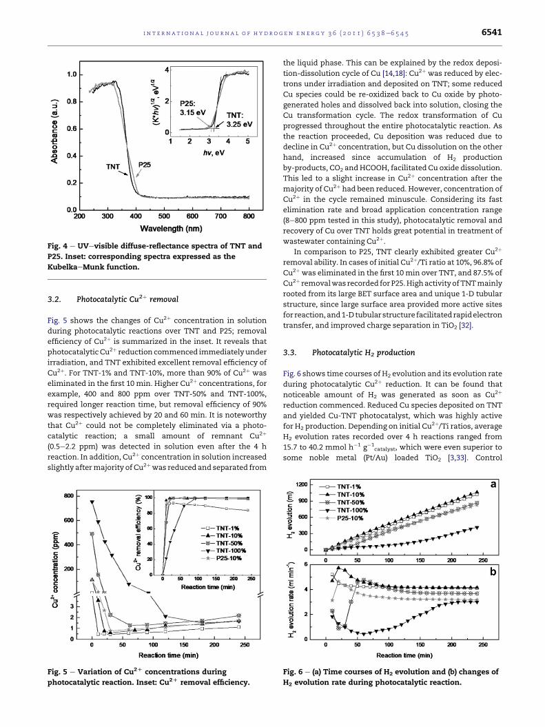
Fig. 4 e UVevisible diffuse-reflectance spectra of TNT and
P25. Inset: corresponding spectra expressed as the
KubelkaeMunk function.
i n t e r n a t i o n a l j o u r n a l o f h y d r o g e n en e r g y 3 6 ( 2 0 1 1 ) 6 5 3 8e6 5 4 5 6541
3.2. Photocatalytic Cu2þ removal
Fig. 5 shows the changes of Cu2þ concentration in solution
during photocatalytic reactions over TNT and P25; removal
efficiency of Cu2þ is summarized in the inset. It reveals that
photocatalyticCu2þ reduction commenced immediately under
irradiation, and TNT exhibited excellent removal efficiency of
Cu2þ. For TNT-1% and TNT-10%, more than 90% of Cu2þ was
eliminated in the first 10 min. Higher Cu2þ concentrations, for
example, 400 and 800 ppm over TNT-50% and TNT-100%,
required longer reaction time, but removal efficiency of 90%
was respectively achieved by 20 and 60 min. It is noteworthy
that Cu2þ could not be completely eliminated via a photo-
catalytic reaction; a small amount of remnant Cu2þ
(0.5e2.2 ppm) was detected in solution even after the 4 h
reaction. In addition, Cu2þ concentration in solution increased
slightly aftermajority of Cu2þwas reduced and separated from
Fig. 5 e Variation of Cu2D concentrations during
photocatalytic reaction. Inset: Cu2D removal efficiency.
the liquid phase. This can be explained by the redox deposi-
tion-dissolution cycle of Cu [14,18]: Cu2þ was reduced by elec-
trons under irradiation and deposited on TNT; some reduced
Cu species could be re-oxidized back to Cu oxide by photo-
generated holes and dissolved back into solution, closing the
Cu transformation cycle. The redox transformation of Cu
progressed throughout the entire photocatalytic reaction. As
the reaction proceeded, Cu deposition was reduced due to
decline in Cu2þ concentration, but Cu dissolution on the other
hand, increased since accumulation of H2 production
by-products, CO2 andHCOOH, facilitated Cu oxide dissolution.
This led to a slight increase in Cu2þ concentration after the
majority of Cu2þ had been reduced. However, concentration of
Cu2þ in the cycle remained minuscule. Considering its fast
elimination rate and broad application concentration range
(8e800 ppm tested in this study), photocatalytic removal and
recovery of Cu over TNT holds great potential in treatment of
wastewater containing Cu2þ.In comparison to P25, TNT clearly exhibited greater Cu2þ
removal ability. In cases of initial Cu2þ/Ti ratio at 10%, 96.8% of
Cu2þ was eliminated in the first 10min over TNT, and 87.5% of
Cu2þ removalwas recorded for P25.HighactivityofTNTmainly
rooted from its large BET surface area and unique 1-D tubular
structure, since large surface area provided more active sites
for reaction,and1-Dtubular structure facilitated rapidelectron
transfer, and improved charge separation in TiO2 [32].
3.3. Photocatalytic H2 production
Fig. 6 shows time courses of H2 evolution and its evolution rate
during photocatalytic Cu2þ reduction. It can be found that
noticeable amount of H2 was generated as soon as Cu2þ
reduction commenced. Reduced Cu species deposited on TNT
and yielded Cu-TNT photocatalyst, which was highly active
for H2 production. Depending on initial Cu2þ/Ti ratios, averageH2 evolution rates recorded over 4 h reactions ranged from
15.7 to 40.2 mmol h�1 g�1catalyst, which were even superior to
some noble metal (Pt/Au) loaded TiO2 [3,33]. Control
Fig. 6 e (a) Time courses of H2 evolution and (b) changes of
H2 evolution rate during photocatalytic reaction.

Fig. 7 e Changes of (a) H2 evolution rate and (b) Cu2D
concentration when Cu-TNT (TNT-10%) is applied to fresh
reaction solution with (or without) presence of Cu2D (Cu2D/
Ti [ 10 atom%).
i n t e rn a t i o n a l j o u r n a l o f h y d r o g e n en e r g y 3 6 ( 2 0 1 1 ) 6 5 3 8e6 5 4 56542
experiment performed over pure TNT without Cu2þ in solu-
tion, exhibited negligible H2 evolution (data not shown). The
high H2 productivity of Cu-TNT can be attributed to efficient
charge separation in TNT, where excess electrons were
accumulated on Cu species, which in turn provided reduction
sites for H2 formation [4].
From the time courses of H2 evolution (Fig. 6a), it is readily
observed that initial Cu2þ/Ti ratio had an important influence
on H2 generation activity. TNT-10% exhibited the greatest
activity, followed by TNT-1%, TNT-50%, and TNT-100%, which
was consistent with our previous study [12]. Higher Cu2þ/Tiratio increased Cu content in the fabricated Cu-TNT, which
provided more active sites for H2 formation, but at the same
time, deposited Cu species on TNT surface increased UV light
blockage to the photocatalyst. Henceforth, based on experi-
mental results, a Cu2þ/Ti atom ratio of 10% provided the
optimized balance between the effects of active sites and UV
light interception, which resulted in the highest activity.
Changes in H2 evolution rates (Fig. 6b) revealed that H2
generation was heavily controlled by reduction of Cu2þ, andthe control mode was dependent on initial Cu2þ/Ti ratio.
Higher Cu2þ/Ti ratios compelled larger changes to H2 evolu-
tion rates due to greater Cu2þ reduction. For TNT-50% and
TNT-100% with Cu2þ/Ti ratio greater than the optimized 10%,
changes to H2 generation rate can be divided into three
distinctive stages: H2 generation rate initially decreased with
time and later ascended to a maximum, before finally
declining slightly to a stable state. These changes were closely
related to Cu transformation during the photocatalytic reac-
tion. Take TNT-50% as example, 98.9% of the Cu2þ was
reduced and deposited on TNT in the first 20 min, therefore
capturing most of the photo-generated electrons from TNT
and gradually blocking UV light access to TNT, which led to its
low and decreasing H2 generation rate during this period.
Subsequently, with deceleration of Cu2þ reduction, protons
began to successfully compete with Cu2þ for electrons and
reduced to H2, therefore increasing H2 generation rate. In
addition, the redox deposition-dissolution transformation of
Cu over TNT enhanced dispersion of Cu species within the
photocatalyst [14], thus promoting H2 generation further. The
third stage started when maximum Cu2þ reduction was ach-
ieved (60 min for TNT-50%). During this period, Cu dissolution
was more dominant over the deposition phenomenon in the
redox transformation; hencemore Cu on TNT dissolved in the
solution, disrupting the optimum Cu condition achieved from
the second stage and suppressing H2 generation activity to
a certain extent. Thereafter, H2 generation rate became steady
owing to dynamic functioning of Cu redox transformation.
The described three-stage reaction was also manifested in
TNT-100%. However, contrary to TNT-50% and TNT-100%, the
first stage was not characteristic in the case of TNT-10%
(optimal Cu2þ/Ti ratio). H2 generation rate initially increased
with Cu2þ reduction, since the increase in H2 formation active
sites was predominant over UV light scattering effect under
this condition. However, when Cu dissolution exceeded
deposition (20 min for TNT-10%), H2 generation rate began to
decline before stabilizing at a relatively high value. This was
similar to the third stage of TNT-50% and TNT-100%. In the
case of TNT-1%, since initial Cu2þ concentration was consid-
erably low, maximum Cu2þ reduction was achieved in less
than 10 min under irradiation; therefore, H2 evolution rate
declinedwith time and stabilized later, exhibiting only the last
stage in higher Cu2þ/Ti ratio cases.
Control experiments were conducted by applying Cu-TNT
(TNT-10%) to fresh reaction solution with (or without) pres-
ence of Cu2þ to delineate the effect of Cu2þ reduction on H2
generation.The results are summarized in Fig. 7.Withaddition
of Cu2þ, H2 evolution rate declined immediately since Cu2þ
reduction took precedence due to its more positive redox
potential (EØCu2þ
/Cu¼ 0.34 V), and thus imposing a competition
effect on proton reduction; the impact was more pronounced
when more Cu2þ was added (data not shown). This supported
the initial lowH2 generation rate in the three-stage reaction.As
the reaction progressed, protons could successfully compete
with Cu2þ for electrons when majority of the Cu2þ was
reduced, hence H2 evolution ratewas noted to recover quickly.
This observation mirrored the ascendant period in TNT-50%
and TNT-100%. On the other hand, the absence of Cu2þ in the
fresh reaction solution would evoke a slight decline of H2
evolution rate, as observed in the last phase of the three-stage
reaction. This related with re-oxidation and dissolution of
deposited Cu species, and has been detailedly investigated in
our previous study [14].
In comparison with Cu-P25, in-situ synthesis of Cu-TNT
was much faster, and Cu-TNT exhibited greater H2 generation
activity. Average H2 generation rate over Cu-TNT in the 4 h
reaction was 28.9% higher than that of Cu-P25 (40.2 vs.
31.2 mmol h�1 g�1catalyst), under same Cu2þ/Ti ¼ 10 atom%
conditions. Superiority of TNT was credited to its large BET
surface area and unique 1-D tubular structure, which was
discussed earlier in photocatalytic Cu2þ removal.
In addition, it was observed that without agitation, more
than 90% of Cu-TNT would settle down at the bottom of the
reactor within 5min, resulting in a supernatant of high clarity.
The high settling ability of Cu-TNT facilitates its recovery from
the liquid phase.

Fig. 8 e EDS spectra of Cu-TNT (a: TNT-1%; b: TNT-10%; c: TNT-50%; d: TNT-100%).
Fig. 9 e XRD patterns of Cu-TNT (a: TNT-1%; b: TNT-10%; c:
TNT-50%; d: TNT-100%).
i n t e r n a t i o n a l j o u r n a l o f h y d r o g e n en e r g y 3 6 ( 2 0 1 1 ) 6 5 3 8e6 5 4 5 6543
3.4. Characterization of photocatalyst after reaction
EDS analysis was carried out after the photocatalytic reaction
to investigate Cu distribution. From the EDS results (Fig. 8), Cu/
Ti atom ratios in the final photocatalysts were similar but
slightly higher than initial Cu2þ/Ti ratios in solution before
irradiation. It indicated that the leached Cu2þ from solution
was transferred to the solid phase and combinedwith TNT; Cu
species were prone to accumulate on surface of TNT rather
than interstitially dissolved into the crystal lattice. Deposition
of Cu on TNT surface, especially at higher Cu content, would
cause interception of UV light access to TNT, which supported
the hypothesis of initial decrease of H2 generation rate in the
three-stage reaction. In addition, elemental mapping images
(data not shown) revealed that, all elements were well
distributed throughout the bulk of the final photocatalysts.
Chemical state of Cu in solid phase after photocatalytic
reduction has been intensively investigated, but controversial
results were reported. Complete reduction of Cu2þ to metallic
Cu was observed in some studies [19,34]; while some
researchers concluded that the reduced Cu species was
a mixture of metallic Cu and Cu2O [35,36]. Foster et al. [15]
reported that Cu2þ could only be reduced to Cuþ, and
complete reduction to metallic Cu was not observed. To verify
the chemical state of Cu, XRD and XPS analyses of Cu-TNT
were carried out in this study.
XRD spectra from Fig. 9 present the changes in chemical
state of Cu over TNT after photocatalytic reduction. XRD
patternscorresponding toCuspeciesvariedaccording to initial
Cu2þ/Ti ratios. ForTNT-1%andTNT-10%,noobviousCuphases
weredetected. SinceEDS results confirmed theexistenceofCu,
it is believed that thedimensionsof Cu species in both samples
were belowXRDdetection limit, evidencinghighCudispersion
in the samples [37]. In contrast, diffractionpeaks of CuO (JCPDS
48-1548) and metallic Cu (JCPDS 4-836) were respectively
identified inTNT-50%andTNT-100%.Differentchemical states
of Cuwere also observed in XPS analysis (Fig. 10). In this study,
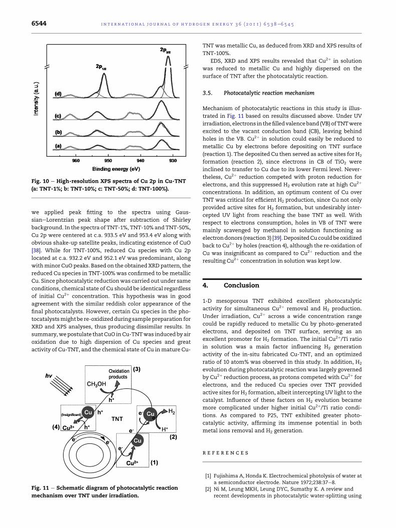
Fig. 10 e High-resolution XPS spectra of Cu 2p in Cu-TNT
(a: TNT-1%; b: TNT-10%; c: TNT-50%; d: TNT-100%).
i n t e rn a t i o n a l j o u r n a l o f h y d r o g e n en e r g y 3 6 ( 2 0 1 1 ) 6 5 3 8e6 5 4 56544
we applied peak fitting to the spectra using Gaus-
sianeLorentzian peak shape after subtraction of Shirley
background. In the spectra of TNT-1%, TNT-10%andTNT-50%,
Cu 2p were centered at c.a. 933.5 eV and 953.4 eV along with
obvious shake-up satellite peaks, indicating existence of CuO
[38]. While for TNT-100%, reduced Cu species with Cu 2p
located at c.a. 932.2 eV and 952.1 eV was predominant, along
withminor CuO peaks. Based on the obtainedXRDpattern, the
reduced Cu species in TNT-100%was confirmed to be metallic
Cu. Since photocatalytic reductionwas carried out under same
conditions, chemical state of Cu should be identical regardless
of initial Cu2þ concentration. This hypothesis was in good
agreement with the similar reddish color appearance of the
final photocatalysts. However, certain Cu species in the pho-
tocatalystsmight be re-oxidizedduring samplepreparation for
XRD and XPS analyses, thus producing dissimilar results. In
summary,wepostulate thatCuO inCu-TNTwas inducedbyair
oxidation due to high dispersion of Cu species and great
activity of Cu-TNT, and the chemical state of Cu inmature Cu-
Fig. 11 e Schematic diagram of photocatalytic reaction
mechanism over TNT under irradiation.
TNT wasmetallic Cu, as deduced from XRD and XPS results of
TNT-100%.
EDS, XRD and XPS results revealed that Cu2þ in solution
was reduced to metallic Cu and highly dispersed on the
surface of TNT after the photocatalytic reaction.
3.5. Photocatalytic reaction mechanism
Mechanism of photocatalytic reactions in this study is illus-
trated in Fig. 11 based on results discussed above. Under UV
irradiation, electrons in thefilledvalenceband (VB) ofTNTwere
excited to the vacant conduction band (CB), leaving behind
holes in the VB. Cu2þ in solution could easily be reduced to
metallic Cu by electrons before depositing on TNT surface
(reaction 1). The deposited Cu then served as active sites for H2
formation (reaction 2), since electrons in CB of TiO2 were
inclined to transfer to Cu due to its lower Fermi level. Never-
theless, Cu2þ reduction competed with proton reduction for
electrons, and this suppressed H2 evolution rate at high Cu2þ
concentrations. In addition, an optimum content of Cu over
TNT was critical for efficient H2 production, since Cu not only
provided active sites for H2 formation, but undesirably inter-
cepted UV light from reaching the base TNT as well. With
respect to electrons consumption, holes in VB of TNT were
mainly scavenged by methanol in solution functioning as
electrondonors (reaction3) [39].DepositedCucouldbeoxidized
back to Cu2þ by holes (reaction 4), although the re-oxidation of
Cu was insignificant as compared to Cu2þ reduction and the
resulting Cu2þ concentration in solution was kept low.
4. Conclusion
1-D mesoporous TNT exhibited excellent photocatalytic
activity for simultaneous Cu2þ removal and H2 production.
Under irradiation, Cu2þ across a wide concentration range
could be rapidly reduced to metallic Cu by photo-generated
electrons, and deposited on TNT surface, serving as an
excellent promoter for H2 formation. The initial Cu2þ/Ti ratioin solution was a main factor influencing H2 generation
activity of the in-situ fabricated Cu-TNT, and an optimized
ratio of 10 atom% was observed in this study. In addition, H2
evolution during photocatalytic reaction was largely governed
by Cu2þ reduction process, as protons competed with Cu2þ for
electrons, and the reduced Cu species over TNT provided
active sites for H2 formation, albeit intercepting UV light to the
catalyst. Influence of these factors on H2 evolution became
more complicated under higher initial Cu2þ/Ti ratio condi-
tions. As compared to P25, TNT exhibited greater photo-
catalytic activity, affirming its immense potential in both
metal ions removal and H2 generation.
r e f e r e n c e s
[1] Fujishima A, Honda K. Electrochemical photolysis of water ata semiconductor electrode. Nature 1972;238:37e8.
[2] Ni M, Leung MKH, Leung DYC, Sumathy K. A review andrecent developments in photocatalytic water-splitting using

i n t e r n a t i o n a l j o u r n a l o f h y d r o g e n en e r g y 3 6 ( 2 0 1 1 ) 6 5 3 8e6 5 4 5 6545
TiO2 for hydrogen production. Renew Sust Energy Rev 2007;11:401e25.
[3] Sreethawong T, Yoshikawa S. Comparative investigation onphotocatalytic hydrogen evolution over Cu-, Pd-, and Au-loaded mesoporous TiO2 photocatalysts. Catal Commun2005;6:661e8.
[4] Bandara J, Udawatta CPK, Rajapakse CSK. Highly stable CuOincorporated TiO2 catalyst for photocatalytic hydrogenproduction from H2O. Photochem Photobiol Sci 2005;4:857e61.
[5] Choi HJ, Kang M. Hydrogen production from methanol/waterdecomposition in a liquid photosystem using the anatasestructure of Cu loaded TiO2. Int J Hydrogen Energy 2007;32:3841e8.
[6] Jin ZL, Zhang XJ, Li YX, Li SB, Lu GX. 5.1% Apparent quantumefficiency for stable hydrogen generation over eosin-sensitized CuO/TiO2 photocatalyst under visible lightirradiation. Catal Commun 2007;8:1267e73.
[7] Yoong LS, Chong FK, Dutta BK. Development of copper-doped TiO2 photocatalyst for hydrogen production undervisible light. Energy 2009;34:1652e61.
[8] Miwa T, Kaneco S, Katsumata H, Suzuki T, Ohta K, Verma SC,et al. Photocatalytic hydrogen production from aqueousmethanol solution with CuO/Al2O3/TiO2 nanocomposite. Int JHydrogen Energy 2010;35:6554e60.
[9] Gombac V, Sordelli L, Montini T, Delgado JJ, Adamski A,Adami G, et al. CuOxeTiO2 photocatalysts for H2 productionfrom ethanol and glycerol solutions. J Phys Chem A 2010;114:3916e25.
[10] Wu NL, Lee MS. Enhanced TiO2 photocatalysis by Cu inhydrogen production from aqueous methanol solution. Int JHydrogen Energy 2004;29:1601e5.
[11] Sakata Y, Yamamoto T, Okazaki T, Imamura H, Tsuchiya S.Generation of visible light response on the photocatalyst ofa copper ion containing TiO2. Chem Lett; 1998:1253e4.
[12] Xu SP, Sun DD. Significant improvement of photocatalytichydrogen generation rate over TiO2 with deposited CuO. Int JHydrogen Energy 2009;34:6096e104.
[13] Wu YQ, Lu GX, Li SB. The role of Cu(I) species forphotocatalytic hydrogen generation over CuOx/TiO2. CatalLett 2009;133:97e105.
[14] Xu SP, Ng JW, Zhang XW, Bai HW, Sun DD. Fabrication andcomparison of highly efficient Cu incorporated TiO2
photocatalyst for hydrogen generation from water. Int JHydrogen Energy 2010;35:5254e61.
[15] Foster NS, Noble RD, Koval CA. Reversible photoreductivedeposition and oxidative dissolution of copper ions intitanium dioxide aqueous suspensions. Environ Sci Technol1993;27:350e6.
[16] Troupis A, Hiskia A, Papaconstantinou E. Photocatalyticreduction and recovery of copper by polyoxometalates.Environ Sci Technol 2002;36:5355e62.
[17] Yamazaki S, Iwai S, Yano J, Taniguchi H. Kinetic studies ofreductive deposition of copper(II) ions photoassisted bytitanium dioxide. J Phys Chem A 2001;105:11285e90.
[18] Barakat MA, Chen YT, Huang CP. Removal of toxic cyanideand Cu(II) Ions from water by illuminated TiO2 catalyst. ApplCatal B 2004;53:13e20.
[19] Canterino M, Di Somma I, Marotta R, Andreozzi R. Kineticinvestigation of Cu(II) ions photoreduction in presence oftitanium dioxide and formic acid. Water Res 2008;42:4498e506.
[20] Kasuga T, Hiramatsu M, Hoson A, Sekino T, Niihara K.Formation of titanium oxide nanotube. Langmuir 1998;14:3160e3.
[21] Chen Q, ZhouWZ, Du GH, Peng LM. Trititanate nanotubesmadeviaasinglealkali treatment.AdvMater2002;14:1208e11.
[22] Bavykin DV, Parmon VN, Lapkin AA, Walsh FC. The effect ofhydrothermal conditions on the mesoporous structure ofTiO2 nanotubes. J Mater Chem 2004;14:3370e7.
[23] Yuan ZY, Su BL. Titanium oxide nanotubes, nanofibers andnanowires. Colloids Surf A 2004;241:173e83.
[24] Bavykin DV, Walsh FC. Elongated titanate nanostructuresand their applications. Eur J Inorg Chem; 2009:977e97.
[25] Zhang X, Pan JH, Fu W, Du AJ, Sun DD. TiO2 nanotubephotocatalytic oxidation for water treatment. Water SciTechnol Water Supply 2009;9:45e9.
[26] Ng J, Zhang X, Zhang T, Pan JH, Du JHA, Sun DD. Constructionof self-organized free-standing TiO2 nanotube arrays foreffective disinfection of drinking water. J Chem TechnolBiotechnol 2010;85:1061e6.
[27] Li CL, Yuan JA, Han BY, Jiang L, Shangguan WF. TiO2
nanotubes incorporated with CdS for photocatalytichydrogen production from splitting water under visible lightirradiation. Int J Hydrogen Energy 2010;35:7073e9.
[28] Armstrong G, Armstrong AR, Canales J, Bruce PG. Nanotubeswith the TiO2-B structure. Chem Commun; 2005:2454e6.
[29] Sennik E, Colak Z, Kilinc N, Ozturk ZZ. Synthesis of highly-ordered TiO2 nanotubes for a hydrogen sensor. Int JHydrogen Energy 2010;35:4420e7.
[30] Gregg SJ, Sing KSW. Adsorption, surface area and porosity.2nd ed. London: Academic Press; 1982.
[31] Michalow KA, Logvinovich D, Weidenkaff A, Amberg M,Fortunato G, Heel A, et al. Synthesis, characterization andelectronic structure of nitrogen-doped TiO2 nanopowder.Catal Today 2009;144:7e12.
[32] Khan MA, Yang OB. Photocatalytic water splitting forhydrogen production under visible light on Ir and Co ionizedtitania nanotube. Catal Today 2009;146:177e82.
[33] Sreethawong T, Puangpetch T, Chavadej S, Yoshikawa S.Quantifying influence of operational parameters onphotocatalytic H2 evolution over Pt-loaded nanocrystallinemesoporous TiO2 prepared by single-step sol-gel processwith surfactant template. J Power Sources 2007;165:861e9.
[34] Reiche H, Dunn WW, Bard AJ. Heterogeneous photocatalyticand photosynthetic deposition of copper on TiO2 and WO3
powders. J Phys Chem 1979;83:2248e51.[35] Jacobs JWM, Kampers FWH, Rikken JMG, Bullelieuwma CWT,
Koningsberger DC. Copper photodeposition on TiO2 studiedwith HREM and EXAFS. J Electrochem Soc 1989;136:2914e23.
[36] Bideau M, Claudel B, Faure L, Rachimoellah M.Photooxidation of formic-acid by oxygen in the presence oftitanium-dioxide and dissolved copper ions-oxygen-transferand reaction-kinetics. Chem Eng Commun 1990;93:167e79.
[37] Xu B, Dong L, Chen Y. Influence of CuO loading on dispersionand reduction behavior of CuO/TiO2 (anatase) system. JChem Soc Faraday Trans 1998;94:1905e9.
[38] Chusuei CC, Brookshier MA, Goodman DW. Correlation ofrelative X-ray photoelectron spectroscopy shake-upintensity with CuO particle size. Langmuir 1999;15:2806e8.
[39] Chen J, Ollis DF, Rulkens WH, Bruning H. Photocatalyzedoxidation of alcohols and organochlorides in the presence ofnative TiO2 and metallized TiO2 suspensions. Part (II):photocatalytic mechanisms. Water Res 1999;33:669e76.


![Low-Cost TiO[sub 2] Photocatalytic Technology for Water Potabilization in Plastic Bottles For Isolated Regions. Photocatalyst Fixation](https://static.fdokumen.com/doc/165x107/633786bbd102fae1b60768d8/low-cost-tiosub-2-photocatalytic-technology-for-water-potabilization-in-plastic.jpg)