High Performance Vector Control Inverter - Amtek.cz
80
24A1-E-0002f High performance enabled by the comprehensive use of Fuji technology. Easy maintenance for the end-user. Maintains safety and protects the environment. Opens up possibilities for the new generation. High Performance Vector Control Inverter
-
Upload
khangminh22 -
Category
Documents
-
view
1 -
download
0
Transcript of High Performance Vector Control Inverter - Amtek.cz

24A1-E-0002f
High performance enabled by the comprehensive use of Fuji technology.
Easy maintenance for the end-user.
Maintains safety and protects the environment.
Opens up possibilities for the new generation.
High Performance Vector Control Inverter

The Dawn of a New EraThe FRENIC-VG is creating a new era via the industry-leading performance.
With the FRENIC-VG, Fuji has concentrated its technologies to deliver the best-performinginverter on the market. In addition to basic performance, this model features the following dramatic improvements: support for previously difficult applications due to technical and capability limitations, easier, more user-friendly maintenance, and environmental friendliness and safety.Fuji Electric proudly introduces the FRENIC-VG to the world.
High performance enabled by the comprehensive use of Fuji technology.
Easy maintenance for the end-user.
Maintains safety and protects the environment.
Opens up possibilities for the new generation.
Unit type
NEWCapacity expansion
realized through adoption of SiC hybrid
module for 690V series inverter stack
CONCEPT
ImprovedControl
Performance
EasierMaintenance
A Wide Rangeof Applications
Adaptation toEnvironmentand Safety
2

Powersupply M
Converter section Inverter section
Converter section Inverter section
Powersupply M
M
Product introduction
Inverter (Unit Type)
This converter is used where no electric power regenerationis required.
Diode rectifier (Stack Type)
RHD-D seriesPMW converter (Unit Type)
RHC-C series*PMW converter (Stack Type)
RHC-D series*(690V:Coming soon)
INV
CNV CNV
Filter stack (Stack Type)
RHF-D series (690V:Coming soon)
CNV Filter
This type consists of the converter and inverter circuits.The inverter can be operated using a commercial power supply.* DC power can also be supplied without using the converter circuit.
- Built-in converter (rectifier)- Built-in control circuit- External DC reactor as standard*- DC input is available.
Structure
Easier arrangement for small-scale system
Features
* Available for 75kW or higher capacity models
Inverter (Stack Type)
The converter and inverter sections are separately set in this type.The converter (diode stack) or PWM converter is required depending on the intended use. Moreover, a combination of inverters can be used with one converter.
INV
Structure
Features
- The converter (rectifier) is separately set.- External control circuit- Built-in DC reactor
- DC supply enables the multi-drive arrangement- Energy can be shared within DC bus lines.- Downsized panel- Large-capacity system is easily built.- Easier maintenance
Converter
This converter is used where electric power regeneration or harmonic control is required. Peripheral devices are separately required.* D series and C series differ in form but show identical function and performance. Please use them according to the installation space and purposes.
Sta
ndar
dS
peci
ficat
ions
Com
mon
Spe
cific
atio
nsTe
rmin
alFu
ncti
ons
Pro
tect
ive
Func
tio
nsE
xter
nal
Dim
ensi
ons
Nam
es an
dFu
nctio
ns o
f Par
tsDe
dica
ted
Mot
orSp
ecifi
catio
nsEx
tern
al Di
mens
ions
of D
edica
ted M
otor
sGu
idelin
es fo
rSu
ppres
sing H
armon
icsW
iring
Dia
gram
Op
tio
ns
3
Series lineup (inverters, converters)
Comprehensive Line-up
Unit
Type Series name FormSpecifications *1(applicable load)
Nominal applied motor [kW]
Stack
Stack
Inverter(FRENIC-VG)
Inverter(FRENIC-VG)
PWM Converter(RHC-D)
Filter stack (RHF-D)
Diode rectifier(RHD-D)
PWM Converter(RHC-C)
HD(LD)
MD
50 100 500 1000 5000
MD(CT)(LD(VT))
MD(LD)
MD(LD)
-
MD(LD)
MD(LD)
MD(LD)
Three-phase 400V series
3.7kW(37kW)3.7kW(37kW) 630kW(710kW)630kW(710kW)1800kW(2000kW)1800kW(2000kW)
7.5kW(11kW)7.5kW(11kW)
30kW(37kW)30kW(37kW)
132kW(160kW)132kW(160kW) 315kW(355kW)315kW(355kW)
315kW(355kW)315kW(355kW)200kW(220kW)200kW
(220kW)
355kW355kW160kW160kW
1450kW(1640kW)1450kW(1640kW)
630kW(710kW)630kW
(710kW)
800kW(1000kW)800kW(1000kW)2400kW(3000kW)2400kW(3000kW)
4800kW(6000kW)4800kW(6000kW)
800kW(1000kW)800kW(1000kW)
1200kW(1200kW)1200kW(1200kW)
1800kW(2000kW)1800kW(2000kW)
315kW(355kW)315kW(355kW)800kW(1000kW)800kW(1000kW)
4800kW(6000kW)4800kW(6000kW)4800kW(6000kW)4800kW(6000kW)4800kW(6000kW)
Isolation-lessIsolation
Isolation-lessIsolation
Direct parallel Multiwinding motor
Direct parallel Multiwinding motor
Direct parallel Multiwinding motor
Isolation-lessIsolation
Parallel connection
630kW(710kW)630kW(710kW)1800kW(2000kW)1800kW(2000kW)
3700kW(4200kW)3700kW(4200kW)
1800kW(2000kW)1800kW(2000kW)
3700kW(4200kW)3700kW(4200kW)
110kW110kW 450kW450kW1200kW1200kWDirect parallel
Multiwinding motor 2600kW2600kW
Type Series name FormSpecifications *1(applicable load)
Nominal applied motor [kW]
Inverter(FRENIC-VG)
PWM Converter(RHC-D)
(Coming soon)Filter stack
(RHF-D)(Coming soon)
Diode rectifier(RHD-D)
50 100 500 1000 5000
MD(LD)
-
MD(LD)
MD(LD)
Three-phase 690V series
90kW(110kW)
90kW(110kW)
132kW(160kW)132kW(160kW)
450kW(450kW)450kW(450kW)
450kW450kW220kW(250kW)220kW(250kW)
450kW450kW160kW160kW
2000kW2000kW
1200kW(1200kW)1200kW(1200kW)
450kW(450kW)450kW(450kW)
2700kW(2700kW)2700kW(2700kW)
2700kW(2000kW)2700kW(2000kW)
Unit
Type Series name FormSpecifications *1(applicable load)
Nominal applied motor [kW]
Inverter(FRENIC-VG)
PWM Converter(RHC-C)
HD(LD)
50 100 500 1000 5000
MD(CT)(LD(VT))
Standardunit
Standardunit
Standardstack
Standardstack
Standardstack
Standardstack
Stack byphase
Stack byphase
Standardstack
Standardstack
Standardstack
Standardstack
Standardunit
Standardunit
Three-phase 200V series
0.75kW0.75kW 90kW(110kW)90kW(110kW)250kW(300kW)250kW(300kW)
7.5kW(11kW)7.5kW(11kW)Isolation-lessIsolation
Direct parallel Multiwinding motor
90kW(110kW)90kW(110kW)250kW(300kW)250kW(300kW)
500kW(630kW)500kW(630kW)
500kW(630kW)500kW(630kW)
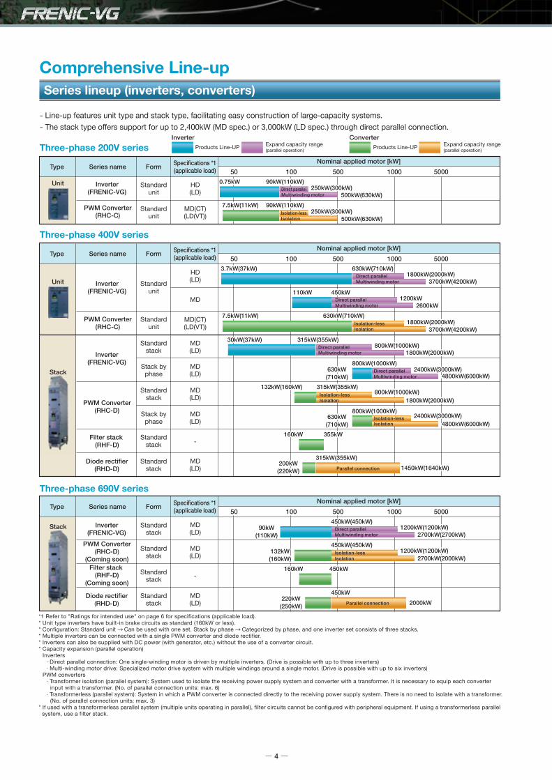
- Line-up features unit type and stack type, facilitating easy construction of large-capacity systems.
- The stack type offers support for up to 2,400kW (MD spec.) or 3,000kW (LD spec.) through direct parallel connection.
Isolation-lessIsolation
Multiwinding motor
Parallel connection
630kW(710kW)630kW(710kW)
800kW(1000kW)800kW(1000kW)2400kW(3000kW)2400kW(3000kW)
Direct parallel
Inverter ConverterProducts Line-UP Products Line-UPExpand capacity range
(parallel operation)Expand capacity range(parallel operation)
*1 Refer to "Ratings for intended use" on page 6 for specifications (applicable load).* Unit type inverters have built-in brake circuits as standard (160kW or less).* Configuration: Standard unit Can be used with one set. Stack by phase Categorized by phase, and one inverter set consists of three stacks.* Multiple inverters can be connected with a single PWM converter and diode rectifier.* Inverters can also be supplied with DC power (with generator, etc.) without the use of a converter circuit.* Capacity expansion (parallel operation) Inverters · Direct parallel connection: One single-winding motor is driven by multiple inverters. (Drive is possible with up to three inverters) · Multi-winding motor drive: Specialized motor drive system with multiple windings around a single motor. (Drive is possible with up to six inverters) PWM converters · Transformer isolation (parallel system): System used to isolate the receiving power supply system and converter with a transformer. It is necessary to equip each converter input with a transformer. (No. of parallel connection units: max. 6) · Transformerless (parallel system): System in which a PWM converter is connected directly to the receiving power supply system. There is no need to isolate with a transformer. (No. of parallel connection units: max. 3)* If used with a transformerless parallel system (multiple units operating in parallel), filter circuits cannot be configured with peripheral equipment. If using a transformerless parallel system, use a filter stack.
4

3.7kW(37kW) 630kW(710kW)1800kW(2000kW)
7.5kW(11kW)
30kW(37kW)
132kW(160kW) 315kW(355kW)
315kW(355kW)200kW
(220kW)
355kW160kW
1450kW(1640kW)
630kW(710kW)
800kW(1000kW)2400kW(3000kW)
4800kW(6000kW)
800kW(1000kW)
1200kW(1200kW)
1800kW(2000kW)
315kW(355kW)800kW(1000kW)
4800kW(6000kW)4800kW(6000kW)4800kW(6000kW)4800kW(6000kW)
630kW(710kW)1800kW(2000kW)
3700kW(4200kW)
1800kW(2000kW)
3700kW(4200kW)
110kW 450kW1200kW
2600kW
90kW(110kW)
132kW(160kW)
450kW(450kW)
450kW220kW
(250kW)
450kW160kW
2000kW
1200kW(1200kW)
450kW(450kW)
2700kW(2700kW)
2700kW(2000kW)
0.75kW 90kW(110kW)250kW(300kW)
7.5kW(11kW) 90kW(110kW)250kW(300kW)
500kW(630kW)
500kW(630kW)
630kW(710kW)
800kW(1000kW)2400kW(3000kW)
Realizes the industry-leading control performance
Improved Control Performance
Induction motor
* Compared with our conventional models
Achieved speed responseof 600 Hz Follow-up characteristics
under impact load
Uneven rotationreduced by one-third
Speed and torque characteristicsUnder vector control with sensor
0.0deg
Torque currentcommand value
Actual speedvalue
Motor current
-360deg
Phase(deg)
25.0dB
-25.0dB
dBMg
100010010Frequency Hz
Frequency Hz
FRN7.5VG1S-2J(600Hz, -3dB)FRN7.5VG7S-2(105Hz, -3dB)FRN7.5VG5S-2(54Hz, -3dB)
FRN37VG1S-4J, at 500r/min operation
at 30r/min operation FRN37VG1S-4J
1
1000100101
100%
100r/min
0.5r/min
Load ON(100%) Load OFF(0%)0.5s
150100 50 0-50
-100-150
1000 2000 3000Rotation speed(r/min)
Axia
l tor
que
(%)
0.5r/min
* With the stack type, "100 Hz" is achieved.
FRN37VG1S-4J
Conventional model FRN37VG7S-4
(Tested with a dedicated motor with PG under vector control withspeed sensor: about six times greater than our conventional model)
5

A Wide Range of Applications
A standard built-in brake circuit with expanded capacity range
High-speed, high-accuracy position control realized (servo function)
Control method
- Built-in position control function as standard with pulse train input (A separate option (OPC-VG1-PG(PR)) is required for pulse train input.)- High-speed, high-accuracy position control is possible in combination with
an E-SX bus and 17-bit high-resolution ABS encoder. (The servo function is supported with a dedicated type.) (Soon to be supported)
Having a standard built-in brake circuit (with 200V 55kW or less and 400V 160KW or less), is useful when applying the inverter to the vertical transfer machine, which is frequently used under the regenerative load.* Unit type only
Ratings for intended useThe operation mode for the motor is selected according to motor load condition. Motors larger by one or two frames can be driven with medium load (MD) and light load (LD) use.
*1 This varies depending on motor specifications and power supply voltage.*2 Carrier frequency becomes 2kHz.
Specification Applied load Feature Applicable overload ratingPower supply
voltageApplicable motor capacity [kW]
Unit Type Stack Type*2
HD
MD
LD
High DutySpec
Middle DutySpec
Low DutySpec
Powerful drive at low noise
Can drive motors of framesone size larger *1
Can drive motors of framesone or two sizes larger *1
Current: 150% 1min/200% 3sec
150% 1min
Unit type:120% 1minStack type:110% 1min
200V
400V
690V
200V
400V
690V
200V
400V
690V
0.75 to 90
3.7 to 630
-
-
110 to 450 *2
-
37 to 110
37 to 710
-
-
-
-
-
30 to 800
90 to 450
-
37 to 1000
110 to 450
RHCfilter circuit
RHC-Cunit
VG7 unit(280kW)
VG7 unit(55kW)
VG7 unit(45kW x 4)
A wide range of options
- Providing options supporting various interfaces such as high-speed serial communications- Options can be used by just inserting them into the connectors inside the inverter. Up to four cards can be mounted. (Combination with built-in control option: see page 48)
Induction motor-Vector control with speed sensor-Speed sensorless vector control-V/f Control
- Vector control with speed sensor (including pole position detection)
Control methodTarget motors
Synchronous motor
Categoly Name Type
Synchronized interfaceF/V converter*1Analog input/output interface expansion cardDi interface cardDio extension cardPG interface card
PG card for synchronous motor drive
T-Link communication cardCC-Link communication cardHigh-speed serial communication card (for UPAC)*1SX bus communication cardE-SX bus communication cardUser programming cardPROFINET-IRT communication cardFunctional safety cardPROFIBUS-DP communication cardDeviceNet communication cardTerminal block for high-speed communications
+5V line driverOpen collectorABS encoder with 17-bit high resolutionLine driverOpen collector
OPC-VG1-SNOPC-VG1-FVOPC-VG1-AIOOPC-VG1-DIOPC-VG1-DIOOPC-VG1-PGOPC-VG1-PGoOPC-VG1-SPGT OPC-VG1-PMPGOPC-VG1-PMPGoOPC-VG1-TLOPC-VG1-CCLOPC-VG1-SIUOPC-VG1-SXOPC-VG1-ESXOPC-VG1-UPACOPC-VG1-PNETOPC-VG1-SAFEOPC-VG1-PDPOPC-VG1-DEVOPC-VG1-TBSI
*1 comming soon
Not only the induction motors but also the synchronous motors can be driven, and for the induction motors, you can select the most suitable control method according to your individual needs.
Analog card
Digital card (for 8-bit bus)
Digital card (for 16-bit bus)
Safety card
Field bus interface card
Control circuit terminal
6

Dedicated design for panel installation (Stack Type)
The use of a stack type designed specifically for panel installation has resulted in a reduced panel size compared with the conventional design.A 34% reduction in panel width has been achieved over the conventional design (example for crane system).The dedicated design has also resulted in easier installation of products into the panel and easier replacement.
RH
C-C
+V
G7S
New
:RH
C-D
+R
HF-
D+
VG
(Sta
ck)
RHCfilter circuit
RHCfilter circuit
RHC-Cunit
RHC-Cunit
VG7 unit(280kW)VG7 unit(280kW)
VG7 unit(55kW)
VG7 unit(55kW)
VG7 unit(45kW x 4)VG7 unit
(45kW x 4)
1200 1200 1200800
1150 1100500
500 600
600500
Width size-34%
Panel size reduction realized
<Panel configuration example for crane system>
7

SiC-SBD
Fuji handles all processes from new development to production from the device level, and has realized an optimized SiC module design tailored to stacks. This has resulted in a 28% reduction in generated loss, facilitated a reduction in stack size, and allowed capacity to be expanded.
690V Series Inverter Stack Capacity Expansion Through Adoption of SiC Hybrid Module (355 /400/450kW)
Adoption of next-generation device (SiC-SBD)
Through the adoption of an SiC hybrid module, generated loss has been reduced by 28%, and stack single unit capacity has been expanded to 450kW, while ensuring the same dimensions as stacks in the 250 to 315kW capacity range. (Stack width: 226.2 mm)
Compact size and capacity expansion through adoption of SiC hybrid module
VG stackSiC wafer processing
Stack width 226.2 mm x 2 stacks
[Conventional] [New product]
Stack width 226.2 mm
SiC hybridmodule
450kW x 1 stack
SiC hybrid module
315kW 450kWSingle unit
capacity
Stack width
Capacity
226.2mm
0.18m3
Dimensions and capacity comparison
NEW
*1 The capacity expansion value indicates the nominal applied motor capacity.*2 Capacity expansion applies to the direct parallel connection system. Up to three inverters can be connected in parallel.
Also compatible with fan, pump applications
- Forced operation (Fire Mode) The inverter protection function is ignored (retry), allowing operation to be continued. This allows fans and pumps to continue running as much as possible in times of emergency such as when there is a fire.- Command loss detection function If analog speed setting signals are interrupted, operation continues at the speed set with a function code.- Low water quantity stop function The inverter can be stopped if the pump discharge pressure rises and discharged water quantity drops.- Broad capacity range Capacity expansion is easy with parallel operation (direct parallel connection).
Applicable for even large-scale systems with dedicated fan and pump functions and broad capacity range [Soon to be supported]
Power supply voltageLineup Capacity expansion *1 No. of parallel units *2 Lineup Capacity expansion *1 No. of parallel units *2
Unit type: HD spec./Stack type: MD spec. LD specificationForm
Up to 90kWUp to 630kWUp to 800kWUp to 450kW
Up to 250kWUp to 1800kWUp to 2400kWUp to 1200kW
3333
Up to 110kWUp to 710kW
Up to 1000kWUp to 450kW
Up to 300kWUp to 2000kWUp to 3000kWUp to 1200kW
3333
Unit type
Stack type
200V series
400V series
400V series
690V series
Si(conventional)
SiC hybrid
28% loss reduction
[with 450kW application]
100%
75%
50%
25%
0%
(conventional)
SiC-SBD Si-IGBT
SiC hybridmodule
Use of a "single" 450kW system configuration realized with SiC hybrid module application
Loss
8

Wheels
IM
U,V,W
P
N
IM
U,V,W
P
N
U-phase V-phase W-phase
M
P
N
Fault
Lifter (Conceptual view)
Easier maintenanceInverter product range and ease of replacement (stack type)
The inverters (stack type) have an arrangement with consideration for the installation of the product into the panel and easier change.The inverters (stack type) (132 to 315 kW) can easily be installed or changed because they have wheels.With the inverters (stack type) (630 to 800 kW), stacks are divided for each output phase (U, V and W), which has realized the lighter weight.
A PLC (MICREX-SX Series: SPH3000MM) and FRENIC-VG can be connected with the ultrahigh-speed communication E-SX bus. With ultrahigh-speed communication, support is possible for even faster, more accurate devices.
Support for ultrahigh-speed E-SX bus
Type
Categoly Single unit Single unit Stack by phase
Approx.weight [kg] 30 to 45 95 to 135 135×3
30 to 110 132 to 450 630 to 800Nominal applied motor capacity[kW] (MD spec)
Arrangement
Maintenance
400V: FRN30SVG1S-4 to FRN110SVG1S-4
690V: FRN90SVG1S-69 to FRN110SVG1S-69
400V: FRN132SVG1S-4 to FRN315SVG1S-4
690V: FRN132SVG1S-69 to FRN450SVG1S-69
FRN630BVG1S-4 toFRN800BVG1S-4
Provided ProvidedNot provided
The weight of one stack is reduced (50 kg or less) to give consideration to replacement work.
The models where each stack is heavy have wheels in order to change the stacks easily.A lifter for replacement is available.
Trim weight by dividing the stack into 3 parts by each output phase (U, V and W). In the event of a breakdown, only the target phase needs to be replaced with a new one.The stack to be replaced should be an exclusive part.
9
h ultrahigh-speed communication, support is possible foC (MICREX-SX Series: Sultrahigh-speed commu
E-SX bus
E-SX bus
Distance between stations: 100 m
Baud rate: 100 Mbps
Total extension distance: 1,000 m

- Wide 7-segment LED ensures easy view.- The back-light is incorporated in the LCD panel, which enables the easy inspection in the dark
control panel.- Enhanced copy function
The function codes can be copied to other inverters easily. (Three patterns of function codes can be stored.) Copying data in advance reduces restoration time when problems occur, by replacing the Keypad when changing the inverter.
- Remote control operation is available.The Keypad can be remotely operated by extending the cable length at the RJ-45 connector.
- JOG (jogging) operation can be executed using the Keypad.- The HELP key displays operation guidance.- Supported languages: English, Chinese, Korean (Hangul), Japanese
Multifunctional the Keypad
FRENIC-VG
USB cable
USB Mini Bconnector
Connection availablein the inverter front.
PC
Upgraded PC loader functions
Easier Maintenance and Greater Reliability
- Internal data, time and date around the fault are recorded.The real-time clock (clock function) is built-in as standard.
- Data are backed up by battery.Trace data can be stored in the memory even while the power is off.*Battery: 30kW or more (built-in as standard), up to 22kW (available as option: OPK-BP)
- Trace waveform can be checked on the PC loader
PC Loader can be used via the USB connector (mini B) provided on the front cover.
[Fault diagnosis using the trace back function]
- The front cover does not have to be removed.
- No RS-485 converter is needed.
- Commercial cables can be used.
Edited on the trace screen on the loader Data editing and detailed data monitor analysis operations are much easier than with a conventional PC loader.
User-defined displays (customized displays), data explanation display for each code.
Function code setting
Real-time trace: for long-term monitoringHistorical trace: for detailed data diagnosis for short periodsTrace back: for fault analysis (last three times)
Trace function
[Easy edit and detail monitor]
*The paid-for loader software (WPS-VG1-PCL) supports real-time tracing and historical tracing.
*The paid-for loader software (WPS-VG1-STR) is contained in the CD-ROM provided with the product. (Can be downloaded from the Fuji website.)
10

Time of occurrence2011/01/0112:36:45
N*=1500.0r/mN =1500.0r/mf *=50.0HzTRQ= 90%
TMP = 43℃Iout = 251.6AVout = 190VFLX*= 100%
Time of occurrence2011/01/0112:36:45
N*=1500.0r/mN =1500.0r/mf *=50.0HzTRQ= 90%
TMP = 35℃Iout = 256.2AVout = 200VFLX*= 100%
Time of occurrence2011/01/0212:36:45
N*=1500.0r/mN =1500.0r/mf *=50.0HzTRQ= 90%
TMP = 55℃Iout = 180.0AVout = 132VFLX*= 100%
Time of occurrence2011/01/0512:36:45
N*=1500.0r/mN =1500.0r/mf *=50.0HzTRQ= 90%
TMP = 45℃Iout = 210.6AVout = 160VFLX*= 100%
Easy change of the cooling fan
The cooling fan can easily be changed without removing the front cover and printed board.
The cooling fan installed at the top can easily be changed without drawing the stacks. However, for the 220kW or above inverter, remove the 2 connection bars from the DC side and change the cooling fan.
Unit Type
Stack Type Inverter body Fan body
Inverter body Fan body
More reliable functions
Motor overload, communications error,DC fan lock, etc.
Blown fuse, excessive current,ground fault, etc.
30-relayoutput
Y-terminaloutput
Inverteroutput
Selection
No output(minor fault)
Output
Output
Not provided
Provided
Not provided
Shut off
Operationcontinued
Shut off
Can be selectedfor each function.
Fixed
Alarm severity (serious and minor) can be selected, eliminating the risk of critical facility stoppage due to a minor fault.
- The number of alarm data to be stored has been increased from the conventional model. Thanks to the real-time clock function built-in as standard, the complete data of the latest and last 3 alarm occurences is stored: time, speed command, torque, current and others. This enables machine units to be checked for abnormalities.As for previous model, new alarm data overwrote and deleted existing alarm data. This is solved with the new VG model.
Alarm severity selection
- The PG interface circuit incorporated as standard detects disconnection of the power supply line as well as the PG signal line.
- A mode was added that judges if it is a PG fault or a fault on the inverter sideSimulated output mode is provided at the PG pulse output terminal (FA and FB). Operation can be checked by connecting this to the PG input terminal.
PG fault diagnosis
Save alarm data
OC
LU
OC
OU
- Time to sound alarm- Speed setting value- Detection speed value- Torque command value- Temperature (heat sink, internal temperature)
- Accumulated operation time- Output current detection value- Magnetic-flux reference value- I/O status
Detailed data are stored forthe last four alarms, including:
11

- The terminal block can be connected to the inverter after control wiring work is completed. Wiring work is simplified.- Restoration time for updating equipment, problem occurrence, and inverter replacement has been drastically reduced.
Just mount the wired terminal block board to the replaced inverter.
- Customization of functions for test run and adjustment (Individual items on the loader can be set to be displayed or not.)- Simulated fault alarm issued by a special function on the Keypad- Monitor data hold function- Simulated operation mode
Simulated connection allows the inverter to be operated with internal parts in the same way as if they were connected to the motor, without actually being connected.
- The externally input I/O monitor and PG pulse states can be checked on the Keypad.
Life conditions Unit type: ambient temperature 40 °C, load factor 100% (HD spec.), 80% (MD spec., LD spec.)Stack type: ambient temperature 30 °C, load factor 100% (MD spec.), 80% (LD spec.)*The planned life is determined by calculation, and is not the guaranteed value.
Life-limited component
Cooling fan
Smoothing capacitor on main circuit
Electrolytic capacitors on PCB
Design lifetime*
10 years
Components with a longer service life
Enhanced lifetime alarm
Items
Inverter accumulatedtime (h)
Facility maintenance warning Accumulated time (h)No. of starts (times)
No. of inverterstarts (times)
Inverter lifetimealarm information
is displayed.
- Lifetime alarms can be checked rapidly on the Keypad and PC loader (optional).
- Facility maintenance can be performed much easier thanks to lifetime alarms.
For the various consumable parts inside the inverter, their designed lives have been extended to 10 years.This also extended the equipment maintenance cycles.
Easy wiring (removable control terminal block)
Unit Type Stack Type
Useful functions for test run and adjustment
12

Applicable models : FRENIC-VG (Unit Type), FRENIC-VG (Stack type three-phase 400V series)
- Complies with UL and cUL Standards, EC Directives (CE marking), KC certification, and RoHS Directive.
- Directive when the standard model is combined with an option (EMC filter).
Adaptation to Environment and SafetyCompliance with overseas standards
Applicable models : FRENIC-VG (Unit Type), FRENIC-VG (Stack type three-phase 400V series)
- The functional safety (FS) function STO that conforms to the FS standard IEC/EN61800-5-2 is incorporated as standard.
- The FS functions STO, SS1, SLS and SBC that conform to FS standard IEC/EN61800-5-2 can be also available by installing the option card OPC-VG1-SAFE. (Available only when controlling the motor using feedback encoder (closed loop).)
Conforms to safety standards
Safety function STO: Safe Torque OffThis function shuts off the output of the inverter (motor output torque) immediately.
Safety function SS1: Safe Stop 1This function decreases the motor speed to shut down the motor output torque (by STO FS function) after the motor reaches the specified speed or after the specified time has elapsed.
Safety function SLS: Safely Limited SpeedThis function prevents the motor from rotating over the specified speed.
Safety function SBC: Safe Brake ControlThis function outputs a safe signal of the motor brake control.
US/Canada
UL Standards/cUL Standards
EU
EC Directive (CE marking)
KoreaKC certification
(Stack type: pending certification)
Environmental resistance has been enhanced compared to conventional inverters. (1) Environmental resistance of cooling fan has been enhanced. (2) Ni and Sn plating are employed on copper bars.
Contact Fuji before using the product in environments such as those indicated above.
Environmental resistance has been enhanced on the FRENIC-VG compared to conventional models; however, the following environments should be examined based on how the equipment is being used.a. Sulfidizing gas (present in some activities such as tire manufacturers,
paper manufacturers, sewage treatment, and the textile industry)
b. Conductive dust and foreign particles (such as with metal processing, extruding machines, printing machines, and waste treatment)
c. Others: under unique environments not included under standard environments
Enhanced environmental resistance
13

Number of inverters to be connected
Features
Arrangement diagram
IM
P
N
L
U,V,W U,V,W
P,N P,N
*1 *1
P
N
U,V,W U,V,W
P,N P,N
*1 *1
IM
IM
P
N
U,V,W U,V,W
P,N P,N
*1 *1
IM
P
N
P
N
U V
P,N P,NP,N
W
P,N
P
N
U V
P,N P,N
W
P,N
IM
U V
P,N P,N
W
P,N
*1 *1
IM
U,V,W
*1) OPC-VG1-TBSI is separately required.*2) Reduced capacity operation. If a stack fails in case of
direct parallel connection, the operation continues with lower output power using the stacks that have not failed.
(Note) To start the reduced capacity operation, consideration is needed to the switch over operation of PG signals or motor constants and sequence circuit. For details, refer to the operation manual.
I M
U,V,W U,V,W
200kW 200kW
355kW
Fault
How to expand the capacity range of the inverters (Stack Type)Direct parallel connection system and multiwinding motor drive system are provided for driving a large capacity motor.
System
Single-winding motor
Available
The minimum wiring length (L) varies with the capacity.
Multiwinding motor(Exclusive use for multiwinding motors)
Available(However, the wiring should be switched over.)
There is no particular limit.
Direct parallel connection system Multiwinding motor drive system
2 or even 3 inverters of the same capacity can be connected in parallel to increase capacity or facilitate system redundancy. Typical combinations are shown in Table 1, however, other configurations are also possible.
2 to 3 inverters 2 to 6 inverters
When 2 invertersare connected
When 2 invertersare connected
Table 1 Direct parallel combination example (400V series, MD specification)
*1) OPC-VG1-TBSI is required for each stack.
Connectionsystem
Capacity[kW]
Applicableinverter
No. ofunits
Current[A]
No. ofunits
Current[A]
Applicable inverterApplicable inverter Applicable inverter
FRN30SVG1FRN37SVG1FRN45SVG1FRN55SVG1FRN75SVG1FRN90SVG1FRN110SVG1FRN132SVG1FRN160SVG1FRN200SVG1FRN220SVG1FRN250SVG1FRN280SVG1FRN315SVG1
FRN630BVG1FRN710BVG1FRN800BVG1
FRN630BVG1FRN630BVG1FRN800BVG1FRN630BVG1FRN710BVG1FRN800BVG1
222333
2223 2223 2812 3335 3905 4218
FRN200SVG1FRN220SVG1FRN280SVG1FRN220SVG1FRN280SVG1FRN280SVG1
222333
716789988
118314821482
Standard stack Stack by phase
303745557590110132160200220250280315355400500630710800100012001500180020002400
Drive motor
Reduced capacityoperation *2
Restriction ofwiring length
Example) If one inverter fails when 200kW x 2 inverters are driving a 355kW motor, the operation can continue with the 200kW inverter (capacity of one inverter).
Configuration table for direct parallel connection
14
P
N
P,N P,N
*2 *2
Peripheralequipment
PWM Converter PWM Converter
Transformer
Power supply Power supply
Peripheralequipment
P
N
P,N P,N
*3 *3
Peripheralequipment
Three-windingtransformer(12 -pulse)
Peripheralequipment
Peripheralequipment
Peripheralequipment
TransformerTransformer
P
N
P,N P,N
*2 *2
P
NP
N
P,N P,NP,N
P,N
P
N
P,N P,N P,N P,N P,N P,N
*2 *2
Peripheralequipment Peripheral
equipment
Peripheralequipment
Peripheralequipment
Transformer
Power supply Power supply Power supply
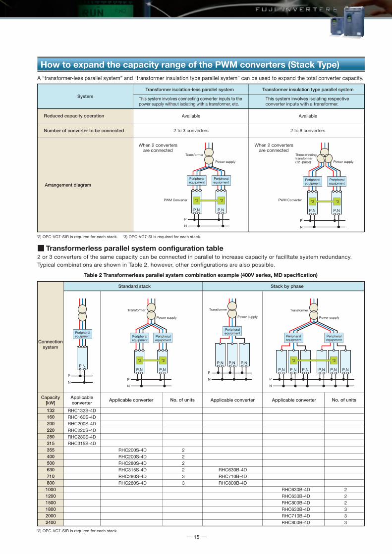
How to expand the capacity range of the PWM converters (Stack Type)A “transformer-less parallel system” and “transformer insulation type parallel system” can be used to expand the total converter capacity.
2 or 3 converters of the same capacity can be connected in parallel to increase capacity or facilltate system redundancy.Typical combinations are shown in Table 2, however, other configurations are also possible.
Table 2 Transformerless parallel system combination example (400V series, MD specification)
*2) OPC-VG7-SIR is required for each stack.
*2) OPC-VG7-SIR is required for each stack. *3) OPC-VG7-SI is required for each stack.
This system involves connecting converter inputs to the power supply without isolating with a transformer, etc.
This system involves isolating respective converter inputs with a transformer.
System
Reduced capacity operation
Number of converter to be connected
Available
2 to 3 converters
Available
2 to 6 converters
Transformer isolation-less parallel system Transformer insulation type parallel system
Arrangement diagram
When 2 convertersare connected
When 2 convertersare connected
Transformerless parallel system configuration table
Connectionsystem
Capacity[kW]
Applicableconverter
No. of units No. of unitsApplicable converterApplicable converter Applicable converter
RHC132S-4DRHC160S-4DRHC200S-4DRHC220S-4DRHC280S-4DRHC315S-4D
RHC630B-4DRHC710B-4DRHC800B-4D
RHC630B-4DRHC630B-4DRHC800B-4DRHC630B-4DRHC710B-4DRHC800B-4D
2 2 2 3 3 3
RHC200S-4DRHC200S-4DRHC280S-4DRHC315S-4DRHC280S-4DRHC280S-4D
2 2 2 2 3 3
Standard stack Stack by phase
132160200220280315355400500630710800100012001500180020002400
15

SISIRTBSI
F C ITBSI
F C ITBSI
F C ITBSI
F C ITBSI
SI
SI
F C ITBSI
F C ITBSI
F C ITBSI
F C ITBSI
F C ITBSI
F C ITBSI
F C ITBSI
F C ITBSI
F C ISIR
SIR
TBSI
F C ITBSI
SIR
SIR
F C ITBSI
F C ITBSI
F C ITBSI
ITBSI
F C ITBSI
ITBSI
F C I
System Configuration Overview
Filter circuit (individual)or filter stack
Converter unit(RHC-C) orstack(RHC-D) Inverter unit or stack Optical communication card
(option)
Note
(*1) The filter stack (RHF-D) is for exclusive use with the PWM converter (RHC-D) stack type. It cannot be used with the PWM converter (RHC-C) unit type.(*2) Please note that restrictions apply if using an RHC Series filter (available separately) with the PWM converter (RHC-D) stack type. For details, contact Fuji.(Note 1) If using with a direct parallel connection or multi-winding motor drive, ensure that the capacity is the same for all inverters.(Note 2) When multiple inverters are powered by a single converter, ensure that the converter capacity ≥ the total inverter capacity.(Note 3) When driving a motor with direct parallel connection, a minimum wiring length between the motor and inverter should be maintained.(Note 4) The main power supply to all converters should be turned on at the same time.
System structureNo.
1
2
3
4
5
6
7
8
9
10
System construction
Available
CNV: 6 pieces/maxINV: 6 parallel connection/max
Available
CNV: 6 parallel connection/maxINV: 3 parallel connection/max
Available
CNV: 6 pieces/maxINV: 6 parallel connection/max
Available
INV: 6 parallel connection/max
Available
INV: 3 parallel connection/max
Available
CNV: 3 parallel connection/maxINV: 6 parallel connection/max
Available
CNV: 3 parallel connection/maxINV: 3 parallel connection/max
(Use No.3 for direct parallel connection.)
Not available
(If sharing converter output, use the No.7 connection.)
Not available
(If sharing converter output, use the No.8 connection.)
Not available
Filter stack(RHF)(*1)
Available
Available
Available
Available
Available
Available
Available
Filter for RHC-C series(individual type)
Motor capacity(Ex. FRN315SVG1S-4
parallel use)
to 1800kW(6 winding motor)
to 1800kW(6 winding motor)
to CNV capacity
to CNV capacity
to 1800kW(6 winding motor)
to 800kW(INV: 3 parallel
connection)
to 800kW(INV: 3 parallel
connection)
Converter unit (RHC-C) AvailableConverter stack (RHC-D)•RHC132S to 315S-4D Not Available (*2)•RHC630B to 800B-4D Available
Converter unit (RHC-C) AvailableConverter stack (RHC-D)•RHC132S to 315S-4D Not Available (*2)•RHC630B to 800B-4D Available
Converter unit (RHC-C) AvailableConverter stack (RHC-D)•RHC132S to 315S-4D Not Available (*2)•RHC630B to 800B-4D Available
PWM converter + inverter
Transformer(multi phase) Single winding motorPower Supply Multi winding motor CNV: PWM converter
INV: inverter
16

ACR
ACR
ACR
ACR
ACR
ACR
ACR
ACR
IRFI
IRFI
IRFI
or
or
or
ITBSI
TBSI
I
ITBSI
TBSI
I
ITBSI
TBSI
I
RFI
RFI
RFI
RFI
RFI
ITBSI
TBSI
I
RFI
ITBSI
RFI
ITBSI
RFI
ITBSI
RFI
ITBSI
RFI
ITBSI
RFI
RFI
TBSI
IRFI
TBSI
IRFI
ITBSI
TBSI
I
RFI
RFI
or
ACR
Transformer (12 phase)
I Inverter unit or stack
Single winding motor
RFI Diode rectifier
Power Supply
TBSI Optical communication card (option)
Multi winding motorNote
AC reactor
INV: inverter
No.
1
2
3
4
5
6
7
(*1) Motor capacity is calculated based on a power supply voltage of 400 V.(Note 1) Use inverters of the same capacity for direct parallel systems and multiwinding motor drive systems.(Note 2) Turn ON the main power supply for all converters at the same time.
System structure Remarks
RFI:INV= 1:N
RFI:INV= 2:2RFI:INV= 3:3
RFI:INV= 2:NRFI:INV= 3:N
RFI:INV= 2:2
RFI:INV= 2:N
RFI:INV= 4:N
RFI:INV= 6:N
Applicable systemApplicable motor capacity
(total) (*1)
Direct parallel systemMultiwinding system
Continous rating (total)MD: to 315kWLD: to 355kW
Multiwinding system
Continous rating (total)MD: to 945kWLD: to 1065kW
Direct parallel systemMultiwinding system
Continous rating (total)MD: to 869kWLD: to 979kW
Multiwinding system
Continous rating (total)MD: to 548kWLD: to 617kW
Direct parallel systemMultiwinding system
Continous rating (total)MD: to 548kWLD: to 617kW
Direct parallel systemMultiwinding system
Continous rating (total)MD: to 970kWLD: to 1093kW
If using RFI (x4, or 6) structure configuration
Direct parallel systemMultiwinding system
Continous rating (total)MD: to 1450kWLD: to 1640kW
If using RFI (x6) structure
1) If common bus not applied for RFI output (DC output)
2) Not applicable with direct parallel systems
1) If common bus not applied for RFI output (DC output)
2) Not applicable with direct parallel systems
3) Voltage distortion in input voltage (3%, from IEC standards)
4) Use an AC reactor.
1) Voltage distortion in input voltage (3%, from IEC standards)
2) Use an AC reactor.
1) A common bus should be applied for RFI output (DC output).
2) Restrictions apply to wiring conditions from TR to INV.
3) Voltage distortion in input voltage (3%, from IEC standards)
4) Wiring restrictions apply from input power supply to DC common bus.
1) A common bus should be applied for RFI output (DC output).
2) Restrictions apply to wiring conditions from Transformer to Inverter.
3) Voltage distortion in input voltage (3%, from IEC standards)
4) Use an AC reactor.
1) A common bus should be applied for RFI output (DC output).
2) Restrictions apply to wiring conditions from Transformer to Inverter.
3) Voltage distortion in input voltage (3%, from IEC standards)
4) Use an AC reactor.
Diode Rectifier (RHD-D) + inverter
17

Application Examples
18
Position controlThe press position is controlled based on an instantaneous position command given by the upper order CNC.Control with high responsibility contributes to shortening of the operation cycle.
Precision synchronization controlLarge machines are driven with several motors to increase thrust.Precision synchronization control of several inverters and motors using the high-speed bus system can be applied.
Tension controlTension-type winding control capability with high accuracy torque control has been improved.Dancer-type winding control capability by the speed control with high speed response has been improved.
System support The controller that calculates winding diameter achieves constant tension control.
Winding equipment (paper and metal)
Application to plants
High reliabilityVG supports your facility with long life service and high reliability.The trace back function allows easy fault diagnosis.
Bus system supportThe bus system is supported to allow centralized control of elevation, traverse, and trolley, as well as centralized monitoring of running conditions.
Control with high speed and high accuracy In addition to high speed and high accuracy, VG contributes to stable facility operation with high reliability and long service life. The trace back function makes diagnosing the cause of problems easy when an abnormality arises.
Bus system supportCentralized control and monitoring are achieved by supporting various fieldbuses.
Large crane andoverhead crane
Electric room
Operationroom
Container
Travel equipment
Monitoring room
Servo press: large size for automobiles, small size for machines such as crimping terminal processing machines

19
Position controlPosition control is performed according to the position command given by the upper order CNC.The machine cuts the material while moving at the same speed (as the material).
System supportThe system is configured by an upper controller that calculates synchronous operation between the material feed axis, cutter feed axis and cut axis.
Feeding part of semiconductormanufacturing device, wire saw
Smooth torque characteristic The smooth drive characteristic in which torque ripple is suppressed contributes to machining quality.
System supportThe system becomes more simple and highly efficient by using same bus system for main axis (spindle) and the other axes (traverse and winding) driven by small capacity servos.
Shipboard winch
Test equipmentfor automobiles
High-speed response controlHigh-speed rotation and torque control with high response are available for engine and transmission tests.
System support The system can be supported in cases such as the vehicle body inertia simulation function for a brake test apparatus by combining with the controller.
High reliability and tension controlTorque is controlled up to extra low speed using the sensorless feature.Stable drive is maintained against load variation caused by waves.
Feed
Material
MM
M M
MM
M
M
main SpindleTraverse
TraverseDancer
Dancer
winder
unwinder
Flying shear(Cutting while moving)
Model variation (Inverter)
FRN0.75VG1S-2
FRN1.5VG1S-2
FRN2.2VG1S-2
FRN3.7VG1S-2
FRN5.5VG1S-2
FRN7.5VG1S-2
FRN11VG1S-2
FRN15VG1S-2
FRN18.5VG1S-2
FRN22VG1S-2
FRN30VG1S-2
FRN37VG1S-2
FRN45VG1S-2
FRN55VG1S-2
FRN75VG1S-2
FRN90VG1S-2
FRN3.7VG1S-4
FRN5.5VG1S-4
FRN7.5VG1S-4
FRN11VG1S-4
FRN15VG1S-4
FRN18.5VG1S-4
FRN22VG1S-4
FRN30VG1S-4
FRN37VG1S-4
FRN45VG1S-4
FRN55VG1S-4
FRN75VG1S-4
FRN90VG1S-4
FRN110VG1S-4
FRN132VG1S-4
FRN160VG1S-4
FRN200VG1S-4
FRN220VG1S-4
FRN280VG1S-4
FRN315VG1S-4
FRN355VG1S-4
FRN400VG1S-4
FRN500VG1S-4
FRN630VG1S-4
FRN30VG1S-2
FRN37VG1S-2
FRN45VG1S-2
FRN55VG1S-2
FRN75VG1S-2
FRN90VG1S-2 FRN90VG1S-4
FRN110VG1S-4
FRN132VG1S-4
FRN160VG1S-4
FRN200VG1S-4
FRN220VG1S-4
FRN280VG1S-4
FRN315VG1S-4
FRN355VG1S-4
FRN400VG1S-4
FRN30VG1S-4
FRN37VG1S-4
FRN45VG1S-4
FRN55VG1S-4
FRN75VG1S-4
FRN90VG1S-4
FRN110VG1S-4
FRN132VG1S-4
FRN160VG1S-4
FRN200VG1S-4
FRN220VG1S-4
FRN280VG1S-4
FRN315VG1S-4
FRN355VG1S-4
FRN400VG1S-4
FRN500VG1S-4
FRN630VG1S-4
HD(150%, 1 min./200%, 3 sec.)
Nominal applied motor(kW)
Applied load High Duty Spec High Duty SpecLow Duty Spec Low Duty SpecMiddle Duty Spec
LD(120%, 1 min.)
HD(150%, 1 min./200%, 3 sec.)
MD(150%, 1 min.)
LD(120%, 1 min.)
Unit Type Unit Type
200V Series 400V Series
0.75
1.5
2.2
3.7
5.5
7.5
11
15
18.5
22
30
37
45
55
75
90
110
132
160
200
220
250
280
315
355
400
450
500
630
710
800
1000
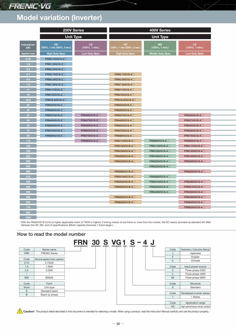
* With the FRN55VG1S-2J/4J or higher (applicable motor of 75kW or higher), if driving motors of one frame or more from the inverter, the DC reactor provided as standard will differ between the HD, MD, and LD specifications. (Motor capacity becomes 1 frame larger.)
Caution! The product detail described in this document is intended for selecting a model. When using a product, read the Instruction Manual carefully and use the product properly.
FRN 30 VG 1 S 4 J-SCodeFRN
Series nameFRENIC Series
CodeJEC
Destination / Instruction ManualJapaneseEnglishChinese
CodeS
StructureStandard
Code24
69
Input power sourceThree-phase 200VThree-phase 400VThree-phase 690V
CodeNone
SB
FormUnit type
Standard stackStack by phase
Code0.751.52.2
800
Nominal applied motor capacity0.75kW1.5kW2.2kW
800kW
How to read the model number
CodeVG
Application rangeHigh performance vector control
Code1
Developed inverter series1 Series
20

FRN30SVG1S-4
FRN37SVG1S-4
FRN45SVG1S-4
FRN55SVG1S-4
FRN75SVG1S-4
FRN90SVG1S-4
FRN110SVG1S-4
FRN132SVG1S-4
FRN160SVG1S-4
FRN200SVG1S-4
FRN220SVG1S-4
FRN250SVG1S-4
FRN280SVG1S-4
FRN315SVG1S-4
FRN630BVG1S-4
FRN710BVG1S-4
FRN800BVG1S-4
FRN30SVG1S-4
FRN37SVG1S-4
FRN45SVG1S-4
FRN55SVG1S-4
FRN75SVG1S-4
FRN90SVG1S-4
FRN110SVG1S-4
FRN132SVG1S-4
FRN160SVG1S-4
FRN200SVG1S-4
FRN220SVG1S-4
FRN250SVG1S-4
FRN280SVG1S-4
FRN315SVG1S-4
FRN630BVG1S-4
FRN710BVG1S-4
FRN800BVG1S-4
Low Duty SpecMiddle Duty Spec
MD(150%, 1 min.)
LD(110%, 1 min.)
Stack Type
FRN90SVG1S-69
FRN110SVG1S-69
FRN132SVG1S-69
FRN160SVG1S-69
FRN200SVG1S-69
FRN250SVG1S-69
FRN280SVG1S-69
FRN315SVG1S-69
FRN355SVG1S-69
FRN400SVG1S-69
FRN450SVG1S-69
FRN90SVG1S-69
FRN110SVG1S-69
FRN132SVG1S-69
FRN160SVG1S-69
FRN200SVG1S-69
FRN250SVG1S-69
FRN280SVG1S-69
FRN315SVG1S-69
FRN355SVG1S-69
FRN400SVG1S-69
Low Duty SpecMiddle Duty Spec
MD(150%, 1 min.)
LD(110%, 1 min.)
Stack Type
400V Series 690V Series
Nominal applied motor(kW)
Applied load
0.75
1.5
2.2
3.7
5.5
7.5
11
15
18.5
22
30
37
45
55
75
90
110
132
160
200
220
250
280
315
355
400
450
500
630
710
800
1000
21

Model variation (converter)
RHC7.5-2C
RHC11-2C
RHC15-2C
RHC18.5-2C
RHC22-2C
RHC30-2C
RHC37-2C
RHC45-2C
RHC55-2C
RHC75-2C
RHC90-2C
RHC7.5-4C
RHC11-4C
RHC15-4C
RHC18.5-4C
RHC22-4C
RHC30-4C
RHC37-4C
RHC45-4C
RHC55-4C
RHC75-4C
RHC90-4C
RHC110-4C
RHC132-4C
RHC160-4C
RHC200-4C
RHC220-4C
RHC280-4C
RHC315-4C
RHC355-4C
RHC400-4C
RHC500-4C
RHC630-4C
RHC7.5-2C
RHC11-2C
RHC15-2C
RHC18.5-2C
RHC22-2C
RHC30-2C
RHC37-2C
RHC45-2C
RHC55-2C
RHC75-2C
RHC90-2C
RHC7.5-4C
RHC11-4C
RHC15-4C
RHC18.5-4C
RHC22-4C
RHC30-4C
RHC37-4C
RHC45-4C
RHC55-4C
RHC75-4C
RHC90-4C
RHC110-4C
RHC132-4C
RHC160-4C
RHC200-4C
RHC220-4C
RHC280-4C
RHC315-4C
RHC355-4C
RHC400-4C
HD(CT)(150%, 1 min.)
Nominal applied motor(kW)
Applied load High Duty Spec High Duty SpecLow Duty Spec Low Duty Spec
LD(VT)(120%, 1 min.)
HD(CT)(150%, 1 min.)
LD(VT)(120%, 1 min.)
Unit Type (PWM) Unit Type (PWM)
200V Series 400V Series
7.5
11
15
18.5
22
30
37
45
55
75
90
110
132
160
200
220
250
280
315
355
400
450
500
630
710
800
1000
RHC132S-4D
RHC160S-4D
RHC200S-4D
RHC220S-4D
RHC280S-4D
RHC315S-4D
RHC630B-4D
RHC710B-4D
RHC800B-4D
RHC132S-4D
RHC160S-4D
RHC200S-4D
RHC280S-4D
RHC315S-4D
RHC630B-4D
RHC710B-4D
RHC800B-4D
Middle Duty Spec
MD(150%, 1 min.)
RHF160S-4D
RHF160S-4D
RHF220S-4D
RHF220S-4D
RHF280S-4D
RHF355S-4D
RHF355S-4D
Low Duty Spec
LD(110%, 1 min.)
-
Dedicated RHC-D filter
Stack Type (PWM) Filter stack
Caution! The product detail described in this document is intended for selecting a model. When using a product, read the Instruction Manual carefully and use the product properly.
CodeRHCRHDRHF
Series namePMW converterDiode rectifier
Filter stack
Code24
69
Input power sourceThree-phase 200VThree-phase 400VThree-phase 690V
CodeCD
Developed inverter seriesC SeriesD Series
CodeNone
SB
FormUnit type
Standard stackStack by phase
RHC 315 4 DS - J
Code132
800
Nominal applied motor capacity132kW
800kW
Description of converter type
CodeJEC
Destination / Instruction ManualJapaneseEnglishChinese
22

400V Series 690V Series
Nominal applied motor(kW)
Applied load
7.5
11
15
18.5
22
30
37
45
55
75
90
110
132
160
200
220
250
280
315
355
400
450
500
630
710
800
1000
RHD200S-4D
RHD315S-4D
RHD200S-4D
RHD315S-4D
Middle Duty Spec
MD(150%, 1 min.)
Low Duty Spec
LD(110%, 1 min.)
Diode rectifier
RHD220S-69D
RHD450S-69D
RHD220S-69D
Middle Duty Spec
MD(150%, 1 min.)
Low Duty Spec
LD(110%, 1 min.)
Diode rectifier
RHC132S-69D
RHC160S-69D
RHC200S-69D
RHC250S-69D
RHC280S-69D
RHC315S-69D
RHC355S-69D
RHC400S-69D
RHC450S-69D
RHC132S-69D
RHC160S-69D
RHC200S-69D
RHC250S-69D
RHC280S-69D
RHC315S-69D
RHC355S-69D
RHC400S-69D
Middle Duty Spec
MD(150%, 1 min.)
RHF160S-69D
RHF160S-69D
RHF220S-69D
RHF220S-69D
RHF280S-69D
RHF280S-69D
RHF355S-69D
RHF355S-69D
RHF450S-69D
RHF450S-69D
-
Dedicated RHC-D filter
Low Duty Spec
LD(110%, 1 min.)
Stack Type (PWM)(Coming soon) Filter stack (Coming soon)
23

Standard specifications
24
HD specification for heavy overload (Unit Type)
Three-phase 200V seriesType FRN VG1S-2 0.75 1.5 2.2 3.7 5.5 7.5 11 15 18.5 22 30 37 45 55 75 90
Nominal applied motor [kW]Rated capacity [kVA] (*1)Rated current [A]Overload current rating
Nominal applied motor [kW] Rated capacity [kVA] (*1)Rated current [A]Overload current rating
Braking method /braking torqueCarrier frequency [kHz] (*9)Approx.weight [kg]Enclosure
Braking method /braking torqueCarrier frequency [kHz] (*9)Approx.weight [kg]Enclosure
Main powerPhase, Voltage, Frequency
Auxiliary control power supplyPhase, Voltage, Frequency
Auxiliary input for fan powerPhase, Voltage, Frequency (*5)Voltage/frequency variation
Rated current [A] (*7)
Required power supply capacity [kVA] (*8)
0.751.95
1.53.08
2.24.111
3.76.818
5.51027
7.51437
111849
152463
18.52876
223490
3045
119
3755
146
4568
180
5581
215
75107283
90131346
3.25.31.2
7.513.05.2
10.617.37.4
14.423.210
21.13315
28.843.820
35.552.325
42.260.630
57.077.940
68.594.348
83.211458
10214071
138−96
164 −
114
210 −
140
238 −
165
286 −
199
357 −
248
390 −
271
500 −
347
559 −
388
628−
436
705 −
489
881 −
610
1115 −
773
6.19.52.2
8.913.23.1
15.022.25.2
21.131.57.4
28.842.710
42.260.715
57.680.120
71.097.025
84.411230
11415140
13818548
16722558
20327071
282−98
334−
116
6.2
6.2 6.2 6.2 11 11 11 11 25 26 31 33 42 62 64 94 98 129 140 245 245 330 330 555 555
6.2 6.2 6.2 6.2 6.2 11 11 11 12 25 32 42 43 62 105
−
3-phase 200 to 230V, 50Hz/60Hz
Single-phase 200 to 230V, 50Hz/60Hz
3.76.89.0
5.510
13.5
7.514
18.5
1118
24.5
1524
32.0
18.529
39.0
2234
45.0
3045
60.0
3757
75.0
4569
91.0
5585
112
75114150
90134176
110160210
132192253
160231304
200287377
220316415
280396520
315445585
355495650
400563740
500731960
6308911170
3-phase 200 to 220V/50Hz,200 to 230V/60Hz (*4)
Single phase 200 to 220V, 50Hz200 to 230V/60Hz (*4)
3-phase 380 to 440V/50Hz,380 to 480V/60Hz (*4)
Single phase 380 to 440V, 50Hz380 to 480V/60Hz (*4)
2 to 15 2 to 10
2 to 15 2 to 10 2 to 5
Three-phase 400V seriesType FRN VG1S-4 3.7 5.5 7.5 11 15 18.5 22 30 37 45 55 75 90 110 132 160 200 220 280 315 355 400 500 630
Note 1) The specification above are established when the function code F80 = 0 (HD specification) is applied.Note 2) When using a DC reactor, refer to the following. • Type FRN VG1S- J: 55kW or below: provided as option, 75kW or above: provided as standard. • Type FRN VG1S- E, C: All capacities are provided as option.*1) The rated output voltage is 220V for 200V series and 440V for 400V series.*2) When the inverter output frequency converter value is 10Hz or less, the inverter may trip early due to overload depending on the conditions such as ambient temperature.*3) When the inverter output frequency converter value is 5Hz or less, the inverter may trip early due to overload depending on the conditions such as ambient temperature.*4) 200V series: Make an individual order for 220 to 230V/50Hz.
400V series: The inverters with the power supply of 380 to 398V/50Hz and 380 to 430V/60Hz must be switched using a connector inside the inverter.The output of the inverter with 380V may drop depending on situations. For details, refer to Chapter 10 in the FRENIC-VG User Manual "Unit Type, Function Code Edition" 24A7- -0019.
*5) The auxiliary power input is used as an AC fan power input when combining the unit such as high power factor PWM converter with power regenerative function.(Generally not used.)
*6) Voltage unbalance [%] = Max. voltage [V] - Min. voltage [V]
× 67
Use an AC reactor if the voltage unbalance exceeds 2%.*7) The value is calculated on assumption that the inverter is connected with a power supply capacity of 500kVA (or 10 times the inverter capacity if the inverter capacity exceeds 50kVA) and %X is 5%.*8) The values shown apply when a DC reactor is used.
If using a generator for the power source, it may burn out with high-frequency current from the inverter. Use a generator with 3 to 4 times the specified power supply capacity.(When DC reactor not connected: approx. 4 times specified power supply capacity, when DC reactor connected: approx. 3 times specified power supply capacity)
*9) The inverter may automatically reduce carrier frequency in accordance with ambient temperature or output current in order to protect itself.If the carrier frequency auto reduction selection (H104: digit 100) is cancelled, the unit continuous rated current will drop depending on the carrier frequency setting, and therefore caution is advised.(For details, refer to Chapter 2 in the FRENIC-VG User Manual "Unit Type, Function Code Edition" 24A7- -0019.)
(with DCR)(without DCR)
(with DCR)(without DCR)
Pow
er s
uppl
y vo
ltage
Main powerPhase, Voltage, Frequency
Auxiliary control power supplyPhase, Voltage, Frequency
Auxiliary input for fan powerPhase, Voltage, Frequency (*5)
Voltage/frequency variation
Rated current [A] (*7)Required power supply capacity [kVA] (*8)
Pow
er s
uppl
y vo
ltage
Voltage: +10 to -15% (Voltage unbalance: 2% or less (*6)), Frequency: +5 to -5%
150% of rated current -1min. (*2), 200% -3s(*3)
150% of rated current -1min. (*2) 200% -3s. (*3)
Voltage: +10 to -15% (Voltage unbalance: 2% or less (*6)), Frequency: +5 to -5%
Braking resistor discharge control: 150% braking torque, Separately installed braking resistor (option), Separately installed braking unit (option for FRN200VG1S-4 or higher)
IP20 closed type UL open type IP00 open type UL open type (IP20 closed type is available as option)
3-phase 380 to 480V, 50Hz/60Hz
Single phase 380 to 480V, 50Hz/60Hz
Braking resistor discharge control: 150% braking torque, Separately installed braking resistor (option), Separately installed braking unit (option for FRN75VG1S-2 or higher)
IP20 closed type UL open type IP00 open type UL open type (IP20 closed type is available as option)
−
Three-phase average voltage [V]

Sta
ndar
dS
peci
ficat
ions
Com
mon
Spe
cific
atio
nsTe
rmin
alFu
ncti
ons
Pro
tect
ive
Func
tio
nsE
xter
nal
Dim
ensi
ons
Nam
es an
dFu
nctio
ns o
f Par
tsDe
dica
ted
Mot
orSp
ecifi
catio
nsEx
tern
al Di
mens
ions
of D
edica
ted M
otor
sGu
idelin
es fo
rSu
ppres
sing H
armon
icsW
iring
Dia
gram
Op
tio
ns
25
MD specification for middle overload (Unit Type)
Three-phase 400V seriesType FRN VG1S-4 90 110 132 160 200 220 280 315 355 400
110160210
210
140
62 64 94 98 129 140 245 245 330 330
238
165
286
199
357
248
390
271
443
312
559
388
628
436
705
489
789
547
132192253
160231304
200287377
220316415
250356468
315445585
355495650
400563740
450640840
Note 1) The specifications above are established when the function code F80 = 3 (MD specification) is applied.If using with the MD specification, specify MD specification when placing your order.With the type FRN VG1S- J, a DC reactor with nominal applied motor capacity is provided as standard.
Note 2) When using a DC reactor, refer to the following. • Type FRN VG1S- J: Provided as standard. (Specify MD specification when placing your order.) • Type FRN VG1S- E, C: Option.*1) When the rated output voltage is 440V*2) When the converted inverter output frequency is less than 1Hz, the inverter may trip earlier in some ambient temperature conditions if the motor is overloaded*3) When the power supply is 380 to 398V at 50 Hz or 380 to 430V at 60Hz, a connector inside the inverter must be reconnected accordingly.
The output of the inverter with 380V may drop depending on situations. For details, refer to Chapter 10 in the FRENIC-VG User Manual "Unit Type, Function Code Edition" 24A7- -0019.*4) The auxiliary power input is used as an AC fan power input when combining the unit such as high power factor PWM converter with power regenerative function.(Generally not used.)
*5) Voltage unbalance [%] = Max. voltage [V] - Min. voltage [V]
× 67
Use an AC reactor if the voltage unbalance exceeds 2%.*6) The value is calculated on assumption that the inverter is connected with a power supply capacity of 10 times the inverter capacity and %X is 5%.*7) The values shown apply when a DC reactor is used.
If using a generator for the power source, it may burn out with high-frequency current from the inverter. Use a generator with 3 to 4 times the specified power supply capacity.(When DC reactor not connected: approx. 4 times specified power supply capacity, when DC reactor connected: approx. 3 times specified power supply capacity)
*8) Depending on the load condition, motor heating may increase with low carrier frequency, and therefore the MD specification should be specified when ordering the motor.*9) If running a synchronous motor at low carrier frequency, there is a risk of demagnetization due to permanent magnet overheating as a result of output current harmonics.
The carrier frequency is low (2 to 4kHz), and therefore the motor allowable carrier frequency must always be checked. If unable to use the motor with low carrier frequency (2 to 4kHz), consider the HD specification (H80 = 0).
Nominal applied motor [kW] (*8)Rated capacity [kVA] (*1)Rated current [A]Overload current rating
Main powerPhase, Voltage, Frequency
Auxiliary control power supplyPhase, Voltage, Frequency
Auxiliary input for fan powerPhase, Voltage, Frequency (*4)
Voltage/frequency variation
Rated current [A] (*6)Required power supply capacity [kVA] (*7)
(with DCR)(without DCR)
Pow
er s
uppl
y vo
ltage
3-phase 380 to 440V/50Hz,380 to 480V/60Hz (*3)
150% of rated current -1min. (*2)
Voltage: +10 to -15% (Voltage unbalance: 2% or less (*5)), Frequency: +5 to -5%
IP00 open type UL open type (IP20 closed type is available as option)
Single phase 380 to 440V, 50Hz380 to 480V/60Hz (*3)
Single phase 380 to 480V, 50Hz/60Hz
−
2 to 4
Braking resistor discharge control: 150% braking torque,Separately installed braking resistor (option)Braking method /braking torque
Carrier frequency [kHz]Approx.weight [kg]Enclosure
Braking resistor discharge control: 150% braking torque,Separately installed braking resistor (option)Separately installed braking unit (option)
Three-phase average voltage [V]

Standard specifications
26
LD specifications for light overload (Unit Type)
Three-phase 200V seriesType FRN VG1S-2 30 37 45 55 75 90
Three-phase 400V seriesType FRN VG1S-4 30 37 45 55 75 90 110 132 160 200 220 280 315 355 400 500 630
Note 1) The above specifications are for Function Code F80=1 (LD specification).If using with an LD specification of 55kW or higher, specify LD specification when placing your order.With the type FRN VG1S- J, a DC reactor with nominal applied motor capacity is provided as standard.
Note 2) When using a DC reactor, refer to the following. • Type FRN VG1S- J: 45kW or below: provided as option, 55kW or above: provided as standard. (Specify LD specification when placing your order.) • Type FRN VG1S- E, C: All capacities are provided as option.*1) The rated output voltage is 220V for 200V series and 440V for 400V series.*2) When the converted inverter output frequency is less than 10Hz, the inverter may trip earlier in some ambient temperature conditions if the motor is overloaded.*3) 200V series: Make an individual order for 220 to 230V/50Hz.
400V series: The inverters with the power supply of 380 to 398V/50Hz and 380 to 430V/60Hz must be switched using a connector inside the inverter.The output of the inverter with 380V may drop depending on situations. For details, refer to Chapter 10 in the FRENIC-VG User Manual "Unit Type, Function Code Edition" 24A- -0019.
*4) The auxiliary power input is used as an AC fan power input when combining the unit such as high power factor PWM converter with power regenerative function.(Generally not used.)
*5) Voltage unbalance [%] = Max. voltage [V] - Min. voltage [V]
× 67
Use an AC reactor if the voltage unbalance exceeds 2%.*6) The value is calculated on assumption that the inverter is connected with a power supply capacity of 500kVA (or 10 times the inverter capacity if the inverter capacity exceeds 50kVA) and %X is 5%.*7) The values shown apply when a DC reactor is used.
If using a generator for the power source, it may burn out with high-frequency current from the inverter. Use a generator with 3 to 4 times the specified power supply capacity.(When DC reactor not connected: approx. 4 times specified power supply capacity, when DC reactor connected: approx. 3 times specified power supply capacity)
*8) The inverter may automatically reduce carrier frequency in accordance with ambient temperature or output current in order to protect itself.If the carrier frequency auto reduction selection (H104: digit 100) is cancelled, the unit continuous rated current will drop depending on the carrier frequency setting, and therefore caution is advised.(For details, refer to Chapter 2 in the FRENIC-VG User Manual "Unit Type, Function Code Edition" 24A7- -0019.)
Nominal applied motor [kW]Rated capacity [kVA] (*1)Rated current [A]Overload current rating
Main powerPhase, Voltage, Frequency
Auxiliary control power supplyPhase, Voltage, Frequency
Auxiliary input for fan powerPhase, Voltage, Frequency (*4)
Voltage/frequency variation
Rated current [A] (*6)Required power supply capacity [kVA] (*7)
(with DCR)(without DCR)
Pow
er s
uppl
y vo
ltage
3755146
375775
456991
5585112
75114150
90134176
110160210
132192253
160231304
200287377
220316415
280396520
355495650
400563740
450640840
500731960
630891
1170
71010441370
13818548
16722558
20327071
282−98
334−
116
410−
143
4568
180
5581
215
75107283
90131346
110158415
−
3-phase 200 to 220V/50Hz,200 to 230V/60Hz (*3)
Voltage: +10 to -15% (Voltage unbalance: 2% or less (*5)), Frequency: +5 to -5%
Single phase 200 to 230V,50Hz/60Hz
Single phase 200 to 220V, 50Hz200 to 230V, 60Hz (*3)
3-phase 380 to 480V,50Hz/60Hz
3-phase 380 to 440V/50Hz,380 to 480V/60Hz (*3)
Single phase 380 to 480V, 50Hz/60Hz
Single phase 380 to 440V, 50Hz380 to 480V, 60Hz (*3)
Braking resistor discharge control: 110% braking torque, Separately installed braking resistor (option), Separately installed braking unit (option for FRN75VG1S-2 or higher)
IP00 open type UL open type (IP20 closed type is available as option)
Voltage: +10 to -15% (Voltage unbalance: 2% or less (*5)), Frequency: +5 to -5%
Braking resistor discharge control: 110% braking torque, Separately installed braking resistor (option), Separately installed braking unit (option for FRN200VG1S-4 or higher)
IP00 open type UL open type (IP20 closed type is available as option)
2 to 10 2 to 5 2
25 32 42 43 62 1052 to 10 2 to 5
Nominal applied motor [kW]Rated capacity [kVA] (*1)Rated current [A]Overload current rating
Main powerPhase, Voltage, Frequency
Auxiliary control power supplyPhase, Voltage, Frequency
Auxiliary input for fan powerPhase, Voltage, Frequency (*4)
Voltage/frequency variation
Rated current [A] (*6)Required power supply capacity [kVA] (*7)
(with DCR)(without DCR)
Pow
er s
uppl
y vo
ltage
68.594.348
83.211458
10214071
138−96
164−
114
210−
140
238−
165
286−
199
357−
248
390−
271
500−
347
628−
436
705−
489
789−
547
881−
611
1115−
773
1256−
871
25 26 31 33 42 62 64 94 98 129 140 245 245 330 330 555 555
120% of rated current -1min. (*2)
120% of rated current -1min. (*2)
−
Braking method /braking torqueCarrier frequency [kHz] (*8)Approx.weight [kg]Enclosure
Braking method /braking torqueCarrier frequency [kHz] (*8)Approx.weight [kg]Enclosure
Three-phase average voltage [V]

Three-phase 690V series90 110 132 160 200 250 280 315 355 400 450
90120100
110155130
132167140
160192161
200258216
250317265
280353295
315394330
150% of rated current -1min. (*2)
2
IP00 open type45 45 95 95 95 135 135 135
355436365
135
400490410
135
450550460
135
DC input type (Refer to the diode rectifier, PWM converter specifications.)
Single phase 575 to 690V, 50/60Hz
Single phase 660 to 690V, 50/60Hz575 to 600V, 50/60Hz (*3)
Voltage:+10 to -15%, Frequency:+5 to -5%
Sta
ndar
dS
peci
ficat
ions
Com
mon
Spe
cific
atio
nsTe
rmin
alFu
ncti
ons
Pro
tect
ive
Func
tio
nsE
xter
nal
Dim
ensi
ons
Nam
es an
dFu
nctio
ns o
f Par
tsDe
dica
ted
Mot
orSp
ecifi
catio
nsEx
tern
al Di
mens
ions
of D
edica
ted M
otor
sGu
idelin
es fo
rSu
ppres
sing H
armon
icsW
iring
Dia
gram
Op
tio
ns
27
MD specifications for middle overload (Stack Type)
Three-phase 400V seriesType FRN VG1S-4 30S 37S 45S 55S 75S 90S 110S 132S 160S 200S 220S 250S 280S 315S 630B(*5) 710B(*5) 800B(*5)
Note 1) The specifications above apply when function code F80 = 0, 2, 3 (MD specification). (Default = 0) If F80 = 0, 2, "HD" appears on keypad.*1) When the rated output voltage is 440 V (400V series) or 690 V (690V series).*2) When the converted inverter output frequency is less than 1Hz, the inverter may trip earlier in some ambient temperature conditions if the motor is overloaded.*3) 400V series: When the power supply is 380 to 398 V at 50Hz, or 380 to 430 V at 60Hz, a connector inside the inverter must be reconnected accordingly.
690V series: When the power supply is 575 to 600 V at 50Hz/60Hz, a connector inside the inverter must be reconnected accordingly.*4) If running a synchronous motor at low carrier frequency, there is a risk of demagnetization due to permanent magnet overheating as a result of output current harmonics.
The carrier frequency is low (2kHz), and therefore the motor allowable carrier frequency must always be checked.*5) One set of the inverter consists of three stacks.*6) The nominal applied motor capacity is for a 690 V motor.
For motors of differing voltage specifications and detailed selections, select a capacity that will ensure that the inverter rated current is equal to or greater than the motor rated current.
375775
456991
5585112
75114150
90134176
110160210
132192253
160231304
200287377
220316415
250356468
280396520
315445585
6308911170
71010441370
80011271480
150% of rated current -1min. (*2)
2
IP00 open type
Pow
er s
uppl
y vo
ltage
Main power
Auxiliary control power supplyPhase, Voltage, Frequency
Auxiliary input for fan powerPhase, Voltage, Frequency
Voltage/frequency variation
304560
30 30 30 37 37 45 45 95 95 95 125 135 135 135 135×3 135×3 135×3
Nominal applied motor [kW]Rated capacity [kVA] (*1)Rated current [A]Overload current rating
Carrier frequency [kHz] (*4)Approx. weight [kg]Enclosure
Type FRN SVG1S-69J
Pow
er s
uppl
y vo
ltage
Main power
Auxiliary control power supplyPhase, Voltage, Frequency
Auxiliary input for fan powerPhase, Voltage, Frequency
Voltage/frequency variation
Nominal applied motor [kW] (*6)Rated capacity [kVA] (*1)Rated current [A]Overload current rating
Carrier frequency [kHz] (*4)Approx. weight [kg]Enclosure
DC input type (Refer to the diode rectifier, PWM converter specifications.)
Single phase 380 to 480V, 50/60Hz
No auxiliary input for fan power is needed
Voltage:+10 to -15%, Frequency:+5 to -5%
Single phase 380 to 440V, 50Hz380 to 480V, 60Hz (*3)

Standard specifications
Three-phase 690V series
110% of rated current -1min. (*2)
2
IP00 open type
DC input type (Refer to the diode rectifier, PWM converter specifications.)
Single phase 575 to 690V, 50/60Hz
Single phase 660 to 690V, 50/60Hz575 to 600V, 50/60Hz (*3)
Voltage:+10 to -15%, Frequency:+5 to -5%
90
110155130
110
132167140
132
160192161
160
200258216
200
220281235
250
280353295
280
315394330
315
355436365
355
400490410
400
450550460
45 45 95 95 95 135 135 135 135 135
28
Type FRN VG1S-4
LD specifications for light overload (Stack Type)
Three-phase 400V series30S 37S 45S 55S 75S 90S 110S 132S 160S 200S 220S 250S 280S 315S 630B(*5) 710B(*5) 800B(*5)
456991
5585112
75114150
90134176
110160210
132192253
160231304
200287377
220316415
250356468
280396520
315445585
355495650
71010441370
80011271480
100014091850
110% of rated current -1min. (*2)
2
IP00 open type
Pow
er s
uppl
y vo
ltage
Main power
Auxiliary control power supplyPhase, Voltage, Frequency
Auxiliary input for fan powerPhase, Voltage, Frequency
Voltage/frequency variation
375775
30 30 30 37 37 45 45 95 95 95 125 135 135 135 135×3 135×3 135×3
Nominal applied motor [kW]Rated capacity [kVA] (*1)Rated current [A]Overload current rating
Carrier frequency [kHz] (*4)Approx. weight [kg]Enclosure
Pow
er s
uppl
y vo
ltage
Main power
Auxiliary control power supplyPhase, Voltage, Frequency
Auxiliary input for fan powerPhase, Voltage, Frequency
Voltage/frequency variation
Nominal applied motor [kW] (*6)Rated capacity [kVA] (*1)Rated current [A]Overload current rating
Carrier frequency [kHz] (*4)Approx. weight [kg]Enclosure
DC input type (Refer to the diode rectifier, PWM converter specifications.)
Single phase 380 to 480V, 50/60Hz
No auxiliary input for fan power is needed
Voltage:+10 to -15%, Frequency:+5 to -5%
Single phase 380 to 440V, 50Hz380 to 480V, 60Hz (*3)
Note 1) The above specifications are for Function Code F80=1 (LD specification).*1) When the rated output voltage is 440V (400V series) or 690V (690V series).*2) When the converted inverter output frequency is less than 1Hz, the inverter may trip earlier in some ambient temperature conditions if the motor is overloaded.*3) 400V series: When the power supply is 380 to 398 V at 50Hz, or 380 to 430 V at 60Hz, a connector inside the inverter must be reconnected accordingly.
690V series: When the power supply is 575 to 600 V at 50Hz/60Hz, a connector inside the inverter must be reconnected accordingly.*4) If running a synchronous motor at low carrier frequency, there is a risk of demagnetization due to permanent magnet overheating as a result of output current harmonics.
The carrier frequency is low (2kHz), and therefore the motor allowable carrier frequency must always be checked.*5) One set of the inverter consists of three stacks.*6) The nominal applied motor capacity is for a 690 V motor.
For motors of differing voltage specifications and detailed selections, select a capacity that will ensure that the inverter rated current is equal to or greater than the motor rated current.
Type FRN SVG1S-69J

Common items
Sta
ndar
dS
peci
ficat
ions
Com
mon
Spe
cific
atio
nsTe
rmin
alFu
ncti
ons
Pro
tect
ive
Func
tio
nsE
xter
nal
Dim
ensi
ons
Nam
es an
dFu
nctio
ns o
f Par
tsDe
dica
ted
Mot
orSp
ecifi
catio
nsEx
tern
al Di
mens
ions
of D
edica
ted M
otor
sGu
idelin
es fo
rSu
ppres
sing H
armon
icsW
iring
Dia
gram
Op
tio
ns
29
Common specifications for inverters
Item Unit Type Stack Type
For induction motorVector control with speed sensorSpeed sensorless vector controlV/f control
Speed setting
Speed
Speed 600Hz *1
500Hz by inverter output frequency conversion *1 *2
100Hz
150Hz by inverter output frequency conversion
1:1500When the base speed is 1500 r/min, 1 to 1500 r/min to max. speed (with no. of PG pulses is 1024P/R)1:6 (constant torque range: constant output range)
Torque
Torque settingTorque current setting
Setting resolution
Control accuracy
Control response
Maximum speed
Speed control range
For synchronous motor
Test mode
Vector control with speed sensor (including magnetic pole position detection)
Simulated operation mode
0.01% of rated torque
±3% of rated torque (with dedicated motor)
Analog setting: 0.005% of max. speedDigital setting: 0.005% of max. speed
Analog setting: ±0.1% of max. speed (25±10°C)Digital setting: ±0.005% of max. speed (-10 to 50°C)
Analog setting: ±0.1% of max. speed (25±10°C)Digital setting: ±0.005% of max. speed (-10 to 40°C)
Speed setting
Speed
Speed 40Hz *1
500Hz by inverter output frequency conversion *1 *3
20Hz
150Hz by inverter output frequency conversion
1:250When the base speed is 1500 r/min, 6 to 1500 r/min to max. speed1:4 (constant torque range: constant output range)
Torque
Torque settingTorque current setting
Setting resolution
Control accuracy
Control response
Maximum speed
Speed control range
Setting resolution
Maximum frequency 500Hz 150Hz
0.01% of rated torque
±3% of rated torque (with dedicated motor)
Control range
Output frequency control accuracy
0.01% of rated torque
±5% of rated torque
Analog setting: ±0.005% of max. speedDigital setting: ±0.005% of max. speed
Analog setting: ±0.1% of max. speed (25±10°C)Digital setting: ±0.1% of max. speed (-10 to 50°C)
Analog setting: ±0.1% of max. speed (25±10°C)Digital setting: ±0.1% of max. speed (-10 to 40°C)
Analog setting: 0.005% of max. speedDigital setting: 0.005% of max. speed
Analog setting: ±0.2% of max. output frequency (25±10°C)Digital setting: ±0.01% of max. output frequency (-10 to 50°C)
Analog setting: ±0.2% of max. output frequency (25±10°C)Digital setting: ±0.01% of max. output frequency (-10 to 40°C)
Analog setting: 0.005% of max. speedDigital setting: 0.005% of max. speed
Analog setting: ±0.1% of max. speed (25±10°C)Digital setting: ±0.005% of max. speed (-10 to 50°C)
Analog setting: ±0.1% of max. speed (25±10°C)Digital setting: ±0.005% of max. speed (-10 to 40°C)
600Hz *1
500Hz by inverter output frequency conversion *1
100Hz
150Hz by inverter output frequency conversion
0.2 to 500Hz1:4 (constant torque range: constant output range)
0.2 to 150Hz1:4 (constant torque range: constant output range)
ControlMotor controlmethod
Induction motorcontrol
Vector controlwith speed sensor
Speed sensorlessvector control
Speed setting
Speed
Speed
Torque
Torque setting
Setting resolution
Control accuracy
Response control
Maximum speed
Vector controlwith speed sensor
Induction motorcontrol
Synchronous motor control
V/f control
*1) Maximum value when the carrier frequency is 10kHz. Depending on conditions such as the carrier frequency setting, etc., this value may not be reached.*2) Vector control with speed sensor: carrier frequency 5kHz: 400Hz, carrier frequency 2kHz: 150Hz*3) Sensorless vector control: carrier frequency 5kHz: 250Hz, carrier frequency 2kHz: 120Hz
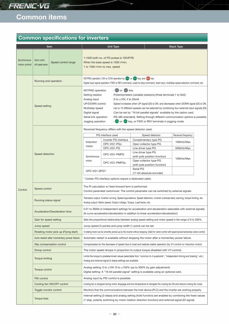
Common items
Received frequency differs with the speed detector used.
PG interface used Speed detector Received frequencyInverter PG interfaceOPC-VG1-PGoOPC-VG1-PG
OPC-VG1-PMPG
OPC-VG1-PMPGo
OPC-VG1-SPGT
Induction motor
Synchronous motor
Complimentary type PGOpen collector type PGLine driver type PGLine driver type PG(with pole position function)Open collector type PG(with pole position function)Serial PG(17-bit absolute encoder)
100kHz/Max
500kHz/Max
100kHz/Max
* Certain PG interface options require a dedicated cable.
30
Common specifications for inverters
Item Unit Type Stack Type
The PI calculation w/ feed forward term is performed.Control parameter switchover: The control parameter can be switched by external signals
Transistor output: Inverter running, Speed equivalence, Speed detection, inverter overload early warning, torque limiting, etc.Analog output: Motor speed, Output voltage, Torque, Load factor, etc.
Speed detection
Speed control
Running status signal
0.01 to 3600s (4 independent settings for acceleration and deceleration selectable with external signals)(S-curve acceleration/deceleration in addition to linear acceleration/deceleration)Acceleration/Deceleration time
Gain for speed setting Sets the proportional relationship between analog speed setting and motor speed in the range of 0 to 200%.
Jump speed Jump speed (3 points) and jump width (1 point) can be set.
Rotating motor pick up (Flying start) A rotating motor can be smoothly picked up by the inverter without stopping. (Valid for vector control with speed sensor/sensorless vector control)
Slip compensation control Compensates for the decrease of speed due to load and realizes stable operation (by V/f control w/ induction motor).
Droop control The motor speed droops in proportion to output torque (disabled with V/f control).
Cooling fan ON/OFF control Cooling fan is stopped during motor stoppage and low temperature to elongate the cooling fan life and reduce cooling fan noise.
Toggle monitor control Monitors that the communications between the host device (PLC) and the inverter are working properly.
Torque biasInternal setting (3 steps) and analog setting (hold function) are enabled by combining the fixed values(1 step, polarity switching by motor rotation direction function) and external signal (DI signal).
Torque controlAnalog setting: 0 to ±10V /0 to ±150% (up to 300% by gain adjustment)Digital setting: A "16-bit parallel signal" setting is available using an optional card.
PID control Analog input by PID control is possible.
Torque limitingLimits the torque to predetermined values (selectable from "common to 4 quadrants", "independent driving and braking", etc.)Analog and external signal (2 steps) settings are available.
Auto-restart after momentary power failure Automatic restart is available without stopping the motor after a momentary power failure.
1:1500 (with no. of PG pulses is 1024P/R)When the base speed is 1500 r/min,1 to 1500 r/min to max. speed
KEYPAD operation: CW or CCW operation by or key, and keyDigital input signal operation: FWD or REV command, coast-to-stop command, reset input, multistep speed selection command, etc.
KEYPAD operation : or keySetting resistor :Potentiometers (variable resistors) (three terminals:1 to 5kΩ)Analog input :0 to ±10V, 4 to 20mAUP/DOWN control :Speed increases when UP signal (DI) is ON, and decreases when DOWN signal (DI) is ON.Multistep speed :Up to 15 different speeds can be selected by combining four external input signals (DI).Digital signal :Can be set by "16-bit parallel signals" available by the option card.Serial link operation :RS-485 (standard). Setting through different communication options is possible.Jogging operation : or key, or FWD or REV terminals in jogging mode
Speed control range
Running and operation
Speed setting
Control
Vector controlwith speed sensor
Synchronousmotor control

Sta
ndar
dS
peci
ficat
ions
Com
mon
Spe
cific
atio
nsTe
rmin
alFu
ncti
ons
Pro
tect
ive
Func
tio
nsE
xter
nal
Dim
ensi
ons
Nam
es an
dFu
nctio
ns o
f Par
tsDe
dica
ted
Mot
orSp
ecifi
catio
nsEx
tern
al Di
mens
ions
of D
edica
ted M
otor
sGu
idelin
es fo
rSu
ppres
sing H
armon
icsW
iring
Dia
gram
Op
tio
ns
31
Multiple winding motor drive
Direct parallel connection system *1
Multi-winding motor control
Item
Display 7-segment LED, LCD with backlight
Language display Japanese, English, Chinese, Korean
Running/stopping
Setting mode
Alarm mode
Minor fault
• Detected speed value • Speed reference value • Output frequency • Torque current reference value• Torque reference value • Torque calculation value • Power consumption (motor output) • Output current• Output voltage • DC link circuit voltage • Magnetic-flux reference value • Magnetic-flux calculation value• Load shaft speed • PID reference value • PID feedback value • PID output value• Ai adjusted value (12) • Ai adjusted value (Ai1) • Ai adjusted value (Ai2) • Optional monitor 1 to 6• Presence of digital input/output signal • Motor temperature • Heat sink temperature• Load factor • Input power (*) • Integral power consumption (*) • Operation time• Motor accumulated operation time/no. of starts (for each motor), etc.
Names and data are displayed.
[L-AL] is displayed.Stores and displays the detailed cause that triggers the minor fault.
Alarm during running
The latest and last ten pieces of alarm codes and the latest and the last three pieces of alarm detailed data are stored.Stores and displays alarm date and time by the calendar and time display function [accuracy: ±27 sec/month (Ta=25°C)].Data stored period: 5 years or more (at ambient temperature 25°C)Battery: built-in as standard for 30kW or higher capacity models, available as option for 22kW or lower capacity models. (available as option: OPK-BP)
Display andsetting
Control
Keypad
Motor selection Motor can be selected from three types by using (F79) or by combining the external signals (DI signals).
Temperature detectionNTC thermistor (Fuji Electric product or equivalent item)PTC thermistor (Trip level set by parameter) (for motor overheat protection)
PG pulse outputOutputs the input pulse such as a motor PG signal by fixed or free frequency dividing.Open collector and complimentary (same voltage as PGP terminal) can be switched by setting the unit internal switch.
Pulse train synchronous operation Options: OPC-VG1-PG (PR) : for line driver type pulse command input OPC-VG1-PGo (PR) : for open collector type pulse command input
Speed setting is possible by combining the UP command, DOWN command, and zero clear command using the external signal (DI signal).UP/DOWN control
3 types of stopping functions: STOP 1, 2 and 3.Stopping function
Self-diagnosis for detection circuit of the pulse encoder input signal (PA, PB)PG detection circuit self diagnosis
Running efficiency of the unit can be improved by calculating the max. elevation speed achieved by the weight for a vertical transfer unit or other similar units.Load adaptive control function
Suppresses load disturbances and vibrations.Observer
Rotary type and non-rotary type are available for tuning the motor constants.Off-line tuning
Used for tuning continuosly motor constants due to the motor temperature change.On-line tuning
Standard function: position control by servo lock and built-in transmitting circuit.Options: OPC-VG1-PG (PR) : for line driver type pulse command input OPC-VG1-PGo (PR) : for open collector type pulse command input
Position control
Option: Use of OPC-VG1-TBSIMaximum number of motor windings: 6Control specification: Only vector control with a speed sensor is available.
Option: Use of OPC-VG1-TBSIMaximum number of parallel modules: 3Carrier frequency is fixed at 2kHz. Restrictions apply to usage conditions such as the output cable length.
*1: Supported when the ROM version is H1/2 0020 or later, and the SER.No. product version is BC or later.Unit type: Can be used with FRN37VG1S-2 and FRN45VG1S-4 or higher.Stack type: Can be used with all capacities.
*) Not available for the stack type
Displays the following alarm codes;• dbH (Braking resistor overheat)(*) • dCF (DC fuse blown) • EF (Ground fault) • Er1 (Memory error) • Er2 (KEYPAD panel communication error) • Er3 (CPU error) • Er4 (Network error) • Er5 (RS-485 error) • Er6 (Operation procedure error) • Er7 (Output wiring error) • Er8 (A/D converter error) • Er9 (Speed disagreement) • Lin (Input phase loss)(*) • LU (Undervoltage) • nrb (NTC thermistor disconnection) • OC (Overcurrent) • OH1 (Overheating at heat sink) • OH2 (External alarm input) • OH3 (Inverter internal overheat) • OH4 (Motor overheat) • OL1 (Motor 1 overload) • OL2 (Motor 2 overload) • OL3 (Motor 3 overload) • OLU (Inverter unit overload) • OS (Overspeed) • OU (Overvoltage) • P9 (PG error) • PbF (Charging circuit error) (*) • dbA (Braking transistor abnormal) (*) • Err (Simulated fault) • OPL (Output phase loss detection) • dFA (DC fan lock) (*) • ErH (Hardware error) • EC (Encoder communications error) • ErA (UPAC error) *2 • Et1 (Encoder error) • Erb (Inter-inverter link communication error) • ECF (Functional safety circuit error) *1 • dO (Excessive position deviation) • LOC (Start stall) • ArE (E-SX error) • ArF (Toggle error) • SiF (Functional safety card error) *1 • SrF (Functional safety card error) *1
Unit Type Stack Type

Common items
Common specifications for inverters
32
*1) This function is available by the licensed FRENIC VG Loader (WPS-VG1-PCL).*2) C22.2 No.14 does not conform to the FRN160, 200, 220, 355, or 400VG1S-4J.*3) Certification of the stack type three-phase 690V series is currently pending.
Item
Main circuit capacitor life
Common functions
RS-485
USB
This is a input terminal to connect computers and programmable controllers via RS-485 communications.
USB connector (Mini B type) for connection with a computer.The following operations are enabled using the invertersupport loader: function code edit, transfer verification, and monitoring various states.
Auto life judgment function installed
• Displays and records accumulated time for control PCB capacitor life and cooling fan operation time• Displays and records inverter operation time.• Displays and records the maximum output current and the maximum internal temperature for the past one hour.
Maintenance
Communications
Historical trace (*1) Loads sampling data retained in the inverter to display with a graph.Sampling time: 50μs to 1s
Real-time trace (*1) Loads data from the inverter on a real-time basis to display with a graph.Sampling time: 1ms to 1s
Operation monitor (*1) I/O monitor, system monitor, alarm history monitor
Function code setting Function code setting states can be checked. Also edit, transfer, comparison, initialization are available.
Charge lamp Lit when the power is being supplied to the inverter body. Lit even with control power.
Trace back
Loads sampling data retained in the inverter at an alarm to display with a graph.Sampling time: 50μs to 1s (Note that sampling is enabled at 400μs or more except current.)Sampling data are stored into the memory using the battery power. Data stored period: 5 years or more (at ambient temperature 25°C)Battery: built-in as standard for 30kW or higher capacity models, available as option for 22kW or lower capacity models. (available as option: OPK-BP)
Display andsetting
Loader
Function code data
Communications
Set the VG7 function codes to activate each operation of the code (excluding the function codes for the VG7 third motor).Values read from the VG7 can be written to the FRENIC-VG without changing them by using the PC loader (except for some special items).
T-Link, SX bus, and CC-Link are fully compatible. The host PLC software can be used without any change (except for some special items).
Installation adaptor An adapter to fit the installation dimensions of earlier models is available as option.
Compatibility with earlier models
VG7
Stopping function
Usage environment Indoor use only. Free from corrosive and flammable gases, dusts, and oil mist (pollution degree 2 - IEC60664-1). No direct sunlight.
Ambient temperature
5 to 95% RH (No dew condensation allowed)
Altitude
Ambient humidity
Vibration
Storage humidity 5 to 95% RH (No dew condensation allowed)
Storage temperature
3000m or lessHowever, the output may be reduced at the altitude of 1001 to 3000m For use at the altitude of 2001 to 3000m, the insulation class of the control circuit is changed from "Enhanced insulation" to "Basic insulation".
• 200V 55kW or less, 400V 75kW or less 3mm: 2 to 9Hz or less, 9.8m/s2: 9 to 20Hz or less, 2m/s2: 20 to 55Hz or less, 1m/s2: 55 to 200Hz or less• 200V 75kW or more, 400V 90kW or more 3mm: 2 to 9Hz or less, 2m/s2: 9 to 55Hz or less, 1m/s2: 55 to 200Hz or less
0.3mm: 2 to 9Hz1m/s2 : 9 to 200Hz
-25 to +70°C (-10 to +30°C for long-term storage)
-10 to +50°C (-10 to +40°C: In case of 22 kW or lower installed side-by-side without clearance) -10 to +40°C
Safe Torque Off (STO)• Stops the inverter output transistor by hardware -and therefore stops the output torque of the motor- immediately by turning OFF digital input signals (EN1 terminal or EN2 terminal), which are externally controlled.
• US and Canada Safety Standard UL, cUL (UL508C, C22.2 No.14)(*2)• Machinery Directive IEC/EN ISO13849-1: PL-d IEC/EN60204-1: stop category 0 IEC/EN61800-5-2: SIL2 IEC/EN62061: SIL2• Low Voltage Directive EN61800-5-1: Over voltage category 3• EMC Directive IEC/EN 61800-3(Certification being approved), IEC/EN 61326-3-1 (Emission) EMC filter (Option) : Unit type (220kW or lower) : Category 2 Unit type (280kW or higher) : Category 3 Stack type : Category 3 (Immunity) 2nd Env.
Safety function
Conformance to standard(*3)Product standard
Installation environment
Standard function
Unit Type Stack Type
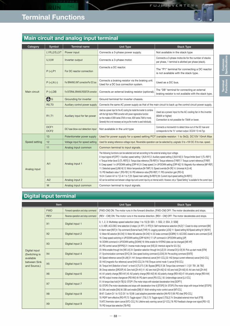
Terminal Functions
Sta
ndar
dS
peci
ficat
ions
Com
mon
Spe
cific
atio
nsTe
rmin
alFu
ncti
ons
Pro
tect
ive
Func
tio
nsE
xter
nal
Dim
ensi
ons
Nam
es an
dFu
nctio
ns o
f Par
tsDe
dica
ted
Mot
orSp
ecifi
catio
nsEx
tern
al Di
mens
ions
of D
edica
ted M
otor
sGu
idelin
es fo
rSu
ppres
sing H
armon
icsW
iring
Dia
gram
Op
tio
ns
33
Symbol Terminal nameCategory
L1/R,L2/S,L3/T Power input Connects a 3-phase power supply.
U,V,W Inverter output Connects a 3-phase motor.
Not available in the unit type
Connects a 3-phase motor.As for the number of stacks per phase, 1 terminal is allotted per phase (stack).
R0,T0 Auxiliary control power supply Connects the same AC power supply as that of the main circuit to back up the control circuit power supply.
13 Potentiometer power supply Used for power supply for a speed setting POT (variable resistor: 1 to 5kΩ). DC10V 10mA Max
11 Analog input common Common terminal to input signals.
Ai1 Analog input 1
Ai2 Analog input 2
M Analog input common Common terminal to input signals.
The following functions can be selected and set according to the external analog input voltage.0: Input signal off [OFF] 1: Auxiliary speed setting 1 [AUX-N1] 2: Auxiliary speed setting 2 [AUX-N2] 3: Torque limiter (level 1) [TL-REF1]4: Torque limiter (level 2) [TL-REF2] 5: Torque bias reference [TB-REF] 6: Torque reference [T-REF] 7: Torque current reference [IT-REF]8: Creep speed 1 in UP/DOWN setting [CRP-N1] 9: Creep speed 2 in UP/DOWN setting [CRP-N2] 10: Magnetic-flux reference [MF-REF]11: Detected speed [LINE-N] 12: Motor temperature [M-TMP] 13: Speed override [N-OR] 14: Universal Ai [U-AI]15: PID feedback value 1 [PID-FB1] 16: PID reference value [PID-REF] 17: PID correction gain [PID-G]18-24: Custom Ai1 to 7 [C-AI 1 to 7] 25: Speed main setting [N-REFV] 26: Current input speed setting [N-REFC]Ai2 can be switched over between voltage input and current input by an internal switch. However, only a "Speed Setting" is available for the current input.
12 Voltage input for speed setting Used for analog reference voltage input. Reversible operation can be selected by ±signals: 0 to +10V DC /0 to max. speed.
R1,T1
DCF1DCF2
Auxiliary input for fan power
DC fuse blow-out detection input
P (+),P1 For DC reactor connectionConnects a DC reactor.
Not available in the stack type
P (+),N (-) For BRAKING UNIT connection/For DC bus Connects a braking resistor via the braking unit. Used for a DC bus connection system.
Used as a DC bus.
P (+),DB For EXTERNAL BRAKING RESISTOR connection Connects an external braking resistor (optional).The "DB" terminal for connecting an external braking resistor is not available with the stack type.
The "P1" terminal for connecting a DC reactor is not available with the stack type.
Main circuit
Speed setting
Analog input
Main circuit and analog input terminal
Item
FWD Forward operation and stop command [FWD-CM] ON: The motor runs in the forward direction. [FWD-CM] OFF: The motor decelerates and stops.
REV Reverse operation and stop command
X1 Digital input 1
X2 Digital input 2
X3 Digital input 3
X4 Digital input 4
X5 Digital input 5
X6 Digital input 6
X7 Digital input 7
X8 Digital input 8
X9 Digital input 9
0, 1, 2, 3: Multistep speed selection (step 1 to 15) [0: SS1, 1: SS2, 2: SS4, 3: SS8] 4, 5: ASR, ACC/DEC time selection (4 steps ) [4: RT1, 5: RT2] 6: Self maintenance selection [HLD] 7: Coast-to-stop command [BX]8: Alarm reset [RST] 9: Trip command (External fault) [THR] 10: Jogging operation [JOG] 11: Speed setting N2/Speed setting N1 [N2/N1]12: Motor M2 selection [M-CH2] 13: Motor M3 selection [M-CH3] 14: DC brake command [DCBRK] 15: ACC/DEC cleared to zero command [CLR] 16: Creep speed switching in UP/DOWN setting [CRP-N2/N1] 17: UP command in UP/DOWN setting [UP] 18: DOWN command in UP/DOWN setting [DOWN] 19: Write enable for KYEPAD (data can be changed) [WE-KP] 20: PID control cancel [KP/PID] 21: Inverse mode change over [IVS] 22: Interlock signal for 52-2 [IL] 23: Write enable through link [WE-LK] 24: Operation selection through link [LE] 25: Universal DI [U-DI] 26: Pick up start mode [STM] 27: Synchronization command [SYC] 28: Zero speed locking command [LOCK] 29: Pre-exciting command [EXITE] 30: Speed reference cancel [N-LIM] 31: H41 (torque reference) cancel [H41-CCL] 32: H42 (torque current reference) cancel [H42-CCL] 33: H43 (magnetic-flux reference) cancel [H43-CCL] 34: F40 (Torque control mode 1) cancel [F40-CCL) 35: Torque limit (Selection of level 1 or level 2) [TL2/TL1] 36: Bypass [BPS] 37,38: Torque bias command 1 / 2 [37: TB1, 38: TB2] 39: Droop selection [DROOP] 40: Zero hold [ZH-AI1] 41: Ai2 zero hold [ZH-AI2] 42: Ai3 zero hold [ZH-AI3] 43: Ai4 zero hold [ZH-AI4]44: Ai1 polarity change [REV-AI1] 45: Ai2 polarity change [REV-AI2] 46: Ai3 polarity change [REV-AI3] 47: Ai4 polarity change [REV-AI4] 48: PID output inverse changeover [PID-INV] 49: PG alarm cancel [PG-CCL] 50: Undervoltage cancel [LU-CCL] 51: Ai torque bias hold [H-TB] 52: STOP1 (The motor stops with standard deceleration time) [SOPT1] 53: STOP2 (The motor decelerates and stops with deceleration time 4) [STOP2] 54: STOP3 (The motor stops with torque limiter) [STOP3]55: DIA card enable [DIA] 56: DIB card enable [DIB] 57: Multi-winding motor control cancel [MT-CCL] 58-67: Custom Di 1 to 10 [C-DI 1 to 10] 68: Load adaptive parameter selection [AN-P2/1] 69: PID clear [PID-CCL] 70: PIDFF term effective [PID-FF] 72: Toggle signal 1 [TGL1] 73: Toggle signal 2 [TGL2] 74: Simulated external minor fault [FTB] 75:NTC thermistor alarm cancel [NTC-CCL] 76: Lifetime early warning cancel [LF-CCL] 78: PID Feedback change-over signal [PID-1/2] 79: PID torque bias selection [TB-PID]
[REV - CM] ON: The motor runs in the reverse direction. [REV - CM] OFF: The motor decelerates and stops.
Digital input (Switching is available between Sink and Source.)
Digital input terminal
G Grounding for inverter Ground terminal for inverter chassis.
Unit Type Stack Type
Unit Type Stack Type
Used as a power input for the AC cooling fan inside the inverter to combine with the high factor PWM converter with power regenerative function (on the models of 200V series 37kW or more, 400V series 75kW or more).Generally this is not necessary as long as the inverter is used individually.
Used as a power input to the AC cooling fan in the inverter. (90kW or higher)Connection is not possible for 75kW or lower.
Connects a microswitch to detect blow-out of the DC fuse and corresponds to the "b" contact output. DC24V 12 mA Typ

Terminal Functions
Digital input terminal
34
Analog output
Transistoroutput
Relay output
Communications
Speed detection
Temperature
detection
Digital input(Safety function)
AO1 Analog output 1
Analog output 2
Analog output 3
AO2
AO3
Analog output common Common terminal to input signals.M
Transistor output 1Y1
Transistor output 2Y2
Transistor output 3Y3
Transistor output 4Y4
Transistor output common Common terminal to transistor output signals.CMY
Relay output Same functions as for Y1 to Y4 can be selected.Y5A,Y5C
Alarm relay output(for any fault)Outputs a potential-free contact signal (1C) when a protective function is activated to stop the inverter. Can select alarm for active or non active conditions.30A,30B,30C
RS-485 communicationsinput/output
Input/output terminals for RS-485 communications.Can connect up to 31 inverters through a multidrop (daisy chain) connection. Half-duplex method.DX+,DX-
USB port Front access, connector type: mini-B, USB 2.0 Full SpeedUSB port
Pulse generator 2-phase signal input Terminals for connecting 2-phase signal of pulse generator.PA,PB
Pulse generator power supply +15V DC pulse generator power supply (can be switched to +12V).PGP,PGM
Pulse generator output common Common terminals to FA and FB.CM
Pulse generator outputOutputs pulse encoder signal with a frequency that can be divided by configurable ratio (set by function code).Open collector and complimentary (same voltage as PGP terminal) can be switched.
FA,FB
NTC ThermistorPTC Thermistor connection
Motor temperature can be detected with the NTC and the PTC thermistors.The motor overheat protective level can be specified by the PTC thermistor function E32.
TH1,THC
Provides the monitor signal of 0 to ±10V DC for signals from the following:0: Detected speed (Speedometer, unipolar) [N-FB1+] 1: Detected Speed (Speedometer, bipolar)[F-FB1±]2: Speed setting 2 (Before acceleration/deceleration calculation) [N-REF2] 3: Speed setting 4 (ASR input) [N-REF4] 4: Detected speed [N-FB2±]5: Detected line speed [LINE-N±] 6: Torque current reference (Torque ammeter, bipolar) [IT-REF±]7: Torque current reference (Torque ammeter, unipolar) [IT-REF+] 8: Torque reference (Torque meter, bipolar) [T-REF±]9: Torque reference (Torque meter, unipolar) [T-REF+] 10: Motor current rms value [V-AC] 11: Motor voltage rms value [V-AC]12: Input power (motor output) [PWR] 13: DC link circuit voltage [V-DC] 14: +10V output test [P10] 15: -10V output test [N10]30: Universal AO [U-AO]31-37: Custom AO1 to 7 [C-AO1 to 7] 38: Input power [PWR-IN] 39: Magnetic pole position signal [SMP]40: PID output value [PID-OUT]
Outputs the selected signals from the following items:0: Inverter running [RUN] 1: Speed existence [N-EX] 2: Speed agreement [N-AG1] 3: Speed equivalence [N-AR]4, 5, 6: Detected speed 1, 2, 3 [4: N-DT1, 5: N-DT2, 6: N-DT3] 7: Stopping on undervoltage [LU] 8: Detected torque polarity (braking/driving) [B/D]9: Torque limiting [TL] 10, 11: Detected torque [10: T-DT1, 11: T-DT2] 12: KEYPAD operation mode [KP] 13: Inverter stopping [STOP]14: Operation ready completion [RDY] 15: Magnetic-flux detection signal [MF-DT] 16: Motor M2 selection status [16: SW-M2] 17: Motor M3 selection status [16: SW-M3] 18: Brake release signal [BRK] 19: Alarm indication1 [AL1] 20: Alarm indication 2 [AL2] 21: Alarm indication 3 [AL4] 22: Alarm indication 4 [AL8] 23: Fan operation signal [FAN] 24: Auto-resetting [TRY] 25: Universal DO [U-DO] 26: Heat sink overheat early warning [INV-OH] 27: Synchronization completion signal [SY-C] 28: Lifetime alarm [LIFE] 29: Under accelerating [U-ACC]30: Under decelerating [U-DEC] 31: Inverter overload early warning [INV-OL] 32: Motor temperature early warning [M-OH] 33: Motor overload early warning [M-OL] 34: DB overload early warning [DB-OL] 35: Link transmission error [LK-ERR] 36: Load adaptive control under limiting [ANL] 37: Load adaptive control under calculation [ANC] 38: Analog torque bias hold [TBH] 39-48: Custom DO 1 to 10 [C-DO 1 to 10] 50: Z-phase detection signal [Z-RDY] 51: Multiple-winding selected status [MTS] 52: Multiple-winding cancel response [MEC-AB] 53: Master selected status [MSS] 54: Parallel system self station alarm [AL-SF] 55: Communications error stopping [LES] 56: Alarm relay [ALM] 57: Minor fault [L-ALM] 58: Maintenance early warning [MNT] 59: Braking transistor error [DBAL] 60: DC fan lock signal [DCFL] 61: Speed agreement 2 [N-AG2] 62: Speed agreement 3 [N-AG3] 63: Axial fan operation stop signal [MFAN] 66: Droop selection response [DSAB] 67: Torque command/torque current command cancel response [TCL-C] 68: Torque limit mode cancel response [F40-AB] 71: 73 loading command [PRT-73] 72: Y-terminal test output ON [Y-ON] 73: Y-terminal test output OFF[Y-OFF] 75: Clock battery life80: EN terminal detection circuit error [DECF] *1 81: EN terminal OFF [ENOFF] *1 82: Safety function running [SF-RUN] *1 84: Performing STO diagnosis [SF-TST] *1
Analog output and transistor output terminal
Common terminal to digital input signals.
When the circuit is open between EN1-PS or EN2-PS terminals, the switching elements ofthe inverter main circuit is turned off and the output is shut off.
CM Digital input common
EN1,EN2 Safety functioninput terminalPS
PLC PLC signal power supplyConnects to PLC output signal power supply. It can also be used as a power supply for loads connected to the transistor outputs.+24V (22 to 27) max.100mA
Item
Item Unit type Stack type
Unit Type Stack Type
*1: Supported when the ROM version is H1/2 0020 or later, and the SER.No. product version is BC or later.*) The stack type is not supported.

Protective Functions
Protective function details
Sta
ndar
dS
peci
ficat
ions
Com
mon
Spe
cific
atio
nsTe
rmin
alFu
ncti
ons
Pro
tect
ive
Func
tio
nsE
xter
nal
Dim
ensi
ons
Nam
es an
dFu
nctio
ns o
f Par
tsDe
dica
ted
Mot
orSp
ecifi
catio
nsEx
tern
al Di
mens
ions
of D
edica
ted M
otor
sGu
idelin
es fo
rSu
ppres
sing H
armon
icsW
iring
Dia
gram
Op
tio
ns
35
ItemCategory Specifications Displays Relevant function codes
Braking transistor abnormal (*)
Braking resistor overheating (*)Estimates the braking resistor temperature and stops the inverter if the allowable value is exceeded.Setting E35 to 37 is required depending on the used resistor.
Memory error
KEYPAD panelcommunication error
Activated if a fault such as a "write error" occurs in the memory.(The number of times to write into the memory (nonvolatile memory) is limited(100,000 to 1,000,000 times). If data is written frequently and needlessly with the save all function, data changing and saving may be disabled, resulting in a memory error.)
CPU error Activated if a CPU error occurs.
Network error
RS-485 error
Operation procedure error
Output wiring error
A/D converter error
Speed disagreement
Invertercommunications error
Simulated fault
Stops the inverter if it detects a braking transistor abnormality.(Unit type: 200 V 55kW or lower, 400 V 160kW or lower)Be sure to shut off the inverter primary power when this alarm is detected.
Protective Functions
H103
E35 to E37
F02
o30,o31,H107E01 to E14E15 to E28
H32,H33H38,H107
H01
H01
E43,E44,E45H108,H149
H107
E01 to E14H108,H142
DC fuse blown
Encoder error
Excessive position deviation Activated if the positional deviation between the command and the detected values exceeds ten times function code o18 "Excessive deviation value" in synchronized operation.
o18
Safety circuit error *1Activated when the input for either EN1 or EN2 only turns off (mismatch judged if 50 ms exceeded). Protective function alarms can only be reset by rebooting the power.
Encoder communications error Activated if an encoder communications error is detected when using anABS encoder of 17-bit high resolution (option card OPC-VG1-SPGT).
Ground fault H103
Activated by a ground fault in the inverter output circuit. When ground-fault current is large, the overcurrent protective function may be activated. This function is provided to protect the inverter. Connect a separate earth-leakage protective relay or an earth-leakage circuit breaker if it is required to prevent accidents such as injury or fire.
This is displayed if the fuse for the main circuit DC blows because of a short-circuit in the IGBT circuit or other reason. This function is provided to prevent secondary accidents. Since inverter damage may have occurred, contact Fuji immediately.Unit type: Not less than 200V and 75kW, Not less than 400V, 90kWStack type: Full capacity
Activated if a communications error is detected between the inverter control circuit and the keypad when the start/stop command from the keypad is valid (function code F02=0).NOTE: A keypad communications error does not display or output an alarm when the inverter is operated by external signal input or the link function. The inverter continues operating.
Activated if a communication error occurs due to noise, etc. when the inverter is operated through T- Link, SX bus, E-SX bus, CC-Link, field bus, etc.
Activated if an RS-485 communications error occurs when function code H32 is set to 0 to 2 during inverter running via RS-485 communications and function code H38 is set between 0.1 and 60.0. This function is activated if the communications circuit is disconnected for longer than the time set in H38.
This function is activated at the following times:1) If multiple option cards are installed. 2) If multiple PG options are installed, and two function selection switches are set the same. 3) Activated if H01 auto tuning is started with any of the selected terminals for digital inputs
[BX], [STOP1], [STOP2], or [STP3] turned on. 4) Activated if the key on the keypad is not pressed for 20 seconds or more after
selecting H01 auto tuning.
Activated if an encoder error or failure is detected when using an ABSencoder of 17-bit high resolution (option card OPC-VG1-SPGT).
A simulated alarm state can be generated by keypad operation or thePC loader.
Activated if a transmission error occurs during communications between inverters using the high-speed serial communications terminal block (option).
Activated if the difference between the speed reference (speed setting) and the motor speed (detected speed, predicted speed) becomes excessive. The detection level and detection time can be set using function codes.
UPAC error *1 Activated when a UPAC option hardware fault occurs, a communication error occurs with the inverter control circuit, or the backup battery is consumed.
Activated if the wires are not connected in the inverter output circuit during auto tuning.
Activated if an error occurs in the A/D converter circuit.
*1: Supported when the ROM version is H1/2 0020 or later, and the SER.No. product version is BC or later.*) The stack type is not supported.

Protective Functions
Protective function details
36
Undervoltage F14
ItemCategory Specifications Displays Relevant function codes
NTC thermistor disconnection
External alarm input
Inverter internal overheat
Motor 1 overload
Motor 2 overload
Motor 3 overload
Motor overheat
Overheating of heat sink
Overcurrent
P30,A31,A131H106
F11,H106
A33,H106
A133,H106
H90
H108
H108
F80
H103,P01,A01,A101
H104
E01 to E14F106
E30,H106
Inverter overload
Output phase loss detection
Overspeed
PG error
Charge circuit error (*)
DC fan lock (*)
Overvoltage
Hardware error
E-SX bus tact out-of-sinc error
H107Toggle error
Stalled at start H108,H140,H141
P44,A64,A164
Activated if the torque current reference value is equal or higher than the level set in function code H140, and the detected speed value or estimated speed value is equal or lower than the speed set in function code F37 "stop speed", for the period of time set in function code H141. The detection level and detection time can be set using function codes.
Activated if the thermistor circuit is disconnected when the use of NTC thermistors for motors M1, 2, 3 is configured with the corresponding function codes P30, A31 and A131. Also activated in extreme low temperatures (approx. -30°C or lower).
Functional safety card error *1This is a protective function for the functional safety card.Refer to the functional safety card instruction manual for details.Functional Safety Card Instruction Manual INR-SI47-1541
The inverter stops when the external alarm signal (THR) becomes active. This alarm is activated via control terminals (assigned to THR) which are connected to alarm terminals of external devices such as a braking unit or a braking resistor (in case these devices trip).
Activated if the DC link circuit voltage exceeds the overvoltage level due to an increase of supply voltage or regenerative braking current from the motor. However, the inverter cannot be protected from excessive voltage (high voltage, for example) supplied by mistake.• Overvoltage detection level 200V series: 405V DC, 400V series: 820V DC, 690V series: 1230V DC
Activated if the detected temperature of the built-in NTC thermistor for motor temperature detection exceeds the data of function code E30 "Motor overheat protection."
Activated if the motor speed (detected speed value or estimated speed value) exceeds 120% (can be changed by H90) of the setting of function code "maximum speed" (F03, A06, A106).
Activated if the PA, PB or power supply circuits of the encoder interface are disconnected. However, a PG error is not activated when sensor-less control or V/f control is selected.
Activated if the bypass circuit of the DC link circuit (magnetic contactor for the charging circuit bypass) is not closed after power is supplied (200V 37kW or more, 400V 75kW or more).
Occurs if the PLC monitors the 2-bit signal of toggle signal 1 [TGL1] and toggle signal 2 [TGL2], and does not receive the specified change pattern after the time set in H144 elapses.
Occurs if the E-SX tact cycle and inverter control cycle are out of synch.
Activated if the DC fan stops (200V 45kW or more, 400V 75kW or more).
Stops the inverter by detecting LSI errors on the PCB.
Activated if the motor 1 current (inverter output current) exceeds the behavior level set by the function code F11.
Activated if the motor 2 current (inverter output current) exceeds the behavior level set by the function code A33.
Activated if the motor 3 current (inverter output current) exceeds the behavior level set by the function code A133.
Stops the inverter if an open phase is detected in the output wiring during operation.
Activated if the temperature of the heat sink that cools the rectifier diodes and the IGBTs increases due to cooling fan stoppage.
Activated if the output current exceeds the overload characteristic of the inverse time characteristic. The inverter is stopped according to the temperatures of the inverter cooling unit and the switching element that is calculated from the output current.
Cuts the output if motor current exceeds the inverter overcurrent specified value. This is also activated if the output current to the motor during synchronous motor control exceeds the value set for the overcurrent protection level (P44, A64, A164).
Activated if the ambient temperature of the control PC board increases due to poor ventilation of the inverter.
Activated if the DC link circuit voltage decreases to the undervoltagelevel due to a reduction in the supply voltage.The alarm is not output when the DC link circuit voltage decreases and function code F14 is set to "3 to 5".• Undervoltage detection level: 200V series: 180V DC, 400V series: 360V DC, 690V series: 470V DC
Protective Functions
Input open phase (*) E45The inverter is protected against damage due to input open phase. An open phase may not be detected if the connected load is small or a DC reactor is connected.
*1: Supported when the ROM version is H1/2 0020 or later, and the SER.No. product version is BC or later.*) The stack type is not supported.

Fuses and microswitches for stack type
Three-phase 400V series
Three-phase 690V series
Sta
ndar
dS
peci
ficat
ions
Com
mon
Spe
cific
atio
nsTe
rmin
alFu
ncti
ons
Pro
tect
ive
Func
tio
nsE
xter
nal
Dim
ensi
ons
Nam
es an
dFu
nctio
ns o
f Par
tsDe
dica
ted
Mot
orSp
ecifi
catio
nsEx
tern
al Di
mens
ions
of D
edica
ted M
otor
sGu
idelin
es fo
rSu
ppres
sing H
armon
icsW
iring
Dia
gram
Op
tio
ns
37
If an alarm or warning registered as a minor fault occurs, the minor fault indication [ ] is displayed on the keypad. For a minor fault, the minor fault output (Y terminal) is output. However, alarm relay output (30ABC) is not output and the inverter continues operating.Items to be set (Can be selected individually):
Motor overheat ( ), motor overload ( - ), NTC thermistor disconnection ( ), external alarm ( ), RS-485 communications ( ), option communications error ( ), inverter link error ( ), simulated fault ( ), DC fan lock detection ( ), speed disagreement ( ), E-SX error ( ), Stalled st Start ( ), motor overheat early warning, motor overload early warning, battery life, lifetime alarm, fin overheat early warning, overheating at heat sink, inverter overload early warning
The cause of each minor fault can be checked on the keypad.
Protects the inverter from surge voltage coming from the power supply using the surge absorber that is connected to the main circuit power supply terminal (unit type only: L1/R, L2/S, L3/T) and the control power supply terminal (Ro, To) circuit.
Monitors the inverter AC input power to judge if the AC input power (main power) is established or not. If not, whether the inverter is to be operated or not can be selected. (When the power is supplied via a PWM converter or DC bus connection, do not change the setting of function code H76 as no AC input exists.)
H76
H106 to H111
Protective Functions
Minor fault (warning)
Surge protection
Main power off detection (*)
NOTES: • All protective functions are reset automatically if the control power voltage decreases to where maintaining the operation of the inverter control circuit is impossible. • The latest and last ten alarm codes and the latest and the last three alarm detailed data are stored. • Stoppage due to a protective function can be reset from the RST key of the keypad or turning the circuit between the X terminal (assigned to RST) and the CM OFF and then ON. This action is invalid if the cause of an alarm is not found and resolved. If more than one alarm occurs at the same time, this action cannot be reset before resolving the causes of all alarms (the cause of an alarm that has not been cleared can be checked on the keypad). • "30A/B/C" do not operate if interrupted by a minor fault.*) Not available in the stack type
ItemCategory Specifications Displays Relevant function codes
* Fuses and microswitches are manufactured by Cooper Bussmann, but can also be ordered from Fuji.
Inverter type
MD specification LD specification Microswitch
Nominal appliedmotor capacity
[kW]
Nominal appliedmotor capacity
[kW]Fuse type Q'ty Fuse type TypeQ'ty Q'ty
Inverter type
MD specification LD specification Microswitch
Nominal appliedmotor capacity
[kW]
Nominal appliedmotor capacity
[kW]Fuse type Q'ty Fuse type TypeQ'ty Q'ty
FRN30SVG1S-4FRN37SVG1S-4FRN45SVG1S-4FRN55SVG1S-4FRN75SVG1S-4FRN90SVG1S-4FRN110SVG1S-4FRN132SVG1S-4FRN160SVG1S-4FRN200SVG1S-4FRN220SVG1S-4FRN250SVG1S-4FRN280SVG1S-4FRN315SVG1S-4FRN630BVG1S-4FRN710BVG1S-4FRN800BVG1S-4
303745557590110132160200220250280315630710800
170M3394-XA
170M3395-XA
170M3396-XA
170M3448-XA
170M4445-XA170M5446-XA
170M6546-XA
170M6547-XA170M6548-XA170M6500-XA
170M7532
170M7633
1
1
1
1
11
1
111111
3745557590
110132160200220250280315355710800
1000
170M3393-XA170M3394-XA170M3395-XA170M3396-XA170M3396-XA
170M3448-XA
170M4445-XA170M5446-XA
170M6546-XA
170M6547-XA170M6548-XA170M6500-XA
170M7633
170M7595
11111
1
11
1
111
1
1
1170H3027
FRN90SVG1S-69FRN110SVG1S-69FRN132SVG1S-69FRN160SVG1S-69FRN200SVG1S-69FRN250SVG1S-69FRN280SVG1S-69FRN315SVG1S-69FRN355SVG1S-69FRN400SVG1S-69FRN450SVG1S-69
90110132160200250280315355400450
170M3448-XA
170M4445-XA
170M6546-XA
170M6547-XA
2
2
2
2
110132160200220280315355400450
170M3448-XA
170M4445-XA
170M6546-XA
170M6547-XA
2
2
2
2
2170H3027
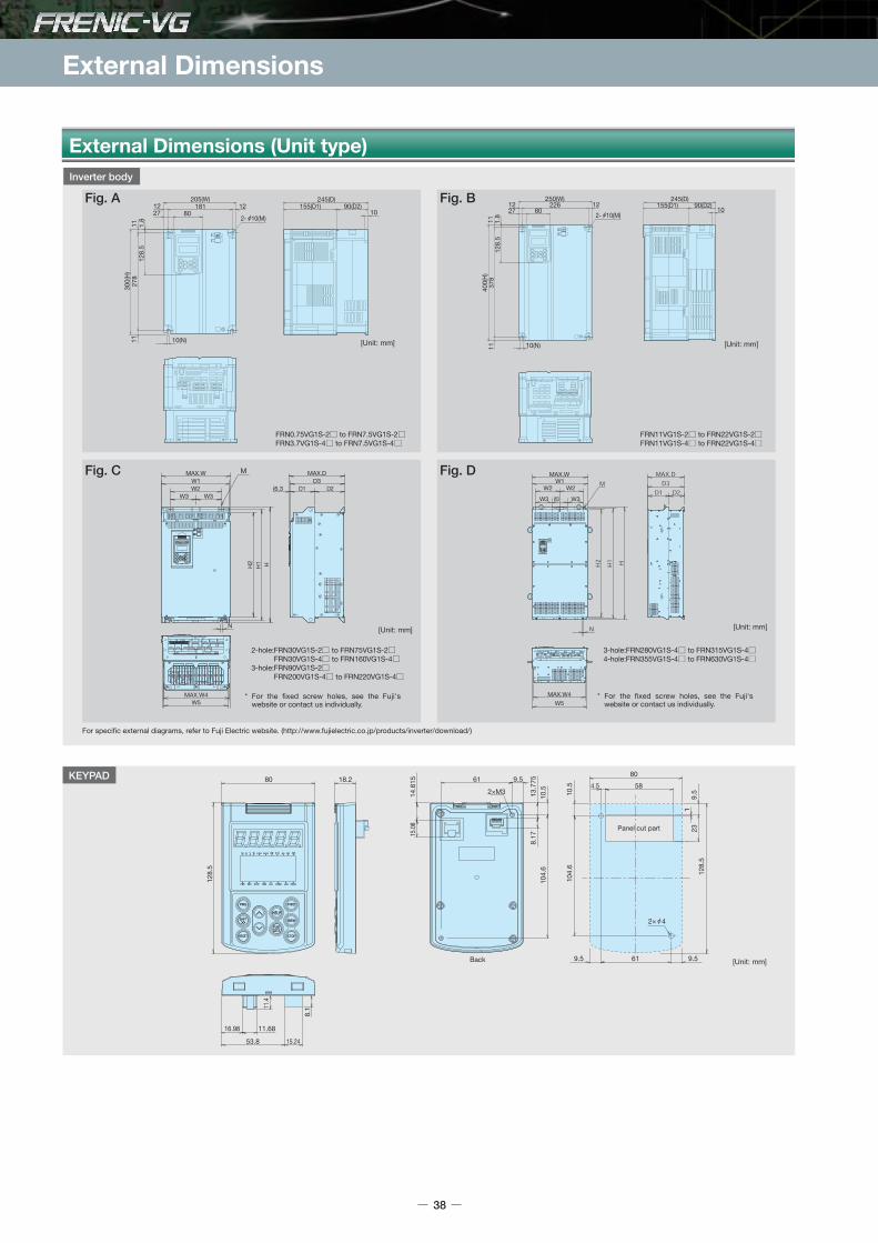
External Dimensions
External Dimensions (Unit type)
18.280
128.
5
16.98
8.1
11.68
53.8 15.24
11.4
61 9.5
2×M3 13.7
758.
1710
.510
4.6
Back
15.08
14.6
15
Panel cut part
10.5
128.
523
1
104.
6
4.5 5880
9.5 61
2× 4
9.5
9.5 [Unit: mm]
KEYPAD
2-hole:FRN30VG1S-2 to FRN75VG1S-2 FRN30VG1S-4 to FRN160VG1S-43-hole:FRN90VG1S-2 FRN200VG1S-4 to FRN220VG1S-4
3-hole:FRN280VG1S-4 to FRN315VG1S-44-hole:FRN355VG1S-4 to FRN630VG1S-4
* For the fixed screw holes, see the Fuji's website or contact us individually.
* For the fixed screw holes, see the Fuji's website or contact us individually.
FRN0.75VG1S-2 to FRN7.5VG1S-2FRN3.7VG1S-4 to FRN7.5VG1S-4
FRN11VG1S-2 to FRN22VG1S-2 FRN11VG1S-4 to FRN22VG1S-4
For specific external diagrams, refer to Fuji Electric website. (http://www.fujielectric.co.jp/products/inverter/download/)
W5
MAX.W
MAX.W4
MAX.DD3
D2D1W1W2
W3 W3
N
H2
H1 H
(6.3
W5MAX.W4
W1W2
W3 W3 W3
W2
MAX.WM
205(W)181 12
801227
10(N)
300(
H)27
812
8.5
1111 1.
8
245(D)90(D2)155(D1)
10
250(W)226
80271212
400(
H)37
811
1112
8.5
1.8
10(N)
245(D)90(D2)155(D1)
102- 10(M)
38
Fig. C Fig. D
[Unit: mm]
[Unit: mm]
[Unit: mm]
[Unit: mm]
Fig. A Fig. B
Inverter body
2- 10(M)

* Refer to the inverter type descriptions on P18 for details of the content indicated by .
AAAAAABBBBCCCCCCAAABBBBCCCCCCCCCCCDDDDDD
205
250
326.2
361.2
535.8686.4
205
250
326.2
361.2
536.4
686.4
886.4
1006
-
320
355
530680
-
320
355
530
680
880
1000
-
240
275
430-
-
240
275
430
-
290
-
-
290
-
290
-
260
300
-
310.2
345.2
506.4656.4
-
310.2
345.2
506.4
656.4
659
859.1
972
-
304
339
500.6650.6
-
304
339
500.6
650.6
653
853
966
300
400
550615
740
750880
300
400
550
615675
740
1000
1400
1550
-
530595
720
850
-
530
595655720
710
970
1370
1520
-
500565
690
688.7819.5
-
500
565625690
678.7
939.5
1330
1480
245
261.3
276.3
291.3366.3
245
261.3
276.3
321.3
366.3
445.5
446.3
505.9
155
115
145180
155
115
135
180
260
313.2
90
140
155
140180
90
140
155
180
186.8
-
255
270
285360
-
255
270
315
360
440
500
10
15
10
15
3-phase200V
3-phase400V
[Unit: mm]
Inverter type FigW W1 W2 W3 W4 W5 H H1 H2 D D1 D2 D3 M N
SeriesExternal dimensions
FRN0.75VG1S-2FRN1.5VG1S-2FRN2.2VG1S-2FRN3.7VG1S-2FRN5.5VG1S-2FRN7.5VG1S-2FRN11VG1S-2FRN15VG1S-2FRN18.5VG1S-2FRN22VG1S-2FRN30VG1S-2FRN37VG1S-2FRN45VG1S-2FRN55VG1S-2FRN75VG1S-2FRN90VG1S-2FRN3.7VG1S-4FRN5.5VG1S-4FRN7.5VG1S-4FRN11VG1S-4FRN15VG1S-4FRN18.5VG1S-4FRN22VG1S-4FRN30VG1S-4FRN37VG1S-4FRN45VG1S-4FRN55VG1S-4FRN75VG1S-4FRN90VG1S-4FRN110VG1S-4FRN132VG1S-4FRN160VG1S-4FRN200VG1S-4FRN220VG1S-4FRN280VG1S-4FRN315VG1S-4FRN355VG1S-4FRN400VG1S-4FRN500VG1S-4FRN630VG1S-4
2X 10
2X 153X 15
2X 10
2X 15
3X 15
4X 15
Sta
ndar
dS
peci
ficat
ions
Com
mon
Spe
cific
atio
nsTe
rmin
alFu
ncti
ons
Pro
tect
ive
Func
tio
nsE
xter
nal
Dim
ensi
ons
Nam
es an
dFu
nctio
ns o
f Par
tsDe
dica
ted
Mot
orSp
ecifi
catio
nsEx
tern
al Di
mens
ions
of D
edica
ted M
otor
sGu
idelin
es fo
rSu
ppres
sing H
armon
icsW
iring
Dia
gram
Op
tio
ns
39

External Dimensions
190
1515
4002.4
MAX 406.3(D)
740(
H)
711
605
2048
18
MAX 226.2(W)
1603013045
220
(REAR SIDE)
2xM5
2xM5
2x 10
190
1515
4003.2
MAX 406.3(D)
880(
H)
841
725
2048
18
3045
(REAR SIDE)
MAX 226.2(W)
160130
220
2xM5
2xM5
2x 10
1100
(H)
956
9463
5570
16030
MAX 226.2(W)220
2xM8
2xM8
1027
.891
.21.
6
550 11
2.3
MAX 567.3(D)
7075
191 17
17 455.3 38.5
9463
5570
2xM8
2xM8
16030
MAX 226.2(W)220
1400
(H)
1190
7075
191 17
17 455.3 38.5
2.3
1367
.2
2.3
91.2
550 11MAX 567.3(D)
1400
(H)
1190
9463
5570
16030
MAX 226.2(W)220
2xM8
2xM8
7075
191 17
17 455.3 38.5
1367
.291
.2
MAX 567.3(D)550 11
2.32.
3
1400
(H)
1190
9463
5570
16030
MAX 226.2(W)220
2xM8
2xM8
455.3
7075
191 17
38.517
1367
.291
.2
MAX 567.3(D)550 11
2.3
2.3
External Dimensions (Stack type)
Fig. A
[Unit: mm]
Fig. B
[Unit: mm]
Fig. C
[Unit: mm]
V-phase stack U-phase, W-phase stack
[Unit: mm]
Fig. D
Fig. E
[Unit: mm]
FRN30SVG1S-4 to FRN45SVG1S-4
FRN630BVG1S-4 to FRN800BVG1S-4 FRN630BVG1S-4 to FRN800BVG1S-4
[Unit: mm]
FRN132SVG1S-4 to FRN200SVG1S-4FRN132SVG1S-69 to FRN200SVG1S-69
FRN220SVG1S-4 to FRN315SVG1S-4FRN250SVG1S-69 to FRN450SVG1S-69
FRN55SVG1S-4 to FRN110SVG1S-4 FRN90SVG1S-69 to FRN110SVG1S-69
Fixingplate
Fixingplate
Fixingplate
Fixingplate
Fixingplate
Fixingplate
Fixingplate
Fixingplate
40

Inverter type FigW H D
Series
AAABBBBCCCDDDDEEEBBCCCDDDDDD
226.2
226.2
226.2
226.2
226.2
226.2
226.2
226.2
740
880
1100
1400
1400
880
1100
1400
406.3
406.3
567.3
567.3
567.3
406.3
567.3
567.3
3-phase400V
3-phase690V
[Unit: mm]External dimensions
FRN30SVG1S-4FRN37SVG1S-4FRN45SVG1S-4FRN55SVG1S-4FRN75SVG1S-4FRN90SVG1S-4FRN110SVG1S-4FRN132SVG1S-4FRN160SVG1S-4FRN200SVG1S-4FRN220SVG1S-4FRN250SVG1S-4FRN280SVG1S-4FRN315SVG1S-4FRN630BVG1S-4 (*1)FRN710BVG1S-4 (*1)FRN800BVG1S-4 (*1)FRN90SVG1S-69FRN110SVG1S-69FRN132SVG1S-69FRN160SVG1S-69FRN200SVG1S-69FRN250SVG1S-69FRN280SVG1S-69FRN315SVG1S-69FRN355SVG1S-69FRN400SVG1S-69FRN450SVG1S-69
*1) One inverter set consists of three stacks. The keypad comes with the V phase only.* Refer to the inverter type descriptions on P18 for details of the content indicated by .
External Dimensions / Names and Functions of the Keypad
Sta
ndar
dS
peci
ficat
ions
Com
mon
Spe
cific
atio
nsTe
rmin
alFu
ncti
ons
Pro
tect
ive
Func
tio
nsE
xter
nal
Dim
ensi
ons
Nam
es an
dFu
nctio
ns o
f Par
tsDe
dica
ted
Mot
orSp
ecifi
catio
nsEx
tern
al Di
mens
ions
of D
edica
ted M
otor
sGu
idelin
es fo
rSu
ppres
sing H
armon
icsW
iring
Dia
gram
Op
tio
ns
41
Names and Functions of the Keypad
Unit indicationDisplays the units for the information that appears on the LED monitor.
Program keySwitches the display to the menu screen or the initial screens for operation and alarm modes.
Shift key (column shift)Used to move the cursor horizontally in order to change data, and to jump to other function blocks (when pressed together with the UP/DOWN keys).
Reset keyProgram mode: Cancels the current input data and changes the screen.Trip mode:Releases a trip.
Up/Down keysOperation mode:Increases or decreases the speed. Program mode:Changes the function codes and specified data values.
LCD monitorDisplays different information ranging from operation status to function data.A real-time clock is installed as a standard feature.Operation guidance is scrolled along the bottom.
Operation keyStarts motor operation.
RUN LEDLit during operation by the FWD/REV signal or by operation commands via communications.
Function/Data select keyUsed to switch the displayed value on the LED monitor, input the speed setting and store function code data.
Stop keyStops motor operation.
HELP keyDisplays guidance screens including the key operation guidance for each LCD monitor display.
LED monitorOperation mode:Displays the setting frequency, output current, output voltage, motor speed, and line speed.Trip mode:Displays the cause of a trip.

Dedicated motor specifications (Induction motor with sensor)
42
3-phase 200V series standard specifications
Note 1) For motors applicable with 55 kW or more, the torque is accurate to ±5%.If you need more accuracy, contact Fuji.Note 2) If you need a motor other than the dedicated motor with 4 poles and base speed of 1500 r/min, contact Fuji Electric.Note 3) An optional holding break (outline drawing 112 or higher) can be manufactured. Please inquire separately for details on specifications and so on.
0.75 1.5 2.2 3.7 5.5 7.5 11 15 18.5 22 30 37 45 55 75 90
28 29 32 46 63 73 111 133 190 197 235 280 296 380 510 570
8095A
0.009
0.036
1500/3600
V10 or less
8097A
0.009
0.036
200 to 210V/50Hz,200 to 230/60Hz
Single phase, 4P
40/50
0.29/0.27 to 0.31
8107A
0.009
0.036
8115A
0.016
0.065
8133A
0.030
0.12
8135A
0.037
0.15
8165A
0.085
0.34
3-phase, 4P
90/120
0.49/0.44 to 0.48
8167A
0.11
0.47
8184A
0.21
0.83
150/210
0.75/0.77 to 0.8
8185A
0.23
0.92
8187A
0.34
1.34
1500/3000
8207A
0.41
1.65
8208A
0.47
1.87
9224A
0.53
2.12
1500/2400
V15 or less
200V/50Hz, 200,220V/60Hz
80/120
0.76/0.8.0.8
9254A
0.88
3.52
270/390
1.9/2.0,2.0
9256A
1.03
4.12
1500/2000
Dedicated motor rated output [kW]
Applicable motor type (MVK_)
Moment of inertia of rotor J [kg•m2]
Rotor GD [kgf•m2]
Base speed/Max. speed [r/min]
Vibration
Cooling fan*
Approx.weight [kg]
Voltage [V], Frequency [Hz]
Number of phases/poles
Input power [W]
Current [A]
Item Specifications
Insulation class/Number of poles
Terminal design
Mounting method
Degree of protection, Cooling method
Installation location
Ambient temperature, humidity
Color
Standard conformity
Standard built-in part
Class F/4P
Main terminal box (lug type): 3 or 6 main circuit terminals, NTC thermister terminals
= 2 pcs (MVK 8 series), 3 pcs (MVK 9 series, MVK 5 series, 1PC is a spare).
Auxiliary terminal box (terminal block): Pulse encoder (P6P, P6M,PA, PB, SS),
Cooling fan (FU, FV, FW)
Legs mounted (IMB3) NOTE: Contact FUJI for other methods.
IP44, Totally enclosed forced-ventilation system with cooling fan motor.
A cooling fan blows air over the motor toward the drive-end.
* Only the MVK8095A (0.75 kW) is a self-cooled type.
Indoor, altitude 1000m or less.
-10 to +40°C, 90%RH or less (no condensation)
Munsell N5
MVK8 series: JEM1466 or JEC-2137-2000,
MVK9 and MVK5 series: JEC-2137-2000
Pulse encoder (1024P/R, DC+5V, A ,B ,Z, U, V, W line driver output),
NTC thermistor 1 pc (2 pcs for 110kW or more), cooling fan
3.7 5.5 7.5 11 15 18.5 22 30 37 45 55 75 90 110 132 160 200 220
46 63 73 111 133 190 197 235 280 296 380 510 570 710 760 1270 1310 1630
8115A
0.016
0.065
1500/3600
V10 or less
200 to 210V/50Hz,200 to 230V/60Hz
Single phase, 4P
40/50
0.29/0.27 to 0.31
8133A
0.030
0.12
8135A
0.037
0.15
8165A
0.085
0.34
400 to 420V/50Hz,400 to 440V/60Hz
3-phase, 4P
90/120
0.27/0.24 to 0.25
8167A
0.11
0.47
8184A
0.21
0.83
150/210
0.38/0.39 to 0.4
8185A
0.23
0.92
8187A
0.34
1.34
1500/3000
8207A
0.41
1.65
8208A
0.47
1.87
9224A
0.53
2.12
1500/2400
V15 or less
400V/50Hz,400,440V/60Hz
80/
120
0.39/0.4,0.4
9254A
0.88
3.52
270/390
1.0/1.0,1.0
2200
4.6/4.3,4.1
3700
7.8/7.1,7.6
9256A
1.03
4.12
1500/2000
9284A
1.54
6.16
528KA
1.72
6.88
9286A
1.77
7.08
528LA
1.83
7.32
531FA
2.33
9.32
Dedicated motor rated output [kW]
Applicable motor type (MVK_)
Moment of inertia of rotor J [kg•m2]
Rotor GD [kgf•m2]
Base speed/Max. speed [r/min]
Vibration
Cooling fan
Approx.weight [kg]
Voltage [V], Frequency [Hz]
Number of phases/poles
Input power [W]
Current [A]
Item Specifications
250 280 315 355 400
1685 1745 2230 2310 2420
531GA
2.52
10.08
531HA
2.76
11.04
535GA
5.99
23.96
300
2230
535GA
5.99
23.96
535HA
6.53
26.12
535JA
7.18
28.72
Dedicated motor rated output [kW]
Applicable motor type (MVK_)
Moment of inertia of rotor J [kg•m2]
Rotor GD [kgf•m2]
Base speed/Max. speed [r/min]
Vibration
Cooling fan
Approx.weight [kg]
Voltage [V], Frequency [Hz]
Number of phases/poles
Input power [W]
Current [A]
Item Specifications
3-phase 400V series standard specifications
Common Specifications
Item Specifications
1500/2000
V15 or less
400V/50Hz,400,440V/60Hz
3-phase, 4P
3700
7.8/7.1,7.6
3-phase 400V series standard specifications
* Only the MVK8095A (0.75 kW) is a self-cooled type.
-
-
-
-
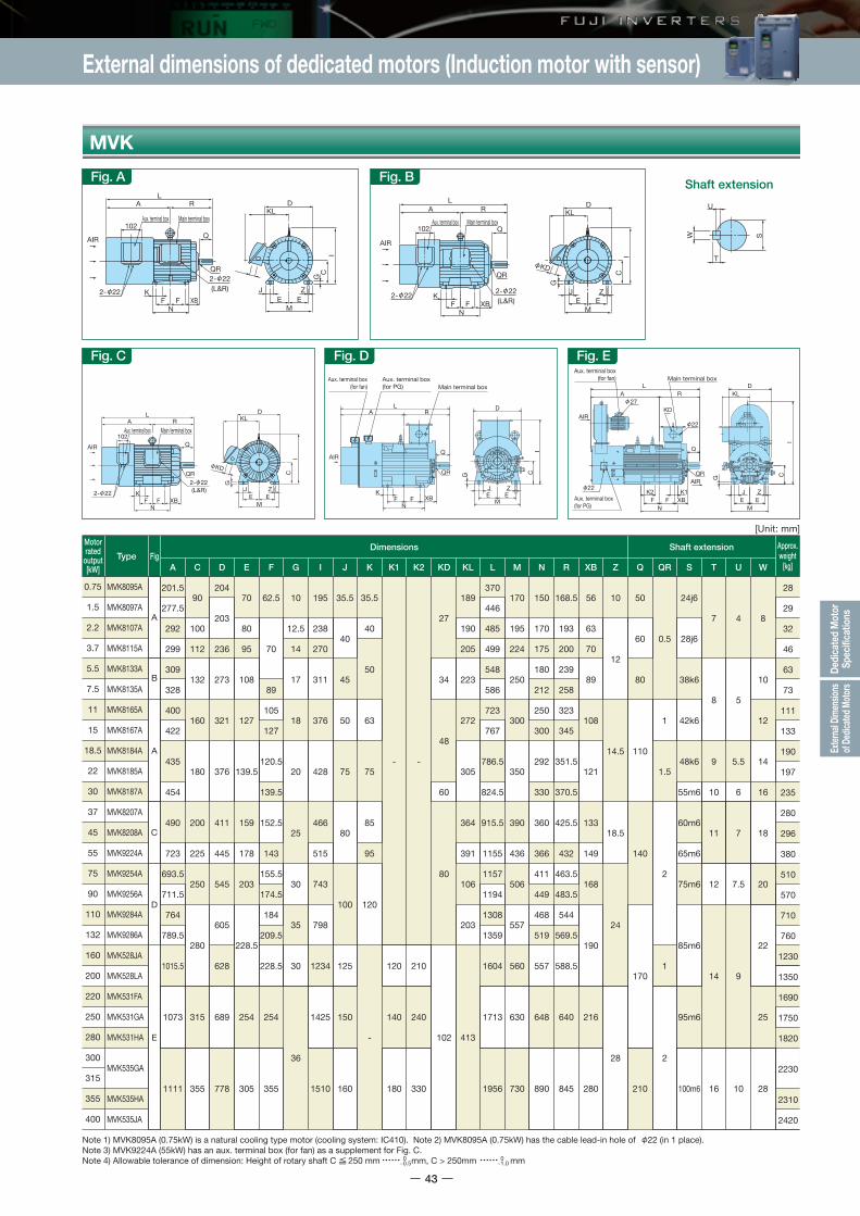
External dimensions of dedicated motors (Induction motor with sensor)
Sta
ndar
dS
peci
ficat
ions
Com
mon
Spe
cific
atio
nsTe
rmin
alFu
ncti
ons
Pro
tect
ive
Func
tio
nsE
xter
nal
Dim
ensi
ons
Nam
es an
dFu
nctio
ns o
f Par
tsDe
dica
ted
Mot
orSp
ecifi
catio
nsEx
tern
al Di
mens
ions
of D
edica
ted M
otor
sGu
idelin
es fo
rSu
ppres
sing H
armon
icsW
iring
Dia
gram
Op
tio
ns
43
MVK
Fig. A Fig. B
Fig. C Fig. D Fig. E
J ZE E
MXB
NFF
K
QR
Main terminal boxAux. terminal box Main terminal boxAux. terminal box
2- 22
Main terminal boxAux. terminal box
KD
2- 22(L&R)
DKL
LRA
Q
CG
I
102
AIR
J
MXB
N
K
QR
2- 222- 22(L&R)
DKL
LRA
Q
C
G
I
102
ZE EFF
AIR
QR
(L&R)
DKL
LRA
Q
C
G
I
102
J ZE E
MXB
NFF
K
AIR
T
U
SW
QR G
I
L
KF F XB
N
R
QAIR
C
JE
D
EM
Z
Aux. terminal box(for fan)
Aux. terminal box (for PG) Main terminal box
A
Shaft extension
Motorrated
output[kW]
0.75
1.5
2.2
3.7
5.5
7.5
11
15
18.5
22
30
37
45
55
75
90
110
132
160
200
220
250
280
300
315
355
400
Type
MVK8095A
MVK8097A
MVK8107A
MVK8115A
MVK8133A
MVK8135A
MVK8165A
MVK8167A
MVK8184A
MVK8185A
MVK8187A
MVK8207A
MVK8208A
MVK9224A
MVK9254A
MVK9256A
MVK9284A
MVK9286A
MVK528JA
MVK528LA
MVK531FA
MVK531GA
MVK531HA
MVK535GA
MVK535HA
MVK535JA
FigDimensions
28
29
32
46
63
73
111
133
190
197
235
280
296
380
510
570
710
760
1230
1350
1690
1750
1820
2230
2310
2420
A
201.5
277.5
292
299
309
328
400
422
435
454
490
723
693.5
711.5
764
789.5
1015.5
1073
1111
C
90
100
112
132
160
180
200
225
250
280
315
355
D
204
203
236
273
321
376
411
445
545
605
628
689
778
E
70
80
95
108
127
139.5
159
178
203
228.5
254
305
F
62.5
70
89
105
127
120.5
139.5
152.5
143
155.5
174.5
184
209.5
228.5
254
355
G
10
12.5
14
17
18
20
25
30
35
30
36
I
195
238
270
311
376
428
466
515
743
798
1234
1425
1510
J
35.5
40
45
50
75
80
100
125
150
160
K
35.5
40
50
63
75
85
95
120
-
K1
-
120
140
180
K2
-
210
240
330
KD
27
34
48
60
80
102
KL
189
190
205
223
272
305
364
391
106
203
413
L
370
446
485
499
548
586
723
767
786.5
824.5
915.5
1155
1157
1194
1308
1359
1604
1713
1956
M
170
195
224
250
300
350
390
436
506
557
560
630
730
N
150
170
175
180
212
250
300
292
330
360
366
411
449
468
519
557
648
890
R
168.5
193
200
239
258
323
345
351.5
370.5
425.5
432
463.5
483.5
544
569.5
588.5
640
845
XB
56
63
70
89
108
121
133
149
168
190
216
280
Z
10
12
14.5
18.5
24
28
Q
50
60
80
110
140
170
210
QR
0.5
1
1.5
2
1
2
T
7
8
9
10
11
12
14
16
U
4
5
5.5
6
7
7.5
9
10
W
8
10
12
14
16
18
20
22
25
28
S
24j6
28j6
38k6
42k6
48k6
55m6
60m6
65m6
75m6
85m6
95m6
100m6
Shaft extension Approx.weight
[kg]
A
A
B
C
E
D
Note 1) MVK8095A (0.75kW) is a natural cooling type motor (cooling system: IC410). Note 2) MVK8095A (0.75kW) has the cable lead-in hole of 22 (in 1 place).Note 3) MVK9224A (55kW) has an aux. terminal box (for fan) as a supplement for Fig. C.Note 4) Allowable tolerance of dimension: Height of rotary shaft C 250 mm mm, C > 250mm mm
[Unit: mm]
G
IC
DKL
J ZE E
M
AIRQR
AIR
22
22
27
K2 K1XBFF
N
LA R
Q
KD
Aux. terminal box(for fan)
Aux. terminal box (for PG)
Main terminal box
0−0.5
0−1.0
KD
2- 22
2- 22

Dedicated motor Specifications (Synchronous motor with sensor)
44
3-phase 200V series standard specification
5.5 7.5 11 15 18.5 22 30 37 45 55 75 90
2114A0.0180.072
2115A0.0210.084
2117A0.0270.107
2118A0.0360.143
2136A0.0650.259
2137A0.0700.281
2139A0.0900.360
1500/2000
V10 or less
2165A0.1530.610
2167A0.1910.763
2185A0.3501.401
2187A0.4671.868
2207A0.8053.220
20/20 29/29 42/42 57/57 71/70 82/81 113/108 144/144 165/165 200/200 270/270 316/316
51 55 69 78 100 106 127 170 192 247 325 420
Dedicated motor rated output [kW]
Dedicated motor type (GNF_)Moment of inertia of rotor [kg•m2]Rotor GD2 [kgf•m2]Base speed/Max. speed [r/min]Rated current [A]Vibration
Cooling fan
Approx.weight [kg]
Voltage [V], frequency [Hz]Number of phases/polesInput power [W]Current [A]
200 to 240,50/60 3-phase, 2P38 to 44/56 to 580.13 to 0.16/0.18 to 0.16
200 to 210/50,200 to 230/603-phase, 4P90/1200.49/0.44 to 0.48
54 to 58/70 to 780.18 to 0.18/0.22 to 0.21
150/2100.75/0.77 to 0.8
Item Specifications
3-phase 400V series standard specification
5.5 7.5 11 15 18.5 22 30 37 45 55 75 90
2114A0.0180.072
2115A0.0210.084
2117A0.0270.107
2118A0.0360.143
2136A0.0650.259
2137A0.0700.281
2139A0.0900.360
1500/2000
V10 or less
2165A0.1530.610
2167A0.1910.763
2185A0.3501.401
2187A0.4671.868
2207A0.8053.220
10/10 15/15 21/21 29/29 36/35 41/41 57/54 72/72 83/83 100/100 135/135 158/158
51 55 69 78 100 106 127 170 192 247 325 420
Dedicated motor rated output [kW]
Dedicated motor type (GNF_)Moment of inertia of rotor [kg•m2]Rotor GD2 [kgf•m2]Base speed/Max. speed [r/min]Rated current [A]Vibration
Cooling fan
Approx.weight [kg]
Voltage [V], frequency [Hz]Number of phases/polesInput power [W]Current [A]
200 to 240,50/60 3-phase, 2P38 to 44/56 to 580.13 to 0.16/0.18 to 0.16
400 to 420/50,400 to 440/60 3-phase, 4P90/1200.27/0.24 to 0.25
54 to 58/70 to 780.18 to 0.18/0.22 to 0.21
150/210 0.38/0.39 to 0.4
Item Specifications
Common Specifications3-phase 400V series standard specification
110 132 160 200 220 250 280
520 580 760 810 1000 1050 1100
2224B0.8823.53
2226B0.9943.98
2254B1.967.84
2256B2.228.88
228FB2.7911.2
228GB3.1212.5
228HB3.4713.9
198 232 273 340 390 445 475
Dedicated motor rated output [kW]
Dedicated motor type (GNF_)Moment of inertia of rotor [kg•m2]Rotor GD2 [kgf•m2]Base speed/Max. speed [r/min]Rated current [A]Vibration
Cooling fan
Approx.weight [kg]
Voltage [V]Number of phases/polesPower frequencyInput power [W]
Current [A]
Item Specifications
V10 or less380,400,415/400,415,440,4603-phase, 4P50/6080/1200.36,0.38,0.41/0.4,0.4,0.4,0.4
Insulation class/Number of poles
Terminal design
Rotation directionMounting methodOverload resistanceTime rating
Degree of protection, Cooling method
Installation locationAmbient temperature and humidityNoiseVibration resistancePainting colorStandard conformity
Standard built-in part
Item
Class F/6PMain terminal box (lug type): 3 or 6 main circuit terminals NTC thermister terminals = 2 pcs(1 pc is a spare), 110kW or more Auxiliary terminal box (terminal block): cooling fan (FU, FV, FW)Pulse encoder (connector type), cooling fan (FU, FV, FW)CCW direction when viewed from operatorLegs mounted (IMB3) (NOTE): Contact FUJI for other methods.150% 1min (*1)S1IP44, Totally enclosed forced-ventilation system with cooling fan motor. A cooling fan blows air over the motor toward the drive-end.Indoor, altitude 1000m or less.-10 to +40°C, 90% RH or less (no condensation)5.5kW to 90kW:80 dB(A) or less at 1m,110kW to 300kW:90 dB (A) or less at 1m6.86m/s2 (0.7G)Munsell N1.2JEM 1487: 2005Pulse encoder (1024 P/R, DC + 5 V, A ,B ,Z, U, V, W line driver output), NTC thermistor 1 pc (2 pcs for 110 kW or more), cooling fan
Specifications
1500/2000
270/3900.95,0.95,1/1,1,1,1
*1) When using the HD Specification, 150% for 1 min due to motor restriction.

Plug :JW2DW15SL1Terminal :JN1-22-22F 10320-52A0-008
3M
10320-52A0-008 3M
MVVS 16PX0.3mm2
MVVS 16PX0.3mm2
White marking indication position
White marking indication position
Cable shield wire connected to connector No.15 at motor side only.
Cable shield wire connected to connector No.15 at motor side only.
Inverter side
Inverter side
Motor side
Motor side
Plug :JN2FW15SL1Terminal :JN1-22-22F Japan Aviation Electronics Industry, Limited
Japan Aviation Electronics Industry, Limited
External dimensions of dedicated motors (Synchronous motor with sensor)
Cablemodel
Cable length(L dimension)
Motor side plug typeStraight plug Right angle plug
5m
15m
30m
50m
CB-VG1-PMPG-05S
CB-VG1-PMPG-15S
CB-VG1-PMPG-30S
CB-VG1-PMPG-50S
<Straight plug>
<Right angle plug>
CB-VG1-PMPG-05A
CB-VG1-PMPG-15A
CB-VG1-PMPG-30A
CB-VG1-PMPG-50A
Sta
ndar
dS
peci
ficat
ions
Com
mon
Spe
cific
atio
nsTe
rmin
alFu
ncti
ons
Pro
tect
ive
Func
tio
nsE
xter
nal
Dim
ensi
ons
Nam
es an
dFu
nctio
ns o
f Par
tsDe
dica
ted
Mot
orSp
ecifi
catio
nsEx
tern
al Di
mens
ions
of D
edica
ted M
otor
sGu
idelin
es fo
rSu
ppres
sing H
armon
icsW
iring
Dia
gram
Op
tio
ns
45
GNF2
51556978100106127170192247325420520580760810
100010501100
5.57.51115
18.522303745557590110132160200220250280
112Mh
112Jh
132Lh
132Hh160Lg160Jg180Lg180Jg200Jg225Kg225Hg
250Hg
280Jf
335.5335.5380.5380.5386386
424.5470.5501510576
618.5711761829829881881881
112112112112132132132160160180180200225225250250280280280
235235235235272272272319319375375410446446508505570570570
95959595108108108
139.5139.5159159178203203
228.5228.5254254254
7070100100101.5101.5140127
157.5139.5177.5200200250280280280280280
14141818202020202025252528283232353535
270270270270311311311376376428428549628628763763878878878
40405555454545757580100100100100100100120120120
50505050505050757585100100120120120120120120120
34344848484860808080808080808080102102102
200200235235247247247320320356356107142142203203303303303
555.5555.5698.5698.5705.5705.5782.5845.5906.5910.51061.51126.51249134914691469152115211521
224224228228250250250350350390420450506506557557628628628
175175238238238238313300370330450479526626677677680680680
220220318318
319.5319.5358375
405.5400.5485.5508538588640640640640640
7070108108108108108108108121168168168168190190190190190
1212
14.514.514.514.514.518.518.518.5242424242424282828
8080110110110110110140140140140140170170170170170170170
0.50.511
1.51.51.5222221111111
38k638k642k642k648k648k655m660m660m665m675m675m685m685m695m695m695m695m695m6
88889910111111121214141414141414
5555
5.55.56777
7.57.59999999
10101212141416181818202022222525252525
M10X20M10X20M10X20M10X20M10X20M10X20M10X20M12X25M12X25M12X25M12X25M12X25M20×35M20×35M20×35M20×35M20×35M20×35M20×35
GNF2114AGNF2115AGNF2117AGNF2118AGNF2136AGNF2137AGNF2139AGNF2165AGNF2167AGNF2185AGNF2187AGNF2207AGNF2224BGNF2226BGNF2254BGNF2256BGNF228FBGNF228GBGNF228HB
A
C
D
E
F
B
[Unit: mm]
Note 1) The models of 110kW or higher are designed to be coupled directly to the load. Contact Fuji in case of coupled to belt.Note 2) Allowable tolerance of dimension: Height of rotary shaft C 250mm mm, C > 250mm mm
Approx.weight
[kg]Type
Dimensions
A C D E G I J K KD KL L M
Motorrated
output[kW]
FigFrame
no.Shaft extension
N R XB Z Q QR T U YWSF
0−0.5
0−1.0
22KD 22
22
22
2222
Shaft extension
IC
G
Z
DKL
KD KD
M
JEE
S
QR
222- 22 22
2- 22 2- 22
2- 22
(L&R)
Main terminal boxAux. terminal box
Encoder connector
AIR
LA R
Q
NXBFF
K
CI
G Z
M
JEE
DKL
Encoder connector
Aux. terminal box Main terminal box
S
QR
(L&R)
AIR Q
LRA
NXBFF
K
C
G
E
DKL
I
ZJ
ME
※
AIR
(L&R)
Encoder connector
Aux. terminal box Main terminal box
N
S
QR
XBFFK
Q
LA R
※
Aux. terminal boxEncoder connector Main terminal box
AIR
S
RL
A
Q
QR
KXBF F
N
C
(L&R)KL
I
ZJG
D
E EM
Fig. EFig. D Fig. F
Fig. BFig. A Fig. C
CI
ZJ
G
EEM
DKL
AIR
AIRK
F F XBN
QS
QR
LRA
Aux. terminal box (for fan) Main terminal boxKD
Encoder connector
CI
ZJ
G
EEM
DKL
AIR
AIRK
F F XBN
Q
S
QR
LRA
Aux. terminal box (for fan) Main terminal boxKD
Encoder connector
KD
Dedicated inverter connection cables Cable arrangement diagram

Wiring Diagram
Basic Wiring Diagram (unit type)
46
(Note1) Install a recommended molded-case circuit-breaker (MCCB) or an earth-leakage circuit-breaker (ELCB) with an overcurrent protection function in the primary circuit of the inverter to protect the wiring. At this time, ensure that the circuit breaker capacity is equivalent to or lower than the recommended capacity.
(Note2) Install a magnetic contactor (MC) for each inverter to separate the inverter from the power supply, apart from the MCCB or ELCB, when necessary. Connect a surge absorber in parallel when installing a coil such as the MC or solenoid near the inverter.
(Note3) Connect this terminal to the power supply to retain relay alarm signal when the protection function is activated, or to keep the Keypad on, even when the inverter main power supply is cut. The inverter can be operated without supplying power to this terminal.
(Note4) Normally this is not necessary to connect. Used when combining the unit such as high power factor PWM converter with power regenerative function. (RHC series) (200 V series: 37kW or higher, 400V Series: 75kW or higher)
(Note5) When connecting a DC reactor (DCR option), remove the jumper bar from across the inverter main circuit terminals [P1] and [P(+)]. DC reactor is provided as standard in case of VG1S- J (Japan) model for 55 kW LD specification and for 75 kW or higher. DC reactor (option) must be used for all capacities under the following conditions: the capacity of the power transfomer is 500 kVA or more; or is ten times or more than the inverter rated capacity; or a load with thyristors is connected to the same power supply system.
(Note6) A braking transistor is built in the inverters with 55kW or less (200V series) and160kW or less (400V series). It can be directly connected across P(+)-DB.
(Note7) When connecting a braking resistor to the inverter with a capacity of 75 kW or more (200V series), or 200 kW or more (400V series), be sure to use a braking unit (option). Connect the braking unit (option) across P(+) and N(-). The auxiliary terminals [1] and [2] have polarity. Connect them according to the diagram above.
(Note8) This is a terminal for grounding the motor. To suppress inverter noise, it is recommended to use this terminal for motor grounding.
(Note9) Use twisted or shielded cables for the control signals. The shield conductor normally should be grounded, however, if noise is significantly induced from external devices, it may be suppressed by connecting it to ([M], [11], [THC]) or
([CM], [PGM]). Set apart from the main circuit wiring as far as possible, and avoid installing it in the same conduit. It is recommended to separate the control signals from the main circuit wires more than 10cm. If crossed, arrange the control wires so that they become almost perpendicular to the main circuit wiring.
(Note10) The functions indicated on terminals [X1] to [X9] (digital inputs), terminals [Y1] to [Y4] (transistor outputs), and terminal [Y5A/C] (contact output) are those assigned from factory default.
(Note11) This is a switching connector of the main circuit (fan power).(Note12) This is a switch on the control PCB.(Note13) The motor of 7.5kW or less has a single-phase power supply fan. In that case connect terminals FU and
FV. 400 V series motor of 7.5 kW or less has a cooling fan with a supply voltage of 200V / 50 Hz and 200 to 230 V / 60 Hz (single-phase). 400 V series motor with 11 kW or more has a cooling fan with a supply voltage of 400 to 420 V / 50 Hz and 400 to 440 V / 60 Hz (three phase). When the power supply voltage is other than the above, use a transformer to supply the cooling fan.
(Note14) The ([M], [11], [THC]) and ([CM], [PGM]) terminals are insulated on the inverter.(Note15) Confirm that the auxiliary contact of thermal relay can trip the line circuit breaker (MCCB) or the
electromagnetic contactor (MC).(Note16) A short-circuit conductor is connected between the safety function terminals [EN1] [EN2] and [PS] as the
factory default. To use this safety function, remove the short-circuit conductor before connection.
MCCB or ELCB
Ground terminal
Charge lamp
Voltagedetection
Basedriver
Processing controller
Alarm relay output (for any fault)(30A, 30B, 30C)
Contact point output
Relay output[RDY] Operation ready completion
Transistor output 4[N-DT1] Speed detection 1
Transistor output 3[N-AR] Speed equivalent
Transistor output 2[N-AG1] Speed agreement 1
Transistor output 1[N-EX] Speed existence
Analog output 1[N-FB1±] Speed detection 1
Analog output 2[IT-REF±] Torque current command
Analog output 3[N-REF4] Speed setting 4
Transistor output common
Analog output common
Data send/receive(RS-485)
Open collector output
Complimentary output
Sig
nal i
nput
sec
tion
Sig
nal o
utpu
t sec
tion
Currentdetection
Speed magnetic-fluxcalculator
Speed/magnetic-flux
position detector
Voltagedetection
NTCThermistor
Voltage input(0 to ±10VDC)Current input
(4 to 20mADC)
Thermal relay
Braking resistor (option)
Power voltage switching connector"CN UX"
Fan power connector"CN R" / "CN W"
Inverter unitGroundterminal
FRENIC-VG
Braking resistor (option)
Braking unit BU(option)
Dedicated motor
DC REACTOR(option)
Control power AUX input
Fan power AUX input
Analog input
Digital input
Digital input common
Speed setting input
Analog input 1[OFF] Input signal off
Analog input 2[OFF] Input signal off
Digital input 1[SS1] Multistep speed selection
Digital input 2[SS2] Multistep speed selection
Digital input 3[SS4] Multistep speed selection
Digital input 4[SS8] Multistep speed selection
Digital input 5[RT1] ASR acceleration/deceleration
Digital input 6[RT2] ASR acceleration/deceleration
Digital input 7[BX] Coast-to-stop command
Digital input 8[RST] Error reset
Digital input 9[THR] External alarm
Forward operation and stopping command
Safety signal
Reverse operation and stopping command
(Note 1)
(Note 3)
(Note 4) (Note 9)
(Note 9)
(Note 9)
(Note 2)
(Note 13)(Note 15)
(Note 7)
(Note 13)
(Note 6)
(Note 8)
(Note 5)
(Note 11)
(Note 9)
(Note 9)
(Note 12)
(Note 12)
(Note 10)
Transistor output
Analog output
Keypad
USB connector
(Note 10)
(Note 12)
(Note 12)
(Note 12)
(Note 11)
Magnetic contactor (MC)
Power supply200V series200 to 220V
50/60Hz
400V series380V to 480V
50/60Hz
(Note 10)
(Note 9)
(Note 16)
Transformer

Basic Wiring Diagram (stack type)
Fdc
FdcFacFac
Fac
U1
73-173-2
73A73C
R1S1 R0
T0T1
V1W1
L4L5L6
R3T3
Sta
ndar
dS
peci
ficat
ions
Com
mon
Spe
cific
atio
nsTe
rmin
alFu
ncti
ons
Pro
tect
ive
Func
tio
nsE
xter
nal
Dim
ensi
ons
Nam
es an
dFu
nctio
ns o
f Par
tsDe
dica
ted
Mot
orSp
ecifi
catio
nsEx
tern
al Di
mens
ions
of D
edica
ted M
otor
sGu
idelin
es fo
rSu
ppres
sing H
armon
icsW
iring
Dia
gram
Op
tio
ns
47
(Note 1) Install a recommended molded-case circuit-breaker (MCCB) or an earth-leakage circuit-breaker (ELCB) with an overcurrent protection function in the primary circuit of the inverter to protect the wiring. At this time, ensure that the circuit breaker capacity is equivalent to or lower than the recommended capacity.
(Note 2) Provide an electromagnetic contactor (MC) recommended for each converter to shut off the converter from the power supply (in addition to the MCCB or ELCB). When the MC, solenoid, or other coil is installed near the converter, a surge absorber should be connected in parallel with it.
(Note 3) Connect this terminal to the power supply to retain relay alarm signal when the protection function is activated, or to keep the Keypad on, even when the inverter main power supply is cut. The inverter can be operated without supplying power to this terminal.
(Note 4) Connect this when the inverter capacity is 90kW or more.(Note 5) This is a terminal for grounding the motor. To suppress inverter noise, it is recommended to use this
terminal for motor grounding. (Note 6) Use twisted or shielded cables for the control signals. The shield conductor normally should be
grounded, however, if noise is significantly induced from external devices, it may be suppressed by connecting it to ([M], [11], [THC]) or ([CM], [PGM]). Set apart from the main circuit wiring as far as possible, and avoid installing it in the same conduit. It is recommended to separate the control signals from the main circuit wires more than 10cm. If crossed, arrange the control wires so that they become almost perpendicular to the main circuit wiring.
(Note 7) The functions indicated on terminals [X1] to [X9] (digital inputs), terminals [Y1] to [Y4] (transistor outputs), and terminal [Y5A/C] (contact output) are those assigned from factory default.
(Note 8) Changeover switch on the control printed circuit board
(Note 9) The power to the motor cooling fan is 400 to 420 V / 50 Hz or 400 to 440 / 60 Hz. If you use other voltages, it must be adjusted by using a transformer.
(Note 10) The ([M], [11], [THC]) and ([CM], [PGM]) terminals are insulated on the inverter.(Note 11) Confirm that auxiliary contact (manual recovery) of thermal relay can trip the line circuit breaker (MCCB)
or electromagnetic contactor (MC)(Note 12) A short-circuit conductor is connected between the safety function terminals [EN1] [EN2] and [PS] as the
factory default. To use this safety function, remove the short-circuit conductor before connection.(Note 13) Refer to the PWM converter and filter stack Instruction Manuals for details on PWM converter (RHC-D)
and filter stack (RHF-D) connection.(Note 14) Always use a fuse (Fdc). With the 400V Series, connect it to the P(+) side, and for the 690V series,
connect it to both the P(+) side and N(-) side.(Note 15) In order to isolate the circuit use an isolation transformer or B (NC) contacts of a magnetic contactor
whose coil is connected on power supply side.
Power supply400V Series
380V to 480V50 / 60 Hz
690V Series575V to 690V
50 / 60 Hz
MCCBor
ELCB
(Note 1)
(Note 2)
Filter stackRHF-D
PWM converterRHC-D (Note 13)(Note 13)
Sequencecircuit
TransformerThermal relay(Note 9)
(Note 11) Dedicated motor
Inverter stackFRENIC-VG Ground
terminal
(Note 5)
NTCthermistor(Note 6)
(Note 8)
(Note 8)
Basedriver
Speed/magnetic-flux
position detector
Speed magnetic-fluxcalculator
Currentdetection
Voltagedetection
Link circuitvoltage detection
Processingcontroller
Open collector outputComplimentary output
(Note 8)
Sign
al in
put s
ectio
n
Sign
al o
utpu
t sec
tion
Keypad
USB connector
(Note 8)
(Note 6)
Alarm relay output (for any fault)(30A, 30B, 30C)
Relay output[RDY] Operation ready completion
Contactpoint output
Transistoroutput
Transistor output 4[N-DT1] Speed detection 1
Transistor output 3[N-AR] Speed equivalent
Transistor output 2[N-AG1] Speed agreement 1
Transistor output 1[N-EX] Speed existence
Analog output 1[N-FB1±] Speed detection 1Analog output 2[IT-REF±] Torque current commandAnalog output 3[N-REF4]Speed setting 4Analog output common
Data send/receive(RS-485)
Analogoutput
Transistor output common
(Note 7)
(Note 7)Digital input
Digital input common
Forward operation andstopping command
Reverse operation andstopping command
Digital input 1[SS1] Multistep speed selection
Digital input 2[SS2] Multistep speed selection
Digital input 3[SS4] Multistep speed selection
Digital input 4[SS8] Multistep speed selection
Digital input 5[RT1] ASR acceleration/deceleration
Digital input 6[RT2] ASR acceleration/deceleration
Digital input 7[BX] Coast-to-stop command
Digital input 8[RST] Error reset
Digital input 9[THR] External alarm
(Note 6)
(Note 7)
Safety signal (Note 12)
(Note 8)
Analog input
Speed setting input
Chargelamp
Voltage input(0 to ± 10VDC)Current input
(4 to 20mADC)
Analog input 1[OFF] Input signal off
Analog input 2[OFF] Input signal off
(Note 6)
(Note 6)
(Note 8)(Note 6)
Fan power AUX input
Control power AUX input
(Note 4)
(Note 3)(Note 15)
(Note 14)

P(+) N(-) GG L1/R L2/S L3/T P1DB U V W
USB(miniB)
L2' L3'L1'
L2 L3L1
5 64
2 31
S TR G
T0R0
V WU
S TR
V WU
S TR
V WU
S TR
M3
3
For main power input and inverter output
Y2 Z2X2
Y1 Z1X1
Options
Option guides (Example of unit type)
Contactor *1
Contactor *2
48
Optional board
RJ-45for KEYPADconnection
Main circuit terminal block
Motor
Peripheral and structure options
Speed setting potentiometer
Tachometer
Control circuit terminal block
Technica
Technica
Power
MCCBor
ELCB
Arrester[CN5 ]
Suppresses induced lightning surges from the power source to protect entire equipmentconnected to the power source.[Dealt by Fuji Electric Technica]
PC loader for WindowsInverter support software(FRENIC-VG loader)This software is used to set the function codes of the inverter from a PC, to manage the data.("WPS-VG1-STR" is available as free download from our website.)
Extension cable for remote control[CB- S]
Cable used for remote control
* The items indicated with are dealt by Fuji Electric Technica.
This will become more effective in noise reduction if used together with the power filter for input circuit.
Surge voltage is generated if the cable between an inverter and a motor is several ten meters long. This product suppresses the surge voltage, preventing the motor from being damaged.(Can be used for motors of 75kW or lower.)
Absorbs surge voltage coming from L-load of magneticcontactor and solenoid valve to protect electronic devices from malfunctioning.
Power filter for output circuit[RNF S - ]
To be used together with a braking resistor to increase the inverter braking performance.
Braking unit[BU - C]
Increases braking capability for highly frequent stopping and large moment of inertia. When used together with a braking unit, connect this to the connection terminal of the braking unit.
Used for suppressing power source harmonics of inverters. It is also equipped with a power supply regenerative function to drastically increase braking capability and reduce energy consumption.* Use in combination with the RHC Series dedicated pressurization
reactor, resistor, and capacitor.
Power regenerative PMW converter, RHC series[RHC - C]
Surge supperession unit[SSU TA-NS]
Connected to the output of an inverter to:• Suppress fluctuations of motor terminal voltage.• Prevent damages to the motor insulation due to surge
voltage in 400V series inverter.*This filter is not limited by carrier frequency. Also, motor can be tuned while this option is installed.
Output circuit filter [OFL- -4A]
Surge killer
[S2-A-O (for magnetic contactor and solenoid valve)][S1-B-O (for mini control relay and timer)]
Surge absorber(Connect in parallel to the coil that is a generation source of surge.)
[FSL-323 (for 3-phase)][FSL-123 (for single -phase)]
Surge killer for L-load(Connect to the power circuit that is a generation source of surge.)
Technica
Technica
[For power supply normalization]1) Use if the power transformer capacity is 500kVA or more and exceeds
the inverter rated capacity by 10 times.2) Use if the inverter and a thyristor converter are connected to the same
transformer.*Check if the thyristor converter uses a commutation reactor. If not,an AC reactor must be connected to the power supply side.
3) Connect to prevent trips when trip occurs due to opening/closing of the phase-advancing capacitor for the power supply lines.
4) Use if the voltage unbalance exceeds 2%.[For improving the input power-factor and reducing harmonics] Used to reduce the input harmonic current (correcting power-factor)* For the drop effect, refer to the guideline appendix.
Battery for memory backup,storing trace back memory and calendar function[OPK-BP]30kW or more:standard equipment, 22kW: optional
Attachment for external coolingThe attachment to install the heat sink part of the inverter outside the panel. [PBVG7-7.5 (for up to 7.5kW)] [PB-F1-30 (for 11 to 22kW)]
Used to reduce radio noise. Suppressive effect to the frequency band is available by approximately 1MHz or more. This is appropriate as a simple measure against noise since it affects broad range in the frequency band.
Ferrite ring for reducing radio noise[ACL-40B, ACL-74B, F200160]
Dedicated filter to comply with the European EMCDirective (Emission). Install the filter while referringto the details in the installation manual.
This filter can be used for the same purpose as the EMC compliance filter, but is not an EMC compliance.
Used to reduce radio noise. This is effective for the AM radio frequency band.*Do not use it on the inverter output side.[Made by Nippon Chemi-con, dealt by Fuji Electric Technica]
Braking resistor [DB V- ]
EMC compliance filter[EFL- , FS , FN ]
TechnicaFilter capacitor for reducing radio noise [NFM M315KPD ]
TechnicaPower filter for input circuit[RNF C - ]
DC REACTOR [DCR - ]
*1 If not using an R0, T0 terminal, connect a connector at this location.
*2 If using an R0, T0 terminal, connect a connector at this location.

For main power input and inverter output
V WU
S TR
V WU
S TR
Option guides (Example of stack type)
GU V W
S TR G
M3
NP NP
Y2 Z2X2
Y1 Z1X1
USB(miniB)
V WU
S TR
3
Contactor *1
*1 If not using an R0, T0 terminal, connect a connector at this location.
*2 If using an R0, T0 terminal, connect a connector at this location.
*3
*3
T0R0
V WU
S TR R S T
T0R0
*3 If using a PWM converter, it is necessary to connect to the main power supply via the b contact on an electromagnetic contactor or via an isolation transformer.
For details, refer to the PWM converter Instruction Manual.
Contactor *2S
tand
ard
Spe
cific
atio
nsC
omm
onS
peci
ficat
ions
Term
inal
Func
tio
nsP
rote
ctiv
eFu
ncti
ons
Ext
erna
lD
imen
sio
nsNa
mes
and
Func
tions
of P
arts
Dedi
cate
d M
otor
Spec
ifica
tions
Exte
rnal
Dime
nsion
sof
Ded
icate
d Mot
ors
Guide
lines
for
Supp
ressin
g Harm
onics
Wiri
ng D
iagr
amO
pti
ons
49
Increases braking capability for highly frequent stopping and large moment of inertia. When used together with a braking unit, connect this to the connection terminal of the braking unit.
Braking resistor [DB V- ]
Optional board
RJ-45for KEYPADconnection
Motor
Speed setting potentiometer
Tachometer
Technica
Power
MCCBor
ELCB
Arrester[CN5 ]
Suppresses induced lightning surges from the power source to protect entire equipment connected to the power source.[Dealt by Fuji Electric Technica]
PC loader for WindowsInverter support software(FRENIC-VG loader)
Fuse
This software is used to set the function codes of the inverter from a PC, to manage the data.("WPS-VG1-STR" is available as free download from our website.)
Use a DC common fuse to prevent secondary damage like a broken stack inverter.*) It can be set on the N side
to detect blow-out fuse.
Extension cable for remote control[CB- S]Cable used for remote control
Connected to the output of an inverter to:- Suppress fluctuations of motor terminal voltage.- Prevent damages to the motor insulation due to surge voltage in 400V series inverter.
*This filter is not limited by carrier frequency. Also, motor can be tuned while this option is installed.
Battery for memory backup, storing trace back memory and calendar function[OPK-BP]Total capacity: Standard equipment
PWM converter(stack type)
ordiode rectifier(stack type)
Inverter(Stack type)
* The items indicated with are dealt by Fuji Electric Technica.Technica
Used to reduce radio noise. Suppressive effect to the frequency band is available by approximately 1MHz or more. This is appropriate as a simple measure against noise since it affects broad range in the frequency band.
Ferrite ring for reducing radio noise[ACL-40B, ACL-74B, F200160]
Contactor
Peripheral device forPWM converterFilter stack (RHF-D Series)
Output circuit filter [OFL- -4A]
To be used together with a braking resistor to increase the inverter braking performance.
Braking unit [BU - C]
Control circuit terminal block

Options
Optional card
Cable
Combination with built-in control option
Pattern 2Pattern 1 Pattern 3
32610161
Digital card (for 8 bit bus),Analog cardDigital card (for 8 bit bus)Field bus interface cardDigital card (for 16 bit bus)Safety cardControl circuit terminal
110101
100111
CategoryCN
ABCDEF
Port
101011
(1) Certain optional communication cards (OPC-VG1-TL and OPC-VG1-CCL, etc.) cannot be installed at the same time. An operation procedure error (Er6) will occur if these cards are installed at the same time.
(2) The usage of the OPC-VG1-DI, DIO, PG and PGo can be selected by setting the SW on the PCB. 2 cards of each of the types OPC-VG1-DI, DIO, PG and PGo can be installed, but if the SWs for selecting the usage mode are set to the same setting, an operation procedure error (Er6) is indicated.
(3) If using OPC-VG1-PG for motor speed detection, input from terminals (PA, PB) on the main unit control PCB is disabled.(4) The restrictions in the following table apply when installing the OPC-VG1-PG/PGo and OPC-VG1-PMPG/PMPGo.
(5) When you install OPC-VG1-PMPG, you should select terminals according to the control method. The terminals (PA, PB) on the control PC board of the main unit are enabled if vector control for induction motor with speed sensor is selected. The OPC-VG1-PMPG is enabled if vector control for synchronous motor with speed sensor is selected.
(6) OPC-VG1-SPGT can only be installed in the B port.
VG1-PG/PGo(SD)VG1-PMPG/PMPGoVG1-PG/PGo(LD)VG1-PG/PGo(PR)VG1-PG/PGo(PD)
VG1-PG/PGo(SD)VG1-PMPG/PMPGo VG1-PG/PGo(LD) VG1-PG/PGo(PR) VG1-PG/PGo(PD)
NGOKOKOK
NGNGNG
NGNG NG
Name Type Specifications RemarksCategory Switch with SW on the Pt board
Analog card
Digital card(8 bit)
Digital card(16 bit)
Fieldbusinterface cardSafety cardControl circuit terminalLoader
Package software
Synchronized interfaceF/V converterAio extension cardDi interface card
Dio extension card
PG interface expansion card
PG card for synchronous motor drive
T-Link interface cardCC-Link interface cardHigh-speed serial connections for UPACSX bus communication cardE-SX bus communication cardPROFINET-IRT
User Programmable Application CardPROFIBUS-DPDeviceNetFunctional safety cardTerminal block for high-speed serial communicationsInverter support loader
Tension control softwareDancer control softwarePosition control software
OPC-VG1-SN OPC-VG1-FV OPC-VG1-AIO OPC-VG1-DI
OPC-VG1-DIO
OPC-VG1-PG
OPC-VG1-PGo
OPC-VG1-SPGT OPC-VG1-PMPG OPC-VG1-PMPGoOPC-VG1-TL OPC-VG1-CCL OPC-VG1-SIUOPC-VG1-SX OPC-VG1-ESX OPC-VG1-PNET
OPC-VG1-UPAC OPC-VG1-PDP OPC-VG1-DEVOPC-VG1-SAFE OPC-VG1-TBSI WPS-VG1-STR WPS-VG1-PCL WPS-VG1-TEN WPS-VG1-DAN WPS-VG1-POS
Synchronizing interface circuits for dancer controlF/V converterExtension card of Ai 2 points + Ao 2 points16 bit Di of binary or 4-digit BCD + signFor setting the speed, torque and the torque current reference.Extension of Di (4bits) and Do (8bits) for function selection.Dio option card for direct landing control. Di × 16 bit + Do ×10 bitUPAC exclusive use+ 5V line driver type, voltage output PGs (A,B and Z-phase signals). Used for detecting motor speed, line speed, position reference and position detection.Open collector type voltage output PGs (A,B and Z-phase signals). Used for detecting motor speed, line speed, position reference and position detection.ABS encoder with 17 bit high resolution+5V line driver typeOpen collector typeT-Link interface cardCC-Link compliant card (Ver2.00)Use for UPAC communication systemSX bus communication cardE-SX bus communication cardPROFINET-IRT communication cardCompatible only with special inverter type VG1S- PNUser programming cardPROFIBUS-DP interface cardDeviceNet interface cardSafety standard compliant cardUsed for multiple-winding motor drive system, reactor connection systemFor Windows. (Free version)For Windows. (Paid version)For Windows. Supplied with inverter support loader (Paid) CD-ROM.
coming soon
coming soon
A, B + magnetic pole position(Max. 4bit)
OPC-VG1-DI (A)OPC-VG1-DI (B)OPC-VG1-DIO (A)
OPC-VG1-DIO (B)OPC-VG1-PG (SD)OPC-VG1-PG (LD)OPC-VG1-PG (PR)OPC-VG1-PG (PD)OPC-VG1-PGo (SD)OPC-VG1-PGo (LD)OPC-VG1-PGo (PR)OPC-VG1-PGo (PD)
D port(CN10)
F port(CN1)
B port(CN2)
A port(CN3)
E port(CN16)
C port(CN6)
Name Type SpecificationsCategory
Cable Extension cable for remote control
Encoder cable for GNF2
Dedicated UPAC cable
CB-5SCB-3SCB-1SCB-VG1-PMPG-05SCB-VG1-PMPG-15SCB-VG1-PMPG-30SCB-VG1-PMPG-50SCB-VG1-PMPG-05ACB-VG1-PMPG-15ACB-VG1-PMPG-30ACB-VG1-PMPG-50ACB-VG1-UPAC-3S
5m3m1m5m
15m30m50m5m
15m30m50m3m
Connection cable between an inverter and the KEYPAD panel
Straight plug
Angle plug
Connection cable for OPC-VG1-UPAC and computer
Length (m)
0.165
0.27750.41250.56250.8251.125
1.38751.652.252.7753.3754.1255.6256.75
0.27750.41250.56250.8251.125
1.38751.652.252.7753.3754.1255.6256.758.259.9
12.015.016.5
21.023.626.630.037.547.3
50

Braking resistor, braking unit (max. 150% torque, 10% ED)
* For the unit type (MD / LD) specification and stack type (LD) specification, refer to the User Manual. (Unit Type, Function Code Edition: 24A7- -0019, Stack Type Edition: 24A7- -0018)(Note 1) The duty cycle [%ED] are calculated as the 150% torque braking used for deceleration as described below.(Note 2) Two braking resistors are required for each of DB160V-41C, DB200V-41C, or DB220V-41C.(Note 3) When connecting three braking units or more in parallel, refer to the supplement document of the DB Unit instruction manual (notes in connecting multiple units) INR-HF51614.
[Selection procedure] All three conditions listed below must be satisfied simultaneously.1 "The maximum braking torque" does not exceed the value shown on the table.2 The energy discharged in the resistor for each braking (the area of the triangle shown in the above figure, area of rectangle in drawing on right) does not exceed "the discharging capability [kWs]" on the table.3 The average loss (energy discharged in the resistor divided by the braking interval) does not exceed "the average loss [kW]" shown on the table.
Braking timeT1
0 Time
150%
Repeat cycleT0
Braking timeT1
Brakingpower
Brakingpower
• Duty cycle %ED = ×100 [%]T1T0
Braking timeT12
0 Time
150%
Repeat cycleT0
Braking timeT12
Powersupplyvoltage
Nominalapplied motor
[kW] TypeOhmicvalue
Averageloss [kW]
Duty cycle[%ED]
Dischargingcapability [kWs]
Brakingtime [s]
Max. brakingtorque [%]
Unit type *(HD spec)
Inverter typeBraking unit
For unit type
Built-in unit
Braking resistor
Type Q'ty Q'ty
Continuous braking(150% torque conversion value)
Repetitive braking(100s or less cycle)
3-phase200V
3-phase400V
FRN0.75VG1S-2FRN1.5VG1S-2FRN2.2VG1S-2FRN3.7VG1S-2FRN5.5VG1S-2FRN7.5VG1S-2FRN11VG1S-2FRN15VG1S-2FRN18.5VG1S-2FRN22VG1S-2FRN30VG1S-2FRN37VG1S-2FRN45VG1S-2FRN55VG1S-2FRN75VG1S-2FRN90VG1S-2FRN3.7VG1S-4FRN5.5VG1S-4FRN7.5VG1S-4FRN11VG1S-4FRN15VG1S-4FRN18.5VG1S-4FRN22VG1S-4FRN30VG1S-4FRN37VG1S-4FRN45VG1S-4FRN55VG1S-4FRN75VG1S-4FRN90VG1S-4FRN110VG1S-4FRN132VG1S-4FRN160VG1S-4FRN200VG1S-4FRN220VG1S-4
−FRN280VG1S-4FRN315VG1S-4FRN355VG1S-4FRN400VG1S-4FRN500VG1S-4FRN630VG1S-4
− −
BU55-2CBU90-2C
BU220-4C
−
BU220-4C
BU220-4C
− −
DB2.2V-21B
DB3.7V-21BDB5.5V-21BDB7.5V-21BDB11V-21BDB15V-21BDB18.5V-21BDB22V-21BDB30V-21BDB37V-21BDB45V-21BDB55V-21CDB75V-21CDB90V-21CDB3.7V-41BDB5.5V-41BDB7.5V-41BDB11V-41BDB15V-41BDB18.5V-41BDB22V-41BDB30V-41BDB37V-41BDB45V-41BDB55V-41CDB75V-41CDB90V-41CDB110V-41CDB132V-41CDB160V-41CDB200V-41CDB220V-41C
DB160V-41CDB160V-41CDB132V-41CDB132V-41CDB132V-41CDB160V-41C
0.751.52.23.75.57.51115
18.5223037455575903.75.57.51115
18.522303745557590110132160200220250280315355400500630710800
22
2
−
2
3
4
−−
30Ω
24Ω16Ω12Ω8Ω6Ω4.5Ω4Ω2.5Ω2.25Ω2Ω1.6Ω2.4Ω/22Ω/296Ω64Ω48Ω32Ω24Ω18Ω16Ω10Ω9Ω8Ω6.5Ω4.7Ω3.9Ω3.2Ω2.6Ω2.2Ω3.5Ω/23.2Ω/2
2.2Ω/22.2Ω/22.6Ω/32.6Ω/32.6Ω/42.2Ω/4
1
1111111111111111111111111111111
223344
150%
150%
10s
10s
16.5
27.7541.2556.2582.5
112.5138.75
165225
277.5337.5412.5562.5675
27.7541.2556.2582.5
112.5138.75
165225
277.5337.5412.5562.5675825990120015001650
210023632663300037504725
10%ED
10%ED
0.1650.165
0.27750.27750.41250.41250.56250.56250.8250.8251.1251.125
1.38751.38751.651.652.252.252.7752.7753.3753.3754.1254.1255.6255.6256.756.75
0.27750.27750.41250.41250.56250.56250.8250.8251.1251.125
1.38751.38751.651.652.252.252.7752.7753.3753.3754.1254.1255.6255.6256.756.758.258.259.99.9
12.012.015.015.016.516.5
21.021.023.623.626.626.630.030.037.537.547.347.3
Built-in unit
Sta
ndar
dS
peci
ficat
ions
Com
mon
Spe
cific
atio
nsTe
rmin
alFu
ncti
ons
Pro
tect
ive
Func
tio
nsE
xter
nal
Dim
ensi
ons
Nam
es an
dFu
nctio
ns o
f Par
tsDe
dica
ted
Mot
orSp
ecifi
catio
nsEx
tern
al Di
mens
ions
of D
edica
ted M
otor
sGu
idelin
es fo
rSu
ppres
sing H
armon
icsW
iring
Dia
gram
Op
tio
ns
51
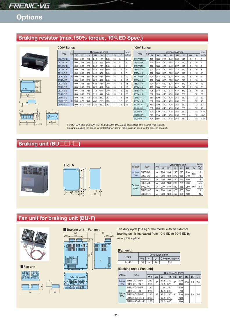
Options
Braking resistor (max.150% torque, 10%ED Spec.)
Braking unit (BU - )
Fan unit for braking unit (BU-F)
TypeDimensions [mm]
W W1 H H1 H2 D
DB2.2V-21BDB3.7V-21BDB5.5V-21BDB7.5V-21BDB11V-21BDB15V-21BDB18.5V-21BDB22V-21BDB30V-21BDB37V-21BDB45V-21BDB55V-21CDB75V-21CDB90V-21C
Fig
A
B
330400400400400400400400400405405450600700
298368368368368368368368368368368420570670
242280280480480660660660660750750440440440
210248248448448628628628628718718430430430
165203203377377557557557557647647250250250
140140140140140140140240240240340283283283
D1
1.61.61.61.61.61.61.61.61.61.61.6 − − −
CApprox.
weight [kg]
45567101013182226353343
8881010101010101010121212
Type
200V Series 400V SeriesDimensions [mm]
W W1 H H1 H2 D
DB3.7V-41BDB5.5V-41BDB7.5V-41BDB11V-41BDB15V-41BDB18.5V-41BDB22V-41BDB30V-41BDB37V-41BDB45V-41BDB55V-41CDB75V-41CDB90V-41CDB110V-41CDB132V-41C*DB160V-41C*DB200V-41C*DB220V-41C
420420420420420420420420425425550550650750750600725725
388388388388388388388388388388520520620720720570695695
280480480480660660660660750750440440440440440440440440
248448448448628628628628718718430430430430430430430430
203377377377557557557557647647250250250250250250250250
140140140140140140240240240340283283283283283283283283
D1
1.61.61.61.61.61.61.61.61.61.6 − − − − − − − −
CApprox.
weight [kg]
5778111114192126263041574337(×2)50(×2)51(×2)
81010101010101010101212121212121212
HH1
WW1
DD1
NP
H2
4- C
4- C
Fig.A
NP
H
H1
Fig.B
H2WW1
240
43D
Fig
A
B
* For DB160V-41C, DB200V-41C, and DB220V-41C, a pair of resistors of the same type is used. Be sure to secure the space for installation. A pair of resistors is shipped for the order of one unit.
The duty cycle [%ED] of the model with an externalbraking unit is increased from 10% ED to 30% ED byusing this option.
Fan unit
W1
H1
D1
DBUnitWARNING
Braking unit + Fan unit
H2
H3
H4
W3W4W2
D4 D3D2
Type
[Fan unit]Dimensions [mm]
BU-F 149W1
44H1
76D1
320(Fan power supply cable)
TypeDimensions [mm]
BU55-2C+BU-FBU90-2C+BU-FBU37-4C+BU-FBU55-4C+BU-FBU90-4C+BU-FBU132-4C+BU-FBU220-4C+BU-F
230250150230230250250
W2
135
135
W3
47.557.57.547.547.557.557.5
W4
240370280280280370450
H2
30
30
H3
270400310310310400480
H4
160
160
D2
1.2
1.2
D4D3
64
64
3-phase200V
3-phase400V
Voltage
[Braking unit + Fan unit]
Fig. A
H2
H1
H
W 6W1
15 D1.2
7.5
Voltage Type FigDimensions [mm] Approx.
weight[kg]W W1 H H1 H2 D
3-phase400V
3-phase200V
BU55-2CBU90-2CBU37-4CBU55-4CBU90-4CBU132-4CBU220-4C
AAAAAAA
230250150230230250250
130150100130130150150
240370280280280370450
225355265265265355435
210340250250250340420
160
160
694
5.55.5913
52

•FRN VG1S- J (Japanese) The DC Reactor (DCR) in thick-frame are provided as standard (supplied adding to the unit). The DC Reactor (DCR) is provided as standard for FRN55VG1S-2 and FRN55VG1S-4 of the LD specification, but not provided as standard for those units of HD specification.
•FRN VG1S- E (English), - C (Chinese) The DC reactor (DCR) is optional. (All capacities)*The DCR2/4- B type is also prepared for motors with 75kW or larger, which are applicable as standard. Contact us for ordering product separately.
DC Reactor (DCR - )
Fig. A Fig. B Fig. C
Fig. E Fig. FFig. D
3-phase200V
3-phase400V
FRN0.75VG1S-2FRN1.5VG1S-2FRN2.2VG1S-2FRN3.7VG1S-2FRN5.5VG1S-2FRN7.5VG1S-2FRN11VG1S-2FRN15VG1S-2FRN18.5VG1S-2FRN22VG1S-2FRN30VG1S-2
FRN37VG1S-2
FRN45VG1S-2
FRN55VG1S-2
FRN75VG1S-2FRN90VG1S-2 – FRN3.7VG1S-4FRN5.5VG1S-4FRN7.5VG1S-4FRN11VG1S-4FRN15VG1S-4FRN18.5VG1S-4FRN22VG1S-4FRN30VG1S-4
FRN37VG1S-4
FRN45VG1S-4
FRN55VG1S-4
FRN75VG1S-4FRN90VG1S-4FRN110VG1S-4FRN132VG1S-4FRN160VG1S-4FRN200VG1S-4FRN220VG1S-4 – FRN280VG1S-4FRN315VG1S-4FRN355VG1S-4FRN400VG1S-4 – FRN500VG1S-4FRN630VG1S-4 –
– – – – – – – – – – – – – – – – – – – – – – – – – – – – – – – – – – – – FRN90VG1S-4FRN110VG1S-4FRN132VG1S-4FRN160VG1S-4FRN200VG1S-4FRN220VG1S-4 – FRN280VG1S-4FRN315VG1S-4FRN355VG1S-4FRN400VG1S-4 – – –
– – – – – – – – – – –
FRN30VG1S-2
FRN37VG1S-2
FRN45VG1S-2
FRN55VG1S-2FRN75VG1S-2FRN90VG1S-2 – – – – – – – –
FRN30VG1S-4
FRN37VG1S-4
FRN45VG1S-4
FRN55VG1S-4FRN75VG1S-4FRN90VG1S-4FRN110VG1S-4FRN132VG1S-4FRN160VG1S-4FRN200VG1S-4 – FRN220VG1S-4 – FRN280VG1S-4FRN315VG1S-4FRN355VG1S-4FRN400VG1S-4FRN500VG1S-4FRN630VG1S-4
DCR2-0.75DCR2-1.5DCR2-2.2DCR2-3.7DCR2-5.5DCR2-7.5DCR2-11DCR2-15DCR2-18.5DCR2-22ADCR2-30BDCR2-37BDCR2-37CDCR2-45BDCR2-45CDCR2-55BDCR2-55CDCR2-75CDCR2-90CDCR2-110CDCR4-3.7DCR4-5.5DCR4-7.5DCR4-11DCR4-15DCR4-18.5DCR4-22ADCR4-30BDCR4-37BDCR4-37CDCR4-45BDCR4-45CDCR4-55BDCR4-55CDCR4-75CDCR4-90CDCR4-110CDCR4-132CDCR4-160CDCR4-200CDCR4-220CDCR4-250CDCR4-280CDCR4-315CDCR4-355CDCR4-400CDCR4-450CDCR4-500CDCR4-630CDCR4-710C
A
B
CBCDC
C
A
BBCBCBC
C
E
F
66668686
1111111111461461461521712101712101902552552553008686
111111146146146152171210171210171255255255300300350350350350350400400445440445285340
56567171959595
12412412490
11018511018516022522522526571719595
12412412490
110185110185110225225225265265310310310310310345345385385390145160
9090
10010010010010012012012015615110116610613196
10611611610010010010012012012015715010116510617096
106116116126131141146161161146156145150165203295
727280808080809696961161108112586907686969080808080969696115110811258613076869690100103113118133133118128117122137170255
2020102020232415252511511512512013510014014515518520202424152525100100105110120110120125140175180180185200210210200200213215220195225
M4(5.2×8)M4(5.2×8)M5(6×9)M5(6×9)
M6(7×11)M6(7×11)M6(7×11)M6(7×11)M6(7×11)M6(7×11)M6( 8)M6( 8)
M6(7×13)M6( 8)
M6(7×13)M6( 8)
M6(7×13)M6(7×13)M6(7×13)M8(10×18)M5(6×9)M5(6×9)
M6(7×11)M6(7×11)M6(7×11)M6(7×11)M6(7×11)M6( 8)M6( 8)
M6(7×13)M6( 8)
M6(7×13)M6( 8)
M6(7×13)M6(7×13)M6(7×13)M8(10×18)M8(10×18)
M10(12×22)M10(12×22)M10(12×22)M10(12×22)M10(12×22)M10(12×22)M10(12×22)M10(12×22)M10(12×22)M10(12×22)M12(14×20)M12( 15)
9494
110110130130137180180180130150125150125210145145145160110110130130168171171130150125150125150145145145155160190190190190190225225245245245480480
––––––––––
190200–
200–
250–––––––––––
190200–
210–
210–––––––––––––––––
M4M4M4M4M5M5M6M8M8M8
M10M10M10M10M12M12M12M12M12M12M4M4M5M5M5M6M6M8M8M8M8M8M8
M10M10M12M12M12M12M12M12M12M16M16
4×M124×M124×M124×M122×M124×M12
1.41.61.82.63.63.84.35.97.47.512147.4168.416111214172.62.64.24.35.97.27.213157.4188.4201113151922263033353740495262727595
0.751.52.23.75.57.51115
18.52230
37
45
55
75901103.75.57.51115
18.52230
37
45
55
7590110132160200220250280315355400450500630710
Voltage FigNominalapplied
motor [kW]
REACTORType
Approx.weight [kg]
Inverter Type Dimensions [mm]
HD Specification W W1 D D1 D2 G H H1 JMD Specification LD Specification
*For models with a standard motor of 75kW or more, it is included as a standard.
2-terminal(for screw J)
4-mounting holes(for screw G)
DD1
MAX.D2
WW1
H
2-terminal holes(for screw J)
D1
MAX. D2
D4-mounting holes(for screw G)
W1
H
W
W1
H
W 4-mountingholes
(for screw G)
D1
MAX.D2
D
40
2-terminal(for screw J)
H
W1W 4-mounting
holes(for screw G)
D1D
MAX. D2
2-terminal(for screw J)
MAX.D2
H
Terminal block(for screw J)
D1 D
W1W
4-mounting holes(for screw G)
2-terminal holes(for screw J)
D1
MAX.D2
D
H1
4-mounting holes(for screw G)
W1
H
W
H1
RemarksDC Reactor Type
The symbol at the end of the type codevaries depending on the capacity.Input power factor of DCR2/4- / A/ B: approx. 90 to 95%
This can be selected with the inverter of 37kW or more.Input power factor of the DCR2/4- C: about 86 to 90%
The DC reactor is mainly used for the unit type. With the stack type, the DC reactor is built into the diode converter and is used if necessary.* For details, refer to the Stack Type User Manual (24A7- -0018).
Sta
ndar
dS
peci
ficat
ions
Com
mon
Spe
cific
atio
nsTe
rmin
alFu
ncti
ons
Pro
tect
ive
Func
tio
nsE
xter
nal
Dim
ensi
ons
Nam
es an
dFu
nctio
ns o
f Par
tsDe
dica
ted
Mot
orSp
ecifi
catio
nsEx
tern
al Di
mens
ions
of D
edica
ted M
otor
sGu
idelin
es fo
rSu
ppres
sing H
armon
icsW
iring
Dia
gram
Op
tio
ns
53

Options
Note) It is not necessary to use the reactor unless a particularly stable power supply is required, i.e., DC bus connection operation (PN connection operation).Use the DC reactor (DCR) as a measure against harmonics.
ACR2-0.75AACR2-1.5AACR2-2.2AACR2-3.7AACR2-5.5AACR2-7.5AACR2-11AACR2-15AACR2-18.5AACR2-22AACR2-37ACR2-55ACR2-75ACR2-90ACR2-110ACR4-3.7AACR4-5.5AACR4-7.5AACR4-11AACR4-15AACR4-18.5AACR4-22AACR4-37ACR4-55ACR4-75ACR4-110ACR4-132ACR4-220ACR4-280ACR4-355ACR4-450ACR4-530ACR4-630
A
B
C
B
C
DE
120120120125125125125180180180190190250285280125125125180180180180190190190250250320380380460480510
404040404040406060606060
10019015040404060606060606060
100100120130130155155170
75757575909010085858590909012011075909085858585909090105115110110110230370370
100100100100115115125110110110120120120158138100115115110110110110120120126136146150150150290420420
2020202525106106106109109172200200190200106106106106106106106172200157202207240260260200−−
1151151151251259595115115115190190250210270959595115137137137190190190245250300300300490380390
M5(6×10)M5(6×10)M5(6×10)M5(6×10)M5(6×10)M5(6×10)M5(6×10)M6(7×11)M6(7×11)M6(7×11)M6(7×11)M6(7×11)M8(9×14)
M10(12×20)M8(10×20)M5(6×10)M5(6×10)M5(6×10)M6(7×11)M6(7×11)M6(7×11)M6(7×11)M6(7×11)M6(7×11)M6(7×10)
M8(9.5×18)M8(10×16)M10(12×20)M10(12×20)M10(12×20)M12(Φ15)
M12(15×25)M12(15×25)
M4M4M4M4M4M5M6M6M6M6M8M12M12M12M12M4M5M5M6M6M6M6M8M10M10M12M12M12M12M12
4×M124×M124×M12
1.92.02.02.43.13.13.74.85.15.111132526302.43.13.74.35.45.75.9121416243240525295
100110
3-phase200V
3-phase400V
AC Reactor (ACR - )
4-mounting holes(for screw G)
HW
W1
Fig. A
Fig. E
H
4-mounting holes(for screw G)
WW1
Fig. B
H
4-mounting holes(for screw G)
WW1
Fig. C
Fig. D
WW1
H
W
DD1154-mounting holes
(for screw G)W1
H
6-terminal(for screw J)
6-terminalholes(for screw J)
DD1
MAX.D2
DD1
MAX.D2
6-terminalholes(for screw J)
D4-mounting holes(for screw G)
MAX.D2
D1
6-terminal(for screw J)
Terminal block (for screw J)
DMAX.D2
D1
ReactorType Fig. No.
Dimensions [mm] Approx.weight [kg]W W1 D D1 D2 G H J
Voltage
54

ACL-40B
ACL-74B
F200160F200160PB
124124
1
421421
4
2.0, 3.5, 5.58, 1422, 38, 5.5×2, 8×2, 14×2, 22×28, 1422, 38, 60, 5.5×2, 8×2, 14×2, 22×2100, 150, 200, 250, 38×2, 60×2, 100×2150×2,200×2,250×2,325×2150×3,200×3,250×3,325×3250×4,325×4
NOTE) Use a 600V HIV insulation cable (Allowable temp. 75°C).
Zero-phase reactor for reducing radiated noise (ACL-40B, ACL-74B, F200160)
Applied wire size list
ACL-40B80
26 M
AX13
±0.3
2- 5.595 MAX
39.5
MIN
3578 M
AXNP
ACL-74B
181 MAX
131
MAX
74 M
IN
61
NP
1501226
MAX 8
13±0.3
4×R4
F200160(Without Mounting legs)
204±
1.0
156±
1.0
35±1
.0
F200160PB(With Mounting legs)
2-7 4-R3.5
220241 MAX
42 M
AX21
7 M
AX15
5 M
IN
20±2
Inverter terminals
Zero-phase reactorWires
Motor terminals WE
U V
Hand Lifter
Sta
ndar
dS
peci
ficat
ions
Com
mon
Spe
cific
atio
nsTe
rmin
alFu
ncti
ons
Pro
tect
ive
Func
tio
nsE
xter
nal
Dim
ensi
ons
Nam
es an
dFu
nctio
ns o
f Par
tsDe
dica
ted
Mot
orSp
ecifi
catio
nsEx
tern
al Di
mens
ions
of D
edica
ted M
otor
sGu
idelin
es fo
rSu
ppres
sing H
armon
icsW
iring
Dia
gram
Op
tio
ns
55
Ferrite ring types for reducing radio noise No. of turns Recommended wire size [mm2] Note)Q'ty
702
Wire ropeUpper pulley
Lower pulley
350
2406 6 120mmLeft movement
841
1254
250
180
477
603
1450
657
794
Lifti
ng ra
nge
0 to
800
mm
793
350
74.5
985mm
120mm120mmRight movement
72675 90° switchable type
100 moveable casters(with stopper)

Options
4- 13
Output circuit filter (OFL- 4A)[400V series]
UVWXYZ
D±2
A B
E±3
C
4-mounting holes(for screw K)
Grounding screw H
Terminal screw J NP
UVWXYZ
D±2
A B
E±3
C35
4-mounting holes(for screw K)
Grounding screw H
Terminal screw J NP
Fig.A
Fig. B
4- 10
430460
G
385
417
34
30
The reactor, capacitor and resistor forfilter OFL-30-4A or larger have to beinstalled separately.(Those items are not included in the mass indicated in the table below. They are shipped as a set by ordering the filter.)
Output terminal
550
620
NP
650450
30
500
Fig. F
Fig. G
D EB
MAX.F
MAX
.C10
0
4-mounting holes(for screw K)
6-terminal holes(for screw J)
6-terminal holes(for screw J)
Z1 Z2Y1 Y2X1 X2
A
4-mounting holes(for screw K)
6-terminal holes(for screw J)
D EB
MAX.F
MAX
.CZ1
Z2
Y1
Y2
X1
X2
A
EB
MAX.FM
AX.CZ1X1
Z2X2
DA
4-mounting holes(for screw K)
Y1
Y2
Fig. C
Fig. D
Fig. E
Filter dimensions (22kW or less) Filter dimensions (30kW or more):resistor/capacitorFilter dimensions (30kW or more):reactor
40
3-phase400V
FRN3.7VG1S-4 FRN5.5VG1S-4 FRN7.5VG1S-4 FRN11VG1S-4 FRN15VG1S-4
FRN18.5VG1S-4 FRN22VG1S-4 FRN30VG1S-4 FRN37VG1S-4 FRN45VG1S-4 FRN55VG1S-4 FRN75VG1S-4 FRN90VG1S-4 FRN110VG1S-4 FRN132VG1S-4 FRN160VG1S-4 FRN200VG1S-4 FRN220VG1S-4
–FRN280VG1S-4 FRN315VG1S-4 FRN355VG1S-4 FRN400VG1S-4
–FRN500VG1S-4 FRN630VG1S-4
–––
––––––
––––––
FRN90VG1S-4 FRN110VG1S-4 FRN132VG1S-4 FRN160VG1S-4 FRN200VG1S-4 FRN220VG1S-4
–FRN280VG1S-4 FRN315VG1S-4 FRN355VG1S-4 FRN400VG1S-4
–––––
––––––––
FRN30VG1S-4 FRN37VG1S-4 FRN45VG1S-4 FRN55VG1S-4 FRN75VG1S-4 FRN90VG1S-4 FRN110VG1S-4 FRN132VG1S-4 FRN160VG1S-4 FRN200VG1S-4
–FRN220VG1S-4
–FRN280VG1S-4 FRN315VG1S-4 FRN355VG1S-4 FRN400VG1S-4 FRN500VG1S-4 FRN630VG1S-4
––
OFL-3.7-4A
OFL-7.5-4A
OFL-15-4A
OFL-22-4A
OFL-30-4AOFL-37-4AOFL-45-4AOFL-55-4AOFL-75-4AOFL-90-4A
OFL-110-4AOFL-132-4AOFL-160-4AOFL-200-4AOFL-220-4A
OFL-280-4A
OFL-315-4AOFL-355-4AOFL-400-4AOFL-450-4AOFL-500-4AOFL-630-4A
–––
A
B
C/F
D/F
E/G
M4
M5
M6
M6
M5M5M6M6M8M8M8
M10M10M10M10
M10
M12M12M12M12M12M12
–
M4
M5
M6
M6
–––––––––––
–
––––––
–
–
–
–
–
160160160160233233233233233333333
333
––––––
–
–
–
–
–
9095
140150150155170170180190190
200
170175175195210245
–
115
160
145
170
140150155160170170190200200220250
250
230245240270280280
–
200
260
300
300
707570858585
100100100105115
115
150150150150150150
–
220
230
310
330
210220265275290290330340340350390
430
450480510470500560
–
225
290
275
300
175190195200210210230240240270300
300
275290295325335355
–
220
290
330
330
210220220260260260300300300320340
350
440440440440440480
–
M5
M6
M8
M8
M6M6M8M8
M10M10M10M10M10M12M12
M12
M12M12M12M12M12M12
–
14
22
35
45
1215172225283842486070
78
90100110125145170
–
3.75.57.51115
18.5223037455575901101321602002202502803153554004505006307108001000
Voltage FigNominalapplied
motor [kW]
FilterType
Approx.weight
[kg]
Inverter TypeUnit Type
Dimensions [mm]
HD SpecificationA B C D E F Grounding
screw HG Terminalscrew J
Mountingscrew KMD Specification LD Specification MD Specification
Stack TypeLD Specification
–––––––
FRN30SVG1S-4 FRN37SVG1S-4 FRN45SVG1S-4 FRN55SVG1S-4 FRN75SVG1S-4 FRN90SVG1S-4 FRN110SVG1S-4 FRN132SVG1S-4 FRN160SVG1S-4 FRN200SVG1S-4 FRN220SVG1S-4 FRN250SVG1S-4 FRN280SVG1S-4 FRN315SVG1S-4
––––
FRN630BVG1S-4 FRN710BVG1S-4 FRN800BVG1S-4
–
––––––––
FRN30SVG1S-4 FRN37SVG1S-4 FRN45SVG1S-4 FRN55SVG1S-4 FRN75SVG1S-4 FRN90SVG1S-4 FRN110SVG1S-4 FRN132SVG1S-4 FRN160SVG1S-4 FRN200SVG1S-4 FRN220SVG1S-4 FRN250SVG1S-4 FRN280SVG1S-4 FRN315SVG1S-4
––––
FRN630BVG1S-4 FRN710BVG1S-4 FRN800BVG1S-4
* Carrier frequency is not limited with OFL-*** -4A.
56

Power regenerative PWM converter (Unit and Stack Type)
Features
Applied Guideline for Suppressing HarmonicsPWM control reduces harmonics current significantly, due to sinusoidal wave at power supply side.According to "Guideline for Suppressing Harmonics by the Users Who Receive High Voltage or Special High Voltage" issued by the Ministry of Economy, Trade and Industry, the converter factor (Ki) can be set to "0" (meaning harmonics occurrence is 0) when combining with the inverter.
Possible to reduce power supply facility capacityIts power-factor control realizes the same phase current as the power-supply phase-voltage. The equipment, thus, can be operated with the power-factor of almost "1."This makes it possible to reduce the power transformer capacity and downsize the other devices, compared with those required without the converter.
Upgraded braking performanceRegenerated energy occurring at highly frequent accelerating and decelerating operation and elevating machine operation is entirely returned to power supply side. Thus, energy saving during regenerative operation is possible. As the current waveform is sinusoidal during regenerative operation, no troubles are caused to the power supply system.
Enhanced maintenance/protective functionsFailure can be easily analyzed with the trace back (option).The past 10 alarms can be displayed with the keypad LED display. This helps you analyze the alarm causes and take countermeasures.When momentary power failure occurs, the converter turns off the gates to enable continuous operation after recovery.The converter can issue warning signals like overload, heat sink overheating, or the end of service life prior to converter tripping.
Enhanced network support•The converter can be connected to MICREX-SX and CC-Link master devices (using option). The RS-485 interface is provided as standard. (Unit type)
Comparison of input current waveform
Allowable characteristics of the RHC unit
Rated continuous regeneration Rated regeneration for 1 min
100%150% MD (CT) spec.120% LD (VT) spec.*Stack type: 110%
0
10
20
30
40
50
60
70
80
90
100
110
120
130
140
150
160
170
180
170340
200400
250500
Power supply voltage (V)
Allowableregenerative
power
Max. allowable regenerative power (150%, 1 min.)
Continuous allowable regenerative power (100%, continuous)
(%)
<Without PWM converter> <With PWM converter>
Sta
ndar
dS
peci
ficat
ions
Com
mon
Spe
cific
atio
nsTe
rmin
alFu
ncti
ons
Pro
tect
ive
Func
tio
nsE
xter
nal
Dim
ensi
ons
Nam
es an
dFu
nctio
ns o
f Par
tsDe
dica
ted
Mot
orSp
ecifi
catio
nsEx
tern
al Di
mens
ions
of D
edica
ted M
otor
sPW
M co
nver
terRH
C-C,
RHC-
D se
ries
Wiri
ng D
iagr
amO
pti
ons
57

Options
Standard Specifications : MD (CT) specifications of medium overload, light overload LD (VT) specifications (Unit and Stack Type)
Unit type Three-phase 200V series
Unit type Three-phase 400V series
Stack type Three-phase 400V seriesItem Standard Specifications
132S132150
161
160182
196
160S160182
196
200227
244
200S200227
244
220247
267
220S220247
267
--
-
280S280314
341
315353
383
315S315353
383
355400
433
630B630705
762
710795
858
710B710795
858
800896
967
800B800896
967
10001120
1210
150% of rated current for 1 min.DC640 to 710V (Variable with input power supply voltage) (*3)
5kHz
110% of rated current for 1 min.DC640 to 710V (Variable with input power supply voltage) (*3)
5kHz3-phase, 380 to 440V 50Hz,380 to 460V 60Hz(*2)Voltage+10 to -10% Frequency ± 5%, Voltage unbalance: 2% or less (*4)
Type RHC -4D
(*2) The tap in the converter must be switched when the power supply voltage is 380 to 398V / 50Hz or 380 to 430V / 60Hz. The capacity must be reduced when the power supply voltage is less than 400V.(*3) The output voltage is 640 V DC, 686 V DC, and 710 V DC when the power supply voltage is 400 V, 440 V, and 460 V, respectively.(*4) Voltage unbalance [%] = (Max. voltage [V] - Min. voltage [V])/Three-phase average voltage [V] × 67(*5) The carrier frequency is automatically set to 2.5kHz when OPC-VG7-SIR is installed (transformerless connection).
58
Item Standard Specifications
7.57.58.8
9.5
1113
14
Power supplyvoltage
111113
14
1518
19
151518
19
18.522
24
18.518.522
24
2226
29
222226
29
3036
38
303036
38
3744
47
373744
47
4553
57
454553
57
5565
70
555565
70
7588
93
757588
93
90103
111
9090103
111
110126
136
CTSpecifications
VTSpecifications
150% of rated current for 1 min.DC320 to 355V (Variable with input power supply voltage) (*3)
Standard 15kHz Standard 10kHz
120% of rated current for 1 min.DC320 to 355V (Variable with input power supply voltage) (*3)
Standard 10kHz Standard 6kHz3-phase, 200 to 220V 50Hz,220 to 230V 50Hz(*1), 200 to 230V 60HzVoltage+10 to -15% Frequency ± 5%, Voltage unbalance: 2% or less (*4)
Type RHC -2CApplicable inverter capacity [kW]
Continuous capacity [kW]Overload ratingVoltage
Required power supply capacity [kVA]Carrier frequency(*5)Applicable inverter capacity [kW]
Continuous capacity [kW]Overload ratingVoltage
Required power supply capacity [kVA]Carrier frequency(*5)Number of phase/Voltage/FrequencyVoltage/Frequency variation
Output
Output
Power supplyvoltage
(*1) 220 to 230V / 50Hz model available on request.(*2) The tap in the converter must be switched when the power supply voltage is 380 to 398V / 50Hz or 380 to 430V / 60Hz. The capacity must be reduced when the power supply voltage is less than 400V.(*3) The output voltage is 320 / 640V DC, 343 / 686V DC, 355 / 710V DC when the power supply voltage is 200 / 400V, 220 / 440V and 230 / 460V, respectively.(*4) Voltage unbalance [%] = (Max. voltage [V] - Min. voltage [V])/Three-phase average voltage [V] × 67(*5) The carrier frequency is automatically set to 5kHz when OPC-VG7-SIR is installed (transformerless connection).
CTSpecifications
VTSpecifications
Applicable inverter capacity [kW]Continuous capacity [kW]Overload ratingVoltage
Required power supply capacity [kVA]Carrier frequency(*5)Applicable inverter capacity [kW]
Continuous capacity [kW]Overload ratingVoltage
Required power supply capacity [kVA]Carrier frequency(*5)Number of phase/Voltage/FrequencyVoltage/Frequency variation
Output
Output
7.57.58.8
9.5
1113
14
111113
14
1518
19
222226
29
3036
38
303036
38
3744
47
373744
47
4553
57
454553
57
5565
70
555565
70
7588
93
757588
93
90103
111
9090
103
111
110126
136
110110126
136
132150
161
132132150
161
160182
196
160160182
196
200227
244
200200227
244
220247
267
220220247
267
280314
341
280280314
341
315353
383
315315353
383
355400
433
355355400
433
400448
488
400400448
488
500560
610
500500560
610
--
-
630630705
762
--
-
151518
19
18.522
24
18.518.522
24
2226
29
Item Standard Specifications
Type RHC -4C
Power supplyvoltage
MDSpecifications
LDSpecifications
Applicable inverter capacity [kW]Continuous capacity [kW]Overload ratingVoltage
Required power supply capacity [kVA]Carrier frequency(*5)Applicable inverter capacity [kW]
Continuous capacity [kW]Overload ratingVoltage
Required power supply capacity [kVA]Carrier frequency(*5)Number of phase/Voltage/FrequencyVoltage/Frequency variation
Output
Output
150% of rated current for 1 min.DC640 to 710V (Variable with input power supply voltage) (*3)
Standard 15kHz
120% of rated current for 1 min.DC640 to 710V (Variable with input power supply voltage) (*3)
Standard 10kHz3-phase, 380 to 440V 50Hz,380 to 460V 60Hz(*2)Voltage+10 to -10% Frequency ± 5%, Voltage unbalance: 2% or less (*4)
Standard 10kHz Standard 6kHz
Standard 6kHz

Standard Specifications : MD (CT) specifications of medium overload, light overload LD (VT) specifications (Unit and Stack Type)
Sta
ndar
dS
peci
ficat
ions
Com
mon
Spe
cific
atio
nsTe
rmin
alFu
ncti
ons
Pro
tect
ive
Func
tio
nsE
xter
nal
Dim
ensi
ons
Nam
es an
dFu
nctio
ns o
f Par
tsDe
dica
ted
Mot
orSp
ecifi
catio
nsEx
tern
al Di
mens
ions
of D
edica
ted M
otor
sPW
M co
nver
terRH
C-C,
RHC-
D se
ries
Wiri
ng D
iagr
amO
pti
ons
59
Common specifications (Unit and Stack Type)
Control method
Running and operation
Running status signalMD(CT)/LD(VT) switchingCarrier frequencyInput power factorInput harmonics currentRestart mode after momentary power failurePower limit control
Alarm display (protective functions)
Alarm history
MonitorLoad factorDisplay languageCharge LED
AVR constant control with ACR minor loop.Rectification starts with power ON after connected. Boosting starts with the running signal (RUN-CM short-circuitor running command from communications). Then, preparation for operation is completed.Running, driving, regenerating, operation ready, alarm relay output (for any fault), etc.Selecting from MD (CT): Overload rating 150% (1 min.) and LD (VT): Overload rating 120% (1 min.)Fixed to high carrier frequencyAbove 0.99 (when 100% loading)According to the guideline for suppressing harmonics issued by the Ministry of Economy, Trade and Industry, the converter factor (Ki) can be set to 0.Stops the gates when the voltage level reaches undervoltage level if momentary power failure occurs, and the converter can automatically restart after the power recovers.Controls the power not to exceed the preset limit value.AC fuse blown, AC overvoltage, AC undervoltage, AC overcurrent, AC input current error, Input phase loss, Synchronous power supply frequency error, DC fuse blown, DC overvoltage, DC undervoltage, Charge circuit error, Heat sink overheat, External alarm, Converter overheat, Overload, Memory error, Keypad communication error, CPU error, Network device error, Operation procedure error, A/D converter error, Optical network error, IPM error (*1) Records and displays the last 10 alarms.The detailed information of the trip cause for the latest alarm is stored and displayed.Displays input power, input effective current, input effective voltage, DC intermediate current and power supply frequency.The load rate can be measured by using the keypad.Text can displayed in 3 languages: Japanese, English and Chinese.Lights when the main circuit capacitor is charged.
control
Displaysof
Keypad
ItemUnit Type Stack Type
Selecting from MD (CT): Overload rating 150% (1 min.) and LD (VT): Overload rating 110% (1 min.)5kHz (*2)
Lights when the main circuit capacitor is charged.Lights even when only input for control power.
(*1) Not available in the stack type(*2) The carrier frequency is automatically set to 2.5kHz when OPC-VG7-SIR is installed (transformerless connection).
Specifications

Options
[Terminal Functions] [Communications Specifications], [Function Settings], [Protective Functions], [Structure and environment]
Terminal Functions
Connects with a 3-phase power supply via the dedicated reactor.Connects with the inverter power supply input terminal P (+), N (-).Ground terminal for inverter chassis (housing).Connects with the same power circuit as that for the control power backup terminal and the main power circuit.Voltage detection terminals used for the internal converter control. These are connected with the power supply side of the dedicated reactor and filter.Terminals that connect with the circuit for detecting disconnection caused by blown AC fuse.The converter starts running when this command is ON between RUN and CM, and stops when OFF.In case of alarm stop, eliminate the cause and activate this input by closing the circuit between RST and CM. The protective function is disabled and the alarm state is released.0: External fault [THR], 1: Current limit cancel [LMT-CCL], 2: 73 answerback [73ANS], 3: Current limit switching [1-LIM], 4: Optional DI [OPY-DI]Common terminal to digital input signals.
–
Connects with the PLC output signal power supply. (Rated voltage: 24V (22 to 27V) DC) Outputs a signal when a protective function is activated to stop the converter.(Contact at 1C, Circuit between 30A and 30C comes ON when an alarm occurs) (Contact capacity: 250V AC, max 50mA.)0: Inverter running [RUN] 1: Operation ready output [RDY] 2: Power supply current limiting [IL] 3: Lifetime alarm [LIFE] 4: Cooling fin overload [PRE-OH] 5: Overload alarm [PRE-OL] 6: Driving [DRV] 7: Regenerating [REG] 8: Current limit alarm [CUR]9: Under restart [U-RES] 10: Power supply frequency synchronizing [SY-HZ] 11: Alarm indication [AL1]12: Alarm indication 2 [AL2] 13: Alarm indication 4 [AL4] 14: Optional DO [OPT-DO]* With OPC-VG7-DIO option, 8-point expanded functions become available (DI function is not available.)0: Input power [PWR] 1: Input current rms [I-AC] 2: Input voltage rms [V-AC] 3: DC link circuit voltage [V-DC] 4: Power supply frequency [FREQ] 5: + 10V output test [P10] - 10V output test [N10]* With OPC-VG7-AIO option, 2-point expanded functions become available (Ai function is not usable.)Common terminal to analog output signals.Control output for the input relay of the external charging resistor (73)
CategoryMain Power inputConverter outputGroundingAuxiliary control power supply inputSynchronous power supply input for voltage detectionControl monitor inputRUN commandAlarm reset commandGeneral-purpose transistor input
Digital input common
DC fuse blow-out detection input
PLC signal power Alarm relay output (for any fault)
General-purpose transistor output
Digital output commonRelay output
General-purpose analog output
Analog output commonCharging circuit relay output
Main circuit
Voltage detection
Input signal
Output signal
Unit Type Stack TypeL1/R, L2/S, L3/TP(+), N(–)E(G)R0, T0R1, S1, T1R2, T2RUNRSTX1
CM
DCF1,DCF2
PLC30A, 30B, 30C
Y1, Y2, Y3, Y11 to Y18
CMEY5A, Y5C
A01, A04, A05
M73A, 73C
When a DC fuse is connected to the converter output, a microswitch for detecting blow-out of the DC fuse is connected to this terminal. This terminal corresponds to the "b" contact output.DC 24V 12mA Typ
Terminal signal Terminal name Specifications
Communication specification
Enables to show running information and running status, and to monitor the function code (polling), and to control (selecting) RUN, RST, and X1.* No function code can be written.Communicates with the PC or PLC (Fuji protocol and modbus RTU are supported). OPC-VG7-TL option allows T-Link communication with the T-Link module in the MICREX-F or MICREX-SX.OPC-VG7-SX option allows connection with MICREX-SX via SX bus.OPC-VG7-CCL option allows connection with the CC-Link master device.OPC-VG7-SI / OPC-VG7-SIR option allows sharing the load by connecting in parallel 2 or more converters.
Item
CommunicationSpecification
Unit Type Stack TypeGeneral specifications for communication
RS-485T-Link (option card)SX bus (option card)CC-Link (option card)Optical communications (optional)
Specifications
Data protectionHigh-frequency filter selectionRestart mode after momentary power failure (operation selection)Current rating switchingLED monitor (Display selection)LCD monitor (Display selection)LCD monitor (Language selection)LCD monitor (Contrast adjusting)Carrier frequencyX1 function selectionY1,Y2,Y3,Y5,Y11 to 18 function selectionI/O function normally open/normally closedRHC overload early warning levelCooling fan ON-OFF controlOutput while limiting the current (hysteresis width)A01, A04, A05 function selectionA01, A04, A05 gain settingA01, A04, A05 bias settingA01 to 5 filter settingOperation methodPower supply current limit (drive/ control)Station addressCommunication error processing selectionTimer operation timeBaud rateData length selectionParity bit selectionStop bit selectionNo-response error detection timeResponse interval timeProtocol selectionTL transmission formatParallel systemNumber of slave stations in parallel systemAlarm data deletionPower supply current limit (drive 1/2)Power supply current limit (control 1/2)Current limit early warning (level/ timer)Power supply frequencyInput powerEffective input currentEffective input voltageRun commandRunning statusOutput terminals Y1 to Y18
F00F01F02F03F04F05F06F07F08E01E02 to 13
E14E15E16E17E18 to 20E21 to 23E24 to 26E27S01S02,03H01H02H03H04H05H06H07H08H09H10H11H12H13H14H15,16H17,18H19,20M09M10M11M12M13M14M15
Function Settings
Unit Type Stack TypeFunction code Name
ACFAOVALVAOCACELPVFrE
dCFdOV
dLV
PbF
OH1OH2OH3OLUEr1
Er2
Er3Er4
Er6Er8ErbIPE
When the AC fuse is blown (only R and T phases), the converter stops running.The converter stops running on detection of AC overvoltage.The converter stops running on detection of AC undervoltage.The converter stops running if the input current peak value exceeds the overcurrent level.The converter stops running on detection of excessive deviation between AC input and ACR.The converter stops running if the input phase loss occurs in the power supply.The power supply frequency is checked after 73 is input. If a frequency error is detected, the converter stops running. Error during converter running (such as momentary power failure) triggers no alarm.The converter stops running if the DC fuse is blown (P side).The converter stops running on detection of DC overvoltage.If the power failure takes long and the control power goes out, the converter isautomatically reset.The converter stops running on detection of DC undervoltage.If the power failure takes long and the control power goes out, the converter isautomatically reset.When the charge circuit error is detected by using the 73 answerback signalconfigured in the digital input X1, the converter stops running.The converter stops running if the cooling fin overheat is detected.The converter stops running if an external signal (THR) is input.When overheat is detected in the inverter, the converter stops running.When the output current exceeds the overload characteristic of the inverse time characteristic, the converter stops running.When a fault such as “write error” occurs in the memory (checksum values in EEPROM and RAM do not match), the converter stops running.Activated if an error is detected during initial communication.The converter continues operating.Activated if an error is detected in the CPU.The converter stops running if a fatal error is detected in the master network device (including unconnected power supply).When an error is detected in operation procedure, the converter stops running.When an error is detected in the A/D converter circuit, the converter stops running.The converter stops running if the optical cable is disconnected or a fatal error is detected in an optical device (optional)Activated if IPM self-shutoff function is triggered byexcessive current or overheat.
AC fuse blownAC overvoltageAC undervoltageAC overcurrentAC input current errorInput phase lossSynchronous powersupply frequency errorDC fuse blownDC overvoltage
DC undervoltage
Charge circuit error
Cooling fin overheatExternal alarmConverter internal overheatConverter overloadMemory error
Keypad communication error
CPU errorNetwork device error
Operation procedure errorA/D converter errorOptical network errorIPM error
Protective FunctionsItem Protection Specifications RemarksUnit Type Stack Type
–
Displays
Installed in the panel and cooled by external deviceIP00Forced air coolingVertical installationMunsell 5Y3/0.5 half-burnishedStructure designed for easy parts change• Indoor (location free from corrosive gas, flammable gas, dust and oil mist) (Pollution level 2: IEC 60664-1)• No direct sunlight.-10 to 50°C5 to 95% RH Without condensingLess than 3000mHowever, the output may be reduced at the altitude of 1001 to 3000mFor use at the altitude of 2001 to 3000m, the insulation class of the control circuit is changed from "Enhanced insulation" to "Basic insulation."2 to 9Hz: Amplitude=3mm, 9 to 20Hz: 9.8m / s2, 20 to 55Hz: 2m / s2 (9 to 55Hz: 2 m / s2 is used if the power is higher than 90kW.)-20 to 55°C5 to 95%RH
Item
StructureSpecifications
Environment
Remarks
Structure and environmentStructure, environment and standard
Unit Type Stack TypeStructureProtective structureCooling systemInstallation methodPainting ColorMaintainability
Location
Ambient temperatureHumidity
Altitude
Vibration
Storage temperatureStorage humidity
-10 to +40°C
Amplitude = 0.3mm, 2 to 9Hz:1m / s2:9 to 200Hz2
-25 to 70°C (-10 to +30°C for long-term storage)
Above 18.5kW200V series: Above 400V ± 3V400V series: Above 800V ± 5V690V series: Above 1230V ± 10V200V series: Goes off at 185V and restarts at 208V400V series: Goes off at 371V and restarts at 417V690V series: Goes off at 470V and restarts at 580VCondition: X1 “73 Answerback” is selected.
Condition: X1 “External alarm” is selected.
Start point: 105%, 150% 1 minute
Applicable to T-Link, SX and CC-Link
Less than 15kW
60
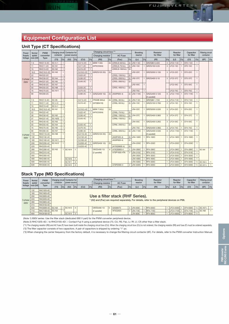
Equipment Configuration List
Stack Type (MD Specifications)
(Note 1) 690V series: Use the filter stack (dedicated 690 V part) for the PWM converter peripheral device.(Note 2) RHC132S-4D to RHC315S-4D : Contact Fuji if using a peripheral device (73, CU, R0, Fac, Lr, Rf, Lf, Cf) other than a filter stack.(*1) The charging resistor (R0) and AC fuse (F) have been built inside the charging circuit box (CU). When the charging circuit box (CU) is not ordered, the charging resistor (R0) and fuse (F) must be ordered separately.(*2) The filter capacitor consists of two capacitors. A pair of capacitors is shipped by ordering "1" pc.(*3) When changing the carrier frequency from the factory default, it is necessary to change the filtering circuit contactor (6F). For details, refer to the PWM converter Instruction Manual.
132160200220280315630710800
RHC132S-4DRHC160S-4DRHC200S-4DRHC220S-4DRHC280S-4DRHC315S-4DRHC630B-4DRHC710B-4DRHC810B-4D
SC-N3SC-N4
11
GRZG400 1Ω[2 parallel]
6SC-N12
SC-N14
3
3
RF4-630CRF4-710CRF4-800C
111
CF4-630CCF4-710CCF4-800C
LFC4-630CLFC4-710CLFC4-800C
1(*2)
1(*2)
1(*2)
SC-N7(*3)
SC-N811
111
LR4-630CLR4-710CLR4-800C
111
SA598473HF5G2655
Use a filter stack (RHF Series).* (52) and (Fac) are required separately. For details, refer to the peripheral devices on P68.
22
Unit Type (CT Specifications)PowerSupplyVoltage
3-phase200V
3-phase400V
3-phase400V
Nominalapplied
motor [kW]
PWMconverter
Type
Charging circuitcontactor
(73) Q'ty (R0) Q'ty(52) Q'ty (CU) Q'ty (Lr) Q'ty(Fac) Q'ty (Rf) Q'ty (Lf) Q'ty (Cf) Q'ty
Contactor forpower source
BoostingreactorAC Fuse
Resistorfor filter
Capacitorfor filter
Reactorfor filterCharging resistor
Charging circuit box (*1)
7.5111518.522303745557590
7.5111518.522303745557590110132160200220280315355400500630
(6F) Q'ty
Filtering circuitcontactor
PowerSupplyVoltage
Nominalapplied
motor [kW]
PWMconverter
Type
Charging circuitcontactor
(73) Q'ty (R0) Q'ty(52) Q'ty (CU) Q'ty (Lr) Q'ty(Fac) Q'ty (Rf) Q'ty (Lf) Q'ty (Cf) Q'ty
Contactor forpower source
BoostingreactorAC Fuse
Resistorfor filter
Capacitorfor filter
Reactorfor filterCharging resistor
Charging circuit box (*1)
(6F) Q'ty
Filtering circuitcontactor
RHC7.5-2CRHC11-2CRHC15-2CRHC18.5-2CRHC22-2CRHC30-2CRHC37-2CRHC45-2CRHC55-2CRHC75-2CRHC90-2C
RHC7.5-4CRHC11-4CRHC15-4CRHC18.5-4CRHC22-4CRHC30-4CRHC37-4CRHC45-4CRHC55-4CRHC75-4CRHC90-4CRHC110-4CRHC132-4CRHC160-4CRHC200-4CRHC220-4CRHC280-4CRHC315-4CRHC355-4CRHC400-4CRHC500-4CRHC630-4C
SC-5-1SC-N1SC-N2SC-N3
SC-N4SC-N5SC-N7SC-N8SC-N11
SC-05SC-4-0SC-5-1SC-N1
SC-N2SC-N2SSC-N3SC-N4SC-N5SC-N7SC-N8
SC-N11SC-N12
SC-N3
1111111111
1111
1111111
11
1
(80W 7.5Ω)(HF5C5504)
(GRZG120 2Ω)
(GRZG400 1Ω)
(TK50B 30ΩJ)(HF5B0416)
(80W 7.5ΩJ)(HF5C5504)
(GRZG120 2Ω)
(GRZG400 1Ω)
GRZG400 1Ω[2 parallel]
(3)
(3)
(3)
(3)
(3)
(3)
(3)
6SC-N14
SC-N16SC-N11SC-N12
1
133
CU7.5-2CCU11-2CCU15-2CCU18.5-2CCU22-2CCU30-2CCU45-2C
CU55-2CCU75-2CCU90-2C
CU7.5-4CCU15-4C
CU18.5-4CCU22-4CCU30-4CCU45-4C
CU55-4CCU75-4CCU90-4CCU110-4CCU132-4CCU160-4CCU200-4CCU220-4C
1111111
111
11
1111
11111111
GRZG80 0.42ΩGRZG150 0.2Ω
GRZG200 0.13Ω
GRZG400 0.1Ω
GRZG400 0.12Ω[2 parallel]GRZG80 1.74ΩGRZG150 0.79Ω
GRZG200 0.53Ω
GRZG400 0.38Ω
GRZG400 0.26Ω
GRZG400 0.38ΩGRZG400 0.53Ω[2 parallel]RF4-160C
RF4-220C
RF4-280CRF4-315CRF4-355CRF4-400CRF4-500CRF4-630C
33
3
3
6
33
3
3
3
36
1
1
111111
CF2-7.5CCF2-15C
CF2-22C
CF2-37C
CF2-55C
CF2-75CCF2-110C
CF4-7.5CCF4-15C
CF4-22C
CF4-37C
CF4-55C
CF4-75CCF4-110C
CF4-160C
CF4-220C
CF4-280CCF4-315CCF4-355CCF4-400CCF4-500CCF4-630C
LFC2-7.5CLFC2-15C
LFC2-22C
LFC2-37C
LFC2-55C
LFC2-75CLFC2-110C
LFC4-7.5CLFC4-15C
LFC4-22C
LFC4-37C
LFC4-55C
LFC4-75CLFC4-110C
LFC4-160C
LFC4-220C
LFC4-280CLFC4-315CLFC4-355CLFC4-400CLFC4-500CLFC4-630C
11
1
1
1
11
11
1
1
1
11
1
1
1111
1(*2)
1(*2)
SC-N4
SC-N4(*3)
SC-N7(*3)
1
11
11
1
1
1
11
11
1
1
1
11
1
1
111111
LR2-7.5CLR2-15C
LR2-22C
LR2-37C
LR2-55C
LR2-75CLR2-110C
LR4-7.5CLR4-15C
LR4-22C
LR4-37C
LR4-55C
LR4-75CLR4-110C
LR4-160C
LR4-220C
LR4-280CLR4-315CLR4-355CLR4-400CLR4-500CLR4-630C
11
1
1
1
11
11
1
1
1
11
1
1
111111
(CR2LS-50/UL)(CR2LS-75/UL)(CR2LS-100/UL)
(CR2L-150/UL)(CR2L-200/UL)(CR2L-260/UL)
(CR2L-400/UL)
(A50P600-4)
(CR6L-30/UL)(CR6L-50/UL)
(CR6L-75/UL)(CR6L-100/UL)(CR6L-150/UL)
(CR6L-200/UL)
(CR6L-300/UL)
(A50P400-4)(A50P600-4)
(A70QS800-4)A70QS800-4A70P1600-4TA
A70P2000-4
(2)(2)(2)
(2)(2)(2)
(2)
(2)
(2)(2)
(2)(2)(2)
(2)
(2)
(2)(2)
(2)22
2
Sta
ndar
dS
peci
ficat
ions
Com
mon
Spe
cific
atio
nsTe
rmin
alFu
ncti
ons
Pro
tect
ive
Func
tio
nsE
xter
nal
Dim
ensi
ons
Nam
es an
dFu
nctio
ns o
f Par
tsDe
dica
ted
Mot
orSp
ecifi
catio
nsEx
tern
al Di
mens
ions
of D
edica
ted M
otor
sPW
M co
nver
terRH
C-C,
RHC-
D se
ries
Wiri
ng D
iagr
amO
pti
ons
61

Options
Equipment Configuration List
Stack Type (LD Specifications)
(Note 1) 690V series: Use the filter stack (dedicated 690 V part) for the PWM converter peripheral device.(Note 2) RHC132S-4D to RHC315S-4D : Contact Fuji if using a peripheral device (73, CU, R0, Fac, Lr, Rf, Lf, Cf) other than a filter stack.(*1) The charging resistor (R0) and AC fuse (F) have been built inside the charging circuit box (CU). When the charging circuit box (CU) is not ordered, the charging resistor (R0) and fuse (F) must be ordered separately.(*2) The filter capacitor consists of two capacitors. A pair of capacitors is shipped by ordering "1" pc.(*3) When changing the carrier frequency from the factory default, it is necessary to change the filtering circuit contactor (6F). For details, refer to the PWM converter Instruction Manual.(*4) Contact Fuji.
1602002203153557108001000
RHC132S-4DRHC160S-4DRHC200S-4DRHC280S-4DRHC315S-4DRHC630B-4DRHC710B-4DRHC810B-4D
SC-N4 1 GRZG400 1Ω[2 parallel]
6SC-N12SC-N14SC-N16
333
RF4-710CRF4-800CRF4-1000C
111
CF4-710CCF4-800CCF4-1000C
LFC4-710CLFC4-800CLFC4-1000C
1(*2)
1(*2)
1(*2)
SC-N8
SC-N11/SF
1
1
111
LR4-710CLR4-800CLR4-1000C
111
HF5G2655
(*4)
Use a filter stack (RHF Series).* (52) and (Fac) are required separately. For details, refer to the peripheral devices on P68.
2
Unit Type (VT Specifications)PowerSupplyVoltage
3-phase200V
3-phase400V
3-phase400V
Nominalapplied
motor [kW]
PWMconverter
Type
Charging circuitcontactor
(73) Q'ty (R0) Q'ty(52) Q'ty (CU) Q'ty (Lr) Q'ty(Fac) Q'ty (Rf) Q'ty (Lf) Q'ty (Cf) Q'ty
Contactor forpower source
BoostingreactorAC Fuse
Resistorfor filter
Capacitorfor filter
Reactorfor filterCharging resistor
Charging circuit box (*1)
111518.522303745557590110111518.522303745557590110132160200220280315355400500
(6F) Q'ty
Filtering circuitcontactor
PowerSupplyVoltage
Nominalapplied
motor [kW]
PWMconverter
Type
Charging circuitcontactor
(73) Q'ty (R0) Q'ty(52) Q'ty (CU) Q'ty (Lr) Q'ty(Fac) Q'ty (Rf) Q'ty (Lf) Q'ty (Cf) Q'ty
Contactor forpower source
BoostingreactorAC Fuse
Resistorfor filter
Capacitorfor filter
Reactorfor filterCharging resistor
Charging circuit box (*1)
(6F) Q'ty
Filtering circuitcontactor
RHC7.5-2CRHC11-2CRHC15-2CRHC18.5-2CRHC22-2CRHC30-2CRHC37-2CRHC45-2CRHC55-2CRHC75-2CRHC90-2CRHC7.5-4CRHC11-4CRHC15-4CRHC18.5-4CRHC22-4CRHC30-4CRHC37-4CRHC45-4CRHC55-4CRHC75-4CRHC90-4CRHC110-4CRHC132-4CRHC160-4CRHC200-4CRHC220-4CRHC280-4CRHC315-4CRHC355-4CRHC400-4C
SC-N1SC-N2SC-N3
SC-N4SC-N5SC-N7SC-N8SC-N11
SC-N12SC-4-0SC-5-1SC-N1
SC-N2SC-N2SSC-N3SC-N4SC-N5SC-N7SC-N8
SC-N11SC-N12
SC-N14SC-N3
111
11111
1111
1111111
11
11
(80W 7.5Ω)(HF5C5504)
(GRZG120 2Ω)
(GRZG400 1Ω)(TK50B 30ΩJ)(HF5B0416)
(80W 7.5ΩJ)(HF5C5504)
(GRZG120 2Ω)
(GRZG400 1Ω)
GRZG400 1Ω[2 parallel]
(3)
(3)
(3)(3)
(3)
(3)
(3)
6SC-N14
SC-N16SC-N11
1
13
CU7.5-2CCU11-2CCU15-2CCU18.5-2CCU22-2CCU30-2CCU45-2C
CU55-2CCU75-2CCU90-2CCU7.5-4CCU15-4C
CU18.5-4CCU22-4CCU30-4CCU45-4C
CU55-4CCU75-4CCU90-4CCU110-4CCU132-4CCU160-4CCU200-4CCU220-4C
1111111
11111
1111
11111111
GRZG150 0.2Ω
GRZG200 0.13Ω
GRZG400 0.1Ω
GRZG400 0.12Ω[2 parallel]GRZG150 0.79Ω
GRZG200 0.53Ω
GRZG400 0.38Ω
GRZG400 0.26Ω
GRZG400 0.38ΩGRZG400 0.53Ω[2 parallel]RF4-160C
RF4-220C
RF4-280CRF4-315CRF4-355CRF4-400CRF4-500C
3
3
3
6
3
3
3
3
36
1
1
11111
CF2-15C
CF2-22C
CF2-37C
CF2-55C
CF2-75CCF2-110C
CF4-15C
CF4-22C
CF4-37C
CF4-55C
CF4-75CCF4-110C
CF4-160C
CF4-220C
CF4-280CCF4-315CCF4-355CCF4-400CCF4-500C
LFC2-15C
LFC2-22C
LFC2-37C
LFC2-55C
LFC2-75CLFC2-110C
LFC4-15C
LFC4-22C
LFC4-37C
LFC4-55C
LFC4-75CLFC4-110C
LFC4-160C
LFC4-220C
LFC4-280CLFC4-315CLFC4-355CLFC4-400CLFC4-500C
1
1
1
1
11
1
1
1
1
11
1
1
1111
1(*2)
SC-N4
SC-N4/SF
1
1
1
1
1
1
11
1
1
1
1
11
1
1
11111
LR2-15C
LR2-22C
LR2-37C
LR2-55C
LR2-75CLR2-110C
LR4-15C
LR4-22C
LR4-37C
LR4-55C
LR4-75CLR4-110C
LR4-160C
LR4-220C
LR4-280CLR4-315CLR4-355CLR4-400CLR4-500C
1
1
1
1
11
1
1
1
1
11
1
1
11111
(CR2LS-50/UL)(CR2LS-75/UL)(CR2LS-100/UL)
(CR2L-150/UL)(CR2L-200/UL)(CR2L-260/UL)
(CR2L-400/UL)
(A50P600-4)(CR6L-30/UL)(CR6L-50/UL)
(CR6L-75/UL)(CR6L-100/UL)(CR6L-150/UL)
(CR6L-200/UL)
(CR6L-300/UL)
(A50P400-4)(A50P600-4)
(A70QS800-4)A70QS800-4A70P1600-4TA
(2)(2)(2)
(2)(2)(2)
(2)
(2)(2)(2)
(2)(2)(2)
(2)
(2)
(2)(2)
(2)22
62

<Unit Type> RHC7.5-2C to RHC90-2C RHC7.5-4C to RHC220-4C
Basic Wiring Diagram
Cf2Cf1
Converter
M
U
V
W
Inverter
P(+)
(Note 2)
(Note 6)
(Note 4)
(Note 3)
220V or less (Note 1)
220V or less (Note 1)
N(-)i
Y5AFWD
CM
131211
j
eFX
f
c
R0T0
gh
ij
gh
R1T1
R2T2
RUN
R1
R0
6F
73
S1T1R0T073A
RDY
d 73C
RST
LrLf
CMY5C
30B
30C
30A
L1/R
L2/S
L3/T
CM
30Bb 30C
30A
e
gh i j
f
P(+)
N(-)
52
Rf
Cf2
52
cd
ab
RUN,READY RDY
52
52A
52T
RDY
6F
52TRUN
Stop
FXRUN52
73 52T
RUN
Fac
Fac
E(G)E(G)
X9(THR)
FX6FRUN52A 52
Converter
M
U
V
W
Inverter
P(+)
(Note 2)
(Note 4)
(Note 3)
(Note 6)
N(-)
Y5AFWD
CM
131211
eFX
f
c
R0T0R1T1
R2T2
RUN
R1
R0
6F
73
S1T1R0T073A
d 73C
RST
LrLf
CMY5C
30B
30C
30A
L1/R
L2/S
L3/T
CM
a 30Bb 30C
30A
e
gh i j
f
P(+)
N(-)
52-1 to 52-3
Rf
52
RUN
Fac
Fac
E(G)E(G)
Fdc
(DCF1)
(DCF2)
(DCF1)
(DCF2)
X9(THR)
a
(Note 5)
RDYcd
ab
RUN,READY RDY
52-1
52A
52T6F
52T
52-2
52-3
RUN
Stop
FXRUN52-1
52-2
52-3
FX52-352-252-152A 6FRUN52T73RDY
Electromagnetic contactor for filter circuit
LrLfCfRfR0Fac73
6F52
Symbol Part nameLrLfCfRfR0FacFdc73
6F52
Symbol Part name
<Unit Type> RHC280-4C to RHC400-4C
E(G)
MC Lf Lr
CU (Charge BOX)
L1/RL2/SL3/T
1
111213
23
G
456 N(-)
P(+) P(+)Fac
Fac
R0
N(-)R2T2
R1
R2T2
S1T1R0T0
73A73C
RUNRSTCM
UVW
FWDCM
131211
Y5AY5C
30B30C
30A
g
ef
hR1T1
X9(THR)CM30A30B30C
(Note 4)
(Note 3)
(Note 5)
f
E(G)
73
ab
R0T0
ij
RUNRUN RUN
Stop
RUN
FX52
ij
ab
73
gh
RUN,READY
52 or 73 (Note 2)
RfCf
e
M
MC RUN 73
FX
FX
Converter Inverter
E(G)
MC Lf LrL1/RL2/SL3/T N(-)
P(+) P(+)
N(-)R2T2
R1S1T1R0T0
73A73C
RUNRSTCM
UVW
FWDCM
131211
Y5AY5C
30B30C
30A
g
ef
hR1T1
X9(THR)CM30A30B30C
(Note 4)f
E(G)
ab
R0T0
ij
RUN
Stop
RUN
FX52
ij
ab
73
gh
RUN,READY
52 or 73 (Note 2)
RfCf
e
M
MC RUN 73
FX
FX
Converter Inverter
Fac
Fac
R0
73
220V or less (Note 1)
220V or less (Note 1)
Boosting reactorReactor for filter
Capacitor for filterResistor for filter
AC fuseCharging resistor
Electromagnetic contactor for charge circuitElectromagnetic contactor for power supply
Electromagnetic contactor for filter circuit
Boosting reactorReactor for filter
Capacitor for filterResistor for filter
AC fuseDC fuse
Charging resistor
Electromagnetic contactor for charge circuitElectromagnetic contactor for power supply
LrLfCfRfR0Fac73
SymbolBoosting reactorReactor for filter
Capacitor for filterResistor for filter
AC fuseCharging resistor
Electromagnetic contactor for charge circuit
Part nameLrLfCfRfR0Fac73
SymbolBoosting reactorReactor for filter
Capacitor for filterResistor for filter
AC fuseCharging resistor
Electromagnetic contactor for charge circuit
Part name
<Unit Type> RHC7.5-2C to RHC90-2C RHC7.5-4C to RHC220-4C*When adapting a charge BOX
<Unit Type> RHC500-4C to RHC630-4C
(Note 1) If the main power supply is 400V series, connect a step-down transformer to limit the voltage of the sequence circuit lower than 220V.
(Note 2) The auxiliary power supply input terminals for the PWM converter (R0, T0) must be connected to the main power supply via the contact“ b” of the charging circuit electromagnetic contactor (73 or MC). When applying ungrounded power supply, ground transformer must be set.
(Note 3) For the capacities FRN37VG1S-2 and FRN75VG1S-4 or higher and stack type inverter (all capacity range), connect the inverter fan power auxiliary input terminals (R1,T1) to the main power supply without passing through the contact "b" of 73 or MC.
(Note 4) Use the sequence that the run command signal is input in the inverter after the PWM converter becomes ready.
(Note 5) One of terminals (X1 to X9) on the inverter unit must be set to external alarm (THR).(Note 6) Be sure to connect the L1/R, L2/S, L3/T, R2, T2, R1, S1, and T1 terminals keeping the
phase sequence.
(Note 1) Connect a step-down transformer to limit the voltage of the sequence circuit lower than 220V.(Note 2) The auxiliary power supply input terminals for the PWM converter (R0, T0) must be connected to the
main power supply via the contact "b" of the charging circuit electromagnetic contactor (52). When applying ungrounded power supply, grounded transformer must be set.
(Note 3) Since the AC fan power supply receives power from R1 and T1 terminals, the power supply must be connected without passing through the contact “b” of 73 or MC.
(Note 4) Use the sequence that the run command signal is input in the inverter after the PWM converter becomes ready.
(Note 5) The 52T timer must be set to 1 sec.(Note 6) One of terminals (X1 to X9) on the inverter unit must be set to external alarm (THR).(Note 7) Be sure to connect the L1/R, L2/S, L3/T, R2, T2, R1, S1, and T1 terminals keeping the
phase sequence.(Note 8) Not available in the unit type inverter.
(Note 3)
(Note 5)
(Note 5)
(Note 8)
<Stack Type> RHC630S-4D to RHC800B-4D
Sta
ndar
dS
peci
ficat
ions
Com
mon
Spe
cific
atio
nsTe
rmin
alFu
ncti
ons
Pro
tect
ive
Func
tio
nsE
xter
nal
Dim
ensi
ons
Nam
es an
dFu
nctio
ns o
f Par
tsDe
dica
ted
Mot
orSp
ecifi
catio
nsEx
tern
al Di
mens
ions
of D
edica
ted M
otor
sPW
M co
nver
terRH
C-C,
RHC-
D se
ries
Wiri
ng D
iagr
amO
pti
ons
63

[Unit: mm]
[Unit: mm]
[Unit: mm]
[Unit: mm]
400Vseries
AAABBBCCC
226.2
226.2
226.2
1100
1400
1400
565
565
567.3
95
125135
135×3
RHC132S-4D RHC160S-4DRHC200S-4DRHC220S-4DRHC280S-4DRHC315S-4DRHC630B-4D (*1)RHC710B-4D (*1)RHC800B-4D (*1)
S-phase stack R, T-phase stack
*1) Each stack corresponds to one phase, and one set of the inverter consists of three stacks.
The keypad is attached only to the S phase.
RHC132S-4D to RHC200S-4D RHC132S-69D to RHC200S-69D
RHC220S-4D to RHC315S-4D RHC250S-69D to RHC315S-69D
RHC630B-4D to RHC800B-4D RHC630B-4D to RHC800B-4D
7075
191 17
17 455.3 38.5
1027
.891
.21.
6
MAX 565(D)550 11
Fixing plate
2.3
Fixing plate
1100
(H)
956
9463
5570
16030
MAX 226.2(W)220
2xM8
2xM8
7075
191 17
17 455.3 38.5
1367
.2
2.3
91.2
2.3
MAX 565(D)550 11
Fixing plate
Fixing plate
2xM8
2xM8
9463
5570
16030
MAX 226.2(W)220
1400
(H)
1190
455.3
7075
191 17
38.517
1367
.291.
2
MAX 565(D)550 11
2.3
Fixing plate
Fixing plate
2.3
1400
(H)
1190
9463
5570
16030
MAX 226.2(W)220
2xM8
2xM8
7075
191 17
17 455.3 38.5
1367
.291.
2
MAX 565(D)550 11
2.3
Fixing plate
2.3
Fixing plate
Options
External Dimensions
PWM converter main body (Unit Type)
RHC7.5-2CRHC11-2CRHC15-2CRHC18.5-2CRHC22-2CRHC30-2CRHC37-2CRHC45-2CRHC55-2CRHC75-2CRHC90-2CRHC7.5-4CRHC11-4CRHC15-4CRHC18.5-4CRHC22-4CRHC30-4CRHC37-4CRHC45-4CRHC55-4CRHC75-4CRHC90-4CRHC110-4CRHC132-4CRHC160-4CRHC200-4CRHC220-4CRHC280-4CRHC315-4CRHC355-4CRHC400-4CRHC500-4CRHC630-4C
A
B
BBBBCCA
B
BBBBBC
C
C
C
C
D
250
340
340375375375530680250
340
340375375375375530
530
680
680
880
999
226
240
240275275275430580226
240
240275275275275430
430
580
580
780
900
380
480
550615740740750880380
480
550550675675740740
1000
1000
1400
1400
1550
358
460
530595720720720850358
460
530530655655720710
970
970
1370
1370
1520
245
255
255270270270285360245
255
255270270270270315
360
360
450
450
500
125
145
145145145145145220125
145
145145145145145175
220
220
285
285
313.2
2
2
2222232
2
222222
2
3
3
4
4
10
10
10101010151510
10
101010101015
15
15
15
15
15
10
10
10101010151510
10
101010101015
15
15
15
15
15
12.5
24
2936424470
11512.5
24
293438394870
100
140
320
410
525
PWM converter main body (Stack Type)
1400
(H)
1190
9463
5570
16030
MAX 226.2(W)220
2xM8
2xM8
Fig. A
Fig. D
WW1 D1
C
D
H1 H
2- B
Fig. BWW1
H1 H
DD1
C
n- B 4- 18Lifting hall
Fig. CW D
D1W1
H1 H
C
n- B W
W1
C
H1 H
D1Dn- B
64
PWM converter TypeDimensions [mm]
W W1 H1 D D1 n B C
Approx.weight [kg]Fig
H
200Vseries
400Vseries
Fig. A
Fig. C
Fig. BPWM converter Type
Dimensions [mm]
W H DFig
Approx.weight [kg]Series

External Dimensions
200Vseries
MAX.MAX. D2 NPFor terminal Mφ
D1D
MAX
. H
W1
X1 X2 Y1 Y2 Z1 Z2
W MAX.D2For terminal Mφ
Y1 Z1X1
Y2 Z2X2
MAX. W
MAX
. H
W1
NP
D1D
MAX. D2For terminal Mφ
D1D
MAX. W
MAX
. H
X2 Y2 Z2
X1 Y1 Z1
W1
NP
W1
MAX.W
Z1Y1X1
Z2Y2X2
MAX
.HD2
40 N1
ND1
D
40400Vseries
200Vseries
Pressurizationreactor Type
Dimensions [mm]
W
Approx.weight [kg]Fig
LR2-7.5CLR2-15CLR2-22CLR2-37CLR2-55CLR2-75CLR2-110CLR4-7.5CLR4-15CLR4-22CLR4-37CLR4-55CLR4-75CLR4-110CLR4-160CLR4-220CLR4-280CLR4-315CLR4-355CLR4-400CLR4-500CLR4-630CLR4-710CLR4-800CLR4-1000C
ABCCCCCBACCCCCCCCCCCCDEEE
180195240285285330345180195240285285330345380450480480480480525600645690770
W1
75758095951101157575809595110115125150160160160160175200215230255
H
205215340420420440500205215340405415440490550620740760830890960640730850940
D
105131215240250255280105131215240250255280300330330340355380410440440450550
D1
8511018020521522024585110180205215220245260290290300315330360390390400480
D2
9513014515016016518590120120130145150170185230240250255260290285295290340
K
7710121212127710121212121515151515191919191923
M
M5M8M8M10M12M12M12M4M5M6M8M10M10M12M12M12M16M16M16M16M16
----
N
---------------------
75100100100
N1
---------------------
17.5303030
121833505870100121833505870100140200250270310340420450510600950
<Boosting reactor>
W1MAX. W
Nameplate
MAX
.H
X2 Y2 Z2
X1 Y1 Z1
D1D
D2
400Vseries
Filtering reactor type
Dimensions [mm]
W
Approx.weight [kg]Fig
LFC2-7.5CLFC2-15CLFC2-22CLFC2-37CLFC2-55CLFC2-75CLFC2-110CLFC4-7.5CLFC4-15CLFC4-22CLFC4-37CLFC4-55CLFC4-75CLFC4-110CLFC4-160CLFC4-220CLFC4-280CLFC4-315CLFC4-355CLFC4-400CLFC4-500CLFC4-630CLFC4-710CLFC4-800CLFC4-1000C
BBBBBBCAAABBBCCDDDDDDEEEE
125125125150175195255125125125150175195255255300330315315345345435480480480
W1
404040606080854040406060808585100110105105115115145160160160
H
100100100115145200230100100100115145200220245320320365395420480550570600700
D
859393103110120118859393108110113113137210230230235235240295295320320
D1
67757585901009567757590909390110180195195200200205255255270270
D2
8590105125140150165759095110120130145150170195200210235240200215220240
K
666667766666771010121212121215151515
M
M5M8M8M10M12M12M12M4M5M6M8M10M10M12M12M12M16M16M16M16M16
----
N
---------------------
75100100100
N1
---------------------
17.5303030
2.22.53.05.08.013202.22.53.05.08.0121922354348536072175190220240
<Filtering reactor>
MAX.D2 NameplateFor terminal Mφ For terminal Mφ For terminal Mφ
D1D
MAX.D2 Nameplate
D1D
MAX.D2
D1D
X1 X2 Y1 Y2 Z1 Z2
MAX.W
MAX
. H
W1
Y1 Z1X1
Y2 Z2X2
W1
MAX. W
MAX
. H
X2 Y2 Z2
X1 Y1 Z1
MAX. WNP
MAX
. H
W1
Fig. D Fig. E
X2 Y2 Z2
X1 Y1 Z1
MAX. WNameplate
MAX
. H
W1
MAX.D2For terminal Mφ
D1D
W1
MAX.W
Z1Y1X1
Z2Y2X2
MAX
.H
D2
40 N1
N
D1
D
40
40 N1
N
40
Fig. A Fig. B
Fig. C
Fig. E
Fig. D
Fig. A Fig. B Fig. C
Sta
ndar
dS
peci
ficat
ions
Com
mon
Spe
cific
atio
nsTe
rmin
alFu
ncti
ons
Pro
tect
ive
Func
tio
nsE
xter
nal
Dim
ensi
ons
Nam
es an
dFu
nctio
ns o
f Par
tsDe
dica
ted
Mot
orSp
ecifi
catio
nsEx
tern
al Di
mens
ions
of D
edica
ted M
otor
sPW
M co
nver
terRH
C-C,
RHC-
D se
ries
Wiri
ng D
iagr
amO
pti
ons
65
4- K Elongated hole4- K Elongated hole
4- K Elongated hole4- K Elongated hole
4- K
4- K
4- K
4- 15
4- 15
4- K
4- K 4- K 4- 15

200Vseries
200Vseries
200Vseries
Options
W1
W
DD1
mounting hole
E E
H
3-I
mounting holemounting hole
mounting hole
D
W1
W
E E
H
3-I
H1
<Filtering capacitor>
W2
W1
W
D2D1
D
H2
H1 NP
D2D1
D
W1W 4−φ15
H2
H1
2−M12 eye bolt Terminal
Earth terminal(M6)
Terminal
D2
D1
DM12 eye bolt
H2
H1
W1
W
<Filtering resistor>
<Charging circuit box>
DD1
W
H2
H4
H3
H1 H
W1
C
400Vseries
Filtering capacitor typeDimensions [mm]
W
Approx.weight [kg]Fig
CF2-7.5CCF2-15CCF2-22CCF2-37CCF2-55CCF2-75CCF2-110CCF4-7.5CCF4-15CCF4-22CCF4-37CCF4-55CCF4-75CCF4-110CCF4-160CCF4-220CCF4-280CCF4-315CCF4-355CCF4-400CCF4-500CCF4-630CCF4-710CCF4-800CCF4-1000C
AAAAAAAAAAAAAAABBBBBBBBBB
165205280280280280280165165205205205205205280435435435435435435435435435435
W1
150173265265265265265150150190190190190190265400400400400400400400400400400
H
185245215235340235340135215185205245205245260310350460520610310460520610610
H1
---------------
125165275335425125275335425425
D
707090909090907070707070707090100100100100100100100100100100
D1
404055555555554040404040404055----------
E
30303030803080303030303030308080808080808080808080
F
777777777777777
15 x 20 long hole15 x 20 long hole15 x 20 long hole15 x 20 long hole15 x 20 long hole15 x 20 long hole15 x 20 long hole15 x 20 long hole15 x 20 long hole15 x 20 long hole
I
M5M5M5M5M6M5M8M5M5M5M5M5M5M5M6M12M12M12M12M12M12M12M12M12M12
1.93.55.56.08.56.08.51.32.32.52.93.52.93.56.0
13.015.020.023.027.013.020.023.027.027.0
400Vseries
Charging circuit box typeDimensions [mm]
W
Approx.weight [kg]
CU7.5-2CCU11-2CCU15-2CCU18.5-2CCU22-2CCU30-2CCU45-2CCU55-2CCU75-2CCU90-2CCU7.5-4CCU15-4CCU18.5-4CCU22-4CCU30-4CCU45-4CCU55-4CCU75-4CCU90-4CCU110-4CCU132-4CCU160-4CCU200-4CCU220-4C
270
300330
430
270
300
330
430
W1170
200230
330
170
200
230
330
H300
310310
560
300
310
310
560
H1285
295295
536
285
295
295
536
H2270
280280
510
270
280
280
510
H37.5
7.57.5
12
7.5
7.5
7.5
12
H415
1515
25
15
15
15
25
D D1 C100
110130
150
100
110
130
150
2.4
2.42.4
3.2
2.4
2.4
2.4
3.2
6
66
10
6
6
6
10
6
78
17205.5
6
7
8
18
20
Mounting bolt
M5
M5M5
M8
M5
M5
M5
M8
400Vseries
Filtering resistor typeDimensions [mm]
WQ'ty
Approx.weight [kg]
Approx.weight [kg]Fig
GRZG80 0.42ΩGRZG150 0.2ΩGRZG200 0.13ΩGRZG400 0.1ΩGRZG400 0.12ΩGRZG80 1.74ΩGRZG150 0.79ΩGRZG200 0.53ΩGRZG400 0.38ΩGRZG400 0.26ΩGRZG400 0.53ΩRF4-160CRF4-220CRF4-280CRF4-315CRF4-355CRF4-400CRF4-500CRF4-630CRF4-710CRF4-800CRF4-1000C
AAAAAAAAAAAB
C
C
167247306411411167247306411411411400
655
655
755
W1
148228287385385148228287385385385370
625
625
725
W2
115195254330330115195254330330330
-
-
-
-
H1
2222224040222222404040240
240
440
440
H2
324040464632323246464655
55
55
55
D
3333334747333333474747470
470
530
530
D1
2626264040262626404040460
460
520
520
D2
666
9.59.5666
9.59.59.5320
320
320
320
C
5.58.28.28.28.25.55.55.58.28.28.2-
-
-
-
0.190.30.350.850.850.190.300.350.850.850.8522253135363841707080-
33333611111111111
External Dimensions
Fig. A
Fig. A
Fig. C
Fig. B
Fig. B
66
2- C
4- K mounting hole
4- F mounting hole 4- F mounting hole
C

200Vseries
500±10
4.534
5 140150
φ4.5
80W 7.5Ω (HF5C5504)
120
φC
W2W1W
D2D1D
H2
H1
10203080
4.5×8.5
712.5
32
500±10
TK50B 30ΩJ (HF5B0416)
120
Note) "SA598473" is used for the stack type inverter. For details, refer to the FRENIC-VG User's Manual (Stack Type Edition).
<Charger resistor>
Charger resistor typeDimensions [mm]
W
Approx.weight [kg]Fig
GRZG120 2ΩGRZG400 1ΩTK50B 30ΩJ (HF5B0416)80W 7.5Ω (HF5C5504)
AABC
217411
--
W1198385
--
W2165330
--
H12240--
H23239--
D3347--
D12240--
D26
9.5--
C5.55.5--
250850150180
[Unit: mm]
[Unit: mm]
400Vseries
Fuse typeDimensions [mm]
W
Approx.weight [kg]Fig
CR2LS-50/ULCR2LS-75/ULCR2LS-100/ULCR2L-150/ULCR2L-200/ULCR2L-260/ULCR2L-400/ULA50P600-4CR6L-30/ULCR6L-50/ULCR6L-75/ULCR6L-100/ULCR6L-150/ULCR6L-200/ULCR6L-300/ULA50P400-4A50P600-4A70QS800-4A70P1600-4TAA70P2000-4HF5G2655SA598473
A
AA
ABA
A
A
BBBCCDE
56
8085
95113.5
76
95
107
110113.5180.2
----
W1
42
5860
7081.75
62
70
82
78.681.75129.4
----
W2
26
29.530
3156.447
40
43
53.156.472.2
----
H
18.5
30.533.5
42-
18.5
34
42
-------
D
17.5
2730
3750.817.5
30
37
38.150.863.5
----
D1
12
2025
3038.112
25
30
25.438.150.8
----
G
2
33.2
46.42
3.2
4
6.46.49.5----
E
6.5x8.5
9x1111x13
11x1310.3x18.2
6.5x8.5
11x13
11x13
10.3x18.410.3x18.213.5x18.3
----
0.03
0.100.13
0.220.6042
150
246
300600
11007400800047004500
<Fuse>
160.5 74.5
8632
150
6
90.25
150
20
190
7458
4-×φ15
W
W1
W2
2-E
DD1
G
H
W
W1
W2
2-E
G
DD1
8932
19.1
12711
19 10
3.2 237.3 3.2
12.7 12.7148.4
275.4
97.6
1.6
1.6
41.2
15.8
8349
90.754
6
74.5
166
86
150
2019
0
15032 4xφ15
[Unit: mm]
[Unit: mm]
[Unit: mm]
External Dimensions
Fig. A
Fig. A
Fig. C
Fig. E
Fig. D
Fig. B
Fig. B Fig. C
Sta
ndar
dS
peci
ficat
ions
Com
mon
Spe
cific
atio
nsTe
rmin
alFu
ncti
ons
Pro
tect
ive
Func
tio
nsE
xter
nal
Dim
ensi
ons
Nam
es an
dFu
nctio
ns o
f Par
tsDe
dica
ted
Mot
orSp
ecifi
catio
nsEx
tern
al Di
mens
ions
of D
edica
ted M
otor
sPW
M co
nver
terRH
C-C,
RHC-
D se
ries
Wiri
ng D
iagr
amO
pti
ons
67

Options
Standard specifications
132160132−
282
1552.5kHz or 5kHz
IP00 open type75dB (Condition: A range distance of 1 m) (*4)
200220160200384
195
280−−−
489
230
315−
280315619
250
RHF160S-4D RHF220S-4D RHF280S-4D RHF355S-4D
Applicable converter typeRHF S-4D
Rated current [A]
Allowable carrier frequency Approx. weight [kg]EnclosureNoise level
Powersupplyvoltage
Main powerPhase, Voltage, FrequencyFan power supplyPhase, Voltage, FrequencyFrequency variation
MD application
LD application
400V series200V series
3-phase 400V seriesType
3-Phase 380 to 440V/50Hz, 380 to 460V/60Hz
Single-phase 380 to 440V/50Hz, 380 to 460V/60Hz (*1) Single-phase 200 to 220V/50Hz, 200 to 230V/60Hz (*2) Voltage: +10 to -15%, Frequency: +5 to -5%, Unbalance ratio between voltage phases: within 2% (*3)
Filter stack : RHF-D series (Stack Type)
This is a dedicated filter stack for the high power factor PWM converter with power regenerative function (RHC-D Series).This device is used in combination with the RHC-D Series, and peripheral devices (filtering circuit, boosting circuit, charging circuit) required by the PWM converter have been combined into a single unit.Peripheral device wire reduction and attachment space saving is possible.A stack type with same shape as the inverter (stack type) and PWM converter (RHC-D) has been adopted. This has been effective in making panels more compact.
68

Symbol Name
Connects a 3-phase power supply.Connect to PWM converter power input terminals L1/R, L2/S, and L3/T.Connects a 3-phase power supply.Ground terminal for filter stack chassis (housing).To be used as supply input of AC cooling fan inside of filter stack.Used when 200 VAC is input as the filter stack internal AC cooling fan power supply.When inputting 200 VAC, remove the shorting wires between terminals R11 and R12 and T11 and T12, and connect them to terminals R12 and T12.Change the terminal connection based on the fan power supply input terminal.For details, refer to the filter stack (RHF-D) Instruction Manual.Input control signal for contactor for charging circuit.<Rated capacity of coil> <400V series> At power on ... 200 V/50 Hz: 120 VA, 220 V/60 Hz: 135 VA At power hold ... 200 V/50 Hz: 12.7 VA, 220 V/60 Hz: 12.4 VA <690V series> At power on ... 200V/50Hz: -VA, 220V/60Hz: -VA At power hold ... 200V/50Hz: -V, 220V/60Hz: -VAAuxiliary contact of contactor for charging circuitTo be used as signal for operational check of charging circuit.Contact rating: 24 VDC 3 A * Min. working voltage/current: 5 VDC 3 mASignal is output when internal parts of filter stack are overheated.Contact rating: 24 VDC, 3 mA /max
Terminal Functions
Functions
L1,L2,L3U0,V0,W0L4,L5,L6E(G)R3,T3
R11,R12T11,T12
U1,U2
73-173-2
ONAONBONC12
Main power inputFilter outputCharging circuit inputGroundingFan power supply input
Fan power supply input (at input of 200 V)
Power supply voltage switching terminal
Control input of contactor for charging circuit
Operation signal of chargingcircuit
Alarm output
Main circuit
Input signal
Output signal
Sta
ndar
dS
peci
ficat
ions
Com
mon
Spe
cific
atio
nsTe
rmin
alFu
ncti
ons
Pro
tect
ive
Func
tio
nsE
xter
nal
Dim
ensi
ons
Nam
es an
dFu
nctio
ns o
f Par
tsDe
dica
ted
Mot
orSp
ecifi
catio
nsEx
tern
al Di
mens
ions
of D
edica
ted M
otor
sGu
idelin
es fo
rSu
ppres
sing H
armon
icsFi
lter
sta
ckR
HF-
D s
erie
sW
iring
Dia
gram
Op
tio
ns
69

* AC fuses and microswitches are manufactured by Cooper Bussmann, but can also be ordered from Fuji.
Options
Wiring Diagram
Peripheral Devices
3-phase 400V seriesMD application
111111
300350500500600700
SC-N8SC-N11SC-N12SC-N12SC-N14SC-N14
111111
170M5446170M654670M654770M6547
170M6499170M6500
333333
170H3027 3
Filter stack (RHF-D) MCCB, ELCBRated current [A]Type Q'ty
Electromagnetic contactor (52)Type Q'ty
AC fuse (Fac)Type Q'ty
MicroswitchType Q'ty
PWM converter(RHC-D)
RHC132S-4DRHC160S-4DRHC200S-4DRHC220S-4DRHC280S-4DRHC315S-4D
LD application
RHF160S-4D RHF220S-4D RHF220S-4D RHF355S-4D RHF355S-4D
11111
350500500700800
SC-N11SC-N12SC-N12SC-N14SC-N14
11111
170M5446170M654670M6547
170M6499170M6500
33333
170H3027 3
Filter stack (RHF-D) MCCB, ELCBRated current [A]Type Q'ty
Electromagnetic contactor (52)Type Q'ty
AC fuse (Fac)Type Q'ty
MicroswitchType Q'ty
PWM converter(RHC-D)
RHC132S-4DRHC160S-4DRHC200S-4DRHC280S-4DRHC315S-4D
(Note 1) Connect a step-down transformer, and set the sequence circuit voltage as shown in the basic wiring diagram.(Note 2) The auxiliary power supply input terminals (R0, T0) for the PWM converter and inverter must be connected to the main power supply via contact "b" on the charging circuit electromagnetic contactor (52) or via an
isolation transformer. When using an ungrounded power supply, it is necessary to install an isolation transformer.(Note 3) Since the AC fan power supply receives power from R1 and T1 terminals, the power supply must be connected without passing through the 73 or 52 contact “b”.(Note 4) Use the sequence in which the run command signal is input to the inverter after the PWM converter is ready.(Note 5) The 52T timer must be set to 1 sec.(Note 6) If using a microswitch to detect AC fuse burnout, set the PWM converter X1 terminal to external alarm (THR), and then connect all microswitches in series.(Note 7) Ensure to align the phase sequence when connecting the L1/R, L2/S, L3/T, R2, T2, R1, S1, and T1 terminals.(Note 8) When inputting 200 VAC for the fan power supply, remove the shorting wires between terminals R11 and R12 and T11 and T12, and connect them to terminals R12 and T12. These are dedicated terminals for internal fan power supply, and must not be used for other applications.(Note 9) The 73T timer must be set to 5 sec.(Note 10) If using the 400V series, connect Fdc (fuse) to the P(+) side. Fdc (fuse) is not required for the N(-) side. If using the 690V Series, connect Fdc (fuse) to the P(+) and N(-) sides. (Connect two microswitches in series.)
ACFAN
DCF1
DCF2
X1(THR)
CM
L3/T
L2/S
L1/R
73A73CRUN
RUN
RUN
RUN FX
RST
CMFX
30A
Y5CY5A
30B
52T52T
52T73T73T
RDY
RDY RDY
52A
52A200V/50Hz220V/60hz
52
5252
52
52
52
30C
P(+)
N(-)
E(G)
E(G)
R1
U0
V0
W0
S1
R0T1
T0
Inverter stackVG1 series
PWM converter stackRHC-D series
Filter stackRHF-D series
Microswitch fordetection of opencircuit in DC fuse
Microswitch fordetection of open circuit in AC fuse
RUNRUN READY
Stop
Isolation transformer
DCF1
DCF2
feFX
X9(THR)
R1
R0
131211
CM
30A30B30C
CM
FWD
W
MV
UP(+)
N(-)
E(G)
T1
T0gnm
h
a
i
k
l
j
lk
b
(Note10)
(Note10)
Fdc
Fdc
(Note3)
(Note6)
(Note1)
(Note8)
(Note2)
(Note7)
(Note9)
(Note5)
cd
mn
gh
cd
ab
ij
1
2
73
73
73
73
ONAONB
ONC
R11
T3R3
L3
L2
L1
L6L5
Lf
RfCf
Lr
L4 R0
R12T11 FUS2
FUS1
T1273-1
73-2
Fac
Fac
FacPow
er s
uppl
y
U3U2U1
RHF160S-4D RHF160S-4D RHF220S-4D RHF220S-4D RHF280S-4D RHF355S-4D
70
LrLfCfRfR0FacFdc7352
SymbolBoosting reactorFiltering reactor
Filtering capacitorFiltering resistorCharger resistor
AC fuseDC fuse
Magnetic contactor for charging circuitMagnetic contactor for power supply
Part name

Dimensions
Fig. A Fig. B
W H D
[Unit:mm]FigFilter stack type
A
B
226.2
226.2
1166
1400
565
565
RHF160S-4DRHF220S-4DRHF280S-4DRHF355S-4D
RHF160S-4D , RHF220S-4D
[Unit:mm]
RHF280S-4D , RHF355S-4D
[Unit:mm]
227.5 222.8 41
7075
191 20
20
1367
.291
.2
MAX 565(D)550 11
2.3
Fixingplate
Fixingplate
2.3
1400
(H)
1190
94636681
16030
MAX 226.2(W)220
2xM8
2xM8
Fixingplate
Fixingplate
4 550 11MAX565(D)
2.3
2.3
91.2
1133
.2
7075
450.3 41(SCL 1:8)63 94
668195
611
66(H
)
MAX 226.2(W)220
30 160
2xM8
2xM8
191 20
20
400Vseries
Sta
ndar
dS
peci
ficat
ions
Com
mon
Spe
cific
atio
nsTe
rmin
alFu
ncti
ons
Pro
tect
ive
Func
tio
nsE
xter
nal
Dim
ensi
ons
Nam
es an
dFu
nctio
ns o
f Par
tsDe
dica
ted
Mot
orSp
ecifi
catio
nsEx
tern
al Di
mens
ions
of D
edica
ted M
otor
sGu
idelin
es fo
rSu
ppres
sing H
armon
icsFi
lter
sta
ckR
HF-
D s
erie
sW
iring
Dia
gram
Op
tio
ns
71

Options
Diode rectifier (RHD-D) (Stack Type)
Standard Specifications: MD Specification for Medium Loads
227
200
600110248
125
150% of continuous rating for 1 minuteDC 513 to 679V (variable with input power supply voltage and load)
3-phase, 380 to 440V/50Hz, 380 to 480V 60Hz
Single-phase, 380 to 440V/50Hz, 380 to 480V 60Hz (*3)Single-phase, 200 to 220V/50Hz, 200 to 230V 60Hz (*4)Voltage: -15 to +10%, Frequency: +5 to -5%, Voltage unbalance: 2% or less (*5)
IP00 open type
353
315
945180388
160
Continuous rating [kW] (*2)Nominal applied inverter/motor capacity (*2)Overload ratingVoltage
Max. connection capacity [kW] (*1)(*2)Min. connection capacity [kW] (*2)Required power supply capacity [kVA]
Main power Phase, Voltage, FrequencyAuxiliary input for fan powerPhase, Voltage, FrequencyVoltage/frequency variation
Approximate weight [kg] Enclosure
400V series200V series
Three-phase 400V seriesRHD200S-4D RHD315S-4D Model
Output
Input powersupply
Output
Input powersupply
252
220
660132270
125
150% of continuous rating for 1 minuteDC 776 to 1091V (variable with input power supply voltage and load)
3-phase, 575 to 690V/50Hz, 60Hz
Single-phase, 660 to 690V, 50/60Hz, 575 to 600V, 50/60Hz (*3)Single-phase, 200 to 220V/50Hz, 200 to 230V/60Hz (*4)Voltage: -15 to +10%, Frequency: +5 to -5%, Voltage unbalance: 2% or less (*5)
IP00 open type
504
450
1350250549
160
Continuous rating [kW] (*2)Nominal applied inverter/motor capacity (*2)Overload ratingVoltage
Max. connection capacity [kW] (*1)(*2)Min. connection capacity [kW] (*2)Required power supply capacity [kVA]
Main power Phase, Voltage, FrequencyAuxiliary input for fan powerPhase, Voltage, FrequencyVoltage/frequency variation
Approximate weight [kg] Enclosure
690V series200V series
Three-phase 690V seriesRHD220S-69D RHD450S-69D Model
*1) This is the total connectable inverter capacity due to initial charging circuit restrictions. However, the capacity that can be run simultaneously is the continuous capacity.*2) 400V series: This is the value when the power supply voltage is 400 V. If the power supply voltage is less than 400 V, it is necessary to reduce the capacity. A reduction in capacity is also required if connecting multiple inverters. 690V series: This is the value when the power supply voltage is 690 V. If the power supply voltage is less than 690 V, it is necessary to reduce the capacity. A reduction in capacity is also required if connecting multiple inverters.*3) 400V series: Diode rectifier internal terminal (U1, U2) switching is required if the power supply is 380 to 398 V, 50Hz or 380 to 430 V, 60Hz. 690V series: Diode rectifier internal terminal (U1, U2) switching is required if the power supply is 575 to 600 V, 50Hz/60Hz.*4) Power can also be supplied from a 200 V power supply. For details, refer to the diode rectifier (RHD-D) Instruction Manual.*5) Interphase unbalance rate (%) = max. voltage [V] - min. voltage [V] × 67 3-phase average voltage
Converter typeDiode rectifier converts AC power to DC power, then supplies DC power to inverter.
Substantial applicable capacityA large capacity system may be constructed by connecting converters in parallel.(3-parallel, 12-pulse rectifying system: using 6 units of diode rectifiers)•MD specification: 1450kW (400V series), 2000kW (690V series)•LD specification: 1640kW (400V series)
Suppression of harmonic currents *Equipped with DC reactor as standardThis unit is equipped with DC reactor for suppression of the harmonic currents. Further suppression of harmonic currents is made possible by creating a 12-pulse rectifier system in combination with power transformer, when connecting more than one unit in parallel.
Control deviceA braking unit and braking resistor are available as options (externally attached).Capacity can be selected based on the amount of regenerative (braking) energy, facilitating a compact system construction.
72

Standard Specifications: LD Specification for Light Loads
247
220
600110271
125
110% of continuous rating for 1 minuteDC 513 to 679V (variable with input power supply voltage and load)
3-phase, 380 to 440V/50Hz, 380 to 480V 60Hz
Single-phase, 380 to 440V/50Hz, 380 to 480V 60Hz (*3)Single-phase, 200 to 220V/50Hz, 200 to 230V 60Hz (*4)Voltage: -15 to +10%, Frequency: +5 to -5%, Voltage unbalance: 2% or less (*5)
IP00 open type
400
355
1065180435
160
Three-phase 400V seriesRHD200S-4D RHD315S-4D Model
280
250
750132308
125
110% of continuous rating for 1 minuteDC 776 to 976V (variable with input power supply voltage and load)
3-phase, 575 to 690V/50Hz, 60Hz
Single-phase, 660 to 690V, 50/60Hz, 575 to 600V, 50/60Hz (*3)Single-phase, 200 to 220V/50Hz, 200 to 230V/60Hz (*4)Voltage: -15 to +10%, Frequency: +5 to -5%, Voltage unbalance: 2% or less (*5)
IP00 open type
Three-phase 690V seriesRHD220S-69D Model
Continuous rating [kW] (*2)Nominal applied inverter/motor capacity (*2)Overload ratingVoltage
Max. connection capacity [kW] (*1)(*2)Min. connection capacity [kW] (*2)Required power supply capacity [kVA]
Main power Phase, Voltage, FrequencyAuxiliary input for fan powerPhase, Voltage, FrequencyVoltage/frequency variation
Approximate weight [kg] Enclosure
400V series200V series
Output
Input powersupply
Continuous rating [kW] (*2)Nominal applied inverter/motor capacity (*2)Overload ratingVoltage
Max. connection capacity [kW] (*1)(*2)Min. connection capacity [kW] (*2)Required power supply capacity [kVA]
Main power Phase, Voltage, Frequency 690VAuxiliary input for fan powerPhase, Voltage, FrequencyVoltage/frequency variation
Approximate weight [kg] Enclosure
400V series200V series
Output
Input powersupply
*1) This is the total connectable inverter capacity due to initial charging circuit restrictions. However, the capacity that can be run simultaneously is the continuous capacity.*2) 400V series: This is the value when the power supply voltage is 400 V. If the power supply voltage is less than 400 V, it is necessary to reduce the capacity. A reduction in capacity is also required if connecting multiple inverters. 690V series: This is the value when the power supply voltage is 690 V. If the power supply voltage is less than 690 V, it is necessary to reduce the capacity. A reduction in capacity is also required if connecting multiple inverters.*3) 400V series: Diode rectifier internal terminal (U1, U2) switching is required if the power supply is 380 to 398 V, 50Hz or 380 to 430 V, 60Hz. 690V series: Diode rectifier internal terminal (U1, U2) switching is required if the power supply is 575 to 600 V, 50Hz/60Hz.*4) Power can also be supplied from a 200 V power supply. For details, refer to the diode rectifier (RHD-D) Instruction Manual.*5) Interphase unbalance rate (%) = max. voltage [V] - min. voltage [V] × 67 3-phase average voltage
Sta
ndar
dS
peci
ficat
ions
Com
mon
Spe
cific
atio
nsTe
rmin
alFu
ncti
ons
Pro
tect
ive
Func
tio
nsE
xter
nal
Dim
ensi
ons
Nam
es an
dFu
nctio
ns o
f Par
tsDe
dica
ted
Mot
orSp
ecifi
catio
nsEx
tern
al Di
mens
ions
of D
edica
ted M
otor
sGu
idelin
es fo
rSu
ppres
sing H
armon
icsD
iode
rec
tifie
rR
HD
-D s
erie
sW
iring
Dia
gram
Op
tio
ns
73

Options
Intermediate DC voltage
DC580V±8VDC470V±8V
73A to 73C output signal
Td=0.5 to 1.5sec
ON
Symbol Name
Connect to 3-phase power supply.Connect to inverter power input terminals P (+) and N (-).Ground terminal of diode rectifier chassis (case)To be used as supply input of AC cooling fan inside of diode rectifier.Use if inputting 200 VAC for the diode rectifier internal AC cooling fan power supply.When inputting 200 VAC, remove the shorting wires between terminals R11 and R12 and T11 and T12, and connect them to terminals R12 and T12.Coil supply of charging circuit contactor for charging circuit.Not to be used as power supply for external circuit.Change the terminal connection based on the power supply connected to the fan power supply input terminal.For details, refer to the diode rectifier (RHD-D) Instruction Manual.Input control signal for charging circuit contactor.Control signal may also be input externally. • Rated capacity of coil <400V series> At power on ... 200V/50Hz: 380VA, 220V/60Hz: 460VA At power hold ... 200V/50Hz: 26.6VA, 220V/60Hz: 26.8VA <690V series> At power on ... 470V/50Hz: 235VA, 220V/60Hz: 500VA At power hold ... 40.0V/50Hz: 20.0VA, 220V/60Hz: 39.0VAControl signal of charging circuitCan also be used for external sequence circuits.Contact rating : 250 VAC 0.5 A cos =0.3, 30 VDC 0.5 AAuxiliary contact of charging circuit contactor.To be used as signal for operational check of charging circuit.Contact rating: 24 VDC 3 A * Min. working voltage/current: 5 VDC 3 mASignal is output when internal parts of diode rectifier are overheated.Contact rating: 24 VDC, 3 mA
Terminal Functions
Functions
L1/R, L2/S, L3/TP(+), N(-)E(G)R1, T1
R11, R12T11, T12
73R73T
U1, U2
73-173-2
73A73C
ONAONC
12
Main circuit
Input signal
Output signal
(*1) Refer to the basic wiring diagram for the connection method. Connect contactors after initial charging is complete. Furthermore, do not open contactors while the inverter is running. Failure to observe this may result in damage to the initial
charging circuit.(*2) An output signal timing chart and the intermediate DC voltage (diode rectifier output voltage) during signal output are shown below.
<690V series>
Intermediate DC voltage
DC417V±8VDC375V±8V
73A to 73C output signal
Td=0.5 to 1.5sec
ON
<400V series>
Main supply inputConverter outputGround terminalFan power supply input
Fan power supply input (at input of 200 V)
Power supply for charging circuit
Power supply voltage switching terminal
Control input of contactor for charging circuit
Output of control signal for charging circuit
Operation signal of charging circuit
Output of bulk alarm
74

Wiring Diagram
Note 1) Construct a sequence so that the run command is input to the inverter after the initial charging of the diode rectifier has been completed. Set any of the X1 to X9 inverter terminals to the coast-to-stop command (BX), and set contact "b" input with function code E14 to input with contact "b". With this connection, the motor will coast to a stop if a momentary power failure occurs, and therefore the system should be equipped with an external interlock circuit for applications such
as vertical transfer.Note 2) Outputs a diode rectifier overheating signal. Set any of the X1 to X9 inverter terminals to external alarm (THR), and then connect. Set contact "b" input with function code E14 to input with contact "b".Note 3) If using a microswitch to detect AC fuse burnout, set any of the X1 to X9 inverter terminals to external alarm (THR), and then connect all microswitches in series. Set contact "b" input with
function code E14 to input with contact "b".Note 4) If inputting 200 VAC for the fan power supply, remove the shorting wires between terminals R11 and R12 and T11 and T12, and connect them to terminals R12 and T12.Note 5) Control signals for the charging circuit contactor (73) and the drive power supply can be input externally. Wire as shown below. Furthermore, 73A and 73C can also be used for external sequence circuits.Note 6) If connecting multiple diode rectifiers, turn on the electromagnetic contactors (52) for the power supply simultaneously. Furthermore, connect alarm relay outputs (1, 2), charging circuit actuating signals (ONA, ONB, ONC), and microswitch outputs for AC fuse burnout detection in series across each stack.Note 7) If using the 400V series, connect Fdc (fuse) to the P(+) side. Fdc (fuse) is not required for the N(-) side. If using the 690V series, connect Fdc (fuse) to the P(+) and N(-) sides. (Connect two microswitches in series.)
Contactor (73) control signals for charging circuit
Power supply
Internal
External
Internal
<Factory default setting>
External
52
73R
Internal200 VAC
73T73A73C73-173-2
73
73R
Internal200 VAC
73T73A73C73-173-2
73
73R
Internal200 VAC
73T73A73C73-173-2
73
73R
Internal200 VAC
73T73A73C73-173-2
73
Sta
ndar
dS
peci
ficat
ions
Com
mon
Spe
cific
atio
nsTe
rmin
alFu
ncti
ons
Pro
tect
ive
Func
tio
nsE
xter
nal
Dim
ensi
ons
Nam
es an
dFu
nctio
ns o
f Par
tsDe
dica
ted
Mot
orSp
ecifi
catio
nsEx
tern
al Di
mens
ions
of D
edica
ted M
otor
sGu
idelin
es fo
rSu
ppres
sing H
armon
icsD
iode
rec
tifie
rR
HD
-D s
erie
sW
iring
Dia
gram
Op
tio
ns
75
Pow
er s
uppl
y
(Note 6)(Note 2)
(Note 4)
(Note 5)
(Note 1)
(Note 6)(Note 3)Microswitch fordetection of opencircuit in AC fuse
(Note 6)Electromagnetic contactor for power supply
Microswitch fordetection of open circuit in DC fuse
Inverter stackDiode rectifier stack
Fac
M
P(+)
N(-)
U
W
V
E(G)
P(+)
N(-)
E(G)
R1T1
CM
FWD
L1/R
L3/T
L2/S
13
1112
ab
R0
DCR 73
c
d
T0R0a
b
T1R1
DCR
Fdc
DCF2
DCF1
73
CM
X9(THR)
2
1c d
ONC
ONA
ACFAN
73-2
73R
73
R11
T11T12
R12
73C73A
73-1
73T
X7(BX)
U1U2
Fac
Fac
Fdc
U3 Voltagedetection
(Note 2)

Dimensions
W H DFigDiode rectifier type
ABAB
226.2226.2226.2226.2
1100140011001400
565565565565
RHD200S-4DRHD315S-4DRHD220S-69DRHD450S-69D
Fig. A Fig. B
RHD200S-4D
[Unit: mm]
RHD315S-4D RHD220S-69D RHD450S-69D
[Unit: mm]
455.3 38.5
7075
191 17
17
1027
.891
.2
MAX 565(D)550 11
1.6
Fixingplate
Fixingplate
2.3
1100
(H)
956
9463
5570
16030
MAX 226.2(W)220
2xM8
2xM8
455.3 38.5
7075
191 17
17
1367
.291
.2
MAX 565(D)550 11
2.3
Fixingplate
Fixingplate
2.3
1400
(H)
1190
94635570
16030
MAX 226.2(W)220
2xM8
2xM8
[Unit: mm]
400Vseries
690Vseries
Peripheral Devices
Three-phase 400V series
500500700800
MDLDMDLD
SC-N12
SC-N14
1
1
170M6547
170M6500
3
3170H3027 3
MCCB, ELCBRated current [A]
Electromagnetic contactor (52)Type Q’ty
AC Fuse (Fac)Type Q’ty
MicroswitchType Q’ty
RHD-D Type Model
RHD200S-4D
RHD315S-4D
Three-phase 690V series
300350600
MDLDMD
SC-N11
SC-N14
1
1
170M6497
170M6501
3
3170H3027 3
MCCB, ELCBRated current [A]
Electromagnetic contactor (52)Type Q’ty
AC Fuse (Fac)Type Q’ty
MicroswitchType Q’ty
RHD-D Type Model
RHD220S-69D
RHD450S-69D
76
Options
* AC fuses and microswitches are manufactured by Cooper Bussmann, but can also be ordered from Fuji.

Sta
ndar
dS
peci
ficat
ions
Com
mon
Spe
cific
atio
nsTe
rmin
alFu
ncti
ons
Pro
tect
ive
Func
tio
nsE
xter
nal
Dim
ensi
ons
Nam
es an
dFu
nctio
ns o
f Par
tsDe
dica
ted
Mot
orSp
ecifi
catio
nsEx
tern
al Di
mens
ions
of D
edica
ted M
otor
sGu
idelin
es fo
rSu
ppres
sing H
armon
icsW
iring
Dia
gram
Op
tio
ns
77
Application to "Guideline for Suppressing Harmonics by the Users Who Receive High Voltage or Special High Voltage"
In principle, the guideline applies to the customers that meet the following two conditions:• The customer receives high voltage or special high voltage.• The "equivalent capacity" of the converter load exceeds the standard value
for the receiving voltage (50kVA at a receiving voltage of 6.6kV).
(4) Harmonic order to be calculatedCalculate only the "5th and 7th" harmonic currents
• ACR: 3%• DCR: Accumulated energy equal to 0.08 to 0.15ms (100% load conversion)• Smoothing capacitor: Accumulated energy equal to 15 to 30ms (100% load conversion)• Load: 100%
Calculate the harmonic current of each order (harmonic number) using the following equation:
Our FRENIC series are the products specified in the "Guideline for Suppressing Harmonics by Customers Receiving High Voltage or Special High Voltage." When you enter into a new contract with an electric power company or update a contract, you are requested by the electric power company to submit an accounting statement form.
Receiving voltage6.6kV22kV
5th3.51.8
7th2.51.3
11th1.60.82
13th1.30.69
17th1.00.53
19th0.900.47
23th0.760.39
Over 25th0.700.36
DegreeWithout a reactor
5th65
7th41
11th8.5
13th7.7
17th4.3
19th3.1
23th2.6
25th1.8
With a reactor (ACR) 38 14.5 7.4 3.4 3.2 1.9 1.7 1.3With a reactor (DCR) 30 13 8.4 5.0 4.7 3.2 3.0 2.2
With reactors (ACR and DCR) 28 9.1 7.2 4.1 3.2 2.4 1.6 1.4
Table 1 Upper limits of harmonic outflow current per kW of contract demand [mA/kW]
Circuit category Circuit Type Conversion factor Ki
3-phase rectifier(smoothing capacitor)
Without a reactor
With a reactor (DCR)3 With a reactor (ACR)
K31=3.4
K33=1.8With reactors (ACR and DCR) K34=1.4
K32=1.8
Main applications• General-purpose inverters• Elevators• Refrigerators, air conditioning systems• Other general appliances
Table 3 "Conversion factors Ki" for general-purpose inverters determined by reactors
Equipment type Inverter capacity category Single inverter availability factor200kW or lessAir conditioning system
Sanitary pumpOver 200kW
0.550.60
——— 0.30Elevator ——— 0.25
Refrigerator, freezer 50kW or less 0.60UPS (6-pulse) 200kVA 0.60
Table 6 Availability factors of inverters, etc. for building equipment (standard values)
Contract demand [kW] Correction coefficient β300 1.00500 0.901000 0.852000 0.80
Table 7 Correction coefficient according to the building scale
(2) Calculation of harmonic currentTable 5 Generated harmonic current [%], 3-phase rectifier (smoothing capacitor)
nth harmonic current [A] = Fundamental current [A] ×Generated nth harmonic current [%]
100
*If the contract demand is between two specified values shown in Table 7, calculate the value by interpolation.
(1) Scope of regulation
The level (calculated value) of the harmonic current that flows from the customer's receiving point out to the system is subjected to the regulation. The regulation value is proportional to the contract demand. The regulation values specified in the guideline are shown in Table 1.
(2) Regulation method
(1) "Inverter rated capacity" corresponding to "Pi"
• For a load like elevators, which provides intermittent operation, or a load with a over-dimensioned motor rating, reduce the current by multiplying the equation by the "maximum availability factor" of the load.
• The "maximum availability factor of an appliance" means the ratio of the capacity of the harmonic generator in operation at which the availability reaches the maximum, to its total capacity, and the capacity of the generator in operation is an average for 30 minutes.
• In general, the maximum availability factor is calculated according to this definition, but the standard values shown in Table 6 are recommended for inverters for building equipment.
(3) Maximum availability factor
• Since the total availability factor decreases with increase in the building scale, calculating reduced harmonics with the correction coefficient β defined in Table 7 below is permitted.
[Correction coefficient according to contract demand level]
• Depending on whether an optional ACR (AC REACTOR) or DCR (DC REACTOR) is used, apply the appropriate conversion factor specified in the appendix to the guideline. The values of the converter factor are shown in Table 3.
(2) Values of "Ki (conversion factor)"
• Apply the appropriate value shown in Table 4 based on the kW rating of the motor, irrespective of the inverter type or whether a reactor is used.
* If the input voltage is different, calculate the input fundamental current in inverse proportion to the voltage.
(1) Value of "input fundamental current"
Although the equivalent capacity (Pi) is calculated using the equation of (input rated capacity) x (conversion factor), catalog of conventional inverters do not contain input rated capacities. A description of the input rated capacity is shown below:
1. Calculation of Equivalent Capacity (Pi)
• Calculate the input fundamental current l1 from the kW rating and efficiency of the load motor, as well as the efficiency of the inverter. Then, calculate the input rated capacity as shown below:
Input rated capacity = 3 x (power supply voltage) x I1 x 1.0228/1000[kVA]Where 1.0228 is the 6-pulse converter's value obtained by (effective current) / (fundamental current).
• When a general-purpose motor or inverter motor is used, the appropriate value shown in Table 2 can be used. Select a value based on the kW rating of the motor used, irrespective of the inverter type.
Table 2 "Input rated capacities" of general-purpose inverters determined by the nominal applied motorsNominal applied motor [kW] 0.4
0.570.57
200V400V
0.750.970.97
1.951.95
1.5 2.22.812.81
3.74.614.61
5.56.776.77
7.59.079.07
1113.113.1
1517.617.6
18.521.821.8
2225.925.9
Nominal applied motor [kW] 3034.734.7
200V400V
3742.842.8
4552.152.1
5563.763.7
7587.287.2
90104104
110127127
132
153
160
183
200
229
220
252
Nominal applied motor [kW] 250
286200V400V
280
319
315
359
355
405
400
456
450
512
500
570
530
604
560
638
630
718
Table 4 "Input fundamental currents" of general-purpose inverters determined by the nominal applied motorsNominal applied motor [kW]
Inputfundamentalcurrent [A]
0.41.620.8149
200V400V
Inputfundamentalcurrent [A]
200V400V
Inputfundamentalcurrent [A]
200V400V
0.752.741.3783
5.502.75167
1.5 2.27.923.96240
3.713.06.50394
5.519.19.55579
7.525.612.8776
1136.918.51121
1549.824.91509
18.561.430.71860
2273.136.62220
Nominal applied motor [kW] 3098.049.02970
3712160.43660
4514773.54450
5518089.95450
752451237450
902931478910
11035717910850
132
21613090
160
25815640
200
32319580
220
35521500
Nominal applied motor [kW] 250
40324400
280
45027300
315
50630700
355
57134600
400
64339000
450
72343800
500
80448700
530
85251600
560
90054500
630
101361400
6.6 kV converted value [mA]
6.6 kV converted value [mA]
6.6 kV converted value [mA]
Pi[kVA]
Pi[kVA]
Pi[kVA]
2. Calculation of Harmonic Current
Guideline for Suppressing Harmonics

78
MEMO

79

Gate City Ohsaki, East Tower, 11-2, Osaki 1-chome, Shinagawa-ku,Tokyo 141-0032, JapanPhone: +81-3-5435-7057 Fax: +81-3-5435-7420URL: http://www.fujielectric.com/
NOTESWhen running general-purpose motors• Driving a 400V general-purpose motor
When driving a 400V general-purpose motor with an inverter using extremely long cables, damage to the insulation of the motor may occur. Use an output circuit filter (OFL) if necessary after checking with the motor manufacturer. Fuji's motors do not require the use of output circuit filters because of their reinforced insulation.
• Torque characteristics and temperature riseWhen the inverter is used to run a general-purpose motor, the temperature of the motor becomes higher than when it is operated using a commercial power supply. In the low-speed range, the cooling effect will be weakened, so decrease the output torque of the motor. If constant torque is required in the low-speed range, use a Fuji inverter motor or a motor equipped with an externally powered ventilating fan.
• VibrationWhen the motor is mounted to a machine, resonance may be caused by the natural frequencies, including that of the machine. Operation of a 2-pole motor at 60Hz or more may cause abnormal vibration.* Study use of tier coupling or dampening rubber.* It is also recommended to use the inverter jump
frequencies control to avoid resonance points.
• NoiseWhen an inverter is used with a general-purpose motor, the motor noise level is higher than that with a commercial power supply. To reduce noise, raise carrier frequency of the inverter. High-speed operation at 60Hz or more can also result in more noise.
When running special motors• Explosion-proof motors
When driving an explosion-proof motor with an inverter, use a combination of a motor and an inverter that has been approved in advance.
• Brake motorsFor motors equipped with parallel-connected brakes, their braking power must be supplied from the primary circuit (commercial power supply). If the brake power is connected to the inverter power output circuit (secondary circuit) by mistake, problems may occur.Do not use inverters for driving motors equipped with series-connected brakes.
• Geared motorsIf the power transmission mechanism uses an oil-lubricated gearbox or speed changer/reducer, then continuous motor operation at low speed may cause poor lubrication. Avoid such operation.
• Single-phase motorsSingle-phase motors are not suitable for inverter-driven variable speed operation. Use three-phase motors.
Environmental conditions• Installation location
Use the inverter in a location with an ambient temperature range of -10 to 50˚C.The inverter and braking resistor surfaces become hot under certain operating conditions. Install the inverter on nonflammable material such as metal.Ensure that the installation location meets the environmental conditions specified in "Environment" in inverter specifications.
Combination with peripheral devices• Installing a molded case circuit breaker (MCCB)Install a recommended molded case circuit breaker (MCCB) or an earth leakage circuit breaker (ELCB) in the primary circuit of each inverter to protect the wiring. Ensure that the circuit breaker capacity is equivalent to or lower than the recommended capacity.
• Installing a magnetic contactor (MC) in the output (secondary) circuitIf a magnetic contactor (MC) is mounted in the inverter's secondary circuit for switching the motor to commercial power or for any other purpose, ensure that both the inverter and the motor are fully stopped before you turn the MC on or off. Remove the surge killer integrated with the MC.
• Installing a magnetic contactor (MC) in the input (primary) circuitDo not turn the magnetic contactor (MC) in the primary circuit on or off more than once an hour as an inverter fault may result. If frequent starts or stops are required during motor operation, use FWD/REV signals.
• Protecting the motorThe electronic thermal facility of the inverter can protect the general-purpose motor. The operation level and the motor type (general-purpose motor, inverter motor) should be set. For high-speed motors or water-cooled motors, set a small value for the thermal time constant to protect the motor.If you connect the motor thermal relay to the motor with a long cable, a high-frequency current may flow into the wiring stray capacitance. This may cause the relay to trip at a current lower than the set value for the thermal relay. If this happens, lower the carrier frequency or use the output circuit filter (OFL).
• Discontinuance of power-factor correcting capacitorDo not mount power factor correcting capacitors in the inverter (primary) circuit. Use a DC reactor to improve the inverter power factor. Do not use power factor correcting capacitors in the inverter output circuit (secondary). An overcurrent trip will occur, disabling motor operation.
• Discontinuance of surge killerDo not mount surge killers in the inverter output (secondary) circuit.
• Reducing noiseUse of a filter and shielded wires are typical measures against noise to ensure that EMC Directives are met.
• Measures against surge currentsIf an overvoltage trip occurs while the inverter is stopped or operated under a light load, it is assumed that the surge current is generated by open/close of the phase-advancing capacitor in the power system.We recommend connecting a DC REACTOR to the inverter.
• Megger testWhen checking the insulation resistance of the inverter, use a 500V megger and follow the instructions contained in the Instruction Manual.
Wiring• Wiring distance of control circuit
When performing remote operation, use twisted shielded wire and limit the distance between the inverter and the control box to 20m.
• Wiring length between inverter and motorIf long wiring is used between the inverter and the motor, the inverter will overheat or trip as a result of overcurrent (high-frequency current flowing into the stray capacitance) in the wires connected to the phases. Ensure that the wiring is shorter than 50m. If this length must be exceeded, lower the carrier frequency or mount an output circuit filter (OFL).When wiring is longer than 50m, and sensorless vector control or vector control with speed sensor is selected, execute off-line tuning.
• Wiring sizeSelect cables with a sufficient capacity by referring to the current value or recommended wire size.
• Wiring typeDo not use multicore cables that are normally used for connecting several inverters and motors.
• GroundingSecurely ground the inverter using the grounding terminal.
Selecting inverter capacity• Driving general-purpose motor
Select an inverter according to the applicable motor ratings listed in the standard specifications table for the inverter. When high starting torque is required or quick acceleration or deceleration is required, select an inverter with a capacity one size greater than the standard.
• Driving special motorsSelect an inverter that meets the following condition:Inverter rated current > Motor rated current.
Transportation and storageWhen transporting or storing inverters, follow the procedures and select locations that meet the environmental conditions that agree with the inverter specifications.
Printed in Japan 2015-08(H15f/K12)CM 00 FOLS