Mehta, Kush Ultra-thin friction stir welding on Aluminum alloy
Upload
khangminh22Category
view
0download
0
Designation: B 928/B 928M – 07
Standard Specification forHigh Magnesium Aluminum-Alloy Sheet and Plate for MarineService and Similar Environments1
This standard is issued under the fixed designation B 928/B 928M; the number immediately following the designation indicates the yearof original adoption or, in the case of revision, the year of last revision. A number in parentheses indicates the year of last reapproval.A superscript epsilon (e) indicates an editorial change since the last revision or reapproval.
1. Scope*
1.1 This specification covers high magnesium (Note 1)marine application aluminum-alloy (Note 2), in those alloy-tempers shown in Table 2 [Table 3] and Table 4 [Table 5], forflat sheet, coiled sheet, and plate, in the mill finish that areintended for marine and similar environments:
NOTE 1—The term high magnesium in the general sense includes thosealloys containing 3 % or more nominal magnesium.
NOTE 2—Throughout this specification use of the term alloy in thegeneral sense includes aluminum as well as aluminum alloy.
1.2 Alloy and temper designations are in accordance withANSI H35.1/H35.1(M). The equivalent Unified NumberingSystem alloy designations are those of Table 1 preceded by A9,for example, A95083 for 5083 in accordance with PracticeE 527.
1.3 The values stated in either SI units (Table 3 and Table 5)or inch-pound units (Table 2 and Table 4) are to be regardedseparately as standard. The values stated in each system maynot be exact equivalents; therefore each system shall be usedindependently of each other. Combining values from the twosystems may result in non-conformance with the standard.
1.4 For acceptance criteria for inclusion of new aluminumand aluminum alloys in this specification, see Annex A2.
1.5 This standard does not purport to address all of thesafety concerns, if any, associated with its use. It is theresponsibility of the user of this standard to establish appro-priate safety and health practices and determine the applica-bility of regulatory limitations prior to use.
2. Referenced Documents
2.1 The following documents of the issue in effect on thedate of material purchase, unless otherwise noted, form a partof this specification to the extent referenced herein:
2.2 ASTM Standards: 2
B 557 Test Methods for Tension Testing Wrought and CastAluminum- and Magnesium-Alloy Products
B 557M Test Methods for Tension Testing Wrought andCast Aluminum- and Magnesium-Alloy Products [Metric]
B 660 Practices for Packaging/Packing of Aluminum andMagnesium Products
B 666/B 666M Practice for Identification Marking of Alu-minum and Magnesium Products
B 881 Terminology Relating to Aluminum- andMagnesium-Alloy Products
E 3 Guide for Preparation of Metallographic SpecimensE 29 Practice for Using Significant Digits in Test Data to
Determine Conformance with SpecificationsE 34 Test Methods for Chemical Analysis of Aluminum and
Aluminum-Base AlloysE 55 Practice for Sampling Wrought Nonferrous Metals and
Alloys for Determination of Chemical CompositionE 527 Practice for Numbering Metals and Alloys (UNS)E 716 Practices for Sampling Aluminum and Aluminum
Alloys for Spectrochemical AnalysisE 1251 Test Method for Analysis of Aluminum and Alumi-
num Alloys by Atomic Emission SpectrometryG 66 Test Method for Visual Assessment of Exfoliation
Corrosion Susceptibility of 5XXX Series Aluminum Al-loys (ASSET Test)
G 67 Test Method for Determining the Susceptibility toIntergranular Corrosion of 5XXX Series Aluminum Alloysby Mass Loss After Exposure to Nitric Acid (NAMLTTest)
2.3 ANSI Standards:3
H35.1/H35.1(M) Alloy and Temper Designation Systemsfor Aluminum
H35.2 Dimensional Tolerances for Aluminum Mill ProductsH35.2(M) Dimensional Tolerances for Aluminum Mill
Products
3. Terminology
3.1 Definitions—Refer to Terminology B 881 for definitionsof product terms used in this specification.
3.2 Definitions of Terms Specific to This Standard:
1 This specification is under the jurisdiction of ASTM Committee B07 on LightMetals and Alloys and is the direct responsibility of Subcommittee B07.03 onAluminum Alloy Wrought Products.
Current edition approved May 15, 2007. Published June 2007. Originallyapproved in 2003. Last previous edition approved in 2004 as B 928/B 928M – 04a.
2 For referenced ASTM standards, visit the ASTM website, www.astm.org, orcontact ASTM Customer Service at [email protected]. For Annual Book of ASTMStandards volume information, refer to the standard’s Document Summary page onthe ASTM website.
3 Available from Aluminum Association, Inc., 1525 Wilson Blvd., Suite 600,Arlington, VA 22209, http://www.aluminum.org.
1
*A Summary of Changes section appears at the end of this standard.
Copyright © ASTM International, 100 Barr Harbor Drive, PO Box C700, West Conshohocken, PA 19428-2959, United States.
Copyright by ASTM Int'l (all rights reserved); Thu Apr 16 14:08:17 EDT 2009Downloaded/printed byLaurentian University pursuant to License Agreement. No further reproductions authorized.

3.2.1 exfoliation—corrosion that proceeds laterally from thesites of initiation along planes parallel to the original rollingsurface, generally at grain boundaries, forming corrosionproducts that force metal away from the body of the material,giving rise to a layered appearance.
3.2.2 intergranular corrosion—corrosion that preferentiallyoccurs at, or adjacent to, the grain boundaries of a metal oralloy.
3.2.3 sensitization—the development of a continuous ornearly continuous grain boundary precipitate in 5xxx alloy-temper material, that causes the material to be susceptible tointergranular forms of corrosion.
3.2.4 stress-corrosion cracking—a cracking process thatrequires the simultaneous action of a corrodent, and sustainedtensile stress. (This excludes corrosion-reduced sections, whichfail by fast fracture. It also excludes intercrystalline or tran-scrystalline corrosion which can disintegrate an alloy withouteither applied or residual stress.)
4. Ordering Information
4.1 Orders for material to this specification shall include thefollowing information:
4.1.1 This specification designation (which includes thenumber, the year, and the revision letter, if applicable),
4.1.2 Quantity in pieces or pounds [kilograms],4.1.3 Alloy (see 7.1 and Table 1),4.1.4 Temper (see 8.1 and Table 2 and Table 4 [Table 3 and
Table 5]),4.1.5 For sheet, whether flat or coiled, and4.1.6 Dimensions (thickness, width, and length or coil size).4.2 Additionally, orders for material to this specification
shall include the following information when required by thepurchaser:
4.2.1 Whether inspection or witness of inspection and testsby the purchaser’s representative is required prior to materialshipment (see 11.1),
4.2.2 Whether Practices B 660 applies and, if so, the levelsof preservation, packaging, and packing required (see 15.3),
4.2.3 Whether certification is required (see Section 13), and.4.2.4 Whether tensile testing should be in the longitudinal
or long transverse direction (see 8.5).
5. Responsibility for Quality Assurance
5.1 Responsibility for Inspection and Tests—Unless other-wise specified in the contract or purchase order, the producer isresponsible for the performance of all inspection and testrequirements specified herein. The producer may use his ownor any other suitable facilities for the performance of theinspection and test requirements specified herein, unless dis-approved by the purchaser in the order or at the time of contractsigning. The purchaser shall have the right to perform any ofthe inspections and tests set forth in this specification wheresuch inspections are deemed necessary to ensure that materialconforms to prescribed requirements.
5.2 Lot Definition—An inspection lot shall consist of anidentifiable quantity of material of the same mill form, alloy,temper, cast or melt lot, and thickness, subjected to inspectionat one time.
6. General Quality
6.1 Unless otherwise specified, the material shall be sup-plied in the mill finish, shall be uniform as defined by therequirements of this specification and shall be commerciallysound. Any requirement not so covered is subject to negotia-tion between producer and purchaser.
6.2 Each coil, sheet and plate shall be examined to deter-mine conformance to this specification with respect to generalquality and identification marking. On approval of the pur-chaser, however, the producer may use a system of statisticalquality control for such examinations.
7. Chemical Composition
7.1 Limits—The sheet and plate shall conform to the chemi-cal composition limits specified in Table 1. Conformance shallbe determined by the producer, by the analysis of samplestaken at the time the ingots are cast or samples taken from thefinished or semifinished product. If the producer has deter-mined the chemical composition of the material during thecourse of manufacture, additional sampling and analysis of thefinished product shall not be required.
7.2 Number of Samples—The number of samples taken fordetermination of chemical composition shall be as follows:
TABLE 1 Chemical Composition LimitsA,B,C
Alloy Silicon Iron Copper Manganese Magnesium Chromium Zinc TitaniumOther ElementsD
AluminumEach TotalE
5059 0.45 0.50 0.25 0.6 to 1.2 5.0 to 6.0 0.25 0.4 to0.9 0.20 0.05F 0.15 remainder5083 0.40 0.40 0.10 0.40 to 1.0 4.0 to 4.9 0.05 to 0.25 0.25 0.15 0.05 0.15 remainder5086 0.40 0.50 0.10 0.20 to 0.7 3.5 to 4.5 0.05 to 0.25 0.25 0.15 0.05 0.15 remainder5383 0.25 0.25 0.20 0.7 to 1.0 4.0 to 5.2 0.25 0.40 0.15 0.05G 0.15 remainder5456 0.25 0.40 0.10 0.50 to 1.0 4.7 to 5.5 0.05 to 0.20 0.25 0.20 0.05 0.15 remainderA Limits are in weight percent maximum unless shown as a range or stated otherwise.B Analysis shall be made for the elements for which limits are shown in this table.C For purposes of determining conformance to these limits, an observed value or a calculated value attained from analysis shall be rounded to the nearest unit in the
last right-hand place of figures used in expressing the specified limit, in accordance with the rounding-off method of Practice E 29.D Others include listed elements for which no specific limit is shown, as well as unlisted metallic elements, but doesn’t include elements shown with composition limits
in the footnotes. The producer may analyze samples for trace elements not specified in the specification. However, such analysis is not required and may not cover allmetallic Others elements. Should any analysis by the producer or the purchaser establish that an Others element exceeds the limit of Each or that the aggregate of severalOthers elements exceeds the limit of Total, the material shall be considered nonconforming.
E Other Elements—Total shall be the sum of unspecified metallic elements 0.010 % or more, rounded to the second decimal before determining the sum.F 0.05 to 0.25 Zr.G 0.20 Zr max.
B 928/B 928M – 07
2Copyright by ASTM Int'l (all rights reserved); Thu Apr 16 14:08:17 EDT 2009Downloaded/printed byLaurentian University pursuant to License Agreement. No further reproductions authorized.
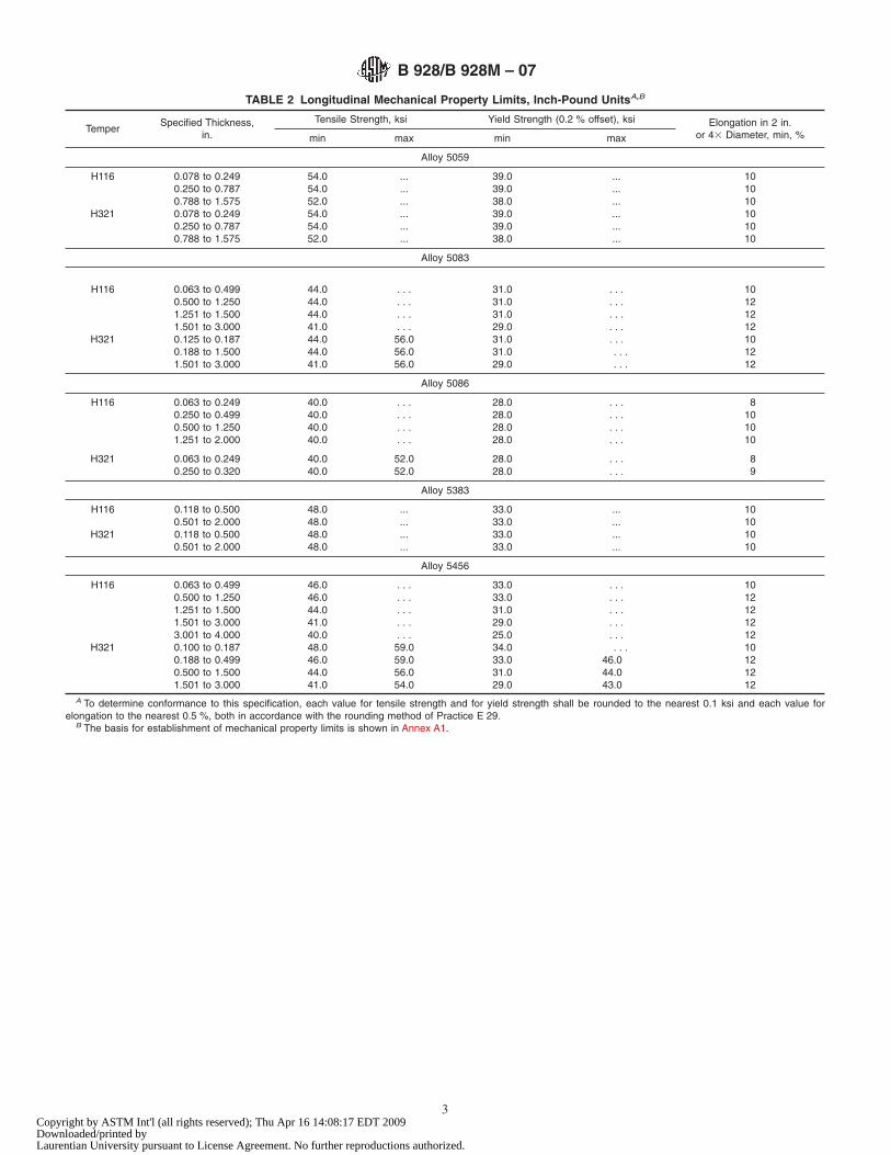
TABLE 2 Longitudinal Mechanical Property Limits, Inch-Pound UnitsA,B
TemperSpecified Thickness,
in.
Tensile Strength, ksi Yield Strength (0.2 % offset), ksi Elongation in 2 in.or 43 Diameter, min, %min max min max
Alloy 5059
H116 0.078 to 0.249 54.0 ... 39.0 ... 100.250 to 0.787 54.0 ... 39.0 ... 100.788 to 1.575 52.0 ... 38.0 ... 10
H321 0.078 to 0.249 54.0 ... 39.0 ... 100.250 to 0.787 54.0 ... 39.0 ... 100.788 to 1.575 52.0 ... 38.0 ... 10
Alloy 5083
H116 0.063 to 0.499 44.0 . . . 31.0 . . . 100.500 to 1.250 44.0 . . . 31.0 . . . 121.251 to 1.500 44.0 . . . 31.0 . . . 121.501 to 3.000 41.0 . . . 29.0 . . . 12
H321 0.125 to 0.187 44.0 56.0 31.0 . . . 100.188 to 1.500 44.0 56.0 31.0 . . . 121.501 to 3.000 41.0 56.0 29.0 . . . 12
Alloy 5086
H116 0.063 to 0.249 40.0 . . . 28.0 . . . 80.250 to 0.499 40.0 . . . 28.0 . . . 100.500 to 1.250 40.0 . . . 28.0 . . . 101.251 to 2.000 40.0 . . . 28.0 . . . 10
H321 0.063 to 0.249 40.0 52.0 28.0 . . . 80.250 to 0.320 40.0 52.0 28.0 . . . 9
Alloy 5383
H116 0.118 to 0.500 48.0 ... 33.0 ... 100.501 to 2.000 48.0 ... 33.0 ... 10
H321 0.118 to 0.500 48.0 ... 33.0 ... 100.501 to 2.000 48.0 ... 33.0 ... 10
Alloy 5456
H116 0.063 to 0.499 46.0 . . . 33.0 . . . 100.500 to 1.250 46.0 . . . 33.0 . . . 121.251 to 1.500 44.0 . . . 31.0 . . . 121.501 to 3.000 41.0 . . . 29.0 . . . 123.001 to 4.000 40.0 . . . 25.0 . . . 12
H321 0.100 to 0.187 48.0 59.0 34.0 . . . 100.188 to 0.499 46.0 59.0 33.0 46.0 120.500 to 1.500 44.0 56.0 31.0 44.0 121.501 to 3.000 41.0 54.0 29.0 43.0 12
A To determine conformance to this specification, each value for tensile strength and for yield strength shall be rounded to the nearest 0.1 ksi and each value forelongation to the nearest 0.5 %, both in accordance with the rounding method of Practice E 29.
B The basis for establishment of mechanical property limits is shown in Annex A1.
B 928/B 928M – 07
3Copyright by ASTM Int'l (all rights reserved); Thu Apr 16 14:08:17 EDT 2009Downloaded/printed byLaurentian University pursuant to License Agreement. No further reproductions authorized.

TABLE 3 Longitudinal Mechanical Property Limits [SI Units]A,B
Temper
Specified Thickness, mm Tensile Strength, MPa Yield Strength (0.2 % offset), MPa Elongation, min, %C
over through min max min max in 50 mmin 53 Diameter
(5.65 =A )
Alloy 5059
H116 1.99 6.30 370 ... 270 ... 10 ...6.30 12.50 370 ... 270 ... 10 ...12.50 20.00 370 ... 270 ... ... 1020.00 40.00 360 ... 260 ... ... 10
H321 1.99 6.30 370 ... 270 ... 10 ...6.30 12.50 370 ... 270 ... 10 ...12.50 20.00 370 ... 270 ... ... 1020.00 40.00 360 ... 260 ... ... 10
Alloy 5083
H116 1.60 12.50 305 . . . 215 . . . 10 . . .12.50 30.00 305 . . . 215 . . . . . . 1030.00 40.00 305 . . . 215 . . . . . . 1040.00 80.00 285 . . . 200 . . . . . . 10
H321 3.20 5.00 305 385 215 . . . 10 . . .5.00 12.50 305 385 215 . . . 12 . . .
12.50 40.00 305 385 215 . . . . . . 1040.00 80.00 285 385 200 . . . . . . 10
Alloy 5086
H116 1.60 6.30 275 . . . 195 . . . 8 . . .6.30 12.50 275 . . . 195 . . . 10 . . .
12.50 30.00 275 . . . 195 . . . . . . 930.00 50.00 275 . . . 195 . . . . . . 9
H321 1.60 6.30 275 355 195 . . . 8 . . .6.30 8.00 275 355 195 . . . 9 . . .
Alloy 5383
H116 3.00 12.50 330 ... 230 ... 10 ...12.50 50.00 330 ... 230 ... ... 10
H321 3.00 12.50 330 ... 230 ... 10 ...12.50 50.00 330 ... 230 ... ... 10
Alloy 5456
H116 1.60 12.50 315 . . . 230 . . . 10 . . .12.50 30.00 315 . . . 230 . . . . . . 1030.00 40.00 305 . . . 215 . . . . . . 1040.00 80.00 285 . . . 200 . . . . . . 1080.00 110.00 275 . . . 170 . . . . . . 10
H321 2.50 4.00 330 405 235 . . . 10 . . .4.00 12.50 315 405 230 315 12 . . .
12.50 40.00 305 385 215 305 . . . 1040.00 80.00 285 370 200 295 . . . 10
A To determine conformance to this specification, each value for tensile strength and for yield strength shall be rounded to the nearest 1 MPa and each value forelongation to the nearest 0.5 %, both in accordance with the rounding method of Practice E 29.
B The basis for establishment of mechanical property limits is shown in Annex A1.C Elongations in 50 mm apply for thicknesses up through 12.50 mm and in 53 diameter (5.65 =A ) for thicknesses over 12.50 mm where A is the cross-sectional area
of the specimen.
TABLE 4 Long Transverse Mechanical Property Limits, Inch-Pound UnitsA,B
TemperSpecified Thickness, in. Tensile Strength, ksi Yield Strength (0.2 % offset), ksi Elongation in 2 in.
or 34 Diameter, min, %min max min max
Alloy 5083
H116 0.118 to 0.249 44.0 . . . 31.0 . . . 100.250 to 0.499 44.0 . . . 31.0 . . . 10
H321 0.118 to 0.236 44.0 55.0 31.0 . . . 10
Alloy 5086
H321 0.250 to 0.320 40.0 52.0 28.0 . . . 10A To determine conformance to this specification, each value for tensile strength and for yield strength shall be rounded to the nearest 0.1 ksi and each value for
elongation to the nearest 0.5 %, both in accordance with the rounding method of Practice E 29.B The basis for establishment of mechanical property limits is shown in Annex A1.
B 928/B 928M – 07
4Copyright by ASTM Int'l (all rights reserved); Thu Apr 16 14:08:17 EDT 2009Downloaded/printed byLaurentian University pursuant to License Agreement. No further reproductions authorized.

7.2.1 When samples are taken at the time the ingots are cast,at least one sample shall be taken for each group of ingots castsimultaneously from the same source of molten metal.
7.2.2 When samples are taken from the finished or semifin-ished product, a sample shall be taken to represent each 4000lb [2000 kg] or fraction thereof, of material in the lot, exceptthat not more than one sample shall be required per piece.
7.3 Methods of Sampling—Samples for determination ofchemical composition shall be taken in accordance with one ofthe following methods:
7.3.1 Samples for chemical analysis shall be taken bydrilling, sawing, milling, turning, or clipping a representativepiece or pieces to obtain a prepared sample of not less than 75g. Sampling shall be in accordance with Practice E 55.
7.3.2 Sampling for spectrochemical analysis shall be inaccordance with Practices E 716. Samples for other methods ofanalysis shall be suitable for the form of material beinganalyzed and the type of analytical method used.
7.4 Methods of Analysis—The determination of chemicalcomposition shall be made in accordance with suitable chemi-cal (Test Methods E 34), or spectrochemical (Test MethodE 1251) methods. Other methods may be used only when nopublished ASTM method is available. In case of dispute, themethods of analysis shall be as agreed upon between theproducer and purchaser.
8. Tensile Properties of Material as Supplied
8.1 Limits—The sheet and plate shall conform to the re-quirements for tensile properties as specified in Table 2 [Table3] or Table 4 [Table 5]. Table 2 [Table 3] includes specificationlimits for tensile properties in the longitudinal direction. Table4 [Table 5] includes specification limits for tensile properties inthe long transverse direction.
8.1.1 Tensile property limits for sizes not covered in Table2 or Table 4 [Table 3 or Table 5] shall be as agreed uponbetween the producer and purchaser and shall be so specified inthe contract or purchase order.
8.2 Number of Samples—One sample shall be taken fromeach end of each parent coil, or parent plate, but no more thanone sample per 2000 lb [1000 kg] of sheet or 4000 lb [2000 kg]of plate, or part thereof, in a lot shall be required. Otherprocedures for selecting samples may be employed if agreedupon between the producer and purchaser.
8.3 Test Specimens—Geometry of test specimens and thelocation in the product from which they are taken shall be asspecified in Test Methods B 557 or B 557M, with the exceptionthat the test direction will be as specified in 8.5.
8.4 Test Methods—The tension test shall be made in accor-dance with Test Methods B 557 or B 557M.
8.5 Testing Direction—Tensile testing shall be in the longi-tudinal direction unless the long transverse direction is speci-fied in the contract or purchase order. Tensile testing directionshall be noted on all documentation.
9. Exfoliation and Intergranular Corrosion Resistance
9.1 Only the Alloy-Tempers shown in Table 2 and Table 4[Table 3 and Table 5] are manufactured and corrosion tested forintended use in marine hull construction or in marine applica-tions where frequent or constant direct contact with seawater isexpected. See Notes 3 and 4. (Warning—It is possible to meetthe requirements of Test Method G 66 (ASSET) and fail therequirements of Test Method G 67 (NAMLT). Therefore bothtests shall be performed for process qualification (see 9.4), forlot release, that is, in developing producer-established refer-ence photomicrographs (see 9.5), and for surveillance (see9.8).)
NOTE 3—Background Information—Aluminum-magnesium-alloyproducts that have a continuous or nearly continuous grain boundaryprecipitate are susceptible to intergranular forms of corrosion, (that is,IGC, SCC, or exfoliation corrosion). Examples of varying degrees of grainboundary precipitate continuity are shown in Figs. 1 and 2. The term“sensitization” is used to describe the development of this susceptiblemicrostructure. The type of corrosion that occurs in a sensitized 5xxx alloywill depend primarily on the morphology of the grain structure and on theresidual and applied stresses that are present. The extent of corrosion thatwill occur depends on the degree of continuity of the grain boundaryprecipitation and the corrosiveness of the environment. Both recrystallizedand unrecrystallized 5xxx alloys that have been sensitized, are susceptibleto intergranular corrosion, and when subjected to sustained tensile stress,may exhibit intergranular stress corrosion cracking. Unrecrystallized 5xxxalloys that have been sensitized are also susceptible to exfoliationcorrosion.
NOTE 4—Alloys 5059, 5083, 5086, 5383, and 5456 should not be usedfor service, which provides prolonged exposure to temperatures exceeding150°F [65°C] (whether continuous exposure or discontinuous exposure)because of the risk of sensitization and the resulting susceptibility to
TABLE 5 Long Transverse Mechanical Property Limits [SI Units]A,B
Temper Specified Thickness, mm Tensile Strength, MPa Yield Strength (0.2 % offset), MPa Elongation, min, %C
over through min max min max in 50 mm in 5x Diameter(5.65 =A )
Alloy 5083
H116 3.00 6.00 305 . . . 215 . . . 10 . . .6.00 12.50 305 . . . 215 . . . 10 . . .
H321 3.00 6.00 305 380 215 . . . 10 . . .
Alloy 5086
H321 6.00 8.00 275 355 195 . . . 10 . . .ATo determine conformance to this specification, each value for tensile strength shall be rounded to the nearest 1 MPa and each value for elongation to the nearest 0.5 %,
both in accordance with the rounding method of Practice E 29.BThe basis for establishment of mechanical property limits is shown in Annex A1.CElongations in 50 mm apply for thicknesses up through 12.50 mm and in 53 diameter (5.65=A) for thicknesses over 12.50 mm where A is the cross-sectional area
of the specimen.
B 928/B 928M – 07
5Copyright by ASTM Int'l (all rights reserved); Thu Apr 16 14:08:17 EDT 2009Downloaded/printed byLaurentian University pursuant to License Agreement. No further reproductions authorized.

intergranular corrosion and stress corrosion cracking. Cold forming canalso increases susceptibility to intergranular corrosion and stress corrosioncracking.
9.2 Exfoliation-Corrosion Resistance—The alloy-temperslisted in Table 2 and Table 4 [Table 3 and Table 5] shall becapable of exhibiting no evidence of exfoliation corrosion anda pitting rating of PB or better when subjected to the testdescribed in Test Method G 66 (ASSET).
9.3 Intergranular-Corrosion Resistance—The alloy-tempers listed in Table 2 and Table 4 [Table 3 and Table 5] shallbe capable of exhibiting resistance to intergranular corrosion asindicated by an acceptable mass-loss when tested in accor-dance with Test Method G 67 (NAMLT). Test Method G 67mass loss results shall be interpreted as defined in 9.3.1 through9.3.4.
9.3.1 Pass—Samples with mass loss no greater than 100mg/in.2 [15 mg/cm2], shall be accepted.
9.3.2 Fail—Samples with mass loss greater than 160 mg/in.2 [25 mg/cm2] and the lots they represent, shall be rejected.
9.3.3 Questionable—Samples with mass loss greater than100 mg/in.2 [15 mg/cm2] but less than 160 mg/in.2 [25 mg/cm2] shall be deemed questionable and shall be subjected tometallographic examination (See 9.3.4).
9.3.4 Examination of Samples Deemed Questionable—Alongitudinal face perpendicular to the rolled surface of TestMethod G 67 corroded test coupons testing “questionable,”shall be prepared (see Fig. 3). The exposed “corroded” surfaceof this sample shall be examined metallographically in theas-polished condition to determine if the loss of mass was a
Specimens prepared as per 9.6.1 (Phosphoric Acid etched). (This is as-produced material, not subjected to Test Method G 67 testing.) Metallographic examination isto be conducted 3500 magnification.
Figure 1a has discontinuous grain boundary precipitation, typical of a mass-loss of less than 15 mg/cm2 in Test Method G 67.Figure 1b has semi-continuous grain boundary precipitation and would likely fall in the mid-range, 15–25 mg/cm2 in Test Method G 67.Figure 1c has a continous network of grain boundary precipitation, typical of a mass loss greater than 25 mg/cm2 in Test Method G 67.(Warning—These photomicrographs are examples of typical microstructures and due to variations in alloy, temper and process, they may or may not be similar to the
microstructure of production sheet or plate. These photographs shall not be used in lieu of producer-established reference photographs for comparison with productionmaterial in surveillance or in determining process qualification or lot release.)
FIG. 1 Examples of Microstructures with Varied Degrees of Grain Boundary Beta-phase Continuity, for a Partially Recrystallized GrainStructure.
B 928/B 928M – 07
6Copyright by ASTM Int'l (all rights reserved); Thu Apr 16 14:08:17 EDT 2009Downloaded/printed byLaurentian University pursuant to License Agreement. No further reproductions authorized.

result of intergranular attack or general corrosion and pittingattack (see examples shown in Fig. 4). When preparing thepolished metallographic sample, a rough-grinding step thatremoves at least 0.02 in. [0.5 mm] of metal should precede thefinal polishing step. A magnification of 3250 is recommended.
9.3.4.1 Pass—Samples exhibiting general or pitting attackwith no intergranular attack shall be accepted.
9.3.4.2 Fail—Samples exhibiting intergranular attack andthe lots they represent, shall be rejected.
9.4 Process Qualification (see 9.1)—For material producedto this specification, the producer’s production process shall bequalified prior to production to this specification, by sampling
and testing material to establish the relationship betweenmicrostructure and resistance to corrosion.
9.4.1 A reference photomicrograph, taken at 3500 after 3minutes etch in 40 % phosphoric acid @ 95°F [35°C] (See9.6.1), shall be established for each of the alloy-tempers andthickness ranges shown in Table 2 and Table 4 [Table 3 andTable 5], and shall be taken from a sample within that thicknessrange.
9.4.1.1 The reference photomicrographs shall be taken fromsamples (see 9.5 and 9.6 for sample location and preparation)which exhibit no evidence of exfoliation corrosion and a pitting
Specimens prepared as per 9.6.1 (Phosphoric Acid etched). (This is as-produced material, not subjected to G 67 testing.) Metallographic examination is to be conducted3500 magnification.
Figure 2a has discontinuous grain boundary precipitation, typical of a mass-loss of less than 15 mg/cm2 in Test Method G 67.Figure 2b has semi-continuous grain boundary precipitation and would likely fall in the mid-range, 15 – 25 mg/cm2 in Test Method G 67.Figure 2c has a continuous network of grain boundary precipitation, typical of a mass loss greater than 25 mg/cm2 in Test Method G 67.(Warning—These photomicrographs are examples of typical microstructures and due to variations in alloy, temper and process, they may or may not be similar to the
microstructure of production sheet or plate. These photographs shall not be used in lieu of producer-established reference photographs for comparison with productionmaterial in surveillance or in determining process qualification or lot release.)
FIG. 2 Examples of Microstructures with Varied Degrees of Grain Boundary Beta-phase Continuity, for a Fully Un-recrystallized GrainStructure.
B 928/B 928M – 07
7Copyright by ASTM Int'l (all rights reserved); Thu Apr 16 14:08:17 EDT 2009Downloaded/printed byLaurentian University pursuant to License Agreement. No further reproductions authorized.

rating of PB or better when subjected to the test described inTest Method G 66 (ASSET).
9.4.1.2 The samples from which the reference photomicro-graphs are taken shall also exhibit resistance to intergranularcorrosion at a mass loss no greater than 100 mg/in.2 (15mg/cm2), when subjected to the test described in Test MethodG 67 (NAMLT).
9.4.2 Production practices shall not be changed after estab-lishment of the reference photomicrograph except as providedin 9.8.
9.4.3 The producer shall maintain, at the producing facility,all records relating to the establishment of reference photomi-crographs and production practices.
9.5 Lot Release (see Note 4)—At the option of the producer,the acceptability of each lot of material shall be determined byeither testing each lot to the requirements of 9.2 and 9.3, or bymetallographic examination. In either option, one sample perlot shall be selected at mid width from one end of a random coilor random sheet or plate and tested or examined.
9.6 Metallographic Examination—If this option is used, themicrostructure of a sample from each production lot shall becompared to that of the producer-established reference photo-micrograph of acceptable material, in the same thickness range,(see 9.4).
9.6.1 A longitudinal section perpendicular to the rolledsurface shall be prepared for metallographic examination (seeFig. 5) and shall be microetched for metallographic examina-tion using 40 % phosphoric acid etch for 3 minutes at 95°F[35°C]. The metallographic examination shall be conducted at3500 magnification.
9.6.2 The reference microstructure is characterized by beingpredominantly free of a continuous grain boundary network ofaluminum-magnesium (Mg2Al3) precipitate.
9.6.3 If the microstructure shows evidence of a continuousgrain boundary network of aluminum-magnesium precipitatein excess of the producer-established reference photomicro-graphs of acceptable material (developed as described in 9.4),
the lot is either rejected or tested for exfoliation-corrosionresistance and intergranular corrosion resistance in accordancewith 9.2 and 9.3.
9.7 Sampling for Corrosion Testing—Samples for Exfolia-tion Corrosion Resistance Testing and Intergranular CorrosionTesting should be selected in the same manner specified for lotrelease (see 9.5) and shall be taken from the same sheet or plateused for the metallographic test (see 9.6).
9.7.1 Exfoliation corrosion testing specimens prepared fromthe sample shall be full section thickness, except that formaterial 0.101 in. [2.50 mm] or more in thickness, 10 % of thethickness shall be removed, by machining, from one as-rolledsurface. Both the machined surface and the remaining as-rolledsurface shall be evaluated after exposure per Test MethodG 66.
9.7.2 Intergranular corrosion testing specimens preparedfrom the sample shall be full section thickness, except thatmaterial 1.0 in [25 mm] or more in thickness is to be reducedby one half the thickness or by 1 in. [25 mm], whichever is lesswhile retaining one original as-fabricated surface in accordancewith test specimen fabrication procedures outlined in TestMethod G 67.
9.8 Surveillance (see Note 4)—Each quarter, and after anysignificant process change, the producer shall perform at leastone test for exfoliation corrosion and one test for intergranularcorrosion in accordance with 9.2 and 9.3 for each alloy andthickness range of the materials in Table 2 and Table 4 [Table3 and Table 5] produced that quarter. Test Methods G 66 andG 67 samples shall be taken at random according to 9.5 andprepared according to 9.7.1 and 9.7.2. The producer shallmaintain records of each lot so tested and make them availablefor examination at the producer’s facility.
10. Dimensional Tolerances
10.1 Thickness—The thickness of flat sheet, coiled sheet,and plate shall not vary from that specified, by more than the
FIG. 3 Longitudinal Section of the Corroded G 67 Sample, Showing Rolling Direction, Plane to be Polished, and Surface to beMetallographically Examined for Evidence of Intergranular Corrosion.
B 928/B 928M – 07
8Copyright by ASTM Int'l (all rights reserved); Thu Apr 16 14:08:17 EDT 2009Downloaded/printed byLaurentian University pursuant to License Agreement. No further reproductions authorized.

respective permissible variations prescribed in Tables 7.7a ofANSI H35.2 [H35.2M].
10.2 Length, Width, Lateral Bow, Squareness, andFlatness—Coiled sheet shall not vary in width or in lateral bowfrom that specified by more than the permissible variationsprescribed in Tables 7.11 and Tables 7.12, respectively, ofANSI H35.2 [H35.2M]. Flat sheet and plate shall not vary inwidth, length, lateral bow, squareness, or flatness by more thanthe permissible variations prescribed in the following tables ofANSI H35.2 [H35.2M], except that where the tolerances forsizes ordered are not covered by this standard, the permissiblevariations shall be the subject of agreement between thepurchaser and the producer, or the supplier and the purchaser,at the time the order is placed:
ANSI H 35.2 andANSI H 35.2MTable Numbers
Title
7.8 Width Tolerances—Sheared Flat Sheet and Plate7.9 Length Tolerances—Sheared Flat Sheet and Plate7.10 Width and Length Tolerances—Sawed Flat Sheet and Plate7.11 Width Tolerances—Slit Coiled Sheet7.12 Lateral Bow Tolerances—Coiled Sheet7.13 Lateral Bow Tolerances—Flat Sheet and Plate7.14 Squareness Tolerances—Flat Sheet and Plate7.17 Flatness Tolerances—Flat Sheet7.18 Flatness Tolerances—Sawed or Sheared Plate
10.3 Dimensional tolerances for sizes not covered in ANSIH35.2 [H35.2M] shall be as agreed upon between the producerand purchaser or between the supplier and purchaser and shallbe so specified in the contract or purchase order.
The recommended magnification is 3250.Figures 4a and 4b are examples of general corrosion and pitting attack. These samples are examples of material that would pass Specification B 928/B928M per 9.3.4.Figures 4c and 4d are examples of an intergranular attack and are examples of material that would fail Specification B 928/B928M per 9.3.4. Figure 4c illustrates an
example of an unrecrystallized microstructure, and Fig. 4d is an example of a partially recrystallized microstructure.
FIG. 4 Examples of the corrosion morphology produced by Test Method G 67, for varying degrees of sensitization, from pitting andgeneral corrosion to intergranular corrosion. Metallography is in the as-polished condition.
B 928/B 928M – 07
9Copyright by ASTM Int'l (all rights reserved); Thu Apr 16 14:08:17 EDT 2009Downloaded/printed byLaurentian University pursuant to License Agreement. No further reproductions authorized.

10.4 Sampling for Inspection—Examination for dimen-sional conformance shall be made to ensure conformance to thetolerance specified.
11. Source Inspection
11.1 If the purchaser desires that his representative inspector witness the inspection and testing of the material prior toshipment, such agreement shall be made by the purchaser andproducer as part of the purchase contract.
11.2 When such inspection or witness of inspection andtesting is agreed upon, the producer shall afford the purchaser’srepresentative all reasonable facilities to satisfy him that thematerial meets the requirements of this specification. Inspec-tion and tests shall be conducted so there is no unnecessaryinterference with the producer’s operations.
12. Retest and Rejection
12.1 If any material fails to conform to all of the applicablerequirements of this specification, the inspection lot shall berejected.
12.2 When there is evidence that a failed specimen was notrepresentative of the inspection lot and when no other samplingplan is provided or approved by the purchaser through thecontract or purchase order, at least two additional specimensshall be selected to replace each test specimen that failed. Allspecimens so selected for retest shall meet the requirements ofthe specification or the lot shall be subject to rejection.
12.3 Material in which nonconforming conditions are dis-covered subsequent to inspection may be rejected at the optionof the purchaser.
12.4 The producer or supplier is responsible only for mate-rial replacement, when the purchaser rejects material. As muchas possible of the rejected material shall be returned to theproducer or supplier by the purchaser.
13. Certification
13.1 The producer or supplier shall, on request, furnish tothe purchaser a certificate stating that each lot has beensampled, tested, and inspected in accordance with this speci-fication, and has met the requirements.
14. Identification Marking of Product
14.1 All sheet and plate shall be marked by the producer inaccordance with Practice B 666/B 666M. When product issupplied to the distributor in coil form, the distributor shallmark cut-to-length sheet in accordance with B 666/B 666M.
14.2 The requirements specified in 14.1 are minimum;marking systems that involve added information, larger char-acters, and greater frequencies are acceptable under thisspecification.
15. Packaging and Package Marking
15.1 The material shall be packaged to provide adequateprotection during normal handling and transportation, and eachpackage shall contain only one size, alloy, and temper ofmaterial unless otherwise agreed. The type of packaging andgross weight of containers shall, unless otherwise agreed, be atthe producer’s or supplier’s discretion, provided that they aresuch as to ensure acceptance by common or other carriers forsafe transportation at the most cost effective rate to the deliverypoint.
15.2 Each shipping container shall be marked with thepurchase order number, material size, specification number,alloy and temper, gross and net weights, and the producer’sname or trademark.
15.3 When specified in the contract or purchase order,material shall be preserved, packaged, and packed in accor-dance with the requirements of Practices B 660. The applicablelevels shall be as specified in the contract or order.
FIG. 5 Longitudinal Section Cut from Product, Showing Rolling Direction and Plane to be Metallographically Prepared for Making aReference Photomicrograph (see 9.4.1) and Metallographic Lot Release Testing (see 9.6).
B 928/B 928M – 07
10Copyright by ASTM Int'l (all rights reserved); Thu Apr 16 14:08:17 EDT 2009Downloaded/printed byLaurentian University pursuant to License Agreement. No further reproductions authorized.

16. Keywords16.1 aluminum alloy; aluminum-alloy plate; aluminum-
alloy sheet; marine application; marine grade
ANNEXES
(Mandatory Information)
A1. BASIS FOR INCLUSION OF PROPERTY LIMITS
A1.1 Limits are established at a level at which a statisticalevaluation of the data indicates that 99 % of the populationobtained from all standard material meets the limit with 95 %confidence. For the products described, mechanical propertylimits for the respective size ranges are based on the analysesof at least 100 data from standard production material with no
more than ten data from a given lot. All tests are performed inaccordance with the appropriate ASTM test methods. Forinformational purposes, refer to “Statistical Aspects of Me-chanical Property Assurance” in the Related Material section ofthe Annual Book of ASTM Standards, Vol 02.02.
A2. ACCEPTANCE CRITERIA FOR INCLUSION OF NEW ALUMINUM AND ALUMINUM ALLOYSIN THIS SPECIFICATION
A2.1 Prior to acceptance for inclusion in this specification,the composition of wrought or cast aluminum or aluminumalloy shall be registered in accordance with ANSI H35.1/H35.1(M). The Aluminum Association3 holds the Secretariat ofANSI H35 Committee and administers the criteria and proce-dures for registration.
A2.2 If it is documented that the Aluminum Associationcould not or would not register a given composition, analternative procedure and the criteria for acceptance shall be asfollows:
A2.2.1 The designation submitted for inclusion does notutilize the same designation system as described in ANSIH35.1/H35.1(M). A designation not in conflict with otherdesignation systems or a trade name is acceptable.
A2.2.2 The aluminum or aluminum alloy has been offeredfor sale in commercial quantities within the prior twelvemonths to at least three identifiable users.
A2.2.3 The complete chemical composition limits are sub-mitted.
A2.2.4 The composition is, in the judgment of the respon-sible subcommittee, significantly different from that of anyother aluminum or aluminum alloy already in the specification.
A2.2.5 For codification purposes, an alloying element is anyelement intentionally added for any purpose other than grainrefinement and for which minimum and maximum limits arespecified. Unalloyed aluminum contains a minimum of99.00 % aluminum.
A2.2.6 Standard limits for alloying elements and impuritiesare expressed to the following decimal places:
Less than 0.001 % 0.000X0.001 to but less than 0.01 % 0.00X0.01 to but less than 0.10 %
Unalloyed aluminum made by arefining process 0.0XXAlloys and unalloyed aluminum notmade by a refining process 0.0X
0.10 through 0.55 %(It is customary to express limits of0.30 through 0.55 % as 0.X0 or 0.X5.)
0.XX
Over 0.55 % 0.X, X.X, and so forth.(except that combined Si + Fe limitsfor 99.00 % minimum aluminummust be expressed as 0.XX or 1.XX)
A2.2.7 Standard limits for alloying elements and impuritiesare expressed in the following sequence: Silicon; Iron; Copper;Manganese; Magnesium; Chromium; Nickel; Zinc; Titanium(see Note A2.1); Other Elements, Each; Other Elements, Total;Aluminum (Note A2.2).
NOTE A2.1—Additional specified elements having limits are inserted inalphabetical order of their chemical symbols between Titanium and otherelements, each, or are specified in footnotes.
NOTE A2.2—Aluminum is specified as minimum for unalloyed alumi-num and as a remainder for aluminum alloys.
B 928/B 928M – 07
11Copyright by ASTM Int'l (all rights reserved); Thu Apr 16 14:08:17 EDT 2009Downloaded/printed byLaurentian University pursuant to License Agreement. No further reproductions authorized.

SUMMARY OF CHANGES
Committee B07 has identified the location of selected changes to this standard since the last issue (B 928 – 03)that may impact the use of this standard. (Approved May 15, 2007.)
(1) Deleted phrase in 9.6.1 allowing the use of an alternativeetch for the production of reference photomicrographs anddeleted the referenced ASTM standard from the list of Refer-enced Documents in Section 2.(2) Deleted ANSI H35.1(M) in Section 2 and replaced ANSIH35.1 with H35.1/H35.1(M).(3) Section 4.2.4 and 8. Added words to allow harmonizationof this specification with existing American and Europeanspecifications by allowing for tensile testing in the longtransverse direction when called for by the purchaser.(4) Notes 3 and 4 were renumbered and reordered.(5) Added “continuity” to grain boundary precipitate in Note 3.(6) Added Fig. 2 for illustration in Note 3.(7) Revised sentence to include “Both recrystallized” 5xxxalloys in Note 3.(8) Revised sentence to include “also” susceptible to exfolia-tion corrosion in Note 3.(9) Revised sentence to include “cold forming can alsoincrease” in Note 4.(10) Rewrote 9.3 to clarify the use and interpretation of TestMethod G 67(11) Revised 9.3.4 to clarify the use and interpretation of TestMethod G 67(12) Changed photographs to “photomicrograph” in 9.4.1.1.(13) In 9.6.1, replaced reference to Symbol E in Fig. 1 ofPractice E 3 with Fig. 5.(14) Added Table 4 and Table 5 to provide long transversetensile properties. References to mechanical property tableswere accordingly renumbered throughout specification.(15) Table 2: deleted maximum yield strengths for 5083-H321.(16) Table 2: added 5086-H321 longitudinal properties in
thickness ranges 0.063 to 0.249 and 0.250 to 0.320 in.(17) Table 2: added 5456-H321 longitudinal properties inthickness range 0.100 to 0.187 in.(18) Table 3: deleted Max. Yields Strenth for 5083-H321.(19) Table 3: added 5086-H321 longitudinal properties inthickness ranges 1.60 to 6.30 and 6.00 to 8.00 mm.(20) Table 3: 5383-H116 and 5383-H321 changed thicknessesfrom 50.80 to 50.00 mm and 12.70 to 12.50 mm.(21) Table 3: deleted entries for elongation in the 5x Diametercolumn for 5383-H116 thickness range 3.00 to 12.50 and5383-H321 thickness range 3.00 to 12.50.(22) Table 3: Added 5456-H321 longitudinal properties inthickness range 2.50 to 4.00 mm.(23) Replaced Figure 1 with new Figs. 1 and 2. Replaced Fig.2 with new Fig. 4. These figures provide better and morecomplete illustrations.(24) Added Fig. 3 to clarify sampling location.(25) Replaced Fig. 3 with Fig. 5 to clarify sampling location.(26) Editorial changes to A2.2.7 and Note A2.1 to reflectwording in Aluminum Association, Inc. Teal Sheets.(27) Corrected address for Aluminum Association, Inc.(28) Table 3: 5086–H321 changed the thickness from 6.00 to6.30.(29) Deleted reference to ASTM Methods E 407 and E 607.(30) IC was changed to IGC in Note 3.(31) Section 9.3.3 changed to “deemed” questionable “andshall be subjected to metallographic examination (See 9.3.4).(32) Section 9.3.2 added “and the lots they represent.”(33) For clarity, added “after 3 minutes etch in 40 % phospho-ric acid @95°F [35°C] (See 9.6.1)” to 9.4.1.
ASTM International takes no position respecting the validity of any patent rights asserted in connection with any item mentionedin this standard. Users of this standard are expressly advised that determination of the validity of any such patent rights, and the riskof infringement of such rights, are entirely their own responsibility.
This standard is subject to revision at any time by the responsible technical committee and must be reviewed every five years andif not revised, either reapproved or withdrawn. Your comments are invited either for revision of this standard or for additional standardsand should be addressed to ASTM International Headquarters. Your comments will receive careful consideration at a meeting of theresponsible technical committee, which you may attend. If you feel that your comments have not received a fair hearing you shouldmake your views known to the ASTM Committee on Standards, at the address shown below.
This standard is copyrighted by ASTM International, 100 Barr Harbor Drive, PO Box C700, West Conshohocken, PA 19428-2959,United States. Individual reprints (single or multiple copies) of this standard may be obtained by contacting ASTM at the aboveaddress or at 610-832-9585 (phone), 610-832-9555 (fax), or [email protected] (e-mail); or through the ASTM website(www.astm.org).
B 928/B 928M – 07
12Copyright by ASTM Int'l (all rights reserved); Thu Apr 16 14:08:17 EDT 2009Downloaded/printed byLaurentian University pursuant to License Agreement. No further reproductions authorized.
Copyright © 2022 FDOKUMEN