Effect of the blank holder force on drawing of aluminum alloy square cup: Theoretical and...
9
journal of materials processing technology 206 ( 2 0 0 8 ) 152–160 journal homepage: www.elsevier.com/locate/jmatprotec Effect of the blank holder force on drawing of aluminum alloy square cup: Theoretical and experimental investigation Halil. ˙ Ibrahim Demirci 1 , Cemal Esner, Mustafa Yasar ∗ Karabuk University, Technical Education Faculty, Turkiye article info Article history: Received 29 August 2007 Received in revised form 31 October 2007 Accepted 4 December 2007 Keywords: Square deep drawing Finite element analyze AA5754-O Earings abstract In this study, the influence of AA5754-O material, an aluminum alloy, in forming the blank holder force (BHF) in deep drawing process has been investigated. For this purpose, a new experimental system has been prepared. By means of this system, deep drawing process can be implemented through applying variable forces in computer-controlled manner on the blank holder and sheet plate. The numerical model of forming with deep drawing process has been built up and analyzed via the LS-DYNA software. Cup depths, tearing and wall thickness variations of the experimental and numerical results have been compared. It has been observed that no earing and wrinkling have occurred in BHF’s between 1.3 and 8 MPa in square deep drawing process, and that tears have occurred in forces exceeding 18 MPa. It has further been observed that the best forming has occurred at 5 MPa, and that the numerical and experimental model developed is in harmony with one another at a rate of 85%. © 2007 Elsevier B.V. All rights reserved. 1. Introduction As thin-walled cups are intensively employed in the indus- try, plastic deformation by means of deep drawing process has been investigated by myriad of researchers. Majority of the surveys have concentrated on the limit drawing ratio (LDR) in plastic deformation or problems occurring during the deep drawing process such as folding, wrinkling and tearing. Folding and tearing problems in deep drawing process may depend on several effects, in addition to the BHF. These are; the clearance between the matrix and the punch, rate of rounding the matrix edges, rate of rounding the punch edges, lubricity between the matrix of the plate drawn and the punch, draw- ing speed and drawing force. All of these parameters have been investigated by various researchers (Mamalis et al., 1996; Browne and Hillery, 2003; Chen et al., 2003). Deviation of any of the above-mentioned parameters under optimum efficiency ∗ Corresponding author. Tel.: +90 370 433 82 00; fax: +90 370 433 82 04. E-mail addresses: [email protected] (Halil. ˙ I. Demirci), [email protected] (M. Yasar). 1 Tel.: +90 370 433 82 00; fax: +90 370 433 82 04. conditions closely relates to the sensitivity in deep drawing process and the volume of deep drawing. When the above parameters are determined by the method of trial and error, increase in time and cost occurs. There- fore, practically obtaining the values pertaining to the material to be processed will provide advantages in manufacturing and production costs. Currently many researches are car- ried out on this subject (Manabe et al., 2002; Karali, 2005; Gavas, 2005; Gavas and ˙ Izciler, 2006). There is focus particu- larly on studies regarding the decrease of earing on aluminum and magnesium alloys and regarding its effect on the sur- face structure (Tikhovskiy et al., 2007; Walde and Riedel, 2007). Aluminum material of AA5754-O (Turkish grade (Etial 53)) series with a sheet thickness of 2 mm that is highly employed in deep drawing processes has been used in this study for determining BHF and deep drawing process results compared with experimental and numerical. 0924-0136/$ – see front matter © 2007 Elsevier B.V. All rights reserved. doi:10.1016/j.jmatprotec.2007.12.010
Transcript of Effect of the blank holder force on drawing of aluminum alloy square cup: Theoretical and...

j o u r n a l o f m a t e r i a l s p r o c e s s i n g t e c h n o l o g y 2 0 6 ( 2 0 0 8 ) 152–160
journa l homepage: www.e lsev ier .com/ locate / jmatprotec
Effect of the blank holder force on drawing of aluminumalloy square cup: Theoretical and experimental investigation
Halil. Ibrahim Demirci1, Cemal Esner, Mustafa Yasar ∗
Karabuk University, Technical Education Faculty, Turkiye
a r t i c l e i n f o
Article history:
Received 29 August 2007
Received in revised form
31 October 2007
Accepted 4 December 2007
a b s t r a c t
In this study, the influence of AA5754-O material, an aluminum alloy, in forming the blank
holder force (BHF) in deep drawing process has been investigated. For this purpose, a new
experimental system has been prepared. By means of this system, deep drawing process can
be implemented through applying variable forces in computer-controlled manner on the
blank holder and sheet plate. The numerical model of forming with deep drawing process
has been built up and analyzed via the LS-DYNA software. Cup depths, tearing and wall
thickness variations of the experimental and numerical results have been compared. It has
Keywords:
Square deep drawing
Finite element analyze
AA5754-O
been observed that no earing and wrinkling have occurred in BHF’s between 1.3 and 8 MPa in
square deep drawing process, and that tears have occurred in forces exceeding 18 MPa. It has
further been observed that the best forming has occurred at 5 MPa, and that the numerical
and experimental model developed is in harmony with one another at a rate of 85%.
series with a sheet thickness of 2 mm that is highly employed
Earings
1. Introduction
As thin-walled cups are intensively employed in the indus-try, plastic deformation by means of deep drawing processhas been investigated by myriad of researchers. Majority ofthe surveys have concentrated on the limit drawing ratio(LDR) in plastic deformation or problems occurring duringthe deep drawing process such as folding, wrinkling andtearing.
Folding and tearing problems in deep drawing process maydepend on several effects, in addition to the BHF. These are; theclearance between the matrix and the punch, rate of roundingthe matrix edges, rate of rounding the punch edges, lubricitybetween the matrix of the plate drawn and the punch, draw-ing speed and drawing force. All of these parameters have
been investigated by various researchers (Mamalis et al., 1996;Browne and Hillery, 2003; Chen et al., 2003). Deviation of any ofthe above-mentioned parameters under optimum efficiency∗ Corresponding author. Tel.: +90 370 433 82 00; fax: +90 370 433 82 04.E-mail addresses: [email protected] (Halil.I. Demirci), my
1 Tel.: +90 370 433 82 00; fax: +90 370 433 82 04.0924-0136/$ – see front matter © 2007 Elsevier B.V. All rights reserved.doi:10.1016/j.jmatprotec.2007.12.010
© 2007 Elsevier B.V. All rights reserved.
conditions closely relates to the sensitivity in deep drawingprocess and the volume of deep drawing.
When the above parameters are determined by the methodof trial and error, increase in time and cost occurs. There-fore, practically obtaining the values pertaining to the materialto be processed will provide advantages in manufacturingand production costs. Currently many researches are car-ried out on this subject (Manabe et al., 2002; Karali, 2005;Gavas, 2005; Gavas and Izciler, 2006). There is focus particu-larly on studies regarding the decrease of earing on aluminumand magnesium alloys and regarding its effect on the sur-face structure (Tikhovskiy et al., 2007; Walde and Riedel,2007).
Aluminum material of AA5754-O (Turkish grade (Etial 53))
[email protected] (M. Yasar).
in deep drawing processes has been used in this study fordetermining BHF and deep drawing process results comparedwith experimental and numerical.

t e c h n o l o g y 2 0 6 ( 2 0 0 8 ) 152–160 153
iBd
2
2
Thea
2
SftbDs
2
Es
Fig. 2 – Dimensions and thicknesses of the square holder.
Table 1 – Chemical composition of AA5754-O alloy (wt.%)
j o u r n a l o f m a t e r i a l s p r o c e s s i n g
A blank holder system is developed with computer controln accordance with the control of the BHF, and the optimumHF for the formability of the material using this system isetermined experimentally and theoretically.
. Experimental studies
.1. Experiment setup
he experiment setup has been provided in Fig. 1. Theydraulic press has a 60 tonnes force. Hydraulic cylindersmployed for controlling the BHF have a diameter of 60 mmnd they are computer operated.
.2. Mold design
ince the purpose of the study is to examine the change onormation and the wall thickness by controlling the BHF ando determine the optimum BHF, the sheet metal thickness haseen selected as 2 mm to minimize the measuring sensitivity.imensions and thicknesses of the square cup to be drawn arehown in Fig. 2.
.3. Chemical composition of material
tial-53 employed in this study is of (AA5754-O, DIN AlMg3)tandards. Al–Mg is an unhardenable alloy and contains
Fig. 1 – Computer operated deep dr
Alloy Mg Si Cu Fe Mn Cr Ti Al
AA5754-O 2.6–3.6 ≤0.4 ≤0.1 ≤0.4 ≤0.5 ≤0.3 ≤0.1 Balance
0.6–7% of Mg and 0.2–0.6% of the other alloys. Its corrosionresistance to seawater is high. It is employed in various fieldsdepending on the Mg rate. Al–Mg mechanical properties aresimilar to pure aluminum. In case Mg rate exceeds 5%, welding
and processing it becomes more difficult. It suffers corrosiondue to tension and has a very excellent capability of makinganodic oxidations (Gurleyik, 1977). Chemical composition ofAA5754-O aluminum alloy is shown in Table 1.awing machine (Karali, 2005).

154 j o u r n a l o f m a t e r i a l s p r o c e s s i n g t e c h n o l o g y 2 0 6 ( 2 0 0 8 ) 152–160
◦
Fig. 3 – Cups formed with different BHF’s are shown.
3. Deep drawing experiments
In order to investigate the variations in the wall thicknessesof square cups, several experiments were carried out throughgradually increasing the BHF at grades of 0.5 MPa. In formingat each grade, thickness distributions and unit elongations ofpieces formed have separately been investigated. In Fig. 3, cupsformed with different BHF’s are shown. All the deep drawingoperations were carried out in one step at 2.1 m/min drawingspeed under a fixed force.
3.1. Investigation of wall thickness
In this study, the influences of the BHF on wall thick-ness during deep drawing of the aluminum alloy AA5754-Osheet material has been investigated through (Finite Element
Method (FEM)) simulation setup and the experiments carriedout.Sheets formed to examine the thickness changes after thedeep drawing experiments are cut in 0◦ and 45◦ directions
Fig. 5 – Thickness chan
Fig. 4 – Thickness change direction of 0 .
and their sides are trimmed. Later the changes of thicknesswere measured in 2 mm ranges by using an optical microm-eter. The thickness changes from the center towards the sidethroughout the diagonal in the 0◦ and 45◦ directions are givengraphically in Figs. 4 and 5, respectively. As is shown fromthese figures, wall thickness varies especially in the corners.With extensive thinning in the intersection particularly withthe increase of the force of the blank holder in the 45◦ direc-tion, the blank holder shows the effect of its force on the wallthickness more clearly. The increase of wrinkles on low BHF’sshows that the ideal pressure force for this material is with inthe 5–8 MPa ranges.
3.2. Determining wrinkling and tearing limits of sheet
In the experiment, excessive wrinkles have been observed forBHF’s equal to and less than 1.3 MPa and tears have broken outat BHF’s exceeding 18 MPa.
To provide a deeper depth, smoother surface and moresmoothly distributed wall thickness for the cup drawn, thedeep drawing deformation of the material drawn has been
investigated and BHF’s determining the tearing and wrinklinglimits for such material have been determined (Haar, 1996;Kırlı, 2003).ge direction of 45◦.

j o u r n a l o f m a t e r i a l s p r o c e s s i n g t e c h n o l o g y 2 0 6 ( 2 0 0 8 ) 152–160 155
Table 2 – Result of the deep drawing processes performed with various BHF’s
a 8 MPa 10 MPa 16 MPa
38 38.5 39.2
3
CisibIirafa
wpctt
eieb1bm8
4
Tfcp
BHF 1 MPa 4 MP
Square cup depths (mm) 36.5 37.3
.3. Influence of BHF on mouth structure
onsidering the fact that the material employed in the studys anisotropic, formation of particular earings in the mouthection due to the unbalance arising in load distribution dur-ng the release of plates deep drawn at high BHF’s from thelank holder plate is an anticipated result (Mattiasson, 2000).n drawing section, experiments were carried out throughmparting low and high amounts of BHF’s, and two of theesults obtained are compared in Fig. 3. As shown in the figure,t high BHF’s such as 15 MPa, an extreme earing occurs due toriction as the sheet plate is compressed between the matrixnd the blank holder plate.
In Table 2, results of the deep drawing processes performedith various BHF’s ranging between 1 and 16 MPa are com-ared. Although the BHF of 16 MPa seems advantageous forup depth; the material consumed for the necessary correc-ion at the mouth, time, energy, labor costs and extremehinning in wall thickness appear as disadvantages.
In order to investigate the earings that are formed theffects of BHF at 10 and 16 MPa the theoretical and exper-mental results are given in Fig. 6. When the earings inxperimental and theoretical outcomes are compared, it cane seen that the results are closer and more compatible at0 MPa, and that at 16 MPa the earings increase, and the gapetween the experimental and theoretical results becomeore obvious. Minimum earings are observed between 5 andMPa.
. Numerical modeling
he LS-DYNA is one of the competent FE analysis codes usedor the computer aided analysis of sheet metal forming pro-esses in the industry, and therefore, the comparison of theredicted formability and process parameters with the finite
Fig. 7 – Numerical model
Fig. 6 – Theoretical and experimental earing result of 10and 16 MPa BHF.
element analyses using the different shell element types avail-able in this code is a representative performance assessmentof the shell element formulations in the stamping processsimulations. In the LS-DYNA simulation environment the shellelement formulations that can be used in the deformationmodeling of the sheet metal blank (Hallquist, 2001).
So as to investigate how much BHF is necessary for the deepdrawing process of the AA5754-O material employed in thisstudy, forces ranging between 0 and 25 MPa were applied in theLS-DYNA program and the numerical analysis of the experi-mental study was affected. The mold, sheet metal and blankholder plate employed in the experimental study was drawnin 1:1 scale through the Graphic Interface Unit (GUI) of the LS-DYNA program for the numerical model (Fig. 7). A blank holder
plate of same dimensions as in the experiment system hasbeen designed and no drawing bearing was used. Rather meshwas woven in sections where deformation is high whereas sec-tions experiencing rather low deformation were divided intoby using LS-DYNA.
156 j o u r n a l o f m a t e r i a l s p r o c e s s i n g t
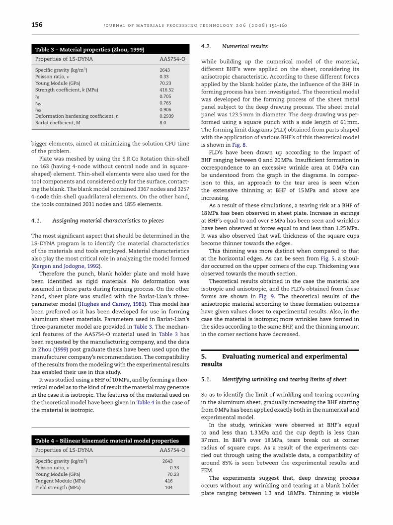
Table 3 – Material properties (Zhou, 1999)
Properties of LS-DYNA AA5754-O
Specific gravity (kg/m3) 2643Poisson ratio, � 0.33Young Module (GPa) 70.23Strength coefficient, k (MPa) 416.52r0 0.705r45 0.765r 0.906
90Deformation hardening coefficient, n 0.2939Barlat coefficient, M 8.0
bigger elements, aimed at minimizing the solution CPU timeof the problem.
Plate was meshed by using the S.R.Co Rotation thin-shellno 163 (having 4-node without central node and in square-shaped) element. Thin-shell elements were also used for thetool components and considered only for the surface, contact-ing the blank. The blank model contained 3367 nodes and 32574-node thin-shell quadrilateral elements. On the other hand,the tools contained 2031 nodes and 1855 elements.
4.1. Assigning material characteristics to pieces
The most significant aspect that should be determined in theLS-DYNA program is to identify the material characteristicsof the materials and tools employed. Material characteristicsalso play the most critical role in analyzing the model formed(Kergen and Jodogne, 1992).
Therefore the punch, blank holder plate and mold havebeen identified as rigid materials. No deformation wasassumed in these parts during forming process. On the otherhand, sheet plate was studied with the Barlat-Lian’s three-parameter model (Hughes and Camoy, 1981). This model hasbeen preferred as it has been developed for use in formingaluminum sheet materials. Parameters used in Barlat-Lian’sthree-parameter model are provided in Table 3. The mechan-ical features of the AA5754-O material used in Table 3 hasbeen requested by the manufacturing company, and the datain Zhou (1999) post graduate thesis have been used upon themanufacturer company’s recommendation. The compatibilityof the results from the modeling with the experimental resultshas enabled their use in this study.
It was studied using a BHF of 10 MPa, and by forming a theo-retical model as to the kind of result the material may generate
in the case it is isotropic. The features of the material used onthe theoretical model have been given in Table 4 in the case ofthe material is isotropic.Table 4 – Bilinear kinematic material model properties
Properties of LS-DYNA AA5754-O
Specific gravity (kg/m3) 2643Poisson ratio, � 0.33Young Module (GPa) 70.23Tangent Module (MPa) 416Yield strength (MPa) 104
e c h n o l o g y 2 0 6 ( 2 0 0 8 ) 152–160
4.2. Numerical results
While building up the numerical model of the material,different BHF’s were applied on the sheet, considering itsanisotropic characteristic. According to these different forcesapplied by the blank holder plate, the influence of the BHF informing process has been investigated. The theoretical modelwas developed for the forming process of the sheet metalpanel subject to the deep drawing process. The sheet metalpanel was 123.5 mm in diameter. The deep drawing was per-formed using a square punch with a side length of 61 mm.The forming limit diagrams (FLD) obtained from parts shapedwith the application of various BHF’s of this theoretical modelis shown in Fig. 8.
FLD’s have been drawn up according to the impact ofBHF ranging between 0 and 20 MPa. Insufficient formation incorrespondence to an excessive wrinkle area at 0 MPa canbe understood from the graph in the diagrams. In compar-ison to this, an approach to the tear area is seen whenthe extensive thinning at BHF of 15 MPa and above areincreasing.
As a result of these simulations, a tearing risk at a BHF of18 MPa has been observed in sheet plate. Increase in earingsat BHF’s equal to and over 8 MPa has been seen and wrinkleshave been observed at forces equal to and less than 1.25 MPa.It was also observed that wall thickness of the square cupsbecome thinner towards the edges.
This thinning was more distinct when compared to thatat the horizontal edges. As can be seen from Fig. 5, a shoul-der occurred on the upper corners of the cup. Thickening wasobserved towards the mouth section.
Theoretical results obtained in the case the material areisotropic and anisotropic, and the FLD’s obtained from theseforms are shown in Fig. 9. The theoretical results of theanisotropic material according to these formation outcomeshave given values closer to experimental results. Also, in thecase the material is isotropic; more wrinkles have formed inthe sides according to the same BHF, and the thinning amountin the corner sections have decreased.
5. Evaluating numerical and experimentalresults
5.1. Identifying wrinkling and tearing limits of sheet
So as to identify the limit of wrinkling and tearing occurringin the aluminum sheet, gradually increasing the BHF startingfrom 0 MPa has been applied exactly both in the numerical andexperimental model.
In the study, wrinkles were observed at BHF’s equalto and less than 1.3 MPa and the cup depth is less than37 mm. In BHF’s over 18 MPa, tears break out at cornerradius of square cups. As a result of the experiments car-ried out through using the available data, a compatibility ofaround 85% is seen between the experimental results and
FEM.The experiments suggest that, deep drawing processoccurs without any wrinkling and tearing at a blank holderplate ranging between 1.3 and 18 MPa. Thinning is visible

j o u r n a l o f m a t e r i a l s p r o c e s s i n g t e c h n o l o g y 2 0 6 ( 2 0 0 8 ) 152–160 157
Fig. 8 – Some of the forming limit diagrams of the different BHF data. (a) 0 MPa (b) 2 MPa, (c) 5 MPa, (d) 10 MPa, (e) 15 MPa, (f)20 MPa.

158 j o u r n a l o f m a t e r i a l s p r o c e s s i n g t e c h n o l o g y 2 0 6 ( 2 0 0 8 ) 152–160
Fig. 9 – FLD’s obtained in the case the mat
Fig. 10 – Comparison of some of the numerical results
obtained by means of LS-DYNA is provided.at edges due to over-tension owing to the structure of the
square cup. In Fig. 10, comparison of some of the numeri-cal results obtained by means of LS-DYNA is provided. Whileit is observed that forming does not fully occur between 0and 6 MPa, an extreme thinning is seen at the edge of theFig. 11 – FEM and experimental wall thickness variation o
erial (a) anisotropic and (b) isotropic.
piece formed at 18 MPa. Additionally, an increase has beenmeasured at the drawing depth depending on the increasein BHF.
5.2. Investigation on wall thickness
The graph showing the FEM and experimental wall thicknessvariation of the piece obtained with a BHF of 8 MPa is providedin Figs. 11 and 12.
Wall thicknesses of cups drawn by means of the fixedBHF are compared through experimental results and thefinite element analysis results in Figs. 11 and 12. It is con-sidered that distribution of wall thicknesses obtained bymeans of experiments and FEM generally demonstrates agreat harmony, and that minor differences are due to thefact that conditions in the finite elements method are consid-ered ideal. Furthermore, it is possible that such a differencemay occur due to lubricating the surfaces with a grade10 lubricant at a particular rate while the materials areformed.
Although bending tensions occur on the plate with thefirst contact of the punch on the sheet plate, bending ten-sions transform into drawing and pressing tensions whilemoving towards the deeper sections. Furthermore, friction
f the piece obtained with a BHF of 8 MPa (x–x section).

j o u r n a l o f m a t e r i a l s p r o c e s s i n g t e c h n o l o g y 2 0 6 ( 2 0 0 8 ) 152–160 159
on o
ftsoam
bmmdal
6
GawmofiTmoctptaTtbirio
aitnbi
r
Fig. 12 – FEM and experimental wall thickness variati
orces appear due to the contact of the sheet plate withhe punch and mold, and only drawing and bending ten-ions occur at sections with no contact. With the penetrationf the punch into the mold, only drawing tensions play anctive role at sections of the sheet plate remaining within theold.In Fig. 8, the forming limit diagrams of the data obtained
y measuring unit elongations and sectional variations byeans of the LS-DYNA program after forming the alu-inum material experimentally are shown. Surveying the
iagrams yields that no tearing occurs in sheet plate, andparticular section of forming is even under the wrinkling
imit.
. Conclusion
eneral conclusions derived out of the study performed withview to investigating the impact of the blank holder plate onall thickness in deep square sheet drawing process are sum-arized as follows: wall thicknesses of cups drawn by means
f the fixed BHF have been compared with the results of thenite element analysis carried out under the same conditions.he distribution of wall thickness obtained by experimentaleans and FEM is seen to be showing generally a harmony
f around 85%. It is observed that wall thickness of squareups drawn gets thinner towards the edges, immediate wallhickness differences occur at sections corresponding to theunch edges and thickenings occur towards the mouth sec-ion. Wrinkles appear in AA5754-O material at BHF’s of 1.3 MPand lower whereas tears break out at BHF’s exceeding 18 MPa.he depth of the cup drawn increases in direct proportion with
he force applied by the blank holder plate on the sheet. It haseen observed that thinning is more when compared to hor-
zontal edges as thinning at straight edges of the square cupemains between the punch radius and the matrix radius. Ear-ngs in the square cup start to increase at forces of 8 MPa andver.
It was seen from this study that FEM analysis can givecceptable results of forming conditions, BHF and form-ng limits diagrams for every sort of materials. Therefore
he need for the costly experimental work will be elimi-ated. In this way, a great saving in time and cost cane derived during the design and manufacturing phase inndustry.
f the piece obtained with a BHF of 8 MPa (y–y section).
Acknowledgement
The authors are indebted to the Dr. M. Karali and University ofMarmara (Technical Education Faculty) for continuingsupport.
e f e r e n c e s
Browne, M.T., Hillery, M.T., 2003. Optimising the variables whendeep-drawing C.R.I. Cups. J. Mater. Process. Technol. 136,64–71.
Chen, F.-K., Huang, T.-B., Chang, C.-K., 2003. Deep drawing ofsquare cups with magnesium alloy AZ31 sheets. Int. J. Mach.Tools Manuf. 43, 1553–1559.
Gavas, M., 2005. AL-1050 Alasımlı Aluminyum Sacın Kare DerinCekilmesinde Cekme Oranı Limitinin Belirlenmesi, Teknoloji,vol. 8, no. 2, pp. 215–221.
Gavas, M., Izciler, M. Deep Drawing with Anti-Lock BrakingSystem (ABS), Mechanism and Machine Theory, vol. 41, issue12, December 2006, pp. 1467–1476.
Gurleyik, M.Y., 1997. Malzeme Bilgisi ve Malzeme Muayenesi,Kuzey Gazetecilik Matbaacılık ve Ambalaj Sanayi A.S.Trabzon, p. 248.
Haar, R., 1996. Friction in Sheet Metal Forming, The Influence of(Local) Contact Condition and Deformations. Ph.D. Thesis.University of Twenty, The Netherlands (17 May).
Hallquist, J., 2001. LS-Dyna Theory Manual. STC, Livermore, CA.Hughes, T.J.R., Camoy, E., 1981. Nonlinear finite element shell
formulation accounting for large membrane strains. Trans.ASME 48, 193–208.
Karali, M., 2005. Derin Sac Cekme Isleminde Pot CemberiBaskısının Kontrolunun Cidar Kalınlıgı Uzerindeki EtkilerininIncelenmesi. Ph.D. Thesis. Marmara Universitesi Fen BilimleriEnstitusu, Istanbul, 118 pp.
Kergen, R., Jodogne, P., 1992. Computerized Control of the Blankholder Pressure on Deep Drawing Proceses. SAE TechnicalPapers, No. 920433, pp. 51–56.
Kırlı, O., 2003. Derin Cekme Ile Soguk Sekillendirmenin Sonluelemanlar metodu yardımıyla Non-Lineer analizi. M.Sc.Thesis. Dokuz Eylul Universitesi Makine Muhendisligi AnaBilim Dalı, Izmir, 163 pp.
Mamalis, A.G., Manolakos, D.E., Baldoukas, A.K., 1996. Simulationof sheet metal forming using Eksplisit finite-element
techniques: effect of material and forming characteristics.Part 2. Deep-drawing of Square Cups. J. Mater. Process.Technol. 72, 110–116.Manabe, K., Koyama, H., Yoshihara, S., Yagami, T., 2002.Development of a combination punch speed and blank-holder

n g t
Zhou, Xiao., 1999. Numerical Prediction of Spring back inU-Channel Forming of Aluminum Tailor Welded Blanks. ISBN
160 j o u r n a l o f m a t e r i a l s p r o c e s s i
fuzzy control system for the deep-drawing process. J. Mater.Process. Technol. 125–126, 440–445.
Mattiasson, K., 2000. On Finite Element Simulation of Sheet MetalForming Process in Industry, European Congress onComputational Methods in Applied Science and Engineering
(ECCOMAS 2000), Barcelona, 11–14 September.Tikhovskiy, I., Raabe, D., Roters, F., 2007. Simulation of earingduring deep drawing of an Al–3% Mg alloy (AA5754) using atexture component crystal plasticity FEM. J. Mater. Process.Technol. 183, 169–175.
e c h n o l o g y 2 0 6 ( 2 0 0 8 ) 152–160
Walde, T., Riedel, H., 2007. Simulation of earing during deepdrawing of magnesium alloy AZ31. Acta Materialia 55,867–874.
0612484661, Department of Mechanical and AerospaceEngineering Ottawa-Carleton Institute for Mechanical andAerospace Engineering Carleton University, Ottawa, 167 pp.