PRESS BRAKE TOOL HOLDER INCORPORATING TOOL-SEATING ...
67
Note: Within nine months of the publication of the mention of the grant of the European patent in the European Patent Bulletin, any person may give notice to the European Patent Office of opposition to that patent, in accordance with the Implementing Regulations. Notice of opposition shall not be deemed to have been filed until the opposition fee has been paid. (Art. 99(1) European Patent Convention). Printed by Jouve, 75001 PARIS (FR) (19) EP 1 904 243 B1 & (11) EP 1 904 243 B1 (12) EUROPEAN PATENT SPECIFICATION (45) Date of publication and mention of the grant of the patent: 01.12.2010 Bulletin 2010/48 (21) Application number: 06787026.1 (22) Date of filing: 11.07.2006 (51) Int Cl.: B21D 5/02 (2006.01) (86) International application number: PCT/US2006/027064 (87) International publication number: WO 2007/008993 (18.01.2007 Gazette 2007/03) (54) PRESS BRAKE TOOL HOLDER INCORPORATING TOOL-SEATING MECHANISM Werkzeughalter für Abkantpresse umfassend einen Werkzeugsitz Mechanismus Porte-outil pour presse plieuse comportant un mécanisme d’assise pour l’outil (84) Designated Contracting States: AT BE BG CH CY CZ DE DK EE ES FI FR GB GR HU IE IS IT LI LT LU LV MC NL PL PT RO SE SI SK TR (30) Priority: 11.07.2005 US 178977 (43) Date of publication of application: 02.04.2008 Bulletin 2008/14 (60) Divisional application: 08101706.3 / 1 918 038 (73) Proprietor: Wilson Tool International Inc. White Bear Lake, MN 55110 (US) (72) Inventors: • PABICH, Terry, G. Roberts, Wisconsin 54023 (US) • WILSON, Kenneth White Bear Lake, MN 55110 (US) • ROGERS, Bryan, L. Forest Lake, MN 55025 (US) • DUPONG, Thomas, S. Lake Elmo, MN 55042 (US) • MOREHEAD, John, H. White Bear Lake, MN 55110 (US) (74) Representative: Pistolesi, Roberto Dragotti & Associati Srl Via Marina 6 20121 Milano (IT) (56) References cited: WO-A-02/092253
-
Upload
khangminh22 -
Category
Documents
-
view
0 -
download
0
Transcript of PRESS BRAKE TOOL HOLDER INCORPORATING TOOL-SEATING ...

Note: Within nine months of the publication of the mention of the grant of the European patent in the European PatentBulletin, any person may give notice to the European Patent Office of opposition to that patent, in accordance with theImplementing Regulations. Notice of opposition shall not be deemed to have been filed until the opposition fee has beenpaid. (Art. 99(1) European Patent Convention).
Printed by Jouve, 75001 PARIS (FR)
(19)E
P1
904
243
B1
��&������ �����(11) EP 1 904 243 B1
(12) EUROPEAN PATENT SPECIFICATION
(45) Date of publication and mention of the grant of the patent: 01.12.2010 Bulletin 2010/48
(21) Application number: 06787026.1
(22) Date of filing: 11.07.2006
(51) Int Cl.:B21D 5/02 (2006.01)
(86) International application number: PCT/US2006/027064
(87) International publication number: WO 2007/008993 (18.01.2007 Gazette 2007/03)
(54) PRESS BRAKE TOOL HOLDER INCORPORATING TOOL-SEATING MECHANISM
Werkzeughalter für Abkantpresse umfassend einen Werkzeugsitz Mechanismus
Porte-outil pour presse plieuse comportant un mécanisme d’assise pour l’outil
(84) Designated Contracting States: AT BE BG CH CY CZ DE DK EE ES FI FR GB GR HU IE IS IT LI LT LU LV MC NL PL PT RO SE SI SK TR
(30) Priority: 11.07.2005 US 178977
(43) Date of publication of application: 02.04.2008 Bulletin 2008/14
(60) Divisional application: 08101706.3 / 1 918 038
(73) Proprietor: Wilson Tool International Inc.White Bear Lake, MN 55110 (US)
(72) Inventors: • PABICH, Terry, G.
Roberts, Wisconsin 54023 (US)
• WILSON, KennethWhite Bear Lake, MN 55110 (US)
• ROGERS, Bryan, L.Forest Lake, MN 55025 (US)
• DUPONG, Thomas, S.Lake Elmo, MN 55042 (US)
• MOREHEAD, John, H.White Bear Lake, MN 55110 (US)
(74) Representative: Pistolesi, RobertoDragotti & Associati Srl Via Marina 620121 Milano (IT)
(56) References cited: WO-A-02/092253
EP 1 904 243 B1
2
5
10
15
20
25
30
35
40
45
50
55
Description
Field of Invention
[0001] The present invention relates generally to a toolholder for a press brake according to the preamble ofclaim 1 and a method for mounting a press brake tool ona tool holder. Such a tool holder and method are dis-closed in WO-A-02092253.
Background of Invention
[0002] Press brakes are commonly used to bend orotherwise deform sheet-like workpieces, such as sheetmetal workpieces. A conventional press brake has anupper beam and a lower beam, at least one of which ismovable toward and away from the other. Typically, theupper beam is movable vertically while the lower beamis fixed in a stationary position. It is common for a maleforming punch and a female forming die to be mountedrespectively on the upper and lower beams of a pressbrake.[0003] Typically, the punch has a downwardly orient-ed, workpiece-deforming surface (or "tip"). The configu-ration of this surface is dictated by the shape into whichit is desired to deform a workpiece. The die typically hasa recess (bounded by one or more workpiece-deformingsurfaces) that is aligned with the tip of the punch. Theconfiguration of this recess corresponds to the configu-ration of the punch’s tip. Thus, when the beams arebrought together, a workpiece between them is pressedby the punch into the die to give the workpiece a desireddeformation (e.g., a desired bend).[0004] In order to accurately deform a workpiece, it isnecessary for the tools to be mounted securely on thetool holder. This is accomplished by forcibly clamping thetool holder about each tool. Multiple steps are sometimesrequired, for example, to mount a punch on the upperbeam of a press brake. The punch may be moved intoan initial-mount position by lifting the shank of the punchupwardly between a support plate and clamp of the toolholder. In some cases, when the punch is moved intothis position, a safety key of the punch engages a safetyslot of the tool holder. In other cases, a safety groove onthe punch is engaged by a lip on the clamp of the toolholder. Either way, the tool holder subsequently isclamped forcibly on the shank of the punch. Even at thisstage, the load-bearing surfaces of the tool holder andpunch may not be securely engaged. Rather, additionalsteps may be required. For example, with many tool hold-er designs, the upper and lower tables of the press brakemust subsequently be moved together until the punchcomes into contact with a die on the lower table. By forc-ing the tip of the punch against the die, the punch can beurged upwardly relative to the tool holder until the load-bearing surface(s) of the punch is/are moved into contactwith the corresponding load-bearing surface(s) of the toolholder. When a punch is in this operative position, the
load-bearing surfaces of the tool holder and punch areengaged and the shank of the punch is forcibly clamped,e.g., between a support plate and clamp of the tool holder.During pressing operations, the punch is maintained inthis position. Thus, it can be appreciated that severalsteps may be required to operatively mount a punch onthe upper beam of a press brake.[0005] It would be desirable to provide a tool holderthat can be operatively clamped about a tool in such away that the load-bearing surfaces of the tool holder andtool are engaged as an adjunct of the closing action ofthe tool holder on the tool (e.g., without having to pressthe tip of a preliminarily-clamped punch against a die onthe lower table of the press brake). It would be particularlydesirable to provide a tool holder that offers tool-seatingfunctionality and can be used with a wide variety of toolingstyles. The present invention provides new press braketool holder technologies, in which a tool-seating mecha-nism is incorporated into the tool holder.[0006] WO-A-02092253 discloses a tool holder similarto the one set forth in the preamble of claim 1.
Summary of Invention
[0007] The invention in defined by the features of in-dependent claim 1 and independent claim 49.[0008] Some press brake tool holders limited in termsof the tooling styles they are able to accommodate. Thisis the case, for example, with certain tool holders thatoffer tool-seating functionality. The present invention, insome embodiments, provides a tool holder having a tool-seating mechanism that can be used with a wide varietyof different tooling styles. In such embodiments, this isadvantageous in that the operator of such a tool holderis able to use tools of many different styles without havingto provide an adaptor or the like for the tool holder.[0009] In certain embodiments, the invention providesa tool holder for a press brake. The tool holder is adaptedto move a press brake tool along a pressing axis whenthe tool is operatively mounted on the tool holder. Thetool holder has two spaced-apart confronting wallsbounding a tool-mount channel configured for receivinga shank of the tool. In the present embodiments, the wallshave clamping surfaces for engaging and clamping thetool’s shank there between. Preferably, the tool holderincludes confronting movable seating members dis-posed on opposite sides of the tool-mount channel, theseating members being adapted to engage oppositesides of the tool’s shank and to move together with theshank in a direction at least generally parallel to the toolholder’s pressing axis in response to a first of the twowalls moving toward a second of the two walls.[0010] The invention provides a method of mountinga press brake tool on a tool holder according to the fea-tures of claim 49.[0011] In certain embodiments, the invention providesa tool holder for a press brake. The tool holder is adaptedto move a press brake tool along a pressing axis when
1 2

EP 1 904 243 B1
3
5
10
15
20
25
30
35
40
45
50
55
the tool is operatively mounted on the tool holder. Thetool holder has two spaced-apart confronting wallsbounding a tool-mount channel configured for receivinga shank of the tool. In the present embodiments, the toolholder has first and second moveable seating membersdisposed on opposite sides of the tool-mount channel.In the present embodiments, the first and second seatingmembers are adapted to respectively engage first andsecond sides of the tool’s shank and to move togetherwith the shank in a direction at least generally parallel tothe tool holder’s pressing axis in response to a first of thetwo walls moving toward a second of the two walls.[0012] In certain embodiments, the invention providesa tool holder for a press brake. The tool holder is adaptedto move a press brake tool in a pressing direction whenthe tool is operatively mounted on the tool holder. Thetool holder has two spaced-apart confronting wallsbounding a tool-mount channel. In the present embodi-ments, the tool holder has a moveable seating membermounted on one of the confronting walls. This seatingmember has a contact surface that comes into direct con-tact with a side of the tool’s shank when the shank isreceived in the tool-mount channel and a first of the twowalls is moved toward a second of the two walls. Thecontact surface once moved into direct contact with theside of the tool’s shank delivers a frictional force to thetool’s shank. The frictional force is oriented in a seatingdirection (e.g., in a vertical direction) at least generallyopposed to the tool holder’s pressing direction. Prefera-bly, this frictional force is the only seating force (e.g., theonly upward component of force) applied by the seatingmember to the tool when the tool’s shank is received inthe tool-mount channel and the first wall is moved towardthe second wall.[0013] In certain embodiments, the invention providesa tool holder for a press brake. The tool holder is adaptedto move a press brake tool along a pressing axis whenthe tool is operatively mounted on the tool holder. Thetool holder has two spaced-apart confronting wallsbounding a tool-mount channel. In the present embodi-ments, the tool holder includes a clamp that is moveablebetween open and closed positions. Preferably, the toolholder includes a moveable seating member mountedon one of the confronting walls. In the present embodi-ments, when a shank of the tool is received in the tool-mount channel and the clamp is moved from its openposition to its closed position the seating member engag-es the tool’s shank and moves together with the shankin a direction at least generally parallel to the tool holder’spressing axis until a load-receipt surface of the tool en-gages a load-delivery surface of the tool holder. In thepresent embodiments, the tool holder can optionally in-clude a spring member resiliently biasing the clamp to-ward its closed portion.[0014] In certain embodiments, the invention providesa tool holder for a press brake. The tool holder is adaptedto move a press brake tool in a pressing direction whenthe tool is operatively mounted on the tool holder. The
tool holder has two spaced-apart confronting wallsbounding a tool-mount channel. In the present embodi-ments, the tool holder has a moveable seating membermounted on one of the confronting walls, and the seatingmember has a contact surface that comes into direct con-tact with a side of the tool’s shank during a closing of thetool holder on the tool’s shank. In the present embodi-ments, the contact surface is defined at least in part (op-tionally substantially entirely by) by a polymer.[0015] In certain embodiments, the invention providesa tool holder for a press brake. The tool holder is adaptedto move a press brake tool along a pressing axis whenthe tool is operatively mounted on the tool holder. Thetool holder has two spaced-apart confronting wallsbounding a tool-mount channel configured for receivinga shank of the tool. In the present embodiments, the toolholder includes moveable seating members disposed onopposite sides of the tool-mount channel. In these em-bodiments, the seating members preferably are adaptedto engage opposite sides of the tool’s shank and to movetogether with the shank in a direction at least generallyparallel to the tool holder’s pressing axis in response toa first of the two walls moving toward a second of the twowalls. In the present embodiments, the seating membersare adapted to bear against, and cam with, respectivecam surfaces of the tool holder during this conjoint move-ment of the seating members and the tool’s shank. Fur-ther, in the present embodiments, the cam surfaces ofthe tool holder are defined by bodies (optionally a toolholder block and a moveable face plate) comprising orconsisting essentially of a first material, the seating mem-bers comprise a second material, and the first and secondmaterials are different. Optionally, the first material com-prises a steel and the seating members are formed ofmaterial having a lesser hardness than the steel. Thesecond material can optionally comprise a polymer. Insome cases, the seating members consist essentially ofpolymer and filler.[0016] In certain embodiments, the invention providesa tool holder for a press brake. The tool holder is adaptedto move a press brake tool along a pressing axis whenthe tool is operatively mounted on the tool holder. Thetool holder has two spaced-apart confronting wallsbounding a tool-mount channel configured for receivinga shank of the tool. In the present embodiments, the wallshave clamping surfaces for engaging and clamping thetool’s shank therebetween. In the present embodiments,the clamping surfaces of the tool holder preferably aredefined by metal (optionally steel) over which coating isprovided. The coating can optionally comprise nitrogenand/or carbon. In the present embodiments, the seatingmembers can optionally comprise a polymer. In somecases, they consist essentially of the polymer and a filler.[0017] In certain embodiments, the invention providesa tool holder for a press brake. The tool holder is adaptedto move a press brake tool in a pressing direction whenthe tool is operatively mounted on the tool holder. Thetool holder has two spaced-apart confronting walls
3 4
EP 1 904 243 B1
4
5
10
15
20
25
30
35
40
45
50
55
bounding a tool-mount channel. The tool holder has amoveable seating member mounted on one of the con-fronting walls. In the present embodiments, the seatingmember has a contact surface adapted to directly contacta side of the tool’s shank. In the present embodiments,the seating member has a camming surface adapted tobear against, and cam with, a cam surface of the toolholder. Preferably, in the present embodiments, the camsurface of the tool holder is defined by metal (optionallya steel) over which coating is provided. The coating canoptionally comprise nitrogen and/or carbon. The cam-ming surface of the seating member can optionally bedefined at least in part by a polymer. For example, theseating member can optionally consist essentially of thepolymer and a filler.
Brief Description of the Drawings
[0018]
Figure 1 is a perspective view of a tool holder in ac-cordance with certain embodiments of the invention;Figure 2 is an exploded perspective view of a toolholder in accordance with certain embodiments ofthe invention;Figure 3 is a front end view of a tool holder in ac-cordance with certain embodiments of the invention;Figure 4 is a cross-sectional side view of the toolholder of Figure 3, the cross section being takenalong lines F-F;Figure 5 is a cross-sectional side view of the toolholder of Figure 3, the cross section being takenalong lines E-E;Figure 6 is a partially broken-away side view of a toolholder in accordance with certain embodiments ofthe invention;Figure 7 is a partially broken-away cross-sectionalside view of a tool holder in accordance with certainembodiments of the invention;Figure 8 is a side view of a tool holder block that ispart of a tool holder in accordance with certain em-bodiments of the invention;Figure 9 is a perspective view of a moveable platethat is part of a tool holder in accordance with certainembodiments of the invention;Figure 10 is a perspective view of a moveable platethat is part of a tool holder in accordance with certainembodiments of the invention;Figure 11 is a perspective view of a seating memberthat is part of a tool holder in accordance with certainembodiments of the invention;Figure 12 is a side view of a seating member that ispart of a tool holder in accordance with certain em-bodiments of the invention;Figure 13 is a perspective view of a clip member thatis part of a tool holder in accordance with certainembodiments of the invention;Figure 14 is a side view of a tool on a tool holder in
accordance with certain embodiments of the inven-tion;Figure 15 is a partially broken-away side view of atool on a tool holder, the tool being shown in its op-eratively-clamped position, in accordance with cer-tain embodiments of the invention;Figure 16 is a partially broken-away side view of atool holder in accordance with certain embodimentsof the invention;Figure 17 is a partially broken-away cross-sectionalside view of a tool holder in accordance with certainembodiments of the invention;Figure 18 is a partially broken-away side view of atool holder in accordance with certain embodimentsof the invention;Figure 19 is a partially broken-away side view of atool holder in accordance with certain embodimentsof the invention;Figure 20 is a partially broken-away side view of atool holder in accordance with certain embodimentsof the invention;Figure 21 is a partially broken-away side view of atool holder in accordance with certain embodimentsof the invention;Figure 22 is a partially broken-away cross-sectionalside view of a tool holder in accordance with certainembodiments of the invention;Figure 23 is a partially broken-away cross-sectionalperspective view of the tool holder of Figure 22;Figure 24A is a partially broken-away side view of atool holder in accordance with certain embodimentsof the invention;Figure 24B is a perspective view of an exemplarywedge member that can be used for a tool holder inaccordance with certain embodiments of the inven-tion;Figure 25 is a partially broken-away perspective viewof a tool holder in accordance with certain embodi-ments of the invention;Figure 26 is a schematic cross-sectional side viewof a tool holder in accordance with certain embodi-ments of the invention;Figure 27 is a schematic cross-sectional side viewof a tool holder in accordance with certain embodi-ments of the invention;Figure 28 is a schematic cross-sectional side viewof a tool holder in accordance with certain embodi-ments of the invention;Figure 29 is a schematic side view of a coated toolholder block in accordance with certain embodi-ments of the invention;Figure 30 is a front view of a tool holder in accordancewith certain embodiments of the invention;Figure 30A is one side end view of the tool holder ofFigure 30;Figure 30B is another side end view of the tool holderof Figure 30;Figure 31 is a cross-sectional view of the tool holder
5 6
EP 1 904 243 B1
5
5
10
15
20
25
30
35
40
45
50
55
of Figure 30 taken along lines A-A;Figure 32 is a cross-sectional view of the tool holderof Figure 30 taken along lines B-B;Figure 33 is a cross-sectional view of the tool holderof Figure 30 taken along lines C-C;Figure 34 is a cross-sectional view of the tool holderof Figure 30 taken along lines D-D;Figure 35 is a perspective view of the tool holder ofFigure 30 as seen from one perspective; andFigure 36 is a perspective view of the tool holder ofFigure 30 as seen from another perspective.
Detailed Description of Preferred Embodiments
[0019] The invention provides a brake press tool holderTH. Generally, the tool holder TH defines a channel Cconfigured for receiving the shank of a press brake tool.This channel C is referred to herein as the tool-mountchannel. In some embodiments, the tool-mount channelC has a generally T-shaped cross section, although thisis by no means required. Preferably, at least part of thechannel C is bounded by two confronting walls CW, CW’of the tool holder. Optionally, the confronting walls CW,CW’ are at least generally vertical and/or each define atleast one surface that is at least substantially vertical andplanar. These features, however, are not required. Forexample, the configuration and construction of the wallsCW, CW’ bounding the tool-mount channel C will varydepending upon the particular style in which the tool hold-er is embodied.[0020] The tool holder TH will commonly be adaptedfor use with American style tools. However, the tool hold-er can take the form of various other tool holder stylesknown in the art, including those currently in less wide-spread use. Moreover, the tool holder TH can be adaptedfor use with tooling styles that are not yet developed butwould benefit from the features of this invention. The toolholder, of course, can be a press brake beam, an adaptormounted to a press brake beam, or any other type ofpress brake tool holder.[0021] Some embodiments of the invention provide atool holder TH in combination with a press brake tool TL.The press brake tool TL can be a male forming punch ora female forming die. Typically, the tool TL has generallyopposed first and second ends (or sides). The first end(or side) of the tool preferably defmes a workpiece-de-forming surface (e.g., at a tip of the tool) configured formaking a desired deformation (e.g., a bend) in a work-piece when this surface is forced against the workpiece(e.g., when a tip of the tool is forced against a piece ofsheet metal or the like). The second end (or side) of thetool has a shank (or "tang") S configured for being mount-ed in (e.g., sized and shaped to be received in) the tool-mount channel C.[0022] In some cases, the tool TL has a safety key SK.As shown in Figures 14 and 15, the shank S of the toolTL can optionally have a safety key SK adapted for en-gaging a safety recess (or "safety groove") SR, and/or
moving into alignment with a safety shelf SCS, definedby the tool holder TH. When provided, the safety key SKcan be retractable or non-retractable. Safety keys of bothtypes are described in U.S. patent 6,467,327 (Runk etal.), and U.S. patent application 10/742,439, entitled"Press Brake Tooling Technology".[0023] In embodiments involving a tool TL with a safetykey SK, the key preferably comprises an engagementportion 580 that is adapted to project into a safety recessSR (and/or into alignment with a safety shelf SCS) de-fined by the tool holder TH. In the case of a non-retract-able safety key, the key will typically comprise a rigidprojection from the tool’s shank. When provided, the non-retractable safety key preferably is either integral to thetool’s shank or rigidly joined to the tool’s shank.[0024] In the case of a retractable safety key, the keyis mounted on the tool so as to be moveable between anextended position and a retracted position. In more detail,such a key preferably comprises a rigid engagement por-tion 580 that is moveable (e.g., laterally) relative to (e.g.,generally toward and away from) the tool’s shank (or atleast relative to stationary portions of the shank). Suchretractable safety keys are described in U.S. patent6,467,327 and U.S. patent application 10/742,439. Insome cases, the safety key is part of a key assembly(e.g., mounted inside and/or on the tool) comprising atleast one spring member resiliently biasing (directly orvia one or more link members and/or other bodies) thesafety key SK toward its extended position.[0025] Thus, in some embodiments, the tool holder de-fines a safety recess SR. When provided, the safety re-cess SR is sized to receive an engagement portion 580of a desired safety key SK. In some embodiments involv-ing a tool TL with its shank S received in the channel Cof a tool holder TH, the tool holder has a safety recessSR that is at the same elevation as a safety key SK (orat least an engagement portion thereof) on the tool. Someembodiments of this nature provide a tool TL having asafety key SK projecting generally away from the shankS of the tool and engaged with (e.g., extending into) thesafety recess SR of the tool holder TH, such that an en-gagement portion 580 of the safety key is received in thesafety recess (and is positioned directly above a safetyshelf SCS of the tool holder). Reference is made to Fig-ures 14 and 15.[0026] Thus, certain embodiments provide a tool hold-er TH and tool TL in combination. In these embodiments,the second end of the tool (e.g., the shank S) is receivedin the tool holder’s channel C. As noted above, the chan-nel C is typically bounded (at least in part) by two con-fronting walls CW, CW’ of the tool holder. In combinationembodiments, the tool’s first end (which typically definesa tip) projects (e.g., generally vertically) away from thetool holder.[0027] Generally, the tool holder TH has at least oneload-delivery surface LD configured for engaging a load-receipt surface LR of a press brake tool TL. Preferably,the tool holder TH has one or more generally or substan-
7 8

EP 1 904 243 B1
6
5
10
15
20
25
30
35
40
45
50
55
tially horizontal load-delivery surfaces LD each beingadapted to engage and deliver force to (when the tool isoperatively mounted on the tool holder) one or more cor-responding generally or substantially horizontal load-re-ceipt surfaces LR of the tool TL. In some embodimentsinvolving a tool in combination with (and operativelymounted on) a tool holder, the tool holder has a load-delivery surface LD engaged with (e.g., carried directlyagainst) a load-receipt surface LR of the tool TL. Prefer-ably, these engaged surfaces LD, LR are generally orsubstantially horizontal. In some cases, the tool holderTH has two horizontal load-delivery surfaces LD. For ex-ample, Figures 1, 2, 4-7, and 14-21 depict tool holdersof this nature, wherein two load-delivery surfaces LD areseparated by an opening of the tool-mount channel C.Here, the channel C is depicted as being downwardlyopen. The invention, however, also provides embodi-ments where the channel C is upwardly open (e.g., em-bodiments where the tool holder is used to secure a dieon the lower beam of a press brake).[0028] The illustrated load-delivery surfaces LD of thetool holder are configured for engaging, and deliveringforce to, corresponding load-receipt surfaces LR of a toolTL. In Figures 14 and 15; the horizontal load-deliverysurfaces LD of the illustrated tool holder TH are shownas downwardly facing surfaces, and the horizontal load-receipt surfaces LR of the tool TL are shown as upwardlyfacing surfaces. In other embodiments (e.g., where thetool holder is on a lower beam), the horizontal load-de-livery surface(s) LD of the tool holder is/are upwardlyfacing, and the horizontal load-receipt surface(s) of thetool is/are downwardly facing. Thus, the invention pro-vides various combination embodiments wherein theshank of a tool is operatively mounted in the channel ofthe tool holder such that each load-delivery surface ofthe tool holder is generally or substantially horizontal andis carried directly against a corresponding generally orsubstantially horizontal load-receipt surface of the tool.[0029] In certain embodiments, the tool holder TH isadapted for forcing a tool TL (e.g., when the tool is op-eratively mounted on the tool holder) against a workpieceby delivering force from the load-delivery surface(s) LDof the tool holder to the load-receipt surface(s) LR of thetool. In preferred embodiments of this nature, the toolholder TH is adapted for moving the operatively mountedtool TL along a pressing axis PA (shown in Figure 15),e.g., during a pressing operation. For example, the toolholder TH can optionally be adapted for moving the toolTL in a pressing direction PD (shown in Figure 14) thatis generally or substantially normal to the load-deliveringsurface(s) LD of the tool holder. In preferred embodi-ments of this nature, each load-delivering surface LD ofthe tool holder TH is generally or substantially horizontal,and the tool holder is adapted for moving the tool TL ina generally or substantially vertical direction. For exam-ple, the tool holder can advantageously be adapted formoving the tool vertically into and out of engagement witha workpiece WP (e.g., when the workpiece is secured in
a workpiece location WL between upper and lower tablesof the press brake).[0030] In some embodiments, the tool holder is oper-ably coupled to a press brake ram that is adapted formoving the tool holder and the operatively mounted tooltogether so as to force the workpiece-deforming surfaceof the tool against a workpiece. Preferably, the ram(which can be incorporated into, or otherwise operablycoupled with, a bed BE of the press brake) is adaptedfor moving the tool holder TH and tool TL together in apressing direction PD that is generally or substantiallynormal to the load-delivering surface(s) LD of the toolholder (e.g., in a vertical direction). In other embodi-ments, the tool holder TH is not adapted for moving theoperatively mounted tool, but rather is designed for se-curing the tool in a stationary position during pressingoperations.[0031] Preferably, the tool holder TH has a closed con-figuration and an open configuration. When the tool hold-er TH is in its open configuration, it is possible to movethe shank S of a press brake tool TL into and out of thetool holder’s channel C. When the tool holder TH is in itsclosed configuration, the shank S of a tool TL mountedin the tool holder’s channel C is clamped securely, andheld rigidly, against (at least part of ) a wall CW of thetool holder.[0032] The tool holder TH can optionally have a move-able face plate MP, jaw, or other clamp, which preferablydefines at least part of one CW’ of the confronting wallsCW, CW’. When such a tool holder moves to its closedconfiguration, the moveable plate MP, jaw, etc. desirablymoves (at least in part) toward the other confronting wallCW (i.e., the "second" wall). On the other hand, whensuch a tool holder moves to its open configuration, themoveable plate MP, jaw, etc. desirably moves (at leastin part) away from the other confronting wall CW. Theillustrated embodiments, for example, provide a move-able face plate MP that defines the first wall CW’ and canbe moved selectively toward or away from the tool holderblock CB that defines the second wall CW. The illustratedblock CB is adapted for staying in a stationary lateralposition during movement of the tool holder from its openconfiguration to its closed configuration, although this isnot required. The moveable face plate design describedin this paragraph is merely one fashion in which the toolholder can be embodied so as to have a clamp that canbe moved selectively between open and closed posi-tions.[0033] Preferably, the tool holder TH is adapted formoving a press brake tool TL along a pressing axis PAwhen the tool is operatively mounted on the tool holder.As noted above, the tool holder TH has two spaced-apartconfronting walls CW, CW’ bounding a tool-mount chan-nel C that is configured for receiving a shank S of the toolTL. Preferably, the walls CW, CW’ have (e.g., define)clamping surfaces 95 that are adapted for engaging andclamping the tool’s shank S therebetween. That is, eachwall CW, CW’ preferably has at least one such clamping
9 10
EP 1 904 243 B1
7
5
10
15
20
25
30
35
40
45
50
55
surface 95, although alternate embodiments involve atool holder wherein only one of the walls CW, CW’ hassuch a clamping surface. In certain preferred embodi-ments, the tool holder TH also has movable seating mem-bers 50 disposed on opposite sides of the tool-mountchannel C. The seating members 50 are adapted to en-gage opposite sides of the tool’s shank S and thereaftermove together with the shank in a direction at least gen-erally parallel to the tool holder’s pressing axis PA, e.g.,in response to the first wall CW’ (or at least a part thereof)moving toward the second wall CW at such time as thetool’s shank is positioned in the tool-mount channel C.[0034] Thus, when the tool holder TH closes on theshank S of a tool TL, seating members 50 preferablyengage opposite sides of the tool’s shank S. Once thepreferred seating members 50 initially make contact withthe tool’s shank S, continued movement of the first wallCW’ toward the second wall CW causes the seatingmembers to move (e.g., relative to portions of the toolholder that are stationary during such closing action) to-gether with the tool’s shank in a direction at least gener-ally parallel to the tool holder’s pressing axis PA. Thismovement of the seating members 50 together with thetool’s shank S is referred to herein as "conjoint move-ment." Preferably, the seating members 50 do not move(at least not substantially) relative to the tool’s shank Sduring this conjoint movement. In some embodiments,the conjoint movement ends when the load-receipt sur-face(s) LR of the tool comes into direct contact with thecorresponding load-delivery surface(s) LD of the toolholder. After such engagement of the load-bearing sur-faces LD, LR of the tool and tool holder, continued move-ment of the first wall CW’ toward the second wall CWcauses (in certain embodiments) camming surfaces 325of the seating members 50 to continue camming withcorresponding cam surfaces 25 of the tool holder, whichcauses the seating members (e.g., contact surfaces 55thereof) to slide relative to (e.g., upwardly along) the tool’sshank, optionally until clamping surfaces 95 of the toolholder clamp forcibly on the tool’s shank.[0035] In some cases, the tool holder’s channel Copens toward a workpiece location WL (shown in Figure6) and the tool holder TH is configured such that the con-joint movement of the seating members 50 and the tool’sshank S is movement away from (e.g., at least generallyaway from, such as directly away from) the workpiecelocation. For example, when the tool holder TH is part of,and/or is on, the upper beam of the press brake, the con-joint movement desirably is upward vertical movement.[0036] Preferably, when the first wall CW’ (or at leasta part thereof) is moved toward the second wall CW, atool shank S in the channel C is engaged by seating mem-bers 50 and forced to move in a desired direction (e.g.,upwardly) until the load-bearing surfaces LD, LR of thetool holder TH and tool TL come into direct contact withone another. In other words, the tool TL preferably is fullyseated as an adjunct of the tool holder’s closing action.In more detail, the tool holder TH preferably comprises
a load-delivery surface LD, the tool TL preferably in-cludes a load-receipt surface LR, and in response to (atleast part of) the first wall CW’ moving toward the secondwall CW the seating members 50 once engaged with thetool’s shank S preferably move together with the shankin a direction at least generally parallel to the pressingaxis (e.g., vertically) until the load-receipt surface of thetool comes into direct contact with the load-delivery sur-face of the tool holder. It is to be appreciated that the tooland tool holder can optionally each have two or moreload-bearing surfaces, as discussed above.[0037] When the preferred seating members 50 en-gage the tool’s shank S, they bear forcibly on the shank.The resulting normal force (which preferably is orientedin a direction at least generally perpendicular to the toolholder’s pressing axis) on the tool’s shank creates a fric-tional force that is delivered from the seating membersto the shank. In certain preferred embodiments, this fric-tional force is greater than the weight of the tool TL. Thiswill commonly be preferred when the tool holder is partof, and/or is on, the upper beam of the press brake. Insuch embodiments, the tool will be lifted toward its seatedposition as a result of (optionally due only to) the frictionalforce.[0038] In embodiments involving two seating members50 disposed on opposite sides of the tool-mount channelC, the seating members can be provided in various dif-ferent configurations. The seating members 50, for ex-ample, can be wedge members WM (as exemplified inFigures 1-7, 11, 12, 14, 15, 18, 19, 22, 23, 24A, 24B,25-28, 30A, 30B, and 32-36) and/or rod members RM(as exemplified in Figures 16, 17, 20, and 21). Other seat-ing member configurations can also be used. Moreover,the invention provides certain embodiments whereinseating members are not provided on both sides of thechannel C. Exemplary embodiments of this nature areperhaps best appreciated in Figure 19 (of which morewill be said later).[0039] In the illustrated embodiments, each seatingmember 50 preferably has a contact surface 55 that isboth at least generally planar and adapted to remain ori-ented at least generally perpendicular to a load-deliverysurface LD of the tool holder TH during (and optionallythroughout) movement of the first wall CW’ toward thesecond wall CW. This is perhaps best appreciated withreference to Figures 14 and 15. Here, it can be appreci-ated that the contact surfaces 55 of the illustrated seatingmembers 50 are (e.g., when the tool holder is in its openconfiguration, when the tool holder is in its closed con-figuration, and during movement of the tool holder be-tween these two configurations) at least generally parallel(and preferably substantially parallel) to the clamping sur-faces 95 of the tool holder TH. This, however is not strictlyrequired.[0040] In one group of embodiments, each seatingmember 50 has a contact surface 55 that is vertical, andthe tool holder TH includes two seating members 50mounted on the tool holder TH such that their vertical
11 12

EP 1 904 243 B1
8
5
10
15
20
25
30
35
40
45
50
55
contact surfaces 55 are confronting surfaces adapted forrespectively engaging opposed vertical side surfaces 85of the tool’s shank S (here, the surfaces 85 in some casesare parallel to each other). In this group of embodiments,the conjoint movement of the seating members 50 andthe tool’s shank S preferably is caused by the seatingmembers’ confronting vertical contact surfaces 50 deliv-ering frictional force to the opposed vertical side surfaces85 of the tool’s shank. In certain embodiments of thisnature, the frictional force is an upward vertical force.This force can optionally be the only upward vertical forceapplied by the tool holder (or at least by the seating mem-bers) to the tool when the walls CW, CW’ close on thetool’s shank S. In some cases, the only engagement ofthe seating members 50 and the tool’s shank S involvesvertical surfaces of the seating members engaging ver-tical surfaces of the tool’s shank and delivering to theshank a frictional force that lifts the tool in an upwardvertical direction until the load-bearing surfaces LD, LRof the tool holder TH and tool TL come into direct contactwith one another.[0041] As is perhaps best appreciated with referenceto Figures 14 and 15, the seating members 50 preferablyare adapted to bear against, and cam with, respectivecam surfaces 25 of the tool holder TH (e.g., in responseto the walls CW, CW’ of the tool holder closing on thetool’s shank and/or during the conjoint movement of theseating members and the tool’s shank). In some embod-iments, each cam surface 25 is defined by a slanted (e.g.,with respect to the pressing axis PA, which optionally isa vertical axis) and/or curved wall section of the tool hold-er. For example; each of the illustrated cam surfaces 25is defined by a slanted (e.g., with respect to the tool hold-er’s clamping surfaces 95) wall section. The angle atwhich each cam surface 25 is offset from vertical can bevaried as desired. In one useful example, this angle isabout 13 degrees. In some cases, the confronting camsurfaces 25 diverge away from each other with increasingdistance from a workpiece location WL (see Figure 6),[0042] In Figures 14-15 and 16-17, first and secondseating members 50 are mounted respectively on thefirst CW’ and second CW walls of the tool holder TH.Preferably, each seating member 50 has some freedomto move relative to the wall on which it is mounted. Forexample, the first seating member can be mounted onthe first wall CW’ so as to have a desired range of freedomto move (e.g., vertically and/or horizontally) relative tothe first wall, and the second seating member can bemounted on the second wall CW so as to have a desiredrange of freedom to move (e.g., vertically and/or horizon-tally) relative to the second wall. In some embodimentsof this nature, the first wall CW’ is laterally moveable (atleast in part) selectively toward or away from the secondwall CW, and the second wall CW is adapted to be re-tained in a stationary lateral position (e.g., during the clos-ing action of the tool holder TH and/or during the conjointmovement of the seating members 50 and the tool’sshank S). The features described in this paragraph, how-
ever, are not strictly required.[0043] Preferably, each seating member 50 is mount-ed on the tool holder TH so as to be moveable betweenfirst and second positions. In some preferred embodi-ments of this nature, the tool-mount channel C openstoward a workpiece location WL, and each seating mem-ber 50 when in the first position is closer to the workpiecelocation than when in the second position. Preferably,movement between the first and second positions in-volves the seating member 50 undergoing a change invertical position (i.e., elevation), e.g., relative to a portionof the tool holder that is stationary during the tool holder’sclosing action and/or during the conjoint movement ofthe seating members and the tool’s shank.[0044] Figure 14 depicts the first position for two ex-emplary seating members 50. The illustrated seatingmembers 50 occupy their first position prior to beingmoved into forcible engagement with the tool’s shank.The first position here occurs when each seating memberis at the lowest elevation in its range of motion. Figure15 depicts the second position for two such seating mem-bers 50. Here, each seating member ends up being inits second position once the tool holder has fully closedon the tool’s shank. Thus, the second position here oc-curs when each seating member is at a higher elevationthan when in the first position (optionally the second po-sition is the highest elevation the seating member occu-pies during, or at the conclusion of, the tool holder’s clos-ing action upon the shank of a tool). These features, how-ever, are by no means required. In some embodiments,once the tool holder has fully closed on a tool’s shank,the seating members no longer hold the tool in position,but rather all the clamping force on the tool at such timecan optionally be provided by the tool holder’s clampingsurfaces 95.[0045] The seating members 50 can be mounted onthe tool holder TH in different ways. In some cases, thefirst seating member 50 is mounted on the tool holder THsuch that at least a portion of this seating member ismoveable between first and second positions by slidingalong a slanted first cam surface 25 of the tool holder.Additionally or alternatively, the second seating member50 can be mounted on the tool holder such that at leasta portion of this seating member is moveable betweenfirst and second positions by sliding along a slanted sec-ond cam surface 25 of the tool holder. In some embodi-ments of this nature, the tool-mount channel C openstoward a workpiece location WL, and the first and secondslanted cam surfaces 25 diverge away from each otherwith increasing distance from the workpiece location.This is best seen in Figure 6.[0046] In embodiments where the seating members50 are mounted on the tool holder TH so as to be move-able between first and second positions, each seatingmember can optionally be resiliently biased toward itsfirst position. With reference to Figure 7, it can be appre-ciated that a spring member 200 can be provided to re-siliently bias each seating member 50 toward its first po-
13 14
EP 1 904 243 B1
9
5
10
15
20
25
30
35
40
45
50
55
sition. Here, each spring member 200 is mounted in abore 200B defined by the tool holder TH such that eachspring member is compressed between a seating mem-ber 50 and a surface 200S of the tool holder. In embod-iments like that of Figure 22, each spring member canbe mounted in a bore 200B’ defined by a seating member50. Here, each spring member (not shown) is com-pressed between a seating member 50 and a surface200S of the tool holder. Thus, one end of each springmember 200 seats against a surface 200S of the toolholder TH, while the other end seats against a seatingmember 50. As a result, each seating member 50 is re-siliently biased toward its first position. In embodimentslike that of Figure 24A, each spring member 200 is aretaining spring that holds a seating member 50 in placeand resiliently biases it toward its first position.[0047] In Figure 7, respective stop surfaces 50S and60S of the seating member 50 and tool holder TH areshown as being separated for illustration purposes. It willbe appreciated, though, that each spring member 200would normally keep such surfaces together by holdingeach seating member 50 in the first position (i.e., untilthe tool holder is clamped on a tool so as to move eachseating member to the second position, in the processovercoming the force of each spring 200).[0048] In certain preferred embodiments, at least partof at least one of the seating members 50 has a cross-sectional configuration that is at least generally triangu-lar. Figures 11 and 12 exemplify one useful seating mem-ber 50 of this nature. Here, the seating member 50 hasa head portion 59 and a neck portion 56. The illustratedhead portion 59 has a generally triangular cross-section(taken along a plane lying in both the "x" axis and the "y"axis). In other embodiments, there is provided a seatingmember 50 that does not have an elongated neck portionbut does have a cross-sectional configuration that is atleast generally triangular. Reference is made to Figures24A and 24B.[0049] One group of embodiments provides a seatingmember having a camming surface 325 that is obliqueto (perhaps being offset by at least 5 degrees from) thecontact surface 55 of the seating member. Here, duringconjoint movement of the tool and the seating member,the contact surface 55 desirably is directly engaged with(and preferably does not move relative to) the tool, whilethe camming surface 325 of the seating member camswith a corresponding cam surface 25 of the tool holder.Many advantageous embodiments of this nature can beprovided.[0050] The seating member assembly shown, for ex-ample, in Figures 1 and 7, is representative of a groupof embodiments wherein each seating member is mount-ed removably on the tool holder. Here, the neck 56 of theseating member 50 defines a groove 50G that is adaptedfor removably receiving a fastener 170. The optional fas-tener can be a clip (as exemplified in Figure 13), pin, oranother removable fastener. Thus, in certain embodi-ments, each seating member is mounted on the tool hold-
er by virtue of a removable fastener, such that a damagedseating member can be easily removed and replaced. Insome embodiments, a removable seating member com-prising (optionally formed of) polymer is provided.[0051] With reference to Figures 3, 6, 7, and 9, oneexemplary seating member design comprises a wedge/clip assembly. Here, the seating member 50 is a wedgemember of the type exemplified in Figures 11 and 12,and the fastener 170 is a clip of the type exemplified inFigure 13. In Figures 7 and 9, it can be seen that the neck56 of each wedge member extends through an opening510 in one of the tool holder’s confronting walls CW, CW’.Each illustrated opening 510 extends laterally throughthe entire thickness of the wall. The opening 510 is ver-tically elongated so that the neck 56 of the seating mem-ber has a range of freedom to move vertically within theopening 510. The head 59 of the wedge member is largerthan the opening 510, such that the head 59 is not ableto pass through the opening 510. The neck 56 of thewedge member has an end region that projects out fromone end of the opening 510, and this end region hastherein formed a groove 50G in which the clip 170 isremovably retained. Thus, the neck 56 of the wedgemember is retained in the opening 510 by virtue of thehead 59 and clip 170 serving as stops that prevent thewedge member from escaping the opening 510. This typeof wedge/clip assembly is merely one example of a suit-able seating member design. Many useful variants willbe apparent to skilled artisans given the present teachingas a guide. Moreover, a wedge member of this naturemay be used advantageously without providing the clipmember.[0052] One manner of assembling a resiliently-biasedwedge/clip assembly can be appreciated by referring toFigures 1 and 7. Here, each spring 200 is inserted intoan opening 710 of each vertical bore 200B. The spring200 is positioned against surface 200S and compressedsuch that the spring does not prevent the neck 56 of thewedge member from being inserted into one end of thelateral opening 510 and advanced laterally through theopening 510 so that the end region of the neck 56 projectsout from the other end of the opening 510. Once the neck56 of the wedge member is inserted into, and advancedthrough, the opening 510, the clip 170 is fastened in thewedge members grove 50G so that the wedge memberis prevented from coming off the wall on which it is mount-ed. It is to be appreciated that the features described inthis paragraph merely reflect one exemplary manner ofassembling a resiliently-biased seating member on thetool holder. Many different alternatives can be used. Forexample, the configuration shown can also be used bysimply omitting the clip 170.[0053] In one group of embodiments, at least one ofthe seating members 50 comprises a wedge member atleast a portion of which is carried alongside a cam surface25 of the tool holder. Preferably, the cam surface 25 isadapted to bear against, and cam with, the wedge mem-ber (e.g., a camming surface 325 thereof) so as to cause
15 16

EP 1 904 243 B1
10
5
10
15
20
25
30
35
40
45
50
55
relative movement of the wedge member and the camsurface. In some embodiments of this nature, the wedgemember is mounted on the tool holder so as to be move-able between first and second positions. The wedgemember, for example, can be moveable between firstand second positions by virtue of the wedge member (orat least a portion thereof) sliding along the cam surface25. This is perhaps best appreciated with reference toFigures 14 and 15.[0054] The cam surface 25 can optionally be definedby a slanted and/or curved wall section of the tool holder.In Figures 14 and 15, the cam surface 25 is defined bya slanted wall section, although this is not required. Theslanted wall section extends between two projections 90of this illustrated tool holder. Each of these projections90 defines a clamping surface 95 (i.e., a surface thatengages and forcibly retains the tool’s shank whenclamped in an operative position on the tool holder).Thus, the cam surface (which can optionally be a slantedand/or curved wall section) 25 together with the two pro-jections 90 define a recess 70 in which at least part ofthe wedge member is disposed. These optional features,however, are not required.[0055] In the embodiments of Figures 14 and 15, it ispreferable that at least part of the wedge member projectout of the recess 70 laterally beyond the projections 90when the wedge member is in its first position. Further,when the illustrated wedge member is in its second po-sition, it preferably does not project laterally beyond theprojections 90. This is perhaps best appreciated by com-paring Figure 14 (in which each wedge member projectslaterally beyond both of the two adjacent projections) andFigure 15 (in which each wedge member does not projectlaterally beyond either of the two adjacent projections).[0056] With continued reference to Figures 14 and 15,both of the illustrated seating members 50 comprise (e.g.,are) wedge members that are adapted to bear against,and cam with, respective cam surfaces 25 of the toolholder TH. In more detail, when the first wall CW’ is movedtoward the second wall CW (i.e., at such time as the shankof a tool is received in the tool holder’s channel), thewedge members forcibly sandwich the tool’s shank S andin the process deliver frictional force to the shank. Pref-erably, this frictional force is oriented in a direction atleast generally parallel to the pressing axis PA and caus-es the tool’s shank S to move (together with the wedgemembers) relative to the cam surfaces 25 (and/or to theclamping surfaces as) until a load-receipt surface LR ofthe tool TL engages a load-delivery surface LD the toolholder TH.[0057] As is perhaps best seen in Figure 1, a plurality(e.g., a series) of seating members 50 can optionally bemounted along a longitudinal length of the tool holder’sfirst wall CW’. Here, a horizontal row of individual (e.g.,discrete) seating members 50 are provided along the toolholder’s first wall CW. Additionally or alternatively, a plu-rality of seating members 50 can optionally mounted(e.g., in a horizontal row) along a longitudinal length of
the tool holder’s second wall CW’. In other embodiments,the tool holder can simply have two seating membersdisposed on opposite sides of the tool-mount channel.Further, the invention provides some embodimentswhere seating members are not provided on both sidesof the channel C. Reference is made to Figure 19. Thus,the number of seating members, and their arrangementon the tool holder, can be varied to meet the requirementsof different applications.[0058] As noted above, the tool holder TH preferablyhas a closed configuration (exemplified in Figures 6, 7,15, and 17-19) and an open configuration (exemplifiedin Figures 1, 4, 5, 16, 20, and 21). In such embodiments,the first CW’ and second CW confronting walls preferablyare closer together (at least in part) when the tool holderTH is in its closed configuration than when the tool holderis in its open configuration. In certain embodiments ofthis nature, the tool holder TH is resiliently biased towardits closed configuration. For example, one or more springmembers SP can optionally be used to resiliently biasthe tool holder TH toward its closed configuration. Insome cases, springs or other resilient means are provid-ed for biasing the tool holder toward its closed configu-ration and the tool holder has a selectively-operable ac-tuator A adapted for being operated at a desired time tomove the tool holder from its closed configuration to itsopen configuration. In certain embodiments of this na-ture, the actuator A is a hydraulic actuator, and the toolholder TH is resiliently biased toward its closed configu-ration by at least one spring member SP.[0059] In other embodiments, the tool holder is resil-iently biased toward its open configuration, such as byone or more spring members SP’. Exemplary embodi-ments of this nature (see Figures 26, 27 and 30-36) in-volve springs SP’ or other resilient means for biasing thetool holder toward its open configuration and a selective-ly-operable actuator A adapted for being operated at adesired time to move the tool holder from its open con-figuration to its closed configuration. In embodiments likethose exemplified in Figures 26, 27 and 30-36, the actu-ator A is hydraulic, and the tool holder is resiliently biasedtoward its open position by at least one spring memberSP’.[0060] When provided, the hydraulic actuator can ad-vantageously comprise a hydraulic line HL at least alength of which is defined by a block CB of the tool holder.In some embodiments, this block CB also defines at leastpart of one of the confronting walls CW, CW’ of the toolholder TH. Hydraulic fluid will generally (e.g., during use)be disposed within the hydraulic line HL, the block CBwill commonly be a piece of metal (e.g., steel, such as2312 prehard steel as is available commercially fromThyssen Krupp, Düsseldorf, Germany), and the hydraulicfluid can advantageously be in direct contact with an innersurface HLS of the hydraulic line length that is definedby the block CB (e.g., such that this inner surface HLSis defined by the metal of the block CB). These optionalfeatures can be provided, for example, in embodiments
17 18

EP 1 904 243 B1
11
5
10
15
20
25
30
35
40
45
50
55
wherein a hydraulic actuator is built directly into (e.g., ablock CB of) the tool holder TH.[0061] Figures 3-5 detail an embodiment wherein thetool holder is resiliently biased toward its closed config-uration and a hydraulic actuator is provided for movingthe tool holder to its open configuration. Here, a faceplate MP (optionally formed of steel, such as the 2312prehard steel available commercially from ThyssenKrupp) is mounted on the tool holder TH for lateral move-ment between open and closed positions. The moveableplate MP is mounted to a block CB of the tool holder THby a plurality of bolts 20 each anchored at one end to theblock CB. The illustrated block CB is adapted for beingretained in a stationary lateral position during movementof the plate MP toward the block CB, although this is notrequired. Each bolt 20 has a neck 24 and a head 28. Theneck 24 defines the anchored end of the bolt. The neck24 extends away from the block CB and to the head 28of the bolt. The moveable plate MP has a plurality oflateral openings 210 (further exemplified in Figures 9 and10) through each of which the neck 24 of a bolt 20projects. The plate MP is adapted to slide laterally on thenecks 24 of the bolts 20 when the tool holder TH is movedbetween its open and closed configurations. The head28 of each bolt 20 (optionally together with a washer WA)is sufficiently large (e.g., larger than opening 210) to pre-vent the plate MP from coming off the bolt. A spring mem-ber (optionally a spring washer) SP is positioned betweenthe head 28 of each bolt 20 and the moveable plate MP.Such spring members SP resiliently bias the plate MPtoward the block CB. As shown in Figures 1-3, the move-able plate MP can optionally be mounted on the tool hold-er TH by a plurality of bolt/spring assemblies of the de-scribed nature.[0062] An advantageous fail-safe capability can beachieved by providing a hydraulic actuator (or anotherselectively-operable actuator) in combination with aclamp that is resiliently biased toward its closed position.This combination assures that the tool holder will moveto, or stay in, its closed configuration in the event of anyloss of power to the press brake. Thus, any tools mountedon the tool holder will remain securely clamped in theevent of power loss. A variety of selectively-operable ac-tuators can be used in such fail-safe embodiments. Like-wise, a variety of spring means can be used to resilientlybias the tool holder toward its closed configuration.[0063] Figure 4 details one exemplary manner in whicha hydraulic actuator can be used. Here, the hydraulicactuator A is built into the tool holder block CB. In moredetail, the block CB itself defines an internal hydraulicline HL. To operate the actuator A, hydraulic fluid (e.g.,pressurized oil) is delivered through the hydraulic line HLinto an internal hydraulic reservoir 145, which preferablyis also defined by the block CB. The hydraulic fluid de-livered to the reservoir 145 applies pressure to a surface147 of a cylinder or another moveable body 140, therebyforcing the body 140 to move from a retracted positionto an extended position, in the process bearing against
the moveable face plate MP and causing it to move fromits closed position to its open position. In more detail,delivering hydraulic fluid into the reservoir 145 causesthe body 140 to move (e.g., within an opening 143 definedby the block CB) in such a way that a leading surface142 of the body 140 bears forcibly against the plate MP,hence causing the plate MP to move away from the blockCB. O-rings 144 and/or backer seals or the like are pref-erably provided to create a substantially fluid-tight sealbetween the moveable body (e.g., cylinder) 140 and theblock CB.[0064] With reference to Figures 3-5, it can be appre-ciated that the illustrated face plate is operably coupledwith a plurality of hydraulic actuators and a plurality ofbolt/spring assemblies (described above). In Figures 3-5,the hydraulic actuators and bolt/spring assemblies arespaced alternately along a longitudinal length of the faceplate. This arrangement, however, is strictly optional.[0065] In Figures 26, 27, and 30-36, another advanta-geous manner of employing a hydraulic actuator A isshown. Here again, the hydraulic actuator A is built into(i.e., is internal to) the tool holder block CB. Thus, theblock CB itself defines an internal hydraulic line HL. Thetool holder has a face plate MP that is maintained in itsopen position by at least one spring member SP’. Thespring member SP’, for example, can be seated in a pock-et defined by the tool holder block CB (see Figures 26and 33) such that the spring SP’ (preferably together witha plurality of other springs SP’ similarly arranged at lo-cations spaced along a length of the tool holder) bearsresiliently against the face plate MP so as to bias theplate MP toward its open position. When the actuator Ais actuated, hydraulic fluid is delivered through the hy-draulic line HL (see Figures 27 and 31) into an internalhydraulic reservoir 145, which preferably is also definedby the tool holder block CB. The hydraulic fluid deliveredto the reservoir 145 applies pressure to a surface 147 ofa cylinder or another moveable body 140, thereby forcingthe body 140 to move in such a way (to the right as seenin Figure 27, to the left as seen in Figure 31) that the faceplate MP is forced to move toward to tool holder blockCB (such as by virtue of the rod end RE of the moveablebody 140 having a nut 803 and washer 804 that bearforcibly against a surface 807 of the face plate). O-rings,backer seals, and/or other hydraulic sealing componentscan be provided as needed.[0066] In embodiments involving a tool holder with amoveable plate MP or other clamp resiliently biased (e.g.,by a plurality of springs SP’) toward an open position incombination with a hydraulic actuator (or another selec-tively-operable actuator) adapted for being actuated soas to move the tool holder to its closed position (e.g., inthe process overcoming the force of the springs SP’), anadvantageous fail-safe capability can be provided by us-ing a hydraulic system with a check valve. The checkvalve, when provided, is adapted to stop backflow of hy-draulic fluid in the system. Thus, if the tool holder is in itsclosed position (and clamped forcibly on the shank of a
19 20

EP 1 904 243 B1
12
5
10
15
20
25
30
35
40
45
50
55
tool) at such time as a loss of power occurs, the checkvalve will prevent hydraulic fluid backflow, which wouldotherwise allow the tool holder to move to its open posi-tion (due to the resilient bias of the springs SP’). As aresult, the tool holder will stay in a closed position if powergoes out at a time when one or more tools are operablyclamped on the tool holder. Thus, the combination of amechanical (e.g., spring based) constant-bias openingsystem and a selectively-operable hydraulic closing sys-tem with a check value (or other device adapted to pre-vent hydraulic fluid backflow) can be particularly advan-tageous.[0067] In certain embodiments, the tool holder com-prises a block CB, optionally comprising an integral pieceof metal, having a longitudinal length of at least 1 foot,at least 1.5 feet, or even 2 feet or more. In embodimentsof this nature, the tool holder can optionally includes amoveable plate MP, optionally comprising an integralpiece of metal, that extends along a major portion (50%or more) of the block’s length, or extends along substan-tially the entire length of the block, or extends along theentire length of the block.[0068] In certain embodiments, the tool holder TH in-cludes a plurality of sections connected in series by theirlongitudinal ends. Figure 25 shows one longitudinal endof a tool holder section. Reference is also made to Fig-ures 30A, 30B, 35, and 36. Two blind bores DW are pro-vided on each end as dowel seats. Thus, when it is de-sired to connect a first section with a second section, twodowels DS (see Figures 30 and 30B) extending from thefirst section can be fitted respectively in two dowels seatson the second section, whereafter two dowels on anotherend of the second section can be fitted respectively intwo dowel seats on an end of a third section, and so on.An optional through-port connector THC can be providedto connect the hydraulic lines HL of the serially connectedsections of the tool holder. The connector, when provid-ed, can also help assure proper alignment of the toolholder sections. In embodiments involving serially con-nected sections of a tool holder with hydraulic actuation,it may be advantageous to provide a strap STR or otherconnector that prevents the hydraulic pressure within themultiple-section tool holder from forcing the connectedsections apart. A strap, clip, or the like (e.g., of metal)connected rigidly to the adjacent ends of two sectionscan be used.[0069] In certain embodiments, it can be advanta-geous to provide a constant upward bias on the face plateMP. This, for example, can help assure proper alignmentof seating members 50 on opposite sides of the tool-mount channel C. Exemplary embodiments are shownin Figures 28 and 34-36. Here, a spring-biased bearingmember BM applies an upward force to the face plateMP by bearing forcibly against an angled surface CS ofthe face plate MP. In the illustrated design, this keeps aplanar top surface TS of the plate MP snuggly against aplanar, downwardly-facing surface 409 of the tool holderblock CB, which thereby assures proper positioning and
alignment of the seating members 50. In this design, thesurfaces TS, 409 slide against each other during openingand closing of the tool holder. These details, however,are strictly optional.[0070] One particular embodiment of the nature de-picted in Figures 26-28 and 30-36 will now be described.The tool holder includes a plurality of sections connectedin series as described above. The operating hydraulicpressure is about 3,000-4,000 psi. Each section of thetool holder is about two feet long. Six hydraulic pistons(as moveable bodies 140) are spaced along the lengthof each section every 4 � inches or so. Two spring biasedbearing members BM (see Figures 28, 34, and 36) areprovided on each section. The bearing members areformed of steel, and they are each biased by a heavy diespring (450 pounds). Three springs SP’ of the nature de-scribed above (and shown in Figures 26 and 33) are alsoprovided. Each spring SP’ is a medium die spring (250pounds). All surfaces of the tool holder block CB (exceptthe internal walls of the hydraulic lines HL through whichthe hydraulic fluid flows), and all surfaces of the face plateMP, are nitrided. Each seating member 50 is a wedgemember of nylon 66 with 20% glass filler. These exem-plary features, of course, are by no means required orlimiting to the invention.[0071] Figures 22 and 23 depict one of the embodi-ments wherein the tool holder TH includes seating mem-bers 50 on both sides of the tool-mount channel C. Here,the seating members are pin-like wedge members. Inthis embodiment, each wedge member (or "liftingwedge") WM has a camming surface 325 that is adaptedto cam with a corresponding cam surface 25 of the toolholder TH. Here, the cam surfaces 25 are defined byretaining wedges RW adjacent to respective ones of thewedge members WM. Each cam surface 25, 325 is at anoblique angle relative to the contact surfaces 55 of thewedge members WM (and relative to clamping surface95 of the tool holder). Thus, when the shank of a tool ispositioned in the tool-mount channel C and the moveableplate MP is moved toward the tool holder block CB (soas to close the wedge members WM on opposite sidesof the tool’s shank), each retaining wedge RW forces awedge member WM to undergo a camming action withsuch retaining wedge. This camming action involveseach wedge member WM moving to a higher elevationconjointly with the tool. In more detail, as the contact sur-faces 55 of the wedge members 50 close upon the tool’sshank, the cam surfaces 25 of the retaining wedges RWbear forcibly against the respective camming surfaces325 of the wedge members WM. As the moveable plateMP continues moving closer to the tool holder block CB,each pair of these engaged surfaces 25, 325 cam witheach other. This causes the lifting wedges WM to moveupwardly (together with the tool) relative to the tool holderblock CB. This provides the desired tool seating function-ality whereby simply closing the tool holder on the shankof a tool results in the tool being operably seated in thetool holder (such that the load-delivering surface(s) of
21 22

EP 1 904 243 B1
13
5
10
15
20
25
30
35
40
45
50
55
the tool holder is/are engaged with corresponding load-receiving surface(s) of the tool). Due to the limited free-dom of movement of the lifting wedges WM in the bore510 (as well as the restrictive mechanical coupling ofeach lifting wedge WM with its corresponding retainingwedge RW), the occurrence of any rocking of the wedgemembers WM is minimized or eliminated during use. InFigures 22 and 23, each lifting wedge WM actually hastwo camming surfaces 325, 225 adapted respectively tocam with two corresponding cam surfaces 25, 425 of aretaining wedge RW. In another embodiment, the sepa-rate retaining wedges are eliminated by forming the toolholder block CB and the moveable plate MP so that in-tegral parts of these bodies CB, MP define the same camsurfaces 25, 425 as the retaining wedges RW in Figures22 and 23.[0072] In Figures 22 and 23, the contact surface 55 ofeach wedge member WM has a circular shape (see Fig-ure 23). This is by no means required. However, providingthe wedge members in the form of pin-like bodies can beadvantageous. For example, each pin-like wedge mem-ber WM in Figures 22 and 23 has a leading portion 50LPwith a cross section that is circular. This can be advan-tageous in that the openings 510 can be formed as cy-lindrical bores.[0073] In other embodiments, though, each seatingmember 50 is a wedge member WM with a leading por-tion having a rectangular cross section. Reference ismade to Figure 11.[0074] Figures 16 and 17 depict embodiments whereinthe tool holder TH is provided with seating members 50that comprise (e.g., are) rod members RM. Each illus-trated rod member RM is moveable between first andsecond positions. Preferably, each rod member RM isresiliently biased towards its first position by a springmember 300. Figure 17 depicts one manner in whichspring members 300 can be used to resiliently bias suchrod members RM. Here, each rod member RM is mount-ed in a bore 305 so as to be slidable (e.g., axially) betweenfirst and second positions. In the embodiment of Figure17, each bore 305 is a blind opening defined by the toolholder TH, although this is not required. A spring 300 ispositioned between the rear end 52 of each illustratedrod member and a tool holder surface 308. In Figure 17,this surface 308 defines the blind end of the bore 305.[0075] With continued reference to Figures 16 and 17,each rod member RM has a contact surface 55 that isadapted to engage the shank of a tool. When the tool’sshank is positioned in the channel C and the first wallCW’ is initially moved toward the second wall CW, therod members RM are pressed against the tool’s shankdue to the bias of the springs 300. Thereafter, as the firstwall CW’ continues moving closer to the second wall CW,the rod members RM are prevented from moving relativeto the tool’s shank by friction between the contact sur-faces 55 and the tool’s shank. This continued movementof the first wall CW’ toward the second wall CW resultsin the rod members being forced further into their respec-
tive bores 305. As the rod members RM retract furtherinto the bores 305, the tool’s shank moves conjointly withthe rod members until each load-receipt surface of thetool comes into direct contact with a load-delivery surfaceof the tool holder. At this point, engagement of the load-bearing surfaces of the tool and tool holder prevents fur-ther conjoint movement of the rod members and the tool’sshank. Continued movement of the first wall CW’ towardthe second wall CW preferably causes the rod membersRM to retract even further into the bores 305 until the toolholder’s clamping surfaces 95 come to bear fully uponopposite sides of the tool’s shank. At this point, the toolis rigidly clamped in its operative position.[0076] Embodiments have been described whereinthe tool holder includes confronting wedge members.Embodiments have also been described wherein the toolholder includes confronting rod members. In other em-bodiments, a wheel member WH is provided on one ofthe confronting walls, while a wedge member or rod mem-ber is provided on the other confronting wall. Referenceis made to Figures 18 and 20. The wedge member or rodmember can deliver frictional force to one side of a tool’sshank such that the tool is moved (e.g., upwardly) in thetool-mount channel. As the tool moves in this manner,the other side of its shank can ride along the rotatingwheel member WH until the tool reaches its fully seatedposition. Embodiments of this nature can involve a plu-rality of wheel members positioned along one of the con-fronting walls, while the other confronting wall can havea plurality of wedge members and/or rod members. Eachwheel member WH, when provided, preferably retracts(optionally overcoming the resilient bias of one or moresprings) into an opening in the tool holder when the firstand second walls clamp fully upon the shank of a tool.[0077] Thus, the tool holder TH can be provided withone or more seating members 50 of various different de-signs. In one group of embodiments, the tool holder in-cludes at least one seating member having at least onepart (optionally the whole seating member) comprising(optionally consisting essentially of) a polymer, optionallytogether with a filler. One useful polymer is nylon, suchas nylon 66. Torlon or ultra high molecular weight poly-ethylene may also be suitable. If so desired, the polymercan comprise a filler to provide increased hardness, in-creased durability, and/or decreased flexibility. Glass fib-ers are an advantageous filler (e.g., nylon 66 with 20%glass filler has given good results). Other useful fillersmay include fumed silica or talc.[0078] The invention provides a group of embodimentswherein the seating members 50 are formed of one ma-terial while the tool holder block CB and/or the face plateMP (when provided) are formed of another (different) ma-terial. The block CB and/or the face plate MP, for exam-ple, can comprise (e.g., consist essentially of ) metal(e.g., steel) while the seating members 50 can comprise(e.g., consist essentially of) a polymer, optionally togeth-er with a filler. Thus, the contact surfaces 55 (which pref-erably directly contact, and lift, the tool when the tool
23 24

EP 1 904 243 B1
14
5
10
15
20
25
30
35
40
45
50
55
holder closes on the tool’s shank) of one or more seatingmembers 50 on the tool holder can optionally be definedby a polymer.[0079] In one group of embodiments, the tool holderTH is provided with at least one coating over at least onesurface. In some embodiments of the present group, acoating is provided on one or more (optionally on each)of the tool holder’s clamping surfaces 95. Additionally oralternatively, a coating can be provided over a surface409 of the tool holder block CB, and this surface 409 isone that slides relative to a coated surface TS of the faceplate MP during the closing and opening action of thetool holder. In some preferred embodiments, the toolholder block CB and/or the face plate MP are providedwith a coating over at least a majority of the surface area(optimally over all surface area except those surfacesdefining any internal hydraulic lines through which hy-draulic fluid may flow). The coating can be provided toincrease surface hardness, to increase lubricity, and/orto otherwise protect against wear, corrosion, sticking,and/or galling.[0080] When provided, the coating can optionally be adry lubricant coating. For example, the coating can com-prise nickel (e.g., nickel alloy) and/or a low friction poly-mer. In some cases, the coated surface has one or moreof the following features: (i) a coefficient of static frictionbelow 0.35, below 0.3, or even below 0.2; (ii) a coefficientof dynamic friction below 0.3, below 0.25, below 0.18, oreven below 0.1. Suitable dry lubricant coatings are avail-able commercially from, for example, General Magna-plate Corporation (Linden, New Jersey, USA) and PoetonIndustries, Ltd. (Gloucester, England). As one example,the coating can be a NEDOX® coating.[0081] In one subgroup of the present embodiments,the coating comprises a nitride and/or a carbide. Onecommercially available nitride coating is the Nitrex® coat-ing, which is a high endurance surface enhancementavailable commercially from Nitrex, Inc. (Aurora, Illinois,USA). Particularly useful nitriding and nitrocarburizingenhancements are described in U.S. Patent 6,327,884.[0082] Nitriding and nitrocarburizing processes areknown in the field and need not be described in greatdetail. Reference is made to U.S. Patent Nos. 4,790,888and 4,268,323, the salient teachings of which regardingsuch enhancements are incorporated herein by refer-ence. The latter patent refers to the use of a fused saltbath to enable nitrogen and carbon to diffuse into thesurface of a steel piece suspended in the bath to form acarbonitride case. Reference is made also to U.S. PatentNo. 5,234,721 (referring to methods of forming carboni-tride coatings), the salient teachings of which regardingsuch coatings are incorporated herein by reference.[0083] Nitriding processes, both plasma (ion) nitridingand liquid nitriding, are described in detail in the ASMHandbook prepared under the direction of the ASM In-ternational Handbook Committee, Revised vol. 4: HeatTreating, pp. 410-424 (1994), the relevant teachings ofwhich concerning nitriding enhancements are incorpo-
rated herein by reference. Plasma or ion nitriding involvesthe use of glow discharge technology to provide nascentnitrogen to the surface of a heated steel part. Here, thepart is subjected to a nitrogen plasma in a vacuum cham-ber. Nascent nitrogen diffuses into the surface of the partto form an outer "compound" zone containing γ (Fe4N)and ε (Fe2,3N) intermetallics, and an inner "diffusion"zone which may be described as the original core micro-structure with some solid solution and precipitationstrengthening. Liquid nitriding involves immersing a steelpart in a molten, nitrogen-containing fused salt bath con-taining cyanides or cyanates, e.g., NaCN or NaCNO.Tool components can be enhanced by liquid nitridingthrough a wide variety of commercial coating manufac-turers, such as Metal Treaters Inc. of St. Paul, Minnesota,USA.[0084] In some embodiments, the tool holder is adapt-ed for use with a tool having a shank one side of whichis provided with one or more wheel members. The toolholder in these embodiments can have one or morewedge members and/or rod members on one of the con-fronting walls, while the other confronting wall has noseating members. Reference is made to Figure 19. Theone or more wedge members and/or rod members candeliver frictional force to one side of the tool’s shank suchthat the tool is moved (e.g., upwardly) in the tool-mountchannel, and as the tool moves in this manner the wheelmember(s) on the other side of the tool’s shank can ridealong the confronting wall that is devoid of seating mem-bers until the tool reaches its fully seated position. In em-bodiments of this nature, each wheel member preferablyretracts (optionally overcoming the resilient bias of oneor more springs) into an opening in the tool when the firstand second walls of the tool holder clamp fully upon theshank of the tool.[0085] In certain embodiments, the tool holder TH in-cludes an actuator A that is hydraulic. In some of theseembodiments, the tool holder TH includes a hydraulicline HL, optionally provided in the form of a bore extend-ing through the body (e.g., a block CB) of the tool holder.In some cases, the hydraulic line HL is adapted for useat pressures in excess of about 1,000 psi, such as be-tween about 1,000 psi and about 5,000 psi, and perhapsoptimally between about 3,500 psi and about 5,000 psi(or 3,000-4,000 psi). In certain related method embodi-ments, the method comprises delivering hydraulic fluidpressurized at 1,000 psi or more through the hydraulicline HL and into a hydraulic reservoir 145 of the tool holderTH, with the result that the tool holder is actuated (e.g.,moved to its open configuration or to its closed configu-ration).[0086] In certain embodiments, the invention providesmethods of operating a press brake. For example, certainembodiments provide a method of mounting a pressbrake tool on a tool holder having a tool-mount channelbounded by two spaced-apart confronting walls. In someof these embodiments, the confronting walls have clamp-ing surfaces for engaging and clamping a shank of the
25 26

EP 1 904 243 B1
15
5
10
15
20
25
30
35
40
45
50
55
tool therebetween as a first of the walls is moved towarda second of the walls. Preferably, the tool holder TH isadapted for moving the tool TL when operatively mountedon the tool holder along a pressing axis PA. In the presentmethod, the tool holder has confronting movable seatingmembers 50 disposed on opposite sides of the tool-mount channel C. The method comprises positioning thetool’s shank S in the tool-mount channel C, moving thefirst wall CW’ toward the second wall CW such that theseating members 50 engage opposite sides of the tool’sshank, and moving the thus engaged seating memberstogether with the tool’s shank in a direction (e.g., upward-ly) at least generally parallel to the tool holder’s pressingaxis PA. During this conjoint movement of the seatingmembers 50 and the tool’s shank S, the first wall CW’preferably continues moving closer to the second wallCW. In some cases, the method further comprises clamp-ing the tool’s shank S between the tool holder’s clampingsurfaces 95 after a cessation of the conjoint movementof the seating members 50 and the tool’s shank S (whichcessation optionally occurs when load-bearing surfacesLD, LR of the tool and tool holder come into engagement).The first wall CW’ optionally continues to move towardthe second wall CW until the clamping surfaces 95 of thetool holder TH engage and clamp the tool’s shank S,whereupon the clamping surfaces preferably apply to thetool’s shank a force that is at least substantially perpen-dicular to the tool holder’s pressing axis PA. In someembodiments of this nature, the force applied by theclamping surfaces 95 to the shank S is substantially (orentirely) devoid of a seating component directed parallelto the tool holder’s pressing axis PA.[0087] In some cases, the whole first wall CW’ is move-able toward (at least part of) the second wall CW duringthe closing action of the tool holder. In other cases, onlypart of the first wall (or a component that is extendablefrom it) moves toward the second wall. In one example,a pin or block is extendable from the first wall so as toforce a tool’s shank against the second wall, whi9ch hasone or more seating members (optionally lifting wedges).Other useful variants will be apparent to people skilledin this area of technology given the present teaching asa guide. Thus, the first wall of the tool holder can bemoved toward the second wall in different ways, i.e., thewhole wall can move, part of the wall can move, a com-ponent extendable from the first wall can move, etc.[0088] In some embodiments of the present method,the tool-mount channel C opens toward a workpiece lo-cation WL, and the conjoint movement of the seatingmembers 50 and the tool shank’s S is directed away fromthe workpiece location.[0089] In certain embodiments, the tool holder THcomprises a load-delivery surface LD, the tool TL in-cludes a load-receipt surface LR, and the movement ofthe first wall CW’ toward the second wall CW causes theseating members 50 once engaged with the tool’s shankS to move together with the shank in the desired direction(which is at least generally parallel, and preferably is sub-
stantially parallel, to the pressing axis) until the load-re-ceipt surface of the tool comes into direct contact withthe load-delivery surface of the tool holder. As notedabove, each seating member 50 can optionally have acontact surface 55 that is at least generally planar andremains oriented at least generally perpendicular to theload-delivery surface LD throughout the movement of thefirst wall CW’ toward the second wall CW.[0090] Optionally, in the present method, each seatingmember has a vertical contact surface and the confront-ing seating members are mounted on the tool holder suchthat their vertical contact surfaces are confronting sur-faces that respectively engage opposed vertical side sur-faces of the tool’s shank during movement of the first walltoward the second wall. Here, the conjoint movement ofthe seating members and the tool’s shank preferably iscaused by the confronting vertical contact surfaces de-livering frictional force (e.g., static frictional force) to theopposed vertical contact surfaces of the tool’s shank. Insome embodiments of this nature, the conjoint movementof the seating members and the tool’s shank is upwardvertical movement.[0091] Preferably, in the present method, the seatingmembers 50 bear against, and cam with, respective camsurfaces 25 of the tool holder TH during the conjointmovement of the seating members and the tool’s shankS. Each cam surface 25 can optionally be defined by aslanted or curved wall section of the tool holder TH. Whenthe seating members 50 cam with such surfaces, thecamming involves the seating members sliding along therespective cam surfaces.[0092] In certain embodiments of the present method,a first of the seating members is mounted on the firstconfronting wall CW’, a second of the seating membersis mounted on the second confronting wall CW, the firstseating member moves relative to the first confrontingwall during the conjoint movement of the seating mem-bers and the tool’s shank, and the second seating mem-ber moves relative to the second confronting wall duringthe conjoint movement of the seating members and thetool’s shank. Optionally, during the conjoint movementof the seating members 50 and the tool’s shank S, eachseating member moves from a first position to a secondposition and in the process undergoes a change in ver-tical position.[0093] In some embodiments, during the conjointmovement of the,seating members and the tool’s shank,at least part of a first of the seating members slides alonga slanted first cam surface of the tool holder and at leastpart of a second of the seating members slides along aslanted second cam surface of the tool holder.[0094] In some preferred embodiments of the presentmethod, each seating member 50 is mounted on the toolholder TH so as to be moveable between first and secondpositions, and each seating member is resiliently biased(optionally by one or more spring members) toward thefirst position. The conjoint movement of such seatingmembers together with the tool’s shank S preferably in-
27 28
EP 1 904 243 B1
16
5
10
15
20
25
30
35
40
45
50
55
volves each seating member moving from the first posi-tion to the second position (in the process overcomingthe noted resilient bias). In some embodiments of thisnature, for example, the tool-mount channel C opens to-ward a workpiece location WL, and movement of eachseating member 50 from the first position to the secondposition involves each seating member moving furtheraway from the workpiece location. In one embodimentof this nature, a plurality of seating members 50 aremounted along a longitudinal length of the tool holder’sfirst confronting wall CW’, a plurality of seating members50 are mounted along a longitudinal length of the toolholder’s second confronting wall CW, and during themovement of the first wall CW’ toward the second wallCW all of the seating members move further away fromthe workpiece location WL.[0095] In the present method, at least one of the seat-ing members 50 optionally comprises a wedge memberat least a portion of which is carried alongside a camsurface 25 of the tool holder TH. Preferably, this camsurface bears against, and cams with, the wedge mem-ber during at least some of the movement of the first wallCW’ toward the second wall CW. Such a wedge membercan, for example, be mounted on the tool holder TH soas to be moveable between first and second positions,such that during the camming of the wedge member andthe cam surface 25 the wedge member moves from itsfirst position to its second position by virtue of at least aportion of the wedge member (e.g., a camming surfacethereof) sliding along the cam surface.[0096] In certain preferred embodiments of the presentmethod, the seating members 50 comprise wedge mem-bers that bear against, and cam with, respective camsurfaces 25 of the tool holder TH (e.g., during at leastsome of the movement of the first wall CW’ toward thesecond wall CW). For example, in response to the move-ment of the first wall CW’ toward the second wall CWsuch wedge members preferably sandwich the tool’sshank S and in the process deliver frictional force to thetool’s shank. In embodiments of this nature, the frictionalforce optionally is oriented in a desired direction andcauses the tool’s shank S to move relative to the toolholder’s cam surfaces 25 until a load-receipt surface LRof the tool TL engages a load-delivery LD surface of thetool holder TH. The frictional force can be a static frictionalforce during the conjoint movement of the tool’s shankand wedge members. In some cases, the conjoint move-ment of the shank and wedge members (as well as thestatic frictional force) ceases once the load-bearing sur-faces of the tool and tool holder come into engagement.In such cases, further movement of the first wall CW’closer to the second wall CW preferably results in thewedge members being forced to move (e.g., due to cam-ming of the wedge members and tool holder’s cam sur-faces) relative to the then stationary shank S of the tool.This relative movement optionally results in dynamic fric-tion force (optionally oriented in an upward vertical direc-tion) being applied by the wedge members to the tool’s
shank. Movement of the first wall CW’ toward the secondwall CW preferably ceases when clamping surfaces 95of the tool holder engage and clamp opposite sides ofthe tool’s shank. At this stage, the tool will preferably bein its operatively mounted position.[0097] One particular method of operation will now bedescribed with reference to Figures 14 and 15. The illus-trated tool TL is initially lifted up into the tool holder’schannel C until an engagement portion 580 of the tool’sretractable safety key SK snaps into a safety recess SRdefined by the tool holder TH. At this point, the operatorcan let go of the tool TL and the safety key SK will keepthe tool from falling out of the tool holder’s channel C (byvirtue of the safety key’s engagement portion 580 restingon a safety shelf SCS defined by the tool holder TH). Itwill be appreciated that during the initial step of lifting thetool’s shank S into the tool holder’s channel C, the toolholder is retained in its open configuration. In the presentembodiment, this is accomplished by virtue of pressu-rized hydraulic fluid in the actuator A holding the move-able face plate MP in its open position. To then close theillustrated tool holder TH, the hydraulic pressure in theactuator A is reduced so as to allow the springs SP tomove the plate MP toward the tool holder’s laterally-sta-tionary block CB, in other words moving the first confront-ing wall CW’ toward the second confronting wall CW. Asthe first wall CW’ moves toward the second wall CW, thevertical contact surfaces 55 of the illustrated seatingmembers 50 engage the tool’s shank S. At this stage,static friction between the seating members 50 and theshank S prevents relative movement between the seatingmembers and the shank. As the first wall CW’ continuesmoving toward the second wall CW, the seating members50 cam with the slanted cam surfaces 25. This cammingaction forces the seating members 50 to move upwardly,and the static friction between the seating members andthe shank S causes the tool TL to move upwardly alongwith the seating members. This conjoint upward move-ment continues until the upwardly-facing horizontal load-receipt surfaces LR of the tool TL come into contact withthe downwardly-facing horizontal load-delivery surfacesLD of the tool holder TH. At this point, further upwardmovement of the tool is prevented. As the first wall CW’continues to move further toward the second wall CW,the seating members 50 continue to cam with the slantedcam surfaces 25, causing the seating members to con-tinue moving upwardly. In the process, the vertical con-tact surfaces 55 of the seating members 50 slide upward-ly along the tool’s shank S, thus applying an upward dy-namic friction force to the shank. This continues until thevertical clamping surfaces 95 of the tool holder TH en-gage and clamp the tool’s shank S, at which point theseating members 50 will have moved fully into the re-cesses 70 defined by the tool holder TH. This results inthe tool being fully clamped in its operative position. Thismethod, however, is merely one particular embodimentof the invention.[0098] While preferred embodiments of the present in-
29 30

EP 1 904 243 B1
17
5
10
15
20
25
30
35
40
45
50
55
vention have been described, it is to be understood thatnumerous changes, adaptations, and modifications canbe made to the preferred embodiments without departingfrom the scope of the claims. Thus, the invention hasbeen described in connection with specific embodimentsfor purposes of illustration. The scope of the invention isdescribed in the claims, which are set forth below.
Claims
1. A tool holder (TH) for a press brake having a pressingaxis (PA), the tool holder (TH) having two spaced-apart confronting walls (CW, CW’) bounding a tool-mount channel (C) configured for receiving a shank(S) of a tool (TL),characterized in that the tool holder (TH) includesmovable seating members (50) disposed on oppo-site sides of the tool-mount channel (C), the seatingmembers (50) being adapted to engage oppositesides of the tool’s shank (S) and to move togetherwith the shank (S) in the direction at least generallyparallel to the pressing axis (PA) in response to afirst (CW’) of said two walls (CW, CW’) moving to-ward a second (CW) of said two walls (CW, CW’).
2. The tool holder (TH) of claim 1 wherein the tool holder(TH) comprises a load-delivery surface (LD), the toolincludes a load-receipt surface (LR), and wherein inresponse to said first wall (CW’) moving toward saidsecond wall (CW) the seating members (50) onceengaged with the shank (S) move together with theshank (S) in said direction at least generally parallelto the pressing axis (PA) until said load-receipt sur-face (LR) of the tool (TL) comes into direct contactwith the said load-delivery surface (LD) of the toolholder (TH).
3. The tool holder (TH) of claim 2 wherein each seatingmember (50) has a contact surface (55) that is bothat least generally planar and adapted to remain ori-ented at least generally perpendicular to said load-delivery surface (LD) of the tool holder (TH) through-out said movement of said first wall (CW’).
4. The tool holder (TH) of claim 1 wherein each seatingmember (50) has a vertical contact surface (55), andwherein the seating members (50) are mounted onthe tool holder (TH) such that said vertical side sur-face (55) are confronting surfaces that respectivelyengage opposed vertical side surfaces (85) of thetool’s shank (S) during said movement of said firstwall (CW’) toward said second wall (CW), whereinsaid conjoint movement of the seating members (50)and the tool’s shank (S) is caused by said confrontingvertical contact surfaces (55) delivering frictionalforce to said opposed vertical side surfaces (85) ofthe tool’s shank (S).
5. The tool holder (TH) of claim 1 wherein the confront-ing walls (CW, CW’) have clamping surfaces (95) forengaging and clamping the tool’s shank (S) there-between.
6. The tool holder (TH) of claim 1 wherein the tool-mount channel (C) opens toward a workpiece loca-tion (WL), and the tool holder (TH) is configured suchthat said conjoint movement of the seating members(50) and the tool’s shank (S) is movement away fromthe workpiece location (WL).
7. The tool holder (TH) of claim 1 wherein the tool holder(TH) is configured such that said conjoint movementof the seating members (50) and the tool’s shank (S)is upward vertical movement.
8. The tool holder (TH) of claim 1 wherein the seatingmembers (50) are adapted to bear against, and camwith, respective cam surfaces (25) of the tool holder(TH) during said conjoint movement of the seatingmembers (50) and the tool’s shank (S).
9. The tool holder (TH) of claim 8 wherein said camsurfaces (25) are defined by steel over which coatingis provided.
10. The tool holder (TH) of claim 9 wherein said coatingcomprises nitrogen and/or carbon.
11. The tool holder (TH) of claim 8 wherein each saidcam surface (25) is defined by a slanted and/orcurved wall section of the tool holder (TH).
12. The tool holder (TH) of claim 1 wherein the seatingmembers (50) comprise polymer.
13. The tool holder (TH) of claim 12 wherein the seatingmembers (50) comprise polymer with filler.
14. The tool holder (TH) of claim 13 wherein the seatingmembers (50) consist essentially of polymer with fill-er.
15. The tool holder (TH) of claim 13 wherein the polymeris nylon and the filler is glass.
16. The tool holder (TH) of claim 1 wherein the seatingmembers (50) are mounted respectively on the firstand second confronting walls (CW, CW’) of the toolholder (TH).
17. The tool holder (TH) of claim 1 wherein a first of theseating members (50) is mounted on the first con-fronting wall (CW’) and a second of the seating mem-bers is mounted on the second confronting wall(CW), the first confronting wall (CW’) being laterallymoveable at least in part selectively toward or away
31 32
EP 1 904 243 B1
18
5
10
15
20
25
30
35
40
45
50
55
from the second confronting wall (CW), the secondconfronting wall (CW) being defined at least in partby tool holder block (CB) that is adapted to be re-tained in a stationary lateral position during said con-joint movement of the seating members (50) and thetool’s shank (S), said first seating member beingmounted on the first confronting wall (CW’) so as tohave a desired range of freedom to move relative tothe first confronting wall (CW’) in a direction at leastgenerally parallel to the pressing axis (PA), said sec-ond seating member being mounted on the secondconfronting wall (CW) so as to have a desired rangeof freedom to move relative to the second confrontingwall (CW) in a direction at least generally parallel tothe pressing axis (PA).
18. The tool holder (TH) of claim 1 wherein the tool holder(TH) is adapted for moving the tool (TL) when oper-atively mounted on the tool holder (TH) along thepressing axis (PA).
19. The tool holder (TH) of claim 1 wherein the tool holder(TH) is adapted for securing the tool (TL) in a sta-tionary position during pressing operations.
20. The tool holder (TH) of claim 1 wherein each seatingmember (50) is mounted on the tool holder (TH) soas to be moveable between first and second posi-tions, such movements between said first and sec-ond positions involving each seating member (50)undergoing a change in vertical location relative toa portion of the tool holder (TH) that is stationaryduring said conjoint movement of the seating mem-bers (50) and tool’s shank (S).
21. The tool holder (TH) of claim 1 wherein a first of theseating members (50) is mounted on the tool holder(TH) such that at least a portion of said first seatingmember is moveable between first and second po-sitions by sliding along a slanted first cam surface(25) of the tool holder (TH) and wherein a second ofthe seating members (50) is mounted on the toolholder (TH) such that at least a portion of said secondseating member is moveable between first and sec-ond positions by sliding along a slanted second camsurface (25) of the tool holder (TH).
22. The tool holder (TH) of claim 21 wherein the tool-mount channel (C) opens toward a workpiece loca-tion (WL), said first and second slanted cam surfaces(25) diverging away from each other with increasingdistance from the workpiece location (WL).
23. The tool holder (TH) of claim 1 wherein each seatingmember (50) is mounted on the tool holder (TH) soas to be moveable between first and second posi-tions, each seating member (50) being resiliently bi-ased toward said first position.
24. The tool holder (TH) of claim 23 wherein the tool-mount channel (C) opens toward a workpiece loca-tion (WL), and wherein each seating member (50)when in said first position is closer to the workpiecelocation (WL) than when in said second position.
25. The tool holder (TH) of claim 1 wherein a plurality ofseating members (50) are mounted along a longitu-dinal length of the tool holder’s first confronting wall(CW’), and a plurality of seating members (50) aremounted along a longitudinal length of the tool hold-er’s second confronting wall (CW).
26. The tool holder (TH) of claim 1 wherein at least partof the least one of the seating members (50) has across-sectional configuration that is at least gener-ally triangular.
27. The tool holder (TH) of claim 1 wherein at least oneof the seating members (50) comprises a wedgemember (WM) at least a portion of which is carriedalongside a cam surface (25) of the tool holder (TH),said cam surface (25) being adapted to bear against,and cam with, the wedge member (WM) so as tocause relative movement of the wedge member(WM) and said cam surface (25).
28. The tool holder (TH) of claim 27 wherein the wedgemember (WM) is mounted on the tool holder (TH) soas to be moveable between first and second posi-tions, and wherein the wedge member (WM) isadapted to move between said first and second po-sitions by at least said portion of the wedge member(WM) sliding along said cam surface (25) of the toolholder (TH).
29. The tool holder (TH) of claim 27 wherein said camsurface (25) is defined by a slanted or curved wallsection of the tool holder (TH).
30. The tool holder (TH) of claim 27 wherein the con-fronting walls (CW, CW’) have clamping surfaces(95) for engaging and clamping the tool’s shank (S)therebetween, and wherein said cam surface (25) isdefined by a slanted wall section of the tool holder(TH), said slanted wall section extending at leastpartway between two projections (90) of the toolholder (TH), wherein each of said two projections(90) defined one of said clamping surfaces (95).
31. The tool holder (TH) of claim 30 wherein said slantedwall section together with said two projections (90)defined a recess (70) in which at least part of thewedge member (WM) is located.
32. The tool holder (TH) of claim 31 wherein at least partof the wedge member (WM) projects out of said re-cess (70) laterally beyond said two projections (90)
33 34
EP 1 904 243 B1
19
5
10
15
20
25
30
35
40
45
50
55
when the wedge member (WM) is in a first position,and wherein when the wedge member (WM) is in asecond position the wedge member (WM) does notprojected laterally beyond said two projections (90).
33. The tool holder (TH) of claim 5 wherein said clampingsurfaces (95) are defined by steel over which coatingis provided, such that the tool’s shank (S) is directlycontacted by the coated steel when the confrontingwalls (CW, CW’) of the tool holder (TH) engaged andclamp the tool’s shank (S) therebetween.
34. The tool holder (TH) of claim 33 wherein said coatingcomprises a nitride and/or a carbide.
35. The tool holder (TH) of claim 1 wherein the seatingmembers (50) comprise wedge members (WM) thatare adapted to bear against, and cam with respectivecam surfaces (25) of the tool holder (TH).
36. The tool holder (TH) of claim 35 wherein in responseto said movement of said first wall (CW’) toward saidsecond wall (CW) the wedge members (WM) areadapted to sandwich the tool’s shank (S) and in theprocess deliver frictional force to the tool’s shank (S),said frictional force being oriented in said directionat least generally parallel to the pressing axis (PA)and causing the tool’s shank (S) to move in said di-rection relative to said cam surfaces (25) of the toolholder (TH) until a load-receipt surface (LR) of thetool (TL) engages a load-delivery surface (LD) of thetool holder (TH).
37. The tool holder (TH) of claim 1 wherein the tool holder(TH) has a closed configuration and an open config-uration, the first and second confronting walls (CW’,CW) being closer together when the tool holder (TH)is in its closed configuration than when the tool holder(TH) is in its open configuration, wherein the toolholder (TH) is resiliently biased toward one of itsopen configuration and its closed configuration, andwherein the tool holder (TH) has a selectively-oper-able actuator (A) adapted for being operated at adesired time to move the tool holder (TH) to the otherof its open configuration and its closed configuration.
38. The tool holder (TH) of claim 37 wherein the actuator(A) is a hydraulic actuator, and the tool holder (TH)is resiliently biased by at least one spring member(SP).
39. The tool holder (TH) of claim 38 wherein the springmember (SP) has a spring rate of at least 100 poundsper inch.
40. The tool holder (TH) of claim 38 wherein the hydraulicactuator comprises a hydraulic line (HL) at least alength of which is defined by a block (CB) of the tool
holder (TH), said block (CB) also defining at leastpart of one of the confronting walls (CW, CW’) of thetool holder (TH).
41. The tool holder (TH) of claim 40 wherein hydraulicfluid is disposed within said hydraulic line (HL), saidblock (CB) of the tool holder (TH) is an integral pieceof metal, said hydraulic fluid is in direct contact withan inner surface (HLS) of said hydraulic line lengthdefined by said block (CB), and said inner surface(HLS) is defined by the metal of said block (CB).
42. The tool holder (TH) of claim 40 wherein said theblock (CB) of the tool holder (TH) is adapted for beingretained in a stationary lateral position during saidmovement of said first wall (CW’) toward said secondwall (CW).
43. The tool holder (TH) of claim 1 wherein each seatingmember (50) has a contact surface (55) that comesinto direct contact with the tool’s shank (S) when theshank (S) is received in the tool-mount channel (C)and the first (CW’) of said two walls (CW, CW’) ismoved toward the second (CW) of said two walls(CW, CW’), wherein the contact surfaces (55) oncemoved into direct contact with the tool’s shank (S)deliver frictional force to the tool’s shank (S), the fric-tional force being oriented in a seating direction atleast generally opposed to a pressing direction (PD)of the tool holder (TH), wherein the frictional force isthe only force oriented in said seating direction ap-plied by the seating members (50) to the tool (TL)when the tool’s shank (S) is received in the tool-mount channel (C) and the confronting walls (CW,CW’) of the tool holder (TH) are clamped upon thetool’s shank (S).
44. The tool holder (TH) of claim 43 wherein the contactsurfaces (55) are planar vertical surfaces that arethe only surfaces of the seating members (50) thatengage the tool’s shank (S) when the shank (S) isreceived in the tool-mount channel (C) and the first(CW’) of said two walls (CW, CW’) is moved towardthe second (CW) of said two walls (CW, CW’).
45. The tool holder (TH) of claim 1 wherein an entiretyof the first confronting wall (CW’) is moveable relativeto the second confronting wall (CW).
46. The tool holder (TH) of claim 1 wherein the seatingmembers (50) are adapted to bear against, and camwith, respective cam surfaces (25) of the tool holder(TH) during said conjoint movement of the seatingmembers (50) and the tool’s shank (S), the cam sur-faces (25) of the tool holder (TH) being defined bybodies comprising a first material, the seating mem-bers (50) comprising a second material, wherein thefirst and second materials are different.
35 36

EP 1 904 243 B1
20
5
10
15
20
25
30
35
40
45
50
55
47. The tool holder (TH) of claim 46 wherein the firstmaterial comprises steel, and wherein the seatingmembers (50) are formed of material having a lesserhardness than the steel.
48. The tool holder (TH) of claim 47 wherein the secondmaterial comprises a polymer.
49. A method of mounting a press brake tool (TL) on atool holder (TH) of a press brake having a pressingaxis (PA), the tool holder (TH) having a tool-mountchannel (C) bounded by first and second spaced-apart confronting walls (CW’, CW), the tool holder(TH) having movable seating members (50) dis-posed on opposite sides of the tool-mount channel(C), the method comprising positioning a shank (S)of the tool (TL) in the tool-mount channel (C), movingsaid first wall (CW’) toward said second wall (CW)such that the seating members (50) engage oppositesides of the tool’s shank (S), and moving the thusengaged seating members (50) together with thetool’s shank (S) in a direction at least generally par-allel to the pressing axis (PA).
50. The method of claim 49 wherein the tool holder (TH)comprises a load-delivery surface (LD), the tool (TL)includes a load-receipt surface (LR), and whereinsaid movement of said first wall (CW’) toward saidsecond wall (CW) causes the seating members (50)once engaged with the tool’s shank (S) to move to-gether with the shank (S) in said direction at leastgenerally parallel to the pressing axis (PA) until saidload-receipt surface (LR) of the tool (TL) comes intodirect contact with said load-delivery surface (LD) ofthe tool holder (TH).
51. The method of claim 50 wherein each seating mem-ber (50) has a contact surface (55) that is at leastgenerally planar and remains oriented at least gen-erally perpendicular to the load-delivery surface (LD)of the tool holder (TH) throughout said movement ofsaid first (CW’) toward said second wall (CW).
52. The method of claim 49 wherein during said conjointmovement of the seating members (50) and thetool’s shank (S) said first wall (CW’) continues tomove closer to said second wall (CW).
53. The method of claim 52 wherein said first wall (CW’)continues to move toward said second wall (CW)until clamping surfaces (95) of the tool holder (TH)engage and clamp the tool’s shank (S), said clamp-ing surfaces (95) thereby applying to the tool’s shank(S) a force that is at least substantially perpendicularto the tool holder’s pressing axis (PA).
54. The method of claim 53 wherein said force is at leastsubstantially devoid of a seating component directed
parallel to the pressing axis (PA).
55. The method of claim 49 wherein the tool holder (TH)is adapted for moving the tool (TL) when operativelymounted on the tool holder (TH) along the pressingaxis (PA).
56. The method of claim 49 wherein the tool holder (TH)is adapted for securing the tool (TL) in a stationaryposition during pressing operations.
57. The method of claim 49 wherein the tool-mountchannel (C) open toward a workpiece location (WL),and wherein said conjoint movement of the seatingmembers (50) and the tool’s shank (S) is directedaway from the workpiece location (WL).
58. The method of claim 49 wherein each seating mem-ber (50) has a vertical contact surface (55), andwherein the seating members (50) are mounted onthe tool holder (TH) such that said vertical contactsurface (55) are confronting surfaces that respec-tively engage opposed vertical side surfaces (85) ofthe tool’s shank (S) during said movement of saidfirst wall (CW’) toward said second wall (CW), andwherein said conjoint movement of the seating mem-bers (50) and the tool’s shank (S) is caused by saidconfronting vertical contact surfaces (55) deliveringfrictional force to said opposed vertical contact sur-faces (85) of the tool’s shank (S).
59. The method of claim 58 wherein said conjoint move-ment of the seating members (50) and the tool’sshank (S) is upward vertical movement.
60. The method of claim 49 wherein the seating mem-bers (50) bear against, and cam with, respective camsurfaces (25) of the tool holder (TH) during said con-joint movement of the seating members (50) and thetool’s shank (S).
61. The method of claim 60 wherein said cam surfaces(25) are defined by steel over which coating is pro-vided, and wherein the seating members (50) duringsaid camming slide along the coated steel.
62. The method of claim 60 wherein each said cam sur-face (25) is defined by a slanted or curved wall sec-tion of the tool holder (TH), and wherein when theseating members (50) cam with the respective camsurfaces (25) such camming involves the seatingmembers (50) sliding along the respective cam sur-faces (25).
63. The method of claim 60 wherein the seating mem-bers (50) comprise polymer, and wherein when theseating members (50) cam with the respective camsurfaces (25) such camming involves the polymer
37 38

EP 1 904 243 B1
21
5
10
15
20
25
30
35
40
45
50
55
sliding along the cam surface (25).
64. The method of claim 49 wherein a first of the seatingmembers (50) is mounted on the first confronting wall(CW’) and a second of the seating members (50) ismounted on the second confronting wall (CW),wherein said first seating member moves relative tothe first confronting wall (CW’) during said conjointmovement of the seating members (50) and thetool’s shank (S), and wherein said second seatingmember moves relative to the second confrontingwall (CW) during said conjoint movement of the seat-ing members (50) and the tool’s shank (S).
65. The method of claim 49 wherein during said conjointmovement of the seating members (50) and thetool’s shank (S) each seating member (50) movesfrom a first position to a second position and in theprocess undergoes a change in vertical position.
66. The method of claim 49 wherein during said conjointmovement of the seating members (50) and thetool’s shank (S) at least part of a list of the seatingmembers (50) slides along a slanted first cam sur-face (25) of the tool holder (TH) and at least part ofa second of the seating members (50) slides alonga slanted second cam surface (25) of the tool holder(TH).
67. The method of claim 49 wherein each seating mem-ber (50) is mounted on the tool holder (TH) so as tobe moveable between first and second positions,each seating member (50) being resiliently biasedtoward said first position, and wherein said conjointmovement of the seating members (50) and thetool’s shank (S) involves each seating member (50)moving from said first position to said second posi-tion.
68. The method of claim 67 wherein the tool-mountchannel (C) opens toward a workpiece location (WL),and wherein said movement of each seating member(50) from said first position to said second positioninvolves each seating member (50) moving furtherfrom the workpiece location (WL).
69. The method of claim 68 wherein a plurality of seatingmembers (50) are mounted along a longitudinallength of the tool holder’s first confronting wall (CW’),and a plurality of seating members (50) are mountedalong a longitudinal length of the tool holder’s secondconfronting wall (CW), and wherein during saidmovement of said first wall (CW’) toward said secondwall (CW) all of said seating members (50) movefurther from the workpiece location (WL).
70. The method of claim 49 wherein at least one of theseating members (50) comprises a wedge member
(WM) at least a portion of which is carried alongsidea cam surface (25) of the tool holder (TH), and where-in said cam surface (25) bears against, and cam with,the wedge member (WM) during at least some ofsaid movement of said first wall (CW’) toward saidsecond wall (CW).
71. The method of claim 70 wherein the wedge member(WM) is mounted on the tool holder (TH) so as to bemoveable between first and second positions, andwherein during said camming of the wedge member(WM) and said cam surface (25) the wedge member(WM) moves from its first position to its second po-sition by at least said portion of the wedge member(WM) sliding along said cam surface (25).
72. The method of claim 49 wherein the seating mem-bers (50) comprise wedge members (WM) that bearagainst, and cam with, respective cam surfaces (25)of the tool holder (TH) during at least some of saidmovement of said first wall (CW’) toward said secondwall (CW).
73. The method of claim 72 wherein in response to saidmovement of said first wall (CW’) toward said secondwall (CW) the wedge members (WM) sandwich thetool’s shank (S) and in the process deliver frictionalforce to the tool’s shank (S), said frictional force beingoriented in said direction at least generally parallelto the pressing axis (PA) and causing the tool’s shank(S) to move relative to said cam surfaces (25) untila load-receipt surface (LR) of the tool (TL) engagesa load-delivery surface (LD) of the tool holder (TH).
74. The method of claim 49 wherein the first (CW’) ofsaid two walls (CW’, CW) has at least one clampingsurface (95), the second (CW) of said two walls (CW’,CW) has at least one clamping surface (95), andeach such clamping surface (95) is adapted to clampthe tool’s shank (S) in response to the first (CW’) ofsaid two walls (CW’, CW) moving toward the second(CW) of said two walls (CW’, CW), and wherein saidconjoint movement of the seating members (50) andthe tool’s shank (S) occurs prior to said clamping ofthe clamping surfaces (95) onto the tool’s shank (S).
75. The method of claim 74 wherein the seating mem-bers (50) comprise polymer, such that the tool’sshank (S) is directly contacted by the polymer whenthe seating members (50) engage and move togeth-er with the tool’s shank (S), and wherein said clamp-ing surfaces (95) are defined by steel over whichcoating is provided, such that the tool’s shank (S) isdirectly contacted by the coated steel when the con-fronting walls (CW’, CW) of the tool holder (TH)clamp the tool’s shank (S) therebetween.
76. The tool holder (TH) of claim 1 wherein the moveable
39 40
EP 1 904 243 B1
22
5
10
15
20
25
30
35
40
45
50
55
seating members (50) are part of a tool-seatingmechanism of the tool holder (TH), the tool-seatingmechanism being adapted for moving the tool shank(S) parallel to the tool holder’s pressing axis (PA).
77. The tool holder (TH) of claim 1 wherein the tool holder(TH) can be operatively clamped on the tool (TL)such that load-bearing surfaces (LD, LR) of the toolholder (TH) and tool (TL) are engaged as an adjunctof closing the tool holder (TH) on the tool (TL) andwithout having to press a tip of the tool (TL) againsta die on a lower table of the press brake.
78. The method of claim 49 wherein the method involvesthe tool holder (TH) clamping operatively on the tool(TL) such that load-bearing surfaces (LD, LR) of thetool holder (TH) and tool (TL) are engaged as anadjunct of closing the tool holder (TH) on the tool(TL) and without having to press a tip of the tool (TL)against a die on a lower table of the press brake.
Patentansprüche
1. Werkzeughalter (TH) für eine Abkantpresse mit ei-ner Pressachse (PA), wobei der Werkzeughalter(TH) zwei voneinander beabstandete gegenüberlie-gende Wände (CW, CW’) aufweist, die einen Werk-zeugbefestigungskanal (C), der für das Aufnehmeneines Schafts (S) eines Werkzeugs (TL) angepasstist, begrenzen,dadurch gekennzeichnet, dassder Werkzeughalter (TH) bewegliche Sitzelemente(50), die an gegenüberliegenden Seiten des Werk-zeugbefestigungskanals (C) vorgesehen sind, auf-weist, wobei die Sitzelemente (50) dafür angepasstsind, mit gegenüberliegenden Seiten des Werkzeug-schafts (S) in Eingriff zu treten und sich zusammenmit dem Schaft (S) in die Richtung zu bewegen, diewenigstens im Wesentlichen parallel zu der Pres-sachse (PA) ist, in Reaktion darauf, dass sich eineerste (CW’) der beiden Wände (CW, CW’) zu einerzweiten (CW) der beiden Wände (CW, CW’) hin be-wegt.
2. Werkzeughalter (TH) nach Anspruch 1, wobei derWerkzeughalter (TH) eine Lastanbringoberfläche(LD) aufweist, wobei das Werkzeug eine Lastemp-fangsoberfläche (LR) aufweist, und wobei in Reak-tion darauf, dass die erste Wand (CW’) sich zu derzweiten Wand (CW) hin bewegt, die Sitzelemente(50), die einmal mit dem Schaft (S) in Eingriff ge-bracht sind, sich zusammen mit dem Schaft (S) indie Richtung bewegen, die wenigstens im Wesent-lichen parallel zu der Pressachse (PA) ist, bis dieLastempfangsoberfläche (LR) des Werkzeugs (TL)in direkten Kontakt mit der Lastanbringoberfläche(LD) des Werkzeughalters (TH) tritt.
3. Werkzeughalter (TH) nach Anspruch 2, wobei jedesSitzelement (50) eine Kontaktoberfläche (55) auf-weist, die sowohl wenigstens im Wesentlichen ebenist als auch dafür angepasst ist, wenigstens im We-sentlichen senkrecht zu der Lastanbringoberfläche(LD) des Werkzeughalters (TH) während der Bewe-gung der ersten Wand (CW’) zu sein.
4. Werkzeughalter (TH) nach Anspruch 1, wobei jedesSitzelement (50) eine vertikale Kontaktoberfläche(55) aufweist und wobei die Sitzelemente (50) andem Werkzeughalter (TH) so vorgesehen sind, dassdie vertikale Seitenoberfläche (55) Oberflächen ge-genüberliegt, die jeweils mit gegenüberliegendenvertikalen Seitenoberflächen (85) des Werkzeug-schafts (S) während der Bewegung der ersten Wand(CW’) hin zu der zweiten Wand (CW) in Eingriff tre-ten, wobei die gemeinsame Bewegung der Sitzele-mente (50) und des Werkzeugschafts (S) durch diegegenüberliegenden vertikalen Kontaktoberflächen(55), die eine Reibungskraft auf die gegenüberlie-genden vertikalen Seitenoberflächen (85) des Werk-zeugschafts (S) ausüben, verursacht wird.
5. Werkzeughalter (TH) nach Anspruch 1, wobei diegegenüberliegenden Wände (CW, CW’) Klem-moberflächen (95) aufweisen, um mit dem Werk-zeugschaft (S) in Eingriff zu treten und diesen da-zwischen einzuklemmen.
6. Werkzeughalter (TH) nach Anspruch 1, wobei derWerkzeugbefestigungskanal (C) sich zu einer Werk-stückposition (WL) hin öffnet und der Werkzeughal-ter (TH) so angepasst ist, dass die gemeinsame Be-wegung der Sitzelemente (50) und des Werkzeug-schafts (S) eine Bewegung weg von der Werkstück-position (WL) ist.
7. Werkzeughalter (TH) nach Anspruch 1, wobei derWerkzeughalter (TH) so angepasst ist, dass die ge-meinsame Bewegung der Sitzelemente (50) und desWerkzeugschafts (S) eine nach oben gerichtete ver-tikale Bewegung ist.
8. Werkzeughalter (TH) nach Anspruch 1, wobei dieSitzelemente (50) so angepasst sind, dass sie gegendie jeweiligen Nockenoberflächen (25) des Werk-zeughalters (TH) während der gemeinsamen Bewe-gung der Sitzelemente (50) und des Werkzeug-schafts (S) drücken und als Nocken mit diesen wir-ken.
9. Werkzeughalter (TH) nach Anspruch 8, wobei dieNockenoberflächen (25) durch Stahl definiert sind,auf dem eine Beschichtung vorgesehen ist.
10. Werkzeughalter (TH) nach Anspruch 9, wobei dieBeschichtung Stickstoff und/oder Kohlenstoff auf-
41 42

EP 1 904 243 B1
23
5
10
15
20
25
30
35
40
45
50
55
weist.
11. Werkzeughalter (TH) nach Anspruch 8, wobei jedeNockenoberfläche (25) durch einen schrägen und/oder gekrümmten Wandabschnitt des Werkzeughal-ters (TH) definiert ist.
12. Werkzeughalter (TH) nach Anspruch 1, wobei dieSitzelemente (50) Polymer aufweisen.
13. Werkzeughalter (TH) nach Anspruch 12, wobei dieSitzelemente (50) Polymer mit einem Füllmaterialaufweisen.
14. Werkzeughalter (TH) nach Anspruch 13, wobei dieSitzelemente (50) im Wesentlichen aus Polymer miteinem Füllmaterial bestehen.
15. Werkzeughalter (TH) nach Anspruch 13, wobei dasPolymer Nylon ist und das Füllmaterial Glas ist.
16. Werkzeughalter (TH) nach Anspruch 1, wobei dieSitzelemente (50) jeweils an der ersten und zweitengegenüberliegenden Wand (CW, CW’) des Werk-zeughalters (TH) vorgesehen sind.
17. Werkzeughalter (TH) nach Anspruch 1, wobei einerstes der Sitzelemente (50) an der ersten gegen-überliegenden Wand (CW’) und ein zweites der Sit-zelemente an der zweiten gegenüberliegendenWand (CW) vorgesehen ist, wobei die erste gegen-überliegende Wand (CW’) seitlich wenigstens teil-weise wahlweise zu der zweiten gegenüberliegen-den Wand (CW) hin oder von ihr weg beweglich ist,wobei die zweite gegenüberliegende Wand (CW)wenigstens teilweise durch einen Werkzeughalte-block (CB) definiert ist, der angepasst ist, in einerseitlichen stationären Position während der gemein-samen Bewegung der Sitzelemente (50) und desWerkzeugschafts (S) gehalten zu werden, wobei daserste Sitzelement an der ersten gegenüberliegen-den Wand (CW’) so vorgesehen ist, dass es einengewünschten Freiraum hat, sich bezüglich der er-sten gegenüberliegenden Wand (CW’) in eine Rich-tung zu bewegen, die wenigstens im Wesentlichenparallel zu der Pressachse (PA) ist, wobei das zweiteSitzelement an der zweiten gegenüberliegendenWand (CW) so vorgesehen ist, dass es einen ge-wünschten Freiraum hat, sich bezüglich der zweitengegenüberliegenden Wand (CW) in eine Richtung,die wenigstens im Wesentlichen parallel zu der Pres-sachse (PA) ist, zu bewegen.
18. Werkzeughalter nach Anspruch 1, wobei der Werk-zeughalter (TH) angepasst ist, das Werkzeug (TL)zu bewegen wenn es operativ an dem Werkzeug-halter (TH) entlang der Pressachse (PA) vorgesehenist.
19. Werkzeughalter (TH) nach Anspruch 1, wobei derWerkzeughalter (TH) angepasst ist, das Werkzeug(TL) in einer stationären Positionen währendPressvorgängen zu halten.
20. Werkzeughalter (TH) nach Anspruch 1, wobei jedesSitzelement (50) an dem Werkzeughalter (TH) sovorgesehen ist, dass es zwischen einer ersten undzweiten Position beweglich ist, wobei solche Bewe-gungen zwischen der ersten und zweiten Positionbeinhalten, dass jedes Sitzelement (50) eine Verän-derung in einer vertikalen Position bezüglich einesAbschnitts des Werkzeughalters (TH) durchläuft, derwährend der gemeinsamen Bewegung der Sitzele-mente (50) und des Werkzeugschafts (S) stationärist.
21. Werkzeughalter (TH) nach Anspruch 1, wobei einerstes der Sitzelemente (50) an dem Werkzeughal-ter (TH) so vorgesehen ist, dass wenigstens ein Ab-schnitt des ersten Sitzelements zwischen einer er-sten und zweiten Positionen beweglich ist, indem esentlang einer geneigten ersten Nockenoberfläche(25) des Werkzeughalters (TH) gleitet und wobei einzweites der Sitzelemente (50) an dem Werkzeug-halter (TH) so vorgesehen ist, dass wenigstens einTeil des zweiten Sitzelements zwischen einer erstenund zweiten Positionen beweglich ist, indem es ent-lang einer geneigten zweiten Nockenoberfläche (25)des Werkzeughalters (TH) gleitet.
22. Werkzeughalter (TH) nach Anspruch 21, wobei derWerkzeugbefestigungskanal (C) sich zu einer Werk-stückposition (WL) hin öffnet, wobei die erste undzweite geneigte Nockenoberfläche (25) mit zuneh-mendem Abstand von der Werkstückposition (WL)voneinander weg streben.
23. Werkzeughalter (TH) nach Anspruch 1, wobei jedesSitzelement (50) so an dem Werkzeughalter (TH)vorgesehen ist, dass es zwischen einer ersten undzweiten Position beweglich ist, wobei jedes Sitzele-ment (50) nachgiebig hin zu der ersten Position vor-gespannt ist.
24. Werkzeughalter (TH) nach Anspruch 23, wobei derWerkzeugbefestigungskanal (C) sich zu einer Werk-stückposition (WL) hin öffnet und wobei jedes Sitz-element (50), wenn es in der ersten Position ist, nä-her an der Werkstückposition (WL) ist als wenn esin der zweiten Position ist.
25. Werkzeughalter (TH) nach Anspruch 1, wobei meh-rere Sitzelemente (50) entlang einer längsseitigenLänge der ersten gegenüberliegenden Wand (CW’)des Werkzeughalters vorgesehen sind und mehrereSitzelemente (50) entlang einer längsseitigen Längeder zweiten gegenüberliegenden Wand (CW) des
43 44
EP 1 904 243 B1
24
5
10
15
20
25
30
35
40
45
50
55
Werkzeughalters vorgesehen sind.
26. Werkzeughalter (TH) nach Anspruch 1, wobei we-nigstens ein Teil wenigstens eines der Sitzelemente(50) eine Querschnittskonfiguration aufweist, diewenigstens im Wesentlichen dreieckig ist.
27. Werkzeughalter (TH) nach Anspruch 1, wobei we-nigstens eines der Sitzelemente (50) ein Keilelement(WM) aufweist, bei dem wenigstens ein Abschnittdavon entlang einer Nockenoberfläche (25) desWerkzeughalters (TH) transportiert wird, wobei dieNockenoberfläche (25) dafür vorgesehen ist, gegendas Keilelement (WM) zu drücken und mit diesemals Nocke zu wirken, so dass eine Relativbewegungdes Keilelements (WM) und der Nockenoberfläche(25) hervorgerufen wird.
28. Werkzeughalter (TH) nach Anspruch 27, wobei dasKeilelement (WM) so an dem Werkzeughalter (TH)vorgesehen ist, dass es zwischen einer ersten undeiner zweiten Position beweglich ist, und wobei dasKeilelement (WM) dafür vorgesehen ist, sich zwi-schen der ersten und zweiten Position zu bewegen,indem wenigstens der Abschnitt des Keilelements(WM) entlang der Nockenoberfläche (25) des Werk-zeughalters (TH) gleitet.
29. Werkzeughalter (TH) nach Anspruch 27, wobei dieNockenoberfläche (25) durch einen geneigten odergekrümmten Wandabschnitt des Werkzeughalters(TH) definiert ist.
30. Werkzeughalter (TH) nach Anspruch 27, wobei diegegenüberliegenden Wände (CW, CW’) Klem-moberflächen (95) aufweisen, um mit dem Werk-zeugschaft (S) in Eingriff zu treten und diesen da-zwischen einzuklemmen, und wobei die Nocken-oberfläche (25) durch einen geneigten Wandab-schnitt des Werkzeughalters (TH) definiert ist, wobeider geneigte Wandabschnitt sich wenigstens teilwei-se zwischen zwei Vorsprüngen (90) des Werkzeug-halters (TH) erstreckt, wobei jede der beiden Vor-sprünge (90) eine der Klemmoberflächen (95) defi-niert.
31. Werkzeughalter (TH) nach Anspruch 30, wobei dergeneigte Wandabschnitt zusammen mit den beidenVorsprüngen (90) eine Ausnehmung (70) definiert,in der sich wenigstens ein Teil des Keilelements(WM) befindet.
32. Werkzeughalter (TH) nach Anspruch 31, wobei we-nigstens ein Teil des Keilelements (WM) seitlich ausder Ausnehmung (70) über die zwei Vorsprünge (90)hinaus hervorsteht wenn das Keilelement (WM) ineiner ersten Position ist, und wobei, wenn das Keil-element (WM) in einer zweiten Position ist, das Keil-
element (WM) nicht seitlich über die beiden Vor-sprünge (90) hervorsteht.
33. Werkzeughalter (TH) nach Anspruch 5, wobei dieKlemmoberflächen (95) durch Stahl, auf dem eineBeschichtung vorgesehen ist, definiert sind, so dassder Werkzeugschaft (S) direkt von dem beschichte-ten Stahl kontaktiert wird wenn die gegenüberliegen-den Wände (CW, CW’) des Werkzeughalters (TH)mit dem Werkzeugschaft (S) in Eingriff stehen unddiesen dazwischen einklemmen.
34. Werkzeughalter (TH) nach Anspruch 33, wobei dieBeschichtung ein Nitrid und/oder Carbid aufweist.
35. Werkzeughalter (TH) nach Anspruch 1, wobei dieSitzelemente (50) Keilelemente (WM) aufweisen,die dafür vorgesehen sind, gegen die jeweiligen Nok-kenoberflächen (25) des Werkzeughalters (TH) zudrücken und mit diesen als Nocken zu wirken.
36. Werkzeughalter (TH) nach Anspruch 35, wobei inReaktion auf die Bewegung der ersten Wand (CW’)zu der zweiten Wand (CW) hin die Keilelemente(WM) dafür vorgesehen sind, den Werkzeugschaft(S) einzubetten und dadurch eine Reibungskraft aufden Werkzeugschaft (S) auszuüben, wobei die Rei-bungskraft in die Richtung gerichtet ist, die wenig-stens im Wesentlichen parallel zu der Pressachse(PA) ist und den Werkzeugschaft (S) dazu veran-lasst, sich in die Richtung bezüglich der Nockenober-flächen (25) des Werkzeughalters (TH) zu bewegen,bis eine Lastempfangsoberfläche (LR) des Werk-zeugs (TL) in Eingriff mit einer Lastanbringoberflä-che (LD) des Werkzeughalters (TH) steht.
37. Werkzeughalter (TH) nach Anspruch 1, wobei derWerkzeughalter (TH) eine geschlossene Konfigura-tion und eine offene Konfiguration aufweist, wobeidie erste und zweite gegenüberliegende Wand (CW,CW’) näher zusammen sind wenn der Werkzeughal-ter (TH) in seiner geschlossenen Konfiguration istals wenn der Werkzeughalter (TH) in seiner offenenKonfiguration ist, wobei der Werkzeughalter (TH)nachgiebig entweder zu seiner offenen Konfigurati-on oder seiner geschlossenen Konfiguration vorge-spannt ist, und wobei der Werkzeughalter (TH) einenselektiv bedienbaren Aktuator (A) aufweist, der dafürvorgesehen ist, zu einer gewünschten Zeit betätigtzu werden, um den Werkzeughalter (TH) zu der je-weils anderen seiner offenen Konfiguration und sei-ner geschlossenen Konfiguration zu bewegen.
38. Werkzeughalter (TH) nach Anspruch 37, wobei derAktuator (A) ein hydraulischer Aktuator ist und derWerkzeughalter (TH) durch wenigstens ein Feder-element (SP) nachgiebig vorgespannt ist.
45 46

EP 1 904 243 B1
25
5
10
15
20
25
30
35
40
45
50
55
39. Werkzeughalter (TH) nach Anspruch 38, wobei dasFederelement (SP) eine Federkonstante von wenig-stens 100 Pfund pro Zoll aufweist.
40. Werkzeughalter (TH) nach Anspruch 38, wobei derhydraulische Aktuator eine Hydraulikleitung (HL)aufweist, bei der wenigstens eine Länge davondurch einen Block (CB) des Werkzeughalters (TH)definiert ist, wobei der Block (CB) auch wenigstenseinen Teil einer der gegenüberliegenden Wände(CW, CW’) des Werkzeughalters (TH) definiert.
41. Werkzeughalter (TH) nach Anspruch 40, wobei eineHydraulikflüssigkeit innerhalb der Hydraulikleitung(HL) vorgesehen ist, wobei der Block (CB) des Werk-zeughalters (TH) ein einstückiges Stück Metall ist,wobei die Hydraulikflüssigkeit in direktem Kontaktmit einer inneren Oberfläche (HLS) der Hydrauliklei-tungslänge, die durch den Block (CB) definiert ist,steht, und wobei die innere Oberfläche (HLS) durchdas Metall des Blocks (CB) definiert ist.
42. Werkzeughalter (TH) nach Anspruch 40, wobei derBlock (CB) des Werkzeughalters (TH) dafür vorge-sehen ist, in einer stationären seitlichen Positionwährend der Bewegung der ersten Wand (CW’) hinzu der zweiten Wand (CW’) gehalten zu werden.
43. Werkzeughalter (TH) nach Anspruch 1, wobei jedesSitzelement (50) eine Kontaktoberfläche (55) auf-weist, die in direkten Kontakt mit dem Werkzeug-schaft (S) kommt wenn der Schaft (S) in den Werk-zeugbefestigungskanal (C) aufgenommen wird unddie erste (CW’) der beiden Wände (CW, CW’) zu derzweiten (CW) der beiden Wände (CW, CW’) hin be-wegt wird, wobei die Kontaktoberflächen (55), dieeinmal in direkten Kontakt mit dem Werkzeugschaft(S) bewegt sind, eine Reibungskraft auf den Werk-zeugschaft (S) ausüben, wobei die Reibungskraft ineine Sitzrichtung gerichtet ist, die wenigstens im We-sentlichen einer Pressrichtung (PD) des Werkzeug-halters (TH) entgegengerichtet ist, wobei die Rei-bungskraft die einzige Kraft ist, die in die Sitzrichtunggerichtet ist, die von den Sitzelementen (50) auf dasWerkzeug (TL) ausgeübt wird, wenn der Werkzeug-schaft (S) in den Werkzeugbefestigungskanal (C)aufgenommen wird und die gegenüberliegendenWände (CW, CW’) des Werkzeughalters (TH) aufden Werkzeugschaft (S) festgeklemmt werden.
44. Werkzeughalter (TH) nach Anspruch 43, wobei dieKontaktoberflächen (55) ebene vertikale Oberflä-chen sind, welche die einzigen Oberflächen der Sit-zelemente (50) sind, die mit dem Werkzeugschaft(S) in Eingriff treten wenn der Schaft (S) in den Werk-zeugbefestigungskanal (C) aufgenommen wird unddie erste (CW’) der beiden Wände (CW, CW’) zu derzweiten (CW) der beiden Wände (CW, CW’) hin be-
wegt wird.
45. Werkzeughalter (TH) nach Anspruch 1, wobei diegesamte erste gegenüberliegende Wand (CW’) be-züglich der zweiten gegenüberliegenden Wand(CW) beweglich ist.
46. Werkzeughalter (TH) nach Anspruch 1, wobei dieSitzelemente (50) dafür vorgesehen sind, gegen je-weilige Nockenoberflächen (25) des Werkzeughal-ters (TH) während der gemeinsamen Bewegung derSitzelemente (50) und des Werkzeugschafts (S) zudrücken und mit diesen als Nocken zu wirken, wobeidie Nockenoberflächen (25) des Werkzeughalters(TH) als Körper definiert sind, die ein erstes Materialaufweisen, die Sitzelemente (50) ein zweites Mate-rial aufweisen, und das erste und zweite Materialunterschiedlich sind.
47. Werkzeughalter (TH) nach Anspruch 46, wobei daserste Material Stahl aufweist und wobei die Sitzele-mente (50) aus einem Material gebildet sind, daseine geringere Härte als Stahl aufweist.
48. Werkzeughalter nach Anspruch 47, wobei das zwei-te Material ein Polymer aufweist.
49. Verfahren, um ein Abkantpresswerkzeug (TL) an ei-nem Werkzeughalter (TH) einer Abkantpresse an-zubringen, die eine Pressachse (PA) aufweist, wobeider Werkzeughalter (TH) einen Werkzeugbefesti-gungskanal (C) aufweist, der durch erste und zweitevoneinander beabstandete gegenüberliegendeWände (CW, CW’) begrenzt wird, wobei der Werk-zeughalter (TH) bewegliche Sitzelemente (50) auf-weist, die an gegenüberliegenden Seiten der Werk-zeugbefestigungskanals (C) vorgesehen sind, wo-bei das Verfahren beinhaltet, einen Schaft (S) desWerkzeugs (TL) in dem Werkzeugbefestigungska-nal (C) zu positionieren, die erste Wand (CW’) zuder zweiten Wand (CW) so hinzubewegen, dass dieSitzelemente (50) mit gegenüberliegenden Seitendes Werkzeugschafts (S) in Eingriff treten, und diesomit in Eingriff stehenden Sitzelemente (50) zu-sammen mit dem Werkzeugschaft (S) in eine Rich-tung zu bewegen, die wenigstens im Wesentlichenparallel zu der Pressachse (PA) ist.
50. Verfahren nach Anspruch 49, wobei der Werkzeug-halter (TH) eine Lastanbringoberfläche (LD) auf-weist, das Werkzeug (TL) eine Lastempfangsober-fläche (LR) aufweist, und wobei die Bewegung derersten Wand (CW’) hin zu der zweiten Wand (CW)die Sitzelemente (50), die einmal mit dem Werkzeug-schaft (S) in Eingriff getreten sind, dazu bringt, sichzusammen mit dem Schaft (S) in die Richtung zubewegen, die wenigstens im Wesentlichen parallelzu der Pressachse (PA) ist, bis die Lastempfangs-
47 48

EP 1 904 243 B1
26
5
10
15
20
25
30
35
40
45
50
55
oberfläche (LR) des Werkzeugs (TL) in direkten Kon-takt mit der Lastanbringoberfläche (LD) des Werk-zeughalters (TH) kommt.
51. Verfahren nach Anspruch 50, wobei jedes Sitzele-ment (50) eine Kontaktoberfläche (55) aufweist, diewenigstens im Wesentlichen eben ist und wenig-stens im Wesentlichen senkrecht zu der Lastanbrin-goberfläche (LD) des Werkzeughalters (TH) wäh-rend der Bewegung der ersten (CW’) hin zu der zwei-ten Wand (CW) bleibt.
52. Verfahren nach Anspruch 49, wobei sich währendder gemeinsamen Bewegung der Sitzelemente (50)und des Werkzeugschafts (S) die erste Wand (CW’)kontinuierlich näher zu der zweiten Wand (CW) hinbewegt.
53. Verfahren nach Anspruch 52, wobei sich die ersteWand (CW’) kontinuierlich zu der zweiten Wand(CW) hin bewegt bis die Klemmoberflächen (95) desWerkzeughalters (TH) mit dem Werkzeugschaft (S)in Eingriff treten und diesen festklemmen, wobei dieKlemmoberflächen (95) dadurch auf den Werk-zeugschaft (S) eine Kraft ausüben, die wenigstensim Wesentlichen senkrecht zu der Pressachse (PA)des Werkzeughalters ist.
54. Verfahren nach Anspruch 53, wobei die Kraft wenig-stens im Wesentlichen frei von einer Sitzkomponen-te ist, die parallel zu der Pressachse (PA) gerichtetist.
55. Verfahren nach Anspruch 49, wobei der Werkzeug-halter (TH) dafür vorgesehen ist, das Werkzeug (TL)zu bewegen wenn es operativ an dem Werkzeug-halter (TH) entlang der Pressachse (PA) befestigt ist.
56. Verfahren nach Anspruch 49, wobei der Werkzeug-halter (TH) dafür vorgesehen ist, das Werkzeug (TL)in einer stationären Position während Pressvorgän-gen festzuhalten.
57. Verfahren nach Anspruch 49, wobei sich der Werk-zeugbefestigungskanal (C) zu einer Werkstückposi-tion (WL) hin öffnet und wobei die gemeinsame Be-wegung der Sitzelemente (50) und des Werkzeug-schafts (S) weg von der Werkstückposition (WL) ge-richtet ist.
58. Verfahren nach Anspruch 49, wobei jedes Sitzele-ment (50) eine vertikale Kontaktoberfläche (55) auf-weist, und wobei die Sitzelemente (50) an demWerkzeughalter (TH) so vorgesehen sind, dass dievertikale Kontaktoberfläche (55) Oberflächen ge-genüberliegt, die jeweils mit gegenüberliegendenvertikalen Seitenoberflächen (85) des Werkzeug-schafts (S) während der Bewegung der ersten Wand
(CW’) hin zu der zweiten Wand (CW) in Eingriff tre-ten, und wobei die gemeinsame Bewegung der Sit-zelemente (50) und des Werkzeugschafts (S) da-durch verursacht wird, dass die gegenüberliegen-den vertikalen Kontaktoberflächen (55) eine Rei-bungskraft auf die gegenüberliegenden vertikalenKontaktoberflächen (85) des Werkzeugschafts (S)ausüben.
59. Verfahren nach Anspruch 58, wobei die gemeinsa-me Bewegung der Sitzelemente (50) und des Werk-zeugschafts (S) eine nach oben gerichtete vertikaleBewegung ist.
60. Verfahren nach Anspruch 49, wobei die Sitzelemen-te (50) während der gemeinsamen Bewegung derSitzelemente (50) und des Werkzeugschafts (S) ge-gen jeweilige Nockenoberflächen (25) des Werk-zeughalters (TH) drücken und mit diesen als Nockenwirken.
61. Verfahren nach Anspruch 60, wobei die Nocken-oberflächen (25) durch Stahl definiert sind, auf demeine Beschichtung vorgesehen ist, und wobei die Sit-zelemente (50) während des als Nocken Wirkensauf dem beschichteten Stahl gleiten.
62. Verfahren nach Anspruch 60, wobei jede Nocken-oberfläche (25) durch geneigte oder gekrümmteWandabschnitte des Werkzeughalters (TH) definiertist, und wobei, wenn die Sitzelemente (50) mit denjeweiligen Nockenoberflächen (25) als Nocken wir-ken, ein solches Wirken als Nocken beinhaltet, dassdie Sitzelemente (50) entlang der jeweiligen Nok-kenoberflächen (25) gleiten.
63. Verfahren nach Anspruch 60, wobei die Sitzelemen-te (50) Polymer aufweisen, und wobei, wenn die Sit-zelemente (50) mit den jeweiligen Nockenoberflä-chen (25) als Nocken wirken, ein solches Wirken alsNocken beinhaltet, dass das Polymer entlang derNockenoberfläche (25) gleitet.
64. Verfahren nach Anspruch 49, wobei ein erstes derSitzelemente (50) an der ersten gegenüberliegen-den Wand (CW’) vorgesehen ist und ein zweites derSitzelemente (50) an der zweiten gegenüberliegen-den Wand (CW) vorgesehen ist, wobei sich das ersteSitzelement bezüglich der ersten gegenüberliegen-den Wand (CW’) während der gemeinsamen Bewe-gung der Sitzelemente (50) und des Werkzeug-schafts (S) bewegt, und wobei das zweite Sitzele-ment sich bezüglich der zweiten gegenüberliegen-den Wand (CW) während der gemeinsamen Bewe-gung der Sitzelemente (50) und des Werkzeug-schafts (S) bewegt.
65. Verfahren nach Anspruch 49, wobei sich während
49 50

EP 1 904 243 B1
27
5
10
15
20
25
30
35
40
45
50
55
der gemeinsamen Bewegung der Sitzelemente (50)und des Werkzeugschafts (S) jedes Sitzelement (50)von einer ersten Position zu einer zweiten Positionbewegt und dabei eine Veränderung in der vertikalenPosition durchläuft.
66. Verfahren nach Anspruch 49, wobei während dergemeinsamen Bewegung der Sitzelemente (50) unddes Werkzeugschafts (S) wenigstens ein Teil einerListe der Sitzelemente (50) entlang einer geneigtenersten Nokkenoberfläche (25) des Werkzeughalters(TH) gleitet und wenigstens ein Teil eines zweitender Sitzelemente (50) entlang einer geneigten zwei-ten Nockenoberfläche (25) des Werkzeughalters(TH) gleitet.
67. Verfahren nach Anspruch 49, wobei jedes Sitzele-ment (50) so an dem Werkzeughalter (TH) vorgese-hen ist, dass es zwischen einer ersten und zweitenPositionen beweglich ist, wobei jedes Sitzelement(50) nachgiebig zu der ersten Position hin vorge-spannt ist, und wobei die gemeinsame Bewegungder Sitzelemente (50) und des Werkzeugschafts (S)beinhaltet, dass sich jedes Sitzelement (50) von derersten zu der zweiten Position hin bewegt.
68. Verfahren nach Anspruch 67, wobei sich der Werk-zeugbefestigungskanal (C) zu einer Werkstückposi-tion (WL) hin öffnet und wobei die Bewegung jedesSitzelements (50) von der ersten Position zu derzweiten Position hin beinhaltet, dass sich jedes Sit-zelement (50) weiter von der Werkstückposition(WL) weg bewegt.
69. Verfahren nach Anspruch 68, wobei mehrere Sitze-lemente (50) entlang einer längsseitigen Länge derersten gegenüberliegenden Wand (CW’) des Werk-zeughalters vorgesehen sind, und mehrere Sitzele-mente (50) entlang einer längsseitigen Länge derzweiten gegenüberliegenden Wand (CW) des Werk-zeughalters vorgesehen sind, und wobei währendder Bewegung der ersten Wand (CW’) hin zu derzweiten Wand (CW) hin sich alle Sitzelemente (50)von der Werkstückposition (WL) weiter weg bewe-gen.
70. Verfahren nach Anspruch 49, wobei wenigstens ei-nes der Sitzelemente (50) ein Keilelement (WM) auf-weist, von dem wenigstens ein Teil entlang einerNockenoberfläche (25) des Werkzeughalters (TH)befördert wird, und wobei die Nockenoberfläche (25)gegen das Keilelement (WM) drückt und mit diesemals Nocke wirkt während wenigstens eines Teils derBewegung der ersten Wand (CW’) hin zu der zweitenWand (CW).
71. Verfahren nach Anspruch 70, wobei das Keilelement(WM) an dem Werkzeughalter (TH) so vorgesehen
ist, dass es zwischen einer ersten und zweiten Po-sition beweglich ist, und wobei während des als Nok-ken Wirkens des Keilelements (WM) und der Nok-kenoberfläche (25) sich das Keilelement (WM) vonseiner ersten Position zu seiner zweiten Position hinbewegt, indem wenigstens der Abschnitt des Keil-elements (WM) entlang der Nokkenoberfläche (25)gleitet.
72. Verfahren nach Anspruch 49, wobei die Sitzelemen-te (50) Keilelemente (WM) aufweist, die gegen je-weilige Nockenoberflächen (25) des Werkzeughal-ters (TH) drücken und mit diesen als Nocken wirkenwährend wenigstens eines Teils der Bewegung derersten Wand (CW’) hin zu der zweiten Wand (CW).
73. Verfahren nach Anspruch 72, wobei in Reaktion aufdie Bewegung der ersten Wand (CW’) hin zu derzweiten Wand (CW) die Keilelemente (WM) denWerkzeugschaft (S) umgreifen und dadurch eineReibungskraft auf den Werkzeugschaft (S) ausüben,wobei die Reibungskraft in die Richtung gerichtet ist,die wenigstens im Wesentlichen parallel zu der Pres-sachse (PA) ist und den Werkzeugschaft (S) dazubringt, sich bezüglich der Nockenoberflächen (25)zu bewegen bis eine Lastempfangsoberfläche (LR)des Werkzeugs (TL) mit einer Lastanbringoberflä-che (LD) des Werkzeughalters (TH) in Eingriff tritt.
74. Verfahren nach Anspruch 49, wobei die erste (CW’)der beiden Wände (CW’, CW) wenigstens eineKlemmoberfläche (95) aufweist, wobei die zweite(CW) der beiden Wände (CW’, CW) wenigstens eineKlemmoberfläche (95) aufweist, und wobei jede sol-che Klemmoberfläche (95) dafür vorgesehen ist, denWerkzeugschaft (S) in Reaktion darauf, dass sichdie erste (CW’) der beiden Wände (CW, CW’) hin zuder zweiten (CW) der beiden Wände (CW, CW’) be-wegt, einzuklemmen, und wobei die gemeinsameBewegung der Sitzelemente (50) und des Werk-zeugschafts (S) vor dem Klemmen der Klemmober-flächen (95) auf den Werkzeugschaft (S) geschieht.
75. Verfahren nach Anspruch 74, wobei die Sitzelemen-te (50) Polymer aufweisen, so dass der Werkzeug-schaft (S) direkt mit dem Polymer in Kontakt trittwenn die Sitzelemente (50) mit dem Werkzeug-schaft (S) in Eingriff treten und sich mit diesem ge-meinsam bewegen, und wobei die Klemmoberflä-chen (95) durch Stahl definiert sind, auf dem eineBeschichtung vorgesehen ist, so dass der Werk-zeugschaft (S) direkt durch den beschichteten Stahlkontaktiert wird wenn die gegenüberliegenden Wän-de (CW’, CW) des Werkzeughalters (TH) den Werk-zeugschaft (S) dazwischen einklemmen.
76. Werkzeughalter (TH) nach Anspruch 1, wobei diebeweglichen Sitzelemente (50) Teil eines Werk-
51 52

EP 1 904 243 B1
28
5
10
15
20
25
30
35
40
45
50
55
zeugsitzmechanismus des Werkzeughalters (TH)sind, wobei der Werkzeugsitzmechanismus dafürvorgesehen ist, den Werkzeugschaft (S) parallel zuder Pressachse (PA) des Werkzeughalters zu be-wegen.
77. Werkzeughalter (TH) nach Anspruch 1, wobei derWerkzeughalter (TH) operativ auf das Werkzeug(TL) geklemmt werden kann, so dass die lasttragen-den Oberflächen (LD, LR) des Werkzeughalters(TH) und des Werkzeugs (TL) in Eingriff treten alsein Zusatzeffekt davon, dass der Werkzeughalter(TH) um das Werkzeug (TL) geschlossen wird undohne eine Spitze des Werkzeugs (TL) gegen einePlatte auf einem unteren Tisch der Abkantpressedrücken zu müssen.
78. Verfahren nach Anspruch 49, wobei das Verfahrenbeinhaltet, dass der Werkzeughalter (TH) operativauf das Werkzeug (TL) geklemmt wird, so dass dielasttragenden Oberflächen (LD, LR) des Werkzeug-halters (TH) und des Werkzeugs (TL) in Eingriff tre-ten als ein Zusatzeffekt davon, dass der Werkzeug-halter (TH) um das Werkzeug (TL) geschlossen wirdund ohne eine Spitze des Werkzeugs (TL) gegeneine Platte auf einem unteren Tisch der Abkantpres-se drücken zu müssen.
Revendications
1. Porte-outil (TH) pour une presse-plieuse ayant unaxe de pression (PA), le porte-outil (TH) ayant deuxparois espacées en vis-à-vis (CW, CW’) délimitantun canal de montage d’outil (C) configuré pour re-cevoir une tige (S) d’un outil (TL),caractérisé en ce que le porte-outil (TH) comprenddes éléments d’appui mobiles (50) disposés sur lescôtés opposés du canal de montage d’outil (C), leséléments d’appui (50) étant adaptés pour mettre enprise les côtés opposés de la tige (S) de l’outil etpour se déplacer conjointement avec la tige (S) dansla direction au moins généralement parallèle à l’axede pression (PA) en réponse à une première (CW’)desdites deux parois (CW, CW’) se déplaçant versune deuxième (CW) desdites deux parois (CW,CW’).
2. Porte-outil (TH) selon la revendication 1, dans lequelle porte-outil (TH) comprend une surface du distri-bution de charge (LD), l’outil comprend une surfacede réception de charge (LR), et dans lequel en ré-ponse à ladite première paroi (CW’) se déplaçantvers ladite deuxième paroi (CW), les éléments d’ap-pui (50), une fois mis en prise avec la tige (S), sedéplacent conjointement à la tige (S) dans ladite di-rection au moins généralement parallèle à l’axe depression (PA) jusqu’à ce que ladite surface de ré-
ception de charge (LR) de l’outil (TL) vient en contactdirect avec ladite surface de distribution de charge(LD) du porte-outil (TH).
3. Porte-outil (TH) selon la revendication 2, dans lequelchaque élément d’appui (50) a une surface de con-tact (55) qui est à la fois au moins généralementplane et adaptée pour rester orientée au moins gé-néralement perpendiculairement à ladite surface dedistribution de charge (LD) du porte-outil (TH) pen-dant tout ledit mouvement de ladite première paroi(CW’).
4. Porte-outil (TH) selon la revendication 1, dans lequelchaque élément d’appui (50) a une surface de con-tact verticale (55), et dans lequel les éléments d’ap-pui (50) sont montés sur le porte-outil (TH) de sorteque lesdites surfaces latérales verticales (55) sontdes surfaces en vis-à-vis qui mettent en prise res-pectivement des faces latérales verticales (85) op-posées de la tige (S) de l’outil pendant ledit mouve-ment de ladite première paroi (CW’) vers laditedeuxième paroi (CW), dans lequel ledit mouvementconjoint des éléments d’appui (50) et de la tige (S)de l’outil est provoqué par lesdites surfaces de con-tact verticales en vis-à-vis (55) qui délivrent une forcede friction auxdites surfaces latérales verticales (85)opposées de la tige (S) de l’outil.
5. Porte-outil (TH) selon la revendication 1, dans lequelles parois en vis-à-vis (CW, CW’) ont des surfacesde serrage (95) pour mettre en prise et serrer la tige(S) de l’outil entre elles.
6. Porte-outil (TH) selon la revendication 1, dans lequelle canal de montage d’outil (C) s’ouvre vers un em-placement de pièce à usiner (WL) et le porte-outil(TH) est configuré de sorte que ledit mouvementconjoint des éléments d’appui (50) et de la tige (S)de l’outil est un mouvement éloigné de l’emplace-ment de pièce à usiner (WL).
7. Porte-outil (TH) selon la revendication 1, dans lequelle porte-outil (TH) est configuré de sorte que leditmouvement conjoint des éléments d’appui (50) et dela tige (S) de l’outil est un mouvement vertical as-cendant.
8. Porte-outil (TH) selon la revendication 1, dans lequelles éléments d’appui (50) sont adaptés pour s’ap-puyer contre et se mettre en prise avec des surfacesde came (25) respectives du porte-outil (TH) pendantledit mouvement conjoint des éléments d’appui (50)et de la tige (S) de l’outil.
9. Porte-outil (TH) selon la revendication 8, dans lequellesdites surfaces de came (25) sont définies par del’acier sur lequel on prévoit un revêtement.
53 54

EP 1 904 243 B1
29
5
10
15
20
25
30
35
40
45
50
55
10. Porte-outil (TH) selon la revendication 9, dans lequelledit revêtement comprend de l’azote et/ou du car-bone.
11. Porte-outil (TH) selon la revendication 8, dans lequelladite surface de came (25) est définie par une sec-tion de paroi inclinée et/ou incurvée du porte-outil(TH).
12. Porte-outil (TH) selon la revendication 1, dans lequelles éléments d’appui (50) comprennent du polymère.
13. Porte-outil (TH) selon la revendication 12, dans le-quel les éléments d’appui (50) comprennent du po-lymère avec une matière de remplissage.
14. Porte-outil (TH) selon la revendication 13, dans le-quel les éléments d’appui (50) se composent essen-tiellement de polymère avec une matière de remplis-sage.
15. Porte-outil (TH) selon la revendication 13, dans le-quel le polymère est du nylon et la matière de rem-plissage est du verre.
16. Porte-outil (TH) selon la revendication 1, dans lequelles éléments d’appui (50) sont respectivement mon-tés sur les première et deuxième parois en vis-à-vis(CW, CW’) du porte-outil (TH).
17. Porte-outil (TH) selon la revendication 1, dans lequelun premier des éléments d’appui (50) est monté surune première paroi en vis-à-vis (CW’) et un deuxiè-me des éléments d’appui est monté sur la deuxièmeparoi en vis-à-vis (CW), la première paroi en vis-à-vis (CW’) étant latéralement mobile au moins en par-tie sélectivement vers ou à distance de la deuxièmeparoi en vis-à-vis (CW), la deuxième paroi en vis-à-vis (CW) étant définie au moins en partie par le bloc(CB) du porte-outil qui est adapté pour être retenudans une position latérale fixe pendant ledit mouve-ment conjoint desdits éléments d’appui (50) et de latige (S) de l’outil, ledit premier élément d’appui étantmonté sur la première paroi en vis-à-vis (CW’) afind’avoir une plage de liberté souhaitée pour se dé-placer par rapport à la première paroi en vis-à-vis(CW’) dans une direction au moins généralementparallèle à l’axe de pression (PA), ledit deuxièmeélément d’appui étant monté sur la deuxième paroien vis-à-vis (CW) afin d’avoir une plage de libertésouhaitée pour se déplacer par rapport à la deuxiè-me paroi en vis-à-vis (CW) dans une direction aumoins généralement parallèle à l’axe de pression(PA).
18. Porte-outil (TH) selon la revendication 1, dans lequelle porte-outil (TH) est adapté pour déplacer l’outil(TL) lorsqu’il est monté de manière opérationnelle
sur le porte-outil (TH) le long de l’axe de pression(PA).
19. Porte-outil (TH) selon la revendication 1, dans lequelle porte-outil (TH) est adapté pour fixer l’outil (TL)dans une position fixe pendant les opérations depressage.
20. Porte-outil (TH) selon la revendication 1, dans lequelchaque élément d’appui (50) est monté sur le porte-outil (TH) afin d’être mobile entre les première etdeuxième positions, de tels mouvements entre lespremière et deuxième positions impliquant que cha-que élément d’appui (50) subit un changement d’em-placement vertical par rapport à une partie du porte-outil (TH) qui est fixe pendant ledit mouvement con-joint des éléments d’appui (50) et de la tige (S) del’outil.
21. Porte-outil (TH) selon la revendication 1, dans lequelun premier des éléments d’appui (50) est monté surle porte-outil (TH) de sorte qu’au moins une partiedudit premier élément d’appui est mobile entre lespremière et deuxième positions en coulissant le longd’une première surface de came (25) inclinée du por-te-outil (TH) et dans lequel un deuxième des élé-ments d’appui (50) est monté sur le porte-outil (TH)de sorte qu’au moins une partie dudit deuxième élé-ment d’appui est mobile entre les première et deuxiè-me positions en coulissant le long d’une deuxièmesurface de came (25) inclinée du porte-outil (TH).
22. Porte-outil (TH) selon la revendication 21, dans le-quel le canal de montage d’outil (C) s’ouvre vers unemplacement de pièce à usiner (WL), lesdites pre-mière et deuxième surfaces de came (25) inclinéesdivergeant l’une par rapport à l’autre avec une dis-tance croissante à partir de l’emplacement de pièceà usiner (WL).
23. Porte-outil (TH) selon la revendication 1, dans lequelchaque élément d’appui (50) est monté sur le porte-outil (TH) afin d’être mobile entre les première etdeuxième positions, chaque élément d’appui (50)étant sollicité de manière élastique vers ladite pre-mière position.
24. Porte-outil (TH) selon la revendication 23, dans le-quel le canal de montage d’outil (C) s’ouvre vers unemplacement de pièce à usiner (WL), et dans lequelchaque élément d’appui (50) lorsqu’il est dans laditepremière position, est plus près de l’emplacementde pièce à usiner (WL) que lorsqu’il est dans laditedeuxième position.
25. Porte-outil (TH) selon la revendication 1, dans lequelune pluralité d’éléments d’appui (50) sont montés lelong d’une longueur longitudinale de la première pa-
55 56

EP 1 904 243 B1
30
5
10
15
20
25
30
35
40
45
50
55
roi en vis-à-vis (CW’) du porte-outil et une pluralitéd’éléments d’appui (50) sont montés le long d’unelongueur longitudinale de la deuxième paroi en vis-à-vis (CW) du porte-outil.
26. Porte-outil (TH) selon la revendication 1, dans lequelau moins une partie d’au moins l’un des élémentsd’appui (50) a une configuration transversale qui estau moins généralement triangulaire.
27. Porte-outil (TH) selon la revendication 1, dans lequelau moins l’un des éléments d’appui (50) comprendun élément de cale (WM) dont au moins une partieest supportée le long d’une surface de came (25) duporte-outil (TH), ladite surface de came (25) étantadaptée pour s’appuyer contre et se mettre en priseavec l’élément de cale (WM) afin de provoquer lemouvement relatif de l’élément de cale (WM) et deladite surface de came (25).
28. Porte-outil (TH) selon la revendication 27, dans le-quel l’élément de cale (WM) est monté sur le porte-outil (TH) afin d’être mobile entre les première etdeuxième positions, et dans lequel l’élément de cale(WM) est adapté pour se déplacer entre lesdites pre-mière et deuxième positions par au moins ladite par-tie de l’élément de cale (WM) qui coulisse le long deladite surface de came (25) du porte-outil (TH).
29. Porte-outil (TH) selon la revendication 27, dans le-quel ladite surface de came (25) est définie par unesection de paroi inclinée ou incurvée du porte-outil(TH).
30. Porte-outil (TH) selon la revendication 27, dans le-quel les parois en vis-à-vis (CW, CW’) ont des sur-faces de serrage (95) pour mettre en prise et serrerla tige (S) de l’outil entre elles, et dans lequel laditesurface de came (25) est définie par une section deparoi inclinée du porte-outil (TH), ladite section deparoi inclinée s’étendant au moins à mi-chemin entreles deux saillies (90) du porte-outil (TH), dans lequelchacune desdites deux saillies (90) définit l’une des-dites surfaces de serrage (95).
31. Porte-outil (TH) selon la revendication 30, dans le-quel ladite section de paroi inclinée conjointementauxdites deux saillies (90) définissent un évidement(70) dans lequel au moins une partie de l’élémentde cale (WM) est positionnée.
32. Porte-outil (TH) selon la revendication 31, dans le-quel au moins une partie de l’élément de cale (WM)fait saillie hors dudit évidement (70) latéralement au-delà desdites deux saillies (90) lorsque l’élément decale (WM) est dans une première position, et danslequel lorsque l’élément de cale (WM) est dans unedeuxième position, l’élément de cale (WM) ne fait
pas saillie latéralement au-delà desdites deuxsaillies (90).
33. Porte-outil (TH) selon la revendication 5, dans lequellesdites surfaces de serrage (95) sont définies parde l’acier sur lequel on prévoit un revêtement, desorte que la tige (S) de l’outil est directement en con-tact avec l’acier appliqué lorsque les parois en vis-à-vis (CW, CW’) du porte-outil (TH) mettent en priseet serrent la tige (S) de l’outil entre elles.
34. Porte-outil (TH) selon la revendication 33, dans le-quel ledit revêtement comprend un nitrure et/ou uncarbure.
35. Porte-outil (TH) selon la revendication 1, dans lequelles éléments d’appui (50) comprennent des élé-ments de cale (WM) qui sont adaptés pour s’appuyercontre et se mettre en prise avec les surfaces decame (25) respectives du porte-outil (TH).
36. Porte-outil (TH) selon la revendication 35, dans le-quel, en réponse audit mouvement de ladite premiè-re paroi (CW’) vers ladite deuxième paroi (CW), leséléments de cale (WM) sont adaptés pour prendreen sandwich la tige (S) de l’outil et au cours du pro-cédé, délivrent une force de friction à la tige (S) del’outil, ladite force de friction étant orientée dans la-dite direction au moins généralement parallèle àl’axe de pression (PA) et amenant la tige (S) de l’outilà se déplacer dans ladite direction par rapport auxdi-tes surfaces de came (25) du porte-outil (TH) jusqu’àce qu’une surface de réception de charge (LR) del’outil (TL) mette en prise une surface de distributionde charge (LD) du porte-outil (TH).
37. Porte-outil (TH) selon la revendication 1, dans lequelle porte-outil (TH) a une configuration fermée et uneconfiguration ouverte, les première et deuxième pa-rois en vis-à-vis (CW’, CW) étant plus proches l’unede l’autre lorsque le porte-outil (TH) est dans sa con-figuration fermée que lorsque le porte-outil (TH) estdans sa configuration ouverte, dans lequel le porte-outil (TH) est sollicité de manière élastique vers l’uneparmi sa configuration ouverte et sa configurationfermée, et dans lequel le porte-outil (TH) a un ac-tionneur pouvant être actionné sélectivement (A)adapté pour être actionné à un moment voulu pourdéplacer le porte-outil (TH) jusqu’à l’autre parmi saconfiguration ouverte et sa configuration fermée.
38. Porte-outil (TH) selon la revendication 37, dans le-quel l’actionneur (A) est un actionneur hydraulique,et le porte-outil (TH) est sollicité de manière élastiquepar au moins un élément de ressort (SP).
39. Porte-outil (TH) selon la revendication 38, dans le-quel l’élément de ressort (SP) a un taux de rappel
57 58

EP 1 904 243 B1
31
5
10
15
20
25
30
35
40
45
50
55
d’au moins 100 livres par pouce.
40. Porte-outil (TH) selon la revendication 38, dans le-quel l’actionneur hydraulique comprend une condui-te hydraulique (HL) dont au moins une longueur estdéfinie par un bloc (CB) du porte-outil (TH), ledit bloc(CB) définissant également au moins une partie del’une des parois en vis-à-vis (CW, CW’) du porte-outil (TH).
41. Porte-outil (TH) selon la revendication 40, dans le-quel le fluide hydraulique est disposé à l’intérieur deladite conduite hydraulique (HL), ledit bloc (CB) duporte-outil (TH) est une pièce de métal solidaire, leditfluide hydraulique est en contact direct avec une sur-face interne (HLS) de ladite longueur de la conduitehydraulique définie par ledit bloc (CB), et ladite sur-face interne (HLS) est définie par le métal dudit bloc(CB).
42. Porte-outil (TH) selon la revendication 40, dans le-quel ledit bloc (CB) du porte-outil (TH) est adaptépour être retenu dans une position latérale fixe pen-dant ledit mouvement de ladite première paroi (CW’)vers ladite deuxième paroi (CW).
43. Porte-outil (TH) selon la revendication 1, dans lequelchaque élément d’appui (50) a une surface de con-tact (55) qui vient en contact direct avec la tige (S)de l’outil lorsque la tige (S) est reçue dans un canalde montage d’outil (C) et la première (CW’) desditesdeux parois (CW, CW’) est déplacée vers la deuxiè-me (CW) desdites deux parois (CW, CW’), dans le-quel les surfaces de contact (55) une fois déplacéesen contact direct avec la tige (S) de l’outil, délivrentla force de friction à la tige (S) de l’outil, la force defriction étant orientée dans une direction d’appui aumoins généralement opposée à une direction depression (PD) du porte-outil (TH), dans lequel la for-ce de friction est la seule force orientée dans laditedirection d’appui appliquée par les éléments d’appui(50) à l’outil (TL) lorsque la tige (S) de l’outil est reçuedans le canal de montage d’outil (C) et les parois envis-à-vis (CW, CW’) du porte-outil (TH) sont serréessur la tige (S) de l’outil.
44. Porte-outil (TH) selon la revendication 43, dans le-quel les surfaces de contact (55) sont des surfacesverticales planes qui sont les seules surfaces deséléments d’appui (50) qui mettent en prise la tige (S)de l’outil lorsque la tige (S) est reçue dans le canalde montage d’outil (C) et la première (CW’) des deuxparois (CW, CW’) est déplacée vers la deuxième(CW) desdites deux parois (CW, CW’).
45. Porte-outil (TH) selon la revendication 1, dans lequelune intégralité de la première paroi en vis-à-vis (CW’)est mobile par rapport à la deuxième paroi en vis-à-
vis (CW).
46. Porte-outil (TH) selon la revendication 1, dans lequelles éléments d’appui (50) sont adaptés pour s’ap-puyer contre et se mettre en prise avec des surfacesde came (25) respectives du porte-outil (TH) pendantledit mouvement conjoint des éléments d’appui (50)et de la tige (S) de l’outil, les surfaces de came (25)du porte-outil (TH) étant définies par des corps com-prenant un premier matériau, les éléments d’appui(50) comprenant un deuxième matériau, dans lequelles premier et deuxième matériaux sont différents.
47. Porte-outil (TH) selon la revendication 46, dans le-quel le premier matériau comprend de l’acier, et danslequel les éléments d’appui (50) sont formés avecun matériau ayant une dureté moins importante quel’acier.
48. Porte-outil (TH) selon la revendication 47, dans le-quel le deuxième matériau comprend un polymère.
49. Procédé pour monter un outil (TL) de presse-plieusesur un porte-outil (TH) d’une presse-plieuse ayantun axe de pression (PA), le porte-outil (TH) ayant uncanal de montage d’outil (C) délimité par des pre-mière et deuxième parois en vis-à-vis (CW’, CW)espacées, le porte-outil (TH) ayant des élémentsd’appui (50) mobiles disposés sur les côtés opposésdu canal de montage d’outil (C), le procédé compre-nant les étapes consistant à positionner une tige (S)de l’outil (TL) dans le canal de montage d’outil (C),déplacer ladite première paroi (CW’) vers laditedeuxième paroi (CW) de sorte que les élémentsd’appui (50) mettent en prise les côtés opposés dela tige (S) de l’outil, et déplacer les éléments d’appui(50) ainsi mis en prise, conjointement à la tige (S)de l’outil dans une direction au moins généralementparallèle à l’axe de pression (PA).
50. Procédé selon la revendication 49, dans lequel leporte-outil (TH) comprend une surface de distribu-tion de charge (LD), l’outil (TL) comprend une sur-face de réception de charge (LR), et dans lequel leditmouvement de ladite première paroi (CW’) vers la-dite deuxième paroi (CW) amène les éléments d’ap-pui (50) une fois mis en prise avec la tige (S) del’outil, à se déplacer conjointement à la tige (S) dansladite direction au moins généralement parallèle àl’axe de pression (PA) jusqu’à ce que ladite surfacede réception de charge (LR) de l’outil (TL) vienne encontact direct avec ladite surface de distribution decharge (LD) du porte-outil (TH).
51. Procédé selon la revendication 50, dans lequel cha-que élément d’appui (50) a une surface de contact(55) qui est au moins généralement plane et resteorientée au moins généralement perpendiculaire-
59 60

EP 1 904 243 B1
32
5
10
15
20
25
30
35
40
45
50
55
ment à la surface de distribution de charge (LD) duporte-outil (TH) tout au long dudit mouvement de la-dite première (CW’) vers ladite deuxième paroi (CW).
52. Procédé selon la revendication 49, dans lequel, pen-dant ledit mouvement conjoint des éléments d’appui(50) et de la tige (S) de l’outil, ladite première paroi(CW’) continue à se rapprocher de ladite deuxièmeparoi (CW).
53. Procédé selon la revendication 52, dans lequel laditepremière paroi (CW’) continue à se déplacer versladite deuxième paroi (CW) jusqu’à ce que les sur-faces de serrage (95) du porte-outil (TH) mettent enprise et serrent la tige (S) de l’outil, lesdites surfacesde serrage (95) appliquant ainsi sur la tige (S) del’outil, une force qui est au moins sensiblement per-pendiculaire à l’axe de pression (PA) du porte-outil.
54. Procédé selon la revendication 53, dans lequel laditeforce est au moins sensiblement dépourvue de com-posant d’appui dirigé parallèlement à l’axe de pres-sion (PA).
55. Procédé selon la revendication 49, dans lequel leporte-outil (TH) est adapté pour déplacer l’outil (TL)lorsqu’il est monté de manière opérationnelle sur leporte-outil (TH) le long de l’axe de pression (PA).
56. Procédé selon la revendication 49, dans lequel leporte-outil (TH) est adapté pour fixer l’outil (TL) dansune position fixe pendant les opérations de pressa-ge.
57. Procédé selon la revendication 49, dans lequel lecanal de montage d’outil (C) s’ouvre vers un empla-cement de pièce à usiner (WL), dans lequel leditmouvement conjoint desdits éléments d’appui (50)et de la tige (S) de l’outil est dirigé à distance del’emplacement de pièce à usiner (WL).
58. Procédé selon la revendication 49, dans lequel cha-que élément d’appui (50) a une surface de contactverticale (55) et dans lequel les éléments d’appui(50) sont montés sur le porte-outil (TH) de sorte quelesdites surfaces de contact verticales (55) sont dessurfaces en vis-à-vis qui mettent en prise respecti-vement les surfaces latérales verticales (85) oppo-sées de la tige (S) de l’outil pendant ledit mouvementde ladite première paroi (CW’) vers ladite deuxièmeparoi (CW), et dans lequel ledit mouvement conjointdes éléments d’appui (50) et de la tige (S) de l’outilest provoqué par lesdites surfaces de contact verti-cales (55) en vis-à-vis qui délivrent la force de frictionauxdites surfaces de contact verticales (85) oppo-sées de la tige (S) de l’outil.
59. Procédé selon la revendication 58, dans lequel le
mouvement conjoint des éléments d’appui (50) et dela tige (S) de l’outil est un mouvement vertical as-cendant.
60. Procédé selon la revendication 49, dans lequel leséléments d’appui (50) s’appuient contre et se met-tent en prise avec des surfaces de came (25) res-pectives du porte-outil (TH) pendant ledit mouve-ment conjoint des éléments d’appui (50) et de la tige(S) de l’outil.
61. Procédé selon la revendication 60, dans lequel les-dites surfaces de came (25) sont définies par del’acier sur lequel on prévoit un revêtement, et danslequel les éléments d’appui (50) pendant ladite miseen prise coulissent le long de l’acier appliqué.
62. Procédé selon la revendication 60, dans lequel cha-cune desdites surfaces de came (25) est définie parune section de paroi inclinée ou incurvée du porte-outil (TH), et dans lequel lorsque les éléments d’ap-pui (50) se mettent en prise avec les surfaces decame (25) respectives, une telle mise en prise im-plique que les éléments d’appui (50) coulissent lelong des surfaces de came (25) respectives.
63. Procédé selon la revendication 60, dans lequel leséléments d’appui (50) comprennent du polymère, etdans lequel lorsque les éléments d’appui (50) semettent en prise avec les surfaces de came (25) res-pectives de sorte que la mise en prise implique lecoulissement du polymère le long de la surface decame (25).
64. Procédé selon la revendication 49, dans lequel unpremier des éléments d’appui (50) est monté sur lapremière paroi en vis-à-vis (CW’) et un deuxièmedes éléments d’appui (50) est monté sur la deuxièmeparoi en vis-à-vis (CW), dans lequel ledit premierélément d’appui se déplace par rapport à la premièreparoi en vis-à-vis (CW’) pendant ledit mouvementconjoint des éléments d’appui (50) et de la tige (S)de l’outil, et dans lequel ledit deuxième élément d’ap-pui se déplace par rapport à la deuxième paroi envis-à-vis (CW) pendant ledit mouvement conjointdes éléments d’appui (50) et de la tige (S) de l’outil.
65. Procédé selon la revendication 49, dans lequel, pen-dant ledit mouvement conjoint des éléments d’appui(50) et de la tige (S) de l’outil, chaque élément d’ap-pui (50) passe d’une première position à une deuxiè-me position et au cours du procédé, subit un chan-gement dans la position verticale.
66. Procédé selon la revendication 49, dans lequel pen-dant ledit mouvement conjoint des éléments d’appui(50) et de la tige (S) de l’outil, au moins une partied’une liste des éléments d’appui (50) coulisse le long
61 62
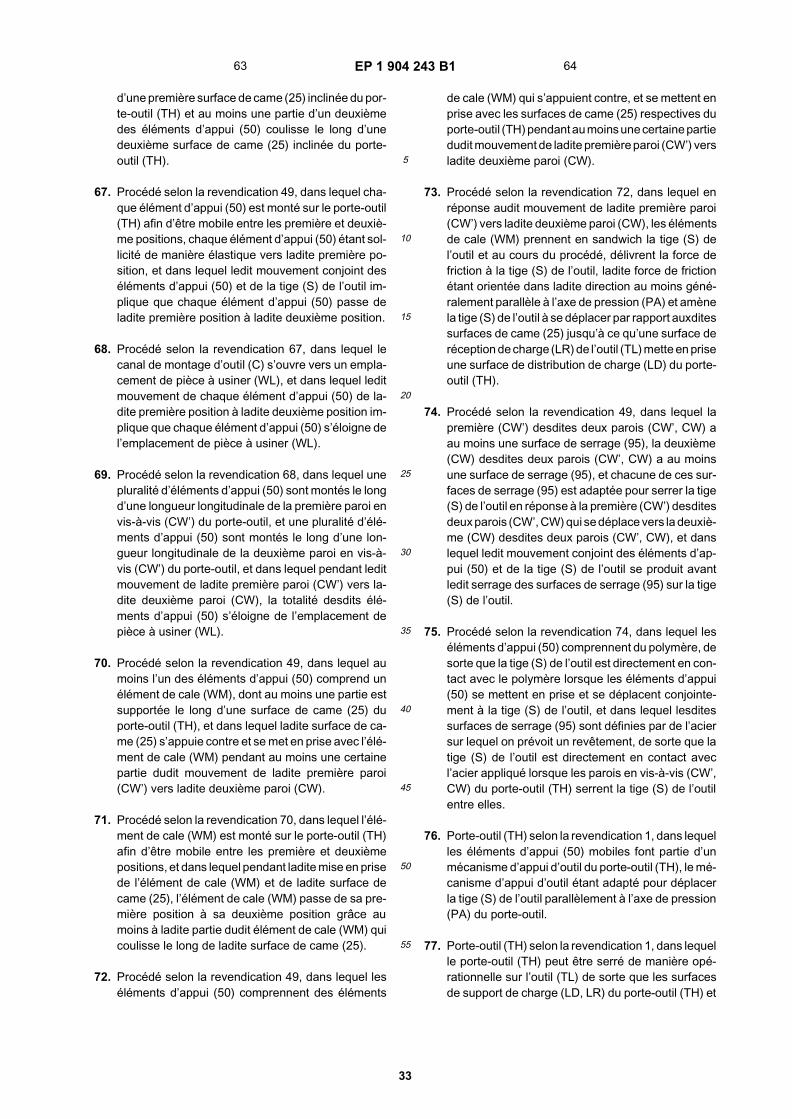
EP 1 904 243 B1
33
5
10
15
20
25
30
35
40
45
50
55
d’une première surface de came (25) inclinée du por-te-outil (TH) et au moins une partie d’un deuxièmedes éléments d’appui (50) coulisse le long d’unedeuxième surface de came (25) inclinée du porte-outil (TH).
67. Procédé selon la revendication 49, dans lequel cha-que élément d’appui (50) est monté sur le porte-outil(TH) afin d’être mobile entre les première et deuxiè-me positions, chaque élément d’appui (50) étant sol-licité de manière élastique vers ladite première po-sition, et dans lequel ledit mouvement conjoint deséléments d’appui (50) et de la tige (S) de l’outil im-plique que chaque élément d’appui (50) passe deladite première position à ladite deuxième position.
68. Procédé selon la revendication 67, dans lequel lecanal de montage d’outil (C) s’ouvre vers un empla-cement de pièce à usiner (WL), et dans lequel leditmouvement de chaque élément d’appui (50) de la-dite première position à ladite deuxième position im-plique que chaque élément d’appui (50) s’éloigne del’emplacement de pièce à usiner (WL).
69. Procédé selon la revendication 68, dans lequel unepluralité d’éléments d’appui (50) sont montés le longd’une longueur longitudinale de la première paroi envis-à-vis (CW’) du porte-outil, et une pluralité d’élé-ments d’appui (50) sont montés le long d’une lon-gueur longitudinale de la deuxième paroi en vis-à-vis (CW’) du porte-outil, et dans lequel pendant leditmouvement de ladite première paroi (CW’) vers la-dite deuxième paroi (CW), la totalité desdits élé-ments d’appui (50) s’éloigne de l’emplacement depièce à usiner (WL).
70. Procédé selon la revendication 49, dans lequel aumoins l’un des éléments d’appui (50) comprend unélément de cale (WM), dont au moins une partie estsupportée le long d’une surface de came (25) duporte-outil (TH), et dans lequel ladite surface de ca-me (25) s’appuie contre et se met en prise avec l’élé-ment de cale (WM) pendant au moins une certainepartie dudit mouvement de ladite première paroi(CW’) vers ladite deuxième paroi (CW).
71. Procédé selon la revendication 70, dans lequel l’élé-ment de cale (WM) est monté sur le porte-outil (TH)afin d’être mobile entre les première et deuxièmepositions, et dans lequel pendant ladite mise en prisede l’élément de cale (WM) et de ladite surface decame (25), l’élément de cale (WM) passe de sa pre-mière position à sa deuxième position grâce aumoins à ladite partie dudit élément de cale (WM) quicoulisse le long de ladite surface de came (25).
72. Procédé selon la revendication 49, dans lequel leséléments d’appui (50) comprennent des éléments
de cale (WM) qui s’appuient contre, et se mettent enprise avec les surfaces de came (25) respectives duporte-outil (TH) pendant au moins une certaine partiedudit mouvement de ladite première paroi (CW’) versladite deuxième paroi (CW).
73. Procédé selon la revendication 72, dans lequel enréponse audit mouvement de ladite première paroi(CW’) vers ladite deuxième paroi (CW), les élémentsde cale (WM) prennent en sandwich la tige (S) del’outil et au cours du procédé, délivrent la force defriction à la tige (S) de l’outil, ladite force de frictionétant orientée dans ladite direction au moins géné-ralement parallèle à l’axe de pression (PA) et amènela tige (S) de l’outil à se déplacer par rapport auxditessurfaces de came (25) jusqu’à ce qu’une surface deréception de charge (LR) de l’outil (TL) mette en priseune surface de distribution de charge (LD) du porte-outil (TH).
74. Procédé selon la revendication 49, dans lequel lapremière (CW’) desdites deux parois (CW’, CW) aau moins une surface de serrage (95), la deuxième(CW) desdites deux parois (CW’, CW) a au moinsune surface de serrage (95), et chacune de ces sur-faces de serrage (95) est adaptée pour serrer la tige(S) de l’outil en réponse à la première (CW’) desditesdeux parois (CW’, CW) qui se déplace vers la deuxiè-me (CW) desdites deux parois (CW’, CW), et danslequel ledit mouvement conjoint des éléments d’ap-pui (50) et de la tige (S) de l’outil se produit avantledit serrage des surfaces de serrage (95) sur la tige(S) de l’outil.
75. Procédé selon la revendication 74, dans lequel leséléments d’appui (50) comprennent du polymère, desorte que la tige (S) de l’outil est directement en con-tact avec le polymère lorsque les éléments d’appui(50) se mettent en prise et se déplacent conjointe-ment à la tige (S) de l’outil, et dans lequel lesditessurfaces de serrage (95) sont définies par de l’aciersur lequel on prévoit un revêtement, de sorte que latige (S) de l’outil est directement en contact avecl’acier appliqué lorsque les parois en vis-à-vis (CW’,CW) du porte-outil (TH) serrent la tige (S) de l’outilentre elles.
76. Porte-outil (TH) selon la revendication 1, dans lequelles éléments d’appui (50) mobiles font partie d’unmécanisme d’appui d’outil du porte-outil (TH), le mé-canisme d’appui d’outil étant adapté pour déplacerla tige (S) de l’outil parallèlement à l’axe de pression(PA) du porte-outil.
77. Porte-outil (TH) selon la revendication 1, dans lequelle porte-outil (TH) peut être serré de manière opé-rationnelle sur l’outil (TL) de sorte que les surfacesde support de charge (LD, LR) du porte-outil (TH) et
63 64

EP 1 904 243 B1
34
5
10
15
20
25
30
35
40
45
50
55
de l’outil (TL) sont mises en prise en tant qu’acces-soire de fermeture du porte-outil (TH) sur l’outil (TL),et sans avoir à comprimer une pointe de l’outil (TL)contre un moule sur une table inférieure de la presse-plieuse.
78. Procédé selon la revendication 49, dans lequel leprocédé implique que le porte-outil (TH) se serre demanière opérationnelle sur l’outil (TL) de sorte queles surfaces de support de charge (LD, LR) du porte-outil (TH) et de l’outil (TL) sont mises en prise commeun accessoire pour fermer le porte-outil (TH) surl’outil (TL) et sans devoir comprimer une pointe del’outil (TL) contre un moule sur une table inférieurede la presse-plieuse.
65 66

EP 1 904 243 B1
35

EP 1 904 243 B1
36
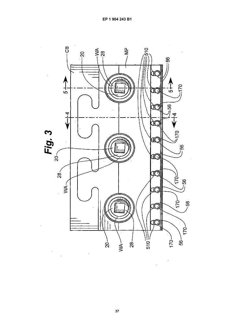
EP 1 904 243 B1
37
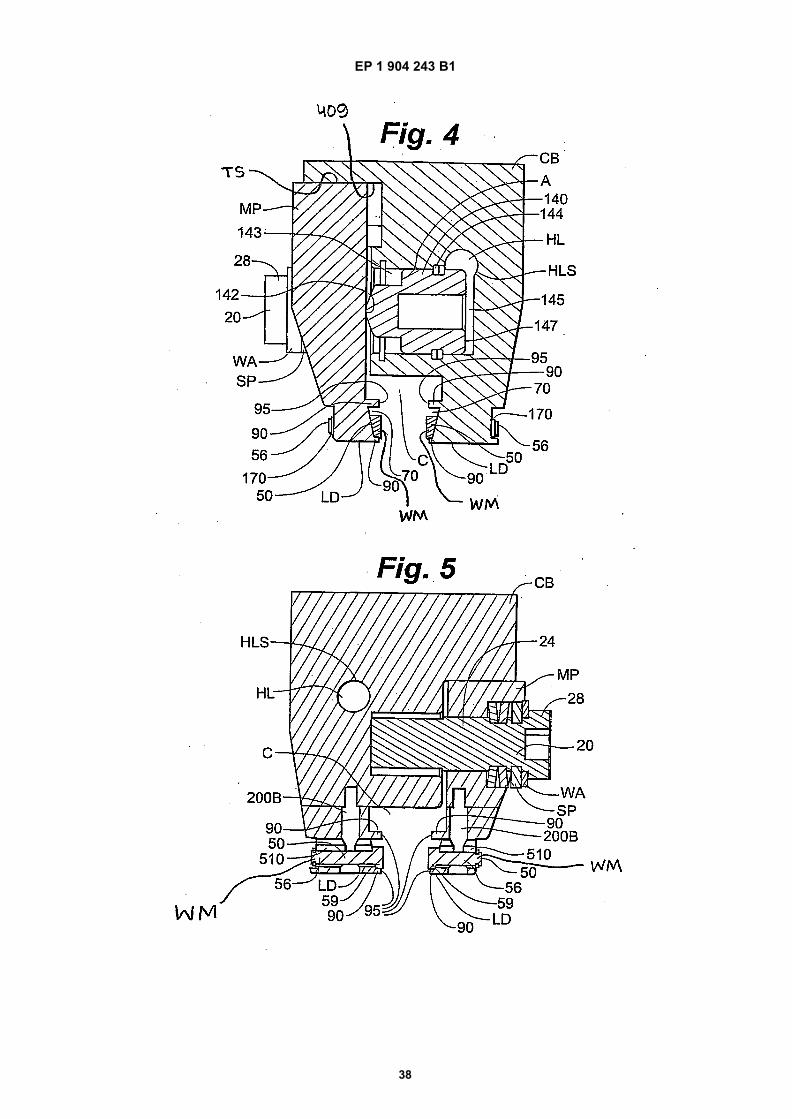
EP 1 904 243 B1
38

EP 1 904 243 B1
39

EP 1 904 243 B1
40

EP 1 904 243 B1
41
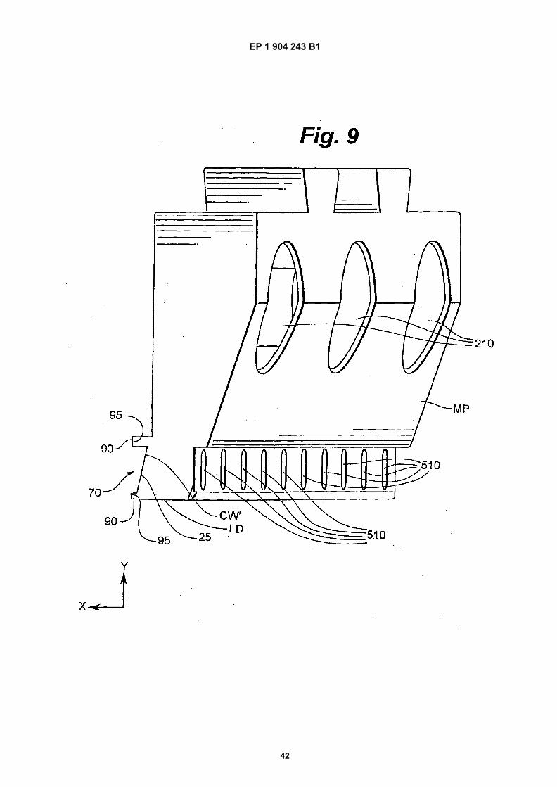
EP 1 904 243 B1
42

EP 1 904 243 B1
43

EP 1 904 243 B1
44

EP 1 904 243 B1
45

EP 1 904 243 B1
46

EP 1 904 243 B1
47
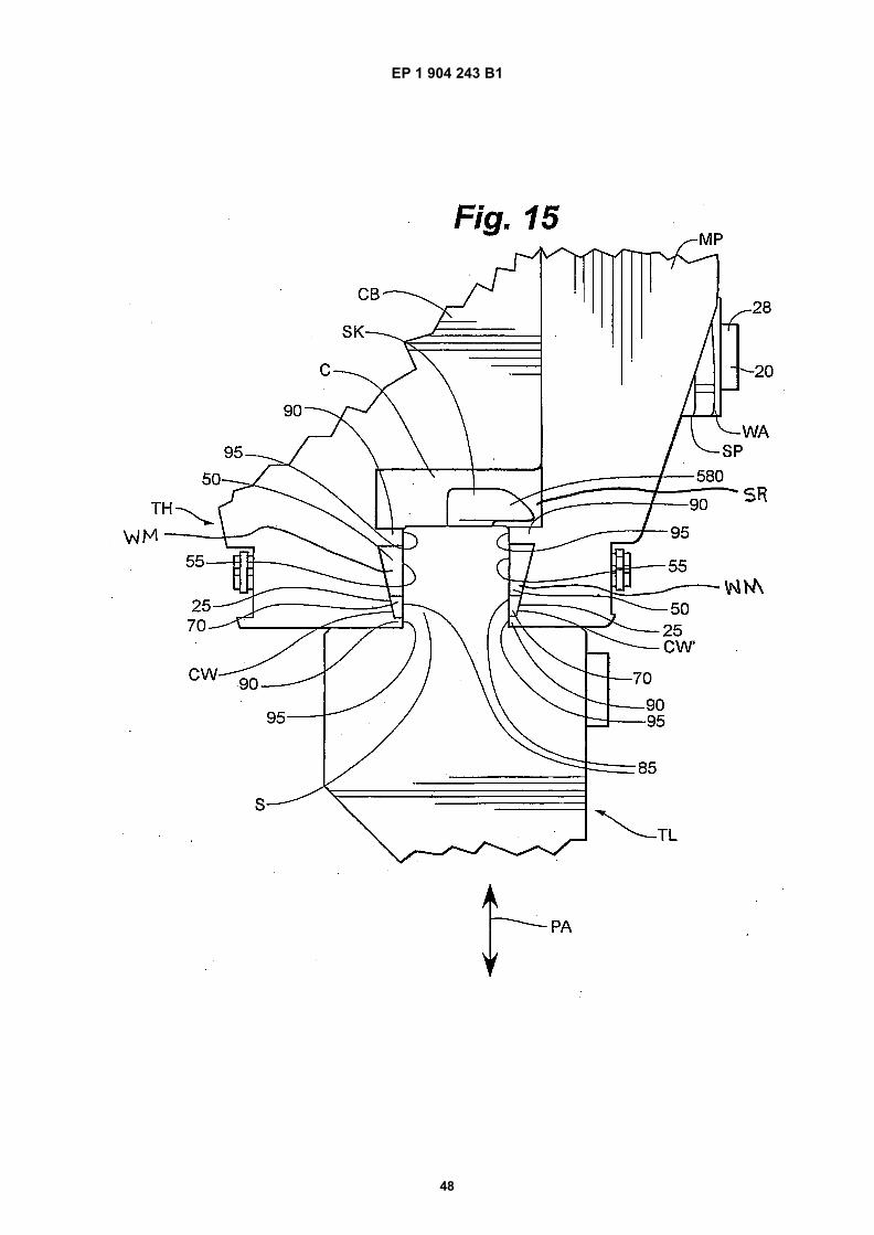
EP 1 904 243 B1
48

EP 1 904 243 B1
49

EP 1 904 243 B1
50

EP 1 904 243 B1
51

EP 1 904 243 B1
52
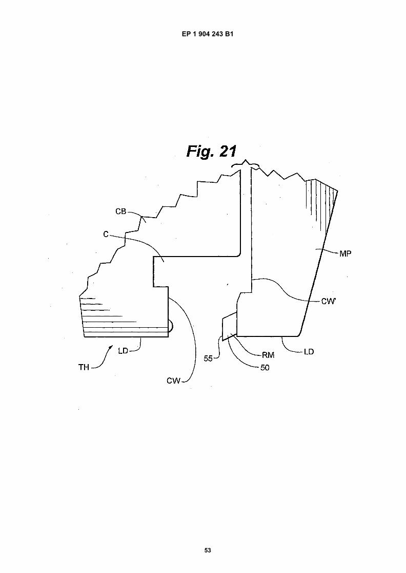
EP 1 904 243 B1
53

EP 1 904 243 B1
54
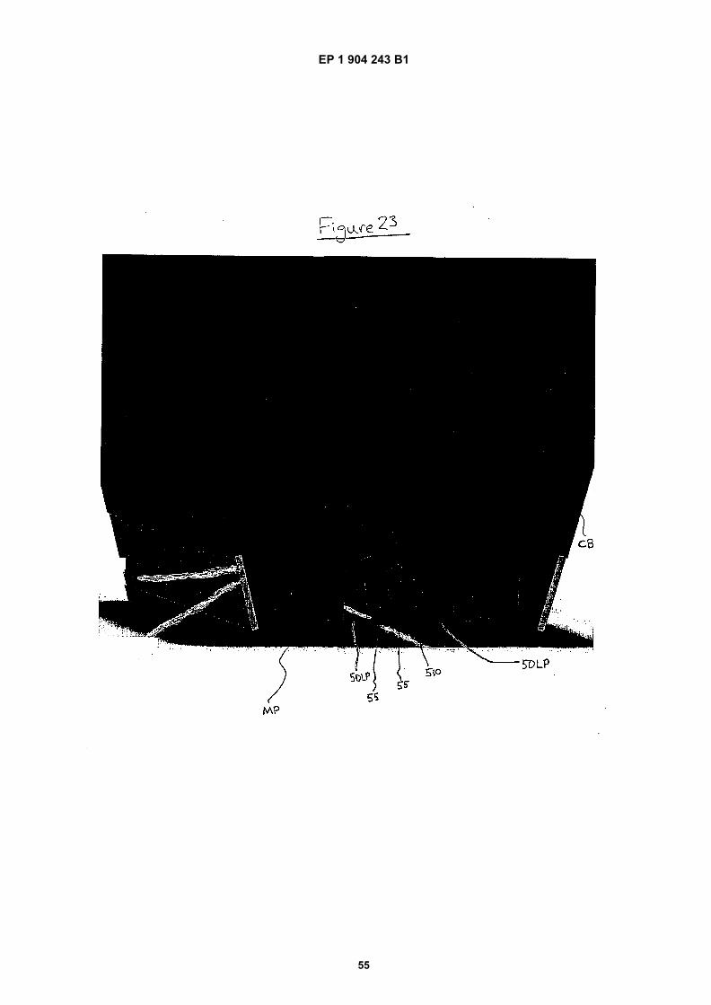
EP 1 904 243 B1
55

EP 1 904 243 B1
56

EP 1 904 243 B1
57

EP 1 904 243 B1
58

EP 1 904 243 B1
59

EP 1 904 243 B1
60
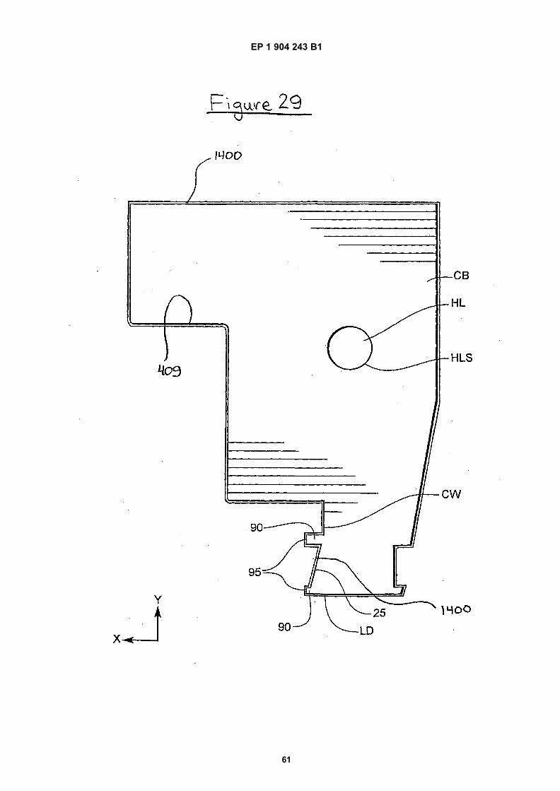
EP 1 904 243 B1
61
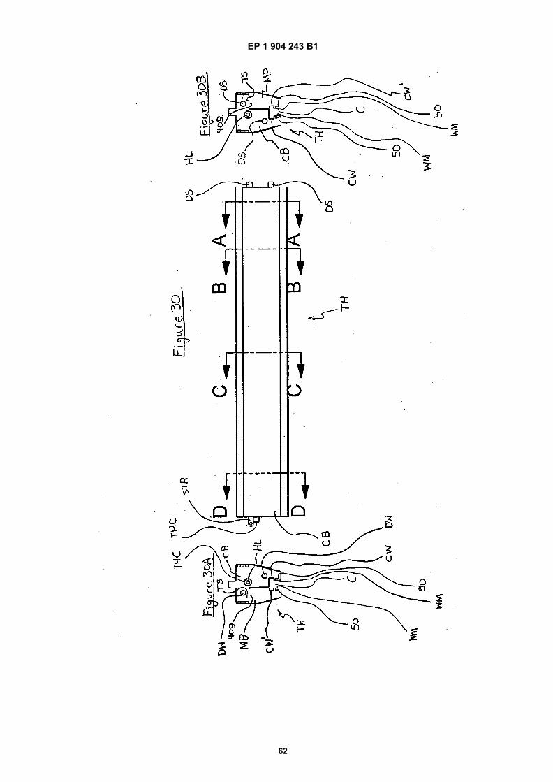
EP 1 904 243 B1
62

EP 1 904 243 B1
63
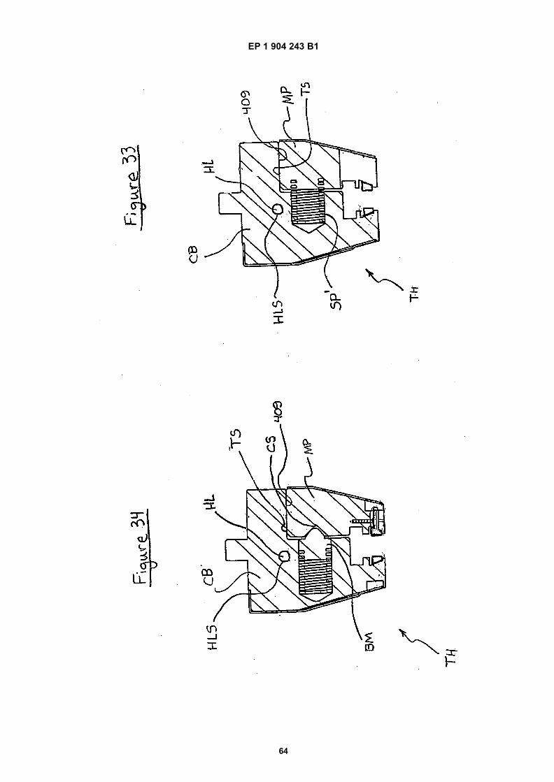
EP 1 904 243 B1
64

EP 1 904 243 B1
65
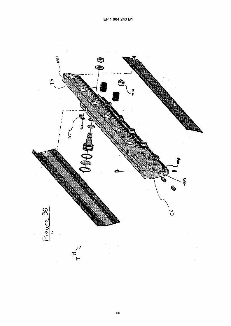
EP 1 904 243 B1
66

EP 1 904 243 B1
67
REFERENCES CITED IN THE DESCRIPTION
This list of references cited by the applicant is for the reader’s convenience only. It does not form part of the Europeanpatent document. Even though great care has been taken in compiling the references, errors or omissions cannot beexcluded and the EPO disclaims all liability in this regard.
Patent documents cited in the description
• WO 02092253 A [0001] [0006]• US 6467327 B, Runk [0022] [0024]• US 742439 A [0022] [0024]• US 6327884 B [0081]
• US 4790888 A [0082]• US 4268323 A [0082]• US 5234721 A [0082]
Non-patent literature cited in the description
• ASM International Handbook Committee. Heat Treat-ing. 1994, vol. 4, 410-424 [0083]