
Properties of tool steel for tool holder application - DiVA-Portal
32
Faculty of Technology and Science Materials Engineering Karlstad University Studies 2008:26 Anna Medvedeva A litterature review Properties of tool steel for tool holder application
-
Upload
khangminh22 -
Category
Documents
-
view
0 -
download
0
Transcript of Properties of tool steel for tool holder application - DiVA-Portal

Faculty of Technology and Science Materials Engineering
Karlstad University Studies2008:26
Anna Medvedeva
A litterature review
Properties of tool steel for tool holder application
Karlstad University Studies
2008:26
Anna Medvedeva
Properties of tool steel for tool holder application
A litterature review

Anna Medvedeva. Properties of tool steel for tool holder application: A litterature review
Research Report
Karlstad University Studies 2008:26ISSN 1403-8099ISBN 978-91-7063-185-6
© The author
Distribution:Karlstad UniversityFaculty of Technology and ScienceMaterials EngineeringSE-651 88 KarlstadSWEDENPhone +46 54 700 10 00
www.kau.se
Printed at: Universitetstryckeriet, Karlstad 2008

Properties of tool steel for tool holder application – A literature review
Anna Medvedeva
Research and Development, Uddeholm Tooling AB, SE-683 85 Hagfors, Sweden Tel.: +46 56317574; fax: +46 56317460 Email address: [email protected] ABSTRACT Large improvements in cutting tool design and technology, including the application of advanced surface engineering treatments on the cemented carbide insert, have been achieved in the last decades. However, the problem of improving the tool body material is not adequately studied. In the present study, the different aspects associated with the steel properties as related to the milling cutter body application are reviewed. The working performance of a tool holder depends in particular on the fatigue strength, high temperature properties and machinability of the steel used. Rotating tools, tool going in and out of cutting engagement, impose dynamic stresses and require adequate fatigue strength off the tool. Different publications, as well as internal investigations at Uddeholm Tooling AB show that the working temperatures of milling cutter bodies in the insert pocket can reach up to 600°C depending on the cutting conditions and material of the workpiece. As a result, a steel for this application needs good hot properties such as high temper resistance, high hot hardness values, etc. Machinability is also essential as machining of the steel represents a large fraction of the production cost of a milling cutter. Its complex shape with flutes and insert pockets as well as small thread holes and small and deep holes for cooling channels require time consuming and advanced machining operations. The essential properties mentioned above were characterized with the emphasis to the steel type, its microstructure and purity, processing and surface treatment and strong interrelations between them. However, the parameters, improving one property, have the opposite effect on another. For example, among the different ways of improving machinability, increasing sulphur content in the steel is by far the most common due to the good deformability of sulphide inclusions under machining. Unfortunately, the deleterious effect of inclusions on fatigue strength is well known. Another example is that it is generally agreed that surface compressive residual stress improves fatigue strength. However, residual stresses tend to relieve at higher temperatures. Secondary hardening steels such as hot work steels are commonly used for tools subjected to thermal exposure to withstand stress relaxation and hardness reduction. However, these steels are generally difficult to machine. The paper is concluded with some general remarks about the current research status of steel properties and problems for further investigations. KEYWORDS: Tool steel, tool holder, fatigue strength, high temperature properties, machinability.
1

CONTENT 1. INTRODUCTION
3
2. PROPERTIES OF TOOL STEEL FOR TOOL HOLDER APPLICATION
4
2.1. Fatigue strength
4
2.1.1. Material strength, hardness and microstructure
6
2.1.2. Residual stress influence
10
2.1.2.1. Machining process
10
2.1.2.2. Surface treatment
11
2.1.3. Inclusion influence
15
2.1.4. Temperature influence
16
2.2. Machinability
18
2.3. High temperature properties – temper resistance and microstructure evolution
21
3. CONCLUSIONS
23
REFERENCES
24
2

1. INTRODUCTION Tool steels have been used for tools, dies, and moulds that shape, form, and cut other materials. Within tool steels, there are various classifications, such as air-hardening tool steels, high-carbon high-chromium tool steels, water-hardening tool steels, oil-hardening tool steels, hot-work tool steels, shock-resisting tool steels, etc. [1]. Appropriate steel selection is essential for the functionality and manufacturability of a tool. There is a growing challenge facing cutting tool manufacturers, tool users and those who provide surface engineering solutions to enhance tool performance. Over the past decades there has been a marked shift in workpiece material utilisation. More easily machinable materials such as cast steel, grey cast iron, tin and copper have been replaced by those with enhanced material properties but which are more difficult to machine, such as tool steel, titanium and nickel based alloys. Components are trending to be machined dry at high speed and leaving very little oversize material. Subsequent the demand on the cutting tools in terms of performance, precision, quality and reliability has been increased. Large improvements in cutting tool design and technology, including the application of advanced surface engineering treatments, have been achieved in the last decades. But the problem of improving the tool body material is not adequately studied. Internal investigation of the milling cutters from different producers at Uddeholm Tooling AB showed that low-alloyed steels are mostly used in milling cutter bodies. Machining in pre-hardened condition is widely used as a production method, some producers use nitriding as a surface treatment of tool bodies. The detailed analysis of the designer’s needs has led us to the conclusion that the following properties of the tool steel are the basic factors influencing the usability of the milling cutter bodies: fatigue strength, machinability and high temperature properties. Fatigue strength is of vital importance in many tool components due to the variable stresses imposed during use. In addition to the necessary fatigue strength, the machinability of the steel is also essential, as machining of steel represents a large fraction of the production cost of a milling cutter because of its complex shape with flutes and insert pockets as well as small thread holes and small and deep holes for cooling channels. Tool steel design problems usually involve conflicting, multiple criteria. Among the different ways of improving machinability, increasing sulphur content in the steel is by far the most common. Unfortunately, the deleterious effect of inclusions on mechanical properties is well known, leading to loss in toughness or fatigue strength. Different publications, as well as internal investigation at Uddeholm Tooling AB show that the working temperatures of milling cutter bodies in the insert pocket can reach up to 600°C depending on the cutting conditions and material of the workpiece. Steel for this application shall have good hot properties such as high temper resistance, high hot hardness values, etc. The following part of this article addresses each of three properties mentioned above considering different aspects involved. Figure 1 shows a survey of aspects associated with the steel properties as related to the milling cutter body application.
3

Figure 1. A survey of aspects reviewed in the paper. Each of the categories contains a number of separate problems, such as properties, microstructure and composition, processing and surface treatment, and the strong interrelationship among them, which are discussed in the paper. The paper is concluded with some general remarks about the present state of the art and problems for further investigations.
2. PROPERTIES OF TOOL STEEL FOR TOOL HOLDER APPLICATION 2.1. Fatigue strength In the middle of the 19th century fatigue was recognised as a fracture phenomenon occurring after a large numbers of load cycles where a single load of the same magnitude would not do any harm. A fundamental step regarding fatigue as a material problem was made in the beginning of the 20th century by Ewing and Humfrey in 1903 [2]. They carried out a microscopic investigation which showed that fatigue crack nuclei start as microcracks in slip bands. In the middle of the 20th century the development of fatigue problems were reviewed in two historical papers by Peterson in 1950 [3] and Timoshenko in 1954 [4]. Peterson refers to the concept of the “endurance limit”, as already defined by Wöhler. Timoshenko in his review discussed the significance of stress distributions and emphasized concentrations around notches and that small radii in the geometry of the part should be avoided. The efforts spent on fatigue investigations in the 20th century are tremendous, as illustrated by numerous publications, e.g. by Mann [5], Schutz [6], Smith [7] and others. Because the fatigue limit is an important material property from an engineering point of view, the experimental technique to determine this property was an important topic in the previous century. Fatigue tests to determine a fatigue limit must be carried on to high numbers of cycles. Such tests are very time consuming and thus expensive, especially if a reasonably large number of tests is carried out in view of information about the statistical variability of the fatigue limit. Statistical procedures for doing so have been standardized, for instance the Staircase method and the Probit method [8]. Fatigue is considered as a phenomenon characterized by microcrack initiation, crack growth as an invisible microcrack and later as a visible macrocrack, which finally leads to complete failure, Figure 2.
4

Figure 2. Different phases of the fatigue life and relevant factors [2]. The crack initiation period may cover a large percentage of the fatigue life under stress amplitudes just above the fatigue limit. But for larger stress amplitudes the crack growth period can be a substantial portion of the fatigue life. The stress intensity factor was introduced by Paris for the correlation between the crack growth rate, da/dN, and the stress intensity factor range, ΔK: da/dN=CΔKm (1) with C and m as experimentally obtained constants. Results of crack growth tests indicated systematic deviations of the Paris equation at relatively high and low ΔK-values. It has led to the definition of three regions in da/dN-ΔK graphs, regions I, II and III respectively, see Figure 3. Fatigue crack growth is no longer possible when Kmax exceeds the fracture toughness (either KC or KIC) and a quasi-static failure occurs. At low K-values the crack driving force is low which affects the crack front microgeometry, the crack front becomes more tortuous, and also the crack closure mechanism is changing [9]. It may then occur that the crack driving force is just no longer capable of producing further crack growth. It should be pointed out that crack initiation and crack growth are both significant for the fatigue life. The crack initiation is easily affected by a number of material surface conditions (surface roughness, surface damage, surface treatments, soft surface layers, surface residual stress). These conditions are important for high-cycle fatigue and the fatigue limit, but they are generally overruled during low-cycle fatigue where plastic deformations at the material surface will occur anyway. Moreover, macro crack growth under low-cycle fatigue is rather limited because small cracks will already induce complete failure at the high stress levels. This implies that low-cycle fatigue is important for special problems where large plastic deformations cannot be avoided. At high plastic strains, material ductility is the prime consideration governing fatigue resistance. Low-cycle fatigue problems are also often associated with high temperature applications.
5
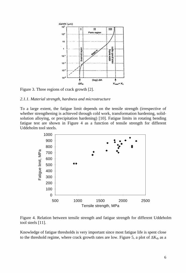
Figure 3. Three regions of crack growth [2]. 2.1.1. Material strength, hardness and microstructure
To a large extent, the fatigue limit depends on the tensile strength (irrespective of whether strengthening is achieved through cold work, transformation hardening, solid-solution alloying, or precipitation hardening) [10]. Fatigue limits in rotating bending fatigue test are shown in Figure 4 as a function of tensile strength for different Uddeholm tool steels.
0100200300400500600700800900
1000
500 1000 1500 2000 2500Tensile strength, MPa
Fatig
ue li
mit,
MP
a
Figure 4. Relation between tensile strength and fatigue strength for different Uddeholm tool steels [11]. Knowledge of fatigue thresholds is very important since most fatigue life is spent close to the threshold regime, where crack growth rates are low. Figure 5, a plot of ΔKth as a
6

function of yield strength for number of steels, shows that ΔKth decreases with increase in yield strength [10].
Figure 5. Threshold as a function of yield strength for various types of steels [10]. Another interesting example, shown in Figure 6, was obtained by Petrak [12] for an alloy steel. The material was heat treated to three different yield stress level, constant ΔK-tests with and without periodic overload cycles were carried out. In tests without peak loads, the crack growth rate was larger if the material was heat treated to higher yield strength. The periodic overload cycles reduced the crack growth rate. The reduction was large for low yield strength steel and much smaller for the high yield strength material. Combined effect of yield stress and grain size on fatigue threshold obtained by Sadananda and Vasudevan, who used the data provided by Tanaka and Soya for different structural steels, is shown in Figure 7 [13]. There is a small decrease of threshold with the product (Yield strength⋅(Grain size)1/2) and also a sharp minimum at some intermediate range of values. Since there is an initial gradual decrease of threshold with increase in the product, the effect of yield strength, which decreases the threshold, appears to have somewhat overriding effect over grain size. Observing the subsequent sharp minimum, one can speculate that there is a critical combination of grain size and yield stress at which there is a drastic reduction in the threshold. There is also possibility that lattice diffusion could become the controlling factor [13]. Additional experimental support is needed to establish the generality of this behaviour. Microstructure may also have relatively little effect on the second region, Figure 3, of crack growth [14], Figure 8. However, it has been found that microstructures may influence region 1 and extend to region 2 [15]. If the heat treatment cycle is varied to make the martensitic phase instead of ferritic, improvements are obtained at low ΔK, Figure 9. Thus, it would appear that substantial improvements in fatigue crack growth resistance near the threshold are possible with microstructural control.
7

Figure 6. Effect of material yield stress on crack growth retardation by overload cycles in 0,34C-7,5Ni-1,1Cr-1,1Mo-4,5Co heat treated to three different stress levels 675, 1235 and 1400 MPa [12].
Figure 7. Combined effect of yield strength and grain size on fatigue threshold [13]. The effect of retained austenite on fatigue properties is reported. There are different results among researches, retained austenite is either useful, harmful or no influence on the fatigue property. The unified opinion has not been obtained yet, however, it seems that there are more reports pointed out a good influence of retained austenite on fatigue [16-18] as follows. The first explanation is that in front of the propagating crack retained austenite transforms to martensite. It results in stress relief at a tip of the fatigue crack by absorption of plastic strain energy. Secondly, the induced transformation results in compressive residual stress and retained austenite which is relatively tough than martensite, plays a role as buffer.
8

Figure 8. Fatigue crack rates for ferritic, martensitic and austenitic microstructures [10].
Figure 9. Rate of crack growth for two microstructures [10].
Another means of microstructural control is the grain size effect on fatigue threshold [19]. Figure 10 shows the beneficial effect of large grain size on thresholds for low strength steels and detrimental effect for high strength steels. The former is considered to be related to a cyclic slip or microstructurally sensitive crack path that is controlled by the grain diameter, whereas for the high strength steel, the effect is considered to be environmentally related [13, 19].
Figure 10. Variation of threshold with grain size for steels [10].
9

Studies on effects of carbides on fatigue behaviour have been limited [16-21]. These reports suggest that fractured carbides can initiate fatigue, acting similarly to cracked inclusions. When stress amplitude is high, a fatigue crack nucleates at a small carbide at the surface or near surface. On the other hand, when stress amplitude is lower, a fatigue crack nucleates at a large carbide particle or carbide clusters in the interior [20]. Large carbides could be fractured easily due to increasing a number of dislocations pile-up at carbides, so carbide cracking is ease to occur when the yield stress is low [16]. It was also reported that crack growth increases with increasing volume fraction of carbides. Due to the brittle nature of carbides crack growth needs less energy compared to alloys where the crack has to grow through a plastically deformable metal phase. To sum up, fatigue improvement originates from the refinement and volume reduction of primary carbides [20]. Hardness of the steel should be also taken into consideration. At low hardness levels fatigue resistance is determined by the matrix behaviour and carbide size and distribution have a minor influence on fatigue [17]. With increased hardness the initiation of microcracks can be shifted towards higher loads. At the other side, the resistance to crack propagation decreases with increased hardness. 2.1.2. Residual stress influence 2.1.2.1. Machining process From the early days of analysing the failures, the detriment of tooling marks has been well recognized. In addition, there is a direct correlation between surface roughness and fatigue. However, typical plots of fatigue strength versus surface roughness in a given material are often produced experimentally by different machining methods, such as turning, milling, grinding, and polishing. It is now realized that variations in residual stress produced in the surface by the machining methods often are the main influence on fatigue life [10, 22-33]. Residual stress pattern induced by machining is critical for component fatigue life, it is generally agreed that surface tensile stress reduces fatigue strength and compressive residual stress improves it. As the cutting operation was not usually employed to finish the parts which a long fatigue life is required, the effect of the cutting process on the fatigue life has not been studied as much as the effect of the grinding process [26]. But the cutting operation as the finishing process has become to play important role in milling cutter production. The insert pocket of the milling cutter where there is a large stress concentrator for fatigue crack initiation is usually milled. It was reported that compressive residual stress and high hardness within the surface layer can be induced by cutting process. This situation can be realized by applying such cutting conditions as a low feed rate, a small corner radius and a chamfered cutting edge tool [28, 32], Figure 11. But hard machining may also produce a phase-transformed layer on the component surface, commonly referred to as white layer [32]. Tool wear is considered to be the dominant factor to induce white layer formation, which is primarily associated with tensile surface residual stress [32], Figure 12.
10

Figure 11. Effect of feed on residual stress profile [32].
Figure 12. Effect of tool wear/white layer on residual stress profile [32].
2.1.2.2. Surface treatment Carburising Improvements in bending fatigue strength can be produced by carburising, which results in compressive residual stresses being generated close to the carburised surface. The residual stress profile below the surface arises from a sequence of phase transformations that occurs during quenching after carburising [33-39]. Differences in carbon content between the core and the carburised case are primarily responsible for this sequence changing the transformation behaviour during quenching. Another factor contributing to these stresses is the normal volume change that occurs upon quenching of austenite. Stress profiles depend on the case depth and the base carbon content, the highest compressive stress occurs at the shortest case depth and lowest carbon content in the core. The influence of core hardenability on the residual stresses may be explained in terms of the change in the Ms temperature. An increase in the hardenability, and hence shorten the time between the transformation in the core and in the higher carbon case. As a result the residual stresses will be less compressive and the fatigue limit will be decreased, Figures 13 a and b. An internally oxidised layer is a common feature of components which have been gas carburized. Normally the atmosphere is controlled such that it is reducing to iron. However, for certain elements in solid solution, which have a greater affinity for oxygen, for example Mn, Cr, Si, this atmosphere is potentially oxidising. The oxygen diffuses along grain boundaries and the oxidised grain boundaries may act as an initiation site for a fatigue crack. Since the oxidised layer influences the fatigue strength, the elimination of this layer by controlling the addition of elements in the base composition susceptible to internal oxidation [40] should lead to a higher fatigue strength because crack initiation will become more difficult.
11

a
b
Figure 13. a – Residual stress profiles for steels with high and low core hardenability, b – Relationship between fatigue limit and core hardenability [34]. Nitriding Plasma nitriding has been widely used in industrial production as a common surface modification treatment in which nitrogen is introduced into steel or other iron based alloys at elevated temperatures (between 400 °C and 520 °C) [41]. The influence of plasma nitriding on fatigue behaviour of various steels has been studied by several researchers. Fatigue life of nitrided specimens is reported to be longer than non-nitrided specimens. It was considered that crack initiation sites for nitrided specimens were shifted to interior of specimens because of generation of hardened layer and compressive stress near specimen surface by nitriding, while fatigued cracks generated at or near surface for non-nitrided specimens, Figure 14 [42, 43].
Figure 14. Appearance of fracture surface in crack initiation region of plasma nitrided samples [47].
Figure 15. Relationship between fatigue strength and stress concentration factor for nitrided and non-nitrided samples [43].
12

The nitriding treatment improves fatigue strength of the notched specimens more than the smooth ones [43, 48], Figure 15. It can be also seen that the nitriding treatment reduced the fatigue notch factor by about 0.5. It has been reported that fatigue limit increases with increasing depth and surface hardness of nitrided layer, but the thickness of the compound layer does not affect the fatigue limit [44-46]. However, due to the formation of a heterogeneous microstructure in the outer layers of nitrided components, fatigue life may be reduced. This phenomenon has been reported for stainless steels [47, 48] and high strength alloys [49]. Consequently, the effect of compressive residual stress and heterogeneous microstructure must be considered simultaneously, in studying the fatigue behaviour of nitriding process. Shot peening Shot peening has proved to be powerful instruments in enhancing the fatigue resistance of steel components by producing the compressive work hardened layer on the surface of the component. [48, 50-53]. Compressive residual stress is the result of a difference of plastic deformation between surface and interior. Every shot strike creates a dimple. The surface and a small volume under the dimple are stretched. The rest of the part tries to restore this area to his original shape, stressing this area in compression. Overlapping dimples develop an uniform layer of compressive residual stress. The three characteristics points of a compressive residual stress profile are [50]: - maximum compressive residual stress, normally just below the surface. If shot
peening is processed in good conditions it reaches 70% of material yield strength after cold working.
- surface stress, usually less than maximum, - depth of compressive layer. Shot peening is a cyclic cold working process which can modify material mechanical characteristics. As a consequence residual stress profile will be influenced by cold working and coverage rate because magnitude of compressive residual stress is directly linked to mechanical characteristics of the material. When material hardness increases, magnitude of compressive stress will increase, and as soon as when material hardness decreases magnitude of compressive stress will decrease and depth of compressive stress will increase. The stability of residual stresses induced by shot peening at different loadings was studied by V. Schulze [51]. At thermal loading creep processes which are due to dislocation climbing lead to residual stress relaxing with increasing time and temperature [51], Figure 16. Figure 17 shows the longitudinal residual stresses at quasi-static tensile and compressive loading. With increasing material hardness the residual stresses as well as the loading stresses necessary to initiate residual stress relaxation increase. While at the normalized state and the state quenched and tempered at 650°C the residual stresses change their sign twice during tensile and once at compressive loading, they remain in the compressive region at tensile loading of the state quenched and tempered at 450°C. The residual stress relaxation rate generally is smaller at compressive than at
13
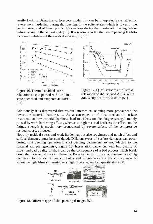
tensile loading. Using the surface-core model this can be interpreted as an effect of severe work hardening during shot peening in the softer states, which is lower in the hardest state, and of lower plastic deformations during the quasi-static loading before failure occurs in the hardest state [51]. It was also reported that warm peening leads to increased stabilities of the residual stresses [51, 53].
Figure 17. Quasi-static residual stress relaxation of shot peened AISI4140 in differently heat treated states [51].
Figure 16. Thermal residual stress relaxation at shot peened AISI4140 in a state quenched and tempered at 450°C [51]. Additionally it is discovered that residual stresses are relaxing more pronounced the lower the material hardness is. As a consequence of this, mechanical surface treatments at low material hardness lead to effects on the fatigue strength mainly caused by work hardening effects, whereas at high material hardness the effects on the fatigue strength is much more pronounced by severe effects of the compressive residual stresses induced. Not only residual stress and work hardening, but also roughness and notch effect and surface damages must be considered. Different types of surface damages can occur during shot peening operation if shot peening parameters are not adapted to the material and part geometry, Figure 18. Incrustation can occur with bad quality of shots, and bad quality of shots can be the consequence of a bad process which break down the shots and do not eliminate its. Burrs can occur if the shot diameter is too big compared to the radius peened. Folds and microcracks are the consequence of excessive high Almen intensity, very high coverage, and bad quality shots [50].
Figure 18. Different type of shot peening damages [50].
14

This non exhaustive list of shot peening effects emphasize that optimization of shot peening parameters is a complex process. To a great extent this optimization is empirical because shot peening effects are difficult to measure and it is not possible to replace expensive and long fatigue tests by computer modelling which are still at the early development stages. Laser shock processing Laser shock processing (LSP) consists of irradiating a metallic target with a short (about 20 ns) and intense (>1013 Wm-2) laser light in order to generate, through a high pressure surface plasma (> 1 GPa), a plastic deformation and a surface strengthening within materials. Recent reported studies on steels and aluminium alloys displayed appreciable improvements in fatigue limits of laser shock processed samples compared with base and shot peened materials. In spite of higher compressive stresses introduced by shot peening, the difference between shot peening and LSP improvements (11-20 versus 22-35%) was associated with greater delay of the crack initiation in the case of LSP because of the larger depths (between 1 and 2 mm) affected by compressive stresses after LSP [54]. Coatings The beneficial effect of thin coatings deposited is well known in terms of improvement in strength and wear resistance. On the other hand any coating may drastically reduce the fatigue life of a component due to cracks starting in the coating and propagating into the substrate material. Considering, for instance, chrome-plate and nickel-plate parts, they show improved wear behaviour, but also a shorter fatigue life with respect to those of uncoated part [55]. Recently some studies were addresses to the investigation of the effect of different PVD coatings on the fatigue behaviour and pointed out an improvement in fatigue resistance by the high level of compressive residual stress affecting the coating [56-58]. 2.1.3. Inclusion influence Inclusions have a superimposing effect on the fatigue strength of components as they are stress concentrations for fatigue crack initiation [59-62]. The stress state around an inclusion highly influence crack initiation and determined by particle size and shape, residual stresses and inclusion orientation. Among a number of factors affecting the harmfulness of different inclusion types, inclusion size transverse to loading direction is probably the most important parameter [61]. The composition of the inclusion is also of significance, globular calcium aluminates appear to be more detrimental than elongated manganese sulphides [59]. Inclusion shape is also of importance since it influences the stress field inside and around the inclusion. Smooth inclusions cause less stress concentration in the surrounding matrix than sharp edged inclusions. Stresses generated by inclusions within the surrounding matrix material arise after material working or heat treatments. For heat treatments, the thermal expansion coefficient is crucial. Inclusions with lower coefficients than the iron matrix are most damaging because they introduce residual tensile stresses within the steel matrix
15

around the inclusion. MnS are often harmless, because they introduce, as a result of their larger expansion coefficient, compressive stresses. The effect of inclusions on fatigue crack growth is less pronounced than on fatigue crack initiation. For example, sulphide inclusions do not significantly affect the fatigue crack growth rate, however, the sulphide inclusions affect the residual fatigue life in terms of tolerable crack length [60], Figure 19.
a b Figure 19. a – Fatigue crack growth rate curve, b – relationship between crack length and number of cycles to failure for 12wt% Cr steels with different sulphur content [60]. At higher volume fractions of inclusions, however, it is likely that another inclusion is present within the plastic zone surrounding a crack tip. If this inclusion is bonded weakly to the matrix, it will generate a strain field and thus contribute to crack propagation. This behaviour with secondary cracking enhances with increasing inclusion aspect ratio a/b (where a is the axis perpendicular to and b is the axis parallel to the loading direction). The large difference in stress concentration between longitudinally and short transversally oriented inclusions is a main cause for the substantial amount of fatigue growth anisotropy in forged inclusion reach steel [61]. 2.1.4. Temperature influence The effect of residual surface stress on fatigue tends to diminish as temperatures are increased. The free energy of a material is raised during deformation by generation of dislocations and interfaces, and a material containing these defects is thermodynamically unstable [63]. That is why at higher working temperatures, e.g. from 300 to 600°C for some tool components, the influence and behaviour of the compressive residual stresses are more uncertain and they tend to relieve. Not only the
16

residual stresses but also the material substructure and its dislocation characteristics are of importance. Earlier investigations have shown that stress relaxation and dislocation recovery is not a single microstructural process but a series of micromechanisms depending on a number of parameters. These include the material type, its microstructure and purity as well as the strain level and working temperature [63]. It has also been demonstrated that residual stress relief increases with increasing time and temperature [51]. There are two primary processes, annihilation and rearrangement of dislocations into lower energy configurations, which explain the stress relaxation due to the thermal exposure [63]. Precipitation of secondary particles, carbides, for example, may affect the dislocation reconfiguration (dislocations themselves promote the heterogeneous nucleation of precipitates), increasing stress relaxation resistance in secondary hardening steels. During the annihilation and rearrangement of dislocations, the particles may pin dislocations and thus inhibit their movement. Smaller, finely coherent particles are more preferable for stronger pinning. Combining thermal effects and mechanical loading in isothermal fatigue lead also to microstructural changes causing cyclic hardening and/or softening of the steel. Earlier investigations have shown that the fatigue life is strongly connected to the softening [64]. It was also found that the softening consists of three stages: a rapid initial stress amplitude softening, a stable second stage that occupies the main part of the life and a final fracture softening. The first stage, occupying only a few cycles of the specimen life (less than 3%), depends on the total strain range. Indeed, the higher the strain amplitude, the higher the stress values and the shorter the stage duration. The second stage of the curve is almost independent of the total strain at each test temperature. This stage follows an analytical expression of the type: σ=A⋅N-S, (2) where σ is the peak tensile stress of the hysteresis loop, N the number of cycles, S the cyclic softening coefficient and A is a constant that depends on temperature. S, equal to the slope of the linear stage in the log-log diagram, represents the cyclic softening [65]. Researchers have proposed various mechanisms and their combinations explain the softening behaviour of steels: resolution of precipitates in the matrix after being cut by dislocations to a size smaller than the critical size for particle nucleation [66]; over-aging of precipitates which leads to the growing of precipitates into coarsely distributed stable ones [65]; and rearrangement of dislocation substructure into a dislocation subgrain structure of lower internal stress [65-68]. It is also believed that lower carbon steels with a higher martensitic start temperature, Ms, have a higher dislocation density than higher carbon steels [69]. Consequently, a structure with higher dislocation density that softens with dislocation rearrangement mechanism will show a higher cyclic softening coefficient [65]. Isothermal fatigue lives are in general plotted as a function of stress and strain range. Life is defined corresponding to an arbitrary crack depth, ranging from 0.1 to 1.5 mm. Therefore, a unique criterion for fatigue life prediction does not exist. In general the
17

fatigue life curves are temperature dependent, but based on the plastic strain range. For a particular steel grade a master isothermal Manson-Coffin curve can rationalize isothermal fatigue life from room to high temperatures, Figure 20. Taking into account the scattering in data, this curve can predict the fatigue life with reasonable accuracy. A more resistant steel, longer life, would have a lower inelastic strain per cycle for a prescribed total strain. Therefore, retarding the thermally or plastically induced softening would result in a better fatigue life [70].
Figure 20. Plastic strain and fatigue life in isothermal fatigue for different hot work tool steels and test conditions [70]. 2.2. Machinability Machining of steel represents a large fraction of the production cost of a milling cutter because of its complex shape with flutes and insert pockets as well as small thread holes and small and deep holes for cooling channels. Problems arise because there are so many practitioners. Each one of them carries out a wide variety of operations, each with different criteria of machinability. A material may have good machinability by one criterion, but poor machinability by another. Also, machinability may change when a different type of operation is being carried out, for example, turning versus milling, or when the tool material is changed. Despite the lack of a universal metric, machinability may be assessed by one or more of the following criteria: - Tool life. The amount of material removed by a tool under particular cutting
conditions before the tool performance becomes unacceptable or the tool is worn by a standard amount.
- Limiting rate of metal removal. The maximum rate at which the material can be machined for a standard tool life.
- Cutting forces. The forces acting on the tool or the power consumption under particular cutting condition.
- Surface finish. The surface finish achieved under specified cutting conditions. - Chip shape. It influences the clearance of the chips from around the tool under
specified cutting conditions [71].
18

When cutting the tool steels, temperature generated in tools has a major influence on the rate of tool wear and on the limit of the rate of metal removal. There are some explanations of steel behaviour in terms of their composition, structure, heat treatment and properties. Alloying elements in steels (carbon, manganese, chromium, etc.) which increase its strength raise the stresses acting on the tool and the temperature generated and, in this way, reduce maximum rate of metal removal when cutting. However, mechanisms of alloying element influence on the interface temperature are not fully understood. Flow-zone is the most difficult region to study because of the small size and inaccessibility of the critical volume of metal. It was found out that two steels with differences in carbon contents (0,04% versus 0,4%) show the same temperature gradient and the same tool wear pattern, but at a much lower speed. In general, carbide rich steels are difficult to machine because they promote a high wear rate of the cutting tool. On the other hand, the tough material can form a built-up edge which cause chipping of the cutting tool and alter its geometry. Fragments of the built-up edge which break away on the newly formed work surface leave it very rough. Moreover, the chip breakage and its transport are also impaired cutting the tough steel [71]. Cemented carbides tools with chip breakers are proposed to be useful in this case but speed, feed and depth of cut are to be adjusted. Manganese sulphides in steels are appreciated as constituents for their beneficial role during machining. They in the component material help to save machining costs by chip embrittlement, tool protection and flow zone improvements [72]. For machining purposes, MnS that act as stress raisers in the shear plane at the tip of the tool are to be favoured. They result in thinner chips and lower tool forces and lower power consumption. When using carbide tools, sulphides are found covering the contact area on the tool rake face. This may prevent the formation of a built-up edge at lower cutting speed. At medium cutting speeds, MnS seems to act as a lubricating layer interposed between tool and work material on the rake face. Figure 21a shows a photomicrograph of the contact area on the rake surface of carbide tool after cutting steel with MnS. Figure 21 b is the sulphur EDX mapping of this region, which shows a high concentration of sulphide over the whole contact area. The mechanisms by which the MnS particles are deposited on the tool surface is not certain. It has been suggested that they are extruded onto the tool surface from their “sockets” in the steel, like toothpaste from a tube, and retain there by bonds formed between the MnS and the carbides of the tool material [71]. To sum up, manganese sulphides improve machinability best for low to medium cutting speeds. To be effective, however, enough sulphur must be present in the work material. High sulphur content in steel promotes the machinability, but very low sulphur content makes machining more difficult. Figure 22 shows the rates of flank wear increase with decreasing sulphur content.
19

Figure 21. a – Sulphides on the rake face of carbide tool after cutting steel with MnS at medium cutting speed, b – sulphur EDX mapping of the same tool [71].
Figure 22. Influence of sulphur in steels on the rate of flank wear [71]. Steels, de-oxidized with aluminium alone, content the hard and rigid non-metallic inclusions, such as Al2O3 accelerate the abrasive tool wear. However, Ca-treated steels show the improvements in machinability. By deoxidizing steel with Ca, Ca-rich oxides form that improves machinability, especially, at high cutting speeds, specially when using cemented carbide tools. Furthermore, Ca additions lead to more rounded MnS inclusions, which promote isotropic mechanical behaviour [72]. Yield strength of steels is influenced by both composition and heat treatment. When steels are heat treated to high strength and hardness, the stress which they impose on tools during cutting may become high enough to deform the cutting edge. Cemented carbides can be used to cut steels with higher hardness. Even here, tool life becomes very short or cutting speeds become very low when the hardness exceeds 500 HV. Higher rate of metal removal and longer tool life can be achieved with ceramic tools and cubic boron nitride tools. However, as they are less tough than cemented carbides, the range of operations on which they can be used is restricted. Additionally, tool costs are very high.
20

2.3. High temperature properties – temper resistance and microstructure evolution
Elevated temperature hardness and temper resistance are important steel properties for milling cutter applications as they are subjected to high temperatures during use (from 300 to 600°C depending on cutting condition, machined material and the dimension of a milling cutter). Secondary hardening steels such as hot work steels can be applicable in this case. In particular, the hardness-temperature characteristics above the secondary hardening peak temperature are of special interest (temper resistance). Microstructurally, the temper resistance of a steel is determined by the changes in character of alloy-element carbides at elevated temperature. Above the temperature corresponding to maximum hardness, the fine carbides will coarsen progressively and the dislocation-rich martensite structure becomes more and more recovered. Thus, an improved temper resistance is to be expected if the coarsening of fine carbides can be postponed, this will be also have the effect of delaying recovery, thereby making a further contribution to an effective counteraction of high temperature softening (fine particles inhibit the dislocation movements giving delayed recovery) [73]. The most convenient method for increased temper resistance is to use a secondary hardening reaction involving the precipitation of alloy carbides. Molybdenum, chrome and vanadium are important alloying elements in this context which form MC, M2C, M23C6 carbides during tempering [74]. However, the secondary hardening response is rather weak if only vanadium is present. From other work, Mo-addition to at least 1% is necessary in order to get an acceptable degree of secondary hardening combined with satisfactory temper resistance [75]. It is found that the carbon content to obtain the required secondary hardening response is 0,3-0,4% [74]. A considerable amount of early work was carried out on changes in microstructure during tempering of AISI H13 hot work tool steels with additions of 5% Cr, up to 1,5% Mo and 1% V. The most stable carbide in this type of steel is VC that precipitates during tempering of about 500-550°C in which some molybdenum is dissolved. During overaging at high tempering temperatures the VC coarsens slowly and M23C6 is precipitated, possibly at the expense of some dissolution of VC [73-74, 76-78]. Increasing the austenitising temperature by taking more VC into solution increases the intensity of secondary hardening and, thereby, also the overaged hardness at any given tempering temperature. But other effects also control the intensity of secondary hardening, such as increasing the misfit between the lattices of the VC and the matrix ferrite and, especially, the composition of the steel in terms of the V:C ratio. It is well known that maximum intensity of secondary hardening occurs at a V:C ratio equal to that the stoichiometry of VC itself, because at that V:C ratio the temperature dependence of the solubility of VC is a maximum. Hence more VC is available for precipitation [74]. An increase in the intensity of secondary hardening by increasing the mismatch between the VC and ferrite matrix can be done by decreasing the lattice parameter of the matrix or by increasing the lattice parameter of the VC. The former can be achieved by an increased silicon content and the latter by an increased molybdenum content. In addition, chromium dissolved in VC decreases the lattice parameter of VC and causes more rapid overaging. The amount of M23C6 formed during overaging and the rate of replacement of VC by M23C6 can be decreased by a lower chromium
21

content [73]. Figure 23 summarizes the temperature ranges over which various carbides are stable during secondary hardening and subsequent softening of AISI H13 hot work tool steel and QRO 80 (0,4C – 2,5Cr – 2Mo – 1,2V). Secondary MC precipitates grow faster in H13 as compared with QRO80. Furthermore, a transition from MC to M23C6 proceeds in H13 during tempering at temperatures higher than 550°C while M23C6 is not formed before 690°C in QRO80. Finally, recent works have indicated that fine stable carbides retard the recovery and recrystallization of the tempered martensite matrix during overaging.
Figure 23. Temperature ranges over which various carbides are stable during secondary hardening and subsequent softening of AISI H13 and QRO 80 tool steels [73]. It was mentioned that the increased intensity of secondary hardening can be achieved by increasing the silicon content. As silicon inhibits the coarsening of cementite and promotes its dissolution, carbon is available to form alloy carbides increasing the amount carbides and, consequently, the hardness of the steel tempered at the secondary hardening peak temperature. However, this happens at lower tempering temperatures, while the secondary hardening peak of low silicon grade is shifted towards higher temperatures, Figure 24. Thus, reducing the silicon content in steels tempered above the secondary hardening peak results in a possible use of the tool in higher in-service temperatures [76].
Figure 24. Qualitative influence of silicon content on the secondary hardening peak [76].
22

Ni was reported to have no effect on the chemical composition of secondary carbides. However, a shift of the precipitation towards the population of larger carbides was observed [77]. Nickel addition in AISI H11 significantly decreased the volume fraction of the population of small carbides 1,5 nm. One proposed explanation is that nickel decreases the solubility of carbon in the martensitic matrix leading to a greater supersaturation effect. The higher carbon supersaturation promotes the formation of alloyed carbides and then accelerates the secondary hardening process [77]. 3. CONCLUSIONS The review presents the current research status of steels properties that are important for milling cutter body applications: fatigue strength, machinability and hot properties. Previous investigations provide the information about the factors influencing each of the steel property and some methods of their improving. However, the parameters, improving one property, have the opposite effect on another. For example, among the different ways of improving machinability, increasing sulphur content in the steel is by far the most common due to the good deformability of sulphide inclusions under machining. Unfortunately, the deleterious effect of inclusions on mechanical properties is well known, leading to loss in fatigue strength. Adding to this, there is the effect of the machining in itself, as of surface roughness and surface residual stress. Finally, there is the machined geometry, often complicated and with small radii, creating large stress concentrations. However, as the effect of inclusion content on fatigue strength is usually evaluated on smooth polished specimens, the combined effect of inclusions, surface condition and geometrical stress concentrator is not adequately studied. Another example is that it is generally agreed that surface compressive residual stress improves fatigue strength, and many tool producers try to introduce them in the crack initiation site by machining the tool in hardened conditions or by means of different surface treatments. However, residual stresses tend to relieve at higher temperatures. The studies show that there is relatively few literature available concerning the mechanisms of stress relaxation and method of its improving. Furthermore, as the hot properties are of vital importance in milling cutter applications, the tool steel with pronounced temper resistance and microstructure stability is needed. Secondary hardening steels such as hot work steels are commonly used for tools subjected to thermal exposure. However, these steels are generally difficult to machine and machining of such steels represents a large fraction of the production cost of the tool. The presented review show that there is a high demand of investigations of the influence of various alloying elements and material microstructure on the steel machinability and, specially, different ways to improve it. Therefore, it is of great benefit to develop a steel grade for improved tool holder performance combining all the demanding properties and optimizing them by better understanding the effecting parameters and mechanisms involved.
23

REFERENCES [1] G. Roberts, G. Krauss, R. Kennedy, Tool steels, ASM International, 5th edition, 1998. [2] J. Schijve, Fatigue of structures and materials in the 20th century and the state of the art, International Journal of Fatigue 25, 2003, 679-702. [3] R. E. Peterson, Discussion of a century ago concerning the nature of fatigue, and review of some of the subsequent researches concerning the mechanism of fatigue, ASTM Bulletin, 164, American Society for Testing and Materials, 1950, 50-56. [4] S. Timoshenko, Stress concentration in the history of strength of materials, The William M.Murray Lecture, SESA, 1954, 12:1-12. [5] J. Y. Mann, Aircraft fatigue – with particular emphasis on Australian operations and research, Symp of ICAF, Centre d’Essais Aeronautique de Toulouse, 1983. [6] W. Schutz, A history of fatigue, Engng Fract Mech, 1996, 263-300. [7] R.A. Smith, Fatigue crack growth, 30 years of progress, Pergamon, 1986. [8] A guide for fatigue testing and the statistical analysis of fatigue data, ASTM STP No.91-A. Philadelphia, PA: American Society for Testing and Materials, 1963. [9] J. Schijve, Fatigue crack closure observations and technical significance. Mechanics of fatigue crack closure, American Society for Testing and Materials, Philadelphia ,1988, 5–34. [10] ASM Handbook: Fatigue and Fracture, Vol. 19, ASM International, Materials Park, Ohio, 1996. [11] S. Johansson, The fatigue properties of tool steels, Swedish Symposium on High Performance Steel: for Engineering Applications, Uddeholm, 1989. [12] G.S. Petrak, Strength level effects on fatigue growth and retardation, Eng. Fract. Mech., Vol 6, 1974, 725-733. [13] K. Sadananda, A.K. Vasudevan, Fatigue crack growth mechanisms in steels, International Journal of Fatigue, 25 , 2003, 899-914. [14] S.T. Rolfe, J. M. Barsom, Fracture and fatigue control in structures – application of fracture mechanics, Prentice-Hall, 1977. [15] H. Suzuki, A. J. McEvily, Microstructural effects on fatigue crack growth in a low carbon steel, Met. Trans. A, Vol 10, 1979, 475-481. [16] Daien Yokoi, Nobuhiro Tsujii, Kenzo Fukaura, Effects of tempering temperature and stress amplitude on low-cycle fatigue behaviour of a cold-work tool steel, Materials Science Research International, Vol. 9, No. 3, 2003, 216-222. [17] C. Broeckmann, A. Packeisen, W. Theisen, Fatigue of carbide rich materials, Proceedings of the 6th International Tooling Conference, Italy, 2006. [18] C. Broeckmann, Microstructure and mechanical properties of tool steels, Proceedings of the 5th International Tooling Conference, Austria, 1999, 45-58. [19] R. O. Ritchie, Near-threshold fatigue crack propagation in steels, International Metals Reviews, Vol 24, No 5-6, 1979, 205-230. [20] Kenzo Fukaura, Yoshihiko Yokoyama, Daien Yokoi, Nobuhiro Tsujii, Kanji Ono, Fatigue of cold-work tool steels: effect of heat treatment and carbide morphology on fatigue crack formation, life, and fracture surface observations, Metallurgical and Materials Transactions, Vol. 35A, 2004, 1289-1300.
24

[21] C. Broeckmann. Mechanische Eigenschaften, Berns,H. Hartlegierungen und Hartverbundwerkstoffe, Springer Verlag, Berlin, New York, 1998, 125-154. [22] W. Koster, Effects of residual stress on fatigue of structural alloys, Practical application of residual stress technology, ASM International, 1991, 1-10. [23] X. Yang, C. Richard Liu, A methodology for predicting the variance of fatigue life incorporating the effects of manufacturing process, Journal of Manufacturing Science and Engineering, August 2002, Vol. 124, ASME, 745-753. [24] T. Segawa, H. Sasahara, M. Tsutsumi, Development of a new tool to generate compressive residual stress within a machined surface, International Journal of Machine Tools and Manufacture 44, 2004, 1215-1221. [25] J. Y. Zhang, S. Y. Liang, G. Zhang, D. Yen, Modeling of residual stress profile in finish hard turning, Materials and Machining Processes, 21, 2006, 39-45. [26] L. P. Taraov, Effects of grinding direction and of abrasive tumbling on the fatigue limit of hardened steel, Am.Soc.Test.Mater., 58, 1958, 528-539. [27] F. Ghanem, C. Braham, M.E. Fitzpatrick, H. Sidhom, Effect of near-surface residual stress and microstructure modification from machining on the fatigue endurance of a tool steel, Journal of Materials Engineering and Performance, Vol. 11(6) December 2002, 631-639. [28] H. Sasahara, The effect on fatigue life of residual stress and surface hardness resulting from different cutting conditions of 0.45%C steel, International Journal of Machine Tools and Manufacture 45 (2005) 131-136. [29] H. Sasahara, T. Obikawa, T. Shirakashi, Prediction model of surface residual stress within the machined surface by combining two orthogonal plane models, Int. J. Mach. Tools Manuf., 44, 7-8, 2004, 815-822. [30] Y. Matsumoto, D. Magda, D. W. Hoeppner, T. Y. Kim, Effect of maching processes on the fatigue strength of hardened AISI 4340 steel, Trans. ASME J.ENG. IND. 113, 1991, 154-159. [31] J. Rech, A. Moisan, Surface integrity in finish hard turning of case hardened steel, Int. J. Mach. Tools Manuf. 43, 5, 2003, 543-550. [32] Dale W. Schwach, Y.B. Guo, Feasibility of producing optimal surface integrity by process design in hard turning, Materials Science and Engineering A 395, 2005, 116-123. [33] R. J. Bucci, Effect of residual stress on fatigue crack growth rate measurements, STP 743, ASTM, 1981, 28-47. [34] S. Preston, Bending fatigue strength of carburising steel SS 2506, Material Science and Technology, Vol. 7, February, 1991, 105-110. [35] C. Kim, D. E. Diesburg, Fracture of case-hardened steel in bending, Engineering Fracture Mechanics, Vol 18, 1, 1983, 69-82. [36] O. Sandberg, Influence of Ca treatment on fatigue properties of case hardening steel SS 2506, Report IM-2114, Swedish Institute for Metals Research, 1986. [37] T. Hillskog, O. Sandberg, Relation between alloying content and mechanical properties of three low alloyed case hardening steels, Report IM-2162, Swedish Institute for Metals Research, 1987. [38] S. Preston, Evaluation of vanadium as a microalloying addition in a carburising steel, Report IM-2395, Swedish Institute for Metals Research, 1988.
25

[39] S. Preston, Literature survey on optimising the metallurgical and mechanical properties of case carburised components, Report IM-2239, Swedish Institute for Metals Research, 1987. [40] S. Preston, A. Melander, Influence of silicon on the fatigue and fracture properties of carburised steels, Report IM-2500, Swedish Institute for Metals Research, 1989. [41] ASM Metals Handbook, vol. 4, Heat Treating, ninth ed., American Society for Metals, Metals Park, OH, 1991. [42] A. Alsaran, I. Kaymaz, A. Celik, F. Yetim, M. Karakan, A repair process for fatigue damage using plasma nitriding, Surface & Coatings Technology 186, 2004, 333-338. [43] C. M. Suh, J. K. Hwang, K. S. Son, H. K. Jang, Fatigue characteristics of nitrided SACM 645 according to the nitriding condition and notch, Materials Science and Engineering A 392, 2005, 31-37. [44] A. Celik, S. Karadeniz, Improvement of fatigue strength of AISI 4140 steel by an ion nitriding process, Surface and Coatings Technology 72, 1995, 169-173. [45] K. Genel, M. Dominkol, M. Capa, Effect of ion nitriding on fatigue behaviour of AISI 4140 steel, Materials Science and Engineering A 279, 2000, 207-216. [46] Y. Sun, T. Bell, Plasma surface engineering of low alloy steel, Materials Science and Engineering A 140, 1991, 419-434. [47] S. Ganesh Sundara Raman, M. Jayaprakash, Influence of plasma nitriding on plain fatigue and fretting fatigue behaviour of AISI 304 austenitic stainless steel, Surface and Coatings Technology 201, 2007, 5906-5911. [48] G. H. Farrahi, H. Ghadbeigi, An investigation into the effect of various surface treatments on fatigue life of a tool steel, Journal of Materials Processing Technology 174, 2006, 318-324. [49] M. Guagliano, L. Vergani, Effect of nitriding on low-cycle fatigue properties, International Journal of Fatigue 19, 1997, 67–73. [50] O. Higounenc, Correlation of shot peening parameters to surface characteristic, Proceedings of the 9th International Conference on Shot Peening, Paris, 2005, 28-35. [51] V. Schulze, Stability of surface changes induced by mechanical surface treatments, Proceedings of the 9th International Conference on Shot Peening, Paris, 2005, 420-428. [52] N. Iwata, Y. Tomota, K. Katahira, H. Suzuki, Effect of shot peening on fatigue fracture for an as quenched martensitic steel, Materials Science and Technology 18, 2002, 629-632. [53] A. Tange, K. Ano, Improvement of spring fatigue strength by new warm stress shot peening process, Materials Science and Technology 18, 2002, 642-648. [54] P. Peyre, R. Fabbro, L. Berthe, C. Dubouchet, Laser shock processing of materials, physical processes involved and examples of applications, Journal of laser applications 8, 1996, 135-141. [55] M. P. Nascimento, R. C. Souza, W. L. Pifatin, HJ. C. Voorwald, Effects of surface treatments on the fatigue strength of AISI 4340 aeronautical steel, International Journal of Fatigue, 23, 2001, 607-625. [56] M. Gelfi, G.M.La Vecchia, N. Lecis, S. Troglio, Relationship between through-thickness residual stress of CrN-PVD coatings and fatigue nucleation sites, Surface and Coatings Technology 192, 2005, 263-268.
26

[57] S. Baragetti, G.M. La Vecchia, A. Terranova, Fatigue behavior and FEM modeling of thin-coated components, International Journal of Fatigue 25, 2003, 1229-1238. [58] S. Baragetti, G.M. La Vecchia, A. Terranova, Variables affecting the fatigue resistance of PVD-coate components, International Journal of Fatigue 27, 2003, 1541-1550. [59] A. Melander, M. Rolfsson, A. Nordgren, B. Jansson, H. Hedberg, T. Lund, Influence of inclusion contents on fatigue properties of SAE 52100 bearing steels, Scandinavian Journal of Metallurgy 20, 1991, 229-244. [60] V.P. Raghupathy, V. Srivivasan, H. Krishman, M.N. Chandrasekharaiah, The effect of sulphide inclusions on fracture toughness and fatigue crack growth in 12% Cr steels, Journal of Material Science 17, 1982, 2112-2126. [61] C.Temmel, B. Karlsson, N.G. Ingesten, Fatigue anisotropy in cross-rolled, hardened medium carbon steel resulting from MnS inclusions, Metallurgical and Materials Transactions A 37A, 2006, 2995-3007. [62] Y. Bergengren, M. Larsson, A. Melander, Influence of machining defects and inclusions on the fatigue properties of a hardened spring steel, Swedish Institute for Metals Research, Stockholm, 1993. [63] F.J. Humphreys, M. Hatherly, Recrystallization and related annealing phenomena: Pergamon, UK, 2002. [64] J. Sjöström, J. Bergström, Proceedings of the 6th International Conference on Tooling, Karlstad, 2002, p.603. [65] A.F. Armas, C. Petersen, R. Smitt, et al., Mechanical and microstructural behaviour of isothermally and thermally fatigued ferritic/martensitic steels: Journal of nuclear materials 307-311, 2002, p.509. [66] S.Suresh, Fatigue of materials, Cambridge, England, 1998. [67] J. Sjöström, Doctoral thesis, Chromium martensitic hot work tool steels – damage, performance and microstructure, Karlstad, 2004. [68] N. Mebarki, P. Lamelse, D. Delagnesand, et al., Proceedings of the 6th International Conference on Tooling, Karlstad, 2002, p. 617. [69] R. Redd-Hill, R. Abbaschian, Physical Metallurgy Principles, PWS Publishing Company, Boston, 1994. [70] J. Bergström, F. Rezai-Aria, High temperature fatigue of tool steels, Proceedings of the 6th International Tooling Conference, May 2006, Torino. [71] E.M. Trent, P.K. Wright, Metal cutting. 4th ed., Butterworth-Heinemann, USA, 2000. [72] R. Kiessling, Nonmetallic inclusions and their effects on the properties of ferrous alloys, in Encyclopedia of Materials: science and Technology, Bernhard Ilschner, ed., Elsevier Science Ltd., Oxford, UK, 2001, 6278-83. [73] B. Lehtinen, W. Roberts, Microstructural changes during tempering of hot work tool steels – a comparison of AISI H13 and UHB QRO 80, Swedish Institute for Metals Research, Sweden. [74] F.B. Pickering, The properties of tool steels for mould ad die applications, Sheffield City Polytechnic, England. [75] P. Westerhult, W. Roberts, Properties of AISI H13 type hot work tool steels with varying Mo:V ratios. Swedish Institute for Metals Research report No. 1689, 1982.
27

28
[76] D. Delagnes, P. Lamelse, M.H. Mathon, N. Mebarki, C. Levaillant, Influence of silicon content on the presentation of secondary carbides and fatigue properties of a 5% Cr tempered martensitic steel, Materials Science and Engineering A 394, 2005, 435-444. [77] P. Michaud, D. Delagnes, P. Lamesle, M.H. Mathon, C. Levaillant, Influence of chemical composition on the precipitation of secondary carbides in modified AISI H11 hot work tool steels, Proceedings of the 6th International Tooling Conference, May 2006, Torino. [78] A. Grellier, M. Siaut, A new hot work tool steel for high temperature and high stress service conditions, Proceedings of the 6th International Tooling Conference, May 2006, Torino.

Properties of tool steel for tool holder application
Large improvements in cutting tool design and technology have been achieved in the last decades. In the present study, the different aspects associated with the steel properties as related to the milling cutter body application are reviewed. The working performance of a tool holder depends in particular on the fatigue strength, high tem-perature properties and machinability of the tool steel used.
Rotating tools, tool going in and out of cutting engagement, impose dynamic stresses and require adequate fatigue strength off the tool. Different publications, as well as internal investigations at Uddeholm Tooling AB show that the working temperatures of milling cutter bodies in the insert pocket can reach up to 600°C depending on the cutting conditions and material of the workpiece. As a result, steel for this application needs good hot properties such as high temper resistance and high hot hardness values. Machinability is also essential as machining of the steel represents a large fraction of the production cost of a milling cutter. Its complex shape with flutes and insert pockets as well as small thread holes and small deep holes for cooling channels require time consuming and advanced machining operations.
The essential properties mentioned above were characterized with the emphasis to the steel type, its microstructure and purity, processing and surface treatment and strong interrelations between them.
Karlstad University StudiesISSN 1403-8099
ISBN 978-91-7063-185-6