
Hemming of Aluminum Alloy Sheets Using Electromagnetic Forming
9
-
Upload
independent -
Category
Documents
-
view
4 -
download
0
Transcript of Hemming of Aluminum Alloy Sheets Using Electromagnetic Forming

Hemming of Aluminum Alloy Sheets UsingElectromagnetic Forming
Jianhui Shang, Larry Wilkerson, and Steve Hatkevich
(Submitted October 30, 2010; in revised form April 25, 2011)
Hemming is usually the last stage of production for automotive closures, and therefore has a critical effecton the quality of the final assemblies. The insufficient formability of aluminum alloys creates a considerableproblem in the hemming process. To address this issue, electromagnetic forming was utilized to hemaluminum alloy sheets. Electromagnetic forming is a high strain rate forming process that is currently beinginvestigated by both academia and industry. Past studies have shown that the formability of metals can besignificantly improved during electromagnetic forming, which benefits the hemming of aluminum alloys.This article presents the experimental results of hemming Al 6061-T6 sheets using electromagnetic forming.The effects of the parameters of electromagnetic hemming on the hem quality are discussed. In addition, thenumerical simulation results of electromagnetic hemming are presented to enhance the understanding ofthe process and to determine the efficacy on an industrial scale.
Keywords aluminum alloys, electromagnetic forming, hemming
1. Introduction
Hemming is a process that bends the edge of a metal sheet to180� or more. It serves several functions: to increase the partstiffness, to eliminate the acute edge, to improve the appearanceof highly visible panel edges, and to join the inner and outerparts. Hemming is usually applied as the final stage ofproduction for automotive closures. Therefore, hemming iscritical to the actual part function, as well as the assemblyquality.
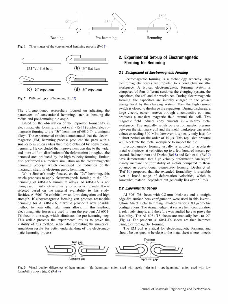
Conventional hemming is a three-step process: bending, pre-hemming, and final hemming (Fig. 1). The first step (bending)is to bend the edge of a metal sheet to 90�. The second step(pre-hemming) is to bend the part 45� more, and the final step(hemming) is to fold the edge to 180� and create the hem union.
Hemming can be broadly categorized as two types: ‘‘2t’’ and‘‘3t’’ (Fig. 2). A ‘‘2t’’ hem involves only a single sheet, and a‘‘3t’’ hem involves two sheets (outer and inner). A fully flathem requires materials with good formability, such as steel,because of the sharp hem radius that is required. For thematerials with low formability, rope hems with larger hem radiiare used to avoid strain localization and cracking produced byexceeding the forming limits.
Current initiatives in automotive industry are driving a needfor stronger and lighter automotive panels. Light metals, suchas aluminum alloys and magnesium, are being developed toreduce overall body weight and improve fuel economy.However, their lower formability tends to create considerable
problems. Aluminum alloys are difficult to hem because of theirsusceptibility to strain localization, which produces cracking onthe flat hem edges (Ref 3). Thus, a rope hem instead of a flathem is usually used for aluminum alloys.
A flat hem is more desirable than a rope hem because it hasa better visual quality (Fig. 3). Carsley (Ref 4) identified the‘‘apparent gap’’ as the distance between the tangent break linesof adjacent hemmed parts. The ‘‘apparent gap’’ is smallerbetween two flat hemming unions than it is between two ropehemming unions, which creates a better perception of overallquality (Ref 4).
There are several parameters to evaluate the hem quality ofparts. One is the hem union radius, which is the distancebetween the edge of the hem union and the tangent break point(Fig. 3). The hem union radius is an important qualityparameter for the ‘‘apparent gap.’’ Another important hemquality parameter is ‘‘roll-in/roll-out’’, which refers to theposition change of the bent edge after hemming (Ref 2). Largeroll-in/roll-out could cause problems in the assembly stage.Therefore, these two parameters will serve as the basis toevaluate the hem quality in this study.
Several studies have been performed to improve the hemquality of aluminum alloys. Lin et al. (Ref 5) performed acomputational design-of-experiment study for aluminum alloy6111-T4 flat surface-straight edge ‘‘3t’’ hemming. They foundthat the pre-hemming die angle and the bending die radiussignificantly affect the roll-in/roll-out, and the pre-strain and thebending die radius greatly impact the maximum surface strain.Golovashchenko (Ref 6) presented a new method for the ‘‘3t’’hemming of aluminum alloy 6111-T4. He applied a largerbending radius to redistribute the plastic strain. This newmethod allowed an additional 10% of pre-strain through theentire forming and assembly operations, and made it possiblefor the ‘‘3t’’ flat hemming of 6111-T4. Muderrisoglu et al.(Ref 7) carried out an experimental study on the ‘‘2t’’ hemmingof aluminum alloy 1050. The results showed that crackswere observed on the outer surface over the bending area.
Jianhui Shang, Larry Wilkerson, and Steve Hatkevich, AmericanTrim LLC, Lima, OH 45801. Contact e-mail: [email protected].
JMEPEG �ASM InternationalDOI: 10.1007/s11665-011-9988-y 1059-9495/$19.00
Journal of Materials Engineering and Performance
The aforementioned researchers focused on adjusting theparameters of conventional hemming, such as bending dieradius and pre-hemming die angle.
Based on the observation of the improved formability inelectromagnetic forming, Jimbert et al. (Ref 1) applied electro-magnetic forming to the ‘‘3t’’ hemming of 6016-T4 aluminumalloys. The experimental results demonstrated that the electro-magnetic (EM) hemming process produced the parts with asmaller hem union radius than those obtained by conventionalhemming. He concluded the improvement was due to the widerand more uniform distribution of the deformation throughout thehemmed area produced by the high velocity forming. Jimbertalso performed a numerical simulation on the electromagnetichemming process, which confirmed the reduction of themaximum strain in electromagnetic hemming.
While Jimbert�s study focused on the ‘‘3t’’ hemming, thisarticle proposes to apply electromagnetic forming to the ‘‘2t’’hemming of 6061-T6 aluminum alloys. Al 6061-T6 is notbeing used in automotive industry for outer skin panels. It wasselected based on the material availability to this study.Besides, Al 6061-T6 exhibits low uniform elongation and highstrength. If electromagnetic forming can produce reasonablehemming for Al 6061-T6, it would provide a new possiblemethod to hem other aluminum alloys. In this method,electromagnetic forces are used to hem the pre-bent Al 6061-T6 sheet in one step, which eliminates the pre-hemming step.This article presents the experimental results to prove theviability of this method, while also presenting the numericalsimulation results for better understanding of the electromag-netic hemming process.
2. Experimental Set-up of ElectromagneticForming for Hemming
2.1 Background of Electromagnetic Forming
Electromagnetic forming is a technology whereby largeelectromagnetic forces are imparted to a conductive metallicworkpiece. A typical electromagnetic forming system iscomposed of four different sections: the charging system, thecapacitors, the coil and the workpiece. During electromagneticforming, the capacitors are initially charged to the pre-setenergy level by the charging system. Then the high currentswitch is closed to discharge the capacitors. During discharge, alarge electric current moves through a conductive coil andproduces a transient magnetic field around the coil. Thismagnetic field induces eddy currents in a nearby metalworkpiece. The mutually repulsive electromagnetic pressurebetween the stationary coil and the metal workpiece can reachvalues exceeding 300 MPa; however, it typically only lasts fora short period on the order of 10 ls. This repulsive pressurewill accelerate the metal workpiece to impact the die.
Electromagnetic forming usually is applied to acceleratemetal workpieces at velocities up to a few hundred meters persecond. Balanethiram and Daehn (Ref 8) and Seth et al. (Ref 9)have demonstrated that high velocity deformation can signif-icantly increase the formability of metals compared to thoseobtained in conventional quasi-static forming. Daehn et al.(Ref 10) proposed that the extended formability is availableover a broad range of deformation velocities, which issomewhat material dependent but generally lies over 50 m/s.
2.2 Experimental Set-up
Al 6061-T6 sheets with 0.8 mm thickness and a straightedge-flat surface hem configuration were used in this investi-gation. Sheet metal hemming involves various 3D geometricconfigurations. The straight edge-flat surface hem configurationis relatively simple, and therefore was studied here to prove thefeasibility. The Al 6061-T6 sheets are manually bent to 90�(Fig. 4). The pre-bent Al 6061-T6 sheets are then hemmedusing electromagnetic forming.
The EM coil is critical for electromagnetic forming, andshould be designed to be close to the metal sheet where it needs
Fig. 3 Visual quality differences of hem unions—‘‘flat-hemming’’ union used with steels (left) and ‘‘rope-hemming’’ union used with lowformability alloys (right) (Ref 4)
90° 45°
180°
Bending Pre-hemming Hemming
Fig. 1 Three stages of the conventional hemming process (Ref 1)
(b) “3t” flat hem(a) “2t” flat hem
(d) “3t” rope hem (c) “2t” rope hem
Fig. 2 Different types of hemming (Ref 2)
Journal of Materials Engineering and Performance
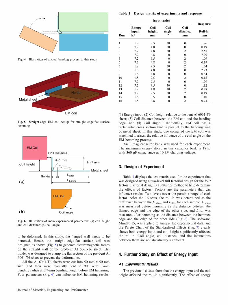
to be deformed. In this study, the flanged wall needs to behemmed. Hence, the straight edge-flat surface coil wasdesigned as shown (Fig. 5) to generate electromagnetic forceson the straight wall of the pre-bent Al 6061-T6 sheet. Theholder was designed to clamp the flat section of the pre-bent Al6061-T6 sheet to prevent the deformation.
All the Al 6061-T6 sheets were cut into 50 mm x 50 mmsize, and then were manually bent to 90� with 1-mmbending radius and 7-mm bending height before EM hemming.Four parameters (Fig. 6) can influence EM hemming results:
(1) Energy input; (2) Coil height relative to the bent Al 6061-T6sheet; (3) Coil distance between the EM coil and the bendingedge; and (4) Coil angle. Traditionally, EM coil has arectangular cross section that is parallel to the bending wallof metal sheet. In this study, one corner of the EM coil wasmachined to assess the relative influence of the coil angle on theEM hemming process.
An Elmag capacitor bank was used for each experiment.The maximum energy stored in this capacitor bank is 18 kJwith 360 lF capacitance at 10 kV charging voltage.
3. Design of Experiment
Table 1 displays the test matrix used for the experiment thatwas designed using a two-level full factorial design for the fourfactors. Factorial design is a statistics method to help determinethe effects of factors. Factors are the parameters that caninfluence results. Two levels cover the possible range of eachfactor. After the 16 tests, the roll-in was determined as thedifference between the Lbefore and Lafter for each sample. Lbeforewas measured before hemming as the distance between theflanged edge and the edge of the other side, and Lafter wasmeasured after hemming as the distance between the hemmededge and the edge of the other side (Fig. 6). The software,Minitab 15, was applied to analyze the experimental data, andthe Pareto Chart of the Standardized Effects (Fig. 7) clearlyshows both energy input and coil height significantly affectedthe roll-in. Coil angle, coil distance, and the interactionsbetween them are not statistically significant.
4. Further Study on Effect of Energy Input
4.1 Experimental Results
The previous 16 tests show that the energy input and the coilheight affected the roll-in significantly. The effect of energy
Fig. 4 Illustration of manual bending process in this study
EM coil
Holder
Metal sheet
Fig. 5 Straight-edge EM coil set-up for straight edge-flat surfacehemming
Coil angle
EM Coil
(b)
EM Coil
Coil height
Coil Distance
R=1 mmH=7 mm
(a)
Metal sheetLafter
Lbefore
Roll-in
Fig. 6 Illustration of main experimental parameters: (a) coil heightand coil distance; (b) coil angle
Table 1 Design matrix of experiments and response
Run
Input variesResponse
Energyinput,kJ
Coilheight,mm
Coilangle,
�
Coildistance,
mmRoll-in,mm
1 1.8 9.5 30 0 1.962 7.2 4.8 30 0 0.193 7.2 4.8 30 2 2.554 7.2 4.8 0 0 7.295 7.2 9.5 0 2 1.096 7.2 4.8 0 2 0.197 1.8 9.5 30 2 1.748 1.8 4.8 30 0 2.239 1.8 4.8 0 0 0.6410 1.8 9.5 0 2 0.1511 7.2 9.5 0 0 1.2912 7.2 9.5 30 0 1.1213 1.8 4.8 30 2 0.2814 7.2 9.5 30 2 0.1915 1.8 9.5 0 0 1.1016 1.8 4.8 0 2 0.73
Journal of Materials Engineering and Performance

input will be studied in this section. Table 1 indicates that thecoil height of 9.5 mm tended to produce smaller roll-in than thecoil height of 4.8 mm. Therefore, the experimental conditionsof 9.5-mm coil height, 0-mm coil distance, and 0� coil anglewere chosen for the study of energy input. The four levels ofenergy input were applied to hem the Al 6061-T6 sheets thatwere pre-bent to 90�. Each sample was cut down the middle,polished, and then photographed in a cross-sectional view. Asshown in Fig. 8, the tangent break point was determined as thetangent point of the straight bottom surface line of the flatsection to the hem union curve. Then the distance between thetangent break point and the hem union edge was measured fromthe photo as the hem union radius. The roll-in was measured asthe edge position change relative to the other side edge beforeand after hemming (Fig. 6). Following are the cross-sectionalviews of the samples for EM hemming with different energyinputs (Fig. 8-11).
Subsequently, the summary of the effects of energy input onthe roll-in and the hem union radius is shown (Fig. 12). It showsthat the roll-in decreased with the increase of energy input.However, excessive energy input (7.20 kJ) resulted in anincreased roll-in. The hem union radius decreased with theincrease of energy input from 2.70 kJ to 3.24 kJ. But at an energyinput of 3.60 kJ, the hem union was bent upwards significantlyand had a larger hem union radius (6.5 mm). When the energyinput was increased to 7.2 kJ, the hem union radius decreased to2.9 mm. It should be noted that at an energy input of 7.20 kJ, thebending edge impacted onto the flat section and the flat sectionwas no longer flat. This is an unacceptable hem condition.
Based on the results of this analysis, an energy input of3.24 kJ produced a smaller hem union radius with a smallerroll-in, and thereby produced the best hem quality among thefour test conditions.
4.2 Comparison Between EM and Conventional Hemming
An Al 6061-T6 sheet was hemmed via conventionalhemming to compare to EM hemming. As in the case of theEM tests, the part was manually bent to 90� (Fig. 4), then
Fig. 7 Pareto chart of the standardized effects
Fig. 8 Cross-sectional view after EM hemming with 2.70 kJenergy input (roll-in: 0.84 mm; hem union radius: 4.3 mm)
Fig. 9 Cross-sectional view after EM hemming with 3.24 kJenergy input (roll-in: 0.61 mm; hem union radius: 3.8 mm)
Fig. 10 Cross-sectional view after EM hemming with 3.60 kJenergy input (roll-in: 0.40 mm; hem union radius: 6.5 mm)
Fig. 11 Cross-sectional view after EM hemming with 7.20 kJenergy input (roll-in: 0.73 mm; hem union radius: 2.9 mm)
0
0.1
0.2
0.3
0.4
0.5
0.6
0.7
0.8
0.9
2 3 4 5 6 7 8
Energy input (kJ)
Rol
l-in
(mm
)
2
2.5
3
3.5
4
4.5
5
5.5
6
6.5
7
Hem
uni
on r
adiu
s (m
m)
Roll-in Hem union radius
Fig. 12 Effects of energy input on roll-in and hem union radius(coil height: 9.5 mm)
Journal of Materials Engineering and Performance
pre-hemmed to 135�, and then hemmed to 180�. The resultingpart was cut down the middle, polished, and photographed in across-sectional view (Fig. 13). The roll-in and the hem unionradius were determined with the same methods used for the EMhemming.
Comparing Fig. 13 to Fig. 9, the EM hemmed part at3.24 kJ had a smaller roll-in than the part produced withconventional hemming, which indicates that the EM hemmedpart had a better dimensional accuracy. Moreover, the EMhemmed part had a smaller hem union radius than the partproduced with conventional hemming. The smaller ‘‘apparentgap’’ produced by the EM hemming process suggests that EMhemmed parts may have a better overall perceived quality thana conventionally hemmed part.
It should be noted that the conventional hemming part inFig. 13 was manually bent and hemmed, and does not representthe current state-of-the-art for aluminum alloy hems. However,the results of this study do demonstrate that the EM hemmingprocess produces a competitive hem quality for representativealuminum alloy hems. They also indicate that this process maybe feasible on an industrial scale. Clearly, optimization isnecessary to refine the EM hemming technique and to improvethe overall hem quality.
5. Numerical Simulation
5.1 Simulation Model Development
Electromagnetic forming is a complex forming process,involving mechanical, thermal and electromagnetic phenom-ena. It is difficult to analyze and predict this process. Todevelop a better understanding of the EM hemming process,a numerical simulation was performed using the LS-DYNAelectromagnetism module available in the ‘‘beta’’ 980version. In this module, the finite element method (FEM)is coupled with the boundary element method (BEM) todetermine the magnetic fields, electric fields and inducedcurrents by solving Maxwell equations in an eddy-currentapproximation. FEM is applied to solve Maxwell equationsfor the solid conductors and BEM is used for the surround-ing air. The detailed introduction of this module can befound in Ref 11.
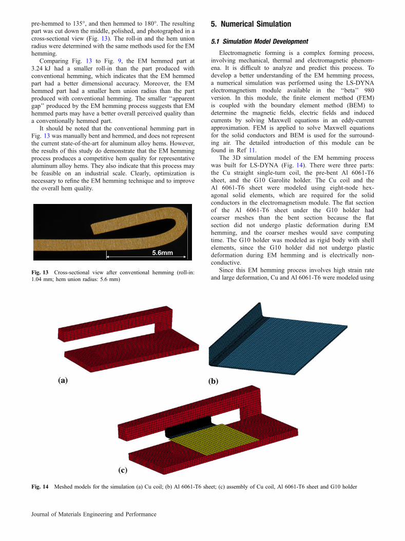
The 3D simulation model of the EM hemming processwas built for LS-DYNA (Fig. 14). There were three parts:the Cu straight single-turn coil, the pre-bent Al 6061-T6sheet, and the G10 Garolite holder. The Cu coil and theAl 6061-T6 sheet were modeled using eight-node hex-agonal solid elements, which are required for the solidconductors in the electromagnetism module. The flat sectionof the Al 6061-T6 sheet under the G10 holder hadcoarser meshes than the bent section because the flatsection did not undergo plastic deformation during EMhemming, and the coarser meshes would save computingtime. The G10 holder was modeled as rigid body with shellelements, since the G10 holder did not undergo plasticdeformation during EM hemming and is electrically non-conductive.
Since this EM hemming process involves high strain rateand large deformation, Cu and Al 6061-T6 were modeled using
Fig. 13 Cross-sectional view after conventional hemming (roll-in:1.04 mm; hem union radius: 5.6 mm)
Fig. 14 Meshed models for the simulation (a) Cu coil; (b) Al 6061-T6 sheet; (c) assembly of Cu coil, Al 6061-T6 sheet and G10 holder
Journal of Materials Engineering and Performance

the Johnson-Cook strength model, which has the followingform (Ref 12):
r ¼ ðAþ BenÞð1þ C ln _eÞ 1� T � TroomTm � Troom
� �m� �
Table 2 lists the Johnson-Cook strength model parametersfor Al 6061-T6 and Cu used in this simulation. Table 3 lists thematerial properties of Al 6061-T6 and Cu. The measuredcurrent trace in Fig. 15 was set as the input for the simulation inthe 2.7 kJ energy input case.
5.2 Comparison Between Experimental and NumericalResults
Figure 16 presents the comparison between the experimen-tal and numerical simulation results for the 2.7 kJ energy inputcase. It shows that the numerical simulation result over-estimated the EM hemming deformation. There was approxi-mately a 0.3-mm gap between the hemming edge and the topsurface of the flat section. However, the hemming edgeimpacted onto the top surface of the flat section in thenumerical simulation. One possible reason for the overestima-tion is that the part was physically bent to 90� prior to theelectromagnetic hemming. The pre-bending was not consideredin the numerical simulation. Therefore, the strain-hardeningprior to the electromagnetic hemming was not included in thenumerical simulation, which might affect the simulation result.
5.3 Lorenz Force Distribution
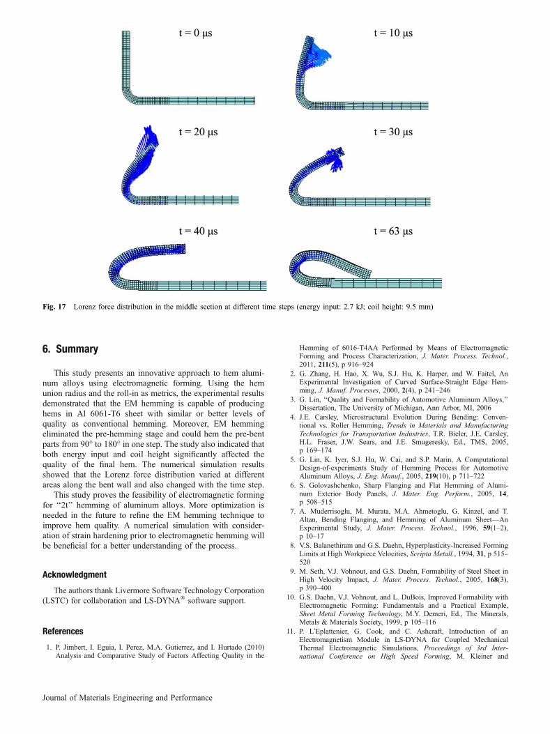
During electromagnetic forming, workpiece is acceleratedand deformed through Lorenz forces between coil and work-piece that is difficult to predict due to the complexity ofelectromagnetic forming. Lorenz forces vary over time andlocation. But accurate prediction of Lorenz forces is critical toachieve the desired deformation. The numerical simulation inthis study provided insight about the variation of Lorenz forcesduring EM hemming, which is helpful to design EM hemmingcoil and process. Figure 17 presents the Lorenz force distribu-tion in the middle section at the different time steps. At theearly stage, the repulsive Lorenz forces concentrated on theupper area of the bent wall and then moved the upper areaforward first. With the movement of the upper area, theattractive Lorenz forces occured to act on the upper area and therepulsive Lorenz forces acted on the rest of the bent wall atthe 20-ls time step. The bent wall continued to move forwardas a result of inertia. The repulsive Lorenz forces concentratedagain on the small upper area of the bent wall at the 30-ls timestep. With the increase of the gap between the bent wall and thecoil, the coupling between them became weaker and weaker. Inturn, the Lorenz forces on the bent wall became smaller andsmaller. The bent wall moved down due to inertia and impactedon the flat surface at the 63-ls time step.
Figure 17 clearly shows that the Lorenz force distributionvaried at the different areas along the bent wall and alsochanged with the time step. In addition, the Lorenz forces werelarge at the early stage, i.e., the first half cycle of the discharge.After that, the Lorenz forces became smaller and smaller.
Table 2 Johnson-Cook strength model parameters
Material A, MPa B, MPa C n m Tm, K
Al 6061-T6 (Ref 13) 324 114 0.002 0.42 1.34 925Cu (Ref 14) 90 292 0.025 0.31 1.09 1331
Table 3 Material properties of Al 6061-T6 and Cu
PropertyAl 6061-T6(Ref 15)
Cu(Ref 14)
Electrical conductivity, 106/X mm 0.0251 0.0588 (Ref 15)Mass density, g/mm3 0.0027 0.00896Young�s modulus, GPa 68.9 124Poisson�s ratio 0.33 0.34Specific heat capacity, J/g �C 0.896 0.383Thermal conductivity, W/m K 167 385 (Ref 15)
-80
-60
-40
-20
0
20
40
60
80
100
120
0 20 40 60 80 100 120 140 160
Time (µs)
Cu
rren
t (k
A)
Fig. 15 Measured current trace in the coil in 2.7 kJ case
Fig. 16 Comparison between experimental and numerical results for the case of 2.7 kJ and 9.5-mm coil height (left: experimental result; right:numerical result)
Journal of Materials Engineering and Performance
6. Summary
This study presents an innovative approach to hem alumi-num alloys using electromagnetic forming. Using the hemunion radius and the roll-in as metrics, the experimental resultsdemonstrated that the EM hemming is capable of producinghems in Al 6061-T6 sheet with similar or better levels ofquality as conventional hemming. Moreover, EM hemmingeliminated the pre-hemming stage and could hem the pre-bentparts from 90� to 180� in one step. The study also indicated thatboth energy input and coil height significantly affected thequality of the final hem. The numerical simulation resultsshowed that the Lorenz force distribution varied at differentareas along the bent wall and also changed with the time step.
This study proves the feasibility of electromagnetic formingfor ‘‘2t’’ hemming of aluminum alloys. More optimization isneeded in the future to refine the EM hemming technique toimprove hem quality. A numerical simulation with consider-ation of strain hardening prior to electromagnetic hemming willbe beneficial for a better understanding of the process.
Acknowledgment
The authors thank Livermore Software Technology Corporation(LSTC) for collaboration and LS-DYNA� software support.
References
1. P. Jimbert, I. Eguia, I. Perez, M.A. Gutierrez, and I. Hurtado (2010)Analysis and Comparative Study of Factors Affecting Quality in the
Hemming of 6016-T4AA Performed by Means of ElectromagneticForming and Process Characterization, J. Mater. Process. Technol.,2011, 211(5), p 916–924
2. G. Zhang, H. Hao, X. Wu, S.J. Hu, K. Harper, and W. Faitel, AnExperimental Investigation of Curved Surface-Straight Edge Hem-ming, J. Manuf. Processes, 2000, 2(4), p 241–246
3. G. Lin, ‘‘Quality and Formability of Automotive Aluminum Alloys,’’Dissertation, The University of Michigan, Ann Arbor, MI, 2006
4. J.E. Carsley, Microstructural Evolution During Bending: Conven-tional vs. Roller Hemming, Trends in Materials and ManufacturingTechnologies for Transportation Industries, T.R. Bieler, J.E. Carsley,H.L. Fraser, J.W. Sears, and J.E. Smugeresky, Ed., TMS, 2005,p 169–174
5. G. Lin, K. Iyer, S.J. Hu, W. Cai, and S.P. Marin, A ComputationalDesign-of-experiments Study of Hemming Process for AutomotiveAluminum Alloys, J. Eng. Manuf., 2005, 219(10), p 711–722
6. S. Golovashchenko, Sharp Flanging and Flat Hemming of Alumi-num Exterior Body Panels, J. Mater. Eng. Perform., 2005, 14,p 508–515
7. A. Muderrisoglu, M. Murata, M.A. Ahmetoglu, G. Kinzel, and T.Altan, Bending Flanging, and Hemming of Aluminum Sheet—AnExperimental Study, J. Mater. Process. Technol., 1996, 59(1–2),p 10–17
8. V.S. Balanethiram and G.S. Daehn, Hyperplasticity-Increased FormingLimits at High Workpiece Velocities, Scripta Metall., 1994, 31, p 515–520
9. M. Seth, V.J. Vohnout, and G.S. Daehn, Formability of Steel Sheet inHigh Velocity Impact, J. Mater. Process. Technol., 2005, 168(3),p 390–400
10. G.S. Daehn, V.J. Vohnout, and L. DuBois, Improved Formability withElectromagnetic Forming: Fundamentals and a Practical Example,Sheet Metal Forming Technology, M.Y. Demeri, Ed., The Minerals,Metals & Materials Society, 1999, p 105–116
11. P. L�Eplattenier, G. Cook, and C. Ashcraft, Introduction of anElectromagnetism Module in LS-DYNA for Coupled MechanicalThermal Electromagnetic Simulations, Proceedings of 3rd Inter-national Conference on High Speed Forming, M. Kleiner and
Fig. 17 Lorenz force distribution in the middle section at different time steps (energy input: 2.7 kJ; coil height: 9.5 mm)
Journal of Materials Engineering and Performance

A.E. Tekkaya, Ed., March 11–12, 2008 (Dortmund), TechnicalUniversity Dortmund, p 85–96
12. G.R. Johnson and W.H. Cook, A Constitutive Model and Data forMetals Subjected to Large Strains, High Strain Rates andHigh Temperatures, Proceedings of 7th International Sympo-sium on ballistics, April 1983, The Hague, The Netherlands,p 541–547
13. B.M. Corbett, Numerical Simulations of Target Hole Diameters forHypervelocity Impacts into Elevated and Room Temperature Bumpers,Int. J. Impact Eng., 2006, 33, p 431–440
14. G.R. Johnson and W.H. Cook, Fracture Characteristics of Three MetalsSubjected to Various Strains, Strain Rates, Temperatures and Pressures,Eng. Fract. Mech., 1985, 21, p 31–48
15. http://www.matweb.com, Accessed, October 8, 2010
Journal of Materials Engineering and Performance