Dynamic Fracture Toughness of Magnesium Alloy under Impact Loading Conditions
6
Procedia Engineering 53 (2013) 639 – 644 1877-7058 © 2013 The Authors. Published by Elsevier Ltd. Selection and peer-review under responsibility of the Research Management & Innovation Centre, Universiti Malaysia Perlis doi:10.1016/j.proeng.2013.02.082 Malaysian Technical Universities Conference on Engineering & Technology 2012, MUCET 2012 Part 2 Mechanical And Manufacturing Engineering Dynamic Fracture Toughness of Magnesium Alloy under Impact Loading Conditions Mohd Ahadlin Mohd Daud ª* , Nurulhilmi Zaedah Nasir ª , Ahmad Rivai ª and Mohd Zulkefli Selamat ª * Faculty of Mechanical Engineering, Universiti Teknikal Malaysia Melaka, Melaka, Malaysia Abstract In the present study, three-point bend impact experiments on AZ61 magnesium alloy were conducted using an instrumented impact testing machine by Charpy V notch in accordance to ASTM E24.03.03. This test method is to determine dynamic fracture toughness at sharp crack for five different thickness of 2, 4, 6, 8 and 10 mm. A sharp fatigue pre-crack was initiated and propagated to half of specimen width at a constant crack propagation rate of about 1 x 10 -8 m/cycle before the specimen was loaded by the impact force until the maximum force is reached and then rapid fracture occurred. The Charpy V notch test was conducted at an impact velocity of 3.85 m/s. The dynamics fracture toughness at sharp crack was determined from the force-displacement history of the load point obtained from measurements of input and reflected strain profiles on the incident specimen. The dynamic fracture toughness K d values obtained for different thicknesses showed that K d value decreased with increasing specimen thickness. Scanning electron microscopy was used to elucidate the micro and macro failure mechanism operation during the dynamic fracture event. In particular two micro-mechanisms of failure were of primary interest: (a) fatigue and rapid fracture surface and (b) the development of shear lips at the surface of the specimen follow by fracture. Keywords: Dynamic fracture toughness, impact loading, Charpy impact test, AZ61 magnesium alloy 1. Introduction Magnesium alloy is a lightweight and high specific strength compared to aluminium and titanium. It has found increasing use in several key engineering such as cases, housings, brackets, panel, etc. The major application benefit is the weight reduction due to their low density which consequently lead to fuel saving. Other advantages of magnesium alloy are high specific strength, good in casting, machining and recyclability. Recently more demanding application where resistance to impact is of critical importance, e.g. as light weight body aerospace and automobile [1,2]. It is an important topic of research for material science when fracture properties of materials processed under the form of plates must be characterized, and for structural mechanics when the integrity of structures made of different thickness plates must be assessed [3]. And furthermore, it has been found that fracture properties as compared to elastic and plastic material properties, depends on the specimen size, crack depth, geometry and loading conditions [4-6]. * Corresponding author.E-mail address: [email protected] Available online at www.sciencedirect.com © 2013 The Authors. Published by Elsevier Ltd. Selection and peer-review under responsibility of the Research Management & Innovation Centre, Universiti Malaysia Perlis
-
Upload
independent -
Category
Documents
-
view
0 -
download
0
Transcript of Dynamic Fracture Toughness of Magnesium Alloy under Impact Loading Conditions
Procedia Engineering 53 ( 2013 ) 639 – 644
1877-7058 © 2013 The Authors. Published by Elsevier Ltd.Selection and peer-review under responsibility of the Research Management & Innovation Centre, Universiti Malaysia Perlisdoi: 10.1016/j.proeng.2013.02.082
Malaysian Technical Universities Conference on Engineering & Technology 2012, MUCET 2012 Part 2 Mechanical And Manufacturing Engineering
Dynamic Fracture Toughness of Magnesium Alloy under Impact Loading Conditions
Mohd Ahadlin Mohd Daudª*, Nurulhilmi Zaedah Nasirª, Ahmad Rivaiª and Mohd Zulkefli Selamatª
*Faculty of Mechanical Engineering, Universiti Teknikal Malaysia Melaka,
Melaka, Malaysia
Abstract
In the present study, three-point bend impact experiments on AZ61 magnesium alloy were conducted using an instrumented impact testing machine by Charpy V notch in accordance to ASTM E24.03.03. This test method is to determine dynamic fracture toughness at sharp crack for five different thickness of 2, 4, 6, 8 and 10 mm. A sharp fatigue pre-crack was initiated and propagated to half of specimen width at a constant crack propagation rate of about 1 x 10⁻⁸ m/cycle before the specimen was loaded by the impact force until the maximum force is reached and then rapid fracture occurred. The Charpy V notch test was conducted at an impact velocity of 3.85 m/s. The dynamics fracture toughness at sharp crack was determined from the force-displacement history of the load point obtained from measurements of input and reflected strain profiles on the incident specimen. The dynamic fracture toughness Kd values obtained for different thicknesses showed that Kd value decreased with increasing specimen thickness. Scanning electron microscopy was used to elucidate the micro and macro failure mechanism operation during the dynamic fracture event. In particular two micro-mechanisms of failure were of primary interest: (a) fatigue and rapid fracture surface and (b) the development of shear lips at the surface of the specimen follow by fracture. © 2013 The Authors. Published by Elsevier Ltd. Selection and/or peer-review under responsibility of the Research Management & Innovation Centre, Universiti Malaysia Perlis. Keywords: Dynamic fracture toughness, impact loading, Charpy impact test, AZ61 magnesium alloy
1. Introduction
Magnesium alloy is a lightweight and high specific strength compared to aluminium and titanium. It has found increasing use in several key engineering such as cases, housings, brackets, panel, etc. The major application benefit is the weight reduction due to their low density which consequently lead to fuel saving. Other advantages of magnesium alloy are high specific strength, good in casting, machining and recyclability. Recently more demanding application where resistance to impact is of critical importance, e.g. as light weight body aerospace and automobile [1,2].
It is an important topic of research for material science when fracture properties of materials processed under the form of plates must be characterized, and for structural mechanics when the integrity of structures made of different thickness plates must be assessed [3]. And furthermore, it has been found that fracture properties as compared to elastic and plastic material properties, depends on the specimen size, crack depth, geometry and loading conditions [4-6].
* Corresponding author.E-mail address: [email protected]
Available online at www.sciencedirect.com
© 2013 The Authors. Published by Elsevier Ltd.Selection and peer-review under responsibility of the Research Management & Innovation Centre, Universiti Malaysia Perlis
640 Mohd Ahadlin Mohd Daud et al. / Procedia Engineering 53 ( 2013 ) 639 – 644
Visual examination of fracture surface subsequent to testing is an important step in determining the effect of thickness on fracture toughness of structural materials. The morphology of the fracture surface can vary from flat surface when the resistance to crack propagation is low (as is the case for a transgranular cleavage) to a surface which has developed varying widths of oblique shear lips when resistance to crack propagation is high. In many fracture test such as the Charpy V notch (Cv) [7], dynamic tear (DT)[8] and drop weight test (DWTT)[9], measurement of percentage shear which is somewhat related to shear lip size is the basic physical measurement required.
The objective of this study is to determine the dynamic fracture toughness for extruded AZ61 magnesium alloy with various thickness specimens.
2. Methodology
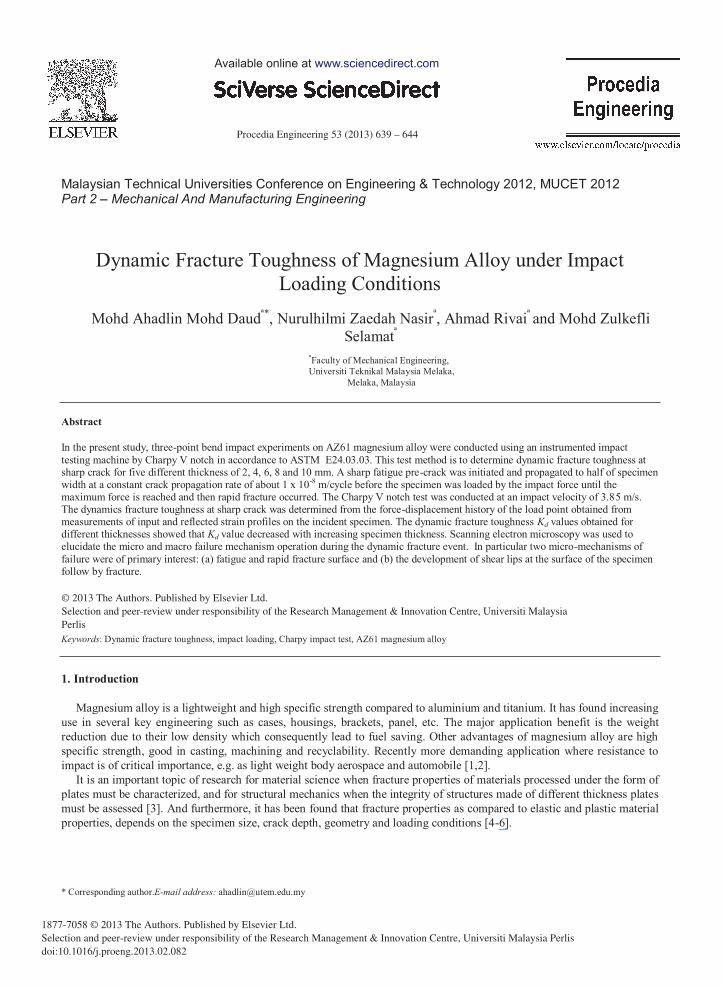
The specimen used for dynamics fracture toughness test was single edge notch bend (SENB or 3 point bending) specimen as shown in Fig. 1. Specimen geometry was selected according to ASTM E399 standard [10]. The specimen was then polished with 500 to 1500 grit emery papers to obtain smooth surface. The pre-cracking was attained at pre-cracking growth rates less than 10-8 m/cycle until the crack reaches half of the width of the specimen. Pre-cracking was carried out on a pneumatic fatigue testing machine (14 kN maximum capacity). The pre-cracking were performed at frequencies 10 Hz and using sinusoidal loading form. Stress ratio R=0.1 was applied in pre-cracking procedure at room temperature. The pre-cracking was performed at a constant level to obtain constant crack growth rate.
According to ASTM E24.03.03 [11] the dynamic fracture toughness, Kd can be calculated from the critical value of load i.e. from the load measured just at the beginning of unstable fracture, using the conventional expression derived for the static stress intensity factor. The approach by ASTM E24.03.03 for metals consists of determination the maximum force Fm, maximum displacement sm and the time which elapses, tm . If Fm is assumed to be identical with Pmax as the force which indicates the beginning of unstable crack propagation the dynamic fracture toughness, Kd assuming a linear-elastic behavior can be represented as:
Waf
BWSPK d 2/3
max
(1)
Geometrical factor,
2/92/72/52/32/1 7.386.378.216.49.2Waf
(2)
Here, P = load, [N], S = span length, [40 mm], B = specimen thickness, [mm], W = specimen width, [10 mm] and a = crack length, [mm].
The impact testing was performed after the fatigue pre-crack to obtain the value of dynamic fracture toughness, Kd. The test was conducted at room temperature using an instrumented impact testing machine equipped with a personal computer. The single edge notch bend (SENB) specimen with 5 mm crack was placed at the mounting with the pendulum speeds 3.85 m/s.
Fig. 1. Geometry of the SENB specimen used in fracture test as per ASTM.
60
30 mm
10 mm
45o
1.25 mm 5 mm
641 Mohd Ahadlin Mohd Daud et al. / Procedia Engineering 53 ( 2013 ) 639 – 644
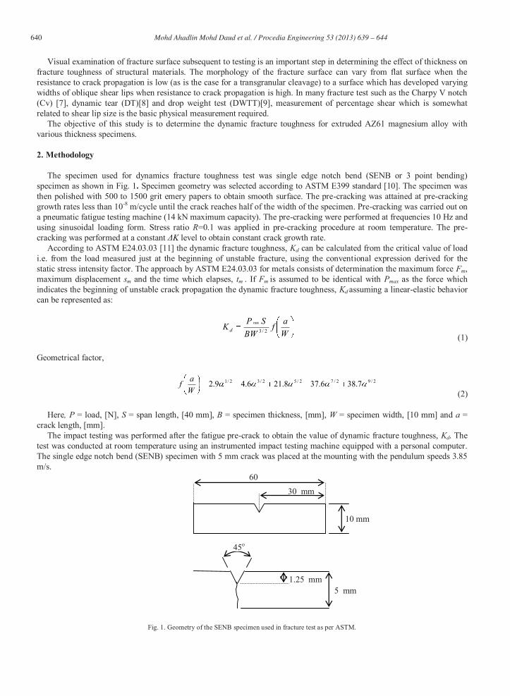
Macroscopic observation of fracture surfaces of the specimens clearly showed two discrete regions. These two distinct
regions are shown in the optical micrograph of Fig. 3. The boundaries of these regions are well distinguished between the fatigue fracture region and dynamic fracture region. The direction of the crack propagation was clearly determined. The fatigue crack initiated from the notch and propagated parallel on both side. The fatigue fracture region indicated the gradual crack propagation due to fatigue while the dynamic fracture region with shinning appearance shows the unstable crack propagation and characterized by fast crack features.
Figure 2: Overview fracture surface after impact test for 2, 4, 6, 8 and 10 mm thickness
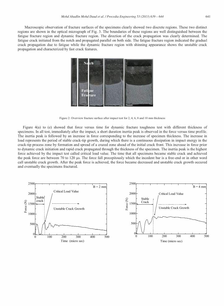
Figure 4(a) to (e) showed that force versus time for dynamic fracture toughness test with different thickness of specimens. In all test, immediately after the impact, a short duration inertia peak is observed in the force versus time profile. The inertia peak is followed by an increase in force corresponding to the increase of specimen thickness. The increase in load represents the period of stable crack-tip growth, during which there is a continuous dissipation in impact energy in the crack-tip process zone by formation and spread of a crazed zone ahead of the initial crack front. This increase in force prior to dynamic crack initiation and rapid crack propagated through the thickness of the specimen. The inertia peak is the highest force achieved by the impact test called critical load value. The time that all specimens became stable crack and achieved the peak force are between 70 to 120 μs. The force fall precepitously which the incedent bar is a free-end or in other word call unstable crack growth. After the peak force is achieved, the force became decreased and unstable crack growth occured and eventually the specimens fractured.
0 100 200 300 400 5000
500
1000
1500
2000
2500
Time (micro sec)
Forc
e (N
)
Critical Load Value
Unstable Crack Growth
Stablecrack
B = 2 mm
0 100 200 300 400 5000
500
1000
1500
2000
2500
Time (micro sec)
Forc
e (N
) Stable Crack
Unstable Crack Growth
Critical Load Value
B = 4 mm
Notch
Fatigue Fracture
Dynamic Fracture
642 Mohd Ahadlin Mohd Daud et al. / Procedia Engineering 53 ( 2013 ) 639 – 644
0 100 200 300 400 5000
500
1000
1500
2000
2500Fo
rce
(N)
Time (micro sec)
Stable Crack
Critical Load value
Unstable Crack Growth
B = 6 mm
0 100 200 300 400 5000
500
1000
1500
2000
2500
Forc
e (N
)
Time (micro sec)
StableCrack
Critical Load Value
Unstable Crack Growth
B = 8 mm
0 100 200 300 400 5000
500
1000
1500
2000
2500
Forc
e (N
)
Time (micro sec)
B = 10 mmStable Crack Critical Load Value
Unstable Crack Growth
Fig. 3. Force versus time for specimen thickness of 2, 4, 6, 8, and 10 mm.
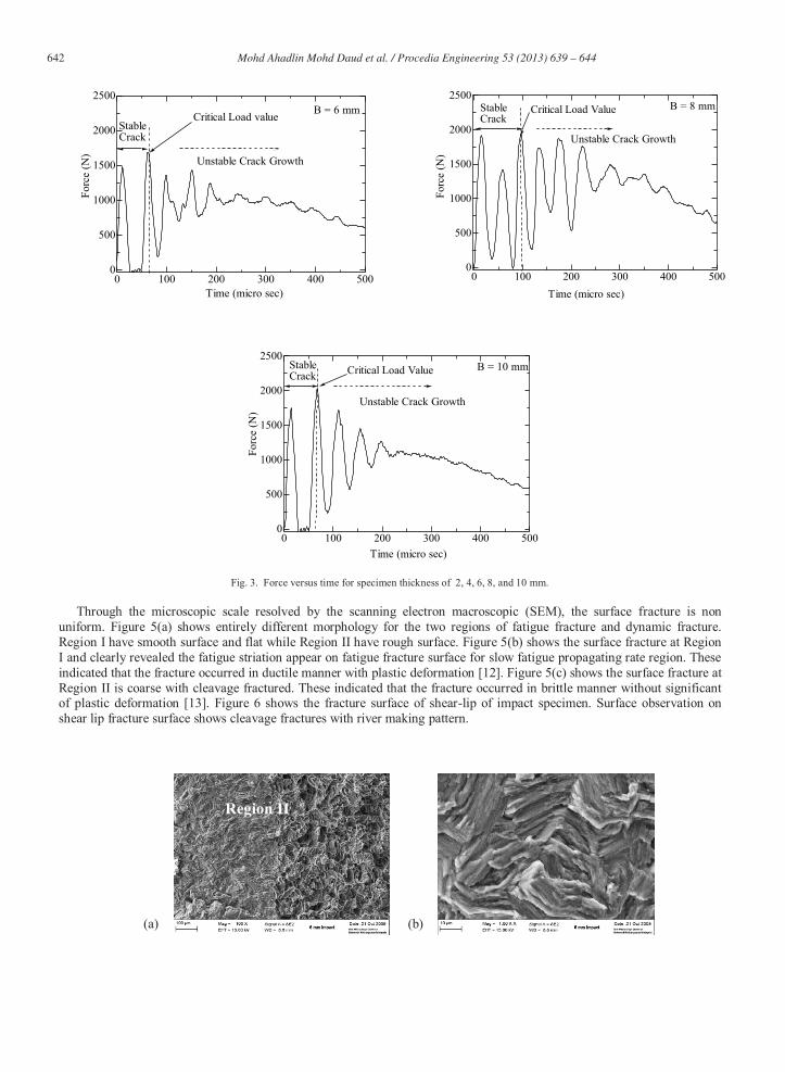
Through the microscopic scale resolved by the scanning electron macroscopic (SEM), the surface fracture is non
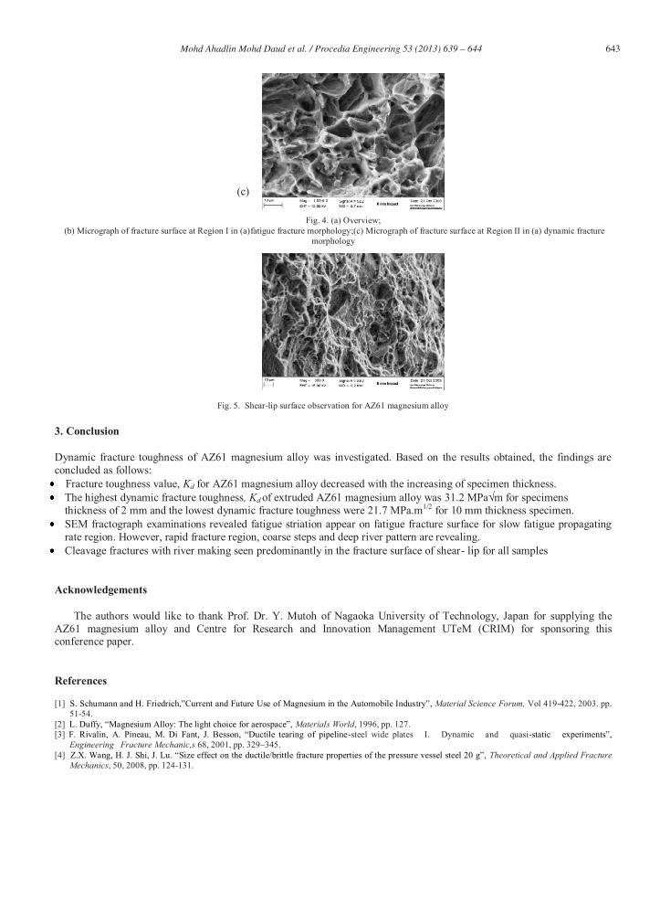
uniform. Figure 5(a) shows entirely different morphology for the two regions of fatigue fracture and dynamic fracture. Region I have smooth surface and flat while Region II have rough surface. Figure 5(b) shows the surface fracture at Region I and clearly revealed the fatigue striation appear on fatigue fracture surface for slow fatigue propagating rate region. These indicated that the fracture occurred in ductile manner with plastic deformation [12]. Figure 5(c) shows the surface fracture at Region II is coarse with cleavage fractured. These indicated that the fracture occurred in brittle manner without significant of plastic deformation [13]. Figure 6 shows the fracture surface of shear-lip of impact specimen. Surface observation on shear lip fracture surface shows cleavage fractures with river making pattern.
Region II Region I
(b) (a)
643 Mohd Ahadlin Mohd Daud et al. / Procedia Engineering 53 ( 2013 ) 639 – 644
Fig. 4. (a) Overview; (b) Micrograph of fracture surface at Region I in (a)fatigue fracture morphology;(c) Micrograph of fracture surface at Region II in (a) dynamic fracture
morphology
Fig. 5. Shear-lip surface observation for AZ61 magnesium alloy
3. Conclusion
Dynamic fracture toughness of AZ61 magnesium alloy was investigated. Based on the results obtained, the findings are concluded as follows: Fracture toughness value, Kd for AZ61 magnesium alloy decreased with the increasing of specimen thickness. The highest dynamic fracture toughness, Kd of extruded AZ61 magnesium alloy was 31.2 MPa m for specimens
thickness of 2 mm and the lowest dynamic fracture toughness were 21.7 MPa.m1/2 for 10 mm thickness specimen. SEM fractograph examinations revealed fatigue striation appear on fatigue fracture surface for slow fatigue propagating
rate region. However, rapid fracture region, coarse steps and deep river pattern are revealing. Cleavage fractures with river making seen predominantly in the fracture surface of shear- lip for all samples
Acknowledgements
The authors would like to thank Prof. Dr. Y. Mutoh of Nagaoka University of Technology, Japan for supplying the AZ61 magnesium alloy and Centre for Research and Innovation Management UTeM (CRIM) for sponsoring this conference paper.
References
[1] Material Science Forum, Vol 419-422, 2003. pp. 51-54.
[2] Materials World, 1996, pp. 127. [3] -steel wide plates I. Dynamic and quasi-
Engineering Fracture Mechanic,s 68, 2001, pp. 329 345. [4] Theoretical and Applied Fracture
Mechanics, 50, 2008, pp. 124-131.
(c)

644 Mohd Ahadlin Mohd Daud et al. / Procedia Engineering 53 ( 2013 ) 639 – 644
[5] Int. Journal of Impact Engineering, 30, 2004, pp. 957-971.
[6] J. R. Matthews, C. V. Hyatt, J.F. Porter. Effect of thickness on the relationship between shear lip and energy in dynamic tear specimens. Engineering Fracture Mechanics Vol. 60, No 5-6,(1998) 529-542.
[7] Am. Soc. Test. Mater. Philadelphia, PA, U.S.A. 2008. [8] Am. Soc. Test. Mater. Philadelphia, PA, U.S.A.2008. [9] - Am. Soc. Test. Mater. Philadelphia, PA, U.S.A.2008. [10] ASTM E399- KIC of Metallic Materials, 2008. [11]ASTM E 24.03.03. Proposed standard method of test for instrumented impact testing of precracked charpy-specimens of metallic materials, 1980. [12] nd ed., CRC Press: Boca Raton, New York. 2005. [13] -Ca- Material Science and Eng. A. 54, 2007,
pp. 366-370..