Heat transfer augmentation in a two-sided lid-driven differentially heated square cavity utilizing...
17
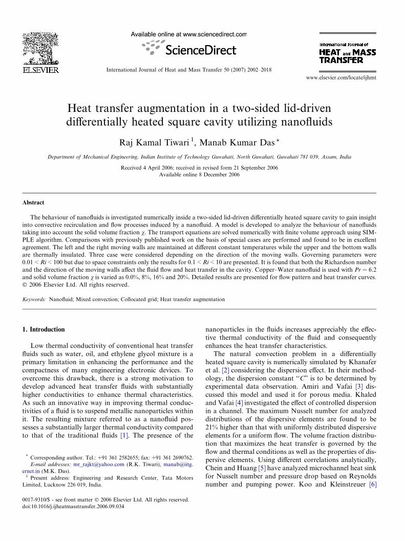
Heat transfer augmentation in a two-sided lid-driven differentially heated square cavity utilizing nanofluids Raj Kamal Tiwari 1 , Manab Kumar Das * Department of Mechanical Engineering, Indian Institute of Technology Guwahati, North Guwahati, Guwahati 781 039, Assam, India Received 4 April 2006; received in revised form 21 September 2006 Available online 8 December 2006 Abstract The behaviour of nanofluids is investigated numerically inside a two-sided lid-driven differentially heated square cavity to gain insight into convective recirculation and flow processes induced by a nanofluid. A model is developed to analyze the behaviour of nanofluids taking into account the solid volume fraction v. The transport equations are solved numerically with finite volume approach using SIM- PLE algorithm. Comparisons with previously published work on the basis of special cases are performed and found to be in excellent agreement. The left and the right moving walls are maintained at different constant temperatures while the upper and the bottom walls are thermally insulated. Three case were considered depending on the direction of the moving walls. Governing parameters were 0.01 < Ri < 100 but due to space constraints only the results for 0.1 < Ri < 10 are presented. It is found that both the Richardson number and the direction of the moving walls affect the fluid flow and heat transfer in the cavity. Copper–Water nanofluid is used with Pr = 6.2 and solid volume fraction v is varied as 0.0%, 8%, 16% and 20%. Detailed results are presented for flow pattern and heat transfer curves. Ó 2006 Elsevier Ltd. All rights reserved. Keywords: Nanofluid; Mixed convection; Collocated grid; Heat transfer augmentation 1. Introduction Low thermal conductivity of conventional heat transfer fluids such as water, oil, and ethylene glycol mixture is a primary limitation in enhancing the performance and the compactness of many engineering electronic devices. To overcome this drawback, there is a strong motivation to develop advanced heat transfer fluids with substantially higher conductivities to enhance thermal characteristics. As such an innovative way in improving thermal conduc- tivities of a fluid is to suspend metallic nanoparticles within it. The resulting mixture referred to as a nanofluid pos- sesses a substantially larger thermal conductivity compared to that of the traditional fluids [1]. The presence of the nanoparticles in the fluids increases appreciably the effec- tive thermal conductivity of the fluid and consequently enhances the heat transfer characteristics. The natural convection problem in a differentially heated square cavity is numerically simulated by Khanafer et al. [2] considering the dispersion effect. In their method- ology, the dispersion constant ‘‘C” is to be determined by experimental data observation. Amiri and Vafai [3] dis- cussed this model and used it for porous media. Khaled and Vafai [4] investigated the effect of controlled dispersion in a channel. The maximum Nusselt number for analyzed distributions of the dispersive elements are found to be 21% higher than that with uniformly distributed dispersive elements for a uniform flow. The volume fraction distribu- tion that maximizes the heat transfer is governed by the flow and thermal conditions as well as the properties of dis- persive elements. Using different correlations analytically, Chein and Huang [5] have analyzed microchannel heat sink for Nusselt number and pressure drop based on Reynolds number and pumping power. Koo and Kleinstreuer [6] 0017-9310/$ - see front matter Ó 2006 Elsevier Ltd. All rights reserved. doi:10.1016/j.ijheatmasstransfer.2006.09.034 * Corresponding author. Tel.: +91 361 2582655; fax: +91 361 2690762. E-mail addresses: [email protected] (R.K. Tiwari), manab@iitg. ernet.in (M.K. Das). 1 Present address: Engineering and Research Center, Tata Motors Limited, Lucknow 226 019, India. www.elsevier.com/locate/ijhmt International Journal of Heat and Mass Transfer 50 (2007) 2002–2018
-
Upload
independent -
Category
Documents
-
view
5 -
download
0
Transcript of Heat transfer augmentation in a two-sided lid-driven differentially heated square cavity utilizing...
www.elsevier.com/locate/ijhmt
International Journal of Heat and Mass Transfer 50 (2007) 2002–2018
Heat transfer augmentation in a two-sided lid-drivendifferentially heated square cavity utilizing nanofluids
Raj Kamal Tiwari 1, Manab Kumar Das *
Department of Mechanical Engineering, Indian Institute of Technology Guwahati, North Guwahati, Guwahati 781 039, Assam, India
Received 4 April 2006; received in revised form 21 September 2006Available online 8 December 2006
Abstract
The behaviour of nanofluids is investigated numerically inside a two-sided lid-driven differentially heated square cavity to gain insightinto convective recirculation and flow processes induced by a nanofluid. A model is developed to analyze the behaviour of nanofluidstaking into account the solid volume fraction v. The transport equations are solved numerically with finite volume approach using SIM-PLE algorithm. Comparisons with previously published work on the basis of special cases are performed and found to be in excellentagreement. The left and the right moving walls are maintained at different constant temperatures while the upper and the bottom wallsare thermally insulated. Three case were considered depending on the direction of the moving walls. Governing parameters were0.01 < Ri < 100 but due to space constraints only the results for 0.1 < Ri < 10 are presented. It is found that both the Richardson numberand the direction of the moving walls affect the fluid flow and heat transfer in the cavity. Copper–Water nanofluid is used with Pr = 6.2and solid volume fraction v is varied as 0.0%, 8%, 16% and 20%. Detailed results are presented for flow pattern and heat transfer curves.� 2006 Elsevier Ltd. All rights reserved.
Keywords: Nanofluid; Mixed convection; Collocated grid; Heat transfer augmentation
1. Introduction
Low thermal conductivity of conventional heat transferfluids such as water, oil, and ethylene glycol mixture is aprimary limitation in enhancing the performance and thecompactness of many engineering electronic devices. Toovercome this drawback, there is a strong motivation todevelop advanced heat transfer fluids with substantiallyhigher conductivities to enhance thermal characteristics.As such an innovative way in improving thermal conduc-tivities of a fluid is to suspend metallic nanoparticles withinit. The resulting mixture referred to as a nanofluid pos-sesses a substantially larger thermal conductivity comparedto that of the traditional fluids [1]. The presence of the
0017-9310/$ - see front matter � 2006 Elsevier Ltd. All rights reserved.
doi:10.1016/j.ijheatmasstransfer.2006.09.034
* Corresponding author. Tel.: +91 361 2582655; fax: +91 361 2690762.E-mail addresses: [email protected] (R.K. Tiwari), manab@iitg.
ernet.in (M.K. Das).1 Present address: Engineering and Research Center, Tata Motors
Limited, Lucknow 226 019, India.
nanoparticles in the fluids increases appreciably the effec-tive thermal conductivity of the fluid and consequentlyenhances the heat transfer characteristics.
The natural convection problem in a differentiallyheated square cavity is numerically simulated by Khanaferet al. [2] considering the dispersion effect. In their method-ology, the dispersion constant ‘‘C” is to be determined byexperimental data observation. Amiri and Vafai [3] dis-cussed this model and used it for porous media. Khaledand Vafai [4] investigated the effect of controlled dispersionin a channel. The maximum Nusselt number for analyzeddistributions of the dispersive elements are found to be21% higher than that with uniformly distributed dispersiveelements for a uniform flow. The volume fraction distribu-tion that maximizes the heat transfer is governed by theflow and thermal conditions as well as the properties of dis-persive elements. Using different correlations analytically,Chein and Huang [5] have analyzed microchannel heat sinkfor Nusselt number and pressure drop based on Reynoldsnumber and pumping power. Koo and Kleinstreuer [6]
Nomenclature
i x-direction grid pointj y-direction grid pointkf thermal conductivity of the fluid, W/m Kks thermal conductivity of the solid, W/m KNu local Nusselt numberNu average Nusselt numbern time levelPr Prandtl number,
mf
af
Re Reynolds number for the fluidt* dimensional time, st non-dimensional timeu*, v* dimensional velocity components along (x*,y*)
axes, m/su, v dimensionless velocity components along (x,y)
axesVp velocity of the moving lid, m/s
x*, y* dimensional Cartesian co-ordinates, mx, y dimensionless Cartesian co-ordinates
Greek symbols
a thermal diffusivity, m2/sbf fluid thermal expansion coefficient
bs solid expansion coefficiente convergence criterionj excess thermal-conductivity enhancement coeffi-
cientm kinematic viscosity, m2/sv solid volume fraction
Subscripts
c cold walleff effectivef fluidh hot wallnf nanofluid0 reference values solid
Superscript* dimensional term
R.K. Tiwari, M.K. Das / International Journal of Heat and Mass Transfer 50 (2007) 2002–2018 2003
have used Brownian motion based-thermal conductivityand viscosity to numerically simulate the microheat sink.Additionally they considered the viscous dissipation term.They suggested that a high-Prandtl number base fluidand a high aspect ratio channel should be used for betterheat transfer performance. Roy et al. [7] has consideredthe case of radial flow cooling system for numerical simu-lation. For physical properties calculation they obtaineda correlations by curve fitting on the experimental dataand found that nanofluids increased the wall shear stressin a considerable way. Maiga et al. [8] have numericallysimulated nanofluid behaviour in a uniformly heated tubefor laminar as well as turbulent flow using approximatedcorrelations for experimental data. They found that for tur-bulent flow regime, the heat transfer enhancement due tonanoparticles becomes more important with the increaseof the Reynolds number. In another study, Maiga et al.[9] numerically simulated nanofluids in forced convectionflows and solved the problems of uniformly heated tubeand a system of parallel, coaxial and heated disks. Theyfound that both the through flow Reynolds number andthe gap between disks have insignificant effect on the heattransfer enhancement of nanofluids.
Fluid flow and heat transfer in a rectangular or a squarecavity driven by buoyancy and shear have been studiedextensively in the literature [10,11]. Mixed convection prob-lem with lid-driven flows in enclosures are encountered in avariety of engineering applications including cooling ofelectronic devices, furnaces, lubrication technologies,
chemical processing equipment, drying technologies, etc.Combination of buoyancy forces due to temperature gradi-ent and forced convection due to shear results in a mixedconvection heat transfer, which is a complex phenomenondue to the interaction of these forces.
To investigate the heat transfer enhancement by veryfine particles suspended in a fluid, two main approacheshave been adopted in the literature. The first one is thetwo-phase model that takes into account the fluid and solidphase role in the heat transfer process. The second one isthe single-phase model where both the fluid phase andthe solid particles are in thermal equilibrium state and flowwith the same local velocity. Several issues are involvedwhile studying the heat transfer enhancement utilizingnanofluids. These issues are like gravity, Brownian motion,layering at the interface between solid and liquid, clusteringof the nanoparticles, ballistic phono transport through theparticles and the friction between the fluid and the solidparticles. The phenomena of sedimentation, dispersionand Brownian diffusion may coexist in the main flow of ananofluid. In the absence of any suitable theoretical studiesand experimental data in the literature to investigate theseissues, the existing macroscopic two-phase model is notapplicable for analyzing nanofluids [2,12]. If the main inter-est is focused on the heat transfer process, the modified sin-gle-phase, accounting for some of the above factors, ismore convenient than the two-phase model. Also, the supe-rior characteristics of the nanofluid allow it to behave morelike a fluid rather than the conventional solid–fluid
2004 R.K. Tiwari, M.K. Das / International Journal of Heat and Mass Transfer 50 (2007) 2002–2018
mixtures. Modeling the effective thermal conductivity posesa challenge while studying the heat transfer enhancementusing nanofluids. Maxwell’s model [13] predicted that theeffective thermal conductivity of suspensions containingspherical particles increases with an increase in the volumefraction of the solid particles. Hamilton and Crosser [14]developed an expression for the effective thermal conduc-tivity of two-component mixtures taking into considerationthe liquid and solid particle thermal conductivities, particlevolume fraction and an empirical scaling factor to accountfor the different shapes of the particles.
Although prospects of nanofluids is very promising,there is still a dearth of enough research. To the bestknowledge of the authors, the problem of heat transferenhancement in a two-sided lid-driven differentially heatedsquare cavity filled with nanofluids has not been analyzed.This problem may be encountered in a number of elec-tronic cooling and MEMS applications. The present studyis focussed on the analysis of several pertinent parameterson the heat transfer characteristics of nanofluids withinthe enclosure. In the present study, a time marching incom-pressible flow solver has been applied for simulating theflow features of nanofluids for a range of solid volume frac-tion (v) values and Richardson number (Ri).
2. Mathematical formulation
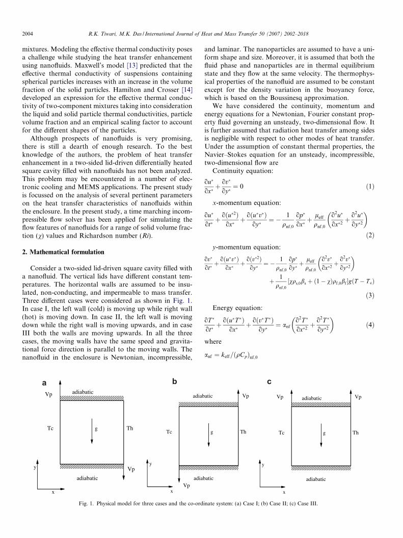
Consider a two-sided lid-driven square cavity filled witha nanofluid. The vertical lids have different constant tem-peratures. The horizontal walls are assumed to be insu-lated, non-conducting, and impermeable to mass transfer.Three different cases were considered as shown in Fig. 1.In case I, the left wall (cold) is moving up while right wall(hot) is moving down. In case II, the left wall is movingdown while the right wall is moving upwards, and in caseIII both the walls are moving upwards. In all the threecases, the moving walls have the same speed and gravita-tional force direction is parallel to the moving walls. Thenanofluid in the enclosure is Newtonian, incompressible,
Th
Vpy
x
Vp adiabatic
adiabatic
Tc g
a b
x
adiab
adia
Tc
Vp
y
Fig. 1. Physical model for three cases and the co-ord
and laminar. The nanoparticles are assumed to have a uni-form shape and size. Moreover, it is assumed that both thefluid phase and nanoparticles are in thermal equilibriumstate and they flow at the same velocity. The thermophys-ical properties of the nanofluid are assumed to be constantexcept for the density variation in the buoyancy force,which is based on the Boussinesq approximation.
We have considered the continuity, momentum andenergy equations for a Newtonian, Fourier constant prop-erty fluid governing an unsteady, two-dimensional flow. Itis further assumed that radiation heat transfer among sidesis negligible with respect to other modes of heat transfer.Under the assumption of constant thermal properties, theNavier–Stokes equation for an unsteady, incompressible,two-dimensional flow are
Continuity equation:
ou�
ox�þ ov�
oy�¼ 0 ð1Þ
x-momentum equation:
ou�
ot�þ oðu�2Þ
ox�þ oðu�v�Þ
oy�¼ � 1
qnf;0
op�
ox�þ leff
qnf ;0
o2u�
ox�2þ o2u�
oy�2
� �
ð2Þy-momentum equation:
ov�
ot�þ oðu�v�Þ
ox�þ oðv�2Þ
oy�¼ � 1
qnf ;0
op�
oy�þ leff
qnf ;0
o2v�
ox�2þ o2v�
oy�2
� �
þ 1
qnf ;0
½vqs;0bs þ ð1� vÞqf ;0bf �gðT � T cÞ
ð3Þ
Energy equation:
oT �
ot�þ oðu�T �Þ
ox�þ oðv�T �Þ
oy�¼ anf
o2T �
ox�2þ o2T �
oy�2
� �ð4Þ
where
anf ¼ keff=ðqCpÞnf ;0
c
Th
atic
batic
g
Vp
Th
x
adiabatic
adiabatic
Tc g
Vp
y
Vp
inate system: (a) Case I; (b) Case II; (c) Case III.
R.K. Tiwari, M.K. Das / International Journal of Heat and Mass Transfer 50 (2007) 2002–2018 2005
The viscosity of the nanofluid can be estimated with theexisting relations for the two-phase mixture. The equationgiven by Brinkman [15] has been used as the relation foreffective viscosity in this problem, as given by
leff ¼lf
ð1� vÞ2:5ð5Þ
Xuan and Li [16] have experimentally measured the appar-ent viscosity of the transformer oil–water nanofluid and ofthe water–copper nanofluid in the temperature range of 20–50 �C. The experimental results reveal relatively goodagreement with Brinkman’s theory.
The effective density of the nanofluid at reference tem-perature is
qnf ;0 ¼ ð1� vÞqf ;0 þ vqs;0 ð6Þ
and the heat capacitance of nanofluid is
ðqCpÞnf ¼ ð1� vÞðqCpÞf þ vðqCpÞs ð7Þ
as given by Xuan and Li [17]. The effective thermal conduc-tivity of fluid can be determined by Maxwell–Garnett’s(MG model) self-consistent approximation model. Forthe two-component entity of spherical-particle suspension,the MG model gives
keff
kf
¼ ðks þ 2kfÞ � 2vðkf � ksÞðks þ 2kfÞ þ vðkf � ksÞ
ð8Þ
In the absence of any convenient formula, the calcula-tion of effective thermal conductivity can be obtained fromthe above equation. For further analysis, it is convenient tointroduce the excess thermal-conductivity enhancementcoefficient j, defined as
j ¼ keff � kf
kHC � kf
ð9Þ
In the above definition, j is simply the ratio of measuredthermal conductivity increase divided by the increase pre-dicted by the Hamilton–Crosser (HC) theory. Conse-quently, j = 1 indicates agreement with the macroscopictheory, and j > 1 measures the magnitude of thermal-conductivity enhancement. The above equations can beconverted to non-dimensional form, using the followingdimensionless parameters:
x ¼ x�
H; y ¼ y�
H; u ¼ u�
V p
; v ¼ v�
V p
;
p ¼ p�
ðqV 2pÞ; T ¼ T � � T �c
DT �;
Gr ¼ gbH 3DT �
m2f
; Re ¼ V pHmf
; Pr ¼ mf
af
The governing equations can now be written in dimension-less form as follows:
Continuity equation:
ouoxþ ov
oy¼ 0 ð10Þ
x-momentum equation:
ouotþ oðu2Þ
oxþ oðuvÞ
oy¼ �
qf ;0
qnf;0
opoxþ 1
mf � Releff
qnf;0
o2u
ox2þ o
2uoy2
� �
ð11Þ
y-momentum equation:
ovotþ oðuvÞ
oxþ ov2
oy¼ �
qf ;0
qnf ;0
opoyþ 1
mf � Releff
qnf ;0
o2vox2þ o2v
oy2
� �
þ vqsbs þ ð1� vÞqfbf
bfqnf ;0
RiT ð12Þ
Energy equation:
oTotþ oðuT Þ
oxþ oðvT Þ
oy¼ anf
af
1
Pr � Reo
2Tox2þ o
2Toy2
� �ð13Þ
Boundary conditions are isothermal on the verticalmoving lids and adiabatic on the horizontal walls. On thehorizontal walls, u and v velocities are zero and the lidshave a constant velocity. The relevant boundary conditionsare given as follows:
u ¼ 0; v ¼ 1 or ðv ¼ �1Þ for x ¼ 0 and 0 6 y 6 1
u ¼ 0; v ¼ 1 or ðv ¼ �1Þ and T ¼ 1:0
for x ¼ 1 and 0 6 y 6 1
u ¼ v ¼ 0 andoToy¼ 0 for y ¼ 0 and 0 6 x 6 1
u ¼ v ¼ 0 andoToy¼ 0 for y ¼ 1 and 0 6 x 6 1
ð14Þ
The Nusselt number of the nanofluids is expected todepend on a number of factors such as thermal conductiv-ity and heat capacitance of both the pure fluid and theultrafine particles, the volume fraction of the suspendedparticles, the flow structure and the viscosity of the nano-fluid. The local variation of the Nusselt number of thenanofluid can be expressed as
Nu ¼ QQcond;fluid
¼ �ðkeffÞstagnant
kf
oToX
ð15Þ
where
Q ¼ �ðkeffÞstagnantAoT �
ox�jx�¼0 ð16Þ
The average Nusselt number along the left wall is calcu-lated by integrating the local Nusselt number over the leftwall
Nu ¼Z 1
0
Nudy ð17Þ
3. Numerical procedure
The governing equations are discretized with a collo-cated grid arrangement of the variables following the Rhie
2006 R.K. Tiwari, M.K. Das / International Journal of Heat and Mass Transfer 50 (2007) 2002–2018
and Chow scheme [18]. The governing equations are solvednumerically by finite volume method. The semi-implicitmethod for pressure linked equation (SIMPLE) [19] is usedto couple momentum and continuity equations. The thirdorder accurate deferred QUICK scheme of Hayase et al.[20] is employed to minimize the numerical diffusion forthe convective terms for both the momentum equationsand the energy equation. The solution of the discretizedmomentum and pressure correction equation is obtainedby TDMA line-by-line method [19]. The iterative proce-dure is initiated by the solution of energy equation fol-lowed by momentum equations and is continued untilconvergence is achieved. Euclidean norm of the residualis taken as convergence criteria for each dependent variablein the entire flow field [21]. The mass balance for conver-gence was taken as 10�4. At each time step, the solutionis converged and is used in the next time step as initial con-ditions. Unconditionally stable fully implicit scheme is usedto move from nth time step to (n + 1)th time step. The glo-bal convergence criteria is taken as 10�4.
Different values of under relaxation for pressure correc-tion equation and dt are used so that a logical and con-verged solution can be achieved. At steady state, theerror reaches the asymptotic behaviour. Here it is set assum of temperature error reduced to the steady-state crite-ria e
Ximax;jmax
i;j¼1
ðT nþ1i;j � T n
i;jÞ < e ð18Þ
4. Validation of the code
To validate the developed code, a two-dimensional lid-driven square-cavity flow problem [22] has been solvedand compared. Then the present code is validated for nat-ural convection heat transfer by comparing the results of abuoyancy driven laminar heat transfer in a square cavitywith differentially heated side walls. The left wall was kepthot while the right wall was cooled. The top and bottomwalls are insulated. In the present work numerical predic-tions, using the developed algorithm, have been obtainedfor Rayleigh numbers between 103 and 106. Table 1 com-pares the results with those by de Vahl Davis [23], Marka-tos and Perikleous [24], and Hadjisophocleous et al. [25],Fusegi et al. [26] and Ha and Jung [27]. The computedresults are in very good agreement with the benchmarksolution.
Iwatsu et al. [10] have solved a mixed convection prob-lem in a square cavity. The top wall is moving with a veloc-ity and maintained at hot condition. The bottom wall iscooled whereas the two vertical walls are under adiabaticcondition. The comparison of the results obtained fromthe present code with those of Iwatsu et al. [10] is shownin Table 2.
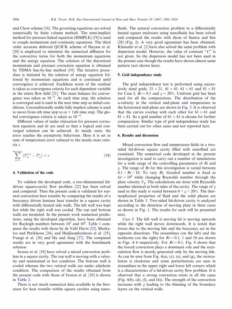
There is not much numerical data available in the liter-ature for heat transfer within square cavities using nano-
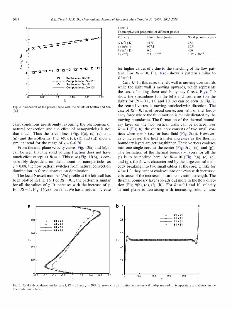
fluids. The natural convection problem in a differentiallyheated square enclosure using nanofluids has been solvedand compared the results with those of Santra and Sen[28] (Fig. 2). A very good agreement has been obtained.Khanafer et al. [2] have also solved the same problem withdispersion model. However, the value of constant ‘‘C” isnot given. So the dispersion model has not been used inthe present case though the results have shown almost samepattern (not shown here).
5. Grid independence study
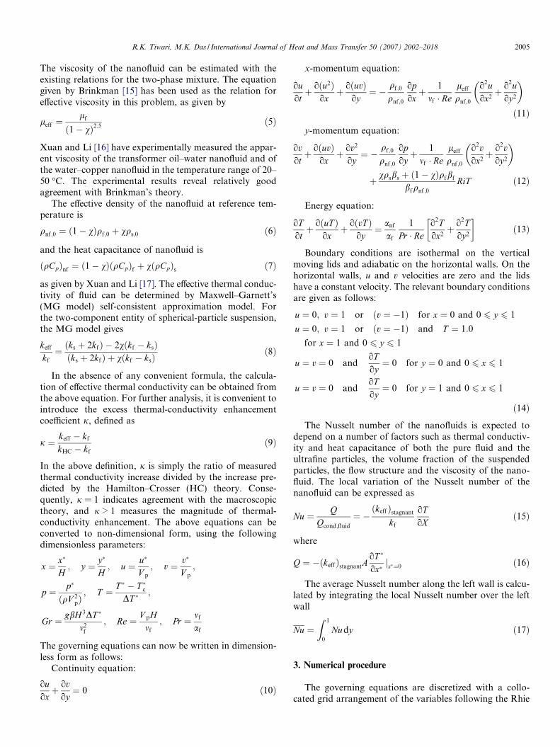
The grid independence test is performed using succes-sively sized grids, 21 � 21, 41 � 41, 61 � 61 and 81 � 81for Case I, Ri = 0.1 and v = 20%. Uniform grid has beenused for all the computations. The distribution of theu-velocity in the vertical mid-plane and temperature inthe horizontal mid-plane are shown in Fig. 3. It is observedthat the curves overlap with each other for 61 � 61 and81 � 81. So a grid number of 61 � 61 is chosen for furthercomputation. Similar type of grid independence study hasbeen carried out for other cases and not reported here.
6. Results and discussion
Mixed convection flow and temperature fields in a two-sided lid-driven square cavity filled with nanofluid areexamined. The numerical code developed in the presentinvestigation is used to carry out a number of simulationsfor a wide range of the controlling parameters of Ri andv. The range of Ri for this investigation is varied between0.1 < Ri < 10. To vary Ri, Grashof number is fixed atGr = 104 while changing Reynolds number through theplate velocity Vp. The calculations are done with Reynoldsnumber identical at both sides of the cavity. The range of vused in this study is varied between 0 < v < 20%. The ther-mophysical properties of fluid and the solid phases areshown in Table 3. Two-sided lid-driven cavity is analyzedaccording to the direction of moving plate in three casesas shown in Fig. 1. The results for each will be presentednext.
Case I: The left wall is moving lid is moving upwardswhile the right wall moves downwards. It is noted thatforces due to the moving lids and the buoyancy act in theopposite directions. The streamlines (on the left) and theisotherms (on the right) for Ri = 0.1, 1 and 10 are shownin Figs. 4–6 respectively. For Ri = 0.1, Fig. 4 shows thatthe forced convection plays a dominant role and the recir-culation flow is mostly generated only by the moving lids.As can be seen from Fig. 4(a), (c), (e), and (g), the recircu-lation is clockwise and some perturbations are seen instreamlines in the upper right and lower left corners whichis a characteristics of a lid-driven cavity flow problem. It isobserved that a strong convection exists in all the cases(Fig. 4(b), (d), (f), and (h)). The strength of the convectionincreases with v leading to the thinning of the boundarylayers on the vertical walls.
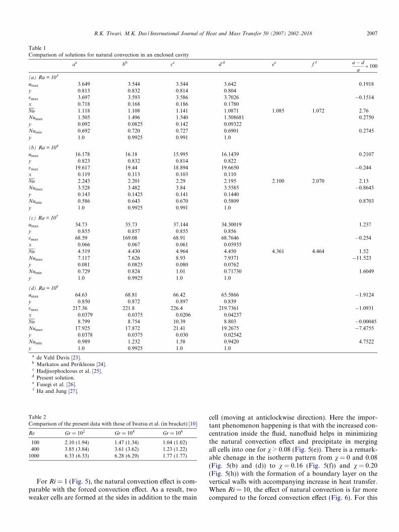
Table 1Comparison of solutions for natural convection in an enclosed cavity
aa bb cc d d ee f f a� da� 100
(a) Ra = 103
umax 3.649 3.544 3.544 3.642 0.1918y 0.813 0.832 0.814 0.804vmax 3.697 3.593 3.586 3.7026 �0.1514x 0.718 0.168 0.186 0.1780Nu 1.118 1.108 1.141 1.0871 1.085 1.072 2.76Numax 1.505 1.496 1.540 1.508681 0.2750y 0.092 0.0825 0.142 0.09322Numin 0.692 0.720 0.727 0.6901 0.2745y 1.0 0.9925 0.991 1.0
(b) Ra = 104
umax 16.178 16.18 15.995 16.1439 0.2107y 0.823 0.832 0.814 0.822vmax 19.617 19.44 18.894 19.6650 �0.244x 0.119 0.113 0.103 0.110Nu 2.243 2.201 2.29 2.195 2.100 2.070 2.13Numax 3.528 3.482 3.84 3.5585 �0.8645y 0.143 0.1425 0.141 0.1440Numin 0.586 0.643 0.670 0.5809 0.8703y 1.0 0.9925 0.991 1.0
(c) Ra = 105
umax 34.73 35.73 37.144 34.30019 1.237y 0.855 0.857 0.855 0.856vmax 68.59 169.08 68.91 68.7646 �0.254x 0.066 0.067 0.061 0.05935Nu 4.519 4.430 4.964 4.450 4.361 4.464 1.52Numax 7.117 7.626 8.93 7.9371 �11.523y 0.081 0.0825 0.080 0.0762Numin 0.729 0.824 1.01 0.71730 1.6049y 1.0 0.9925 1.0 1.0
(d) Ra = 106
umax 64.63 68.81 66.42 65.5866 �1.9124y 0.850 0.872 0.897 0.839vmax 217.36 221.8 226.4 219.7361 �1.0931x 0.0379 0.0375 0.0206 0.04237Nu 8.799 8.754 10.39 8.803 �0.00045Numax 17.925 17.872 21.41 19.2675 �7.4755y 0.0378 0.0375 0.030 0.02542Numin 0.989 1.232 1.58 0.9420 4.7522y 1.0 0.9925 1.0 1.0
a de Vahl Davis [23].b Markatos and Perikleous [24].c Hadjisophocleous et al. [25].d Present solution.e Fusegi et al. [26].f Ha and Jung [27].
Table 2Comparison of the present data with those of Iwatsu et al. (in bracket) [10]
Re Gr = 102 Gr = 104 Gr = 106
100 2.10 (1.94) 1.47 (1.34) 1.04 (1.02)400 3.85 (3.84) 3.61 (3.62) 1.23 (1.22)
1000 6.33 (6.33) 6.28 (6.29) 1.77 (1.77)
R.K. Tiwari, M.K. Das / International Journal of Heat and Mass Transfer 50 (2007) 2002–2018 2007
For Ri = 1 (Fig. 5), the natural convection effect is com-parable with the forced convection effect. As a result, twoweaker cells are formed at the sides in addition to the main
cell (moving at anticlockwise direction). Here the impor-tant phenomenon happening is that with the increased con-centration inside the fluid, nanofluid helps in minimizingthe natural convection effect and precipitate in mergingall cells into one for v > 0.08 (Fig. 5(e)). There is a remark-able chenage in the isotherm pattern from v = 0 and 0.08(Fig. 5(b) and (d)) to v = 0.16 (Fig. 5(f)) and v = 0.20(Fig. 5(h)) with the formation of a boundary layer on thevertical walls with accompanying increase in heat transfer.When Ri = 10, the effect of natural convection is far morecompared to the forced convection effect (Fig. 6). For this
χ
Ave
rage
Nu
0 0.05 0.1 0.15 0.2 0.250
2
4
6
8
10
12
Santra et al. Gr=104
Computational. Gr=104
Santra et al. Gr=105
Computational. Gr=105
Fig. 2. Validation of the present code with the results of Santra and Sen[28].
Table 3Thermophysical properties of different phases
Property Fluid phase (water) Solid phase (copper)
cp (J/kg K) 4179 383q (kg/m3) 997.1 8954k (W/m K) 0.6 400b (K�1) 2.1 � 10�4 1.67 � 10�5
2008 R.K. Tiwari, M.K. Das / International Journal of Heat and Mass Transfer 50 (2007) 2002–2018
case, conditions are strongly favouring the phenomena ofnatural convection and the effect of nanoparticles is notthat much. Thus the streamlines (Fig. 6(a), (c), (e), and(g)) and the isotherms (Fig. 6(b), (d), (f), and (h)) show asimilar trend for the range of v = 0–0.20.
From the mid-plane velocity curves Fig. 13(a) and (c), itcan be seen that the solid volume fraction does not havemuch effect except at Ri = 1. This case (Fig. 13(b)) is con-siderably dependent on the amount of nanoparticles asv > 0.08, the flow pattern switches from natural convectiondomination to forced convection domination.
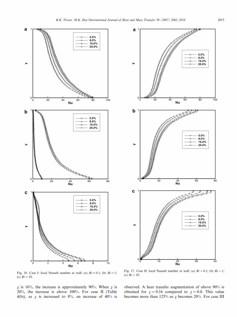
The local Nusselt number (Nu) profile at the left wall hasbeen plotted in Fig. 16. For Ri = 0.1, the pattern is similarfor all the values of v. It increases with the increase of v.For Ri = 1, Fig. 16(c) shows that Nu has a sudden increase
u
y
-0.8 -0.6 -0.4 -0.2 0 0.2 0.4 0.6 0.80
0.2
0.4
0.6
0.8
1
21 x 2141 x 4161 x 6181 x 81
Fig. 3. Grid independence test for case I, Ri = 0.1 and v = 20%: (a) u-velocity dhorizontal mid-plane.
for higher values of v due to the switching of the flow pat-tern. For Ri = 10, Fig. 16(c) shows a pattern similar toRi = 0.1.
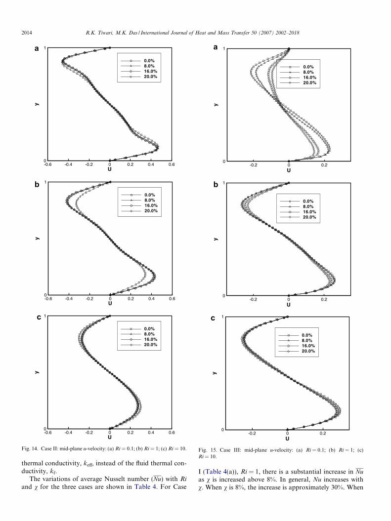
Case II: In this case, the left wall is moving downwardswhile the right wall is moving upwards, which representsthe case of aiding shear and buoyancy forces. Figs. 7–9show the streamlines (on the left) and isotherms (on theright) for Ri = 0.1, 1.0 and 10. As can be seen in Fig. 7,the central vortex is moving anticlockwise direction. Thecase of Ri = 0.1 is of forced convection with smaller buoy-ancy force where the fluid motion is mainly dictated by themoving boundaries. The formation of the thermal bound-ary layer on the two vertical walls can be noticed. ForRi = 1 (Fig. 8), the central core consists of two small vor-tices when v = 0, i.e., for base fluid (Fig. 8(a)). However,as v increases, the heat transfer increases as the thermalboundary layers are getting thinner. These vortices coalesceinto one single core at the center (Fig. 8(c), (e), and (g)).The formation of the thermal boundary layers for all thev’s is to be noticed here. At Ri = 10 (Fig. 9(a), (c), (e),and (g)), the flow is characterized by the large central maineddy breaking into two small eddies at the core. Unlike forRi = 1.0, they cannot coalesce into one even with increasedv because of the increased natural convection strength. Thethermal boundary layer spreads out more in the flow direc-tion (Fig. 9(b), (d), (f), (h)). For Ri = 0.1 and 10, velocityat mid plane is decreasing with increasing solid volume
x
T
0 0.2 0.4 0.6 0.8 10
0.2
0.4
0.6
0.8
1
21 x 2141 x 4161 x 6181 x 81
istribution in the vertical mid-plane and (b) temperature distribution in the
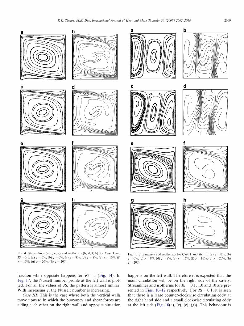
Fig. 5. Streamlines and isotherms for Case I and Ri = 1: (a) v = 0%; (b)v = 0%; (c) v = 8%; (d) v = 8%; (e) v = 16%; (f) v = 16%; (g) v = 20%; (h)v = 20%.
Fig. 4. Streamlines (a, c, e, g) and isotherms (b, d, f, h) for Case I andRi = 0.1: (a) v = 0%; (b) v = 0%; (c) v = 8%; (d) v = 8%; (e) v = 16%; (f)v = 16%; (g) v = 20%; (h) v = 20%.
R.K. Tiwari, M.K. Das / International Journal of Heat and Mass Transfer 50 (2007) 2002–2018 2009
fraction while opposite happens for Ri = 1 (Fig. 14). InFig. 17, the Nusselt number profile at the left wall is plot-ted. For all the values of Ri, the pattern is almost similar.With increasing v, the Nusselt number is increasing.
Case III: This is the case where both the vertical wallsmove upward in which the buoyancy and shear forces areaiding each other on the right wall and opposite situation
happens on the left wall. Therefore it is expected that themain circulation will be on the right side of the cavity.Streamlines and isotherms for Ri = 0.1, 1.0 and 10 are pre-sented in Figs. 10–12 respectively. For Ri = 0.1, it is seenthat there is a large counter-clockwise circulating eddy atthe right hand side and a small clockwise circulating eddyat the left side (Fig. 10(a), (c), (e), (g)). This behaviour is
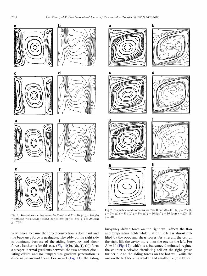
Fig. 6. Streamlines and isotherms for Case I and Ri = 10: (a) v = 0%; (b)v = 0%; (c) v = 8%; (d) v = 8%; (e) v = 16%; (f) v = 16%; (g) v = 20%; (h)v = 20%.
Fig. 7. Streamlines and isotherms for Case II and Ri = 0.1: (a) v = 0%; (b)v = 0%; (c) v = 8%; (d) v = 8%; (e) v = 16%; (f) v = 16%; (g) v = 20%; (h)v = 20%.
2010 R.K. Tiwari, M.K. Das / International Journal of Heat and Mass Transfer 50 (2007) 2002–2018
very logical because the forced convection is dominant andthe buoyancy force is negligible. The eddy on the right sideis dominant because of the aiding buoyancy and shearforces. Isotherms for this case (Fig. 10(b), (d), (f), (h)) forma steeper thermal gradients between the two counter-circu-lating eddies and no temperature gradient penetration isdiscernable around them. For Ri = 1 (Fig. 11), the aiding
buoyancy driven force on the right wall affects the flowand temperature fields while that on the left is almost nul-lified by the opposing shear forces. As a result, the cell onthe right fills the cavity more than the one on the left. ForRi = 10 (Fig. 12), which is a buoyancy dominated regime,the counter clockwise circulating cell on the right growsfurther due to the aiding forces on the hot wall while theone on the left becomes weaker and smaller, i.e., the left cell
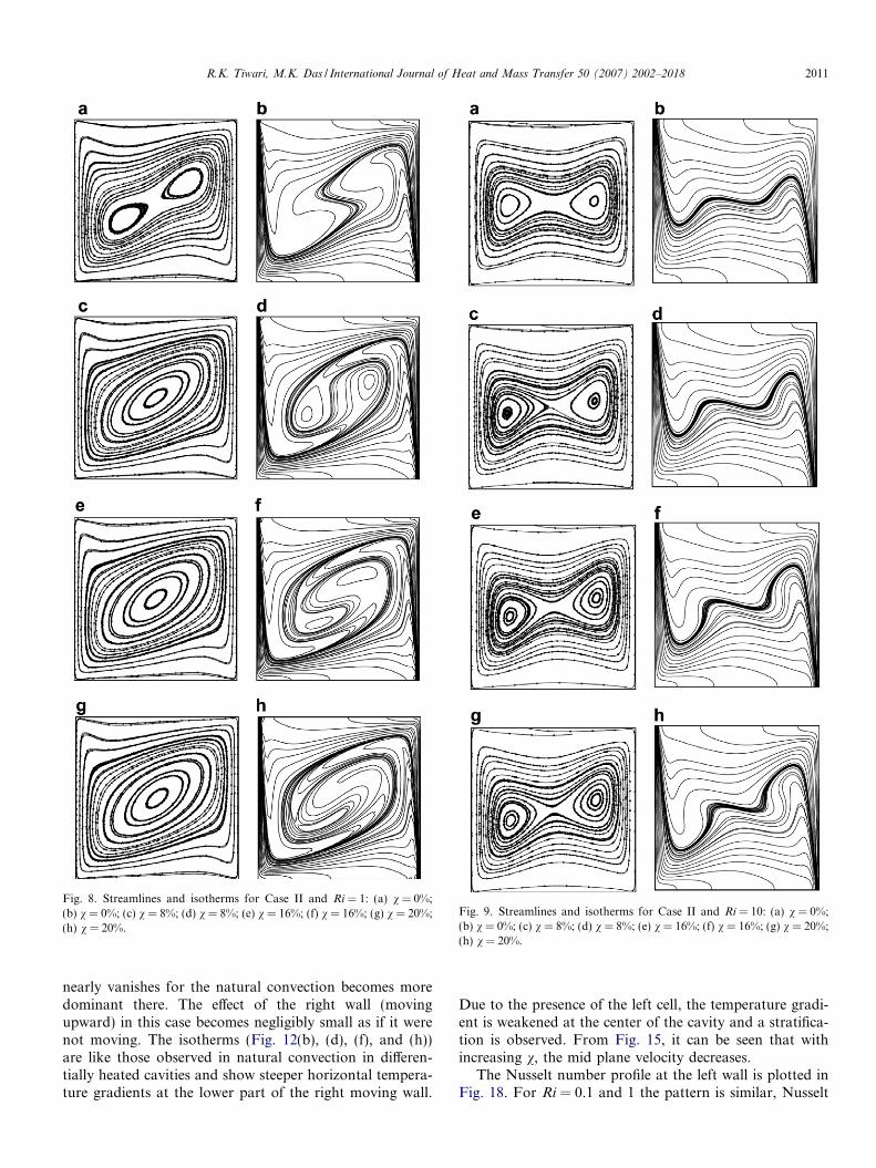
Fig. 8. Streamlines and isotherms for Case II and Ri = 1: (a) v = 0%;(b) v = 0%; (c) v = 8%; (d) v = 8%; (e) v = 16%; (f) v = 16%; (g) v = 20%;(h) v = 20%.
Fig. 9. Streamlines and isotherms for Case II and Ri = 10: (a) v = 0%;(b) v = 0%; (c) v = 8%; (d) v = 8%; (e) v = 16%; (f) v = 16%; (g) v = 20%;(h) v = 20%.
R.K. Tiwari, M.K. Das / International Journal of Heat and Mass Transfer 50 (2007) 2002–2018 2011
nearly vanishes for the natural convection becomes moredominant there. The effect of the right wall (movingupward) in this case becomes negligibly small as if it werenot moving. The isotherms (Fig. 12(b), (d), (f), and (h))are like those observed in natural convection in differen-tially heated cavities and show steeper horizontal tempera-ture gradients at the lower part of the right moving wall.
Due to the presence of the left cell, the temperature gradi-ent is weakened at the center of the cavity and a stratifica-tion is observed. From Fig. 15, it can be seen that withincreasing v, the mid plane velocity decreases.
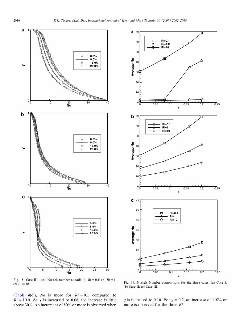
The Nusselt number profile at the left wall is plotted inFig. 18. For Ri = 0.1 and 1 the pattern is similar, Nusselt
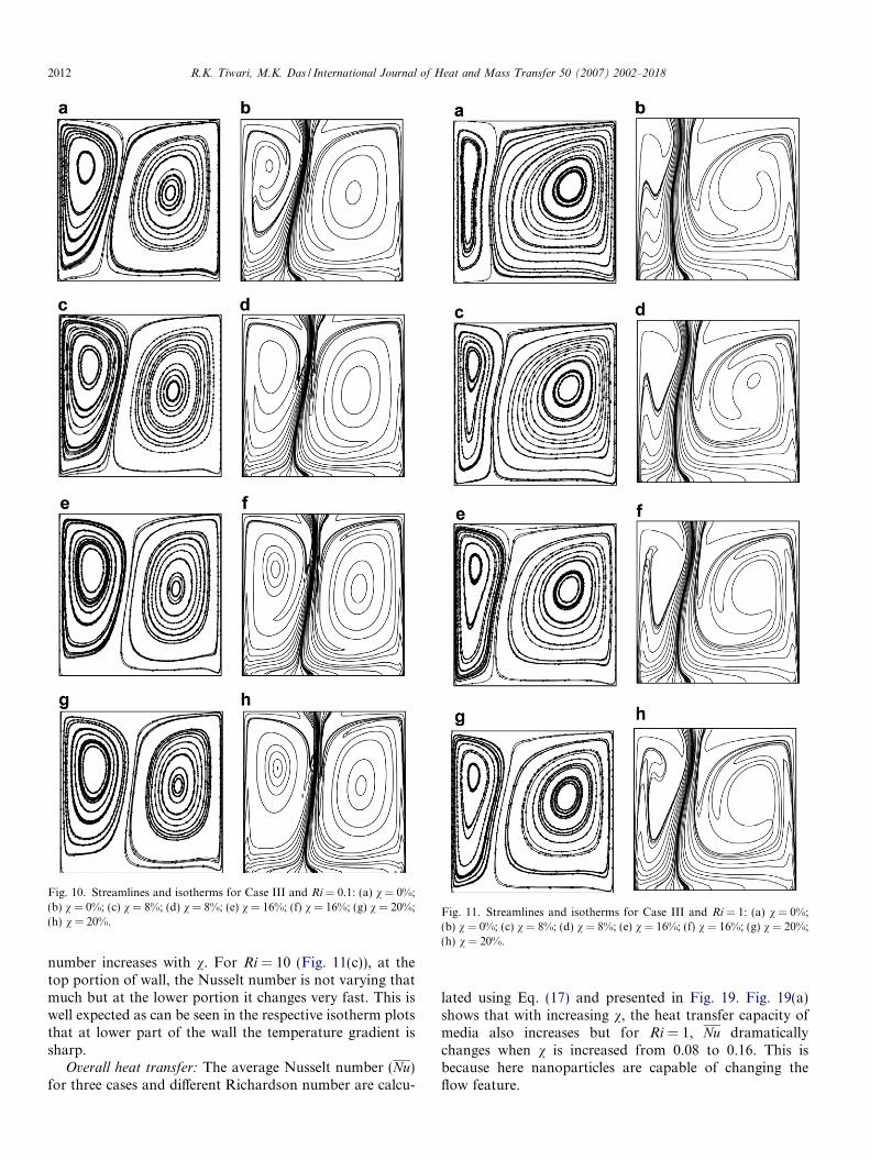
Fig. 11. Streamlines and isotherms for Case III and Ri = 1: (a) v = 0%;(b) v = 0%; (c) v = 8%; (d) v = 8%; (e) v = 16%; (f) v = 16%; (g) v = 20%;(h) v = 20%.
Fig. 10. Streamlines and isotherms for Case III and Ri = 0.1: (a) v = 0%;(b) v = 0%; (c) v = 8%; (d) v = 8%; (e) v = 16%; (f) v = 16%; (g) v = 20%;(h) v = 20%.
2012 R.K. Tiwari, M.K. Das / International Journal of Heat and Mass Transfer 50 (2007) 2002–2018
number increases with v. For Ri = 10 (Fig. 11(c)), at thetop portion of wall, the Nusselt number is not varying thatmuch but at the lower portion it changes very fast. This iswell expected as can be seen in the respective isotherm plotsthat at lower part of the wall the temperature gradient issharp.
Overall heat transfer: The average Nusselt number (Nu)for three cases and different Richardson number are calcu-
lated using Eq. (17) and presented in Fig. 19. Fig. 19(a)shows that with increasing v, the heat transfer capacity ofmedia also increases but for Ri = 1, Nu dramaticallychanges when v is increased from 0.08 to 0.16. This isbecause here nanoparticles are capable of changing theflow feature.
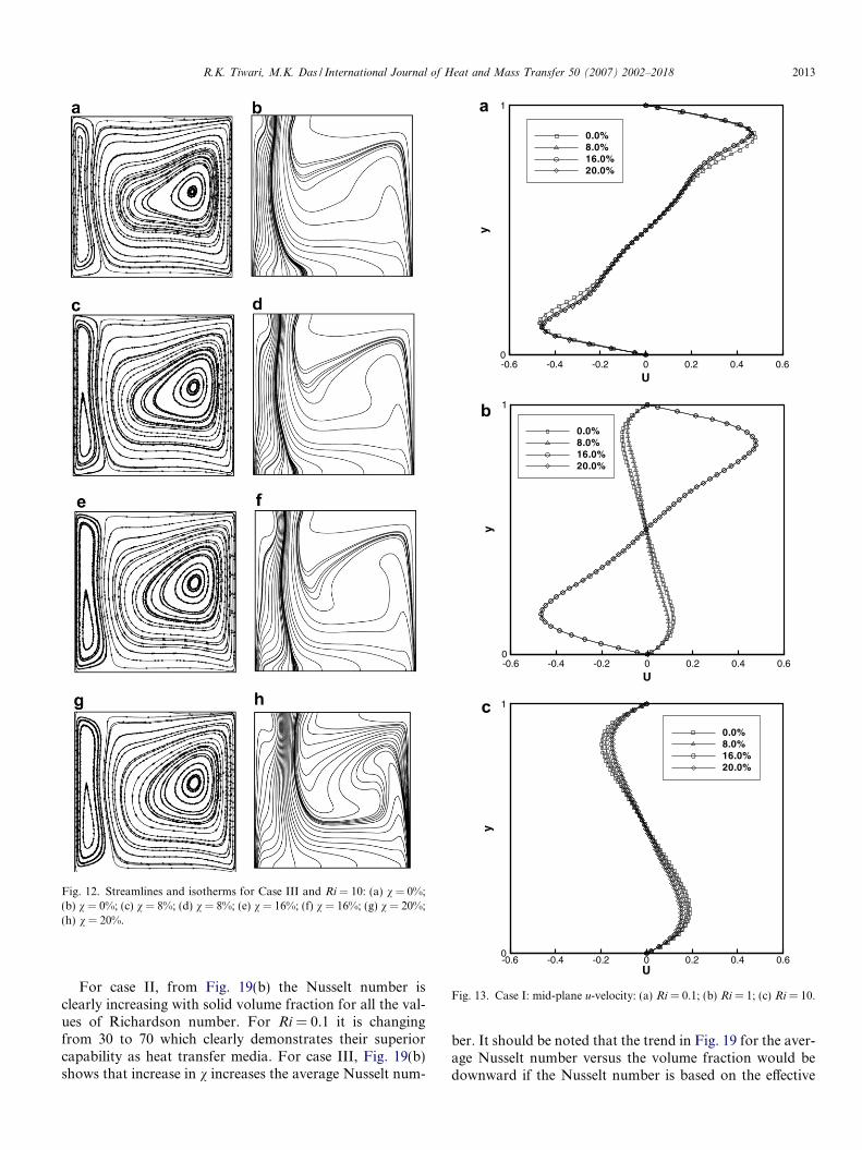
Fig. 12. Streamlines and isotherms for Case III and Ri = 10: (a) v = 0%;(b) v = 0%; (c) v = 8%; (d) v = 8%; (e) v = 16%; (f) v = 16%; (g) v = 20%;(h) v = 20%.
U
y
-0.6 -0.4 -0.2 0 0.2 0.4 0.60
1
0.0%8.0%16.0%20.0%
U
y
-0.6 -0.4 -0.2 0 0.2 0.4 0.60
1
0.0%8.0%16.0%20.0%
U
y
-0.6 -0.4 -0.2 0 0.2 0.4 0.60
1
0.0%8.0%16.0%20.0%
c
Fig. 13. Case I: mid-plane u-velocity: (a) Ri = 0.1; (b) Ri = 1; (c) Ri = 10.
R.K. Tiwari, M.K. Das / International Journal of Heat and Mass Transfer 50 (2007) 2002–2018 2013
For case II, from Fig. 19(b) the Nusselt number isclearly increasing with solid volume fraction for all the val-ues of Richardson number. For Ri = 0.1 it is changingfrom 30 to 70 which clearly demonstrates their superiorcapability as heat transfer media. For case III, Fig. 19(b)shows that increase in v increases the average Nusselt num-
ber. It should be noted that the trend in Fig. 19 for the aver-age Nusselt number versus the volume fraction would bedownward if the Nusselt number is based on the effective
U
y
-0.6 -0.4 -0.2 0 0.2 0.4 0.60
1
0.0%8.0%16.0%20.0%
U
y
-0.6 -0.4 -0.2 0 0.2 0.4 0.60
1
0.0%8.0%16.0%20.0%
U
y
-0.6 -0.4 -0.2 0 0.2 0.4 0.60
1
0.0%8.0%16.0%20.0%
Fig. 14. Case II: mid-plane u-velocity: (a) Ri = 0.1; (b) Ri = 1; (c) Ri = 10.
U
y
-0.2 0 0.20
1
0.0%8.0%16.0%20.0%
U
y
-0.2 0 0.20
1
0.0%8.0%16.0%20.0%
U
y
-0.2 0 0.20
1
0.0%8.0%16.0%20.0%
Fig. 15. Case III: mid-plane u-velocity: (a) Ri = 0.1; (b) Ri = 1; (c)Ri = 10.
2014 R.K. Tiwari, M.K. Das / International Journal of Heat and Mass Transfer 50 (2007) 2002–2018
thermal conductivity, keff, instead of the fluid thermal con-ductivity, kf.
The variations of average Nusselt number (Nu) with Ri
and v for the three cases are shown in Table 4. For Case
I (Table 4(a)), Ri = 1, there is a substantial increase in Nuas v is increased above 8%. In general, Nu increases withv. When v is 8%, the increase is approximately 30%. When
Nu
y
0 20 40 60 80 1000
1
0.0%8.0%16.0%20.0%
Nu
y
0 20 40 60 800
1
0.0%8.0%16.0%20.0%
Nu
y
0 2 4 6 8 100
1
0.0%8.0%16.0%20.0%
c
Fig. 16. Case I: local Nusselt number at wall: (a) Ri = 0.1; (b) Ri = 1;(c) Ri = 10.
Nu
y
0 20 40 60 80 1000
1
0.0%8.0%16.0%20.0%
Nu
y
0 20 40 60 800
1
0.0%8.0%16.0%20.0%
Nu
y
0 10 20 30 400
1
0.0%8.0%16.0%20.0%
Fig. 17. Case II: local Nusselt number at wall: (a) Ri = 0.1; (b) Ri = 1;(c) Ri = 10.
R.K. Tiwari, M.K. Das / International Journal of Heat and Mass Transfer 50 (2007) 2002–2018 2015
v is 16%, the increase is approximately 90%. When v is20%, the increase is above 100%. For case II (Table4(b)), as v is increased to 8%, an increase of 40% is
observed. A heat transfer augmentation of above 90% isobtained for v = 0.16 compared to v = 0.0. This valuebecomes more than 125% as v becomes 20%. For case III
χ
Ave
rage
Nu
0 0.05 0.1 0.15 0.2 0.250
10
20
30
40
50
60
70
Ri=0.1Ri=1.0Ri=10
χ
Ave
rage
Nu
0 0.05 0.1 0.15 0.2 0.250
10
20
30
40
50
60
70
Ri=0.1Ri=1Ri=10
χ
Ave
rage
Nu
0 0.05 0.1 0.15 0.2 0.250
10
20
30
40
50
60
70
Ri=0.1Ri=1Ri=10
a
Fig. 19. Nusselt Number comparisons for the three cases: (a) Case I;(b) Case II; (c) Case III.
Nu
y
0 10 20 30 400
1
0.0%8.0%16.0%20.0%
Nu
y
0 10 20 30 400
1
0.0%8.0%16.0%20.0%
Nu
y
0 5 10 15 20 25 300
1
0.0%8.0%16.0%20.0%
Fig. 18. Case III: local Nusselt number at wall: (a) Ri = 0.1; (b) Ri = 1;(c) Ri = 10.
2016 R.K. Tiwari, M.K. Das / International Journal of Heat and Mass Transfer 50 (2007) 2002–2018
(Table 4(c)), Nu is more for Ri = 0.1 compared toRi = 10.0. As v is increased to 0.08, the increase is littleabove 30%. An increment of 80% or more is observed when
v is increased to 0.16. For v = 0.2, an increase of 110% ormore is observed for the three Ri.
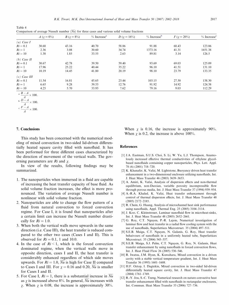
Table 4Comparison of average Nusselt number ðNuÞ for three cases and various solid volume fractions
A (v = 0%) B (v = 8%) % Increasea D (v = 16%) % Increaseb F (v = 20%) % Increasec
(a) Case I
Ri = 0.1 30.68 43.16 40.70 58.86 91.88 68.43 123.06Ri = 1 2.36 3.08 30.60 34.74 1373.16 41.31 1651.38Ri = 10 1.38 1.85 33.55 2.63 89.81 3.14 126.5
(b) Case II
Ri = 0.1 30.67 42.78 39.50 59.40 93.69 69.03 125.09Ri = 1 17.96 25.22 40.44 35.22 96.10 41.51 131.10Ri = 10 10.19 14.45 41.80 20.19 98.10 23.79 133.35
(c) Case III
Ri = 0.1 11.54 16.81 45.65 23.44 103.15 27.50 138.30Ri = 1 6.65 9.28 39.53 12.76 91.92 14.92 124.38Ri = 10 4.25 5.70 33.93 7.62 79.16 9.03 112.29
a B� AA� 100.
b D� AA� 100.
c F � AA� 100.
R.K. Tiwari, M.K. Das / International Journal of Heat and Mass Transfer 50 (2007) 2002–2018 2017
7. Conclusions
This study has been concerned with the numerical mod-eling of mixed convection in two-sided lid-driven differen-tially heated square cavity filled with nanofluid. It hasbeen performed for three different cases characterized bythe direction of movement of the vertical walls. The gov-erning parameters are Ri and v.
In view of the results, following findings may besummarized.
1. The nanoparticles when immersed in a fluid are capableof increasing the heat transfer capacity of base fluid. Assolid volume fraction increases, the effect is more pro-nounced. The variation of average Nusselt number isnonlinear with solid volume fraction.
2. Nanoparticles are able to change the flow pattern of afluid from natural convection to forced convectionregime. For Case I, it is found that nanoparticles aftera certain limit can increase the Nusselt number drasti-cally for Ri = 1.0.
3. When both the vertical walls move upwards in the samedirection (i.e. Case III), the heat transfer is reduced com-pared to the other two cases (Cases I and II). This isobserved for Ri = 0.1, 1 and 10.0.
4. In the case of Ri < 1, which is the forced convectiondominated regime, when the vertical walls move inopposite direction, cases I and II, the heat transfer isconsiderably enhanced regardless of which side movesupwards. For Ri = 1.0, Nu is high for Case II comparedto Cases I and III. For v = 0.16 and 0.20, Nu is smallerfor Cases I and II.
5. For Case I, Ri = 1, there is a substantial increase in Nuas v is increased above 8%. In general, Nu increases withv. When v is 0.08, the increase is approximately 30%.
When v is 0.16, the increase is approximately 90%.When v is 0.2, the increase is above 100%.
References
[1] J.A. Eastman, S.U.S. Choi, S. Li, W. Yu, L.J. Thompson, Anamo-lously increased effective thermal conductivities of ethylene glycol-based nanofluids containing copper nanoparticles, Phys. Lett. Appl.78 (6) (2001) 718–720.
[2] K. Khanafer, K. Vafai, M. Lightstone, Buoyancy driven heat transferenhancement in a two-dimensional enclosure utilizing nanofluids, Int.J. Heat Mass Transfer 46 (2003) 3639–3653.
[3] A. Amiri, K. Vafai, Analysis of dispersion effects and non-thermalequilibrium, non-Darcian, variable porosity incompressible flowthrough porous media, Int. J. Heat Mass Transfer 37 (1994) 939–954.
[4] A.-R.A. Khaled, K. Vafai, Heat transfer enhancement throughcontrol of thermal dispersion effects, Int. J. Heat Mass Transfer 48(2005) 2172–2185.
[5] R. Chein, G. Huang, Analysis of microchannel heat sink performanceusing nanofluids, Appl. Thermal Eng. 25 (2005) 3104–3114.
[6] J. Koo, C. Kleinstreuer, Laminar nanofluid flow in microheat-sinks,Int. J. Heat Mass Transfer 48 (2005) 2652–2661.
[7] G. Roy, C.T. Nguyen, P.-R. Lajoie, Numerical investigation oflaminar flow and heat transfer in a radial flow cooling system with theuse of nanofluids, Superlattices Microstruct. 35 (2004) 497–511.
[8] S.E.B. Maiga, C.T. Nguyen, N. Galanis, G. Roy, Heat transferbehaivours of nanofluids in a uniformly heated tube, SuperlatticesMicrostruct. 35 (2004) 543–557.
[9] S.E.B. Maiga, S.J. Palm, C.T. Nguyen, G. Roy, N. Galanis, Heattransfer enhancement by using nanofluids in forced convection flows,Int. J. Heat Fluid Flow 26 (2005) 530–546.
[10] R. Iwatsu, J.M. Hyun, K. Kuwahara, Mixed convection in a drivencavity with a stable vertical temperature gradient, Int. J. Heat MassTransfer 36 (1993) 1601–1608.
[11] H.F. Oztop, I. Dagtekin, Mixed convection in two-sided lid-drivendifferentially heated square cavity, Int. J. Heat Mass Transfer 47(2004) 1761–1769.
[12] R.-Y. Jou, S.-C. Tzeng, Numerical research on nature convective heattransfer enhancement filled with nanofluids in rectangular enclosures,Int. Commun. Heat Mass Transfer 33 (2006) 727–736.
2018 R.K. Tiwari, M.K. Das / International Journal of Heat and Mass Transfer 50 (2007) 2002–2018
[13] J.C. Maxwell, A Treatise on Electricity and Magnetism, second ed.,Oxford University Press, Cambridge, 1904, pp. 435–441.
[14] R.L. Hamilton, O.K. Crosser, Thermal conductivity of heterogeneoustwo-component systems, Ind. Eng. Chem.: Fundam. 1 (1962) 182–191.
[15] H.C. Brinkman, The viscosity of concentrated suspensions andsolutions, J. Chem. Phys. 20 (1952) 571–581.
[16] Y. Xuan, Q. Li, Report of Nanjing University of Sciences andTechnology, 1999 (in Chinese).
[17] Y. Xuan, Q. Li, Investigation on convective heat transfer and flowfeatures of nanofluids, ASME J. Heat Transfer 125 (2003) 151–155.
[18] C.M. Rhie, W.L. Chow, A numerical study of the turbulent flow pastan isolated airfoil with trailing edge separation, AIAA J. 21 (1983)1525–1532.
[19] S.V. Patankar, Numer. Heat Transfer Fluid Flow, HemispherePublication Company, NY, 1980, ISBN 0-07-048740-5.
[20] T. Hayase, J.A.C. Humphrey, R. Greif, A consistently formulatedQUICK scheme for fast and stable convergence using finite-volumeiterative calculation procedures, J. Comput. Phys. 98 (1990) 108–118.
[21] J.P. Van Doormaal, G.D. Raithby, Enhancements of the SIMPLEmethod for predicting incompressible fluid flows, Numer. HeatTransfer: Part A 7 (1984) 147–163.
[22] U. Ghia, K.N. Ghia, C.T. Shin, High Re solutions for incompressibleflow using the Navier–Stokes equations and multigrid method, J.Comput. Phys. 48 (1982) 387–411.
[23] G. de Vahl Davis, Natural convection of air in a square cavity: abenchmark solution, Int. J. Numer. Methods Fluids 3 (1983) 249–264.
[24] N.C. Markatos, K.A. Pericleous, Laminar and turbulent naturalconvection in an enclosed cavity, Int. J. Heat Mass Transfer 27 (5)(1984) 755–772.
[25] G.V. Hadjisophocleous, A.C.M. Sousa, J.E.S. Venart, Predicting thetransient natural convection in enclosures of arbitrary geometry usinga nonorthogonal numerical model, Numer. Heat Transfer: Part A 13(1998) 373–392.
[26] T. Fusegi, K. Kuwahara, B. Farouk, A numerical study of three-dimensional natural convection in a differentially heated cubicenclosure, Int. J. Heat Mass Transfer 34 (6) (1991) 1543–1557.
[27] M.Y. Ha, M.J. Jung, A numerical study of three-dimensionalconjugate heat transfer of natural convection and conduction in adifferentially heated cubic enclosure with a heat-generating cubicconducting body, Int. J. Heat Mass Transfer 43 (2000) 4229–4248.
[28] A.K. Santra, S. Sen, N. Chakraborty, Analysis of laminar naturalconvection in a square cavity using nanofluid, in: 31st NationalConference on FMFP, Jadavpur University Kolkata, December 2004,pp. 240–248.