Application of Nanofluids in Gas Turbine and Intercoolers—A ...
70
Citation: Almertejy, A.; Rashid, M.M.; Ali, N.; Almurtaji, S. Application of Nanofluids in Gas Turbine and Intercoolers—A Comprehensive Review. Nanomaterials 2022, 12, 338. https://doi.org/10.3390/ nano12030338 Academic Editor: Mikhail Sheremet Received: 29 November 2021 Accepted: 6 January 2022 Published: 21 January 2022 Publisher’s Note: MDPI stays neutral with regard to jurisdictional claims in published maps and institutional affil- iations. Copyright: © 2022 by the authors. Licensee MDPI, Basel, Switzerland. This article is an open access article distributed under the terms and conditions of the Creative Commons Attribution (CC BY) license (https:// creativecommons.org/licenses/by/ 4.0/). nanomaterials Review Application of Nanofluids in Gas Turbine and Intercoolers—A Comprehensive Review Ali Almertejy 1,2, *, Muhammad M. Rashid 1 , Naser Ali 3 and Salah Almurtaji 2,4 1 Department of Mechatronics Engineering, Faculty of Engineering, International Islamic University Malaysia, Jalan Gombak, Kuala Lumpur 53100, Malaysia; [email protected] 2 Kuwait Army, Kuwait Ministry of Defense, Safat 13128, Kuwait; [email protected] 3 Nanotechnology and Applications Program, Energy and Building Research Center, Kuwait Institute for Scientific Research, Safat 13109, Kuwait; [email protected] 4 School of Aerospace, Transport and Manufacturing (SATM), Cranfield University, Cranfield MK43 0AL, UK * Correspondence: [email protected] Abstract: Today, the optimal use of non-renewable energy sources, reducing pollution, and increasing the efficiency of power-generating cycles are of particular importance. There are several ways to increase the efficiency of gas turbines; one that has recently attracted attention is to use an intercooler. However, the efficiency of the heat exchanger used in intercoolers depends on the type of heat exchanger, the characteristics of the operating fluid and the thermal boundary layers, and the pump speed. Improving the thermophysical properties of the working fluid is a passive method of increasing heat transfer, which has attracted the attention of those researching engineering applications. The current review addresses the latest methods of improving gas turbine efficiency using nanofluids and includes experimental and numerical studies. First, the general principles governing turbines are described, then the commonly used types of heat exchangers are introduced. Finally, studies on the use of nanofluids in heat exchangers are reviewed. The technology of producing nanoparticles that can be used in heat exchangers is also discussed. This review article can provide the reader with comprehensive information on making nanofluids and using them in heat exchangers used as intercoolers. Keywords: gas turbine; intercooler; heat transfer; heat exchanger; thermal efficiency; nanofluid 1. Introduction Although power generation from nuclear power plants has been on the rise recently, in most countries electricity is generated from thermal or hybrid power plants with gas turbines the main components. The last 20 years represent a period of rapid advance for gas turbine technology driven by increased demand for this type of installation. Enhancing the efficiency of gas turbines can increase the efficiency of the power plant, reducing both air pollution and the consumption of non-renewable energy sources. There are several ways to increase the efficiency of a gas turbine. One is to increase the efficiency of the gas turbines by using an intercooler to reduce the gas temperature in the low-pressure compressor (LP), reducing the compressor power consumption and increasing the power generated by the turbine. Different heat exchangers are used in the intercoolers used in gas turbines. Schematics of the gas turbine cycle without and with an intercooler are shown in Figures 1 and 2, respectively. The heat exchanger directly affects intercooler performance and gas turbine cycle efficiency. The type of heat exchanger and operational fluid flow regime have most effect on the efficiency of the heat exchanger [1]. Nanomaterials 2022, 12, 338. https://doi.org/10.3390/nano12030338 https://www.mdpi.com/journal/nanomaterials
-
Upload
khangminh22 -
Category
Documents
-
view
6 -
download
0
Transcript of Application of Nanofluids in Gas Turbine and Intercoolers—A ...
�����������������
Citation: Almertejy, A.; Rashid, M.M.;
Ali, N.; Almurtaji, S. Application of
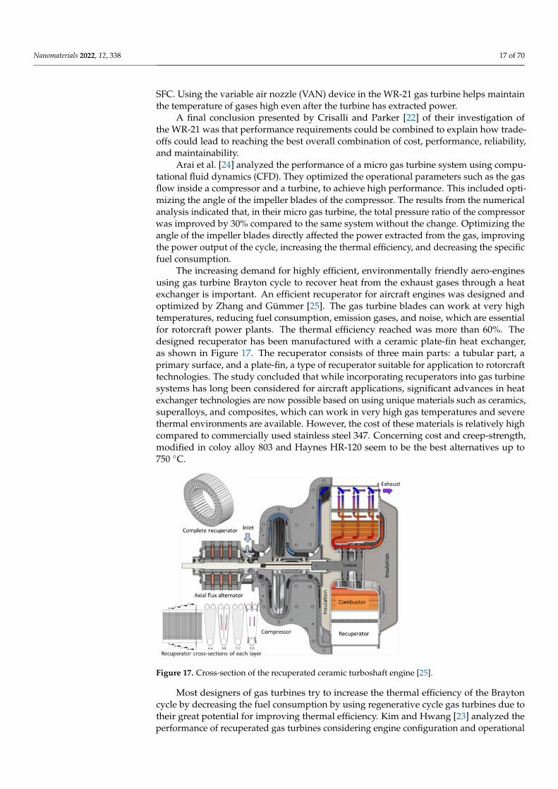
Nanofluids in Gas Turbine and
Intercoolers—A Comprehensive
Review. Nanomaterials 2022, 12, 338.
https://doi.org/10.3390/
nano12030338
Academic Editor: Mikhail Sheremet
Received: 29 November 2021
Accepted: 6 January 2022
Published: 21 January 2022
Publisher’s Note: MDPI stays neutral
with regard to jurisdictional claims in
published maps and institutional affil-
iations.
Copyright: © 2022 by the authors.
Licensee MDPI, Basel, Switzerland.
This article is an open access article
distributed under the terms and
conditions of the Creative Commons
Attribution (CC BY) license (https://
creativecommons.org/licenses/by/
4.0/).
nanomaterials
Review
Application of Nanofluids in Gas Turbine and Intercoolers—AComprehensive ReviewAli Almertejy 1,2,*, Muhammad M. Rashid 1, Naser Ali 3 and Salah Almurtaji 2,4
1 Department of Mechatronics Engineering, Faculty of Engineering, International Islamic University Malaysia,Jalan Gombak, Kuala Lumpur 53100, Malaysia; [email protected]
2 Kuwait Army, Kuwait Ministry of Defense, Safat 13128, Kuwait; [email protected] Nanotechnology and Applications Program, Energy and Building Research Center, Kuwait Institute for
Scientific Research, Safat 13109, Kuwait; [email protected] School of Aerospace, Transport and Manufacturing (SATM), Cranfield University, Cranfield MK43 0AL, UK* Correspondence: [email protected]
Abstract: Today, the optimal use of non-renewable energy sources, reducing pollution, and increasingthe efficiency of power-generating cycles are of particular importance. There are several ways toincrease the efficiency of gas turbines; one that has recently attracted attention is to use an intercooler.However, the efficiency of the heat exchanger used in intercoolers depends on the type of heatexchanger, the characteristics of the operating fluid and the thermal boundary layers, and the pumpspeed. Improving the thermophysical properties of the working fluid is a passive method of increasingheat transfer, which has attracted the attention of those researching engineering applications. Thecurrent review addresses the latest methods of improving gas turbine efficiency using nanofluidsand includes experimental and numerical studies. First, the general principles governing turbinesare described, then the commonly used types of heat exchangers are introduced. Finally, studies onthe use of nanofluids in heat exchangers are reviewed. The technology of producing nanoparticlesthat can be used in heat exchangers is also discussed. This review article can provide the readerwith comprehensive information on making nanofluids and using them in heat exchangers used asintercoolers.
Keywords: gas turbine; intercooler; heat transfer; heat exchanger; thermal efficiency; nanofluid
1. Introduction
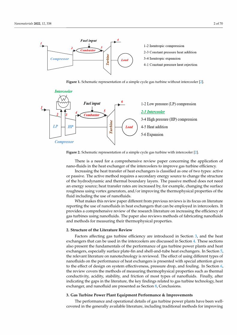
Although power generation from nuclear power plants has been on the rise recently,in most countries electricity is generated from thermal or hybrid power plants with gasturbines the main components. The last 20 years represent a period of rapid advance forgas turbine technology driven by increased demand for this type of installation. Enhancingthe efficiency of gas turbines can increase the efficiency of the power plant, reducing bothair pollution and the consumption of non-renewable energy sources. There are severalways to increase the efficiency of a gas turbine. One is to increase the efficiency of thegas turbines by using an intercooler to reduce the gas temperature in the low-pressurecompressor (LP), reducing the compressor power consumption and increasing the powergenerated by the turbine. Different heat exchangers are used in the intercoolers used in gasturbines. Schematics of the gas turbine cycle without and with an intercooler are shown inFigures 1 and 2, respectively. The heat exchanger directly affects intercooler performanceand gas turbine cycle efficiency. The type of heat exchanger and operational fluid flowregime have most effect on the efficiency of the heat exchanger [1].
Nanomaterials 2022, 12, 338. https://doi.org/10.3390/nano12030338 https://www.mdpi.com/journal/nanomaterials
Nanomaterials 2022, 12, 338 2 of 70Nanomaterials 2022, 12, x FOR PEER REVIEW 2 of 70
Figure 1. Schematic representation of a simple cycle gas turbine without intercooler [2].
Figure 2. Schematic representation of a simple cycle gas turbine with intercooler [2].
Increasing the heat transfer of heat exchangers is classified as one of two types: active or passive. The active method requires a secondary energy source to change the structure of the hydrodynamic and thermal boundary layers. The passive method does not need an energy source; heat transfer rates are increased by, for example, changing the surface roughness using vortex generators, and/or improving the thermophysical properties of the fluid including the use of nanofluids.
What makes this review paper different from previous reviews is its focus on litera-ture reporting the use of nanofluids in heat exchangers that can be employed in intercool-ers. It provides a comprehensive review of the research literature on increasing the effi-ciency of gas turbines using nanofluids. The paper also reviews methods of fabricating nanofluids and methods for measuring their thermophysical properties.
2. Structure of the Literature Review Factors affecting gas turbine efficiency are introduced in Section 3, and the heat ex-
changers that can be used in the intercoolers are discussed in Section 4. These sections also present the fundamentals of the performance of gas turbine power plants and heat ex-changers, especially surface plate-fin and shell-and-tube heat exchangers. In Section 5, the relevant literature on nanotechnology is reviewed. The effect of using different types of nanofluids on the performance of heat exchangers is presented with special attention given to the effect of design on system effectiveness, pressure drop, and fouling. In Section 6, the review covers the methods of measuring thermophysical properties such as thermal conductivity, acidity, stability, and friction of most types of nanofluids. Finally, after in-dicating the gaps in the literature, the key findings related to gas turbine technology, heat exchanger, and nanofluid are presented as Section 8, Conclusions.
Figure 1. Schematic representation of a simple cycle gas turbine without intercooler [2].
Nanomaterials 2022, 12, x FOR PEER REVIEW 2 of 70
Figure 1. Schematic representation of a simple cycle gas turbine without intercooler [2].
Figure 2. Schematic representation of a simple cycle gas turbine with intercooler [2].
Increasing the heat transfer of heat exchangers is classified as one of two types: active or passive. The active method requires a secondary energy source to change the structure of the hydrodynamic and thermal boundary layers. The passive method does not need an energy source; heat transfer rates are increased by, for example, changing the surface roughness using vortex generators, and/or improving the thermophysical properties of the fluid including the use of nanofluids.
What makes this review paper different from previous reviews is its focus on litera-ture reporting the use of nanofluids in heat exchangers that can be employed in intercool-ers. It provides a comprehensive review of the research literature on increasing the effi-ciency of gas turbines using nanofluids. The paper also reviews methods of fabricating nanofluids and methods for measuring their thermophysical properties.
2. Structure of the Literature Review Factors affecting gas turbine efficiency are introduced in Section 3, and the heat ex-
changers that can be used in the intercoolers are discussed in Section 4. These sections also present the fundamentals of the performance of gas turbine power plants and heat ex-changers, especially surface plate-fin and shell-and-tube heat exchangers. In Section 5, the relevant literature on nanotechnology is reviewed. The effect of using different types of nanofluids on the performance of heat exchangers is presented with special attention given to the effect of design on system effectiveness, pressure drop, and fouling. In Section 6, the review covers the methods of measuring thermophysical properties such as thermal conductivity, acidity, stability, and friction of most types of nanofluids. Finally, after in-dicating the gaps in the literature, the key findings related to gas turbine technology, heat exchanger, and nanofluid are presented as Section 8, Conclusions.
Figure 2. Schematic representation of a simple cycle gas turbine with intercooler [2].
There is a need for a comprehensive review paper concerning the application ofnano-fluids in the heat exchanger of the intercoolers to improve gas turbine efficiency.
Increasing the heat transfer of heat exchangers is classified as one of two types: activeor passive. The active method requires a secondary energy source to change the structureof the hydrodynamic and thermal boundary layers. The passive method does not needan energy source; heat transfer rates are increased by, for example, changing the surfaceroughness using vortex generators, and/or improving the thermophysical properties of thefluid including the use of nanofluids.
What makes this review paper different from previous reviews is its focus on literaturereporting the use of nanofluids in heat exchangers that can be employed in intercoolers. Itprovides a comprehensive review of the research literature on increasing the efficiency ofgas turbines using nanofluids. The paper also reviews methods of fabricating nanofluidsand methods for measuring their thermophysical properties.
2. Structure of the Literature Review
Factors affecting gas turbine efficiency are introduced in Section 3, and the heatexchangers that can be used in the intercoolers are discussed in Section 4. These sectionsalso present the fundamentals of the performance of gas turbine power plants and heatexchangers, especially surface plate-fin and shell-and-tube heat exchangers. In Section 5,the relevant literature on nanotechnology is reviewed. The effect of using different types ofnanofluids on the performance of heat exchangers is presented with special attention givento the effect of design on system effectiveness, pressure drop, and fouling. In Section 6,the review covers the methods of measuring thermophysical properties such as thermalconductivity, acidity, stability, and friction of most types of nanofluids. Finally, afterindicating the gaps in the literature, the key findings related to gas turbine technology, heatexchanger, and nanofluid are presented as Section 8, Conclusions.
3. Gas Turbine Power Plant Equipment Performance & Improvements
The performance and operational details of gas turbine power plants have been well-covered in the generally available literature, including traditional methods for improving

Nanomaterials 2022, 12, 338 3 of 70
the performance and effectiveness of heat exchangers such as the use of intercoolers andrecuperators. Generally, academic research and industrial development in turbomachineryhave been extensive and include gas turbine energy generation in industries such asaviation, power generation, and oil and gas. Despite decades of incremental improvements,the thermal efficiencies of simple cycles remain low, and the means to improve thesegenerally involve the provision of heat exchangers, reheat, and intercooler compression.
Three factors differentiate the industrial gas turbine from the aircraft gas turbine.First, the operational life requirements of an industrial gas turbine are in the order of50,000 h before the first shop visit or a major overhaul, almost ten times the duration of anaircraft gas turbine. Second, the importance of weight and size limitations on the aircraftpropulsion system are not usually critical for industrial power plants. Third, the aircraft gasturbine can use the exhaust gas kinetic energy, whereas it might be wasted and minimizedwith other types. Figure 3 shows the typical Siemens SGT-100 industrial gas turbine. Thisunit has been used in such different applications for generating electricity and as a turbogas engine in aircraft.
Nanomaterials 2022, 12, x FOR PEER REVIEW 3 of 70
3. Gas Turbine Power Plant Equipment Performance & Improvements The performance and operational details of gas turbine power plants have been well-
covered in the generally available literature, including traditional methods for improving the performance and effectiveness of heat exchangers such as the use of intercoolers and recuperators. Generally, academic research and industrial development in turbomachin-ery have been extensive and include gas turbine energy generation in industries such as aviation, power generation, and oil and gas. Despite decades of incremental improve-ments, the thermal efficiencies of simple cycles remain low, and the means to improve these generally involve the provision of heat exchangers, reheat, and intercooler compres-sion.
Three factors differentiate the industrial gas turbine from the aircraft gas turbine. First, the operational life requirements of an industrial gas turbine are in the order of 50,000 h before the first shop visit or a major overhaul, almost ten times the duration of an aircraft gas turbine. Second, the importance of weight and size limitations on the aircraft propulsion system are not usually critical for industrial power plants. Third, the aircraft gas turbine can use the exhaust gas kinetic energy, whereas it might be wasted and mini-mized with other types. Figure 3 shows the typical Siemens SGT-100 industrial gas tur-bine. This unit has been used in such different applications for generating electricity and as a turbo gas engine in aircraft.
In general, gas turbines technology has three main application fields, which are: First: open cycle gas turbines, which produce only power, Second: cogeneration systems in which both heat and power are produced, Third: a combination of both of the above. The different applications can significantly affect the design, and therefore it is essen-
tial to identify the requirements during the design phase.
Figure 3. Siemens SGT-100 gas turbine.
However, in the last decade, there has been significant investment in introducing aero-derivative gas turbines to industrial applications. These are popular for energy gen-eration due to their reliability, flexibility, and higher efficiency. Advanced aerospace en-gine technologies have produced gas turbines with lighter weight, smaller size, faster re-sponse, and lower emissions than their heavy industrial counterparts. With up to 45% efficiency compared to 35% for heavier gas turbines, they are often good for smaller-scale (up to 100 MW) energy generation plants. The aero turbines are also popular due to their fuel flexibility as they operate on a range of natural gas and liquid fuel combinations [3].
A number of researchers have performed numerical studies on the factors affecting the performance of gas turbines, which will be reviewed and discussed here. Cetin [4] analyzed and optimized gas turbine performance numerically and analytically. He
Figure 3. Siemens SGT-100 gas turbine.
In general, gas turbines technology has three main application fields, which are:First: open cycle gas turbines, which produce only power,Second: cogeneration systems in which both heat and power are produced,Third: a combination of both of the above.The different applications can significantly affect the design, and therefore it is essential
to identify the requirements during the design phase.However, in the last decade, there has been significant investment in introducing
aero-derivative gas turbines to industrial applications. These are popular for energygeneration due to their reliability, flexibility, and higher efficiency. Advanced aerospaceengine technologies have produced gas turbines with lighter weight, smaller size, fasterresponse, and lower emissions than their heavy industrial counterparts. With up to 45%efficiency compared to 35% for heavier gas turbines, they are often good for smaller-scale(up to 100 MW) energy generation plants. The aero turbines are also popular due to theirfuel flexibility as they operate on a range of natural gas and liquid fuel combinations [3].
A number of researchers have performed numerical studies on the factors affecting theperformance of gas turbines, which will be reviewed and discussed here. Cetin [4] analyzedand optimized gas turbine performance numerically and analytically. He simulated turbineperformance factors such as power output, work ratio, thermal efficiency, fuel consumption,rate of gas emission as a function of such operational parameters as compressor inlettemperature, turbine inlet temperature, maximum pressure and temperature, and heatexchanger effectiveness. The results showed that decreasing the air inlet temperatureincreased the net power of the simple cycle. Also, increasing the inlet turbine temperatureimproved the plant’s thermal efficiency.

Nanomaterials 2022, 12, 338 4 of 70
The vital factor affecting the performance of the gas turbine is thermal efficiency.Although the thermal efficiency of open cycle gas turbine systems is very low, they are stillthe preferred option to supply peak electricity loads because these plants can be broughtup to an operational capacity quickly, and their costs are considerably lower than those ofother systems [5].
Shi and Che [6] designed and tested a combined cycle power plant operated by naturalgas and installed with waste heat recovery. Parametric analyses were performed for theproposed combined cycle to evaluate the effects of several factors, including gas turbineinlet temperature, condenser pressure, fuel gas heating temperature, and the proposedcycle’s performance. When the condenser pressure was decreased for a given turbineinlet temperature, the net electrical efficiency of the proposed cycle increased. Heatingthe fuel resulted in higher gas turbine efficiency due to the reduced fuel flow. The effectof compressor design parameters such as inlet temperature, pressure ratio, gas specificheat on the gas turbine performance were investigated numerically by Xie et al. [7]. Theydeveloped a theoretical model for a closed, simple Brayton gas turbine cycle. The factorsaffecting the power output and thermal efficiency were investigated. The results showedthat decreasing compressor work by reducing the specific volume of inlet air increased thenet power of the cycle and increased thermal efficiency.
Kurt et al. [8] numerically investigated the factors affecting the performance of anopen cycle gas turbine. Thermodynamic and exergy analyses of the cycle were carriedout numerically to identify the best operation and optimization factors. Also, the effect ofinlet air temperature into the compressor on the performance of the ideal gas turbine wasstudied, as was the effect of flow gases into the first stage of the gas turbine. The pressureratio, thermal efficiency, and power output of the cycle were taken as the main performanceparameters. The Brayton gas turbine cycle was analyzed and modeled numerically. Mostfactors affecting the performance of the cycle were checked directly. Table 1 shows theoptimum pressure ratio value according to turbine inlet temperature for maximum netpower output at ma = 1 kg/s, with compressor inlet temperature 288.15 K, turbine efficiencyηc = 0.85, and η = 0.88. Table 2 also shows the effect of compressor inlet temperature on gasturbine performance. According to the results obtained from the thermodynamic analysisof the open cycle gas turbine system, the compressor inlet temperature (CIT), turbineinlet temperature (TIT), and pressure ratio (PR) are the parameters that most significantlyeffect gas turbine performance such as net power output, thermal efficiency, and fuelconsumption of the cycle.
Table 1. Pressure ratio with turbine inlet temperature for compressor inlet temperature 288.15 K [8].
TIT (K)
.Wnet−PR
ηcyc(%).Wnet(kW) PR
1000 222.355 6 31.421100 280.741 8 34.631200 341.54 10 36.931300 404.124 12 38.651400 466.891 16 40.941500 528.603 18 41.751600 586.712 22 43.00
Generally, microturbines generate electrical power at a rate in the range of 5–200 kW,and mini turbines in the range of 200–500 kW. Typically, the thermal efficiency of microtur-bines is about 20% or less if no recuperator is included in the system. In this regard, Shah [9]designed and tested a compact heat exchanger of selected materials to improve the thermalefficiency of microturbines. He investigated the cost, performance, durability, and otherrelated issues of a compact heat exchanger for use with microturbines. The inclusion of arecuperator exchanger with an effectiveness of 87% raised the efficiency of the gas turbinesystem to 30% approximately. However, the total cost of the plant was increased such
Nanomaterials 2022, 12, 338 5 of 70
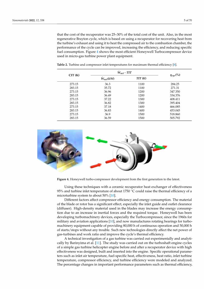
that the cost of the recuperator was 25–30% of the total cost of the unit. Also, in the mostregenerative Brayton cycle, which is based on using a recuperator for recovering heat fromthe turbine’s exhaust and using it to heat the compressed air to the combustion chamber, theperformance of the cycle can be improved, increasing the efficiency, and reducing specificfuel consumption. Figure 4 shows the most efficient Honeywell Turbocompressor deviceused in micro-gas turbine power plant equipment.
Table 2. Turbine and compressor inlet temperatures for maximum thermal efficiency [8].
CIT (K)
.Wnet−TIT
ηcyc(%).Wnet(kW) TIT (K)
273.15 36.3 1100 284.25283.15 35.72 1100 271.31273.15 36.96 1200 347.350283.15 36.49 1200 334.376273.15 37.22 1300 408.411283.15 36.82 1300 395.404273.15 37.18 1400 466.085283.15 36.83 1400 453.045273.15 36.9 1500 518.860283.15 36.59 1500 505.792
Nanomaterials 2022, 12, x FOR PEER REVIEW 5 of 70
Table 2. Turbine and compressor inlet temperatures for maximum thermal efficiency [8].
CIT (K) 𝑾𝒏𝒆𝒕 − 𝑻𝑰𝑻 𝜼𝒄𝒚𝒄(%) 𝑾𝒏𝒆𝒕(𝒌𝑾) 𝑻𝑰𝑻 (𝑲) 273.15 36.3 1100 284.25 283.15 35.72 1100 271.31 273.15 36.96 1200 347.350 283.15 36.49 1200 334.376 273.15 37.22 1300 408.411 283.15 36.82 1300 395.404 273.15 37.18 1400 466.085 283.15 36.83 1400 453.045 273.15 36.9 1500 518.860 283.15 36.59 1500 505.792
Generally, microturbines generate electrical power at a rate in the range of 5–200 kW, and mini turbines in the range of 200–500 kW. Typically, the thermal efficiency of micro-turbines is about 20% or less if no recuperator is included in the system. In this regard, Shah [9] designed and tested a compact heat exchanger of selected materials to improve the thermal efficiency of microturbines. He investigated the cost, performance, durability, and other related issues of a compact heat exchanger for use with microturbines. The in-clusion of a recuperator exchanger with an effectiveness of 87% raised the efficiency of the gas turbine system to 30% approximately. However, the total cost of the plant was in-creased such that the cost of the recuperator was 25–30% of the total cost of the unit. Also, in the most regenerative Brayton cycle, which is based on using a recuperator for recov-ering heat from the turbine’s exhaust and using it to heat the compressed air to the com-bustion chamber, the performance of the cycle can be improved, increasing the efficiency, and reducing specific fuel consumption. Figure 4 shows the most efficient Honeywell Tur-bocompressor device used in micro-gas turbine power plant equipment.
Using these techniques with a ceramic recuperator heat exchanger of effectiveness 95% and turbine inlet temperature of about 1750 °C could raise the thermal efficiency of a microturbine system to about 50% [10].
Figure 4. Honeywell turbo-compressor development from the first generation to the latest.
Different factors affect compressor efficiency and energy consumption. The material of the blade or rotor has a significant effect, especially the inlet guide and outlet clearance (diffuser). High-density material used in the blades may increase the energy consumption due to an increase in inertial forces and the required torque. Honeywell has been devel-oping turbomachinery devices, especially the Turbocompressor, since the 1960s for mili-tary and aviation applications [10], and now manufactures rotating bearings for tur-bomachinery equipment capable of providing 80,000 h of continuous operation and 50,000 h of starts/stops without any trouble. Such new technologies directly affect the net power of gas-turbines and work ratio and improve the cycle’s thermal efficiency.
Figure 4. Honeywell turbo-compressor development from the first generation to the latest.
Using these techniques with a ceramic recuperator heat exchanger of effectiveness95% and turbine inlet temperature of about 1750 ◦C could raise the thermal efficiency of amicroturbine system to about 50% [10].
Different factors affect compressor efficiency and energy consumption. The materialof the blade or rotor has a significant effect, especially the inlet guide and outlet clearance(diffuser). High-density material used in the blades may increase the energy consump-tion due to an increase in inertial forces and the required torque. Honeywell has beendeveloping turbomachinery devices, especially the Turbocompressor, since the 1960s formilitary and aviation applications [10], and now manufactures rotating bearings for turbo-machinery equipment capable of providing 80,000 h of continuous operation and 50,000 hof starts/stops without any trouble. Such new technologies directly affect the net power ofgas-turbines and work ratio and improve the cycle’s thermal efficiency.
A technical investigation of a gas turbine was carried out experimentally and analyti-cally by Barinyima et al. [11]. The study was carried out on the turboshaft engine cyclesof a simple gas turbine helicopter engine before and after a recuperator device with higheffectiveness was designed, built and inserted into the engine. Specific operational parame-ters such as inlet air temperature, fuel-specific heat, effectiveness, heat ratio, inlet turbinetemperature, compressor efficiency, and turbine efficiency were modeled and analyzed.The percentage changes in important performance parameters such as thermal efficiency,
Nanomaterials 2022, 12, 338 6 of 70
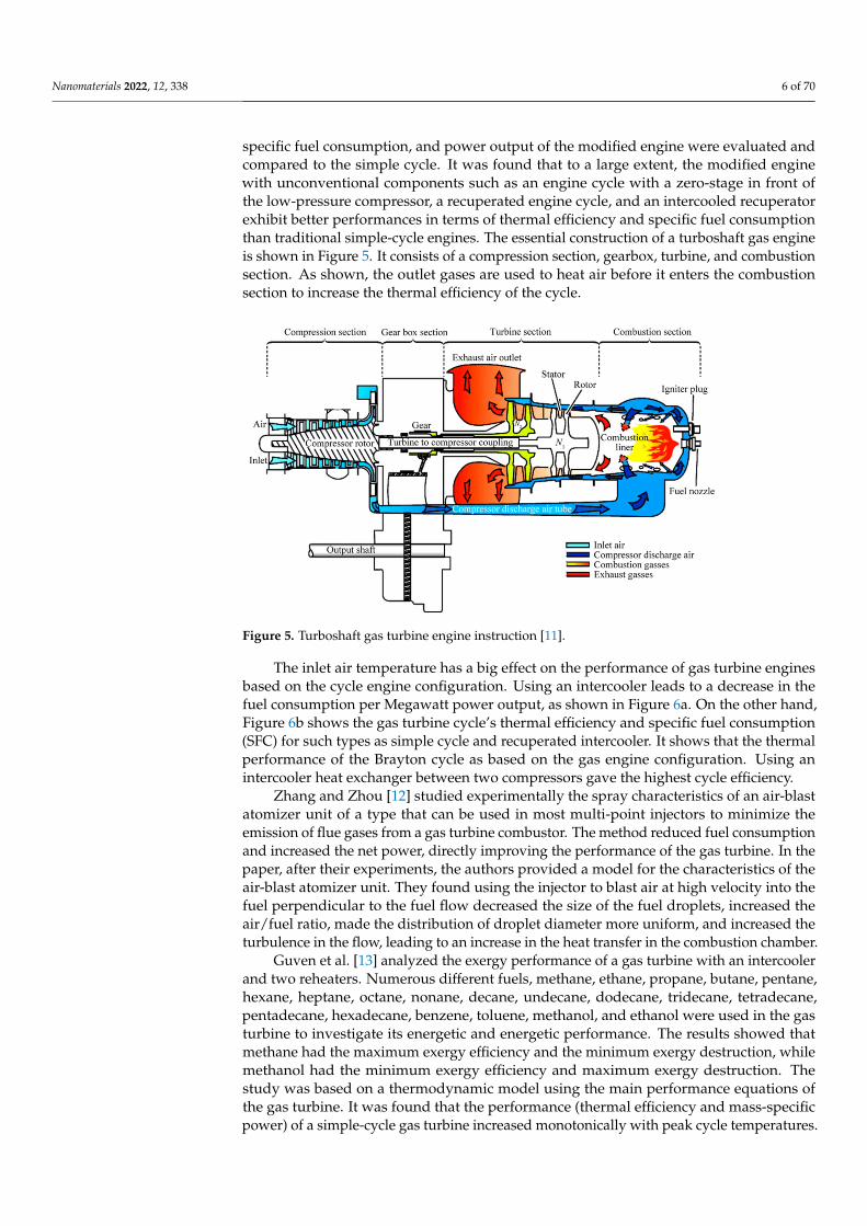
specific fuel consumption, and power output of the modified engine were evaluated andcompared to the simple cycle. It was found that to a large extent, the modified enginewith unconventional components such as an engine cycle with a zero-stage in front ofthe low-pressure compressor, a recuperated engine cycle, and an intercooled recuperatorexhibit better performances in terms of thermal efficiency and specific fuel consumptionthan traditional simple-cycle engines. The essential construction of a turboshaft gas engineis shown in Figure 5. It consists of a compression section, gearbox, turbine, and combustionsection. As shown, the outlet gases are used to heat air before it enters the combustionsection to increase the thermal efficiency of the cycle.
Nanomaterials 2022, 12, x FOR PEER REVIEW 6 of 70
A technical investigation of a gas turbine was carried out experimentally and analyt-ically by Barinyima et al. [11]. The study was carried out on the turboshaft engine cycles of a simple gas turbine helicopter engine before and after a recuperator device with high effectiveness was designed, built and inserted into the engine. Specific operational param-eters such as inlet air temperature, fuel-specific heat, effectiveness, heat ratio, inlet turbine temperature, compressor efficiency, and turbine efficiency were modeled and analyzed. The percentage changes in important performance parameters such as thermal efficiency, specific fuel consumption, and power output of the modified engine were evaluated and compared to the simple cycle. It was found that to a large extent, the modified engine with unconventional components such as an engine cycle with a zero-stage in front of the low-pressure compressor, a recuperated engine cycle, and an intercooled recuperator exhibit better performances in terms of thermal efficiency and specific fuel consumption than tra-ditional simple-cycle engines. The essential construction of a turboshaft gas engine is shown in Figure 5. It consists of a compression section, gearbox, turbine, and combustion section. As shown, the outlet gases are used to heat air before it enters the combustion section to increase the thermal efficiency of the cycle.
Figure 5. Turboshaft gas turbine engine instruction [11].
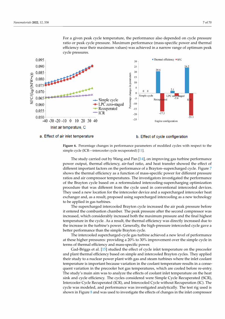
The inlet air temperature has a big effect on the performance of gas turbine engines based on the cycle engine configuration. Using an intercooler leads to a decrease in the fuel consumption per Megawatt power output, as shown in Figure 6a. On the other hand, Figure 6b shows the gas turbine cycle’s thermal efficiency and specific fuel consumption (SFC) for such types as simple cycle and recuperated intercooler. It shows that the thermal performance of the Brayton cycle as based on the gas engine configuration. Using an in-tercooler heat exchanger between two compressors gave the highest cycle efficiency.
Zhang and Zhou [12] studied experimentally the spray characteristics of an air-blast atomizer unit of a type that can be used in most multi-point injectors to minimize the emission of flue gases from a gas turbine combustor. The method reduced fuel consump-tion and increased the net power, directly improving the performance of the gas turbine. In the paper, after their experiments, the authors provided a model for the characteristics of the air-blast atomizer unit. They found using the injector to blast air at high velocity into the fuel perpendicular to the fuel flow decreased the size of the fuel droplets, in-creased the air/fuel ratio, made the distribution of droplet diameter more uniform, and increased the turbulence in the flow, leading to an increase in the heat transfer in the com-bustion chamber.
Figure 5. Turboshaft gas turbine engine instruction [11].
The inlet air temperature has a big effect on the performance of gas turbine enginesbased on the cycle engine configuration. Using an intercooler leads to a decrease in thefuel consumption per Megawatt power output, as shown in Figure 6a. On the other hand,Figure 6b shows the gas turbine cycle’s thermal efficiency and specific fuel consumption(SFC) for such types as simple cycle and recuperated intercooler. It shows that the thermalperformance of the Brayton cycle as based on the gas engine configuration. Using anintercooler heat exchanger between two compressors gave the highest cycle efficiency.
Zhang and Zhou [12] studied experimentally the spray characteristics of an air-blastatomizer unit of a type that can be used in most multi-point injectors to minimize theemission of flue gases from a gas turbine combustor. The method reduced fuel consumptionand increased the net power, directly improving the performance of the gas turbine. In thepaper, after their experiments, the authors provided a model for the characteristics of theair-blast atomizer unit. They found using the injector to blast air at high velocity into thefuel perpendicular to the fuel flow decreased the size of the fuel droplets, increased theair/fuel ratio, made the distribution of droplet diameter more uniform, and increased theturbulence in the flow, leading to an increase in the heat transfer in the combustion chamber.
Guven et al. [13] analyzed the exergy performance of a gas turbine with an intercoolerand two reheaters. Numerous different fuels, methane, ethane, propane, butane, pentane,hexane, heptane, octane, nonane, decane, undecane, dodecane, tridecane, tetradecane,pentadecane, hexadecane, benzene, toluene, methanol, and ethanol were used in the gasturbine to investigate its energetic and energetic performance. The results showed thatmethane had the maximum exergy efficiency and the minimum exergy destruction, whilemethanol had the minimum exergy efficiency and maximum exergy destruction. Thestudy was based on a thermodynamic model using the main performance equations ofthe gas turbine. It was found that the performance (thermal efficiency and mass-specificpower) of a simple-cycle gas turbine increased monotonically with peak cycle temperatures.
Nanomaterials 2022, 12, 338 7 of 70
For a given peak cycle temperature, the performance also depended on cycle pressureratio or peak cycle pressure. Maximum performance (mass-specific power and thermalefficiency near their maximum values) was achieved in a narrow range of optimum peakcycle pressures.
Nanomaterials 2022, 12, x FOR PEER REVIEW 7 of 70
Figure 6. Percentage changes in performance parameters of modified cycles with respect to the sim-ple cycle (ICR—intercooler cycle recuperated) [11].
Guven et al. [13] analyzed the exergy performance of a gas turbine with an inter-cooler and two reheaters. Numerous different fuels, methane, ethane, propane, butane, pentane, hexane, heptane, octane, nonane, decane, undecane, dodecane, tridecane, tetra-decane, pentadecane, hexadecane, benzene, toluene, methanol, and ethanol were used in the gas turbine to investigate its energetic and energetic performance. The results showed that methane had the maximum exergy efficiency and the minimum exergy destruction, while methanol had the minimum exergy efficiency and maximum exergy destruction. The study was based on a thermodynamic model using the main performance equations of the gas turbine. It was found that the performance (thermal efficiency and mass-specific power) of a simple-cycle gas turbine increased monotonically with peak cycle tempera-tures. For a given peak cycle temperature, the performance also depended on cycle pres-sure ratio or peak cycle pressure. Maximum performance (mass-specific power and ther-mal efficiency near their maximum values) was achieved in a narrow range of optimum peak cycle pressures.
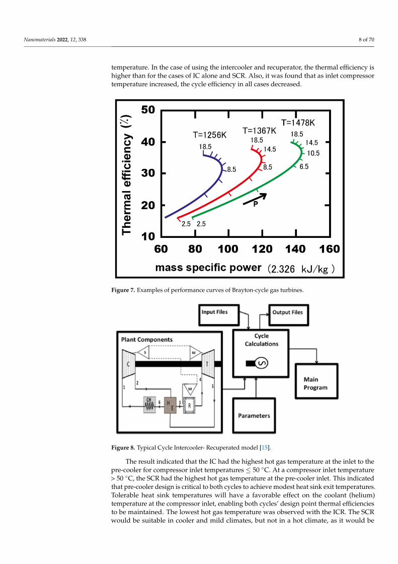
The study carried out by Wang and Pan [14], on improving gas turbine performance power output, thermal efficiency, air-fuel ratio, and heat transfer showed the effect of dif-ferent important factors on the performance of a Brayton–supercharged cycle. Figure 7 shows the thermal efficiency as a function of mass-specific power for different pressure ratios and air compressor temperatures. The investigators investigated the performance of the Brayton cycle based on a reformulated intercooling-supercharging optimization procedure that was different from the cycle used in conventional intercooled devices. They used a new location for the intercooler device and a supercharged intercooler heat exchanger and, as a result, proposed using supercharged intercooling as a new technology to be applied in gas turbines.
The supercharged intercooled Brayton cycle increased the air peak pressure before it entered the combustion chamber. The peak pressure after the second compressor was in-creased, which considerably increased both the maximum pressure and the final highest temperature in the cycle. As a result, the thermal efficiency was directly increased due to the increase in the turbine’s power. Generally, the high-pressure intercooled cycle gave a better performance than the simple Brayton cycle.
Figure 6. Percentage changes in performance parameters of modified cycles with respect to thesimple cycle (ICR—intercooler cycle recuperated) [11].
The study carried out by Wang and Pan [14], on improving gas turbine performancepower output, thermal efficiency, air-fuel ratio, and heat transfer showed the effect ofdifferent important factors on the performance of a Brayton–supercharged cycle. Figure 7shows the thermal efficiency as a function of mass-specific power for different pressureratios and air compressor temperatures. The investigators investigated the performanceof the Brayton cycle based on a reformulated intercooling-supercharging optimizationprocedure that was different from the cycle used in conventional intercooled devices.They used a new location for the intercooler device and a supercharged intercooler heatexchanger and, as a result, proposed using supercharged intercooling as a new technologyto be applied in gas turbines.
The supercharged intercooled Brayton cycle increased the air peak pressure beforeit entered the combustion chamber. The peak pressure after the second compressor wasincreased, which considerably increased both the maximum pressure and the final highesttemperature in the cycle. As a result, the thermal efficiency was directly increased due tothe increase in the turbine’s power. Generally, the high-pressure intercooled cycle gave abetter performance than the simple Brayton cycle.
The intercooled supercharged-cycle gas turbine achieved a new level of performanceat these higher pressures: providing a 20% to 30% improvement over the simple cycle interms of thermal efficiency and mass-specific power.
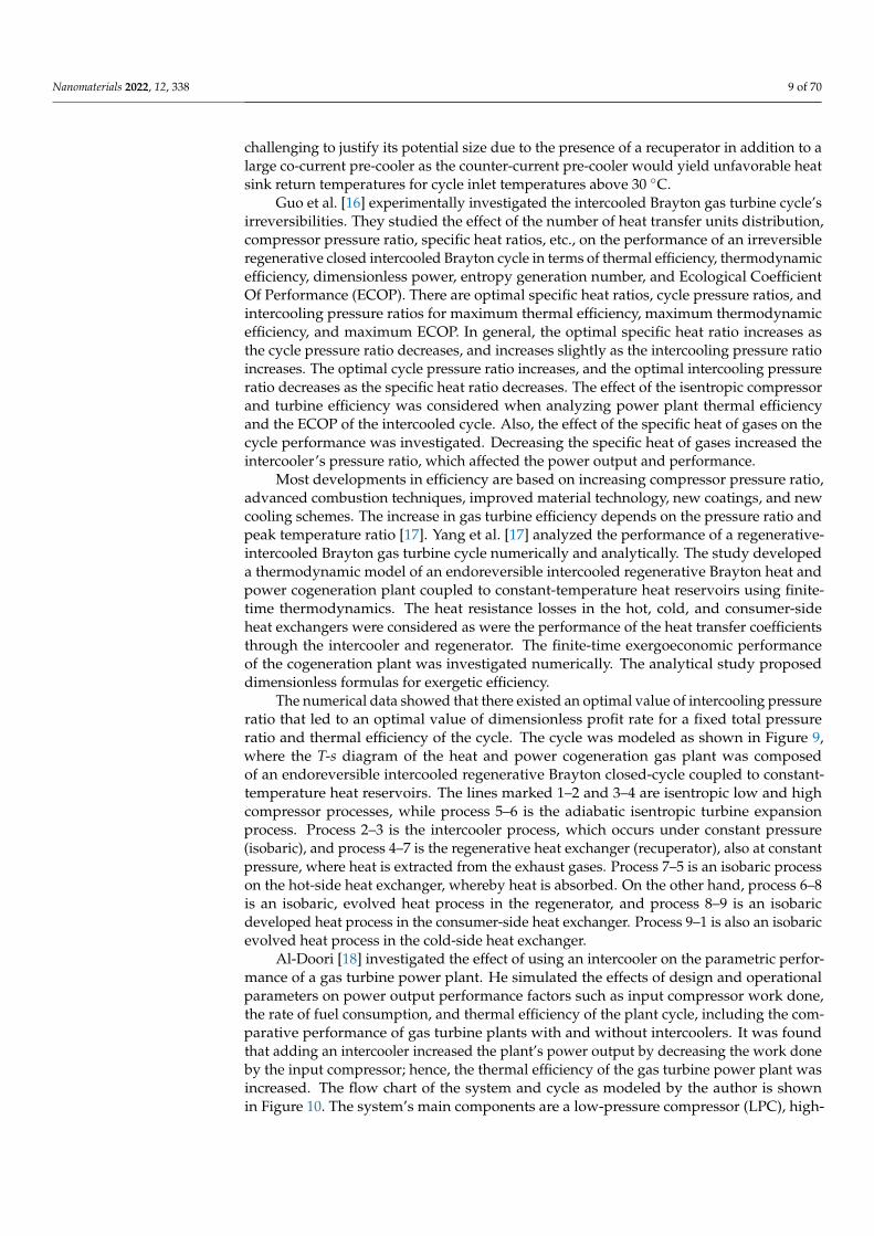
Gad-Briggs et al. [15] studied the effect of cycle inlet temperature on the precoolerand plant thermal efficiency based on simple and intercooled Brayton cycles. They appliedtheir study to a nuclear power plant with gas and steam turbines where the inlet coolanttemperature is important because variation in the coolant temperature results in a conse-quent variation in the precooler hot gas temperatures, which are cooled before re-entry.The study’s main aim was to analyze the effects of coolant inlet temperature on the heatsink and cycle efficiency. The cycles considered were Simple Cycle Recuperated (SCR),Intercooler Cycle Recuperated (ICR), and Intercooled Cycle without Recuperation (IC). Thecycle was modeled, and performance was investigated analytically. The test rig used isshown in Figure 8 and was used to investigate the effects of changes in the inlet compressor
Nanomaterials 2022, 12, 338 8 of 70
temperature. In the case of using the intercooler and recuperator, the thermal efficiency ishigher than for the cases of IC alone and SCR. Also, it was found that as inlet compressortemperature increased, the cycle efficiency in all cases decreased.
Nanomaterials 2022, 12, x FOR PEER REVIEW 8 of 70
Figure 7. Examples of performance curves of Brayton-cycle gas turbines.
The intercooled supercharged-cycle gas turbine achieved a new level of performance at these higher pressures: providing a 20% to 30% improvement over the simple cycle in terms of thermal efficiency and mass-specific power.
Gad-Briggs et al. [15] studied the effect of cycle inlet temperature on the precooler and plant thermal efficiency based on simple and intercooled Brayton cycles. They applied their study to a nuclear power plant with gas and steam turbines where the inlet coolant temperature is important because variation in the coolant temperature results in a conse-quent variation in the precooler hot gas temperatures, which are cooled before re-entry. The study’s main aim was to analyze the effects of coolant inlet temperature on the heat sink and cycle efficiency. The cycles considered were Simple Cycle Recuperated (SCR), Intercooler Cycle Recuperated (ICR), and Intercooled Cycle without Recuperation (IC). The cycle was modeled, and performance was investigated analytically. The test rig used is shown in Figure 8 and was used to investigate the effects of changes in the inlet com-pressor temperature. In the case of using the intercooler and recuperator, the thermal ef-ficiency is higher than for the cases of IC alone and SCR. Also, it was found that as inlet compressor temperature increased, the cycle efficiency in all cases decreased.
The result indicated that the IC had the highest hot gas temperature at the inlet to the pre-cooler for compressor inlet temperatures ≤ 50 °C. At a compressor inlet temperature > 50 °C, the SCR had the highest hot gas temperature at the pre-cooler inlet. This indicated that pre-cooler design is critical to both cycles to achieve modest heat sink exit tempera-tures. Tolerable heat sink temperatures will have a favorable effect on the coolant (helium) temperature at the compressor inlet, enabling both cycles’ design point thermal efficien-cies to be maintained. The lowest hot gas temperature was observed with the ICR. The SCR would be suitable in cooler and mild climates, but not in a hot climate, as it would be challenging to justify its potential size due to the presence of a recuperator in addition to a large co-current pre-cooler as the counter-current pre-cooler would yield unfavorable heat sink return temperatures for cycle inlet temperatures above 30 °C.
Figure 7. Examples of performance curves of Brayton-cycle gas turbines.
Nanomaterials 2022, 12, x FOR PEER REVIEW 9 of 70
Figure 8. Typical Cycle Intercooler- Recuperated model [15].
Guo et al. [16] experimentally investigated the intercooled Brayton gas turbine cy-cle’s irreversibilities. They studied the effect of the number of heat transfer units distribu-tion, compressor pressure ratio, specific heat ratios, etc., on the performance of an irre-versible regenerative closed intercooled Brayton cycle in terms of thermal efficiency, ther-modynamic efficiency, dimensionless power, entropy generation number, and Ecological Coefficient Of Performance (ECOP). There are optimal specific heat ratios, cycle pressure ratios, and intercooling pressure ratios for maximum thermal efficiency, maximum ther-modynamic efficiency, and maximum ECOP. In general, the optimal specific heat ratio increases as the cycle pressure ratio decreases, and increases slightly as the intercooling pressure ratio increases. The optimal cycle pressure ratio increases, and the optimal inter-cooling pressure ratio decreases as the specific heat ratio decreases. The effect of the isen-tropic compressor and turbine efficiency was considered when analyzing power plant thermal efficiency and the ECOP of the intercooled cycle. Also, the effect of the specific heat of gases on the cycle performance was investigated. Decreasing the specific heat of gases increased the intercooler’s pressure ratio, which affected the power output and per-formance.
Most developments in efficiency are based on increasing compressor pressure ratio, advanced combustion techniques, improved material technology, new coatings, and new cooling schemes. The increase in gas turbine efficiency depends on the pressure ratio and peak temperature ratio [17]. Yang et al. [17] analyzed the performance of a regenerative-intercooled Brayton gas turbine cycle numerically and analytically. The study developed a thermodynamic model of an endoreversible intercooled regenerative Brayton heat and power cogeneration plant coupled to constant-temperature heat reservoirs using finite-time thermodynamics. The heat resistance losses in the hot, cold, and consumer-side heat exchangers were considered as were the performance of the heat transfer coefficients through the intercooler and regenerator. The finite-time exergoeconomic performance of the cogeneration plant was investigated numerically. The analytical study proposed di-mensionless formulas for exergetic efficiency.
The numerical data showed that there existed an optimal value of intercooling pres-sure ratio that led to an optimal value of dimensionless profit rate for a fixed total pressure ratio and thermal efficiency of the cycle. The cycle was modeled as shown in Figure 9, where the T-s diagram of the heat and power cogeneration gas plant was composed of an endoreversible intercooled regenerative Brayton closed-cycle coupled to constant-temper-ature heat reservoirs. The lines marked 1–2 and 3–4 are isentropic low and high compres-sor processes, while process 5–6 is the adiabatic isentropic turbine expansion process.
Figure 8. Typical Cycle Intercooler- Recuperated model [15].
The result indicated that the IC had the highest hot gas temperature at the inlet to thepre-cooler for compressor inlet temperatures ≤ 50 ◦C. At a compressor inlet temperature> 50 ◦C, the SCR had the highest hot gas temperature at the pre-cooler inlet. This indicatedthat pre-cooler design is critical to both cycles to achieve modest heat sink exit temperatures.Tolerable heat sink temperatures will have a favorable effect on the coolant (helium)temperature at the compressor inlet, enabling both cycles’ design point thermal efficienciesto be maintained. The lowest hot gas temperature was observed with the ICR. The SCRwould be suitable in cooler and mild climates, but not in a hot climate, as it would be
Nanomaterials 2022, 12, 338 9 of 70
challenging to justify its potential size due to the presence of a recuperator in addition to alarge co-current pre-cooler as the counter-current pre-cooler would yield unfavorable heatsink return temperatures for cycle inlet temperatures above 30 ◦C.
Guo et al. [16] experimentally investigated the intercooled Brayton gas turbine cycle’sirreversibilities. They studied the effect of the number of heat transfer units distribution,compressor pressure ratio, specific heat ratios, etc., on the performance of an irreversibleregenerative closed intercooled Brayton cycle in terms of thermal efficiency, thermodynamicefficiency, dimensionless power, entropy generation number, and Ecological CoefficientOf Performance (ECOP). There are optimal specific heat ratios, cycle pressure ratios, andintercooling pressure ratios for maximum thermal efficiency, maximum thermodynamicefficiency, and maximum ECOP. In general, the optimal specific heat ratio increases asthe cycle pressure ratio decreases, and increases slightly as the intercooling pressure ratioincreases. The optimal cycle pressure ratio increases, and the optimal intercooling pressureratio decreases as the specific heat ratio decreases. The effect of the isentropic compressorand turbine efficiency was considered when analyzing power plant thermal efficiencyand the ECOP of the intercooled cycle. Also, the effect of the specific heat of gases on thecycle performance was investigated. Decreasing the specific heat of gases increased theintercooler’s pressure ratio, which affected the power output and performance.
Most developments in efficiency are based on increasing compressor pressure ratio,advanced combustion techniques, improved material technology, new coatings, and newcooling schemes. The increase in gas turbine efficiency depends on the pressure ratio andpeak temperature ratio [17]. Yang et al. [17] analyzed the performance of a regenerative-intercooled Brayton gas turbine cycle numerically and analytically. The study developeda thermodynamic model of an endoreversible intercooled regenerative Brayton heat andpower cogeneration plant coupled to constant-temperature heat reservoirs using finite-time thermodynamics. The heat resistance losses in the hot, cold, and consumer-sideheat exchangers were considered as were the performance of the heat transfer coefficientsthrough the intercooler and regenerator. The finite-time exergoeconomic performanceof the cogeneration plant was investigated numerically. The analytical study proposeddimensionless formulas for exergetic efficiency.
The numerical data showed that there existed an optimal value of intercooling pressureratio that led to an optimal value of dimensionless profit rate for a fixed total pressureratio and thermal efficiency of the cycle. The cycle was modeled as shown in Figure 9,where the T-s diagram of the heat and power cogeneration gas plant was composedof an endoreversible intercooled regenerative Brayton closed-cycle coupled to constant-temperature heat reservoirs. The lines marked 1–2 and 3–4 are isentropic low and highcompressor processes, while process 5–6 is the adiabatic isentropic turbine expansionprocess. Process 2–3 is the intercooler process, which occurs under constant pressure(isobaric), and process 4–7 is the regenerative heat exchanger (recuperator), also at constantpressure, where heat is extracted from the exhaust gases. Process 7–5 is an isobaric processon the hot-side heat exchanger, whereby heat is absorbed. On the other hand, process 6–8is an isobaric, evolved heat process in the regenerator, and process 8–9 is an isobaricdeveloped heat process in the consumer-side heat exchanger. Process 9–1 is also an isobaricevolved heat process in the cold-side heat exchanger.
Al-Doori [18] investigated the effect of using an intercooler on the parametric perfor-mance of a gas turbine power plant. He simulated the effects of design and operationalparameters on power output performance factors such as input compressor work done,the rate of fuel consumption, and thermal efficiency of the plant cycle, including the com-parative performance of gas turbine plants with and without intercoolers. It was foundthat adding an intercooler increased the plant’s power output by decreasing the work doneby the input compressor; hence, the thermal efficiency of the gas turbine power plant wasincreased. The flow chart of the system and cycle as modeled by the author is shownin Figure 10. The system’s main components are a low-pressure compressor (LPC), high-

Nanomaterials 2022, 12, 338 10 of 70
pressure compressor (HPC), turbine, combustion chamber, and intercooler heat exchanger.There is no recuperator in the cycle.
Nanomaterials 2022, 12, x FOR PEER REVIEW 10 of 70
Process 2–3 is the intercooler process, which occurs under constant pressure (isobaric), and process 4–7 is the regenerative heat exchanger (recuperator), also at constant pressure, where heat is extracted from the exhaust gases. Process 7–5 is an isobaric process on the hot-side heat exchanger, whereby heat is absorbed. On the other hand, process 6–8 is an isobaric, evolved heat process in the regenerator, and process 8–9 is an isobaric developed heat process in the consumer-side heat exchanger. Process 9–1 is also an isobaric evolved heat process in the cold-side heat exchanger.
Figure 9. T-s diagram for the cycle model [17].
Al-Doori [18] investigated the effect of using an intercooler on the parametric perfor-mance of a gas turbine power plant. He simulated the effects of design and operational parameters on power output performance factors such as input compressor work done, the rate of fuel consumption, and thermal efficiency of the plant cycle, including the com-parative performance of gas turbine plants with and without intercoolers. It was found that adding an intercooler increased the plant’s power output by decreasing the work done by the input compressor; hence, the thermal efficiency of the gas turbine power plant was increased. The flow chart of the system and cycle as modeled by the author is shown in Figure 10. The system’s main components are a low-pressure compressor (LPC), high-pressure compressor (HPC), turbine, combustion chamber, and intercooler heat ex-changer. There is no recuperator in the cycle.
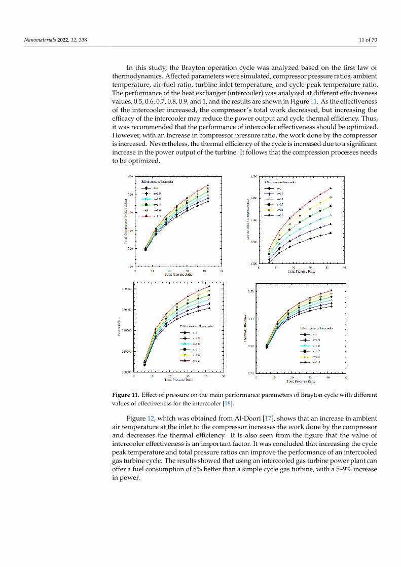
In this study, the Brayton operation cycle was analyzed based on the first law of ther-modynamics. Affected parameters were simulated, compressor pressure ratios, ambient temperature, air-fuel ratio, turbine inlet temperature, and cycle peak temperature ratio. The performance of the heat exchanger (intercooler) was analyzed at different effective-ness values, 0.5, 0.6, 0.7, 0.8, 0.9, and 1, and the results are shown in Figure 11. As the effectiveness of the intercooler increased, the compressor’s total work decreased, but in-creasing the efficacy of the intercooler may reduce the power output and cycle thermal efficiency. Thus, it was recommended that the performance of intercooler effectiveness should be optimized. However, with an increase in compressor pressure ratio, the work done by the compressor is increased. Nevertheless, the thermal efficiency of the cycle is increased due to a significant increase in the power output of the turbine. It follows that the compression processes needs to be optimized.
Figure 9. T-s diagram for the cycle model [17].Nanomaterials 2022, 12, x FOR PEER REVIEW 11 of 70
Figure 10. Schematic layout for the simulated intercooled gas turbine cycle [2].
Figure 10. Schematic layout for the simulated intercooled gas turbine cycle [2].
Nanomaterials 2022, 12, 338 11 of 70
In this study, the Brayton operation cycle was analyzed based on the first law ofthermodynamics. Affected parameters were simulated, compressor pressure ratios, ambienttemperature, air-fuel ratio, turbine inlet temperature, and cycle peak temperature ratio.The performance of the heat exchanger (intercooler) was analyzed at different effectivenessvalues, 0.5, 0.6, 0.7, 0.8, 0.9, and 1, and the results are shown in Figure 11. As the effectivenessof the intercooler increased, the compressor’s total work decreased, but increasing theefficacy of the intercooler may reduce the power output and cycle thermal efficiency. Thus,it was recommended that the performance of intercooler effectiveness should be optimized.However, with an increase in compressor pressure ratio, the work done by the compressoris increased. Nevertheless, the thermal efficiency of the cycle is increased due to a significantincrease in the power output of the turbine. It follows that the compression processes needsto be optimized.
Nanomaterials 2022, 12, x FOR PEER REVIEW 11 of 70
Figure 10. Schematic layout for the simulated intercooled gas turbine cycle [2].
Figure 11. Effect of pressure on the main performance parameters of Brayton cycle with differentvalues of effectiveness for the intercooler [18].
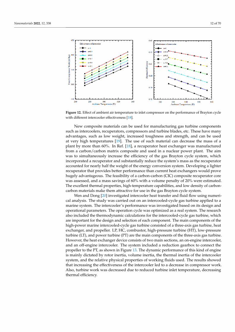
Figure 12, which was obtained from Al-Doori [17], shows that an increase in ambientair temperature at the inlet to the compressor increases the work done by the compressorand decreases the thermal efficiency. It is also seen from the figure that the value ofintercooler effectiveness is an important factor. It was concluded that increasing the cyclepeak temperature and total pressure ratios can improve the performance of an intercooledgas turbine cycle. The results showed that using an intercooled gas turbine power plant canoffer a fuel consumption of 8% better than a simple cycle gas turbine, with a 5–9% increasein power.
Nanomaterials 2022, 12, 338 12 of 70
Nanomaterials 2022, 12, x FOR PEER REVIEW 12 of 70
Figure 11. Effect of pressure on the main performance parameters of Brayton cycle with different values of effectiveness for the intercooler [18].
Figure 12, which was obtained from Al-Doori [17], shows that an increase in ambient air temperature at the inlet to the compressor increases the work done by the compressor and decreases the thermal efficiency. It is also seen from the figure that the value of inter-cooler effectiveness is an important factor. It was concluded that increasing the cycle peak temperature and total pressure ratios can improve the performance of an intercooled gas turbine cycle. The results showed that using an intercooled gas turbine power plant can offer a fuel consumption of 8% better than a simple cycle gas turbine, with a 5–9% increase in power.
Figure 12. Effect of ambient air temperature to inlet compressor on the performance of Brayton cycle with different intercooler effectiveness [18].
New composite materials can be used for manufacturing gas turbine components such as intercoolers, recuperators, compressors and turbine blades, etc. These have many advantages, such as low weight, increased toughness and strength, and can be used at very high temperatures [19]. The use of such material can decrease the mass of a plant by more than 60%. In Ref. [18], a recuperator heat exchanger was manufactured from a car-bon/carbon matrix composite and used in a nuclear power plant. The aim was to simulta-neously increase the efficiency of the gas Brayton cycle system, which incorporated a re-cuperator and substantially reduce the system’s mass as the recuperator accounted for nearly half the weight of the energy conversion system. Developing a lighter recuperator that provides better performance than current heat exchangers would prove hugely ad-vantageous. The feasibility of a carbon-carbon (CIC) composite recuperator core was as-sessed, and a mass savings of 60% with a volume penalty of 20% were estimated. The excellent thermal properties, high-temperature capabilities, and low density of carbon-carbon materials make them attractive for use in the gas Brayton cycle system.
Wen and Dong [20] investigated intercooler heat transfer and fluid flow using nu-merical analysis. The study was carried out on an intercooled-cycle gas turbine applied to a marine system. The intercooler’s performance was investigated based on its design and operational parameters. The operation cycle was optimized as a real system. The research also included the thermodynamic calculations for the intercooled-cycle gas turbine, which are important for the design and selection of each component. The main components of the high-power marine intercooled-cycle gas turbine consisted of a three-axis gas turbine, heat exchanger, and propeller. LP, HC, combustor, high-pressure turbine (HT), low-pres-sure turbine (LT), and power turbine (PT) are the main components of the three-axis gas turbine. However, the heat exchanger device consists of two main sections, an on-engine
Figure 12. Effect of ambient air temperature to inlet compressor on the performance of Brayton cyclewith different intercooler effectiveness [18].
New composite materials can be used for manufacturing gas turbine componentssuch as intercoolers, recuperators, compressors and turbine blades, etc. These have manyadvantages, such as low weight, increased toughness and strength, and can be usedat very high temperatures [19]. The use of such material can decrease the mass of aplant by more than 60%. In Ref. [18], a recuperator heat exchanger was manufacturedfrom a carbon/carbon matrix composite and used in a nuclear power plant. The aimwas to simultaneously increase the efficiency of the gas Brayton cycle system, whichincorporated a recuperator and substantially reduce the system’s mass as the recuperatoraccounted for nearly half the weight of the energy conversion system. Developing a lighterrecuperator that provides better performance than current heat exchangers would provehugely advantageous. The feasibility of a carbon-carbon (CIC) composite recuperator corewas assessed, and a mass savings of 60% with a volume penalty of 20% were estimated.The excellent thermal properties, high-temperature capabilities, and low density of carbon-carbon materials make them attractive for use in the gas Brayton cycle system.
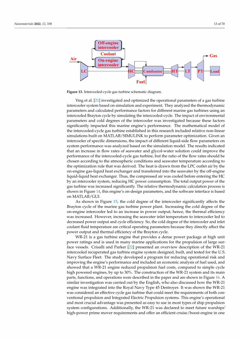
Wen and Dong [20] investigated intercooler heat transfer and fluid flow using numeri-cal analysis. The study was carried out on an intercooled-cycle gas turbine applied to amarine system. The intercooler’s performance was investigated based on its design andoperational parameters. The operation cycle was optimized as a real system. The researchalso included the thermodynamic calculations for the intercooled-cycle gas turbine, whichare important for the design and selection of each component. The main components of thehigh-power marine intercooled-cycle gas turbine consisted of a three-axis gas turbine, heatexchanger, and propeller. LP, HC, combustor, high-pressure turbine (HT), low-pressureturbine (LT), and power turbine (PT) are the main components of the three-axis gas turbine.However, the heat exchanger device consists of two main sections, an on-engine intercooler,and an off-engine intercooler. The system included a reduction gearbox to connect thepropeller to the PT, as shown in Figure 13. The dynamic performance of this kind of engineis mainly dictated by rotor inertia, volume inertia, the thermal inertia of the intercoolersystem, and the relative physical properties of working fluids used. The results showedthat increasing the effectiveness of the intercooler led to a decrease in compressor work.Also, turbine work was decreased due to reduced turbine inlet temperature, decreasingthermal efficiency.
Nanomaterials 2022, 12, 338 13 of 70
Nanomaterials 2022, 12, x FOR PEER REVIEW 13 of 70
intercooler, and an off-engine intercooler. The system included a reduction gearbox to connect the propeller to the PT, as shown in Figure 13. The dynamic performance of this kind of engine is mainly dictated by rotor inertia, volume inertia, the thermal inertia of the intercooler system, and the relative physical properties of working fluids used. The results showed that increasing the effectiveness of the intercooler led to a decrease in com-pressor work. Also, turbine work was decreased due to reduced turbine inlet temperature, decreasing thermal efficiency.
Figure 13. Intercooled-cycle gas turbine schematic diagram.
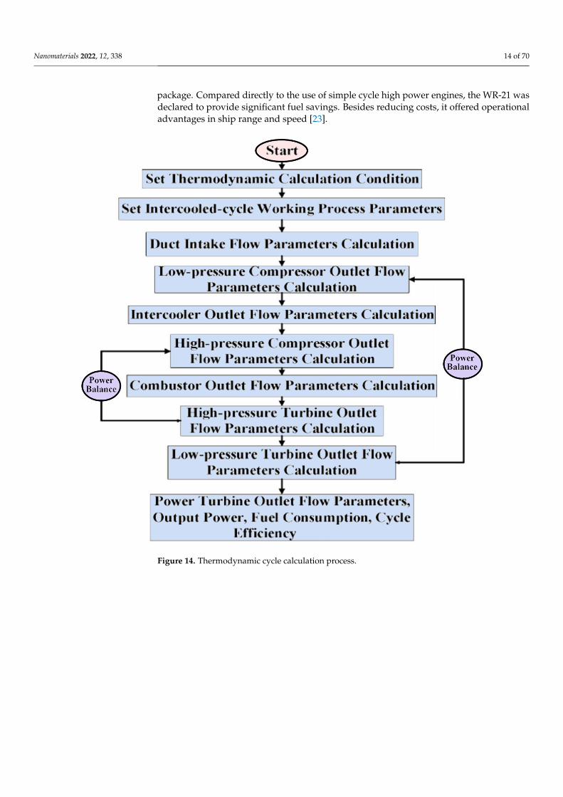
Ying et al. [21] investigated and optimized the operational parameters of a gas tur-bine intercooler system based on simulation and experiment. They analyzed the thermo-dynamic parameters and calculated performance factors for different marine gas turbines using an intercooled Brayton cycle by simulating the intercooled-cycle. The impact of en-vironmental parameters and cold degrees of the intercooler was investigated because these factors significantly impacted this marine engine’s performance. The mathematical model of the intercooled-cycle gas turbine established in this research included relative non-linear simulations built on MATLAB/SIMULINK to perform parameter optimization. Given an intercooler of specific dimensions, the impact of different liquid-side flow pa-rameters on system performance was analyzed based on the simulation model. The results indicated that an increase in flow rates of seawater and glycol-water solution could im-prove the performance of the intercooled-cycle gas turbine, but the ratio of the flow rates should be chosen according to the atmospheric conditions and seawater temperature ac-cording to the optimization rule that was derived. The heat is drawn from the LPC outlet air by the on-engine gas-liquid heat exchanger and transferred into the seawater by the off-engine liquid-liquid heat exchanger. Thus, the compressed air was cooled before en-tering the HC by an intercooler system, reducing HC power consumption. The total out-put power of the gas turbine was increased significantly. The relative thermodynamic cal-culation process is shown in Figure 14, this engine’s on-design parameters, and the soft-ware interface is based on MATLAB/GUI.
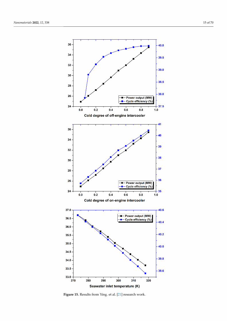
As shown in Figure 15, the cold degree of the intercooler significantly affects the Brayton cycle of the marine gas turbine power plant. Increasing the cold degree of the on-engine intercooler led to an increase in power output; hence, the thermal efficiency was increased. However, increasing the seawater inlet temperature to intercooler led to de-creased power output and cycle efficiency. So, the cold degree of the intercooler and inlet coolant fluid temperature are critical operating parameters because they directly affect the power output and thermal efficiency of the Brayton cycle.
WR-21 is a gas turbine engine that provides a dense power package at high unit power ratings and is used in many marine applications for the propulsion of large surface vessels. Crisalli and Parker [22] presented an overview description of the WR-21 inter-cooled recuperated gas turbine engine system designed, built, and tested for the U.S. Navy Surface Fleet. The study developed a program for reducing operational risk and improv-ing the engine’s performance and included an economic analysis of fuel used, and showed that a WR-21 engine reduced propulsion fuel costs, compared to simple cycle high
Figure 13. Intercooled-cycle gas turbine schematic diagram.
Ying et al. [21] investigated and optimized the operational parameters of a gas turbineintercooler system based on simulation and experiment. They analyzed the thermodynamicparameters and calculated performance factors for different marine gas turbines using anintercooled Brayton cycle by simulating the intercooled-cycle. The impact of environmentalparameters and cold degrees of the intercooler was investigated because these factorssignificantly impacted this marine engine’s performance. The mathematical model ofthe intercooled-cycle gas turbine established in this research included relative non-linearsimulations built on MATLAB/SIMULINK to perform parameter optimization. Given anintercooler of specific dimensions, the impact of different liquid-side flow parameters onsystem performance was analyzed based on the simulation model. The results indicatedthat an increase in flow rates of seawater and glycol-water solution could improve theperformance of the intercooled-cycle gas turbine, but the ratio of the flow rates should bechosen according to the atmospheric conditions and seawater temperature according tothe optimization rule that was derived. The heat is drawn from the LPC outlet air by theon-engine gas-liquid heat exchanger and transferred into the seawater by the off-engineliquid-liquid heat exchanger. Thus, the compressed air was cooled before entering the HCby an intercooler system, reducing HC power consumption. The total output power of thegas turbine was increased significantly. The relative thermodynamic calculation process isshown in Figure 14, this engine’s on-design parameters, and the software interface is basedon MATLAB/GUI.
As shown in Figure 15, the cold degree of the intercooler significantly affects theBrayton cycle of the marine gas turbine power plant. Increasing the cold degree of theon-engine intercooler led to an increase in power output; hence, the thermal efficiencywas increased. However, increasing the seawater inlet temperature to intercooler led todecreased power output and cycle efficiency. So, the cold degree of the intercooler and inletcoolant fluid temperature are critical operating parameters because they directly affect thepower output and thermal efficiency of the Brayton cycle.
WR-21 is a gas turbine engine that provides a dense power package at high unitpower ratings and is used in many marine applications for the propulsion of large sur-face vessels. Crisalli and Parker [22] presented an overview description of the WR-21intercooled recuperated gas turbine engine system designed, built, and tested for the U.S.Navy Surface Fleet. The study developed a program for reducing operational risk andimproving the engine’s performance and included an economic analysis of fuel used, andshowed that a WR-21 engine reduced propulsion fuel costs, compared to simple cyclehigh powered engines, by up to 30%. The construction of the WR-21 system and its mainparts, functions, and operations were described in the paper and are shown in Figure 16. Asimilar investigation was carried out by the English, who also discussed how the WR-21engine was integrated into the Royal Navy Type 45 Destroyer. It was shown the WR-21was considered an effective cycle gas turbine that could meet the requirements of both con-ventional propulsion and Integrated Electric Propulsion systems. This engine’s operationaland most crucial advantage was presented as easy to use in most types of ship propulsionsystem configurations. Additionally, the WR-21 was declared to meet future warships’high-power prime mover requirements and offer an efficient cruise/boost engine in one
Nanomaterials 2022, 12, 338 14 of 70
package. Compared directly to the use of simple cycle high power engines, the WR-21 wasdeclared to provide significant fuel savings. Besides reducing costs, it offered operationaladvantages in ship range and speed [23].
Nanomaterials 2022, 12, x FOR PEER REVIEW 14 of 70
powered engines, by up to 30%. The construction of the WR-21 system and its main parts, functions, and operations were described in the paper and are shown in Figure 16. A sim-ilar investigation was carried out by the English, who also discussed how the WR-21 en-gine was integrated into the Royal Navy Type 45 Destroyer. It was shown the WR-21 was considered an effective cycle gas turbine that could meet the requirements of both con-ventional propulsion and Integrated Electric Propulsion systems. This engine’s opera-tional and most crucial advantage was presented as easy to use in most types of ship pro-pulsion system configurations. Additionally, the WR-21 was declared to meet future war-ships’ high-power prime mover requirements and offer an efficient cruise/boost engine in one package. Compared directly to the use of simple cycle high power engines, the WR-21 was declared to provide significant fuel savings. Besides reducing costs, it offered op-erational advantages in ship range and speed [23].
Figure 14. Thermodynamic cycle calculation process. Figure 14. Thermodynamic cycle calculation process.
Nanomaterials 2022, 12, 338 15 of 70Nanomaterials 2022, 12, x FOR PEER REVIEW 15 of 70
Figure 15. Results from Ying. et al. [21] research work. Figure 15. Results from Ying. et al. [21] research work.
Nanomaterials 2022, 12, 338 16 of 70Nanomaterials 2022, 12, x FOR PEER REVIEW 16 of 70
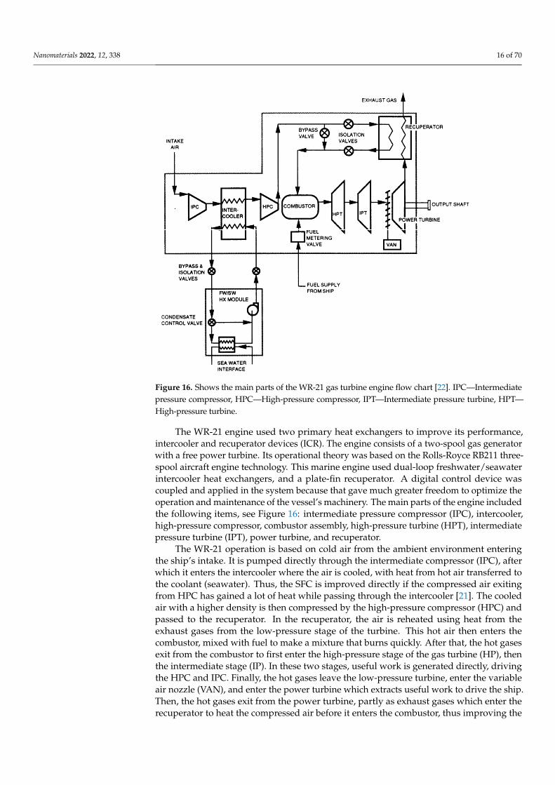
Figure 16. shows the main parts of the WR-21 gas turbine engine flow chart [22]. IPC—Intermediate pressure compressor, HPC—High-pressure compressor, IPT—Intermediate pressure turbine, HPT—High-pressure turbi.ne
The WR-21 engine used two primary heat exchangers to improve its performance, intercooler and recuperator devices (ICR). The engine consists of a two-spool gas genera-tor with a free power turbine. Its operational theory was based on the Rolls-Royce RB211 three-spool aircraft engine technology. This marine engine used dual-loop freshwater/sea-water intercooler heat exchangers, and a plate-fin recuperator. A digital control device was coupled and applied in the system because that gave much greater freedom to opti-mize the operation and maintenance of the vessel’s machinery. The main parts of the en-gine included the following items, see Figure 16: intermediate pressure compressor (IPC), intercooler, high-pressure compressor, combustor assembly, high-pressure turbine (HPT), intermediate pressure turbine (IPT), power turbine, and recuperator.
The WR-21 operation is based on cold air from the ambient environment entering the ship’s intake. It is pumped directly through the intermediate compressor (IPC), after which it enters the intercooler where the air is cooled, with heat from hot air transferred to the coolant (seawater). Thus, the SFC is improved directly if the compressed air exiting from HPC has gained a lot of heat while passing through the intercooler [21]. The cooled air with a higher density is then compressed by the high-pressure compressor (HPC) and passed to the recuperator. In the recuperator, the air is reheated using heat from the ex-haust gases from the low-pressure stage of the turbine. This hot air then enters the com-bustor, mixed with fuel to make a mixture that burns quickly. After that, the hot gases exit from the combustor to first enter the high-pressure stage of the gas turbine (HP), then the intermediate stage (IP). In these two stages, useful work is generated directly, driving the HPC and IPC. Finally, the hot gases leave the low-pressure turbine, enter the variable air nozzle (VAN), and enter the power turbine which extracts useful work to drive the ship. Then, the hot gases exit from the power turbine, partly as exhaust gases which enter the recuperator to heat the compressed air before it enters the combustor, thus improving the
Figure 16. Shows the main parts of the WR-21 gas turbine engine flow chart [22]. IPC—Intermediatepressure compressor, HPC—High-pressure compressor, IPT—Intermediate pressure turbine, HPT—High-pressure turbine.
The WR-21 engine used two primary heat exchangers to improve its performance,intercooler and recuperator devices (ICR). The engine consists of a two-spool gas generatorwith a free power turbine. Its operational theory was based on the Rolls-Royce RB211 three-spool aircraft engine technology. This marine engine used dual-loop freshwater/seawaterintercooler heat exchangers, and a plate-fin recuperator. A digital control device wascoupled and applied in the system because that gave much greater freedom to optimize theoperation and maintenance of the vessel’s machinery. The main parts of the engine includedthe following items, see Figure 16: intermediate pressure compressor (IPC), intercooler,high-pressure compressor, combustor assembly, high-pressure turbine (HPT), intermediatepressure turbine (IPT), power turbine, and recuperator.
The WR-21 operation is based on cold air from the ambient environment enteringthe ship’s intake. It is pumped directly through the intermediate compressor (IPC), afterwhich it enters the intercooler where the air is cooled, with heat from hot air transferred tothe coolant (seawater). Thus, the SFC is improved directly if the compressed air exitingfrom HPC has gained a lot of heat while passing through the intercooler [21]. The cooledair with a higher density is then compressed by the high-pressure compressor (HPC) andpassed to the recuperator. In the recuperator, the air is reheated using heat from theexhaust gases from the low-pressure stage of the turbine. This hot air then enters thecombustor, mixed with fuel to make a mixture that burns quickly. After that, the hot gasesexit from the combustor to first enter the high-pressure stage of the gas turbine (HP), thenthe intermediate stage (IP). In these two stages, useful work is generated directly, drivingthe HPC and IPC. Finally, the hot gases leave the low-pressure turbine, enter the variableair nozzle (VAN), and enter the power turbine which extracts useful work to drive the ship.Then, the hot gases exit from the power turbine, partly as exhaust gases which enter therecuperator to heat the compressed air before it enters the combustor, thus improving the
Nanomaterials 2022, 12, 338 17 of 70
SFC. Using the variable air nozzle (VAN) device in the WR-21 gas turbine helps maintainthe temperature of gases high even after the turbine has extracted power.
A final conclusion presented by Crisalli and Parker [22] of their investigation ofthe WR-21 was that performance requirements could be combined to explain how trade-offs could lead to reaching the best overall combination of cost, performance, reliability,and maintainability.
Arai et al. [24] analyzed the performance of a micro gas turbine system using compu-tational fluid dynamics (CFD). They optimized the operational parameters such as the gasflow inside a compressor and a turbine, to achieve high performance. This included opti-mizing the angle of the impeller blades of the compressor. The results from the numericalanalysis indicated that, in their micro gas turbine, the total pressure ratio of the compressorwas improved by 30% compared to the same system without the change. Optimizing theangle of the impeller blades directly affected the power extracted from the gas, improvingthe power output of the cycle, increasing the thermal efficiency, and decreasing the specificfuel consumption.
The increasing demand for highly efficient, environmentally friendly aero-enginesusing gas turbine Brayton cycle to recover heat from the exhaust gases through a heatexchanger is important. An efficient recuperator for aircraft engines was designed andoptimized by Zhang and Gümmer [25]. The gas turbine blades can work at very hightemperatures, reducing fuel consumption, emission gases, and noise, which are essentialfor rotorcraft power plants. The thermal efficiency reached was more than 60%. Thedesigned recuperator has been manufactured with a ceramic plate-fin heat exchanger,as shown in Figure 17. The recuperator consists of three main parts: a tubular part, aprimary surface, and a plate-fin, a type of recuperator suitable for application to rotorcrafttechnologies. The study concluded that while incorporating recuperators into gas turbinesystems has long been considered for aircraft applications, significant advances in heatexchanger technologies are now possible based on using unique materials such as ceramics,superalloys, and composites, which can work in very high gas temperatures and severethermal environments are available. However, the cost of these materials is relatively highcompared to commercially used stainless steel 347. Concerning cost and creep-strength,modified in coloy alloy 803 and Haynes HR-120 seem to be the best alternatives up to750 ◦C.
Nanomaterials 2022, 12, x FOR PEER REVIEW 17 of 70
SFC. Using the variable air nozzle (VAN) device in the WR-21 gas turbine helps maintain the temperature of gases high even after the turbine has extracted power.
A final conclusion presented by Crisalli and Parker [22] of their investigation of the WR-21 was that performance requirements could be combined to explain how trade-offs could lead to reaching the best overall combination of cost, performance, reliability, and maintainability.
Arai et al. [24] analyzed the performance of a micro gas turbine system using com-putational fluid dynamics (CFD). They optimized the operational parameters such as the gas flow inside a compressor and a turbine, to achieve high performance. This included optimizing the angle of the impeller blades of the compressor. The results from the nu-merical analysis indicated that, in their micro gas turbine, the total pressure ratio of the compressor was improved by 30% compared to the same system without the change. Op-timizing the angle of the impeller blades directly affected the power extracted from the gas, improving the power output of the cycle, increasing the thermal efficiency, and de-creasing the specific fuel consumption.
The increasing demand for highly efficient, environmentally friendly aero-engines using gas turbine Brayton cycle to recover heat from the exhaust gases through a heat exchanger is important. An efficient recuperator for aircraft engines was designed and optimized by Zhang and Gümmer [25]. The gas turbine blades can work at very high temperatures, reducing fuel consumption, emission gases, and noise, which are essential for rotorcraft power plants. The thermal efficiency reached was more than 60%. The de-signed recuperator has been manufactured with a ceramic plate-fin heat exchanger, as shown in Figure 17. The recuperator consists of three main parts: a tubular part, a primary surface, and a plate-fin, a type of recuperator suitable for application to rotorcraft technol-ogies. The study concluded that while incorporating recuperators into gas turbine systems has long been considered for aircraft applications, significant advances in heat exchanger technologies are now possible based on using unique materials such as ceramics, super-alloys, and composites, which can work in very high gas temperatures and severe thermal environments are available. However, the cost of these materials is relatively high com-pared to commercially used stainless steel 347. Concerning cost and creep-strength, mod-ified in coloy alloy 803 and Haynes HR-120 seem to be the best alternatives up to 750 °C.
Figure 17. Cross-section of the recuperated ceramic turboshaft engine [25].
Most designers of gas turbines try to increase the thermal efficiency of the Brayton cycle by decreasing the fuel consumption by using regenerative cycle gas turbines due to their great potential for improving thermal efficiency. Kim and Hwang [23] analyzed the performance of recuperated gas turbines considering engine configuration and
Figure 17. Cross-section of the recuperated ceramic turboshaft engine [25].
Most designers of gas turbines try to increase the thermal efficiency of the Braytoncycle by decreasing the fuel consumption by using regenerative cycle gas turbines due totheir great potential for improving thermal efficiency. Kim and Hwang [23] analyzed theperformance of recuperated gas turbines considering engine configuration and operational
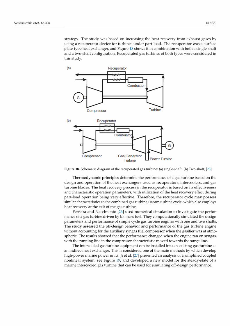
Nanomaterials 2022, 12, 338 18 of 70
strategy. The study was based on increasing the heat recovery from exhaust gases byusing a recuperator device for turbines under part-load. The recuperator was a surfaceplate-type heat exchanger, and Figure 18 shows it in combination with both a single-shaftand a two-shaft configuration. Recuperated gas turbines of both types were considered inthis study.
Nanomaterials 2022, 12, x FOR PEER REVIEW 18 of 70
operational strategy. The study was based on increasing the heat recovery from exhaust gases by using a recuperator device for turbines under part-load. The recuperator was a surface plate-type heat exchanger, and Figure 18 shows it in combination with both a sin-gle-shaft and a two-shaft configuration. Recuperated gas turbines of both types were con-sidered in this study.
Figure 18. Schematic diagram of the recuperated gas turbine: (a) single-shaft. (b) Two-shaft, [23].
Thermodynamic principles determine the performance of a gas turbine based on the design and operation of the heat exchangers used as recuperators, intercoolers, and gas turbine blades. The heat recovery process in the recuperator is based on its effectiveness and characteristic operation parameters, with utilization of the heat recovery effect during part-load operation being very effective. Therefore, the recuperator cycle may possess similar characteristics to the combined gas turbine/steam turbine cycle, which also em-ploys heat recovery at the exit of the gas turbine.
Ferreira and Nascimento [26] used numerical simulation to investigate the perfor-mance of a gas turbine driven by biomass fuel. They computationally simulated the de-sign parameters and performance of simple cycle gas turbine engines with one and two shafts. The study assessed the off-design behavior and performance of the gas turbine engine without accounting for the auxiliary syngas fuel compressor when the gasifier was at atmospheric. The results showed that the performance changed when the engine ran on syngas, with the running line in the compressor characteristic moved towards the surge line.
The intercooled gas turbine equipment can be installed into an existing gas turbine as an indirect heat exchanger. This is considered one of the main methods by which de-velop high-power marine power units. Ji et al. [27] presented an analysis of a simplified coupled nonlinear system, see Figure 19, and developed a new model for the steady-state of a marine intercooled gas turbine that can be used for simulating off-design perfor-mance.
Figure 18. Schematic diagram of the recuperated gas turbine: (a) single-shaft. (b) Two-shaft, [23].
Thermodynamic principles determine the performance of a gas turbine based on thedesign and operation of the heat exchangers used as recuperators, intercoolers, and gasturbine blades. The heat recovery process in the recuperator is based on its effectivenessand characteristic operation parameters, with utilization of the heat recovery effect duringpart-load operation being very effective. Therefore, the recuperator cycle may possesssimilar characteristics to the combined gas turbine/steam turbine cycle, which also employsheat recovery at the exit of the gas turbine.
Ferreira and Nascimento [26] used numerical simulation to investigate the perfor-mance of a gas turbine driven by biomass fuel. They computationally simulated the designparameters and performance of simple cycle gas turbine engines with one and two shafts.The study assessed the off-design behavior and performance of the gas turbine enginewithout accounting for the auxiliary syngas fuel compressor when the gasifier was at atmo-spheric. The results showed that the performance changed when the engine ran on syngas,with the running line in the compressor characteristic moved towards the surge line.
The intercooled gas turbine equipment can be installed into an existing gas turbine asan indirect heat exchanger. This is considered one of the main methods by which develophigh-power marine power units. Ji et al. [27] presented an analysis of a simplified couplednonlinear system, see Figure 19, and developed a new model for the steady-state of amarine intercooled gas turbine that can be used for simulating off-design performance.
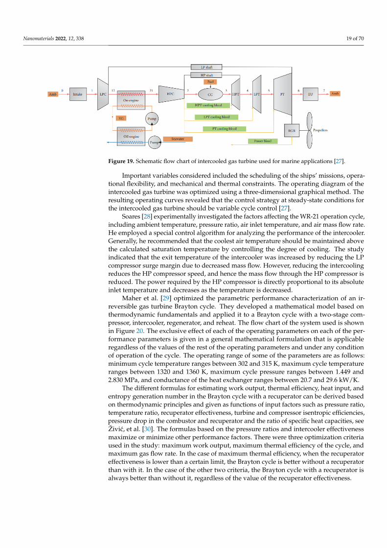
Nanomaterials 2022, 12, 338 19 of 70Nanomaterials 2022, 12, x FOR PEER REVIEW 19 of 70
Figure 19. Schematic flow chart of intercooled gas turbine used for marine applications [27].
Important variables considered included the scheduling of the ships’ missions, oper-ational flexibility, and mechanical and thermal constraints. The operating diagram of the intercooled gas turbine was optimized using a three-dimensional graphical method. The resulting operating curves revealed that the control strategy at steady-state conditions for the intercooled gas turbine should be variable cycle control [27].
Soares [28] experimentally investigated the factors affecting the WR-21 operation cy-cle, including ambient temperature, pressure ratio, air inlet temperature, and air mass flow rate. He employed a special control algorithm for analyzing the performance of the intercooler. Generally, he recommended that the coolest air temperature should be main-tained above the calculated saturation temperature by controlling the degree of cooling. The study indicated that the exit temperature of the intercooler was increased by reducing the LP compressor surge margin due to decreased mass flow. However, reducing the in-tercooling reduces the HP compressor speed, and hence the mass flow through the HP compressor is reduced. The power required by the HP compressor is directly proportional to its absolute inlet temperature and decreases as the temperature is decreased.
Maher et al. [29] optimized the parametric performance characterization of an irre-versible gas turbine Brayton cycle. They developed a mathematical model based on ther-modynamic fundamentals and applied it to a Brayton cycle with a two-stage compressor, intercooler, regenerator, and reheat. The flow chart of the system used is shown in Figure 20. The exclusive effect of each of the operating parameters on each of the performance parameters is given in a general mathematical formulation that is applicable regardless of the values of the rest of the operating parameters and under any condition of operation of the cycle. The operating range of some of the parameters are as follows: minimum cycle temperature ranges between 302 and 315 K, maximum cycle temperature ranges between 1320 and 1360 K, maximum cycle pressure ranges between 1.449 and 2.830 MPa, and con-ductance of the heat exchanger ranges between 20.7 and 29.6 kW/K.
The different formulas for estimating work output, thermal efficiency, heat input, and entropy generation number in the Brayton cycle with a recuperator can be derived based on thermodynamic principles and given as functions of input factors such as pres-sure ratio, temperature ratio, recuperator effectiveness, turbine and compressor isentropic efficiencies, pressure drop in the combustor and recuperator and the ratio of specific heat capacities, see Živić, et al. [30]. The formulas based on the pressure ratios and intercooler effectiveness maximize or minimize other performance factors. There were three optimi-zation criteria used in the study: maximum work output, maximum thermal efficiency of the cycle, and maximum gas flow rate. In the case of maximum thermal efficiency, when the recuperator effectiveness is lower than a certain limit, the Brayton cycle is better with-out a recuperator than with it. In the case of the other two criteria, the Brayton cycle with a recuperator is always better than without it, regardless of the value of the recuperator effectiveness.
Figure 19. Schematic flow chart of intercooled gas turbine used for marine applications [27].
Important variables considered included the scheduling of the ships’ missions, opera-tional flexibility, and mechanical and thermal constraints. The operating diagram of theintercooled gas turbine was optimized using a three-dimensional graphical method. Theresulting operating curves revealed that the control strategy at steady-state conditions forthe intercooled gas turbine should be variable cycle control [27].
Soares [28] experimentally investigated the factors affecting the WR-21 operation cycle,including ambient temperature, pressure ratio, air inlet temperature, and air mass flow rate.He employed a special control algorithm for analyzing the performance of the intercooler.Generally, he recommended that the coolest air temperature should be maintained abovethe calculated saturation temperature by controlling the degree of cooling. The studyindicated that the exit temperature of the intercooler was increased by reducing the LPcompressor surge margin due to decreased mass flow. However, reducing the intercoolingreduces the HP compressor speed, and hence the mass flow through the HP compressor isreduced. The power required by the HP compressor is directly proportional to its absoluteinlet temperature and decreases as the temperature is decreased.
Maher et al. [29] optimized the parametric performance characterization of an ir-reversible gas turbine Brayton cycle. They developed a mathematical model based onthermodynamic fundamentals and applied it to a Brayton cycle with a two-stage com-pressor, intercooler, regenerator, and reheat. The flow chart of the system used is shownin Figure 20. The exclusive effect of each of the operating parameters on each of the per-formance parameters is given in a general mathematical formulation that is applicableregardless of the values of the rest of the operating parameters and under any conditionof operation of the cycle. The operating range of some of the parameters are as follows:minimum cycle temperature ranges between 302 and 315 K, maximum cycle temperatureranges between 1320 and 1360 K, maximum cycle pressure ranges between 1.449 and2.830 MPa, and conductance of the heat exchanger ranges between 20.7 and 29.6 kW/K.
The different formulas for estimating work output, thermal efficiency, heat input, andentropy generation number in the Brayton cycle with a recuperator can be derived basedon thermodynamic principles and given as functions of input factors such as pressure ratio,temperature ratio, recuperator effectiveness, turbine and compressor isentropic efficiencies,pressure drop in the combustor and recuperator and the ratio of specific heat capacities, seeŽivic, et al. [30]. The formulas based on the pressure ratios and intercooler effectivenessmaximize or minimize other performance factors. There were three optimization criteriaused in the study: maximum work output, maximum thermal efficiency of the cycle, andmaximum gas flow rate. In the case of maximum thermal efficiency, when the recuperatoreffectiveness is lower than a certain limit, the Brayton cycle is better without a recuperatorthan with it. In the case of the other two criteria, the Brayton cycle with a recuperator isalways better than without it, regardless of the value of the recuperator effectiveness.
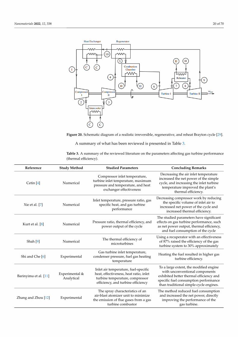
Nanomaterials 2022, 12, 338 20 of 70Nanomaterials 2022, 12, x FOR PEER REVIEW 20 of 70
Figure 20. Schematic diagram of a realistic irreversible, regenerative, and reheat Brayton cycle [29].
A summary of what has been reviewed is presented in Table 3.
Table 3. A summary of the reviewed literature on the parameters affecting gas turbine performance (thermal efficiency).
Reference Study Method Studied Parameters Concluding Remarks
Cetin [4] Numerical
Compressor inlet temperature, turbine inlet temperature, maximum pressure and temperature, and heat
exchanger effectiveness
Decreasing the air inlet temperature increased the net power of the simple cycle, and increasing the inlet turbine temperature improved the plant’s
thermal efficiency.
Xie et al. [7] Numerical Inlet temperature, pressure ratio, gas
specific heat, and gas turbine performance
Decreasing compressor work by reducing the specific volume of inlet air to increased net power
of the cycle and increased thermal efficiency.
Kurt et al. [8] Numerical Pressure ratio, thermal efficiency, and power output of the cycle
The studied parameters have significant effects on gas turbine performance, such as net power
output, thermal efficiency, and fuel consumption of the cycle
Shah [9] Numerical The thermal efficiency of
microturbines
Using a recuperator with an effectiveness of 87% raised the efficiency of the gas turbine system to
30% approximately
Shi and Che [6]
Experimental Gas turbine inlet temperature,
condenser pressure, fuel gas heating temperature
Heating the fuel resulted in higher gas turbine efficiency.
Barinyima et al. [11]
Experimental & Analytical
Inlet air temperature, fuel-specific heat, effectiveness, heat ratio, inlet turbine temperature, compressor efficiency, and turbine efficiency
To a large extent, the modified engine with unconventional components exhibited better
thermal efficiency and specific fuel consumption performance than traditional simple-cycle engines.
Zhang and Zhou [12]
Experimental
The spray characteristics of an air-blast atomizer unit to minimize the
emission of flue gases from a gas turbine combustor
The method reduced fuel consumption and increased the net power, directly improving the
performance of the gas turbine.
Figure 20. Schematic diagram of a realistic irreversible, regenerative, and reheat Brayton cycle [29].
A summary of what has been reviewed is presented in Table 3.
Table 3. A summary of the reviewed literature on the parameters affecting gas turbine performance(thermal efficiency).
Reference Study Method Studied Parameters Concluding Remarks
Cetin [4] Numerical
Compressor inlet temperature,turbine inlet temperature, maximumpressure and temperature, and heat
exchanger effectiveness
Decreasing the air inlet temperatureincreased the net power of the simplecycle, and increasing the inlet turbine
temperature improved the plant’sthermal efficiency.
Xie et al. [7] NumericalInlet temperature, pressure ratio, gas
specific heat, and gas turbineperformance
Decreasing compressor work by reducingthe specific volume of inlet air to
increased net power of the cycle andincreased thermal efficiency.
Kurt et al. [8] Numerical Pressure ratio, thermal efficiency, andpower output of the cycle
The studied parameters have significanteffects on gas turbine performance, suchas net power output, thermal efficiency,
and fuel consumption of the cycle
Shah [9] Numerical The thermal efficiency ofmicroturbines
Using a recuperator with an effectivenessof 87% raised the efficiency of the gasturbine system to 30% approximately
Shi and Che [6] ExperimentalGas turbine inlet temperature,
condenser pressure, fuel gas heatingtemperature
Heating the fuel resulted in higher gasturbine efficiency.
Barinyima et al. [11] Experimental &Analytical
Inlet air temperature, fuel-specificheat, effectiveness, heat ratio, inletturbine temperature, compressorefficiency, and turbine efficiency
To a large extent, the modified enginewith unconventional components
exhibited better thermal efficiency andspecific fuel consumption performancethan traditional simple-cycle engines.
Zhang and Zhou [12] Experimental
The spray characteristics of anair-blast atomizer unit to minimize
the emission of flue gases from a gasturbine combustor
The method reduced fuel consumptionand increased the net power, directly
improving the performance of thegas turbine.
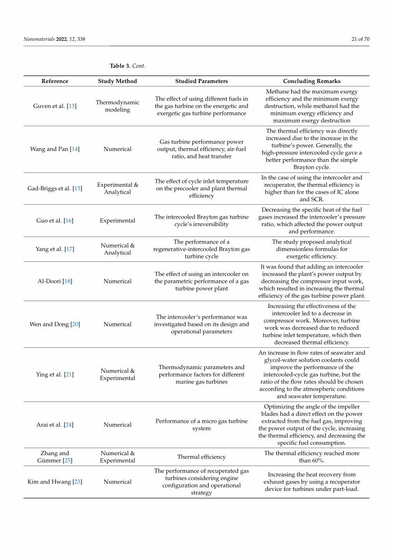
Nanomaterials 2022, 12, 338 21 of 70
Table 3. Cont.
Reference Study Method Studied Parameters Concluding Remarks
Guven et al. [13] Thermodynamicmodeling
The effect of using different fuels inthe gas turbine on the energetic andexergetic gas turbine performance
Methane had the maximum exergyefficiency and the minimum exergydestruction, while methanol had the
minimum exergy efficiency andmaximum exergy destruction
Wang and Pan [14] NumericalGas turbine performance power
output, thermal efficiency, air-fuelratio, and heat transfer
The thermal efficiency was directlyincreased due to the increase in the
turbine’s power. Generally, thehigh-pressure intercooled cycle gave a
better performance than the simpleBrayton cycle.
Gad-Briggs et al. [15] Experimental &Analytical
The effect of cycle inlet temperatureon the precooler and plant thermal
efficiency
In the case of using the intercooler andrecuperator, the thermal efficiency ishigher than for the cases of IC alone
and SCR.
Guo et al. [16] Experimental The intercooled Brayton gas turbinecycle’s irreversibility
Decreasing the specific heat of the fuelgases increased the intercooler’s pressure
ratio, which affected the power outputand performance.
Yang et al. [17] Numerical &Analytical
The performance of aregenerative-intercooled Brayton gas
turbine cycle
The study proposed analyticaldimensionless formulas for
exergetic efficiency.
Al-Doori [18] NumericalThe effect of using an intercooler onthe parametric performance of a gas
turbine power plant
It was found that adding an intercoolerincreased the plant’s power output bydecreasing the compressor input work,
which resulted in increasing the thermalefficiency of the gas turbine power plant.
Wen and Dong [20] NumericalThe intercooler’s performance was
investigated based on its design andoperational parameters
Increasing the effectiveness of theintercooler led to a decrease in
compressor work. Moreover, turbinework was decreased due to reduced
turbine inlet temperature, which thendecreased thermal efficiency.
Ying et al. [21] Numerical &Experimental
Thermodynamic parameters andperformance factors for different
marine gas turbines
An increase in flow rates of seawater andglycol-water solution coolants could
improve the performance of theintercooled-cycle gas turbine, but the
ratio of the flow rates should be chosenaccording to the atmospheric conditions
and seawater temperature.
Arai et al. [24] Numerical Performance of a micro gas turbinesystem
Optimizing the angle of the impellerblades had a direct effect on the powerextracted from the fuel gas, improving
the power output of the cycle, increasingthe thermal efficiency, and decreasing the
specific fuel consumption.
Zhang andGümmer [25]
Numerical &Experimental Thermal efficiency The thermal efficiency reached more
than 60%.
Kim and Hwang [23] Numerical
The performance of recuperated gasturbines considering engine
configuration and operationalstrategy
Increasing the heat recovery fromexhaust gases by using a recuperatordevice for turbines under part-load.
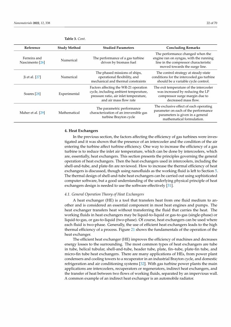
Nanomaterials 2022, 12, 338 22 of 70
Table 3. Cont.
Reference Study Method Studied Parameters Concluding Remarks
Ferreira andNascimento [26] Numerical The performance of a gas turbine
driven by biomass fuel
The performance changed when theengine ran on syngas, with the running
line in the compressor characteristicmoved towards the surge line.
Ji et al. [27] NumericalThe phased missions of ships,
operational flexibility, andmechanical and thermal constraints
The control strategy at steady-stateconditions for the intercooled gas turbine
should be a variable cycle control.
Soares [28] Experimental
Factors affecting the WR-21 operationcycle, including ambient temperature,pressure ratio, air inlet temperature,
and air mass flow rate
The exit temperature of the intercoolerwas increased by reducing the LPcompressor surge margin due to
decreased mass flow.
Maher et al. [29] MathematicalThe parametric performance
characterization of an irreversible gasturbine Brayton cycle
The exclusive effect of each operatingparameter on each of the performance
parameters is given in a generalmathematical formulation.
4. Heat Exchangers
In the previous section, the factors affecting the efficiency of gas turbines were inves-tigated and it was shown that the presence of an intercooler and the condition of the airentering the turbine affect turbine efficiency. One way to increase the efficiency of a gasturbine is to reduce the inlet air temperature, which can be done by intercoolers, whichare, essentially, heat exchangers. This section presents the principles governing the generaloperation of heat exchangers. Then the heat exchangers used in intercoolers, including theshell-and-tube, and plate-fin are reviewed. How to increase the thermal efficiency of heatexchangers is discussed, though using nanofluids as the working fluid is left to Section 5.The thermal design of shell-and-tube heat exchangers can be carried out using sophisticatedcomputer software, but a good understanding of the underlying physical principle of heatexchangers design is needed to use the software effectively [31].
4.1. General Operation Theory of Heat Exchangers
A heat exchanger (HE) is a tool that transfers heat from one fluid medium to an-other and is considered an essential component in most heat engines and pumps. Theheat exchanger transfers heat without transferring the fluid that carries the heat. Theworking fluids in heat exchangers may be liquid-to-liquid or gas-to-gas (single-phase) orliquid-to-gas, or gas-to-liquid (two-phase). Of course, heat exchangers can be used whereeach fluid is two-phase. Generally, the use of efficient heat exchangers leads to the highthermal efficiency of a process. Figure 21 shows the fundamentals of the operation of theheat exchanger.
The efficient heat exchanger (HE) improves the efficiency of machines and decreasesenergy losses to the surrounding. The most common types of heat exchangers are tubein tube, helical tubular, shell-and-tube, header tube, plate, fin–tube, plate-fin tube, andmicro-fin tube heat exchangers. There are many applications of HEs, from power plantcondensers and cooling towers to a recuperator in an industrial Brayton cycle, and domesticrefrigeration and air conditioning systems [32]. With gas turbine power plants the mainapplications are intercoolers, recuperators or regenerators, indirect heat exchangers, andthe transfer of heat between two flows of working fluids, separated by an impervious wall.A common example of an indirect heat exchanger is an automobile radiator.

Nanomaterials 2022, 12, 338 23 of 70
Nanomaterials 2022, 12, x FOR PEER REVIEW 22 of 70
Soares [28] Experimental
Factors affecting the WR-21 operation cycle, including ambient
temperature, pressure ratio, air inlet temperature, and air mass flow rate
The exit temperature of the intercooler was increased by reducing the LP compressor surge
margin due to decreased mass flow.
Maher et al. [29]
Mathematical The parametric performance
characterization of an irreversible gas turbine Brayton cycle
The exclusive effect of each operating parameter on each of the performance parameters is given in
a general mathematical formulation.
4. Heat Exchangers In the previous section, the factors affecting the efficiency of gas turbines were inves-
tigated and it was shown that the presence of an intercooler and the condition of the air entering the turbine affect turbine efficiency. One way to increase the efficiency of a gas turbine is to reduce the inlet air temperature, which can be done by intercoolers, which are, essentially, heat exchangers. This section presents the principles governing the gen-eral operation of heat exchangers. Then the heat exchangers used in intercoolers, includ-ing the shell-and-tube, and plate-fin are reviewed. How to increase the thermal efficiency of heat exchangers is discussed, though using nanofluids as the working fluid is left to Section 5. The thermal design of shell-and-tube heat exchangers can be carried out using sophisticated computer software, but a good understanding of the underlying physical principle of heat exchangers design is needed to use the software effectively [31].
4.1. General Operation Theory of Heat Exchangers A heat exchanger (HE) is a tool that transfers heat from one fluid medium to another
and is considered an essential component in most heat engines and pumps. The heat ex-changer transfers heat without transferring the fluid that carries the heat. The working fluids in heat exchangers may be liquid-to-liquid or gas-to-gas (single-phase) or liquid-to-gas, or gas-to-liquid (two-phase). Of course, heat exchangers can be used where each fluid is two-phase. Generally, the use of efficient heat exchangers leads to the high thermal ef-ficiency of a process. Figure 21 shows the fundamentals of the operation of the heat ex-changer.
Figure 21. How a simple heat exchanger works. Figure 21. How a simple heat exchanger works.
The energy consumption in most energy conversion machines is based on their per-formance using HEs. Generally, the energy consumption of a heat engine can be reducedby selecting an efficient heat exchanger to be used with it. For example, if the boiler’sthermal efficiency in an industrial steam power plant increased 0.5%, this would saveconsiderable amounts of conventional fuel (oil) [33]. There are many studies on the analysisand design of heat exchangers, including heat transfer due to condensation or evaporation.Most investigations have been concerned with the design and simulation of different typesof heat exchangers such as tube in tube and shell-and-tube. The aim was to improvethe performance of the heat exchangers by such means as using fins and micro-fins. Thetheoretical simulations were compared to experimental data from numerous articles. Thesedata were used to assess the theoretical models and analytical solutions for linear andnon-linear heat transfer problems. Such design and development of finned–tube in tubecoil heat exchanger were carried out by, for example, Kakac et al. [34].
In most HE designs, the temperature gradient, the rato of temperature difference towall thickness (∆T/∆x), is critical. The temperature gradient determines the heat transferrate and heat flux through the HE. In the given ambient conditions, the correct selectionof temperature gradient and pressure drop across the HE maximizes the heat exchangedbetween the two sides of a heat exchanger, between the two working mediums [34].
The heat transfer area also has a big effect on the performance of the HE. The totalheat transfer rate depends directly on the surface area of the HE separating the two fluids.Increasing heat transfer area will invariably increase the heat transfer rate. Thus, in heatexchangers maximizing the overall heat transfer rate means increasing the heat transferarea, which can be achieved by, for example, installing fins on heat exchanger tubes. Such anarrangement permits compact heat exchangers with very large heat transfer areas per unitvolume, with a corresponding reduction in volume, weight, footprint, support structureneeded, and even cost. In addition, there could be an improved process design, plantlayout, and processing conditions, together with lower fluid inventory [35].
Generally, gas-to-liquid heat exchangers are compact. The heat transfer surface has asurface area density greater than 700 m2/m3 and greater than 400 m2/m3 when operatingin a liquid or phase-change stream. The hydraulic diameter, Dh, defined as 4Ao /P (whereAo is the minimum free-flow area on one fluid side of a heat exchanger, and P is the wettedperimeter of flow passages on that side [32], can be less than 6mm (1/4 in.) for gas streams.
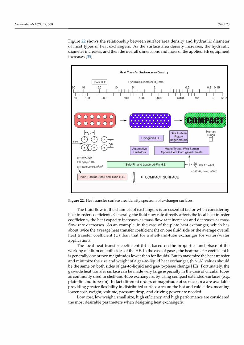
Nanomaterials 2022, 12, 338 24 of 70
Figure 22 shows the relationship between surface area density and hydraulic diameterof most types of heat exchangers. As the surface area density increases, the hydraulicdiameter increases, and then the overall dimensions and mass of the applied HE equipmentincreases [35].
Nanomaterials 2022, 12, x FOR PEER REVIEW 24 of 70
Figure 22. Heat transfer surface area density spectrum of exchanger surfaces.
The local heat transfer coefficient (h) is based on the properties and phase of the working medium on both sides of the HE. In the case of gases, the heat transfer coefficient h is generally one or two magnitudes lower than for liquids. But to maximize the heat transfer and minimize the size and weight of a gas-to-liquid heat exchanger, (h × A) values should be the same on both sides of gas-to-liquid and gas-to-phase change HEs. Fortu-nately, the gas-side heat transfer surface can be made very large especially in the case of circular tubes as commonly used in shell-and-tube exchangers, by using compact ex-tended-surfaces (e.g., plate-fin and tube-fin). In fact different orders of magnitude of sur-face area are available providing greater flexibility in distributed surface area on the hot and cold sides, meaning lower cost, weight, volume, pressure drop, and driving power are needed.
Low cost, low weight, small size, high efficiency, and high performance are consid-ered the most desirable parameters when designing heat exchangers.
4.2. Shell-and-Tube Heat Exchangers A shell-and-tube heat exchanger is a device in which heat is transferred from one
fluid stream to another via an intervening solid wall and is a common design of HE. It is widely used in many applications, from large chemical processes to air conditioning sys-tems. Shell-and-tube HEs are commonly used in gas turbine power plants as recuperators, consisting of a tube bundle enclosed in a cylindrical shell, see Figure 23. The principal components of a shell-and-tube heat exchanger are shell, tubes, channel, channel cover, baffles, and tube sheets. One fluid flow through the tubes, and a second flows through the shell, and heat is transferred between the two [36].
The shell-and-tube heat exchanger consists of a series of tubes within a larger volume (typically cylindrical but can be any shape). Ling et al. [36] have presented design guide-lines covering the selection and sizing methods for heat exchangers, listing all the
Figure 22. Heat transfer surface area density spectrum of exchanger surfaces.
The fluid flow in the channels of exchangers is an essential factor when consideringheat transfer coefficients. Generally, the fluid flow rate directly affects the local heat transfercoefficients, the heat capacity increases as mass flow rate increases and decreases as massflow rate decreases. As an example, in the case of the plate heat exchanger, which hasabout twice the average heat transfer coefficient (h) on one fluid side or the average overallheat transfer coefficient (U) than that for a shell-and-tube exchanger for water/waterapplications.
The local heat transfer coefficient (h) is based on the properties and phase of theworking medium on both sides of the HE. In the case of gases, the heat transfer coefficient his generally one or two magnitudes lower than for liquids. But to maximize the heat transferand minimize the size and weight of a gas-to-liquid heat exchanger, (h × A) values shouldbe the same on both sides of gas-to-liquid and gas-to-phase change HEs. Fortunately, thegas-side heat transfer surface can be made very large especially in the case of circular tubesas commonly used in shell-and-tube exchangers, by using compact extended-surfaces (e.g.,plate-fin and tube-fin). In fact different orders of magnitude of surface area are availableproviding greater flexibility in distributed surface area on the hot and cold sides, meaninglower cost, weight, volume, pressure drop, and driving power are needed.
Low cost, low weight, small size, high efficiency, and high performance are consideredthe most desirable parameters when designing heat exchangers.
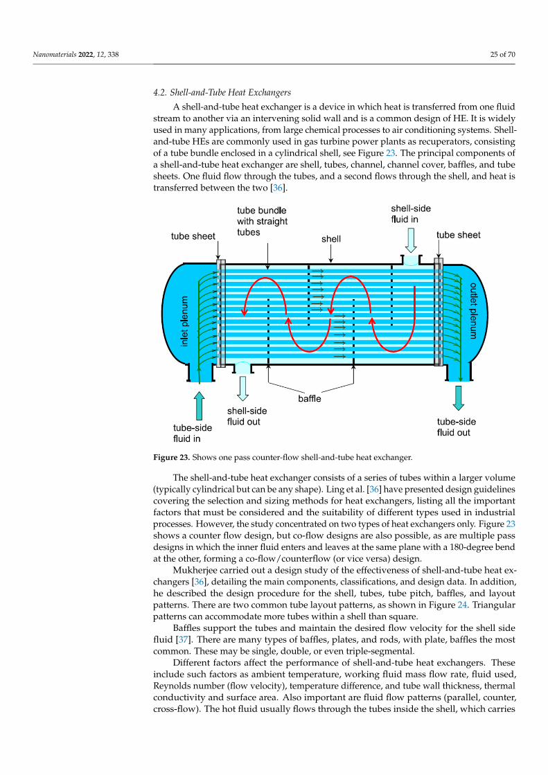
Nanomaterials 2022, 12, 338 25 of 70
4.2. Shell-and-Tube Heat Exchangers
A shell-and-tube heat exchanger is a device in which heat is transferred from one fluidstream to another via an intervening solid wall and is a common design of HE. It is widelyused in many applications, from large chemical processes to air conditioning systems. Shell-and-tube HEs are commonly used in gas turbine power plants as recuperators, consistingof a tube bundle enclosed in a cylindrical shell, see Figure 23. The principal components ofa shell-and-tube heat exchanger are shell, tubes, channel, channel cover, baffles, and tubesheets. One fluid flow through the tubes, and a second flows through the shell, and heat istransferred between the two [36].
Nanomaterials 2022, 12, x FOR PEER REVIEW 25 of 70
important factors that must be considered and the suitability of different types used in industrial processes. However, the study concentrated on two types of heat exchangers only. Figure 23 shows a counter flow design, but co-flow designs are also possible, as are multiple pass designs in which the inner fluid enters and leaves at the same plane with a 180-degree bend at the other, forming a co-flow/counterflow (or vice versa) design.
Figure 23. Shows one pass counter-flow shell-and-tube heat exchanger.
Mukherjee carried out a design study of the effectiveness of shell-and-tube heat ex-changers [36], detailing the main components, classifications, and design data. In addition, he described the design procedure for the shell, tubes, tube pitch, baffles, and layout pat-terns. There are two common tube layout patterns, as shown in Figure 24. Triangular pat-terns can accommodate more tubes within a shell than square.
Baffles support the tubes and maintain the desired flow velocity for the shell side fluid [37]. There are many types of baffles, plates, and rods, with plate, baffles the most common. These may be single, double, or even triple-segmental.
Different factors affect the performance of shell-and-tube heat exchangers. These in-clude such factors as ambient temperature, working fluid mass flow rate, fluid used, Reynolds number (flow velocity), temperature difference, and tube wall thickness, ther-mal conductivity and surface area. Also important are fluid flow patterns (parallel, coun-ter, cross-flow). The hot fluid usually flows through the tubes inside the shell, which car-ries the flow of cooler fluid in the opposite direction (counter flow). Ambient conditions and operational factors may affect the heat transfer coefficients in real heat exchangers.
An important parameter to be taken into consideration is temperature profile distor-tion. Practically, it has been noted that there are leakage and bypass streams in shell-and-tube HEs with less efficient heat transfer than the main cross-flow stream, reducing the overall heat transfer rate and lowering the temperature profile, as shown in Figure 25. The temperature profiles of the baffle-hole-to-tube leakage, shell-to-bundle leakage, and pass-partition bypass streams will be based on their respective flow leakage fractions, and the fractional heat-transfer area encountered [38].
Figure 23. Shows one pass counter-flow shell-and-tube heat exchanger.
The shell-and-tube heat exchanger consists of a series of tubes within a larger volume(typically cylindrical but can be any shape). Ling et al. [36] have presented design guidelinescovering the selection and sizing methods for heat exchangers, listing all the importantfactors that must be considered and the suitability of different types used in industrialprocesses. However, the study concentrated on two types of heat exchangers only. Figure 23shows a counter flow design, but co-flow designs are also possible, as are multiple passdesigns in which the inner fluid enters and leaves at the same plane with a 180-degree bendat the other, forming a co-flow/counterflow (or vice versa) design.
Mukherjee carried out a design study of the effectiveness of shell-and-tube heat ex-changers [36], detailing the main components, classifications, and design data. In addition,he described the design procedure for the shell, tubes, tube pitch, baffles, and layoutpatterns. There are two common tube layout patterns, as shown in Figure 24. Triangularpatterns can accommodate more tubes within a shell than square.
Baffles support the tubes and maintain the desired flow velocity for the shell sidefluid [37]. There are many types of baffles, plates, and rods, with plate, baffles the mostcommon. These may be single, double, or even triple-segmental.
Different factors affect the performance of shell-and-tube heat exchangers. Theseinclude such factors as ambient temperature, working fluid mass flow rate, fluid used,Reynolds number (flow velocity), temperature difference, and tube wall thickness, thermalconductivity and surface area. Also important are fluid flow patterns (parallel, counter,cross-flow). The hot fluid usually flows through the tubes inside the shell, which carries
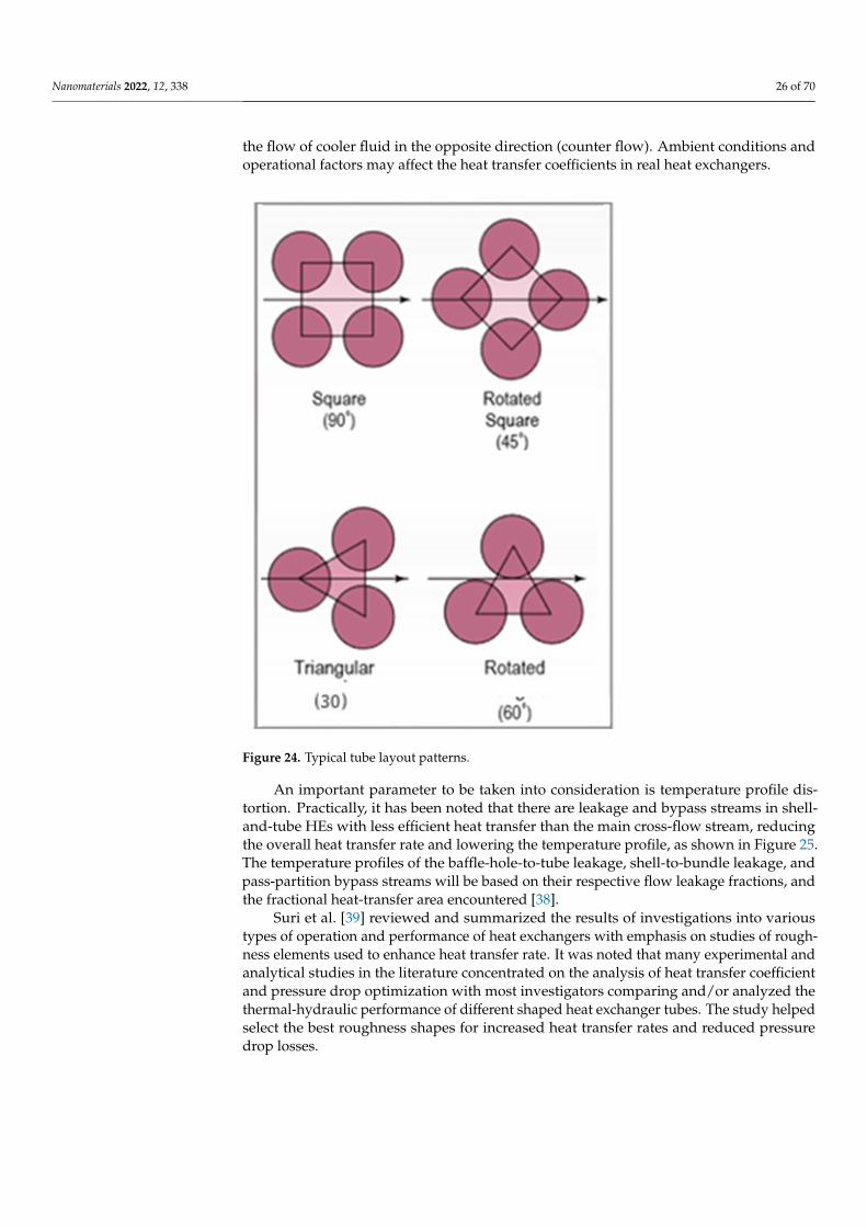
Nanomaterials 2022, 12, 338 26 of 70
the flow of cooler fluid in the opposite direction (counter flow). Ambient conditions andoperational factors may affect the heat transfer coefficients in real heat exchangers.
Nanomaterials 2022, 12, x FOR PEER REVIEW 26 of 70
Figure 24. Typical tube layout patterns.
Figure 25. Temperature profile distortion factor due to bypass and leakage.
Figure 24. Typical tube layout patterns.
An important parameter to be taken into consideration is temperature profile dis-tortion. Practically, it has been noted that there are leakage and bypass streams in shell-and-tube HEs with less efficient heat transfer than the main cross-flow stream, reducingthe overall heat transfer rate and lowering the temperature profile, as shown in Figure 25.The temperature profiles of the baffle-hole-to-tube leakage, shell-to-bundle leakage, andpass-partition bypass streams will be based on their respective flow leakage fractions, andthe fractional heat-transfer area encountered [38].
Suri et al. [39] reviewed and summarized the results of investigations into varioustypes of operation and performance of heat exchangers with emphasis on studies of rough-ness elements used to enhance heat transfer rate. It was noted that many experimental andanalytical studies in the literature concentrated on the analysis of heat transfer coefficientand pressure drop optimization with most investigators comparing and/or analyzed thethermal-hydraulic performance of different shaped heat exchanger tubes. The study helpedselect the best roughness shapes for increased heat transfer rates and reduced pressuredrop losses.
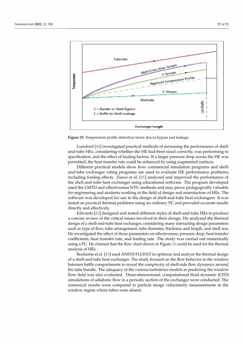
Nanomaterials 2022, 12, 338 27 of 70
Nanomaterials 2022, 12, x FOR PEER REVIEW 26 of 70
Figure 24. Typical tube layout patterns.
Figure 25. Temperature profile distortion factor due to bypass and leakage. Figure 25. Temperature profile distortion factor due to bypass and leakage.
Lunsford [40] investigated practical methods of increasing the performance of shell-and-tube HEs, considering whether the HE had been sized correctly, was performing tospecification, and the effect of fouling factors. If a larger pressure drop across the HE waspermitted, the heat transfer rate could be enhanced by using augmented surfaces.
Different practical models show how commercial simulation programs and shell-and-tube exchanger rating programs are used to evaluate HE performance problems,including fouling effects. Zueco et al. [41] analyzed and improved the performance ofthe shell-and-tube heat exchanger using educational software. The program developedused the LMTD and effectiveness NTU methods and may prove pedagogically valuablefor engineering and students working in the field of design and manufacture of HEs. Thesoftware was developed for use in the design of shell-and-tube heat exchangers. It wastested on practical thermal problems using an ordinary PC and provided accurate resultsdirectly and effectively.
Edwards [42] designed and tested different styles of shell-and-tube HEs to producea concise review of the critical issues involved in their design. He analyzed the thermaldesign of a shell-and-tube heat exchanger, considering many interacting design parameterssuch as type of flow, tube arrangement, tube diameter, thickness and length, and shell size.He investigated the effect of those parameters on effectiveness, pressure drop, heat transfercoefficients, heat transfer rate, and fouling rate. The study was carried out numericallyusing a PC. He claimed that the flow chart shown in Figure 26 could be used for the thermalanalysis of HEs.
Bouhairie et al. [43] used ANSYS FLUENT to optimize and analyze the thermal designof a shell-and-tube heat exchanger. The study focused on the flow behavior in the windowbetween baffle compartments to reveal the complexity of shell-side flow dynamics aroundthe tube bundle. The adequacy of the various turbulence models in predicting the windowflow field was also evaluated. Three-dimensional, computational fluid dynamic (CFD)simulations of adiabatic flow in a periodic section of the exchanger were conducted. Thenumerical results were compared to particle image velocimetry measurements in thewindow region where tubes were absent.

Nanomaterials 2022, 12, 338 28 of 70
Nanomaterials 2022, 12, x FOR PEER REVIEW 27 of 70
Suri et al. [39] reviewed and summarized the results of investigations into various types of operation and performance of heat exchangers with emphasis on studies of roughness elements used to enhance heat transfer rate. It was noted that many experi-mental and analytical studies in the literature concentrated on the analysis of heat transfer coefficient and pressure drop optimization with most investigators comparing and/or an-alyzed the thermal-hydraulic performance of different shaped heat exchanger tubes. The study helped select the best roughness shapes for increased heat transfer rates and re-duced pressure drop losses.
Lunsford [40] investigated practical methods of increasing the performance of shell-and-tube HEs, considering whether the HE had been sized correctly, was performing to specification, and the effect of fouling factors. If a larger pressure drop across the HE was permitted, the heat transfer rate could be enhanced by using augmented surfaces.
Different practical models show how commercial simulation programs and shell-and-tube exchanger rating programs are used to evaluate HE performance problems, in-cluding fouling effects. Zueco et al. [41] analyzed and improved the performance of the shell-and-tube heat exchanger using educational software. The program developed used the LMTD and effectiveness NTU methods and may prove pedagogically valuable for engineering and students working in the field of design and manufacture of HEs. The software was developed for use in the design of shell-and-tube heat exchangers. It was tested on practical thermal problems using an ordinary PC and provided accurate results directly and effectively.
Edwards [42] designed and tested different styles of shell-and-tube HEs to produce a concise review of the critical issues involved in their design. He analyzed the thermal design of a shell-and-tube heat exchanger, considering many interacting design parame-ters such as type of flow, tube arrangement, tube diameter, thickness and length, and shell size. He investigated the effect of those parameters on effectiveness, pressure drop, heat transfer coefficients, heat transfer rate, and fouling rate. The study was carried out numer-ically using a PC. He claimed that the flow chart shown in Figure 26 could be used for the thermal analysis of HEs.
Figure 26. Shows a flow chart for the thermal design of HEs.
Ghaith et al. [44] investigated how to enhance the thermal design of a shell-and-tubeheat exchanger. The study aimed to improve the performance of an industrial shell-and-tube heat exchanger used for cooling raw natural gas, to provide an optimum and reliablethermal design of a single-shelled finned tube HE, to replace the existing two shell-and-tube HE due to space limitations in the plant. The thermal design was based on theeffectiveness-NTU method. The shell-side and tube-side overall heat transfer coefficientswere determined using the Bell-Delaware method and Dittus-Boelter correlation, respec-tively. The results showed that the critical area to provide a thermal duty of 1.4 MW wasabout 1132 m2 with tube-side and shell-side heat transfer coefficients of 950 W/m2K and495 W/m2K, respectively. The results generated from the mathematical model, usingHTRI software, showed a good match in terms of the heat transfer area and tube-side heattransfer coefficient.
Wan et al. [45] investigated thermal failures generated in the tube-to-tube sheet jointsof a shell-and-tube heat exchanger, which are greatly affected by residual weld stresses.To ensure structural integrity, it is very important to predict and decrease the residualstresses in the joints between tubes and tube sheets of HEs. X-ray diffraction and finiteelement method were combined to analyze the residual stress distribution in the tube-to-tube sheet joints and showed that large tensile residual stresses above yield strengthcould be generated. The residual stresses at the bottom surface and the edge of the tubesheet are relatively small, even becoming compressive. The residual stresses increase asthe heat input increases. The duplex welding method was recommended to decrease theresidual stress.
Wang et al. [46] conducted research to provide a state-of-the-art development of threekinds of surface heat exchangers: shell-and-tube with helical baffles, primary surface, andair-cooled as used in large air-cooled systems. The research highlighted that shell-and-tubeheat exchangers that dominate the market are available in many configurations, includingexchangers with segmental baffles. However, there were drawbacks associated with thisgeometry, including inefficiencies, leading to the development of the shell-and-tube heat

Nanomaterials 2022, 12, 338 29 of 70
exchanger with helical baffles. The basic principle of this design is relatively simple,involving circular or elliptical sector-shaped plates which are arranged in a pseudo-helicalbaffle system. In this setup, each baffle occupies one quadrant of the heat exchanger shellcross-section area, with an angle of inclination towards the central axis of the shell, resultingin a helix flow path for the working fluid.
4.3. Plate-Fin Heat Exchangers
Examples of compact heat exchangers are plate-fin, tube-fin, and rotary regeneratorsused with gas flow as one or both fluids. Today, printed-circuit heat exchangers are exam-ples of compact heat exchangers used with liquid flows. Compact heat exchangers are notnecessarily of small bulk and mass, but are much smaller than conventional heat exchang-ers of corresponding performance because they incorporate surfaces of high-surface-areadensity. Compact heat exchangers are widely-used when there is a need to achieve a largeheat transfer rate per unit volume. The small flow passages invariably mean the flow willbe laminar [47].
The mass flow through plate-fin heat exchangers must be modified and optimizedaccording to the operating conditions and specifications of the heat exchanger used. In-creasing the flow rate of cold fluid in the plate-fin tube heat exchanger leads to an increasein both heat transfer rate and pressure drop across the heat exchanger. Using a heatexchanger with offset strip fin geometry is considered one device to obtain the highestperforming heat exchange surface, but this is complex to manufacture due to the verydifficult brazing process.
In the case of using highly compact HEs, the final shape must be designed to achieveuniform flow distribution through a large number of passages [35]. It should have a largefrontal surface area, low flow length, and low header path. When selecting compact HEs,there are some important design and operating factors to be considered: invariably, at leastone of the fluids will be a gas which means these heat exchangers have a low Dh, the fluidpumping power, and the pressure drop (∆p) are very important as this will affect heattransfer rate and power consumption of the system, temperatures are limited compared toshell-and-tube exchangers. The working fluids must be clean and noncorrosive becausea big problem with compact heat exchangers is fouling, the formation and accumulationof scale on the paths of fluids, leading to decreased heat transfer rate and an increase inthe pumping force required. Fouling is also significant in plate-tube fin heat exchangers,especially with very fine circular and noncircular fins. Highly flammable or toxic fluidsmust be avoided due to the possibility of leakage. Non-fouling fluids, such as clean air orgases, light hydrocarbons, and refrigerants, are recommended for these HEs. The problemis compounded because mechanical cleaning is very difficult. Chemical cleaning is onepractical solution, as is thermal baking with subsequent rinsing, particularly in the caseof very small units. This precludes the use of compact plate-fin heat exchangers in heavyfouling conditions.
The selection of proper materials for constructing a recuperator is very importantbecause of the required heat transfer, mechanical expansion, chemical reactions, etc., thatoccur when working at very high temperatures. The effect of oxidization of water va-por in the recuperator plays a crucial role affecting the heat transfer coefficient of theHE. Pint et al. [48] studied experimentally the effect of the water vapor found in exhaustgases on the oxidation resistance of materials commonly used for recuperators, stainlesssteel (SS) grade 321, Inconel 625, Haynes 214, and PM2000. The study found that SS321 hadrelatively low oxidation resistance at a temperature of 700 ◦C and recommended the use ofstainless steel material of HE only for hot fluid inlet temperatures of less than about 675 ◦C.The report recommended using very much more expensive superalloys for manufacturingthose heat recuperators used at very high temperatures or used with water on either sideto minimize overall operating costs.
Lara-Curzio et al. [49] designed and built a recuperator that operated at a temperatureof 843 ◦C and was used with a micro-turbine of 60 kW rated output. Different materials
Nanomaterials 2022, 12, 338 30 of 70
and alloys were tested and subjected to high thermal stresses, and the material selectedwas a superalloy of aluminum mica, i.e., the final material selected for manufacturingmicroturbines was a ceramic.
There is a strong relationship between the material of a heat exchanger and its per-formance. For HEs operating at more normal conditions, the high thermal conductancerequired demands the use of materials such as copper, aluminum, iron alloys, etc., whichhave both the high thermal conductivity and mechanical strength required. These materi-als should also be resistant to chemical degradation and wear. Cost and manufacturingprocesses are two important factors that affect the selection of materials from which HEsare made.
The plate HE can be used with gas/liquid working fluids. The gas medium may bepure air, and the liquid can be water, oil, or any other liquid. Fabio et al. [50] modeledand designed ceramic plate HEs with special features for use in different applications,manufacturing the HEs using a welding process. These ceramic plate HEs achieved a veryhigh thermal effectiveness, reaching 95%. The investigation also explored working fluidsand recommended that the working fluid should be of low viscosity to decrease the pumppower needed for circulation. However, it was also found that the very smooth materialused for the plate HE decreased the pressure drop and reduced flow distribution problems,allowing a working fluid of greater viscosity.
Modern plate HEs, as described above, are assembled as a single unit, forming criss-cross flow channels of intricate geometry, characterized by the formation of contact pointsbetween the opposite walls located at corrugation crossings. The effectiveness of such aplate HE is due to the plates’ corrugated form, which has a major impact on heat transferand hydraulic behavior. Arsenyeva et al. [51] investigated the design of an efficient plate HEby analyzing heat transfer within channels of complex geometry typical of those formed bythin metal plates with the aim of predicting the influence of pressure drop, temperature, andheat load on the performance of the HE. It was found that the geometry of the corrugationshad a major impact on the heat transfer process. The study concluded that it is difficult toachieve optimal performance with the plates currently on the market and as such, furtherresearch is required into the design of these exchangers.
Bichnevicius et al. [52] investigated the performance of a louvered plate-fin heatexchanger, comparing traditionally manufactured and additively manufactured HEs basedon the same design. The additively manufactured HEs were produced by a laser-basedpowder bed fusion process, also known as selective laser melting. The study foundadditively manufactured HEs varied in performance even when printed using the samedigital model. It was concluded that there is a need to allow for variation in surfaceroughness, geometric deviations, and other potential defects when designing HEs, resultingin improved thermal performance of future heat exchangers produced in this way.
Plate-fin geometry for maximizing heat transfer through HEs was investigated byKarvinen and Karvinen [53]. They presented a new method for determining plate-fingeometry for maximizing heat flux. The method is based on approximate analyticalsolutions of conjugated heat transfer correlations. The result showed that certain thermaland geometrical properties of the fin and the flow are very important factors due to theirdirect effect on the size of the HE. The values of heat transfer coefficients were given forrectangular, convex parabolic, triangular, and concave parabolic fin shapes for natural andforced convection, including laminar and turbulent boundary layers. It was concluded thatthere was no need to evaluate convection heat transfer coefficients separately because theyare already included in these variables. Easy-to-use design rules were presented for findingthe geometry of fixed volume fins that gave the maximum heat transfer.
The heat transfer performance and space efficiency of compact heat exchangers withan emphasis on wavy fin exchangers was investigated by Kim and Rhee [54]. These heatexchangers typically have high thermal performance due to the dynamic flow patternimposed by the fin geometry. This is influenced by the corrugation angle, which affectsthe heat transfer effectiveness and the pressure drop depending on the flow, which can be
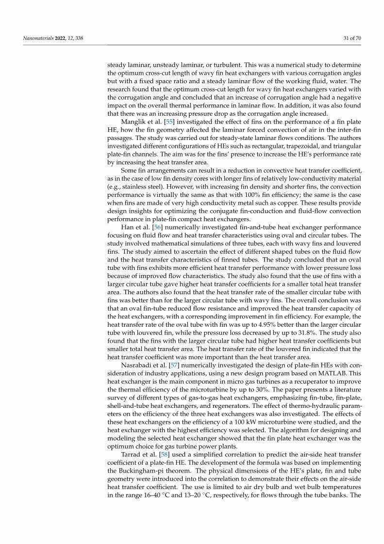
Nanomaterials 2022, 12, 338 31 of 70
steady laminar, unsteady laminar, or turbulent. This was a numerical study to determinethe optimum cross-cut length of wavy fin heat exchangers with various corrugation anglesbut with a fixed space ratio and a steady laminar flow of the working fluid, water. Theresearch found that the optimum cross-cut length for wavy fin heat exchangers varied withthe corrugation angle and concluded that an increase of corrugation angle had a negativeimpact on the overall thermal performance in laminar flow. In addition, it was also foundthat there was an increasing pressure drop as the corrugation angle increased.
Manglik et al. [55] investigated the effect of fins on the performance of a fin plateHE, how the fin geometry affected the laminar forced convection of air in the inter-finpassages. The study was carried out for steady-state laminar flows conditions. The authorsinvestigated different configurations of HEs such as rectangular, trapezoidal, and triangularplate-fin channels. The aim was for the fins’ presence to increase the HE’s performance rateby increasing the heat transfer area.
Some fin arrangements can result in a reduction in convective heat transfer coefficient,as in the case of low fin density cores with longer fins of relatively low-conductivity material(e.g., stainless steel). However, with increasing fin density and shorter fins, the convectionperformance is virtually the same as that with 100% fin efficiency; the same is the casewhen fins are made of very high conductivity metal such as copper. These results providedesign insights for optimizing the conjugate fin-conduction and fluid-flow convectionperformance in plate-fin compact heat exchangers.
Han et al. [56] numerically investigated fin-and-tube heat exchanger performancefocusing on fluid flow and heat transfer characteristics using oval and circular tubes. Thestudy involved mathematical simulations of three tubes, each with wavy fins and louveredfins. The study aimed to ascertain the effect of different shaped tubes on the fluid flowand the heat transfer characteristics of finned tubes. The study concluded that an ovaltube with fins exhibits more efficient heat transfer performance with lower pressure lossbecause of improved flow characteristics. The study also found that the use of fins with alarger circular tube gave higher heat transfer coefficients for a smaller total heat transferarea. The authors also found that the heat transfer rate of the smaller circular tube withfins was better than for the larger circular tube with wavy fins. The overall conclusion wasthat an oval fin-tube reduced flow resistance and improved the heat transfer capacity ofthe heat exchangers, with a corresponding improvement in fin efficiency. For example, theheat transfer rate of the oval tube with fin was up to 4.95% better than the larger circulartube with louvered fin, while the pressure loss decreased by up to 31.8%. The study alsofound that the fins with the larger circular tube had higher heat transfer coefficients butsmaller total heat transfer area. The heat transfer rate of the louvered fin indicated that theheat transfer coefficient was more important than the heat transfer area.
Nasrabadi et al. [57] numerically investigated the design of plate-fin HEs with con-sideration of industry applications, using a new design program based on MATLAB. Thisheat exchanger is the main component in micro gas turbines as a recuperator to improvethe thermal efficiency of the microturbine by up to 30%. The paper presents a literaturesurvey of different types of gas-to-gas heat exchangers, emphasizing fin-tube, fin-plate,shell-and-tube heat exchangers, and regenerators. The effect of thermo-hydraulic param-eters on the efficiency of the three heat exchangers was also investigated. The effects ofthese heat exchangers on the efficiency of a 100 kW microturbine were studied, and theheat exchanger with the highest efficiency was selected. The algorithm for designing andmodeling the selected heat exchanger showed that the fin plate heat exchanger was theoptimum choice for gas turbine power plants.
Tarrad et al. [58] used a simplified correlation to predict the air-side heat transfercoefficient of a plate-fin HE. The development of the formula was based on implementingthe Buckingham-pi theorem. The physical dimensions of the HE’s plate, fin and tubegeometry were introduced into the correlation to demonstrate their effects on the air-sideheat transfer coefficient. The use is limited to air dry bulb and wet bulb temperaturesin the range 16–40 ◦C and 13–20 ◦C, respectively, for flows through the tube banks. The
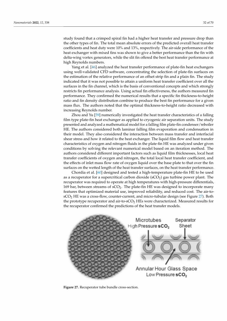
Nanomaterials 2022, 12, 338 32 of 70
study found that a crimped spiral fin had a higher heat transfer and pressure drop thanthe other types of fin. The total mean absolute errors of the predicted overall heat transfercoefficients and heat duty were 10% and 13%, respectively. The air-side performance of theheat exchanger with mixed fins was shown to give a better performance than the fin withdelta-wing vortex generators, while the slit fin offered the best heat transfer performance athigh Reynolds numbers.
Yang et al. [46] analyzed the heat transfer performance of plate-fin heat exchangersusing well-validated CFD software, concentrating the selection of plate-fin surfaces onthe estimation of the relative performance of an offset strip fin and a plain fin. The studyindicated that it was not possible to attain a uniform heat transfer coefficient over all thesurfaces in the fin channel, which is the basis of conventional concepts and which stronglyrestricts fin performance analysis. Using actual fin effectiveness, the authors measured finperformance. They confirmed the numerical results that a specific fin thickness-to-heightratio and fin density distribution combine to produce the best fin performance for a givenmass flux. The authors noted that the optimal thickness-to-height ratio decreased withincreasing Reynolds number.
Zhou and Yu [59] numerically investigated the heat transfer characteristics of a fallingfilm type plate-fin heat exchanger as applied to cryogenic air separation units. The studypresented and analyzed a mathematical model for a falling film plate-fin condenser/reboilerHE. The authors considered both laminar falling film evaporation and condensation intheir model. They also considered the interaction between mass transfer and interfacialshear stress and how it related to the heat exchanger. The liquid film flow and heat transfercharacteristics of oxygen and nitrogen fluids in the plate-fin HE was analyzed under givenconditions by solving the relevant numerical model based on an iteration method. Theauthors considered different important factors such as liquid film thicknesses, local heattransfer coefficients of oxygen and nitrogen, the total local heat transfer coefficient, andthe effects of inlet mass flow rate of oxygen liquid over the base plate to that over the finsurfaces on the wetted length of the heat transfer surfaces, on the heat transfer performance.
Chordia et al. [60] designed and tested a high-temperature plate-fin HE to be usedas a recuperator for a supercritical carbon dioxide (sCO2) gas turbine power plant. Therecuperator was required to operate at high temperatures with high-pressure differentials,169 bar, between streams of sCO2. The plate-fin HE was designed to incorporate manyfeatures that optimized material use, improved reliability, and reduced cost. The air-to-sCO2 HE was a cross-flow, counter-current, and micro-tubular design (see Figure 27). Boththe prototype recuperator and air-to-sCO2 HEs were characterized. Measured results forthe recuperator confirmed the predictions of the heat transfer models.
Nanomaterials 2022, 12, x FOR PEER REVIEW 32 of 70
mass flux. The authors noted that the optimal thickness-to-height ratio decreased with increasing Reynolds number.
Zhou and Yu [59] numerically investigated the heat transfer characteristics of a fall-ing film type plate-fin heat exchanger as applied to cryogenic air separation units. The study presented and analyzed a mathematical model for a falling film plate-fin conden-ser/reboiler HE. The authors considered both laminar falling film evaporation and con-densation in their model. They also considered the interaction between mass transfer and interfacial shear stress and how it related to the heat exchanger. The liquid film flow and heat transfer characteristics of oxygen and nitrogen fluids in the plate-fin HE was ana-lyzed under given conditions by solving the relevant numerical model based on an itera-tion method. The authors considered different important factors such as liquid film thick-nesses, local heat transfer coefficients of oxygen and nitrogen, the total local heat transfer coefficient, and the effects of inlet mass flow rate of oxygen liquid over the base plate to that over the fin surfaces on the wetted length of the heat transfer surfaces, on the heat transfer performance.
Chordia et al. [60] designed and tested a high-temperature plate-fin HE to be used as a recuperator for a supercritical carbon dioxide (sCO2) gas turbine power plant. The recu-perator was required to operate at high temperatures with high-pressure differentials, 169 bar, between streams of sCO2. The plate-fin HE was designed to incorporate many fea-tures that optimized material use, improved reliability, and reduced cost. The air-to-sCO2 HE was a cross-flow, counter-current, and micro-tubular design (see Figure 27). Both the prototype recuperator and air-to-sCO2 HEs were characterized. Measured results for the recuperator confirmed the predictions of the heat transfer models.
Figure 27. Recuperator tube bundle cross-section.
Abou Elmaaty et al. [61] reviewed plate HEs used as recuperators with gas turbines. A good HE has a high heat transfer rate at low pumping power at minimum cost. Figure 28 shows a typical structure of a plate-fin HE with chevron plates. The paper discussed the integration of different considerations such as the structure of the plate HE, thermal performance, heat transfer enhancement, and the advantages and limitations of plate HEs. The authors concluded that the plate-fin HE worked efficiently in both single and two-phase flows, though two-phase flow still requires considerable further research. These authors also discussed the performance of corrugated plate HEs when using nano-fluids, see Section 5 below. Also, the paper summarized how this type of heat exchanger is widely used in many different engineering fields due to its simplicity in assembly/disassembly, ease of maintenance, and greater flexibility than other types of heat exchangers. Because its heat transfer area and cooling flow can be increased or decreased easily, it is commonly used for enlargement and upgrading. One important application is as an intercooler and/or recuperator in gas turbine systems.
Figure 27. Recuperator tube bundle cross-section.

Nanomaterials 2022, 12, 338 33 of 70
Abou Elmaaty et al. [61] reviewed plate HEs used as recuperators with gas turbines. Agood HE has a high heat transfer rate at low pumping power at minimum cost. Figure 28shows a typical structure of a plate-fin HE with chevron plates. The paper discussedthe integration of different considerations such as the structure of the plate HE, thermalperformance, heat transfer enhancement, and the advantages and limitations of plate HEs.The authors concluded that the plate-fin HE worked efficiently in both single and two-phase flows, though two-phase flow still requires considerable further research. Theseauthors also discussed the performance of corrugated plate HEs when using nano-fluids,see Section 5 below. Also, the paper summarized how this type of heat exchanger is widelyused in many different engineering fields due to its simplicity in assembly/disassembly,ease of maintenance, and greater flexibility than other types of heat exchangers. Because itsheat transfer area and cooling flow can be increased or decreased easily, it is commonlyused for enlargement and upgrading. One important application is as an intercooler and/orrecuperator in gas turbine systems.
Nanomaterials 2022, 12, x FOR PEER REVIEW 33 of 70
Figure 28. Typical structure of plate-fin heat exchanger with chevron plates [61].
A summary of what has been discussed in this section is presented in Table 4.
Table 4. A summary of the reviewed literature on the parameters affecting the performance of dif-ferent HEs.
Reference HE Type Studied Parameters Remarks Mukherjee
[38] Shell-and-
tube Thermal effectiveness of shell-
and-tube heat exchangers A design procedure for the shell, tubes, tube pitch, baffles,
and layout patterns was presented.
Suri et al. [39] Reviewed
different HEs Roughness elements used to
enhance heat transfer rate
It was noted that many experimental and analytical studies in the literature concentrated on the analysis of heat transfer coefficient and pressure drop optimization.
Lunsford [40] Shell-and-
tube
Methods of increasing the performance of shell-and-tube
HEs
If a larger pressure drop across the HE was permitted, augmented surfaces could be used to enhance heat
transfer. Zueco et al.
[41] Shell-and-
tube Performance factor Software developed for for use in the design of shell-and-
tube heat exchangers
Edwards [42] Shell-and-
tube
Thermal design parameters such as type of flow, tube
arrangement, tube diameter, thickness and length, and shell
size
The effect of the studied parameters on effectiveness, pressure drop, heat transfer coefficients, heat transfer rate,
and fouling rate were reported.
Bouhairie et al. [43]
Shell-and-tube
Thermal design parameters The study focused on the flow behavior in the window
between baffle compartments to reveal the complexity of shell-side flow dynamics around the tube bundle.
Ghaith et al. [44]
Shell-and-tube
How to enhance the thermal design of a shell-and-tube heat
exchanger
The results showed that the critical area to provide a thermal duty of 1.4 MW was about 1132 m2 with tube-side and shell-side heat transfer coefficients of 950 W/m2K and
495 W/m2K, respectively.
Wan et al. [45]
Shell-and-tube
Thermal failures generated in the tube-to-tube sheet joints of
a shell-and-tube heat exchanger
The results showed that large tensile residual stresses above yield strength could be generated in the tube-to-tubesheet joints. The residual stresses at the bottom surface and
the edge of the tube sheet are relatively small, even becoming compressive.
Pint et al. [48] Plate-Fin The effect of the water vapor found in exhaust gases on the
oxidation resistance of
The report recommended the use of expensive superalloys for manufacturing heat recuperators used at very high
temperatures or used with water on either side to minimize overall operating costs.
Figure 28. Typical structure of plate-fin heat exchanger with chevron plates [61].
A summary of what has been discussed in this section is presented in Table 4.
Table 4. A summary of the reviewed literature on the parameters affecting the performance ofdifferent HEs.
Reference HE Type Studied Parameters Remarks
Mukherjee [38] Shell-and-tube Thermal effectiveness ofshell-and-tube heat exchangers
A design procedure for the shell, tubes, tubepitch, baffles, and layout patterns was
presented.
Suri et al. [39] Revieweddifferent HEs
Roughness elements used toenhance heat transfer rate
It was noted that many experimental andanalytical studies in the literature
concentrated on the analysis of heat transfercoefficient and pressure drop optimization.
Lunsford [40] Shell-and-tube Methods of increasing theperformance of shell-and-tube HEs
If a larger pressure drop across the HE waspermitted, augmented surfaces could be
used to enhance heat transfer.
Zueco et al. [41] Shell-and-tube Performance factor Software developed for for use in the designof shell-and-tube heat exchangers
Edwards [42] Shell-and-tube
Thermal design parameters such astype of flow, tube arrangement,
tube diameter, thickness and length,and shell size
The effect of the studied parameters oneffectiveness, pressure drop, heat transfercoefficients, heat transfer rate, and fouling
rate were reported.

Nanomaterials 2022, 12, 338 34 of 70
Table 4. Cont.
Reference HE Type Studied Parameters Remarks
Bouhairie et al. [43] Shell-and-tube Thermal design parameters
The study focused on the flow behavior inthe window between baffle compartments to
reveal the complexity of shell-side flowdynamics around the tube bundle.
Ghaith et al. [44] Shell-and-tube How to enhance the thermal designof a shell-and-tube heat exchanger
The results showed that the critical area toprovide a thermal duty of 1.4 MW was about1132 m2 with tube-side and shell-side heat
transfer coefficients of 950 W/m2K and495 W/m2K, respectively.
Wan et al. [45] Shell-and-tubeThermal failures generated in the
tube-to-tube sheet joints of ashell-and-tube heat exchanger
The results showed that large tensile residualstresses above yield strength could be
generated in the tube-to-tube sheet joints.The residual stresses at the bottom surfaceand the edge of the tube sheet are relatively
small, even becoming compressive.
Pint et al. [48] Plate-Fin
The effect of the water vapor foundin exhaust gases on the oxidationresistance of materials commonly
used for recuperators
The report recommended the use ofexpensive superalloys for manufacturing
heat recuperators used at very hightemperatures or used with water on eitherside to minimize overall operating costs.
Lara-Curzio et al. [49] Plate-Fin Design of a recuperator thatoperates at high temperatures
Different materials were tested, and the finalmaterial recommended for manufacturing
microturbines is a ceramic.
Fabio et al. [50] Plate-Fin Types of working fluids
It was found that the working fluid shouldbe of low viscosity to decrease the pump
power needed for circulation, that using verysmooth material for the plate HE decreased
the pressure drop and reduced flowdistribution problems, allowing the use of a
working fluid of greater viscosity.
Arsenyeva et al. [51] Plate-Fin Analyzing heat transfer withinchannels of complex geometry
The study concluded that it is difficult toachieve optimal performance with the platescurrently on the market and as such, further
research is required into the design ofthese exchangers.
Bichnevicius et al. [52] Plate-Fin
The performance of a louveredplate-fin heat exchanger, comparing
traditionally manufactured andadditively manufactured HEs based
on the same design.
The study found additively manufacturedHEs varied in performance even whenprinted using the same digital model.
Karvinen andKarvinen [53] Plate-Fin Effects of geometry to maximise
heat transfer
A new method for determining plate-fingeometry for maximizing heat flux
was presented.
Kim and Rhee [54] Plate-FinThe heat transfer performance and
space efficiency of compactheat exchangers
The research found that the optimumcross-cut length for wavy fin heat exchangers
varied with the corrugation angle; anincrease of corrugation angle had a negativeimpact on the overall thermal performance in
laminar flow.
Manglik et al. [55] Plate-Fin The effect of pins on theperformance of a plate-fin HE
Increasing fin density and using shorter finsproduced a convection performance that is
virtually the same as that with 100%fin efficiency.
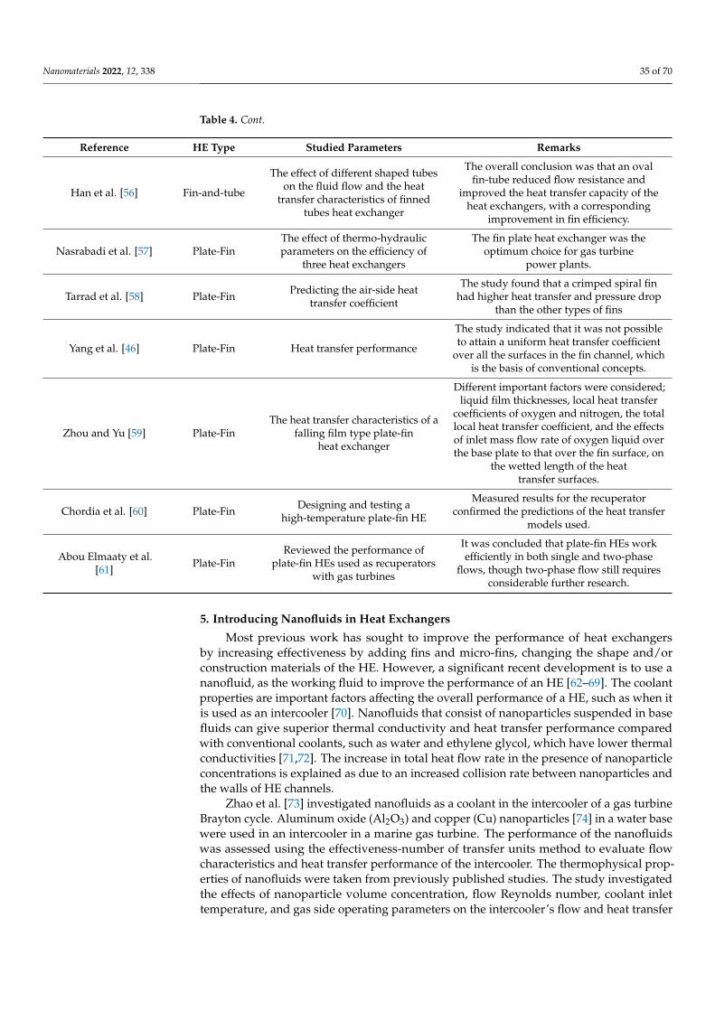
Nanomaterials 2022, 12, 338 35 of 70
Table 4. Cont.
Reference HE Type Studied Parameters Remarks
Han et al. [56] Fin-and-tube
The effect of different shaped tubeson the fluid flow and the heat
transfer characteristics of finnedtubes heat exchanger
The overall conclusion was that an ovalfin-tube reduced flow resistance and
improved the heat transfer capacity of theheat exchangers, with a corresponding
improvement in fin efficiency.
Nasrabadi et al. [57] Plate-FinThe effect of thermo-hydraulicparameters on the efficiency of
three heat exchangers
The fin plate heat exchanger was theoptimum choice for gas turbine
power plants.
Tarrad et al. [58] Plate-Fin Predicting the air-side heattransfer coefficient
The study found that a crimped spiral finhad higher heat transfer and pressure drop
than the other types of fins
Yang et al. [46] Plate-Fin Heat transfer performance
The study indicated that it was not possibleto attain a uniform heat transfer coefficient
over all the surfaces in the fin channel, whichis the basis of conventional concepts.
Zhou and Yu [59] Plate-FinThe heat transfer characteristics of a
falling film type plate-finheat exchanger
Different important factors were considered;liquid film thicknesses, local heat transfer
coefficients of oxygen and nitrogen, the totallocal heat transfer coefficient, and the effectsof inlet mass flow rate of oxygen liquid overthe base plate to that over the fin surface, on
the wetted length of the heattransfer surfaces.
Chordia et al. [60] Plate-Fin Designing and testing ahigh-temperature plate-fin HE
Measured results for the recuperatorconfirmed the predictions of the heat transfer
models used.
Abou Elmaaty et al.[61] Plate-Fin
Reviewed the performance ofplate-fin HEs used as recuperators
with gas turbines
It was concluded that plate-fin HEs workefficiently in both single and two-phase
flows, though two-phase flow still requiresconsiderable further research.
5. Introducing Nanofluids in Heat Exchangers
Most previous work has sought to improve the performance of heat exchangersby increasing effectiveness by adding fins and micro-fins, changing the shape and/orconstruction materials of the HE. However, a significant recent development is to use ananofluid, as the working fluid to improve the performance of an HE [62–69]. The coolantproperties are important factors affecting the overall performance of a HE, such as when itis used as an intercooler [70]. Nanofluids that consist of nanoparticles suspended in basefluids can give superior thermal conductivity and heat transfer performance comparedwith conventional coolants, such as water and ethylene glycol, which have lower thermalconductivities [71,72]. The increase in total heat flow rate in the presence of nanoparticleconcentrations is explained as due to an increased collision rate between nanoparticles andthe walls of HE channels.
Zhao et al. [73] investigated nanofluids as a coolant in the intercooler of a gas turbineBrayton cycle. Aluminum oxide (Al2O3) and copper (Cu) nanoparticles [74] in a water basewere used in an intercooler in a marine gas turbine. The performance of the nanofluidswas assessed using the effectiveness-number of transfer units method to evaluate flowcharacteristics and heat transfer performance of the intercooler. The thermophysical prop-erties of nanofluids were taken from previously published studies. The study investigatedthe effects of nanoparticle volume concentration, flow Reynolds number, coolant inlettemperature, and gas side operating parameters on the intercooler’s flow and heat transfer
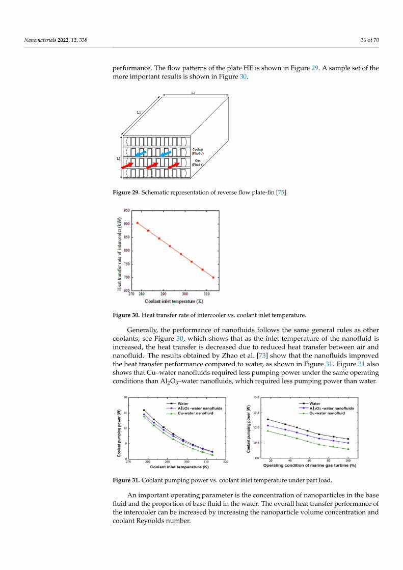
Nanomaterials 2022, 12, 338 36 of 70
performance. The flow patterns of the plate HE is shown in Figure 29. A sample set of themore important results is shown in Figure 30.
Nanomaterials 2022, 12, x FOR PEER REVIEW 35 of 70
Chordia et al. [60]
Plate-Fin Designing and testing a high-temperature plate-fin HE
Measured results for the recuperator confirmed the predictions of the heat transfer models used.
Abou Elmaaty et al.
[61] Plate-Fin
Reviewed the performance of plate-fin HEs used as
recuperators with gas turbines
It was concluded that plate-fin HEs work efficiently in both single and two-phase flows, though two-phase flow
still requires considerable further research.
5. Introducing Nanofluids in Heat Exchangers Most previous work has sought to improve the performance of heat exchangers by
increasing effectiveness by adding fins and micro-fins, changing the shape and/or con-struction materials of the HE. However, a significant recent development is to use a nanofluid, as the working fluid to improve the performance of an HE [62–69]. The coolant properties are important factors affecting the overall performance of a HE, such as when it is used as an intercooler [70]. Nanofluids that consist of nanoparticles suspended in base fluids can give superior thermal conductivity and heat transfer performance compared with conventional coolants, such as water and ethylene glycol, which have lower thermal conductivities [71,72]. The increase in total heat flow rate in the presence of nanoparticle concentrations is explained as due to an increased collision rate between nanoparticles and the walls of HE channels.
Zhao et al. [73] investigated nanofluids as a coolant in the intercooler of a gas turbine Brayton cycle. Aluminum oxide (Al2O3) and copper (Cu) nanoparticles [74] in a water base were used in an intercooler in a marine gas turbine. The performance of the nanofluids was assessed using the effectiveness-number of transfer units method to evaluate flow characteristics and heat transfer performance of the intercooler. The thermophysical prop-erties of nanofluids were taken from previously published studies. The study investigated the effects of nanoparticle volume concentration, flow Reynolds number, coolant inlet temperature, and gas side operating parameters on the intercooler’s flow and heat transfer performance. The flow patterns of the plate HE is shown in Figure 29. A sample set of the more important results is shown in Figure 30 .
Figure 29. Schematic representation of reverse flow plate-fin [75].
Figure 29. Schematic representation of reverse flow plate-fin [75].
Nanomaterials 2022, 12, x FOR PEER REVIEW 35 of 70
Chordia et al. [60]
Plate-Fin Designing and testing a high-temperature plate-fin HE
Measured results for the recuperator confirmed the predictions of the heat transfer models used.
Abou Elmaaty et al.
[61] Plate-Fin
Reviewed the performance of plate-fin HEs used as
recuperators with gas turbines
It was concluded that plate-fin HEs work efficiently in both single and two-phase flows, though two-phase flow
still requires considerable further research.
5. Introducing Nanofluids in Heat Exchangers Most previous work has sought to improve the performance of heat exchangers by
increasing effectiveness by adding fins and micro-fins, changing the shape and/or con-struction materials of the HE. However, a significant recent development is to use a nanofluid, as the working fluid to improve the performance of an HE [62–69]. The coolant properties are important factors affecting the overall performance of a HE, such as when it is used as an intercooler [70]. Nanofluids that consist of nanoparticles suspended in base fluids can give superior thermal conductivity and heat transfer performance compared with conventional coolants, such as water and ethylene glycol, which have lower thermal conductivities [71,72]. The increase in total heat flow rate in the presence of nanoparticle concentrations is explained as due to an increased collision rate between nanoparticles and the walls of HE channels.
Zhao et al. [73] investigated nanofluids as a coolant in the intercooler of a gas turbine Brayton cycle. Aluminum oxide (Al2O3) and copper (Cu) nanoparticles [74] in a water base were used in an intercooler in a marine gas turbine. The performance of the nanofluids was assessed using the effectiveness-number of transfer units method to evaluate flow characteristics and heat transfer performance of the intercooler. The thermophysical prop-erties of nanofluids were taken from previously published studies. The study investigated the effects of nanoparticle volume concentration, flow Reynolds number, coolant inlet temperature, and gas side operating parameters on the intercooler’s flow and heat transfer performance. The flow patterns of the plate HE is shown in Figure 29. A sample set of the more important results is shown in Figure 30 .
Figure 29. Schematic representation of reverse flow plate-fin [75].
Figure 30. Heat transfer rate of intercooler vs. coolant inlet temperature.
Generally, the performance of nanofluids follows the same general rules as othercoolants; see Figure 30, which shows that as the inlet temperature of the nanofluid isincreased, the heat transfer is decreased due to reduced heat transfer between air andnanofluid. The results obtained by Zhao et al. [73] show that the nanofluids improvedthe heat transfer performance compared to water, as shown in Figure 31. Figure 31 alsoshows that Cu–water nanofluids required less pumping power under the same operatingconditions than Al2O3–water nanofluids, which required less pumping power than water.
Nanomaterials 2022, 12, x FOR PEER REVIEW 36 of 70
Figure 30. Heat transfer rate of intercooler vs. coolant inlet temperature.
Generally, the performance of nanofluids follows the same general rules as other coolants; see Figure 30, which shows that as the inlet temperature of the nanofluid is in-creased, the heat transfer is decreased due to reduced heat transfer between air and nanofluid. The results obtained by Zhao et al. [73] show that the nanofluids improved the heat transfer performance compared to water, as shown in Figure 31. Figure 31 also shows that Cu–water nanofluids required less pumping power under the same operating conditions than Al2O3–water nanofluids, which required less pumping power than water.
Figure 31. Coolant pumping power vs. coolant inlet temperature under part load.
An important operating parameter is the concentration of nanoparticles in the base fluid and the proportion of base fluid in the water. The overall heat transfer performance of the intercooler can be increased by increasing the nanoparticle volume concentration and coolant Reynolds number.
A similar investigation by Abam et al. [76] investigated experimentally the variation of intercooler effectiveness on exergo-economic and exergo-sustainability with different modifications of Brayton cycles used to generate electricity, see Figure 32. A component by component exergy-cost balance was established by the investigation.
Figure 32. Schematic diagrams for Brayton gas turbine cycle in different modifications.
Figure 31. Coolant pumping power vs. coolant inlet temperature under part load.
An important operating parameter is the concentration of nanoparticles in the basefluid and the proportion of base fluid in the water. The overall heat transfer performance ofthe intercooler can be increased by increasing the nanoparticle volume concentration andcoolant Reynolds number.

Nanomaterials 2022, 12, 338 37 of 70
A similar investigation by Abam et al. [76] investigated experimentally the variationof intercooler effectiveness on exergo-economic and exergo-sustainability with differentmodifications of Brayton cycles used to generate electricity, see Figure 32. A component bycomponent exergy-cost balance was established by the investigation.
Nanomaterials 2022, 12, x FOR PEER REVIEW 36 of 70
Figure 30. Heat transfer rate of intercooler vs. coolant inlet temperature.
Generally, the performance of nanofluids follows the same general rules as other coolants; see Figure 30, which shows that as the inlet temperature of the nanofluid is in-creased, the heat transfer is decreased due to reduced heat transfer between air and nanofluid. The results obtained by Zhao et al. [73] show that the nanofluids improved the heat transfer performance compared to water, as shown in Figure 31. Figure 31 also shows that Cu–water nanofluids required less pumping power under the same operating conditions than Al2O3–water nanofluids, which required less pumping power than water.
Figure 31. Coolant pumping power vs. coolant inlet temperature under part load.
An important operating parameter is the concentration of nanoparticles in the base fluid and the proportion of base fluid in the water. The overall heat transfer performance of the intercooler can be increased by increasing the nanoparticle volume concentration and coolant Reynolds number.
A similar investigation by Abam et al. [76] investigated experimentally the variation of intercooler effectiveness on exergo-economic and exergo-sustainability with different modifications of Brayton cycles used to generate electricity, see Figure 32. A component by component exergy-cost balance was established by the investigation.
Figure 32. Schematic diagrams for Brayton gas turbine cycle in different modifications. Figure 32. Schematic diagrams for Brayton gas turbine cycle in different modifications.
The numerical analysis showed a steady improvement when proceeding from Case 2to 3 to 4. Adding a feedwater heater (FWH) and intercooler to the modified Brayton cycles,especially in Cases 3 and 4, reduces the EFF by 3.7% for Case 3 and 4.9% for Case 4. Similarly,the exergy waste ratio was also lowest in Cases 3 and 4. The reduction in environmentalimpact was most significant in Case 4, as seen by the high exergy efficiency values. Thefindings indicate that the intercooler and other modifications such as the feedwater heatershad marginal effect. Cases 3 and 4 were the most sustainable with significant values of ESIat higher effectiveness.
As shown above, the heat transfer performance of HEs can be improved by usingnanofluids as a coolant. Bahiraei et al. [77] reviewed the literature up to 2018 on the use ofnanofluids on the heat exchangers and summarized investigations conducted on the useof nanofluids in heat exchangers such as plate, double-pipe, shell-and-tube, and compactheat exchangers and produced some fascinating insights into the use of nanofluids inheat exchangers and showed a rapid development in the characteristics of the nanofluidsused. Kumar et al. [78] reviewed the application of nanofluids to plate heat exchangers toimprove thermal performance by introducing new substances with enhanced properties asworking fluids.
Hosseini et al. [79] investigated turbulent heat transfer through a concentric annularheat exchanger, see Figure 33, containing a distilled water-based nanofluid with clove-treated multi-walled carbon nanotubes (C-MWCNTs). The authors tested the thermal andhydrodynamic properties via numerical simulation (finite volume method) for uniformand constant heat flux boundary conditions.
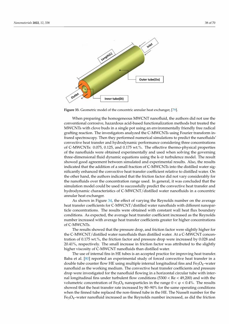
Nanomaterials 2022, 12, 338 38 of 70
Nanomaterials 2022, 12, x FOR PEER REVIEW 37 of 70
The numerical analysis showed a steady improvement when proceeding from Case 2 to 3 to 4. Adding a feedwater heater (FWH) and intercooler to the modified Brayton cycles, especially in Cases 3 and 4, reduces the EFF by 3.7% for Case 3 and 4.9% for Case 4. Similarly, the exergy waste ratio was also lowest in Cases 3 and 4. The reduction in environmental impact was most significant in Case 4, as seen by the high exergy efficiency values. The findings indicate that the intercooler and other modifications such as the feed-water heaters had marginal effect. Cases 3 and 4 were the most sustainable with signifi-cant values of ESI at higher effectiveness.
As shown above, the heat transfer performance of HEs can be improved by using nanofluids as a coolant. Bahiraei et al. [77] reviewed the literature up to 2018 on the use of nanofluids on the heat exchangers and summarized investigations conducted on the use of nanofluids in heat exchangers such as plate, double-pipe, shell-and-tube, and com-pact heat exchangers and produced some fascinating insights into the use of nanofluids in heat exchangers and showed a rapid development in the characteristics of the nanoflu-ids used. Kumar et al. [78] reviewed the application of nanofluids to plate heat exchangers to improve thermal performance by introducing new substances with enhanced proper-ties as working fluids.
Hosseini et al. [79] investigated turbulent heat transfer through a concentric annular heat exchanger, see Figure 33, containing a distilled water-based nanofluid with clove-treated multi-walled carbon nanotubes (C-MWCNTs). The authors tested the thermal and hydrodynamic properties via numerical simulation (finite volume method) for uniform and constant heat flux boundary conditions.
Figure 33. Geometric model of the concentric annular heat exchanger, [79].
When preparing the homogeneous MWCNT nanofluid, the authors did not use the conventional corrosive, hazardous acid-based functionalization methods but treated the MWCNTs with clove buds in a single pot using an environmentally friendly free radical grafting reaction. The investigators analyzed the C-MWCNTs using Fourier transform in-frared spectroscopy. Then they performed numerical simulations to predict the nanoflu-ids’ convective heat transfer and hydrodynamic performance considering three concen-trations of C-MWCNTs: 0.075, 0.125, and 0.175 wt.%. The effective thermo-physical prop-erties of the nanofluids were obtained experimentally and used when solving the govern-ing three-dimensional fluid dynamic equations using the k-ϖ turbulence model. The re-sult showed good agreement between simulated and experimental results. Also, the re-sults indicated that the addition of a small fraction of C-MWCNTs into the distilled water significantly enhanced the convective heat transfer coefficient relative to distilled water. On the other hand, the authors indicated that the friction factor did not vary considerably for the nanofluids over the concentration range used. In general, it was concluded that the simulation model could be used to successfully predict the convective heat transfer and
Figure 33. Geometric model of the concentric annular heat exchanger, [79].
When preparing the homogeneous MWCNT nanofluid, the authors did not use theconventional corrosive, hazardous acid-based functionalization methods but treated theMWCNTs with clove buds in a single pot using an environmentally friendly free radicalgrafting reaction. The investigators analyzed the C-MWCNTs using Fourier transform in-frared spectroscopy. Then they performed numerical simulations to predict the nanofluids’convective heat transfer and hydrodynamic performance considering three concentrationsof C-MWCNTs: 0.075, 0.125, and 0.175 wt.%. The effective thermo-physical propertiesof the nanofluids were obtained experimentally and used when solving the governingthree-dimensional fluid dynamic equations using the k-$ turbulence model. The resultshowed good agreement between simulated and experimental results. Also, the resultsindicated that the addition of a small fraction of C-MWCNTs into the distilled water sig-nificantly enhanced the convective heat transfer coefficient relative to distilled water. Onthe other hand, the authors indicated that the friction factor did not vary considerably forthe nanofluids over the concentration range used. In general, it was concluded that thesimulation model could be used to successfully predict the convective heat transfer andhydrodynamic characteristics of C-MWCNT/distilled water nanofluids in a concentricannular heat exchanger.
As shown in Figure 34, the effect of varying the Reynolds number on the averageheat transfer coefficients for C-MWCNT/distilled water nanofluids with different nanopar-ticle concentrations. The results were obtained with constant wall heat flux boundaryconditions. As expected, the average heat transfer coefficient increased as the Reynoldsnumber increased with average heat transfer coefficients greater for higher concentrationsof C-MWCNTs.
The results showed that the pressure drop, and friction factor were slightly higher forthe C-MWCNT/distilled water nanofluids than distilled water. At a C-MWCNT concen-tration of 0.175 wt.%, the friction factor and pressure drop were increased by 0.028 and20.41%, respectively. The small increase in friction factor was attributed to the slightlyhigher viscosity of C-MWCNT nanofluids than distilled water.
The use of internal fins in HE tubes is an accepted practice for improving heat transfer.Baba et al. [80] reported an experimental study of forced convective heat transfer in adouble tube counter flow HE using multiple internal longitudinal fins and Fe3O4–waternanofluid as the working medium. The convective heat transfer coefficients and pressuredrop were investigated for the nanofluid flowing in a horizontal circular tube with inter-nal longitudinal fins under turbulent flow conditions (5300 < Re < 49,200) and with thevolumetric concentration of Fe3O4 nanoparticles in the range 0 < ϕ < 0.4%. The resultsshowed that the heat transfer rate increased by 80–90% for the same operating conditionswhen the finned tube replaced the non-finned tube in the HE. The Nusselt number for theFe3O4–water nanofluid increased as the Reynolds number increased, as did the friction
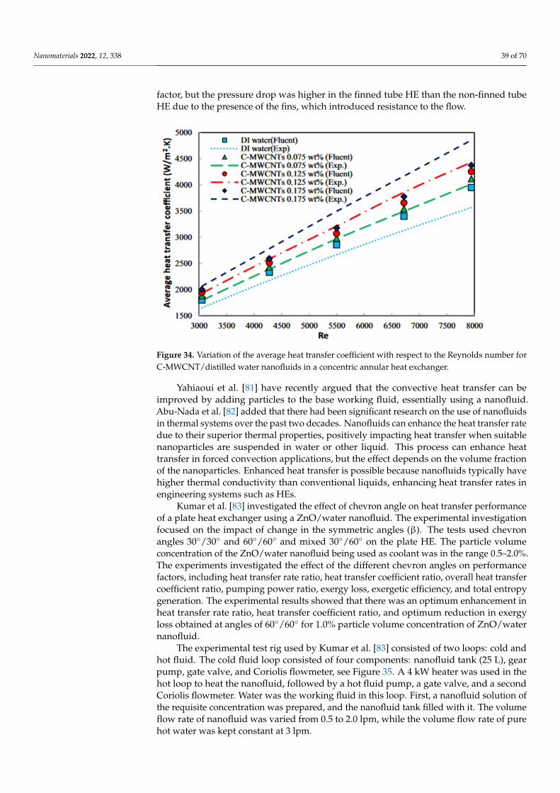
Nanomaterials 2022, 12, 338 39 of 70
factor, but the pressure drop was higher in the finned tube HE than the non-finned tubeHE due to the presence of the fins, which introduced resistance to the flow.
1
Figure 34. Variation of the average heat transfer coefficient with respect to the Reynolds number forC-MWCNT/distilled water nanofluids in a concentric annular heat exchanger.
Yahiaoui et al. [81] have recently argued that the convective heat transfer can beimproved by adding particles to the base working fluid, essentially using a nanofluid.Abu-Nada et al. [82] added that there had been significant research on the use of nanofluidsin thermal systems over the past two decades. Nanofluids can enhance the heat transfer ratedue to their superior thermal properties, positively impacting heat transfer when suitablenanoparticles are suspended in water or other liquid. This process can enhance heattransfer in forced convection applications, but the effect depends on the volume fractionof the nanoparticles. Enhanced heat transfer is possible because nanofluids typically havehigher thermal conductivity than conventional liquids, enhancing heat transfer rates inengineering systems such as HEs.
Kumar et al. [83] investigated the effect of chevron angle on heat transfer performanceof a plate heat exchanger using a ZnO/water nanofluid. The experimental investigationfocused on the impact of change in the symmetric angles (β). The tests used chevronangles 30◦/30◦ and 60◦/60◦ and mixed 30◦/60◦ on the plate HE. The particle volumeconcentration of the ZnO/water nanofluid being used as coolant was in the range 0.5–2.0%.The experiments investigated the effect of the different chevron angles on performancefactors, including heat transfer rate ratio, heat transfer coefficient ratio, overall heat transfercoefficient ratio, pumping power ratio, exergy loss, exergetic efficiency, and total entropygeneration. The experimental results showed that there was an optimum enhancement inheat transfer rate ratio, heat transfer coefficient ratio, and optimum reduction in exergyloss obtained at angles of 60◦/60◦ for 1.0% particle volume concentration of ZnO/waternanofluid.
The experimental test rig used by Kumar et al. [83] consisted of two loops: cold andhot fluid. The cold fluid loop consisted of four components: nanofluid tank (25 L), gearpump, gate valve, and Coriolis flowmeter, see Figure 35. A 4 kW heater was used in thehot loop to heat the nanofluid, followed by a hot fluid pump, a gate valve, and a secondCoriolis flowmeter. Water was the working fluid in this loop. First, a nanofluid solution ofthe requisite concentration was prepared, and the nanofluid tank filled with it. The volumeflow rate of nanofluid was varied from 0.5 to 2.0 lpm, while the volume flow rate of purehot water was kept constant at 3 lpm.
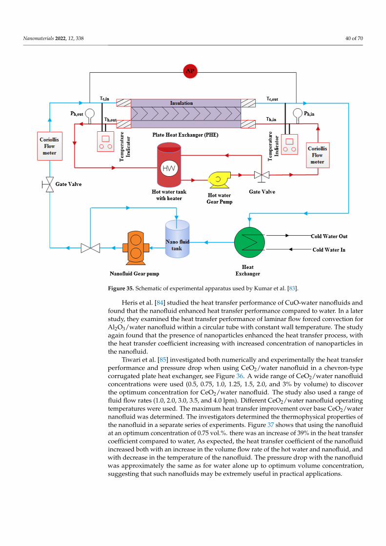
Nanomaterials 2022, 12, 338 40 of 70
Nanomaterials 2022, 12, x FOR PEER REVIEW 39 of 70
nanoparticles. Enhanced heat transfer is possible because nanofluids typically have higher thermal conductivity than conventional liquids, enhancing heat transfer rates in engineer-ing systems such as HEs.
Kumar et al. [83] investigated the effect of chevron angle on heat transfer perfor-mance of a plate heat exchanger using a ZnO/water nanofluid. The experimental investi-gation focused on the impact of change in the symmetric angles (β). The tests used chev-ron angles 30°/30° and 60°/60° and mixed 30°/60° on the plate HE. The particle volume concentration of the ZnO/water nanofluid being used as coolant was in the range 0.5–2.0%. The experiments investigated the effect of the different chevron angles on perfor-mance factors, including heat transfer rate ratio, heat transfer coefficient ratio, overall heat transfer coefficient ratio, pumping power ratio, exergy loss, exergetic efficiency, and total entropy generation. The experimental results showed that there was an optimum en-hancement in heat transfer rate ratio, heat transfer coefficient ratio, and optimum reduc-tion in exergy loss obtained at angles of 60°/60° for 1.0% particle volume concentration of ZnO/water nanofluid.
The experimental test rig used by Kumar et al. [83] consisted of two loops: cold and hot fluid. The cold fluid loop consisted of four components: nanofluid tank (25 L), gear pump, gate valve, and Coriolis flowmeter, see Figure 35. A 4 kW heater was used in the hot loop to heat the nanofluid, followed by a hot fluid pump, a gate valve, and a second Coriolis flowmeter. Water was the working fluid in this loop. First, a nanofluid solution of the requisite concentration was prepared, and the nanofluid tank filled with it. The volume flow rate of nanofluid was varied from 0.5 to 2.0 lpm, while the volume flow rate of pure hot water was kept constant at 3 lpm.
Figure 35. Schematic of experimental apparatus used by Kumar et al. [83].
Heris et al. [84] studied the heat transfer performance of CuO-water nanofluids and found that the nanofluid enhanced heat transfer performance compared to water. In a
Figure 35. Schematic of experimental apparatus used by Kumar et al. [83].
Heris et al. [84] studied the heat transfer performance of CuO-water nanofluids andfound that the nanofluid enhanced heat transfer performance compared to water. In a laterstudy, they examined the heat transfer performance of laminar flow forced convection forAl2O3/water nanofluid within a circular tube with constant wall temperature. The studyagain found that the presence of nanoparticles enhanced the heat transfer process, withthe heat transfer coefficient increasing with increased concentration of nanoparticles inthe nanofluid.
Tiwari et al. [85] investigated both numerically and experimentally the heat transferperformance and pressure drop when using CeO2/water nanofluid in a chevron-typecorrugated plate heat exchanger, see Figure 36. A wide range of CeO2/water nanofluidconcentrations were used (0.5, 0.75, 1.0, 1.25, 1.5, 2.0, and 3% by volume) to discoverthe optimum concentration for CeO2/water nanofluid. The study also used a range offluid flow rates (1.0, 2.0, 3.0, 3.5, and 4.0 lpm). Different CeO2/water nanofluid operatingtemperatures were used. The maximum heat transfer improvement over base CeO2/waternanofluid was determined. The investigators determined the thermophysical properties ofthe nanofluid in a separate series of experiments. Figure 37 shows that using the nanofluidat an optimum concentration of 0.75 vol.%. there was an increase of 39% in the heat transfercoefficient compared to water, As expected, the heat transfer coefficient of the nanofluidincreased both with an increase in the volume flow rate of the hot water and nanofluid, andwith decrease in the temperature of the nanofluid. The pressure drop with the nanofluidwas approximately the same as for water alone up to optimum volume concentration,suggesting that such nanofluids may be extremely useful in practical applications.
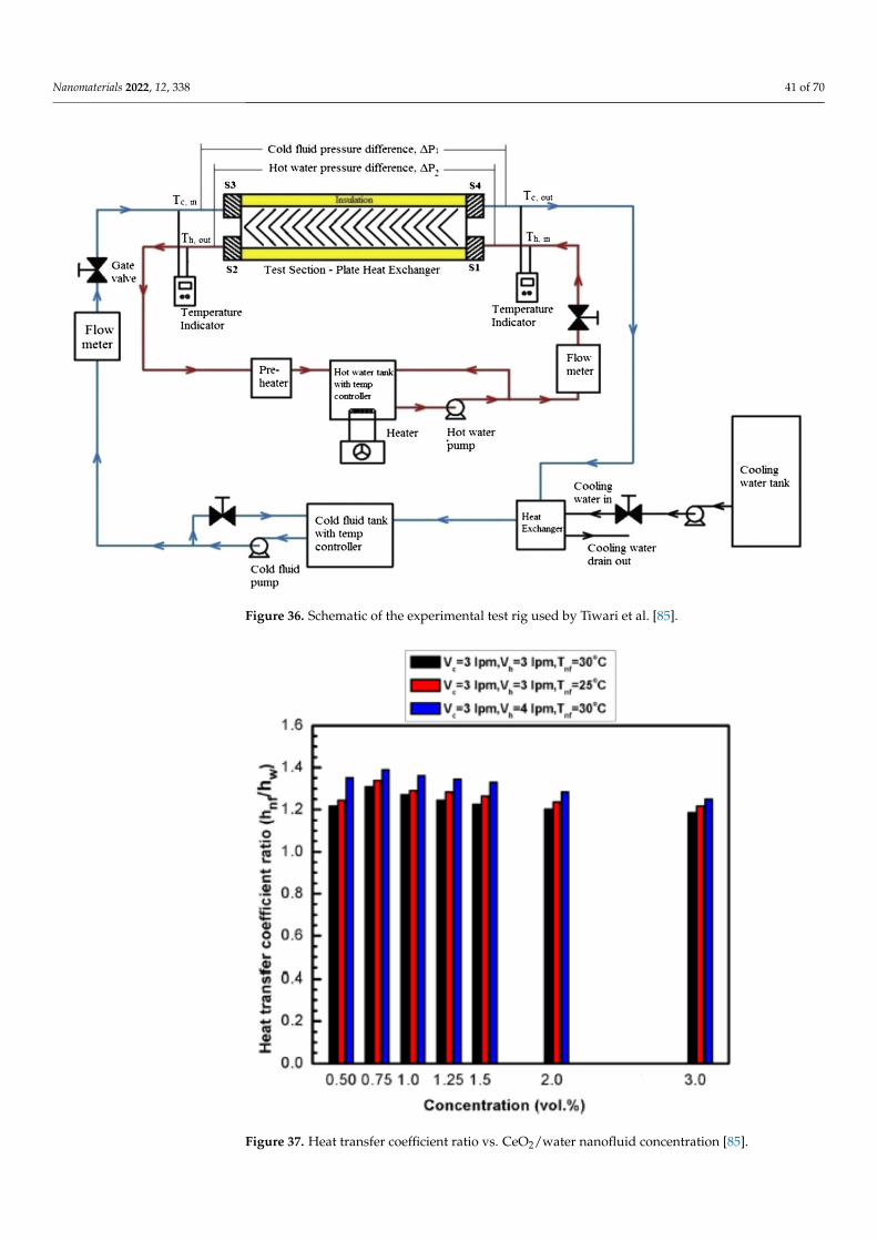
Nanomaterials 2022, 12, 338 41 of 70
Nanomaterials 2022, 12, x FOR PEER REVIEW 40 of 70
later study, they examined the heat transfer performance of laminar flow forced convec-tion for Al2O3/water nanofluid within a circular tube with constant wall temperature. The study again found that the presence of nanoparticles enhanced the heat transfer process, with the heat transfer coefficient increasing with increased concentration of nanoparticles in the nanofluid.
Tiwari et al. [85] investigated both numerically and experimentally the heat transfer performance and pressure drop when using CeO2/water nanofluid in a chevron-type cor-rugated plate heat exchanger, see Figure 36. A wide range of CeO2/water nanofluid con-centrations were used (0.5, 0.75, 1.0, 1.25, 1.5, 2.0, and 3% by volume) to discover the opti-mum concentration for CeO2/water nanofluid. The study also used a range of fluid flow rates (1.0, 2.0, 3.0, 3.5, and 4.0 lpm). Different CeO2/water nanofluid operating tempera-tures were used. The maximum heat transfer improvement over base CeO2/water nanofluid was determined. The investigators determined the thermophysical properties of the nanofluid in a separate series of experiments. Figure 37 shows that using the nanofluid at an optimum concentration of 0.75 vol.%. there was an increase of 39% in the heat transfer coefficient compared to water, As expected, the heat transfer coefficient of the nanofluid increased both with an increase in the volume flow rate of the hot water and nanofluid, and with decrease in the temperature of the nanofluid. The pressure drop with the nanofluid was approximately the same as for water alone up to optimum volume con-centration, suggesting that such nanofluids may be extremely useful in practical applica-tions.
Figure 36. Schematic of the experimental test rig used by Tiwari et al. [85].
Anoop et al. [86] also evaluated nanofluids as the working medium in heat exchang-ers. This study investigated the thermo-physical properties and thermal performance of nanofluids in plate-fin and shell-and-tube HEs. Different volumetric concentrations of 2%, 4%, and 6% of silicon dioxide–water (SiO2–water) with nanoparticles of diameter 20 nm were in a base fluid of pure water. The overall heat transfer coefficient and pressure drop of water vs. nanofluid concentration in laboratory-scale plate-fin and shell-and-tube heat
Figure 36. Schematic of the experimental test rig used by Tiwari et al. [85].
Nanomaterials 2022, 12, x FOR PEER REVIEW 41 of 70
exchangers were assessed experimentally. The test rig used to measure the heat transfer characteristics of the nanofluid is shown in Figure 38. Hot and cold flow loops were set up to operate with counterflow laboratory-scale plate-fin and a shell-and-tube HEs. The plate-fin HE consisted of a corrugated stainless steel plate (70 × 200 mm) embossed with a herringbone pattern. There was a 2 mm gap between each plate. The shell-and-tube HE consisted of 28 single-pass tubes with an inner diameter of 5 mm. The nanofluids flowed through these tubes as the cold medium. Hot water was circulated through the shell side with a diameter of 50 mm. The study also considered fouling on the heat exchangers’ con-tact surfaces.
Figure 37. Heat transfer coefficient ratio vs. CeO2/water nanofluid concentration [85].
Figure 37. Heat transfer coefficient ratio vs. CeO2/water nanofluid concentration [85].
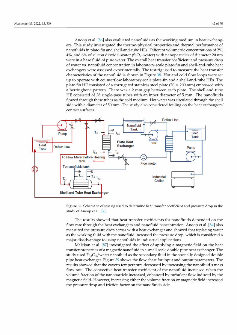
Nanomaterials 2022, 12, 338 42 of 70
Anoop et al. [86] also evaluated nanofluids as the working medium in heat exchang-ers. This study investigated the thermo-physical properties and thermal performance ofnanofluids in plate-fin and shell-and-tube HEs. Different volumetric concentrations of 2%,4%, and 6% of silicon dioxide–water (SiO2–water) with nanoparticles of diameter 20 nmwere in a base fluid of pure water. The overall heat transfer coefficient and pressure dropof water vs. nanofluid concentration in laboratory-scale plate-fin and shell-and-tube heatexchangers were assessed experimentally. The test rig used to measure the heat transfercharacteristics of the nanofluid is shown in Figure 38. Hot and cold flow loops were setup to operate with counterflow laboratory-scale plate-fin and a shell-and-tube HEs. Theplate-fin HE consisted of a corrugated stainless steel plate (70 × 200 mm) embossed witha herringbone pattern. There was a 2 mm gap between each plate. The shell-and-tubeHE consisted of 28 single-pass tubes with an inner diameter of 5 mm. The nanofluidsflowed through these tubes as the cold medium. Hot water was circulated through the shellside with a diameter of 50 mm. The study also considered fouling on the heat exchangers’contact surfaces.
Nanomaterials 2022, 12, x FOR PEER REVIEW 41 of 70
exchangers were assessed experimentally. The test rig used to measure the heat transfer characteristics of the nanofluid is shown in Figure 38. Hot and cold flow loops were set up to operate with counterflow laboratory-scale plate-fin and a shell-and-tube HEs. The plate-fin HE consisted of a corrugated stainless steel plate (70 × 200 mm) embossed with a herringbone pattern. There was a 2 mm gap between each plate. The shell-and-tube HE consisted of 28 single-pass tubes with an inner diameter of 5 mm. The nanofluids flowed through these tubes as the cold medium. Hot water was circulated through the shell side with a diameter of 50 mm. The study also considered fouling on the heat exchangers’ con-tact surfaces.
Figure 37. Heat transfer coefficient ratio vs. CeO2/water nanofluid concentration [85].
Figure 38. Schematic of test rig used to determine heat transfer coefficient and pressure drop in thestudy of Anoop et al. [86].
The results showed that heat transfer coefficients for nanofluids depended on theflow rate through the heat exchangers and nanofluid concentration. Anoop et al. [84] alsomeasured the pressure drop across with a heat exchanger and showed that replacing wateras the working fluid with the nanofluid increased the pressure drop, which is considered amajor disadvantage to using nanofluids in industrial applications.
Malekan et al. [87] investigated the effect of applying a magnetic field on the heattransfer properties of a magnetic nanofluid in a small-scale double pipe heat exchanger. Thestudy used Fe3O4/water nanofluid as the secondary fluid in the specially designed doublepipe heat exchanger. Figure 39 shows the flow chart for input and output parameters. Theresults showed that the cavern temperature decreased by increasing the nanofluid’s massflow rate. The convective heat transfer coefficient of the nanofluid increased when thevolume fraction of the nanoparticle increased, enhanced by turbulent flow induced by themagnetic field. However, increasing either the volume fraction or magnetic field increasedthe pressure drop and friction factor on the nanofluids side.

Nanomaterials 2022, 12, 338 43 of 70
Nanomaterials 2022, 12, x FOR PEER REVIEW 42 of 70
Figure 38. Schematic of test rig used to determine heat transfer coefficient and pressure drop in the study of Anoop et al. [86].
The results showed that heat transfer coefficients for nanofluids depended on the flow rate through the heat exchangers and nanofluid concentration. Anoop et al. [84] also measured the pressure drop across with a heat exchanger and showed that replacing wa-ter as the working fluid with the nanofluid increased the pressure drop, which is consid-ered a major disadvantage to using nanofluids in industrial applications.
Malekan et al. [87] investigated the effect of applying a magnetic field on the heat transfer properties of a magnetic nanofluid in a small-scale double pipe heat exchanger. The study used Fe3O4/water nanofluid as the secondary fluid in the specially designed double pipe heat exchanger. Figure 39 shows the flow chart for input and output param-eters. The results showed that the cavern temperature decreased by increasing the nanofluid’s mass flow rate. The convective heat transfer coefficient of the nanofluid in-creased when the volume fraction of the nanoparticle increased, enhanced by turbulent flow induced by the magnetic field. However, increasing either the volume fraction or magnetic field increased the pressure drop and friction factor on the nanofluids side.
Figure 39. Flowchart with input and output data, [87].
An experimental investigation by Maddah et al. [88] investigated the thermal perfor-mance of a double pipe heat exchanger using Al2O3-TiO2 nanofluids as a working medium and found that using the nanofluids significantly enhanced the performance of the heat exchanger. The heat exchanger was loaded with an Al2O3-TiO2 hybrid nanofluid under turbulent flow conditions. The authors used an exergy approach to study and evaluate the system and experimental data to verify the exergy analysis of the nanofluid-loaded double pipe heat exchanger.
The test variables were: nanofluid concentration in the range of 0.2 to 1.5 vol.%, Reyn-olds number from 3000 to 12,000, and twist ratio between 2 to 8. Statistical analyses of the experimental results confirmed that using the Al2O3-TiO2 hybrid nanofluid rather than conventional water as the heat transfer fluid in the HE improved exergy efficiency. As expected, increasing the nanoparticles volume concentration and the Reynolds number improved the thermal performance of the HE, which also improved the exergy efficiency.
Nakhchi and Esfahani [89] presented a numerical analysis of the heat transfer for Cu-water nanofluid as the working medium flowing through a circular duct, which was fitted internally with cross-cut twisted tape. They applied the k−ϵ turbulence model in three dimensions to simulate the plain tube heat exchanger. Reynolds numbers were in the range 5000 to 15,000 and volume fraction of nanoparticles was from 0 to 1.5 vol.%. The numerical simulation indicated that using nanofluids with higher Re numbers increased the heat transfer rate between the two sides of the HE due to increased convective heat transfer and thermal conductivity. In addition, a higher Re value was better for maintain-ing the homogeneity and stability of the nanofluid. The results showed that the heat trans-fer coefficient increased by up to 23.20% for a nanoparticle volume fraction of 1.5%. Fi-nally, it was shown that the thermal performance increased with increase in the volume fraction of nanoparticles.
Bahiraei et al. [90] investigated the effect of employing a new environmentally friendly biological nanofluid containing functionalized graphene nanoplatelets on the
Figure 39. Flowchart with input and output data, [87].
An experimental investigation by Maddah et al. [88] investigated the thermal perfor-mance of a double pipe heat exchanger using Al2O3-TiO2 nanofluids as a working mediumand found that using the nanofluids significantly enhanced the performance of the heatexchanger. The heat exchanger was loaded with an Al2O3-TiO2 hybrid nanofluid underturbulent flow conditions. The authors used an exergy approach to study and evaluate thesystem and experimental data to verify the exergy analysis of the nanofluid-loaded doublepipe heat exchanger.
The test variables were: nanofluid concentration in the range of 0.2 to 1.5 vol.%,Reynolds number from 3000 to 12,000, and twist ratio between 2 to 8. Statistical analysesof the experimental results confirmed that using the Al2O3-TiO2 hybrid nanofluid ratherthan conventional water as the heat transfer fluid in the HE improved exergy efficiency.As expected, increasing the nanoparticles volume concentration and the Reynolds numberimproved the thermal performance of the HE, which also improved the exergy efficiency.
Nakhchi and Esfahani [89] presented a numerical analysis of the heat transfer forCu-water nanofluid as the working medium flowing through a circular duct, which wasfitted internally with cross-cut twisted tape. They applied the k−ε turbulence model inthree dimensions to simulate the plain tube heat exchanger. Reynolds numbers were inthe range 5000 to 15,000 and volume fraction of nanoparticles was from 0 to 1.5 vol.%. Thenumerical simulation indicated that using nanofluids with higher Re numbers increasedthe heat transfer rate between the two sides of the HE due to increased convective heattransfer and thermal conductivity. In addition, a higher Re value was better for maintainingthe homogeneity and stability of the nanofluid. The results showed that the heat transfercoefficient increased by up to 23.20% for a nanoparticle volume fraction of 1.5%. Finally, itwas shown that the thermal performance increased with increase in the volume fractionof nanoparticles.
Bahiraei et al. [90] investigated the effect of employing a new environmentally friendlybiological nanofluid containing functionalized graphene nanoplatelets on the thermal andhydrodynamic characteristics of a countercurrent spiral heat exchanger. The cold waterflowed on one side of the heat exchanger, while the hot nanofluid or hot base fluid flowedon the other. The results showed that the heat transfer rate, overall heat transfer coefficient,and performance index (ratio of heat transfer rate to pressure drop) increased as eitherReynolds number or nanoplatelet concentration increased. The performance index forthe nanofluid increased over 140% when increasing the Reynolds number from 1000 to3000. On the other hand, while the effectiveness and number of transfer units decreasedwith increasing Reynolds number, the effectiveness of the HE was greater than 0.85 in allcases investigated. Additionally, the nanofluid was doubly efficient at higher values ofReynolds numbers due to a decrease in fouling. However, the pressure drop across theheat exchanger was higher when using the nanofluid due to its greater viscosity. This wasespecially noticeable at high Re values and when the nanofluid was cold.
Ionescu and Neagu [91] numerically studied the effect of using an Al2O3–waternanofluid on the performance of a cross-flow micro heat exchanger. The study numericallymodeled the physical properties of water and the nanofluid, such as density, viscosity,thermal conductivity, and specific heat capacity using Finite Element Method-based ComsolMultiphysics software. The system to be modeled was a cross-flow micro heat exchangermanufactured from 50 stainless steel plates. Each of these plates had 34 rectangularcross-section microchannels of depth 100 µm and width of 200 µm. The nanofluids hadvolumetric concentrations of Al2O3 of 0.5%, 1%, and 1.5%, and its temperature was in
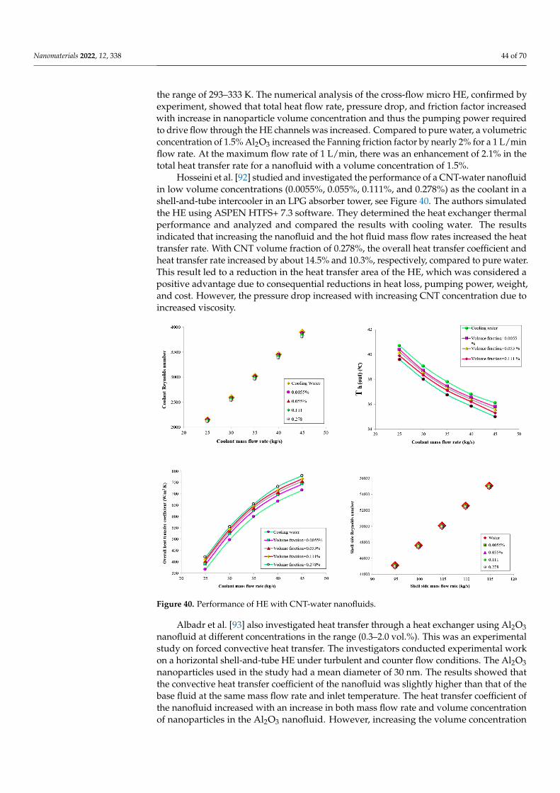
Nanomaterials 2022, 12, 338 44 of 70
the range of 293–333 K. The numerical analysis of the cross-flow micro HE, confirmed byexperiment, showed that total heat flow rate, pressure drop, and friction factor increasedwith increase in nanoparticle volume concentration and thus the pumping power requiredto drive flow through the HE channels was increased. Compared to pure water, a volumetricconcentration of 1.5% Al2O3 increased the Fanning friction factor by nearly 2% for a 1 L/minflow rate. At the maximum flow rate of 1 L/min, there was an enhancement of 2.1% in thetotal heat transfer rate for a nanofluid with a volume concentration of 1.5%.
Hosseini et al. [92] studied and investigated the performance of a CNT-water nanofluidin low volume concentrations (0.0055%, 0.055%, 0.111%, and 0.278%) as the coolant in ashell-and-tube intercooler in an LPG absorber tower, see Figure 40. The authors simulatedthe HE using ASPEN HTFS+ 7.3 software. They determined the heat exchanger thermalperformance and analyzed and compared the results with cooling water. The resultsindicated that increasing the nanofluid and the hot fluid mass flow rates increased the heattransfer rate. With CNT volume fraction of 0.278%, the overall heat transfer coefficient andheat transfer rate increased by about 14.5% and 10.3%, respectively, compared to pure water.This result led to a reduction in the heat transfer area of the HE, which was considered apositive advantage due to consequential reductions in heat loss, pumping power, weight,and cost. However, the pressure drop increased with increasing CNT concentration due toincreased viscosity.
Nanomaterials 2022, 12, x FOR PEER REVIEW 44 of 70
Figure 40. Performance of HE with CNT-water nanofluids.
The main aim of using nanofluids as a working medium in HEs is to reduce energy dependence. Using nanofluids in the industry should have an immediate significant im-pact on current energy usage and the environment and sustainable development.
A nanofluid of aluminum oxide and copper oxide in ethylene glycol base fluid with a volumetric concentration in the range of 2% to 50% was used by Zamzamian et al. [94] to study the effect on forced convective heat transfer coefficient in plate-fin and double pipe counter flow HEs for turbulent flow. The inner diameter of the inner pipe of the double pipe HE was 12 mm and was manufactured from copper with a thickness of 1 mm. The total length of the heat exchanger was 70 cm. The outer shell was prepared from green pipes, with internal diameter of 50.8 mm. The plate heat exchanger was modeled on a common domestic radiator, 40 cm in height, 60 cm in length, with small rectangular fins. The theoretical calculations and measured data showed a significant increase in convec-tive heat transfer coefficient when using nanofluids compared to the base fluid. As the nanoparticles concentration increased, so did the convective heat transfer coefficient.
Rao et al. [95] experimentally investigated the heat transfer rate of nanofluids in a shell-and-tube HE applied to a gas turbine power plant. They considered both single and multi-tubes under turbulent flow conditions with forced convection. In this study, alu-mina nanoparticles were prepared using the Sol-Gel method. Alumina nanoparticles of mean diameter 22 nm were mixed in different volumetric concentrations (0.13%, 0.27%, 0.4%, and 0.53%) with water as a base fluid using an ultra-sonicator. The properties of the nanofluids were calculated. The effects of inlet temperature and mass flow rate of the nanofluid on the heat transfer performance of the HE were investigated. The result showed that the heat transfer rate increased with decreasing particle size in the nanofluid. The authors also demonstrated that the heat transfer rate improved compared to conven-tional fluids.
Recently, the miniaturization of plate HEs and increasing energy efficiency have be-come focal points for research and development. Figure 41 shows the heat transfer rate vs. pressure drop based on different operating conditions of nanofluids from a practical study of plate HEs by Tiwari et al. [96].
Figure 40. Performance of HE with CNT-water nanofluids.
Albadr et al. [93] also investigated heat transfer through a heat exchanger using Al2O3nanofluid at different concentrations in the range (0.3–2.0 vol.%). This was an experimentalstudy on forced convective heat transfer. The investigators conducted experimental workon a horizontal shell-and-tube HE under turbulent and counter flow conditions. The Al2O3nanoparticles used in the study had a mean diameter of 30 nm. The results showed thatthe convective heat transfer coefficient of the nanofluid was slightly higher than that of thebase fluid at the same mass flow rate and inlet temperature. The heat transfer coefficient ofthe nanofluid increased with an increase in both mass flow rate and volume concentrationof nanoparticles in the Al2O3 nanofluid. However, increasing the volume concentration
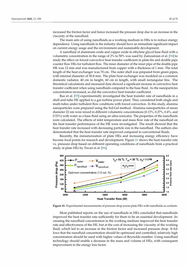
Nanomaterials 2022, 12, 338 45 of 70
increased the friction factor and hence increased the pressure drop due to an increase in theviscosity of the nanofluid.
The main aim of using nanofluids as a working medium in HEs is to reduce energydependence. Using nanofluids in the industry should have an immediate significant impacton current energy usage and the environment and sustainable development.
A nanofluid of aluminum oxide and copper oxide in ethylene glycol base fluid with avolumetric concentration in the range of 2% to 50% was used by Zamzamian et al. [94] tostudy the effect on forced convective heat transfer coefficient in plate-fin and double pipecounter flow HEs for turbulent flow. The inner diameter of the inner pipe of the double pipeHE was 12 mm and was manufactured from copper with a thickness of 1 mm. The totallength of the heat exchanger was 70 cm. The outer shell was prepared from green pipes,with internal diameter of 50.8 mm. The plate heat exchanger was modeled on a commondomestic radiator, 40 cm in height, 60 cm in length, with small rectangular fins. Thetheoretical calculations and measured data showed a significant increase in convective heattransfer coefficient when using nanofluids compared to the base fluid. As the nanoparticlesconcentration increased, so did the convective heat transfer coefficient.
Rao et al. [95] experimentally investigated the heat transfer rate of nanofluids in ashell-and-tube HE applied to a gas turbine power plant. They considered both single andmulti-tubes under turbulent flow conditions with forced convection. In this study, aluminananoparticles were prepared using the Sol-Gel method. Alumina nanoparticles of meandiameter 22 nm were mixed in different volumetric concentrations (0.13%, 0.27%, 0.4%, and0.53%) with water as a base fluid using an ultra-sonicator. The properties of the nanofluidswere calculated. The effects of inlet temperature and mass flow rate of the nanofluid onthe heat transfer performance of the HE were investigated. The result showed that theheat transfer rate increased with decreasing particle size in the nanofluid. The authors alsodemonstrated that the heat transfer rate improved compared to conventional fluids.
Recently, the miniaturization of plate HEs and increasing energy efficiency havebecome focal points for research and development. Figure 41 shows the heat transfer ratevs. pressure drop based on different operating conditions of nanofluids from a practicalstudy of plate HEs by Tiwari et al. [96].
Nanomaterials 2022, 12, x FOR PEER REVIEW 45 of 70
Figure 41. Experimental measurements of pressure drop across plate HEs with nanofluids as cool-ants.
Most published reports on the use of nanofluids in HEs concluded that nanofluids improved the heat transfer rate sufficiently for them to be an essential development. In-creasing the nanofluid concentration in the working medium improved the heat transfer rate and effectiveness of the HE, but at the cost of increasing the viscosity of the working fluid, which led to an increase in the friction factor and increased pressure drop. It follows that the nanofluid concentration should be optimized and controlled, relatively high con-centration should be used with higher values of Reynolds number. Using nanofluid tech-nology should enable a decrease in the mass and volume of HEs, with consequent im-provement in the energy loss factor.
Table 5 summarized the reviewed literature on the effects of nanofluids on heat trans-fer performance of various HEs.
Table 5. A summary of the reviewed literature on the parameters affecting the performance of dif-ferent HEs.
Reference Nanofluid Studied Parameters Remarks Zhao et al.
[73] Al2O3-water
Cu-water Heat transfer performance It was found that the nanofluids improved the heat transfer performance compared to water.
Bahiraei et al. [77]
Different water-based nanofluids
Reviewed the effects of different nanofluids on heat exchanger
performance
It was concluded that using nanofluids increased the heat transfer performance.
Hosseini et al. [79] MWCNT-water
Thermal and hydrodynamic properties
The results indicated that the addition of a small fraction of MWCNTs into distilled water
significantly enhanced the convective heat transfer coefficient.
Baba et al. [90] Fe3O4–water
Forced convective heat transfer and pressure drop in a double tube
counter flow HE
The results showed that the heat transfer rate increased by 80–90% for the same operating
conditions when the finned tube HE replaced the non-finned tube HE.
Kumar et al. [83]
ZnO/water The effect of chevron angle on heat transfer performance of a plate heat
exchanger using a nanofluid
It was reported that there was an optimum enhancement in heat transfer rate ratio, heat
transfer coefficient ratio, and optimum reduction in exergy loss obtained at angles of 60°/60° for 1.0%
particle volume concentration of ZnO/water nanofluid.
Heris et al. [84]
CuO-water Al2O3/water Heat transfer performance The study found that the presence of nanoparticles
enhanced the heat transfer process, with the heat
Figure 41. Experimental measurements of pressure drop across plate HEs with nanofluids as coolants.
Most published reports on the use of nanofluids in HEs concluded that nanofluidsimproved the heat transfer rate sufficiently for them to be an essential development. In-creasing the nanofluid concentration in the working medium improved the heat transferrate and effectiveness of the HE, but at the cost of increasing the viscosity of the workingfluid, which led to an increase in the friction factor and increased pressure drop. It fol-lows that the nanofluid concentration should be optimized and controlled, relatively highconcentration should be used with higher values of Reynolds number. Using nanofluidtechnology should enable a decrease in the mass and volume of HEs, with consequentimprovement in the energy loss factor.
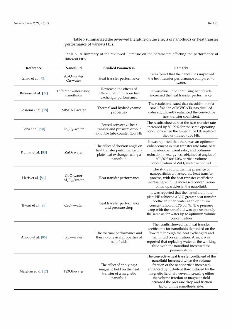
Nanomaterials 2022, 12, 338 46 of 70
Table 5 summarized the reviewed literature on the effects of nanofluids on heat transferperformance of various HEs.
Table 5. A summary of the reviewed literature on the parameters affecting the performance ofdifferent HEs.
Reference Nanofluid Studied Parameters Remarks
Zhao et al. [73] Al2O3-waterCu-water Heat transfer performance
It was found that the nanofluids improvedthe heat transfer performance compared to
water.
Bahiraei et al. [77] Different water-basednanofluids
Reviewed the effects ofdifferent nanofluids on heat
exchanger performance
It was concluded that using nanofluidsincreased the heat transfer performance.
Hosseini et al. [79] MWCNT-water Thermal and hydrodynamicproperties
The results indicated that the addition of asmall fraction of MWCNTs into distilled
water significantly enhanced the convectiveheat transfer coefficient.
Baba et al. [90] Fe3O4–waterForced convective heat
transfer and pressure drop ina double tube counter flow HE
The results showed that the heat transfer rateincreased by 80–90% for the same operatingconditions when the finned tube HE replaced
the non-finned tube HE.
Kumar et al. [83] ZnO/water
The effect of chevron angle onheat transfer performance of aplate heat exchanger using a
nanofluid
It was reported that there was an optimumenhancement in heat transfer rate ratio, heat
transfer coefficient ratio, and optimumreduction in exergy loss obtained at angles of
60◦/60◦ for 1.0% particle volumeconcentration of ZnO/water nanofluid.
Heris et al. [84] CuO-waterAl2O3/water Heat transfer performance
The study found that the presence ofnanoparticles enhanced the heat transferprocess, with the heat transfer coefficient
increasing with the increased concentrationof nanoparticles in the nanofluid.
Tiwari et al. [85] CeO2-water Heat transfer performanceand pressure drop
It was reported that the nanofluid in theplate HE achieved a 39% greater heat transfer
coefficient than water at an optimumconcentration of 0.75 vol.%. The pressure
drop with the nanofluid was approximatelythe same as for water up to optimum volume
concentration
Anoop et al. [86] SiO2–waterThe thermal performance andthermo-physical properties of
nanofluids
The results showed that heat transfercoefficients for nanofluids depended on theflow rate through the heat exchangers and
nanofluid concentration. Also, it wasreported that replacing water as the working
fluid with the nanofluid increased thepressure drop.
Malekan et al. [87] Fe3O4-water
The effect of applying amagnetic field on the heat
transfer of a magneticnanofluid
The convective heat transfer coefficient of thenanofluid increased when the volumefraction of the nanoparticle increased,
enhanced by turbulent flow induced by themagnetic field. However, increasing either
the volume fraction or magnetic fieldincreased the pressure drop and friction
factor on the nanofluids side.
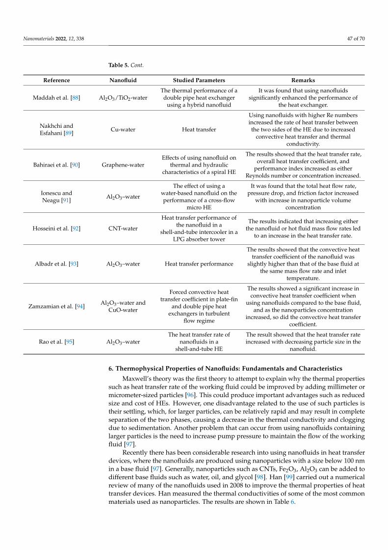
Nanomaterials 2022, 12, 338 47 of 70
Table 5. Cont.
Reference Nanofluid Studied Parameters Remarks
Maddah et al. [88] Al2O3/TiO2-waterThe thermal performance of adouble pipe heat exchanger
using a hybrid nanofluid
It was found that using nanofluidssignificantly enhanced the performance of
the heat exchanger.
Nakhchi andEsfahani [89] Cu-water Heat transfer
Using nanofluids with higher Re numbersincreased the rate of heat transfer betweenthe two sides of the HE due to increased
convective heat transfer and thermalconductivity.
Bahiraei et al. [90] Graphene-waterEffects of using nanofluid on
thermal and hydrauliccharacteristics of a spiral HE
The results showed that the heat transfer rate,overall heat transfer coefficient, and
performance index increased as eitherReynolds number or concentration increased.
Ionescu andNeagu [91] Al2O3–water
The effect of using awater-based nanofluid on theperformance of a cross-flow
micro HE
It was found that the total heat flow rate,pressure drop, and friction factor increased
with increase in nanoparticle volumeconcentration
Hosseini et al. [92] CNT-water
Heat transfer performance ofthe nanofluid in a
shell-and-tube intercooler in aLPG absorber tower
The results indicated that increasing eitherthe nanofluid or hot fluid mass flow rates led
to an increase in the heat transfer rate.
Albadr et al. [93] Al2O3–water Heat transfer performance
The results showed that the convective heattransfer coefficient of the nanofluid was
slightly higher than that of the base fluid atthe same mass flow rate and inlet
temperature.
Zamzamian et al. [94] Al2O3–water andCuO-water
Forced convective heattransfer coefficient in plate-fin
and double pipe heatexchangers in turbulent
flow regime
The results showed a significant increase inconvective heat transfer coefficient when
using nanofluids compared to the base fluid,and as the nanoparticles concentration
increased, so did the convective heat transfercoefficient.
Rao et al. [95] Al2O3–waterThe heat transfer rate of
nanofluids in ashell-and-tube HE
The result showed that the heat transfer rateincreased with decreasing particle size in the
nanofluid.
6. Thermophysical Properties of Nanofluids: Fundamentals and Characteristics
Maxwell’s theory was the first theory to attempt to explain why the thermal propertiessuch as heat transfer rate of the working fluid could be improved by adding millimeter ormicrometer-sized particles [96]. This could produce important advantages such as reducedsize and cost of HEs. However, one disadvantage related to the use of such particles istheir settling, which, for larger particles, can be relatively rapid and may result in completeseparation of the two phases, causing a decrease in the thermal conductivity and cloggingdue to sedimentation. Another problem that can occur from using nanofluids containinglarger particles is the need to increase pump pressure to maintain the flow of the workingfluid [97].
Recently there has been considerable research into using nanofluids in heat transferdevices, where the nanofluids are produced using nanoparticles with a size below 100 nmin a base fluid [97]. Generally, nanoparticles such as CNTs, Fe2O3, Al2O3 can be added todifferent base fluids such as water, oil, and glycol [98]. Han [99] carried out a numericalreview of many of the nanofluids used in 2008 to improve the thermal properties of heattransfer devices. Han measured the thermal conductivities of some of the most commonmaterials used as nanoparticles. The results are shown in Table 6.
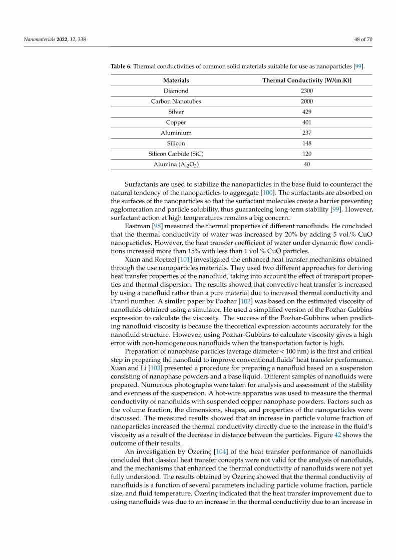
Nanomaterials 2022, 12, 338 48 of 70
Table 6. Thermal conductivities of common solid materials suitable for use as nanoparticles [99].
Materials Thermal Conductivity [W/(m.K)]
Diamond 2300
Carbon Nanotubes 2000
Silver 429
Copper 401
Aluminium 237
Silicon 148
Silicon Carbide (SiC) 120
Alumina (Al2O3) 40
Surfactants are used to stabilize the nanoparticles in the base fluid to counteract thenatural tendency of the nanoparticles to aggregate [100]. The surfactants are absorbed onthe surfaces of the nanoparticles so that the surfactant molecules create a barrier preventingagglomeration and particle solubility, thus guaranteeing long-term stability [99]. However,surfactant action at high temperatures remains a big concern.
Eastman [98] measured the thermal properties of different nanofluids. He concludedthat the thermal conductivity of water was increased by 20% by adding 5 vol.% CuOnanoparticles. However, the heat transfer coefficient of water under dynamic flow condi-tions increased more than 15% with less than 1 vol.% CuO particles.
Xuan and Roetzel [101] investigated the enhanced heat transfer mechanisms obtainedthrough the use nanoparticles materials. They used two different approaches for derivingheat transfer properties of the nanofluid, taking into account the effect of transport proper-ties and thermal dispersion. The results showed that convective heat transfer is increasedby using a nanofluid rather than a pure material due to increased thermal conductivity andPrantl number. A similar paper by Pozhar [102] was based on the estimated viscosity ofnanofluids obtained using a simulator. He used a simplified version of the Pozhar-Gubbinsexpression to calculate the viscosity. The success of the Pozhar-Gubbins when predict-ing nanofluid viscosity is because the theoretical expression accounts accurately for thenanofluid structure. However, using Pozhar-Gubbins to calculate viscosity gives a higherror with non-homogeneous nanofluids when the transportation factor is high.
Preparation of nanophase particles (average diameter < 100 nm) is the first and criticalstep in preparing the nanofluid to improve conventional fluids’ heat transfer performance.Xuan and Li [103] presented a procedure for preparing a nanofluid based on a suspensionconsisting of nanophase powders and a base liquid. Different samples of nanofluids wereprepared. Numerous photographs were taken for analysis and assessment of the stabilityand evenness of the suspension. A hot-wire apparatus was used to measure the thermalconductivity of nanofluids with suspended copper nanophase powders. Factors such asthe volume fraction, the dimensions, shapes, and properties of the nanoparticles werediscussed. The measured results showed that an increase in particle volume fraction ofnanoparticles increased the thermal conductivity directly due to the increase in the fluid’sviscosity as a result of the decrease in distance between the particles. Figure 42 shows theoutcome of their results.
An investigation by Özerinç [104] of the heat transfer performance of nanofluidsconcluded that classical heat transfer concepts were not valid for the analysis of nanofluids,and the mechanisms that enhanced the thermal conductivity of nanofluids were not yetfully understood. The results obtained by Özerinç showed that the thermal conductivity ofnanofluids is a function of several parameters including particle volume fraction, particlesize, and fluid temperature. Özerinç indicated that the heat transfer improvement due tousing nanofluids was due to an increase in the thermal conductivity due to an increase in
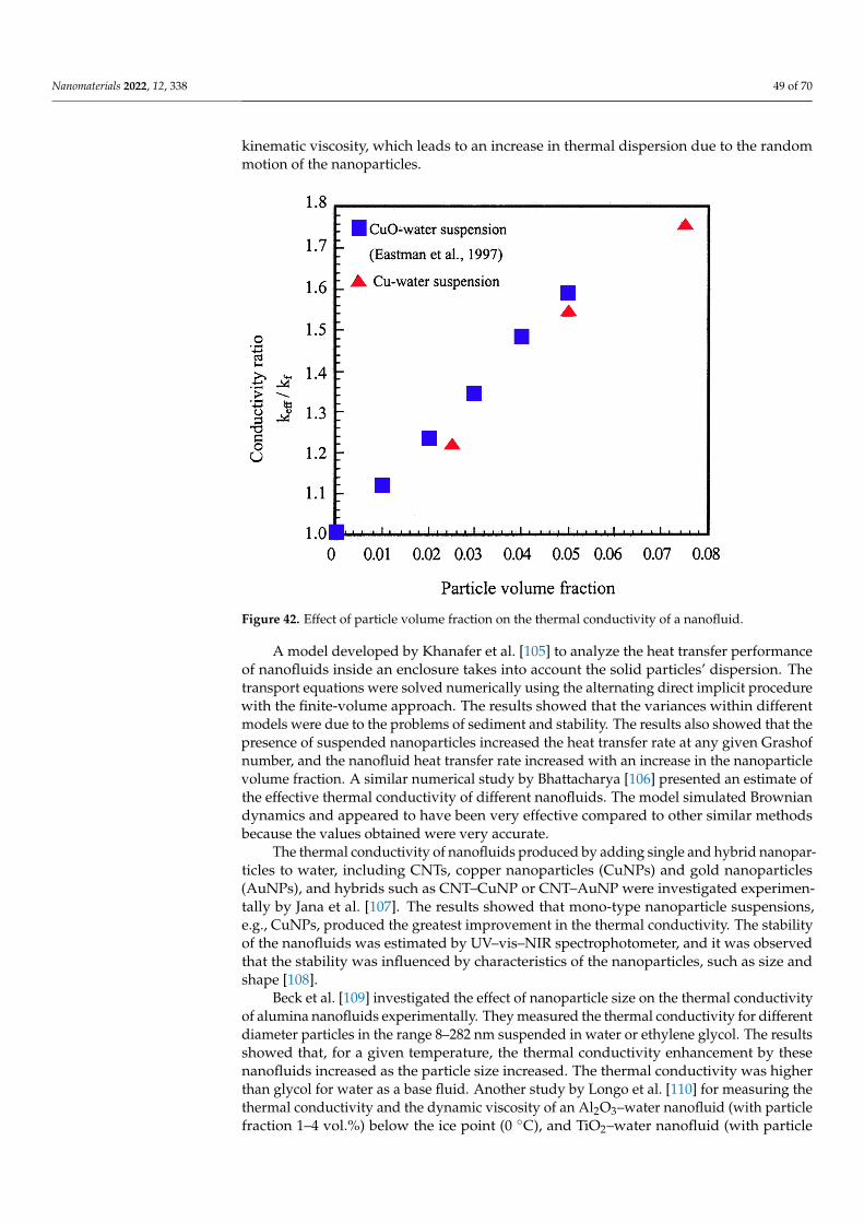
Nanomaterials 2022, 12, 338 49 of 70
kinematic viscosity, which leads to an increase in thermal dispersion due to the randommotion of the nanoparticles.
Nanomaterials 2022, 12, x FOR PEER REVIEW 48 of 70
performance. Xuan and Li [103] presented a procedure for preparing a nanofluid based on a suspension consisting of nanophase powders and a base liquid. Different samples of nanofluids were prepared. Numerous photographs were taken for analysis and assess-ment of the stability and evenness of the suspension. A hot-wire apparatus was used to measure the thermal conductivity of nanofluids with suspended copper nanophase pow-ders. Factors such as the volume fraction, the dimensions, shapes, and properties of the nanoparticles were discussed. The measured results showed that an increase in particle volume fraction of nanoparticles increased the thermal conductivity directly due to the increase in the fluid’s viscosity as a result of the decrease in distance between the particles. Figure 42 shows the outcome of their results.
Figure 42. Effect of particle volume fraction on the thermal conductivity of a nanofluid.
An investigation by Özerinç [104] of the heat transfer performance of nanofluids con-cluded that classical heat transfer concepts were not valid for the analysis of nanofluids, and the mechanisms that enhanced the thermal conductivity of nanofluids were not yet fully understood. The results obtained by Özerinç showed that the thermal conductivity of nanofluids is a function of several parameters including particle volume fraction, par-ticle size, and fluid temperature. Özerinç indicated that the heat transfer improvement due to using nanofluids was due to an increase in the thermal conductivity due to an increase in kinematic viscosity, which leads to an increase in thermal dispersion due to the random motion of the nanoparticles.
A model developed by Khanafer et al. [105] to analyze the heat transfer performance of nanofluids inside an enclosure takes into account the solid particles’ dispersion. The transport equations were solved numerically using the alternating direct implicit proce-dure with the finite-volume approach. The results showed that the variances within dif-ferent models were due to the problems of sediment and stability. The results also showed that the presence of suspended nanoparticles increased the heat transfer rate at any given Grashof number, and the nanofluid heat transfer rate increased with an increase in the nanoparticle volume fraction. A similar numerical study by Bhattacharya [106] presented an estimate of the effective thermal conductivity of different nanofluids. The model
Figure 42. Effect of particle volume fraction on the thermal conductivity of a nanofluid.
A model developed by Khanafer et al. [105] to analyze the heat transfer performanceof nanofluids inside an enclosure takes into account the solid particles’ dispersion. Thetransport equations were solved numerically using the alternating direct implicit procedurewith the finite-volume approach. The results showed that the variances within differentmodels were due to the problems of sediment and stability. The results also showed that thepresence of suspended nanoparticles increased the heat transfer rate at any given Grashofnumber, and the nanofluid heat transfer rate increased with an increase in the nanoparticlevolume fraction. A similar numerical study by Bhattacharya [106] presented an estimate ofthe effective thermal conductivity of different nanofluids. The model simulated Browniandynamics and appeared to have been very effective compared to other similar methodsbecause the values obtained were very accurate.
The thermal conductivity of nanofluids produced by adding single and hybrid nanopar-ticles to water, including CNTs, copper nanoparticles (CuNPs) and gold nanoparticles(AuNPs), and hybrids such as CNT–CuNP or CNT–AuNP were investigated experimen-tally by Jana et al. [107]. The results showed that mono-type nanoparticle suspensions,e.g., CuNPs, produced the greatest improvement in the thermal conductivity. The stabilityof the nanofluids was estimated by UV–vis–NIR spectrophotometer, and it was observedthat the stability was influenced by characteristics of the nanoparticles, such as size andshape [108].
Beck et al. [109] investigated the effect of nanoparticle size on the thermal conductivityof alumina nanofluids experimentally. They measured the thermal conductivity for differentdiameter particles in the range 8–282 nm suspended in water or ethylene glycol. The resultsshowed that, for a given temperature, the thermal conductivity enhancement by thesenanofluids increased as the particle size increased. The thermal conductivity was higherthan glycol for water as a base fluid. Another study by Longo et al. [110] for measuring thethermal conductivity and the dynamic viscosity of an Al2O3–water nanofluid (with particlefraction 1–4 vol.%) below the ice point (0 ◦C), and TiO2–water nanofluid (with particle
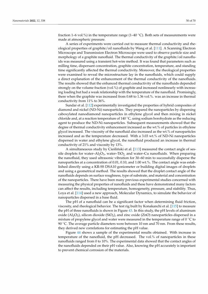
Nanomaterials 2022, 12, 338 50 of 70
fraction 1–6 vol.%) in the temperature range (1–40 ◦C). Both sets of measurements weremade at atmospheric pressure.
A series of experiments were carried out to measure thermal conductivity and rhe-ological properties of graphite/oil nanofluids by Wang et al. [111]. A Scanning ElectronMicroscope and Transmission Electron Microscope were used to observe particle size andmorphology of a graphite nanofluid. The thermal conductivity of the graphite/oil nanoflu-ids was measured using a transient hot-wire method. It was found that parameters such asmilling time, dispersant concentration, graphite concentration, temperature, and standingtime significantly affected the thermal conductivity. Moreover, the rheological propertieswere examined to reveal the microstructure lay in the nanofluids, which could supplya direct explanation of the enhancement of the thermal conductivity of the nanofluids.The results showed that the enhanced thermal conductivity of the nanofluids dependedstrongly on the volume fraction (vol.%) of graphite and increased nonlinearly with increas-ing loading but had a weak relationship with the temperature of the nanofluid. Promisingly,there when the graphite was increased from 0.68 to 1.36 vol.%. was an increase in thermalconductivity from 11% to 36%.
Sundar et al. [112] experimentally investigated the properties of hybrid composites ofdiamond and nickel (ND-Ni) nanoparticles. They prepared the nanoparticles by dispersingcaboxylated nanodiamond nanoparticles in ethylene glycol and then mixing in nickelchloride and, at a reaction temperature of 140 ◦C, using sodium borohydrate as the reducingagent to produce the ND-Ni nanoparticles. Subsequent measurements showed that thedegree of thermal conductivity enhancement increased as the wt.% of particles in ethyleneglycol increased. The viscosity of the nanofluid also increased as the wt.% of nanoparticlesincreased and as the temperature decreased. With a 3.03 wt.% of ND-Ni nanoparticlesdispersed in water and ethylene glycol, the nanofluid produced an increase in thermalconductivity of 21% and viscosity by 13%.
A simultaneaous study by Cieslinski et al. [113] measured the contact angle of ses-sile droplets for water–Al2O3, water–TiO2, and water–Cu nanofluids. When preparingthe nanofluid, they used ultrasonic vibration for 30–60 min to successfully disperse thenanoparticles at a concentration of 0.01, 0.10, and 1.00 wt.%. The contact angle was estab-lished directly using a KR-SS DSA10 goniometer or building digital images of dropletsand using a geometrical method. The results showed that the droplet contact angle of thenanofluids depends on surface roughness, type of substrate, and material and concentrationof the nanoparticles. There have been many previous experimental studies concerned withmeasuring the physical properties of nanofluids and these have demonstrated many factorscan affect the results, including temperature, homogeneity, pressure, and stability. Thus,Loya et al. [114] used a new approach, Molecular Dynamics, to simulate the behavior ofnanoparticles dispersed in a base fluid.
The pH of a nanofluid can be a significant factor when determining fluid friction,viscosity, and rheological behavior. The test rig built by Konakanchi et al. [115] to measurethe pH of three nanofluids is shown in Figure 43. In this study, the pH levels of aluminumoxide (Al2O3), silicon dioxide (SiO2), and zinc oxide (ZnO) nanoparticles dispersed in amixture of propylene glycol and water were measured in the temperature range of 0 ◦C to90 ◦C. The average particle diameters were between 10 nm and 70 nm. From these results,they derived new correlations for estimating the pH value.
Figure 44 shows a sample of the experimental results obtained. With increase intemperature of the nanofluid, the pH decreased. The vol.% of nanoparticles in thesenanofluids ranged from 0 to 10%. The experimental data showed that the contact angles ofthe nanofluids depended on their pH value. Also, knowing the pH accurately is importantto prevent chemical corrosion of the materials.
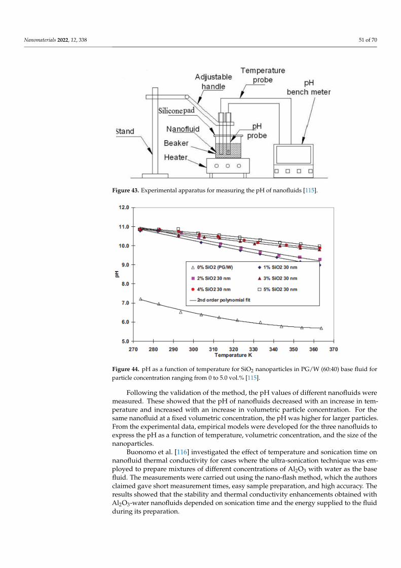
Nanomaterials 2022, 12, 338 51 of 70
Nanomaterials 2022, 12, x FOR PEER REVIEW 50 of 70
Thus, Loya et al. [114] used a new approach, Molecular Dynamics, to simulate the behav-ior of nanoparticles dispersed in a base fluid.
The pH of a nanofluid can be a significant factor when determining fluid friction, viscosity, and rheological behavior. The test rig built by Konakanchi et al. [115] to measure the pH of three nanofluids is shown in Figure 43. In this study, the pH levels of aluminum oxide (Al2O3), silicon dioxide (SiO2), and zinc oxide (ZnO) nanoparticles dispersed in a mixture of propylene glycol and water were measured in the temperature range of 0 °C to 90 °C. The average particle diameters were between 10 nm and 70 nm. From these re-sults, they derived new correlations for estimating the pH value.
Figure 43. Experimental apparatus for measuring the pH of nanofluids [115].
Figure 44 shows a sample of the experimental results obtained. With increase in tem-perature of the nanofluid, the pH decreased. The vol.% of nanoparticles in these nanoflu-ids ranged from 0 to 10%. The experimental data showed that the contact angles of the nanofluids depended on their pH value. Also, knowing the pH accurately is important to prevent chemical corrosion of the materials.
Figure 44. pH as a function of temperature for SiO2 nanoparticles in PG/W (60:40) base fluid for particle concentration ranging from 0 to 5.0 vol.% [115].
Figure 43. Experimental apparatus for measuring the pH of nanofluids [115].
Nanomaterials 2022, 12, x FOR PEER REVIEW 50 of 70
Thus, Loya et al. [114] used a new approach, Molecular Dynamics, to simulate the behav-ior of nanoparticles dispersed in a base fluid.
The pH of a nanofluid can be a significant factor when determining fluid friction, viscosity, and rheological behavior. The test rig built by Konakanchi et al. [115] to measure the pH of three nanofluids is shown in Figure 43. In this study, the pH levels of aluminum oxide (Al2O3), silicon dioxide (SiO2), and zinc oxide (ZnO) nanoparticles dispersed in a mixture of propylene glycol and water were measured in the temperature range of 0 °C to 90 °C. The average particle diameters were between 10 nm and 70 nm. From these re-sults, they derived new correlations for estimating the pH value.
Figure 43. Experimental apparatus for measuring the pH of nanofluids [115].
Figure 44 shows a sample of the experimental results obtained. With increase in tem-perature of the nanofluid, the pH decreased. The vol.% of nanoparticles in these nanoflu-ids ranged from 0 to 10%. The experimental data showed that the contact angles of the nanofluids depended on their pH value. Also, knowing the pH accurately is important to prevent chemical corrosion of the materials.
Figure 44. pH as a function of temperature for SiO2 nanoparticles in PG/W (60:40) base fluid for particle concentration ranging from 0 to 5.0 vol.% [115].
Figure 44. pH as a function of temperature for SiO2 nanoparticles in PG/W (60:40) base fluid forparticle concentration ranging from 0 to 5.0 vol.% [115].
Following the validation of the method, the pH values of different nanofluids weremeasured. These showed that the pH of nanofluids decreased with an increase in tem-perature and increased with an increase in volumetric particle concentration. For thesame nanofluid at a fixed volumetric concentration, the pH was higher for larger particles.From the experimental data, empirical models were developed for the three nanofluids toexpress the pH as a function of temperature, volumetric concentration, and the size of thenanoparticles.
Buonomo et al. [116] investigated the effect of temperature and sonication time onnanofluid thermal conductivity for cases where the ultra-sonication technique was em-ployed to prepare mixtures of different concentrations of Al2O3 with water as the basefluid. The measurements were carried out using the nano-flash method, which the authorsclaimed gave short measurement times, easy sample preparation, and high accuracy. Theresults showed that the stability and thermal conductivity enhancements obtained withAl2O3-water nanofluids depended on sonication time and the energy supplied to the fluidduring its preparation.

Nanomaterials 2022, 12, 338 52 of 70
Parametthanuwat et al. [117] experimentally investigated the thermal properties andbehavior of 0.5 wt.% silver in a silver nanofluid. The nanoparticle-based nanofluids con-tained oleic acid and potassium oleate surfactant (OAK+) with concentrations of 0.5, 1.0,and 1.5 wt.%. The experiments were conducted at temperatures from 20◦C to 80 ◦C. It wasshown that the thermal properties of a nanofluid with 1.0 wt.% OAK+ were improved byabout 28% at 80 ◦C compared to deionized water. In general, the results showed that thethermal performance when using nanofluid was improved over that of the base fluid by 80%approximately. The rheological data showed that the viscosity of the nanofluid dependedsignificantly on temperature. As the shear rate increased, the shear stress of the nanofluidincreased; however, the viscosity of the nanofluids first decreased and then stabilized.
The heat transfer behavior of TiO2-water nanofluids with volume concentrations of0.10, 0.25, 0.50, and 0.75 vol.% was investigated by Arulprakasajothi et al. [118]. Thenanofluids were prepared using the two-step method through a tube heat exchanger. Sta-bility, thermal conductivity, and viscosity were measured. Figure 45 presents the resultsobtained, showing the effect of volume concentration on thermal conductivity and viscos-ity. As expected, an increase in the concentration of nanoparticles increased the thermalconductivity and the convective heat transfer coefficient due to an increase in the Nusseltnumber. The experimental results showed that the Nusselt number increased with increaseof particle volume fraction. The Nusselt number enhancement reached 13.2% over the basefluid for 0.75 wt.%. Figure 45 also shows the obtained relation between shear stress andviscosity. As nanoparticle concentration increased, the viscosity increased, indicating thatthe shear force increased.
Nanomaterials 2022, 12, x FOR PEER REVIEW 52 of 70
Figure 45. Thermal conductivity of TiO2/water nanofluid as a function of vol.% of nanoparticles, and viscosity as a function of shear rate% [118].
A new model for simulating the effective thermal conductivity of aluminum oxide (Al2O3) and titanium dioxide (TiO2) suspended in water and ethylene glycol was devel-oped by Shukla et al. [120]. The authors introduced convective heat transfer due to the Brownian motion of spherical and non-spherical particles. It was concluded that the effec-tive thermal conductivity of nanofluids is a function of volume fraction, nanoparticle di-ameter and shape, and temperature. The theoretical results suggested that a more pro-nounced increase in the effective thermal conductivity could be achieved using non-spherical nanoparticles having a larger volume-specific surface area.
Eshghinejadfard and Thévenin [121] numerically investigated heat transfer in partic-ulate flow around an obstacle. They applied the Lattice Boltzmann Method (LBM) to an-alyze the heat transfer when a nanofluid flowed around an immersed sphere, using two and three-dimensional configurations in their simulation. They estimated the hydrody-namic force and energy exchange between the particle and the fluid through the direct heating immersed boundary (IB) method. The simulated results produced by this thermal IB-LBM accurately predicted the particle motion of nanofluids.
Bouguerra et al. [122] revisiting the influences of pH values and surfactant concen-trations on the thermal conductivity of Al2O3-water nanofluids. The effect of production factors on the measured pH and stability of the Al2O3-water nanofluids was investigated. The results showed that the thermal conductivity is controlled mainly by the pH of the mixture, and maximum thermal conductivity can be achieved without adding surfactants.
Figure 45. Thermal conductivity of TiO2/water nanofluid as a function of vol.% of nanoparticles,and viscosity as a function of shear rate% [118].

Nanomaterials 2022, 12, 338 53 of 70
Yerrennagoudaru et al. [119] carried out a series of CFD simulations and experimentsthat showed the thermal properties, especially thermal conductivity, of heat transfer medi-ums, were improved by using nanoparticles with diameters in the range of 70 to 230 nm.They investigated the use of water-based nanofluids that used magnesium oxide, copperoxide, titanium oxide, and iron oxide nanoparticles in a simple double pipe heat exchanger.These investigators used the two-step method for preparing the different nanofluids as thiswas, and is, the most commonly used for preparing nanofluids. This method is very properand economical for producing nanofluids using the nanopowder technique for industrialproduction levels. The procedure for this method can be summarized as: obtaining thenanoparticles, nanofibers, nanotubes, or other nanomaterial as a dry powder produced bychemical or physical methods. Then the nanosized powder is suspended in a base fluid.
A new model for simulating the effective thermal conductivity of aluminum oxide(Al2O3) and titanium dioxide (TiO2) suspended in water and ethylene glycol was developedby Shukla et al. [120]. The authors introduced convective heat transfer due to the Brownianmotion of spherical and non-spherical particles. It was concluded that the effective thermalconductivity of nanofluids is a function of volume fraction, nanoparticle diameter andshape, and temperature. The theoretical results suggested that a more pronounced increasein the effective thermal conductivity could be achieved using non-spherical nanoparticleshaving a larger volume-specific surface area.
Eshghinejadfard and Thévenin [121] numerically investigated heat transfer in particu-late flow around an obstacle. They applied the Lattice Boltzmann Method (LBM) to analyzethe heat transfer when a nanofluid flowed around an immersed sphere, using two andthree-dimensional configurations in their simulation. They estimated the hydrodynamicforce and energy exchange between the particle and the fluid through the direct heatingimmersed boundary (IB) method. The simulated results produced by this thermal IB-LBMaccurately predicted the particle motion of nanofluids.
Bouguerra et al. [122] revisiting the influences of pH values and surfactant concen-trations on the thermal conductivity of Al2O3-water nanofluids. The effect of productionfactors on the measured pH and stability of the Al2O3-water nanofluids was investigated.The results showed that the thermal conductivity is controlled mainly by the pH of themixture, and maximum thermal conductivity can be achieved without adding surfactants.However, the nanofluid properties are best optimized by a combination of pH value, sur-factant, particle size, and particle concentration, with the surfactant limited to less thanabout 0.03 wt.%.
The effect of temperature and particle concentration on the pH of different nanocolloids was investigated experimentally by Katiyar et al. [123]. Measurements showedthat the pH of nano colloids is a strong function of temperature and the concentration of thedispersed phase, as shown in Figure 46. Charge transport mechanisms leading to changesin the effective proton population indicated that the stability of nanofluids is based on theconcentration rate used and working temperature.
Tertsinidou et al. [124] presented a new technique for measuring the thermal con-ductivity of nanofluids and experimentally investigated how adding nanoparticles ornanotubes to a fluid improved the heat transfer performance and affected the viscosity.The nanofluids were CuO, TiO2, or Al2O3 nanoparticles in ethylene glycol, or TiO2, Al2O3nanoparticles or MWCNTs in water. All measurements were performed at a temperature of298.15 K. The results showed that, in general, the combined changes in physical propertiesthat accompany the suspension of nanoparticles in fluids meant that the heat transferbenefits were all rather modest, even when they occurred.
Pryazhnikov et al. [125] in a similar paper reported measured thermal conductivity atroom temperature for fifty nanofluids of various concentrations. The nanofluids were basedon water, ethylene glycol, or engine oil as base fluid, and contained SiO2, Al2O3, TiO2, ZrO2,CuO, and diamond nanoparticles. The volume concentration of the nanoparticles rangedfrom 0.25 to 8.0 vol.%, and the particles size ranged from 10 to 150 nm. In agreement withÖzerinç [104] it was concluded that classical theories do not accurately describe the thermal

Nanomaterials 2022, 12, 338 54 of 70
conductivity of nanofluids; instead, the nanofluid thermal conductivity coefficient is acomplicated function of the particle concentration, particle size and material, and base fluid.Measured thermal conductivity coefficients almost always exceeded the values predicted byMaxwell’s formula. However, while nanofluids with sufficiently small particles may havethermal conductivity coefficients even lower than those predicted by the Maxwell theory,the thermal conductivity coefficient increased with increasing particle size in all cases. Theauthors found no direct correlation between the thermal conductivity of the nanoparticlematerial and the thermal conductivity of the nanofluid containing those particles. Thebase liquid also significantly influenced the effective thermal conductivity of the nanofluid.The lower the thermal conductivity of the base fluid the higher, relatively, the thermalconductivity coefficient of the nanofluid.
Nanomaterials 2022, 12, x FOR PEER REVIEW 53 of 70
However, the nanofluid properties are best optimized by a combination of pH value, sur-factant, particle size, and particle concentration, with the surfactant limited to less than about 0.03 wt.%.
The effect of temperature and particle concentration on the pH of different nano col-loids was investigated experimentally by Katiyar et al. [123]. Measurements showed that the pH of nano colloids is a strong function of temperature and the concentration of the dispersed phase, as shown in Figure 46. Charge transport mechanisms leading to changes in the effective proton population indicated that the stability of nanofluids is based on the concentration rate used and working temperature.
Figure 46. Changes in pH, where (a) shows the variation of the pH value of Al2O3 nanofluid at different nanoparticles concentrations, and (b) demonstrate the changes in the magnitude of the pH value at two different temperatures.
Tertsinidou et al. [124] presented a new technique for measuring the thermal conduc-tivity of nanofluids and experimentally investigated how adding nanoparticles or nano-tubes to a fluid improved the heat transfer performance and affected the viscosity. The nanofluids were CuO, TiO2, or Al2O3 nanoparticles in ethylene glycol, or TiO2, Al2O3 na-noparticles or MWCNTs in water. All measurements were performed at a temperature of 298.15 K. The results showed that, in general, the combined changes in physical properties that accompany the suspension of nanoparticles in fluids meant that the heat transfer ben-efits were all rather modest, even when they occurred.
Pryazhnikov et al. [125] in a similar paper reported measured thermal conductivity at room temperature for fifty nanofluids of various concentrations. The nanofluids were
Figure 46. Changes in pH, where (a) shows the variation of the pH value of Al2O3 nanofluid atdifferent nanoparticles concentrations, and (b) demonstrate the changes in the magnitude of thepH value at two different temperatures.
Poplaski et al. [126] measured the heat transfer properties of nanofluids containingAl2O3, CuO, and TiO2 nanoparticles, using a heat pipe. The concentrations of TiO2 and CuOwere 25 vol.%, and for Al2O3, 35 vol.%. The maximum thermal heat transfer coefficientenhancement was 83%, 79%, and 76% for Al2O3, CuO, and TiO2, respectively. They alsoreviewed recent studies, focusing on the use of different nanofluids.
A new method for simulating the impact on thermophysical properties (particularlyheat transfer and pressure drop) of different nanofluids was studied experimentally andnumerically by Abdelrazek et al. [127]. They examined the momentum, thermal diffusivity,and thermal conductivity of Al2O3 and SiO2 in distilled water based on turbulent forcedconvection heat transfer. The volumetric concentrations were 1%, 2%, and 3%, with flowinlet temperature 30 ◦C. A two-dimensional model was used for numerical analysis based
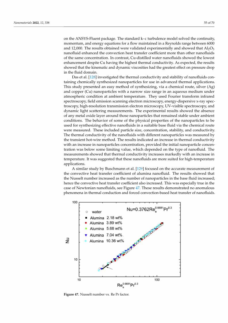
Nanomaterials 2022, 12, 338 55 of 70
on the ANSYS-Fluent package. The standard k–ε turbulence model solved the continuity,momentum, and energy equations for a flow maintained in a Reynolds range between 6000and 12,000. The results obtained were validated experimentally and showed that Al2O3nanofluid enhanced the convection heat transfer coefficient more than other nanofluidsof the same concentration. In contrast, Cu-distilled water nanofluids showed the lowestenhancement despite Cu having the highest thermal conductivity. As expected, the resultsshowed that the kinematic and dynamic viscosities had the greatest effect on pressure dropin the fluid domain.
Das et al. [128] investigated the thermal conductivity and stability of nanofluids con-taining chemically synthesized nanoparticles for use in advanced thermal applications.This study presented an easy method of synthesizing, via a chemical route, silver (Ag)and copper (Cu) nanoparticles with a narrow size range in an aqueous medium underatmospheric condition at ambient temperature. They used Fourier transform infraredspectroscopy, field emission scanning electron microscopy, energy-dispersive x-ray spec-troscopy, high-resolution transmission electron microscopy, UV–visible spectroscopy, anddynamic light scattering measurements. The experimental results showed the absenceof any metal oxide layer around those nanoparticles that remained stable under ambientconditions. The behavior of some of the physical properties of the nanoparticles to beused for synthesizing effective nanofluids in a suitable base fluid via the chemical routewere measured. These included particle size, concentration, stability, and conductivity.The thermal conductivity of the nanofluids with different nanoparticles was measured bythe transient hot-wire method. The results indicated an increase in thermal conductivitywith an increase in nanoparticles concentration, provided the initial nanoparticle concen-tration was below some limiting value, which depended on the type of nanofluid. Themeasurements showed that thermal conductivity increases markedly with an increase intemperature. It was suggested that these nanofluids are more suited for high-temperatureapplications.
A similar study by Buschmann et al. [129] focused on the accurate measurement ofthe convective heat transfer coefficient of alumina nanofluid. The results showed thatthe Nusselt number increased as the number of nanoparticles in the base fluid increased;hence the convective heat transfer coefficient also increased. This was especially true in thecase of Newtonian nanofluids, see Figure 47. These results demonstrated no anomalousphenomena in thermal conduction and forced convection-based heat transfer of nanofluids.
Nanomaterials 2022, 12, x FOR PEER REVIEW 55 of 70
A similar study by Buschmann et al. [129] focused on the accurate measurement of the convective heat transfer coefficient of alumina nanofluid. The results showed that the Nusselt number increased as the number of nanoparticles in the base fluid increased; hence the convective heat transfer coefficient also increased. This was especially true in the case of Newtonian nanofluids, see Figure 47. These results demonstrated no anoma-lous phenomena in thermal conduction and forced convection-based heat transfer of nanofluids.
Figure 47. Nusselt number vs. Re Pr factor.
Bouguerra et al. [130] measured the thermal conductivity and dynamic viscosity of alumina/water-based nanofluids at concentrations, φ, ranging from 0.2 to 2.0 vol.% using a simple measurement simulator. The results showed that five dispersion regimes were identified based on the pH values for intermediate values of the volume concentration. The well-dispersed regime characterized by a local maximum of the thermal conductivity and an absolute minimum of the dynamic viscosity was not found for 2.0 vol.%, while the chain-like agglomeration regime was not observed for 0.2 vol.%. Although there are al-ready many models for predicting the thermal conductivity of nanoparticle suspensions, most of them only consider the cases for high nanoparticle volume fractions (often 1.0 vol.%). The results obtained by Bouguerra et al. showed that for optimized nanofluids, comparable efficiency may be achieved at concentrations as low as 0.2 vol.%.
The prediction of the thermal conductivity of water-based oxide nanofluids with low volume fractions was investigated experimentally by Jin et al. [131]. The results showed that the famous multi-sphere Brownian model showed large deviations when predicting thermal conductivity for particle concentrations below 0.1 vol.%. The predicted thermal conductivity can be in good agreement with experimental data for the particle volume fractions ranging up to 10 vol.%. Liu et al. [132] studied the effect of SiO2, TiO2, and Al2O3 nanoparticles in water as the base fluid on the convective heat transfer coefficients. A dou-ble layer concentric glass tube was used for the study, allowing no contact between cool-ant and hot fluid. It was found that by adding nanoparticles, the convective heat transfer coefficient of water can generally be enhanced. A 45% increase was achieved with 0.5 vol.% of Al2O3 nanoparticles at an intermediate Reynolds number of around 4100. It was found that reducing nanoparticle size and increasing the nanofluid flow rate increased the improvement in heat transfer. It was concluded that the enhancement depended on the
Figure 47. Nusselt number vs. Re Pr factor.
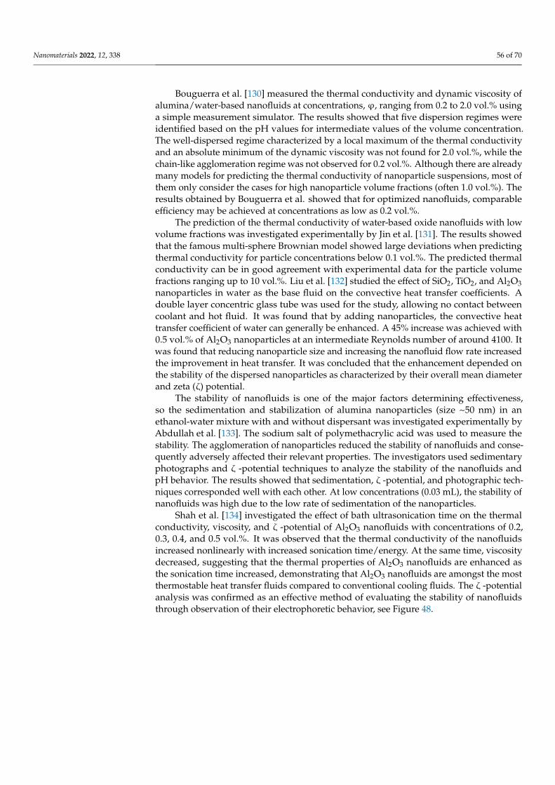
Nanomaterials 2022, 12, 338 56 of 70
Bouguerra et al. [130] measured the thermal conductivity and dynamic viscosity ofalumina/water-based nanofluids at concentrations, ϕ, ranging from 0.2 to 2.0 vol.% usinga simple measurement simulator. The results showed that five dispersion regimes wereidentified based on the pH values for intermediate values of the volume concentration.The well-dispersed regime characterized by a local maximum of the thermal conductivityand an absolute minimum of the dynamic viscosity was not found for 2.0 vol.%, while thechain-like agglomeration regime was not observed for 0.2 vol.%. Although there are alreadymany models for predicting the thermal conductivity of nanoparticle suspensions, most ofthem only consider the cases for high nanoparticle volume fractions (often 1.0 vol.%). Theresults obtained by Bouguerra et al. showed that for optimized nanofluids, comparableefficiency may be achieved at concentrations as low as 0.2 vol.%.
The prediction of the thermal conductivity of water-based oxide nanofluids with lowvolume fractions was investigated experimentally by Jin et al. [131]. The results showedthat the famous multi-sphere Brownian model showed large deviations when predictingthermal conductivity for particle concentrations below 0.1 vol.%. The predicted thermalconductivity can be in good agreement with experimental data for the particle volumefractions ranging up to 10 vol.%. Liu et al. [132] studied the effect of SiO2, TiO2, and Al2O3nanoparticles in water as the base fluid on the convective heat transfer coefficients. Adouble layer concentric glass tube was used for the study, allowing no contact betweencoolant and hot fluid. It was found that by adding nanoparticles, the convective heattransfer coefficient of water can generally be enhanced. A 45% increase was achieved with0.5 vol.% of Al2O3 nanoparticles at an intermediate Reynolds number of around 4100. Itwas found that reducing nanoparticle size and increasing the nanofluid flow rate increasedthe improvement in heat transfer. It was concluded that the enhancement depended onthe stability of the dispersed nanoparticles as characterized by their overall mean diameterand zeta (ζ) potential.
The stability of nanofluids is one of the major factors determining effectiveness,so the sedimentation and stabilization of alumina nanoparticles (size ~50 nm) in anethanol-water mixture with and without dispersant was investigated experimentally byAbdullah et al. [133]. The sodium salt of polymethacrylic acid was used to measure thestability. The agglomeration of nanoparticles reduced the stability of nanofluids and conse-quently adversely affected their relevant properties. The investigators used sedimentaryphotographs and ζ -potential techniques to analyze the stability of the nanofluids andpH behavior. The results showed that sedimentation, ζ -potential, and photographic tech-niques corresponded well with each other. At low concentrations (0.03 mL), the stability ofnanofluids was high due to the low rate of sedimentation of the nanoparticles.
Shah et al. [134] investigated the effect of bath ultrasonication time on the thermalconductivity, viscosity, and ζ -potential of Al2O3 nanofluids with concentrations of 0.2,0.3, 0.4, and 0.5 vol.%. It was observed that the thermal conductivity of the nanofluidsincreased nonlinearly with increased sonication time/energy. At the same time, viscositydecreased, suggesting that the thermal properties of Al2O3 nanofluids are enhanced asthe sonication time increased, demonstrating that Al2O3 nanofluids are amongst the mostthermostable heat transfer fluids compared to conventional cooling fluids. The ζ -potentialanalysis was confirmed as an effective method of evaluating the stability of nanofluidsthrough observation of their electrophoretic behavior, see Figure 48.
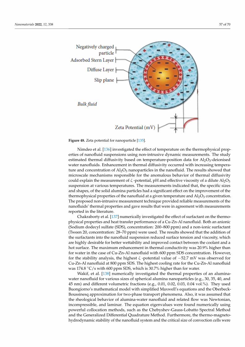
Nanomaterials 2022, 12, 338 57 of 70
Nanomaterials 2022, 12, x FOR PEER REVIEW 56 of 70
stability of the dispersed nanoparticles as characterized by their overall mean diameter and zeta (ζ) potential.
The stability of nanofluids is one of the major factors determining effectiveness, so the sedimentation and stabilization of alumina nanoparticles (size ~50 nm) in an ethanol-water mixture with and without dispersant was investigated experimentally by Abdullah et al. [133]. The sodium salt of polymethacrylic acid was used to measure the stability. The agglomeration of nanoparticles reduced the stability of nanofluids and consequently ad-versely affected their relevant properties. The investigators used sedimentary photo-graphs and ζ -potential techniques to analyze the stability of the nanofluids and pH be-havior. The results showed that sedimentation, ζ -potential, and photographic techniques corresponded well with each other. At low concentrations (0.03 mL), the stability of nanofluids was high due to the low rate of sedimentation of the nanoparticles.
Shah et al. [134] investigated the effect of bath ultrasonication time on the thermal conductivity, viscosity, and ζ -potential of Al2O3 nanofluids with concentrations of 0.2, 0.3, 0.4, and 0.5 vol.%. It was observed that the thermal conductivity of the nanofluids in-creased nonlinearly with increased sonication time/energy. At the same time, viscosity decreased, suggesting that the thermal properties of Al2O3 nanofluids are enhanced as the sonication time increased, demonstrating that Al2O3 nanofluids are amongst the most thermostable heat transfer fluids compared to conventional cooling fluids. The ζ -poten-tial analysis was confirmed as an effective method of evaluating the stability of nanofluids through observation of their electrophoretic behavior, see Figure 48.
Figure 48. Zeta potential for nanoparticle [135].
Nimdeo et al. [136] investigated the effect of temperature on the thermophysical properties of nanofluid suspensions using non-intrusive dynamic measurements. The study estimated thermal diffusivity based on temperature-position data for Al2O3-deion-ised water nanofluids. Enhancement in thermal diffusivity occurred with increasing tem-perature and concentration of Al2O3 nanoparticles in the nanofluid. The results showed that microscale mechanisms responsible for the anomalous behavior of thermal diffusivity could explain the measurement of ζ -potential, pH and effective viscosity of a dilute Al2O3 suspension at various temperatures. The measurements indicated that, the specific sizes and shapes, of the solid alumina particles had a significant effect on the improvement of the thermophysical properties of the nanofluid at a given temperature and Al2O3 concen-tration. The proposed non-intrusive measurement technique provided reliable
Figure 48. Zeta potential for nanoparticle [135].
Nimdeo et al. [136] investigated the effect of temperature on the thermophysical prop-erties of nanofluid suspensions using non-intrusive dynamic measurements. The studyestimated thermal diffusivity based on temperature-position data for Al2O3-deionisedwater nanofluids. Enhancement in thermal diffusivity occurred with increasing tempera-ture and concentration of Al2O3 nanoparticles in the nanofluid. The results showed thatmicroscale mechanisms responsible for the anomalous behavior of thermal diffusivitycould explain the measurement of ζ -potential, pH and effective viscosity of a dilute Al2O3suspension at various temperatures. The measurements indicated that, the specific sizesand shapes, of the solid alumina particles had a significant effect on the improvement of thethermophysical properties of the nanofluid at a given temperature and Al2O3 concentration.The proposed non-intrusive measurement technique provided reliable measurements of thenanofluids’ thermal properties and gave results that were in agreement with measurementsreported in the literature.
Chakraborty et al. [137] numerically investigated the effect of surfactant on the thermo-physical properties and heat transfer performance of a Cu-Zn-Al nanofluid. Both an anionic(Sodium dodecyl sulfate (SDS), concentration: 200–800 ppm) and a non-ionic surfactant(Tween 20, concentration: 28–70 ppm) were used. The results showed that the addition ofthe surfactants into the nanofluid suspension reduced surface tension and viscosity, whichare highly desirable for better wettability and improved contact between the coolant and ahot surface. The maximum enhancement in thermal conductivity was 20.9% higher thanfor water in the case of Cu-Zn-Al nanofluid with 600 ppm SDS concentration. However,for the stability analysis, the highest ζ -potential value of −52.7 mV was observed forCu-Zn-Al nanofluid at 800 ppm SDS. The highest cooling rate for the Cu-Zn-Al nanofluidwas 174.8 ◦C/s with 600 ppm SDS, which is 30.7% higher than for water.
Wakif, et al. [138] numerically investigated the thermal properties of an alumina-water nanofluid for various sizes of spherical alumina nanoparticles (e.g., 30, 35, 40, and45 nm) and different volumetric fractions (e.g., 0.01, 0.02, 0.03, 0.04 vol.%). They usedBuongiorno’s mathematical model with simplified Maxwell’s equations and the Oberbeck-Boussinesq approximation for two-phase transport phenomena. Also, it was assumed thatthe rheological behavior of alumina-water nanofluid and related flow was Newtonian,incompressible, and laminar. The equation eigenvalues were found numerically usingpowerful collocation methods, such as the Chebyshev-Gauss-Lobatto Spectral Methodand the Generalized Differential Quadrature Method. Furthermore, the thermo-magneto-hydrodynamic stability of the nanofluid system and the critical size of convection cells were
Nanomaterials 2022, 12, 338 58 of 70
highlighted graphically in terms of critical thermal wave numbers. The results indicatedthat stability increases for very small particles and increases in the nanofluid temperaturebut decreases as concentration and PH increase, especially at low temperatures.
Carbon Nanotubes
The previous section covered literature relevant to the thermophysical properties ofdifferent nanofluids. In this section, the main focus is on Carbon Nanotubes, because thesenanoparticles have very high conductivity and have recently attracted the attention ofmany researchers.
Carbon nanotubes (CNTs) are tubular carbon-based allotropes that can be producedfrom graphitic carbon and used in nanofluids for heat transfer applications. There are differ-ent types of CNTS, single-walled graphene cylinders (SWCNTs), double-walled (DWCNT)consisting of two nested cylinders, and multi-walled carbon nanotubes (MWCNTs) ofseveral nested cylinders [139,140]. CNTs can be produced by decomposition of carbon-containing compounds such as C2H2, CH4, C2H4 or C2H6, over metal particles (catalysts),with growth occurring at the base or the tip of the tube in a needle-like structure. This proce-dure is based on using catalytic chemical vapor deposition. Chemical reaction time directlyaffects the length of the carbon tube, while tube diameter is determined by the diameter ofthe particle on which growth occurs [141]. The enhancement in thermal conductivity ofworking fluids used in thermal systems by introducing SWCNTs with a nanocoating of Niwas discussed by Wright et al. [142]. It was found that the nanofluid with coated nanotubeshad a higher overall heat transfer coefficient due to the increase in the wall thermal conduc-tivity. Wright et al. [142] fabricated nanofluids using self-assembly techniques and thenmeasured the physical properties experimentally. This study considered nanofluid flow asfrictionless transport and showed that properties such as thermal conductivity, viscosity,stability, acidity, and pH depended on nanoparticle concentration the techniques used toproduce them.
Asadi and Alarifi focused on the effects of ultrasonication on the thermophysicalproperties of MWCNTs-water nanofluids [143]. Their results showed that increasing theultrasonication time to 60 min leads to decreasing the dynamic viscosity of the samples.Based on their results, the maximum increase in fanning friction factor ratio is less than 3%,which indicates that adding MWCNTs to water does not significantly affect the requiredpumping power.
CNTs manufactured by catalytic decomposition typically show large thicknesses,often consisting of large particle aggregates. CNT production techniques were extensivelyresearched, including arc-discharge, laser ablation, pyrolysis, and enhanced plasma vapordeposition. The main problem was the poor resulting dispersion, with high instability,which can lead to the agglomeration of the nanoparticles. To minimize the effects of poordispersion, steric barriers (surfactants) are typically employed (Eastman [144]).
Goodarzi et al. [145] investigated the influence of different functional covalent groupson the thermophysical properties of a MWCNT-water nanofluid. Cysteine (Cys) andsilver (Ag) were covalently attached to the surface of the MWCNTs. To determine thethermal properties, different water-based nanofluids such as Gum Arabic treated MWCNTs,functionalized MWCNTs using cysteine (FMWCNTs-Cys) and silver (FMWCNTs-Ag), wereemployed as coolants in a counter flow, corrugated plate HE. It was found that increasingthe Reynolds number, Peclet number, or volume fraction improved the heat transfercharacteristics of the nanofluid. At volume concentrations of 1.0%, there was minimaldifference in the increase in heat transfer coefficients obtained at minimum and maximumPeclet numbers: the claimed enhancements were, 41.3073% and 41.3058% respectively.
The investigations conducted on plate HEs show how well nanofluids performed interms of heat transfer characteristics. Based on the obtained results, it can be concluded thatheat transfer coefficients increase with an increase in the volume fraction of nanoparticles,at least up to a certain percentage. Nevertheless, a few studies are not consistent with thisfinding and have concluded that heat transfer efficacy is enhanced by reducing the concen-
Nanomaterials 2022, 12, 338 59 of 70
tration of nanoparticles, but increasing Reynolds number and Peclet number. Because oftheir plates, plate HEs have more geometric parameters than other heat exchangers. Forthis reason, many of the studies conducted on the application of nanofluids in plate HEshave focused on their geometric characteristics.
Seth et al. [146] carried out research that simulated the influence of magnetic fieldand volume fraction of CNTs on the flow over a stretched sheet in a rotating frame, whichis pertinent to gas turbines. The study analyzed the behavior of a base fluid of waterwith both MWCNTs and SWCNTs, using a mathematical model developed by order ofmagnitude analysis. The research included numerical simulation of the fluid velocity,temperature, Nusselt number and skin friction coefficient for a set of values of differentregulatory flow parameters to replicate the physics of the flow. The research concluded thatthe fluid velocities for SWCNTs and MWCNTs are lowered with incremental changes tothe governing flow parameters, such as porosity and inertia coefficients. The investigatorspointed out that nanoparticles used ranged in size from 1 to 100 nm.
Given that the thermal performance of conventional working fluids such as oil andwater is poor, nanofluids with strong thermal properties can greatly improve thermaltransfer. It was found that there was a reduction in primary fluid velocity with bothSWCNTs and MWCNTs due to an increase in rotational parameters. It was also found thatthe fluid temperature was enhanced for both SWCNTs and MWCNTs with an increase inthe nanoparticle volume fraction. The primary skin friction coefficient was also enhancedby strengthening the regulatory flow parameters. The study revealed that there was asignificant increase in thermal energy irreversibility, as measured by the Bejan number, nearthe stretching surface. The conclusion drawn from these findings is that the presence of anapplied magnetic field when using a nanofluid containing either SWCNTs and MWCNTsincreases the thermal energy’s irreversibility in terms of Bejan number.
Hayat et al. [147] maintain that as CNTs comprise rolled graphene sheets, the materialconsists of carbon chains that do not pose a risk to the atmosphere. The hexagonal carbonmolecules have significant properties that can be exploited for heat transfer, includingthermal conductivity. They also exhibit high levels of corrosion resistance and significantmechanical strength, and electrical conductivity. These properties mean that CNTs areuseful in a wide range of applications, such as catalyst supports and energy storage, sensors,and thermal material.
Arzani et al. [148] studied the thermophysical properties, including the heat transferrate, of covalently functionalized MWCNTs-nanofluids in an annular heat exchanger asused in gas turbines. The study aimed to develop a novel method for improving theirperformance with respect to heat transfer effectiveness by preparing highly-dispersedcarbon nanotubes. The project used aspartic acid, acting as a hydrophilic group, to func-tionalize the MWCNTs to produce a highly dispersed colloidal suspension covalently. TheMWCNTs were stirred in a mixture of H2SO4–HNO3 acids with volume ratio of 1:1 for24 h at a temperature of 60 ◦C. The solution was then filtered and rinsed with deionizedwater, after which the filtrate cake was dried. Then, 1 g of oxidized MWCNT and 1 g ofaspartic acid were placed in 200 mL DMF with 10 mL toluene for 2 h and then stirred for12 h, using ZrCl4 (5% mol) as a catalyst to increase the rate of the reaction. The resultingsuspension was then filtered and rinsed with deionized water and dried in the oven for48 h at 50 ◦C. To synthesize the MWCNT-Asp/water nanofluids, the MWCNT-Asp wasinitially dispersed in deionized water for 1 h using an ultrasonic probe. Arzani et al. [148]assessed the dispersion state as well as the long-term stability of the MWCNT-Asp/watercoolants for different weight fractions and concluded that there is an insignificant decreasein the relative concentration of MWCNT-Asp over time, which, they argued, confirmed thesuitable dispersibility of MWCNT-Asp in water.
The results also showed that the density of the prepared MWCNT-Asp/water nanofluidincreased with increased temperature and concentration. The results again confirmed thatusing a nanofluid improved heat transfer performance compared to water. Generally, thethermal conductivity of the nanofluids improved with increasing MWCNT-Asp, and it
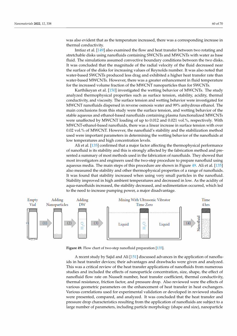
Nanomaterials 2022, 12, 338 60 of 70
was also evident that as the temperature increased, there was a corresponding increase inthermal conductivity.
Imtiaz et al. [149] also examined the flow and heat transfer between two rotating andstretchable disks using nanofluids containing SWCNTs and MWCNTs with water as basefluid. The simulations assumed convective boundary conditions between the two disks.It was concluded that the magnitude of the radial velocity of the fluid decreased nearthe surface of the disks for increasing values of Reynolds number. It was also noted thatwater-based SWCNTs produced less drag and exhibited a higher heat transfer rate thanwater-based MWCNTs. However, there was a greater enhancement in fluid temperaturefor the increased volume fraction of the MWCNT nanoparticles than for SWCNTs.
Karthikeyan et al. [150] investigated the wetting behavior of MWCNTs. The studyanalyzed thermophysical properties such as surface tension, stability, acidity, thermalconductivity, and viscosity. The surface tension and wetting behavior were investigated forMWCNT nanofluids dispersed in reverse osmosis water and 99% anhydrous ethanol. Themain conclusions from this study were the surface tension, and wetting behavior of thestable aqueous and ethanol-based nanofluids containing plasma functionalized MWCNTswere unaffected by MWCNT loading of up to 0.012 and 0.021 vol.%, respectively. WithMWCNT-ethanol-based nanofluids, there was a linear increase in surface tension with over0.02 vol.% of MWCNT. However, the nanofluid’s stability and the stabilization methodused were important parameters in determining the wetting behavior of the nanofluids atlow temperatures and high concentration levels.
Ali et al. [135] confirmed that a major factor affecting the thermophysical performanceof nanofluid is its stability and this is strongly affected by the fabrication method and pre-sented a summary of most methods used in the fabrication of nanofluids. They showed thatmost investigators and engineers used the two-step procedure to prepare nanofluid usingaqueous media. The main steps of this procedure are shown in Figure 49. Ali et al. [135]also measured the stability and other thermophysical properties of a range of nanofluids.It was found that stability increased when using very small particles in the nanofluid.Stability improved in high ambient temperatures and decreased in low. As the acidity ofaqua-nanofluids increased, the stability decreased, and sedimentation occurred, which ledto the need to increase pumping power, a major disadvantage.
Nanomaterials 2022, 12, x FOR PEER REVIEW 60 of 70
acidity of aqua-nanofluids increased, the stability decreased, and sedimentation occurred, which led to the need to increase pumping power, a major disadvantage.
Figure 49. Flow chart of two-step nanofluid preparation [135].
A recent study by Sajid and Ali [151] discussed advances in the application of nanofluids in heat transfer devices; their advantages and drawbacks were given and ana-lyzed. This was a critical review of the heat transfer applications of nanofluids from nu-merous studies and included the effects of nanoparticle concentration, size, shape, the ef-fect of nanofluid flow rate on Nusselt number, heat transfer coefficient, thermal conduc-tivity, thermal resistance, friction factor, and pressure drop. Also reviewed were the ef-fects of various geometric parameters on the enhancement of heat transfer in heat ex-changers. Various correlations used for experimental validation or developed in reviewed studies were presented, compared, and analyzed. It was concluded that the heat transfer and pressure drop characteristics resulting from the application of nanofluids are subject to a large number of parameters, including particle morphology (shape and size), nano-particle type, nanofluid preparation method, surfactants, stability of nanoparticles in the base fluid and, more significantly, on volume concentration of nanoparticles and flow rate of the nanofluid. It appears there is an optimum concentration of nanoparticles that leads to optimum stability, heat transfer, pH, and thermal conductivity.
Most investigators have indicated an improvement in heat transfer rate with an in-crease in flow rate of the nanofluid due to a boost in forced convection due to increased turbulence in the fluid, better mixing, and inter-collision of nanoparticles. A few studies recommended using very small nanoparticles, claiming better effect heat transfer perfor-mance and less friction. The friction factor is increased with the increased density and viscosity of the nanofluid. It is apparent from the above studies that nanofluids have mas-sive potential in practical applications. However, many aspects require more in-depth re-search, such as the effects of the addition of surfactant on the heat transfer characteristics of nanofluids, which presently are not well understood or explained. Measured accurate thermal conductivity, stability, pH, density, and nanofluid viscosity are not yet possible.
7. Gaps in Present Knowledge To produce compact, high-performance heat exchangers suitable for use in the pro-
pulsion system of a marine gas turbine, it is necessary to enhance the internal heat transfer of the coolant fluid. Although many research studies have investigated the use of nanoflu-ids in heat exchangers to enhance thermal conductivity, there exists plenty of controversy and inconsistencies among the reported results. Many challenges face the successful ap-plications of nanofluids.
The conclusion of most heat transfer investigations that used nanofluids is that the understanding of the behavior of nano-particles in base-fluids is still quite limited, espe-cially their stability and thermo-chemical properties. Also, the most suitable concentration of nanoparticles to use with a particular base fluid needs investigation, as does the opti-mum velocity flow in given heat exchangers, such as those that might be applied to WR-21 gas turbines. Other questions that need answering include: what nanofluids can be
Figure 49. Flow chart of two-step nanofluid preparation [135].
A recent study by Sajid and Ali [151] discussed advances in the application of nanoflu-ids in heat transfer devices; their advantages and drawbacks were given and analyzed.This was a critical review of the heat transfer applications of nanofluids from numerousstudies and included the effects of nanoparticle concentration, size, shape, the effect ofnanofluid flow rate on Nusselt number, heat transfer coefficient, thermal conductivity,thermal resistance, friction factor, and pressure drop. Also reviewed were the effects ofvarious geometric parameters on the enhancement of heat transfer in heat exchangers.Various correlations used for experimental validation or developed in reviewed studieswere presented, compared, and analyzed. It was concluded that the heat transfer andpressure drop characteristics resulting from the application of nanofluids are subject to alarge number of parameters, including particle morphology (shape and size), nanoparticle
Nanomaterials 2022, 12, 338 61 of 70
type, nanofluid preparation method, surfactants, stability of nanoparticles in the base fluidand, more significantly, on volume concentration of nanoparticles and flow rate of thenanofluid. It appears there is an optimum concentration of nanoparticles that leads tooptimum stability, heat transfer, pH, and thermal conductivity.
Most investigators have indicated an improvement in heat transfer rate with an in-crease in flow rate of the nanofluid due to a boost in forced convection due to increasedturbulence in the fluid, better mixing, and inter-collision of nanoparticles. A few studiesrecommended using very small nanoparticles, claiming better effect heat transfer perfor-mance and less friction. The friction factor is increased with the increased density andviscosity of the nanofluid. It is apparent from the above studies that nanofluids havemassive potential in practical applications. However, many aspects require more in-depthresearch, such as the effects of the addition of surfactant on the heat transfer characteristicsof nanofluids, which presently are not well understood or explained. Measured accuratethermal conductivity, stability, pH, density, and nanofluid viscosity are not yet possible.
7. Gaps in Present Knowledge
To produce compact, high-performance heat exchangers suitable for use in the propul-sion system of a marine gas turbine, it is necessary to enhance the internal heat transfer ofthe coolant fluid. Although many research studies have investigated the use of nanofluidsin heat exchangers to enhance thermal conductivity, there exists plenty of controversyand inconsistencies among the reported results. Many challenges face the successfulapplications of nanofluids.
The conclusion of most heat transfer investigations that used nanofluids is that the un-derstanding of the behavior of nano-particles in base-fluids is still quite limited, especiallytheir stability and thermo-chemical properties. Also, the most suitable concentration ofnanoparticles to use with a particular base fluid needs investigation, as does the optimumvelocity flow in given heat exchangers, such as those that might be applied to WR-21 gasturbines. Other questions that need answering include: what nanofluids can be safely usedin an intercooler, what is the optimum concentration of nanoparticles, what corrosion is aparticular nanofluid likely to cause, what operating conditions will cause the least fouling,what measures can be taken to minimize fouling when using nanofluids, what should bethe flow Re number, what the best intercooler effectiveness to use with nanofluids? Also,the effect of nanoparticles on the friction factor of flow through intercooler tubes needssignificant experimental investigation.
The intercooler technologies used in gas turbines are well-established, but thereis still an ongoing demand for more compact, low-pressure loss, more effective heatexchangers. Intercoolers are mainly deployed in stationary and marine gas turbines, butbulky intercooler installations limit their applications. Increasing the size of an intercoolermay require an increase in space occupied by the engine this can increase installation lossesand add to shaft lengths, which increases the likelihood of vibration problems.
In most of the literature reviewed, one way was used to produce the nanofluids to beused as a heat transfer medium. The preparation is crucial as it can result in a completelydifferent nanofluid in terms of its thermophysical properties (i.e., acidity, settling behavior,and particle agglomeration) but it is noted that there is a lack of agreement on controllingthe temperature of the base fluid containing the nano-particles during the preparationphase when using an ultrasonicator. Using an ultrasonicator for fabricating nanofluidsgenerally produces a gradual increase in the temperature of the prepared fluid, which isstrongly influenced by the surrounding ambient temperature, which may vary with timeof day and season of the year. This variation can result in the production of nanofluids ofdiverse thermophysical properties.
A key finding in most of the literature reviewed was that the use of nanofluids inapplications at elevated temperatures occasionally resulted in ‘nano-fouling’ the depositionof the nanoparticles on the surface in contact with the fluid. This type of particle build-uphas a strong impact on both wettability of the surface, its thermal conductivity, and surface
Nanomaterials 2022, 12, 338 62 of 70
roughness. The latter can directly impact the pumping pressure and can be a big problem.Therefore, an investigation is required of nanofluid fouling problems as a function of thefabrication method, particularly by controlling the operating temperature. Experimentalresearch using simulated rigs or directly with large-scale equipment such as a WR-21 engineis needed to assess whether some nanofluid particles will build up and accumulate on thesurface of the HE tubes after a short time of operation. It is also required to research andfabricate other types of nanofluids that can be used safely and effectively in intercoolersand recuperators with high operating temperatures.
There is a limited number of investigations in the reviewed literature regarding CNTnanofluids, with little in terms of the practical application of CNTs as working nanofluidsin intercoolers after the first compressor. Reports show CNT nanofluids lead to significantlyhigher heat transfer enhancement than other nanofluids and could maximize efficiencieswhen used in the intercoolers of a WR-21. Studies of CNTs in plate-fin HEs are still neededto better understand the thermophysical processes involved. There have been some recentstudies into heat pipes and shell-and-tube HEs that can be applied to recuperators. Manyresearchers have used Cu, Fe3O4, and Al2O3 particles as secondary materials in HEsoperating in low-temperature ranges.
Questions regarding using CNT nanofluids in the intercooler of a WR-21 still need tobe posed and answered. The reported research strongly suggests that using nanofluidscan improve thermal transfer, reduce pressure drop, while they remain stable. The impactdepends on the vol.% of nanoparticles in the nanofluid and the base fluid density.
Finally, it is clear there is a significant gap in current knowledge on the use of nanoflu-ids as a secondary heat transfer material, especially in intercoolers (plate-fin HE) used inthe application of marine gas turbine power plants. It is hoped that this review has, atleast, addressed part of this gap. So, a primary aim of current research being undertaken atCranfield University, School of Aerospace, Transport and Manufacturing will be to investi-gate experimentally and numerically the application of CNT nanofluids to convective heattransfer in plate-fin HEs (intercoolers) for use in marine gas turbine power plants operatingat high temperatures.
8. Conclusions
This review has covered aspects of gas turbine technology, mainly the introduction ofintercoolers with advanced working fluids in the form of nanofluids to the cycle. As such,the main conclusion is divided into three parts, as follows:
8.1. Gas Turbine Technology
Designing a complete marine gas turbine system is complex due to the many inter-actions involving consideration of different and sometimes conflicting physical, chemical,material, and design requirements. Military and commercial competition ensures continu-ous improvement in performance and operating conditions and present designs are theresult of decades of research and development and contain several commonly used ar-rangements, including the simple cycle, which remains the standard layout; the intercoolercycle, which adds an intercooler to the standard cycle for increased performance; the ICRcycle, which uses a recuperator to recover heat from the exhaust of the gas turbine; thereheat cycle, which adds a reheat combustor to the standard cycle; an intercooled reheatcycle, which is a combination of intercooled and reheat cycle configurations; and combinedcycle. The review found that the ICR is optimal for marine applications and is used in theWR-21. On the other hand, Gradient-based optimization techniques seem to provide asolution. These techniques rely on gradient information; how the performance changeswhen infinitesimal changes to the design variables are made [152].
Most previous works were based on increasing compression, turbine inlet temperature,and overall pressure ratio. But these factors are limited because they depend on thespecifications of the materials used, cooling technology, and cost. However, analyticalresults showed that maximum thermal efficiency required entropy generation per unit
Nanomaterials 2022, 12, 338 63 of 70
work output to be a minimum, which required improvement in the Brayton cycle operationand design parameters such as the effectiveness of the intercoolers and recuperators. It hasbeen shown that small value of recuperator effectiveness means the thermal efficiency ofthe cycle would also be small.
Using an intercooler in marine gas turbine propulsion plants is very effective due toits direct effect on the overall efficiency of the cycle, whereas decreasing the work input tothe compression process requires very high recuperator effectiveness. However, using in-tercooling in a gas turbine propulsion system without reheat causes a decrease in efficiency(at least for small pressure ratios) due to the drop in air temperature after the compres-sor. Overall results show that reducing the net specific work input required for a givenpressure ratio improved the performance of the cycle. As a general case, the intercoolerbenefits the Brayton cycle gas turbine power plant by decreasing the compression workof the high-pressure compressor, which allows for higher pressure ratios, thus increasingoverall efficiency.
The current direction of marine power system development is taking a differentdirection such as design specification, manufacturing efficient energy systems, and usingbetter operating conditions.
The WR-21 is a development of the aero and industrial RB211 family of engines andmeets current Royal Navy ICR requirements. New designs based on the WR-21 usingefficient, super materials for the gas turbine blades will enable higher engine capacities forcargo vehicles. An essential element in developing the WR-21 could be to use nanofluids toimprove thermo-fluid flow performance and reduce overall costs.
8.2. Heat Exchanger
The gas turbine plays a key role in power generation, with its basic cycle involvingthree main components: compressor, combustion chamber, and turbine. The overall perfor-mance of the gas turbine depends on the efficiency of each component and the workingtemperature of the turbine. An attraction of such a design is that while each componentaffects the efficiency of the overall unit, it is possible to develop the different componentsgas turbine separately. For example, improving the performance of the heat exchangers(e.g., intercooler and recuperator) will increase the power output and efficiency. However,any changes of an individual component will impact the overall performance, such asincreasing design complexity, weight, size, cost, and raising manufacturing, maintenance,and safety issues.
An important element in the intercooler is choosing the heat exchanger from varioustypes, materials, and configurations. The selection depends on the heat transfer raterequired and the base fluid. Considerable research has been carried out to identify and selectthe optimal type of heat exchanger. However, the process is complex, and further researchis needed to reduce the HE weight and size while simultaneously improving its efficiency,especially in marine and aero-technology applications. The main factor for classifying a HEis its effectiveness rating used to estimate its thermo-hydraulic performance. The designparameters of HEs have usually been based on heat exchanger geometry and materialproperties. Recently operating conditions such as working fluid flow rate, temperature,thermal conductivity, stability, and viscosity (pressure drop) have become important.
There are different ways to increase HE performance, such as increasing the heattransfer rate between the two sides in indirect systems using one of the following: increasingthe heat transfer coefficients, increasing exchanger surface area, increasing working fluidthermal conductivity, and increasing the temperature gradient. For example, a shell-and-tube HE increases the tube-side heat transfer coefficient by increasing the fluid velocityor increasing the number of tube passes. The shell-side heat transfer coefficient can beincreased by decreasing baffle spacing and/or baffle cut. It may be possible to increase theheat transfer surface area by increasing the length of the HE, increasing the shell diameter,or using multiple shells in series. On the other hand, using alternative working fluids is
Nanomaterials 2022, 12, 338 64 of 70
very effective, especially nanofluids where Fe3O4, Cu, CNTs, etc., nanoparticles are addedto a working fluid to improve its thermophysical properties.
Extensive experimental and theoretical efforts have been made to obtain solutions forturbulent forced convection heat transfer and flow friction problems in HEs. There are manyempiric correlations available in the literature for fully developed (hydro-dynamically andthermally) turbulent single- and two-phase flow with constant physical properties of thefluids. These existing correlations can be used in the design of HEs subject to the limitationsimposed on their applicability. Also, much scientific effort has been put into determiningempirical correlations that give good agreement with experimental data and can be usedto estimate heat transfer coefficients and the effectiveness of HEs directly. In addition,applying these correlations should not increase the pressure drop across the HE. Reducingthe pressure drop can be achieved by decreasing the number of tube passes, increasing tubediameter, decreasing tube length, using very smooth material, optimizing the nanofluidconcentration, and/or minimizing the Renumber.
Most published literature covers methods of increasing HE effectiveness. Still, themain limitation of heat transfer enhancement techniques is the poor thermal performanceof the working fluids, obstructing increases in performance and compactness of HEs. Thefundamental thermophysical properties of fluids are convective heat transfer, thermalconductivity, viscosity, and specific heat at constant pressure. Of the available literature,most studies have focused on forced convective heat transfer coefficient and Nusseltnumber, which depends on the Prandtl and Reynolds numbers of nanofluids in HEsconsisting of circular tubes. The convective heat transfer coefficient depends on thermalconductivity, specific heat capacity, viscosity, flow rate, and density of the fluids. The fluidflow regime and temperature are of utmost importance, and studies have been conductedfor both laminar and turbulent flow regimes.
8.3. Nanofluids Technology Subsection Shell-and-Tube Heat Exchangers
Most nanofluids used in heat transfer and energy conversion systems such as HEsare used to enhance the thermophysical properties of the working fluids such as water,air, and oil. The added nanoparticles improve the thermophysical properties such asthermal conductivity, specific heat, and heat capacity. Still, they can have negative effectsby increasing the viscosity of the base fluid, increasing the friction factor, and fouling thesystem with sediment, all of which increase the pressure drop across the heat exchangerand require additional pumping power to circulate the working fluid at the required rate.
There has been significantly less attention given to investigating the convective heattransfer of nanofluids and possible enhancement factors needed to enable the practicalapplication of nanofluids to heat exchangers with high working temperatures and pressuressuch as in intercooler-recuperators of gas turbine systems. Of the limited number ofavailable studies, most report relative enhancement of convective coefficients with respectto thermal conductivities for the same nanofluid. This is a strong indication that other,possibly as yet unknown, factors influence the enhancement of heat transfer obtained byusing nanofluids. It is observed that all experimental studies of convective heat transferstudied nanofluid flow through circular tubes and agreed that the particle volume fractioninfluences thermal performance. However, higher particle concentrations contribute toa higher pressure drop across the HE for the same fluid flow rate, which carries theinconvenience of increased pumping requirements. So, using nanofluid in the intercooler-recuperator of a Brayton gas turbine cycle will require considerable investigation, especiallypractical studies.
8.4. Future Work
Based on the literature review, researchers should focus on measurement methods andtechnologies for the accurate measurement of the thermophysical properties of nanofluids.Also, simulations should be carried out based on the measured values and more realisticassumptions to better determine the main factors that affect working fluid behavior.
Nanomaterials 2022, 12, 338 65 of 70
Author Contributions: A.A. has designed the conceptual idea and had the major contribution inSections 1–8. M.M.R., N.A. and S.A. have equally contributed to Sections 2–6. All authors have readand agreed to the published version of the manuscript.
Funding: This research received no external funding.
Institutional Review Board Statement: Not applicable.
Informed Consent Statement: Not applicable.
Data Availability Statement: The data presented in this study are available on request from thecorresponding author.
Conflicts of Interest: The authors declare no conflict of interest.
References1. Ibrahim, M.; Algehyne, E.A.; Saeed, T.; Berrouk, A.S.; Chu, Y.-M.; Cheraghian, G. Assessment of Economic, Thermal and
Hydraulic Performances a Corrugated Helical Heat Exchanger Filled with Non-Newtonian Nanofluid. Sci. Rep. 2021, 11, 11568.[CrossRef]
2. Razak, A.M.Y. 11-Gas Turbine Performance Modelling, Analysis and Optimisation. In Woodhead Publishing Series in Energy;Jansohn, P.B.T., Ed.; Woodhead Publishing: Cambridge, UK, 2013; pp. 423–514. ISBN 978-1-84569-728-0.
3. Saravanamuttoo, H.I.; Rogers, G.F.C.; Cohen, H.; Straznicky, P.V. Gas Turbine Theory; Pearson Education: Essex, UK, 2009.4. Çetin, B. Optimal Performance Analysis of Gas Turbines. Dogus Univ. J. 2011, 7, 59–71.5. Ameri, M.; Hejazi, S.H.; Montaser, K. Performance and Economic of the Thermal Energy Storage Systems to Enhance the Peaking
Capacity of the Gas Turbines. Appl. Therm. Eng. 2005, 25, 241–251. [CrossRef]6. Shi, X.; Che, D. Thermodynamic Analysis of an LNG Fuelled Combined Cycle Power Plant with Waste Heat Recovery and
Utilization System. Int. J. Energy Res. 2007, 31, 975–998. [CrossRef]7. Xie, Z.; Su, M.; Weng, S. Extensible Object Model for Gas Turbine Engine Simulation. Appl. Therm. Eng. 2001, 21, 111–118.
[CrossRef]8. Kurt, H.; Recebli, Z.; Gedik, E. Performance Analysis of Open Cycle Gas Turbines. Int. J. Energy Res. 2009, 33, 285–294. [CrossRef]9. Shah, R. Compact Heat Exchangers for Microturbines. Micro Gas Turbines 2005, 31, 1–18.10. Ordonez, G.; Gee, M.K.; Liu, C. Air, Water and Thermal Management for PEM Fuel Cell Systems. In Proceedings of the Fuel Cell
Seminar, San Antonio, TX, USA, 1–5 November 2004.11. Nkoi, B.; Pilidis, P.; Nikolaidis, T. Performance Assessment of Simple and Modified Cycle Turboshaft Gas Turbines. Propuls. Power
Res. 2013, 2, 96–106. [CrossRef]12. Zhang, S.; Zhou, M. Experimental Study on Spray Characteristics of Air-Blast Atomizer Unit and Optimized Injector in Low
Emission Combustor of Gas Turbine. IOP Conf. Ser. Earth Environ. Sci. 2019, 227, 52059. [CrossRef]13. Gonca, G.; Ozsari, I. Exergetic Performance Anaalysis of a Gas Turbine with Two Intercoolers and Two Reheaters Fuelled with
Different Fuel Kinds. In Proceedings of the Conference on Advances in Chamical Engineering, Istanbul, Turkey, 29–31 July 2016.14. Wang, L.-S.; Pan, L. Optimum Peak Cycle Pressure for the Intercooled-Supercharged Gas Turbine Engine. In Proceedings of the
ASME 1995 International Gas Turbine and Aeroengine Congress and Exposition, Houston, Texas, USA, 5–8 June 1995. [CrossRef]15. Gad-Briggs, A.; Nikolaidis, T.; Pilidis, P. Analyses of the Effect of Cycle Inlet Temperature on the Precooler and Plant Efficiency of
the Simple and Intercooled Helium Gas Turbine Cycles for Generation IV Nuclear Power Plants. Appl. Sci. 2017, 7, 319. [CrossRef]16. Guo, J.; Cai, J.; Wang, H. Performance Analysis of an Irreversible Regenerative Intercooled Brayton Cycle. Int. J. Exergy 2012, 11,
271–285. [CrossRef]17. Yang, B.; Chen, L.; Sun, F. Exergoeconomic Performance Analyses of an Endoreversible Intercooled Regenerative Brayton
Cogeneration-Type Model. Int. J. Sustain. Energy 2011, 30, 65–81. [CrossRef]18. Al-Doori, W.H.A.R. Parametric Performance of Gas Turbine Power Plant with Effect Intercooler. Mod. Appl. Sci. 2011, 5, 173.
[CrossRef]19. Wolf, R.A. Carbon-Carbon Composites as Recuperator Materials for Direct Gas Brayton Systems; University Libraries Bettis Atomic
Power Laboratory (BAPL): West Mifflin, PA, USA, 2006.20. Wen, C.Z.; Dong, W. Numerical Simulation of Heat Transfer and Fluid Flow on Marine Gas Turbine Intercooler. J. Aerosp. Power
2010, 25, 654–658.21. Ying, Y.; Cao, Y.; Li, S.; Wang, Z. Study on Flow Parameters Optimisation for Marine Gas Turbine Intercooler System Based on
Simulation Experiment. Int. J. Comput. Appl. Technol. 2013, 47, 56–67. [CrossRef]22. Crisalli, A.J.; Parker, M.L. Overview of the WR-21 Intercooled Recuperated. In Proceedings of the International Gas Turbine and
Aeroengine Congress and Exposition, Cincinnati, OH, USA, 24–27 May 2003; pp. 1–13.23. Kim, T.S.; Hwang, S.H. Part Load Performance Analysis of Recuperated Gas Turbines Considering Engine Configuration and
Operation Strategy. Energy 2006, 31, 260–277. [CrossRef]24. Arai, K.; Hosokawa, Y.; Fukudome, K.; Ogami, Y. Design and Analysis of Micro Gas Turbine. Proc. Conf. Kansai Branch 2018,
93, 910. [CrossRef]

Nanomaterials 2022, 12, 338 66 of 70
25. Zhang, C.; Gümmer, V. High Temperature Heat Exchangers for Recuperated Rotorcraft Powerplants. Appl. Therm. Eng. 2019, 154,548–561. [CrossRef]
26. Ferreira, S.B.; do Nascimento, M.A.R. Gas Turbine Engine Off-Design Performance Simulation Using Syngas from BiomassDerived Gas as Fuel. Turbo Expo Power Land Sea Air 2007, 4790, 437–443.
27. Ji, N.; Li, S.; Wang, Z.; Zhao, N. Off-Design Behavior Analysis and Operating Curve Design of Marine Intercooled Gas Turbine.Math. Probl. Eng. 2017, 2017, 8325040. [CrossRef]
28. Soares, C. Chapter 10-Performance, Performance Testing, and Performance Optimization; Soares, C.B.T.-G.T., Ed.; Butterworth-Heinemann: Oxford, UK, 2015; pp. 533–636. ISBN 978-0-12-410461-7.
29. Abou al Sood, M.M.; Matrawy, K.K.; Abdel Rahim, Y.M. Optimum Parametric Performance Characterization of an IrreversibleGas Turbine Brayton Cycle. Int. J. Energy Environ. Eng. 2013, 4, 1–13. [CrossRef]
30. Živic, M.; Virag, Z.; Galovic, A. Drugaciji Pogled Na Optimizaciju Braytonovog Ciklusa s Rekuperatorom. Tehnicki Vjesnik 2017,24, 419–425. [CrossRef]
31. Cengel, Y.A. Heat Transfer: A Practical Approach; Mcgraw-Hill: Boston, MA, USA, 2007.32. Ramesh, K.; Shah, D.S. Fundamentals of Heat Exchanger Design; John Wiley & Sons, Ltd.: Hoboken, NJ, USA, 2003.33. Cavallini, A.; Censi, G.; Del Col, D.; Doretti, L.; Longo, G.A.; Rossetto, L. Experimental Investigation on Condensation Heat
Transfer and Pressure Drop of New HFC Refrigerants (R134a, R125, R32, R410A, R236ea) in a Horizontal Smooth Tube. Int. J.Refrig. 2001, 24, 73–87. [CrossRef]
34. Kakac, S.; Liu, H.; Pramuanjaroenkij, A. Heat Exchangers: Selection, Rating, and Thermal Design; CRC Press: Boca Raton, FL, USA, 2002.35. Shah, R.K.; Robertson, J.M. Compact Heat Exchangers for the Process Industry BT-Energy Efficiency in Process Technology; Pilavachi,
P.A., Ed.; Springer Netherlands: Dordrecht, The Netherlands, 1993; pp. 565–580. ISBN 978-94-011-1454-7.36. Kolmetz, K. Practical Engineering Guidelines for Processing Plant Solutions. Heat Exchanger Selection and Sizing (Engineering
Design Guideline) Table of Content. 2008. Available online: https://vdocument.in/engineering-design-guideline-a-practical-engineering-guidelines-for-processing.html (accessed on 4 January 2022).
37. Jiaqiang, E.; Han, D.; Deng, Y.; Zuo, W.; Qian, C.; Wu, G.; Peng, Q.; Zhang, Z. Performance Enhancement of a Baffle-Cut HeatExchanger of Exhaust Gas Recirculation. Appl. Therm. Eng. 2018, 134, 86–94. [CrossRef]
38. Mukherjee, R. Shell-and-tube Heat Exchangers. Chem. Eng. Prog. 1998, 94, 21–37.39. Suri, A.R.S.; Kumar, A.; Maithani, R. Convective Heat Transfer Enhancement Techniques of Heat Exchanger Tubes: A Review. Int.
J. Ambient. Energy 2018, 39, 649–670. [CrossRef]40. Kevin, M.L. Increasing Heat Exchanger Performance. Bryan Research and Engineering. Inc. Tech. Papers Hydrocarb. Eng. 1998, 77,
786–793.41. Zueco, J.; Vedad, S.; Ghorbani, M.; Heidari, N.; Zeinalkhani, M.; Heidari, A.; Industrial, E.I. Performance Analysis of Shall and
Tube Heat Exchangers Using an Educational Application. Fundam. J. Therm. Sci. Eng. 2012, 2, 37–52.42. Edwards, J.E. Design and Rating Shell and Tube Heat Exchangers; J.E.Edwards of P & I Design Ltd.: Teesside, UK, 2008.43. Bouhairie, S.; Talapatra, S.; Farrell, K. Turbulent Flow in a No-Tube-in-Window Shell-and-Tube Heat Exchanger: CFD vs. PIV.
ASME Int. Mech. Eng. Congr. Expo. 2014, 46545, V007T09A051.44. Ghaith, F.A.; Izhar, A.S. Thermal Performance Enhancement of an Industrial Shell and Tube Heat Exchanger. ASME Power Conf.
2015, 56604, V001T04A005.45. Wan, Y.; Jiang, W.; Luo, Y. Using X-Ray Diffraction and Finite Element Method to Analyze Residual Stress of Tube-to-Tubesheet
Welded Joints in a Shell and Tube Heat Exchanger. J. Press. Vessel Technol. 2017, 139, 051405. [CrossRef]46. Wang, Q.; Zeng, M.; Ma, T.; Du, X.; Yang, J. Recent Development and Application of Several High-Efficiency Surface Heat
Exchangers for Energy Conversion and Utilization. Appl. Energy 2014, 135, 748–777. [CrossRef]47. Yang, Y.; Li, Y.; Si, B.; Zheng, J.; Kang, R. Analysis of the Fin Performance of Offset Strip Fins Used in Plate-Fin Heat Exchangers. J.
Heat Transf. 2016, 138, 101801. [CrossRef]48. Pint, B.A.; More, K.L.; Tortorelli, P.F. The Effect of Water Vapor on Oxidation Performance of Alloys Used in Recuperators. Turbo
Expo Power Land Sea Air 2002, 36061, 1045–1051.49. Lara-Curzio, E.; Maziasz, P.J.; Pint, B.A.; Stewart, M.; Hamrin, D.; Lipovich, N.; DeMore, D. Test Facility for Screening and
Evaluating Candidate Materials for Advanced Microturbine Recuperators. Turbo Expo Power Land Sea Air 2002, 36061, 1135–1141.50. Fábio, A.S.; Mota, E.P.C.; Ravagnani, M.A.S.S. Modeling and Design of Plate Heat Exchanger. In Heat Transfer Studies and
Applications; IntechOpen: Rijeka, Croatia, 2015.51. Arsenyeva, O.; Kapustenko, P.; Tovazhnyanskyy, L.; Khavin, G. The Influence of Plate Corrugations Geometry on Plate Heat
Exchanger Performance in Specified Process Conditions. Energy 2013, 57, 201–207. [CrossRef]52. Bichnevicius, M.; Saltzman, D.; Lynch, S. Comparison of Louvered Plate-Fin Heat Exchangers Made via Additive Manufacturing.
ASME Int. Mech. Eng. Congr. Expo. 2018, 52019, V002T02A061.53. Karvinen, T.; Karvinen, R. Geometry of Plate Fins for Maximizing Heat Transfer. Int. Heat Transf. Conf. 2010, 49392, 529–538.54. Kim, G.W.; Rhee, G.H. Optimization Study of Cross-Cut Flow Control for Heat Transfer Enhancement in Wavy Fin Heat
Exchangers: Concept of Cross-Cut Reference Length. Appl. Therm. Eng. 2018, 134, 527–536. [CrossRef]55. Manglik, R.M.; Huzayyin, O.A.; Jog, M.A. Fin Effects in Flow Channels of Plate-Fin Compact Heat Exchanger Cores. J. Therm. Sci.
Eng. Appl. 2011, 3, 041004. [CrossRef]
Nanomaterials 2022, 12, 338 67 of 70
56. Han, H.; He, Y.-L.; Li, Y.-S.; Wang, Y.; Wu, M. A Numerical Study on Compact Enhanced Fin-and-Tube Heat Exchangers withOval and Circular Tube Configurations. Int. J. Heat Mass Transf. 2013, 65, 686–695. [CrossRef]
57. Nasrabadi, M.; Haghighi Khoshkhoo, R. Design of Fin Plate Heat Exchanger for Increasing Micro Turbine Efficiency andIntroduction of Fin Plate Heat Exchanger Design Software (KhoshNasr) for This Purpose. Heat Transf. Summer Conf. 2008, 48487,89–90.
58. Tarrad, A.H.; Khudor, D.S. A Correlation for the Air-Side Heat Transfer Coefficient Assessment in Continuous Flat-Plate FinnedHeat Exchangers. J. Therm. Sci. Eng. Appl. 2015, 7, 021009. [CrossRef]
59. Zhou, Y.; Yu, J. Numerical Analysis of Heat Transfer Characteristics of a Falling Film Type Plate-Fin Condenser/Reboiler. J. HeatTransf. 2016, 138, 081501. [CrossRef]
60. Chordia, L.; Portnoff, M.A.; Green, E. High Temperature Heat Exchanger Design and Fabrication for Systems with Large PressureDifferentials. Online Source 2017, 3, 31.
61. Abou Elmaaty, T.M.; Kabeel, A.E.; Mahgoub, M. Corrugated Plate Heat Exchanger Review. Renew. Sustain. Energy Rev. 2017, 70,852–860. [CrossRef]
62. Asadi, A.; Bakhtiyari, A.N.; Alarifi, I.M. Predictability Evaluation of Support Vector Regression Methods for ThermophysicalProperties, Heat Transfer Performance, and Pumping Power Estimation of MWCNT/ZnO–Engine Oil Hybrid Nanofluid. Eng.Comput. 2021, 37, 3813–3823. [CrossRef]
63. Asadi, A.; Pourfattah, F.; Miklós Szilágyi, I.; Afrand, M.; Zyła, G.; Seon Ahn, H.; Wongwises, S.; Minh Nguyen, H.; Arabkoohsar,A.; Mahian, O. Effect of Sonication Characteristics on Stability, Thermophysical Properties, and Heat Transfer of Nanofluids: AComprehensive Review. Ultrason. Sonochem. 2019, 58, 104701. [CrossRef] [PubMed]
64. Alshayji, A.; Asadi, A.; Alarifi, I.M. On the Heat Transfer Effectiveness and Pumping Power Assessment of a Diamond-WaterNanofluid Based on Thermophysical Properties: An Experimental Study. Powder Technol. 2020, 373, 397–410. [CrossRef]
65. Asadi, A.; Aberoumand, S.; Moradikazerouni, A.; Pourfattah, F.; Zyła, G.; Estellé, P.; Mahian, O.; Wongwises, S.; Nguyen,H.M.; Arabkoohsar, A. Recent Advances in Preparation Methods and Thermophysical Properties of Oil-Based Nanofluids: AState-of-the-Art Review. Powder Technol. 2019, 352, 209–226. [CrossRef]
66. Lyu, Z.; Asadi, A.; Alarifi, I.M.; Ali, V.; Foong, L.K. Thermal and Fluid Dynamics Performance of MWCNT-Water NanofluidBased on Thermophysical Properties: An Experimental and Theoretical Study. Sci. Rep. 2020, 10, 5185. [CrossRef] [PubMed]
67. Almurtaji, S.; Ali, N.; Teixeira, J.A.; Addali, A. On the Role of Nanofluids in Thermal-Hydraulic Performance of Heat Exchangers—A Review. Nanomaterials 2020, 10, 734. [CrossRef] [PubMed]
68. Ali, N.; Bahman, A.M.; Aljuwayhel, N.F.; Ebrahim, S.A.; Mukherjee, S.; Alsayegh, A. Carbon-Based Nanofluids and TheirAdvances towards Heat Transfer Applications—A Review. Nanomaterials 2021, 11, 1628. [CrossRef] [PubMed]
69. Zhao, X.; Jiaqiang, E.; Wu, G.; Deng, Y.; Han, D.; Zhang, B.; Zhang, Z. A Review of Studies Using Graphenes in Energy Conversion,Energy Storage and Heat Transfer Development. Energy Convers. Manag. 2019, 184, 581–599. [CrossRef]
70. Ali, N.; Teixeira, J.A.; Addali, A. Aluminium Nanofluids Stability: A Comparison between the Conventional Two-Step FabricationApproach and the Controlled Sonication Bath Temperature Method. J. Nanomater. 2019, 2019, 3930572. [CrossRef]
71. Jamei, M.; Olumegbon, I.A.; Karbasi, M.; Ahmadianfar, I.; Asadi, A.; Mosharaf-Dehkordi, M. On the Thermal ConductivityAssessment of Oil-Based Hybrid Nanofluids Using Extended Kalman Filter Integrated with Feed-Forward Neural Network. Int.J. Heat Mass Transf. 2021, 172, 121159. [CrossRef]
72. Alsayegh, A.; Ali, N. Gas Turbine Intercoolers: Introducing Nanofluids—A Mini-Review. Processes 2020, 8, 1572. [CrossRef]73. Zhao, N.; Wen, X.; Li, S. An Evaluation of the Application of Nanofluids in Intercooled Cycle Marine Gas Turbine Intercooler. J.
Eng. Gas Turbines Power 2015, 138, 012201. [CrossRef]74. El-Eskanadarny, M.S.; Ali, N.; Al–Salem, S.M. 18-Development of Nanomaterials: Valorization of Metallic Solid Waste from
Copper-Based Components. In Sustainable Resource Management; Hussain, C.M., Velasco-Muñoz, J.F., Eds.; Elsevier: Amsterdam,The Netherlands, 2021; pp. 387–410. ISBN 978-0-12-824342-8.
75. Almurtaji, S.; Ali, N.; Teixeira, J.A.; Addali, A. Effect of Preparation Temperature, Surfactant, and Nanoparticles Concentrationon the Effective Thermophysical Properties of Multi-Walled Carbon Nanotubes’ Nanofluids. Int. J. Thermophys. 2021, 42, 168.[CrossRef]
76. Abam, F.I.; Briggs, T.A.; Ekwe, E.B.; Effiom, S.O. Investigation of Intercooler-Effectiveness on Exergo-Economic and Exergo-Sustainability Parameters of Modified Brayton Cycles. Case Stud. Therm. Eng. 2017, 10, 9–18. [CrossRef]
77. Bahiraei, M.; Rahmani, R.; Yaghoobi, A.; Khodabandeh, E.; Mashayekhi, R.; Amani, M. Recent Research Contributions ConcerningUse of Nanofluids in Heat Exchangers: A Critical Review. Appl. Therm. Eng. 2018, 133, 137–159. [CrossRef]
78. Kumar, V.; Tiwari, A.K.; Ghosh, S.K. Application of Nanofluids in Plate Heat Exchanger: A Review. Energy Convers. Manag. 2015,105, 1017–1036. [CrossRef]
79. Hosseini, M.; Abdelrazek, A.H.; Sadri, R.; Mallah, A.R.; Kazi, S.N.; Chew, B.T.; Rozali, S.; Yusoff, N. Numerical Study of TurbulentHeat Transfer of Nanofluids Containing Eco-Friendly Treated Carbon Nanotubes through a Concentric Annular Heat Exchanger.Int. J. Heat Mass Transf. 2018, 127, 403–412. [CrossRef]
80. Baba, M.S.; Raju, A.V.S.R.; Rao, M.B. Heat Transfer Enhancement and Pressure Drop of Fe3O4-Water Nanofluid in a Double TubeCounter Flow Heat Exchanger with Internal Longitudinal Fins. Case Stud. Therm. Eng. 2018, 12, 600–607. [CrossRef]
81. Yahiaoui, A.; Djezzar, M.; Naji, H. Simulating of Heat Transfer Enhancement via a Water-Based Nanofluid in Enclosures withCurved Side Walls. Int. Commun. Heat Mass Transf. 2019, 100, 118–132. [CrossRef]
Nanomaterials 2022, 12, 338 68 of 70
82. Abu-Nada, E.; Pop, I.; Mahian, O. A Dissipative Particle Dynamics Two-Component Nanofluid Heat Transf. Model: Applicationto Natural Convection. Int. J. Heat Mass Transf. 2019, 133, 1086–1098. [CrossRef]
83. Kumar, V.; Tiwari, A.K.; Ghosh, S.K. Effect of Chevron Angle on Heat Transf. Performance in Plate Heat Exchanger UsingZnO/Water Nanofluid. Energy Convers. Manag. 2016, 118, 142–154. [CrossRef]
84. Zeinali Heris, S.; Nasr Esfahany, M.; Etemad, S.G. Experimental Investigation of Convective Heat Transfer of Al2O3/WaterNanofluid in Circular Tube. Int. J. Heat Fluid Flow 2007, 28, 203–210. [CrossRef]
85. Tiwari, A.K.; Ghosh, P.; Sarkar, J. Heat Transfer and Pressure Drop Characteristics of CeO2/Water Nanofluid in Plate HeatExchanger. Appl. Therm. Eng. 2013, 57, 24–32. [CrossRef]
86. Anoop, K.; Cox, J.; Sadr, R. Thermal Evaluation of Nanofluids in Heat Exchangers. Int. Commun. Heat Mass Transf. 2013, 49, 5–9.[CrossRef]
87. Malekan, M.; Khosravi, A.; Zhao, X. The Influence of Magnetic Field on Heat Transfer of Magnetic Nanofluid in a Double PipeHeat Exchanger Proposed in a Small-Scale CAES System. Appl. Therm. Eng. 2019, 146, 146–159. [CrossRef]
88. Maddah, H.; Aghayari, R.; Mirzaee, M.; Ahmadi, M.H.; Sadeghzadeh, M.; Chamkha, A.J. Factorial Experimental Design for theThermal Performance of a Double Pipe Heat Exchanger Using Al2O3-TiO2 Hybrid Nanofluid. Int. Commun. Heat Mass Transf.2018, 97, 92–102. [CrossRef]
89. Nakhchi, M.E.; Esfahani, J.A. Cu-Water Nanofluid Flow and Heat Transfer in a Heat Exchanger Tube Equipped with Cross-CutTwisted Tape. Powder Technol. 2018, 339, 985–994. [CrossRef]
90. Bahiraei, M.; Kiani Salmi, H.; Safaei, M.R. Effect of Employing a New Biological Nanofluid Containing Functionalized GrapheneNanoplatelets on Thermal and Hydraulic Characteristics of a Spiral Heat Exchanger. Energy Convers. Manag. 2019, 180, 72–82.[CrossRef]
91. Ionescu, V.; Neagu, A.A. Numerical Simulation of Al2O3–Water Nanofluid Effects on the Performance of a Cross Flow MicroHeat Exchanger. IOP Conf. Ser. Mater. Sci. Eng. 2018, 400, 42032. [CrossRef]
92. Masoud Hosseini, S.; Vafajoo, L.; Salman, B.H. Performance of CNT-Water Nanofluid as Coolant Fluid in Shell and TubeIntercooler of a LPG Absorber Tower. Int. J. Heat Mass Transf. 2016, 102, 45–53. [CrossRef]
93. Albadr, J.; Tayal, S.; Alasadi, M. Heat Transfer through Heat Exchanger Using Al2O3 Nanofluid at Different Concentrations. CaseStud. Therm. Eng. 2013, 1, 38–44. [CrossRef]
94. Zamzamian, A.; Oskouie, S.N.; Doosthoseini, A.; Joneidi, A.; Pazouki, M. Experimental Investigation of Forced Convective HeatTransfer Coefficient in Nanofluids of Al2O3/EG and CuO/EG in a Double Pipe and Plate Heat Exchangers under Turbulent Flow.Exp. Therm. Fluid Sci. 2011, 35, 495–502. [CrossRef]
95. Rao, M.S.E.; Sreeramulu, D.; Naidu, D.A. Experimental Investigation of Heat Transfer Rate of Nano Fluids Using a Shell andTube Heat Exchanger. IOP Conf. Ser. Mater. Sci. Eng. 2016, 149, 12204. [CrossRef]
96. Tiwari, A.K.; Ghosh, P.; Sarkar, J.; Dahiya, H.; Parekh, J. Numerical Investigation of Heat Transfer and Fluid Flow in Plate HeatExchanger Using Nanofluids. Int. J. Therm. Sci. 2014, 85, 93–103. [CrossRef]
97. MAGNETISM. A Treatise on Electricity and Magnetism; Maxwell, J.C., Ed.; Cambridge Library Collection-Physical Sciences;Cambridge University Press: Cambridge, UK, 2010; Volume 2, ISBN 9781108014045.
98. Eastman, J.A. Novel Thermal Properties of Nanostructured Materials. 1999. Available online: https://www.osti.gov/biblio/10862(accessed on 4 January 2022).
99. Han, Z. Nanofluids with Enhanced Thermal Transport Properties. 2008. Available online: https://drum.lib.umd.edu/handle/1903/8654 (accessed on 4 January 2022).
100. Cheraghian, G. Improved Heavy Oil Recovery by Nanofluid Surfactant Flooding-An Experimental Study. In Proceedings ofthe 78th EAGE Conference and Exhibition 2016; European Association of Geoscientists & Engineers, Online, 30 May 2016;Volume 2016, pp. 1–5.
101. Xuan, Y.; Roetzel, W. Conceptions for Heat Transfer Correlation of Nanofluids. Int. J. Heat Mass Transf. 2000, 43, 3701–3707.[CrossRef]
102. Pozhar, L.A. Structure and Dynamics of Nanofluids: Theory and Simulations to Calculate Viscosity. Phys. Rev. E Stat. Phys.Plasmas Fluids Relat. Interdiscip. Top. 2000, 61, 1432–1446. [CrossRef] [PubMed]
103. Xuan, Y.; Li, Q. Heat Transfer Enhancement of Nanofluids. Int. J. Heat Fluid Flow 2000, 21, 58–64. [CrossRef]104. Özerinç, S. Heat Transfer Enhancement with Nanofluids, Middle East Technical University. 2010. Available online: https:
//open.metu.edu.tr/bitstream/handle/11511/19621/index.pdf (accessed on 4 January 2022).105. Khanafer, K.; Vafai, K.; Lightstone, M. Buoyancy-Driven Heat Transfer Enhancement in a Two-Dimensional Enclosure Utilizing
Nanofluids. Int. J. Heat Mass Transf. 2003, 46, 3639–3653. [CrossRef]106. Bhattacharya, P.; Saha, S.K.; Yadav, A.; Phelan, P.E.; Prasher, R.S. Brownian Dynamics Simulation to Determine the Effective
Thermal Conductivity of Nanofluids. J. Appl. Phys. 2004, 95, 6492–6494. [CrossRef]107. Jana, S.; Salehi-Khojin, A.; Zhong, W.-H. Enhancement of Fluid Thermal Conductivity by the Addition of Single and Hybrid
Nano-Additives. Thermochim. Acta 2007, 462, 45–55. [CrossRef]108. Alanazi, A.K.; Khetib, Y.; Abo-Dief, H.M.; Rawa, M.; Cheraghian, G.; Sharifpur, M. The Effect of Nanoparticle Shape on
Alumina/EG-Water (50:50) Nanofluids Flow within a Solar Collector: Entropy and Exergy Investigation. Case Stud. Therm. Eng.2021, 28, 101510. [CrossRef]
Nanomaterials 2022, 12, 338 69 of 70
109. Beck, M.P.; Yuan, Y.; Warrier, P.; Teja, A.S. The Effect of Particle Size on the Thermal Conductivity of Alumina Nanofluids. J.Nanopart. Res. 2009, 11, 1129–1136. [CrossRef]
110. Longo, G.A.; Zilio, C. Experimental Measurement of Thermophysical Properties of Oxide–Water Nano-Fluids down to Ice-Point.Exp. Therm. Fluid Sci. 2011, 35, 1313–1324. [CrossRef]
111. Wang, B.; Wang, X.; Lou, W.; Hao, J. Thermal Conductivity and Rheological Properties of Graphite/Oil Nanofluids. Colloids Surf.A Physicochem. Eng. Asp. 2012, 414, 125–131. [CrossRef]
112. Sundar, L.S.; Singh, M.K.; Ramana, E.V.; Singh, B.; Grácio, J.; Sousa, A.C.M. Enhanced Thermal Conductivity and Viscosity ofNanodiamond-Nickel Nanocomposite Nanofluids. Sci. Rep. 2014, 4, 4039. [CrossRef]
113. Cieslinski, J.T.; Krygier, K.A. Sessile Droplet Contact Angle of Water–Al2O3, Water–TiO2 and Water–Cu Nanofluids. Exp. Therm.Fluid Sci. 2014, 59, 258–263. [CrossRef]
114. Loya, A.; Stair, J.L.; Ren, G. The Approach of Using Molecular Dynamics for Nanofluid Simulations. Intern. J. Eng. Res. Technol.2014, 3, 1236–1247.
115. Konakanchi, H.; Vajjha, R.S.; Chukwu, G.A.; Das, D.K. Measurements of PH of Three Nanofluids and Development of NewCorrelations. Heat Transf. Eng. 2015, 36, 81–90. [CrossRef]
116. Buonomo, B.; Manca, O.; Marinelli, L.; Nardini, S. Effect of Temperature and Sonication Time on Nanofluid Thermal ConductivityMeasurements by Nano-Flash Method. Appl. Therm. Eng. 2015, 91, 181–190. [CrossRef]
117. Parametthanuwat, T.; Bhuwakietkumjohn, N.; Rittidech, S.; Ding, Y. Experimental Investigation on Thermal Properties of SilverNanofluids. Int. J. Heat Fluid Flow 2015, 56, 80–90. [CrossRef]
118. Arulprakasajothi, M.; Elangovan, K.; Reddy, K.H.; Suresh, S. Heat Transfer Study of Water-Based Nanofluids Containing TitaniumOxide Nanoparticles. Mater. Today Proc. 2015, 2, 3648–3655. [CrossRef]
119. Yerrennagoudaru, H.; Prasad, B.V.; Kumar, S.V. Nano Fluids for Heat Exchanger. Int. J. Eng. Sci. Innov. Technol. 2016, 5, 82–89.120. Shukla, K.N.; Koller, T.M.; Rausch, M.H.; Fröba, A.P. Effective Thermal Conductivity of Nanofluids–A New Model Taking into
Consideration Brownian Motion. Int. J. Heat Mass Transf. 2016, 99, 532–540. [CrossRef]121. Eshghinejadfard, A.; Thévenin, D. Numerical Simulation of Heat Transfer in Particulate Flows Using a Thermal Immersed
Boundary Lattice Boltzmann Method. Int. J. Heat Fluid Flow 2016, 60, 31–46. [CrossRef]122. Bouguerra, N.; Khabou, A.; Poncet, S.; Elkoun, S. Thermal Conductivity of Al2O3/Water-Based Nanofluids: Revisiting the
Influences of PH and Surfactant. Int. J. Mech. Aerosp. Ind. Mechatron. Manuf. Eng. 2016, 10, 1918–1928.123. Katiyar, A.; Harikrishnan, A.R.; Dhar, P. Influence of Temperature and Particle Concentration on the PH of Complex Nanocolloids.
Colloid Polym. Sci. 2017, 295, 1575–1583. [CrossRef]124. Tertsinidou, G.J.; Tsolakidou, C.M.; Pantzali, M.; Assael, M.J.; Colla, L.; Fedele, L.; Bobbo, S.; Wakeham, W.A. New Measurements
of the Apparent Thermal Conductivity of Nanofluids and Investigation of Their Heat Transfer Capabilities. J. Chem. Eng. Data2017, 62, 491–507. [CrossRef]
125. Pryazhnikov, M.I.; Minakov, A.V.; Rudyak, V.Y.; Guzei, D.V. Thermal Conductivity Measurements of Nanofluids. Int. J. Heat MassTransf. 2017, 104, 1275–1282. [CrossRef]
126. Poplaski, L.M.; Benn, S.P.; Faghri, A. Thermal Performance of Heat Pipes Using Nanofluids. Int. J. Heat Mass Transf. 2017, 107,358–371. [CrossRef]
127. Abdelrazek, A.H.; Alawi, O.A.; Kazi, S.N.; Yusoff, N.; Chowdhury, Z.; Sarhan, A.A.D. A New Approach to Evaluate the Impact ofThermophysical Properties of Nanofluids on Heat Transfer and Pressure Drop. Int. Commun. Heat Mass Transf. 2018, 95, 161–170.[CrossRef]
128. Das, S.; Bandyopadhyay, K.; Ghosh, M.M. A Study on Thermal Conductivity and Stability of Nanofluids Containing ChemicallySynthesized Nanoparticles for Advanced Thermal Applications. J. Mater. Eng. Perform. 2018, 27, 3994–4004. [CrossRef]
129. Buschmann, M.H.; Azizian, R.; Kempe, T.; Juliá, J.E.; Martínez-Cuenca, R.; Sundén, B.; Wu, Z.; Seppälä, A.; Ala-Nissila, T. CorrectInterpretation of Nanofluid Convective Heat Transfer. Int. J. Therm. Sci. 2018, 129, 504–531. [CrossRef]
130. Bouguerra, N.; Poncet, S.; Elkoun, S. Dispersion Regimes in Alumina/Water-Based Nanofluids: Simultaneous Measurements ofThermal Conductivity and Dynamic Viscosity. Int. Commun. Heat Mass Transf. 2018, 92, 51–55. [CrossRef]
131. Jin, J.; Hatami, M.; Jing, D. Experimental Investigation and Prediction of the Thermal Conductivity of Water-Based OxideNanofluids with Low Volume Fractions. J. Therm. Anal. Calorim. 2019, 135, 257–269. [CrossRef]
132. Liu, L.; Stetsyuk, V.; Kubiak, K.J.; Yap, Y.F.; Goharzadeh, A.; Chai, J.C. Nanoparticles for Convective Heat Transfer Enhancement:Heat Transfer Coefficient and the Effects of Particle Size and Zeta Potential. Chem. Eng. Commun. 2019, 206, 761–771. [CrossRef]
133. Abdullah, M.; Malik, S.R.; Iqbal, M.H.; Sajid, M.M.; Shad, N.A.; Hussain, S.Z.; Razzaq, W.; Javed, Y. Sedimentation andStabilization of Nano-Fluids with Dispersant. Colloids Surf. A Physicochem. Eng. Asp. 2018, 554, 86–92. [CrossRef]
134. Shah, J.; Ranjan, M.; Gupta, S.K.; Sonvane, Y. Ultrasonication Effect on Thermophysical Properties of Al2O3 Nanofluids. AIP Conf.Proc. 2018, 1951, 20008. [CrossRef]
135. Ali, N.; Teixeira, J.A.; Addali, A. A Review on Nanofluids: Fabrication, Stability, and Thermophysical Properties. J. Nanomater.2018, 2018, 6978130. [CrossRef]
136. Nimdeo, Y.M.; Srivastava, A. Understanding the Temperature Dependence of Thermo-Physical Properties of Nanofluid Suspen-sions Using Non-Intrusive Dynamic Measurements. Exp. Therm. Fluid Sci. 2018, 94, 109–121. [CrossRef]
137. Chakraborty, S.; Sengupta, I.; Sarkar, I.; Pal, S.K.; Chakraborty, S. Effect of Surfactant on Thermo-Physical Properties and SprayCooling Heat Transfer Performance of Cu-Zn-Al LDH Nanofluid. Appl. Clay Sci. 2019, 168, 43–55. [CrossRef]
Nanomaterials 2022, 12, 338 70 of 70
138. Wakif, A.; Boulahia, Z.; Amine, A.; Animasaun, I.L.; Afridi, M.I.; Qasimd, M.; Sehaqui, R. Magneto-Convection of Alumina-WaterNanofluid within Thin Horizontal Layers Using the Revised Generalized Buongiorno’s Model. Front. Heat Mass Transf. (FHMT)2018, 12, 1–15. [CrossRef]
139. Popov, V.N. Carbon Nanotubes: Properties and Application. Mater. Sci. Eng. R Rep. 2004, 43, 61–102. [CrossRef]140. Almurtaji, S.; Ali, N.; Teixeira, J.A.; Addali, A. Effect of Multi-Walled Carbon Nanotubes-Based Nanofluids on Marine Gas
Turbine Intercooler Performance. Nanomaterials 2021, 11, 2300. [CrossRef]141. José-Yacamán, M.; Miki-Yoshida, M.; Rendón, L.; Santiesteban, J.G. Catalytic Growth of Carbon Microtubules with Fullerene
Structure. Appl. Phys. Lett. 1993, 62, 202–204. [CrossRef]142. Wright, B.; Thomas, D.; Hong, H.; Groven, L.; Puszynski, J.; Duke, E.; Ye, X.; Jin, S. Magnetic Field Enhanced Thermal Conductivity
in Heat Transfer Nanofluids Containing Ni Coated Single Wall Carbon Nanotubes. Appl. Phys. Lett. 2007, 91, 173116. [CrossRef]143. Asadi, A.; Alarifi, I.M. Effects of Ultrasonication Time on Stability, Dynamic Viscosity, and Pumping Power Management of
MWCNT-Water Nanofluid: An Experimental Study. Sci. Rep. 2020, 10, 15182. [CrossRef]144. Eastman, J.A. Mechanisms of Enhanced Heat Transfer in Nanofluids. Fluct. Noise Equilib. Syst. 2005, 2, 1–16.145. Goodarzi, M.; Amiri, A.; Goodarzi, M.S.; Safaei, M.R.; Karimipour, A.; Languri, E.M.; Dahari, M. Investigation of Heat Transfer
and Pressure Drop of a Counter Flow Corrugated Plate Heat Exchanger Using MWCNT Based Nanofluids. Int. Commun. HeatMass Transf. 2015, 66, 172–179. [CrossRef]
146. Seth, G.S.; Kumar, R.; Bhattacharyya, A. Entropy Generation of Dissipative Flow of Carbon Nanotubes in Rotating Frame withDarcy-Forchheimer Porous Medium: A Numerical Study. J. Mol. Liq. 2018, 268, 637–646. [CrossRef]
147. Hayat, T.; Khalid, H.; Waqas, M.; Alsaedi, A. Numerical Simulation for Radiative Flow of Nanoliquid by Rotating Disk withCarbon Nanotubes and Partial Slip. Comput. Methods Appl. Mech. Eng. 2018, 341, 397–408. [CrossRef]
148. Arzani, H.K.; Amiri, A.; Kazi, S.N.; Chew, B.T.; Badarudin, A. Experimental Investigation of Thermophysical Properties and HeatTransfer Rate of Covalently Functionalized MWCNT in an Annular Heat Exchanger. Int. Commun. Heat Mass Transf. 2016, 75,67–77. [CrossRef]
149. Imtiaz, M.; Hayat, T.; Alsaedi, A.; Ahmad, B. Convective Flow of Carbon Nanotubes between Rotating Stretchable Disks withThermal Radiation Effects. Int. J. Heat Mass Transf. 2016, 101, 948–957. [CrossRef]
150. Karthikeyan, A.; Coulombe, S.; Kietzig, A.M. Wetting Behavior of Multi-Walled Carbon Nanotube Nanofluids. Nanotechnology2017, 28, 105706. [CrossRef] [PubMed]
151. Sajid, M.U.; Ali, H.M. Recent Advances in Application of Nanofluids in Heat Transfer Devices: A Critical Review. Renew. Sustain.Energy Rev. 2019, 103, 556–592. [CrossRef]
152. Verstraete, T. Toward Gradient-Based Optimization of Full Gas Turbines. Mech. Eng. 2019, 141, 54–55. [CrossRef]