H2-ARQ-Relaying: Spectrum and Energy Efficiency Perspectives
12
1 H 2 -ARQ-Relaying: Spectrum and Energy Efficiency Perspectives Yinan Qi, Member, IEEE, Reza Hoshyar, Member, IEEE, Muhammad Ali Imran, Member, IEEE and Rahim Tafazolli, Member, IEEE Abstract—In this paper, we propose novel Hybrid Automatic Repeat re-Quest (HARQ) strategies used in conjunction with hy- brid relaying schemes, named as H 2 -ARQ-Relaying. The strate- gies allow the relay to dynamically switch between amplify-and- forward/compress-and-forward and decode-and-forward schemes according to its decoding status. The performance analysis is conducted from both the spectrum and energy efficiency perspec- tives. The spectrum efficiency of the proposed strategies, in terms of the maximum throughput, is significantly improved compared with their non-hybrid counterparts under the same constraints. The consumed energy per bit is optimized by manipulating the node activation time, the transmission energy and the power allocation between the source and the relay. The circuitry energy consumption of all involved nodes is taken into consideration. Numerical results shed light on how and when the energy efficiency can be improved in cooperative HARQ. For instance, cooperative HARQ is shown to be energy efficient in long distance transmission only. Furthermore, we consider the fact that the compress-and-forward scheme requires instantaneous signal to noise ratios of all three constituent links. However, this requirement can be impractical in some cases. In this regard, we introduce an improved strategy where only partial and affordable channel state information feedback is needed. Index Terms—Cooperative systems, channel state information, throughput, energy efficiency. I. I NTRODUCTION P ACKET oriented data transmission has long been used in wireless communication systems, where a major concern is how to control transmission errors caused by the time- varying channel and noise. One approach to this problem is the application of Automatic Repeat re-Quest (ARQ), or its advanced version Hybrid-ARQ (HARQ). Moreover, various distributed network architectures based on relaying techniques are emerging to provide uniform high rate coverage for future wireless systems. It is natural to combine HARQ and the relaying schemes in a complementary way to further exploit the degrees of freedom of the wireless media and enjoy improved performance. In addition to amplify-and-forward (AF) and decode-and- forward (DF) [1]-[3], compress-and-forward (CF) has recently drawn considerable attention [4]-[11]. Unlike DF, which ben- efits from transmit diversity, in CF the relay compresses and forwards its observation to the destination and thus pro- vides receive diversity [12]. Some advanced relaying schemes Manuscript received October 10, 2010; revised February 13, 2011. Yinan Qi, Muhammad Ali Imran and Rahim Tafazolli are with the Centre for Communication Systems Research, University of Surrey, United Kingdom, GU2 7XH, e-mail: ([email protected]). Reza Hoshyar is with National Semiconductor research lab, California, USA. are proposed in [6] and [13]-[15], where the conventional mechanisms are combined in a hybrid fashion and some improvements are identified. However an effective relaying scheme by itself is not sufficient to prevent packet loss and therefore, retransmission techniques based on ARQ [16] and HARQ can be used to circumvent this problem. In [17] and [18], the ARQ tech- niques are combined with the relaying techniques, where the diversity-multiplexing-delay tradeoff and the combination of adaptive cooperation and ARQ, respectively, are analyzed. Their work has been extended to HARQ in [19]-[20]. In [21], the energy consumption of a DF based HARQ system is analyzed. However, in these previous works, HARQ is de- ployed with a non-hybrid forwarding scheme, usually DF, and hence referred as H-ARQ-Relaying. From [6], we know that the outage behavior can be greatly improved if the relay adaptively switches between different forwarding schemes. Further improvement can be expected by combining a hybrid relay system with HARQ. This combined strategy is called H 2 -ARQ-Relaying since both the retransmission protocols and the relaying schemes are hybrid. Some preliminary work on H 2 -ARQ-Relaying is done in [22], where the relay system can switch between AF and DF and exhibits significant frame error rate improvement. The existing analysis on the combination of the HARQ mechanisms with the relay systems suffers from several lim- itations and drawbacks: 1) the performance of the AF/DF scheme is fundamentally limited by the source-relay link and it also suffers from the bandwidth loss due to the use of repetition codes in AF. 2) No throughput analysis for a hybrid relay system has been provided in an analytical framework. 3) Although the impact on the total energy, including both transmission and circuitry energy, has been investigated in a DF based system, it has not been addressed for hybrid systems. In addition, the work in [21] has several constraints, such as the same distance between three nodes, uniform power allocation for the source and the relay. These constraints are removed in this work to exploit the optimal performance with more flexibility. In this paper, we focus on the hybrid CF/DF based H 2 -ARQ-Relaying strategy, although the AF/DF one is also addressed briefly. Only incremental redundancy (INR) based HARQ is considered as it offers higher throughput [23]. The proposed strategies and their spectrum and energy efficiency analysis are the main contributions of this work. We notice that the CF technique requires global instanta- neous channel state information (CSI) at the relay in order to perform ideal Wyner-Ziv coding [24]-[25]. We propose a
Transcript of H2-ARQ-Relaying: Spectrum and Energy Efficiency Perspectives

1
H2-ARQ-Relaying: Spectrum and Energy EfficiencyPerspectives
Yinan Qi, Member, IEEE, Reza Hoshyar, Member, IEEE, Muhammad Ali Imran, Member, IEEEand Rahim Tafazolli, Member, IEEE
Abstract—In this paper, we propose novel Hybrid AutomaticRepeat re-Quest (HARQ) strategies used in conjunction with hy-brid relaying schemes, named as H2-ARQ-Relaying. The strate-gies allow the relay to dynamically switch between amplify-and-forward/compress-and-forward and decode-and-forward schemesaccording to its decoding status. The performance analysis isconducted from both the spectrum and energy efficiency perspec-tives. The spectrum efficiency of the proposed strategies, in termsof the maximum throughput, is significantly improved comparedwith their non-hybrid counterparts under the same constraints.The consumed energy per bit is optimized by manipulating thenode activation time, the transmission energy and the powerallocation between the source and the relay. The circuitry energyconsumption of all involved nodes is taken into consideration.Numerical results shed light on how and when the energyefficiency can be improved in cooperative HARQ. For instance,cooperative HARQ is shown to be energy efficient in longdistance transmission only. Furthermore, we consider the factthat the compress-and-forward scheme requires instantaneoussignal to noise ratios of all three constituent links. However, thisrequirement can be impractical in some cases. In this regard, weintroduce an improved strategy where only partial and affordablechannel state information feedback is needed.
Index Terms—Cooperative systems, channel state information,throughput, energy efficiency.
I. INTRODUCTION
PACKET oriented data transmission has long been used inwireless communication systems, where a major concern
is how to control transmission errors caused by the time-varying channel and noise. One approach to this problem isthe application of Automatic Repeat re-Quest (ARQ), or itsadvanced version Hybrid-ARQ (HARQ). Moreover, variousdistributed network architectures based on relaying techniquesare emerging to provide uniform high rate coverage for futurewireless systems. It is natural to combine HARQ and therelaying schemes in a complementary way to further exploitthe degrees of freedom of the wireless media and enjoyimproved performance.
In addition to amplify-and-forward (AF) and decode-and-forward (DF) [1]-[3], compress-and-forward (CF) has recentlydrawn considerable attention [4]-[11]. Unlike DF, which ben-efits from transmit diversity, in CF the relay compressesand forwards its observation to the destination and thus pro-vides receive diversity [12]. Some advanced relaying schemes
Manuscript received October 10, 2010; revised February 13, 2011.Yinan Qi, Muhammad Ali Imran and Rahim Tafazolli are with the Centre
for Communication Systems Research, University of Surrey, United Kingdom,GU2 7XH, e-mail: ([email protected]).
Reza Hoshyar is with National Semiconductor research lab, California,USA.
are proposed in [6] and [13]-[15], where the conventionalmechanisms are combined in a hybrid fashion and someimprovements are identified.
However an effective relaying scheme by itself is notsufficient to prevent packet loss and therefore, retransmissiontechniques based on ARQ [16] and HARQ can be used tocircumvent this problem. In [17] and [18], the ARQ tech-niques are combined with the relaying techniques, where thediversity-multiplexing-delay tradeoff and the combination ofadaptive cooperation and ARQ, respectively, are analyzed.Their work has been extended to HARQ in [19]-[20]. In [21],the energy consumption of a DF based HARQ system isanalyzed. However, in these previous works, HARQ is de-ployed with a non-hybrid forwarding scheme, usually DF,and hence referred as H-ARQ-Relaying. From [6], we knowthat the outage behavior can be greatly improved if the relayadaptively switches between different forwarding schemes.Further improvement can be expected by combining a hybridrelay system with HARQ. This combined strategy is calledH2-ARQ-Relaying since both the retransmission protocols andthe relaying schemes are hybrid. Some preliminary work onH2-ARQ-Relaying is done in [22], where the relay system canswitch between AF and DF and exhibits significant frame errorrate improvement.
The existing analysis on the combination of the HARQmechanisms with the relay systems suffers from several lim-itations and drawbacks: 1) the performance of the AF/DFscheme is fundamentally limited by the source-relay link andit also suffers from the bandwidth loss due to the use ofrepetition codes in AF. 2) No throughput analysis for a hybridrelay system has been provided in an analytical framework.3) Although the impact on the total energy, including bothtransmission and circuitry energy, has been investigated in aDF based system, it has not been addressed for hybrid systems.In addition, the work in [21] has several constraints, such as thesame distance between three nodes, uniform power allocationfor the source and the relay. These constraints are removedin this work to exploit the optimal performance with moreflexibility. In this paper, we focus on the hybrid CF/DF basedH2-ARQ-Relaying strategy, although the AF/DF one is alsoaddressed briefly. Only incremental redundancy (INR) basedHARQ is considered as it offers higher throughput [23]. Theproposed strategies and their spectrum and energy efficiencyanalysis are the main contributions of this work.
We notice that the CF technique requires global instanta-neous channel state information (CSI) at the relay in orderto perform ideal Wyner-Ziv coding [24]-[25]. We propose a
2
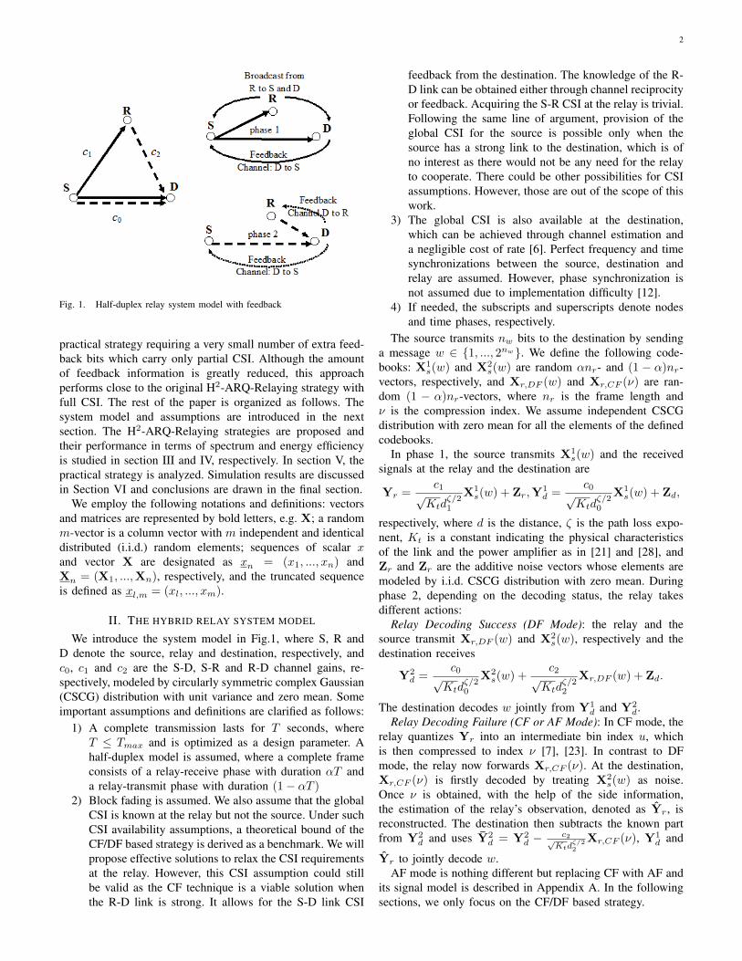
Fig. 1. Half-duplex relay system model with feedback
practical strategy requiring a very small number of extra feed-back bits which carry only partial CSI. Although the amountof feedback information is greatly reduced, this approachperforms close to the original H2-ARQ-Relaying strategy withfull CSI. The rest of the paper is organized as follows. Thesystem model and assumptions are introduced in the nextsection. The H2-ARQ-Relaying strategies are proposed andtheir performance in terms of spectrum and energy efficiencyis studied in section III and IV, respectively. In section V, thepractical strategy is analyzed. Simulation results are discussedin Section VI and conclusions are drawn in the final section.
We employ the following notations and definitions: vectorsand matrices are represented by bold letters, e.g. X; a randomm-vector is a column vector with m independent and identicaldistributed (i.i.d.) random elements; sequences of scalar xand vector X are designated as xn = (x1, ..., xn) andXn = (X1, ...,Xn), respectively, and the truncated sequenceis defined as xl,m = (xl, ..., xm).
II. THE HYBRID RELAY SYSTEM MODEL
We introduce the system model in Fig.1, where S, R andD denote the source, relay and destination, respectively, andc0, c1 and c2 are the S-D, S-R and R-D channel gains, re-spectively, modeled by circularly symmetric complex Gaussian(CSCG) distribution with unit variance and zero mean. Someimportant assumptions and definitions are clarified as follows:
1) A complete transmission lasts for T seconds, whereT ≤ Tmax and is optimized as a design parameter. Ahalf-duplex model is assumed, where a complete frameconsists of a relay-receive phase with duration αT anda relay-transmit phase with duration (1− αT )
2) Block fading is assumed. We also assume that the globalCSI is known at the relay but not the source. Under suchCSI availability assumptions, a theoretical bound of theCF/DF based strategy is derived as a benchmark. We willpropose effective solutions to relax the CSI requirementsat the relay. However, this CSI assumption could stillbe valid as the CF technique is a viable solution whenthe R-D link is strong. It allows for the S-D link CSI
feedback from the destination. The knowledge of the R-D link can be obtained either through channel reciprocityor feedback. Acquiring the S-R CSI at the relay is trivial.Following the same line of argument, provision of theglobal CSI for the source is possible only when thesource has a strong link to the destination, which is ofno interest as there would not be any need for the relayto cooperate. There could be other possibilities for CSIassumptions. However, those are out of the scope of thiswork.
3) The global CSI is also available at the destination,which can be achieved through channel estimation anda negligible cost of rate [6]. Perfect frequency and timesynchronizations between the source, destination andrelay are assumed. However, phase synchronization isnot assumed due to implementation difficulty [12].
4) If needed, the subscripts and superscripts denote nodesand time phases, respectively.
The source transmits nw bits to the destination by sendinga message w ∈ {1, ..., 2nw}. We define the following code-books: X1
s(w) and X2s(w) are random αnr- and (1 − α)nr-
vectors, respectively, and Xr,DF (w) and Xr,CF (ν) are ran-dom (1 − α)nr-vectors, where nr is the frame length andν is the compression index. We assume independent CSCGdistribution with zero mean for all the elements of the definedcodebooks.
In phase 1, the source transmits X1s(w) and the received
signals at the relay and the destination are
Yr =c1
√Ktd
ζ/21
X1s(w) + Zr,Y
1d =
c0√Ktd
ζ/20
X1s(w) + Zd,
respectively, where d is the distance, ζ is the path loss expo-nent, Kt is a constant indicating the physical characteristicsof the link and the power amplifier as in [21] and [28], andZr and Zr are the additive noise vectors whose elements aremodeled by i.i.d. CSCG distribution with zero mean. Duringphase 2, depending on the decoding status, the relay takesdifferent actions:
Relay Decoding Success (DF Mode): the relay and thesource transmit Xr,DF (w) and X2
s(w), respectively and thedestination receives
Y2d =
c0√Ktd
ζ/20
X2s(w) +
c2√Ktd
ζ/22
Xr,DF (w) + Zd.
The destination decodes w jointly from Y1d and Y2
d.Relay Decoding Failure (CF or AF Mode): In CF mode, the
relay quantizes Yr into an intermediate bin index u, whichis then compressed to index ν [7], [23]. In contrast to DFmode, the relay now forwards Xr,CF (ν). At the destination,Xr,CF (ν) is firstly decoded by treating X2
s(w) as noise.Once ν is obtained, with the help of the side information,the estimation of the relay’s observation, denoted as Yr, isreconstructed. The destination then subtracts the known partfrom Y2
d and uses Y2d = Y2
d −c2√
Ktdζ/22
Xr,CF (ν), Y1d and
Yr to jointly decode w.AF mode is nothing different but replacing CF with AF and
its signal model is described in Appendix A. In the followingsections, we only focus on the CF/DF based strategy.

3
Fig. 2. H2-ARQ-Relaying Strategy (4 frame categories defined)
III. A CF/DF BASED H2-ARQ-RELAYING STRATEGY
When retransmission protocols are considered, we canexpand the defined codebooks to X1
s,n(w), X2s,n(w),
Xr,DF,n(w) and Xr,CF,n(νn), for 1 ≤ n ≤ N , where N isthe maximum retransmission limit. As depicted in Fig.1, thefeedback channels are used to convey the decoding status atthe relay and the destination. During phase 1 of the n-th frame,the source broadcasts X1
s,n(w). If the message is successfullydecoded by the destination, where the decoding is based on allbuffered signals, an acknowledgement (ACK) message is sentback to the source and the relay and the transmission of w isfinished. If the destination detects errors, it broadcasts a notacknowledgement (NAK) message. Once the relay receives theNAK message, it tries to decode through a joint processing ofYrn
. Different actions are envisaged based on its decodingstatus:
Relay Decoding Success: An ACK is broadcast by the relayto indicate that it is working in DF mode. The relay andthe source transmit Xr,DF,n(w) and X2
s,n(w), respectively.Afterwards, the source keeps silent during phase 1 of thefollowing frames to save the energy. It only transmits withthe relay in a more efficient cooperative manner during phase2 until the source receives ACK or the retransmission limit Nis reached.
Relay Decoding Failure: The relay switches to CF modeand broadcasts a NAK message. At the end of phase 2, thedestination attempts to decode by joint processing Y1
dn, Yrn
and Y2dn
. Upon successful decoding, an ACK is sent back;otherwise, the destination issues a NAK message to start anew frame if n ≤ N . If n = N , HARQ failure is announced.
Fig.2 sketches all the possible scenarios. In the first one,w is successfully decoded during phase 1 of the K-th frameafter (K − 1) CF operations, in case 2, successful decodingoccurs after exact M CF operations, and in case 3, DF mode
TABLE IFRAME CATEGORIES
Category Name Definition
1 CoF(C) Complete Frames consisting of two phases,operating in CF mode in phase 2
2 BrF Broadcasting Frames consisting of phase 1 only3 CoF(D) Complete Frames consisting of two phases,
operating in DF mode in phase 24 RtF(D) Relay-transmit Frames consisting of phase 2
only, operating in DF mode5 CoF(A) Complete Frames consisting of two phases,
operating in AF mode in phase 26 CoF(Di) Complete Frame consisting of two phases
with direct transmission mode in both phases
is activated in the L-th frame but the destination does notcorrectly decode w until the K-th frame. Fig.2 also depicts twoscenarios where HARQ failure is announced when the relayworks in CF or DF mode, respectively. Accordingly, 4 framecategories are defined in Fig.2. Table I gives the definitionof frame categories. Here we assume that frames are spacedenough along the time domain or the frequency domain toensure independency of channel gains.
A state diagram is presented in Fig.3. Bn stands for the statewhere the source is ready to broadcast w in the n-th frame.The state Dn indicates that DF mode is activated at the endof phase 1 of the n-th frame. DFm,n is the state where thesystem has entered DF mode in the n-th frame and cooperativetransmission in phase 2 has been repeated m times but thedestination still detects errors. Cn defines the state in whichthe relay is ready to conduct CF during phase 2 of the n-thframe. S and Fa are the successful decoding state and HARQfailure state, respectively.

4
Fig. 3. State Diagram of the CF/DF based H2-ARQ-Relaying Strategy
IV. H2-ARQ-RELAYING PERFORMANCE ANALYSIS
In order to investigate the spectrum and energy efficiency ofthe H2-ARQ-Relaying strategies, the outage probability needsto be derived. Now we assume delay- and error-free feedbacklinks for the feedback information.
A. Outage Analysis
For the CF/DF based strategy, only the first 4 frame cate-gories in Table I are valid. We define the valid frame categoryset as J = {1, 2, 3, 4}. The achievable rates (ARs) in differentframe categories are different and derived in Appendix B. LetR(t) denote the AR at the destination in a category t frame,where t ∈ J , after n frames the AR can be expressed as
Rd(n) =
n∑i=1
R(ti), (1)
where ti is the category attribute of the i-th frame. Definetn = (t1, ..., tn) as the frame category indication sequence
(fcis). We also define υt(tm,n)def=
n∑i=m
1{ti=t} to indicate the
total number of category t frames from frame m to n, where1{ti=t} is an indication function whose value is 1 when ti = tand 0 otherwise. The AR at the relay after k transmissions isgiven as
Rr(k) =
k∑i=1
Rr,i =
k∑i=1
αB log2
(1 +
γ1,iE1b,snw
αTN0BKtdζ1
),
(2)where E1
b,s is the energy per bit at the source during phase 1,γj,i = |cj,i|2 for 0 ≤ j ≤ 2, B is the bandwidth, and N0 isnoise power.
If nw bits are transmitted in one frame, we can definethe event A(υ, k)
def= {Rd(n) ≤ nw/T,Rr(k) ≤ nw/T},
and the outage probability q (υ, k) = Pr (A(υ, k)), where
υ(tn) = (υ1, υ2, υ3, υ4) with υt = υt(tn) and n =4∑t=1
υt.
It is straightforward to show that under the block fadingassumption, for any fcis pair tn and t′n, the outage probabilitiesare the same as long as υ(tn) = υ(t′n). The outage probability
q(υ, k) can be calculated by resorting to the 2-dimensionalcharacteristic function of Rd(n) and Rr(k),
Ψ(s, n, k)=E{e−s1Rd(n)−s2Rr(k)
}=E
{k∏i=1
e−s1R(ti)−s2Rr,i
n∏i=k+1
e−s1R(ti)
}=∏t∈J{φt(s)}υt(tk)
∏t∈J
{φt(s1)
}υt(tk+1,n),
(3)
where s is (s1 s2), and
φt(s) = E{e−s1R
(t)−s2Rr}, φt(s1) = E
{e−s1R
(t)}.
The outage probabilities can be expressed by the Laplaceinversion formula of Ψ(s, n, k) and approximated in [26],
q(υ, k)=1
(2πj)2
d2+j∞∫d2−j∞
d1+j∞∫d1−j∞
Ψ(s, n, k)es1nwT +
s2nwT
s1s2ds1ds2
≈M∑i=1
M∑j=1
KiKjΨ(z, n, k)
zizj,
(4)
where d1 and d2 are proper constants, zi are the poles ofthe Pade rational function, z is (ziT/nw zjT/nw), Ki arethe corresponding residues and M is an arbitrary integerthat determines the approximation accuracy and is chosen as10 in this paper. The closed-form expressions of φt(z) andφt(ziT/nw) are difficult to obtain but we can resort to three-dimensional numerical integration. For instance
φt(ziT/nw) =
∫∫∫R+
e(−ziR(t)T/nw)p(γ)dγ0dγ1dγ2, (5)
where γ = (γ0, γ1, γ2), and p(γ) is the joint distribution ofγ0 to γ2.
AF/DF based H2-ARQ-Relaying: The above approximationcan be easily extended to the AF/DF based strategy. Thecorresponding valid frame category set is J = {2, 3, 4, 5},where in frame category 5, CF is replaced by AF. The AR atthe destination in AF mode is derived in Appendix A.
B. State and Transition Probabilities
For two event sets e1 and e2, if (e1 ⊆ e2), Pr(e1, e2) isequal to Pr(e1). In the state diagram, the transition probabilityto state j from any of its adjacent incoming state i is
Pr (state i→ state j)=Pr (state j|state i)
=Pr (state j)
Pr (state i).
(6)
In the state diagram shown in Fig.3, all the states havethis property except the state S. Therefore we can firstlycalculate the state probabilities and then obtain the transitionprobabilities based on (6).
We start from Bn and initialize Pr(B1) = 1. Pr(Bn) canbe easily obtained as q ((n− 1, 0, 0, 0) , n− 1). It follows that
5
Pr(Fa) is q ((N, 0, 0, 0), N). When the relay detects errors atthe end of phase 1 of the n-th frame, the state probability isPr(Cn) = q ((n− 1, 1, 0, 0), n); otherwise, the system movesto state Dn and the corresponding probability is given by
Pr(Dn)=Pr (A ((n− 1, 1, 0, 0) , n− 1))
−Pr (A ((n− 1, 1, 0, 0) , n))
=q ((n− 1, 1, 0, 0), n− 1)− q ((n− 1, 1, 0, 0), n) .
When the system is in the state DFm,n, it implies that (n+m−1) frames consisting of (n−1) CoF(C), 1 CoF(D) and (m−1)RtF(D) have been transmitted. Therefore, the probability is
Pr(DFm,n) = q ((n− 1, 0, 1,m− 1), n− 1)
−q ((n− 1, 0, 1,m− 1), n) .
There are three routes stemming from Bn. As the probabilitiesof all the state transitions emanating from a single state mustadd up to 1, we have Pr(Bn → S) = 1 − Pr(Bn → Dn) −Pr(Bn → Cn). Pr(Cn → S) and Pr(DFm,n → S) can beobtained in the same way.
C. Spectrum Efficiency Analysis
We analyze the spectrum efficiency in terms of the through-put. Using the state and transition probabilities, we can applythe renewal-reward theorem [23] to evaluate the throughputby investigating the random reward Φ and average airtime T .We first investigate the successful decoding events depicted inFig.2. T1 stands for the average time associated with case 1in Fig.2 and is given by
T1 = T
N∑K=1
PBS(K) ((K − 1) + α) ,
PBS(K) = Pr(BK)Pr(BK → S).
For case 2, where the system is able to decode after M CFoperations, the average time associated is
T2 = T
N∑M=1
PCS(M)M,PCS(M) = Pr(CM )Pr(CM → S).
The associated average time of case 3 is
T3 = T
N∑L=1
N∑K=L
PDS(L,K) (L+ (K − L)(1− α)) ,
PDS(L,K) = pDS(L,K),
where pDS (L,K) = Pr(DL)Pr(DL → S) when K = L andis equal to Pr(DF(K−L),L)Pr(DF(K−L),L → S) for K > L.
In the above cases, the decoding is successful and theaverage reward Φ is the number of successfully transmittedbits nw. When outage events happen, Φ is equal to zero. Theoutage events may happen in CF mode in case 4 and theaverage time is T4 = TPr(Fa)N . In contrast, if the outageevents occur in DF mode, the average time is given by
T5 = T
N∑L=1
P outDF (L)(L+ (N − L)(1− α)),
P outDF (L) = Pr(DFN−L+1,L).
Since the outage events in DF and CF modes are mutu-ally exclusive, the outage probability is pout = Pr(Fa) +N∑L=1
P outDF (L). The average random reward and the average
airtime take the forms of E {Φ} = nw (1− pout) and E {T } =5∑i=1
Ti. The average throughput is
µ(α, T ) =E{Φ}E{T }
=nw(1− pout)
5∑i=1
Ti
. (7)
The resulted throughput is a function of the duplexing ratio αand the activation time T . Therefore it should be maximizedwith respect to α and T as
µmax = maxT,α
µ(T, α). (8)
D. Energy Efficiency Analysis
Denote the transmission energy per bit at the source duringphase 1, 2, and at the relay as E1
b,s, E2b,s and Eb,r, respectively.
In phase 1, one node transmits and two nodes receive, theconsumed energy is
E1 = nwE1b,s + (Pct + 2Pcr)αT,
where Pct and Pcr are transmission and reception circuitrypower, respectively. During phase 2, if the relay decodesthe message, the relay intends to transmit nw bits and theconsumed energy is
E2DF = nwE
2b,s + nwEb,r + (2Pct + Pcr) (1− α)T.
If not, the consumed energy is
E2CF = nwE
2b,s + sEb,r + (2Pct + Pcr) (1− α)T,
where s is the number of bits required to transmit the com-pressed signal. Since s is a variable depending on the CSIof three links, if Eb,r is fixed, the relay transmitting powerPr =
sEb,r(1−α)T varies from frame to frame. In this work we
assume that Pr is fixed and thus Eb,r is adjusted by the relay ineach frame. It is more suitable to evaluate Pr instead of Eb,r inCF mode. For simplicity, we let the transmitting power of thesource be the same during two phases, i.e.
nwE1b,s
αT =nwE
2b,s
(1−α)T ,the overall energy consumptions per bit are
Eb,DF =E1b,s
α+ Eb,r +
(Pct + 2Pcr)αT
nw
+(2Pct + Pcr)(1− α)T
nw,
Eb,CF =E1b,s
α+
(Pct + 2Pcr + Pr)αT
nw
+(2Pct + Pcr)(1− α)T
nw,
respectively. We can take similar steps in the analysis ofaverage airtime T and calculate the average consumed energyper bit in five different cases in Appendix C. The average
energy per bit is ε(T,Eb,r, E1b,s) =
5∑i=1
Eb,i. The optimization
6
TABLE IIINDICATION BITS bn
bn γ regions
00 γ0,n ∈ (0, a2), γ2,n ∈ [a1,+∞)
01 γ0,n ∈ (0, a3), γ2,n ∈ (0, a1)
10 γ0,n ∈ [a2, a3], γ2,n ∈ [a1,+∞)
11 γ0,n ∈ [a3,+∞)
of ε(T,Eb,r, E1b,s) must be subject to some constraints. Here
we use the outage probability as the constraint and thisoptimization problem can be formulated as
min ε(T,Eb,r, E1b,s)
subject to pout ≤ pt, and T ≤ Tmax,(9)
where pt is the target outage probability. The dependencebetween pout and T , Eb,r and E1
b,s has been shown inAppendix B in the AR expressions. This optimization problemcan be solved numerically.
V. A MODIFIED STRATEGY WITH LIMITED CSI FEEDBACK
In this section, we focus on the practical issues and pro-pose a modified H2-ARQ-Relaying strategy with partial CSIfeedback. The basic idea of this strategy is to separate the two-dimensional space (γ0, γ2) into different operational regions,where different relaying schemes are carried out.
A. Strategy Description
Inspired by the idea in [6], we use two indication bitsbn = (b1,n b2,n) to designate the operational regions as shownin Table II. These two indication bits should be sent back fromthe destination to the relay and the source when CF mode isactivated and different operations are performed accordinglyduring phase 2. If the S-D link is above some threshold,i.e.,a3 ≤ γ0,n(bn = 11), we carefully choose a3 such that
nwT
= αB log2
(1 + a3
nwE1b,s
αTN0BKtdζ0
)
+(1− α)B log2
(1 + a3
nwE2b,s
(1− α)TN0BKtdζ0
),
and successful decoding is guaranteed at the destination evenwithout resorting to the buffered signals. In such a case, thereis no need for the relay to cooperate and it is silent duringphase 2. If γ0,n ∈ [a2, a3] and γ2,n ∈ [a1,+∞)(bn = 10),the relay performs CF. As a direct consequence of Corollary1 of [6], the AR at the destination in this non-ideal sce-nario is derived in Appendix B. When γ0,n ∈ (0, a2) andγ2,n ∈ [a1,+∞)(bn = 00), the ’amount’ of side informationis insufficient for efficient CF [6]. If γ0,n ∈ (0, a3) andγ2,n ∈ (0, a1)(bn = 01), the quality of the R-D link is toolow to support efficient transmission of the compressed signal.In either case, the relay cannot help and is kept silent. Sincethe direct link is of low quality now, to save the energy, thesource is switched off in phase 2 of the current frame. In this
Fig. 4. State transition diagram of the modified H2-ARQ-Relaying strategy(N=3, Gn,n1 : the combination state; Din,n1 : the direct transmission state)
frame the source only broadcasts in phase 1, thus we call itbroadcasting mode.
The state diagram of the modified strategy is shown in Fig.4.Bn,n1 is defined as the state where the destination has not beenable to decode after (n − 1) frames. It also implies that inn1 frames, CF is conducted and in the rest of the frames, thesystem works in broadcasting mode. When the system is in thestate Bn,n1
, upon successful decoding at the relay, the systemis ready to work in DF mode and transits to Dn,n1 . Afterwards,when category 4 frames are repeated for m times and thedestination still detects errors, the system reaches DFm,n,n1
.If the relay detects errors, with bn = 10, the system transits toCn,n1
and performs CF; with bn = 11, the relay knows thatthe direct link is strong, therefore it keeps silent during phase2 and the system enters a new state Din,n1 ; for the rest of thecases, the system transits to Bn+1,n1 directly. In order to keepFig.4 concise, we use a combination state Gn,n1
to indicate theDF operation. It should be noted that the direct transmissionis guaranteed to be successful by carefully selecting a3.
B. Outage Analysis
The fcis of the modified strategy has two properties:1) Each tn can be segmented into two sub-sequences tn =
(tκ, tκ+1,n). From frame 1 to κ, the system works in CFor broadcasting mode and tκ is a sequence composed of 1and 2; from the (κ+1)-th frame, the system works in DFor direct transmission mode, thus tκ+1,n is formed with3, 4 and 6. We have κ = υ1 + υ2, n− κ = υ3 + υ4 + υ6
and obviously υ1(tκ) = υ1(tn).2) For each υ1(tn), there are Cκυ1
=(κυ1
)possible
sub-sequences tκ forming a set Fυ . However, onceυ3(tκ+1,n),υ4(tκ+1,n) and υ6(tκ+1,n) are known, thecorresponding sub-sequence tκ+1,n is unique becauseaccording to the strategy description, it can only takethe forms of sequence (3), (6) or (3, 4, 4, ..., 4).

7
Now we rewrite the outage probability as an explicit func-tion of tn: q(tn, k) = Pr(Rd(n) < nw/T,Rr(k) < nw/T, tn)and define υ = (υ1, υ2, υ3, υ4, υ6). Under the block fadingassumption, it is straight forward to come to the conclusionthat if υ(tn) = υ(t′n), we still have q(tn, k) = q(t′n, k). Itmeans that for any particular υ, each fcis in Fυ has the sameoutage probability. Thus without loss of generality, we assumethat for any tn, the first sub-sequence after segmentation takesthe form as tPκ (υ1) = (11, 11, ..., 1υ1 , 2υ1+1, 2υ1+2, ..., 2κ) forsimplicity. Then the outage probability is
q(tn, k) = q((tPκ (υ1), tκ+1,n), k
)= Pr
(Rd(n) <
nwT,Rr(k) <
nwT,(tPκ (υ1), tκ+1,n
)).
The overall outage probability associated with set Fυ can beexpressed as
Pr(Fυ) = Cκυ1q((tPκ (υ1), tκ+1,n
), k).
Unfortunately, this outage probability cannot be approximatedin the same way described in the previous section due tothe explicit argument tPκ (υ1), which introduces κ additionalconditions and this fact violates the applicable condition ofthe 2-dimensional characteristic function.
C. State and Transition Probabilities
The state probabilities of the modified strategy can beobtained in a similar way. Pr(B1,0) is initialized to 1 andthe state probability of Bn,n1 can be expressed as
Pr(Bn,n1) = Cn−1
n1q(tPn−1(n1), n− 1).
In the state Bn,n1, the source broadcasts. If only the relay
successfully decodes the message, the system moves to Dn,n1
and its state probability is
Pr(Dn,n1) = Cn−1
n1
(q(tPn (n1), n− 1)− q(tPn (n1), n)
).
Similarly, the state probability of Cn,n1is
Pr(Cn,n1) = Cn−1
n1q(tPn−1(n1), n,bn),
where we make bn explicit to indicate the operational regions.The rest of the state probabilities can be given as
Pr(DFm,n,n1) = Cn−1n1
(q((tPn−1(n1), 3, 41, ..., 4m−1
), n− 1
)−q((tPn−1(n1), 3, 41, ..., 4m−1
), n)),
and Pr(Din,n1) = q
((tPn−1(n1), 6), n− 1
).
D. Throughput and Energy Analysis
To evaluate the average airtime, we investigate the timeconsumed when the system reaches a certain state. Definee(l,m)
def= m + (l − m)α. T1(K,n1) is the average time
associated with case 1 of the original strategy, where thedestination decodes in phase 1 of the K-th frame. However,it differs in that it also depends on n1 and is given as:
G1(K,n1) = TP (BK,n1)P (BK,n1
→ S) (e(K − 1, n1) + α) .
When all possible K and n1 are taken into consideration, theoverall average time is
T1 =
N∑K=1
K−1∑n1=0
G1(K,n1).
The consumed energy is then given as
Eb,1 =
N∑K=1
K−1∑n1=0
P (BK,n1)P (BK,n1
→ S)
(n1Eb,CF
+(K − n1)E1
nw
).
By averaging with respect to n1 as well, the average airtimeand energy in the rest of the cases can be obtained in a similar
way except T4 = TN∑
n1=0P (BN+1,n1
)e(N,n1) , which is
the average airtime when HARQ failure is announced in CFor broadcasting mode. In addition, we also need to consideranother case where the system ends up in direct transmissionmode during the M -th frame. We have
T6 =
N∑M=1
M−1∑n1=0
G6(M,n1)
G6(M,n1) = TPr(DiM,n1)Pr(DiM,n1 → S)e(M,n1).
The consumed energy is
Eb,6 =
N∑M=1
M−1∑n1=0
Pr(DiM,n1)Pr(DiM,n1 → S)
·(n1Eb,CF +
(M − n1 − 1)E1
nw+ Eb,CF −
Pct(1− α)T
nw
).
where the last two terms represent the energy per bitof the direct transmission. The average energy per bit is
ε(T,Eb,r, E
1b,s
)=
6∑i=1
Eb,i, which is a similar optimization
problem as (9). The resulted average throughput is a functionof the duplexing ratio α, the activation time T and theparameters a1, a2 and a3. Therefore the average throughputcan be maximized as
µmax = maxT,α,a1,a2,a3
E{Φ}E{T }
=nw(1− pout)
6∑i=1
Ti
. (10)
where
pout =
N∑n1=0
Pr(BN+1,n1) +
N∑L=1
L−1∑n1=0
Pr(DFN−L+1,L,n1).
VI. NUMERICAL RESULTS, COMPARISONS ANDDISCUSSIONS
In this section, we provide some results for the proposedstrategies and compare their performance with some bench-mark ones:
1) H-ARQ with direct transmission (DT): The relay keepssilent throughout the transmission.
8
Fig. 5. ρD , ρA and ρC for optimal and fixed α. (e=1.2, b/r = e/6, N = 4)
2) H-ARQ-Relaying with the co-located relay and destina-tion (CRD): We assume that the relay and the destinationare connected by a wire such that full receive diversityis achieved.
3) H-ARQ-Relaying with conventional DF (DF U): Whenthe relay detects errors, it keeps silent during phase 2;otherwise, the relay and the source transmit simultane-ously.
4) H-ARQ-Relaying with simple multi-hop strategy (DF-sms): There is no direct link between the source and thedestination. During phase 1, the source transmits to therelay and only the relay receives and decodes. Duringphase 2, the source keeps silent. If the relay detectserrors, it is silent; otherwise, the relay transmits to thedestination. Here α is set at 0.5.
5) H2-ARQ-Relaying with hybrid AF/DF (HAD): The re-lay performs AF when detecting errors and DF whensuccessfully decoding. Note that in this case, α is alsofixed at 0.5 and repetition coding is used when AF isperformed.
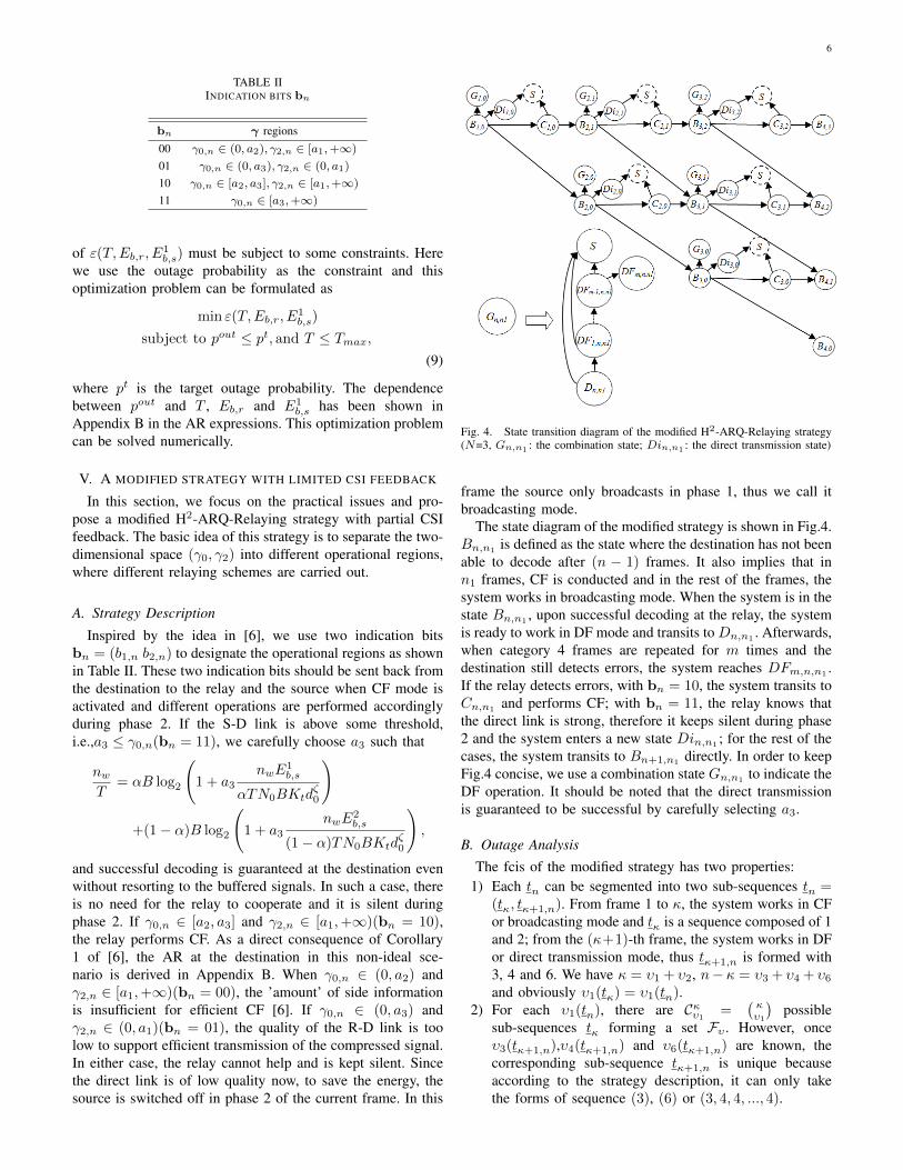
The maximum retransmission limit N is set to 4. TheCF/DF based strategy and its modified version are denotedas HCD and MHS, respectively. The analytical derivations ofthe previous sections are verified through appropriate MonteCarlo simulations and close match was observed for allthe possible range of SNRs as shown in Fig.6. To avoidcrowded figures, we only present the Monte Carlo results forHCD to show the match (here the two curves are actuallyoverlapping). For the rest of the strategies, only analyticalresults are illustrated. We use the following settings: nw = 10,Pct = 98mW , Pcr = 112.4mW , Kt = 6.05 × 10⁹, ζ = 3,N0 = −171dBm/Hz, B = 1 and Tmax = 1. The distancebetween the source and the destination is r. The source andthe destination are assumed to be placed in the foci of theellipse (d/r)2/(e/2)2 +(y/r)2/(b/r)2 = 1, for 1 < e < +∞,and the relay is moving along the upper side of the ellips.
Fig. 6. Throughput µmax with the ellipse model (e = 1.2, b/r = e/6,Monte-Carlo means that the curve is obtained through Monte-Carlo simula-tion))
A. Adaptation Ability
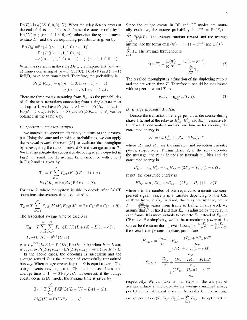
Here we assume that r = 100m, the transmit power of thesource and the relay is the same and normalized so that theaverage SNR of the S-D link is 0dB (change of this valuemight change the absolute values of our results but the trendswill not be affected). In order to investigate the dynamics ofthe hybrid systems, we define ρD and ρC as the percentages ofDF and CF operation time in the overall airtime, respectively,and their expressions are described in Appendix C. These twoparameters depend on two factors: the average number of DFor CF operations and the duration of phase 2. We show ρDand ρC of different strategies in Fig.5. In addition, we plot thedecoding probability of the relay node when n = 1 and 4. Itis shown that when the relay is moving towards the source (ddecreases), the relay’s decoding probability increases. Hence,the system is more likely to operate in DF mode and theduration of phase 2 becomes longer, leading to increased ρD.While d increases, the relay’s decoding probability decreasesand the average number of CF operations increases, whichtends to increase ρC . However, the duration of the secondphase tends to be shortened, which decreases ρC . ThereforeρC is not monotonically changing with d. Only when α isfixed, ρC is a non-decreasing function of d. For the AF/DFH2-ARQ-Relaying strategy, ρA can be obtained in a similarmanner and the same claims stand.
B. Comparisons of Spectrum Efficiency
Fig.6 depicts the throughputs of strategies with respect tod/r. For the modified strategy we resorted to the Monte-Carlosimulations. Basically, the throughputs are upper bounded byCRD because it is able to enjoy full receive diversity. TheCF/DF based strategy is the closest one to CRD. It can beinterpreted as follows: when the relay is moving towardsthe destination, the S-R link is getting less reliable and thesuccessful decoding probability at the relay decreases. In such

9
Fig. 7. Energy Efficiency in the short range (Joule per bit)
a scenario, if the system uses DF, it is more likely thatthe relay’s decoding fails and the system operates in directtransmission mode during phase 2, thus no diversity can beachieved. In contrast, when the hybrid CF/DF scheme is used,the system is able to achieve receive diversity through CF. Asfar as HAD is concerned, it enjoys a certain level of flexibilityand its throughput is improved in comparison with DF Uwhen α is fixed at 0.5. However, when the S-R link is of lowquality, the relay forwards nothing but mostly its own noise.In addition, HAD suffers from the bandwidth loss due to theuse of repetition coding, and its throughput is therefore lowerthan DF U with optimal α. Among all the relaying strategiesDFsms has the worst performance because without the directS-D link, when the relay is either too close to the sourceor the destination, there must be a very weak link betweenthe S-R and the R-D links and this weak link dominatesand degrades the performance. Another common trend (exceptDFsms) is that when the relay moves away from the source,their throughputs decrease. For DF U, this can be explainedby the smaller decoding probability of the relay, which causesfewer opportunities for the relay to cooperate. For HCD,although CF can be used, the achievable rate depends on thequality of the S-D and S-R links as shown in (14). The averageSNR of the S-R link is decreasing when the relay movestowards the destination. Hence, the throughput reduces. TheAF/DF based strategies can be explained following the sameline of argument.
C. Comparisons of Energy Efficiency
We optimize the energy per bit for both the source andthe relay and compare the energy efficiency performance ofvarious strategies when the relay is close to the destination (theS-D link and R-D link are vertical to each other). Fig.7 showsthe situation where the S-D distance is short (r < 100m).The direct transmission is more efficient than any of thecooperative strategies in terms of the energy per bit in shortrange. This is because now the circuitry energy consumptionis the major part of the overall energy consumption. If therelay is activated, although the transmission energy per bit
Fig. 8. Energy Efficiency in the long range (Joule per bit)
can be reduced, the overall circuitry consumption is almostdoubled. Thus, to optimize the energy consumption, the relayshould be switched off to save energy. The DF based strategyconsumes less energy than others because in this strategy, therelay is silent when detecting errors and the circuitry energyconsumption is saved, while in the hybrid strategies, the relaystill transmits, leading to extra circuitry energy consumption.When the S-D distance is increased (r > 100m) in Fig.8,circuitry energy consumption becomes minor and the relay isable to help to reduce the overall energy per bit. The CF/DFbased strategy has the best energy efficiency performance.Compared with the DF based one, the energy per bit isreduced by around 20% when r = 1000m for a target outageprobability 10−2. However, this savings is under the constraintthat full CSI feedback to the relay requires negligible amountof energy. When partial CSI case is considered, in smalltransmission range scenario the energy per bit of the MHSstrategy is slightly better than that of HCD. The reason is thatbased on the partial CSI feedback, the MHS strategy is able toshut down both the source and the relay during phase 2 whenthe channel quality is very low to save energy, especially thecircuitry energy. In the long range case, MHS strategy performsclose to the perfect CSI case. Another interesting observationis that, without the direct S-D link, the energy consumptionof DFsms is even higher than direct transmission. This canbe easily understood: now the relay is close to the destinationand the S-R link is weak. Thus DFsms suffers from significantloss in the AR. To achieve the target outage probability, thepower of the source and relay should be increased and theincreased energy consumption outweighs the savings of usingthe relay. It should be noted that the results in this work havebeen provided for a stringent target outage probability of 10−2,if the systems is allowed to operate at a lower outage levelaround 10−1, more energy savings can be expected.
VII. CONCLUSIONS AND FUTURE WORKS
In this paper, we developed novel H2-ARQ-Relaying strate-gies, where flexible approaches are taken to combine differentforwarding strategies, enabling the system to efficiently and
10
dynamically adapt itself to the variations of the channel. TheCF/DF based strategy shows significant improvement in termsof throughput and energy consumption. However, it shouldbe emphasized that compared with direct transmission, thecooperative strategy only shows improved energy efficiencywhen the distance between the destination and the source islarge. The main advantage of the proposed hybrid CF/DF orAF/DF based strategy is that it can achieve either transmit orreceive diversity. Moreover, since the global CSI is requiredat the relay for CF, an effective and practical method ofquantized CSI feedback is proposed. It imposes very smallfeedback overhead. The modified strategy is able to approachthe performance of the original one while keeping the CSIfeedback overhead below practically viable limits. Anotherissue we need to emphasize is the power model employed.For a meaningful analysis we need to strike the right balancebetween realistic modeling and mathematical tractability andwe believe that with current model the more important aspectsof realistic energy consumption are well captured. We will tryto use more complicated and realistic models in our futurework.
Generally speaking, in addition to the channel circumstancesdescribed in this paper, there are many other scenarios thatare worth investigating. Firstly, some practical limitationsdo apply. For instance, in case of DF based relaying, therelay needs to be aware of all necessary parameters that anintended receiver should know in order to decode the messagebefore forwarding it. Furthermore, the relay may need moreinformation regarding the second hop channel, in order todevise an energy and spectrum efficient forwarding strategy.However, in most of the practical system scenarios theserequirements can be met at the expense of increased signalingoverhead and the relaying schemes can still be used to improvethe overall system performance. Secondly, the feedback mightnot be error-free and this more realistic assumption will affectthe performance of the schemes. Finally, the relaying schemecan be more flexible by switching between more operationalmodes such as silent mode, AF, DF, CF and even quantize-and-forward [6] to achieve an optimal trade-off between thethroughput, complexity, energy consumption and signalingoverhead. It would be of great interest to examine these issuesin the future.
APPENDIX A
For the AF scheme, when the source is allowed to transmitduring phase 2, the received signal at the destination takes theform as Yd = CX1
s + BZ,where
Yd =(Y 1d Y 2
d
)T,Z =
(Z1r Zd Z
2r
)TC =
(c0
√Ktd
ζ/20
βrc1c2Kt(d1d2)ζ/2
+c0
√Ktd
ζ/20
)T
B =
(0 1 0
βrc2√Kt(d2)ζ/2
0 1
)and βr is the amplification function, subject to the power con-
straint βr ≤√Pr/
(γ1nwE1
b,s
αTKtdζ1
+N0B)
.Using vector results
in [27], the AR to the destination is
I(X1s ; Yd) = B log2 det
(I2 +
(CCH
)(BE
(ZZH
)BH)−1
),
where I2 is a 2-by-2 identity matrix and the covariance matrixE{
ZZH}
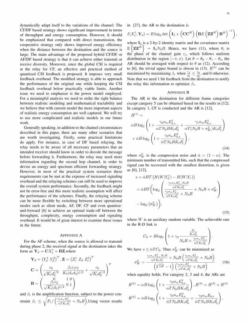
= I3N0B. Hence, we have (11), where θi isthe phase of the channel gain ci, which follows uniformdistribution in the region [−π, π). Let θ = θ0 − θ1 − θ2, theAR should be averaged with respect to θ as (12). Accordingto [6], the trivial upper bound is shwon in (13). R(5) can bemaximized by maximizing βr when γ1
dζ1≤ γ0
dζ0, and 0 otherwise.
Note that we need 1 bit feedback from the destination to notifythe relay this information to optimize βr.
APPENDIX BThe AR to the destination for different frame categories
except category 5 can be obtained based on the results in [12].In category 1, CF is conducted and the AR is [12],
R(1) =
αB log2
(1 +
γ0nwE1b,s
αTN0BKtdζ0
+γ1nwE
1b,s
αT (N0B + σ2W )Ktd
ζ1
)
+ αB log2
(1 +
γ0nwE2b,s
αTN0BKtdζ1
),
(14)
where σ2W is the compression noise and α = (1 − α). The
minimum number of transmitted bits, such that the compressedsignal can be recovered with the smallest distortion, is givenas [6], [12],
s = αBT(H(W |Y 1
d )−H(W |Yr))
= αBT
(log2
γ1nwE1b,sN0B
αTKtdζ1
γ0nwE1b,s
αTKtdζ0
+N0B+N0B + σ2
W
− log2
(σ2W
)),
(15)
where W is an auxiliary random variable. The achievable ratein the R-D link is
C0 = Blog2
1 + γ2
PrKtd
ζ2
N0B +γ0nwE2
b,s
αTKtdζ0
.
We have s ≤ αTC0. Thus σ2W can be minimized as
σ2W =
γ1nwE1b,sN0B
αTKtdζ1
+N0B(γ0nwE
1b,s
αTKtdζ0
+N0B)
(2αC0αB − 1
)(γ0nwE1
b,s
αTKtdζ0
+N0B) (16)
when equality holds. For category 2, 3 and 4, the ARs are
R(2) = αB log2
(1 +
γ0nwE1b,s
αTN0BKtdζ0
), R(3) = R(2) +R(4)
R(4) = αB log2
(1 +
γ0nwE2b,s
αTN0BKtdζ0
+γ2nwEb,r
αTN0BKtdζ2
),
11
I(X1s ; Yd) = B log2
1 +γ0Ps
N0BKtdζ0
+Ps|βrc1c2e
−j(θ0−θ1−θ2)
Kt(d1d2)ζ/2+ c0√
Ktdζ/20
|2
N0B(
1 +β2rγ2
Ktdζ2
) , (11)
RAF =1
2π
+π∫−π
I(X1s ; Yd)dθ = R(5) +B log2
1
2+
1
2
√√√√√√1−4β2rγ0γ1γ2
K3t (d1d2d3)ζ((
1 +γ0nwE1
b,s
αTN0NKtdζ0
)(1 +
β2rγ2
Ktdζ2
+β2rγ1γ2
K2t (d1d2)ζ
))2
, (12)
R(5) = B log2
1 +γ0nwE
1b,s
αTN0BKtdζ0
+nwE
1b,s
(β2rγ1γ2
K2t (d1d2)ζ
+ γ0
Ktdζ0
)αTN0B
(1 +
β2rγ2
Ktdζ2
) . (13)
respectively.
When the modified scheme is applied, the AR has the sameexpression as (14) by replacing σ2
w with σ2W . If γ0 and γ2
are in the region [a2, a3] and [a1,+∞) respectively, we cancarefully choose the transmission rate of the relay as
s
αT≤ s
αT≤ C0
C0 = B log2
1 + a1
PrKtd
ζ2
N0B +a3nwE2
b,s
αTKtdζ0
≤ C0,
where s can be calculated as (15) by replacing γ0 with a2. Tocalculate σ2
W , we can replace γ0 and C0 with a3 and C0 in(16).
APPENDIX C
The average consumed energy per bit in five different casesfor the hybrid schemes are
Eb,1 =
N∑M=1
PCS(M)MEb,CF ,
Eb,2 =
N∑K=1
PBS(K)
((K − 1)Eb,CF +
E1
nw
),
Eb,3 =
N∑L=1
N∑K=L
PDS(L,K)
·(
(L− 1)Eb,CF + Eb,DF + (K − L)E2DF
nw
),
Eb,4 = Pr(Fa)NEb,CF ,
Eb,5 =N∑L=1
P outDF (L)
((L− 1)Eb,CF + Eb,DF + (N − L)
E2DF
nw
),
Definition of ρD and ρC are
ρD=α
E {T }
( N∑K=1
((PBS (K) + Pr (DFN−K+1,K)) (K − 1)
+PCS(K)K)
+
N∑L=1
N∑K=L
PDS(L,K)(L− 1) + Pr(Fa)N
)
ρC=α
E {T }( N∑K=1
Pr(DFN−K+1,K)(N −K + 1)
+
N∑L=1
N∑K=L
PDS(L,K)(K − L+ 1))
ACKNOWLEDGMENT
The research leading to these results has received fundingfrom the European Community’s Seventh Framework Pro-gramme [FP7/2007-2013] under grant agreement no. 247733- project EARTH.
REFERENCES
[1] M. Janani, A. Hedayat, T. E. Hunter, and A. Nosratinia, “Codedcooperation in wireless communications: Space-time transmission anditerative decoding,” IEEE Trans. Signal Process.,vol. 52, no. 2, pp. 362-371, Feb. 2004.
[2] T. E. Hunter and A. Nosratinia, “Diversity through coded cooperation,”IEEE Trans. Wireless Commun., vol. 5, no. 2, pp. 283-289, Feb, 2006.
[3] J. N. Laneman, D. N. C. Tse and G. W. Wornell, “Cooperative diversityin wireless networks: Efficient protocols and outage behavior,” IEEETrans. Inform. Theory, vol. 50, no. 12, pp. 3062-3080, Dec. 2004.
[4] Z. Liu, V. Stankovic and Z. Xiong, “Wyner-Ziv coding for the half-duplex relay channel,” in Proc. IEEE Int. Conf. on ASSP, Philadelphia,PA, USA, Mar. 2005, pp. 1113-1116.
[5] R. Hu and J. Li, “Practical compress-forward in user cooperation:Wyner-Ziv cooperation,” in Proc. ISIT, Seattle, USA, Jul. 2006, pp. 489-493.
[6] M. Katz and S. Shamai, “Relay protocols for two co-located users,”IEEE Trans. Inform. Theory, vol. 52, no. 6, pp. 2329-2344, Jun. 2006.
[7] Z. Liu, S. Cheng, A. Liveris, and Z. Xiong, “Slepian-Wolf codednested lattice quantization for Wyner-Ziv coding: high-rate performanceanalysis and code design,” IEEE Trans. Inform. Theory, vol. 52, no. 10,pp. 4358-4379, Oct. 2006.
[8] M. Yuksel, and E. Erkip, “Multi-antenna cooperative wireless systems:A diversity-multiplexing tradeoff perspective,” IEEE Trans. Inform.Theory, vol. 53, no. 10, pp. 3371-3393, Oct. 2007.
[9] C. T. K. Ng and A. Goldsmith, “The Impact of CSI and power allocationon relay channel capacity and cooperation strategies,” IEEE Trans.Wireless Commun., vol. 7, no. 12, pp. 5380-5389, Dec. 2008.

12
[10] C. T. K. Ng, N. Jindal, A. Goldsmith, and U. Mitra, “Capacity gainfrom two-transmitter and two-receiver cooperation,” IEEE Trans. Inform.Theory, vol. 53, no. 10, pp. 3822-3827, Oct. 2007.
[11] P. Rost and G. Fettweis, “Analysis of a mixed strategy for multiple relaynetworks,” IEEE Trans. Inform. Theory, vol. 55, no. 1, pp. 174-189, Jan.2009.
[12] A. Host-Madsen and J. Zhang, “Capacity bounds and power allocationfor wireless relay channels,” IEEE Trans. Inform. Theory, vol. 51, no.6, pp. 2020 - 2040, Jun 2005.
[13] Y. Li, B. Vucetic, Z. Chen, and J. Yuan, “An improved relay selectionscheme with hybrid relaying protocols,” in Proc. IEEE GLOBECOM,New Orleans, USA, Nov. 2007, pp. 3704-3708.
[14] Y. Li, B. Vucetic, and J. Yuan, “Distributed turbo coding with hybridrelaying protocols,” in Proc. IEEE 19th Int. Symp. on Personal, Indoorand Mobile Radio Communications (PIMRC’08), Cannes, France, Sept.2008, pp. 1-6.
[15] S. Serbetli and A. Yener, “Power allocation and hybrid relaying strategiesfor F/TDMA Ad Hoc networks,” in Proc. IEEE Int. Conf. on Commu-nications (ICC’06), Istanbul, Turkey, Jun. 2006, pp. 1562-1567.
[16] L. L. Peterson and B. S. Davie, Computer Networks: A SystemsApproach, Third Edition, London, Academic Press, 2003.
[17] T. Tabet, S. Dusad, and R. Knopp, “Diversity-multiplexing-delay trade-off in half-duplex ARQ relay channels,” IEEE Trans. Inform. Theory,vol. 53, no. 10, pp. 3797 - 3805, Oct. 2007.
[18] L. Dai and K. Letaief, “Throughput maximization of ad-hoc wirelessnetworks using adaptive cooperative diversity and truncated ARQ,” IEEETrans. Commun., vol. 56, no. 11, pp. 1907-1918, Nov. 2008.
[19] B. Zhao and M. C. Valenti, “Practical relay networks: a generalizationof hybrid-ARQ,” IEEE J. Select. Areas Commun. (JSAC), vol. 23, no.1, pp. 7-18, Jan. 2005.
[20] R. Hoshyar, and R. Tafazolli, “Performance evaluation of HARQschemes for cooperative regenerative relaying,” in emphProc. IEEE Int.Conf. on Communications (ICC’09), Dresden, Germany, Jun. 2009, pp.1-6.
[21] I. Stanojev, O. Simeone, Y. Bar-Ness, and D. Kim, “Energy efficiency ofnon-collaborative and collaborative hybrid-ARQ protocols,” IEEE Trans.Wireless Commun., vol. 8, no. 1, pp. 326-335, Jan. 2009.
[22] K. Pang, Y. Li and B. Vucetic, “An improved hybrid ARQ scheme incooperative wireless networks,” in emphProc. 68th IEEE semiannualVehicular Technology Conf. (VTC’08-Spring), Singapore, Singapore,Sept. 2008, pp. 1-5.
[23] G. Caire and D. Tuninetti, “The throughput of hybrid-ARQ protocolsfor the Gaussian collision channel,” IEEE Trans. Inform. Theory, vol.47, no. 5, pp. 1971-1988, Jul. 2001.
[24] A. Wyner and J. Ziv, “The rate-distortion function for source codingwith side information at the decoder,” IEEE Trans. Inform. Theory, vol.22, no. 1, pp. 1-10, Jan. 1976.
[25] A. Wyner, “The rate-distortion function for source coding with sideinformation at the decoder-II: General sources,” Inform. Contr., vol. 38,pp. 60-80, Jul. 1978.
[26] K. Singhal, J. Vlach, and M. Vlach, “Numerical inversion of multidi-mensional Laplace transform,” in Proc. of the IEEE, vol. 63, no. 11, pp.1627 - 1628, Nov. 1975.
[27] I. E. Telatar, “Capacity of multi-antenna Gaussian channels,” EuropeTrans. Telecommun., vol. 10, pp. 585-596, Nov.-Dec. 1999.
[28] S. Cui, A. Goldsmith and A. Bahai, “Energy-Constrained ModulationOptimization”, IEEE Trans. Wireless Commun., vol. 4, no. 5, pp. 2349-2360, Sep. 2005.
Yinan Qi received the B.Sc degree in Electron-ics and Information Theory and the M.Sc degreein mobile communications from Peking University,Beijing, China, in 2000 and 2003, respectively, andthe Ph.D degree in Electronic Engineering fromUniversity of Surrey, Surrey, United Kingdom. From2003 to 2004, he has been a research scholar inNational University of Singapore. He is currentlya research fellow at the Centre for CommunicationSystems Research (CCSR) at the University of Sur-rey. His main research interests include cooperative
communications, coding, analysis and systematic modelling of future cellularsystems, and green communications.
Reza Hoshyar received his B.S. degree in commu-nications engineering and his M.S. and Ph.D. de-grees, both in mobile communications, from TehranUniversity, Tehran, Iran, in 1991, 1996, and 2001,respectively. He received the top and second rankawards for his B.S. and M.S. degrees from TehranUniversity. From 2002 to September 2010, he hasbeen a Research Fellow and then Senior ResearchFellow in the Mobile Communications ResearchGroup, Centre for Communication Systems Re-search (CCSR), University of Surrey, Surrey, United
Kingdom During this period, he was been actively involved in severalEuropean projects focusing on advanced digital signal processing, codingand modulation, and scheduling techniques for relaying, and cooperativecommunications in OFDM/OFDMA systems. Currently he is a system designengineer at National Semiconductor research lab, California, USA. His currentfocus is on power line communications and high-speed 60 GHz short rangewireless communication.
Muhammad Ali Imran (M’03) received his B.Sc.degree in Electrical Engineering from Universityof Engineering and Technology Lahore, Pakistan ,in 1999, and the M.Sc. and Ph.D. degrees fromImperial College London, UK, in 2002 and 2007,respectively. He secured first rank in his BSc anda distinction in his MSc degree along with anaward of excellence in recognition of his academicachievements confered by the President of Pakistan.He is currently a lecturer in the Centre for Commu-nication Systems Research (CCSR) at the University
of Surrey, UK. He has been actively involved in European Commission fundedresearch projects ROCKET and EARTH, Mobile VCE funded project onfundamental capacity limits and EPSRC funded project India UK ATC. Heis the principal investigator of EPSRC funded REDUCE project. His mainresearch interests include the analysis and modelling of the physical layer,optimisation for the energy efficient wireless communication networks andthe evaluation of the fundamental capacity limits of wireless networks.
Rahim Tafazolli (SM’09) is a professor and theDirector of Centre for Communication Systems Re-search (CCSR), University of Surrey, United King-dom. He has been active in research for more than 20years and has authored and co-authored more than360 papers in refereed international journals andconferences. Professor Tafazolli is a consultant tomany mobile companies, has lectured, chaired, andbeen invited as keynote speaker to a number of IEEand IEEE workshops and conferences. He has beenTechnical Advisor to many mobile companies, all in
the field of mobile communications. He is the Founder and past Chairmanof IEE International Conference on 3ed Generation Mobile Communications.He is Chairman of EU Expert Group on Mobile Platform (e-mobility SRA)and Chairman of Post-IP working group in e-mobility, past Chairman of WG3of WWRF. He is nationally and internationally known in the field of mobilecommunications.


![Ej Arq Soft200405[1]](https://static.fdokumen.com/doc/165x107/631a67acd5372c006e037ada/ej-arq-soft2004051.jpg)