Adaptive Distance Relaying Scheme for Transmission Network Connecting Wind Farms
14
This article was downloaded by: [Indian Institute of Technology - Delhi] On: 24 December 2014, At: 10:37 Publisher: Taylor & Francis Informa Ltd Registered in England and Wales Registered Number: 1072954 Registered office: Mortimer House, 37-41 Mortimer Street, London W1T 3JH, UK Click for updates Electric Power Components and Systems Publication details, including instructions for authors and subscription information: http://www.tandfonline.com/loi/uemp20 Adaptive Distance Relaying Scheme for Transmission Network Connecting Wind Farms Rahul K. Dubey a , Subhransu Ranjan Samantaray b & Bijay Ketan Panigrahi a a Department of Electrical Engineering, Indian Institute of Technology, Delhi, India b School of Electrical Science, Indian Institute of Technology, Bhubaneswar, India Published online: 30 Jul 2014. To cite this article: Rahul K. Dubey, Subhransu Ranjan Samantaray & Bijay Ketan Panigrahi (2014) Adaptive Distance Relaying Scheme for Transmission Network Connecting Wind Farms, Electric Power Components and Systems, 42:11, 1181-1193, DOI: 10.1080/15325008.2014.921953 To link to this article: http://dx.doi.org/10.1080/15325008.2014.921953 PLEASE SCROLL DOWN FOR ARTICLE Taylor & Francis makes every effort to ensure the accuracy of all the information (the “Content”) contained in the publications on our platform. However, Taylor & Francis, our agents, and our licensors make no representations or warranties whatsoever as to the accuracy, completeness, or suitability for any purpose of the Content. Any opinions and views expressed in this publication are the opinions and views of the authors, and are not the views of or endorsed by Taylor & Francis. The accuracy of the Content should not be relied upon and should be independently verified with primary sources of information. Taylor and Francis shall not be liable for any losses, actions, claims, proceedings, demands, costs, expenses, damages, and other liabilities whatsoever or howsoever caused arising directly or indirectly in connection with, in relation to or arising out of the use of the Content. This article may be used for research, teaching, and private study purposes. Any substantial or systematic reproduction, redistribution, reselling, loan, sub-licensing, systematic supply, or distribution in any form to anyone is expressly forbidden. Terms & Conditions of access and use can be found at http:// www.tandfonline.com/page/terms-and-conditions
-
Upload
independent -
Category
Documents
-
view
3 -
download
0
Transcript of Adaptive Distance Relaying Scheme for Transmission Network Connecting Wind Farms
This article was downloaded by: [Indian Institute of Technology - Delhi]On: 24 December 2014, At: 10:37Publisher: Taylor & FrancisInforma Ltd Registered in England and Wales Registered Number: 1072954 Registered office: Mortimer House,37-41 Mortimer Street, London W1T 3JH, UK
Click for updates
Electric Power Components and SystemsPublication details, including instructions for authors and subscription information:http://www.tandfonline.com/loi/uemp20
Adaptive Distance Relaying Scheme for TransmissionNetwork Connecting Wind FarmsRahul K. Dubeya, Subhransu Ranjan Samantarayb & Bijay Ketan Panigrahiaa Department of Electrical Engineering, Indian Institute of Technology, Delhi, Indiab School of Electrical Science, Indian Institute of Technology, Bhubaneswar, IndiaPublished online: 30 Jul 2014.
To cite this article: Rahul K. Dubey, Subhransu Ranjan Samantaray & Bijay Ketan Panigrahi (2014) Adaptive Distance RelayingScheme for Transmission Network Connecting Wind Farms, Electric Power Components and Systems, 42:11, 1181-1193, DOI:10.1080/15325008.2014.921953
To link to this article: http://dx.doi.org/10.1080/15325008.2014.921953
PLEASE SCROLL DOWN FOR ARTICLE
Taylor & Francis makes every effort to ensure the accuracy of all the information (the “Content”) containedin the publications on our platform. However, Taylor & Francis, our agents, and our licensors make norepresentations or warranties whatsoever as to the accuracy, completeness, or suitability for any purpose of theContent. Any opinions and views expressed in this publication are the opinions and views of the authors, andare not the views of or endorsed by Taylor & Francis. The accuracy of the Content should not be relied upon andshould be independently verified with primary sources of information. Taylor and Francis shall not be liable forany losses, actions, claims, proceedings, demands, costs, expenses, damages, and other liabilities whatsoeveror howsoever caused arising directly or indirectly in connection with, in relation to or arising out of the use ofthe Content.
This article may be used for research, teaching, and private study purposes. Any substantial or systematicreproduction, redistribution, reselling, loan, sub-licensing, systematic supply, or distribution in anyform to anyone is expressly forbidden. Terms & Conditions of access and use can be found at http://www.tandfonline.com/page/terms-and-conditions

Electric Power Components and Systems, 42:1181–1193, 2014Copyright C© Taylor & Francis Group, LLCISSN: 1532-5008 print / 1532-5016 onlineDOI: 10.1080/15325008.2014.921953
Adaptive Distance Relaying Scheme for TransmissionNetwork Connecting Wind Farms
Rahul K. Dubey,1 Subhransu Ranjan Samantaray,2 and Bijay Ketan Panigrahi11Department of Electrical Engineering, Indian Institute of Technology, Delhi, India2School of Electrical Science, Indian Institute of Technology, Bhubaneswar, India
CONTENTS
1. Introduction
2. Background
3. Apparent Impedance Calculation
for Transmission Line Connecting
with Two Wind Farms
4. Results and Analysis of Transmission Line with Wind Farms
5. Adaptive Distance Relay Setting Method
6. Case Study
7. Discussion
8. Conclusions
Funding
References
Appendix A
Keywords: adaptive relay setting, distance relaying, multi-terminal line,transmission line protection, wind farms, power swing, real-time digitalsimulator
Received 30 July 2013; accepted 1 May 2014
Address correspondence to Dr. Subhransu Ranjan Samantaray, School ofElectrical Sciences, Indian Institute of Technology BhubaneswarBhubaneswar-751013, Orissa, India. E-mail: sbh [email protected]
Abstract—This article presents an adaptive distance relay setting fora power transmission network connecting more than one wind farm.The ideal trip characteristics of the distance relay is greatly affectedin the presence of complex mutual coupling of transmission lines, asthe apparent impedance is significantly affected. Similarly, the reachsetting of the relay for the lines connecting wind farms is signifi-cantly affected, as the relaying voltage fluctuates continuously. Thus,the proposed study focuses on developing an adaptive relay setting fora transmission network including more than one wind farm and con-sidering variations in operating conditions of wind farms and mutualcoupling of transmission lines together. The proposed relay algorithmis extensively tested on two-terminal as well as multi-terminal powernetworks with wide variations in operating parameters. The perfor-mance testing of the proposed adaptive relay characteristics for faultsand faults during power swing indicates the potential ability of theapproach in handling distance relaying in a transmission system.
1. INTRODUCTION
The mutual coupling between transmission lines is commonin power systems and has a significant effect on behaviorof the relay protection during faults involving ground. Thepositive- and negative-sequence mutual impedances are negli-gible; however; the zero-sequence mutual coupling may be sig-nificant and should be considered when setting ground relays[1–3]. In the area of digital protection techniques [4], adaptiverelaying concepts provide another opportunity for improvedperformance [5–7]. In [7], the trip boundary was set adaptivelyassuming supervisory control and data acquisition (SCADA)or phasor measurement units (PMU) voltages, and line flows ofall parts of the system are available. A neural network approachhas been proposed using real and reactive power at the relaylocation as the input vector [9]. Such an approach providesan approximate solution, and the neural network needs hugetraining sets for developing a generalized scheme. Similarly,the integration of wind farms in a power system is increasingday by day to a larger extent [10]. The most difficult part ina wind farm is the uncontrolled wind speed, leading to volt-age and frequency fluctuation [11–13]. Thus, protection issues
1181
Dow
nloa
ded
by [
Indi
an I
nstit
ute
of T
echn
olog
y -
Del
hi]
at 1
0:37
24
Dec
embe
r 20
14

1182 Electric Power Components and Systems, Vol. 42 (2014), No. 11
become critical as the transmission lines connecting windfarms are subjected to a continuously changing environment.The adaptive relay setting for transmission lines, includingwind farms, was proposed in [12], and the effect of variationsin wind farm parameters on the reach setting was extensivelystudied; the trip boundaries of the relay are significantly af-fected when there are variations in the loading level, sourceimpedance, voltage level, frequency, etc.
Considering the wind penetration and effect of mutualcoupling in parallel transmission systems, the adaptive dis-tance relay setting for a transmission network connecting windfarms and considering the effect of complex mutual couplingis presented. The proposed approach calculates the correctimpedance to the fault point, including wide variations in sys-tem parameters, such as power transfer angle, fault resistance,and fault location, at different wind penetration levels withvariation in different loading levels, source impedance, etc. Incurrent study, only a line-to-ground fault is considered, andthe same can be extended for other types of fault situations aswell. Further, the proposed adaptive relay setting is validatedfor faults during a power swing, which is one of the criticalsituations for the relay to handle. Although a line-to-ground(phase-a-to-g) fault is addressed here, the trip region for othertypes of faults can be derived likewise. The trip region consid-ered here is of quadrilateral characteristics on an R-X -plane.Also, the approach for adaptive distance relay setting of amulti-terminal line connecting more than one wind farm hasbeen discussed.
2. BACKGROUND
The tripping characteristic of a relay is decided from the de-tailed off-line study of the system. In an adaptive relay, thetripping boundary gets changed with a change in the powersystem operating conditions. In the following section, the basicmathematical formulation is outlined for generating the relay-tripping characteristics for specific power system operatingconditions. The proposed study considers the most often oc-curring line-to-ground (phase-a-to-g) fault situation for devel-oping the adaptive tripping characteristics. The quadrilateraltripping characteristics on an impedance plane (R-X -plane)are realized by varying the fault location and fault resistancewithin their possible limits. The studied power network withwind penetration is shown in Figure 1, and the distance relayprotecting the transmission network is positioned at W .
The system studied in the proposed application includesmore than one wind farm, and each wind farm is a combi-nation of a number of generating units integrated to the grid,as shown in Figure 1. The wind farm supplies power to the
FIGURE 1. Interconnection of wind farms to grid with com-plex mutual coupling situation.
grid through the interconnected transmission network and isprotected by the proposed distance relaying scheme. The linediagram of the power system model for a single-line-to-groundfault in the transmission line is shown in Figure 2. In the case ofinterconnected transmission lines connecting with more thanone wind farm, the measured impedance at the relaying pointdepends on a different power system operating, mutual cou-pling between the transmission lines, wind farm loading level,source impedance, voltage level, frequency, fault condition,the bus configuration, etc. Shunt capacitance is not consideredin this proposed analysis.
The digital distance relay is placed at W , as shown in Fig-ure 1 (in transmission line 1: TL1), and the analysis is carried
FIGURE 2. Phase-a-to-ground fault model for simple trans-mission line connecting wind farm including mutual couplingbetween the lines.
Dow
nloa
ded
by [
Indi
an I
nstit
ute
of T
echn
olog
y -
Del
hi]
at 1
0:37
24
Dec
embe
r 20
14

Dubey et al.: Adaptive Distance Relaying Scheme for Transmission Network Connecting Wind Farms 1183
out for phase-a-to-ground fault at point F with a fault resis-tance of Rf. h1, h2 and δ1, δ2 are the wind farm 1 and windfarm 2 voltage and loading levels, respectively. Consideringthe aforementioned interconnected transmission line networkwith two wind farms, the calculation of apparent impedancefor a phase-a-to-ground fault is carried out with the followingabbreviations:
EAW = wind source 1 voltage for system;EAN = grid voltage;EAM = wind source 2 voltage for system;h1 = voltage amplitude ratio 1 (EAN/EAW) for wind farm 1;h2 = voltage amplitude ratio 2 (EAM/EAW) for wind farm 2;δ1 = loading levels for wind farm 1;δ1 = loading levels for wind farm 2;Z1SW = positive-sequence source impedance of wind farm 1;Z0SW = zero-sequence source impedance of wind farm 1;Z1SM = positive-sequence source impedance of wind farm 2;Z0SM = zero-sequence source impedance of wind farm 2;Z1SN = positive-sequence source impedance of grid;Z0SN = zero-sequence source impedance of grid;Z1L1 = positive-sequence impedance of line 1;Z1L2 = positive-sequence impedance of line 2;Z1L3 = positive-sequence impedance of line 3;Z0L1 = zero-sequence impedance of line 1;Z0L2 = zero-sequence impedance of line 2;Z0L3 = zero-sequence impedance of line 3;Z0W12 = zero-sequence mutual impedance lines 1 and 2;Z0W23 = zero-sequence mutual impedance lines 2 and 3;Z0W13 = zero-sequence mutual impedance lines 1 and 2;n = proportion of line section from relaying point W to fault
point F;Z∑ = sum of total positive-, negative-, and zero-sequence
impedances;A = A phase as calculations are for line-to-ground fault con-
dition;2 = negative sequence;1 = positive sequence;0 = zero sequence.
3. APPARENT IMPEDANCE CALCULATIONFOR TRANSMISSION LINE CONNECTINGWITH TWO WIND FARMS
The pre-fault load current in phase a (Figure 2) can beexpressed as
IPREF = EAW
[Z P1
Z P2
(1 − h2e− jδ2
) − Z1L3
Z P2 Z P3
∗(Z P4 − h1e− jδ1 − h2e− jδ2 (Z P4 − 1)
)], (1)
where
ZP1 = Z1L2 Z1SM
(Z1L2 + Z1SM + Z1L2 Z1SW ) ∗ (Z1L2 + Z P Q
) , (2)
ZPQ = (Z1L2 + Z1SM + Z1SW ) Z1L3
Z1SM, (3)
ZP4 = Z1SM
(Z1SM + Z1L2 + Z1SW ), (4)
ZP3 = (Z1SM + Z1L3 + Z1SW )
− Z21SM
(Z1SM + Z1L2 + Z1SW ), (5)
ZP2 = (Z1L1 + Z1L2 + Z1L3) − Z1L2 Z P Q1
Z P Q2
− Z1L3 Z P Q3
Z P3, (6)
ZPQ1 = (Z1L1 + Z1L2 + Z1L3) + ZL2 ZL3
Z1SM, (7)
ZPQ2 = Z1L2 + (Z1SM + Z1L2 + Z1SW ) Z1L3
Z1SM, (8)
ZPQ3 = Z1L3 + Z1L2 Z1SM
(Z1L2 + Z1SM + Z1SW ). (9)
Current through the Z1SW element is derived using the su-perposition theorem and given by
IZ1SW = E AW
[1
Z E Q1− h1e− jδ1 Z F1
Z E Q2− h2e− jδ2 Z F2
Z E Q3
],
(10)defining
Z1L12 =(
Z1L1 ∗ Z1L2
Z1L1 + Z1L2 + Z1L3
), (11)
Z1L13 =(
Z1L1 ∗ Z1L3
Z1L1 + Z1L2 + Z1L3
), (12)
Z1L23 =(
Z1L2 ∗ Z1L3
Z1L1 + Z1L2 + Z1L3
), (13)
Z E Q1 = Z1SW + Z1L12
+ (Z1L13 + Z1SW ) ∗ (Z1L23 + Z1SM )
Z1L23 + Z1SM + Z1L13 + Z1SW, (14)
Z F1 = (Z1L23 + Z1SM )
Z1L12 + Z1SW + Z1L23 + Z1SM, (15)
Z E Q2 = Z1SW + Z1L12
+ (Z1L13 + Z1SN ) ∗ (Z1L23 + Z1SM )
Z1L23 + Z1SM + Z1L13 + Z1SN, (16)
Dow
nloa
ded
by [
Indi
an I
nstit
ute
of T
echn
olog
y -
Del
hi]
at 1
0:37
24
Dec
embe
r 20
14

1184 Electric Power Components and Systems, Vol. 42 (2014), No. 11
Z F2 = (Z1L13 + Z1SN )
Z1L12 + Z1SW + Z1L23 + Z1SN, (17)
Z E Q3 = Z1SM + Z1L23
+ (Z1L13 + Z1SN ) ∗ (Z1L12 + Z1SW )
Z1L13 + Z1SW + Z1L12 + Z1SN. (18)
The pre-fault voltage at F is given by
VPREF = EAW − Z1SW IZ1SW − n ∗ Z1L1 IPREF . (19)
During a single-line-to-ground fault in phase a, the positive-,negative-, and zero-sequence currents through fault resistanceRF are given by
I1F = I2F = I0F = VPREF(Z� + 3 ∗ R f
) , (20)
where
Z� = ZZEROSEQ + Z+VESEQ + Z−VESEQ, (21)
ZZEROSEQ = Z0W ∗ Z0N
Z0W + Z0N+ Z0W N , (22)
Z+V E SE Q = Z−VESEQ = Z1W ∗ Z1N
Z1W + Z1N+ Z1W N , (23)
Z1W = Z1SW + Z1L1 ∗ Z1N D ∗ n
n ∗ Z1L1 + Z1W D + Z1N D, (24)
Z0W = Z0SW + Z0L1 ∗ Z0N D ∗ n
n ∗ Z0L1 + Z0W D + Z0N D, (25)
Z1N = Z1M D + Z1W D ∗ Z1N D ∗ n
n ∗ Z1L1 + Z1W D + Z1N D, (26)
Z0N = Z0M D + Z0W D ∗ Z0N D ∗ n
n ∗ Z0L1 + Z0W D + Z0N D, (27)
Z1W N = Z1W D ∗ Z1L1 ∗ n
n ∗ Z1L1 + Z1W D + Z1N D, (28)
Z0W N = Z0L1 ∗ Z0W D ∗ n
n ∗ Z0L1 + Z0W D + Z0N D, (29)
Z1W D = (1 − n) ∗ Z1L1 + Z1L3 ∗ Z1SN
Z1L3 + Z1SN + Z1SM,(30)
Z0W D = (1 − n) ∗ Z0L1 + Z0L3 ∗ Z0SN
Z0L3 + Z0SN + Z0SM,(31)
Z1N D = Z1L2 + Z1L3 ∗ Z1SM
Z1L3 + Z1SM + Z1SN, (32)
Z0N D = Z0L2 + Z0L3 ∗ Z0SM
Z0L3 + Z0SM + Z0SN, (33)
Z1M D = Z1SM ∗ Z1SN
Z1L3 + Z1SM + Z1SN, (34)
Z0M D = Z0SM ∗ Z0SN
Z0L3 + Z0SM + Z0SN. (35)
Thus, the sequence currents between W to F are expressedas
I1W = I2W = G1 I1F = G1VPREF(Z� + 3 ∗ R f
) , (36)
I0W = G0 I0F = G0VPREF(Z� + 3 ∗ R f
) , (37)
where
G1 =(
Z1N
Z1W + Z1N
),
G0 =(
Z0N
Z0W + Z0N
),
IAW = IPREF + I1L = IPREF + I1L1 + I0L1 + I2L1, (38)
VAW = (I1F + I2F + I0F )R f + (IPREF + I1L1 + I2L2)
∗ n ∗ Z1L1 + I0L1 ∗ n ∗ Z0L1 + I0L2 ∗ n ∗ Z0W 12
+ I0L3 ∗ n ∗ Z0W 13. (39)
The apparent impedance measured at relaying point W is
Z AW = VAW
IAW + K0L1 I0L1 + K0W 12 I0L2 + K0W 13 I0L3, (40)
where
K0L = Z0L1 − Z1L1
Z1L1,
K0W 12 = Z0W 12
Z1L1,
K0W 13 = Z0W 13
Z1L1. (41)
Further simplification leads to
Z AW = n ∗ Z1L1
+ 3 ∗ R f
IPREF(Z�+3∗R f )VPREF
+ 2 ∗ G1 + G0 ∗ (1 + K0L )
+G0 ∗ delx12 ∗ K0W 12 + G0 ∗ delx13 ∗ K0W 13,(42)
where delx12 and delx13 are the ratios of the zero-sequencecurrent in the healthy lines to the zero-sequence current infaulted line, given as follows:
delx12 = I0L2
I0L1= −
(C1 + C2C3
C4 + C3C5
), (43)
delx13 = I0L3
I0L1= −
(C1 − C6C7
C3 + C4C7
), (44)
Dow
nloa
ded
by [
Indi
an I
nstit
ute
of T
echn
olog
y -
Del
hi]
at 1
0:37
24
Dec
embe
r 20
14

Dubey et al.: Adaptive Distance Relaying Scheme for Transmission Network Connecting Wind Farms 1185
where C1 to C7 are the constants in terms of circuit parameterand defined as
Z0W T = Z0W 12 + Z0W 13, (45)
X12 = Z0L2 − Z0W 12, X13 = Z0L3 − Z0W 13, (46)
C1 = Z0SW + Z0SN − Z0SN
(1 − n), (47)
C2 = Z0SW + n ∗ Z0SN
Z0SM, (48)
C3 = (1 − n) ∗ Z0MT + Z0SN + X13 (Z0L1 + Z0SN )
(Z0L1 − Z0MT ),(49)
C4 = n ∗ Z0MT + Z0SW + X12 (Z0L1 + Z0SN )
(Z0L1 − Z0MT ), (50)
C5 = Z0SW + Z0SM + Z0L2 + n ∗ Z0MT − Z0M12
Z0SM, (51)
C6 = Z0SW + n ∗ Z0MT
Z0SW + Z0SM + Z0L2 + n ∗ Z0MT − Z0M12, (52)
C7 = Z0SM
Z0SW + Z0SM + Z0L2 + n ∗ Z0MT − Z0M12. (53)
4. RESULTS AND ANALYSIS OF TRANSMISSIONLINE WITH WIND FARMS
4.1. Initial Conditions for Generating TrippingBoundaries Transmission Line with Two WindFarms
The tripping boundaries are set for different operating condi-tions of the wind farm connected with a power network withcomplex mutual coupling. The initial values of voltage leveland impedances are chosen as follows for setting the trippingboundaries, as shown in Figure 3.
h1 = 0.98, h2 = 0.98, Z1SW = 20e j85,
Z0SW = 1.5 ∗ Z1SW , Z1SM = 20e j85.
Z0SM = 1.5 ∗ Z1SM , δ1 = 300, δ2 = 300,
Z1SN = 10e j85, Z0SN = 1.5 ∗ Z1SN .
Z1L1 = 37.76e j86, Z0L1 = 134.49e j81.3,
Z1L2 = 37.76e j86, Z0L2 = 134.49e j81.3.
Z1L3 = 18.88e j86, Z0L3 = 67.25e j81.3,
Z0W 12 = 87.4185e j81.3, Z0W 13 = 87.4185e j81.3.
4.2. Relay Setting for Transmission Line with MoreThan One Wind Farm
The configuration of transmission lines connected with twowind farms is shown in Figure 2. The zero-sequence current
FIGURE 3. Tripping boundaries for transmission line con-necting more than one wind farm including mutual couplingbetween the lines.
in transmission lines 2 and 3 induces a voltage drop along pro-tected line TL-1 through mutual impedance Z0W12 and Z0W13.
Therefore, in this configuration, the effect of mutual couplingon apparent impedance is more pronounced compared to thatof the parallel transmission lines. Figure 4 compares the relaysetting for the transmission network with only one wind farmconnected to the grid through a single transmission line [12]and two wind farms connected to the grid through three trans-mission lines, including mutual coupling. The tripping zone islarger in the two wind farm case as wind penetration increasescompared to the single wind farm case. This happens as theaddition of wind penetration causes more voltage and powerfluctuation, which causes change in apparent impedance seenby the relay, which is directly proportional to the voltage.
FIGURE 4. Trip boundaries comparison for one and morethan one wind farm.
Dow
nloa
ded
by [
Indi
an I
nstit
ute
of T
echn
olog
y -
Del
hi]
at 1
0:37
24
Dec
embe
r 20
14

1186 Electric Power Components and Systems, Vol. 42 (2014), No. 11
FIGURE 5. Trip boundaries for more than one wind farm withand without mutual coupling.
Figure 5 shows the tripping boundaries with and withoutmutual coupling effects for a complex transmission networkconnected with wind farms.
4.3. Relay Setting for Transmission System with Changein Wind Farm 2 Loading Level Keeping Wind Farm1 Operating Parameters Constant
This section deals with the impact of second wind farm pa-rameters on the relay-tripping characteristics with no changein first wind farm parameter. Figure 6 shows the adaptive tripboundaries for different loading levels. It is observed that forlower values of δ2 (Table 1), the trip boundary is at the largerside compared to higher values of δ2; conversely, lower val-
FIGURE 6. Trip boundaries for transmission system withchange in second wind farm loading level keeping first windfarm loading level constant.
Parameter Case 1 Case 2 Case 3
δ1 10 10 10δ2 15 10 5h1 0.98 0.98 0.98h2 0.98 0.98 0.98
TABLE 1. Summary of varying wind farm 2 loading level
ues of δ2 lower the wind farm generation, resulting in a largersetting of the trip boundaries.
4.4. Relay Setting for Transmission System with Changein Wind Farm 2 Voltage Level Keeping Wind Farm1 Operating Parameters Constant
It can be seen in Figure 7, that when amplitude factor h2
changes (Table 2), there is substantial change in the operatingtrip boundaries of the relay. Thus, the relay trip boundaries aresignificantly affected by the voltage variation in the grid side.For h2 = 1.1, the voltage level of wind farm 2 is higher thanthat of wind farm 1, resulting in a power flow from wind farm2 to wind farm 1,which is the case of a reverse power flow.This makes the impedance stay in the negative region.
4.5. Relay Setting for Transmission System with Changein Wind Farm 1 Voltage Level Keeping Wind Farm2 Operating Parameters Constant
It is observed from Figure 8 that when amplitude factor h1
changes (Table 3), there are substantial changes in the operat-ing trip boundaries of the relay. For h1 = 1.1, the voltage levelof wind farm 1 is higher than wind farm 2, resulting in power
FIGURE 7. Trip boundaries for transmission system withchange in wind farm 2 voltage amplitude ratio keeping windfarm 1 voltage amplitude ratio constant.
Dow
nloa
ded
by [
Indi
an I
nstit
ute
of T
echn
olog
y -
Del
hi]
at 1
0:37
24
Dec
embe
r 20
14

Dubey et al.: Adaptive Distance Relaying Scheme for Transmission Network Connecting Wind Farms 1187
Parameter Case 1 Case 2 Case 3
δ1 10 10 10δ2 10 10 10h1 0.98 0.98 0.98h2 0.98 1 1.1
TABLE 2. Summary of varying wind farm 2 voltage level
Parameter Case 1 Case 2 Case 3
δ1 10 10 10δ2 10 10 10h1 0.98 1 1.1h2 0.98 0.98 0.98
TABLE 3. Summary of varying wind farm 1 voltage level
flow from the wind farm to the grid through a transmission linenetwork, and thus, the impedance stays in the positive region.
4.6. Relay Setting for Transmission System with Changein Wind Farm 1 Loading Level Keeping Wind Farm2 Operating Parameter Constant
This section deals with the impact of variations in the firstwind farm’s parameters on the tripping boundaries of the relaywith no change in the second wind farm’s parameters. Figure 9shows the adaptive tripping boundaries for different loadinglevels. It is observed that for lower values of δ1 (Table 4),the trip boundary characteristic is the reverse of the resultspresented in Section 4.3.
FIGURE 8. Trip boundaries for transmission system withchange in wind farm 1 voltage amplitude ratio keeping windfarm 2 voltage amplitude ratio constant.
Parameter Case 1 Case 2 Case 3
δ1 15 10 5δ2 10 10 10h1 0.98 0.98 0.98h2 0.98 0.98 0.98
TABLE 4. Summary of varying wind farm 1 loading level
5. ADAPTIVE DISTANCE RELAY SETTINGMETHOD
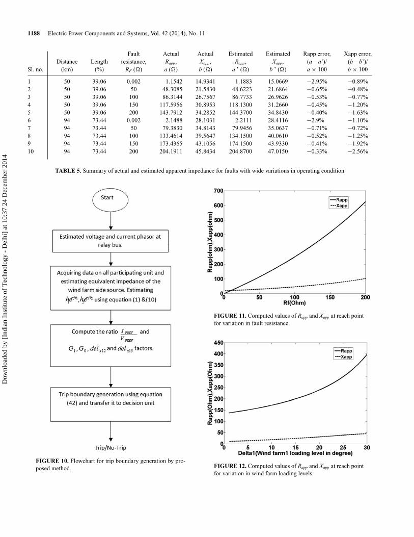
To achieve an accurate adaptive relay setting for thedistance relay at the wind farm side, information fromthree ends is required. The grid-side voltage, current, andimpedance information is necessary to compute factorsh1, h2δ1, δ2, G1, G0, delx12, and delx13. The flowchart of theproposed adaptive relay setting algorithm is shown in Fig-ure 10, which uses local information for developing the relaytripping characteristics. Table 5 depicts the summary of actualand estimated apparent impedance for fault conditions withvariations in operating parameters. Figure 11 presents varia-tions in Rapp and Xapp, with different fault resistance for fixedpower system operating conditions, and Figure 12 presents thecorresponding values with variation in wind farm loading levelδ. The extensive test results indicate that the maximum errorstays within 3%, showing the efficacy of the proposed distancerelay setting.
FIGURE 9. Trip boundaries for transmission system withchange in wind farm 1 loading level keeping wind farm 2loading level constant.
Dow
nloa
ded
by [
Indi
an I
nstit
ute
of T
echn
olog
y -
Del
hi]
at 1
0:37
24
Dec
embe
r 20
14
1188 Electric Power Components and Systems, Vol. 42 (2014), No. 11
Fault Actual Actual Estimated Estimated Rapp error, Xapp error,Distance Length resistance, Rapp, Xapp, Rapp, Xapp, (a – a’)/ (b – b’)/
Sl. no. (km) (%) RF (�) a (�) b (�) a ’ (�) b ’ (�) a × 100 b × 100
1 50 39.06 0.002 1.1542 14.9341 1.1883 15.0669 −2.95% −0.89%2 50 39.06 50 48.3085 21.5830 48.6223 21.6864 −0.65% −0.48%3 50 39.06 100 86.3144 26.7567 86.7733 26.9626 −0.53% −0.77%4 50 39.06 150 117.5956 30.8953 118.1300 31.2660 −0.45% −1.20%5 50 39.06 200 143.7912 34.2852 144.3700 34.8430 −0.40% −1.63%6 94 73.44 0.002 2.1488 28.1031 2.2111 28.4116 −2.9% −1.10%7 94 73.44 50 79.3830 34.8143 79.9456 35.0637 −0.71% −0.72%8 94 73.44 100 133.4614 39.5647 134.1500 40.0610 −0.52% −1.25%9 94 73.44 150 173.4365 43.1056 174.1500 43.9330 −0.41% −1.92%10 94 73.44 200 204.1911 45.8434 204.8700 47.0150 −0.33% −2.56%
TABLE 5. Summary of actual and estimated apparent impedance for faults with wide variations in operating condition
FIGURE 10. Flowchart for trip boundary generation by pro-posed method.
FIGURE 11. Computed values of Rapp and Xapp at reach pointfor variation in fault resistance.
FIGURE 12. Computed values of Rapp and Xapp at reach pointfor variation in wind farm loading levels.
Dow
nloa
ded
by [
Indi
an I
nstit
ute
of T
echn
olog
y -
Del
hi]
at 1
0:37
24
Dec
embe
r 20
14
Dubey et al.: Adaptive Distance Relaying Scheme for Transmission Network Connecting Wind Farms 1189
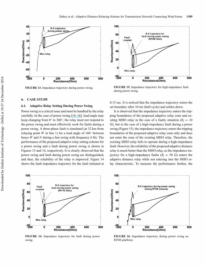
FIGURE 13. Impedance trajectory during power swing.
6. CASE STUDY
6.1. Adaptive Relay Setting During Power Swing
Power swing is a critical issue and must be handled by the relaycarefully. In the case of power swing [14–16], load angle maykeep changing from 0◦ to 360◦; the relay must not respond tothe power swing and must effectively work for faults during apower swing. A three-phase fault is simulated (at 32 km fromrelaying point W in line 1) for a load angle of 160◦ betweenbuses W and N during a fast swing with frequency 6 Hz. Theperformance of the proposed adaptive relay setting scheme fora power swing and a fault during power swing is shown inFigures 13 and 14, respectively. It is clearly observed that thepower swing and fault during power swing are distinguished,and thus, the reliability of the relay is improved. Figure 14shows the fault impedance trajectory for the fault initiated at
FIGURE 14. Impedance trajectory for fault during powerswing.
FIGURE 15. Impedance trajectory for high-impedance faultduring power swing.
0.15 sec. It is noticed that the impedance trajectory enters theset boundary after 10 ms (half-cycle) and settles down.
It is observed that the impedance trajectory enters the trip-ping boundaries of the proposed adaptive relay zone and ex-isting MHO relay in the case of a faulty situation (Rf = 10�), but in the case of a high-impedance fault during a powerswing (Figure 15), the impedance trajectory enters the trippingboundaries of the proposed adaptive relay zone only and doesnot enter the zone of the existing MHO relay. Therefore, theexisting MHO relay fails to operate during a high-impedancefault. However, the reliability of the proposed adaptive distancerelay is much better than the MHO relay, as the impedance tra-jectory for a high-impedance faults (Rf = 50 �) enters theadaptive distance relay while not entering into the MHO re-lay characteristic. To measure the performance further, the
FIGURE 16. Impedance trajectory during power swing onRTDS platform.
Dow
nloa
ded
by [
Indi
an I
nstit
ute
of T
echn
olog
y -
Del
hi]
at 1
0:37
24
Dec
embe
r 20
14
1190 Electric Power Components and Systems, Vol. 42 (2014), No. 11
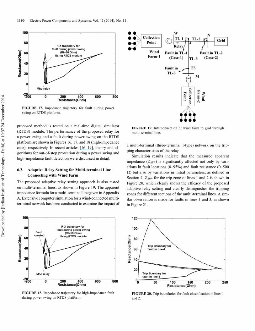
FIGURE 17. Impedance trajectory for fault during powerswing on RTDS platform.
proposed method is tested on a real-time digital simulator(RTDS) module. The performance of the proposed relay fora power swing and a fault during power swing on the RTDSplatform are shown in Figures 16, 17, and 18 (high-impedancecase), respectively. In recent articles [16–19], theory and al-gorithms for out-of-step protection during a power swing andhigh-impedance fault detection were discussed in detail.
6.2. Adaptive Relay Setting for Multi-terminal LineConnecting with Wind Farm
The proposed adaptive relay setting approach is also testedon multi-terminal lines, as shown in Figure 19. The apparentimpedance formula for a multi-terminal line given in AppendixA. Extensive computer simulation for a wind-connected multi-terminal network has been conducted to examine the impact of
FIGURE 18. Impedance trajectory for high-impedance faultduring power swing on RTDS platform.
FIGURE 19. Interconnection of wind farm to grid throughmulti-terminal line.
a multi-terminal (three-terminal T-type) network on the trip-ping characteristics of the relay.
Simulation results indicate that the measured apparentimpedance (ZAPP) is significantly affected not only by vari-ations in fault locations (0–95%) and fault resistance (0–500�) but also by variations in initial parameters, as defined inSection 4. ZAPP for the trip zone of lines 1 and 2 is shown inFigure 20, which clearly shows the efficacy of the proposedadaptive relay setting and clearly distinguishes the trippingzones for different sections of the multi-terminal lines. A sim-ilar observation is made for faults in lines 1 and 3, as shownin Figure 21.
FIGURE 20. Trip boundaries for fault classification in lines 1and 2.
Dow
nloa
ded
by [
Indi
an I
nstit
ute
of T
echn
olog
y -
Del
hi]
at 1
0:37
24
Dec
embe
r 20
14
Dubey et al.: Adaptive Distance Relaying Scheme for Transmission Network Connecting Wind Farms 1191
FIGURE 21. Trip boundaries for fault classification in lines 1and 3.
7. DISCUSSION
The adaptive distance relay setting for a transmission networkconnecting wind farms is achieved, including wide variationsin operating parameters of wind farms and power networks. Itis observed that the trip boundaries are significantly affectedby variations in operating conditions, and thus, the relay set-ting must be done accordingly to accommodate the possiblechanges. It is also found that the trip boundaries are signifi-cantly affected for a single wind farm connected to the gridcompared to multiple wind farms.
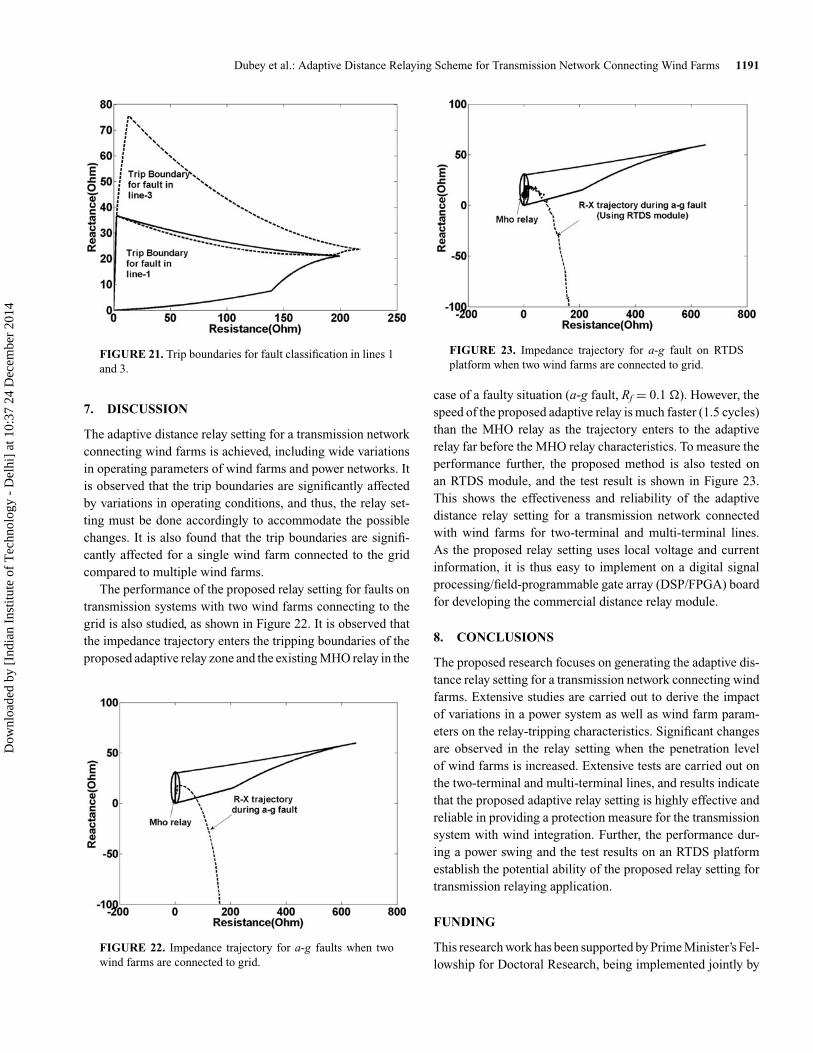
The performance of the proposed relay setting for faults ontransmission systems with two wind farms connecting to thegrid is also studied, as shown in Figure 22. It is observed thatthe impedance trajectory enters the tripping boundaries of theproposed adaptive relay zone and the existing MHO relay in the
FIGURE 22. Impedance trajectory for a-g faults when twowind farms are connected to grid.
FIGURE 23. Impedance trajectory for a-g fault on RTDSplatform when two wind farms are connected to grid.
case of a faulty situation (a-g fault, Rf = 0.1 �). However, thespeed of the proposed adaptive relay is much faster (1.5 cycles)than the MHO relay as the trajectory enters to the adaptiverelay far before the MHO relay characteristics. To measure theperformance further, the proposed method is also tested onan RTDS module, and the test result is shown in Figure 23.This shows the effectiveness and reliability of the adaptivedistance relay setting for a transmission network connectedwith wind farms for two-terminal and multi-terminal lines.As the proposed relay setting uses local voltage and currentinformation, it is thus easy to implement on a digital signalprocessing/field-programmable gate array (DSP/FPGA) boardfor developing the commercial distance relay module.
8. CONCLUSIONS
The proposed research focuses on generating the adaptive dis-tance relay setting for a transmission network connecting windfarms. Extensive studies are carried out to derive the impactof variations in a power system as well as wind farm param-eters on the relay-tripping characteristics. Significant changesare observed in the relay setting when the penetration levelof wind farms is increased. Extensive tests are carried out onthe two-terminal and multi-terminal lines, and results indicatethat the proposed adaptive relay setting is highly effective andreliable in providing a protection measure for the transmissionsystem with wind integration. Further, the performance dur-ing a power swing and the test results on an RTDS platformestablish the potential ability of the proposed relay setting fortransmission relaying application.
FUNDING
This research work has been supported by Prime Minister’s Fel-lowship for Doctoral Research, being implemented jointly by
Dow
nloa
ded
by [
Indi
an I
nstit
ute
of T
echn
olog
y -
Del
hi]
at 1
0:37
24
Dec
embe
r 20
14

1192 Electric Power Components and Systems, Vol. 42 (2014), No. 11
Science & Engineering Research Board (SERB) and Confed-eration of Indian Industry (CII), with industry partner RobertBosch.
REFERENCES
[1] Jongepier, G., and van der Sluis, L., “Adaptive distance protec-tion of a double circuit line,” IEEE Trans. Power Delivery, Vol.9, No. 3, pp. 1289–1297, July 1994.
[2] Rockefeller, G. D., “Fault protection with a digital computer,”IEEE Trans. Power App. Syst., Vol. PAS-88, No. 4, pp. 438–461,April 1969.
[3] Sachdev, M. S. (coordinator), “Computer relaying,” IEEE Tu-torial Course Text Pub. 79EH0148-7-PWR, 1979.
[4] Ghorbani, A., Mozafari, B., and Ranjbar, A. M., “Digital dis-tance protection of transmission lines in the presence of SSSC,”Int. J. Elect. Power Energy Syst., Vol. 43, pp. 712–719, Decem-ber 2012.
[5] Xia, Y. Q., Li, K. K., and David, A. K., ”Adaptive relay settingfor standalone digital distance protection,” IEEE Trans. PowerDelivery, Vol. 9, No. 1, pp. 480–491, 1993.
[6] Li, K. K., Lai, L. L., and David, A. K., “Stand alone intelligentdigital distance relay,” IEEE Trans. Power Delivery, Vol. 15,No. 1, pp. 137–142, February 2000.
[7] Phadke, A. G., and Thorp, J. S., Computer Relaying for PowerSystems, 2nd ed., Hoboken, NJ: Wiley, 2009.
[8] Xia, Y. Q., David, A. K., and Li, K. K., “High resistance faultson multi-terminal lines: Analysis, simulated studies an adaptivedistance relaying scheme,” IEEE Trans. Power Delivery, Vol. 9,No. 1, pp. 492–501, 1994.
[9] Li, K. K., Lai, L. L., and David, A. K., “Stand alone intelligentdigital distance relay,” IEEE Trans. Power Delivery, Vol. 15,No. 1, pp. 137–142, February 2000.
[10] Brahma, S. M., and Girgis, A. A., “Development of adaptiveprotection schemes for distribution systems with high penetra-tion of distribution generation,” IEEE Trans. Power Delivery,Vol. 19, No. 1, pp. 56–63, January 2004.
[11] Eriksen, P. B., “System operation with high wind genera-tion,” IEEE Power Energy Mag., Vol. 5, No. 6, pp. 65–74,November–December 2005.
[12] Pradhan, A. K., and Joos, G., “Adaptive distance relay settingfor lines connecting wind farms”, IEEE Trans. Energy Conver-sion, Vol. 22, No. 1, pp. 206–213, March 2007.
[13] Kamel, A., Alaam, M. A., Azmy, A. M., and Abdelaziz, A. Y.,“Protection coordination for distribution systems in presenceof distributed generators,” Elect. Power Compon. Syst., Vol. 41,No. 15, pp. 1555–1566, November 2013.
[14] Paudyal, S., Gokaraju, R., and Sachdev, M. S., “Application ofequal area criterion conditions in the time domain for out-of-step protection,” IEEE Trans. Power Delivery, Vol. 25, No. 4,pp. 600–609, April 2010.
[15] Paudyal, S., Gokaraju, R., Sachdev, M. S., and Cheng, S., “Out-of-step detection using energy equilibrium criterion in time do-main,” Elect. Power Compon. Syst., Vol. 37, No. 7, pp. 714–739,June 2009.
[16] Samantaray, S. R., Dubey, R. K., and Chitti Babu, B., “A noveltime-frequency transform based spectral energy function forfault detection during power swing,” Elect. Power Compon.Syst., Vol. 40, No. 8, pp. 881–897, April 2012.
[17] Rao, J. G., and Pradhan, A. K., “Differential power basedsymmetrical fault detection during power swing,” IEEE Trans.Power Delivery, Vol. 27, No. 3, pp. 1557–1564, July 2012.
[18] Dubey, R., and Samantaray, S. R., “Wavelet singular entropy-based symmetrical fault-detection and out-of-step protectionduring power swing,” IET Generat. Transm. Distribut., Vol. 7,No. 10, pp. 1123–1134, October 2013.
[19] Aziz, M. S. A., Hassan, M. A. M., and Zahab, E. A., “High-impedance faults analysis in distribution networks using anadaptive neuro fuzzy inference system,” Elect. Power Compon.Syst., Vol. 40, No. 11, pp. 1300–1318, August 2012.
APPENDIX A
The apparent impedance calculation of multi-terminal line(Figure 19) with initial conditions [8, 12] is derived asfollows:
h1 = 0.97, h2 = 1.01, Z1SW = Z0SW = 5e j85,
Z1SM = Z0SM = 20e j85, Z1SN = Z0SN = 10e j85.
δ1 = 200, δ2 = 100, Z1W J = Z1W N1 = 37.76e j86,
Z0W J = Z0W N1 = 134.49e j81.3, Z1J N = 37.76e j86.
Z0J N = 134.49e j81.3, Z1J M = 18.88e j86,
Z0J M = 67.25e j81.3.
Case 1: Apparent Impedance Calculation forMulti-terminal HV Line Connected to Wind Farm WhenFault (LG) Occurs at F1
The expression of apparent impedance measured by a relay forfault occurring in transmission line 1 is
Z AW = n ∗ Z1L1 + 3 ∗ RF
χW S11 + 2χ1 + χ0(1 + β0),
where
χW S11 =
(3RF + Z∑
)λW S1
(1 − Z1W λW S1), χ1 = Z1SN F1
Z1SW F1 + Z1SN F1,
χ0 = Z0SN F1
Z0SW F1 + Z0SN F1, β0 = Z0W F1 − Z1W F1
Z1W F1
= Z0W J − Z1W J
Z1W J.
λW S1 = (1 − λ)
(Z1M L + Z N L ) (Z1W + Z1N1),
λ = h1e− jδ1 − (h1e− jδ1 − h2e− jδ2
) Z1N L
Z1N L + Z1M L,
Z1W = Z1SW + Z1W F1.
Z1N1 = Z1SNEQU + Z1F1N1, Z1SNEQU = Z1N L Z1M L
Z1N L + Z1M L,
Z0SNEQU = Z0N L Z0M L
Z0N L + Z0M L, Z1W L = Z1SW + Z1W J .
Dow
nloa
ded
by [
Indi
an I
nstit
ute
of T
echn
olog
y -
Del
hi]
at 1
0:37
24
Dec
embe
r 20
14

Dubey et al.: Adaptive Distance Relaying Scheme for Transmission Network Connecting Wind Farms 1193
Z1M L = Z1SM + Z1M J , Z1N L = Z1SN + Z1J N ,
Z1SN1F = Z1SNEQU + Z1N1F , Z0SN F = Z0SNEQU + Z0N F .
Z1SW F = Z1SW + Z1W F , Z0SW F = Z0SW + Z0W F ,
E AN
E AW= h1e− jδ1 ,
E AM
E AW= h2e− jδ2 .
Case 2: Apparent Impedance Calculation forMulti-terminal HV Line Connected to Wind Farm WhenFault (LG) Occurs at F2
The expression of apparent impedance measured by a relay fora fault occurring in transmission line 2 is
Z AP P = VAW
IAW + β0 I0W= Z1W J + �Z N EW ,
where
�ZNEW = ZNEW1 + ZNEW2 + ZNEW3,
ZNEW1 = 3RF(Z�+3RF )∗η
1−Z1W L η+Z J F μ+ 2σ1σW T + β0σ1σW T
,
σ1 = Z1N F + Z1SNZ1W L Z1M L
Z1W L+Z1M L+ Z1N L
ZNEW2 = 2σ1 Z J F + σ0 Z0J F(Z�+3RF )∗η
1−Z1W L η+Z J F μ+ 2σ1σW T + β0σ1σW T
,
ZNEW3 = −Z J F
η
μ+ (1−Z1W Lη+Z J F μ)(2σ1σW T +β0σ1σW T )
(Z�+3RF )μ
.
η = IW J
E AW= (1 − λ)
Z1W L + Z1N L Z1M L
Z1N L+Z1M L
,
μ = IN J
E AW= − (1 − ρ)
Z1N L + Z1W L Z1M L
Z1W L+Z1M L
,
ρ = h1e− jδ1 + (1 − h2e− jδ2
) Z1W L
Z1W L + Z1M L.
σ0 = Z0N F + Z0SNZ0W L Z0M L
Z0W L+Z0M L+ Z0N L
, σ1W T = Z1M L
Z1W L + Z1M L,
σ0W T = Z0M L
Z0W L + Z0M L, � = (2σ1 Z1J F + σ0 Z0J F ) VAF
Z� + 3RF
− Z1J FμE AW
Case 3: Apparent Impedance Calculation forMulti-terminal HV Line Connected to Wind Farm WhenFault (LG) Occurs at F3
This case analysis is the same as that in Case 2 except for theexchange of external parameters between N and M and lineimpedances between TL-2 and TL-3.
BIOGRAPHIES
Rahul K. Dubey received Master in Technology (M. Tech.)in the department of Electrical Engineering, National Instituteof Technology Rourkela, Orissa, India in 2012. He is currentlyworking towards the Ph.D. degree in power system engineeringat the Department of Electrical Engineering, Indian Instituteof Technology (IIT), New Delhi, India. His research interestincludes Intelligent Protection, Digital Signal Processing, SoftComputing, FACTs.
Subhransu Ranjan Samantaray received a B.Tech. in electri-cal engineering from UCE Burla, India, in 1999 and a Ph.D. inpower system engineering from the Department of Electronicsand Communication Engineering, National Institute of Tech-nology, Rourkela, India, in 2007. Dr. Samantaray holds theposition of Assistant Professor in the School of Electrical Sci-ences, Indian Institute of Technology Bhubaneswar, India. Hevisited the Department of Electrical and Computer Engineer-ing, McGill University, Montreal, Canada as a Post-DoctoralResearch Fellow in 2008 and 2009-10. His major research in-terests include intelligent protection for transmission systems(including FACTs) and microgrid protection with distributedgeneration and dynamic security assessment in large powernetworks.
Bijay Ketan Panigrahi (SM’06) is an Associate Professorwith the Department of Electrical Engineering, Indian Instituteof Technology (IIT), New Delhi. Prior to joining IIT Delhi, hewas a Lecturer at the University College of Engineering, Burla,Sambalpur, Orissa, for 13 years. His research interestsAre inthe areas of intelligent control of FACTS devices, applicationof advanced DSP techniques for power quality assessment,and application of soft computing techniques to power systemoperation and control.
Dow
nloa
ded
by [
Indi
an I
nstit
ute
of T
echn
olog
y -
Del
hi]
at 1
0:37
24
Dec
embe
r 20
14