Multi-mode relaying for power consumption reduction
28
HAL Id: inria-00470533 https://hal.inria.fr/inria-00470533v1 Submitted on 6 Apr 2010 (v1), last revised 25 Oct 2010 (v3) HAL is a multi-disciplinary open access archive for the deposit and dissemination of sci- entific research documents, whether they are pub- lished or not. The documents may come from teaching and research institutions in France or abroad, or from public or private research centers. L’archive ouverte pluridisciplinaire HAL, est destinée au dépôt et à la diffusion de documents scientifiques de niveau recherche, publiés ou non, émanant des établissements d’enseignement et de recherche français ou étrangers, des laboratoires publics ou privés. Multi-mode relaying for power consumption reduction Cédric Lévy-Bencheton, Guillaume Villemaud, Tanguy Risset, Doreid Ammar, Clément Reboul To cite this version: Cédric Lévy-Bencheton, Guillaume Villemaud, Tanguy Risset, Doreid Ammar, Clément Reboul. Multi-mode relaying for power consumption reduction. [Research Report] RR-7245, 2010. inria- 00470533v1
-
Upload
khangminh22 -
Category
Documents
-
view
1 -
download
0
Transcript of Multi-mode relaying for power consumption reduction
HAL Id: inria-00470533https://hal.inria.fr/inria-00470533v1
Submitted on 6 Apr 2010 (v1), last revised 25 Oct 2010 (v3)
HAL is a multi-disciplinary open accessarchive for the deposit and dissemination of sci-entific research documents, whether they are pub-lished or not. The documents may come fromteaching and research institutions in France orabroad, or from public or private research centers.
L’archive ouverte pluridisciplinaire HAL, estdestinée au dépôt et à la diffusion de documentsscientifiques de niveau recherche, publiés ou non,émanant des établissements d’enseignement et derecherche français ou étrangers, des laboratoirespublics ou privés.
Multi-mode relaying for power consumption reductionCédric Lévy-Bencheton, Guillaume Villemaud, Tanguy Risset, Doreid
Ammar, Clément Reboul
To cite this version:Cédric Lévy-Bencheton, Guillaume Villemaud, Tanguy Risset, Doreid Ammar, Clément Reboul.Multi-mode relaying for power consumption reduction. [Research Report] RR-7245, 2010. �inria-00470533v1�

appor t de r echerche
ISS
N0
24
9-6
39
9IS
RN
INR
IA/R
R--
00
00
--F
R+
EN
G
Domaine 3
INSTITUT NATIONAL DE RECHERCHE EN INFORMATIQUE ET EN AUTOMATIQUE
Multi-mode relaying for power consumption
reduction
Cédric LÉVY-BENCHETON — Guillaume VILLEMAUD — Tanguy RISSET — Doreid
AMMAR — Clément REBOUL
N° 0000
Avril 2010

Centre de recherche INRIA Grenoble – Rhône-Alpes655, avenue de l’Europe, 38334 Montbonnot Saint Ismier
Téléphone : +33 4 76 61 52 00 — Télécopie +33 4 76 61 52 52
Multi-mode relaying for power consumption reduction
Cédric LÉVY-BENCHETON∗, Guillaume VILLEMAUD∗ , TanguyRISSET∗ , Doreid AMMAR∗ , Clément REBOUL∗
Domaine : Réseaux, systèmes et services, calcul distribuéÉquipe-Projet SWING
Rapport de recherche n° 0000 — Avril 2010 — 24 pages
Abstract: As multi-mode is becoming standard in current mobile terminals, the ne-cessity to reduce power consumption increases. In this paper, we propose to utilizemulti-mode to cut the energy needs, by relaying on the least power consuming com-munication mode. The most convenient way to implement multi-mode is undoubtfullyprovided by Software Defined Radio (SDR). The idea is to replace the ever-increasingembedded radio chips by a single, general purpose, processor.
We show that a multi-mode relay, composed of Software Defined Radios, has animpact on power reduction. We elaborate different scenarios to verify this proposition,considering that this multi-mode ability is based on an SDR. Firstly, we propose an802.11g-to-UMTS relay scheme, where a mobile terminal relays other users’ signal.We enounce different rules to minimize the global power consumption through multi-mode relaying. Then, we find different results for an 802.15.4-to-802.11g relay. Afterfurther inquiries, we explain how the most intuitive solution is not always the bestone. Following a more realistic approach, we use network simulations to determine theimportant parameters having an impact on power consumption.
Key-words: multi-mode relay, software defined radio, power reduction
∗ Université de Lyon, INRIA, INSA-Lyon, CITI, F-69621, France

Relai multi-mode dans un but de réduction de la
consommation d’énergie
Résumé : Les terminaux mobiles actuels possédant tous plusieurs interfaces de communicationen standard (ils sont dits multi-mode), il devient nécessaire de réduire leur consommationd’énergie. Dans ce papier, nous proposons de réduire les coûts énergétiques, grâce àla mise en place d’un relai sur le mode de communication le moins consommateurd’énergie. Pour ce faire, nous basons notre travail sur les spécifications de la RadioLogicielle, qui permet de remplacer l’accumulation de circuits de communication parun unique processeur générique. Ainsi, la Radio Logicielle permet une relative facilitéd’implémentation du multi-modes.
Nous montrons qu’un relai multi-mode, composé de radios logicielles, permet deréduire la consommation d’énergie. Pour cela, nous élaborons différents scénarios dansle but de vérifier cette proposition, en considérant que le multi-mode est obtenu grâce àdes programmes exécutés par la radio logicielle. Dans un premier temps, nous étudionsun scénario de relai 802.11g-vers-UMTS, où un terminal mobile joue le rôle du relaipour les autres utilisateur. Nous énonçons différentes régles permettant la minimisationde la consommation globale du système, dans le cadre de ce relai multi-mode. Dansun second temps, l’application de ces règles à un relai 802.15.4-vers-802.11g mène àdes résultats différents. Après examination, nous expliquons comment la solution laplus intuitive n’est pas toujours la meilleure. En utilisant une approche plus réaliste viades simulations réseaux, nous déterminons plusieurs paramètres importants ayant unimpact sur la consommation d’énergie.
Mots-clés : relai multi-mode, radio logicelle, réduction d’énergie

Multi-mode relaying for power consumption reduction 3
Contents
1 Introduction 4
2 Software defined radio and relays, toward a lower power consumption 5
2.1 State of the art . . . . . . . . . . . . . . . . . . . . . . . . . . . . . . 52.2 Our approach . . . . . . . . . . . . . . . . . . . . . . . . . . . . . . 6
3 Complexity study 7
3.1 A per-bit complexity analysis . . . . . . . . . . . . . . . . . . . . . . 83.2 Algorithmic complexity evaluation . . . . . . . . . . . . . . . . . . . 8
4 Power consumption estimation 10
4.1 Numerical power consumption . . . . . . . . . . . . . . . . . . . . . 104.2 Radio power consumption . . . . . . . . . . . . . . . . . . . . . . . 104.3 Channel conditions . . . . . . . . . . . . . . . . . . . . . . . . . . . 12
5 Multi-mode relay to achieve power reduction 13
5.1 Scenario presentation . . . . . . . . . . . . . . . . . . . . . . . . . . 135.2 Protocols parameters in a multi-mode context . . . . . . . . . . . . . 14
6 802.11g-to-UMTS simulations 14
6.1 Analytical study . . . . . . . . . . . . . . . . . . . . . . . . . . . . . 146.2 Temporary conclusion . . . . . . . . . . . . . . . . . . . . . . . . . 15
7 802.11g-to-802.15.4 simulations 16
7.1 A crucial need to consider upper layers . . . . . . . . . . . . . . . . . 177.2 Network simulations for a better precision . . . . . . . . . . . . . . . 177.3 Temporary conclusion . . . . . . . . . . . . . . . . . . . . . . . . . 197.4 Network simulations with transmission constraints . . . . . . . . . . 19
8 Discussion and conclusions 21
RR n° 0000
Multi-mode relaying for power consumption reduction 4
1 Introduction
Multi-mode is an established feature in all current mobile terminals. By enabling com-munication on different modes, such as IEEE 802.11g [14] or UMTS [1], this propertybrings us closer to an unlimited connectivity, an important need for all mobile users. Amulti-mode terminal can switch its communication interface in order to connect to thebest suitable mode, in term of application needs (QoS), users’ choices (access cost), orenergy reduction.
However, current devices rely on a number of dedicated chipsets to provide connec-tivity. With one chipset associated to one mode, the terminal cost is raising drasticallyalong with its power consumption. A solution might lie in Software Defined Radio(SDR), where the multiple chipsets found in current devices are replaced by a singlegeneric purpose processor running algorithms. Thus, a multi-mode SDR implementsdifferent modes as different algorithms. Since all modern standards share commonali-ties, those algorithms are reusable between different modes. This leads to a facilitatedimplementation of new modes, and a better power efficiency of parallel communica-tions on two different modes.
Still, another problem remains. How can operators ensure an all time connectivity,without generating new costs? Relay usage is one possible answer. A relay is a devicetransmitting data from users in bad conditions to an access point. Such relays can bedeployed by operators or be mobile. In the latter case, users’ terminals act as potentialrelays.
In our work, we take advantage of a multi-mode relay in order to reduce the net-work global power consumption. In our mobile multi-mode relay, a Primary User (PU)communicates with Secondary Users (SUs) on one mode denoted R mode, and withan Access Point (AP) on another mode denoted D Mode. Contrary to classical worksin the relaying field, we focus on the physical layer power consumption, includingnot only the transmission power but also numerical and analogical power consump-tions. We do not consider the energy consumption induced by upper layer. An SDRbrings many advantages when dealing with multi-mode: its adaptation possibilitiesbenefit to the energy reduction. Since mobile terminals are power-limited, we proposea careful study of all elements (related to the physical layer) involved in their powerconsumption. Firstly, we evaluate the numerical complexity for different communica-tion modes, which is closely tied to the power consumption in an SDR. We focus onthe IEEE 802.11g (WiFi) [14], a WLAN standard, 3GPP UMTS [1], a voice and datalong-range mobile communication mode, and the IEEE 802.15.4 low-power WPAN(Zigbee) [15].
We explore a list of the current related works in the SDR and relay domains, as wellas their usages in power reduction, and expose our approach in section 2. We detail theprevious stages concerning the complexity evaluation and the numerical power con-sumption in section 3. We also present the analogical power consumption and differentchannels models, in section 4. We then look at the energy consumption of different re-lay scenarios, where PU is relaying an 802.11g-connected SU to UMTS gateway. Weestimate the power consumption of a mobile PU acting as a relay for a fixed or severalSecondary Users (SUs) with the cost of direct UMTS connections. We also study thebehaviour of a relay at fixed distance from a SU. We realize those scenarios throughMatlab simulations and express relay rules to reduce the global power consumption,in section 6. In addition, we study an 802.15.4-to-802.11g relay, and determine that amore realistic approach is needed. We show that analytical conclusions are not alwaysthe right ones, by taking into account the consumption of network control packets and
RR n° 0000
Multi-mode relaying for power consumption reduction 5
passive overhearing in a network simulator, WSNet [9], in section 7. Finally, we dis-cuss about the need of a realistic study to predict the power consumption behaviour ofa multi-mode relay in section 8.
2 Software defined radio and relays, toward a lower
power consumption
2.1 State of the art
Different works already study the benefits of SDR and relay. We present an overviewof these works, focusing particularly on energy savings. Limiting the terminal powerconsumption remains at the core of many domains related to mobility: from the ter-minals conception to the applications and services usages. Multi-mode can help toachieve energy reduction, a critical issue in mobility. At the physical layer level, In-whee et al. select the less consuming mode with an algorithm taking into account therequired quality of service, the cost for the user and the terminal remaining battery lifein [17]. This approach raises the terminal lifetime for a given amount of data. Authorsrely on realistic radio energy values to evaluate the terminal consumption but do notconsider the numerical cost. While users tend to utilize mobile services, their discov-ery is a consuming process. A terminal can also benefit from multi-mode in a contextof ubiquitous services as presented in [8]. The paper expresses the necessity of powerreduction in a pervasive service discovery scheme, by reconfiguring a multi-mode ter-minal to communicate on the most energy efficient interface. However, the choice isnot only lead by the lowest power consumption, but needs to take into account the ser-vice type. Authors denote that a “low-power" standard (here Bluetooth) is actually notthe less consuming mode, due to a higher consumption per packet. However, they donot consider relaying.
As presented before, an SDR provides the adaptability required to change mode dy-namically. Different works enhance and facilitate the terminal reconfiguration. Berle-mann implements a realistic protocol stack, sharing processing blocks between 802.11gand UMTS [5]. However, this work is more focused on the network access and trans-port layers, instead of the physical layer. This gap is filled by Montium, a low-powerSDR architecture, sharing processing blocks between different parallel modes [25].Montium can be at the core of mobile SDR terminals, but requires an adapted pro-gramming of the different communication blocks, which must be preinstalled, or down-loaded over the air. However, multi-mode is not evaluated.
An SDR has reconfiguration capabilities, which brings the flexibility needed toguarantee an always available connection. This reconfiguration, where the terminalchanges mode, is decided by a metric based on different criteria. Although classicalmetrics look at the channel conditions as in [10], where the mode with the highestSNR is chosen, long term energy savings are not guaranteed. More interesting metricstake into account other parameters. Ganesan proposes a local metric, computed at theterminal, to evaluate the interferences caused by cognitive users for a primary user,both communicating on a licensed frequency [11]. When the primary user is detected,cognitive users negotiate with each other to change communication mode. Reconfigu-ration is at the centre of the IEEE SCC41 Working Group [16], via P1900.4 [12]. Theirproposal is to send a small file, the radio enabler, containing all the needed informationfor the mobile terminal to select the best suitable network (number of operations per
RR n° 0000

Multi-mode relaying for power consumption reduction 6
second, frequency, datarate, and so on). Each mode having to broadcast its own radioenabler, it does not reveal to be power efficient.
The energy consumption cannot be reduced at the terminal only. Relaying allowsusers to connect to closer access points in the case of fixed relays, or to share their con-nection in the case of mobile relays. Jiang et al. apply reconfiguration to self-organizedfixed rely stations [19]. To prevent handover process near cell border, different fixedrelays communicate with the cellular network to evaluate the need of relaying a mobileuser. This proposal reduces the radio power consumption and interferences, but not inmulti-mode.
A relay has many advantages. It enables a better efficiency on network coverage asCavalcanti et al. present an heterogeneous multi-hop wireless network [7]. In this net-work, mobile users can use other users’ terminals as a relay to contact the access pointthrough multi-hop communication. An algorithm estimates the “connectivity opportu-nity" from user preferences, datarate needs and channel conditions. Capacity and errorrate improve but no estimation on the power consumption is given. Relaying reducesthe transmission power. Wang, Srinivasan and Chua increase a sensor network lifetimeup to four time thanks to mobile relays [30]. Relays are simple sensors with a largerbattery. Mobile relays provide a better network autonomy, reduction of capacity bot-tlenecks, cost savings and more importantly, a normal behaviour of the mobile sensorwhen not acting as a relay.
Seddik et al. minimize the outage probability by dynamically adjusting the trans-missions power values in Amplify-and-Forward multi-relay networks [26]. Their adap-tive strategies bring a larger energy reduction than classical power allocation approaches,and at any distance from the access point, thanks to relaying. Nourizadeh et al. exposethe advantages and disadvantages of mobile relay: greater network capacity, lower con-sumption when relaying a single user and cost savings in network deployment for anequivalent user satisfaction [24]. In cooperative clusters, a terminal has personal gainsby sharing its connection for the good of the network: using adapted strategies, overallenergy is saved [2, 3]. Those strategies allow communications at different data ratesinside the cluster, and at a fixed data rate with the access point. However, authors onlyuse radio power consumption, and do not consider multi-mode in the gain provided tomulti-users.
As in SDR, the decision for a terminal whether to act as a relay or be relayed de-pends on a metric. Madan et al. improve global energy consumption in a cooperativenetwork by using relays with beamforming capacity [22]. Authors compute the cost foreach node to acquire its Channel State Information locally and select multiple relaysthrough an adapted strategy, which guarantees the minimal consumption for an opti-mum number of relays. Hwang and Ko show that a sub-optimal relay selection avoidsa constant listening of the channel conditions and thus, increases network lifetime [13].Relay selection is performed after fading measurements. The impact of multi-hop relayselection on a sensor network power consumption is presented in [21]: the best relay isthe one with the highest battery charge. Demonstrated with realistic front-end values,this energy optimized relay selection increases the network lifetime.
2.2 Our approach
In our approach, we include the numerical complexity in the terminal power consump-tion. We also implement network simulations for a more realistic evaluation of thepower consumption, by taking into account control packets and passive overhearing.Our goal is to minimize the network global power consumption by combining SDR
RR n° 0000
Multi-mode relaying for power consumption reduction 7
and multi-mode relays. Compared to SDR, classical radios using one chipset per modeare not power efficient in multi-mode. The flexibility provided by an SDR allows powerreduction, through multi-mode reconfiguration and resource sharing.
We show how the minimization of a terminal power consumption by communicat-ing on the most efficient mode helps to reduce the global power consumption. Sincean SDR implements a mode via processing blocks, we study the algorithmic complex-ity of 802.11g, UMTS and 802.15.4 for a given terminal. In order to compare thosedifferent modes, we evaluate the complexity for a single data bit and deduce the termi-nal numerical power consumption. We justify this per-bit approach as an appropriateway to discriminate different standards. Following these results, we compute the radioconsumption for every mode and select the most efficient one. Thus, we minimize theterminal power consumption.
We combine several of those SDR terminals to form a multi-mode relay scheme,and evaluate the global power consumption. The scope of this paper is the physicallayer power consumption, and thus, we do not consider upper layers in our estimation.We focus on the physical layer, including the numerical and analogical power con-sumption, unlike classical relay works which only take into account the transmissionpower.
In our relay proposal, one Primary User (denoted PU), whose terminal can act asa relay for one or several Secondary User(s) (denoted SU(s)), is in communicationwith an Access Point (denoted AP). Using Matlab simulations, we compare the powerconsumption of PU relaying SU with the cost of direct connections, for different casesin 802.11g-to-UMTS and 802.15.4-to-802.11g relays. We define the “No-Relay Zone":a zone where relaying has no positive impact on global power consumption. Then, weexpress relay rules to minimize the global power consumption at all time, thanks tomulti-mode relay.
Nevertheless, those rules are not applicable in the case of an 802.15.4-to-802.11grelay, due to the cost induced by MAC layer control packets and passive overhear-ing. Thus, we propose a more realistic evaluation, by relying on a network simulator.We choose WSNet, a realistic wireless network simulator developed at the CITI Lab-oratory [9]. WSNet is an open-source simulator providing realistic PHY and MAClayers, with a modular interface allowing rapid development of add-ons, coded in C.To perform our simulations, we designed a multi-mode WSNet plugin and extendedthe power evaluation module by integrating the numerical consumption for each mode.
3 Complexity study
In software radio, a physical layer is implemented through programs. A multi-modeSDR runs different algorithms corresponding to the selected modes at the same time.To achieve our goal, we propose to communicate on the mode minimizing the SDRpower consumption, which is composed of two parts: the numerical power consump-tion, depending on the algorithmic complexity, and the radio power consumption. Inthis section, we evaluate precisely the numerical complexity for the different algo-rithms used in 802.11g, UMTS and 802.15.4. As we compare different modes, wepresent the results as a number of operations per bit. We justify the relevance of thisper-bit analysis in the purpose of comparing different modes.
RR n° 0000

Multi-mode relaying for power consumption reduction 8
Table 1: Important properties considered for the algorithmic complexity evaluation
802.11g
Data bitrate 6 Mbps 54 MbpsCarrier frequency 2,400 MhzPhysical layer OFDMEncoding Convolutional (rate 1/2) Convolutional (rate 3/4)Modulation BPSK 64-QAMNumber of carrier 64 subcarriers (48 data, 4 preambles, 12 null)Spreading factor -Chips per second -Frame size (bits) 1500 * 8Header size (bits) 30 * 8
UMTS 802.15.4
Data bitrate 384 kbps 20 kbpsCarrier frequency 1,900 Mhz (uplink) & 2,100 Mhz (downlink) 868 MhzPhysical layer Spreading & scrambling SpreadingEncoding Convolutional (rate 1/2) DifferentialModulation QPSK BPSKNumber of carrier 1 1Spreading factor 4 15Chips per second 3.84 M 300 kFrame size (bits) 3840 133 * 8Header size (bits) 90 (DCCH: control channel) 8 * 8
3.1 A per-bit complexity analysis
The numerical complexity of a standard mostly depends on the selected parameters (i.e.
modulation, code rate, ...). Complex bit transformations such as coding, spreading orOFDM mapping lead to a high complexity. Each mode has different steps in transmis-sion, where databits are transformed, coded, modulated, assembled into frames, andsent to a receiver at a given radio bitrate. Our desire is to compare different modes ona common basis. Hence, we take into account all operations realized by a mode for asingle data bit, and compute the number of operations per (data) bit, or bitop.
3.2 Algorithmic complexity evaluation
In order to evaluate the numerical power consumption, we compute the algorithmiccomplexity per bit, or bitop, for every mode, by referring to Neel, Robert and Reed’swork [23]. This bitop value allows us to compare different standards. We proceed toa careful study of each mode physical layer to get per-bit results. In fact, the differentdatabit transformations must be accounted for at each step: encoding, mapping, FFT,and so on. The number of operation for each step is first evaluated per frame (a nec-essary step in certain operations), before being converted into bitop and rounded up tothe upper integer.
We present the bitop (rounded to the upper integer) for the transmission and recep-tion chains in selected modes of 802.11g, UMTS and 802.15.4 on Table 2. The firstnoticeable result comes from the receiving operations needed to recover numerical bits.This costly process is required to correct all anomalies the signal encounters over the
RR n° 0000

Mu
lti-mo
de
relayin
gfo
rp
ow
erco
nsu
mp
tion
redu
ction
9
Table 2: Detailed algorithmic complexity for selected communication modes (in bitop)TRANSMISSION
802.11g 6 Mbps 54 Mbps UMTS 384 kbps 802.15.4 20 kbps
Scrambling 18 18 CRC 6 Coding 4Coding 74 66 Coding 83 Spreading 15Puncturing 0 26 Puncturing 18 Mapping 75Interleaving 11 7 First interleaving 0Mapping 10 3 Frame segmenta-
tion7
IFFT 195 22 Rate matching 7Multiplexing 253Second nterleaving 80OVSF Spreading 20Scrambling 80Mapping 60DCCH 131
TOTAL TX 308 142 TOTAL TX 745 TOTAL TX 94
RECEPTION
802.11g 6 Mbps 54 Mbps UMTS 384 kbps 802.15.4 20 kbps
FIR filtering 9 1 FIR filtering 1,548 FIR filtering 108Interpolation &decimation
53 6 Interpolation &decimation
555 Interpolation &decimation
65
Frequency adjust-ment
18 18 Slot synchroniza-tion
301 Frequency adjust-ment
2
Phase correction 2 2 Frame synchro-nization
36 Phase correction 2
Correlation 14 14 Descrambling 322 Correlation 1FFT 195 22 Rake 80 Demapping 75Demapping 10 3 DeMapping 60 Despreading 15Deinterleaving 11 11 Second deinterleav-
ing80 Differential decod-
ing4
Depuncturing 0 26 Demultiplexing 253Viterbi decoding 155 188 Rate matching 7Descrambling 18 18 Frame desegmenta-
tion7
First deinterleaving 0Depuncturing 18Viterbi Decoding 248CRC 6
TOTAL RX 485 309 TOTAL RX 3,521 TOTAL RX 272
RR
n°0000
Multi-mode relaying for power consumption reduction 10
air. It is lower in 802.11g, which uses OFDM with a high data bitrate, and thus com-pensates the complexity by a lower bitop. As we can see, the most important bitops in802.11g come from the convolutional encoding and IFFT in emission, from the Viterbidecoding and FFT in reception. Due to the BPSK modulation process, 6 Mbps is morecostly than 54 Mbps, where intuition would lead to the contrary. However, the bitopis almost equivalent for higher datarates (24 Mbps, 36 Mbps, 48 Mbps and 54 Mbps).We choose to represent 54 Mbps only. In UMTS at 384 kbps, the multiplexing processhas a high bitop cost due to the high number of memory access, while descramblingand Viterbi decoding represent a major complexity in reception. In UMTS, the bitop ismore consequent at low rates, where the spreading is more important to achieve the re-quired 3.84 MChips. Hence, the Rake complexity increases with the spreading factor.In 802.15.4, the mapping cost is largely induced by the high spreading factor. We didnot evaluate the cost of 802.15.4 for other bitrates.
4 Power consumption estimation
We now evaluate the power required to transmit or receive one single data bit in thechosen mode, Pbit , the power cost per bit. As presented before, the terminal powerconsumption is divided into two parts : Pnum, the numerical power consumption, andPr f , the radio power consumption. Pnum depending on the algorithmic complexitiesand the processor architecture. Pr f being tied to the radio front-end architecture andthe transmission power output (dependant of the channel conditions), we consider amulti-band radio front-end adapted to multi-mode. Hence:
Pbit = Pnum +Pr f (1)
4.1 Numerical power consumption
After we have determined the algorithmic complexities for each mode, we evaluate thenumerical power consumption, Pnum (in Joule per bit), following [28]:
Pnum = N ∗C ∗V 2dd (2)
with N being the number of cycles, C the processor’s switching capacitance (in Farad)and Vdd the input voltage (in Volt). For a given processor, at fixed frequency, thenumber of cycles increases with the algorithmic complexity. This leads to a higherpower consumption. To express Pnum in Joule per bit, we need to consider one operationper cycle and set N to the bitop evaluated previously. We consider the ARM 968E-Sprocessor [4], running generic algorithms at one operation per cycle. For the requiredinput voltage of Vdd = 1.2V, we calculate C = 97.3pF.
4.2 Radio power consumption
We separate the radio power consumption into two parts: the radio-frequency front-endpower consumption, and the transmission power. The front-end power consumption de-pends on its architecture and activity. We consider a multi-mode radio-frequency front-end, capable of receiving simultaneously 802.11g, UMTS and 802.15.4 signals [6]. Weevaluate the radio power consumption, Pr f (in Joule per bit), using [27]:
Pr f = NT [(Ton +Tst)Ptx +TonPO]+NR(Ron +Rst)Prx (3)
RR n° 0000

Multi-mode relaying for power consumption reduction 11
802.11g 802.11g 802.15.40
0.5
1
1.5
2
2.5x 10
−7
Pow
er c
onsu
mpt
ion
per
bit (
Joul
e)
802.11g 802.11g 802.15.4 UMTS0
0.5
1
1.5
2
2.5x 10
−6
Pnum
TX
Pnum
RX
Prf TX @ 8m
Prf RX
Zoom 10x
0.331
0.566
384 kbps(a) (b)
0.68
0.432
0.52
0.5
0.381
0.132 0.104
0.493
0.885
0.518
6 Mbps 20 kbps 6 Mbps 54 Mbps 20 kbps
0.434
0.2
54 Mbps
0.0370.077
Figure 1: Terminal power cost per bit, Pbit , in Joule, for the transmitting and receivingcomponent of Pnum and Pr f . (a) zoomed on 802.11g and 802.15.4, (b) compared withUMTS.
with Ptx and Prx (in Watt) being the power consumption of the front-end components,respectively when emitting and receiving and PO the output signal power (in Watt). Ton
and Ron represent the time to send or receive one data bit, Tst and Rst the wakeup timeof the circuit in transmission and reception, NT and NR the amount of time the trans-mitter/receiver is switched on per period. We separate transmission from reception: forNT = 1, NR = 0 and reciprocally. We also set Tst =Rst = 0, because they are negligeablein practice. The transmission power output, PO, depends on the channel conditions andthe distance with the receiver. We explain how to evaluate it in section 4.3. By settingTon or Ron to the duration of a single databit, we express Pr f in Joule per bit.
We explore the energy needs to send and receive a single bit on Fig. 1. The nu-merical power consumption, Pnum, remains constant at any distance. We observe thesame behaviour for the radio reception. The radio power mostly depends on the trans-mission power, adjusted according to the receiver’s channel conditions and distance.Indeed, the only varying parameter in the radio power transmission is PO. As the dis-tance increases, the radio consumption becomes predominant in the evaluation of Pbit .To obtain a good estimation, we evaluate the radio transmission power for a distanceof 8 meters between two users.
We note the high cost of UMTS, due its high radio power consumption: the nu-merical power represents approximately a quarter of the radio power. In 802.11g, thenumerical and radio power are almost identical to transmit and receive one data bit at6 Mbps. At 54 Mbps, the radio energy is very low compared to the numerical part.This is due to the shortest time to send one single data bit. In 802.15.4, the radio andnumerical parts have approximately the same cost.
We now compare the transmission and reception energy costs, by adding numer-ical and radio transmission. The high consumption of the transmission in low datarates is due to the time taken to send a single bit. In high data rates, the major en-ergy needs come from the receiving side: the implemented algorithms, providing suchspeed, take a lot of processing power. Moreover, the increasing distance can also be-come a problem, by raising PO too high. Focusing on the numerical side, we remark the
RR n° 0000
Multi-mode relaying for power consumption reduction 12
0 5 10 15 20 25 30−100
−90
−80
−70
−60
−50
−40
Distance AP−PU (m)
Pat
hlos
s (d
Bm
)
802.11g CITI802.11g ITU−R n=3802.15.4 CITI802.15.4 Friis
openspace
walls > 3
(a)
Access pointMeasurements path
(b)
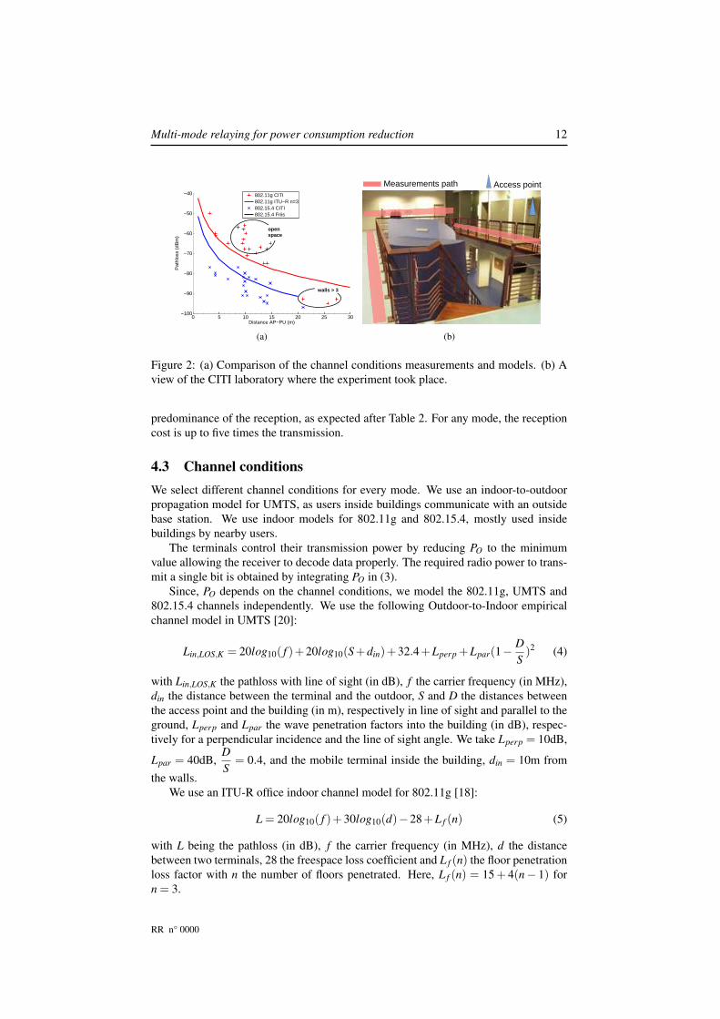
Figure 2: (a) Comparison of the channel conditions measurements and models. (b) Aview of the CITI laboratory where the experiment took place.
predominance of the reception, as expected after Table 2. For any mode, the receptioncost is up to five times the transmission.
4.3 Channel conditions
We select different channel conditions for every mode. We use an indoor-to-outdoorpropagation model for UMTS, as users inside buildings communicate with an outsidebase station. We use indoor models for 802.11g and 802.15.4, mostly used insidebuildings by nearby users.
The terminals control their transmission power by reducing PO to the minimumvalue allowing the receiver to decode data properly. The required radio power to trans-mit a single bit is obtained by integrating PO in (3).
Since, PO depends on the channel conditions, we model the 802.11g, UMTS and802.15.4 channels independently. We use the following Outdoor-to-Indoor empiricalchannel model in UMTS [20]:
Lin,LOS,K = 20log10( f )+20log10(S+din)+32.4+Lperp +Lpar(1−D
S)2 (4)
with Lin,LOS,K the pathloss with line of sight (in dB), f the carrier frequency (in MHz),din the distance between the terminal and the outdoor, S and D the distances betweenthe access point and the building (in m), respectively in line of sight and parallel to theground, Lperp and Lpar the wave penetration factors into the building (in dB), respec-tively for a perpendicular incidence and the line of sight angle. We take Lperp = 10dB,
Lpar = 40dB,D
S= 0.4, and the mobile terminal inside the building, din = 10m from
the walls.We use an ITU-R office indoor channel model for 802.11g [18]:
L = 20log10( f )+30log10(d)−28+L f (n) (5)
with L being the pathloss (in dB), f the carrier frequency (in MHz), d the distancebetween two terminals, 28 the freespace loss coefficient and L f (n) the floor penetrationloss factor with n the number of floors penetrated. Here, L f (n) = 15+ 4(n− 1) forn = 3.
RR n° 0000
Multi-mode relaying for power consumption reduction 13
APSU
SU 1
to
N
...
D mode
PU
dAP−PU d
PU−SUd
AP−SU
(a)
D mode
AP PU
SU
SU 1
to
N
...
R mode
dAP−PU d
PU−SUd
AP−SU
(b)
PU dataSU data
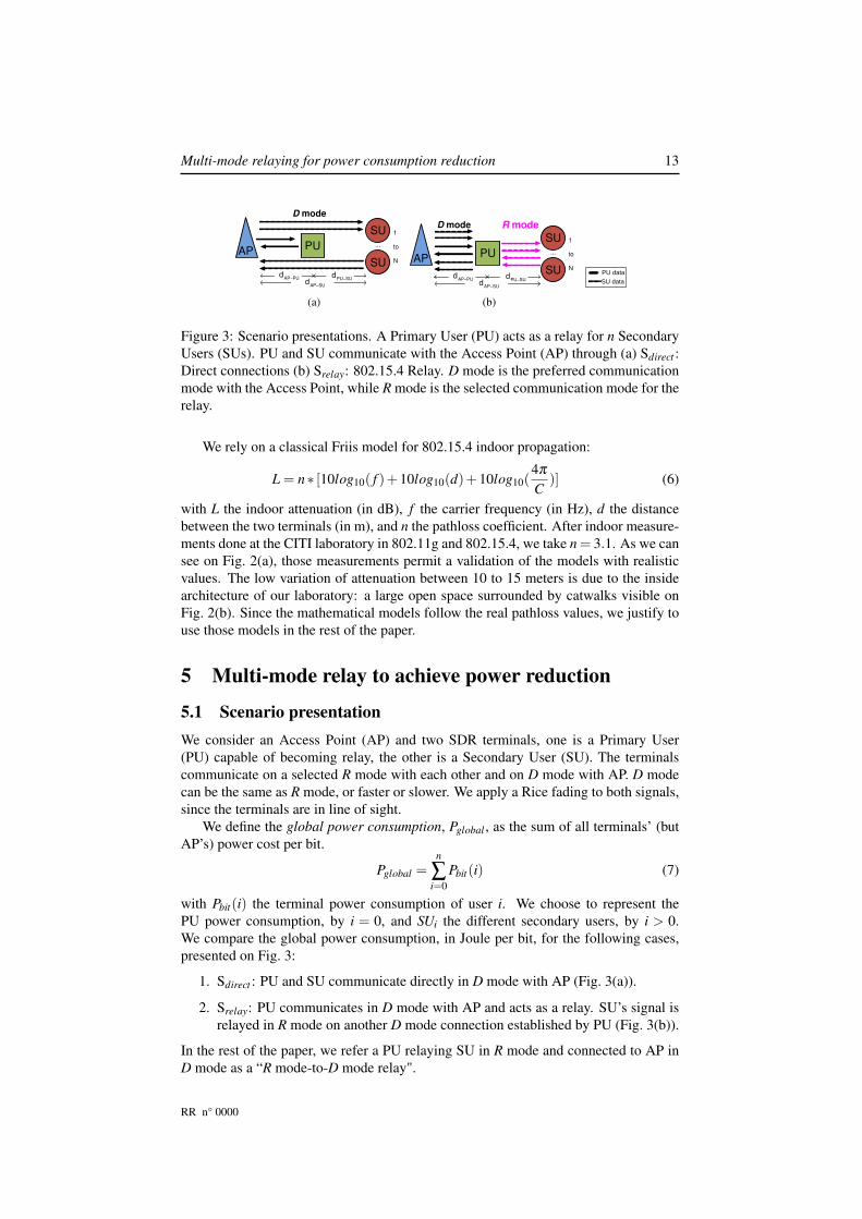
Figure 3: Scenario presentations. A Primary User (PU) acts as a relay for n SecondaryUsers (SUs). PU and SU communicate with the Access Point (AP) through (a) Sdirect :Direct connections (b) Srelay: 802.15.4 Relay. D mode is the preferred communicationmode with the Access Point, while R mode is the selected communication mode for therelay.
We rely on a classical Friis model for 802.15.4 indoor propagation:
L = n∗ [10log10( f )+10log10(d)+10log10(4π
C)] (6)
with L the indoor attenuation (in dB), f the carrier frequency (in Hz), d the distancebetween the two terminals (in m), and n the pathloss coefficient. After indoor measure-ments done at the CITI laboratory in 802.11g and 802.15.4, we take n = 3.1. As we cansee on Fig. 2(a), those measurements permit a validation of the models with realisticvalues. The low variation of attenuation between 10 to 15 meters is due to the insidearchitecture of our laboratory: a large open space surrounded by catwalks visible onFig. 2(b). Since the mathematical models follow the real pathloss values, we justify touse those models in the rest of the paper.
5 Multi-mode relay to achieve power reduction
5.1 Scenario presentation
We consider an Access Point (AP) and two SDR terminals, one is a Primary User(PU) capable of becoming relay, the other is a Secondary User (SU). The terminalscommunicate on a selected R mode with each other and on D mode with AP. D modecan be the same as R mode, or faster or slower. We apply a Rice fading to both signals,since the terminals are in line of sight.
We define the global power consumption, Pglobal , as the sum of all terminals’ (butAP’s) power cost per bit.
Pglobal =n
∑i=0
Pbit(i) (7)
with Pbit(i) the terminal power consumption of user i. We choose to represent thePU power consumption, by i = 0, and SUi the different secondary users, by i > 0.We compare the global power consumption, in Joule per bit, for the following cases,presented on Fig. 3:
1. Sdirect : PU and SU communicate directly in D mode with AP (Fig. 3(a)).
2. Srelay: PU communicates in D mode with AP and acts as a relay. SU’s signal isrelayed in R mode on another D mode connection established by PU (Fig. 3(b)).
In the rest of the paper, we refer a PU relaying SU in R mode and connected to AP inD mode as a “R mode-to-D mode relay".
RR n° 0000

Multi-mode relaying for power consumption reduction 14
Table 3: Important parameters to consider for simulations
802.11g UMTS 802.15.4
Data bitrate 6 Mbps 54 Mbps 384 kbps 20 kbpsRF TX Value(mW)
338 338 338 1
RF RX Value(mW)
198.8 [6] 198.8 [6] 198.8 [6] 1 [29] +
Minimum PO
(dBm)-20 - - -20
Maximum PO
(dBm)10 - - 0
RX Sensitiv-ity (dBm)
-87 -71 -90 -92
Pathlossmodel
(5) (5) (4) (6)
MAC Layer ∗ CSMA/CA CSMA/CA FDD/TDMA CSMA (no RTS/CTS)Controlpackets size(bytes) ∗
RTS: 36, CTS: 28, ACK: 26 - -
+[29] proposes an integrated 802.15.4 transceiver with Ptx = 3.28mW and Prx = 3.29mW. As we separatethe numerical and radio consumptions, we reduce our front-end consumption to 1mW.∗In network simulations only.
5.2 Protocols parameters in a multi-mode context
We present the different parameters needed to evaluate the terminal and the globalenergy consumption in Table 3. The RF TX and RX Value correspond to the radiofront-end energetic consumption, Ptx and Prx in (3). The receiver sensitivity is theminimum strength for a received signal to be decoded accurately. Pathloss models,introduced above, are needed to adapt the transmission power to the received signalstrength. The calculation of PO is the difference of that value with transmitted signalpower minus the pathloss. The MAC layer and the size of control packets tell users themoment to send and receive data. We only need them during network simulations, andwe show their importance in section 7.
6 802.11g-to-UMTS simulations
In this section, we present an analytical study of an 802.11g-to-UMTS relay powerconsumption. In this analytical study, we evaluate the complexity and power con-sumption of selected modes with no interferences, no control packets and no passiveoverhearing. We then implement Srelay and Sdirect scenarios on Matlab, and comparetheir global power consumption.
6.1 Analytical study
An UMTS base station, abusively denoted AP in a matter of coherence, is emitting atcontrolled power to all its users. A Primary User (PU) is an SDR terminal which can actas a relay for Secondary User(s) (SU(s)), placed farther away from AP. For simplicity,AP, PU and SU are aligned, and all terminals follow a straight line when moving.
RR n° 0000

Multi-mode relaying for power consumption reduction 15
800 850 900 950 10000.6
0.7
0.8
0.9
1
1.1
1.2
Distance AP−PU (m)
Nor
mal
ized
glo
bal p
ower
con
sum
ptio
n pe
r bi
t
S
relayS
direct
(a)
0 200 400 600 800 10000.6
0.7
0.8
0.9
1
1.1
1.2
Distance AP−PU (m)
Nor
mal
ized
glo
bal p
ower
con
sum
ptio
n pe
r bi
t
S
relayS
direct
(b)
Figure 4: Global power consumption per bit, normalized by direct connections fordifferent scenario. For a mobile Primary User (PU) and (a) a fixed Secondary User (SU)at dAP−SU = 1,000m, (b) a Secondary User (SU) moving with PU at dPU−SU = 50m.
In UMTS, a signaling process is continuously emitted by AP and received by allterminals for power control. In order to simulate these signals fluctuations, we apply anindependent Ricean fading to all communications. Moreover, we resort to an uncappedPO, so long range line of sight 802.11g communications can happen.
We evaluate the gains of relaying in the following scenarios (Fig. 4):
• PU is moving from AP toward a fixed SU, far from AP. Srelay brings 20% inpower gains compared to Sdirect , until PU moves closer to SU, where PU entersa “No-Relay Zone": a zone where relaying has no major gain compared to directconnections. In the “No-Relay Zone", Srelay consumption is 5 to 10% lower thanSdirect . When PU is too close to SU, direct connections are privileged, as thegains are null, or negative, with 5% more energy required (Fig. 4(a)).
• PU and SU are separated by a fixed distance, dPU−SU . They conserve this dis-tance while moving together from AP toward the cell border. In this case, Srelay
is interesting when PU and SU move farther from AP, with 5% gains on Srelay inaverage (Fig. 4(b)).
• PU is relaying multiple SUs, ranging from 1 to n. To express the worst casescenario, we place all n SUs at the position of the farthest SU. The global powerconsumption of Srelay of n+2 SUs is better than Sdirect consumption for n SUs,when PU is far from SUs. For the same number of SUs, the gains of relaying arenear 35%. When PU is moving toward SUs, this gain lowers to reach 10 to 15%(Fig. 5).
6.2 Temporary conclusion
Based on the previous results, the following rules allow to minimize the global powerconsumption (Fig. 6).
When PU is close to AP (Fig. 6 ➂), PU becomes a relay for SUs far from AP(Fig. 6 ➀), with gains above 20%. By adding mobility, the terminal acting as a PU willrelay for a certain period, before entering the “No-Relay Zone". At that moment, PUstops relaying and becomes a new SU (Fig. 6 ➀). Later, that terminal can become anew SU and be relayed by a new PU.
RR n° 0000
Multi-mode relaying for power consumption reduction 16
800 850 900 950 10004
5
6
7
8
9
10x 10
−5
Distance AP−PU (m)
Glo
bal p
ower
con
sum
ptio
n pe
r bi
t (Jo
ule)
Srelay
Sdirect
n = 3
n = 5
n = 4
n = 5
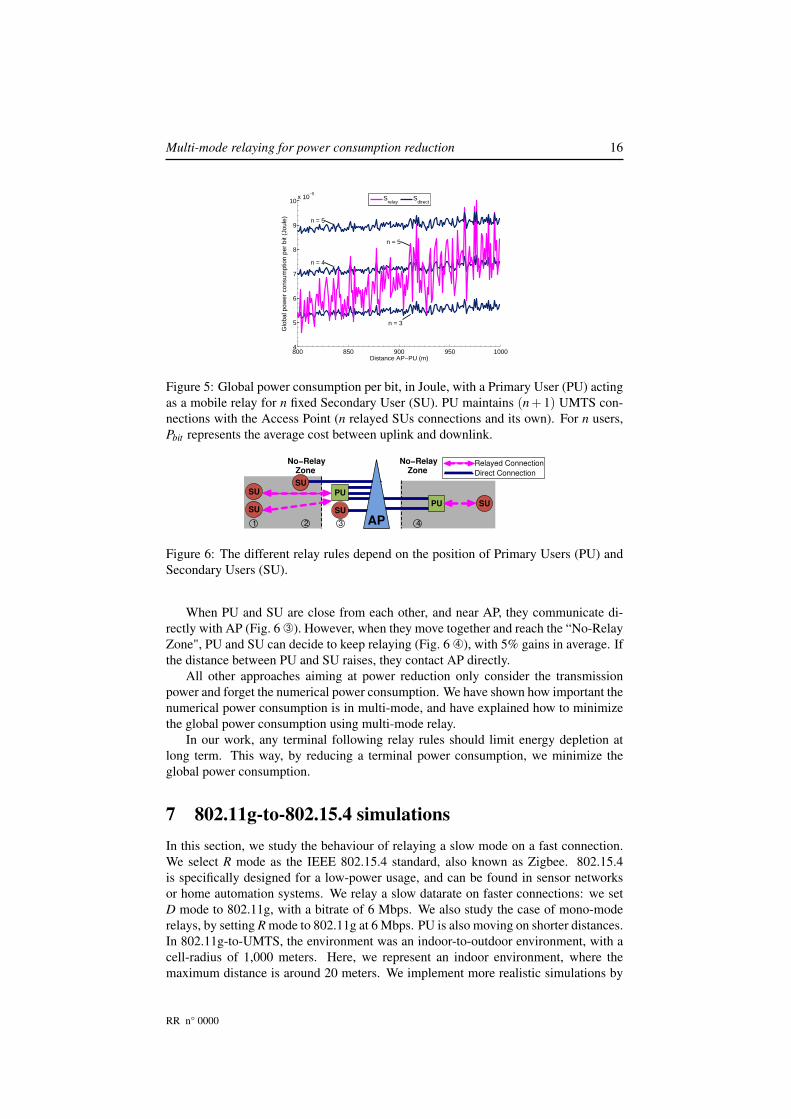
Figure 5: Global power consumption per bit, in Joule, with a Primary User (PU) actingas a mobile relay for n fixed Secondary User (SU). PU maintains (n+1) UMTS con-nections with the Access Point (n relayed SUs connections and its own). For n users,Pbit represents the average cost between uplink and downlink.
No−RelayZone
1
No−RelayZone
AP
PU
SUSUPU
2 3 4
SU
SUSU
Relayed Connection
Direct Connection
Figure 6: The different relay rules depend on the position of Primary Users (PU) andSecondary Users (SU).
When PU and SU are close from each other, and near AP, they communicate di-rectly with AP (Fig. 6 ➂). However, when they move together and reach the “No-RelayZone", PU and SU can decide to keep relaying (Fig. 6 ➃), with 5% gains in average. Ifthe distance between PU and SU raises, they contact AP directly.
All other approaches aiming at power reduction only consider the transmissionpower and forget the numerical power consumption. We have shown how important thenumerical power consumption is in multi-mode, and have explained how to minimizethe global power consumption using multi-mode relay.
In our work, any terminal following relay rules should limit energy depletion atlong term. This way, by reducing a terminal power consumption, we minimize theglobal power consumption.
7 802.11g-to-802.15.4 simulations
In this section, we study the behaviour of relaying a slow mode on a fast connection.We select R mode as the IEEE 802.15.4 standard, also known as Zigbee. 802.15.4is specifically designed for a low-power usage, and can be found in sensor networksor home automation systems. We relay a slow datarate on faster connections: we setD mode to 802.11g, with a bitrate of 6 Mbps. We also study the case of mono-moderelays, by setting R mode to 802.11g at 6 Mbps. PU is also moving on shorter distances.In 802.11g-to-UMTS, the environment was an indoor-to-outdoor environment, with acell-radius of 1,000 meters. Here, we represent an indoor environment, where themaximum distance is around 20 meters. We implement more realistic simulations by
RR n° 0000
Multi-mode relaying for power consumption reduction 17
0 1 2 3 4 5 6 7 8 9 10 11 12 13 14 15 16 17 18 19 202.8
3
3.2
3.4
3.6
3.8
4
4.2
4.4x 10
−7
Distance AP−PU (m)
Glo
bal p
ower
con
sum
ptio
n pe
r bi
t (Jo
ule)
Srelay
(R mode: 802.15.4)
Srelay
(R mode: 802.11g)
Sdirect
(a)
0 1 2 3 4 5 6 7 8 9 10 11 12 13 14 15 16 17 18 19 200
0.5
1
1.5
2
2.5
x 10−6
Distance AP−PU (m)
Glo
bal p
ower
con
sum
ptio
n pe
r bi
t (Jo
ule)
Srelay
(R mode: 802.15.4)
Srelay
(R mode: 802.11g)
Sdirect n = 7
n = 3
n = 5
n = 7
n = 5
(b)
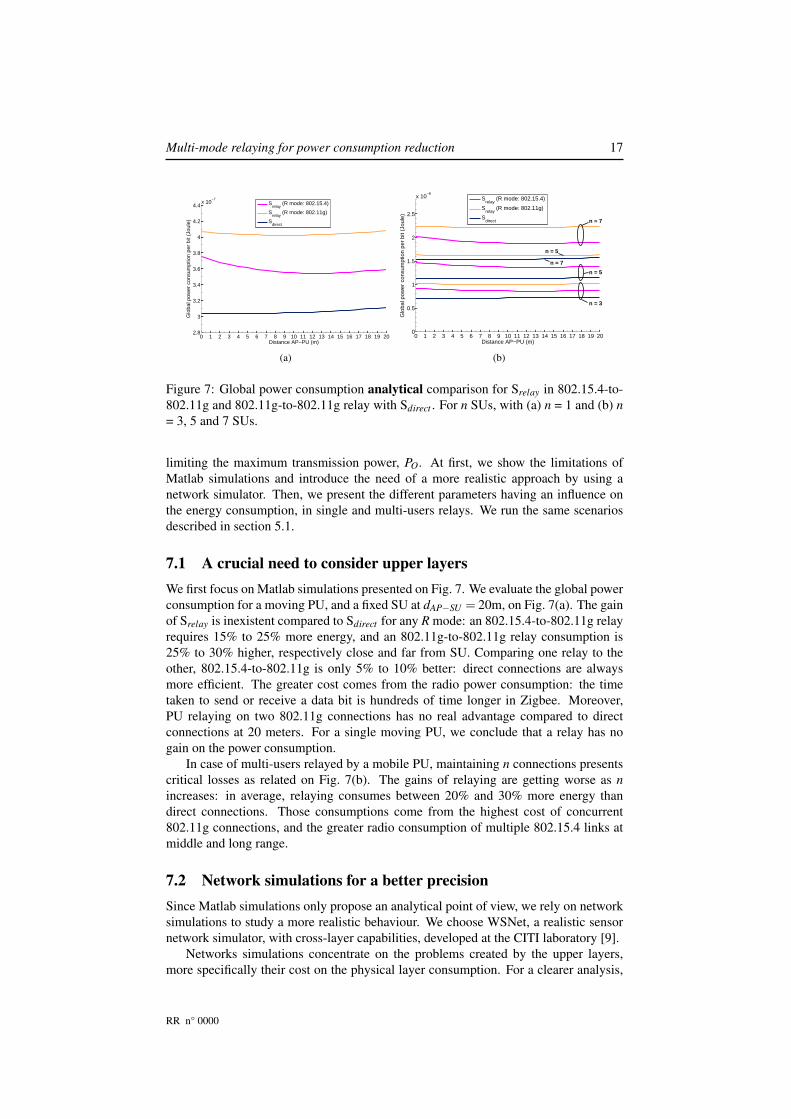
Figure 7: Global power consumption analytical comparison for Srelay in 802.15.4-to-802.11g and 802.11g-to-802.11g relay with Sdirect . For n SUs, with (a) n = 1 and (b) n
= 3, 5 and 7 SUs.
limiting the maximum transmission power, PO. At first, we show the limitations ofMatlab simulations and introduce the need of a more realistic approach by using anetwork simulator. Then, we present the different parameters having an influence onthe energy consumption, in single and multi-users relays. We run the same scenariosdescribed in section 5.1.
7.1 A crucial need to consider upper layers
We first focus on Matlab simulations presented on Fig. 7. We evaluate the global powerconsumption for a moving PU, and a fixed SU at dAP−SU = 20m, on Fig. 7(a). The gainof Srelay is inexistent compared to Sdirect for any R mode: an 802.15.4-to-802.11g relayrequires 15% to 25% more energy, and an 802.11g-to-802.11g relay consumption is25% to 30% higher, respectively close and far from SU. Comparing one relay to theother, 802.15.4-to-802.11g is only 5% to 10% better: direct connections are alwaysmore efficient. The greater cost comes from the radio power consumption: the timetaken to send or receive a data bit is hundreds of time longer in Zigbee. Moreover,PU relaying on two 802.11g connections has no real advantage compared to directconnections at 20 meters. For a single moving PU, we conclude that a relay has nogain on the power consumption.
In case of multi-users relayed by a mobile PU, maintaining n connections presentscritical losses as related on Fig. 7(b). The gains of relaying are getting worse as n
increases: in average, relaying consumes between 20% and 30% more energy thandirect connections. Those consumptions come from the highest cost of concurrent802.11g connections, and the greater radio consumption of multiple 802.15.4 links atmiddle and long range.
7.2 Network simulations for a better precision
Since Matlab simulations only propose an analytical point of view, we rely on networksimulations to study a more realistic behaviour. We choose WSNet, a realistic sensornetwork simulator, with cross-layer capabilities, developed at the CITI laboratory [9].
Networks simulations concentrate on the problems created by the upper layers,more specifically their cost on the physical layer consumption. For a clearer analysis,
RR n° 0000
Multi-mode relaying for power consumption reduction 18
8 9 10 11 12 13 14 15 16 17 18 19 20 21 22 23 24 257.5
8
8.5
9
9.5
10
10.5x 10
−7
Distance AP−PU (m)
Glo
bal p
ower
con
sum
ptio
n pe
r bi
t (Jo
ule)
S
relayS
direct
802.11g passive overhearing
(a)
8 9 10 11 12 13 14 15 16 17 18 19 20 21 22 23 24 257.5
8
8.5
9
9.5
10
10.5x 10
−7
Distance AP−PU (m)
Glo
bal p
ower
con
sum
ptio
n pe
r bi
t (Jo
ule)
S
relayS
direct
(b)
8 9 10 11 12 13 14 15 16 17 18 19 20 21 22 23 24 250
0.5
1
1.5
2
2.5
3
3.5
4
4.5x 10
−6
Distance AP−PU (m)
Glo
bal p
ower
con
sum
ptio
n pe
r bi
t (Jo
ule)
Srelay
Sdirect
n = 1
n = 2
n = 3
n = 5
n = 7
(c)
8 9 10 11 12 13 14 15 16 17 18 19 20 21 22 23 24 250
0.5
1
1.5
2
2.5
3
3.5
4
4.5x 10
−6
Distance AP−PU (m)
Glo
bal p
ower
con
sum
ptio
n pe
r bi
t (Jo
ule)
Srelay
Sdirect
n = 5
n = 7
n = 2
n = 3
n = 1
(d)
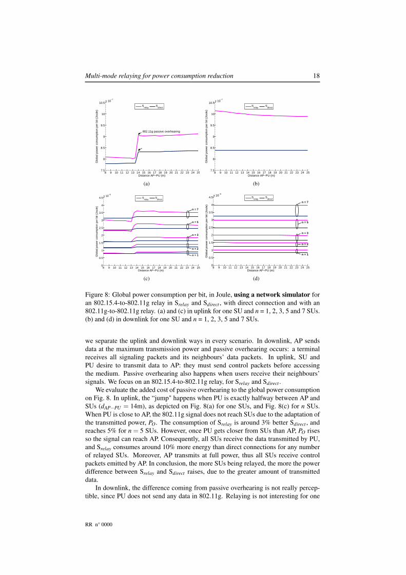
Figure 8: Global power consumption per bit, in Joule, using a network simulator foran 802.15.4-to-802.11g relay in Srelay and Sdirect , with direct connection and with an802.11g-to-802.11g relay. (a) and (c) in uplink for one SU and n = 1, 2, 3, 5 and 7 SUs.(b) and (d) in downlink for one SU and n = 1, 2, 3, 5 and 7 SUs.
we separate the uplink and downlink ways in every scenario. In downlink, AP sendsdata at the maximum transmission power and passive overhearing occurs: a terminalreceives all signaling packets and its neighbours’ data packets. In uplink, SU andPU desire to transmit data to AP: they must send control packets before accessingthe medium. Passive overhearing also happens when users receive their neighbours’signals. We focus on an 802.15.4-to-802.11g relay, for Srelay and Sdirect .
We evaluate the added cost of passive overhearing to the global power consumptionon Fig. 8. In uplink, the “jump" happens when PU is exactly halfway between AP andSUs (dAP−PU = 14m), as depicted on Fig. 8(a) for one SUs, and Fig. 8(c) for n SUs.When PU is close to AP, the 802.11g signal does not reach SUs due to the adaptation ofthe transmitted power, PO. The consumption of Srelay is around 3% better Sdirect , andreaches 5% for n = 5 SUs. However, once PU gets closer from SUs than AP, PO risesso the signal can reach AP. Consequently, all SUs receive the data transmitted by PU,and Srelay consumes around 10% more energy than direct connections for any numberof relayed SUs. Moreover, AP transmits at full power, thus all SUs receive controlpackets emitted by AP. In conclusion, the more SUs being relayed, the more the powerdifference between Srelay and Sdirect raises, due to the greater amount of transmitteddata.
In downlink, the difference coming from passive overhearing is not really percep-tible, since PU does not send any data in 802.11g. Relaying is not interesting for one
RR n° 0000

Multi-mode relaying for power consumption reduction 19
or n SUs, with a power consumption 20% more important than Sdirect , as presented onFig.8(b)(d). Since we assume AP has an unlimited energy, we do not consider its powerconsumption. In Sdirect , the global power consumption comes from the reception only.However, in Srelay, PU has to relay data from AP to SU. The transmission of R modeis taken into account. The cost introduced by those 802.15.4 connections remains toohigh to compensate 802.11g receptions at such distances.
7.3 Temporary conclusion
The first results show that an 802.15.4-to-802.11g relay has no real interest comparedto direct connections, neither in uplink nor in downlink. We showed that such relaywas not efficient through Matlab simulation, which lacked realism. After implement-ing the same simulations with more refined parameters on WSNet, the relay powerconsumption remained above direct connections. Even though 802.15.4 has a higherradio consumption than 802.11g, it alone cannot explain the higher cost compared tomultiple long range 802.11g connections. This has lead us to consider the influence ofdifferent parameters on power consumption.
We focus on two factors: passive overhearing, when SUs receive 802.11g data emit-ted by AP, and control packets, required before data transmission. When relaying on802.15.4, we propose to neglect control packets by limiting their transmission power,and reduce 802.11g overhearing by disabling SUs’ interface. In the next section, wequantify the gains of those two different approaches on relaying.
7.4 Network simulations with transmission constraints
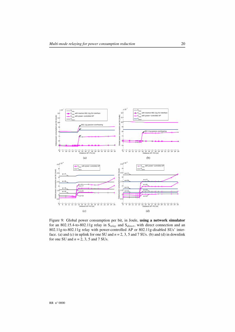
As presented previously in section 7.2, network simulations allow us to observe theinfluence of control packets and passive overhearing on the network energy consump-tion. We evaluate two solutions to reduce the global power consumption: disablingSU’s 802.11g radio interface, and limiting AP transmission power. The deactivationof the 802.11g interface at the SUs’ drastically reduces the global power consumptionas presented on Fig. 9, but might introduce problems: a multi-mode terminal worksas a mono-mode one. In this case, denoted “Srelay with inactive 802.11g interface",SUs remove all costs linked to their 802.11g interface, and only suffer from 802.15.4overhearing.
In uplink, deactivating the 802.11g interface at the SUs’ gains around 35% of en-ergy when PU is near AP, and over 40% when PU is approaching SU, as we can seeon Fig.9(a). The more important energy consumption when PU is close to SU comesfrom the fact that PU sends 802.11g control packets at the maximum allowed power,to prevent hidden terminals. In downlink, high relaying gains are also noticeable onFig 9(b), with an energy consumption reduced by 30% for one SU.
By default, 802.11g control packets are always transmitted at full power. Here,we limit the transmission power, so data and control packets only covers the distancebetween AP and PU. We apply this limit on both sides: PU control packets are alsopower-constrained. In this case, SUs’ 802.11g interface is active and ready to receive.In uplink, when PU is close to AP, we notice a 35% power reduction on Fig. 9(a).For multi-users, relaying brings over 50% gains to the global power consumption, aspresented on Fig. 9(c). Still, when PU is reaching half distance, the high cost of 802.11gpassive overhearing makes this scheme reach 15% of Sdirect global power consumptionfor one SU, and up to 30% for n = 7 SUs. For large values of n, when PU is too
RR n° 0000
Multi-mode relaying for power consumption reduction 20
8 9 10 11 12 13 14 15 16 17 18 19 20 21 22 23 24 254
5
6
7
8
9
10
11
12
x 10−7
Distance AP−PU (m)
Glo
bal p
ower
con
sum
ptio
n pe
r bi
t (Jo
ule)
Srelay
Srelay
with inactive 802.11g SU interface
Srelay
with power−controlled AP
Sdirect
802.11g passive overhearing
(a)
8 9 10 11 12 13 14 15 16 17 18 19 20 21 22 23 24 254
5
6
7
8
9
10
11
12
x 10−7
Distance AP−PU (m)
Glo
bal p
ower
con
sum
ptio
n pe
r bi
t (Jo
ule)
Srelay
Srelay
with inactive 802.11g SU interface
Srelay
with power−controlled AP
Sdirect
802.11g passive overhearing
(b)
8 9 10 11 12 13 14 15 16 17 18 19 20 21 22 23 24 250
0.5
1
1.5
2
2.5
3
3.5
4
4.5x 10
−6
Distance AP−PU (m)
Glo
bal p
ower
con
sum
ptio
n pe
r bi
t (Jo
ule)
S
relay with power−controlled AP
Sdirect
n = 7
n = 5
n = 3
n = 2
n = 3
n = 5
n = 7
(c)
8 9 10 11 12 13 14 15 16 17 18 19 20 21 22 23 24 250
0.5
1
1.5
2
2.5
3
3.5
4
4.5x 10
−6
Distance AP−PU (m)
Glo
bal p
ower
con
sum
ptio
n pe
r bi
t (Jo
ule)
S
relay with power−controlled AP
Sdirect
n = 3
n = 2
n = 5
n = 7
n = 7
n = 5
n = 3
n = 2
(d)
Figure 9: Global power consumption per bit, in Joule, using a network simulator
for an 802.15.4-to-802.11g relay in Srelay and Sdirect , with direct connection and an802.11g-to-802.11g relay with power-controlled AP or 802.11g-disabled SUs’ inter-face. (a) and (c) in uplink for one SU and n = 2, 3, 5 and 7 SUs. (b) and (d) in downlinkfor one SU and n = 2, 3, 5 and 7 SUs.
RR n° 0000
Multi-mode relaying for power consumption reduction 21
close from SUs, Srelay consumption increases due 802.11g passive overhearing, butstill remains interesting (around 10% better for n = 7 SUs).
In downlink, relaying at limited power is the most interesting with a 30% gainwhen PU is near AP, as presented on Fig. 9(b): 802.11g control packets do not reachthe different SUs. Relaying multi-users provides the same performances, as noticedon Fig. 9(d) with around 45% of energy saved for n = 2 SUs. At middle range, therelaying gain is lower, but still 7% more efficient than direct connections for one SU.For multi-users, the gains are more noticeable at middle-range, with 20% gains forn = 5 SUs. However, for PU close to n = 7 SUs, relaying is 2% worse than Sdirect .
Power-constrained transmission allows to efficiently reduce the global power con-sumption, while not suffering of the disadvantages of 802.11g-deactivation at the SUs’.Compared to direct connections, this relay provides a lower cost and a good coveragefor all users. However, the problem of hidden terminal remains. Hence, a new terminalmust send a request to be detected, while PU should respond at full power during avery limited time. The new terminal might also be reported to AP by PU, if its max-imum power is not sufficient. Moreover, current SUs might check the quality of theirconnection with AP: terminals can rely on a negotiation protocol established throughthe relay link, and ask AP to transmit at full power.
8 Discussion and conclusions
As we have seen, the 802.11g-to-UMTS relay brings noticeable costs improvementswhen PU is moving toward SU: between 10% and 15% in average. However, thisscheme is subject to a “No-Relay Zone” where minimial gains occur. In 802.15.4-to-802.11g relay, the deactivation of 802.11g interface at the SUs provide over 50% inpower reduction, but it causes several problems with the deactivation of multi-modewhen new terminals arrive in the network. The power consumption of multi-mode mo-bile relays depends on different parameters, which we have detailed through realisticsimulations. Each of those parameters must be carefully examined before taking anydecision: their impact on relaying is important, and some intuitive solutions shall notbe implemented promptly.
• Control packets: when using a realistic MAC layer, control packets specify whento access the medium. They also signal the good reception of data. Those packetsmust be accounted for in the energy needs of a mode. We have shown theirimportance by comparing Matlab and WSNet simulations. When relaying wassupposed to be better, the reception of control packets by the secondary userslead to a more important global power consumption.
• Access Point transmission power: the limitation of the transmission power toonly reach PU might lead to energy savings. However, when limited, a hiddenterminal problem might occur. When a SU wants to communicate on D mode, itwill not receive any control packets. This leads to probable collisions. We couldprevent this by using a signaling protocol over the relay link, asking AP to raiseits radio power on demand.
• Multi-mode overhearing: disabling the D mode interface at the relayed users’side should lead to a better efficiency. Nevertheless, the multi-mode capacity islost, and mono-mode overhearing occurs on the same standard, raising the powerconsumption. Such measure requires periodic listening on the D mode interface,
RR n° 0000

Multi-mode relaying for power consumption reduction 22
to verify if maintaining the relay is still better than direct connections. This solu-tion is preferred for relaying multiple users with a very low power consumption.
• Number of users: the more the number of secondary users relayed, the morecostly passive overhearing is. This passive overhearing happens on D mode andon R mode. While considering D mode overhearing, disabling this interfaceat the SUs might be a solution. However, such technique is not always possi-ble when dealing with multi-mode. A better solution requires an adapted MAClayer. A slotted MAC layer (such as TDMA) could answer those critics, thoughit introduces a delay increasing with the number of SUs. Evaluation of the opti-mal number of relayed users per PU is the response, but this is not the scope ofthis paper.
References
[1] 3rd Generation Partnership Project. UMTS Physical layer procedures (TDD) (Re-lease 8). http://www.3gpp.org/ftp/Specs/html-info/25224.htm, March 2008.
[2] Federico Albiero, Frank H.P. Fitzek, and Marco Katz. Cooperative power savingstrategies in wireless networks: an agent-based model. In Wireless Communica-
tion Systems, 2007. ISWCS 2007. 4th International Symposium on, pages 287–291, Oct. 2007.
[3] Federico Albiero, Marco Katz, and Frank H.P. Fitzek. Energy-efficient coopera-tive techniques for multimedia services over future wireless networks. In Commu-
nications, 2008. ICC ’08. IEEE International Conference on, pages 2006–2011,May 2008.
[4] ARM Processor. ARM 968 E-S processor.http://www.arm.com/products/CPUs/ARM968E-S.html, consulted on June2009.
[5] Lars Berlemann, Ralf Pabst, and Bernhard Walke. Multimode communicationprotocols enabling reconfigurable radios. EURASIP J. Wirel. Commun. Netw.,2005(3):390–400, 2005.
[6] Ioan Burciu, Matthieu Gautier, Guillaume Villemaud, and Jacques Verdier. A802.11g and UMTS Simultaneous Reception Front-End Architecture using a dou-ble IQ structure. In Proceedings of the IEEE 69th Vehicular Technology Confer-
ence (VTC ’09), Barcelona, Spain, April 2009.
[7] Dave Cavalcanti, Nagesh Nandiraju, Deepti Nandiraju, Dharma P. Agrawal, andAnup Kumar. Connectivity opportunity selection in heterogeneous wirelessmulti-hop networks. Pervasive and Mobile Computing, 4(3):390 – 420, June2008.
[8] Damien Charlet, Valérie Issarny, and Rafik Chibout. Energy-efficientmiddleware-layer multi-radio networking: An assessment in the area of servicediscovery. Comput. Netw., 52(1):4–24, 2008.
[9] Guillaume Chelius, Antoine Fraboulet, and Elyes Ben Hamida. WS-Net – An event-driven simulator for large scale wireless sensor networks.http://wsnet.gforge.inria.fr/, 2008.
RR n° 0000
Multi-mode relaying for power consumption reduction 23
[10] Björn Debaillie, Bruno Bougard, Gregory Lenoir, Gerd Vandersteen, and FranckyCatthoor. Energy-scalable ofdm transmitter design and control. In Proceedings
of the 43rd annual conference on Design automation (DAC ’06), pages 536–541,San Francisco, CA, USA, July 2006.
[11] G. Ganesan and Y. Li. Cooperative Spectrum Sensing in Cognitive Radio,Part I: Two User Networks. IEEE Transactions on Wireless Communications,6(6):2204–2213, June 2007.
[12] O. Holland, M. Muck, P. Martigne, D. Bourse, P. Cordier, S. Ben Jemaa, P. Houze,D. Grandblaise, C. Klock, T. Renk, et al. Development of a Radio Enabler forReconfiguration Management within the IEEE P1900. 4 Working Group. In Pro-
ceedings of the 2nd IEEE International Symposium on New Frontiers in Dynamic
Spectrum Access Networks (DySPAN ’07), pages 232–239, Dublin, Ireland, April2007.
[13] Kyu-Sung Hwang and Young-Chai Ko. An efficient relay selection algorithmfor cooperative networks. In Vehicular Technology Conference, 2007. VTC-2007
Fall. 2007 IEEE 66th, pages 81–85, 30 2007-Oct. 3 2007.
[14] IEEE Computer Society. 802.11g Part 11: Wireless LAN MediumAccess Control (MAC) and Physical Layer (PHY) specifications.http://standards.ieee.org/getieee802/download/802.11g-2003.pdf, June 2003.
[15] IEEE Computer Society. IEEE Std 802.15.4™-2006 Part 15.4: Wire-less Medium Access Control (MAC) and Physical Layer (PHY) Spec-ifications for Low-Rate Wireless Personal Area Networks (WPANs).http://standards.ieee.org/getieee802/download/802.15.4-2006.pdf, Septem-ber 2006.
[16] IEEE Standards Coordinating Committee 41 (Dynamic Spectrum Access Net-works). http://grouper.ieee.org/groups/scc41/, February 2009.
[17] Joe Inwhee, Kim Won-Tae, and Hong Seokjoon. A network selection algorithmconsidering power consumption in hybrid wireless networks. IEICE Transac-
tions, 91-B(1):314–317, 2008.
[18] ITU Radiocommunication Assembly. Recommendation ITU-R P.1238-1 : Propa-gation data and prediction models for the planning of indoor radiocommunicationsystems and radio local area networks in the frequency range 900 MHz to 100GHz, October 1999.
[19] Peng Jiang, John Bigham, and Jiayi Wu. Self-organizing relay stations in relaybased cellular networks. Computer Communications, 31(13):2937 – 2945, Au-gust 2008.
[20] T. Kürner and A. Meier. Prediction of outdoor and outdoor-to-indoor coveragein urban areas at 1.8 GHz. IEEE Journal on Selected Areas in Communications,20(3):496–506, April 2002.
[21] Han Yong Lee, Winston K.G. Seah, and Peng Sun. Energy implications of cluster-ing in heterogeneous wireless sensor networks - an analytical view. In Personal,
Indoor and Mobile Radio Communications, 2006 IEEE 17th International Sym-
posium on, pages 1–5, Sept. 2006.
RR n° 0000

Multi-mode relaying for power consumption reduction 24
[22] R. Madan, N. Mehta, A. Molisch, and Jin Zhang. Energy-efficient cooperativerelaying over fading channels with simple relay selection. Wireless Communica-
tions, IEEE Transactions on, 7(8):3013–3025, August 2008.
[23] Jody Neel, Jeff Reed, and Max Robert. A formal methodology for estimating thefeasible processor solution space for a software radio. In Proceedings of the Soft-
ware Defined Radio Technical Conference and Product Exposition (SDRForum
’05), Orange County, CA, USA, November 2005.
[24] H. Nourizadeh, S. Nourizadeh, and R. Tafazolli. Performance evaluation of cellu-lar networks with mobile and fixed relay station. In Proceedings of the 64th IEEE
Vehicular Technology Conference (VTC ’06), Montréal, Canada, September 2006.
[25] Gerard K. Rauwerda, Paul M. Heysters, and Gerard J. M. Smit. Mapping wirelesscommunication algorithms onto a reconfigurable architecture. J. Supercomput.,30(3):263–282, 2004.
[26] K. G. Seddik, A. K. Sadek, W. Su, and K. J. R. Liu. Outage Analysis and Op-timal Power Allocation for Multinode Relay Networks. IEEE Signal Processing
Letters, 14:377–380, June 2007.
[27] Eugene Shih, Seong-Hwan Cho, Nathan Ickes, Rex Min, Amit Sinha, AliceWang, and Anantha Chandrakasan. Physical layer driven protocol and algorithmdesign for energy-efficient wireless sensor networks. In Proceedings of the 7th
annual international conference on Mobile computing and networking (MobiCom
’01), pages 272–287, Rome, Italy, July 2001.
[28] A. Wang and A. Chandrakasan. Energy-efficient dsps for wireless sensor net-works. Signal Processing Magazine, IEEE, 19(4):68–78, July 2002.
[29] Chua-Chin Wang, Jian-Ming Huang, Chih-Yi Chang, Kuang-Ting Cheng, andChih-Peng Li. A 6.57 mw zigbee transceiver for 868/915 mhz band. In Circuits
and Systems, 2006. ISCAS 2006. Proceedings. 2006 IEEE International Sympo-
sium on, pages 4 pp.–5198, 0-0 2006.
[30] Wei Wang, Vikram Srinivasan, and Kee-Chaing Chua. Extending the lifetimeof wireless sensor networks through mobile relays. IEEE/ACM Transactions on
Networking, 16(5):1108–1120, October 2008.
RR n° 0000
Centre de recherche INRIA Grenoble – Rhône-Alpes655, avenue de l’Europe - 38334 Montbonnot Saint-Ismier (France)
Centre de recherche INRIA Bordeaux – Sud Ouest : Domaine Universitaire - 351, cours de la Libération - 33405 Talence CedexCentre de recherche INRIA Lille – Nord Europe : Parc Scientifique de la Haute Borne - 40, avenue Halley - 59650 Villeneuve d’Ascq
Centre de recherche INRIA Nancy – Grand Est : LORIA, Technopôle de Nancy-Brabois - Campus scientifique615, rue du Jardin Botanique - BP 101 - 54602 Villers-lès-Nancy Cedex
Centre de recherche INRIA Paris – Rocquencourt : Domaine de Voluceau - Rocquencourt - BP 105 - 78153 Le Chesnay CedexCentre de recherche INRIA Rennes – Bretagne Atlantique : IRISA, Campus universitaire de Beaulieu - 35042 Rennes Cedex
Centre de recherche INRIA Saclay – Île-de-France : Parc Orsay Université - ZAC des Vignes : 4, rue Jacques Monod - 91893 Orsay CedexCentre de recherche INRIA Sophia Antipolis – Méditerranée : 2004, route des Lucioles - BP 93 - 06902 Sophia Antipolis Cedex
ÉditeurINRIA - Domaine de Voluceau - Rocquencourt, BP 105 - 78153 Le Chesnay Cedex (France)
http://www.inria.fr
ISSN 0249-6399