Mobile ad hoc relaying for upward vertical handoff in hybrid WLAN/cellular systems
21
1 Mobile Ad Hoc Relaying for Upward Vertical Handoff in Hybrid WLAN/Cellular Systems Pejman Khadivi 1,2 , Terence D. Todd 1 , Shadrokh Samavi 1,2 , Hossein Saidi 2 , Dongmei Zhao 1 Department of Electrical and Computer Engineering 1 McMaster University, Hamilton, Ontario, Canada 2 Isfahan University of Technology, Isfahan, Iran [email protected] Abstract One of the main issues in hybrid wireless networks is vertical handoff. Dropping probability is one of the important parameters that must be considered in planning the wireless communication systems. However, there has not been much effort in dropping rate reduction in loosely coupled hybrid wireless networks. In loosely coupled WLAN/Cellular systems the system administrator of the WLAN is different from the cellular one. Therefore, in these situations, reducing the dropping probability based on classical methods such as using reserved guard channels is difficult. A handoff from a WLAN to a cellular system occurs when a multi-mode device moves out of the WLAN’s coverage area. This is an upward vertical handoff in a hybrid network. In this paper, we propose to employ ad hoc relaying during the upward vertical handoff in a hybrid WLAN/Cellular system. Two-hop and multi-hop relaying approaches, which we propose in this paper, improve the dropping probability regardless of the number of reserved channels. Simulation results support the effectiveness of the proposed methods. Also, practical routing protocols are proposed in order to implement the suggested relaying methods. Key Words: Hybrid wireless networks, Ad hoc relaying, Routing, Handoff, Dropping Probability. I. Introduction Wireless communication systems are classified as infrastructure-based and infrastructure-less. Infrastructure-based networks such as cellular GPRS and UMTS, and wireless LANs such as IEEE 802.11 are now in use around the world [1-4]. Infrastructure-less wireless communication systems are known as ad hoc networks. In these networks a communication path from a source to a destination may pass through other mobile stations (MS). Recently, some proposals have been presented in the literature to build hybrid structures out of different wireless systems. Wireless local area networks (WLANs) support broadband multimedia communications in a wireless manner. Because of their high bandwidth, low latency and ease of deployment, WLANs are suitable for public wireless communications. In the past decade there has been a huge proliferation of WLANs based on the IEEE 802.11 standard [1]. As the cost of 802.11 based components decreases, wireless manufacturers will increasingly incorporate these devices into the cellular handsets. Seamless real-time voice operation is a highly desirable capability for these types of handsets. The importance of WLANs is such that the Third Generation Partnership Project (3GPP) builds up a standard architecture for cooperating cellular-WLAN systems. The main motivation is to enable 3GPP system operators to provide public WLAN access as an integral component of their services. Future mobile handsets will often be multi-mode, containing both WLAN and cellular air interfaces [5][6].
Transcript of Mobile ad hoc relaying for upward vertical handoff in hybrid WLAN/cellular systems

1
Mobile Ad Hoc Relaying for Upward Vertical Handoff in Hybrid
WLAN/Cellular Systems Pejman Khadivi1,2, Terence D. Todd1, Shadrokh Samavi1,2, Hossein Saidi2, Dongmei Zhao1
Department of Electrical and Computer Engineering 1McMaster University, Hamilton, Ontario, Canada
2Isfahan University of Technology, Isfahan, Iran [email protected]
Abstract
One of the main issues in hybrid wireless networks is vertical handoff. Dropping probability is one of the
important parameters that must be considered in planning the wireless communication systems. However, there
has not been much effort in dropping rate reduction in loosely coupled hybrid wireless networks. In loosely coupled WLAN/Cellular systems the system administrator of the WLAN is different from the cellular one.
Therefore, in these situations, reducing the dropping probability based on classical methods such as using
reserved guard channels is difficult. A handoff from a WLAN to a cellular system occurs when a multi-mode
device moves out of the WLAN’s coverage area. This is an upward vertical handoff in a hybrid network. In this paper, we propose to employ ad hoc relaying during the upward vertical handoff in a hybrid WLAN/Cellular
system. Two-hop and multi-hop relaying approaches, which we propose in this paper, improve the dropping
probability regardless of the number of reserved channels. Simulation results support the effectiveness of the proposed methods. Also, practical routing protocols are proposed in order to implement the suggested relaying
methods.
Key Words: Hybrid wireless networks, Ad hoc relaying, Routing, Handoff, Dropping Probability.
I. Introduction
Wireless communication systems are classified as infrastructure-based and infrastructure-less.
Infrastructure-based networks such as cellular GPRS and UMTS, and wireless LANs such as IEEE
802.11 are now in use around the world [1-4]. Infrastructure-less wireless communication systems are
known as ad hoc networks. In these networks a communication path from a source to a destination may
pass through other mobile stations (MS). Recently, some proposals have been presented in the literature
to build hybrid structures out of different wireless systems.
Wireless local area networks (WLANs) support broadband multimedia communications in a
wireless manner. Because of their high bandwidth, low latency and ease of deployment, WLANs are
suitable for public wireless communications. In the past decade there has been a huge proliferation of
WLANs based on the IEEE 802.11 standard [1]. As the cost of 802.11 based components decreases,
wireless manufacturers will increasingly incorporate these devices into the cellular handsets. Seamless
real-time voice operation is a highly desirable capability for these types of handsets. The importance of
WLANs is such that the Third Generation Partnership Project (3GPP) builds up a standard
architecture for cooperating cellular-WLAN systems. The main motivation is to enable 3GPP system
operators to provide public WLAN access as an integral component of their services. Future mobile
handsets will often be multi-mode, containing both WLAN and cellular air interfaces [5][6].

2
A relayed wireless access network (RWAN) is a network where MS’s can access the infrastructure-
based network through one or more wireless hops [7]. One of the most important advantages of
relaying is the simplicity of network planning in line with the concept of self-organization [8]. In
conventional cellular networks, coverage gaps that are left by inadequate planning can be filled through
relaying. With a general perspective, RWAN’s are a promising way to have high capacity and flexible
range extension, while providing guaranteed QoS [7].
Handoff in traditional cellular systems is a well-known problem. With co-operation between
different types of wireless networks, vertical handoffs will commonly be used to pass connections to a
cellular network when the user roams outside of the WLAN radio coverage. Therefore, different
aspects of vertical handoff need special attention.
In this paper we propose the use of the ad hoc relaying for dropping probability reduction. Ad hoc
relaying has previously been used for other purposes such as capacity and/or coverage improvement.
However, there has not been much attempt for using the ad hoc relaying through mobile stations in
order to reduce the dropping probability. Two specific strategies are proposed in this paper. In the first
suggested method only two hops are allowed which results in a simple and less flexible solution. The
second strategy allows multiple hops for the relaying process and results in a more flexible and more
complex environment.
There are two different inter-working solutions for the interoperation between a WLAN and a
traditional cellular system [6]. Tight coupling is a method for integrating of the WLAN into a cell. This
solution suggests that the WLAN and the cellular system come together to build a network managed by
a single administrator. In loose coupling, there are not many interactions between the WLAN and the
cellular network. This is a less complex solution compared with the tight coupling strategy. Currently,
loose coupling is the main choice for this type of cooperation [6].
When loose coupling is used for interoperation between 802.11 WLANs and cellular systems,
WLANs are installed in different locations inside the cellular coverage with no interaction with the
cellular service providers. Hence, a handoff which is initiated by an MS moving out of the WLAN’s
coverage area may be considered as a new connection request by the cellular system. Therefore,
traditional solutions for dropping rate reduction, such as channel reservation, are not applicable
[9][10].
The methods that we propose in this paper improve the dropping probability regardless of the
number of reserved channels. Therefore, these methods could be employed in loosely coupled hybrid
systems. A number of methods have been suggested in the literature that use the relaying to extend the
coverage area or to improve the overall capacity of a cellular system [11-16]. The same kind of
handset capabilities could be used in our suggested method.
This paper is organized in the following manner: In section II, a short survey of the literature is
presented. The proposed relaying method for dropping rate reduction is presented in Section III.
Simulation results are presented in Section IV. Section V is dedicated to some concluding remarks.
II. Related Works
Integrating ad hoc networks with cellular systems has been suggested in the literature [7][11-19].
The main goal of this integration is to increase the system’s capacity and its coverage. By using some
pre-installed relay stations (RS’s) it is suggested in [11] that other cells could accept some new
connection requests when the current cell is congested. This strategy is named iCAR and can increase
the capacity of the cellular system. However, in the relaying strategies which are based on fixed relay
stations, a pre-designed map of RS’s must be implemented. Therefore, the flexibility of these solutions
is close to none from the self-organization perspective. In [12], relaying concept is used in a hotspot
3
cell, trying to shed some new calls to the neighboring cells or to shrink the cell coverage area by
relaying. In [13], the concept of relaying is used for reducing the number of unnecessary handoffs.
Geo-locating techniques is used to find the location of the MS’s. This location information can be used
in the RS selection procedure. In [14], Ad hoc GSM (A-GSM) architecture is proposed, combining ad
hoc networking with the traditional GSM cellular system. Opportunity Driven Multiple Access
(ODMA) is another proposed method that integrates the ad hoc networking with cellular systems [15].
When there is not an overlap between neighboring WLAN’s, two-hop ad hoc relaying could be used
during the handoff procedure [16]. Multi-hop cellular networking (MCN) is introduced in [17]. In
MCN’s, the stations’ transmission power and/or the number of BS’s are reduced compared with the
traditional single hop cellular networks. In [18], rather than data, control information is relayed in order
to improve the performance of Mobile-IP.
In [7], a MAC layer protocol, compatible with IEEE 802.11 WLAN standard, is proposed for real-
time traffic support in a relayed wireless environment. Also [7] proposes the required packet
scheduling method and a simple call admission control algorithm for providing guaranteed QoS. It is
assumed that there are at most two wireless hops in the system. The proposed MAC is completely
based on the legacy IEEE 802.11 standard and an MS needs no modification to work in this new
environment.
Due to multi-hop nature of communication, routing is an important issue when multi-hop ad-hoc
relaying is in use. Basically, ad hoc routing protocols are classified in the following two categories [20-
22]. In reactive protocols, a path between a source node and a destination is found only if the source
has something to send for the destination. In proactive protocols, a path is found between each pair of
nodes, even if they do not want to communicate. While with a proactive routing protocol, such as
DSDV [22], there is no need to wait for route discovery, these protocols do not perform well when the
network’s topology changes rapidly. Reactive protocols such as DSR [20] and AODV [21] require
longer latencies in order to find an appropriate path. However, due to lower overhead, they are more
suitable for highly mobile environments. Besides routing, ad hoc networks have other problems that
must be solved. These include scalability issues, mobility management, security aspects, medium
access control, power consumption and quality of service (QoS) issues [23-28]. In [19] a number of
methods are presented to choose an RS from a set of candidates, when two-hop ad hoc relaying is used
to extend the capabilities of the cellular system. Different methods are presented there to select an RS
based on the estimated distance or based on the path loss.
Hybrid wireless systems are proposed in the literature to improve the overall capacity or the
coverage of the traditional cellular systems. Dead-spots and hotspots are the most important regions in
the cellular systems where hybrid networks could be used for improving the service. Dead-spots
include indoor environments, basements or subway platforms [14]. Hotspots are locations in a cellular
system where subscribers’ density is high. Airports, university campuses and shopping centers are
examples of hotspots. Because, WLAN’s are mainly employed in these locations, in this paper, hotspot
and WLAN are used interchangeably.
Vertical handoff and micro-mobility are interesting subjects, studied in the field of mobile
networking [18][29-34]. In vertical handoff, we are facing with the handoff problem between different
networks. In a hybrid WLAN/Cellular system, vertical handoffs from the WLAN to the cellular system
and from the cellular system to the WLAN have a great importance. In the next-generation hybrid
mobile networks, one of the most important issues is the seamless vertical handoff [29]. While
seamless handoff issues such as handoff delay, handoff transparency and packet loss are interesting,
reducing the dropping probability is another important aspect of the vertical handoff. The proposed
solutions for the seamless handoff problem are applicable when the handoffs are being accepted. When
an on-going call is to be dropped having a number of lost packets is not an issue.

4
Khadivi et al. [35] suggests using explicit handoff triggering for dropping rate reduction. In this
method a simple handoff trigger node can be installed in the WLAN/cellular transition region. This
generates link layer triggers, which cause the initiation of the vertical handoff process. The method is
applicable for indoor environments.
In [36] we have shown that the dropping probability reduction during the handoff from the WLAN
to the cellular system is possible through ad hoc relaying. Two-hop and multi-hop ad hoc relaying
methods were introduced and compared with the simple legacy handoff strategy through simulations.
In the present paper, we propose the use of ad hoc relaying for dropping probability reduction. In
[37] iCAR is employed to enhance the handoff performance in cellular systems. One of the key
differences between our suggested strategies and the method based on iCAR is that, in iCAR relay
stations are immobile dedicated nodes. These fixed relay stations are installed by the system
administrator in certain positions. However, in our proposed solutions, relay stations are ordinary
mobile terminals. We believe that this is an advantage from the self-organization perspective. In our
proposed method, there is no need to install committed nodes in certain positions. This is of great
importance in current and future mobile communication systems, due to the dynamic behavior of the
users and the generated traffic. An example of a highly dynamic nature of a hotspot is a sport match
where a large number of potential users could be found inside a stadium. After the match the hotspot
vanishes. Yet, another example is during the morning rush-hour when a large number of users move
toward downtown while in the evening, the rush is toward the suburbs. In iCAR strategy, certain
locations must be determined by the system administrator. However and in general, due to the
mentioned dynamic behavior, it is difficult to determine the best locations and the optimum required
resources for the fixed relay stations. A self-organized system is organized without any external or
central dedicated control entity [38]. In other words, the individuals interact directly in a distributed
fashion. In self-organized systems, the application of rather simple behavior at the microscopic level
leads to sophisticated organization of the overall system. The ad hoc relaying solution which we
propose in this paper is an example of self-organization, employed for dropping rate reduction.
Also, in the current paper, relaying is employed during the vertical handoff from a WLAN to a
cellular system in a loosely coupled hybrid network. The method of [37], which is based on iCAR, is
designed for horizontal handoffs in conventional cellular systems, where, traditional solutions such as
channel reservation could also be easily employed.
In the following section, it is proposed to use ad hoc relaying through mobile stations for dropping
rate reduction. Also, practical routing algorithms and relaying strategies are presented for two-hop and
multi-hop ad hoc relaying.
III. Ad Hoc Relaying Model for Dropping Rate Reduction
Let us assume that a WLAN is used to cover a hotspot area. An access point serves the mobile
stations inside the WLAN. Also, it is assumed that the MS’s are multi-mode. Therefore, each MS has at
least two different air interfaces for working with the cellular system and the WLAN [11-16][35]. In
this section, we are going to describe the proposed ad hoc relaying model and its application in
dropping rate reduction. Some key definitions come in the following paragraphs, which are used in the
remainder of the paper.
Definition 1: An active mobile station is the one which has an active connection with either the
WLAN or the cellular system. Otherwise we call the mobile station as non-active.
Definition 2: When an active MS is served by the WLAN through a one-hop connection, we say
that the MS is in the WLAN mode. An active MS which is served by the cellular system is in the
Cellular mode.

5
Definition 3: Assume that an active MS is being served by the WLAN. If this MS moves out of the
WLAN’s coverage area, a WLAN-to-Cell handoff is initiated. Other types of handoff that may occur are
WLAN-to-WLAN, Cell-to-Cell and Cell-to-WLAN handoffs.
While other types of handoff are important, we only consider WLAN-to-Cell handoffs. Traditional
methods such as channel reservation can effectively be employed for horizontal, WLAN-to-WLAN and
Cell-to-Cell, handoffs. Also, it is assumed that the cellular system has a full coverage inside of the
hotspot as well as outside of it. With this assumption, when an active MS in cellular mode enters the
coverage area of a WLAN, it initiates a Cell-to-WLAN handoff. This handoff could be rejected by the
WLAN’s service provider. However, because of the cellular system’s coverage, the MS can continue
its connection. Hence, there is no connection drop for Cell-to-WLAN handoff requests.
Let us consider an MS that initiates a WLAN-to-Cell handoff. Due to limited capacity in the cellular
side, there is a probability of call dropping. If the hybrid system is a loosely coupled one, traditional
methods for dropping rate reduction are not easily applicable. One of the main reasons is that the
handoff requests are considered as new-connection ones by the cellular system’s administrator. When a
handoff is initiated by an active MS there are a number of non-active MS’s inside the hotspot. The
active MS can use these non-active ones as relay stations and through relaying it can stay connected
with the original AP.
When roaming between different 802.11 WLANs, a dual-mode mobile station (MS) uses IEEE
802.11 layer 2 roaming procedures. When the received signal strength indication (RSSI) drops below a
certain threshold, the MS scans for a new access point (AP) using standard IEEE 802.11 algorithms
[1]. When the MS approaches the boundary of the WLAN coverage, a new AP may not be found and at
some point the MS will trigger the initiation of a vertical handoff into the cellular network.
AP
MS
RS
(a) (b)
Figure 1. An example of ad hoc relaying. (a) Handoff initiation with no available channel (b) Two-hop ad hoc
relaying through an RS.
AP
MS
RS
Figure 2. An example of multi-hop ad hoc relaying.
r
A
C
B
AP
D
E
Figure 3. Extension of the coverage area through
TARHO strategy.

6
When an active MS leaves the hotspot, it sends a handoff request to the BS. Handoff can be
completed successfully when the cellular system has at least one free channel. When the handoff
request is rejected the MS tries to find an RS. When the RS is found, the MS can relay its connection
back to the AP. While being served by the AP through the ad hoc relaying the MS can repeat its
handoff request. Hence, it has more chance to find a free channel in the cellular system. The immediate
result is a reduction in the call-dropping rate. An example is illustrated in Figure 1. In our proposed
two-hop ad hoc relaying handoff (TARHO) model, only one RS is used while in multi-hop ad hoc
relaying handoff (MARHO) model, it is possible to use more than one RS for a single connection. An
example of MARHO is illustrated in Figure 2. It is obvious from Figure 2 that in MARHO strategy, a
number of RS’s can be located outside the hotspot.
When an MS is going to use the TARHO strategy, it must find a suitable relay station. Here, it is
assumed that only the non-active mobile nodes may be used for the relaying purpose. Obviously, in
TARHO, the RS must be inside the hotspot’s coverage area. The distance between the nodes on the
relaying path, in TARHO and MARHO, must be less than a certain value, otherwise, they can not
communicate. We name this certain value as the relaying transmission range and it is defined as
follows:
Definition 4: The maximum permitted distance between adjacent nodes on a relaying path is named
the relaying transmission range.
Let us assume that the hotspot’s original coverage area is a circle with radius r centered at the AP.
Without ad hoc relaying only mobile stations inside this circle can communicate with the AP. Ad hoc
relaying connects MS’s outside the WLAN’s coverage area to the corresponding AP. Furthermore,
assume that the relaying transmission range is equal to ρ. Then, with TARHO, the mobile stations that
are at most 2 away from the AP could be served by the WLAN’s resources. This situation is
illustrated in Figure 3. The mobile station at point A is directly connected to the AP and is working in
the WLAN mode. The MS at point C needs to be served by an RS if it is to be served by the WLAN.
It worth mentioning that when an MS wants to be served by a WLAN through relaying, appropriate
RS’s must be available. The maximum distance between the MS and the AP during the relaying
process depends on the location of the MS and the potential RS’s. Therefore, when the MS at point D,
in Figure 3, communicates with the AP through the RS at point E, the maximum distance between D
and AP is less than 2 .
When relaying is employed in a hybrid wireless network with multi-mode devices, each MS may
work in different modes. While the WLAN and Cellular modes are previously defined, in the following
we state what we mean by the Relaying mode:
Definition 5: When an active MS, outside the hotspot, is served by the WLAN through a relaying
path, we say that the MS is in the relaying mode.
Figure 4 shows how an active MS may be in different modes when the TARHO is in use. At first the
MS is in the WLAN mode, served directly by the WLAN’s AP. When the received signal strength
indication (RSSI) drops below a certain threshold, a handoff is initiated. If the handoff request is
rejected by the cellular system, the MS looks for an RS. The MS goes into the relaying mode when an
RS is found. When the handoff to the cellular system is completed successfully the MS is directly
connected to the cellular system and works in the Cellular mode.
When the MS is in relaying mode it is served by an AP through a relaying path. This is the same AP
that served the MS when it was inside the WLAN. An example is illustrated in Figure 5. In Figure 5(a),
when the MS is in WLAN mode, it is served by AP1. After a while, the MS moves out of the AP1’s
coverage area and initiates a WLAN-to-Cell handoff. Suppose that the handoff request is rejected by

7
the cellular system. Therefore, the MS has to enter the Relaying mode. If it were to be served by AP2,
then, upper layer handoffs are required. This is because the point of attachment of the MS to the
network has to be changed. Upper layer handoffs introduce extra delays and packet losses which may
not be acceptable. Also, authentication and connection admissions could be required which add more
latency to the handoff procedure. Hence, continuing with AP1 has less complexity and the handoff
procedure is more seamless.
WLAN Mode Cellular Mode Relaying Mode
Call is
initiated in
WLAN
Handoff
Initiation
Looking for
an RS
Successful
Handoff to
Cell
Call is
Terminated
MS is in AP’s Coverage Area MS is out of AP’s Coverage
Area
Direct connection to AP Direct connection to BS
Figure 4. Different modes of an active MS when the proposed solutions are in use. Border of the WLAN is
shown by a dashed line.
AP1 AP2 AP1 AP2
MS
MS Selected RS
(a) (b)
Figure 5. (a) MS in WLAN-mode is served by AP1. (b) MS is still served by AP1 in relaying mode.
AP RS MS
f1 f2
f2 f1
Figure 6. AP and RS communicate in the f1 frequency channel while RS and MS communicate in the f2.
It is assumed that in the proposed MARHO and TARHO strategies the MAC layer protocol is based
on the extension of the IEEE 802.11, which is consistent with [7]. In this protocol each RS acts similar
to an IEEE 802.11 AP and can perform multi-frequency relaying using a simple single radio
realization. Each AP and RS provides a HOME channel (H-Channel) and acts as an AP on that
channel. In addition, each RS has a RELAY channel (R-Channel) which is employed to perform the
relaying tasks. The R-Channel of an RS corresponds to the H-Channel of the serving AP. An example
is illustrated in Figure 6. The H-Channel of the RS is f2 while its R-Channel is f1. The H-Channel of the
corresponding AP is f1. This protocol is discussed in [7] in more details.

8
Before the relaying can be performed a suitable path must be found. When searching for a relaying
path, a dedicated channel, called C-Channel, is considered for forwarding the control packets. During
the relaying process, data packets are forwarded through the R-Channel and the H-Channel.
In the following subsections, the TARHO and MARHO relaying strategies are described in detail. In
Section IV, these strategies are evaluated through the simulations.
A. TARHO Relaying Attempt Protocol
In this subsection, Two-hop Ad hoc Relaying Handoff (TARHO) model is proposed. After an
unsuccessful handoff attempt, the mobile station tries to find an appropriate RS. The overall handoff
and relaying attempt strategy is illustrated in Figure 7. Handoff is initiated as a result of reduction in
the received signal strength or an increase in packet error rate. At this time the algorithm of Figure 7a is
initiated. After an unsuccessful handoff attempt to the cellular system, the MS starts a relaying attempt
by flooding a Relay Request packet, RREQ. This control packet is broadcasted over the C-Channel.
The flooding procedure is shown in Figure 7b. Different packets used in the ad hoc relaying protocols
are named in Table 1. An RREQ packet contains the address of the requesting MS, a sequence number,
and the address of the serving AP.
Table 1. Control packets used in TARHO and MARHO methods.
Packet Definition Transmission Type Relaying Method
RREQ Relay Request Packet Broadcast TARHO
RREP Relay Reply Packet Unicast TARHO
RERR Relay Error Packet Unicast Both
RSET Relay Set Packet Unicast TARHO
RRLS Relay Release Packet Unicast Both
PREQ Path Request Packet Broadcast MARHO
PREP Path Reply Packet Unicast MARHO
Algorithm HandoffRelayingAttempt(Mobile Station MS){This algorithm is called up when a WLAN-to-Cell Handoff is initiated}
BeginIf HandoffToCell(MS) is successful Then
Return(Successful handoff to Cell);K:=SearchForRS(MS);If K>=0 Then
Return(Successful Relaying);Return(Unsuccessful Handoff and Relaying);
End;
(a)
Algorithm SearchForRS(Mobile Station MS){Return the RS’s index, -1 if unsuccessful}
BeginFlood Relaying Request Packet;Start the Time Out Timer;Wait for Time Out;If There is no reply Then
Return(-1);K:=ChooseAnRS(Relaying Reply List);Unicast Relay Set Packet;Return(K);
End;
(b)
Algorithm ChooseAnRS(Relaying Reply List)
{Search the list for an appropriate RS}
BeginInitialize BestMetric and BestIndex;For all potential RSs in the List DoBegin
Metric1:=LinkMetric(MS,RS);Metric2:=LinkMetric(RS,AP);RSMetric:=Max(Metric1,Metric2);If RSMetric < BestMetric ThenBegin
BestMetric:=RSMetric;BestIndex:=RS;
End;End;Return(BestIndex);
End;
(c)
Figure 7. Two-hop relaying algorithm (a) Relaying initiation (b) Search for an RS (c) Choosing an RS.

9
Any potential RS in the neighborhood of the MS, which receives the RREQ packet, sends a Relay
Reply packet, RREP, back to the MS. Each potential RS has to have a number of characteristics. Only
non-active MS’s can be used as relay station. It is further assumed that an MS can be used to relay for
at most one active connection. Also, distance between every two nodes on the relaying path must be
less than the relaying transmission range. The potential RS’s are listening to the C-Channel for
receiving the control packets such as RREQ. After certain duration of time when the MS receives a
number of RREP packets, it selects an RS based on certain policies. The selected RS is informed by
unicasting a Relay Set packet, RSET. Figure 7c shows a procedure for selecting a relay station.
If an RS moves out of the hotspot coverage area, or if it starts a new connection for itself, it can not
serve the MS any longer. In that case, the RS sends a Relay Error packet, RERR, to the MS. By
receiving an RERR packet the MS starts to look for another appropriate RS in its vicinity. When the
call terminates successfully or a successful handoff to cell has been completed the MS sends a Relay
Release packet, RRLS, to its serving RS, in order to end its relaying duty.
Different metrics could be used in order to select an RS, among a number of candidates. Link
quality on the MS-RS and RS-AP connections can be used as a parameter for choosing an RS in the
TARHO model. Other parameters such as remaining battery power, power consumption, fairness and
path stability can be considered too. When certain QoS requirements must be satisfied, RS selection
may be performed with respect to a number of constraints [28].
In the TARHO model, each MS that is served by the WLAN is connected to the AP through one or
two hop wireless links. Therefore, number of hops in the relaying path, is not an appropriate metric for
the RS selection. In this paper, we choose the RS based on the method described in [19]. Therefore,
assuming that S is the set of potential RS’s, any of the following equations can be used in order to
select an RS:
50 30
4045
APMS
B
A
Figure 8. Example of selecting an RS in TARHO; node B is selected.
),(),,(maxminarg APRSdistRSMSdistRS iiSRSi
(1)
and/or
),(),,(maxminarg APRSPLRSMSPLRS iiSRSi
(2)
where, RS is the selected relay station and iRS is the ith potential relay station. Also, dist(X,Y) and
YXPL , are the distance and path loss between nodes X and Y, respectively. An example is illustrated
in Figure 8, where two relay stations are available. Based on (1), relay station B is selected, because the
longest link of path MS-B-AP is 45 meters while the longest link of MS-A-AP is 50.
B. MARHO Strategy
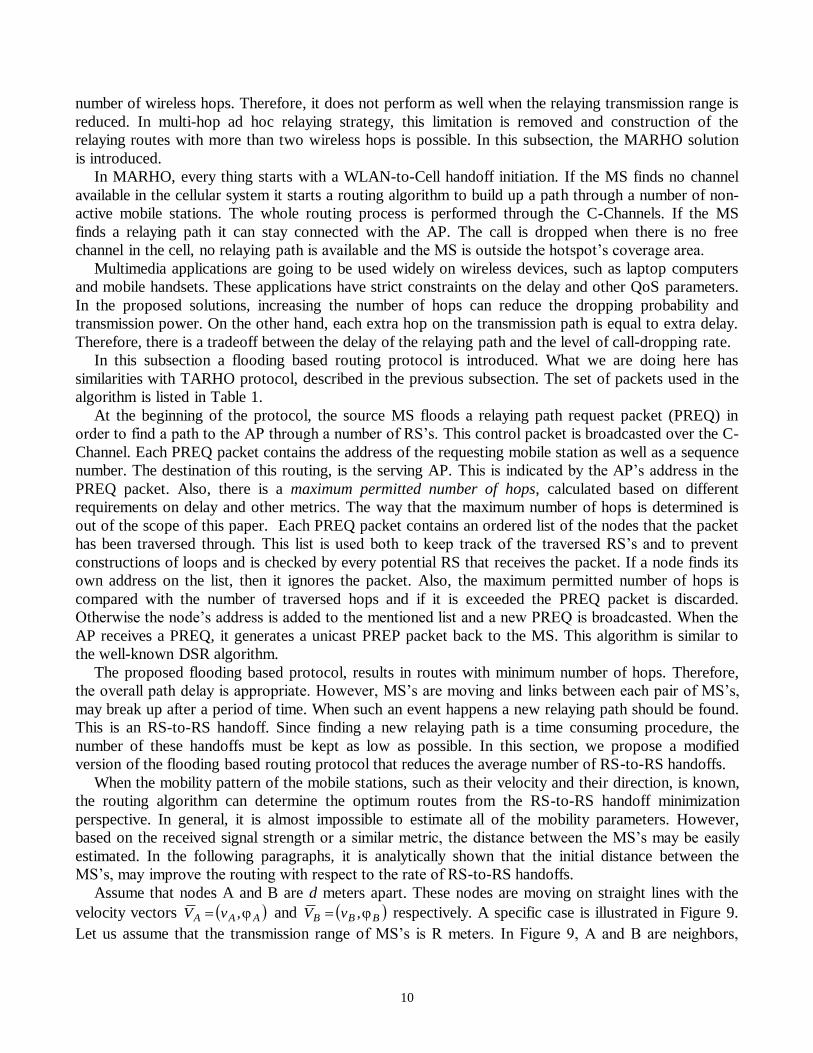
While TARHO can reduce the call-dropping rate dramatically, its performance is limited by the
10
number of wireless hops. Therefore, it does not perform as well when the relaying transmission range is
reduced. In multi-hop ad hoc relaying strategy, this limitation is removed and construction of the
relaying routes with more than two wireless hops is possible. In this subsection, the MARHO solution
is introduced.
In MARHO, every thing starts with a WLAN-to-Cell handoff initiation. If the MS finds no channel
available in the cellular system it starts a routing algorithm to build up a path through a number of non-
active mobile stations. The whole routing process is performed through the C-Channels. If the MS
finds a relaying path it can stay connected with the AP. The call is dropped when there is no free
channel in the cell, no relaying path is available and the MS is outside the hotspot’s coverage area.
Multimedia applications are going to be used widely on wireless devices, such as laptop computers
and mobile handsets. These applications have strict constraints on the delay and other QoS parameters.
In the proposed solutions, increasing the number of hops can reduce the dropping probability and
transmission power. On the other hand, each extra hop on the transmission path is equal to extra delay.
Therefore, there is a tradeoff between the delay of the relaying path and the level of call-dropping rate.
In this subsection a flooding based routing protocol is introduced. What we are doing here has
similarities with TARHO protocol, described in the previous subsection. The set of packets used in the
algorithm is listed in Table 1.
At the beginning of the protocol, the source MS floods a relaying path request packet (PREQ) in
order to find a path to the AP through a number of RS’s. This control packet is broadcasted over the C-
Channel. Each PREQ packet contains the address of the requesting mobile station as well as a sequence
number. The destination of this routing, is the serving AP. This is indicated by the AP’s address in the
PREQ packet. Also, there is a maximum permitted number of hops, calculated based on different
requirements on delay and other metrics. The way that the maximum number of hops is determined is
out of the scope of this paper. Each PREQ packet contains an ordered list of the nodes that the packet
has been traversed through. This list is used both to keep track of the traversed RS’s and to prevent
constructions of loops and is checked by every potential RS that receives the packet. If a node finds its
own address on the list, then it ignores the packet. Also, the maximum permitted number of hops is
compared with the number of traversed hops and if it is exceeded the PREQ packet is discarded.
Otherwise the node’s address is added to the mentioned list and a new PREQ is broadcasted. When the
AP receives a PREQ, it generates a unicast PREP packet back to the MS. This algorithm is similar to
the well-known DSR algorithm.
The proposed flooding based protocol, results in routes with minimum number of hops. Therefore,
the overall path delay is appropriate. However, MS’s are moving and links between each pair of MS’s,
may break up after a period of time. When such an event happens a new relaying path should be found.
This is an RS-to-RS handoff. Since finding a new relaying path is a time consuming procedure, the
number of these handoffs must be kept as low as possible. In this section, we propose a modified
version of the flooding based routing protocol that reduces the average number of RS-to-RS handoffs.
When the mobility pattern of the mobile stations, such as their velocity and their direction, is known,
the routing algorithm can determine the optimum routes from the RS-to-RS handoff minimization
perspective. In general, it is almost impossible to estimate all of the mobility parameters. However,
based on the received signal strength or a similar metric, the distance between the MS’s may be easily
estimated. In the following paragraphs, it is analytically shown that the initial distance between the
MS’s, may improve the routing with respect to the rate of RS-to-RS handoffs.
Assume that nodes A and B are d meters apart. These nodes are moving on straight lines with the
velocity vectors AAA vV , and BBB vV , respectively. A specific case is illustrated in Figure 9.
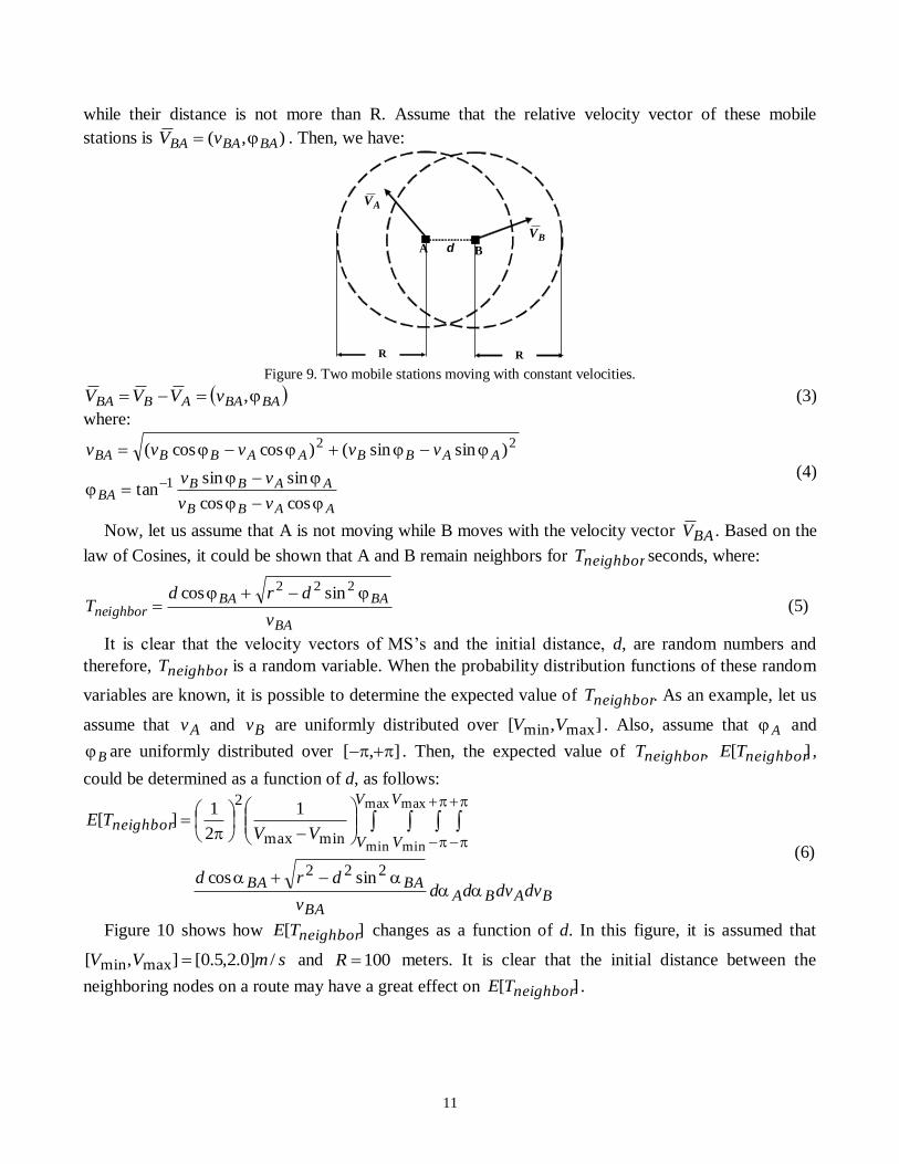
Let us assume that the transmission range of MS’s is R meters. In Figure 9, A and B are neighbors,
11
while their distance is not more than R. Assume that the relative velocity vector of these mobile
stations is ),( BABABA vV . Then, we have:
d A B
R R
AV
BV
Figure 9. Two mobile stations moving with constant velocities.
BABAABBA vVVV , (3)
where:
AABB
AABBBA
AABBAABBBA
vv
vv
vvvvv
coscos
sinsintan
)sinsin()coscos(
1
22
(4)
Now, let us assume that A is not moving while B moves with the velocity vector BAV . Based on the
law of Cosines, it could be shown that A and B remain neighbors for neighborT seconds, where:
BA
BABAneighbor
v
drdT
222 sincos (5)
It is clear that the velocity vectors of MS’s and the initial distance, d, are random numbers and
therefore, neighborT is a random variable. When the probability distribution functions of these random
variables are known, it is possible to determine the expected value of neighborT . As an example, let us
assume that Av and Bv are uniformly distributed over ],[ maxmin VV . Also, assume that A and
B are uniformly distributed over ],[ . Then, the expected value of neighborT , ][ neighborTE ,
could be determined as a function of d, as follows:
BABABA
BABA
V
V
V
Vneighbor
dvdvddv
drd
VVTE
222
minmax
2
sincos
1
2
1][
max
min
max
min (6)
Figure 10 shows how ][ neighborTE changes as a function of d. In this figure, it is assumed that
smVV /]0.2,5.0[],[ maxmin and 100R meters. It is clear that the initial distance between the
neighboring nodes on a route may have a great effect on ][ neighborTE .

12
Figure 11. Average of
neighborT as a function of d, based on
the path loss propagation model of (7).
Figure 10. ][ neighborTE as a function of d, based on the
analytical model of (6).
In the above discussion, it was assumed that an appropriate estimation of d is available. However,
this estimation could be obtained based on the received signal strength or similar means. Simulations
are employed in order to investigate the effect of the signal propagation on ][ neighborTE . In our
simulations, a log-normal path loss propagation model with shadow fading is assumed for the wireless
channel. This model is widely accepted and used in the literature [39-41]. Also it is assumed that the
RSS is sampled every samplingT seconds and each sample is expressed as:
][][log10][ kFkdnLPkRSS T (7)
where k is the time index, TP is the transmitted power, L is a constant signal power loss, and n is the
path loss exponent. Also, ][kF represents the shadow fading modeled as a zero mean Gaussian
random variable with standard deviation . The distance between the transmitter and the receiver is
][kd . Initial parameter settings of the simulations are illustrated in Table 2. Simulation results are
illustrated in Figure 11. In this figure, the simulated average of neighborT is shown as a function of d,
the initial distance between MS’s.
Table 2. Simulation parameter settings.
Parameter Value Parameter Value
TP 100 mWatt samplingT 0.01 Sec
N 3.7 DisconnectRSS -85 dBm
7 dB ],[ maxmin VV [0.5,2.5] m/sec
L 28.7 dB
Now, let us assume that we have almost no knowledge about the distribution of the velocities and
mobility directions. Assuming maxmin , VvvV BA , it can be shown that max2VvBA . The
maximum value, max2V , occurs when A and B are moving on opposing directions, where
BA , with their maximum velocities, maxV . Under these conditions and for any certain value
13
of d, nodes A and B remain connected for mint seconds, where:
maxmin
2V
dRt
(8)
It is clear that any increase in d results in smaller mint . In general, if A and B stay connected for t
seconds, we have:
mintt (9)
Therefore, to decrease the number of RS-to-RS handoffs, it is better to select RS’s that are close to each
other. Hence, it is better to find paths based on the number of hops but also the length of the links in the
routes should be considered.
Let us assume that in the original flooding based routing the PREQ packet is broadcasted with a
certain transmission power. This packet is then received by all adjacent mobile stations which are at
most L meters away which is less than the relaying transmission range. Reducing the transmission
power causes L to shrink and, hence, closer nodes are selected to build up a relaying path. The details
of the routing process are described in the following paragraphs.
At the beginning of the protocol, the source MS floods a relaying path request packet (PREQ) in
order to find a path to the AP through a number of RS’s. Let us assume that the relaying transmission
range is equal to ρ. The first PREQ packet is broadcasted with a certain level of power such that it
could be received only by those potential relay stations that are at most L meters away, where:
02 kL k (10)
After checking the list of the traversed nodes and comparing the number of hops with a certain
upper limit, each node rebroadcasts the received PREQ with the same transmission range, L. When the
PREQ packet reaches the AP, a PREP packet is unicasted to the MS and a relaying path is constructed
successfully.
This algorithm could fail even if a suitable relaying path does exist. Therefore, to alleviate this
problem we assume that a timer is employed in the requesting MS. This timer is initialized after the
first broadcasting of PREQ. Expiration of the timer is interpreted as a routing failure. If the routing
fails, the next round is started with a higher level of the transmission power. This time, the transmission
power is such that the PREQ packet could be received by nodes that are at most L2 meters away. In
other words, the mentioned distance is doubled to 12 k . This process continues until the routing is
successful or the transmission distance exceeds the relaying transmission range, ρ.
It worth mentioning that if the protocol starts with a very small value for L , then the system is faced
with a very long routing process. Finding a feasible path, which meets the delay constraints would be
less likely with smaller L ’s.
In the following section, the performance of the proposed TARHO and MARHO strategies is
studied through simulations. Furthermore, the efficiency of the modified routing solution, proposed for
MARHO, is studied and compared with the original routing method.
IV. Simulation Results
A large number of simulations have been performed to evaluate the performance of the proposed
methods. In the following, we will describe some of the most important ones. The mobility model,
which is introduced in the following subsection, is a modified version of the well-known random
waypoint mobility model [42].

14
A. Simulation Environment
An event-based simulator is developed to evaluate the performance of the proposed methods. It is
assumed that there is only one cell and one WLAN, as two circles, and the WLAN is located inside the
cell. The hotspot and cell radii are assumed to be 100 and 1000 meters respectively.
The MS’s are classified as either Inside or Outside ones, depending on their locations respect to the
hotspot. For each class of MS’s a random way point mobility model is used. Each MS moves from its
current position toward its random destination with a random velocity. The destination of an Inside MS
is selected outside the hotspot with a probability of outP while the destination of an Outside MS is
selected inside with a probability of inP . Inside MS’s velocity has a uniform distribution between IVmin
and IVmax while the velocity of the Outside MS’s is uniformly distributed between OVmin
and OVmax .
When an Inside MS arrives at its destination, it waits there for a random time uniformly distributed
between 0.0 and pauseT . With the parameter settings of Table 3, out of the 1000 of MS’s that were
simulated, about 325 of MS’s are inside the hotspot, in steady state. The distribution of MS’s over the
simulation area is illustrated in Figure 12(a). Furthermore, Figure 12(b) shows the location of the
hotspot inside the cellular system. Figure 13 illustrates how the system reaches stability.
Table 3. Initial parameter settings in the simulations.
Parameter Definition Value
R Cell radius 1000.0 meters
r Hotspot radius 100.0 meters Relaying transmission range 100.0 meters
Δ Original transition area’s width 10.0 meters
/1 Average call duration 240.0 seconds
N Number of cellular channels 56 channels
M Maximum number of connections served by the hotspot 36 active calls
inP Destination of an Outside MS is selected inside the hotspot with this
probability. 0.1
outP Destination of an Inside MS is selected outside the hotspot with this
probability. 0.35
],[ maxminII VV
The velocity of Inside MS’s is uniformly
distributed over this range. [0.5,2.0] m/sec
],[ maxminOO VV
The velocity of Outside MS’s is uniformly
distributed over this range.
[1.0,15.0]
m/sec
pauseT Inside MS’s waits at their destinations for a random
time uniformly distributed over ],0[ pauseT 300.0 seconds

15
(a)
(b)
Figure 12. (a) Distribution of MS’s over the simulation area, with logarithmic scale. (b) Location of the hotspot
inside the cellular system.
Figure 13. Stability in the number of nodes inside the hotspot.
New call generation rate is and new calls are generated based on a Poisson distribution. Call
duration is an exponentially distributed random variable. The average call duration is /1 . It is
assumed that the hotspot (WLAN) can serve M connections. Also, it is assumed that the cellular system
has N channels. Initial parameter setting which is used in the simulations is illustrated in Table 3. Some
of these parameters were used as variables in the simulations.
When an Inside (Outside) MS with an active connection moves outside (inside) the hotspot a
handoff is initialized. Rejected handoff requests are en-queued in order to wait for a free channel. It is
assumed that even Inside MS’s can be served by the cellular system. Therefore, there is no dropping
event when a Cell-to-WLAN handoff is being rejected.
Let us see what will happen when a WLAN-to-Cell handoff is rejected. In the LHO model, these
rejected requests are en-queued. In this case, when the distance between the MS and the AP is more
than an upper bound, r , the connection is dropped. In the TARHO model, when the rejected
request is en-queued, the MS finds an RS and through ad hoc relaying stays connected with its original
AP. The call is dropped when there is no free channel in the cell, there is no relaying path available,
and the distance between the MS and the AP is greater than r . En-queued handoff requests are
served in a first come first serve manner when at least one free channel is available in the cellular side.
In MARHO things are similar to the case of TARHO except that the relaying path may have more than
two hops. Each mobile station has a maximum permitted number of hops used as a constraint in the

16
routing protocol. This constraint is a random integer number between 2 and 10 generated at the
beginning of the simulation. Simulation results are presented in the following subsection.
B. Simulation Results
Dropping and blocking probabilities are the most important parameters influence the performance of
a wireless mobile communication system. The effect of ad hoc relaying on these parameters is
measured through the simulation and the simulation results are presented in this subsection.
Simulation results are shown in Figures 14 to 17. Figure 14 illustrates the dropping probability when
the average call duration is changed from 180 to 240 seconds. Blocking probabilities for the same
parameters are shown in Figure 15. The illustrated blocking probabilities are measured in the overall
hybrid system. In other words, when a new connection request is generated inside the hotspot and, for
some reasons, it is rejected by the WLAN service provider, the request is passed to the cellular side. If
the WLAN and the cell reject a new connection request then a blocking is occurred. When channel
reservation is used for dropping probability reduction, a number of channels are dedicated for the
handoff requests. This results in an increase in the blocking probability. The proposed relaying methods
reduce the dropping probability with almost no change in the blocking probability. Therefore, the
capacity of the hybrid system may be used more efficiently.
Figure 16 illustrates the dropping probability when the average call duration is 240 seconds while
the relaying transmission range is changing from 50 meters to 100 meters. It is clear from these figures
that TARHO has much lower dropping probabilities compared with the LHO method. Also, it is
obvious that the dropping probability is even lower when MARHO strategy is employed instead of
TARHO. It is clear from Figure 16 that using shorter transmission ranges would result in higher
dropping probabilities. However, due to the direct relation between the transmission range and
transmission power, shorter relaying transmission ranges are preferred. With shorter transmission
ranges, there will be smaller extension of the original coverage area. One straightforward way to reduce
the relaying transmission range with almost no increase in the dropping probability is to use a multi-
hop ad hoc relaying solution.
Figure 17 illustrates how the average number of hops on the relaying path is changed when the
relaying transmission range is changing from 50 to 100 meters. It is obvious from this figure that the
average number of hops increases when the relaying transmission range is decreased. In a real-time
environment, delay is one of the important parameters that must be taken into account. Increasing the
number of hops on a relaying path is equivalent with increasing the transmission delay. However,
increasing the transmission range is equal to increasing the transmission power. Therefore, based on the
system parameters such as the maximum required transmission power, the maximum permitted delay
and the dropping rate, the relaying transmission range must be determined.
Overall the simulation results prove that the proposed TARHO and MARHO methods are superior
to the traditional handoff strategies in terms of reducing the dropping probability in hybrid
WLAN/Cellular systems. Ad hoc relaying has previously been used for other purposes such as capacity
and/or coverage improvement and the same kind of handset capabilities can be employed in our
suggested method. Decision making between TARHO and MARHO is decision making between the
complexity and performance. While TARHO strategy is really simple, the performance and flexibility
of the MARHO method is higher.
The simulation results, related to the modified version of the MARHO routing strategy, are
illustrated in Figures 18 to 21. In these figures, the results related to the modified routing algorithm are
indicated by MARHO-M label.

17
Figure 14. Dropping Probability as a function of
average call duration. Figure 15. Blocking probability as a function of
average call duration.
Figure 16. Dropping probability as a function of
relaying transmission range.
Figure 17. Average path length in number of hops as a
function of relaying transmission range.
Figure 18. Dropping probabilities in LHO, MARHO and
MARHO-M.
Figure 19. Average Maximum Link Length as a function of
relaying transmission range.

18
Figure 20. Average number of RS-to-RS handoffs, as a
function of relaying transmission range.
Figure 21. Average number of RS-to-RS handoffs, as a
function of average call duration.
Figure 18 compares the dropping probability, when the simple flooding based algorithm, MARHO,
and its modified version, MARHO-M, are in use. For the case of MARHO-M the routing process starts
with 22L . It is clear from this figure that MARHO and MARHO-M have almost the same
dropping probabilities. In fact, MARHO could be considered as a special case of the MARHO-M
strategy. In Figure 19 it is shown how the average length of the longest link in the routes changes when
two different routing strategies are in use. As it is expected, MARHO-M results in shorter longest links.
This may result in a smaller number of RS-to-RS handoffs. It is illustrated in Figures 20 and 21 that
MARHO-M has smaller number of RS-to-RS handoffs.
A number of methods have been proposed in the literature for repairing a broken route in an ad hoc
network [43]. While it is really important to repair a broken path, it is always a good idea to keep the
number of RS-to-RS handoffs as low as possible. In MARHO strategy, relaying is employed under
critical conditions where a vertical handoff has been initiated by an active MS toward the cellular
system while the cellular system is fully occupied and we are facing with a connection drop. Most of
the times, a channel is released in the cellular side and the relaying is employed for only a short period
of time. Hence, with a smaller number of RS-to-RS handoffs, the need for a route repair is decreased
dramatically. However, the proposed solution could always be used beside the route repair strategies in
order to improve the overall behavior of the MARHO model.
The proposed MARHO-M is a generalization of the MARHO strategy. The simulation results show
that this generalized method, reduces RS-to-RS handoffs more than its mentioned predecessor.
Furthermore, from the dropping rate perspective, both proposed algorithms have an almost similar
performance.
V. Conclusions
Dropping probability is one of the important performance parameters in wireless communication
systems. In loosely coupled WLAN/Cellular systems the system administrator of the WLAN is
different from the cellular one. Therefore, dropping rate reduction by traditional methods such as using
reserved guard channels is not an easy task. In this paper, we suggested to use the ad hoc relaying for
reducing the dropping probability in a hybrid WLAN/cellular system. Dropping probability can reach

19
below an acceptable threshold, when the proposed TARHO and MARHO strategies are employed.
Based on simulations, we showed that by using MARHO, the relaying transmission range can be
reduced for a given dropping probability. Furthermore, a generalized routing strategy is proposed for
the MARHO solution. The proposed methods can also be used in tightly coupled hybrid networks.
While we proposed and evaluated the relaying method for a hybrid WLAN/Cellular system, the same
method is applicable in a multi-layered cellular system for vertical handoff. They can also be applied in
traditional single layer cellular systems for handoff between neighboring cells. For these networks, the
ad hoc relaying reduces the need for channel reservation. The proposed methods are supported by a set
of practical considerations, which make it possible to implement these algorithms. Simulation results
show the effectiveness of the suggested strategies.
References
[1] IEEE Standards Department, IEEE Draft Standard – Wireless LAN, IEEE Press, 1996.
[2] M.Rahnema, “Overview of the GSM System and Protocol Architecture”, IEEE Communications Magazine, April 1993.
[3] J.Cai, D.J.Goodman, “General Packet Radio Service in GSM”, IEEE Communications Magazine, Oct. 1997,
Pp 122-131.
[4] J.Korhonen, Introduction to 3G Mobile Communications, Artech House, 2nd
Edition, 2003. [5] A. Doufexi, et al. “Hotspot Wireless LANs to Enhance the Performance of 3G and Beyond Cellular
Networks”, IEEE Communications Mag. , PP 58-65 , July 2003.
[6] K.Ahmavaara, H.Haverinen, R.Pichna “Interworking Architecture Between 3GPP and WLAN Systems”, IEEE Communications Magazine, Pp 74-81, November 2003.
[7] D. Zhao, T.D. Todd, “Real-Time Traffic Support in Relayed Wireless Access Networks Using IEEE 802.11”,
IEEE Wireless Communications, April 2004, Pp 32-39, April 2004. [8] A.G.Spilling et al “Self-Organisation in Future Mobile Communications”, Electronics & Communication
Engineering Journal, Pp 133-147, June 2000.
[9] R.Fantacci, “Performance Evaluation of Prioritized Handoff Schemes in Mobile Cellular Networks”, IEEE
Trans. On Vehicular Technology, Vol. 49, No. 2, Pp. 485-493, 2000. [10] J.Misic, T.Y.Bun, “About the problem of hot-spots under adaptive admission control in wireless multimedia
networks”, Proceedings of IEEE WCNC, Pp 1238-1242, 1999.
[11] S.De, O.Tonguz, H.Wu, C.Qiao, “Integrated Cellular and Ad Hoc Relay (iCAR) Systems: Pushing the Performance Limits of Conventional Wireless Networks”, Proceedings of HICSS 2002, Pp 3899 -3906, 2002.
[12] T.Todd, D.Zhao, “Cellular CDMA Capacity in Hotspots with Limited Ad hoc Relaying”, Proceedings of
IEEE PIMRC 2003.
[13] J.H.Yap, X.Yang et al, “Position Assisted Relaying and Handover in Hybrid Ad hoc WCDMA Cellular Systems”, Proceedings of IEEE PIMRC 2002, Pp 2194-2198, Sept. 2002.
[14] G.N. Aggelou, R. Tafazolli, “On the Relaying Capability of Next-Generation GSM Cellular Networks”,
Proceedings of IEEE Personal Communications, Pp 40-47, Feb. 2001. [15] T. Rouse, S.McLaughlin, H.Haas, “Coverage-Capacity Analysis of Opportunity Driven Multiple Access
(ODMA) in UTRA TDD”, Proceedings of the International Conf. On 3G Mobile Communication Technologies,
Pp 252 -256, 2001. [16] M. He, T.D.Todd, D. Zhao, V. Kezys, “Ad Hoc Assisted Handoff for Real-time IEEE 802.11 Infrastructure
WLANs”, Proceedings of the IEEE WCNC 2004.
[17] Y.D.Lin, Y.C.Hsu, “Multihop Cellular: A New Architecture for Wireless Communications”, Proceedings of
Infocomm 2000, Pp 1273-1282, 2000. [18] H.C.Chao, C.Y. Huang, “Micro-Mobility Mechanism for Smooth Handoffs in an Integrated Ad-Hoc and
Cellular IPv6 Network Under High-Speed Movement”, IEEE Trans. On Vehicular Technology, Vol. 52, No. 6,
Pp1576-1593, 2003.

20
[19] V. Sreng, H. Yanikomeroglu, D.D. Falconer, “Relayer Selection Strategies in Cellular Networks with Peer-
to-Peer Relaying”, Proceedings of the IEEE VTC’F03, October 2003.
[20] D.B.Johnson and D.A.Maltz. “Dynamic Source Routing in Ad Hoc Wireless Networks”, Mobile
Computing, edited by Tomasz Imielinski and Hank Korth, Chapter 5, pages 153-181, Kluwer Academic Publishers, 1996.
[21] C.E.Perkins and E.M.Royer. “Ad hoc On-Demand Distance Vector Routing”, Proceedings of the 2nd IEEE
Workshop on Mobile Computing Systems and Applications, New Orleans, LA, February 1999, pp. 90-100. [22] C.E.Perkins, P.Bhagwat, “Higly Dynamic Destination-Sequenced Distance Vector (DSDV) for Mobile
Computers”, Proceedings of the SIGCOMM 1994 Conference on Communications Architectures, Protocols and
Applications, Aug 1994, pp 234-244. [23] J.Gomez, A.T.Campbell, M.Naghshineh, C.Bisdikian “Power-aware Routing in Wireless Packet Networks”,
Proceedings sixth IEEE International Workshop on Mobile Multimedia Communications (MoMuC'99), San
Diego, California, November 1999.
[24] Q.Li, J.Aslam, D.Rus, “Online power-aware routing in wireless Ad-hoc networks”, Proceedings of the 7th annual international conference on Mobile computing and networking, Rome, Italy, Pages: 97 – 107, 2001.
[25] C.Zhu, M.S.Corson, “QoS routing for mobile ad hoc networks”, Proceedings Of Infocom 2002, Pp 958-967,
2002. [26] R.Ramanathan, J.Redi, “A Brief Overview of Ad Hoc Networks: Challenges and Directions”, IEEE
Communications Magazine, May 2002, Pp 20-22.
[27] S.Chakrabarti, A.Mishra, “QoS Issues in Ad Hoc Wireless Networks”, IEEE Communications Magazine, Feb. 2001, Pp 142-148.
[28] P.Khadivi, S.Samavi, T.D.Todd, H.Saidi, “Multi-Constraint QoS Routing Using a New Single Mixed
Metric”, Proceedings of IEEE International Conference on Communications (ICC 2004), Vol. 4 , 20-24 June
2004, Paris, France, Pages:2042 – 2046. [29] Q.Zhang, et al. “Efficient Mobility Management for Vertical Handoff between WWAN and WLAN”, IEEE
Comm. Mag., Nov. 2003, Pp 102-108.
[30] J.W.Florolu, et al “Seamless Handover in Trestrial Radio Access Networks: A Case Study”, IEEE Comm. Mag., Nov. 2003, Pp 110-116.
[31] K.Pahlavan, P. Krishnamurthy, et al. “Handoff in Hybrid Mobile Data Networks”, IEEE Personal
Communications, April 2000, Pp 34-47.
[32] M.Portoles, et al. “IEEE 802.11 Link-Layer Forwarding for Smooth Handoff”, Proceedings of IEEE PIMRC 2003, Pp 1420-1424.
[33] Y.Pan, et al. “An End-to-End Multipath Smooth Handoff Scheme for Stream Media”, IEEE JSAC, May
2004. [34] D.Tandjaoui, et al. “Performance Enhancement of Smooth Handoff in Mobile IP by Reducing Packets
Disorder”, Proceedings of IEEE ISCC 2003.
[35] P.Khadivi, T.D.Todd, D.Zhao, “Handoff Trigger Nodes for Hybrid IEEE 802.11 WLAN/Cellular Networks”, Proceedings of the First International Conference on Quality of Service in Heterogeneous
Wired/Wireless Networks (Qshine 2004), Dallas, USA, 2004.
[36] P.Khadivi, T.D.Todd, S.Samavi, H.Saidi, D.Zhao, “Mobile Ad Hoc Relaying in Hybrid WLAN/Cellular
Systems for Dropping Probability Reduction”, Proceedings of the 9th CDMA International Conference (CiC 2004), Korea, October 25-28, 2004.
[37] H.Wu, S.De, C.Qiao, E.Yanmaz, and O.Tonguz, "Handoff Performance of The Integrated Cellular and Ad
Hoc Relaying (iCAR) System", in ACM Wireless Networks (WINET), Vol. 11, No. 6, November, 2005. [38] C. Prehofer, C.Bettstetter, “Self-Organization in Communication Networks: Principles and Design
Paradigms”, IEEE Communications Magazine, Pp 78-85, July 2005.
[39] A.H.Zahran and B.Liang, “Performance Evaluation Framework for Vertical Handoff Algorithms in Heterogeneous Networks”, Proc. of the IEEE Int. Conf. on Communications (ICC), Vol. 1, Pp 173-178, 2005.
[40] A.Majlesi and B. Khalaj, “An Adaptive Fuzzy Logic Based Handoff Algorithm for Hybrid Networks”,
Proc. of the 6th IEEE International Conference on Signal Processing, Vol. 2, Pp 1223-1228, 2002

21
[41] N.Zhang and J.M.Holtzman, “Analysis of handoff algorithms using both absolute and relative
measurements”, IEEE Trans. on Vehicular Technology, Vol. 45, No. 1, Pp 174-179, Feb. 1996.
[42] C.Bettstetter, C.Wagner “The Spatial Node Distribution of the Random Waypoint Mobility Model”,
Proceedings of WMAN 2002, Pp 41-58, 2002. [43] S. Chakrabarti, A. Mishra “QoS Issues in Ad-Hoc Wireless Networks”, IEEE Communications Mag., Feb.
2001, 142-148.