Protective Relaying Principkes and Applications - J. Lewis Blackburn
559
Transcript of Protective Relaying Principkes and Applications - J. Lewis Blackburn


Protective ~elay i rrg Principles and Appli@om
/ Second Edition
J. Lewis Blackburn Bothell, Washington
M A R C E L
MARCEL DEKKER, INC. N EW YORK . BASEL. HONC KONC

Introduction and General Philosophies
1.1 INTRODUCTION AND DEFINITIONS
What is a relay; more specifically, what is a protective relay? The Institute of Electrical and Electronic Engineers (IEEE) defines a relay as “an electric device that is designed to respond to input conditions in a prescribed manner and, after specified conditions are met, to cause contact operation or similar abrupt change in associated electric control circuits.” A note amplifies: “In- puts are usually electric, but may be mechanical, thermal, or other quantities or a combination of quantities. Limit switches and similar simple devices are not relays” (IEEE C37.90).
Relays are used in all aspects of activity: the home, communication, transportation, commerce, and industry, to name a few. Wherever electricity is used, there is a high probability that relays are involved. They are used in heating, air conditioning, stoves, dishwashers, clothes washers and dryers, elevators, telephone networks, traffic controls, transportation vehicles, au- tomatic process systems, robotics, space activities, and many other applications.
In this book we focus on one of the more interesting and sophisticated applications of relays, the protection of electric power systems. The IEEE defines a protective relay as “a relay whose function is to detect defective
1

2 Chapter 1
lines or apparatus or other power system conditions of an abnormal or dan- gerous nature and to initiate appropriate control circuit action” (IEEE 100).
Fuses are also used in protection. IEEE defines a fuse as “an over- current protective device with a circuit-opening fusible part that is heated and severed by the passage of the overcurrent through it” (IEEE 100).
Thus, protective relays and their associated equipment are compact units of analog, discrete solid-state components, operational amplifiers, dig- ital microprocessor networks connected to the power system to sense prob- lems. These are frequently abbreviated simply as relays and relay systems. They are used in all parts of the power system, together with fuses, for the detection of intolerable conditions, most often faults.
Protective relaying, commonly abbreviated “relaying,” is a nonprofit, nonrevenue-producing item that is not necessary in the normal operation of an electrical power system until a fault-an abnormal, intolerable situation-occurs.
A primary objective of all power systems is to maintain a very high level of continuity of service, and when intolerable conditions occur, to minimize the outage times. Loss of power, voltage dips, and overvoltages will occur, however, because it is impossible, as well as impractical, to avoid the consequences of natural events, physical accidents, equipment failure, or misoperation owing to human error. Many of these result in faults: in- advertent, accidental connections or “flashovers” between the phase wires or from the phase wire(s) to ground.
Natural events that can cause short circuits (faults) are lightning (in- duced voltage or direct strikes), wind, ice, earthquake, fire, explosions, fall- ing trees, flying objects, physical contact by animals, and contamination. Accidents include faults resulting from vehicles bitting poles or contacting live equipment, unfortunate people contacting live equipment, digging into underground cables, human errors, and so on. Considerable effort is made to minimize damage possibilities, but the elimination of all such problems is not yet achievable.
A dramatic illustration of the need and importance of power system protection is shown in Fig. 1.1. This spectacular lightning strike occurred over Seattle during a storm on July 31, 1984, and in a region where lightning is infrequent. The isokeraunic charts for this area of the Pacific Northwest indicate that the probability of storm days when thunder is heard is 5 or fewer per year (Electrical Transmission and Distribution Reference Book, 4th ed., Westinghouse Electric Cop., East Pittsburgh PA, 1964). Although some 12,000 homes lost power during this storm, no major damage nor prolonged outages were experienced by the local utilities. Fortunately, light- ning protection and many relays operated to minimize the problems.

Introduction and General Philosophies 3
FIGURE 1.1 power system protection (Greg GilberVSeattle Times photo).
Lightning over Seanle-a vivid illustration of the importance of
Most faults in an electrical utility system with a network of overhead lines are one-phase-to-ground faults resulting primarily from lightning- induced transient high voltage and from falling trees and tree limbs. In the overhead distribution systems, momentary tree contact caused by wind is another major cause of faults. Ice, freezing snow, and wind during severe storms can cause many faults and much damage. These faults include the following, with very approximate percentages of occurrence:
Single phase-to-ground: 70-80% Phase-to-phase-to ground 17-10%
Three-phase: 3-2%
Series unbalances, such as a broken conductor or a blown fuse, are not too common, except perhaps in the lower-voltage system in which fuses are used for protection.
Phase-to-phase: 10-8%
4 Chapter 1
Fault occurrence can be quite variable, depending on the type of power system (e.g., overhead versus underground lines) and the local natural or weather conditions.
In many instances, the flashover caused by such events does not result in permanent damage if the circuit is interrupted quickly. A common practice is to open the faulted circuit, permit the arc to extinguish naturally, and then reclose the circuit. Usually, this enhances the continuity of service by caus- ing only a momentary outage and voltage dip. Typical outage times are in the order of 112 to 1 or 2 min, rather than many minutes and hours.
System faults usually, but not always, provide significant changes in the system quantities, which can be used to distinguish between tolerable and intolerable system conditions. These changing quantities include over- current, over- or undervoltage power, power factor or phase angle, power or current direction, impedance, frequency, temperature, physical movements, pressure, and contamination of the insulating quantities. The most common fault indicator is a sudden and generally significant increase in the current; consequently, overcurrent protection is widely used.
Protection is the science, skill, and art of applying and setting relays or fuses, or both, to provide maximum sensitivity to faults and undesirable conditions, but to avoid their operation under all permissible or tolerable conditions. The basic approach throughout this book is to define the tolerable and intolerable conditions that may exist and to look for definite differences (“handles”) that the relays or fuses can sense.
It is important to recognize that the “time window” of decision in power system protection is very narrow, and when faults have occurred, a recheck for verification, or a decision-making procedure that involves ad- ditional time, is not desirable. It is vital (1) that a correct decision be made by the protective device as to whether the trouble is intolerable and, thus, demands quick action, or whether it is a tolerable or transient situation that the system can absorb; and (2) that, if necessary, the protective device op- erate to isolate the trouble area quickly and with a minimum of system disturbance. This trouble time may be, and often is, associated with high extraneous “noise,” which must not “fool” the device or cause incorrect operation.
Both failure to operate and incorrect operation can result in major system upsets involving increased equipment damage, increased personnel hazards, and possible long interruption of service. These stringent require- ments with serious potential consequences tend to make protection engineers somewhat conservative. One of the advantages of the modem solid-state relays is that they can check and monitor themselves to minimize equipment problems as well as to provide information on the events that resulted in triggering their operation.

introduction and General Philosophies 5
Problems can and do occur in protective equipment; nothing is perfect. To minimize the potential catastrophic problems that can result in the power system from a protection failure, the practice is to use several relays or relay systems operating in parallel. These can be at the same location (primary backup), at the same station (local backup), or at various remote stations (remote backup). All three are used together in many applications. In higher- voltage power systems this concept is extended by providing separate current or voltage, or both measuring devices, separate trip coils on the circuit breakers, and separate tripping battery sources.
The various protective devices must be properly coordinated such that the primary relays assigned to operate at the first sign of trouble in their assigned protective zone operate first. Should they fail, various backup sys- tems must be available and able to operate to clear the trouble. An adequate, high-protection redundancy capability is very important.
1.2 TYPICAL PROTECTIVE RELAYS AND RELAY SYSTEMS
A typical logic representation of relay is shown in Fig. 1.2. The components can be electromechanical, solid-state, or both. The logic functions are quite
-general, so that in any particular unit they may be combined or, on occasion, not required.
Specific designs and features vary widely with application require- ments, different manufacturers, and the time period of the particular design. Originally, all protective relays were of the electromechanical type, and these are still in wide use, hut solid-state designs are now more common. Although this trend continues, and is widespread, it may be a long time before elec- tromechanical devices are completely replaced.
The protection principles and fundamentals are essentially unchanged with solid-state relays, as is the protection reliability. However, solid- state relays provide higher accuracy, reduced space, lower equipment and installation costs, give wider application and setting capabilities, plus various other desirable supplemental features. These include control logic, data acquisition, event recording, fault location, remote setting, and self-
FIGURE 1.2 Logic representation of electric relays.


Introduction and General Philosophies 7
FIGURE 1.4 Typical relay protection for backup protection of two 500-kV transmission lines using electromechanical protective relays. (Courtesy of Georgia Power Company.)
<
FIGURE 1.3 Typical solid-state microprocessor relays for power system pro- tection: (a-c) Rack-type mounting: (a) three-phase and ground distance, (b) segregated-phase comparison system, (c) phase and ground distance with pilot capabilities. (d,e) "FlexitesWype cases for panel mounting: (d) three- phase and ground overcurrent, (e) same as (c). (Courtesy of ABB PowerT&D Company. Coral Springs, FL.)

8 Chapter 1
FIGURE 1.5 Typical relay panel for the protection of a cogenerator intertie, using solid-state relays. (Courtesy of Harlo Corporation, Control Panel Divi- sion, and Basler Electric.)
monitoring and cliccking. T h features will vary with different types and manufacturers.
For those i i i i t familiar with protective relays, several modern relays are illustrated in Figs. 1.3 and 1.6. Electromechanical relays iiioittited on a panel arc shown in Fig. 1.4, and provide backup protcction for two 500-kV trans- iiiission lines.
Three sections of a control-protection switchboard for 500-kV circuits are shown in Fig. 1.5. This illustrates the combination of electromechaiiical and solid-state relays. Solid-state relays are commonly rack-mounted, a s shown. Doors provide acccss to the removable printed-circuit boards and test-adjustmerit facilities.

Introduction and General Philosophies 9
FIGURE 1.6 Typical microprocessor distance relays for single-pole tripping at 500 kV. (Courtesy of Schweitrer Engineering Laboratories, Inc.. Pullman, WA.)
The fundamental characteristics of relay designs necessary to undcr- stand the applications are outlined in Chapter 6 and are augmented as re- quired in subse,quent chapters.
Two panels of solid-state relays during factory testing are illustrated in Fig. 1.6. The front covers have becn removed. Thc right panel has one of the relay units pulled out.
1.3 TYPICAL POWER CIRCUIT BREAKERS
Protective relays provide the “brains” to sense irouble, but as low-energy devices, they are not able to open and isolate the problcm area of the power system. Circuit breakers and various types of circuit interrupters, including niotor cantactors and motor controllers, arc used fnr this and provide the “muscle” for fault isolation. Thus, protective relays and circuit breaker- interrupting devices are a “team,” both necessary for the prompt isolation of a trouhle area or damaged equipment. A protective relay without a circuit

10 Chapter 1
breaker has no basic value except possibly for alarm. Similarly, a circuit breaker without relays has minimum value, that being for manually ener- gizing or deenergizing a circuit or equipment.
Typical circuit breakers used to isolate a faulted or damaged area are shown in Figs. 1.7 and 1.8. Figure 1.7 shows a long row of three-phase 115- kV oil circuit breakers with pneumatic controls in an outdoor substation. These are known as dead-tank breakers; the tank or breaker housing is at ground potential. Toroidal wound-bushing current transformers are mounted in the pods just under the fluted porcelain insulators at the top of the tank. This general type is in wide use in many different designs and variations. The media employed for circuit interruption include air, air blast, com- pressed air, gas, and vacuum in addition to oil.
Figure 1.8 shows a 500-kV live-tank circuit breaker. Here the inter- rupting mechanisms and housing is at the high-voltage level and insulated from ground through the porcelain columns. The current transformers are mounted on separate porcelain columns, as shown at the left of each phase breaker.
Dead-tank breakers, such as those illustrated in Fig. 1.7, usually have a single trip coil that initiates simultaneous opening of all three-phase
FIGURE 1.7 Row of typical three-phase 115-kV oil circuit breakers. The pneu- matic-operating mechanism is visible within the open cabinet. (Courtesy of Puget Sound Power and Light Company.)


12 Chapter 1
to one less severe from a system stability standpoint, either double-phase or single-phase.
Because most transmission-line faults are transient single-line-to- ground type, opening only the faulted phase would clear it. With a transient fault, such as that resulting from lightning-induced overvoltage, immediate reclosing of the open, faulted phase would restore three-phase service. Known as single-pole tripping, this tends to reduce the shock on the power system. It is discussed further in Chapters 13 and 14.
As indicated above, at the lower voltages, the circuit breaker (inter- rupter) and relays frequently are combined into a single-operating unit. The circuit-breaker switches commonly installed in the service entrance cabinet in modem residential homes and commercial buildings are typical examples. In general, this type of arrangement is used up through 480-600 V. Pri- marily, the protection is overcurrent, although overvoltage may be included. The low accuracy and difficulties of calibration and testing have resulted in a wider application of solid-state technology in these designs. Because the relay units and breaker are together physically and the voltage exposure level is low, the problems of extraneous voltages and noise that affect solid-state designs are minimized.
1.4 NOMENCLATURE AND DEVICE NUMBERS
The nomenclature and abbreviations used generally follow common practice in the United States. The functions of various relays and equipment are identified by the ANSMEEE standardized device function numbers (IEEE C37.2). A brief review is in order.
The phases of the three-phase system are designated as A, B, C or a, b, c, rather than 1, 2, 3, also used in the United States, or r, s, t , used in Europe. 1, 2, 3 is avoided because 1 also designates positive sequence, and 2, negative sequence. Letters avoid possible confusion. Capital letters are used on one side of wye-delta transformer banks, with lower case letters on the other side. Although normally not followed in practice, this empha- sizes that there is a phase shift and voltage difference across the transformer bank.
Device numbers with suffix Letter(s) provide convenient identification of the basic functions of electrical equipment, such as circuit breakers, re- lays, switches, and so on. When several units of the same type of device are used in a circuit or system, a number preceding the device number is used to differentiate between them. Letters following the device number provide additional information on the application, use, or actuating quanti- ties. Unfortunately, the same letter may be used with quite different con- notations or meanings. Normally, this will be clear from the use.

Introduction and General Philosophies 13
Letters and abbreviations frequently used include the following:
A ac or AC B BP BT C cc cs CT CCVT D dc or DC E F G* GND, Gnd H L M MOC MOD MOS N* NC NO 0 P PB PF R S T TC U V
Alarm Alternating current Bus, battery, blower Bypass Bus tie Current, close, control, capacitor, compensator, case Closing coil, coupling capacitor, carrier current Control switch, contactor switch Current transformer Coupling capacitor voltage device Down, direct, discharge Direct current Exciter, excitation Field, feeder, fan Ground, generator Ground Heater, housing Line, lower, level, liquid Motor, metering Mechanism-operated contact Metal oxide protective device Motor-operated switch Neutral, network Normally closed Normally open Open Power, pressure Pushbutton Power factor Raise, reactor Speed, secondary, synchronizing Transformer, trip Trip coil Up, unit Voltage, vacuum
*N and G (or n and g) are used in circuits involving ground. A convention that is common but not standardized is the use of G when a relay is connected to a CT in the grounded neutral circuit, and N when connected in the neutral of three wye-connected CTs. Similar usage is applied to voltage.

14 Chapter 1
VAR Reactive power VT Voltage transformer W Watts, water x, y, z Auxiliary relays
Device numbers frequently used are listed below. A complete list and definitions are given in Standard IEEE C37.2.
1. Master element: normally used for hand-operated devices. A common use is the spring-return-to-center control switch for cir- cuit breakers, where the switch contacts are lOlT (trip), lOlc (close), lOlSC (closed when turned to close and remains closed when released, opens when turned to trip and remains open when released). When several breakers are involved, they are identified by 101, 201, 301, and so on. Time-delay starting or closing relay: except device functions 48, 62, and 79
2.
3. Checking or interlocking relay 4. Master contactor 5. Stopping device 6. Starting circuit breaker 7. Rate-of-rise relay 8. Control power-disconnecting device 9. Reversing device
10. Unit sequence switch 11. Multifunction device 12. Overspeed device 13. Synchronous-speed device 14. Underspeed device 15. Speed- or frequency-matching device 17. Shunting or discharge switch 18. Accelerating or decelerating device 19. Starting-to-running transition contactor 20. Electrically operated valve 21. Distance relay 22. Equalizer circuit breaker 23. Temperature control device 24. Voltshertz relay 25. Synchronizing or synchronism-check device 26. Apparatus thermal device 27. Undervoltage relay 28. Flame detector 29. Isolating contactor

Introduction and General Philosophies 15
30. Annunciator relay 31. Separate excitation device 32. Directional power relay 33. Position switch 34. Master sequence device 36. 37. Undercurrent or underpower relay . 38. Bearing protective device 39. Mechanical conduction monitor 40. Field relay 41. Field circuit breaker 42. Running circuit breaker 43. 44. Unitlsequence starting relay 45. Atmospheric condition monitor 46. Reverse-phase or phase-balance relay 47. Phase-sequence voltage relay 48. Incomplete-sequence relay 49. 50. Instantaneous overcurrent 51. ac time overcurrent relay 52.
Polarity or polarizing voltage device
Manual transfer or selector device
Machine or transformer thermal relay
ac circuit breaker: mechanism-operated contacts are: a. 52a, 52aa: open when breaker cantacts are open, closed
b. 52b, 52bb: closed when breaker contacts are open, open
52aa and S2bb operate just as mechanism moiion starts; known as high-speed contacts Exciter or dc generator relay
when breaker contacts are closed
when breaker contacts are closed.
53. 55. Power factor relay 56. Field application relay 57. Short-circuiting or grounding device 58. Rectification failure relay 59. Overvoltage relay 60. 62. 63. Pressure switch 64. Ground detector relay 65. Governor 66. Notching or jogging device 67. Ac directional overcurrent relay 68. Blocking relay
Voltage or current balance relay Time-delay stopping or opening relay
16
69. Permissive control device 70. Rheostat 71. Level switch 72. Dc circuit breaker 73. Load-resistor contactor 74. Alarm relay 76. Dc overcurrent relay 77. Telemetering device 78. 79. ac-reclosing relay 80. Flow switch 81. Frequency relay 82. Dc-reclosing relay 83. 84. Operating mechanism 85. 86. Lockout relay 87. Differential protective relay 88. 89. Line switch 90. Regulating device 91. Voltage directional relay 92. 93. Field-changing contactor 94. Tripping or trip-free relay
Phase-angle measuring or out-of-step protective relay
Automatic selective control or transfer relay
Carrier or pilot-wire receiver relay
Auxiliary motor or motor generator
Voltage and power directional relay
1.5 TYPICAL RELAY AND CIRCUIT BREAKER CONNECTIONS
Chapter 1
Protective relays using electrical quantities are connected to the power sys- tem through current (CT) or voltage (VT) transformers. These input devices or instrument transformers provide insulation from the high-power system voltages and reduce the magnitudes to practical secondary levels for the relays. An important element of the protection system, these units art dis- cussed in Chapter 5. In circuit schematics and diagrams they are represented as shown in Fig. 1.9. This diagram shows a typical “one-line” ac schematic and a dc trip circuit schematic.
The protective relay system is connected to the ac power system through the current transformers commonly associated with the circuit breaker and, if necessary, to the voltage transformers. These are shown con- nected to the station ac bus, but often at the higher voltages the voltage devices are connected to the transmission line. The circuit breaker is des-

Introduction and General Philosophies
ac Bus C u r r e n t Transformers ( C T ’ s )
C i r c u i t B r e a k e r
a c Protected C i r c u i t
17
Pro tec t ive R e l a y or system
Voltage Transformer (VTI (op t iona l l
POS. N e g .
d c S t a t i o n B a t t e r y
FIGURE 1.9 Typical single-line ac connections of a protective relay with its dc trip circuit. The CS seal in t he unit is not required with solid-state units and lower-trip circuit currents with modern circuit breakers.
ignated as device 52 following the ANSIAEEE device number system (IEEE C37.2).
In the dc schematic the contacts are always shown in their deenergized position. Thus, when the circuit breaker is closed and in service, its 52a contact is closed. When a system fault operates the protective relay, its output contact closes to energize the circuit breaker trip coil 52T, which functions to open the breaker main contacts and deenergize the connected power circuit.
The electromechanical relay contacts basically are not designed to in- terrupt the circuit breaker trip coil current, so an auxiliary dc-operated unit designed CS (contactor switch) was used to “seal-in” or bypass the protec- tive relay contacts as shown. When the circuit breaker opens, the 52a switch will open to deenergize the trip coil 52T. The interruption of the fault by the circuit breaker will have opened the protective relay contacts before the 52a contact opens. This CS unit is not required with solid-state relays.
The various power-interrupting devices are operated either by the over- current that passes through them during a fault, or by a dc-operated trip coil, such as that shown in Fig. 1.9. The first types are designated as series trip, direct acting, direct release, indirect release, and overcurrent release. Usually,

18 Chapter 1
these have built-in overcurrent relay units that determine the level of the ac current at and above which their contacts will open. All of these types are used at the lower-voltage level of the power system.
At the higher power system voltages each station at which circuit breakers are installed has a station battery to supply direct current to the breaker trip coils, the control and protective relay circuits as required, emer- gency alarms and lighting, and so on. In the United States this is generally 125-V dc; 250-V dc is used in some large power stations, and 48-V dc is
Pr imary BUS
current A B C TranSf.
Voltage For
VT'S When Appl icable Secondary voltages For Phase R e l a y When Requi red
FiGunE 1.10 Typical three-phase ac connections of a set of phase and ground relays for the protection of an ac power system. The relays may be separate, as shown, or combined together in one unit.

Introduction and General Philosophies 19
often used for electronic and solid-state devices. This dc supply is another vital part of the protection system and requires careful attention and main- tenance for high system and protection reliability.
Many protective relays are packaged as individual phase and ground units, so for complete phase- and ground-fault protection, four units are commonly used. Typical three-phase ac connections for a set of relays and their associated current and voltage transformers are shown in Fig. 1.10
1.6 BASIC OBJECTIVES OF SYSTEM PROTECTION
The fundamental objective of system protection is to provide isolation of a problem area in the system quickly, such that as much as possible of the rest of the power system is left to continue service. Within this context, there are five basic facets of protective relay application.
Before discussing these it should be noted that the use of the term “protection” does not indicate or imply that the protection equipment can prevent trouble, such as faults and equipment failures. It cannot anticipate trouble. The protective relays act only after an abnormal or intolerable con- dition has occurred, with sufficient indication to permit their operation. Thus protection does not mean prevention, but rather, minimizing the duration of the trouble and limiting the damage, outage time, and related problems that may otherwise result.
The five basic facets are:
1. Reliability: assurance that the protection will perform correctly 2. Selectivity: maximum continuity of service with minimum sys-
3. Speed of operation: minimum fault duration and consequent
4. Simplicity: minimum protective equipment and associated cir-
5. Economics: maximum protection at minimal total cost
Because these are the underlying foundation of all protection, further
tem disconnection
equipment damage
cuitry to achieve the protection objectives
discussion is in order.
1.6.1 Reliability
Reliability has two aspects: dependability and security. Dependability is de- fined as “the degree of certainty that a relay or relay system will operate correctly” (IEEE C37.2). Security “relates to the degree of certainty that a relay or relay system will not operate incorrectly” (IEEE C37.2). In other words, dependability indicates the ability of the protection system to perform

20 Chapter 1
correctly when required, whereas security is its ability to avoid unnecessary operation during normal day-after-day operation, and faults and problems outside the designated zone of operation. There is often a very fine line between the tolerable transients that the power system can operate through successfully, and those, such as light faults, that may develop and result in a major problem if not quickly isolated. Thus, the protection must be secure (not operate on tolerable transients), yet dependable (operate on intolerable transients and permanent faults). It is these somewhat conflicting require- ments, together with the speculation of what trouble may occur, when, and where, that help make power system protection a most-interesting technical science and art.
Dependability is easy to ascertain by testing the protection system to assure that it will operate as intended when the operating thresholds are exceeded. Security is more difficult to ascertain. There can be almost an infinite variety of transients that might upset the protective system, and pre- determination of all these possibilities is difficult or impossible.
Manufacturers often use elaborate power system simulations, comput- ers, and sometimes staged fault tests on energized power systems to check both dependability and security. The practical and best answer to both se- curity and dependability is the background experience of the designers, con- firmed by field experience. Thus, actual in-service installations provide the best and final laboratory. This should only confirm the reliability, not be used basically for the development.
As a generality, enhancing security tends to decrease the dependability, and vice versa. As an illustration, the single relay trip contact shown in Fig. 1.9 represents high dependability, but it has the potential of being acciden- tally closed by unanticipated transients or human error, and, thereby, result in an undesired operation. To minimize this potential problem, a second relay, such as a fault detector, can be used with its operating contact in series in the dc trip circuit. Now both contacts must close to trip the circuit breaker, which should occur for intolerable conditions or faults. This has increased security, for it is less likely that extraneous transients or problems would cause both relays to operate simultaneously. However, the dependability has been decreased, for it now requires two relays to operate correctly. This arrangement is used, because the dependability is still quite high, together with improved security.
Security is thus very important (as is dependability), as relays are con- nected for their lifetime to the power system as “silent sentinels,” “wait- ing” for intolerable conditions and experiencing all the transients and ex- ternal faults not in their operating zone. The hope always is that there will be no faults or intolerable conditions; hence, no occasion for the relays to operate. Fortunately, there are relatively few faults, on average, in a power

Introduction and General Philosophies 21
system. It is estimated that, in general, the cumulative operating time (the times the relay is sensing and operating for an internal fault) during a relay’s lifetime averages on the order of seconds to a few minutes, depending on the speed of the particular relay type. This contrasts dramatically with a life of over 30 years for many electromechanical relays. Therefore, relays ba- sically do not wear out from operations-indeed, more wear, as such, will occur from maintenance testing and similar use.
Similar experience occurs with solid-state relays, except that because of the still rapidly changing technology, the lifetime of many of these relays will probably be much shorter.
In general, experiences in power systems, both large and small, utilities and industrials, indicate that their protective relay systems have greater than 99% reliahility-a commendable tribute to the industry.
1.6.2 Selectivity
Relays have an assigned area known as the primary protection zone, but they may properly operate in response to conditions outside this zone. In these instances, they provide backup protection for the area outside their primary zone. This is designated as the backup or overreached zone.
Selectivity (also known as relay coordination) is the process of apply- ing and setting the protective relays that overreach other relays such that they operate as fast as possible within their primary zone, but have delayed operation in their backup zone. This is necessary to permit the primary relays assigned to this backup or overreached area time to operate. Otherwise, both sets of relays may operate for faults in this overreached area; the assigned primary relays for the area and the backup relays. Operation of the backup protection is incorrect and undesirable unless the primary protection of that area fails to clear the fault. Consequently, selectivity or relay coordination is important to assure maximum service continuity with minimum system disconnection. This process is discussed in more detail in later chapters.
1.6.3 Speed
Obviously, it is desirable that the protection isolate a trouble zone as rapidly as possible. In some applications this is not difficult, but in others, partic- ularly where selectivity is involved, faster operation can be accomplished by more complex and generally higher-cost protection. Zero-time or very high speed protection, although inherently desirable, may result in an in- creased number of undesired operations. As a broad generality, the faster the operation, the higher the probability of incorrect operation. Time, gen- erally a very small amount, remains one of the best means of distinguishing between tolerable and untolerable transients.
22 Chapter 1
A high-speed relay is one that operates in less than SO ms (three cycles on a 60-Hz basis) (IEEE 100). The term imtuntuneous is defined to indicate that no (time) delay is purposely introduced in the action of the device (IEEE 100). In practice, instantaneous and high-speed are used interchangeably to describe protective relays that operate in 50 ms or less.
Modern high-speed circuit breakers operate in the range of 17-SO ms (one to three cycles at 60 Hz); others operate at less than 83 ms (five cycles at 60 Hz). Thus, the total clearing time (relays plus breaker) typically ranges from approximately 35 to 130 ms (two to eight cycles at 60 Hz).
In the lower-voltage systems, in which time coordination is required between protective relays, relay-operating times generally will be slower; typically on the order of 0.2-1.5 s for the primary zone. Primary-zone relay times longer than 1.5-2.0 s are unusual for faults in this zone, but they are possible and do exist. Thus, speed is important, but it is not always ahso- lntely required, nor is it always practical to obtain high speed without ad- ditional cost and complexity, which may not be justified.
Microprocessor relays are slightly slower than some of the earlier elec- tromechanical and solid-state relays. This indicates that other advantages have outweighed the need for speed.
1.6.4 Simplicity
A protective relay system should be kept as simple and straighfonvard as possible while still accomplishing its intended goals. Each added unit or component, which may offer enhancement of the protection, but is not nec- essarily basic to the protection requirements, should he considered very care- fully. Each addition provides a potential source of trouble and added main- tenance. As has been emphasized, incorrect operation or unavailability of the protection can result in catastrophic problems in a power system. Proh- lems in the protective system can greatly impinge on the system-in gen- eral, probably more so than any other power system component.
The increasing use of solid-state and digital technologies in protective relaying provides many convenient possibilities for increased sophistication. Some will enhance the protection, others add components that are desirable to have. All adjuncts should he evaluated carefully to assure that they really, and significantly, contribute to improved system protection.
1.6.5 Economics
It is fundamental to obtain the maximum protection for the minimum cost, and cost is always a major factor. The lowest-priced, initial cost protective system may not be the most reliable one; furthermore, it may involve greater difficulties in installation and in operation, as well as higher maintenance

Introduction and General Philosophies 23
costs. Protection “costs” are considered “high” when considered alone, but they should be evaluated in the light of the much higher cost of the equip- ment they are protecting, and the cost of an outage or loss of the protected equipment through improper protection. Saving to reduce the first costs can result in spending many more times this saving to repair or replace equip- ment damaged or lost because of inadequate or improper protection.
1.6.6 General Summary
It would indeed be utopian if all five basic objectives could be achieved to their maximum level. Real-life practical considerations require common sense and compromise. Thus, the protection engineer must maximize these as a group for the protection problem at hand and for the requirements of the system. This is an exciting challenge that will produce many different approaches and answers.
1.7 FACTORS AFFECTING THE PROTECTION SYSTEM
There are four major factors that influence protective relaying:
1. Economics 2.
3.
“Personality” of the relay engineer and the characteristics of the power system Location and availability of disconnecting and isolating devices (circuit breakers and switches and input devices (current and volt- age transformers) Available fault indicators (fault studies and such) 4.
These will now be discussed in more detail:
1.7.1 Economics
Economics has been discussed in Section 1.6.5 and is always important. Fortunately, faults and troubles are relatively infrequent, so it is easy to decide not to spend money on protection because there have not been any problems. Certainly, the protection engineer hopes that the protection will never be called on to operate, but when trouble does occur, protection is vital for the life of the system. A single fault during which the protection promptly and correctly isolates the trouble zone, thereby minimizing the outage time and reducing equipment damage, can more than pay for the protection required.

24 Chapter 1
1.7.2 The Personality Factor
What, when, and where an intolerable condition will occur in the power system is unpredictable. Almost an infinity of possibilities exist. Conse- quently, the engineer must design the protective system for the most prob- able events, based on past experiences, anticipated possibilities that seem most likely to occur, and the equipment manufacturer’s recommendations, all well-seasoned by good practical judgment. This tends to make protection an art as well as a technical science. Because the personalities of protection engineers, as well as that of the power system as reflected by the manage- ment and operating considerations, are different, so is the protection that results. Although there is much common technology, protection systems and practices are far from standardized. Accordingly, protection reflects the “personality” of the engineers and the system, again making the art and practice of system protection most interesting.
1.7.3 Location of Disconnecting and Input Devices
Protection can be applied only where there are circuit breakers or similar devices to enable isolation of the trouble area and where current and voltage transformers, when required, are available to provide information about faults and trouble in the power system.
1.7.4 Available Fault Indicators
The troubles, faults, and intolerable conditions must provide a distinguish- able difference from the normal operating or tolerable condition. Some sig- nal or change in the quantities-“handle”-is necessary to cause relay operation or detection of the problem. To repeat, common handles available are current, voltage, impedance, reactance, power, power factor, power or current direction, frequency, temperature, and pressure. Any significant change in these may provide a means to detect abnormal conditions and so be employed for relay operation.
The key to the selection and application of protection is first to deter- mine what measures (handles) exist to distinguish between tolerable and intolerable conditions. From this information, a relay or relay system can be found or designed if necessary to operate on the detectable difference(s).
If a significant difference does not exist between the normal and ab- normal conditions, protection is limited at best, or not possible at all. A n example of this exists in distribution systems, where accidents or storms may result in an energized line being near or on the ground. This is totally intolerable, but the fault current can be very small or zero, and all other system parameters, such as voltage, power, and frequency, may remain

Introduction and General Philosophies 25
within normal limits. Consequently, in these situations, no handle exists for any type of relay to detect and isolate the intolerable condition.
1.8 CLASSIFICATION OF RELAYS
Relays may be classified in several different ways, such as by function, input, performance characteristics, or operating principles. Classification by function is most common. There are five basic functional types: (1) protec- tive; (2) regulating; (3) reclosing, synchronism check, and synchronizing; (4) monitoring; and (5) auxiliary.
1.8.1 Protective Relays
Protective relays and associated systems (and fuses) operate on the intoler- able power system conditions and are the main thrust of this hook. They are applied to all parts of the power system: generators, buses, transformers, transmission lines, distribution lines and feeders, motors and utilization loads, capacitor banks, and reactors. For the most part, the relays discussed are separate devices that are connected to the power system through current and voltage transformers from the highest system voltage (765 kV, at pres- ent) down to service levels of 480 V. In general, distribution equipment below 480 V is protected by fuses or protection devices integral with the equipment. Such devices are not discussed in depth here.
1.8.2 Regulating Relays
Regulating relays are associated with tap changers on transformers and on governors of generating equipment to control the voltage levels with varying loads. Regulating relays are used during normal system operation and do not respond to system faults unless the faults are left on the system far too long. This is not normal. This type of relay is not discussed in this book.
1.8.3 Reclosing, Synchronism Check, and Synchronizing Relays
Reclosing, synchronism check, and synchronizing relays were formerly classed as “programming,” hut because this term is now widely used in a different context as related to computers, a name change has been made. Relays of this type are used in energizing or restoring lines to service after an outage and in interconnecting preenergized parts of systems.
1.8.4 Monitoring Relays
Monitoring relays are used to verify conditions in the power system or in the protective system. Examples in power systems are fault detectors, volt-

26 Chapter 1
age check, or directional-sensing units that confirm power system conditions, but do not directly sense the fault or trouble. In a protection system, they are used to monitor the continuity of circuits, such as pilot wires and trip circuits. In general, alarm units serve as monitoring functions.
1.8.5 Auxiliary Relays
Auxiliary units are used throughout a protective system for a variety of purposes. Generally, there are two categories: contact multiplication and cir- cuit isolation. In relaying and control systems there are frequent require- ments for (1) more outputs for multiple tripping, alarms, and operating other equipment, such as recording and data acquisition, lockout, and so on; (2) contacts that will handle higher currents or voltages in the secondary sys- tems; and (3) electrical and magnetic isolation of several secondary circuits.
The seal-in (CS) relay of Fig. 1.9 is an auxiliary relay application. The trip and closing relays used with circuit breakers are auxiliary relays.
1.8.6 Other Relay Classifications
Protective relays classified by input are known as current, voltage, power, frequency, and temperature relays. Those classified by operating principle include electromechanical, solid-state, digital, percentage differential, mul- tirestraint, and product units. Those classified by performance characteris- tics are known as distance, reactance, directional overcurrent, inverse time, phase, ground, definite, high-speed, slow-speed, phase comparison, overcur- rent, undervoltage, and overvoltage, to name a few.
1.9 PROTECTIVE RELAY PERFORMANCE
It is difficult to completely evaluate an individual protective relay’s perfor- mance, because many relays near the trouble area may begin to operate for any given fault. Good performance occurs when only the primary relays operate to isolate the trouble area. Then, all other alerted relays will return to their normal quiescent mode.
Performance (relay operation) can be categorized as follows:
1. Correct, generally 95-99% (a) As planned (h) Not as planned or expected Incorrect, either failure to trip or false tripping. (a) Not as planned or wanted (h) Acceptable for the particular situation
2.
3. No conclusion

Introduction and General Philosophies 27
1.9.1 Correct Operation
Correct operation indicates that (1) at least one of the primary relays oper- ated correctly, (21 none of the backup relays operated to trip for the fault, and (3) the trouble area was properly isolated in the time expected. Over many years and today close to 99% of all relay operations are corrected and wanted (i.e., operation is as planned and programmed). This is a tribute to the relay protection departments; their engineers; technicians, and all asso- ciated personnel.
The 1965 Northeast blackout was an excellent example of the “correct, not as planned or expected” category. Of the many, many relays that op- erated during this event, all (to my memory) operated correctly. That is, the system quantities got into the operation zones or levels such that the relays operated correctly, but were generally unwanted. At that time no one had anticipated this most unusual system disturbance.
Recently, a utility engineer reported that a fault was cleared in his system by two incorrect operations. This was certainly not planned or anticipated.
1.9.2 Incorrect Operation
Incorrect operations result from a failure, a malfunction, or an unanticipated or unplanned operation of the protective system. This can cause either in- correct isolation of a no-trouble area, or a failure to isolate a trouble area. The reasons for incorrect operation can be one or a combination of (1) misapplication of relays, (2) incorrect setting, (3) personnel errors, and (4) equipment problems or failures (relays, breakers, a s , VTs, station battery, wiring, pilot channel, auxiliaries, and so on).
It is practically impossible to anticipate and provide protection for the “infinity” of possible power system problems. With the best of planning and design there will always be a potential situation that may not be “pro- tected,” or an error not detected. Occasionally, these are “covered” by an incorrect operation that can be classified as “acceptable for the particular situation.” Although these are very few, they have saved power systems and minimized embarrassments.
1.9.3. No Conclusion
No conclusion refers to circumstances during which one or more relays have or appear to have operated, such as the circuit breaker tripping, but no cause can be found. No evidence of a power system fault or trouble, nor apparent failure of the equipment, can cause a frustrating situation. This can result in many hours of postmortem investigations. Fortunately, the present static re-

213 Chapter 1
lays with data recording and oscillographs can provide direct evidence or clues to the problem, as well as indicating possibilities that could not have occurred. It is suspected that many of these events are the result of personnel involvement that is not reported, or of intermittent troubles that do not be- come apparent during testing and investigation.
1.10 PRINCIPLES OF RELAY APPLICATION
The power system is divided into protection zones defined by the equipment and the available circuit breakers. Six categories of protection zones are possible in each power system: (1) generators and generator-transformer units, (2) transformers, (3) buses, (4) lines (transmission, subtransmission, and distribution), (5) utilization equipment (motors, static loads, or other), and (6) capacitor or reactor banks (when separately protected).
Most of these zones are illustrated in Fig. 1.11. Although the funda- mentals of protection are quite similar, each of these six categories has
Transformer
r--------- 1
Line zone
I-------
Transformer zone Bus Zone zone Unit Generator- Transformer
zone
Transformer
Motor Zone
r--------- 1
I
I I
I
I
Sub Transmission BUS Zone Transformer Zone Bus Zone Line zone
FIGURE 1.11 Typical relay primary protection zones in a power system.

introduction and General Phiiosophies 29
+. zone Y Relays
I * < I
a Protec t ion Pro tec t ion C i r c u i t zone x Urcaker zone Y
Relays zone x szo"e a . For dead-tank breakers Relays Y
Protect ion zone x
I Pro tec t ion c i r c u i t I I zone Y
Breaker ! c
protective relays, specifically designed for primary protection, that are based on the characteristics of the equipment being protected. The protection of each zone normally inciudes relays that can provide backup for the reiays protecting tbe adjacent equipment.
The protection in each zone should overiap that in the adjacent zone; otherwise, a primary protection void would occur between the protection zones. This overiap is accomplished by the location of the current trans- formers, the key sources of power system information for the relays. This is shown in Fig. 1.11 and, more specificaliy, in Fig. 1.12. Fauits between the two current transfonners (see Fig. 1.12) result in hoth zone X and zone Y relays operating and both tripping the associated circuit breaker.
For case (a) this fault probably involves the circuit breaker itself and so may not be cleared untii the remote breakers at either end are opened. For case (b) zone Y reiays alone opening the circuit hreaker would clear faults between the two current transformers from the left fault source. The reiays at the remote right source must also be opened for these faults. The operation of the zone X relays is not required, but it cannot he prevented.

30 Chapter 1
Fortunately, the area of exposure is quite small, and the possibility of faults is low. Without this overlap, primary protection for the area between the current transformers would not exist, so this overlap is standard practice in all applications.
1.1 1 INFORMATION FOR APPLICATION
One of the most difficult aspects of applying protection is often an accurate statement of the protection requirements or problem. This is valuable as an aid to a practical efficient solution, and is particularly important when as- sistance is desired from others who might be involved or might assist in the solution, such as consultants, manufacturers, and other engineers. The fol- lowing checklist of required information has been developed from many years of assisting relay engineers with their protection problems. It outlines the information needed, some of which is invariably overlooked in the first definition of the problem.
The required information should include the following:
1. 2.
3. 4. 5. 6. System fault study 7. 8. 9.
One-line diagram of the system or area involved Impedance and connections of the power equipment, system fre- quency, voltage, and phase sequence Unless new, existing protection and problems Operating procedures and practices affecting the protection Importance of the protection; pilot, nonpilot, and so on
Maximum load and system swing limits (3 and VT locations, connections, and ratios Future expansions expected or anticipated
More detail on these follows:
1 .11.1 System Configuration
A single-line diagram for application considerations or a three-line diagram for complete connections and panel-wiring drawings documenting the area to be studied and of the surrounding system should be available. The location of the circuit breakers, current and voltage transformers, gen- erators, buses, and taps on lines should be shown. The transformer bank connections and system grounding are necessary when considering ground- fault protection. The grounding information is often missing on station drawings.

Introduction and General Philosophies 31
1.1 1.2 Impedance and Connection of the Power Equipment, System Frequency, System Voltage, and System Phase Sequence
Most of this information is usually included on the single-line diagram, but often omitted are the connections and grounding of the power transformer hanks, and the circuit impedances. Phase sequence is necessary when a three-line connection diagram is required.
1.1 1.3 Existing Protection and Problems
If it is a new installation, this does not apply, but should be indicated. If not new, such information about the existing protection and any problems may permit its updating or integration with the changes desired.
1.1 1.4 Operating Procedures and Practices
Additions or changes should conform to the existing practices, procedures, and desires. When these affect the protection, they should be indicated. Often, this can he accomplished by indicating that certain types of equipment or practices are unacceptable.
1.1 1.5 Importance of the System Equipment Being Protected
This is often apparent by the system voltage level and size. For example, high-voltage transmission lines are usually protected by high-speed pilot protection, and low-voltage systems b y time-overcurrent protection. How- ever, this should be clarified relative to the desires of the protection engineers or the requirements of the system. In general, the more important the equip- ment that needs protection is to the power system and its ability to maintain service, the more important it becomes to provide full and adequate high- speed protection.
1.1 1.6 System Fault Study
A fault study is important for most protection applications. For phase-fault protection a three-phase fault study is required, whereas for ground-fault protection a single-line-to-ground fault study is required. The latter should include the zero-sequence voltages and the negative-sequence currents and voltages, which can be useful if directional sensing of ground faults is involved.
On lines, information concerning a fault on the line side at an open breaker (known as a “line-end” fault) is frequently important. The currents
32 Chapter 1
recorded should be those that will flow through the relays or fuses, rather than the total fault current.
The fault study should indicate the units (i.e., in volts or amperes) at a specified voltage base, or in per unit with the base clearly specified. Ex- perience has shown that quite often the base of the quantities is not shown, or is not clearly indicated.
1.1 1.7 Maximum Loads and System Swing Limits
The maximum load that will be permitted to pass through the equipment during short-time or emergency operation for which the protection must not operate should be specified. If known, the maximum system swing from which the power system can recover after a transient disturbance is important in some applications and should be specified.
1.1 1.8 Current and Voltage Transformer Locations, Connections, and Ratios
This information is often shown on the one-line drawing, but often the data are incomplete or are unclear. Where multiratio devices exist, the specific tap or ratio in use should be specified. The grounding of the voltage trans- former or voltage devices should be clear.
1.1 1.9 Future Expansion
The system growth or changes that are likely to occur within a reasonable time and are known or planned should be indicated.
Not all of the foregoing items necessarily apply to a specific problem or system requirement, but this checklist should assist in providing a better understanding of the protection problems and requirements. Usually, the fault study, together with related information, will provide information on the measurable quantities (handles) to which the protective relays can re- spond. When this is not apparent, the first priority for any application is to search for the handles that can be used to distinguish between tolerable and intolerable conditions.
BIBLIOGRAPHY
The fallowing provides references for this chapter plus general references applicable to all chapters.
The IEEE Power System Relaying comrnillee of the Power Engineering So- ciety has documented a Bibliography of Relay Literature from 1927. In recent years this is issued as a committee repon every 2 years. These are in the AIEE and IEEE Transactions as follows:

Introduction and General Philosophies 33
pcriod covered Transactions reference
1927-1939 10.30-1943 19.11-1946
I 9%- 1952 I v.37- 1949
I t))i3- 1954 1~5.5-1956 I c)i7- 1958 1059-1960 191, I - 1964 1W-1966 I')t>7-1969 l<)70-1971 1 w - 1 9 7 3 1'171-1975 1 U76- 1977 107s-1979 I W - 1981 I % - 1983 1 W - 1985 1'1%-1987 l & V - 1989 I u w 100 1 I 0 . l ~
109.3
Id'1.1-Paper # 95 SM 436-6
Vol. 60, 1941; pp. 1435-1447 Vol. 63, 1944; pp. 705-709 Vol. 67, pt. I, 1948; pp. 24-27 Vol. 70, pt. I, 1951; pp. 247-250 Vol. 74, pt. 111, 1955; pp. 45-48 Vol. 76, pt. 111, 1957; pp. 126-129 Vol. 78, pt. 111, 1959; pp. 78-81 Vo. 79, pt. 111, 1960; pp. 39-42 Vol. 81, pt. 111, 1962; pp. 109-112 Vol. PAS-85, No. 10,1966; pp. 1044-1053 Vol. PAS-88, No. 3, 1969; pp. 244-2570 Vol. PAS-90, No. 5, 1971; pp. 1982-1988 Vol. PAS-92, No. 3, 1973; pp. 1132-1140 Vol. PAS-94, No. 6, 1975; pp. 2033-3041 Vol. PAS-97, No. 3, 1978; pp. 789-801 Vol. PAS-99, no. 1, 1980; pp. 99-107 Vol. PAS100, No. 5, 1981; pp. 2407-2415 Vol. PAS102, No. 4, 1983; pp. 1014-1024 Vol. PAS104, No. 5 , 1985; pp. 1189-1197 Vol. PWRD-2, 2, 1987; pp. 349-358 Vol. PWRD-4, 3, 1989; pp. 1649-1658 Vol. PWRD-6, 4, 1991; pp. 1409-1422 Vol. PWRD-7, 1, 1992; pp. 173-181 Vol. PWRD-8, 3, 1993; pp. 955-961 Val. PWRD-10, 1, 1995; pp. 142-152 Vol. PWRD-10, 2, 1995; pp. 684-696
,\SSI/IEEE Standard 100, IEEE Standard Dictionary of Electrical and Electronics li.rms, IEEE Service Center, 445 Hoes Lane, Piscataway, NJ 08854.
,\SSI/IEEE Standard C37.2, Standard Electrical Power System Device Function Sumbers, IEEE Service Center.
,\SSI/IEEE Standard C37.100, Definitions for Power Switchgear, IEEE Service <.enter.
,\SSI/IEEE Standard 260, IEEE Standard Letter Symbols for Units of Measurement, IEEE Service Center.
,\SSI/IEEE Standard 280, IEEE Standard Letter Symbols for Quantities Used in tihctrical Science and Electrical Engineering, IEEE Service Center.
ASSI/IEEE Standard 945, IEEE Recommended Practice for Preferred Metric Units ibr Use in Electrical and Electronics Science and Technology, IEEE Service Center.
ASSI/IEEE Standard C37.010, Application Guide for AC High-Voltage Circuit Hrzakers Rated on a Symmetrical Current Basis, IEEE Service Center.

34 Chapter 1
ANSVlEEE Standard C37.90, Relays and Relay Systems Associated with Electric
Applied Protective Relaying, Westinghouse Electric Corp., Coral Springs, FL, 1982. Beernan, D., Industrial Power Systems Handbook, McGraw-Hill, New York, 1955. Electrical Transmission and Distribution Reference Book, 4th ed. Westinghouse
Electric Corp., East Pittsburgh, PA, 1964. Electric Urilify Engineering Reference Book, Vol. 3: Disrribution Sysrems, Westing-
house Electric Corp., East Pittsburgh, PA, 1965. Ehore , W.A., ed., Prorective Relaying: Theory and Applicafiom, ABB Power T &
D Company, Marcel Dekker, New York, 1994. Fink, D. G. and Beaty, H. W., Standard Handbook for Elecfrical Engineers, Mc-
Graw-Hill, New York, 1968. Horowitz, S. H., Protective Relaying for Power Systems, IEEE Press, 1980, IEEE
Service Center. Mason, C. R., The Art and Science ofProtecrive Relaying, John Wiley & Sons, New
York, 1956. Horowitz, S. H. and Phadice, A. G., Power System Relaying, Research Studies Press,
England, Distributed by John Wiley & Sons, 1996. IEEE Brown Book, Standard 399, Recommended Practice for Industrial and Com-
mercial Power System Analysis, IEEE Service Center. IEEE Buff Bwk, Standard 242, IEEE Recommended Practice for Protection and
Coordination of Industrial and Commercial Power Systems, IEEE Service Center. IEEE Red Book, Standard 141, Recommended Practice for Electrical Power Distri-
bution for Industrial Plants, IEEE Service Center. IEEE Power System Relaying Committee Report, Review of Recent Practices and
Trends in Protective Relaying, IEEE Trans. Power Appar. Syst., PAS 100, No. 8, 1981, 4054-4064.
Van C. Warrington, A. R. Prorecrive Relays, Their Theory and Practice: Vol. 1, John Wiley & Sons., New York, 1962; Vol. 11, Chapman & Hall, London, 1974.
Power Apparatus, IEEE Service Center.
Fundamental Units: Per Unit and Percent Values
2.1 INTRODUCTION
Power systems operate at voltages for which kilovolt (kV) is the most con- venient unit for expressing voltage. Also, these systems transmit large amounts of power, so that kilovolt-ampere (kVA) and megavolt-ampere (MVA) are used to express the total (general or apparent) three-phase power. These quantities, together with kilowatts, kilovars, amperes, ohms, flux, and so on, are usually expressed as a per unit or percent of a reference or base value. The per unit and percent nomenclatures are widely used because they simplify specification and computations, especially when different voltage levels and equipment sizes are involved.
This discussion is for three-phase electric systems that are assumed to he balanced or symmetrical up to a point or area of unbalance. This means that the source voltages are equal in magnitude and are 120" displaced in phase relations, and that the impedances of the three-phase circuits are of equal magnitude and phase angle. From this as a beginning, various shunt and series unbalances can be analyzed, principally by the method of sym- metrical components. This method is reviewed in Chapter 4.
35

36 Chapter 2
2.2
Percent is 100 times per unit. Both percent and per unit are used as a matter of convenience or of personal choice, and it is important to designate either percent (%) or per unit (pu).
The per unit value of any quantity is the ratio of that quantity to its base value; the ratio is expressed as a nondimensional decimal number. Thus, actual quantities, such as voltage (V), current ( I ) , power (P), reactive power (Q), volt-amperes (VA), resistance (R), reactance (X), and impedance (Z), can be expressed in per unit or percent as follows:
PER UNIT AND PERCENT DEFINITIONS
actual quantity base value of quantity
Quantity in per unit =
Quantity in percent = (quantity in per unit) X 100 (2.2)
where actual quantity is the scalar or complex value of a quantity expressed in its proper units, such as volts, amperes, ohms, or watts. Base value of quantity refers to an arbitrary or convenient reference of the same quantity chosen and designated as the base. Thus, per unit and percent are dimen- sionless ratios that may be either scalar or complex numbers.
As an example, for a chosen base of 115 kV, voltages of 92, 115, and 161 kV become 0.80, 1.00, and 1.40 pu or SO%, loo%, and 140%, respectively.
2.3 Some of the advantages of using per unit (or percent) are as follows:
ADVANTAGES OF PER UNIT AND PERCENT
1. Its representation results in more meaningful data when the rel- ative magnitudes of all similar circuit quantities can be compared directly. The per unit equivalent impedance of any transformer is the same when referred to either the primary or the secondary side. The per unit impedance of a transformer in a three-phase system is the same, regardless of the type of winding connections (wye-delta, delta-wye, wye-wye, or delta-delta). The per unit method is independent of voltage changes and phase shifts through transformers, for which the base voltages in the windings are proportional to the number of turns in the windings. Manufacturers usually specify the impedance of equipment in per unit or percent on the base of its nameplate rating of power (kVA or MVA) and voltage (V or kV). Thus, the rated impedance can
2.
3.
4.
5.

Fundamental Units 37
be used directly if the bases chosen are the same as the nameplate ratings. The per unit impedance values of various ratings of equipment lie in a narrow range, whereas the actual ohmic values may vary widely. Therefore, when actual values are unknown, a good ap- proximate value can be used. Typical values for various types of equipment are available from many,sources and reference books. Also, the correctness of a specified unit can be checked knowing the typical values. There is less chance of confusion between single-phase power and three-phase power, or between line-to-line voltage and line- to-neutral voltage. The per unit method is very useful for simulating the steady-state and transient behavior of power systems on computers. The driving or source voltage usually can be assumed to be 1.0 pu for fault and voltage calculations. With per unit, the product of two quantities expressed in per unit is expressed in per unit itself. However, the product of two quan- tities expressed as percent must be divided by 100 to obtain the result in percent. Consequently, it is desirable to use per unit, rather than percent, in computations.
6.
7.
8.
9.
10.
2.4 GENERAL RELATIONS BETWEEN CIRCUIT QUANTITIES
Before continuing the discussion of the per unit method, a review of some general relations between circuit quantities applicable to all three-phase power systems is in order. This will focus on the two basic types of con- nections, wye and delta, as shown in Fig. 2.1. For either of these the fol- lowing basic equations apply*:
s,, = v'~v,J~ (volt-amperes) (2.3)
v,, = V5VLN& (volts) (2.4)
(amperes) S3* I -~ - V5VLL
(2.5)
*S is the apparent or complex power in volt-amperes (VA, kVA, MVA), P is the active power in watts Oy, kW, MW), and Q is the reactive power in vars (-a& kvar, Mvar). Thus S = P + jQ.

c- c-
From these three equations the value of the impedances and the delta current can be determined.
1. Wye-Connected Impedances (see Fig. 2. la)
(ohms) - v:, /-3o" -
s3+ 2. Delta-Connected Impedances (see Fig. 2.lb)
(amperes) IL /+30"
ID = v5 (2.7)

Fundamental Units 39
These equations show that the circuit quantities S, V, I, and Z are so related that the selection of any two of them determines the values of the remaining two quantities. Usually, the wye connection is assumed, so Eqs. (2.3) through (2.6) are most commonly used for power system calculations. A great deal of confusion can be avoided by clearly remembering that wye connections are assumed and not delta connections, or vice versa. If a delta connection is given, it can be converted into an equivalent wye connection for calculation purposes.
Equations (2.6) and (2.8) assume equal impedances in the wye and delta circuits. From these equations Z, = 3Zy or 2, = ZJ3. This last equation is useful to convert delta impedances to equivalent wye values.
Alternatively, Eqs. (2.8) and (2.9) can be used directly, if the need arises, to express the impedance and current in terms of delta circuit quantities.
2.5 BASE QUANTITIES
In the following chapters it is more convenient to use the notation kVa or MVA instead of S, and kV instead of V. The base quantities are scalar quantities, so that phasor notation is not required for the base equations. Thus equations for the base values can be expressed from Eqs. (2.3), (2.5), and (2.6) with the subscript B to indicate a base quantity as follows:
For base power: kV& = ~ k V J B (kilovolt-amperes) (2.10)
kVA, For base current: I - ~ (amperes) - d k V ,
kVi X 1000 (ohms) For base impedance: Z, = kVA,
(2.11)
(2.12)
and because: 1000 X the value of MVA = kVA, the base impedance can also be expressed as
(2.13)
(2.14)
In three-phase electric power systems the common practice is to use the standard or nominal system voltage as the voltage base, and a convenient MVA or kVA quantity as the power base. 100 MVA is a widely used power base. The system voltage commonly specified is the voltage between the three phases (is., the line-to-line voltage). This is the voltage used as a base in Eqs. (2.10) through (2.14). As a shortcut and for convenience, the line- to-line subscript designation (LL) is omitted. With this practice, it is always

40 Chapter 2
understood that the voltage is the line-to-line value unless indicated other- wise. The major exception is in the method of symmetrical components, where line-to-neutral phase voltage is used. This should always be specified carefully, but there is sometimes a tendency to overlook this step. Similarly, current is always the phase or line-to-neutral current unless otherwise specified.
Power is always understood to be three-phase power unless otherwise indicated. General power, also known as complex or apparent power, is designated by MVA or kVA, as indicated above. Three-phase power is des- ignated by MW or kW. Three-phase reactive power is designated by RMVA or RkVA.
2.6 PER UNIT AND PERCENT IMPEDANCE RELATIONS
Per unit impedance is specified in ohms (ZfJ from Eq. (2.1) by substituting Eq. (2.14):
or, in percent notation,
(2.15)
(2.16)
If the ohm values are desired from per unit or percent values, the equations are
kVi(%Z) or 10 kVi(%Z) z - " - 100 MVA, kVA,
(2.17)
(2.18)
The impedance values may be either scalars or phasors. The equations are also applicable for resistance and for reactance calculations.
Per unit is recommended for calculations involving division, because it is less likely to result in a decimal-point error. However, the choice of per unit or percent is personal. It is often convenient to use both, but care should he used.
Careful and overredundant labeling of all answers is strongly recom- mended. This is valuable in identifying a value or answer, particularly later, when you or others refer to the work. Too often, answers such as 106.8, for example, are indicated without any label. To others, or later when memory
Fundamental Units 41
is not fresh, questions can arise, such as: “What is this? amperes? volts? per unit what?” Initially, the proper units were obvious, but to others, or later, they may not be. A little extra effort and the development of the good habit of labeling leaves no frustrating questions, doubts, or tedious redis- covery later.
Currents in amperes and impedances in ohms should be referred to a specific voltage base or to primary or secondary windings of transformers. Voltages in volts should be clear for whether they are primary or secondary, high or low, and so on, quantities.
When per unit or percent values are specified for impedances, resis- tance, or reactance, two bases must be indicated. These are the MVA (or kVA) and the kV bases using Eqs. (2.15) through (2.18). Without the two bases the per unit or percent values are meaningless. For electrical equip- ment, these two bases are the rated values cited on the equipment nameplate or on the manufacturer’s drawings or other data supplied. When several ratings are specified, generally it is correct to assume that the normal-rated values were used to determine the per unit or percent values specified. Fun- damentally, the manufacturer should specifically indicate the bases if several ratings exist.
System drawings should clearly indicate the MVA (or kVA) base, with the base voltages indicated for the various voltage levels shown, when all the impedance components have been reduced to one common base value. Otherwise, the per unit or percent impedances with their two bases must be indicated for every piece of equipment or circuit on the drawing.
For per unit or percent voltages, only the voltage base is required. Thus a 90% voltage on a 138-kV system would be 124.2 kV. For per unit or percent currents, one or two bases are required. If the base current is specified, that is sufficient. A 0.90-pu current, with a 1000-A base, specifies that the current is 900 A. If the more common MVA (or kVA) and kV bases are given, Eq. (2.11), with Eq. (2.13), provides the base current required. Thus, with 100-MVA 138-kV bases, the base current is
1000 x 100
d? X 138 Is = = 418.37 A at 138 kV
Thus 418.37 A is 1 pu or 100% current in the 138-kV system.
2.7 PER UNIT AND PERCENT IMPEDANCES OF TRANSFORMER UNITS
(2.19)
As indicated in Section 2.3, a major advantage of the per unit (percent) system is its independence of voltage and phase shifts through transformer

42
Transformer
Chapter 2
FIGURE 2.2 Impedances through one phase of a three-phase transformer.
hanks, where the base voltages on the different terminals of the transformer are proportional to the turns in the corresponding windings.
This can he demonstrated by the following analysis. From basic fun- damentals, the impedance on one side of a transformer is reflected through the transformer by the square of the turns ratio, or if the voltages are pro- portional to the turns, by the square of the voltage ratio. Thus, for one phase of a transformer, as shown in Fig. 2.2, the impedance Z, on the N, turns winding appears as Z, on the N, turns winding side, as
ZX = k)2 Z, = (;)* Z, (ohms) (2.20)
The impedance bases on the two sides of the transformer are, from Eq. (2.14),
kV: z -___ (ohms) - MVA,
where kV, is the x-side base
kV: z -~ (ohms) - MVA,
where kV, is the y-side base Taking the ratio of Z,, and Z,, yields
(2.21)
(2.22)
(2.23)
where the turns are proportional to the voltages. The per unit impedances are, from 9. (2.1), (2.20), and (2.24),

Fundamental Units 43
(2.24)
Thus the per unit impedance is the same on either side of the bank
2.7.1 Transformer Bank Example
Consider a transformer bank rated 50 MVA with 34.5-kV and 161-kV wind- ings connected to a 34.5- and 161-kV power system. The bank reactance is 10%. Now when looking at the bank from the 34.5-kV system, its reactance is
10% on a 50-MVA, 34.5-kV base (2.25)
and when looking at the bank from the 161-kV system its reactance is
10% on a 50-MVA, 161-kV base (2.26)
This equal impedance in percent or per unit on either side of the bank is independent of the bank connections: wye-delta, delta-wye, wye-wye, or delta-delta.
This means that the per unit (percent) impedance values throughout a network can be combined independently of the voltage levels as long as all the impedances are on a common MVA (kVA) base and the transformer w m s ratings are wmqatihle w ith the svstem voltages. This is a great convenience.
The actual transformer impedances in ohms are quite different on the two sides of a transformer, with different voltage levels. This can be illus- trated for the example. Applying Eq. (2.18), we have
34.52 x 10 100 X 50 jX = = 2.38 ohms at 34.5 kV
161' X 10 100 X 50
- - = 51.84 ohms at 161 kV
(2.27)
(2.28)
This can be checked by Eq. (2.20), where, for the example, x is the 34.5- kV winding side, and y is the 161 kV winding side. Then,
2.38 = - 34'52 X 51.84 = 2.38 1612
(2.29)

44 Chapter 2
2.8 CHANGING PER UNIT (PERCENT) QUANTITIES TO DIFFERENT BASES
Normally, the per unit or percent impedances of equipment is specified on the equipment base, which generally will he different from the power system base. Because all impedances in the system must be expressed on the same base for per unit or percent calculations, it is necessary to convert all values to the common base selected. This conversion can he derived by expressing the same impedance in ohms on two different per unit bases. From Eq. (2.15) for a MVA,, kV, base and a MVA,, kV, base,
MVA,Z ohms kV: Z,," =
MVA,Z ohms kV: Z," =
(2.30)
(2.31)
By ratioing these two equations and solving for one per unit value, the general equation for changing bases is
MVAl kV: MVA, kV:
z,. = ZLP" ~ X -
(2.32)
(2.33)
Equation (2.33) is the general equation for changing from one base to another base. In most cases the turns ratio of the transformer is equivalent to the different system voltages, and the equipment-rated voltages are the same as the system voltages, so that the voltage-squared ratio is unity. Then Eq. (2.33) reduces to
(2.34)
It is very important to emphasize that the voltage-square factor of Eq. (2.33) is used only in the same voltage level and when slightly different voltage bases exist. It is never used when the base voltages are proportional to the transformer bank turns, such as going from the high to the low side across a hank. In other words, Eq. (2.33) has nothing to do with transferring the ohmic impedance value from one side of a transformer to the other side.
Several examples will illustrate the applications of Eqs. (2.33) and (2.34) in changing per unit and percent impedances from one base to another.

Fundamental Units 45
2.8.1
The 50-MVA 34.5:161-kV transformer with 10% reactance is connected to a power system where a11 the other impedance values are on a 100-MVA 34.5-kV or 161-kV base. To change the base of the transformer, Eq. (2.34) is used hecause the transfonner and system base voltages are the same. This is because if the fundamental Eq. (2.33) were used,
Exarnple: Base Conversion with Eq. (2.34)
(2.35)
so Eq. (2.34) results, and tbe transformer reactance becomes
100 50 jX = 10% X - = 20% 01 0.20 pu (2.36)
on a 100-MVA 34.5-kV base from the 34.5-kV side, or on a 100-MVA 161- kV base from the 161-kV side.
2.8.2 Exarnple: Base Conversion Requiring Eq. (2.33)
A generator and transformer, shown in Fig. 2.3, are to be cornhined into a single equivalent reactance on a 100-MVA 110-kV base. With the trans-
2 5 MVA 30 MVA 4 k V 4 . 2 : 1 1 5 k V
werating on 3 . 9 kY Tap Where x T = 101 , X " = 2 5 1 /-- \
/ d
systen / Equiva lent , source
\ '-- / /
Xeg = 151.43% = 1.154 pu on 100 MVA. 1lOkV Base
FIGURE 2.3 Typical exarnple for cornbining a generator and a transformer into an equivaient source.

46 Chapter 2
former hank operating on its 3.9-kV tap, the low-side base voltage corre- sponding to the 110-kV high-side base is
kV, 3.9 110 115
- or kV, = 3.73 kV (2.37)
Because this 3.73-kV base is different from the specified base of the gen- erator subtransient reactance, Eq. (2.33) must be used:
- 115% or 1.15 pu 100 x 42
25 X 3.732- jX&' = 25% X
on 100-MVA 3.73-kV base or on 100-MVA 110-kV base (2.38)
Similarly, the transformer reactance on the new base is
100 x 3.9' 30 X 3.732 -
100 X 115* 30 X l l O z
jX, = 10% X - 10% x
= 36.43% or 0.364 pu on 100-MVA 3.73-kV base, or on 100-MVA 110-kV base
(2.39)
Now the generator and transformer reactances can be combined into one equivalent source value by adding:
115% + 36.43% = 151.43%
or
1.15 pu + 0.3643 pu = 1.514 pu, both on a 100-MVA 110-kV base (2.40)
The previous warning hears repeating and emphasizing. Never, never, NEVER use Eq. (2.33) with voltages on the opposite sides of transformers. Thus, the factors (1W3.9)' and (110/3.73)2 in Eq. (2.33) are incorrect.
See the bibliography at the end of Chapter 1 for additional information.
BIBLIOGRAPHY
Fitzgerald, A. E., Kingsley, C., and Umans, S. D., Electric Machinery, McCraw-
Grainger, J. .I. and Stevenson, W. D., Power System Analysis, McGraw-Hill, 1994. Seidman, A. H., Mahrous, H., and Hicks, T. G., Handbook of Electric Power Cal-
Weedy, B. M., Electric Power Systems, 3rd ed., John Wiley & Sons, New York,
Hill, New York, 1983.
culations, McGraw-Hill, New York, 1983.
1979.
Phasors and Polarity
3.1 INTRODUCTION
Phasors and polarity are two important and useful tools in power system protection. They aid in understanding and analysis of the connections, op- eration, and testing of relays and relay systems. Also, these concepts are essential in understanding power system performance during both normal and abnormal operation. Thus, a sound theoretical and practical knowledge of phasors and polarity is a fundamental and valuable resource.
3.2 PHASORS
The IEEE Dictionary (IEEE 100) defines a phasor as “a complex number. Unless othenuise specified, it is used only within the context of steady state alternating linear systems.” It continues: “the absolute value (modulus) of the complex number corresponds to either the peak amplitude or root-mean- square (rms) value of the quantity, and the phase (argument) to the phase angle at zero time. By extension, the term ‘phasor’ can also be applied to impedance, and related complex quantities that are not time dependent.”
In this book, phasors will be used to document various ac voltages, currents, fluxes, impedances, and power. For many years phasors were re- ferred to as “vectors,” but this use is discouraged to avoid confusion with
47
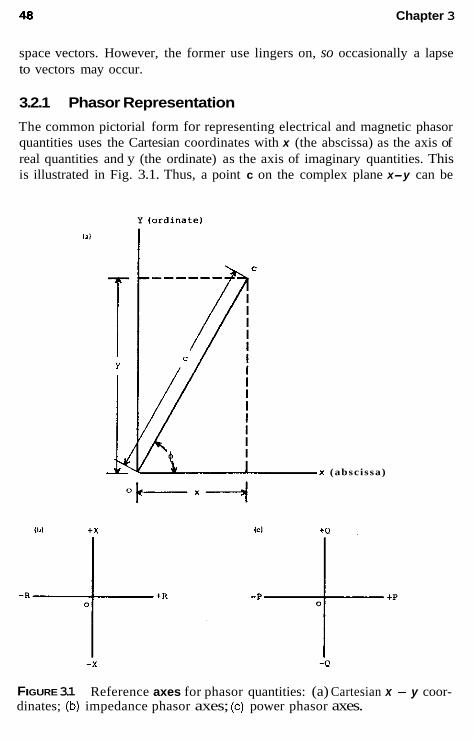
48 Chapter 3
space vectors. However, the former use lingers on, so occasionally a lapse to vectors may occur.
3.2.1 Phasor Representation
The common pictorial form for representing electrical and magnetic phasor quantities uses the Cartesian coordinates with x (the abscissa) as the axis of real quantities and y (the ordinate) as the axis of imaginary quantities. This is illustrated in Fig. 3.1. Thus, a point c on the complex plane x-y can be
Y lordinatel
(abscissa)
FIGURE 3.1 dinates; (b) impedance phasor axes; (c) power phasor axes.
Reference axes for phasor quantities: (a) Cartesian x ~ y coor-
Phasors and Polarity 49
represented as shown in this figure, and mathematically documented by the several alternative forms given in Eq. (3.1).
Phasor Rectangular Exponential Polar form form form Complex form form
c = x + j y = IcI(c0.s + + j sin +) = [cle’* = I c l m (3.1)
Sometimes useful is the conjugate form:
c* = x - jy = ~cl(cos 4 - j sin 4) = Icle” = l c l L 3 (3.2)
where
c = the phasor c* = its conjugate x = the real value (alternate: Re c or c’) y =the imaginary value (alternate: Im c or c”)
IcI =the modulus (magnitude or absolute value) 4 = the phase angle (argument or amplitude) (alternate: arg c)
The modulus (magnitude or absolute value) of the phasor is
ICI = (3.3)
From Eq. (3.1) and (3.3),
(3.4) 1 2
x = - (c + c*)
(3.5) 1
y = - (c - c*) 2j
3.2.2 Phasor Diagrams for Sinusoidal Quantities
In applying the preceding notation to sinusoidal (ac) voltages, currents, and fluxes, the axes are assumed fixed, with the phasor quantities rotating at constant angular velocity. The international standard is that phasors always rotate in the counterclockwise direction. However, as a convenience, on the diagrams the phasor is always shown as “fixed” for the given condition. The magnitude of the phasor c can be either the maximum peak value or the rms value of the corresponding sinusoidal quantity. In normal practice, it represents the rms maximum value of the positive half-cycle of the si- nusoid unless otherwise specifically stated.

50 Chapter 3
Thus, a phasor diagram shows the respective voltages, currents, fluxes, and so on, existing in the electric circuit. It should document only the mag- nitude and relative phase-angle relations between these various quantities. Therefore, all phasor diagrams require a scale or complete indications of the physical magnitudes of the quantities shown. The phase-angle reference usually is between the quantities shown, so that the zero (or reference angle) may vary with convenience. As an example, in fault calculations using re- actance X only, it is convenient to use the voltage Vreference at +90”. Then I = jV/jX and the j value cancels, so the fault current does not involve the j factor. On the other hand, in load calculations it is preferable to use the voltage Vat 0” or along the x axis so that the angle of the current I represents its actual lag or lead value.
Other reference axes that are in common use are shown in Fig. 3.lb and c. For plotting impedance, resistance, and reactance, the R-X axis of Fig. 3.lh is used. Inductive reactance is +X and capacitive reactance is -X.
For plotting power phasors, Fig. 3.lc is used. P is the real power (W, kW, MW) and Q is the reactive power (var, kvar, Mvar). These impedance and power diagrams are discussed in later chapters. Although represented as phasors, the impedance and power “phasors” do not rotate at system frequency.
3.2.3 Combining Phasors
Multiplication
The various laws for combining phasors are present for general reference:
The magnitudes are multiplied and the angles added:
VI = lVllIl/!3!K3 (3.6)
VI* = l V I / I l L 4 K 2 &
II* = 111‘
Division
The magnitudes are divided and the angles subtracted:
Powers
(3.7)
(3.8)
(3.9)
(3.10)
(3.11)

Phasors and Polarity 51
3.2.4 Phasor Diagrams Require a Circuit Diagram
The phasor diagram, defined earlier, has an indeterminate or vague meaning unless it is accompanied by a circuit diagram. The circuit diagram identifies the specific circuit involved, with the location and assumed direction for the currents, and the location and assumed polarity for the voltages to be doc- umented in the phasor diagram. The assumed directions and polarities are not critical, because the phasor diagram will confirm if the assumptions are correct, and provide the correct magnitudes and phase relations. These two complementary diagrams (circuit and phasor) are preferably kept separate to avoid confusion and errors in interpretation. This is discussed further in Section 3.3.
3.2.5 Nomenclature for Current and Voltage Unfortunately, there is no standard nomenclature for current and voltage, so confusion can exist among various authors and publications. The nomencla- ture used throughout this book has proved to be flexible and practical over many years of use, and it is compatible with power system equipment polarities.
Current and Flux
In the circuit diagrams, current or flux is shown by either (1) a letter des- ignation, such as I or 0, with an arrow indicator for the assumed direction of flow; or (2) a letter designation with double subscripts, the order of the subscripts indicating the assumed direction. The direction is that assumed to be the flow during the positive half-cycle of the sine wave. This convention is illustrated in Fig. 3.2a. Thus, in the positive half-cycle, the current in the circuit is assumed to be flowing from left to right, as indicated by the di- rection of the arrow used with I,, or denoted by subscripts, as with I,, Ih, and Icd. The single subscript such as Is, is a convenience to designate currents in various parts of a circuit and has no directional indication, so an arrow for the direction must be associated with these. Arrows are not required with lab, I,,, or I,, but are often used for added clarity and convenience.
It is very important to appreciate that in these circuit designations, the arrows do not indicate phasors. They are only assumed directional and lo- cation indicators.
Voltage Voltages can be either drops or rises. Much confusion can result by not clearly indicating which is intended or by mixing the two practices in circuit diagrams. This can be avoided by standardizing on one, and only one prac- tice. As voltage drops are far more common throughout the power system,

52 Chapter 3
l a1 L ' 8
Ibl
Open Type 0
Iab=Ibc=Icd=Is
C l o s e d Type
FIGURE^.^ Phasor diagram for the basic circuit elements: (a) circuit diagram showing location and assumed directions of current and of voltage drops; I and V are locational and directional indicators, not phasors; (b) phasor dia- grams showing current and voltage magnitudes and phase relations.
all voltages are shown and are always considered to be drops from a higher voltage to a lower voltage during the positive half cycle. This convention is independent of whether V, E, or U in many countries is used for the voltage. In this book, V is used and as indicated is afways a voltage drop.
The consistent adoption of only drops throughout does not need to cause difficulties. A generator or source voltage becomes a minus drop be- cause current flows from a lower voltage to a higher voltage. This practice does not conflict with the polarity of equipment, such as transformers, and it is consistent with fault calculations using symmetrical components.

Phasors and Polarity 53
Voltages (always drops) are indicated by either (1) a letter designation with double subscripts, or (2) a small plus (+) indicator shown at the point assumed to be at a relatively high potential. Thus, during the positive half- cycle of the sine wave, the voltage drop is indicated by the order of the two subscripts when used, or from the “+” indicator to the opposite end of the potential difference. This is illustrated in Fig. 3.2a, where both methods are shown. It is preferable to show arrows at both ends of the voltage-drop designations, to avoid possible confusion. Again, it is most important to recognize that both of these designations, especially if arrows are used, in the circuit diagrams are only location and direction indicators, not phasors.
It may be helpful to consider current as a “through” quantity and voltage as an “across” quantity. In this sense, in the representative Fig. 3.2a, the same current flows through all the elements in series, so that lab = Ik = I , = I.- By contrast, voltage V., applies only across nodes a and b, voltage V, across nodes b and c , and V, across nodes c and d.
3.2.6 The Phasor Diagram
With the proper identification and assumed directions established in the cir- cuit diagram, the corresponding phasor diagram can be drawn from calcu- lated or test data. For the circuit diagram of Fig. 3.2a, two types of phasor diagrams are shown in Fig. 3.2b. The top diagram is referred to as an open- type diagram, where all the phasors originate from a common origin. The bottom diagram is referred to as a closed-type, where the voltage phasors are summed together from left to right for the same series circuit. Both types are useful, but the open type is preferred to avoid the confusion that may occur with the closed type. This is amplified in Section 3.3.
3.3 CIRCUIT AND PHASOR DIAGRAMS FOR A BALANCED THREE-PHASE POWER SYSTEM
A typical section of a three-phase power system is shown in Fig. 3.3a. Optional grounding impedances (Z<J and (Z,,“) are omitted with solid grounding. This topic is covered in Chapter 7. (RJ and (RSJ represent the ground-mat resistance in the station or substation. Ground g or G represents the potential of the true earth, remote ground plane, and so on. The system neutrals n‘, n or N , and n” are not necessarily the same, unless a fourth wire is used, as in a four-wire three-phase system. Upper- or lowercase N and n are used interchangeably as convenient for the neutral designation.
The various line currents are assumed to flow through this series sec- tion, as shown, and the voltages are indicated for a specific point on the line section. These follow the nomenclature discussed previously. To simplify

vc* Ic-I Ic-Ib vc"=vcgD v an =v 89
ag
'ab 'b-'a 'a-Ic
vbc
v -" Vba v bn =v bg Ib-IC vac bn bg
'bc
OPEN TYPE CLOSED TYPE (b)
FIGURE 3.3 Phasor diagram for a typical three-phase circuit operating with balanced or symmetrical quantities: (a) circuit diagram showing location and assumed directions of current and voltage drops. I and V are locational and directional indicators, not phasors. (b) Phasor diagrams showing current and voltage magnitudes and phase relations.
54

Phasors and Polarity 55
the discussion at this point, symmetrical or balanced operation of the tbree- phase power system is assumed. Therefore, no current can flow in the neu- trals of the two transformer hanks, so that with this simplification there is no difference of voltage between n', n or N, n", and the ground plane g or G. As a result, V., = VnR; V,. = V,; and V, = V,. Again, this is true only for a balanced or symmetrical system. With this the respective currents and voltages are equal in magnitude and 120" apart in phase, as shown in the phasor diagram (see Fig. 3.3b), in both the open and closed types. The phasors for various unbalanced and fault conditions are discussed in Chap- ter 4.
The open-type phasor diagram permits easy documentation of all pos- sible currents and voltages, some of which are not convenient in the closed- type phasor diagram. The delta voltage V,,, representing the voltage (drop) from phase a to phase b, is the same as V.,, - V,. Similarly, V,, = V , , - V, and V,, = V,, - Vom.
As indicated, the closed-type phasor diagram can lead to difficulties. As seen in Fig. 3.3b, its shape lends itself mentally to an assumption that the three vertices of the triangle represent the a, b, and c phases of the power system, and that the origin 0 represents n = g. Questions arise with this closed-type phasor diagram about why V,, = V,, has its phasor arrow as shown, because the voltage drop is from phase a to neutral; similarly for the other two phases. Also why V,,, V,, and V,, are pointing as shown, for they are drops from phase a to phase b, phase b to phase c , and phase c to a , respectively. It would appear that they should be pointing in the opposite direction.
The phasors shown on this closed phasor diagram (see Fig. 3.3b) are absolutely correct and must not be changed. The difficulty is in the com- bining of a circuit diagram with the phasor diagram by the mental associ- ation of a , 6 , and c with the closed triangle. The open type avoids this difficulty. This also emphasizes the desirability of having two separate di- agrams: a circuit diagram and a phasor diagram. Each serves particular, but quite different, functions.
3.4 PHASOR AND PHASE ROTATION
Phasor and phase rotation are two entirely different terms, although they almost look alike. The ac phasors always rotate counterclockwise at the system frequency. The fixed diagrams, plotted such as in Fig. 3.3b, represent what would be seen if a stroboscopic light of system frequency were im- posed on the system phasors. The phasors would appear fixed in space as plotted.

56 Chapter 3
In contrast, phase rotation or phase sequence refers to the order in which the phasors occur as they rotate counterclockwise. The standard se- quence today is: a , b, c; A , B, C, 1, 2, 3; or in some areas r, s, t. In Fig. 3.3h the sequence is a , b, c. The IEEE dictionary (IEEE 100) defines only phase sequence; hence, this is preferred. However, phase rotation has been used over many years and is still used in practice.
Not all power systems operate with phase sequence a , b, c, or its equivalent. There are several large electric utilities in the United States that operate with a, c, b phase sequence. Occasionally, this sequence is used throughout the system; for others, one voltage level may he a, b, c, and another voltage level, a , c, b. The specific phase sequence is only a name designation that was established arbitrarily early in the history of a company, and it is difficult to change after many years of operation.
A knowledge of the existing phase sequence is very important in three- phase connections of relays and other equipment; therefore, it should be clearly indicated on the drawings and information documents. This is es- pecially true if it is not a, b, c. The connections from a , b, c, to a, c, b, or vice versa, can generally be made by completely interchanging phases b and c for both the equipment and the connections.
3.5 POLARITY
Polarity is important in transformers and in protection equipment. A clear understanding of polarity is useful and essential for the chapters that follow.
3.5.1 Transformer Polarity
The polarity indications for transformers are well established by standards that apply to all types of transformers. There are two varieties of polarity: subtractive and additive. Both follow the same rules. Power and instrument transformers are subtractive, whereas some distribution transformers are ad- ditive. The polarity marking can he a dot, a square, or an X, or it can be indicated by the standardized transformer terminal markings, the practices having varied over the years. It is convenient to designate polarity by an X in this book.
The two fundamental rules of transformer polarity are illustrated in Fig. 3.4 and apply to both varieties. These are
1. Current flowing in at the polarity mark of one winding flows out of the polarity mark of the other winding. Both currents are suh- stantially in-phase.

Phasors and Polarity
(81
P R I .
57
Ibl Ip d +
P R I . 71 [Ti.. + -1s
FIGURE 3.4 additive polarity.
Polarity definitions for transformers: (a) subtractive polarity: (b)
2. The voltage drop from polarity to nonpolarity across one winding is essentially in phase with the voltage drop from polanty to non- polarity across the other winding(s).
The currents through, and the voltages across, the transformers are substantially in phase, because the magnetizing current and the impedance drop through the transformers is very small and can be considered negligible. This is normal and practical for these definitions.
The current transformer polarity markings are shown in Fig. 3.5. Note that the direction of the secondary current is the same independent of whether the polarity marks are together on one side or on the other. - IP
SEC . SEC
FIGURE 3.5 Polarity markings for current transformers.
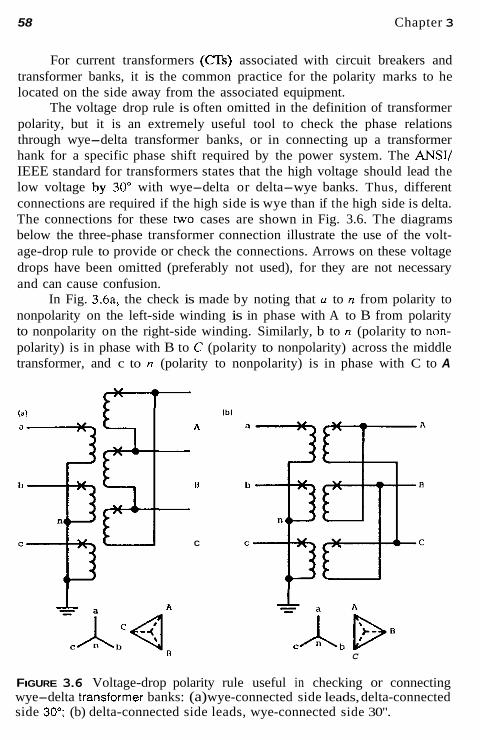
58 Chapter 3
For current transformers ( a s ) associated with circuit breakers and transformer banks, it is the common practice for the polarity marks to he located on the side away from the associated equipment.
The voltage drop rule is often omitted in the definition of transformer polarity, but it is an extremely useful tool to check the phase relations through wye-delta transformer banks, or in connecting up a transformer hank for a specific phase shift required by the power system. The ANSI/ IEEE standard for transformers states that the high voltage should lead the low voltage by 30" with wye-delta or delta-wye banks. Thus, different connections are required if the high side is wye than if the high side is delta. The connections for these two cases are shown in Fig. 3.6. The diagrams below the three-phase transformer connection illustrate the use of the volt- age-drop rule to provide or check the connections. Arrows on these voltage drops have been omitted (preferably not used), for they are not necessary and can cause confusion.
In Fig. 3.6a, the check is made by noting that u to n from polarity to nonpolarity on the left-side winding is in phase with A to B from polarity to nonpolarity on the right-side winding. Similarly, b to n (polarity to non- polarity) is in phase with B to C (polarity to nonpolarity) across the middle transformer, and c to n (polarity to nonpolarity) is in phase with C to A
181 lbi A
U !it C
C
FIGURE 3.6 Voltage-drop polarity rule useful in checking or connecting wye-delta transformer banks: (a) wye-connected side leads, delta-connected side 30'; (b) delta-connected side leads, wye-connected side 30".

Phasors and Polarity 59
(polarity to nonpolarity) across the lower transformer. From this, by com- paring the line-to-neutral voltages on the two sides, it is observed that phase- a-to-n voltage leads phase-A-to-neutral voltage. Accordingly, the wye side would be the high-voltage side if this is an ANSI/IEEE standard transformer.
This same technique of applying voltage drops to Fig. 3.6b shows that for this three-phase bank connection the voltage drop polarity to nonpolarity or phase a to n is in phase with the voltage drop,polarity to nonpolarity or phase A to phase C. Similarly, voltage drop phase b to n is in phase with voltage drop phase B to A, and voltage drop phase c to n is in phase with voltage drop phase C to phase B. By comparing similar voltages on the two sides of the transformer, phase-A-to-neutral voltage drop leads the phase-a- to-n voltage drop by 30", so the delta winding would be the high-voltage side if this is an ANSI/IEEE standard transformer bank. This technique is very useful to make the proper three-phase transformer connections from a desired or known voltage diagram or phase-shift requirement. It is a very powerful tool, simple and straightforward to use.
Because the ANSI/IEEE standards have been in existence for several years, most transformer banks in service today follow this standard, except where it is not possible because of preexisting system conditions. Many years ago, in the absence of a standard, a great many different connections were used. Some of the older references and textbooks reflect this.
3.5.2 Relay Polarity Relays involving interaction between two input quantities from the power system may have the polarity marking that is necessary for their correct operation. There are no standards in this area, so if the polarity of the relay connections is important, the relay manufacturer must both specify the po- larity markings and clearly document their meaning. Relays that sense the direction of current (or power) pow at a specific location and, thereby, in- dicate the direction of the fault, provide a good practical example of relay polarity. Directional units are usually not applied alone, but rather, in com- binations with other units, such as fault sensors or detectors. A common practice is to use the output of the directional-sensing unit to control the operation of the fault sensors, which often is an instantaneous or an inverse- time-overcurrent unit, or both units together. Thus, if the current flow is in the desired operating direction (trip direction) and its magnitude is greater than the fault sensor's minimum-operating current (pickup), the relay can operate. If the current is in the opposite direction (nontrip or nonoperate direction or zone), no operation can occur even though the magnitude of the current is higher than the pickup threshold current.
A directional-sensing unit requires a reference quantiry that is reason- ably constant against which the current in the protected circuit can be com-

60 Chapter 3
pared. For relays intended to provide operation for phase-type faults, one of the system voltages of Fig. 3.3b can be used as a reference. For all practical purposes, most system voltages do not change their phase positions signif- icantly during a fault. In contrast, line currents can shift around 180” (es- sentially reverse their direction or flow) for faults on one side of the circuit CTs relative to a fault on the other side of the CTs.
Typical polarity indications for three commonly used directional- sensing units are shown in Fig. 3.7. This uses the custom of showing several loops for voltage coils and a single loop for current coils, of placing the reference circuit or voltage circuit above the current circuit, and of placing the polarity markings diagonally, all as shown on the relay schematics in Fig. 3.7.
The reference quantity is commonly called the “polarizing” quantity, especially for ground-fault relaying, where either or both current and voltage polarizing is used. The polarity marks (Fig. 3.7) are small plus symbols (+) placed, as illustrated, above one end of each coil, diagonally as shown, or
Maximum Torque Line
Torque L i n e
- 1. o p e r a t e 4
A ) 3 0 0 Type ’One
~ N o n - O p e r a t e U r t l t
a - - zone
Maximum Torque L i n e
8 ) 60° Type unit
Loperate
Zero Torque N o n - O ~ e r a t e L i n e - . zone
Maxirnu Toroue
C) 00 Type u n i t
v + 6-I
Vol t age Polarized D i r e c t i o n a l Relay
I
Current Polarized D i r e c t i o n a l Relay
FIGURE 3.7 Typical directional relay characteristics.

Phasors and Polarity 61
on the opposite diagonal. As shown in Fig. 3.5, relay operation is not af- fected whether the polarity marks are on one diagonal or the other.
The meaning of the polarity for a specific relay must he stated clearly in words or by a diagram, such as the one shown in Fig. 3.7. These show the basic design characteristics of an individual relay, independently of any connection or association with the power system. The terms maximum torque line and zero torque line come from the electromechanical designs long used and still common in the industry. With solid-state designs, these would he the operating lines or thresholds, but the well-established terminology no doubt will continue for many years for all types of designs.
The interpretation of relay polarity is illustrated in Fig. 3.7 for three typical electromechanical units. Solid-state units can have adjustments for (1) the maximum torque angle and (2) the angle limits of the operate zone, but the application and operation is the same for both types. In Fig. 3.7A the maximum operating torque or energy occurs when the current flow from polarity to nonpolarity (I,) leads by 30" the voltage drop from polarity to nonpolarity (V,.). The minimum pickup of the directional unit is specified at this maximum torque or operating condition. As seen, the unit will operate for currents from almost 60" lagging the reference voltage V,, to almost 120" leading. The operate (trip, contact close) zone or area is represented by the half plane, bordered on one side by the zero-torque (nonoperating) line and extending in the direction that contains both the reference (polarizing) and operating quantities. Higher-current values will he required when Ip,, deviates from the maximum torque line. The solid-state relays can adjust this torque line far increased sensitivity by adjusting it to the fault line. The operating torque at any angle is a function of the cosine of the angle between the current (I,,,,) and the maximum-torque line, as well as the magnitudes of the operating quantities.
For ground fault protection the 60" unit of Fig. 3.7B is used with a 3 V,, reference (see Fig. 3.9) and the zero (watt) unit of Fig. 3.7C with a 3 I,! current reference (see Fig. 3.10).
The Fig. 3.7C unit is also used for power or var applications. A typical application is reverse power protection for a generator.
A similar type of Fig. 3.7A electromechanical directional unit has its maximum-torque angle at 45" leading, instead of 30" leading. Both units are in wide use for phase-fault protection. Solid-state units with an adjustable angle feature can provide a range of angles.
3.6 APPLICATION OF POLARITY FOR PHASE-FAULT DIRECTIONAL SENSING
Several phase voltages (see Fig. 3.3b) exist within the power system and are available for consideration as the reference quantity for directional re-

w
TAELE 3.1 Connection Chart for Phase-Fault Directional Sensino
Phase Maximum torque Phase A Phase B
Connection Unit type / V / V / V occurs when
1 30" Fig. 3.7C I* Vac I , v,. 4 VC.0 I lags 30" 2 60" delta Fig. 3.7C /A v,, L - I C v, L-L v, I lags 60' 3 6O0wye Fig. 3.7C I, -vc I , -v, I , - V b / lags 60' 4 90'-45" Fig. 3.7A but maximum I, V b , Ib V, I0 V., / lags 45'
5 90"-60" Fig. 3.7A I . V b , / b V, 1, V., / lags 60' torque at 45"

Phasors and Polarity 63
laying. Five different connections for phase-fault directional sensing have been used over the years. These are outlined in Table 3.1. For a number of years connections 4 and 5 have been used almost exclusively, so these will be discussed. The other three, in very limited applications, are outlined in Table 3.1 for reference only.
Connections 4 and 5 are fundamentally the same, and they are known as the "90" connection." The only difference between them is the angle that the system current lags the system voltage for maximum-operating torque or energy. Either 60" or 45" is the typical angle of the fault current for maximum energy or torque. The difference is of no significance because the cos (60" - 45") = 0.97, and the typical pickup of these types of direc- tional units is about 2-4 VA or less. With the normal 120 V available to the relay, this represents a current sensitivity of about 0.02-0.04 A. As a result, the normal power load in the operating zone will operate the phase directional units, but the relay will not operate unless a fault has occurred to increase the current above the fault-sensing unit's pickup. Again the solid- state units can have an adjustable maximum-torque line.
3.6.1 The 90"-60" Connection for Phase-Fault Protection
The 90" connection (see 4 and 5 of Table 3.1) applies a power system voltage that lags the power system unrrypowerfuctor current by 90". These voltages and currents are obtained from the power system through voltage and current transformers. Typical three-phase connections are shown in Fig. 3.8. Three separate units are used, one for each of the three phases of the power system. Only the directional sensing units are illustrated, with the fault sensors or detectors omitted for this discussion. They are shown packaged by phase, hut other packaging combinations are possible.
The phase A directional unit receives I., and from the system phasors of Fig. 3.3b, the 90" lagging voltage is V,. The phase B directional unit receives I,, where the 90" lagging voltage is V,, and the phase C directional unit receives I , where the 90" lagging voltage is V",,. These are also shown in Table 3.1 for connections 4 and 5 and in Fig. 3.8.
In Fig. 3.8a the currents are connected so that when I., Ib, and 1, are flowing in the direction indicated by the "trip direction" arrow, the second- ary currents flow through the directional units from polarity to nonpolarity. The polarity of the ' 3 s does not have to go to the polarity of the relay, although often that is convenient, as in this example.
With the trip direction of the currents established in the directional unit current coils, the voltages V,, on unit A, V,, on unit B, and V., on unit C must be connected from polarity to nonpolarity on the directional unit volt-

64
1-1 ,
CTS
Chapter 3
PHISB SEQUENCE a.b.c a BUS ~ SISTEH kv
V." I I.11OOSP.F.)
naximun zero Torque
"bc r--roperate zone
,:boo
\
FIGURE 3.8 (a) Typical three-line connections for phase-fault directional sensing using the 30" unit of Fig. 3.7A. (b) Connections also show the ground fault directional sensing using the 60' unit of Fig. 3.76. More detail and phasor diagram are shown in Fig. 3.9

Phasors and Polarity 65
age coils, as shown. The right-hand phasor diagram of Fig. 3.8b applies the directional unit characteristic of Fig. 3.7A to the power system phasors. The maximum-torque line leads the voltage by 30", so with V,,, polarity to non- polarity on the relay voltage winding, the maximum-torque line is drawn 30" leading, as illustrated in the lower right-hand phasor diagram. This is 60" lagging the unity power factor position of the current phasor I,. There- fore, whenever the phase a current in the power system lags by 60", the directional unit will operate at maximum torque with the lowest pickup value and the highest sensitivity. Because most system faults provide relatively large currents, the range of possible operation is for power system currents from almost 30" leading to 150" lagging in the "trip direction." This is the operating zone shown in Fig. 3.8. Similar relations exist for the other hvo- phase units using Ih and I , phase currents.
Thus, the foregoing discussion describes the Y0"-60" connection, where a YO" lagging voltage is used, and maximum operation occurs when the phase current lags in the system by 60". The Y0"-45" connection is identical, except that the relay design provides maximum torque, leading the reference voltage by 45", rather than by 30", used for illustration.
Solid-state relays provide the possibility of restricting the operating zone. For most power system faults, the current will lag the fault voltage from close to say 5" to 15" (large arc resistance at low voltages) to 80"-85" at the high voltages; thus, restricting the operate zone by adjusting the zero torque lines is practicable.
Wye-wye-connected voltage transformers (VTs) are shown in the typ- ical connections of Fig. 3.8a. Open-delta connections using only two VTs to provide three-phase voltage can be used as an alternative. This is appli- cable only for phase-fault protection, not for ground protection.
3.7 DIRECTIONAL SENSING FOR GROUND FAULTS: VOLTAGE POLARIZATION
The connections of a directional-sensing unit for ground-fault protection using a voltage reference (voltage polarization) are shown in Fig. 3.8a and in greater detail in Fig. 3.9. Although the phase relays of Section 3.6 were connected and analyzed using balanced three-phase voltages and currents, it is necessary to assume a fault involving the ground for a ground relay. Thus, a phase-a-to-ground fault is assumed in the trip direction, as shown in Fig. 3.9. The characteristics of this type of fault generally are a collapse of the faulted-phase voltage (VJ with an increase and lag of the faulted-phase current (Io), such as typically illustrated in the left phasor diagram. In many cases the unfaulted (b and c) phase currents are small and negligible prac- tically, so that their phase-to-ground voltages are essentially uncollapsed.

66 Chapter 3
ZERO TORQUE LINE
FIGURE 3.9 Typical three-line connections for ground-fault directional sens- ing with voltage polarization using the 60" unit of Fig. 3.78.

Phasors and Polarity 67
The assumption here is that Ih = I , = O, so that I. = 31e This, together with V, or 3V0, is a zero-sequence quantity, reviewed in Chapter 4.
In Fig. 3.9, a voltage polarizing (voltage reference) is shown that uses the 3V, zero-sequence voltage derived from a "broken-delta" connection of the VIS (in this example the auxiliary VTs). This voltage is the sum of the three-phase-to-ground voltages, as shown in the connections and in middle phasor diagram. For halanced conditions this 3V0 voltage is zero.
For ground-fault protection a directional 60" unit (see Fig. 3.7B) is used. The connections show that with I, fault current flowing in the tripping direction and to the fault, the secondary current flows in the ground relay from its polarity-to-nonpolarity direction. To provide proper operation it be- comes necessary to apply -3V, to the ground relay voltage coil from po- larity to nonpolarity, as shown in the connections and the right phasor dia- gram, where the operation is as indicated. With -3V0 connected to the ground relay from polarity to nonpolarity, the relay characteristic of Fig. 3.7B indicate that maximum torque will occur when the current polarity-to- nonpolarity lags in the power system hy 60". Thus, the maximum-torque line is drawn as shown in the lower-right phasor diagram of Fig. 3.9. As long as the magnitudes of -3V0 and 310 are above the pickup of the direc- tional unit, it will operate for currents from nearly 30" leading to 150" lagging.
Ground faults on power systems, as do phase-faults, lag the fault volt- age up to about 80"-85"; therefore, solid-state relays in which the zero torque lines can be changed are useful to limit the operate zone from thai shown in Fig. 3.9.
An alternative check of these connections may be made by assuming that the VTs are a "ground source" with current flowing from the ground through the primary of the VT to the fault. If one traces this ihrough the VT windings, this assumed current together with the fault current from the system, will flow from polarity to nonpolarity in both of the ground relay windings.
3.8 DIRECTIONAL SENSING FOR GROUND FAULTS: CURRENT POLARIZATION
The current that flows in ihe grounded neutral of a wye-delta power or distribution transformer bank can be used as a reference or polarizing quan- tity for ground-fault protection. Typical connections are shown in Fig. 3.10. Again no current can flow to the ground relay either from the fault or from the transformer bank neutral if the power system is halanced. Thus a phase- a-to-ground fault is shown on phase a in the trip direction. For simplifica- tion, I, and I , phase currents are assumed to be zero. For all practical pur-

68 Chapter 3
Crovnd Favlt
FIGURE 3.10 Typical three-line connections for ground-fault directional sens- ing with current polarization using the 0" unit of Fig. 3.7C.
poses the current flowing into the fault will be essentially in phase with the current flowing up the transformer bank neutral, so the 0"-type ground relay with characteristics, as shown in Fig. 3.7C, is applicable and is the one used in Fig. 3.10 connections.
To illustrate and to emphasize that the polarity marks on the current transformers do not have to be connected to the polarity-marked terminal of the relay, the fault I. current from the (JTs on the line have been connected arbitrarily so that I , flows from nonpolarity to polarity on the relay coil. Therefore, the polarizing secondary current I , must be connected from non- polarity to polarity when the primary fault I , flows up the neutral of the transformer.
With the currents I, and I, in phase, maximum operating torque will occur as in Fig. 3.7C. Operation is still possible, as one current leads or lags by almost 90" from the other, as long as the magnitudes are higher than the required pickup values for the directional unit. It should be obvious that the connections of Fig. 3.10 are also correct (also for Fig. 3.9) if the operating

Phasors and Polarity 69
quantity I. (31,,) and the polarizing quantity are both reversed at the direc- tional relay.
3.9 OTHER DIRECTIONAL-SENSING CONNECTIONS
Various other directional-sensing connections can be derived to measure dif- ferent power factor areas by connecting the different (or other) units of Fig. 3.7 to various combinations of currents or current and voltage. One type of connection is used to operate on power, either watts or vars, flowing in the power system. These relays (designated device 32) are available with various operating power levels.
For watt measurement, the 0" unit of Fig. 3.7C can be used with star (or delta) current or voltage. For example, this unit, used with I. phase current and V.. voltage, will give maximum torque when these two quantities are in phase. Also, ]*-Ih with V., could be used. For var measurement, I, with V,, provides maximum torque when I, lags 90" and zero torque when I. is at unity power factor and flowing in either direction.
A watt-power relay (32) can also be obtained by using the 30" unit of Fig. 3.7A with I , and Vet. This places the maximum-torque line in phase with the unit power factor position of I.. Similarly, a var-type relay can be obtained using this 30" unit with I , and Vb,,. This provides maximum torque when I , lags by 90".
3.10 SUMMARY
The fundamental methodology of phasors and polarity reviewed in this chap- ter will be employed throughout the rest of the book. As stressed previously, these concepts are essential as useful aids in the selection, connection, op- eration, performance, and testing of the protection for all power systems.

-
Symmetrical Components: A Review
4.1 INTRODUCTION AND BACKGROUND
The method of symmetrical components provides a practical technology for understanding and analyzing power system operation during unbalanced conditions, such as those caused by faults between phases and ground, open phases, unbalanced impedances, and so on. Also, many protective relays operate from the symmetrical component quantities. Thus, a good under- standing of this subject is of great value and another very important tool in protection.
In a sense “symmetrical components” can be called the language of the relay engineer or technician. Its value is both in thinking or visualizing unbalances, as well as a means of detailed analysis of them from the system parameters. In this simile, it is like a language in that it requires experience and practice for each access and application. Faults and unbalances occur infrequently, and many do not require detailed analysis, so it becomes dif- ficult to “practice the language.” This has increased with the ready avail- ability of fault studies by computers. These provide rapid access to volu- minous data, often with little user understanding of the background or method that provides the data. Hence, this review of the method is intended
70
Symmetrical Components 71
to provide the fundamentals, basic circuits and calculations, and an overview directed at clear understanding and visualization.
The method of symmetrical components was discovered by Charles L. Fortescue, who was investigating mathematically the operation of induction motors under unbalanced conditions late in 1913. At the 34th Annual Con- vention of the AIEE-on June 28, 1918, in Atlantic City-he presented an 89-page paper entitled Method of Symmetrical Co-ordinates Applied to the Solution of Polyphase Networks. The six discussants, including Steinmetz, added 25 pages. Practical application for system fault analysis was devel- oped by C. F. Wagner and R. D. Evans in the later part of 1920s and early 1930s, with W. A. Lewis adding valuable simplifications in 1933. E. L. Harder provided tables of fault and unbalance connections in 1937. Edith Clarke was also developing notes and lecturing in this area at this time, but formal publication of her work did not occur until 1943. Additional material and many examples for further study are found in Blackburn (1993).
Only symmetrical components for three-phase systems will be re- viewed here. For these systems there are three distinct sets of components: positive, negative, and zero for both current and voltage. Throughout this discussion, the sequence quantities are always line-to-neutral or line-to- ground, as appropriate. This is an exception for voltage, whereas in the power system, line-to-line voltages are commonly indicated, but in sym- metrical components they are always line-to-neutral (or possibly line-to- ground).
4.2 POSITIVE-SEQUENCE SET
The positive-sequence set consists of the balanced three-phase currents and line-to-neutral voltages supplied by the system generators. Thus, they are always equal in magnitude, and are phase-displaced by 120". With the power system phase sequence of a, b, c, Fig. 4.1 shows a positive-sequence set of phase currents. A voltage set is similar except for line-to-neutral voltage of the three phases, again all equal in magnitude and displaced 120". These are phasors rotating counterclockwise at the system frequency.
To document the angle displacement, it is convenient to use a unit phasor with an angle displacement of 120". This is designated as a so that
a = 1/120" = -0.5 + j0.866
a' = 1& = -0.5 ~ j0.866
a' = 1/360" = I& = 1.0 + j o

72 Chapter 4
FIGURE 4.1 clockwise.
Positive-sequence current phasors. Phasor rotation is counter-
Therefore, the positive-sequence set can be designated as
I,, = I, v,, = v, I,, = a 2 ~ # , = aZI, = I,&
I,, = al., = ar, = 1,m
v,, = a ' ~ , = ~,/240" v,, = av, = v , m
(4.2)
It is most important to emphasize that the set of sequence currents or sequence voltages always exists as defined. la,, or Ib,2 or I,, can never exist alone or in pairs, always all three. Thus it is necessary to define only one of the phasors (any one), from which the other two will be as documented in Eq. (4.2).
4.3 NOMENCLATURE CONVENIENCE It will be noted that the designation subscript for phase a was dropped in the second expression for the currents and voltages in Eq. (4.2) (and also in the following equations). This is a common shorthand notation used for convenience. Whenever the phase subscript does not appear, it can be as- sumed that the reference is to phase a. If phase b or phase c quantities are intended, the phase subscript must be correctly designated; otherwise, it is assumed to be phase a. This shortcut will be used throughout the book and is common in practice.
4.4 NEGATIVE-SEQUENCE SET
The negative-sequence set is also balanced with three equal magnitude quan- tities at 120" apart, but with the phase rotation or sequence reversed as
Symmetrical Components 73
illustrated in Fig. 4.2. Thus, if positive sequence is a, b, c, negative will be a, c, b. Where positive sequence is a, c, b, as in some power systems, negative sequence is a, b, c.
The negative-sequence set can be designated as
L 2 = 1 2 V", = v* lh2 = aIa2 = al, = 1~/1200
= a2tO2 = a212 = 1~/2400 v,, = av, = ~,/120" v,, = a'v, = ~,/240"
(4.3)
Again, negative sequence always exists as a set of current or voltage as defined in the foregoing or in Fig. 4.2 Iu2, or I,,>, or Ic2, can never exist alone. When one current or voltage phasor is known, the other two of the set can be defined as above.
4.5 ZERO-SEQUENCE SET The members of this set of rotating phasors are always equal in magnitude and always in phase (Fig. 4.3).
I,, =I,, = I& = la
Again, lo or V,, if it exists, exists equally in all three phases, never
V." = v,, = v,, = v, (4.4)
alone in one phase.
4.6 GENERAL EQUATIONS Any unbalanced current or voltage can be determined from the sequence components from the following fundamental equations:
v, = v, + v, + V" V,, = a2v, + av, + v, V, = a v , + a2v, + V,
I" = I, i I2 i I" Ih = a21, + al, + I ,
1, = all + a'r, +
(4.5)
(4.6)
(4.7)
where I,, Ib, and I, or V,, V,, and V, are general unbalanced line-to-neutral phasors.
From these, equations defining the sequence quantities from a three- phase unbalanced set can be determined:
I - I 0 - 1 (1- + I b + I,, I, = +(Ia + a& + a*[,)
V" = f(V" + v, + V,)
v, = f(v. + av, + a'v,) (4.8)
(4.9) I2 = +(Ic + a'l, + al,) v - - I (v. + a2Vb + a t ) (4.10)

74 Chapter 4
FIGURE 4.2 clockwise.
Negative-sequence current phasors. Phasor rotation is counter-
These last three fundamental equations are the basis for determining if the sequence quantities exist in any given set of unbalanced three-phase currents or voltages. They are used for protective-relaying operation from the sequence quantities. For example, Fig. 4.4 shows the physical application of current transformers ( a s ) and voltage transformers (VTs) to measure zero sequence as required by Eq. (4.8), and used in ground-fault relaying.
Networks operating from (JTs or VTs are used to provide an output proportional to I2 or V, and are based on physical solutions of (Eq. 4.10). This can be accomplished with resistors, transformers, or reactors; or by digital solutions of Eqs. (4.8) through (4.10).
4.7 SEQUENCE INDEPENDENCE
The key that makes dividing unbalanced three-phase quantities into the se- quence components practical is the independence of the components in a
FIGURE 4.3 Zero-sequence current phasors. Phasor rotation is counter- clockwise.

Symmetrical Components 75
CT5
b
c
FIGURE 4.4 Zero-sequence current and voltage networks used for ground- fault protection. See Figs. 3.9 and 3.10 for typical fault operation.
balanced system network. For all practical purposes, electric power systems are balanced or symmetrical from the generators to the point of single-phase loading, except in an area of a fault or unbalance, such as an open conductor. In this essentially balanced area, the following conditions exist:
1. Positive-sequence currents flowing in the symmetrical or balanced network produce only positive-sequence voltage drops; no nega- tive- or zero-sequence drops. Negative-sequence currents flowing in the balanced network pro- duce only negative-sequence voltage drops; no positive- or zero- sequence voltage drops. Zero-sequence currents flowing in the balanced network produce only zero-sequence voltage drops; no positive- or negative- sequence voltage drops.
2.
3.
This is not true for any unbalanced or nonsymmetrical point or area, such as an unsymmetrical fault, open phase, and so on. In these
4. Positive-sequence current flowing in an unbalanced system pro- duces positive- and negative- and possibly zero-sequence voltage drops. Negative-sequence currents flowing in an unbalanced system pro- duces positive-, negative-, and possibly zero-sequence voltage drops.
5.

76 Chapter 4
6. Zero-sequence current flowing in an unbalanced system produces all three: positive-, negative-, and zero-sequence voltage drops.
This important fundamental permits setting up three independent net- works, one for each of the three sequences, which can be interconnected only at the point or area of unbalance.
Before continuing with the sequence networks, a review of the sources of fault current is useful.
4.8 POSITIVE-SEQUENCE SOURCES
A single-line diagram of the power system or area under study is the starting point for setting up the sequence networks. A typical diagram for a section of a power system is shown in Fig. 4.5. In these diagrams, circles are used to designate the positive-sequence sources, which are the rotating machines in the system; generators, synchronous motors, synchronous condensers, and possibly induction motors. The symmetrical current supplied by these to power system faults decreases exponentially with time from a relative high initial value to a low steady-state value. During this transient period three reactance values are possible for use in the positive-sequence network and for the calculation of fault currents. These are the direct-axis subtransient reactance Xi, the direct-axis transient reactance X:, and the unsaturated di- rect-axis synchronous reactance X,.
The values of these reactances vary with the designs of the machines, and specific values are supplied by the manufacturer. In their absence typical values are shown in Blackburn (1993, p. 279) and in many other references. Very generally, typical values at the machines rated MVA (kVA), and rated kV are; similarily X," = 0.1 to 0.3 pu, with time constants of about 0.35 s; X i = 1.2-2.0 Xz , with time constants in the order of 0.6-1.5 s; X, for faults is the unsaturated value that can range from 6 to 14 times X:.
- 'LH
FIGURE 4.5 Single-line diagram of a section of a power system

Symmetrical Components 77
For system-protection fault studies the almost universal practice is to use the subtransient (X:) for the rotating machines in the positive-sequence networks. This provides a maximum value of fault current useful for high- speed relaying. Although slower-speed protection may operate after the sub- transient reactance has decayed into the transient reactance period, the general practice is to use X: except possibly for special cases where Xi would be used. There are special programs to account for the decremental decay in fault current with time in setting the slower-speed protective relays, hut these tend to he difficult and tedious, and may not provide any substan- tial advantages. A guide to aid in the understanding of the need for special considerations is outlined in Fig. 4.6. The criteria are very general and approximate.
Cases A and B (see Fig. 4.6) are the most common situations, so that the use of X: has a negligible effect on the protection. Here the higher system Zr tends to negate the source decrement effects.
Case C (see Fig. 4.6) can affect the overall time operation of a slower- speed protection, but generally the decrease in fault current level with time will not cause coordination problems unless the time-current characteristics of various devices used are significantly different. When Z , predominates, the fault levels tend to be high and well above the maximum-load current. The practice of setting the protection as sensitive as possible, but not op- erating on maximum load (phase devices) should provide good protection sensitivity in the transient reactance period. If protection-operating times are very long, so that the current decays into the synchronous reactance period, special phase relays are required, as discussed in Chapter 8.
Usually, induction motors are not considered sources of fault current for protection purposes (see Fig. 4.6, case I)). However, it must be empha- sized that these motors must be considered in circuit breakers’ applications under the ANSIflEEE standards. Without a field source, the voltage devel- oped by induction motors decays rapidly, within a few cycles, so they gen- erally have a negligible effect on the protection.
The dc offset that can result from sudden changes in current in ac networks is neglected in symmetrical components. It is an important con- sideration in all protection.
An equivalent source, such as that shown in Fig. 4.5, represents the equivalent of all of the system not shown up to the point of connection to the part of the system under study. This includes one or many rotating machines, together with any network of transformers, lines, and so on, that may be interconnected. In general, a network system can he reduced to two equivalent sources at each end of an area to he studied, with an equivalent interconnecting tie between these two equivalent sources. When this equiv- alent tie is very large or infinite, indicating that little or no power is ex-

78 Chapter 4
Rotating Machine system
ZM zs Fault h
Utility Systems
Station Areas,
Industrial Plants With Utjlity Tie and NO oi Small L o c a l Generatio".
OulSLde ceneratinq
ZM<%
Near Generating
Industrial Plants With Utility Tie and Significant Local Generation.
zMapprox. = stations.
At Generating
Industrial Plante With AI1 Local Generation, No Utility TIe.
stations,
FIGURE 4.6 Guide illustrating the effects of rotating rnachine decrements on the symmetrical fault current.

Symmetrical Components 79
changed between the two source systems, it is convenient to express the equivalent source system up to a specified bus or point in short-circuit MVA (or kVA). Appendix 4.1 outlines this and the conversion to impedance or reactance values. In Fig. 4.5, the network to the right has reduced to a single equivalent impedance to represent it up to the M terminal of the three- winding transformer bank.
4.9 SEQUENCE NETWORKS The sequence networks represent one of the three-phase-to-neutral or ground circuits of the balanced three-phase power system, and document how their sequence currents will flow if they can exist. These networks are best ex- plained by an example: let us now consider the section of a power system of Fig. 4.5.
Reactance values have been shown for only the generator and the transformers. Theoretically, impedance values should be used, hut the resis- tances of these units are very small and negligible for fault studies. However, if loads.are included, impedance values should be used unless their values are very small relative to the reactances.
It is very important that all values he specified with a base [voltage if ohms are used, or MVA (kVA) and kV if per unit or percent impedances are used]. Before applying these to the sequence networks, all values must be changed to one common base. Usually, per unit (percent) values are used, and a common base in practice is 100 MVA at the particular system kV.
4.9.1 Positive-Sequence Network
This is the usual line-to-neutral system diagram for one of the three sym- metrical phases modified for fault conditions. The positive-sequence network for the system of Fig. 4.5 is shown in Fig. 4.7. V, and V, are the system line-to-neutral voltages. V, is the voltage behind the generator subtransient direct-axis reactance Xi, and V, is the voltage behind the system equivalent impedance ZLs.
X,, is the transformer leakage impedance for the hank bus G, and X,,, is the leakage impedance for the bank at H between the H and M windings. More detail on these is given in Appendix 4.2. The delta-winding L of this three-winding hank is not involved in the positive-sequence network unless a generator or synchronous motor is connected to this delta or unless a fault is to he considered in the L delta system. The connection would be as in Fig. A4.2-3.
For the line between buses G and H, Z,, , is the line-to-neutral impe- dance of this three-phase circuit. For open-wire transmission lines, an ap-
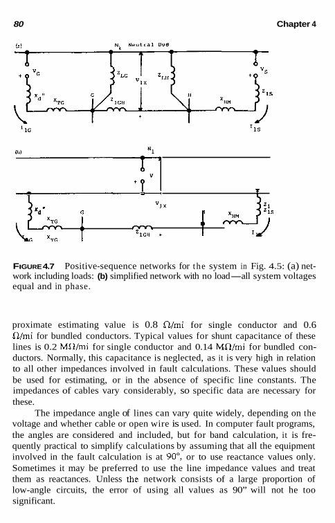
80 Chapter 4
I., N. Neutral BUS
- - - “ 1 X
‘d ” r, H 215 J- IIG XTG t =Id&* + t J! 11s rm
FIGURE 4.7 Positive-sequence networks for the system in Fig. 4.5: (a) net- work including loads: (b) simplified network with no load-all system voltages equal and in phase.
proximate estimating value is 0.8 n lmi for single conductor and 0.6 Wmi for bundled conductors. Typical values for shunt capacitance of these lines is 0.2 MWmi for single conductor and 0.14 MWmi for bundled con- ductors. Normally, this capacitance is neglected, as it is very high in relation to all other impedances involved in fault calculations. These values should be used for estimating, or in the absence of specific line constants. The impedances of cables vary considerably, so specific data are necessary for these.
The impedance angle of lines can vary quite widely, depending on the voltage and whether cable or open wire is used. In computer fault programs, the angles are considered and included, but for band calculation, it is fre- quently practical to simplify calculations by assuming that all the equipment involved in the fault calculation is at 90”, or to use reactance values only. Sometimes it may be preferred to use the line impedance values and treat them as reactances. Unless the network consists of a large proportion of low-angle circuits, the error of using all values as 90” will not he too significant.

Symmetrical Components 81
Load is shown connected at buses ,G and H. Normally, this would he specified as kVA or MVA and can he converted into impedance:
1000 MVA,,,, 1000 kV
6 and V , = ~ k V
L = (4.11)
Equation (4.11) is a line-to-neutral value and would he used for ZLG and Z,, representing the loads at G and H in Fig. 4.7a. If load is represented, the voltages V, and V, will be different in magnitude and angle, varying as the system load varies.
The value of load impedance usually is quite large compared with the system impedances, so that load has a negligible effect on the faulted-phase current. Thus, it becomes practical and simplifies calculations to neglect load for shunt faults. With no load, ZE and Z, are infinite. V, and V, are equal and in phase, and so they are replaced by a common voltage V as in Fig. 4.7h. Normally, V is considered as 1 pu, the system-rated line-to-neutral voltages.
Conventional current flow is assumed to he from the neutral bus N, to the area or point of unbalance. With this the voltage drop V,, at any point in the network is always
v,, = v - c I ,Z , (4.12)
where V is the source voltage (V, or V, in Fig. 4.7a) and X I ,Z , is the sum of the drops along any path from the N , neutral bus to the point of measurement.
4.9.2 Negative-Sequence Network
The negative-sequence network defines the flow of negative-sequence cur- rents when they exist. The system generators do not generate negative se- quence, hut negative-sequence current can flow through their windings. Thus, these generators and sources are represented by an impedance without voltage, as shown in Fig. 4.8. In the transformers, lines, and so on, the phase sequence of the current does not change the impedance encountered; hence, the same values are used as in the positive-sequence network.
A rotating machine can be visualized as a transformer with one sta- tionary and one rotating winding. Thus, dc in the field produces positive sequence in the stator. Similarly, the dc offset in the stator ac current pro- duces an ac component in the field. In this relative-motion model, with the one winding rotating at synchronous speed, negative sequence in the stator results in a double-frequency component in the field. Thus, the negative-

lbl
"2x
C
1
FIGURE 4.8 work including loads; (b) network neglecting loads.
Negative-sequence networks for the system in Fig. 4.5: (a) net-
sequence flux component in the air gap is alternately between and under the poles at this double frequency. One common expression for the negative- sequence impedance of a synchronous machine is
x, = t(X:: + Xi2 (4.13)
or the average of the direct and quadrature axes substransient reactance. For a round-rotor machine, X ; = X:, so that X, = X;. For salient-pole machines, X, will be different, but this is frequently neglected unless calculating a fault very near the machine terminals. Where normally X 2 = X l , the negative- sequence network is equivalent to the positive-sequence network except for the omission of voltages.
Loads can be shown, as in Fig. 4.8a, and will be the same impedance as that for positive sequence if they are static loads. Rotating loads, such as those of induction motors, have quite different positive- and negative- sequence impedances when running. This is discussed further in Chapter 11.
Again with load normally neglected, the network is as shown in Fig. 4.8b and is the same as the positive-sequence network (see Fig. 4.7b), except that there is no voltage.

Symmetrical Components 83
Conventional current flow is assumed to he from the neutral bus N2 to the area or point of unbalance. With this the voltage drop V, at any point in the network is always
v,, = 0 - c. r2z2 (4.14)
where 2 1J2 is the sum of the drops along any path from the N , neutral bus to the point of measurement.
4.9.3 Zero-Sequence Network
The zero-sequence network is always different. It must satisfy the flow of equal and in-phase currents in the three phases. If the connections for this network are not apparent, or there are questions or doubts, these can be resolved by drawing the three-phase system to see how the equal in-phase, zero-sequence currents can flow. For the example of Fig. 4.5, a three-phase diagram is shown in Fig. 4.9. The convention is that current always flows to the unbalance, so assuming an unbalance between buses G and H, the top left diagram shows roc flowing from the transformer at bus G. Zero sequence can flow in the grounded wye and to the fault because there is a path for it to flow in the delta. Thus XlC is connected between the zero
Unbalanced Area Between Buses C and H
I t
F i ~ u ~ ~ 4 . 9 Diagrams illustrating the flow of zero-sequence current as an aid in drawing the zero-sequence network. Arrows indicate current directions only, not relative magnitudes.

a4 Chapter 4
No Zero Potential Bus
TG T "ox
1 . H
I 1 1 ~ ~ 1 Z~~~ rm -
c c Ope" t 'OH 105
FIGURE 4.10 Zero-sequence network for the system of Fig. 4.5.
potential bus and bus G as shown in Fig. 4.10. This connection for the grounded-wye-delta transformer hank is also shown in Fig. A4.2-1.
Zero-sequence impedance for transformer banks is equal to the positive and negative sequence and is the transformer leakage impedance. The ex- ception to this is for three-phase core-type transformers, for which the con- struction does not provide an iron flux path for zero sequence. For these the zero-sequence flux must pass from the core to the tank and return. Hence, for these types X, usually is 0.85-0.9 X, and, when known, the specific value should he used.
The lower right-hand diagram of Fig. 4.9 is for the system connected to bus H (see Fig. 4.5). Currents out of the three-winding transformer will flow as shown in the L and M windings. The three currents can flow in the M-grounded wye because the equivalent source is shown grounded with Z,, given. Thus the three-winding equivalent circuit is connected in the zero- sequence network (see Fig. 4.10) as shown, which follows the connections documented in Fig. A4.2-3b.
Note that in the right-hand part of Fig. 4.9, if any of the wye connec- tions were not grounded, the connections would he different. If the equiv- alent system, or the M winding were ungrounded, the network would he open between Z , and Z,,, as zero-sequence currents could not flow as shown. Loads, if desired, would he shown in the zero-sequence network only if they were wye grounded; delta loads would not pass zero sequence.
Zero-sequence line impedance is always different, as it is a loop im- pedance: the impedance of the line plus a return path either in the earth, or in a parallel combination of the earth and ground wire, cable sheath, and so on. The positive-sequence impedance is a one-way impedance: from one end to the other end. As a result, zero sequence varies from two to six times X, for lines. For estimating open wire lines, a value of X, = 3 or 3.5 X, is commonly used.

Symmetrical Components 85
The zero-sequence impedance of generators is low and variable, de- pending on the winding design. Except for very low-voltage units, generators are never solidly grounded. This is discussed in Chapter 7. In Fig. 4.5, the generator G is shown grounded through a resistor R. Faults on bus G and in the system to the right do not involve the generator as far as zero sequence because the transformer delta blocks the flow of zero-sequence current, as shown.
Conventional current flow is assumed to b e from the zero-potential bus No to the area or point of unbalance. Thus, the voltage drop V, at any point in the network is always
(4.15)
where 2 IaZ0 is the sum of the drops along any path from the No bus to the point of measurement.
4.9.4 Sequence Network Reduction For shunt fault calculations, the sequence networks can be reduced to a single equivalent impedance commonly designated as Z, orX,, Z2 or&, and Z,, or X, from the neutral or zero-potential bus to the fault location. This is the Thevenin theorem equivalent impedance, and in the positive-sequence network, the Thevenin voltage. These values are different for each fault location. Short-circuit studies with computers use various techniques to re- duce complex power systems and to determine fault currents and voltages.
For the positive-sequence network of Fig. 4% consider faults at bus H. Then by paralleling the impedances on either side, Z, becomes
Each term in parentheses in the numerator, divided by the denominator, provides a per unit value to define the portion of current flowing in the two parts of the network. These are known as distribution factors and are nec- essary to determine the fault currents in various parts of the system. Thus, the per unit current distriburion through bus G is
ZLS + xHM Jtc = PU xz + X m + ZLGH + z,, + X"M
and the current distribution through bus H is
(4.16)
(4.17)

86 Chapter 4
The reduction of lhe positive-sequence network with load (see Fig. 4.7a) requires determining the load current flow throughout lhe network before a fault, determining the open-circuit voltage (Thevenin voltage) at the fault point, and then the equivalent impedance looking into lhe network from lhe fault point with all voltages zero (Thevenin’s impedance). After the fault currents are calculated, lhe total currents in lhe network are the sum of the prefault load and the fault currents.
The negative- and zero-sequence networks can be reduced in a manner similar to a single impedance to a fault point and with appropriate distri- bution factors. These three, independent equivalent networks are shown in Fig. 4.11 with I,, 1% and I. representing the respective sequence currents in the fault, and V, , V,, and V, representing the respective sequence voltages at the fault.
i V I + ? -I-
Poçitive sequence
Negative sequence
. . ~
Poçitive sequence
Zero sequence
FIGURE 4.11 equivalent impedances of t he network to the fault point.
Reduced sequence networks where Z,. Z,, and Z, are the

Symmetrical Components 87
As indicated earlier, the sequence networks, such as those shown in Fig. 4.11, are completely independent of each other. Next we discuss inter- connections to represent faults and unbalances.
4.10 SHUNT UNBALANCE SEQUENCE NETWORK INTERCONNECTIONS
The principal shunt unbalances are faults: three-phase, phase-to-phase, two- phase-to-ground, and one-phase-to-ground.
Two fault studies are normally made: (1) three-phase faults for apply- ing and setting phase relays, and (2) one-phase-to-ground faults for applying and setting ground relays. The other two faults (phase-to-phase and two- phase-to-ground) are rarely calculated for relay applications. With 2, = Z,, as is common, then a solid phase-to-phase fault is 0.866 of the three-phase fault.
The phase currents for solid two-phase-to-ground faults will vary de- pending on the zero sequence impedances, but generally tend to be near the phase-to-phase or three-phase fault values (see Sec. 4.16.1).
4.10.1 Fault Impedance Faults are seldom solid, hut involve varying amounts of resistance. However, it is generally assumed in protective relaying and most fault studies that the connection or contact with the ground involves very low and generally neg- ligible impedance. For the higher voltages of transmission and suhtransmis- sion, this is essentially true. In distribution systems (34.5 kV and lower) very large to basically infinite impedance can exist. This is true, particularly at the lower voltages. Many faults are tree contacts, which can be high impedance, intermittent, and variable. Conductors lying on the ground may or may not result in significant fault current and, again, can he highly var- iable. Many tests have been conducted over the years on wet soil, dry soil, rocks, asphalt, concrete, and so on, with quite variable and sometimes un- predictable results. Thus, in most fault studies, the practice is to assume zero ground mat and fault impedances for maximum fault values. Protective re- lays are set as sensitively as possible, yet to respond properly to these max- imum values.
Consequently, although arcs are quite variable, a commonly accepted value for currents between 70 and 20,000 A has been an arc drop of 440 V per phase, essentially independent of current magnitude. Therefore,
4401 z,, = - ohms I
(4.18)

88 Chapter 4
where 1 is the arc length in feet and I the current in amperes: l/kV at 34.5 kV and higher is approximately 0.1-0.05. The arc essentially is resistance, but can appear to protective relays as an impedance, with a significant re- active component resulting from out-of-phase contributions from remote sources, This is discussed in more detail in Chapter 12. In low-voltage (480- V) switchboard-type enclosures, typical arc voltages of about 150 V can be experienced. This is relatively independent of current magnitude.
It appears that because arcs are variable, their resistances tend to start at a low value and continue at this value for an appreciable time, then build np exponentially. On reaching a high value, an arc breaks over to shorten its path and resistance.
4.10.2 Substation and Tower-Footing Impedance
Another highly variable factor, which is difficult both to calculate and mea- sure, is the resistance between a station ground mat, line pole, or tower, and ground. In recent years several technical papers have been written, and com- puter programs have been developed in this area, but there are still many variables and assumptions. All this is beyond the scope of this book. The general practice is to neglect these in most fault studies and relay applica- tions and settings.
4.10.3 Sequence Interconnections for Three-Phase Faults
Three-phase faults are assumed to be symmetrical; hence, symmetrical com- ponents analysis is not necessary for their calculation. The positive-sequence network, which is the normal balanced diagram for a symmetrical system, can be used, and the connection is shown in Fig. 4.12. For a solid fault the fault point F, is connected back to the neutral bus (see Fig. 4.12a); with fault impedance the connection includes this impedance, as shown in Fig. 4.12b. From these.
V V I - I or l , = I # < : = - (4.19) - "" - z, z, + z,:
and ID,: = dl,,
to-ground fault.
I<,: = a],, according to Eq. (4.2). There is no difference between a three-phase fault and a three-phase-

Symmetrical Components 89
FIGURE 4.12 Three-phase fault and its sequence network interconnections: (a) solid fault; (b) system fault; (c) with fault impedance.
4.10.4 Sequence Interconnections for Single-Phase-to-Ground Faults
A phase-a-to-ground fault is represented by connecting the three sequence networks together as shown in Fig. 4.13, with diagram 4.13a for solid faults, and 4.13b for faults with impedance. From these:
I , Y I , = I> = I" =
I, = I2 = lo =
or z, + z, + Z"
V z, + z* + 2, + 32,
I",.. = I , + I2 + 1, = 31, = 312 = 31u
From Eqs. (4.6) and (4.7), it can be seen th;
(4.20)
(4.21)
ich is correct in the fault. Also, Var = 0, which is supported by the sequence connections, because V , + V, + V, = 0.
4.10.5 Sequence Interconnections for Phase-to-Phase Faults
For this type fault, it is convenient to show the fault between phases b and c. Then, the sequence connections are as shown in Fig. 4.14. From these,
V V or I, = -I , = (4.22) I - -1 --
z, + z, z, + z2 + z, 1 - 2 -

90
FIGURE 4.13 Single-phase-to-ground fault and its sequence network inter- connections: (a) solid fault; (b) system fault; (c) with fault impedance.
From the fundamental Eqs. (4.5) through (4.7),
I",; = I, - I, = 0, as it should be in the fault
I>,,: = a21, + al, = (az - a K = - j d k l lCF = al, + a21, = (a ~ a2Y, = + j V % ,
(4.23)
(4.24)
As is common, Z, = Z,; then I, = V/Z, , disregarding ? j and considering only magnitude yields
(4.25)
Thus, the solid phase-to-phase fault is 86.6% of the solid three-phase fault when Z, = Z,.
4.10.6 Sequence Interconnections for Double-Phase-to-Ground Faults
The connections for this type are similar to those for the phase-to-phase fault, but with the addition of the zero-sequence network connected in par- allel as shown in Fig. 4.15. From these,

Symmetrical Components 91
F" I i 12
I F ZP T i-
"1 w2
(4
FIGURE 4.14 Phase-to-phase fault and its sequence network interconnec- tions: (a) solid fault; (b) system fault; (c) with fault impedance.
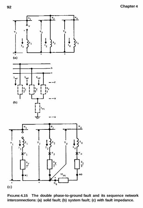
92 Chapter 4
+ (C)
FIGURE 4.15 The double phase-to-ground fault and its sequence network interconnections: (a) solid fault; (b) system fault; (c) with fault impedance.
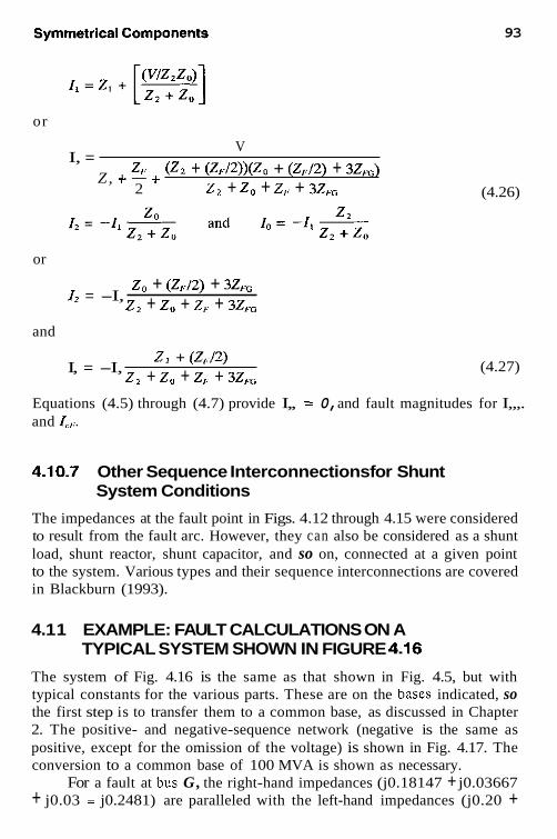
93
or
V I, = z,; (Z, + (Z,:/2))(Zo + (Z,J2) + 32,)
2 z2 + z, + z, + 3z,, Z, + - +
or
zo + (Z,:/2) + 3z,, z2 + zo + z, + 3z,.0 I2 = -I,
and
zz + (ZJ2) z2 + Z" + z,: + 3z,, I, = -I,
(4.26)
(4.27)
Equations (4.5) through (4.7) provide I,, = 0, and fault magnitudes for I,,,. and Jc, .
4.10.7 Other Sequence Interconnections for Shunt System Conditions
The impedances at the fault point in Figs. 4.12 through 4.15 were considered to result from the fault arc. However, they can also be considered as a shunt load, shunt reactor, shunt capacitor, and so on, connected at a given point to the system. Various types and their sequence interconnections are covered in Blackburn (1993).
4.1 1 EXAMPLE: FAULT CALCULATIONS ON A TYPICAL SYSTEM SHOWN IN FIGURE 4.16
The system of Fig. 4.16 is the same as that shown in Fig. 4.5, but with typical constants for the various parts. These are on the bases indicated, so the first step is to transfer them to a common base, as discussed in Chapter 2. The positive- and negative-sequence network (negative is the same as positive, except for the omission of the voltage) is shown in Fig. 4.17. The conversion to a common base of 100 MVA is shown as necessary.
For a fault at bus G, the right-hand impedances (j0.18147 + j0.03667 + j0.03 = j0.2481) are paralleled with the left-hand impedances (j0.20 +

94 Chapter 4
" BUS 23Okv t- Faul t
x"m=5. 5 %
xML=28\ XwL=16%
FIGURE 4.16 Power system example for fault calculations.
N 1 Values In Per Unit A t 1OOHVA
11.0 6 'P
j.03
1.0 = j . 03667
FIGURE 4.17 Positive and negative-sequence networks and their reduction to a single impedance for a fault at bus G in the power system of Fig. 4.16.

Symmetrical Components 95
j0.1375 = j0.3375). Reactance values, rather than impedance values, are used, as is typical when the resistance is relatively quite small.
(0.5763) (0.4237) 0.3375 X 0.2481
0.5856 x, = x, = = j0.1430 pu (4.28)
The division of 0.337Y0.5856 = 0.5763 and 0.2481/0.5856 = 0.4237, as shown, provides a partial check, for 0.5763 + 0.4237 must equal 1.0, which are the distribution factors indicating the per unit current flow on either side of the fault. These values are added to the network diagram. Thus, for faults at bus G, X, = X, = j0.1430 pu on a 100-MVA base.
The zero-sequence network for Fig. 4.16 is shown in Fig. 4.18. Again the reactance values are converted to a common 100-MVA base. The three- winding hank connections are as indicated in Fig. A4.2-3h with Z,, = Z,,, = 0 because the neutrals are shown solidly grounded.
The conversions to a common 100-MVA base are shown, except for the three-winding transformer. For this hank,
100 150
X,,, = 0.055 X - = 0.03667 pu
100 150
XHL = 0.360 X - = 0.2400 pu
100 150
X,, = 0.280 X - = 0.18667 pu
and from Eq. (A4.2-13) through (A4.2-15),
V a l Y e S I" Per ""it at l0Ormli
N o
j.1950 " 5 1 7 ,. 1.375
G
+.I701
FIGURE 4.18 Zero-sequence network and its reduction to a single impedance for a fault at bus G in the power system of Fig. 4.16.

96 Chapter 4
X, = i(0.03667 + 0.2400 - 0.18667) = 0.0450 PU
X, = t(0.03667 + 0.18667 - 0.240) = -0.00833 pu
X, = t(0.2400 + 0.18667 - 0.3667) = 0.1950 pu
(4.29)
These are shown in Fig. 4.18
Z , with Z , and then adding Z, and X,,,; This network is reduced for a fault at bus G by first paralleling X,, +
(0.6964) 10.3036) , \
0.1950 X 0.0850 0.280
= j0.0592 -i0.0083 (Z,) . ,
j0.620 (XwH) 10.6709
~
This is the right-hand branch. Paralleling with the left-hand branch,
(0.8299) (0.1701) 0.6709 X 0.1375
0.8084 x, = = j0.1141 pu at 100 MVA (4.30)
The values (0.8299) and (0.1701) shown add to 1.0 as a check and provide the current distribution on either side of the bus G fault, as shown on the zero-sequence network. The distribution factor 0.1701 for the right side is further divided up by 0.6964 X 0.1701 = 0.1184 pu in the 230-kV system neutral, and 0.3036 X 0.1701 = 9.0517 pu in the three-winding transformer H neutral winding. These are shown on the zero-sequence network.
4.1 1 .I Three-Phase Fault at Bus G
For this fault,
j l .0 10.143
I , = In* = 7 = 6.993 pu
100,000 = 6.993 = 3510.8 A at 115 kV d? x 115
The divisions of current from the left (ZuG) and right (Iap,) are:
IaG = 0.4237 X 6.993 = 2.963 pu
IaH = 0.5763 X 6.993 = 4.030 pu
(4.31)
(4.32)
(4.33)

Symmetrical Components
4.1 1.2 Single-Phase-to-Ground Fault at Bus G
For this fault,
97
j l .0 ~(0 .143 + 0.143 + 0.1141)
I, =I, = lo = . = 2.50 pu (4.34)
(4.35) I.,: = 3 X 2.5 = 7.5 pu at 100 MVA
loo'ooo = 3764.4 A at 115 kV ~ X 115
= 7.5 x
Normally, the 31, currents are documented in the system, for these are used to operate the ground relays. As an aid to understanding, these are illustrated in Fig. 4.19 with the phase currents. Equations (4.5) through (4.7) provide the three-phase currents. Because X, = X,, such that Il = I,, these reduce to Ib = I, = -I, + lo for the phase b and c currents, since a + uz = -1. The currents shown are determined by adding I, + I , +I, for I., -I, + la for Ih and I., and 310 for the neutral currents.
In the 115-kV system the sum of the two neutral currents is equal and opposite the current in the fault. In the 230-kV system the current up the neutral equals the current down the other neutral.
The calculations assumed no load; accordingly, prefault, all currents in the system were zero. With the fault involving only phase a, it will be observed that current flows in the b and c phases. This is because the dis- tribution factors in the zero-sequence network are different from the positive- and negative-sequence distribution factors. On a radial system where posi-
, , S t " 210t" Transformer B Y 5 c LLne BUS H T r a n s f o r m e r system
6
Per ""it currents at 100 WP..
FIGURE 4.19 Phase and 31, current distribution for a single-phase-to-ground fault at bus G in Fig. 4.16.

98 Chapter 4
tive-, negative-, and zero-sequence currents flow only from one source and in the same direction, the distribution factors in all three networks will be 1.0, although the zero-sequence impedances are different from the positive- sequence impedances. Then Ih = I, = -I, + I o becomes zero, and fault current flows only in the faulted phase. In this type I. = 31, throughout the system for a single-phase-to-ground fault.
4.12 EXAMPLE: FAULT CALCULATION FOR AUTOTRANSFORMERS
Autotransformers have become quite common in recent years. They provide some different and interesting problems. Consider a typical autotransformer in a system, as shown in Fig. 4.20, and assume that a single-phase-to-ground fault occurs at the H or 345-kV terminal. The first step is to set up the sequence networks with all reactances on a common base, which will be 100 MVA. The 161- and 345-kV system values are given on this base. For the autotransformer, the equivalent network is as in Fig. A4.2-3d, with values as follows: On a 100-MVA base,
100 150
X,,, = 8 X - = 5.333% = 0.05333 pu
100 50
X,,, = 34 X - = 68% = 0.68 pu (4.36)
100 40
X,, = 21.6 X - = 54% = 0.54 pu
and from Eq. (A4.2-13) through Eq. (A4.2-15),
X, = t(0.0533 + 0.68 - 0.54) = 0.09667 pu
X, = i(0.0533 + 0.54 - 0.68) = -0.04334 PU (4.37)
X, = i(0.68 + 0.54 - 0.0533) = 0.58334 pu
These values are shown on the sequence diagrams of Fig. 4.20. In the pos- itive- (and negative)-sequence networks for a fault at H,
(0.5796) (0.4204) (0.0533 + 0.057)(0.08) . x, = x, = = ~0.04637 pu
0.1903 (4.38)

Symmetrical Components 99
I- -
1 . 0 3 2
-,.(I*,, 1 . 0 9 6 7
. 7 8 2 0 ,
FIGURE 4.20 Example of fault calculation for an autotransformer.
100 Chapter 4
The zero-sequence network reduces as follows: first paralleling the left side,
(-0.0198)(1.0198) (0.032 - 0.0433)(0.5833) - (-0.0113)(0.5833) 0.032 - 0.0433 + 0.5833 0.5720
- - -
= -0.01156 pu
10.2331Y0.7669\ ,\
(4.39) (-0.01156 + 0.09667)(0.28) - (0.08511)(0.28) - 0.36511
x, = 0.08511 + 0.28
= j0.06527 pu
The current distribution factor through the X, path is 0.7669 X 1.0198 = 0.78207, and through the X, path is 0.7669 X -0.0198 = -0.01519. These current distributions are shown on the network.
4.12.1 Single-Phase-to-Ground Fault at H Calculation 1.0
0.1580 -~ - j l .0
I , = I , = I - " -J(O.O464 + 0.0464 + 0.0653) = 6.3287 pu (4.40)
loo'ooo = 1059.1 A at 345 kV v3 x 345 = 6.3287 X
Iefi = 31" = 3 X 6.3287 = 18.986 pu (4.41) = 3 X 1059.1 = 3177.29 A at 345 kV
It is recommended that amperes, rather than per unit, be used for fault current distribution, particularly in the neutral and common windings. The autotransformer is unique in that it is both a transformer and a direct elec- trical connection. Thus, amperes at the medium-voltage base I , are com- bined directly with amperes at the high-voltage base I H for the common winding current I, or for the high-side fault,
I = I,, (in amperes at kV,) - I , (in amperes at kV,) (4.42)
For the current in the grounded neutral,
310 = 310, (in amperes at kV,) - 31,, (in amperes at kV,) (4.43)
Both of the foregoing currents are assumed to flow up the neutral and to the M junction point.
Correspondingly, for a fault on the M or medium-voltage system, the current flowing up the grounded neutral is,

Symmetrical Components 1 o1
31, = 310, (in amperes at kV,) - 31," (in amperes at kV,) (4.44)
Thus, these currents in the common winding and neutral are a mixture of high- and medium-voltage currents; therefore, there is no base to which they can be referred. This makes per unit difficult, as it must have a base. When or if per unit must be used, a fictional base can be devised based on the transformer parts' ratios. This is quite complex. Being fundamental, am- peres are easy to handle and will be used in the following.
The sequence, phase a, and neutral currents are documented in Fig. 4.21 for the example of Fig. 4.20. There will be a current flowing in phases b and c because the current distribution factors are different in the positive- and zero-sequence networks. These are not shown, for they are of little importance in protection.
The example indicares that current flows down the autotransformer neutral instead of up, as might he expected. Ais0 in this example, the current in the delta has reversed, because the negative branch of the transformer- equivalent circuit is larger than the very solidly grounded 161-kV connected system. Both of these effects influence the protection, and this is discussed in Chapter 12.
amperes at 345kV i = I = 4 2 0 4 ~ 1 0 5 9 . 1 = 4 4 5 . 2 4 11=12= .5796x1059 .1=61) .85
I O H = . 7 6 6 9 x 1 0 5 9 . 1 = E 1 2 . 2 2 1 = 2 3 3 1 ~ 1 0 5 9 . 1 = 2 4 6 , 8 8 111 2H .
+ F O - ,, I*"=1702.7 I a = 1 4 7 4 . 5 9 amperes at 161kV
Y
1 4 0 . 6 4
"&.,
5 3 2 4 . 7
Inside Tertiary amperes at 13.8kV Total Total
From Down to GrOUnd Ground 5324.7 3177 .29 l0=-. 0 1 5 1 9 ~ 1 0 5 9 . 1 740 .64 2888 .04 G ü s x 3 T 6 0 6 5 . 3 3 =-232 .21
6 1 3 . 8
FIGURE 4.21 Fault current distribution for the autotransformer of Fig. 4.20.

102 Chapter 4
I, 345kV
1980.4
Ampere-turns up = Ampere-turns Down 1702.7~1.1429 + 231.21~ .i185 = 1980.4~1.0
1980.5 = 1380.4 Check. 1946.02 t 34.40 = 1980.4
FIGURE 4.22 Ampere-turn check to confirm or establish the direction of cur- rent flow in the tertiary.
There can be a question about the direction of current in the tertiary. This can be checked by ampere-turns, as shown in Fig. 4.22. Arbitrarily, one per unit turn was assumed for the 161-kV winding, and the others were derived. Any winding or group could be used for the base, as convenient.
4.13 EXAMPLE: OPEN-PHASE CONDUCTOR
A blown fuse or broken conductor that opens one of the three phases rep- resents a series unbalance covered in more detail in Blackburn (1993). As
G H 1 ] F::F ZIGH= . 2 1 W system
ZOGH= . 6 4 e 90% P.F.
31.5 kv 5OMVA Per Unit at 30 MVA
&Q -
0-8 i Xlr=X2s=15% D ,&
50MVA 30 MVA 115: 34.5 k V X = 8 % XTG= 1Q 3TH5: 13.8kV
FIGURE 4.23 Example for series unbalance calculations.

Symmetrical Components 103
Per Unit on 30 MVR - N1
6 5 1 + v- 1.286-*
1.0
s . 0 6 8 4 + j , 1 9 8 6 c =j . 0 4 2 IIG
1G = xis + X~~ + 'IGH 'i~= 'TH + 'LI = . 9 + 1.5159 = 1.031 ps.sZa = . 0 6 4 8 + j.3306 = .3369- PU
z =x +X +z b 1 2 G 2G IS TG IGH
='IG z = XTH + ZL2 2H =.5248 + j.3809 =.6426-
N O -
- - - - X Y
= . 2 5 0 + j . 5 8 9
'OG= 'TG + 'OGH = . 2 5 0 + j.631= . 6 7 8 8 m o p u
FIGURE 4.24 The three-sequence networks for the system of Fig. 4.23

FIGURE 4.25 Per unit current distribution far a n open conductor in power system of Fig. 4.23 (per unit at 30 MVA where 1 pu = 502 A at 34.5 kV).
an example, consider phase a open on the 34.5-kV line at bus H in Fig. 4.23. All constants are in per unit on a 30-MVA base.
The three sequence networks are shown in Fig. 4.24. With no-load, opening any phase makes no difference in the current flow because it is already zero. Consequently, in these series unbalances, it is necessary to consider load; therefore, the 30-MVA, 90% is as shown. With induction motor loads, the negative-sequence load impedance is less than the positive- sequence impedance. This is covered in Chapter 11.
If we assume the voltage at the load is 1.0 0" pu, then the voltage at the generator will be 1.286 15.315'. Phase a open is represented by con- necting the three-sequence X points together and the three-sequence Y points together. This connects the total zero-sequence impedances in parallel with the total negative-sequence impedances across the open X-Y of the positive- sequence network. From this, I,, I,, and I, can be easily calculated.
The resulting currents flowing in the system are shown in Fig. 4.25 and are in the order of normal load currents. Thus, it is difficult to locate and provide protection for these faults.
4.14 EXAMPLE: OPEN PHASE FALLING TO GROUND ON ONE SIDE
In the system of Fig. 4.23, the phase a conductor on the line at bus H opens and falls to ground value on the bus H side. The sequence networks

Symmetrical Components 105
H
Eqvivalent system
=1s=zzs 'TG
Phase a ' open L Grounded OD H Side 'TH
Ideal 1:l TransfoZmers
FIGURE 4.26 Example of the sequence network interconnections for phase a open and grounded at bus H (broken conductor has fallen to ground value).
are the same as in Fig. 4.24, hut are interconnected, as in Fig. 4.26. This is a simultaneous fault: a series open-phase fault and a phase-to-ground fault. Thus, three ideal or perfect transformers are used for isolation of the open-phase X-Y interconnection from three networks in series for the ground fault. Because these transformers have no leakage or exciting im-

I_ & = I.rsW59Q
10.74 b 7 m c c
3 b ~ i 3.11 &* w u m - - -
i 1.16 m930
- - - - - - FIGURE 4.27 Per unit current distribution for a broken conductor at bus H that falls to ground value on the bus H side in Fig. 4.23 power system. Top values are seen with a 30-MVA load. Values in parentheses are with load neglected (no load). Per unit is at 30 MVA where 1 pu = 502 A at 34.5 kV.
pedances, the voltage drop across them cannot be expressed by the current in their windings. I,, I,, and lo can be determined by solving various volt- age drop equations around the networks. The resulting fault currents are shown in Fig. 4.27. In this instance, it is possible to obtain currents by neglecting the load. These are shown in parentheses in Fig. 4.27.
The other possibility is that the open conductor falls to ground value on the line side. Here, the three ideal transformers are moved to the left or X side of the three-sequence networks: there is now no option-load must be considered. The fault currents are shown in Fig. 4.28.
Note that, as in the open phase (see Fig. 4.25), the currents are still quite low, not much higher than load currents.
4.15 SERIES AND SIMULTANEOUS UNBALANCES
Series and simultaneous unbalances do occur in power systems. One type is a blown fuse or open (broken) phase conductor. The broken conductor can contact ground making a simultaneous unbalance. Several examples of these are covered with examples in Blackburn (1993).
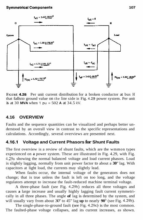
107
FIGURE 4.28 Per unit current distribution for a broken conductor at bus H that falls to ground value on the line side in Fig. 4.29 power system. Per unit is at 30 MVA when 1 pu = 502 A at 34.5 kV.
4.16 OVERVIEW
Faults and the sequence quantities can be visualized and perhaps better un- derstood by an overall view in contrast to the specific representations and calculations. Accordingly, several overviews are presented next.
4.16.1 Voltage and Current Phasors for Shunt Faults
The first overview is a review of shunt faults, which are the wmmon types experienced on a power system. These are illustrated in Fig. 4.29, with Fig. 4.29a showing the normal balanced voltage and load current phasors. Load is slightly lagging, normally from unit power factor to about a 30" lag. With capacitors at light load, the currents may slightly lead.
When faults occur, the internal voltage of the generators does not change; that is true unless the fault is left on too long, and the voltage regulators attempt to increase the fault-reduced machine terminal voltage.
A three-phase fault (see Fig. 4.29b) reduces all three voltages and causes a large increase and usually highly lagging fault current symmetri- cally in all three phases. The angle of lag is determined by the system, and will usually vary from about 30" to 45" lag up to nearly 90" (see Fig. 4.29b).
The single-phase-to-ground fault (see Fig. 4 .29~) is the most common. The faulted-phase voltage collapses, and its current increases, as shown.

108 Chapter 4
FIGURE 4.29 Typical current and voltage phasors for common s h u n t faults: The fault currents are shown at 90' Jagging or for a power system where Z = X. During faults the load is neglected. (a) Normal balanced system; (b) three-phase faults; (c) phase-to-ground a-Gnd faults; (d) phase-to-phase bc faults; (e) two phase-to-ground bc-Gnd faults.
Load current is neglected, for it usually is relatively quite small, and Ih =I, = 0. As has been indicated in the foregoing, fault current will flow in the unfaulted phases on loop systems in which the distribution factors for the three sequence networks are different. Again the fault current will lag nor- mally. It is shown at 90" in Fig. 4 .29~.
The phase-to-phase fault is seen in Fig. 4.29d. Neglecting load, for a b-to-c phase fault, V. is normal, I. = 0. V, and V, collapse from their normal position to vertical phasors at a solid fault point where V,, = 0. Ih and I, are normally equal and opposite and lagging 90" in Fig. 4.29d.
The two-phase-to-ground fault (see Fig. 4.29e) results in the faulted phase voltages collapsing along their normal position until, for a solid fault, they are zero. Thus, at the fault, V,, = V, = 0, which is not true for the phase- to-phase fault (see Fig. 4.29d). Ib and I, will be in the general area, as shown. An increasing amount of zero-sequence current will cause I , and I, to swiug closer to each other; contrarily, a very low zero-sequence current component

Symmetrical Components 109
Total Fault Current in Per Unit Based on V = jl pu; Z, = Z, = jl pu; and Z, = j X , pu
I, = 1.0 /m = 0.86V
Fault x, pu: 0.1 0.5 1 .o 2.0 10.0 10 Gnd 1.43 1.2 1 .o 0.75 0.25 00 Gnd 1.52 1.15 1 .o 0.92 0.87 31m G"d -2.5 -1.5 -1 .o -0.6 -0.143 Angle of Ima -145.29' -130.89" -120" -109.11" 94.69" Angle of I& Grid 145.29" 130.89" 120' 109.1 1" 94.69' "For the phase-to-phase fault: I, = - I , = 1/1 + 1 = 0.5. I& =a2/, + a / , = (a' - a)/, = - j d ( 0 . 5 ) = -j0.866.
FIGURE 4.30 Comparison of solid shunt-type faults
will result in the phasors approaching the phase-to-phase fault of Fig. 4.29d. This can be seen from the sequence network connections of Fig. 4.15. If Zo becomes infinite (essentially ungrounded system), the interconnection be- comes as in Fig. 4.14 for a phase-to-phase fault. On the other hand, for a very solidly grounded system where Z o approaches zero relatively, the neg- ative network becomes shorted, and this fault becomes similar to the three- phase fault of Fig. 4.12.
In some parts of a loop network it is possible for the zero-sequence current to flow opposite the positive- and negative-sequence currents. In this area I, may lag the V. phasor, rather than lead it as shown, with I , corre- spondingly leading the position shown.

110 Chapter 4
These trends are further amplified by Fig. 4.30, which compares the various solid shunt faults. The effect of the zero sequence for ground faults, is illustrated by various values of X, reactances relative to X, = X,. As has been indicated, the zero-sequence network is always different from the pos- itive- and negative-sequence networks. However, X, can be approximately equal to XI, X 2 for secondary bus faults on distribution feeders connected to large power systems. In these cases, the systems X, , X, are very small relative to the primary delta-secondary wye-grounded distribution trans- former. Thus, the case of X, = X, = X, is quite practicable.
4.16.2 System Voltage Profiles During Faults The trends of the sequence voltages for the various faults of Fig. 4.29 are illustrated in Fig. 4.31. Only the phase a sequence voltages are shown for an ideal case where Z, = Z2 = Z,. This makes the presentation less complex and does not affect the trends shown.
With the common assumption of no load, the system voltage is equal throughout the system, as indicated by the dashed lines. When a solid three- phase fault occurs, the voltage at the fault point becomes zero, hut as in- dicated earlier, does not change in the source until the regulators act to change the generator fields. By this time, the fault should have been cleared by protective relays. Thus, the voltage profile is as shown in Fig. 4.31a.
For phase-to-phase faults (see Fig. 4.31b), the positive-sequence volt- age drops to half value (Z , = Z 2 ) . This unbalance fault is the source of negative sequence and the V, drops are as shown, being zero in the generators.
For two-phase-to-ground faults (see Fig. 4 .31~) with 2, = Z2 = Z,,, the positive-sequence voltage at the fault drops to one-third of V,. The fault now generates both negative and zero sequence, which flows through the system, producing voltage drops as shown. V, becomes zero in the generators, whereas Vo is zero at the grounded transformer neutral point.
The fault voltage for a phase-a-to-ground solid fault is zero and as phase a is documented in Fig. 4.31d, the sum of the positive-, negative-, and zero-voltage components at the fault add to zero. Thus, the positive- sequence voltage drops to 2/3V, when Z, = Z, = Z , at the fault point, where -1/3V2 and -1/3Vo are generated. Again, they drop to zero in the generator or source for the negative sequence and to zero at the grounded transformer hank neutral.
The fundamental concept illustrated in Fig. 4.31 is that positive- sequence voltage is always maximum at the generators and minimum at the fault. The negative- and zero-sequence voltages are always maximum at the fault and minimum at the generator or grounded neutral.

Symmetrical Components
SOURCE TRANEFORllER TRINSFORILER SOURCE
111
FIGURE 4.31 System sequence voltage profiles during shunt faults: (a) three- phase faults; (b) phase-to-phase faults; (c) two-phase-to-ground faults; (d) phase-to-ground faults.

112
L a, 0 Q a,
3
z Q
0 0
m 0
- - ._ s a
Chapter 4
Y

Symmetrical Components 113
It is common to refer to the grounded-wye-delta or similar hanks as "ground sources." This is really a misnomer, as the source of zero sequence is the unbalance, the ground fault. However, so designating these transform- ers as ground sources is practical, for by convention ground (310) current flows up the grounded neutral, through the system, and down the fault into ground.
4.16.3 Unbalance Currents in the Unfaulted Phases for Phase-to-Ground Faults in Loop Systems
A typical loop system is illustrated in Fig. 4.32. A phase-a-to-ground fault occurs on the bus at station E, as shown in Fig. 4.33. The fault calculation was made at no-load; therefore, the current before the fault in all three phases was zero io all parts of the system. But fault current is shown flowing in all three phases. This is because the current distribution factors in the loop are different in the sequence networks. With X,, not equal to X, = X1; Ib = a21,
FIGURE 4.33 Currents for a phase-a-to-ground fault at station E bus of Fig. 4.32.

114 Chapter 4
+ a / , + lo = -I, + I,. Likewise, I, = -I, + I,. These are the currents Rowing in phases b and c in Fig. 4.33.
This will always occur in any system or part of a system in which there are positive-sequence sources or zero-sequence “sources” at both ends.
In ground fault studies, 31,, values should be recorded, because the ground relays are operated by 31,, not the phase-fault currents, which can be quite different, as seen in Fig. 4.33. Thus, there is little to no value in recording the phase values. These differences make fuse applications on loop systems quite difficult, because the fuse is operated on phase current, but the ground relays are on 310 currents.
For radial lines or feeders (positive-sequence source and a wye- grounded transformer at the same end, and no source or grounded trans- former at the other end) Ih and I , will be zero for all phase-a-to-ground faults. With the same phase and 310 ground currents, it is much easier to coordinate ground relays and fuses.
4.16.4 Voltage and Current Fault Phasors for All Combinations of the Different Faults
Another look at the sequence phasors is presented in Figs. 4.34 and 4.35: The voltages and currents generated by the sources can be only positive sequence by design, nothing else. Yet the unbalanced faults require unbal- anced quantities. How can this difference be resolved to satisfy both re- quirements: balanced quantities by the generators and unbalanced quantities at the faults? The resolution can be considered as the function of the negative-sequence quantities and for ground faults the zero-sequence quan- tities. This can be seen from Figs. 4.34 and 4.35. Considering the voltages of Fig. 4.34, voltage developed by the source or generator is the same for all faults. For three-phase faults no transition help is required because these faults are symmetrical; hence, there are no negative or zero sequences. For the phase-to-phasc faults, negative sequence appears to provide the transi- tion. Note that for the several combinations, ab, bc, and ca phases, the negative sequence is in different positions to provide the transition. The key is that for, say, an ab fault, phase c will be essentially normal, so V,, and V,, are basically in phase to provide this normal voltage. Correspondingly, for a bc fault, V,, and V,, are essentially in phase, and so on.
The two-phase-to-ground faults are similar; for ab-G faults, the unin- volved phase c quantities V,,, V,,, V,, combine to provide the uncollapsed phase c voltage. In the figure these are shown in phase and at half-magni- tude. In actual cases, there will be slight variations because the sequence impedances do not have the same magnitude or phase angle.

Sll

911

Symmetrical Components 117
Similarly for two-phase-to-ground faults; for an ab-G fault, Ir2 and I,, tend to cancel Ic,, and so on. For single-phase-to-ground faults the faulted phase components tend to add to provide a large fault current, because I,, + I',> + ISO = I..
4.17 SUMMARY
A question often asked is: Are the sequence quantities real or only useful mathematical concepts? This has been debated for years, and in a sense they are both. Yes, they are real; positive sequence certainly, because it is gen- erated, sold, and consumed; zero sequence because it flows in the neutral and ground and deltas; and negative sequence because it can cause serious damage to rotating machines. Negative sequence, for example, cannot be measured directly by an ammeter or voltmeter. Networks are available and commonly used in protection to measure V, and 12, but these are designed to solve the basic equations for those quantities.
In either event, symmetrical components analysis is an extremely val- uable and powerful tool. Protection engineers automatically tend to think in its terms when evaluating and solving unbalanced situations in the power system.
It is important to remember always that any sequence quantity cannot exist in only one phase; this is a three-phase concept. If any sequence is in one phase, it must be in all three phases, according to the fundamental definitions of Eqs. (4.2) through (4.4).
BIBLIOGRAPHY
See the Bibliography at the end of Chapter 1 for additional information.
Anderson, P. M., Analysis of Faulted Power Systems, Iowa State University Press, Ames, IA, 1973
ANSIAEEE Standard C37.5, Guide for calculation 01 fault currents for application of AC high voltage circuit breakers rated on a total current basis, IEEE Service Center.
Blackburn, J. L., Symmetrical Components for Power Systems Engineering, Marcel Dekker, New York, 1993.
Calabrese, G. 0.. Symmetrical Components Applied to Electric Power Networks, Ronald Press, New York, 1959.
Clarke, E., Circuit Analysis of A-C Power Systems, Vols. 1 and 2, General Electric, Schenectady Ny, 1943, 1950.
Harder, E. L., Sequence network connections for unbalanced load and fault condi- tions, Electr. J. Dec. 1937, pp. 481-488.
Standard 141-1993, IEEE Recommended Practice for Electric Power Distribution for industrial plants, IEEE Red Book, IEEE Service Center.

118 Chapter 4
Wagner, C. F. and Evans, R. D., Symmetrical Components, McGraw-Hill, 1933 (available in reprint from R. E. Krieger Publishing, Melbourne, FL, 1982).
APPENDIX 4.1 SHORT-CIRCUIT MVA AND EQUIVALENT IMPEDANCE
Quite often short-circuit MVA data are supplied for three-phase and single- phase-to-ground faults at various buses or interconnection points in a power system. The derivation of this and conversion into system impedances is as follows:
Three-Phase Faults
(A4.1-1)
where 13+ is the total three-phase fault current in amperes and kV is the system line-to-line voltage in kilovolts. From this,
*I,+ kV 1000
MVA,, = 34~ fault-short-circuit MVA =
lo00 MVA,, lh kV
1 3 , =
V , 1000 kV kVZ I?+ V%3+ MVAsr
-__ Z', = - = -
Substituting Eq. (2.15), which is
the positive-sequence impedance to the fault location is
(A4.1-2)
(A4.1-3)
(2.15)
(A4.1-4)
Z , = Zz for all practical cases. Z, can be assumed to be X , unless X/R data are provided to determine an angle.
Single-Phase-to-Ground Faults
(A4.1-5)
where Im0 is the total single-line-to-ground fault current in amperes and kV is the system line-to-line voltage in kilovolts.
kV MVA+,sc = 4 G fault short-circuit MVA = 1000

Symmetrical Components
1000 M V b s c kV
I* =
However,
3 V L N - - 3 VLN I,, = I , + I , + I , = - z, + z, + z, z,
where Z, = Z, + Z 2 + 2,. From Eqs. (A4.1-3) and (A4.1-7),
(in ohms) 3 kV2
MVAmcsc z, =
119
(A4.1-6)
(A4.1-7)
(A4.1-8)
(A4.1-9)
Then Zo = Z , - Z, - Z,, or in most practical cases, X, = X, - X, - X,, because the resistance is usually very small in relation to the reactance.
Example
A short-circuit study indicates that at bus X in the 69-kV system,
MVA,, = 594 MVA
MVbcsc = 631 MVA
on a 100-MVA base. Thus, the total reactance to the fault is
100 - 594
X, = X - - = 0.1684 pu
300 63 1
X, = - = 0.4754 pu
X, = 0.4754 - 0.1684 - 0.1684 = 0.1386 pu, all values on a 100-MVA69- kV base.
APPENDIX 4.2 IMPEDANCE AND SEQUENCE CONNECTIONS FOR TRANSFORMER BANKS
Two-Winding Transformer Banks
Typical hank:. are shown in Fig A4.2-1. H is the high-voltage winding and 1. the low-vol tqe winding. These designations can be interchanged as re- quired. ZT is thc trmhformer Ieak:tgc Impedance between the two windings.

120 Chapter 4
zero
Connection
FIGURE A4.2-1 banks.
Sequence connections for typical two-winding transformer

Symmetrical Components 121
It is normally designated in per unit or percent by the manufacturer and stamped on the transformer nameplate. Unless otherwise specified, this value is on the self-cooled kVA or MVA rating at the rated voltages.
It can he measured by shorting one winding and applying voltage to the other winding. This voltage should not cause the transformer to saturate. From Fig. A4.2-2,
(A4.2-1)
Because Z , unsaturated is very large compared to Z,, the term Z,Z,/Z, + Z. approaches and is approximately equal to Z,, so that for practical purposes
V z - - = Z , + Z , (A4.2-2)
Z T is measured in practice by circulating rated current (IR), through one winding with the other shorted and measuring the voltage (V,) required to circulate this rated current. Then,
r - I
(A4.2-3)
This test can he done for either winding, as convenient, On the measured side, the base impedance will he
v w Z , = - ohms I ,
(A4.2-4) VR
1, Z , = - ohms
where V, and I, are the rated voltage and current respectively. Then, the per unit impedance from Eq. (2.1) is
Z , in ohms V J , Vw Z , in ohms IRVR V, - PU Z T = - (A4.2-5)
For three-phase-type transformer units, the nameplate should specify this Z , usually in percent, on the three-phase kVA (MVA) rating, and the kV line-to-line voltages. When several kVA (MVA) ratings are specified, the normal rating, without fans, pumps, and such (lowest) rating, should be used as one of the impedance bases.
For individual single-phase transformers, the transformer impedance normally is specified on a single-phase kVA (MVA) and the rated winding voltages (kV) of the transformer. When three such units are used in three- phase systems, then the three-phase kVA (MVA) and line-to-line voltages (kV) bases are required, as outlined in Chapter 2.

122 Chapter 4
FIGURE A4.2-2 Simplified equivalent diagram for a transformer: Z, and Z, are the components of the transformer leakage impedance and Z. is the exciting impedance. All values in per unit or primary H side ohms.
Thus, when three individual single-phase transformers are connected in the power system, the individual nameplate percent or per unit impedance will he the Z, leakage impedance, but on the three-phase kVA (MVA) base, and the system line-to-line kV
Example: Impedances of Single-Phase Transformers in Three-Phase Power Systems
Consider single-phase transformers, each with a nameplate rating of 20 MVA, 66.5 kV13.8 kV, X = 10%. Considering the individual transformer alone, its leakage reactance is
X, = 0.10 pu on 20 MVA, 66.5 kV
X, = 0.10 pu on 20 MVA, 13.8 kV
or (A4.2-6)
Converting these to actual ohms using Eq. (A4.2-5); V,, = 0.10 V,,, = 0.10 X 66,500 = 6650 volts on the high side, where In" = 20,000166.5 = 300.75 amperes primary.
Then, from Eq. (A4.2-3),
(A4.2-7)
or on the secondary side, V, = 0.10 X 13,800 = 1380 volts, and IRL = 20,000/13.8 = 1449.28 amperes secondary.
6650 300.75
x,=-- - 22.11 ohms primary
- 0.952 ohm secondary 1380
1449.28 x
TL -
Check
(A4.2-8)
($)i X 0.952 = 22.11 ohms primary

Symmetrical Components 123
Now consider two possible applications of three of these individual transformers to a power system. These are intended to demonstrate the fun- damentals and do not consider if the transformer windings are compatible or suitable for the system voltages shown.
Case 1
Connect the high-voltage windings in wye to a 115-kV system and the low- voltage windings in delta to a 13.8-kV system. As indicated previously, the leakage impedance of this transformer bank for this application is
X, = 0.10 pu on 60 MVA, 115 kV
X , = 0.10 pu on 60 MVA, 13.8 kV (A4.2-9)
Now to check this. From Eq. (2.17),
115’ X 0.10 60
= 22.11 ohms primary X, = (A4.2-10)
13.8’ X 0.10 60
= 0.317 ohm secondary X T L =
It will be noted that the individual transformer reactance per Eq. (A4.2-8) is 0.952 ohm, but this is the reactance across the 13.8 kV because of the delta connection. The equivalent wye impedance can be determined by the product of the two-delta branch on either side of the desired wye branch divided by the sum of the three-delta branches. Thus, the wye equivalent is
(0.952)0.952 0.952 - - 0.317 ohms as before (3)0.952 3
Check
(%)* X 0.317 = 22.1 ohms primary
Case 2 Connect the high-voltage windings in delta to a 66.5-kV system, and the low-voltage side in wye to a 24-kV system. Now the transformer bank im- pedance for this system application is
X, = 0.10 pu on 60 MVA, 66.5 kV
X, = 0.10 pu on 60 MVA, 24 kV
or (A4.2-11)
Now to check this by converting to ohms, using Eq. (2.17)
66.5‘ X 0.10 60
= 7.37 ohms primary XT” = (A4.2-12)

124 Chapter 4
Now this primary winding of 22.11 ohms [Eq. (A4.2-7)] is connected across the 66.5-kV system because of the delta. Accordingly, the equivalent wye reactance is 22.11 X 22.1113 X 22.11 = 7.37 ohms line-to-neutral on the primary side.
On the secondary side, X,, = 242 X 0.10/60 = 0.952 ohm secondary as Eq. (A4.2-8).
Check
(F)' X 0.952 = 7.37 ohms primary
The connections of two-winding transformers in the sequence networks are documented in Fig. A4.2-1. Note that the connections for positive and negative sequences are all the same and are independent of the bank con- nections. This is not true for the zero sequence with different connections for each type of bank.
Neutral impedance is shown for several connections. If the banks are solid-grounded, the neutral impedance is zero, and the values shown are shorted-out in the system and zero-sequence diagrams.
Three-Winding and Autotransformer Banks
Typical banks are shown in Fig. A4.2-3. H, M, and L are the high., medium-, and low-voltage windings. These designations can be interchanged as required. Normally, the manufacturer provides the leakage impedances between the windings as ZHM, Z,,, and Z,,, usually on different kVA or MVA ratings and at the rated winding voltages.
To use these impedances in the sequence networks, they must be con- verted to an equivalent wye-type network, as shown. This conversion is
z, = +(Z", + z,, - ZML)
z, = t(ZH, + z,, - Z,,,)
(A4.2-13)
(A4.2-14)
It is easy to remember this conversion, for the equivalent wye value is always half the sum of the leakage impedances involved, less the one not involved. For example, Z, is half of Z,,, and Z,,, both involving H, minus Z,,. that does not involve H.
After determining ZH, Z,, and ZL, a good check is to see if they add up as Z,, + Z, = Z,,,, _ _ _ _
If these values are not available, they can be measured as described for a two-winding transformer. For the three-winding, or autotransformers:

125
Transformer Bank
COnnecrio"
+*" - '""Q
aL
P o s i t i v e and Negarlve sequence
connection
N. Or N,
2 WI or N
H
<L n
N1 or N2
XL w
I zero sequence
Connection
f Solid rounded
! S o l i d -ounded ," and/or ZWH=O
N"
FIGURE A4.2-3 Sequence connections for typical three-winding and auto- transformer banks.
Z,, is the impedance looking into H winding with M shorted, L open; Z,, is the impedance looking into H winding, with L shorted, M open; Z,, is the impedance looking into M winding, with L shorted, H open.
This equivalent wye is a mathematical network representation valid for determining currents and voltages at the transformer terminals or in the

126 Chapter 4
associated system. The wye point has no physical meaning. Quite often, one of the values will be negative and should be used as such in the network. It does not represent a capacitor.
The positive- and negative-sequence connections are all the same and independent of the actual bank connections. However, the connections for the zero-sequence network are all different and depend on the transformer bank connections. If the neutrals are solidly grounded, then the Z, and 3ZN components shown are shorted-out in the system and sequence circuits.
APPENDIX 4.3 SEQUENCE PHASE SHIFTS THROUGH WE-DELTA TRANSFORMER BANKS
As has been indicated, positive and negative sequences pass through the transformer bank, and in the sequence networks, the impedance is the same independently of the bank connection. This is shown in Figs. A 4 2 1 and A4.2-3. In these networks the phase shift is ignored, but if currents and voltages are transferred from one side of the transformer bank to the other, these phase shifts must be taken into account. This appendix will document these relations. For this the standard ANSI connections are shown in Fig. A4.3-1.
From Fig. A4.3-la, all quantities are phase-to-neutral values, and in amperes or volts; for per unit, N = I, n = 1/V'5.
I A = n(l, - I,) and V, = n(V, ~ Vn)
For positive sequence [see Eq. (4.2)],
I,,> = n ( L - aL,) = n(1 - a)Io,
= v3nIa , /-3o" = NI", LS V,, = n(v,, - a'v,,) = n(1 - a')V,,,
= d7nv,,/+30" z ~~,,,/+30" For negative sequence [see Eq. (4.3)],
r,,> = n(Zol - a2zal) = n(l - a2&,
= d7nza2& = NI,,&
V., = n(V,, - aV,,) = n(1 - a)V,,
= d 7 n v A , / 3 0 " = ~v;,/30"
(A4.3-1)
(A4.3-2)
(A4.3-3)
(A4.3-4)
(A4.3-5)

Symmetrical Components 127
LOU S i d e (b) H i g h S i d e Law S i d e ( 8 ) Hiqh S ide
T U Z ~ S Ratio n:l Voltaae Ratio N:l
" = .Ji
TYrnS Ratio n : 1 Voltage Raeio N: l
fl kVa
FIGURE A4.3-1 ANSI-connected we-delta transformer banks: The high- voltage side phase a leads the low-voltage side phase a for both connections illustrated: (a) wye (star) on high side; (b) delta on high side.
Now consider the connections in Fig. A4.3-lb. Again all values are in phase-to-neutral amperes or volts; for per unit, N = 1, n = d 3 .
1 1 n n I, = - (1" - I,,) and V, = - (V. - V,)
For positive sequence [see Eq. (4.2)],
1 1 n
= ; (IAl - aV,,,) = - (1 - a')l,,, (A4.3-6)

128 Chapter 4
(A4.3-7)
For negative sequence [see Eq. (4.3)],
1 1 n n (A4.3-8)
= - (Inl - UI,J = - (1 - uyA2
1 1 n n (A4.3-9)
v,, = - (V& - U'V.,) = ~ (1 - U')V"?
= a vo,@ = - 1 v,,/+30" n N
Summary An examination of the foregoing equations shows that for ANSI standard connected wye-delta transformer banks: (1) if both the positive-sequence currenf and voltage on one side lead the positive-sequence current and volt- age on the other side by 30", the negative-sequence current and voltage correspondingly will both lag by 30"; and (2) similarly, if the positive- sequence quantities lag in passing through the bank, the negative-sequence quantities correspondingly will lead 30". This fundamental is useful in trans- ferring currents and voltages through these hanks.
Zero sequence is not phase-shifted if it can pass through and flow in the transformer bank. The zero-sequence circuits for various transformer banks are shown in Figs. A4.2-1 and A4.2-3.

Relay Input Sources
5.1 INTRODUCTION
Protective relays require reasonably accurate reproduction of the normal, tolerable, and intolerable conditions in the power system for correct sensing and operation. This information input from the power system is usually through current and voltage transformers. An exception is for temperature- type relays, which receive their information from thermocouples or temper- ature indicators.
These devices-current transformers (CTs), voltage transformers (VTs, formerly PTs), and coupling capacitor voltage transformers (CCVTs) -provide insulation from the higher-system voltages and a reduction of the primary current and voltage quantities. Thus, the transformer primary source is connected into or to the power system with insulation that is compatible with that of the system. The secondary source is standardized for the con- venience of application and relay design. These relay input sources are an important member of the protection “team.” Typical units are illustrated in Figs. 5.1 through 5.5, and also see Fig. 1.8.
Other means of providing power system information for protective relays are being developed and finding applications. One is the magneto- optic current transducer. This uses the Faraday effect to cause a change in light polarization passing through an optically active material in the presence
129

130 Chapter 5
FIGURE 5.1 Typical low-voltage current transformers: (a) bar type, with the bar as the primary: (b) through type, where the primary cable is passed through the CT opening. (Courtesy of Westinghouse Electric Corporation.)
of a magnetic field. The passive sensor at line voltage is connected to station equipment by fiber-optic cable. This eliminates supports for lieavy iron cores and insulating fluids.
The output is low-energy and can be used with microprocessor relays and other low-energy equipment. These are most useful at the higher volt- ages using live tank circuit breakers that require separate CTs.

Relay Input Services 131
FIGURE 5.2 A 230-kV oil-filled current transformer. The unit is approximately 10 ft high and 2.5 ft in diameter. (Courtesy of Westinghouse Electric COrpO- ration.)
In the meantime iron-cored devices are ubiquitous in power systems and do not appear to be easily replaced.
The intolerable system problems may be transient or permanent, and may involve a change in the primary current or voltage over a wide range. This is particularly true for the current, which can suddenly change from a few amperes to several hundred amperes secondary when a fault occurs. Voltages during faults can collapse, from the rated value down to zero.

132 Chapter 5
FIGURE 5.3 Voltage transformer for use in low-voltage power systems. (Courtesy of Westinghouse Electric Corporation.)
5.2 EQUIVALENT CIRCUITS OF CURRENT AND VOLTAGE TRANSFORMERS
The equivalent diagrams for an instrument transformer are shown in Fig. 5.6. The cxciting (magnetizing impedance Z.. in Fig. 5.6a is shown in two parts: Z: is that associated with the leakage flux within the transformer core and its related leakage reactancc X; Zl is that associated with thc flux that does not reach the core. X , is the leakage reactance from this flux that does not cut the transformer core. R,, and R, are the resistances of the primary and secondary windings, respectively.
For voltage transformers, the value of (R, + R,) + j(X,, + X) is kept low to minimize the loss of voltage and shift of the phase angle from primary to secondary. Current transformers are of two types; those with significant leakage flux in the core (sce Fig. S.6a), and those with ncgligible leakage

Relay Input Services 133
FIGURE 5.4 Typical 115-kV switchyard with three 115-kV voltage transform- ers in the foreground. mounted on top of a 10-ft pipe. Behind are oil circuit breakers and in the right rear, a 325-MVA 230:l 15-kV autotransformer bank. (Courtesy of Puget Sound Power & Light Co.)
f lux in the core (see Fig. 5.6b). In either type the Z. shunt impedance() are kept high to minimize current loss from the primary to the secondary.
The perfect or ideal transformers shown in the diagrams are to provide the necessary ratio change; they have 110 losses or impedance. Although sliown in the primary, they may be connected in the secondary instead. As shown, all the impedances are o n a secondary basis. With per unit nomen- clature, the perfect transformers are omitted, because they are not required.
The primary quantities are reduced by the turns ratio n to provide a secondary current o r voltage to energize protective relays and other equip- ment. The impedances of these loads are commonly called burden. The term can refer to individual devices, or to the total load connected, including the instrument transformer secondary impedance when that is significant. For the devices, the burden is often expressed in volt-amperes at a specified current or voltage. Thus, for CTs or VTs the burden impedance Z,, is
VA V' Z,, = - ohms (for CTs) or = ~ ohms (for VTs) (5.1) I' VA
where VA i s the volt-ampere burden and I or V the amperes or volts at which the burdcn was measured or specified.

134 Chapter 5
FIGURE 5.5 A 500-kV coupling capacitor voltage transformer undergoing fac- tory test and calibration. (Courtesy of Westinghouse Electric Corporation.)
5.3 CURRENT TRANSFORMERS FOR PROTECTION APPLICATIONS
Current transformers almost universally have 5-A secondary ratings. Other ratings, such as 1 A, exist, hut are not common, although they are used in other countries: Advantages for this lower rating may exist when unusually long secondary leads are required between the CTs and the relays, such as in high-voltage (HV) installations. However, changing the current trans- former rating does not necessarily reduce the energy required for relay op-

Relay Input Services 135
(dl Perfect Transformer
d l p For Ratio O n l y
d f i :" for CT's n : l for V T ' s
1b1 Perfect
x t X I Transformer
e For Ratio Only Rp P - ?-Jy sec.
- h 1:" d f 11
FIGURE 5.6 Equivalent diagrams for instrument transformers: With perfect (ideal) transformers for ratio primary to secondary as shown. the values are in secondary ohms (n = turns). With per unit, omit the perfect transformers. (a) For significant leakage flux in transformer core-class T CTs and voltage transformers; (b) for negligible leakage flux in transformer core-class C CTs.
eration. With a constant VA, lower current means higher voltage and more insulation between the primary and the secondary. For the most part, the advantages appear to be offset by the disadvantages. Today and in the future, solid-siate microprocessor relays, with very low burdens, make the need for another standard less useful.
The measure of a current transformer performance is its ability to re- produce accurately the primary current in secondary amperes both in wave shape and magnitude. There are two parts: (i) the performance on the sym- metrical ac component, and (2) the performance on the offset dc component. Modern CTs do a remarkable job of reproducing wave shapes as long as they do not saturate.
5.4 CURRENT TRANSFORMER PERFORMANCE ON A SYMMETRICAL AC COMPONENT
For the symmetrical component the performance is determined by the high- est curreni that can be reproduced, without saturation, to cause large ratio errors. Phase-angle errors are not usually critical for relaying.
If the CT does not saturate, it is practicable to assume that I , is negligible.

136 Chapter 5
(5.2) 1, R,
I, = - amperes or 1, = Ip per unit
where R, is the current transformer ratio and equivalent to n in Fig. 5.6. For CTs connected in the phase leads of the power system with load
passing through them, the ratio R, is selected so that the maximum antici- pated secondary current does not exceed 5-A secondary. This comes from the long-standing practice of indicating instrument movements being stan- dardized at 5 A, independently of the primary ampere scale markings. By selecting a ratio to give a little less than 5 A at the maximum load, any instrument connected in the circuit would not go off scale. Instruments may or may not be connected in the relay circuits, hut this practice continues, with the continuous ratings of the CTs and relays often based on 5 A.
However, I,, the CT-exciting current, is never zero if the CT is ener- gized either by the primary or on the secondary current. Thus, it must he checked to assure that it is negligible. This can be done by one of three methods: (1) classic transformer formula, (2) CT performance curves, or (3) ANSUIEEE accuracy classes for relaying.
5.4.1 Performance by Classic Analysis
The classic transformer formula is
V , = 4.44 fNAP,,. X lo-' volts (5.3)
where f is the frequency in hertz, N the number of secondary turns, A the iron-core cross-sectional area in square inches, and Pmrx the iron-core flux density in lines per square inch. However, most of these quantities are not normally available, so this method is used primarily by CT designers. V , is the voltage the current transformer can develop to drive secondary current through the load.
This load on the CTs consists of its secondary resistance RC, the im- pedance of the connecting leads Z,,, and the equipment (relays and such) Z,. The voltage required by the burden (load) is
V , = Iy(Rs + 2, + Z,) volts (5.4)
5.4.2 Performance by CT Characteristic Curves
The calculation of the performance with the equivalent circuit of Fig. 5.6a is difficult, even when the value of X is known. The ANSUIEEE standard (C57.13) for instrument transformers recognizes this and classifies C T s that have significant leakage flux within the transformer core as class T (class H

Relay Input Services 137
before 1968). Wound (TTs, those that have one or more primary-winding turns mechanically encircling the core, are usually class T. Their perfor- mance is best determined by test, with the manufactures providing curves as shown in Fig. 5.7.
CTs constructed fo minimize the leakage flux in the core, such as the through, bar, and bushing types (see Fig. 5.1), can be represented by the modified equivalent circuit of Fig. 5.6b. Effectively, the leakage reactance X is ahead of the exciting branches, and these branches can be paralleled to Z,. With this the performance can be calculated. These are designated as class C (class L before 1968). Typical class C excitation curves are shown in Fig. 5.8 and see also Fig. 5.12.
The knee or effective point ofsaturation is defined by the ANSIDEEE standard as the intersection of the curve with a 45" tangent line. However, the International Electrotechnical Commission (IEC) defines the knee as the intersection of straight lines extended from the nonsaturated and saturated parts of the exciting curve. The IEC knee is at a higher voltage than the ANSI knee, as shown in Fig. 5.8.
FIGURE 5.7 Typical overcurrent ratio curves for class T current transformers. (Fig. 5 of ANSVIEEE Standard C37.13.)

138 Chapter 5
FIGURE 5.8 Typical excitation curves for a rnultiratio class C current trans- former: Point A is the ANSI knee. Above this line the voltage for a given exciting current for any unit will not be less than 95% of the curve value. Point B is the IEC knee. (Fig. 4 of ANSVIEEE Standard C57.13-1978)
5.4.3 Performance by ANSI/IEEE Standard Accuracy Classes
In many applications, the use of the ANSIDEEE accuracy class designa- tions is adequate to assure satisfactory relay performance. As indicated, there are two standard classes: class T, for which performance is not easy to calculate, so manufacturer’s test curves must be used (see Fig. 5.7); and class C, for which the performance can be calculated These designitions are followed by a number indicating the secondary terminal voltage (V,) that the transformer can deliver to a standard burden at 20 times the rated secondary current without exceeding the 10% ratio correction (Fig. 5.9). This 10% will not be exceeded at any current from 1 to 20 times the rated secondary current at the standard burden or any tower standard burden. For relaying, the voltage classes are 100, 200, 400, and 800, corresponding to standard burdens of B-1, B-2, B-4, and B-8, respectively. These burdens are

Relay Input Services 139
FIGURE 5.9 Secondary voltage capabilities for various class C current trans- formers.
at 0.5 power factor. The burden numbers are ohms, obtained by dividing the voltage rating by 20 times the rated secondary current. Thus, with the 800- V rating and its associated B-8 burden: 8 R X 5 A X 20 = 800 V.
If the current is lower, the burden can be higher in proportion; how- ever, this does not necessarily apply to higher currents because the internal impedance, basically neglected in the standard, can affect performance. Therefore, a 400-V rated CT will pass 100 A (20 times rated) with a burden of 4 Cl or less, with not more than 10% ratio error. Correspondingly, it can pass 50 A with an 8-R burden with not more than the 10% error.
For these voltage ratings, terminal voltage is used, rather than the excitation voltage of Eq. (5.4), or
v, = Z,(Z,,, + Z,) volts (5.5)
The lower-voltage classes of 10, 20, and 50 with standard burdens of B-0.1, B-0.2, and B-0.5 at 0.9 power factor are primarily for metering service and should be used very cautiously for protection.
Two similar CTs connected in the primary circuit, with the same ratio and their secondaries in series, will increase the accuracy capability. As an example, first consider a single 200/5 (Re = 40), with a total burden of 0.5 a. The primary current is 3200 A. Then the current through the relay (bur-

140 Chapter 5
den) will be 3200/40 = 80 A secondary, neglecting any saturation, and the CT must be capable of developing 80 X 0.5 = 40 V secondary.
Now, with two 200/5 CTs in the primary and their secondaries in series, 80 A will flow through the relays. The voltage across the relays will be 40 V, but each CT need develop only 20 V.
Two similar CTs, with their secondaries in parallel, provide an overall lower ratio with higher-ratio individual CTs and their correspondingly higher accuracy rating. For the foregoing example, use two 400/5 (Rc = 80) CTs instead of 200/5 CTs. Then the CI secondary current is 3200/80 = 40 A, but the current through the relays is 80 A and the voltage across the relays, and each CT is 40 V. This is the same voltage as that for the single CT, but now with the higher-accuracy class 400/5 CTs.
The use of two CTs may he quite helpful when low-ratio CTs are used because of low feeder loads, but the close-in fault current can be very high. The low CT accuracy can result in failure or poor operation of the protection.
It should be appreciated that the ANSI classifications merely indicate that the ratio correction or error will not exceed 10%; they do not provide information on the actual value, which may be any value, but not exceeding 10%. Also importantly, these accuracy class values apply only to the furl winding, and are reduced proporiionally when lower raps are availabre and used. Many type C transformers are bushing multiratio type, with five sec- ondary taps, providing ratios such as those shown in Fig. 5.9 (see also Fig. 5.11). Performance on these lower taps is significantly reduced and limited. As a general rule, the use of the lower-ratio taps should be avoided, and when used, the performance should be checked.
According to the standards, the manufacturer is to supply application data for relaying service of current transformers of (1) the accuracy class, (2) short-time mechanical and thermal ratings, (3) resistance(s) of the sec- ondary winding, and (4) typical curves, such as Fig. 5.7 for class T and Fig. 5.9 for class C (see also Fig. 6.4).
5.4.4 IEC Standard Accuracy Classes
The International Electrotechnical Commission (IEC) specifies the accuracy of current transformers as
15 VA Class 10 P 20
I I I L For protection I L Accuracy class L Continuous VA
I I L A c c u r a c y limit factor

Relay Input Services 141
Thus, for this CT rated at 5 A, 15/5 = 3 volts and will have no more than 10% error up to 20 X 3 = 60 volts secondary.
Standard values for relaying CTs are
Continuous V A Accuracy classes: 5 and 10% Accuracy-limit factor: Rated secondary amperes:
For a current transformer rated 30 VA class 10 P 30
2.5, 5, 10, 15, and 30
5, 10, 15, 20, and 30 1, 2, and 5 (5 A preferred)
30/5 = 6 volts; 6 X 30 = 180 volts
The permissible burden is 30/52 = 1.2 ohms. This is equivalent to an ANSI/ IEEE C180 current transformer.
5.5 SECONDARY BURDENS DURING FAULTS
The burden imposed on CTs for various faults and connections is docu- mented in Fig. 5.10. Z,, is the sum of the leads or connecting circuits he- tween the CIS and the relays, plus the relays and other equipment. It is assumed that the burden in each phase is the same, but this may not always he correct. When the CTs are connected in delta (see Fig. S.lOb), the burden on the phase A current transformer is (I,, - IB)ZB - (Ic - IA)Ze. This reduces to [U, - (IB + I&,. For a three-phase fault, I,, + IB + Ic = 0, so (Ie + Ic) = -I,,, and substituting this, the burden reduces to 31AZ,.
Because phase relays are set on three-phase fault currents, and ground relays are set on single-phase-to-ground fault currents, the phase-to-phase fault diagrams are not generally used. They do show that the burden is the same as for three-phase faults, and with less phase-to-phase fault current, the three-phase fault cases are the maximum.
5.6 CT SELECTION AND PERFORMANCE EVALUATION FOR PHASE FAULTS
A suggested process for selection of the CT ratio and evaluation of its per- formance can be shown by an example. Consider a circuit to be protected by overcurrent relays with the following load and fault levels;
Imarioad = 90 A
I ~ , ~ ~ ~ ~ ~ , ~ ~ = 2500 A
ImLn,u,t = 350 A

lined

Relay Input Services 143
FIGURE 5.10 Continued
current should be just under 5 A for the maximum load. This was because instruments were often in the same circuit, and they had 5-A movements. Following this practice, select the CT ratio of 100/5 (Rr = 20). This gives a maximum continuous secondary current, when the load is 90 A, of Is = 90/ 20 = 4.5 A.
5.6.2 Select the Relay Tap for the Phase-Overcurrent Relays
Overcurrent taps represent the minimum pickup or operating current of an overcurrent relay. Thus, a tap is chosen that is higher than the maximum load, in this example, above 4.5 A. How much higher is based on relay characteristics, experience, and judgment. There is no problem if a time overcurrent relay picks up on a cold load, offset currents, or other, provided these currents subside below the relay pickup before it operates. This may be required when the margin between minimum fault and maximum load is small.
Small tap 5 is selected. The ratio above load 5/4.5 = 1.1. This provides a small margin more than any potential increase in the continuous load, but a large margin with inverse-type relays for transient overcurrents, such as a cold load. Minimum fault of 350/20 = 17.5 A, and 17.515 = 3.5 times the minimum relay pickup that is desirable for any possible fault restriction.
If tap 6 were selected, then the margin above load is greater (6/4.5 = 1.33), but a smaller margin (17.516 = 2.9) above the relay pickup.

144 Chapter 5
5.6.3 Determine the Total Connected Secondary Load (Burden) in Ohms
The total connected secondary load determination must include all of the impedances between the CTs and the equipment (relays) in the phase circuit. Ground relays are discussed in Section 5.8. Data on the relays must be obtained from the manufacture for the particular type. The burdens of solid- state and microprocessor-type relays are very low and relatively constant with taps. For these applications the lead burden becomes the major load on the CTs.
Tap 5 will be used with electromechanical relays, for which the burden is 2.64 VA at 5 A and 580 VA at 20X (100 A). The leads from the CT to the relays are 0.4 R. Typical practice is to use number 8- or 10-sized leads for low resistance and to minimize mechanical damage to these important connections.
The total secondary impedance at pickup, adding directly:
Relay burden 2.64/5* = 0.106 R Lead resistance = 0.40 Cl Total to CT terminals = 0.506 R at 5 A
The total secondary impedance at 2OX (100 A), adding directly:
Relay burden 580/1002 = 0.058 R Lead resistance = 0.40 R Total to CT terminals = 0.458 R at 100 A
This is typical for electromechanical relays that tend to saturate at the higher currents. Thus, their internal impedance decreases and becomes more resistive. For these relays the manufacturer will supply burden data at several current levels. Such reduced burdens aid CT performance. Again burdens for solid-state relays are low and more constant at various current levels.
It is frequently practical to add the burden impedances and the currents algebraically, but theoretically they should be combined phasorally. If the performance is marginal, combine phasorally; otherwise, direct addition is satisfactory and simpler. This is done in this example.
Burdens are generally near unity power factor; hence, Is tends to be near unity power factor. However, I,, the exciting current lags 90", so com- bining I , and at right angles is a good approximation.

Relay Input Services 145
5.6.4 Determine the CT Performance Using the ANSIIIEEE Standard
When Using a Class T CT
Check the performance from the curve provided, such as Fig. 5.7. The “B” are standard burdens. The relay burdens are B1, B2, B3, B4, and B8. These are the total secondary load impedances to the terminals gh in Fig. 5.6a and would be the 0.506 or 0.458 values in the foregoing.
When Using a Class C CT and Performance by the ANSVIEEE Standard
For this example, a 600/5 multiratio CT with ClOO rating had been prese- lected. With this load it would have been preferable to have selected lower- ratio a s , but often the CTs are selected before adequate or correct system data are known. The choice of high-ratio, multitap CTs appears to provide a wide range of possible system operations. However, it can give protection problems, as will be seen.
Determine the voltage at maximum fault that the CT must develop across its terminals (see gh in Fig. 5.6b). This is
v, = 2snn/2n x 0.458 = 57.25 v but, the Cl00 600/5 CT on the 100/5 tap can only develop,
v,,, = inn/6011 x inn = 16.67 v Thus, the maximum fault will cause severe saturation of the CT, re-
sulting in incorrect or failure of the protection; consequently, this application cannot be used.
This application cannot be used with solid-state low-burden relays. Assume zero relay burden such that only the leads are considered. Then,
V,, = 125 X 0.4 (leads only) = 50 V
Still the voltage required is way above the CT capability on the 100/5 tap of only 16.67 V.
An alternative is to use the 400/5 (Rc = 80) tap on the 600/5 ClOO CT. Now the maximum load will be 90/80 = 1.125 A and a relay tap of 1.5 could be selected. This provides a 1.5/1.125 = 1.33 margin between relay pickup and maximum load, and a margin of 2.9 between relay pickup and minimum fault (350/80 = 4.38; 4.3W1.5 = 2.9).
However, the relay burden at this tap and at 100 A is 1.56 R (again for solid state relays this would be much lower).

146
Relay burden = 1.56 il Lead resistance = 0.40 R Total to CT terminals = 1.96 fl
V,,, = 2500/80 X 1.96 = 61.25 V
The CT capability on the 400/5 tap is
V, = 4001600 X 100 = 66.7 V
The 61.25 V is within the CT capability.
Chapter 5
When Using a Class C CT and Performance with the CT Excitation Curves
Use of the ANWIEEE ratings, as in the foregoing example provides a “ball- park” evaluation that is usually quite adequate. The excitation curve method provides more exact information when desired.
The excitation curve for the 66015 C T of the example is shown in Fig. 5.11. When using these curves the CT secondary resistance (R,; see Fig. 5.6b) must be included. This data is shown in the table of Fig. 5.11 and for the 40015 tap is 0.211. Thus,
Relay burden = 1.56 R Lead resistance = 0.40 il
Total to excitation point ef CT secondary = ~ 0.211 n
= 2.171 Sl
The voltage :o develop 1.5 A in the relays is
V, = 1.5 X 2.171 = 3.26 V
I , = 0.024 A
Directly adding 1.5 + 0.024 for the worst case, the primary pickup would be I,, = 1.524 X 80 = 122.92 A. If we neglect the exciting branch, as is often done, I , = 1.5 X 80 = 120 A. Both are well below the minimum fault of 350 A. This fault is 2.85 (2.92, neglecting the exciting current).
For the maximum fault of 2500180 = 31.25 A secondary,
V , = 31.25 X 2.171 = 67.84 V
I, = 0.16 A
Although this is near the knee of the saturation curve, the small excitation current does not significantly decrease the fault current to the relays.

sezm
daq Fn3
Fx
cit
iq e
es
IIJ
FIG
UR
E 5
.11
Typi
cal e
xcita
tion
curv
es fo
r a
600:
5-m
ultir
atio
cla
ss C
lOO
cur
rent
tran
sfor
mer
.

148 Chapter 5
5.7 PERFORMANCE EVALUATION
When ground relays are connected in the neutra1 to ground circuits of the power system (3IJ or if I, is obtained from a transformer delta tertiary, the evaluation is similar to Section 5.6, except that pari 5.6.1 does not apply because the positive sequence load current is not involved. If power circuits are connected to the transformer delta, current transformers in each leg of the delta connected in parallel are necessary to provide 3I*
FOR GROUND RELAYS
m a r e M s n, R c ~ a ) I v ,oo;s -t 1.61 - - 73 P r i I.... zej - .LI l u - -
1.26 1 f I> Phase
f I,
Phare
9 - - R I - - - -
f I, - - -
FIGURE 5.12 current distribution for a phase-a-to-ground fault.
Phase and ground relays for the protection of a circuit and the

Relay input Services 149
For the common connection of the phase and ground relay of Fig. 5.12, Section 5.6 applies with the ground criteria that are outlined in Fig. 6.4.
Normally, ground relays can be set much more sensitively than the phase relays, especially on higher-voltage circuits for which the zero- sequence unbalance is very small. On lower-voltage circuits, such as distri- bution lines, the effect of single-phase loading may result in ground relay settings that approximate those of the phase relays.
5.8 EFFECT OF UNENERGIZED CTS ON PERFORMANCE
Current transformers, with their secondaries interconnected, but with the primaries passing zero, or with negligible current, are excited from the sec- ondary; thus, they will require I , current. This can occur when paralleling CI‘s in a differential circuit, or during single-phase-to-ground faults. An example of the latter is illustrated in Fig. 5.12. Fault ZA flows in that phase CT, hut the currents in the unfaulted phases B and C are zero. To emphasize the effect, assume that the 100:5 tap of a ClOO 600:5 multiratio C T is used. The secondary resistance of the CT, the leads, and the phase relay is given at 0.63 a. The ground relay has 16 on its 0.5-A tap at 68‘ lag. To pass pickup current through the ground relay, 0.5 X 16 = 18 V is required. This voltage, less the small drop through the phase relay circuit, will appear across the phase B and C current transformer secondaries to excite them. The voltage V , depends on the current which, in turn, depends on the volt- age, so the exact determination is a “cut-and-try” process. As the first try, assume that V , = 8 V. From the CT characteristic, (see Fig. 5.11) I , for 8 V = 0.39 A. This current through the phase circuit impedance results in a drop to make V , = 8 - (0.35 X 0.63) = 7.75 V, where I , = 0.37. Another iteration provides the I, = 0.38 A needed to excite both the phase B and C current transformers. Any primary current would help offset this.
Thus, the current in the phase A circuit is the sum of the ground relay pickup and the phase B and C exciting currents. By direct addition this would he 0.50 + 0.38 + 0.38 = 1.26 A. By phasor addition it would he essentially 0.S /6R“ + j0.38 + j0.38 = 1.24 -30”; therefore, the differ- ence is not significant. The exciting voltage for the phase A current trans- former K, = 8.0 + (1.26 X 0.63) = 8.79 V, whereas from Fig. 5.11, I, = 0.41 A. Directly adding, the total is 1.46 + 0.41 = 1.67 secondary amperes or 20 X 1.67 = 33.4 primary amperes just to pick up the ground relay. This is in contrast to the 20 X 0.S = 10 primary amperes required just to pick up the ground relay if the exciting currents for the three CTs were neglected.
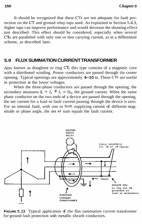
150 Chapter 5
It should be recognized that these CTs are not adequate for fault pro- tection on the CT and ground relay taps used. As explained in Section 5.4.3, higher taps can improve performance and would decrease the shunting effect just described. This effect should be considered, especially when several CTs are paralleled with only one or two carrying current, as in a differential scheme, as described later.
5.9 FLUX SUMMATION CURRENT TRANSFORMER
Also known as doughnut or ring Cr, this type consists of a magnetic core with a distributed winding. Power conductors are passed through the center opening. Typical openings are approximately 4-10 in. These CTs are useful in protection at the lower voltages.
When the three-phase conductors are passed through the opening, the secondary measures I, + Ih + I , = 3I,, the ground current. When the same phase conductor on the two ends of a device are passed through the opening, the net current for a load or fault current passing through the device is zero. For an internal fault, with one or both supplying current of different mag- nitude or phase angle, the net 01 sum equals the fault current.
GROUND FAULT RELAY
or nay not be g'ounded a t load Or elrewhere
CURRENT TrnNSFORMEII - -
FIGURE 5.13 Typical application of the flux summation current transformer for ground fault protection with metallic sheath conductors.

Relay Input Services 151
This is a flux summation, rather than individual summing of separate transformer secondary currents. The advantages are that the CT ratio is in- dependent of the load current or kVA of the circuit, and that it avoids the possible difficulties of unequal individual CT saturation or performance with paralleled CTs. The disadvantage is the limitation of the size of conductors that can be passed through the opening. A typical ratio for this Cr is 50:5, and the maximum opening is about 8 in. in diameter.
The CT is commonly used with a 0.2.-A instantaneous overcurrent unit. The combination provides a primary pickup of 5 A, rather than 2.5 A, if the exciting current were negligible. Specific applications are discussed in later chapters.
Metallic sheath or shielded cables passed through the toroidal CT can result in cancellation of the fault current. This is illustrated in Fig. 5.13. This applies either to three-phase cable, as shown, or to single-phase cables. The cancellation may be partial or complete, depending on the sheath grounding. This sheath component of fault current can he removed from passing through the CT by connecting a conductor, as shown.
5.10 CURRENT TRANSFORMER PERFORMANCE ON THE DC COMPONENT
Because transformers are paralyzed by direct current, CT performance is affected significantly by the dc component of the ac current. When a current change occurs in the primary ac system, one or more of the three-phase currents will have some dc offset, although none may be maximum and one could not have any offset. This dc results from the necessity to satisfy two conflicting requirements that may occur: (1) in a highly inductive network of power systems, the current wave must he near maximum when the voltage wave is at or near zero; and (2) the actual current at the time of change is that determined by the prior network conditions. For example, energizing a circuit with current being zero before closing the circuit at the instant when the voltage wave is zero presents a problem. By requirement 1 the current should be at or near maximum at this time. Thus, a countercurrent is pro- duced to provide the zero required by condition 2. This is the dc component equal and opposite the required ac current by condition 1, with the two adding to zero at the instant of closing the circuit.
After having provided this function, the dc is no longer required, hut it can disappear only by decaying according to the LIR time constant of the power system. This decaying dc acts somewhat like a low-frequency alter- nating current in passing through the current transformer. It can saturate the iron such that the secondary reproduction of the primary current can be

152 Chapter 5
severely limited and distorted. This is illustrated in Fig. 5.14 for a 20-times- rated fully offset current with resistive burden. This type of burden causes a sharp drop-off of the secondary current during each cycle.
After saturation occurs, the decay of the dc component results in the CT recovering, so that during each subsequent cycle, the secondary current more nearly approaches the primary. As the dc disappears, the secondary is again a reproduction of the primary. This assumes no ac saturation. It is possible, but rarely occurs, that the secondary current may be practically zero for a few cycles in very severe cases.
Inductance in the burden results in a more gradual drop-off, whereas a lower burden reduces the distortion. These several effects are shown in Fig. 5.14. As shown, this saturation does not occur instantly; hence, initially,
( 8 ) Per ""it Primary c u r r e n t
y1
t' Y 9)
L:
g o u
2 3 Y
4 Time
per U n i t Primary Current
W c LI
0 LI %. " Per u n i t SecOOdary c u r r e n t
j Time
FIGURE 5.14 Typical possible distortion in CT secondary current resulting from dc saturation: (a) large resistive burden; (b) smaller resistive burden. (Fig. 3 of IEEE 76-CHI 130-4, PWR Transient Response of Current Jrans- formers.)

Relay Input Services 153
the secondary current follows the primary current, before it is reduced and distorted by saturation.
The time to saturate and the calculation of the secondary current are complex and depend on many factors: the nature of the fault current, the constants and design of the current transformer, and the burden connected. A simplified method for estimating the performance of ring-core CTs is available from the IEEE report Transient Response of Current Transformers. From a practical standpoint and as a general ruie of thumb, the CTs used for relaying can be expected to reproduce, with reasonable accuracy, the primary current for about one-half cycle or more before significant dc saturation.
5.1 1 SUMMARY: CURRENT TRANSFORMER PERFORMANCE EVALUATION
Two types of current transformer saturation have been discussed:
5.1 1.1 Saturation on Symmetrical Ac Current Input Resulting from the CT Characteristics and the Secondary Load
Figure 5.15 shows typical secondary voltages as a function of the secondary burden. There is always an output although it may delay or be insufficient to operate relays. This saturation should be avoided, but this may not always be possible or practical.
Saturation on symmetrical ac is most critical at the point of relay decision. Thus, in differential protection, the decision point is at the current transformer nearest an external fault. A fault on one side of the current transformer is internal, for which the protection must operate, but the fault on the other side is external, and the protection must not operate. This external fault is often very large and requires good current transformer per- formance. Ac saturation should not occur for this protection.
For overcurrent protection of lines, the decision point is remote from the current transformer and generally not so critical because time is involved in relay operation; hence, some saturation can be tolerated. For heavy close- in faults, these relays may be operating on the relative flat part of their time curve, for which magnitude differences are not critical. This also applies to close-in heavy faults for instantaneous or distance-type relays.
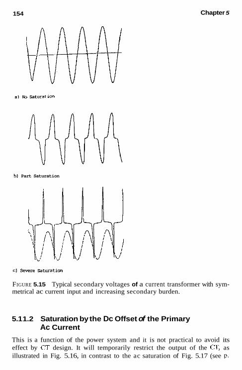
154 Chapter 5
a1 NO Satmation
b) Part Saturation
c) Severe Saturaticn
FIGURE 5.15 Typical secondary voltages of a current transformer with sym- metrical ac current input and increasing secondary burden.
5.1 1.2 Saturation by the Dc Offset of the Primary Ac Current
This is a function of the power system and it is not practical to avoid its effect by CT design. It will temporarily restrict the output of the Cr, as illustrated in Fig. 5.16, in contrast to the ac saturation of Fig. 5.17 (see p.

Relay Input Services 155
current
FIGURE 5.16 Typical hysteresis loops and residual flux in current trans- formers.
157). This can he critical in differential protection where several CTs are involved in the fault determination. Differential relay designs use various techniques to prevent misoperation, generally keyed to no ac saturation.
In most other applications dc saturation is not likely to be too severe, or to significantly inhibit the protection from a practical standpoint. How- ever, it should always be considered and checked.
Most faults tend to occur near maximum voltage, at which the prefault current is low in the inductive power system. This minimizes the dc offset; therefore, it is seldom at its maximum possible value. In many parts of the power system, the time constant will he short, such that when the dc offset occurs, it rapidly decays. Also, faults other than differential protection are not at the maximum value at the critical decision point of the protection.
For example, in line protection, the relay decision point is remote from the a s ; consequently, the fault current is often lower, and line resistance is available to help moderate the effect. Also, the decision point may not he

Chapter 5 156
too critical, for time is often involved to clear remote faults. Generally, the close-in high-current faults will be many times greater than the relay pickup current, and with high-speed relays, operation may take place before dc current transformer saturation occurs. Should saturation occur before the line protection relays can operate, generally a delay in operation occurs until the CTs recover sufficiently to permit operation. Thus, the tendency for this type of protection usually is to “underreach” momentarily, rather than “over- reach.”
5.12 CURRENTTRANSFORMER RESIDUAL FLUX AND SUBSIDENCE TRANSIENTS
When a current transformer is energized by a load for the first time, the excursion on the hysteresis loop is symmetrical, with a flux variation such as rr’ in Fig. 5.16. Faults with higher current produce increased flux and a wider excursion. When the fault is cleared and the primary current becomes zero, a unidirectional transient current can flow in the secondary. This is the trapped exciting current, which is out of phase with the fault primary- secondary current through the resistive-type burden before interruption. The time constant for this is usually short with resistive burdens, unless air gaps are employed in the CT core. This transient current may delay the dropout of very sensitive high-speed overcurrent relays used in breaker failure pro- tective schemes, and may cause misoperation for the short times pro- grammed in these schemes, particularly for HV system protection.
Interruption of the fault and the decay of I , to zero still leaves flux in the CT. This is called residual flux, such as at point s in Fig. 5.16. Now if the C T is reenergized with the original load current flowing, the flux ex- cursion would resume, but from the residual flux level s with a loop as ss’, where the flux variation of ss‘ = rr‘. However, it cannot continue in loop ss‘ because this would require direct current to maintain it in this offset position. So it shifts down to a symmetrical position tf’, at which the vari- ation tt‘ = ss’ = rr‘. During this shift a small direct current flows in the secondary circuit, according to the burden secondary time constant. Until the load changes or another fault occurs, the flux will vary in this ff’ loop indefinitely. If the circuit is opened to deenergize the primary current to zero, the residual flux would be the value existing at the moment of inter- ruption and somewhere within loop n‘. Thus, current transformers, once energized, will have residual flux anywhere between zero and the saturated value in either the positive or negative loop.
For a later fault, the residual can either add or reduce the CT capabil- ities. In the example, residual flux points s or t are much closer to the saturation level for flux excursions to the right, but are far away from sat-

Relay Input Services 157
uration for excursions to the left. Consequently, the performance depends on in which half-cycle the next fault occurs. Because this is not predictable in theory, the residual flux can cause saturation and problems in protection. However, the general experience in the United States has not indicated this to be a serious problem. Only a very few cases have been cited in which this might have caused problems.
Air-gap CTs have been used to minimize this residual; however, their performance for general application is not nearly as reliable. Although they do not saturate as rapidly as the nongap designs, their exciting current is much higher; there is a loss of steady-state accuracy and of transformation of the dc transient. The unidirectional CT current after a fault clears decays out much more slowly with air gaps and so is more likely to cause problems in breaker failure relaying, as outlined in the foregoing. Air-gap CTs still have minimal use in the United States.
5.13 AUXILIARY CURRENT TRANSFORMERS IN CT SECONDARY CIRCUITS
Auxiliary current transformers are sometimes required to provide (1) differ- ent ratios than would otherwise be available, ( 2 ) phase shift in the current, or (3) circuit isolation. They should be used to step down the current to the burden whenever possible, to minimize the impedance loading on the main current transformer. This is illustrated in Fig. 5.17. Z; is the impedance at the secondary of the main CT, which is the reflected impedance Z,, or load
PRIMARY
FIGURE 5.17 Auxiliary current transformers applied to change overall current transformer ratio.

I sa Chapter 5
connected to the auxiliary CT secondary. Neglecting the loss of the auxiliary CT yields
(5.6)
where N is the ratio of the auxiliary C E Thus, for a step-down connection with P S of 105, N = 2 and Zk = 0.25 Z,. However, with a step-up con- nection, where P S is 5:10, Z ; = 4.0 2,. With high lead resistance, an aux- iliary step-down CT near the main CT can be used to reduce this lead resistance load. The auxiliary CT does add its losses to the total load on the main CT.
5.14 VOLTAGE TRANSFORMERS FOR PROTECTIVE APPLICATIONS
Voltage transformers have wound primaries that are either connected directly to the power system (VTs) or across a section of a capacitor string connected between phase and ground (CCVTs). Typical units are illustratcd in Figs. 5.3 through 5.5, with connection schematics shown in Fig. 5.18.
Protective relays utilizing voltage are usually connected phase-to- phase, so the transformers are normally rated 120-V line-to-line. Taps may he provided to obtain either 69.3-V or 120-V line-to-neutral. When available, double secondaries provide the means of obtaining zero-sequence voltage for ground relays (see Fig. 5.18a). If only a single transformer secondary winding is available, an auxiliary wye ground-broken delta auxiliary voltage transformer can be connected to the secondary a, b, c bus of Fig. 5.18a for 3V,, similar to the connections shown. A typical example is shown i n Fig. 1.10. CCVTs commonly have double secondaries for both phase and 3V0 voltages (see Fig. 5.1%).
Three VTs or three CCVTs, such as shown in Fig. 5.18a and c, pass positive-, negative-, and zero-sequence voltage. The open-delta connection of Fig. 5.18b will pass both positive- and negative-sequence voltage, but not zero-sequence voltage.
VTs are used at all power system voltages and are usually connected to the bus. At about 115 kV, the CCVT type become applicable and generally more economical than VTs at the higher voltages. Usually, the CCVTs are connected to the line, rather than to the bus, because the coupling capacitor device may also be used as a means of coupling radio frequencies to the line for use in pilot relaying. This is discussed in Chapter 13.

Relay Input Services 159
(i) Primary (b) IC) - - . - - a
+ 3vrJ 4 FIGURE 5.18 Typical voltage sources for relays: The secondary circuits for the coupling capacitor voltage transformer (CCvr) device are simplified sche- matics, for concept only. (a) Secondary phase and ground voltage with three douhle secondary Vis connected phase-to-ground; (h) secondary phase volt- age with lwo single secondary Vis connected open delta; (c) secondary phase and ground voltage with three CCVTs connected phase-to-ground. [Only one phase shown, b and c phases duplicate with secondaries con- nected as in (a).]
Either type of transformer provides excellent reproduction of primary voltage, both transient and steady-state, for protection functions. Saturation is not a problem because power systems should not be operated above nor- mal voltage, and faults result in a collapse or reduction in voltage. Both have ample capacity and are highiy reliahle devices. VTs are normally in- stalled with primary fuses, which are no1 necessary with CCVTs. Fuses are also used in the secondary. A common practice is to use separate secondary fusing for voltage supply to different groups of relays used in the total protection. Fuses are a hazard. A loss of potential hy a fuse may result in unwanted, incorrect relay operations. In some cases, overcurrent fault de- tectors are used to minimize this possibility.
Some CCVTs may exhihit a suhsidence transient when the system voltage is suddenly reduced such that the secondary voltage momentarily is not a replica of the primary. This is caused by the trapped energy ringing in lhe secondary compensating or turning reactor (L) and the associated circuit. This transient can be at a differeut frequency from that of the system frequency, or unidirectional. This has not heen a problem for electrome- chanical relays, hut it may cause prohlems for solid-state types. Modern- design CCVTs are availahle to eliminate this problem.
160 Chapter 5
BIBLIOGRAPHY
See the Bibliography at the end of Chapter 1 for additional information.
ANSI/IEEE Standard (37.13.1, Guide for Field Testing of Relaying Current Trans- formers, IEEE Service Center.
ANSIAEEE Standard (37.13.2, Guide for Standard Conformance Test Procedures for Instrument Transformers, IEEE Service Center.
ANSI/IEEE Standard C57.13.3, Guide for the Grounding of Instrument Transformer Secondary Circuits and Cases, IEEE Service Center.
ANSVIEEE Standard C57.13.8, Requirements for Instrument Transformers, lEEE Service Center.
Connor, E. E., Wentz, E. C., and Allen, D. W., Methods for estimating transient performance of practical current transformers for relaying, IEEE Trans. Power Appar. Sysr., PAS 94, Jan. 1975, pp. 116-122.
Iwanusiw, 0. W., Remnant flux in current transformers, Ontario Hydro Res. Q., 1970, pp. 18-21.
Linders, J. R., Barnett, C. W. Chairman, Relay performance with low-ratio Ck and high fault currents, IEEE Trans. Ind. App/. 31:392-404 (1995).
Transient response of coupling capacitor voltage transformers, IEEE Power System Relaying Committee Report, IEEE Trans. Power Appar Sysr., PAS 100, Dec. 1981, pp. 4811-4814.
Transient response of current transformers, Power System Relaying Committee Re- port 76-CH1130-4 PWR, IEEE Special Publication. A summary report and dis- cussion, IEEE Trans. Power Appar Sysf. , PAS 96, Nov.-Dec. 1977, pp. 1809- 1814.
Wentz, E. C. and Allen, D. W., Help for the relay engineer in dealing with transient currents, IEEE Trans. Power Appar: Syst., PAS 101, Mar. 1982, pp. 517-525.

Protection Fundamentals and Basic Design Principles
6.1 INTRODUCTION
The best protection technique now and for more than 50 years is that known as differential protection. Here the electrical quantities entering and leaving the protected zone or area are compared by current transformers (Crs). If the net between all the various circuits is essentially zero, it is assumed that no fault or intolerable problem exists. However, if the net is not zero, an internal problem exists and the difference current can operate the associated relays. In general, internal faults provide significant operating current, even for fairly light faults.
Differential protection is universally applicable to all parts of the power system: generators, motors, buses, transformers, lines, capacitors, re- actors, and sometimes combinations of these. As the protection of each part of the power system is discussed, invariably, differential protection is the first consideration, and often it is the choice for the primary protection.
6.2 THE DIFFERENTIAL PRINCIPLE
This fundamental technique is illustrated in Fig. 6.1, and for simplicity, only two circuits to the protection zone are shown. Multiple circuits may exist, but the principle is the same. The sum of the current flowing in essentially
161

162
- 14
4 1 p - IP Protected Equipment ., m ..
~ or zone
c c L J ' W
L -
Chapter 6
(bl
IF1 Protected - IF2 v Equipment
L or zone c
- c I -1e-=1 " R F2 R
FIGURE 6.1 Basic current differential scheme illustrated for the protection of a zone with two circuits: (a) normal conditions, IOp = C' + I;; (b) internal fault I,, = I,, + Ir2 - (I; + 1:).
equals the sum of the currents flowing out during normal operation. The voltage differential system is similar and is discussed in Chapter 10.
For normal operation and all external faults (the through condition), the secondary current in Fig. 6.la in the protective relay is the difference in the exciting currents of the differentially connected current transformers. Per unit current distribution is shown. For example, I,, is the primary current in the lines entering or leaving the protected area. I,, ~ I , is the secondary ampere current and is equal to primary current divided by the current trans- former ratio minus the secondary exciting current. Even with exactly the same ratio and type of current transformer, the relay current Iop will be small,

Protection Fundamentals-Basic Design Principles 163
but never zero. This is because of the losses within the protected area and small differences between the same CTs. This assumes that no current trans- former significantly saturates for the maximum symmetrical ac through cur- rents. With different CTs and ratios, larger differences will exist that must be minimized or the pickup of the relay must be set not to operate on any through condition.
During external faults the transient performance of the several CTs resulting from the sudden increase in current and the associated offset (dc component) can produce rather large transient-operating currents. Thus, it is difficult and impractical to apply an instantaneous relay. Time-delay relays can be used with care.
For internal faults, Fig. 6.lb shows that the differential relay operating current essentially is the sum of the input currents feeding the fault. This is the total fault current on a secondary ampere basis. Except for very light internal faults, good discrimination is available to detect problems (faults) within the differential zone. For the differential relay to operate, it is not necessary for all the circuits to supply fault current if the circuits are not supplying current to the fault.
To provide high sensitivity to light internal faults with high security (high restraint) for external faults, most differential relays are of the per- centage differential type. Figure 6.2 is a simplified schematic of this type of relay for two circuits, as shown in Fig. 6.1. The secondaries of the (JTs are connected to restraint windings R . Currents in these inhibit operation. As- sociated with these restraint windings is the operating winding OP. Current in this winding tends to operate the relay. Differential relays may be of either fixed or variable percentage, and typical characteristics are illustrated in Fig. 6.3. The abscissa is the restraint current. This can be either the smaller current (Q or the larger current (I;), depending on the design. The ordinate is the current required to operate the relay. Fixed percentage relays exist between 10 and 50% and may or may not have taps to change the percentage.
'Lop+ Ii;; Ib' (y-; -1; -1; + or Zero
FIGURE 6.2 Percentage differential relay: (a) External faults; (b) internal faults.

164 Chapter 6
-- Variable -- Restraint
o,>erate -- 5 0 %
“OP)
current -- 408
2 5 8
i n 8
I
Restraint Current ( I R )
FIGUFIE~.~ Typical through current characteristics of various differential-type relays.
Thus with a 50% characteristic, an external or through current of 10 A would require a difference or operating current of 5 A or more for the relay to operate. With a 10% type, and 10 A through current, 1 A or more difference current would produce relay operation.
The variable percentage types do not have percentage taps. At low through currents the percentage is low because at these levels the current transformer performance is usually quite reliable. At high through-fault cur- rents, where the CT performance may not be as dependable, a high- percentage characteristic is provided. This gives increased sensitivity with higher security.
It is important to recognize that characteristics, such as those shown in Fig. 6.3, apply only for external faults or through current flow. Differential relays are quite sensitive to internal faults when the currents in the restraint windings are in opposite directions or one restraint current is zero, as in Fig. 6.2. These relays are calibrated with current through one restraint and the operating windings with no current through the other restraint(s). Typical pickup currents for differential relays are on the order of 0.14-3.0 A, de- pending on the type, tap, and application.
As has been seen, the differential principal compares the outputs of the current transformers in all the circuits into and out of the protected area or zone. For equipment, such as generators, buses, transformers, motors, and so on, the CTs usually are all in the same general area, so that it is not too difficult to interconnect their secondaries with the relays. For lines where the terminals and CTs are separated by considerable distances, it is not practically possible to use differential relays as described in the foregoing. Still the differential principle provides the best protection and is still widely

Protection Fundamentals-Basic Design Principles 165
used. This is true particularly at the higher voltages. A communication chan- nel, such as a pilot wire (wire or fiber-optic cable), power line carrier (radio frequency), audio tones over wire, or microwave is used for information comparison between the various terminals. These systems are discussed later.
6.3 OVERCURRENT-DISTANCE PROTECTION AND THE BASIC PROTECTION PROBLEM
Where differential is not utilized, overcurrent or distance relays are the major protection possibilities. Because faults produce an increase in the phase or ground, or both, currents in the system, overcurrent protection is widely applied at all voltage levels. Distance relays operating on the increase in current and decrease in voltage are used principally at the higher-voltage levels.
The minimum-operating criteria for overcurrent relays is shown in Fig. 6.4. These relays may operate instantaneous, with fixed or inverse time de- lays (see Fig. 6.7). The techniques for applying and setting these relays for the protection of equipment in the power system are covered in the later chapters.
2 Minimum Fault
Increasing Current 2x or more
R&y Pick-up
1 Maximum Load
i For Phase relays Max. short time load (asymmetrical offset, magnetizing inrush, cold load, unusual operation).
Max. zero Sequence unbalance, phase phase-to-ground (neutral) loads.
For Ground relays
'Nominally I for phase faults, 30 100 = 0.866130. or 310 for ground faults,
FIGURE 6.4 Criteria for selecting overcurrent relay taps.
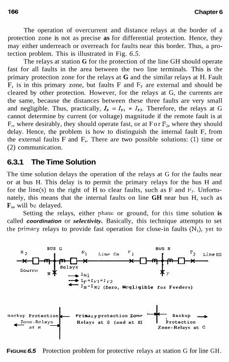
166 Chapter 6
The operation of overcurrent and distance relays at the border of a protection zone is not as precise as for differential protection. Hence, they may either underreach or overreach for faults near this border. Thus, a pro- tection problem. This is illustrated in Fig. 6.5.
The relays at station G for the protection of the line GH should operate fast for all faults in the area between the two line terminals. This is the primary protection zone for the relays at G and the similar relays at H. Fault F, is in this primary zone, but faults F and F, are external and should be cleared by other protection. However, for the relays at G, the currents are the same, because the distances between these three faults are very small and negligible. Thus, practically, IF = IF, = IF1. Therefore, the relays at G cannot determine by current (or voltage) magnitude if the remote fault is at F,, where desirably, they should operate fast, or at F o r FZ, where they should delay. Hence, the problem is how to distinguish the internal fault F, from the external faults F and F,. There are two possible solutions: (1) time or (2) communication.
6.3.1 The Time Solution
The time solution delays the operation of the relays at G for the faults near or at bus H. This delay is to permit the primary relays for the bus H and for the line(s) to the right of H to clear faults, such as F and FZ. Unfortu- nately, this means that the internal faults on line GH near bus H, such as F,, will be delayed.
Setting the relays, either phasc or ground, for this time solution is called coordination or selectivity. Basically, this technique attempts to set the primary relays to provide fast operation for close-in faults (N,), yet to
BUS G BUS H
+ I F = I F 1 = I r * - I N = I N 2 (Zero, Neqligible for Feeders)
Backup - + Protection Relays at G (and at HI - a t H Zone-Relays at G
Backup Protection primary protection zone
FIGURE 6.5 Protection problem for protective relays at station G for line GH.
Protection Fundamentals-Basic Design Principles 167
delay, for coordination with the relays at H, for faults at or near bus H. This is accomplished with inversed time-overcurrent relays, in which the oper- ating time increases as the current magnitude decreases, or with instanta- neous relays and constant (fixed) time delays. Coordination is discussed in more depth later, particularly when we discuss line protection in Chapter 12.
6.3.2 The Communication Solution .
The second, a communication solution is a type of differential protection, as outlined in the foregoing. The relays at H for the protection of line GH indicate by the direction of the power flow or the relative phase angle in- formation whether the fault is internal (F,) or external (F and F2). This information is communicated by a channel to the relays at G . Similarly, the relays at G provide information that is communicated to H. If the fault is in the primary zone (faults N, to Ft), both G and H operate together at high speed. For the external faults (on the bus at G or H, to the left of G, and to the right of H), the relays at both G and H do not operate. This is an elementary introduction to pilot relaying, which is expanded in later chapters.
6.4 BACKUP PROTECTION: REMOTE VERSUS LOCAL
The importance of backup and redundancy in system protection has been indicated in Chapter 1 and is discussed again in Chapters 8 through 13. Backup is defined as “protection that operates independently of specified components in the primary protective system.” It may duplicate the primary protection, or may be intended to operate only if the,primary protection fails or is temporarily out of service (IEEE 100). The various types can be illus- trated with reference to the protection at station G for the line GH of Fig. 6.5. Relays applied at G, as shown, are principally to provide primary pro- tection for line GH. For faults on the line, generally more than one of the several primary relays may operate. This provides primary backup through redundancy. For very important circuits or equipment, especially at HV and EHV levels, completely separate protection, operating from different CTs (and sometimes different Vrs), separate dc supplies, and operating different trip circuits on the breakers, is commonly used. One protective system is designated as the primary one, and the other as secondary-somewhat of a misnomer, for usually they operate together at high speed.
In the simple two-line system of Fig. 6.5, it was seen that the relays at G must be set to operate for the external faults F, F,, and others out on line HS to provide protection for fault F,. Thus, relays G provide primary

168 Chapter 6
protection for line GH, and backup protection for bus H and line HS. This is remote backup. If the F, F,, and so on, faults are not cleared by their primary relays and associated circuit breaker(s), relays at G should operate and remove the G source from the fault. Similarly, all other sources supply- ing current to the uncleared fault should be cleared by the backup operation of the relays at their remote terminals.
In recent years, it has been desirable to have the backup protection at the local station and to open all the breakers around the bus, rather than at the remote terminals. This is local backup, also associated with breaker failure. In this type of application, the breaker at H on line GH, rather than the breaker at G would be relayed to clear faults F., and so on, should the primary relays or the H breaker on line HS fail to operate.
For local backup there should be a separate, independent set of relays, as always exists for remote backup. This is available with the independent primary and secondary relay systems, indicated earlier, applied principally at high voltages. This independence may not exist in lower-voltage protec- tion systems.
If this independence is not provided there is the possibility that a fail- ure in the protection will prevent opening the local breakers to clear the fault. Clearing the fault under these circumstances could be achieved only by remote backup.
6.5 BASIC DESIGN PRINCIPLES
The design techniques used to provide relays for the protection of electric power systems bas progressed from electromechanical to solid state in a relative short period. The several steps in this progression were as follows:
1. Electromechanical: all analog measurements, comparisons, trip-
2. Solid state: Analog or operational amplifiers, solid-state operate
3. Hybrid: analog, with microprocessor logic, timing, and such,
4. Numerical: analog/digital and microprocessor, contact output
All types are in service, but the microprocessor designs are widely offered today. Many electromechanical relays are still providing good pro- tection around the world.
The basic protection characteristics are essentially the same for both electromechanical and solid-state relays. Thus, a review of these for the electromechanical relays provides a background for the modern units. Most of the basic characteristics were established some 60 years ago.
ping, and so forth
element, thyristor, or contact output
contact output

Protection Fundamentals- Basic Design Principles 169
6.5.1 Time-Overcurrent Relays
The time-overcurrent type relay, one of the first protective relays, developed some 60-70 years ago, is still widely used in many applications throughout the power system. Originally, it was basically a watthour meter with contacts and restricted disk travel. Today, as it has been for many years, the design is entirely different, except that it uses the fundamental induction disk prin- ciple. One typical type is illustrated in Fig. 6.6. Mternating current or volt- age applied to the main coil produces magnetic flux, most of which passes
Fixed Omtact
Muvible Contact
(a ) Top View Fixed Contact or stop
(b) Side View
FIGURE 6.6 Typical induction disk inverse-type-overcurrent or voltage relay: (a) Top view; (b) side view.

170 Chapter 6
through the air gap and disk to the magnetic keeper. This returns through the disk to the two side legs of the electromagnet. The shorted turns of the lag coil on one side leg cause a time and phase shift in the flux through that side of the disk to produce rotation of the disk. This rotation is damped by a permanent magnet. The spiral spring provides reset of the contacts after the operating quantity is removed or reduced below pickup value. Contacts attached to the disk shaft can normally he open or closed in the deenergized state. This combination produces fast operation at high current and slow operation at light current; hence, an inverse time characteristic. Over the years various shapes of time curves have evolved, which are shown in Fig. 6.7 for general comparison. Solid-state versions of these relays are available that essentially duplicate these curves and general characteristics, with lower burdens, wider application ranges, and adjustable time characteristics.
All relays have several taps, each of which represents the minimum current (or voltage) at which the unit will start to operate. This is the min- imum pickup value. Thus, a current relay set on tap 2 will begin to operate at 2.0 A, plus or minus the manufacturer’s tolerances. At this current, the time will be very long and difficult to check unless the current is maintained at an extremely accurate value. Any small or transient deviation at this level will result in a significant time change. Hence, manufacturers generally do
1.0
I n v e r s e Time . a
111 “2 very i n v e r s e
- 6 w Ijl
c .d
. 4 : .A f.
. 2
Minimum Time
0 0 5 10 15 20
Multiples of Tap (pick-up current1
FIGURE 6.7 Typical inverse-time-overcurrent relay characteristics. For gen- eral comparison, the curves are fixed at 0.2 s at 20 times minimum pickup current.

Protection Fundamentals-Basic Design Principles 171
not show their time curves below 1.5-2 times minimum pickup. Practically, this is not a usable part of the curve for protection.
The abscissa of the characteristic curves is shown in multiples of tap or pickup current. This is for the convenience of providing one scale for all taps. For example, with tap 5, a multiple of 5 on the curve represents 25 A, with tap 2, the multiple represents 10 A, and so on.
In addition to the taps, the spacing for the contact travel is adjustable and marked by a scale, known originally as a ‘‘time lever” and currently as a “time dial.” This provides different operating times at the same op- erating current level, a family of curves not illustrated in Fig. 6.7. Thus, for each relay type, typical time-current characteristic curves are available, usu- ally with curves from 1/2 through 11 time dial settings. These are available on semilog or on log-log fuse-type coordinate paper.
These relays have overtravel and reset times, which can be important in some applications. Overtravel in the electromechanical units is the travel of the contacts after the current drops below the pickup value. Typical values are on the order of 0.03-0.06 s, generally negligible in most applications. Reset time can be important in coordination with fast-reclosing or with fast- repetitive faults. It is a function of the time dial setting and the design. Data on reset are available from the manufacturers. The values are generally neg- ligible for solid-state types. Fast reset may or may not be advantageous when coordinating with fuses and relays that do not have fast-reset characteristics.
In a protective relay, the opening of the circuit breaker generally re- duces the current through the relay to zero. This may not be true when a relay is used as a fault detector and set to operate for faults well beyond the primary protection zone. Most induction disk time-overcurrent relays will not start to reset until the current drops below about 60% of the pickup current.
The relays described in the foregoing are nondirectional; that is, they can operate independently of the direction of the current. If this is not de- sired, a separate directional element, such as that discussed in Chapter 3, is used. The induction disk unit provides rotational torque by lag loops on the electromagnet to provide a flux shift. “Torque control” varieties have this lag circuit available for external use, or the directional unit contacts or output are internally connected in this circuit. As long as the lag coil or its equiv- alent is open, no amount of current will cause operation. When the direc- tional unit closes the circuit to the lag coil or equivalent, operation is as in the characteristic curves. This is directional torque control. The induction disk unit and its solid-state equivalent are used for overcurrent, overvoltage, undervoltage, combined over- and undervoltage, and power, as well as in other types of designs.

172 Chapter 6
6.5.2 Instantaneous Current-Voltage Relays Such relays are used in many areas of protection, such as overcurrent or over- or undervoltage units, to trip directly or as fault detectors for security. Typical types in general use are the clapper or telephone relay (Fig. 6 4 , solenoid or plunger relay (Fig. 6.9), and induction cup or induction cylinder relay (Fig. 6.10).
The term “telephone relay” dates from its very wide application in telephone exchange systems. Today, this use has been superseded by modern solid-state electronic switching. However, relays of this type are still used in many auxiliary applications, both ac and dc. It is a common output relay for many solid-state protective relays.
An example of the solenoid type as a dc type is its use as a seal-in contact switch (CS) of Fig. 1.9. With an ac coil and constructions, the solenoid unit serves as an instantaneous trip unit (IT and IIT).
The operation of the first two is basic; current or voltage applied to the coil produces flux, which attracts the armature or plunger. Contacts on the moving member are thus operated. Multiple contacts are possible, es- pecially on the telephone types.
The ac types have taps or other means to change the pickup value. For trip service, dropout is seldom a problem, and many of these units do not
s t a t i o n a r y
Moving Contact
I Hinge
c o n t a c t Schematic
FIGURE 6.8 Typical electromechanical clapper or telephone relay.

Protection Fundamentals-Basic Design Principles 173
contact Schematic
FIGURE 6.9 Typical electromechanical plunger relay.
Coils 2
I
Coils 1
or Cylinder
I Electromagnet
Top View
FIGURE 6.10 Typical electromechanical induction cup or cylinder relay,

174 Chapter 6
drop out after closing their contacts after operation until the current (voltage) drops to the order of 60% of the pickup value. Where this is a problem, high-dropout models of the Fig. 6.9 type are available. These will reset at 90% of the pickup value or higher. In general, fault detectors should be of the high-dropout type.
The ac induction cup or induction cylinder unit of Fig. 6.10 is basically a “two-phase motor,” with the two coils wound as shown on the four poles of the electromagnet. In the center is a magnetic core. Around or over this is the moving cup or cylinder, with the moving contacts and spring to pro- vide reset. When the fluxes of coils 1 and 2 are in phase, no rotational torque exits. As an instantaneous overcurrent unit, a phase shift is designed in one coil circuit, such that an operating torque is produced when the cur- rent is higher than the pickup value. The rotation is limited to a few milli- meters, enough to close the contacts. Typical times of operation are about 16-20 ms.
6.5.3 Directional-Sensing Power Relays
The induction cup and induction cylinder units are used to indicate the direction of power flow and magnitude. This first application for directional sensing was discussed in Chapter 3 . Typical characteristics are shown in Fig. 3.7. The operating current is passed through one set of windings and a reference voltage or current through the other. When the phase relations are as indicated, the unit operates. Because these units, as directional units, are very sensitive, they are used in almost all applications with fault-sensing units, such as the time-overcurrent or instantaneous overcurrent units dis- cussed earlier. Other types have tapped windings to operate when the power level exceeds a preset value.
6.5.4 Polar Unit
The polar unit i s a dc unit operating from ac quantities through a full wave- rectifier. It provides very sensitive, high-speed operation, with very low-level inputs.
As shown in Fig. 6.11, an electric coil is wound around a hinged annature with contacts in the center of a magnetic structure with nonmag- netic spacers in the rear. A permanent magnet bridges this structure to po- larize the two halves. Two adjustable magnetic shunts bridge the spacers to vary the magnetic flux paths.
With the coil deenergizcd and balanced air gaps (see Fig. 6.11a), the armature is not polarized, and contacts will float in the center. Now adjusting the gaps to provide unbalance, some of the flux is shunted through the
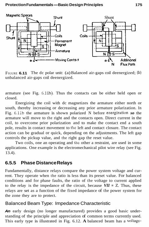
Protection Fundamentals-Basic Design Principles 175
Shunt
:t N FluxPoth
FIGURE 6.11 unbalanced air-gaps coil deenergized.
The dc polar unit: (a) Balanced air-gaps coil deenergized; (b)
armature (see Fig. 6.11b). Thus the contacts can be either held open or closed.
Energizing the coil with dc magnetizes the armature either north or south, thereby increasing or decreasing any prior armature polarization. In Fig. 6.11b the armature is shown polarized N before energization so the armature will move to the right and the contacts open. Direct current in the coil, to overcome prior polarization and to make the contact end a south pole, results in contact movement to the left and contact closure. The contact action can be gradual or quick, depending on the adjustments. The left gap controls the pickup value, and the right gap the reset value.
Two coils, one an operating and the other a restraint, are used in some applications. One example is the electromechanical pilot wire relay (see Fig. 13.4).
6.5.5 Phase Distance Relays
Fundamentally, distance relays compare the power system voltage and cur- rent. They operate when the ratio is less than its preset value. For balanced conditions and for phase faults, the ratio of the voltage to current applied to the relay is the impedance of the circuit, because VII = Z. Thus, these relays are set as a function of the fixed impedance of the power system for the zone they are to protect.
Balanced Beam Type: Impedance Characteristic
An early design (no longer manufactured) provides a good basic under- standing of the principle and appreciation of common terms currently used. This early type is illustrated in Fig. 6.12. A balanced beam has a voltage-

176 Chapter 6
I
A 1
E v contacts
Pivot
FIGURE 6.12 Distance relay-operating principles explained fundamentally by t h e balanced-beam impedance unit: (a) Distance relay to line GH; (b) simpli- fied explanation diagram with a beam unit.
energized electromagnet to restrain its movement and a current-operated electromagnet to close its contacts. By design and setting, the voltage- restraint force can he made to equal the current-operating force for a solid zero-voltage three-phase fault at the set point shown as nZ,,. This threshold point is known as the “balance point,” “operating threshold,” or “decision point” of the unit. For a fault between the relay and point n, the current I will be larger and V will decrease or remain approximately the same relative to the values for the fault at n. Thus, the increased current causes the beam to tip at the left end to close the contacts.
For an external fault to the right of point n, the current will he less than for the fault at n, and the voltage will be higher. Thus, the torque or pull of the voltage coil is greater than that of the current coil for restraint or no operation.
With the solid three-phase fault at the balance point n, the voltage at n will he zero. Then the voltage at the relay location will he the drop along the circuit, or InZ,~. Dividing this voltage by the current, the unit responds to impedance:

Protection Fundamentals-Basic Design Principles 177
Thus, the setting and operation are a function of the impedance from the relay voltage measurement point to the balance or 5et point.
Lewis and Tippett, in their classic paper (see Bibliography) showed that by using line-to-line voltages and line-to-line currents the reach of phase-type relays i s the same for three-phase, phase-to-phase, and lwo- phase-to-ground faults. Because the current cancels in Eq. (6.1), this reach is fixed for a given setting over a very wide range of fault currents, thereby providing a fixed reach, instantaneous protective relays not possible with an overcurrent instantaneous relay.
6.5.6 The R-X Diagram The characteristics of distance relays are shown most conveniently on an impedance R-X diagram, where the resistance R is the abscissa and the reactance X is the ordinate. Typical characteristics on these axes are shown in Fig. 6.13. For any given discussion the origin is the relay location, with the operating area generally in the first quadrant. Whenever the ratio of the system voltage and current falls within the circle shown, or in the cross- hatched area, the unit operates.
The elementary type discussed in Fig. 6.12 provided an impedance characteristic such as that shown in Fig. 6.13a. This obsolete design was independent of the phase relation of the voltage and current, thereby oper- ated in all four quadrants. Thus, a separate directional-sensing unit was nec- essary to prevent operation for faults in the system to the left of bus G (see Fig. 6.13a).
6.5.7 The MHO Characteristic The circle through the origin (see Fig. 6.13b) is known as an mho unit and is in wide use for line protection. It is directional and is more sensitive to fault currents lagging at about 60"-85" than to loads that are near a 0" to 30" lagging current. Load impedance is given by Eq. (6.2).
A high current is a low impedance. Thus, for heavy loads the impedance phasor moves toward the origin; for light loads, it moves away from the origin. In other words, distance relays of Fig. 6.13b through 6.13e can op- erate on a fault current less than the load current.

I 7a
lbl
Chapter 6
1-1 x 111 x Line to H line to H Line to H
R
FIGURE 6.13 dance; (b) mho; (c) offset mhos; (d) lens; (e) simple blinders; (0 reactance.
Distance relay characteristics on the R-X diagram: (a) Impe-
Lagging load from G to H (see Fig. 6.12a) is a phasor in the first quadrant as shown in Fig. 6.13b. Lagging load from H to G is a phasor in the second quadrant (- R + X ) on the R-X diagrams of Fig. 6.13.
A load of 5-A secondary and 120-V line to neutral appears to the relays as
120 ZIOdd = __ - - 13.86 secondary
fi(5) The equation of the mho circle through the origin is
(6.3)
The Z,J2 is the offset from the origin, Z, A is the radius from the offset point. When the offset is along theX axis and + is O", relative to the R axis, Z = 0. When + is 180", Z = Z,. When the mho circle is tilted, as in Fig. 6.13b, + is the angle of +B of the offset.

Protection Fundamentals-Basic Design Principles 179
Various operating points on the mho circle characteristic are deter- mined by Eq. 6.5;
zx = Z R C o S ( + H - +x) (6.5)
where Z, is the impedance from the origin to any point on the circle at angle c$~, and Z, is the relay reach at +,,.
For example, determine the reach of an rnho unit along a 75" angle line if the maximum load into the line is 5-A secondary at 30" lagging. From Eq. (6.3), the load impedance is 13.86-0 secondary. This is Z, in Eq. (6.5) with +x = 30". A typical angle for an mho unit is 75". Thus,
13.86 = Z, cos(75" - 30"), and solving yields
Z, = 19.60-fl secondary (6.6)
This can be translated into primary line ohms by the basic formula
(6.7)
where R, and R,, are the CT and VT ratios (see Chap. 5). The line reach on a 115-kV line with 6005 CTs would be
On the basis of the typical 0.8 Wmi, the 163.3-0 reach is about 204 m, a very long line at this voltage. Interestingly, one type of distance relay has a maximum specified reach at 20 secondary ohms, derived from Eq. (6.5).
The MVA represented by the 5-A load is
The primary protection of a line such as GH in Fig. 6.12 requires two distance units. This is shown in Fig. 6.14 for station G, using two mho units. Zone 1 unit operates instantaneously and is commonly set for nZ,, where n is less than 1, commonly 0.9. Zone 2 unit is set with n greater than 1 or about 21.5, depending on the system to the right of station H. A time- coordinating delay is required for zone 2 because it overreaches bus H.
A third zone, zone 3, is used in the hope of providing remote backup protection for the line(s) to the right on station H. This is often difficult, as explained in Chapter 12. Sometimes zone 3 at G is set to look backward from, or to the left of, station G . This can be used for backup or as a carrier- start unit in pilot relaying, as covered in Chapter 13. In these applications, the zone 3 mho-type unit, with offset to include the origin, should be used.

180
X
Chapter 6
Distance Protection
FIGURE 6.14 line GH of Fig. 6.12.
Distance mho units applied at G for the primary protection of
This characteristic is the lower mho unit in Fig. 6 .13~. This assures operation for close-in faults, for which the voltages are very low or zero.
The mho relays can be either single-phase or polyphase types.
6.5.8 Single-Phase MHO Units
For the single-phase types, three mho units (circles through the origin as in Fig. 6.13b) are required for a protective zone. All three units operate for three-phase faults, hut for phase-to-phase and double-phase-to-ground faults, only one unit operates. Thus,
TheA unit energized by IOb, and V., operates for ab and ab-gnd faults. The B unit energized by Ib,, and V,, operates for bc and bc-grrd faults. The C unit energized by I,,, and V,, operates for ca and ca-gnd faults.
The B and C units will not operate for the ab faults, the A and C units will not operate for the bc faults, and the A and B units will not operate for the ca faults.
This can be seen for the bc faults from Fig. 4.29d and 4.29e. The fault current I,, is large and the fault voltage V,, is small to provide a low im- pedance for operation. However, for the bc faults In& and I,. are small, whereas V,, and V, are large for a large apparent impedance. These impe- dances will he outside the operating circles for the A and C units. Similar conditions apply for the ab and ca faults.

Protection Fundamentals-Basic Design Principles
--)lab Air- gap Transformer
0"tP"tS t o Electromechanical cup U n i t or So l id S t a t e comparator
C T ' S I n p u t s and f r o m V T ' S :: ' F a - - v a b
FIGURE 6.15 Single-phase MHO unit (shown for the A unit)
The single-phase rnho unit is shown in Fig. 6.15. An air-gap trans- former, known as a transactor or compensator, provides a secondary voltage I,,Z, for the A unit, leading the primary current for less than 90". The di- ameter of the mho circle is determined by the mutual reactance of the trans- actor modified by the resistor. The combined output voltage is luJc - V",,. This voltage with a polarizing voltage Vah is compared to provide the mho circle through the origin as Fig. 6.13b and Eq. (6.4).
For electromechanical relays the induction cup unit of Fig. 6.10 is used where, for example, the A unit, lobZc (see Fig. 6.15) is on the left horizontal pole (operating coil), V,, on the right horizontal pole (restraining coil), and V,,, across the two vertical poles (polarizing coils).
For solid-state relays the two voltages are compared with a static-type phase-angle comparator (or the equivalent) digitized in microprocessor re- lays. The units may be packaged separately or in various combinations, depending on the manufacturer and application.
6.5.9 Polyphase MHO Units
The polyphase type has two units for a zone protection as shown in Fig. 6.13b; (1) an mho circle through the origin, operating for three-phase faults; and (2) a phase-to-phase unit, with a large operating circle partly shown as an arc. This unit does not operate on balanced conditions (load, swings, and such), nor for faults behind the relay (third and fourth quadrants).
Where distance relays are set to operate through wye-delta transform- ers the reach of the single-phase units for phase-to-phase faults is complex because a phase-to-phase fault on one side of the bank appears somewhat like a phase-to-ground fault on the other side. This is shown in Fig. 9.20.
Polyphase relays can be set through a wye-delta bank to operate for faults on the other side, using a setting that includes the X value of the transformer.

182 Chapter 6
Compensator Z c Electromechanical C y l i n d e r Unit or
I -31 --I - * a 0- b 'C Solid state Comparator
"an
~ a u l t beyond balance point smaller IaZp
v =van-l.51aZc F a u l t at(Zc) VCn Jr lavcn=+:::::y balance poinl
Vx=Van- Larger sazc Fault znside balance point
V x , V and vz Y Three-phase Faults
R ) Phasors for a T h r e e- p h a s e F a u l t (I, only shown lagging 90'1
FIGURE 6.16 The polyphase distance relay-three-phase unit: (a) Three- phase-fault unit; (b) phasors for a three-phase fault (/. only shown lagging 90").
Three-Phase Fault Units
The polyphase three-phase unit is shown in Fig. 6.16. Only one compensator is necessary to receive the phase a current. Thus, the output voltages are
v, = v,. - 1.S(Za - 3z,y,
v, = V*"
v, = V<"
(6.10)
(6.11)
(6.12)

Protection Fundamentals-Basic Design Principles 183
The cylinder unit (see Fig. 6.10) is like a two-phase motor operating when negative sequence uy is applied and restrains on positive sequence xyr or operates when V, lags V, and restrains when V, leads V,. A fault at the balance point (Z,) results in xyz in line as shown, a no-area-triangle and no operation. This is the decision point.
A fault on the line up to the balance point produces an xzy triangle and operation. A fault beyond the balance point produces an xyr triangle and no operation. For a fault behind the relay, the current reverses and a large xyr triangle results, again no operation. The memory circuit momen- tarily delays the collapse of v, and V, for closein faults that may reduce the phase b and c voltages to very low values, or zero.
In the compensator, 310 helps the unit operate on douhle-phase-to- ground faults when z, of the system is very low. From Fig. 4.15, it can be seen that as z, approaches zero, the double-phase-to-ground faults begin to look like a three-phase fault.
When the solid-state comparator is used V, = V,,, - (I. ~ I&?, and V,, = -jkV,, are compared.
Phase-to-Phase Fault Unit
The polyphase phase-to-phase unit is shown in Fig. 6.17 with two compen- sators. The equations are
(6.13)
(6.14)
(6.15)
With reference to Fig. 6.17, phase-to-phase faults at the balance or decision point VxVyV, provide a zero-area triangle for the electromechanical cylinder unit, or V, and V,? in phase for the solid-state comparator, with no operation. Any fault inside the triple-zone-negative sequence xzy, or when V, lags V,, causes operation. Any fault beyond or outside the trip-zone positive sequence xyz, or if V, leads V, results in no operation.
The phase-to-phase unit is a variable circle fixed at the balance point setting of Z, or Z, in Fig. 6.13b. The equation of this circle is
Offset .Z = +(zc - z,)
Radius Z = +(Zc + Z , ) k
(6.16)
(6.17)

Chapter 6
Electromechanical Cylinder unit or Solid State Comparator
Ia-Ib 4 -uALut+
Van vx Compensator Zc
V Y
'bn
IC
'b
Faults Inside Trip zone Faults Outside Trip Zone
FIGURE 6.17 The polyphase distance relay: phase-to-phase unit: (a) The phase-to-phase fault unit; (b) phasors for a bc fault (currents shown at 90").

Protection Fundamentals- Basic Design Principles 185
where Z,(Z,) is the set reach and Z, is the source impedance behind the unit. Although the circle extends into the third and fourth quadrants, this has no practical meaning because the fault current reverses for faults behind the unit. This reversal always provides xyz and V, leading V,, and no operation. Because the unit does not operate on positive sequence quantities (xyz), it will not operate on balanced conditions, such as load and swings.
This unit will operate for line-to-ground faults within approximately 30% of the Z, setting. This is not a fixed reach.
6.5.10 Other MHO Units
The mho unit can be offset, as illustrated in Fig. 6 .13~ or changed to other shapes, such as a lens, (see Fig. 6.13) tomato, rectangular, and so on. Each has its perceived advantages that are useful in various applications.
The characteristics of Fig. 6.13, but with the lower circle through the origin, and Fig. 6.13d and e are applicable to long, heavily loaded lines. Figure 6.13d is called a lens unit and Fig. 6.13e a single-blinder unit. These provide protection for faults along the line, but do not operate on heavy loads for which the load impedance would otherwise fall within the unit- operating circle.
Two reactance units (see next section and Fig. 6.13f) with their char- acteristics shifted, as shown in Fig. 6.13e, provide a restricted-operating zone along the protected line. The right unit operates for a large area to the left, the left unit for a large area to the right: outputs in series operation are indicated by the cross-hatched area. This type characteristic is generally used for out-of-step detection and tripping, as described in Chapter 14. If used for fault protection mho fault detectors must he used.
As indicated in Section 6.5.7, the mho unit of Fig. 6 . 1 3 ~ that includes the origin provides continued operation beyond any memory action for zero or near-zero-volt faults. An example is a bolted three-phase fault at or near the voltage transformer connection.
6.5.11 The Reactance Unit
The reactance unit can he obtained from the design of Fig. 6.15, with the air-gap transformer output of X instead of Z. The characteristic is a straight line at the set point (Z, or Z,) parallel to the R axis, as in Fig. 6.13f. It is not directional, but will operate for faults behind the relay. Thus, this unit is very “trigger happy” so operation must be restricted by an mho-type fault detector both for faults behind the relay and for load and swings.
The reactance unit appears to have increased fault arc protection he- cause arcs are resistive. This is true only for radial circuits in which fault

186 Chapter 6
current is supplied from only one terminal. When fault current is supplied from both terminals and the line is carrying load, the fault sources are not in phase. This results in the reactance units “seeing” the arc as an enlarged R + jX value. Thus, at one terminal the unit may not operate on arc faults, for they can appear outside the operating area and may cause reactance unit on the next section to incorrectly operate. This apparent impedance effect is discussed further in Chapter 12.
6.6 GROUND DISTANCE RELAYS In Chapter 4 it was shown that the positive sequence voltage drop during faults is maximum at the source and minimum or zero at the fault. Thus, the ratio of the voltage and current as in Eq. (6.1) indicated the distance to the fault. Unfortunately, for ground faults, the zero-sequence voltage drop is maximum at the fault and minimum or zero at the neutral or wye- grounded-delta power transformers. Thus, the ratio of the voltage and current
(6.18)
indicates distance behind the relay to the ground source, so cannot be used for ground distance relaying. Several methods have been used to resolve this; (a) voltage compensation or (2) current compensation.
Consider a phase-a-to-ground fault on a line with Z , , and Z,,, as the positive and zero sequence line impedances and n the location of the fault from the relay. The fault currents through the relay are I , , 12, I(,. Then for a fault at “z,,, with a single-phase unit
(6.19)
For (1) voltage compensation, subtract out nZ,,,(I, + 12) and use from Eq. 6.19, for the phase a-to-ground unit
Then
(6.20)
Additional units required for b-to-ground using V, for the c-to-ground
For (2 ) current compensation, let nZ, =pnZ,, wherep = Zo,/Z,,. Then faults using V,.
from Eq. 6.19
(6.21)
Protection Fundamentals-Basic Design Principles 187
If the current input is changed to I, + I2 + plo = I, + ( p - l)&, then
(6.22) V", z,, = = 4,.
I, + mIo
where m = 2, ~ Z,,JZ,,. Again additional units are required for b-ground and c-ground faults
except for the polyphase unit. Considering arc resistance and mutual coupling from an adjacent par-
allel line, the complete formula for current compensated single-phase ground distance relay is;
where
(6.23)
(6.24)
I,,, is the zero sequence current in the parallel line and Z,, the mutual coupling impedance between the two lines.
Another type operates on the principle that, at the fault V,, + V,, + V,, = 0. This relation is reproduced by compensators at the relay location. The modified V, is used as an operating quantity, and the modified V, + V2 as restraint. For single-phase-to-ground faults within the preset reach, V, operating is greater than the V, + V, restraint to trip. Faults outside the preset zone provide restraint greater than the operating quantity.
6.7 SOLID-STATE MICROPROCESSOR RELAYS
Solid-state units provide greater flexibility, more adjustable characteristics, increased range of settings, high accuracy, reduced size, and lower costs, along with many ancillary functions, such as control logic, event recording, fault location data, remote setting, self-monitoring and checking, and others.
In solid-state relays the analog power system quantities from current and voltage transformers or devices are passed through transformers to pro- vide electrical isolation and low-level secondary voltages.
The protection function outlined in the foregoing are available using microprocessor technology. The details of accomplishing this seem relatively unimportant to the protection principles; thus, they are beyond the scope of this book. However, typical logic units that may be involved in a micro- processor relay are shown in Fig. 6.18. In very general terns, these are (1) input transformers that reduce the power system current and voltage quan-

188
ac current
inputs and/or voltage and/or voltage
Filters
mplifier
Gain mpl i f l e r
Chapter 6
contact Relay mtputs Inputs 7.Micropme=r (Trip, close, i Alarm, etc.) Targets RAM ROM Tlm m e
Inpvt
FIGURE 6.18 Typical logic units in a microprocessor relay.
tities to low voltages and provide first-level filtering; (2) low-pass filter that removes high-frequency noise; (3) sample-hold amplifier that samples and holds the analog signals at time intervals determined by the sampling clock to preserve the phase information; (4) multiplexer that selects one sample- hold signal at a time for subsequent scaling and conversation to digital; (5) programmable gain amplifier for current signals that have a wide dynamic range (for voltage signals, the gain is 1; (6) Analog-to-digital converter that converts the analog signals to digital; (7) microprocessors with appropriate software, that provides the required protection characteristics that are am- plified to operate auxiliary units for tripping, closing, alarms, and so on.
6.8 SUMMARY
This chapter has presented the fundamentals of system protection and very briefly outlined various basic designs in wide use in these systems through- out the United States. The aim is to provide a background for the later chapters on the protection aspects of the various power system components.

Protection Fundamentals- Basic Design Principles 189
BIBLIOGRAPHY
See the Bibliography at the end of Chapter 1 for additional information
Lewis, W. A. and Tippett, L. S., Fundamental basis for distance relaying on a three phase system, AIEE Trans., 66, 1947, pp. 694-708. The original was presented, hut not published, at an N E E meeting in 1932.
Sonnemann, W. K., A study of directional elements for phase relays, AIEE Trans., 69, 11, 1950, pp. 1438-1451.
Van, C. and Warrington, A. C., Application of the OHM and MHO principle to protective relaying, AIEE Tram., 65, 1946, pp. 378-386, 490.

System-Grounding Principles
7.1 INTRODUCTION Power system grounding is very important, particularly because the large majority of faults involve grounding. Thus, it has a significant effect on the protection of all the components of the power system. The principal purposes of grounding are to minimize potential transient overvoltages; to comply with local, state, and national codes for personnel safety requirements; and to assist in the rapid detection and isolation of the trouble or fault areas.
A basic review of system grounding is in order, together with its fun- damental technology and a general evaluation of the methods. There are four types: (1) ungrounded, (2) high-impedance, (3) low-impedance, and (4) effective or solid grounding. Each has its application in practice, together with advantages and disadvantages. The recommendations are based on gen- eral practices plus some personal preferences. It should be recognized that there are many factors in each specific system or application that can well justify variations or a different approach. Just as relaying is highly influenced by personality, to a degree, so is system grounding.
7.2 UNGROUNDED SYSTEMS Ungrounded systems are power systems with no intentionally applied grounding. However, they are grounded by the natural capacitance of the
190

System-Grounding Principles 191
Id (bl
ag
ground i g l
icl (bl v =v vb”=v
C” cq
A
FIGURE 7.1 system: (a) normal balanced system; (b) phase a solidly grounded.
Voltage shin for a phase-a-to-ground fault on an ungrounded
system to ground. Thus, the fault current level is very low, such that equip- ment damage is minima; and it is not necessarily essential that the faulted area be rapidly isolated. This is an advantage; therefore, it is sometimes used in industrial plant systems where a high continuity of service is im- portant to minimize costly production process interruptions. However, un- grounded systems are subject to high, destructive transient overvoltages and, consequently, are always potential hazards to equipment and person- nel. Thus, they are generally not recommended, even though they are used.
Phase-to-ground faults on an ungrounded system essentially shift the normal balanced voltage triangle, as shown in Fig. 7.1. The small currents flowing through the series phase impedances will cause a very slight dis- tortion of the voltage triangle, but practically, it is as shown in Fig. 7.lb. A typical circuit is illustrated in Fig. 7.2 showing the current flow, and the sequence networks are shown in Fig. 7.3. The distributed capacitive re- actance valuesX,,, X,,, andX,,,. are very large, whereas the series reactance (or impedance) values X,,s, X,, X,,,, X,,., and so on, are relatively very small. Thus, practically, X,,. is shorted out by and X, in the positive-sequence network, and similarly for the negative-sequence network. Because these series impedances are very low, X , and X , approach zero, relative to the large value of Xoc. Therefore,

Z6 1

System-Grounding Principles 193
X1C,X2C,XQC are lumped equivalents of the distributed capacitance between phasee to network and to ground.
FIGURE 7.3 Sequence networks and interconnections for a phase-a-to- ground fault on a n ungrounded system.
and
3 v, XOC
I. = 31u =
This calculation can be made in per unit (pu) or amperes (A), remembering that V, and all the reactances (impedances) are line-to-neutral quantities.
The unfaulted phase b and c currents will be zero when determined from the sequence currents of Eq. (7.1). This is correct for the fault itself. However, throughout thc system the distributed capacitance X,, and X,, is actually paralleled with the series reactances X,,, X,, and so on, so that in the system I , and I2 are not quite equal to Io. Thus, I , and I , exist and are

194 Chapter 7
small, but they are necessary as the return paths for I, fault current. This is shown in Fig. 7.2. If I, = - 1 pu, then Ih = 0.577 /f30“ and I , = 0.577
In industrial applications where ungrounded systems might be used, the X,,, is equal practically to X,, = X,,. and is equivalent to the charging capacitance of the transformers, cables, motors, surge-suppression capaci- tors, local generators, and so on, in the ungrounded circuit area. Various reference sources provide tables and curves for typical charging capacitances per phase of the power system components. In an existing system the total capacitance can he determined by dividing the measured phase-charging current into the line-to-neutral voltage.
Note that as faults occur in different parts of the ungrounded system, X,, does not change significantly. Because the series impedances are quite small in comparison, the fault currents are the same practically and inde- pendently of the fault location. This makes it impractical for selective lo- cation of faults on these systems by the protective relays.
When a phase-to-ground fault does occur, the unfaulted phase-to- ground voltages are increased essentially by ~ (see Fig. 7.lb). Thus, these systems require line-to-line voltage insulation.
In the normal-balanced system (see Fig. 7.la), V ,,,, = V,,,,, V,,,, = V,,8, and V,,, = V,. When a ground fault occurs, the phase-to-neutral voltages and the phase-to-ground voltages are quite different. The neutral n or N is defined as “the point that has the same potential as the point of junction of a group (three for three-phase systems) of equal nonreactive resistances if connected at their free ends to the appropriate main terminals (phases of the power system)” (IEEE 100). This is the n shown in Fig. 7.lb.
/30“ pu.
From this figure, the voltage drop around the right-hand triangle is
v, - v,,. - v,,,* = 0
v, - If,, - v,,s = 0
v,.a + V“, = 0
v., + v, + v, = 3v0
V“. + Vb,, + v,, = 0
(7.3)
(7.4)
and around the left triangle,
Also,
(7.5) From the basic equations,
(7.6)
(7.7)
Subtracting Eq. (7.7) from Eq. (7.6), substituting Eqs. (7.3) through (7.5), and with V., = 0:

System-Grounding Principles 195
v,, ~ v",- + v,, - v,,. + v, - v, = 3V"
K, + V", + V", = 3V"
V,", = V" (7.8)
Thus the neutral shift is the zero-sequence voltage. In the balanced system of Fig. 7.la, n = g and V, is zero and there is no neutral shift.
7.3 TRANSIENT OVERVOLTAGES
Restriking arcs after current interruption in the breaker or in the fault can result in large destructive overvoltages in ungrounded systems. This phe- nomenon is illustrated in Fig. 7.4. In the capacitive system the current leads the voltage by nearly 90". When the current is interrupted or the arc extin- guished at or near its zero value, the voltage will be at or near its maximum value. With the breaker open this voltage remains on the capacitor to decay at the time constant of the capacitive system. In the source system, it con- tinues as shown for V , . Thus, in a half cycle, the voltage across the open contact is almost twice the normal peak value. If a restrike occurs (switch closed in Fig. 7.4), the essentially +1-pu voltage of the capacitive system will go to the system voltage of -1 pu. but because of the system inductance and inertia, it will overshoot to a maximum possibility of - 3 pu. If the arc goes out again near current zero (switch open) but restrikes (switch closed) again, the system voltage will try to go to +1 pu. but again will overshoot, this time to a potential maximum of +5 pu. This could continue to -7 pu. hut by this time the system insulation no doubt would break down, causing a major fault. Thus, ungrounded systems should be used with caution, and applied at the lower voltages (below 13.8 kV), where the system insulation levels are higher.
If used, prompt attention is important to locate and correct the ground fault. As the fault current is very low, it is easy to ignore the fault and continue operation. However, with the fault the other phases are operating at essentially 1.73 times normal line-to-ground voltage. If an insulation de- terioration caused the first ground fault, the higher voltages might accelerate breakdown of the unfaulted phases, to result in a double line-to-ground or three-phase fault. Then high fault currents would result, requiring fast shut- down and instant loss of production.
In actual practice there are no totally ungrounded systems. As soon as a fault detector is applied using one or three voltage transformers, the system is grounded through the high impedance of these devices. The resistance of the relays and associated ballast resistors helps limit the transient overvol- tages, so that very few cases of overvoltage actually exist.

196 Chapter 7
Breaker or i X l S + X T ,J
+ -7 vs
T X I C
T+5.0 I
Breaker contact opens Or arc C Y r r e n t is interrupted a*, or near *ex0
FIGURE 7.4 Transient overvoltage on an ungrounded system
7.4 GROUND-DETECTION METHODS FOR UNGROUNDED SYSTEMS
Voltage provides the best indication of a ground fault because the current is very low and, basically, does not change with the fault location. The two methods used are shown in Figs. 7.5 and 7.6. These indicate that a ground fault exists but not where it is in the primary system.
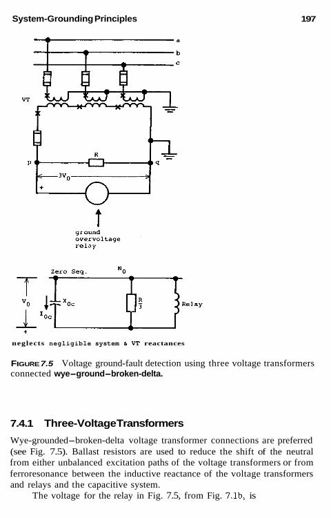
System-Grounding Principles
t
1 97
neglects negligible system 6 VT reactances
FIGURE 7.5 Voltage ground-fault detection using three voltage transformers connected wye-ground-broken-delta.
7.4.1 Three-Voltage Transformers
Wye-grounded-broken-delta voltage transformer connections are preferred (see Fig. 7.5). Ballast resistors are used to reduce the shift of the neutral from either unbalanced excitation paths of the voltage transformers or from ferroresonance between the inductive reactance of the voltage transformers and relays and the capacitive system.
The voltage for the relay in Fig. 7.5, from Fig. 7.lb, is

198 Chapter 7
a
FIGURE 7.6 Voltage ground detection using single voltage transformer.
v, = 3v, = v, + v, + v, = ( d V , , , cos 304 X 2 = 3VL,
(7.9)
Thus, the voltage available to the relay for a phase-to-ground fault on the ungrounded system is three times the line-to-neutral normal voltage. Usually, the VT ratio of primary V,.,:69.3 V is used so that the maximum solid ground relay voltage would be 3 X 69.3 = 208 V. Because the relay will be used to alarm, its continuous voltage rating should be greater than, or equal to, this 208-V value. Otherwise, an auxiliary stepdown voltage transformer must be used.
Figure 7.5 is simplified. Usually, the voltage transformer will be wye- grounded-wye-grounded and an auxiliary wye-grounded-broken-delta trans-

System-Grounding Principles 199
TAELE 7.1
Nominal system voltage (kv) VT ratio Ohms Wans at 208 V
Resistor R
2.4 2,400:120 250 175 4.16 4.200:120 125 350 7.2 7,200:120 85 51 0 13.8 14,400:l 20 85 510
former used. Sometimes the main voltage transformer will have a double secondary, one of which can be connected broken delta. Lamps can be con- nected across each broken-delta secondary winding to provide visual indi- cations. Typical resistance values across the secondary winding, derived from experience, are shown in Table 7.1.
7.4.2 Single-VoltageTransformer
The single-voltage transformer of Fig. 7.6 is especially subject to possible ferroresonance, without adequate resistance in the secondary. Without this resistance,
If the distributed system capacitance X , divided by the transformer exciting reactance X, equals 3, then theoretically, V, is infinite. Saturation of the voltage transformer would prevent this, but it is quite possible for the voltage triangle abc to have its ground point well outside this triangle. This is called “neutral inversion,” as illustrated in Fig. 7.7. Here the ratio of X J X , is 1.5, so in Eq. (7.10), V, = 2.0 pu as in Fig. 7.7. For simplicity, no resistance in the system nor across the voltage transformer secondary are assumed. Sus- tained phase-to-ground voltages almost four times higher have been expe- rienced. Also, the interaction of the variable transformer-exciting impedance with system capacitance can produce ferroresonance, with very high and distorted waveforms. This application of the single VT is not recommended, but if used the secondary system should be loaded with resistance.
This ground detection scheme must be used with caution to avoid “neutral” inversion and ferroresonance, as just outlined. The voltage relay is set to have its contacts held open for the normal line-to-ground secondary voltage. When a ground fault occurs on phase b, the voltage collapses and the voltage relay resets to close the undervoltage contacts. If a phase a or c

Chapter 7
FIGURE 7.7 Phasor diagram illustrating neutral inversion with unloaded volt- age transfotmer connected to phase b as shown in Fig. 7.6. Example with Xc = -j3 and X. = j2. All values in per unit.
ground fault occurs, the relay voltage increases by about 1.73 to cause the relay to operate on overvoltage. Either under- or overvoltage operation usu- ally operates an alarm to alert the operators of a ground fault so that they can arrange an orderly or convenient shutdown.
7.5 HIGH-IMPEDANCE-GROUNDING SYSTEMS
There are two types of high-impedance-grounding systems: resonant grounding and high-resistance grounding. The first has very limited use in the United States, although it is used elsewhere. The major American use is for generator grounding in the New England area. High-resistance grounding is widely used for generators and in industrial plants. These applications are reviewed later.
7.5.1 Resonant Grounding
These systems are also known as ground-fault neutralizer or “Petersen coil” systems. The total system capacitance to ground is canceled by an equal inductance connected in the neutral (Fig. 7.8). If the neutral reactor is tuned exactly to the total system capacitance, the current in the fault is zero. Ac- tually, in practice, taps on the reactor permit close tuning, so that the fault current is very small and the fault arc will not maintain itself. The circuit is a parallel resonance circuit, and the very low fault currents cause minimum fault damage. As the fault arc is extinguished, the reactor capacitance con- tinues to produce essentially a voltage equal to the system line-to-neutral

System-Grounding Principles 201
Fault
Resistance -03 --,I - 0 in System
FIGURE 7.8 Resonant grounding.
voltage; accordingly, the voltage across the arc is small, and the potential for restrike is negligible.
When this system is used on distribution systems, it becomes difficult to always provide a good match with system changes and switching. Fur- thermore, these systems are seldom transposed and may have many single- phase taps, all of which result in small zero-sequence voltages generated by the normal load currents. These voltages act in a series resonance circuit with the grounding reactor and shunt capacitance and may produce a high

202 Chapter 7
voltage across the reactor and capacitance. The system must have full line- to-line insulation. Experience has shown that a larger number of line-to-line faults may occur, and there can be a higher incidence of simultaneous faults. When used, a very sensitive overcurrent relay provides an alarm and, after some 10-20 s, if the fault still exists, the reactor is shorted out. This provides a high ground-fault current to operate in other relays to isolate the fault. It is not used in the United States, although there may he one or two older applications not yet converted to other-grounding methods.
The application of this technique to grounding unit generators is more favorable because of the short distances involved and the fixed value of system capacitance involved. With the very low fault current, it is promoted as permitting the continued operation of the generator with a ground fault until an orderly convenient shutdown can be arranged. After 45 years of experience on some 20 unit generators, several generator cable problems and one generator ground fault, 25% from the neutral, have been detected. In the last instance the generator remained on-line for 89 min with minimal copper and no iron damage. Still, there is a concern for the elevated voltages on the unfaulted phases should there be a solid ground fault at the terminals.
7.5.2 High-Resistance Grounding
In this system the power system is grounded through a resistor, and the accepted practice is to use a value of resistance equal or slightly less than the total system capacitance to ground. This provides a low fault current to minimize damage, yet limits the potential transient overvoltages to less than 2.5 times the normal crest value to ground. The fault current range normally encountered with this method is between 1- and 25-A primary, usually be- tween 1 and 10 A.
The grounding resistor may be connected in the neutral of a generator or power transformer (Fig. 7.9), or across the broken delta of line-to-ground- connected distribution transformers (Fig. 7.10). With the resistor in the neu- tral, as in Fig. 7.9, a solid ground fault can produce a maximum V, equiv- alent to the phase-to-neutral voltage as illustrated in Fig. 7.1. Thus a line-to-neutral-rated distribution transformer is normally used, although line- to-line ratings have also been used. For the grounding system of Fig. 7.10, a solid ground fault can raise the voltage on two of the distribution trans- formers to line-to-line equivalent (see Fig. 7.1). Thus, line-to-line ratings are suggested for this application, especially if the protection system is used for alarm, rather than direct trip.
The neutral connection (see Fig. 7.9) is used for unit generator appli- cations and in industrial systems with a single power transformer supply. For multiple generators connected to a common bus or for systems with

System-Grounding Principles 203
zero seqmnce
1 P. I . r r ' = Favlt
FIGURE 7.9 High-resistance grounding with resistor in t he neutral.
several power sources, the grounding system of Fig. 7.10 may be preferable. These two methods are best documented by typical examples.
7.5.3 Example: Typical High-Resistance Neutral Grounding
This type of grounding is applied to a 160-MVA 18-kV unit generator, as shown in Fig. 7.11. The area of ground protection is the generator to the low-voltage winding of the power transformer and to the high-voltage wind- ing of the unit auxiliary transformer. In this area the following capacitances to ground (microfarads per phase) must be considered:
Generator windings Generator surge capacitor Generator-to-transformer leads
0.24 0.25 0.004

Chapter 7
FIGURE 7.10 High-resistance grounding with resistor across distribution trans- former secondaries.
Power transformer low-voltage winding 0.03 Station service transformer high-voltage winding Voltage transformer windings 0.0005
Total capacitance to ground 0.5285
0.004 ~
= 5019.08Wphase (7.11) lo6 lo6
xc = - j 2.rfc = - j 2(3.1416)(60)(0.5285)
This capacitive reactance, in per unit on a 100-MVA 18-kV base, is from Eq. (2.15),
= 1549.1 pu lOO(5019)
1 8 2 (7.12)
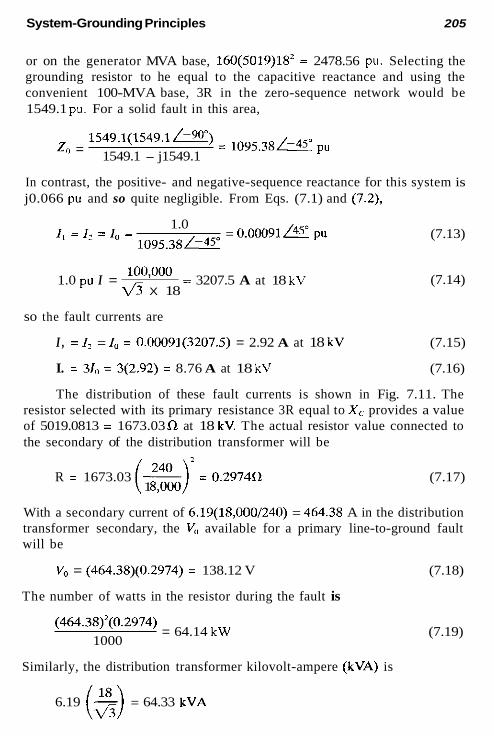
System-Grounding Principles 205
or on the generator MVA base, 160(5019)18* = 2478.56 pu. Selecting the grounding resistor to he equal to the capacitive reactance and using the convenient 100-MVA base, 3R in the zero-sequence network would be 1549.1 pu. For a solid fault in this area,
1549.1(1549.1@) = 1 0 9 5 , 3 8 ~ pu 1549.1 - j1549.1 z, =
In contrast, the positive- and negative-sequence reactance for this system is j0.066 pu and so quite negligible. From Eqs. (7.1) and (7.2),
= 0.00091 /45" pu 1.0
I , = I , = I - - 1095.38&
1.0 pu I = loo'ooo = 3207.5 A at 18 kV a X 18
(7.13)
(7.14)
so the fault currents are
I , = I? = I" = 0.00091(3207.5) = 2.92 A at 18 kV (7.15)
I. = 310 = 3(2.92) = 8.76 A at 18 kV (7.16)
The distribution of these fault currents is shown in Fig. 7.11. The resistor selected with its primary resistance 3R equal to X c provides a value of 5019.0813 = 1673.03 0 at 18 kV. The actual resistor value connected to the secondary of the distribution transformer will be
R = 1673.03 ~ = 0.2974fl i 1 :,:or (7.17)
With a secondary current of 6.19(18,000/240) = 464.38 A in the distribution transformer secondary, the V, available for a primary line-to-ground fault will be
V, = (464.38)(0.2974) = 138.12 V (7.18)
The number of watts in the resistor during the fault is
(464.38)2(0.2974) 1000
= 64.14 kW
Similarly, the distribution transformer kilovolt-ampere (kVA) is
(7.19)
6.19 - = 64.33 kVA ($3)

206 Chapter 7
(a )
FIGURE 7.1 1 Typical example of high-resistance grounding with neutral re- sistor: (a) unit generator system; (b) sequence networks, values in per unit a1 100 MVA, 18 kV; (c) fault current distribution.
equal within decimal-point accuracy. When this grounding is used for gen- erator units, tripping the unit is recommended, so these ratings can bc short- time, rather than continuous, ratings.
The normal charging current for this system would be
182000 = 2.07 Aiphase a1 18 kV I' = & X 5019
(7.20)
The use of a distribution transformer and a secondary resistor, rather than a resistor directly connected in the neutral, is an economic considera- tion. With high-resistance grounding it is generally less expensive to use the resistor in the secondary, as shown.
The flow of current through the system for a ground fault is sometimes hard to visualize from the zero-sequence quantities, such as shown in Fig. 7.11. Aithough positive- and negative-sequence impedances are quite neg- ligible in high-resistance grounded system, the three-sequence currents are equal at the fault [see Eq. (7.13)] and flow through lhe system. Since there is a positive-sequence source at either end of Fig. 7.11, the positive- and negative-sequence currents divide, as shown hy lhe 0.51 and 0.49 distrihu- tion factors in the positive- and negative-sequence networks. The approxi-

System-Grounding Principles 207
soritive ' "eqa l ive sequence
" (PO*. only, 6
. ?
( C )
FIGURE 7.11 Continued
mate currents flowing through this system are documented in Fig. 7.12. They are approximate, for the capacitance normally distributed is shown lumped. Before the fault a charging current of 2.07 A [see Eq. (7.20)] flows sym- metrically in the three phases. Because this is the same order of magnitude as the fault currents, Thevenin's theorem and superposition must be used to determine the currents flowing during the ground fault. Thus, in phase a from the generator to the lumped capacitance, I., is the sum of the prefault charging current plus the fault component, or 2.07/90" + 0.51 X 2.92/45" which is Ic1 = 3 .29 /71 , Similarly, I,, = 2.07- + 0.51 X 2.92- = 3.29/-48, and I , , = 2.07/210" + 0.51 X 2.92/165" = 3 . 2 9 / 1 9 1 .

208 Chapter 7
Distributed Capacitance Shown Lumped
FIGURE 7.12 Three-phase and sequence current distribution for the system of Fig. 7.1 1 during a solid phase-a-to-ground fault.
The negative- and zero-sequence components are as normally determined by the fault. In the lumped shunt capacitance, the charging current of 2.07 A cancels the zero-sequence phase a component of 2.07 A to give zero current, because this branch is essentially shorted out by the solid phase-a- to-ground fault. In the unfaulted phases the charging currents add to the zero-sequence component, providing currents as shown in Fig. 7.12. Figure 7.12 is similar and consistent with Fig. 7.2. The source voltage for Fig. 7.2 is 1/900, whereas for Fig. 7.12 it is lm.
Again, this assumes that none of the distributed capacitance is in the area to the right of the fault location. As has been indicated, the total fault value would not change for different fault locations; similarly, the distribu- tion will not change essentially, for no series impedance is considered be- tween the generator and the power transformer.
7.5.4 Example: Typical High-Resistance Grounding with Three Distribution Transformers
An industrial plant 13.8-kV system is illustrated in Fig. 7.13. The main source is the utility, but the plane has a small local generator. Either the

System-Grounding Principles 209
supply transformer or the generator could be grounded with a resistor in the neutral (if the supply transformer is wye secondary), but it is possible that either the local generator or the utility supply may be out of service. Thus, this system is to be grounded using the method shown in Fig. 7.10.
From estimating data or specific tests, we have the following capaci- tances to ground (microfarads per phase):
Source transformer 0.004 Local generator 0.11 Motor 0.06 Power center transformers 0.008 Total connecting cables 0.13 Surge capacitor 0.25
Total capacitance to ground 0.562 -
= 4719.9Wphase (7.21) 1 06 lo6 x, = - j ~ -
2mfC - -1 2(3.1416)(60)(0.0562)
Thus, the charging current of this 13.8-kV system is
13,800 I - = 1.69 Alphase at 13.8 kV
- lh X 4719.9 (7.22)
The total capacitance in per unit on a 20-MVA 13.8-kV base is from Eq. (2.15)
ZO(4719.9) 13.8'
x, = = 495.68 pu (7.23)
For high-resistance grounding (see Fig. 7.10), R = X,,,, so R in the zero- sequence network is 495.68 pu. For the system
= 350.5- pu (495.7)( -j495.7) z, = 495.7 - j495.7
(7.24)
For a line-to-ground fault the positive- and negative-sequence values of the system are very small and can be ignored. Thus, for a line-to-ground fault on this 13.8-kV system,
I , = I , = I - = 0.00285/45" pu - 350.5-
(7.25)

210 Chapter 7
ZOHVA Transformer
13.8kV Fault
rm Distribution Grounding Tiansformers - - Generator -
Load C e n t e r s
(a)
FIGURE 7.13 Typical example of high-resistance grounding with three distri- bution transformers: (a) industrial system; (b) zero-sequence network, values in per unit on 20 MVA. 13.8 kV; (c) ampere currents flowing for the ground fault.
The base per unit current is
L. = fi 20'ooo = 836.74 A at 13.8 kV X 13.8
(7.26)
Thus,
I , = I 2 = I , = 0.00285(836.74) = 2.39 A at 13.8 kV (7.27)
i. = 31, = 0.00856 pu = 7.16 A at 13.8 kV (7.28)
IoR = 0.00285 cos 45" = 0.00202 pu = 1.69 A at 13.8 kV (7.29)
The three distrihution transformers have the ratio 13.8 kV120 = 115. Thus, the secondary current for the ground fault i s
Imis.,) = 1.69(115) = 194.13 A (7.30)

212 Chapter 7
(V3VJ (V3 x 120)2 2mfC(V,,;,,,J2 = 377(0.562)(13.8)2
3R =
= 1.071.0 secondary 3V0 = 194.13(1.071) = 207.85-V secondary
The continuous resistor and transformer ratings are:
(194.13)2(1.071) = 40.36 kW loon Resistor: I’(3R) =
(7.32) (7.33)
(7.34)
(7.35)
The line-to-line voltage was used as during a fault; this voltage appears essentially across the primary winding. If relays are used to trip, short-time ratings may be used for the resistor and transformers.
7.6 SYSTEM GROUNDING FOR MINE OR OTHER HAZARDOUS-TYPE APPLICATIONS
A medium-high-resistance grounding system was developed originally for underground coal mining systems and is being used more and more for all mining and hazardous-type applications. In view of the great hazardous con- ditions often encountered in mining, these systems emphasize personnel safety and limit the fault current to 25-50 primary amperes. A typical sys- tem is shown in Fig. 7.14. All portable equipment in the mine is fed by a separate feeder that is resistance-grounded separately at a location at least 50 ft from the supply substation. Many applications limit the ground current to 25 primary amperes. This separate ground is carried as a fourth wire with its impedance not to exceed 4 a. A pilot conductor is also carried in the supply cable with a monitoring system to assure continuity of this ground. For a ground fault to frame at the portable equipment, 25 A flowing over the 4 4 safety ground wire would produce a maximum of 100 V across the operator. A very fast, sensitive relay is used to detect a ground fault and instantly trip off this feeder, without concern for fault location. With high-

E LZ

21 4 Chapter 7
hazard potentials, safety concerns override selectivity and continuity of ser- vice. All essential loads, such as lighting, fans, and vital support services, are fed from normal feeders from the substation.
7.7 LOW-IMPEDANCE GROUNDING
The low-impedance-grounding limits line-to-ground fault currents to ap- proximately 50- to 600-A primary. It is used to limit the fault current, yet permit selective protective relaying by magnitude differences in fault current by the power system impedances. There are also cost advantages because line-to-neutral equipment insulation can be used, for the unfaulted phase voltages are not increased significantly by the ground faults.
Most typically, this type of grounding is accomplished by a reactor or resistor in the system neutral (Fig. 7.15). In a distribution station it would be in the neutral of the delta-wye supply transformer. Several generator units that are connected to a common bus may be grounded in this manner. The zero-sequence network for this is also shown in Fig. 7.15.
When a delta-connected transformer exists, or a system-neutral is un- available, this type of grounding can be accomplished either by a shunt connection of a wye-grounded-delta or by a zigzag transformer. The wye- grounded-delta transformer could be applied only for grounding purposes and not for transmitting power. The grounding would be as just indicated and shown in Fig. 7.15.
I zero sequence
FIGURE 7.15 Low-impedance grounding with impedance in the system neutral.

System-Grounding Principles 21 5
FIGURE 7.16 transformer.
Low-impedance system grounding with a zigzag grounding
The zigzag transformer is illustrated in Fig. 7.16. Basically, this unit consists of three 1:l ratio transformers interconnected to pass zero-sequence current only. With the transformer polarities shown and because I,,, = I,, = Ic0 = I", zero-sequence current can flow, but positive- and negative-sequence currents cannot because I,, # lr, # I,,, and ls2 # lh2 # Ir2. The impedance of the zero-sequence path is the leakage impedance of the transformer A',. With a line-to-neutral voltage of 1 pu, the voltage across each winding is 0.866 pu. The zigzag transformer grounding is reactance, as the transformer resistance is very low. If the zigzag X, is too low for the desired fault limiting, a resistor (or reactor) can he added as shown.
7.7.1 Example: Typical Low-Resistance Neutral Reactor Grounding
The grounding reactor in the typical system of Fig. 7.17 is to be applied to limit the maximum line-to-ground fault current to 400-A primary. For con- venience a 20-MVA base is used for the calculations. From Eq. (A4.1-4):

216 Chapter 7
source 3 2 0 0 MVA 36 Short Circuit
2 0 HYA I 1 1 5 : 1 3 . 8 k V Q x=5.2%
D A V 1
Feeders
FIGURE 7.17 Typical example of low-impedance grounding.
= j0.00625 pu MVA,,, - MVA.,,. 3200
- Source: X, = X, =
Transformer: X, = j0.052 pu
Total X, = X, = j(0.0063 + 0.052) = j0.0583 pu
Total X,, = j(0.052 + 3X)pu
For a 400-A primary fault:
400 3
I , =i, = ia = - = 133.33 A at 13.8 kV
20’oo0 = 836.74 A ~ X 13.8 I,,, =
133.33 O - 836.74
1 , = 1 2 = 1 -__- - 0.159 pu
x, + x, + X, = j(0.1685 + 3X)
j1.0 j(0.1685 + 3X)
0.159 = .
(7.36)
(7.37)
(7.38)
(7.39)
(7.40)
(7.41)
(7.42)
(7.43)
(7.44)

System-Grounding Principles 217
X = 2.036 pu
(7.45) 13.S2(2.036)
20 - - = 19.38n at 13.8 kV (see Eq. 2.17)
7.7.2 Example: Typical Low-Resistance Neutral Resistance Grounding
The grounding resistor is to be applied in the typical system of Fig. 7.17 to limit the maximum line-to-ground fault current to 400-A primary. As for the previous example, X, = X, = j0.0583, but with a resistor,
Z, = 3R + j0.052 pu
Also, as before, 400 A for a line-to-ground fault represents an I, = I , = I , of 0.159 pu from Eq. (7.42). Thus
jl.0 3R + j0.1685
I , = I2 = I , = 0 . 1 5 9 p = (7.46)
This is best solved by the sum of the squares, so rearranging yields
jl.0 0 . 1 5 9 p
3R + j0.1685 =
(3R)’ + (0.1685)’ = (6.29)*
R = 2.09 pu = 13.8’(2.09) = 19.91 Cl at 13.8 kV (7.47) 20
Comparing the values of 19.38 [see Eq. (7.45)] for a reactor and 19.91 [see Eq. (7.47)] for a resistor shows that in many cases with resistor ground- ing, the angle can be ignored and the resistor added arithmetically, rather than vectorally. This simplifies the calculations, generally with little error. Thus, from a practical standpoint, where the resistor value is large compared with the system reactance or impedance, its value can be calculated directly as
(7.48)
7.8 SOLID (EFFECTIVE) GROUNDING
Effective grounding is defined by ANSIflEEE standards (IEEE 100) when the power system constants are

21 8 Chapter 7
(7.49)
where X , and Ro are the zero-sequence reactance and resistance and X , the positive-sequence reactance of the power system. Practically, this means that there can he no impedance between the system neutral and ground; hence, these systems are solidly grounded. Usually, this is accomplished by con- necting the neutral of the wye windings of the power transformer(s) to the station ground mat and ground. In the diagrams this would he shown as in Figs. 7.15 or 7.17, with X , R omitted. As a result the ground-fault currents can vary considerably, from very small currents to currents greater than the three-phase-fault value. The magnitudes depend on the power system con- figuration and constants, location of the fault, and the fault resistance, which may or may not he significant. Because the current level can vary with the fault location, it becomes easier to locate the fault and selectively isolate the trouble area by protective relays. The various techniques used are covered in the various chapters on equipment protection. The CTs shown in the grounded neutral in Figs. 7.15 through 7.17 are used to operate time-over- current relays set sensitively and with time to coordinate with the various line, feeder, and so on, relays that they “overreach.” Hence, this serves as backup-“last resort” protection for ground faults around the areas that are not properly cleared by their primary and associated backup protection.
7.8.1 Example: Solid Grounding
Assume that the transformer hank of the system of Fig. 7.17 is solidly grounded (X, R = 0). For a fault at F, X , = X , = j0.0583 pu [see Eq. (7.38)], and X , = j0.052 pu, all on a 20-MVA 13.8-kV base. Thus, X , + X , + X , = j0.1685 pu and
j1.0 I ,=I,=I - 5.934 pu ’ - j0.1685 = 4965.8 A at 13.8 kV (7.50)
I , = 310 = 17.8 pu
= 14,897.5-A fault current at 13.8 kV (7.51)
This is over 37 times larger than the 400-A low-impedance grounded example.
For a three-phase fault at F:
j l .0 I -__- - 17.17 pu ‘ - j.0583 (7.52) = 14,364.6 A at 13.8 kV
System-Grounding Principles 219
Thus, the ground-fault current is larger than the current for a three- phase fault. The difference in this example is small because the source is quite large compared with the supply transformer. If the source impedance were larger, the two fault currents would be lower, but the ground fault would be a larger percentage of the three-phase fault.
Figure 7.17 is a typical distribution transformer connected to a very large power system source. Thus, the source impedance is very low relative to the distribution transformer. For a three-phase fault on the bus
1 I -- per unit (7.53) '+ - x,
per unit where X, = X, 1 Im, = (Ur, + X") (7.54)
If the source impedance is neglected, then X , = X, = X, and
1 13* = I - - per unit
4n - x, If the source impedance is included, then X, and X, are greater than
X, and I+< is greater than IZ4, as in the foregoing example [see Eq. (7.51) and (7.52)].
If X,, is greater than X,, X, as will occur for faults out on the feeders, because line X , is generally about 3-3.5X,, then
Im, = is less than f3m
With the possibility of very low ground fault currents out on long rural or urban feeders that are difficult or impossible to isolate, solid grounding of the distribution transformers is recommended to provide as much ground fault current as possible for detection by the relays.
7.8.1 Ground Detection on Solid-Grounded Systems Fault current at any given location on solidly grounded systems will vary with fault location, such that overcurrent protection generally can be applied. This is in contrast with ungrounded and high-impedance grounded systems for which the current level does not vary significantly over the network.
Thus, zero-sequence voltage is used as a reference for ground direc- tional units and is obtained with wye-grounded-broken-delta voltage trans- formers in Fig. 7.5. For a solid phase-a-ground fault where V,, = 0, then from Eq. (7.9)
V,* = 3V0 = V,, + V, = 1 - 30" + 1 ~ 150" = - j l pu (7.55)
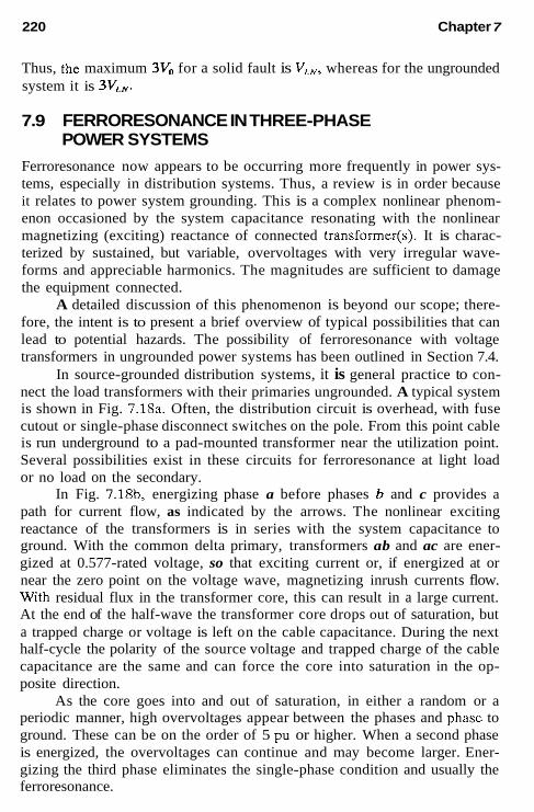
220 Chapter 7
Thus, the maximum 3V, for a solid fault is V,,, whereas for the ungrounded system it is 3V,,,.
7.9 FERRORESONANCE IN THREE-PHASE POWER SYSTEMS
Ferroresonance now appears to be occurring more frequently in power sys- tems, especially in distribution systems. Thus, a review is in order because it relates to power system grounding. This is a complex nonlinear phenom- enon occasioned by the system capacitance resonating with the nonlinear magnetizing (exciting) reactance of connected transformer(s). It is charac- terized by sustained, but variable, overvoltages with very irregular wave- forms and appreciable harmonics. The magnitudes are sufficient to damage the equipment connected.
A detailed discussion of this phenomenon is beyond our scope; there- fore, the intent is to present a brief overview of typical possibilities that can lead to potential hazards. The possibility of ferroresonance with voltage transformers in ungrounded power systems has been outlined in Section 7.4.
In source-grounded distribution systems, it is general practice to con- nect the load transformers with their primaries ungrounded. A typical system is shown in Fig. 7.18a. Often, the distribution circuit is overhead, with fuse cutout or single-phase disconnect switches on the pole. From this point cable is run underground to a pad-mounted transformer near the utilization point. Several possibilities exist in these circuits for ferroresonance at light load or no load on the secondary.
In Fig. 7.18b, energizing phase a before phases b and c provides a path for current flow, as indicated by the arrows. The nonlinear exciting reactance of the transformers is in series with the system capacitance to ground. With the common delta primary, transformers ab and ac are ener- gized at 0.577-rated voltage, so that exciting current or, if energized at or near the zero point on the voltage wave, magnetizing inrush currents flow. With residual flux in the transformer core, this can result in a large current. At the end of the half-wave the transformer core drops out of saturation, but a trapped charge or voltage is left on the cable capacitance. During the next half-cycle the polarity of the source voltage and trapped charge of the cable capacitance are the same and can force the core into saturation in the op- posite direction.
As the core goes into and out of saturation, in either a random or a periodic manner, high overvoltages appear between the phases and phase to ground. These can be on the order of 5 pu or higher. When a second phase is energized, the overvoltages can continue and may become larger. Ener- gizing the third phase eliminates the single-phase condition and usually the ferroresonance.

System-Grounding Principles 221
Similarly, the capacitance-to-ground and exciting reactances have the possibility of being in resonance for a broken fuse, broken conductor, and so on, where one phase is open as illustrated in Fig. 7.18~.
To limit the voltage on the open phase to about 1.25 pu or less,
(7.56)
where X, is the equivalent capacitive reactance per phase and X, is the equivalent exciting reactance. K has been indicated to be 40, although some feel it should be in the range of 5-10. In terms of the system, Eq. (7.56) can be expressed as
(7.57)
From this it can be observed that, in general, ferroresonance is more
1. With smaller-sized transformers. Ferroresonance can occur in small transformers in 25-kV and 35-kV systems, resulting from the internal capacitance of the transformer and the transformer exciting reactance. At higher voltages, of about 15 kV and above. With long cable runs or circuits with high capacitance.
For single-conductor cables with shields, typical capacitance values are about 0.25-0.75 (average 0.5) FF/mi, compared with open-wire line values of 0.01 p.F/mi. Thus, the capacitive reactance of underground cables is only about 2% of the capacitive reactance of an overhead circuit.
Whereas the probability of ferroresonance is low for systems operating at 15 kV or less, examples have been reported of ferroresonance in 15-kV systems with long cable runs. It is more probable in systems of 25 and 35 kV that are using cable. It is generally unlikely to occur if the primary windings are grounded-wye or grounded-tee, especially if the transformers are three, independent single-phase units or of the three-phase triplex type, where there is no magnetic coupling or negligible coupling between the phase windings, and with single-conductor shielded cable, where the inter- phase capacitances are very large. However, ferroresonance can occur with grounded-wye transformers, as shown in Fig. 7.19, either through the inter- phase capacitance on a long line or three-conductor cable or through un- grounded shunt capacitor banks.
It can also occur when four- and five-legged core transformer banks (Fig. 7.20) are used. There is magnetic and capacitive coupling betwe@ the three phases. This magnetic coupling between the phases with the phase-to-
likely to occur
2. 3.


System-Grounding Principles 223
OR IF PRIUARY IS UNGROUNDED + J W E . 4 I
( C )
FIGURE 7.18 Continued
ing closer or at the bank. Both of these can be expensive or impractical in many applications. Switching only with load can help, but again, may not always be practical and does not prevent the blown-fuse or broken-conductor problems that could occur at light load. The application of transformers with grounded primaries and minimum interpbase coupling generally should pro- vide a solution.
7.9.2 Ferroresonance at High Voltages
Ferroresonance is not limited to distribution, hut can occur almost anywhere in the power system. As an example, sustained 60- and 20-Hz ferroresonance

224 Chapter 7
V
"0 or very light load on Secondary
V
---* OPEN - t i t
Interphase Ungrounded Three 10 or Capacitance of Wye or delta 36 Triplex line or cable Capacitor Bank Tranlforrner
FIGURE 7.19 Ferroresonance possibilities with grounded transformers re- sulting from interphase capacitance on long circuits or with ungrounded shunt capacitor banks.
- Four-legged Core
h r
FIGURE 7.20 Three-phase transformer banks with four- and five-legged cores provide magnetic and capacitive coupling paths between the three phases that can contribute to ferroresonance.

System-Grounding Principles 225
FIGURE^.^^ capacitance and line reactors.
Ferroresonance on a deenergized 500-kV line between the line
has been experienced in a parallel 13-km 500-kV line where one end of each line connects without a breaker to separate 750-MVA grounded wye- delta tertiary autotransformer banks. This randomly occurred in the line when it was deenergized by opening the 500-kV breaker at one end and the autotransformer secondary 230-kV breaker at the other end with the parallel line still energized. The ferroresonance circuit is the 500-kV line capacitive reactance to ground and the exciting reactance of the 500-kV autotrans- former winding to ground. The mutual coupling between the two lines, which are on the same tower, provide the voltages for this phenomenon. The tertiary was essentially unloaded, so the solution to avoid future prob- lems was to load down the tertiary. Calculations indicated that about 590 kW was supplied to the ferroresonant circuit from the energized line and that about 250 kW additional by the 28-kV tertiary was sufficient to damp the oscillations.
Ferroresonance can occur between the line capacitance and line shunt reactors after a long line is deenergized. This is shown in Fig. 7.21 for a 500-kV line. Phase b has severe ferroresonance, whereas the other two phases “ring” as the trapped energy is dissipated.
Another case is shown in Fig. 7.22. This was ferroresonance that oc- curred between the voltage transformers inductance and breaker-grading ca-
F i ~ u ~ ~ 7 . 2 2 Ferroresonance on a deenergized section of a 345-kV ring bus between the voltage transformer inductances and the breaker-grading capacitors.

226 Chapter 7
pacitors when a section of a 345-kV ring bus was opened before the closing of line-sectionalizing switches to reconnect the line to the bus. Overvoltage on phase c lasted 15 min until the sectionalizing switches were closed. Some 4 months later this VT failed. Secondary resistance was added to the VT secondaries during switching operations to prevent this problem.
7.10 SAFETY GROUNDING
Power stations and substations for either utilities or industrial plants are built on ground mats. These are carefully designed to provide minimum voltage drops across the mat in all directions (step and touch potentials) and mini- mum impedance between the mat and tme earth or remote ground (ground potential rise). The primary aim is to reduce and minimize electric shock potentials for personnel safety. These designs are a specialized field and beyond our scope here. Standard IEEE 80 is the basic guide for this area.
All equipment frames within the ground-mat area in these stations must be solidly bonded to the mat. This includes all exposed metallic parts of relays, relay switchboards, fences, secondary wiring, and so on. Thus, all secondary circuits from the CTs and VTs are grounded. There should be only one ground in the circuit, and the general practice favors grounding at the switchboard or relay house. Multiple grounds may short-out relay(s) and prevent proper clearing of a fault, and may cause secondary wiring damage. A ground in the yard and another in the switchhouse put the secondary wiring in parallel with the ground mat, so that part of the heavy fault current can directly flow in the secondary winding to either damage or cause mis- operation. Only one ground in the circuit is sufficient to minimize any elec- trostatic potential.
If any equipment cannot be properly grounded, it should be carefully isolated from all contact with personnel. Special care must be taken for equipment associated with both the station and remote ground (transfer po- tential). Communication channels can fall into this category and are dis- cussed in greater detail in Chapter 13.
Electromagnetic induction should be minimized by design with the station. Two grounds are required to reduce this hazard; again, the technique is discussed in Chapter 13.
In areas involving electrical equipment where a ground mat is not possible or practical, safety must be carefully cxamined. The fundamentals of the problem are illustrated in Fig. 7.23. Although many diverse factors are involved, it appears that the average or reasonable resistance of a human being is from 1000 to 2000 Cl foot-to-foot and 500 to 1000 foot-to-arm, although these limits are general. R, can be made small by a low-impedance

System-Grounding Principles 227
Equipment Frame e
y - Ground
- - SAFB
W=
when 5- 0 6 R -_ when l$-m 6 R -0
-
FIGURE 7.23 Basic fundamentals of safety grounding.
ground wire (fourth wire or third wire in a single phase) that is effectively and adequately connected to ground with minimum impedance.
RM can be made large by high insulation to ground (nonwet) and by avoiding moist earth or possible contact with metallic surfaces, such as water pipes, that are connected to ground. Also sensitive and fast ground protection is helpful.
An application of this is in system grounding for mines (see Sec. 7.6, Fig. 7.14). In the home, the ground wire system has been used, but the modern approach is to make R,$ approach infinity through double insulation and other techniques, thus making ground faults more improbable.
7.11 GROUNDING SUMMARY AND RECOMMENDATIONS
A summary of the various grounding methods with suggested recommen- dations is given in Table 7.2. One column is for industrial and station service electrical systems for large generators in utility power systems. The other column is for all other parts of utility systems. As indicated, there are always many factors that influence the grounding choice, so any recommendations can be changed with very valid logic. Thus, the recommendations in Table

TABLE 7.2 Types of System Grounding and General Recommendations
Approximate Industrial and Utility transmission fault current utility station subtransmission
Types primary amperes service systems distribution General comments
Ungrounded Very low Not generally Not recommended recommended but used for high-SeNiCe continuity
High-resistance 1-10 Recommended for Not recommended high-service continuity
Low-impedance 50-600 Recommended" Not recommended
Effective-solid Low to very high Recommended" Recommended
1. Faults easy to detect but difficult
2. Fault current low, minimum
3. High potential of transient
4. Ferroresonance and neutral VT
5. Fault maintenance important 1. Same as above 2. Fault current low, low damage 3. Transient overvoltage limited to
2.5 VLN 1. Easier to detect and locate faults
selectively 1. Easy to detect and selectively
locate faults.
to selectively locate
damage
overvoltages
inversion possible
9 'Up to 1000 V, solid grounding; 1000 V-15 kV, low-impedance grounding; above 15 kV solid grounding. m P, 4 -l

System-Grounding Principles 229
7.2 are a guide. Although they reflect the personal opinions of the author, they also generally reflect actual practice in the United States.
For utility systems, only solid grounding is recommended. The logic here is that many distribution circuits extend through public areas and can he fairly long, with taps, branches, and so on. Thus, although the line-to- ground fault at the substation bus will he greater than the three-phase fault, this reverses quickly, as the high zero-sequence impedance soon becomes predominate. These lower fault currents for faults'out on the feeders, along with the probability of high earth-contact resistance at the lower voltages, often makes ground-fault detection very difficult if not impossible. These currents are quite hazardous because of the involvement or presence of the public. Any fault-limiting by neutral impedance tends to increase signifi- cantly the difficulty of detecting light faults out on the feeders.
For very short-line distribution circuits, fault-limiting may be desirable and is generally recommended for industrial systems from 1000 V to 15 kV. Here the distances between supply and utilization are usually quite short and are over or in an area not accessible to the public. Because most faults involve ground, it is desirable to limit their current magnitude and possible damage, which can be high because of the short distances of the utilization equipment from the supply source.
Solid grounding is used in most applications at utilization voltages lower than 1000 V. Frequently, this is required by local, state, or national codes. Above 15 kV, the general practice is solid grounding.
BIBLIOGRAPHY
See the Bibliography at the end of Chapter 1 for additional information.
Cottrell, R. G. and W. D. Niebahn, An analysis of potential ferroresonance at 138 kV distribution substations, McCraw-Edison's The Line, 8012 pp. 9-12, 17-18.
Forster, R. S. and L. R Beard, Solving the feerroresonance problem, Transmission Disiribucion, Dec. 1984, pp. 44, 46, 48.
Gleason, L. L., Neutral inversion of a single potential transformer connected to ground on an isolated delta system,AIEE Trans., 70, P. 1, 1951, pp. 103-111.
Hopkinson, R. H., Ferroresonant overvoltage control based on TNA tests on three- phase delta-wye transformer banks, IEEE Trans., PAS-86, No. 10, Oct. 1967, pp. 1258-1265.
Hopkinson, R. H., Ferroresonant overvoltage control based on TNA tests on three- phase wye-delta transformer banks, IEEE Trans., PAS-87, No. 2, Feb. 1965, pp. 352-361.
IEEE Green Book, Standard 142-1982, Recommended Practice for Grounding of Industrial and Commercial Power Systems, IEEE Service Center.
IEEE Standard 80, Guide for Safety in AC Substation Grounding, IEEE Service Center.

230 Chapter 7
Locke, P., Check your ferroresonance concepts at 34 kV, Transmission Distribution, Apr. 1978, pp. 32-34, 39.
Price, E. D., Voltage transformer ferroresonance in transmission substations, Texas A&M University 30th Annual Protection Relay Engineers Conference, April 25-27, 1977.
Rudenberg, R., Transient Performance of Electric Power Systems. MIT Press, Cam- bridge, MA, 1969.
Smith, D. R., S. R. Swaneon, and J. D. Bout, Overvoltages with remotely-switched cable fed grounded wye-wye transformer. IEEE Trans., PAS-75, Sept.-Oct. 1975, pp. 1843-1853.

Generator Protection: Utility and Nonutility Owned
8.1 INTRODUCTION AND POTENTIAL PROBLEMS
Utility, industrial, and independent power producer (IPP) generation is sub- ject to several potential hazards for which protection should be considered and given careful attention. These problems can be categorized as
1. 2.
Internal faults within the generator unit protection zone Abnormal operating or abnormal external system conditions, in- cluding external faults not cleared
The protection discussed herein begins with the ac source and is pri- marily for synchronous or induction generators and their connections to the ac power system. This protection is relatively independent of the primary power source.
We review the application of various protective relays to the generators and related areas. An important and vital part of these units is the regulating and control systems. These have their own protection, limiters, and safety features. Also, in recent years sophisticated monitoring and on-line diag- nostic systems have become available to monitor the temperatures in various parts of the units, to detect arcs by radio frequency and other methods, to sample the gas or water coolants for pollution, and to provide trends in abnormal situations for early warning of possible problems. A discussion of
231

232 Chapter 8
these is beyond the scope of this book. In many instances, they add impor- tant additions, backup, or supplements to the protection discussed here.
8.1 .I Utility Generators
Utility generators are synchronous machines generally above 20 MVA, and located in stations as near or convenient to the prime-mover supply or major utilization areas as possible. Typical hydrodriven generators are shown in Fig. 8.1. These have vcrtical shafts. Other prime-mover generators generally have horizontal shafts.
8.1.2 industrial Generators
Industrial generators often use excess by-products to provide plant power and, thus, are not usually large units. Generally, they arc synchronous ma- chines interconnected to the utility to receive additional or emergency power. They may supply excess power to the utility. For utility system interruptions
FIGURE 8.1 Four 100-MVA, 13.8-kV vertical-shaft hydrogenerators. The hy- draulic turbines (not shown) are located on the floor below. (Courtesy of S e - attle City Light.)

Generator Protection 233
they must be disconnected and resynchronized to the utility when service is restored. They also can be classed as IPP, CO-Gen, and such.
8.1.3 Independent Power Producer Units
Electric power sources connected to, but not owned by, a utility are desig- nated very generally as independent power producer (IPP) units or nonutility generation (NUG). These are primarily for the sale of electric power to utilities.
More specific are customer owned generator (Co-Gen) and dispersed storage and generation (DSG). Generally, Co-Gen are steam units and DSG are power from renewable sources such as wind, solar, hydro, biomass, urban waste, or other.
Co-Gens and DSGs can vary in size and may be connected at any voltage level of the utility. DSG installations generally are smaller, but have the potential to increase in size as they become more profitable with tech- nology advances and efficiency. They are often connected either single-phase or three-phase to the utility distribution system.
The ac connections to the utility are classified as line-dependent or line-independent.
Line-dependent DSGs include induction generators and line- ommutated inverters that need an external sonrce of reactive power for excitation. Normally, this would come from the connected power system so would not be available when the interconnection is opened. However, if the interruption leaves the DSG islanded with other equipment able to supply reactive power, they may continue to operate. With this possibility these DSGs must be disconnected by under- or overfrequency (81) and under- (27) or overvoltage (59) relays (see Fig. 8.3). A transfer trip from the utility may be required.
Line-independent DSGs include synchronous generators and self-com- mutated inverters. These continue to supply power to the system problems and must be disconnected and eventually resynchronized.
The reasons IPP and industrial generation must be promptly discon- nected from the utility system whenever the utility has an interruption in- volving or affecting the interconnection are (1) to avoid the NUG or IPP source from continuing to supply the fault, (2) damage to the NUG or IPP source when the utility restores the interconnection (connecting sources out of synchronism), (3) personnel hazard to the utility employees (and public) who may contact equipment not completely deenergized, (4) potential dam- age to other customer’s equipment or to the NUG or IPP unit by high or low voltages, ferroresonance, high or low frequencies when the NUG or IPP and loads are left islanded together, and (5) to maintain high-quality service to customers.

234 Chapter 8
There is a wide variety of these sources and their interconnections to the utility. Each utility has its own technical requirements for these inter- connections based on its safety practices, operating procedures, and design practices. These are to ensure a high quality of service and of safety for personnel (utility, NUG or IPP, customers, general public), and protection for all the equipment. Thus, close cooperation is very important between everyone involved in planning, design, construction, and operation of the interconnection.
The hazards and problems considered are as follows:
A. Internal faults 1.
2.
1. 2. 3. 4. 5. Overload (49) 6. 7. Under- or overfrequency (81) 8. 9.
Primary and backup phase or ground faults in the stator and associated areas Ground faults in the rotor and loss of field excitation
Loss of prime-mover; generator motoring (32) Overvoltage: volts or hertz protection (24) Inadvertent energization: nonsynchronized connection (67) Unbalanced currents: breaker pole flashover (61)
Off-frequency operation for large steam turbines
Undervoltage (27) and overvoltage (59) Loss of synchronism: out of step
B. System disturbances and operational hazards
10. Subsynchronous oscillations
8.2 GENERATOR CONNECTIONS AND TYPICAL PROTECTION
The common connections for generators are as follows: 1. Direct connected (one or several) each through a circuit breaker to
a common bus, as illustrated in Fig. 8.2: Usually they are wye-grounded through impedance, but may be undergrounded, or are delta-connected. They may be connected to a grounded power system or to the power system through a delta-connected transformer.
Typical protection for these utility, industrial, or IPP generators is shown in Fig. 8.3. For industrial and IPP generators under- and overvoltage and under- and overfrequency relays are mandatory toward disconnecting the power sources from the utility. A separate transfer trip channel from the utility to the IPP unit may be required to assure that the IPP unit is not connected when the utility recloses to restore service. This is important

Generator Protection
m
m
235
,,
1. T3 system
FIGURE 8.2 Direct-connected generator units (one or more) to a common system bus.
where the IPP and industrial generation may be islanded and able to supply the utility loads in the island.
2. Unir connected, in which the generator is connected directly to an associated power transformer without a circuit breaker between, as shown in Fig. 8.4. This is the common connection for the large generators in util-
system
FIGURE 8.3 Typical protection for a direct-connected generator. (*) Dotted re- lays are optional except 29/57 under- or overvoltage and 81 under- or over- voltage mandatory for nonutility generators connected to a utility; (#50) not always applicable.

236 Chapter 8
Transformer
TO System
P unit Auxiliaries
F~GURE 8.4 Unit-connected generator.
5 0 / 5 1
or Alternate Resonant Grounding
"nit service nu. Subharmonic rn,ection
FIGURE 8.5 Typical protection for a unit generator and for large generators in utility systems.

Generator Protection 237
ities. Most generators are wye-connected, with a few connected delta. These can he a single generator or two separate generators (cross-compound) that are supplied by a common prime-mover system. Cross-compound generators may have the separate units directly connected together to a single trans- former, or connected to separate secondary delta windings of a three-winding power transformer. Generators are also connected to the power system through autotransformers.
Typical protection €or the unit-connected generator is shown in Fig. 8.5. The function and protection of the various units are described in the following sections.
The individual protection units shown in Figs. 8.3 and 8.5 may be separate relays or may he combined in various combinations. The multi- function digital (microprocessor) relays provide many functions in a single package along with digital fault recording, self-checking, and so on.
8.3 STATOR PHASE-FAULT PROTECTION FOR ALL SIZE GENERATORS
Phase faults seldom occur, but when they do, large fault currents can flow. As indicated in Chapter 6 the best protection is differential (87), conse- quently, this type is recommended for all generators, except possibly for small units of 1 MVA and less. This provides sensitive protection for phase faults, but may not provide ground fault protection, depending on the type of grounding used, as covered in Chapter 7. The fundamentals of differential protection are outlined in Chapter 6 .
8.3.1 Differential Protection (87) for Small kVA (MVA) Generators
The preferred method for small units is shown in Fig. 8.6. The limitation is the ability to pass the two conductors through the window or opening of the CT. Typical opening diameters are about 4-8 in. However, where this is possible, high-sensitivity, high-speed protection is obtained, and CT perfor- mance does not have to be matched, for there is only one involved per phase. The flux summation CT ratio (commonly 50:5) is independent of generator load current. Typical sensitivities on the order of 5-A primary current can be obtained. This provides protection for both phase- and ground-fault cur- rents as long as the fault level for faults within the differential zone is greater than the sensitivity.
This scheme does not provide protection for the connections from the flux summation CT to the generator breaker unless the CT is on the bus

238
Generator
I I A
Chapter 8
b
c
I AS Desired
* S O For the 87G Function
FIGURE 8.6 Differential protection for small generator units with flux sum- mation current transformers and a n instantaneous overcurrent (50) relay.
side of the breaker and the generator neutral side leads are carried to that point. This is seldom practical, so other protection must be provided for this area between the flux summation CT and the breaker. In general, this scheme (see Fig. 8.6) is more sensitive as long as the generator CT ratio is greater than 1505 to 200:5. If the flux summation CT is not applicable and differ- ential protection is desired, the scheme of Fig. 8.7 can be used.
8.3.2 Multi-CT Differential Protection (87) for All Size Generators
The basic principles of this protection were covered in'section 6.2. It is widely used to provide fast and very sensitive protection for the generator and associated circuits. The 87 relays are connected to two sets of current transformers; one set in the neutral leads, the other in the line side. For generators with associated breakers, the line-side CTs are usually associated with the breaker, as shown in Figs. 8.2 and 8.3.
For unit generators the line-side CTs are usually quite close to the generator, basically at the generator terminals. Typical connections for the three-phase units are shown in Fig. 8.7 for both wye- and delta-connected generators.
If current transformers are available at each end of the windings for the delta-connected generators of Fig. 8.7b, differential relays can be applied for winding protection. The connections would be similar to those shown in Fig. 8.7a. However, this would not provide protection for the junction points or the phase circuits that are within the protective zone (see Fig. 8.7b).

Generator Protection
Generator
a
b
c
239
(b)
FIGURE 8.7 Typical differential (87) connections for the protection of wye- and delta-connected generators: (a) wye-connected generator; (b) delta- connected generator.

240 Chapter 8
Usually, the differential CTs have the same ratio, and preferably they should be of the same type and manufacture, to minimize mismatch errors for external faults. This is possible for the unit generators of Figs. 8.4 and 8.5, but difficult for those of Figs. 8.2 and 8.3 where the CIS in the neutral are one type and those associated with the breaker are another type. It is preferable not to connect any other equipment in the differential circuit and to keep the lead burden as low as possible. Generally, the impedance of the restraint winding of differential relays is low. All this contributes to a total low burden and increased performance margins for the CTs.
The application recommendations permit the use of sensitive generator differential relays with low percentage characteristics, typically 10-25% for the fixed percentage types and the equivalent or lower for the variable types.
Relay sensitivities (pickup current) are near 0.14-0.18 A for the 10% and variable percentage types and about 0.50 A for the 25% types. The operating time should be fast to open the breaker(s), remove the field, and initiate reduction of the prime-mover input. Unfortunately, the flux in the machine continues to supply the fault for several seconds (about 8-16 s), so instantaneous deenergization of generator faults is not possible.
Problems with magnetizing inrush generally are not severe because the voltage on the machine is developed gradually, and the generator is carefully synchronized to the power system. However, the differential relays should have good immunity to avoid incorrect operation on an external fault that significantly lowers the voltage, which recovers when the fault is cleared. This can cause a “recovery inrush.” This does not apply to those units that are subject to energizing a transformer or power system at full voltage (black start).
Cross-compound generators have two units, generally connected to a common power transformer. For these units a separate differential relay is applied for each generator unit connected (see Fig. 8.7a).
Split-winding generators, where the two winding halves are available and with CTs in one of the halves (Fig. 8.8), can be protected with two separate differentials. By comparing one winding half against the total, as shown, protection for shorted turns and open-circuited windings is possible. This is difficult or impossible for conventional differential relaying until the fault develops into the other phases or the ground. Where a 2:l CT ratio is not available, auxiliary CTs can be used.
8.3.3 High-Impedance Voltage Differential Protection for Generators
The high-impedance voltage type of differential protection scheme can be applied as an alternative to the current differential type described. The relays

Generator Protection 241
- - b
- c
FIGURE 8.8 Typical differential (87) connections for t he protection of a split- winding generator.
are connected between the phase and neutral leads of the paralleled CTs. For external faults, the voltage across the relay will be low, because the current circulates between the two sets of CTs (see Fig. 8.7). For ifiternal faults, the fault currents must pass through each CT's exciting branch and the high-impedance relay, so that the CTs are saturated for most faults, producing a high voltage to operate the relay. This protection scheme is widely used for bus protection and is described further in Chapter 10. The CT requirements are somewhat more critical. They should have identical characteristics, negligible leakage reactance, and fully distributed secondary windings.
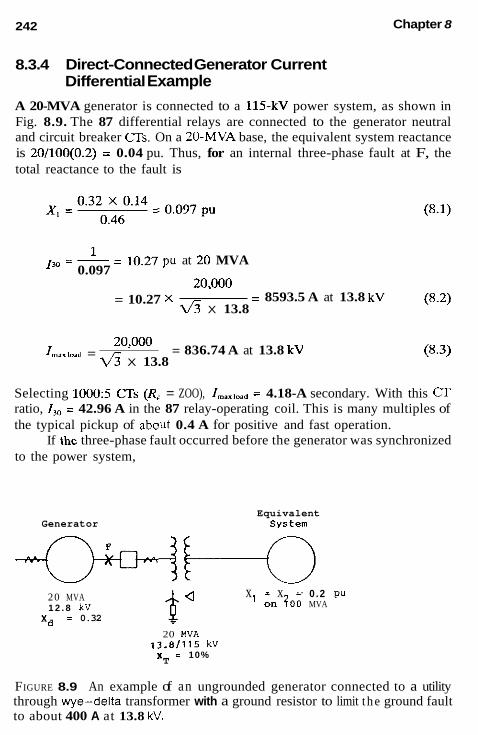
242 Chapter 8
8.3.4 Direct-Connected Generator Current Differential Example
A 20-MVA generator is connected to a 115-kV power system, as shown in Fig. 8.9. The 87 differential relays are connected to the generator neutral and circuit breaker CTs. On a 20-MVA base, the equivalent system reactance is 20/100(0.2) = 0.04 pu. Thus, for an internal three-phase fault at F, the total reactance to the fault is
I - 10.27 pu at 20 MVA 3o - 0.097
(8.2) 20'ooo
4 X 13.8 = 8593.5 A at 13.8 kV = 10.27 X
20'ooo ~ = 836.74 A at 13.8 kV X 13.8
I,",.e.d = (8.3)
Selecting 10005 CTs (R-. = ZOO), I,,,,,.= = 4.18-A secondary. With this C T ratio, 130 2 42.96 A in the 87 relay-operating coil. This is many multiples of the typical pickup of about 0.4 A for positive and fast operation.
If the three-phase fault occurred before the generator was synchronized to the power system,
Equivalent Generator system
x - x - 0.2 PU ' in f o i MVA $" 20 MVA 1 2 . 8 kV
Xd = 0.32
20 MVA 13 .81115 kV x i 10% T
FIGURE 8.9 An example of an ungrounded generator connected to a utility through we-delta transformer with a ground resistor to limit t he ground fault to about 400 A at 13.8 kV.

Generator Protection 243
130 = 1/0.32 = 3.13 pu = 2614.8 A at 13.8 kV
= 13.1 A through the 87 operating coil (8.4)
Again multiples of pickup are needed for good operation. The transformer of Fig. 8.7 is grounded on the generator side through
a 1942 resistor. This limits the phase-to-ground faults to just over 400 A. For an internal ground fault at F,
IOg = 400/200 = 2.0 A through the operating coil (8.5)
With the 87 phase relays set to operate at 0.4 A, the solid ground fault of 2.0 A is five times the relay pickup. Thus, ground fault protection is provided, but should he supplemented with 50N/51N overcurrent relays con- nected in the grounded neutral.
8.3.5 Phase Protection for Small Generators That Do Not Use Differential
Where small power sources are connected to a large system, proteclion for phase faults in or reflected in the ac circuits of these small sources can be obtained from instantaneous overcurrent (50) or time overcurrent (51) relays. These are connected in the interconnecting phases to operate on fault cur- rents supplied by the large system. Because these relays are nondirectional, they must he coordinated with upstream devices for which the small gen- erators can supply fault current. This contribution may not exist for some power sources; they usually exist only for a short time for induction gen- erators (see next paragraph), or be relative small for synchronous generators. Also the current supplied by synchronous generators will decrease with time, from suhtransient, to transient, to synchronous, as illustrated in Fig. 4 .6~ .
Induction generators need external sources for excitation. When a fault occurs and reduces the voltage, they generally provide a very short-time contribution to faults, as do induction motors (see Fig. 4.6d). If they are islanded with other induction and synchronous machines, it is possible that the system can supply necessary excitation for the induction generator to continue to supply a fault.
Ground relays may also he used if the large system can supply ground- fault current. This will be covered further under ground protection.
This protection is not operable if the small generator is ungrounded and is not connected to the large system.

244 Chapter 8
8.3.6 Unit Generator Current Differential (87) Example for Phase Protection
Consider the unit-connected generator tied to a 345-kV power system as shown in Fig. 8.10.
For a three-phase fault on the 18-kV.bus at F,, the positive-sequence network is shown and the total reactance to the fault is calculated as
(0.515) (0.485)
= 0.064 pu '0.131' X '0.124
0.255 x,,:, =
These values are per unit on a 100-MVA base. The values in parentheses define current distribution on either side of the fault. For a solid three-phase fault,
I,, , = I", , = __ - - 15.70 pu (8.7) 0.064
loo'ooo = 3207.5 A at 18 kV = v5 x 18
I,, , =I,, , = 15.7 x 3207.5 = 50,357.3 A at 18 kV (8.9)
The maximum load on the unit is
160'ooo = 5132 A at 18 kV v5 x 18 Imax,"d = (8.10)
From this maximum load, a current transformer ratio of either 55005 or 60005 could be used. The lowest ratio is preferred for increased sensitivity, so suppose that 55005 (11OO:l) is used. This gives a full-load secondary current of 5132/1100 or 4.67 A.
The three-phase secondary fault current is
I,,. , = I., , = __ 50'357 - - 45.78 A-s 1100
(8.11)
If the fault F, is inside the 87 differential zone (see Figs. 8.5 and 8.10) this 45.78 A would flow through the operating coil. This is many multiples of the differential relay pickup current for positive and fast operation.
For the external fault F, as shown, the currents through the restraining windings of the differential relay would be only that contribution from the generator, which is
50,357.3 X 0.485 = 22.2 A-s 1100 = (8.12)

Generator Protection 245
N. ~ositive seouence Network
(b)
FIGURE 8.10 Typical example of a unit generator (same system as Figure 7.1 1 example).

246 Chapter 8
This would he the internal and total fault current if a three-phase fault oc- curred before the unit were synchronized to the 345-kV system. For these cases the fault current can be calculated alternatively as
1.0 l , P l g E n = ~ - - 7.62 pu
0.131 = 7.62 X 3207.5 = 24,438.11 A at 18 kV
24,438.1 1100
- - = 22.2 A-s (8.13)
8.4 UNIT TRANSFORMER PHASE-FAULT DIFFERENTIAL PROTECTION (87TG)
Again, differential protection is recommended and is shown as 87TG in Fig. 8.5. Because there is no breaker between the generator and the transformer, this differential is connected to include the generator, for both units must be tripped for either transformer or generator faults. This provides added gen- erator protection. Thus, for generator phase faults, 87 and 87TG operate in parallel. In large generator units, an additional differential 87T is sometimes connected around the transformer. Thus, two primary protective systems are provided both for the generator, as shown, and for the transformer (only one 87TG shown). The connections and relays for transformers are discussed in Chapter 9.
In Fig. 8.5 the high-side CTs on the unit auxiliaries transformer should be included in the 87TG differential, so that faults in the unit auxiliary transformer (UAT) and 4.16-kV system are external. Alternatively, low-side unit auxiliary transformer C T s could be used so that the UAT transformer is within the 87TG protection zone. The same alternatives exist where an added (and recommended) 87UAT differential protection is applied.
It is important to recognize that including the unit auxiliary transformer in either the 87TG or 87T zones usually does not provide good or adequate protection for the transformer. This can be demonstrated by considering a solid three-phase fault on the low 4.16-kV side of this hank or at FZ in Fig. 8.10. For this fault the total positive-sequence reactance of the system plus the transformer is
(8.14) 100 15
X,,, = 0.064 + 0.08 X - = 0.064 + 0.533 = 0.597 pu
1 .o 0.597 I,,, = = ~ = 1.675 pu
= 1.675 x 3207.5 = 5372.7 A at 18 kV (8.15)

Generator Protection 247
In the overall differential, the equivalent CT ratio will be basically close to 1100:1, so with this ratio, this fault F2 will be 5372.7/1100 = 4.88-A sec- ondary. The transformer differential relays are less sensitive because they must be applied to different types and ratio a s , avoid operation of mag- netizing inrush, and so on. For most relays this 4.88 A is probably above its minimum pickup, but the low value of fault provides very low multiples of pickup and marginal sensitivity.
This illustrates and emphasizes that a separate transformer differential relay is recommended for the unit auxiliary transformer(s), as shown in Fig. 8.5. For this application, the maximum transformer current would be
15’000 = 481.13 A at 18 kV v3 x 18 IUAT rndl lord = (8.16)
Thus, a C T ratio of 5 0 0 5 could he used for 87UAT, rather than the equiv- alent 11OO:l ratio required for 87TG. With an equivalent 5005 (lOOl), fault FL would provide an operating coil current of 5372.7/100 = 53.73, a good margin for fast and sensitive station transformer fault protection. The 87UAT relays must also shut down the generator and open the 345-kV breaker.
For generators connected as shown in Fig. 8.2, the unit auxiliary trans- former(s) are connected to the generator bus, usually either with or without a breaker to the bus. A separate differential can be used for the transformer, or without a high-side breaker, included in a bus-transformer differential.
Pressure relays, discussed in Chapter 9, are recommended for all trans- formers. These supplement differential protection, but can operate only for faults inside the transformer tank.
8.5 PHASE-FAULT BACKUP PROTECTION (51V) or (21)
Backup protection for the generator and connected system can be provided by a voltage-controlled or voltage-restraint time-overcurrent relay (51V) or by phase distance relays (21). These two types are in wide use, with 51V generally applied to medium and smaller generators, and 21 for large-unit generators.
8.5.1 Voltage-Controlled or Voltage-Restraint Time-Overcurrent (51V) Backup Protection
This is a nondirectional relay; therefore, it can be connected to CTs at the terminal as in Fig. 8.3 or at the neutral end as in Fig. 8.5. Voltage is from the generator VTs and is used to prevent the time-overcurrent unit from operating until a fault decreases the voltage.

248 Chapter 8
Generators are normally operated close to the knee of their saturation curve. The synchronous reactance-governing load, X,,,,, is a lower value than X4unmo for faults that reduce the voltage at the generator. Thus, the substained three-phase fault current is less than the maximum-load current, as long as the voltage regulator does not increase the substained fault- reduced voltage.
The voltage-controlled type prevents the overcurrent unit from oper- ating until the fault reduces the voltage to a specific value, typically about 80% of normal. The voltage-restraint type changes the time-overcurrent pickup to decrease with decreasing voltage. Both allow the overcurrent unit to operate at currents below normal voltage maximum load. Thus, sustained three-phase current below full load can be detected.
The voltage-controlled type with an adjustable fixed pickup, typically 50% of rated current, is easier to set and coordinate with other relays. On the other hand, the voltage-restraint type is less susceptible to unwanted operations on motor-starting currents and system swings. However, the short-time voltage depression caused by these probably would not result in the time-overcurrent operation.
Generally, the 51V overcurrent unit is connected to one phase with a phase-to-phase voltage for three-phase fault protection. A negative-sequence (46) relay provides protection for unbalanced faults. The 51V must be time- coordinated with any system relays it can overreach.
8.5.2 Phase-Distance (21) Backup Protection
On large generators, especially the unit types, phase-fault backup is usually provided by phase-distance units (21). When connected to CTs on the neutral side, as in Fig. 8.5, and set through the generator into the system, backup is provided for both the generator and system. When using a three-phase type 21 relay, the phase shift of the transformer does not affect the reach, as it does for single-phase-type units. Voltage is obtained from the VTs at the generator terminals.
For distance relays, the location of the CTs determine the directional sensing, whereas distance is measured from the location of the Ws. Thus, if C T s at the generator leads were used, backup could be provided only for the system or for the generator, not both, depending on the connections. When it is set looking into the system, a fixed timer provides the necessary time delay to coordinate with all the relays its setting overreaches. If it is set looking into the generator, no timer is required.
An alternative connection is to connect the distance relay to CTs and VTs at the generator system bus and set it looking through the unit trans- former into the generator. No time delay is required. This provides high-

Generator Protection 249
speed backup for only the unit transformer and generator, but not for the connected system.
8.6 NEGATIVE-SEQUENCE CURRENT BACKUP PROTECTION
Negative sequence in a generator crosses the air gap and appears in the rotor or field as a double-frequency current. This tends to flow in the surface of the rotor structure, the nonmagnetic wedges, and other lower-impedance areas. Severe overheating and, ultimately, the melting of the wedges into the air gap can occur, causing severe damage.
Power systems are not completely symmetrical and loads can be un- balanced so that a small amount of negative sequence is present during normal operation. ANSI standards permit continuous I, currents of 5 1 0 % in generators and also short-time limits expressed as fit = K, where I2 is the integrated negative-sequence current flowing for time I in seconds; K is a constant established by the machine design. Typical values for synchronous condensers and older turbine generators were 30-40, but for the very large generators K may be as low as 5-10. Units subject to the specified limit and up to 200% of the limit may be damaged, and early inspection is rec- ommended. For more than ZOO%, damage can be expected.
Inverse-time-overcurrent units, operating from negative-sequence cur- rent and with a time characteristic adjustable to I:t = K, are recommended for all generators. This protection (46) is shown in Figs. 8.3 and 8.5. They are set to operate just before the specified machine I:t = K limit is reached. A low-level I, auxiliary is available, operating typically at about 0.03-0.2 pu I, for warning continued unbalance.
Basically, this protection is backup primarily for unbalanced system faults that are not adequately cleared, but it also backs up the protection for the generator unit and associated equipment.
8.7 STATOR GROUND-FAULT PROTECTION
Insulation failure is the major cause of most faults in a generator. They may start as turn-to-turn faults and develop into ground faults, or start as ground faults initially, so ground-fault protection is very important, although fortu- nately, such faults are relatively rare.
Generator grounding may be one of three general types.
1. Generator neutral grounded a. Low-impedance (resistor or reactor), nominally 50-600 A
primary

250 Chapter 8
b. High-resistance or resonant, generally 1-10 A primary c. Solid for very small units
nominally 50-600 A primary Generator and the connected system ungrounded
2. Generator low-impedance grounded by the connected system,
3.
Operation of breakers or other disconnecting means can result in cat- egory 2 becoming category 3.
Type l a is widely used for medium and small units, and l b for large utility units and critical process industrial generators.
Independent power producers may use all types. Smaller power sources frequently use la , 2 or 3, with lc for some very small sources.
Except for some small generators, the zero-sequence reactance is smaller and more variable than the positive- and negative-sequence values. Thus, solid ground faults will be higher than phase faults. The general prac- tice is to limit ground-fault current by resistance or reactance in the neutrals of the ground connections. The fundamentals of grounding have been cov- ered in Chapter 7.
8.7.1 Ground-Fault Protection for Single Medium or Small Wye-Connected Generators (Type la: see Figs. 8.3 and 8.1 1)
With low-resistance (or reactor) grounding, the 87-phase differential may provide some protection as was illustrated in the example in Section 8.3.4.
GENERATOR
--+ --+
b
c
FIGURE 8.1 1 using a directional ground-overcurrent relay.
Ground (zero-sequence) differential protection for a generator

Generator Protection 251
In these cases, supplemental or backup protection is provided by a time- overcurrent relay 51G in the grounded neutral. Where the differential does not provide protection the 51G is the primary ground-fault protection. The CT primary rating should be about one-half of the maximum ground-fault current with the 51G set at approximately 0.5 A. Time coordination is nec- essary with other ground relays that may be overreached.
Higher sensitivity and fast operation for ground faults may be obtained by an additional zero-sequence differential. One type that is relatively in- dependent of the CT ratios and CT performance is shown in Fig. 8.11. A product-type overcurrent relay, 87GD, operates on the product of the two currents. As can be seen from the figure, for an external fault the relay currents are in opposition, and the relay does not operate. For internal ground faults, zero-sequence from the system reverses to provide operation. One type of relay has a minimum pickup of 0.25 product or 0.5 A in each coil. With maximum-operating energy with the two currents in phase, the relay will operate with higher currents out of phase t 90” and with different magnitudes as long as the product times the cosine of the angle between the currents is greater than the tap product. If the system is not grounded, the scheme, as shown in Fig. 8.11, will not operate, because the system does not supply zero-sequence current to the internal fault. In this case, an aux- iliary current transformer can be used to provide internal operating energy with only one zero-sequence source. This is discussed in detail in Section 9.17.
8.7.2 Ground-Fault Protection of Multiple Medium or Small Wye- or Delta-Connected Generators (Type 2; see Figs. 8.2 and 8.12)
When several wye-connected generators are connected to a common bus, such as in Fig. 8.2, it becomes difficult to selectively isolate the fault for minimum system disruption. Whether one or all generator neutrals are grounded similarly, the fault current in the grounded neutrals is essentially the same, independent of fault location in the area. That is, for faults in the generator-to-breaker area, on the bus, or in the system just beyond the bus, the fault level in the grounded materials is basically the same. This is true for any of the grounding systems.
With low-impedance grounding and sufficient current to operate the differential relays of the generator and bus, proper minimum isolation can be achieved. Then 51G in the grounded neutrals provides backup or “last resort” protection, which may be nonselective. Another possibility is to apply sensitive ground directional relays set looking into the generator, at the terminals of the generators. These would operate only for ground faults

252 Chapter 8
A
5ONl5lN I
U S O N l 5 l N
F i ~ u ~ ~ 8 . 1 2 Ground-fault protection for ungrounded generators grounded by the connected system. Other types of protection, such as in Fig. 8.3, are not shown.
within the machine and not respond to faults in the other machines, bus, or the system. Again 51G in the grounded neutrals provides nonselective backup. This application may be impossible or difficult with high-impedance grounding.
Grounding only one of the generators with an ungrounded system pro- vides the liability of operating ungrounded when that unit is removed from service either manually or through its protection. Suppose only one unit is grounded. If a ground fault occurs in the grounded unit, a 51G relay (as in Fig. 8.3) will provide protection. However, if the fault is in one of the other generators, the grounded generator 51G may operate but the 51N of the faulted generator would not see the fault if connected to CTs in the neutral side. Thus, multiple grounding of each unit should be used to avoid un- grounding by fault tripping or a failure to transfer grounding on a planned shutdown of the only grounded unit.
A good method is to ground the main transformer as in Fig. 8.12, or if this transformer is delta on the generator side, to provide a separate grounding wye-delta transformer connected to the bus and used only for grounding. It would be sized for the fault-limiting required. 51N/50N ground relays connected to the terminal-side CTs provide ground protection for each unit. 51G in the neutral provides ground protection for the transformer and bus with backup for the 50N/51N relays.
8.7.3 Ground-Fault Protection for Ungrounded Generators
Ground faults in an ungrounded system (type 3) are easy to detect, but essentially impossible to locate by relays. A n overvoltage relay (59) con-

Generator Protection 253
nected across the broken delta of wye-grounded VTs provides 3V0 voltage for a ground fault (see Fig. 7.5, Sec. 7.4.1).
This protection should be added wherever the possibility for an un- grounded condition exists by switching or islanding.
8.7.4 Ground-Fault Protection for Very Small, Solidly Grounded Generators
Ground-fault protection is the same as shown in Fig. 8.3.
8.7.5 Ground-Fault Protection for Unit-Connected Generators Using High-Impedance Neutral Grounding (Type 1 b; see Fig. 8.5)
High-resistance grounding is widely used for unit-connected generators. The resistor, as discussed in Section 7.5.2, limits ground faults to about 1- to 10-A primary. At these levels a ground fault in the generator will have minimum iron burning to avoid costly repairs. An overvoltage relay (59G) is connected across the resistor to respond to the V, voltage for faults in the generator and system, up to the delta windings of the unit and station service transformers. The example in Section 7.5.3 (see Fig. 7.11) illustrates that, for a solid line-to-ground fault at the generator terminals, the voltage across the resistor will he 138 V, which is quite typical. The 59G relay with pickup values from 1 to 16 V provides good sensitivity, protecting approximately 90-95% of generator windings. These relays must be insensitive to third harmonics, which normally flow in the neutral in a manner similar to zero sequence.
For resonant-grounding systems (see Sec. 7.5.1, Fig. 7.8), used in a few cases for unit generators, a 59G relay should he applied across the grounding reactor and through a suitable voltage transformer if a primary reactor is used.
With these grounding systems, the sensitive (59G) relays should be coordinated with the vollage transformer’s primary fuses. If this is not pos- sible or practical, recognize that the unit may be tripped for VT faults. Although these faults are quite possible, the probability is generally very low. Coordination is also important in some applications to avoid misoper- ation for ground faults on the high-voltage side of the power transformer. This is discussed in a later section.
Frequently, the voltage transformers are wye-wye, but open-delta- connected VTs can he used for three-phase voltage. With wye-wye VTs, the primary wye should be grounded. Unless the secondary is required for zero-sequence indications, the secondary wye should be ungrounded and isolated. Grounding one of the phases provides a safety ground. Otherwise,

254 Chapter 8
the 59G may operate for secondary V T circuit ground faults, and 59G should be coordinated with the secondary VT fuses.
Inverse-time-instantaneous overcurrent (50/51) relays in the resistor secondary circuit (Fig. 8.5) provide alternative or backup ground protection. The secondary CT ratio is selected to give approximately the same relay current as that flowing in the generator neutral for a ground fault. Thus using the Fig. 7.11 example, a CT ratio of 4005 (801) would give
464.38 80
I 5 0 m = ~ - - 5.80 A (8.17)
where the primary fault current in the neutral was 6.19 A, which reflected through the distribution transformer as 464.38 A.
These relays must be set higher than the maximum unbalance current that normally flows in the neutral circuit. Typical values usually are less than 1 A in the generator neutral. Settings for 51 should be 1.5-2 times this unbalance. The 50 relay provides instantaneous protection, and it must be set above the normal neutral unbalance as well as above the maximum current resulting from primary system ground faults, whichever is greater. Section 8.7.2 discusses the latter type fault. Typical 51 settings should be two to three times the maximum.
In some applications two 51 relays are used, one to provide backup tripping of the unit, the other to initiate breaker failure relaying (when used) associated with the primary breaker, as shown in Fig. 8.5, or breakers if the primary is connected to a ring or breaker-and-half arrangement.
8.7.6 Added Protection for 100% Generator Ground Protection with High-Resistance Grounding
As indicated, the 59G overvoltage across the grounding resistor provided about 90-95% ground protection for the generator windings. Additional protection is required for ground faults that may occur near the neutral end of the stator winding. Several methods exist and are of two basic types: (1) use of the third-harmonic voltage, or ( 2 ) the injection of a subharmonic voltage.
1. Normal operation of generators produces harmonics with the third harmonic being the major one. This harmonic behaves similarly to zero-sequence. With the generator connected to delta or un- grounded-wye transformers, the third harmonic cannot pass through the transformer wye-grounded winding and circulate in the delta. Thus, it appears across the ground resistor or across the broken-delta-connected VTs normally used for 3V0 indications. Typical third-harmonic voltages (Vt8,,) are shown in Fig. 8.13

Generator Protection 255
180 HVA Generator 16.5 k V
165 MYR Generater 60 MvA Generator 13.8 kV 13.8 kV
Terminal %"180
2
1 Minimum Load
Neutral Y b"180
Terminal *"l80
Minimum Load
7 7 Neutral
%"180
Neutral %"180
FIGURE 8.13 Third-harmonic phase-to-ground voltages measured on three large generators at maximum and minimum load. Values in percentage of rated machine phase-to-ground voltage. The left and center generators were hydro and the right a thermal unit.
a. One protection scheme connects an undervoltage relay (27) responsive to third harmonics in parallel with 59G as shown in Fig. 8.5. Its normally closed contact is in series with a voltage-sensing (59) relay connected to the generator VTs. Typical 59 relay settings are about 90% of normal voltage. In normal operation the 27 relay contacts are opened by the third- harmonic normal voltages, and the supervising voltage relay 59 contacts are closed. When a ground fault occurs near the generator neutral the third-harmonic voltage is shorted out, or is significantly reduced to dropout the 27 relay, closing its contacts. With the supervising 59 contacts closed an indication of generator 60-HZ voltage, a ground fault is indicated. Another scheme applies an overvoltage 59 relay that is re- sponsive to the third harmonics across the broken-delta gen- erator VTs. This must be set at a value above the maximum
b.

256 Chapter 8
normal third-harmonic voltage. For the neutral-area ground faults, the third-harmonic voltages will be redistributed and increased at the generator terminals. This scheme may offer limited protection when the normal full-load third-harmonic voltage is high, and time coordination is used to avoid oper- ation for higher third-harmonic voltage during external faults. The third-harmonic voltage at both the neutral and generator terminals can vary considerably from maximum to minimum load. Generally, the third-harmonic voltage at maximum load will be at least 50% greater than at minimum load, with var- iations of about 2:l to 5:l. In many cases the ratio of the neutral-to-terminal third-harmonic voltage is reasonably con- stant with load changes, so another scheme operates on the differential voltage between the two ends of the winding. Ground faults near the neutral and near the terminals upset the balance, through the fault reducing the third-harmonic voltage at the faulted end. This provides operating overvoltage for relay 59D (see Fig. 8.5).
All these schemes require specific data for the third- harmonic voltages over the operating ranges of the generator, both real and reactive power, before the relays can he set prop- erly. One scheme may he more sensitive for one generator, but less sensitive for other generators.
2. The injection of subharmonic frequency current can be by a sep- arate neutral transformer or through the broken-delta VT connec- tion. Some systems provide coding for increased security. A ground fault decreases the generator capacitance to cause an in- crease in current for detection. These schemes provide the possi- bility of 100% winding protection and monitoring capability. This neutral or 100% winding ground-fault protection is a relatively new area, so considerable investigation and study are still in progress.
c.
8.7.7 High-Voltage Ground-Fault Coupling Can Produce V, in High-lmpedance- Grounding Systems
Ground faults in the primary system produce a voltage in the generator secondary circuit through the primary-to-secondary capacitance of the unit transformer hank. The circuit is shown in Fig. 8.14. With sensitive voltage relays (59G) applied in high-resistance systems, this voltage can cause op- eration. Thus 59G relays should have a time delay to permit the primary

Generator Protection 257
Generator ""it Transformer
I I,
,I
1, - -: - x j c 3R
1 3
A
"0.3
V
b
c
Capacllance Between Transformer Prlmlcy
\ and Secondary Wlndlnqs - _ - - -
D i s t r i b u t i o n s y s t e m Transformer Oistributed and Groundins Capacitance

258 Chapter 8
ground relays to clear high-side faults if the coupling voltage is greater than the 59G relay pickup.
This can be illustrated with the example of Fig. 8.10. Assume that the transformer capacitance between the primary and secondary windings (X,) is 0.012 pF/phase. Using the values of 3R = 5019 R from Fig. 7.11, the voltage across the grounding resistor is calculated as shown in Fig. 8.15. Calculation of the currents for a phase-a-to-ground fault on the primary 345- kV bus is shown in Fig. 8.15a. Figure 8.15b shows the calculation for a primary V, fault voltage of 81,467 V, which reflects through the intenuinding capacitance to produce 1293 V across the grounding distribution transformer primary. With a 18240 kV ratio, relay 59G receives 17.24 V. This is above the pickup, so the relay would receive operating energy until the 345-kV
Per Unit on 100 UVA
I . 8 8 2 l i . 118)
x =X = . 225x .O3 = ,026 pu 1 2 7
i . 6 1 1 i.391 x = - 0 9 4 x . 0 6 = .037 P U 0 - . 1 5 P
I1=I2=I0= 1.0 = 11.17 pu . 026+ . 026+nTi
(a)
FIGURE 8.15 Example of a primary line-to-ground fault producing voltage across the high-impedance grounding system: (a) sequence networks and fault circulation: (b) grounding network and voltage calculation.

Generator Protection 259
= -j221,049 ohms
I X = 11.17x.037=.409 pu
VOa
0 0
= .409 345,000 =-j81.467 volts at 345kv
3R(-'Xc1 (5019) ( - j 5 0 1 9 1 ~ 'OL = 3R-.i 5019 - j5019
=I549 @ ohms I C 6
V0a 'OT = ZoL-jXcT
"OR = 'OT'OL = vo"oL = 3 5 4 9 x .364 = 1293 volts at l6kV zo~-jxcT
Ink" = = 1 7 . 2 4 v o l t s on re lay 5 % ratio
(b)
FIGURE 8.15 Continued
fault is cleared. These high-voltage faults normally are cleared at high speed, hut 59G should be coordinated with the maximum backup time.
If resonant grounding is used for the generator, the primary ground fault may also affect the protection system. For the lower-voltage system, this coupled voltage probably will not be significant, as the V, for primary- side faults will he much lower than on the EHV systems.
8.7.8 Ground-Fault Protection for Multidirect-Connected Generators Using High-Resistance Grounding
Where multiple operators are connected to a common bus, as in Fig. 8.2, or in industrial systems where faults can result in a costly interruption of pro- cesses, the high-resistance grounding by three distribution transformers, as discussed in Section 7.5.2, may be used. Grounding exists independently of the generators in service. In the example of Section 7.5.4, Fig. 7.13, 208 V was available to operate relay 59G connected across the grounding resistor to provide good fault sensitivity.
Because the system is otherwise ungrounded, sensitive 310 fault detec- tors in the various circuits connected to the bus can provide location of the fault.

260 Chapter 8
8.8 MULTIPLE GENERATOR UNITS CONNECTED DIRECTLY TO A TRANSFORMER: GROUNDING AND PROTECTION
Most often these are large tandem or cross-compound units operating from a common steam prime-mover source. The two units may he paralleled and connected to a common delta-unit transformer winding, or each generator may be connected to separate delta windings on a three-winding-unit trans- former. For the first or paralleled connection, only one of the generators is grounded, usually with high-impedance grounding. The other unit is left ungrounded. Ground faults in either unit will operate the ground protection as discussed earlier. The location of the fault will not be indicated, because the fault current level is practically the same for all fault locations. Both units must be shut down, for there is no breaker to isolate the two units.
With the generators connected to separate transformer windings, each unit must he grounded for ground protection. Separate generator protection should he applied to each generator unit. Without breakers between the gen- erators and transformer, the overall transformer differential protection must he of the multirestraint type and connected as discussed in Section 9.8.
Each unit should have loss-of-field protection (40). Only one negative- sequence (46) and one distance (21) or three-phase (51V) relay for backup protection are necessary, and they can he connected to either unit. This is based on both units operating together at all times. If one unit can be op- erated with the other shut down, each unit should have complete protection, as outlined on the foregoing and summarized in Fig. 8.5.
8.9 FIELD GROUND PROTECTION (64) Ground detection for the exciter and field are important and usually supplied as part of that equipment, rather than applied by the user. However, if not supplied, or if additional protection is desired, protective relays are available.
For units with brushes, a relay (64) with a voltage-divider circuit can be connected across the field and exciter with a sensitive dc-type relay con- nected between the bridge network and ground. When a ground occurs in the field of exciter circuits, a voltage appears across the relay to produce operation. To avoid no-operation for a ground fault at a null point, one branch of the bridge includes a nonlinear resistor that changes this blind spot with voltage variations of the field.
Generators with brushless exciters are supplied with means to drop pilot brushes on slip rings to measure the insulation level of the field on a periodic basis. The insulation of the exciter field is checked continuously.

G e n e rato r Protectio n 261
Both these norrnally provide an alarm for operator action, but can stiil be used to trip if desired.
8.1 O GENERATOR OFF-LINE PROTECTION
All the protection should be examined to see if it is operable during the process of bringing the unit up to rated speed and voltage for synchronizing to the power system. For some units, such as steam turbines, This process can include operation at reduced frequencies for severa1 hours. Thus the protedion should be active from about one-fourth to one-haif rated fre- quency and higher. When the reIays or instrurnent transformer's performance is impaired at these iow frequencies, suppiemental ternporary protection should be provided.
8.1 1
8.77.1
REDUCED OR LOST EXCITATION PRQTECTION (40) - . - .
- .
iuss of Excitation Protection with Distance (21) Relays _ _ . _
- Protection to avoid unstable operation, potential loss of synchronism, and possible damage is important and is applied for ai1 synchronous machines. Such protection is included in the excitation system supplied with the ma- chine, but adcfitional protection is recommended to operate independently both as suppiemental and backup protection. Distance relays, as outlimed in ehapter 6, ãre applied for this purpose.
NormaIiy, the generator fieId is adjusted so that slightly lagging power is shípped into the system. Figure 8.16 provides:an overview of synchronous machine operation. Lagging power shown in the first quadr i t is the normal operating area. When the excitation (field) is reduced or iost,'.the current moves into the fourth quãdrant, where the system must supply the missing reactive power. Synchronous generators have low or reduced stability in this area. If the systern can supply sufficient inductive reactive power without a large voltage drop, the unit may run as an induction generator. Othenvise, synchrankm is lost. This change is not instantaneous, but occurs over a time period depending on the unit and connected system. If the field was acci- dentally iripped, early alarm may permit the operator to restore it and avoid a costly and time-consumíng shutdown and restart. If the field is not promptly restorâbie, the unit should be shut down.
Generators have characteristics known as capability curves. Typical curves are sbown in Fig. 8.17a. Temperature limits are basically zones, so these curves are the designer's thennal limit. As overheating varies with
.


262
- syn. - I
(OverexciIOà Areai
11
Isp. Motor Isading
Chapter 8
I
(Doderex'itsd Aval c
operation, three arcs of circles define the lirnits. In one area of operating, the limit is the overheating in the rotor windings; in another, in the stator windings; and in the third, in the stator iron.
As indicated earlier, generators should be operated cautiously in the leading 01 negative reactive zone. The added lirnit here is the steady-state stability limit (SSSL). This is defined as a circle arc where the offset (center) and radius are
(Indudicn Genorator)
1 Center offset = - V 2 (id - - i) - volt amperes
1 2
Radius = - V' (i + i) volt amperes
(8.18)
(8.19)
where Vis the generator line-to-neutra1 terminal voltage, X, the total equiv- alent impedance of the wnnected system, and X, the synchronous unsatu- rated reactance. These are power limits usually expressed in per unit, with X, and X, on the generator base.

Generator Protection 263
Ibl
f=Y Distance Relay settings
Reactive PDrer notor into system Wind i ng
Limited
la1
stator Winding Limited
Real P o w e r
WKVA (not per unit) into system
Underexcited
MVAR Steady-State Stability Limit
~eactive ~ w e r Stator End into ene era tor Iron Limited
X Ohms . A r e a of Normal
, --,Directional unit When Used
Steady - State \ : Stability Limit \ . \ . , *. \ .
Limiter ..
- X Ohms
F i ~ u ~ 1 ~ 8 . 1 7 Typical power capability and stability curves for a generator and their conversion to an R-X diagram for (40) relay protection application: (a) capability and stability curves on power axes: (b) power curves transferred to R-X axes with distance-type relay protection.

264 Chapter 8
This steady-state stability curve is typically as shown in Fig. 8.17a. It will vary with the generator and with the system connected, as well as with the voltage. Although the system and voltage will vary during operation, these are usually relatively small for a given system.
The generator excitation system has a minimum excitation limiter (also known as the underexcited reactive ampere limit) to prevent the exciter regulator from reducing the field below its set point. This is typically set just above the steady-state stability (see Fig. 8.17b).
For application of a distance relay, these power curves must be con- verted to impedances for plotting on the R-X axes. This conversion of Eqs. (2.17) and (6.7) is
kV2 R, MVA R,,
Z,. secondary ohms (8.20)
R, and R,. are the respective current and voltage transformer ratios used for the distance relay. If the plot is made in primary ohms, the R,IR., factor would not be used. From a value of MVA at the angle indicated from the capability curve, Eq. (8.20) converts this to ohms. This converted value is plotted on the R-X diagram at that angle. This conversion is shown in Fig. 8.17b for both the underexcited capability curves and the stability curve. For the stability curve the conversion can be made easier if the values of X, and X, are known. Then the stability circle center (offset) from the origin is 1/2(Xd - X,) and the radius is 1/2(Xd + X,). If the plot is in secondary ohms, X, and X , must be in secondary ohms per Eq. (8.20).
In the R-X diagram of Fig. 8.17b, the origin is at the generator ter- minals, with X, plotted below the origin and X, plotted above; also, that increasing or higher power is indicated by a longer distance from the origin in Fig. 8.17a, but by the shorter impedance vector in Fig. 8.17b. Thus, in the power diagram (Fig. 8.17a), safe-operating power is within the capability and stability curves, but outside the curves in Fig. 8.17b. The minimum excitation limiter operates on a power level less than the stability limit.
The normal-operating area is as shown in Fig. 8.17b. With reduced excitation or loss of excitation, the impedance phasor moves slowly as the flux decreases into the fourth quadrant. A distance relay (40) enclosing this area provides a good means of detecting this condition. Several setting modes are available.
1. For complete loss of field, the distance relay is set as illustrated by the smaller circle in Fig. 8.17b. The diameter is on the order of X,, with the upper part of the circle 50-75% of Xi below the origin. Xi is the transient reactance of the generator. The relay operates when the impedance vector moves into this circle. Operating times of about 0.2-0.3 s are used with a complete shutdown of the generator.
Z&, =

Generator Protection 265
2. To detect low excitation, partial loss, or complete loss, the diameter is set preferably inside the minimum excitation limiter setting, but outside the generator capability and stability limit curves. This is shown by the larger-diameter dotted circle. It is not always easy to make this setting as suggested; good judgment and compromise may be necessary. A directional unit is required to avoid operation of nearby faults and stable transient swings. Relay (40) operation is helow the dashed directional line and within the larger dashed operating circle. Where applicable, an undervoltage unit set to drop out between 87 and 80% of normal voltage is used to supervise the relay operation. If the power system can supply reactive power to the generator without a significant drop in voltage, an alarm is sounded for possible corrective action, followed by a shutdown trip after a time delay. Typical delays used vary with machine and system, but are 10 s to 1 min. If the voltage drops below the voltage unit setting, tripping is initiated with operating times about 0.2-0.3 s.
3. For large, important generator units, a combination of (1) and (2) is used by applying two (40) loss-of-field relays.
8.1 1.2 Loss of Excitation Protection with a Var-Type Relay
A directional power relay connected to operate on inductive vars from the connected system can be applied to detect loss of excitation. An application is shown in Fig. 8.18 where the relay has an 8" characteristic.
Normal synchronous generator operation is kilowatt (kW, MW) power with inductive vars flowing into the connected system. When the generator
-1Q .
FIGURE 8.18 Loss of excitation protection with a var-type relay.

266 Chapter 8
field is reduced or lost, the system will attempt to supply inductive vars to continue operation as an induction generator. Thus, the generator current will move into the leading area (vars from system) to operate the var relay typically as shown. A 0.2-s time delay is recommended to prevent operation on transient conditions.
8.12 GENERATOR PROTECTION FOR SYSTEM DISTURBANCES AND OPERATIONAL HAZARDS
In the previous sections the discussion has covered primary protection for faults in the generators and backup protection for uncleared or delayed faults using relays 21, 46, and 51V. Loss of excitation (40) may be caused by a rotor field fault or by inadvertent tripping of the field.
In this section problems and protection for other hazards that may be encountered as a result of system disturbances or operator errors are discussed.
8.12.1 Loss of Prime-Mover: Generator Motoring (32)
If the prime-mover supply is removed while the generator is connected to the power system and the field excited, the power system will drive the unit as a synchronous motor. This is particularly critical for steam and hydrounits. For steam turbines it causes overheating and potential damage to the turbine and turbine blades. Low water flow for the hydrounits can cause cavitation of the blades of the turbine. This can also occur by closing the steam or water flow valves too rapidly during a load-reduction phase or by tripping the turbine while not correspondingly tripping the generator breaker.
Typical values of reverse power required to spin a generator at syn- chronous speed with no power input in percentage of the nameplate kilo- watts are
Steam turbines, condensing types 1-3% Steam turbines, noncondensing types 3+%
Diesel engines -t- 25% Gas turbine 50+%
Various detection means are provided as part of the generator and its control, but a supplementary reverse power relay (32) is recommended and is shown in Figs. 8.3 and 8.5. The power directional relay is connected to operate when real power flows into the generator. Typical relay sensitivities with microprocessor relays are as low as 1 mA, which may be required
Hydro turbines 0.2-2+%

Generator Protection 267
when a generator can motor with partial prime-mover input. Operating time can be approximately 2 s.
8.12.2 Overvoltage: Volts and Hertz Protection (24)
Generators as well as transformers must not be subject to overvoltage except for short or transient excursions. With normal operation near the knee of the iron saturation curve, small overvoltages result in significant exciting cur- rents in transformers, and excessive flux densities and abnormal flux patterns in generators. These can cause severe and extensive damage.
The field excitation current, at rated output, is greater than that required at no-load, so it is important that the excitation be reduced correspondingly as load is reduced. Normally, this is accomplished by the regulating system, but incorrect voltage signals, loss of VT fuses, or other failures in these systems, can result in high overvoltage.
A particularly dangerous period is during the time when the generator is disconnected from the system and the speed is being changed. Generator voltage is proportional to frequency and the magnetic flux, so overvoltage protection should have a constant pickup as a function of the ratio of voltage to frequency, a volts-hertz (24) type. Protection supplementary to that in the generator controls is suggested using two-level volts-hertz units. One setting should be about 110%-rated voltage to alarm with a subsequent trip within approximately 1 min, the other set at near 120%-rated voltage to trip on the order of 6 s. A separate VT supply is preferable. The 24 unit is shown in Figs. 8.3 and 8.5.
Overvoltage (or undervoltage) can also occur when a generator con- nected to a distribution system is islanded with other loads. This is discussed further under Section 8.13.
8.1 2.3 inadvertent Energization: Nonsynchronized Connection (67)
In recent years several cases of severe damage of generators have resulted from the unit inadvertently being connected improperly to the power system. This can occur by incorrect closing of the circuit breaker while the unit is on turning gear, coasting to a stop, at standstill, or by improper synchroni- zation. The normal protection may operate in many cases, but not necessarily for all possibilities. This is an increased danger if some of the protection is not available or useful at low frequencies of start-up or shut-down. Because the unit or generator breaker(s) may be the problem, it is important that the adjacent breakers be opened promptly by local breaker failure or by remote tripping. Additional protection for this is provided by three directional, inverse-time-overcurrent units (67), one in each phase, connected to operate

268 Chapter 8
for reverse power into the generator. On the basis of current normally flow- ing out of the generator into the power system, the relay characteristics and connections should provide an operating zone from about 30"-60" through 180" (reverse power into the generator) to 210"-240" lead. Typical pickup should be about 0.5 pu current with 2.0 pu current-operating times of near 0.25 s. This application replaces motoring protection (32) and is more re- sponsive to the conditions just outlined. The 67 units are shown in Fig. 8.5.
8.12.4 Unbalanced Currents: Breaker Pole Flashover (61)
Where there is the potential for a pole flashover before synchronizing or after separation from the power system, additional pole disagreement pro- tection is recommended. This condition is likely to occur with no-fault and light-load, so the current can be very low. In one case a flashover of a 500-kV breaker pole of a 150-mi line which was open at the remote end resulted in sufficient charging current to maintain 70%-rated voltage at rated speed on the generator. I2 was 12% above the generator's rated current. This can be cleared only by prompt reduction of the excitation. Local backup and remote tripping of the far end of the line remove the system, but not the generator. Negative-sequence protection may respond, but with long re- sponse time, or it may not respond.
Sensitive protection (61) breaker pole failure (see Fig. 8.5) compares the magnitude levels in the three phases. It operates if one phase current is below a set value, while either of the other two are above its set value. Typical sensitivities provide operation if one phase current is less than 20-60 mA and the other above 40-200 mA. These are in the primary or high-voltage side of the unit transformer. A 3:l level difference with oper- ating times of about 112 s is suggested.
Where two high-side generator breakers are used, as in a ring or breaker and half buses, there can be enough normal unbalance circulating in the bus to operate this sensitive protection. For these applications the unbalance operation should be supervised by a zero-sequence voltage level detector, or a higher setting used.
8.12.5 Overload (49)
The generator control system usually provides protection from overloads. Where the generator has resistance temperature detectors (RTDs) within the windings, additional protection can be provided by a bridge network relay: High temperature in the unit unbalances the network and the relay operates.

Generator Protection 269
If RTDs are not available, a replica-type relay may be applied. Stator current through the relay produces replica temperatures to operate when they are excessive.
8.12.6 Off-Frequency Operation for Large Steam Turbines
Steam turbine blades are designed and tuned for efficient operation at a rated frequency rotation. Operation with load at different frequencies can result in blade resonance and fatigue damage in the long blades (18-44 in.) in the turbine low-pressure unit. Typical limits for 60-Hz machines with 18- to 25-in. low-pressure unit blades are about 58.8-61.5 Hz for continuous op- eration, hut, between 56 and 58.5 Hz, only 10 min of operation is permitted, accumulated over the entire lifetime of the machine. For turbines with 25- to 44-in. blades, the typical continuous range is between 59.5 and 60.5 Hz, 60-min accumulated lifetime between 58.5 and 59.5, and 10-min accumu- lated lifetime between 56 and 58.5 Hz. For these units underfrequency relays are suggested. One application uses a three-step unit, one set without time delay at 56 Hz, another at 58.4 Hz with a 2-min delay, and the third at 59.4 Hz with a 6-min delay.
8.12.7 Over- or Underfrequency (81)
Faults in the system can result in a system breakup into islands, which leaves an imbalance between available generation and the load. This results in either an excess or insufficient power for the connected loads. An excess results in overfrequency with possible overvoltage from reduced load de- mand. Operation in this mode will not produce overheating unless rated power and about 105% voltage are exceeded.
With insufficient power generated for the connected load, underfre- quency results with a heavy load demand. The drop in voltage causes the voltage regulator to increase the excitation. The result is overheating in both the rotor and the stator. At the same time, more power is being demanded with the generator less able to supply it at reduced frequency.
Utility Generators
For utility generators, the generator controls should promptly adjust the unit to the load demand, or system load shedding should adjust the load to the available generation before a critical situation develops.
Industrial and Independent Power Producers
When interconnected to a utility, the 81 underfrequency unit should be set at about 59.0-59.5 Hz and the 81 overfrequency unit at about 60.5 Hz in

270 Chapter 8
60-Hz systems. Time delay should be about 0.1 s and should be coordinated with underfrequency load shedding.
8.12.8 Undervoltage (27) or Overvoltage (59): Industrial and IPP Units
Undervoltage can occur if faults are not properly cleared or after a separation from the utility when the remaining load is greater than their capability. Typical settings for the undervoltage (27) relays are 90- to 95%-normal voltage, operating with about 1-s delay.
A major cause of overvoltage is the sudden loss of load. Power equip- ment involving iron (rotating generators, transformers, and such) operate close to the knee of their saturation curves. Thus small overvoltages result in large increases in exciting current and cause major damage. Qpical per- missible overvoltage at no-load are
Generators Transformer
105% continuous 110% continuous 110% 30 min 115% 5 min 125% 2 min
115% 30 min 120% 5 min 130% 3 min
Instantaneous overvoltage settings should be about 106- 110% of rated voltage to ensure prompt removal.
8.12.9 Loss of Synchronism: Out-of-Step
For many generators, being out-of-step is a system problem with the elcc- t r ia l center out in the transmission area. Once the voltages of the separate generation sources swing 180" apart, recovery is not possible, and separation must be made. Out-of-step detection and tripping is covered in Chapter 14. No relaying is normally applied at the generator in these cases.
With the larger generators and higher-voltage transmission, the system electrical center can move into the unit transformer and even into the gen- erator. For these systems, out-of-step protection at the generator must be added, for none of the other protection can respond adequately. The large circle setting of the loss-of-field unit (40) will operate for swings passing near and at the bus, and within the unit transformer and generator, but can pass out before the (40) relay times out. This separate protection is discussed in Chapter 14.
Generator Protection 271
8.12.10 Subsynchronous Oscillations
The application of series compensation in long EHV transmission lines pro- vides increased power transmission and stability but may result in suhsyn- chronous oscillations. This may also occur for a generator connected to a HVDC transmission line.
The natural frequency of a system (f.) with X, capacitive reactance and X , inductive reactance
(8.21)
where f, is the synchronous or normal system frequency. Since X, is less than X,, is subsynchronous. This results in problems in the system, par- ticularly in the generators. The rotor rotating at synchronous frequency is turning faster than the magnetic field produced by the subharmonic fre- quency. This results in a negative-slip and negative-resistance effect, with the generator tending to operate as an induction generator. When f, is close to f,, the slip is small, and the negative resistance large. If this resistance is greater than the system resistance, the circuit becomes self-excited, and the subsynchronous current magnitudes grow. This can cause overheating in the system. One solution is to use low-resistance pole-face damper windings to reduce the rotor resistance.
Another effect of the suhfrequency is to produce oscillating torques in the generator, with additional fransient torques occasioned by switching and faults in the system network. There is a danger that these torques may pro- duce rotor damage.
Various measures can he taken to mitigate this, and protective relays have been developed to detect subsynchronous resonance. One type mea- sures torsional motion, another senses the level of subsynchronous currents in the armature. This is a complex phenomenon and beyond the scope of this book, particularly as it occurs in only a few systems with series capacitance.
8.13 SYNCHRONOUS CONDENSER PROTECTION
Synchronous condensers usually operate as an unloaded motor to supply capacitive reactance to the system. Protection for these units is as shown in Fig. 8.3, with the addition shown in Fig. 8.5, as indicated by the system and operation requirements. The loss of field protection (40) should he set with its operating circle to enclose an impedance seen at the terminals with zero- excitation, or
1 IThon Cl.C"li
Z=- P U (8.22)

272 Chapter 8
Operation to supply capacitive reactance will operate the distance unit, but tripping is supervised by the voltage unit. No protection exists for inductive reactance into the system (overexcited), because the directional-sensing unit is open and the distance unit may or may not be operated.
8.14 GENERATOR-TRIPPING SYSTEMS
In general, immediate tripping is recommended for all faults in the generator and associated areas. This means opening the main and field breakers and closing the turbine stop valves or gates. Such action results in sudden and complete shedding of load which, particularly at full load, can be a severe shock to the mechanical systems. For phase and ground faults, except pos- sibly with high-impedance or resonant-grounding systems, immediate trip- ping is mandatory. With very limited ground-fault current, supervised or delayed tripping is sometimes used. The problem is always that any fault indicates damage and may develop to other phases, or a second fault may occur, all with the potential of a high increase in damage and danger. Even with immediate tripping the stored energy in the rotating mass continues the fault and damage for a considerable period.
The alternatives used to preferred complete immediate trip are (1) per- missive shutdown where the main field breakers are tripped afler the turbine stop valves or gates are closed, (2) alarm with fixed time-delay trip to permit operator action, and (3) alarm only. Again these are applicable only for ground faults when using high-impedance grounding, and as an individual system preference.
8.1 5 STATION AUXILIARY SERVICE SYSTEM
Power sources require auxiliary power for their operation, especially syn- chronous generators. This is supplied by a station service transformer as shown in Figs. 8.2, 8.4, and 8.5 to operate various pumps, fans, and such required in the operation of the generator. The secondary power-supply sys- tem is equivalent to a critical continuous process industrial plant. Protection of the transformers, motors, and feeders are discussed in later chapters.
An alternative power supply is provided. Continuous paralleling of the two sources is not recommended. Thus, a transfer from one source to the other preferably should be fast when an emergency occurs, to avoid decay of frequency and voltage during the dead period of transfer. An “open” transfer disconnects one source before the second is connected. In a “closed” transfer both sources are in service for a brief interval. An example of an open transfer is energizing the trip coil of one and the close coil of

Generator Protection 273
the other together. Because breaker closing is slightly longer than breaker tripping, a short period exists when both are open.
Closed transfer is required where the auxiliary motors do not have sufficient inertia to ride through a brief open period.
If a fast transfer is not used and motors are involved, the emergency source should not he applied until the voltage on the motors has declined to about 25% of rated.
A synchronism check (25) relay may he required and is recommended to assure that the two sources are in synchronism.
8.16 PROTECTION SUMMARY Generators, particularly very large units, are extremely critical to system operation and integrity. Thus, protection is very important for both depend- ability and security. Although, fortunately, fault incident is quite low, com- plete protection with reasonable duplication is well justified. This is the option of the particular system and individual circumstances, so any instal- lation can show variations from others.
As has been indicated, the protection devices of Figs. 8.3 and 8.5 discussed in the text are those applied by the user, in contrast with the protection supplied by the generator and prime-mover manufacturer. They are in common use and represent the general practices of the industry. Figure 8.5 illustrates the maximum protection that would normally be applied to large and major units. Figure 8.3 shows the minimum protection recom- mended for smaller units, especially those in industrial plants and by inde- pendent power producers. These are often relatively isolated from the large system problems.
BIBLIOGRAPHY See the Bibliography at the end of Chapter 1 for additional information. ANSIREEE Standard C37.102, Guide for AC Generator Protection, IEEE Service
ANSI/IEEE Standard C37.106, Guide for Abnormal Frequency Protection of Power
ANSIAEEE Standard C37.101, Generator Ground Protection Guide, IEEE Scrvice
ANSIAEEE Standard C37.95, Guide for Protective Relaying of Utility-Consumer
ANSIREEE Standard 1001.0, IEEE Guide for Interfacing Dispersed Storage and
Ayoub, A. H., Coping with dispersed generation. Transmission and Distribution,
Center.
Generating Plants, IEEE Service Center.
Center.
Interconnections, IEEE Service Center.
Generation Facilities with Electric Utility Systems.
Jan. 1987, pp. 40-46.

274 Chapter 8
CostRisk Trade-offs of Alternate Protection Schemes for Small Power Sources Con- nected to an Electric Distribution System, Oak Ridge National Laboratoryhlartin Marietta Energy Systems, Inc. for the US. Department of Energy, ORNUSubI81- 16957/1, January 1986.
DePugh, K. S. and Apostolov, A. P., Non-ntility generation interconnection guide- lines of the New York State Electric & Gas Corp., Pennsylvania Electric Asso- ciation Fall Conference, Sept. 21, 1993.
Ferro, W. and Gish, W., Overvoltages caused by DSG operation: Synchronous and induction generators, IEEE Trans. PWRD-1, No. 1, Ian. 1986, pp. 258-264.
Griffin, C. H., Relay protection of generator station service transformers, IEEE Trans. Power Appar. Syst., PAS 101, 1982, pp. 2780-2789.
Griffin, C. H. and Pope, I. W., Generator ground fault protection using overcurrent, overvoltage and undervoltage relays, IEEE Trans. Power Appar. Syst., PAS 101, 1982, pp. 4490-4501.
Gross, E. T. B. and Gulachenski, E. M., Experience on the New England system with generator protection by resonant neutral grounding, IEEE Trans. Power Ap- par. Syst., PAS 92, 1973, pp. 1186-1194.
IEEE Intertie Protection of Consumer-Owned Sources of Generation, 3 MVA or Less, 88TH0224-6-PWR.
IEEE Committee Report, A survey of generator back-up protection practices, IEEE Trons. Power Deliv, Vol. 5 , No. 2, Apr. 1990.
IEEE Power System Relaying Committee, Lass-of-field relay operation during sys- tem disturbances, IEEE Trans. Power Appar. Syst., PAS 94, 1975, pp. 1464- 1472.
IEEE Power System Relaying Committee, Out-of-step relaying for generators, IEEE Trans. Power Appar. Syst., PAS 96, 1977, pp. 1556-1564.
IEEE Power System Relaying Committee, Potential transformer application on unit- connected generators, IEEE Trans. Power Appar. Syst., PAS 91, 1972, pp. 24- 28.
IEEE Power System Relaying Committee, Protective relaying for pumped storage hydro units, IEEE Trans. Power Appar. Syst., PAS 94, 1975, pp. 899-907.
Patton, J. and Curtice, D., Analysis of utility problems associated with small wind turbine interconnections. IEEE Trans. Vol. PAS-101, No. 10, Oct. 1982, pp. 3957-3966.
Pope, I. W., A comparison of 100% stator ground fault protection schemes for generator stator windings, IEEE Trans. Power Appar. Syst., PAS 103, 1984, pp. 832-840.
Schlake, R. L., Buckley, G. W., and McPherson, G., Performance of third harmonic ground fault protection schemes for generator stator windings, IEEE Trans. Power Appar. Syst., PAS 100, 1981, pp. 3195-3202.
Wagner, C. L., et al., Relay performance in DSG islands, IEEE Trans. Power Deliv, Jan. 1989, Vol. 4, No. 1, pp. 122-131.

Transformer, Reactor, and Shunt Capacitor Protection
9.1 TRANSFORMERS
Transformers are everywhere-in all parts of the power system, between all voltage levels, and existing in many different sizes, types, and connections. Small transformers of about 3-200 kVA can be observed mounted on power distribution poles in many areas. A 325-MVA 230- to 115-kV autotrans- former with a 13.8-kV tertiary is shown in Fig. 9.1.
Usually, circuit breakers or other disconnection means are available at or near the winding terminals of the transformer banks. However, economics sometimes dictates omission of a breaker. Thus, transformer banks can be connected directly to a bus, line, or a power source. Typical connections are illustrated in Fig. 9.2.
Differential protection, where applicable, provides the best overall pro- tection for both phase and ground faults, except in ungrounded systems or where the fault current is limited by high-impedance grounding. In these latter low-ground-fault current systems, differential provides only phase-fault protection.
Generally, differential protection is applied to transformer banks of 10 MVA and above. The key is the importance of the transformer in the system, so differential may be desirable for smaller units to limit damage in critical interconnections.
275

i 4 i 4 I91 Iel
T
1 T 1
Transformer/Reactor/Capacitor Protection 277
In Fig. 9.2 the differential protective zone is between the CTs shown. Case (a) is preferred, because it provides protection for the transformer and associated breakers. Case (d) is similar, but includes the distribution bus. Paralleling the CTs in cases (c) and (d) may not be practical and can cause problems, as discussed in Chapter 5.
Where fuses are used, as in cases (b) and (c), or there is no breaker, as in case (e), differential operation must have a means of opening the fused circuit where the fault does not “blow” the fuse @) (c) or operate remote relays (e). Several methods are used.
1. Fault switch: Operation of the differential closes the switch, thereby producing a fault to operate remote relays and clear the fault. Usually this is a single line-to-ground switch, although mul- tiphase switches have been used. Transfer trip: The differential initiates a trip signal over a com- munication channel to trip the necessary remote breakers and clear the fault. Limited fault-interrupting device: This can be used when the in- terrupter is unable to clear heavy faults within the differential zone and where remote-phase and ground instantaneous relays can be set into, but never through the transformer.
The differential initiates the interrupter on the basis that the remote relays will operate before the interrupter for heavy faults that would damage the interrupter. Thus, this is a race between the remote relays and the interrupter, during which the remote relays clear heavy faults first, leaving the interrupter to clear light faults.
2.
3.
Case (f) has been discussed in Chapter 8
9.2 FACTORS AFFECTING DIFFERENTIAL PROTECTION
In applying differential protection, several factors must be considered:
1. Magnetizing inrush current: This is a normal phenomenon that has the appearance of an internal fault (current into, but not out of, the transformers). Different voltage levels; hence, the current transformers are of different types, ratios, and performance characteristics. Phase shifts in wye-delta-connected banks. Transformer taps for voltage control. Phase shift or voltage taps in regulating transformers.
2.
3. 4. 5.

278 Chapter 9
9.3 MAGNETIZING INRUSH
When system voltage is applied to a transformer at a time when normal steady-state flux should he at a different value from that existing in the transformer, a current transient occurs, known as magnetizing inrush current. This phenomenon is illustrated in Fig. 9.3 for a transformer with no residual flux. In the figure the transformer is energized when the system voltage is zero. With the highly reactive circuit involved, the flux + should be at or very near negative maximum, but the transformer has no flux. Thus, the flux must start at zero and reach a value of 2+ in the first cycle period. To provide this flux, excursion requires a large exciting current, as shown. Transformers are normally operated near saturation for best efficiency, so values of flux greater than normal + result in severe saturation and a large exciting current.
If a transformer has been energized previously, there is a high possi- bility that on deenergization some flux +* was left in the iron. This could be positive or negative. If in Fig. 9.3, a residual flux of + had existed from an earlier energization, the flux maximum required would have been
current
t I
FIGURE 9.3 Magnetizing inrush current phenomenon (no residual flux initially in transformer).

TransforrnerIReactorlCapacitor Protection 279
2+ + +", resulting in a higher maximum magnetizing inrush current. If +,, had been negative, the maximum required flux would he Z+ - & with less inrush current.
This is a random phenomenon. If the transformer had been energized at or near maximum positive voltage (see point d in Fig. 9.3), the flux requirement at that time is zero. Thus, normal exciting current would flow with negligible or no transient inrush. Normal exciting currents for power transformers are on the order of 2-5% of full-load current.
The maximum initial-magnetizing current may be as high as 8-30 times the full-load current. Resistance in the supply circuit and transformer and the stray losses in the transformer reduce the peaks of the inrush current such that, eventually, it decays to the normal exciting current value. The time constant varies from about 10 cycles to as long as 1 min in very high- inductive circuits.
The factors involved in the inrush, in addition to the time point of energization with relation to the flux requirements, are the size of the trans- former, the size and nature of the power system source, the type of iron in the transformer, prior history, and the WR ratio of the transformer and system.
In a three-phase circuit some inrush will always occur in one or two and generally all three phases, with the voltages 120" apart, although it may or may not be maximum or zero in one of the phases. Figure 9.4 shows a typical magnetizing inrush current trace when a transformer bank is ener-
1-1 ,Inrush Current
lbl
FIGURE 9.4 Typical magnetizing inrush current to transformers: (a) A-phase current to wye-connected windings; (b) A-phase current to delta-connected windings.

280 Chapter 9
gized from either the wye- or delta-connected terminals. Some years ago studies indicated that the second-harmonic component of the inrush wave was 15% or more of the fundamental current. In recent years, improvements in core steel and design are resulting in transformers for which all inrush current harmonics are less, with possibilities of the second harmonic being as low as 7%.
Magnetizing inrush can occur under three conditions and are described as (1) initial, (2) recover, and (3) sympathetic.
9.3.1 Initial-Magnetizing Inrush
The initial-magnetizing inrush may occur when energizing the transformer after a prior period of deenergization. This was described earlier and has the potential of producing the maximum value.
9.3.2 Recovery-Magnetizing Inrush
During a fault or monetary dip in voltage, an inrush may occur when the voltage returns to normal. This is called the recovery inrush. The worst case is a solid three-phase external fault near the transformer hank. During the fault, the voltage is reduced to nearly zero on the hank then, when the fault is cleared, the voltage suddenly returns to an essentially normal value. This may produce a magnetizing inrush, but its maximum will not he as high as the initial inrush because the transformer is partially energized.
9.3.3 Sympathetic-Magnetizing Inrush
A magnetizing inrush can occur in an energized transformer when a nearby transformer is energized. A common case is paralleling a second transformer hank with a hank already in operation. The dc component of the inrush current can also saturate the energized transformers, resulting in an apparent inrush current. This transient current, when added to the inrush current of the hank being energized, provides an offset symmetrical total current that is very low in harmonics. This would he the current flowing in the supply circuit to both transformer hanks.
9.4 TRANSFORMER DIFFERENTIAL RELAY CHARACTERISTICS
The basic principles of differential relays and protection were outlined in Chapter 6. For applications to transformers the differential relays are less sensitive and with typical percentage characteristics between 15 and 60%. This provides accommodation for the different CT ratios, types, and char-

Transforrner/Reactor/Capacitor Protection 281
acteristics, different primary current energization levels, and for transformer taps where they exist.
This applies to both electromechanical and modern solid-state relays. The latter, while operating on the fundamental differential principle, may not have restraint and operating “coils” as such, but may make the com- parison electronically. Solid-state transformer differential relays provide har- monic restraint, whereas electromechanical relays may or may not have this feature.
For smaller transformers, particularly in the lower-voltage suhtrans- mission and distribution systems, induction disk transformer relays were often used. With a 50% characteristic and operating time of ahont 0.08- 0.10 s (five to six cycles in 60-Hz systems) good immunity to magnetizing inrush was provided. Generally, in these areas, the inrush is not too severe and there is sufficient resistance in the system to rapidly damp the transient. The induction disk unit does not operate very efficiently on this high, dis- torted offset wave, and the unit does not operate on dc. The advantage was a relative simple rugged design and low cost. However, it is not possible to assure that the relay will never operate on inrush, although experience can show it to he quite immune. Someone has observed that this type of relay “has a long and enviable record” of good performance, which accounts for its continued use. Typical pickup current is 2.5-3.0 A.
Because the solid-state relays include a harmonic restraint feature to assure no operation on magnetizing inrush, these should he used for all sizes of transformers on which differential protection is applied.
The harmonics in faults are generally small and even. In contrast, the second harmonic is a major component of the harmonic inrush current, al- though it may he as low as 7% in modern transformers. Thus, the second harmonic (sometimes with other odd harmonics) provides the “handle” for an effective means to distinguish between faults and inrush. Typical pickup currents for these relays vary from ahout 0.75 to 2.5 A, with operating times of 0.015-0.03 s.
Where a large fault source exists on one side of the transformer, a high-set, instantaneous trip unit can he used to operate on high-current in- ternal faults. It should he set such that it does not reach through the transformer.
9.5 APPLICATION AND CONNECTION OF TRANSFORMER DIFFERENTIAL RELAYS
The differential protective zone must always account for all circuits into or out of the zone, with one unit per phase for the zone. For two-winding transformers with a single set of CTs associated with the windings, a two-

282 Chapter 9
restraint relay (see Fig. 6.2) is applicable. For multiwinding transformers, such as three-winding banks, autotransformers with tertiary winding con- nected to external circuits, or where double breakers and CTs supply a single winding (as in a ring bus or breaker-and-a-half arrangement) a multiple restraint winding relay should be used. Differential relays are available with two, three, four, and up to six restraint windings, with a single-operating winding. The characteristics are similar to those described in the foregoing.
The important fundamentals of application are
1. 2.
3. Parallel feeder CTs carefully.
Use a restraint winding for each fault source circuit. Avoid paralleling the CTs of a feeder (no-fault source) with CTs of a fault source.
The reasons for and logic of these will be apparent later. The currents through the differential relay restraint windings should be
in phase, and there should be a minimum difference (operating) current for load and external faults. Ideally, this difference should be zero, but with different CT ratios on the different voltage levels; practically, this is almost always impossible. This suggests two steps for correctly connecting and setting transformer differential relays:
1.
2.
Phasing: by using wye-delta units, to assure that the secondary currents to the differential relay are in phase. Ratio adjustment: by selecting CT ratios or relay taps, or both, to minimize the difference current that will flow in the operating circuit.
The recommendations and criteria just given are best explained by typical examples.
9.6 EXAMPLE: DIFFERENTIAL PROTECTION CONNECTIONS FOR A TWO-WINDING WE-DELTA TRANSFORMER BANK
Consider a delta-wye-connected transformer bank (Fig. 9.5). The ABC delta leads the abc wye by 30"; thus, following the ANSI standard, ABC repre- sents the high-voltage 138-kV side, and abc is the low-voltage of 69-kV side.
Secondary currents in phase on the differential relay could be provided by connecting the abc set of CTs in wye or in delta with the ABC set of CTs in delta or wye, respectively. However, connecting the abc CTs in wye would result in incorrect operation for external ground faults. Zero-sequence current supplied by the transformer-grounded wye to external faults in the

TransformerIReactorlCapacitor Protection 283
FIGURE 9.5 transformer bank.
Differential relay connections for the protection of a two-winding
abc system can flow through the wye-connected abc CTs to the relay re- straint coil returning through the operating coil. This is because the zero- sequence current circulates in the transformer delta and does not flow in the ABC system to provide proper external fault-balancing restraint. Therefore, the CTs on wye transformer windings should be connected in delta. This provides a zero-sequence circulating path within the CT connection so that it cannot flow in the relays.
9.6.1 First Step: Phasing
The two sets of CTs must be connected so that the secondary currents to the relay restraint windings are in phase for through load or any external fault. Assume balanced three-phase currents flowing through the transformer. The direction is not important as long as the currents flow through the bank. It is desirable and easiest to start on the transformer wye side, so in Fig. 9.5, assume that I,, I,,, and 1, flow in the wye and to the right into the abc system as shown. With transformer polarity as shown, these currents appear

284 Chapter 9
in the high-voltage windings, and with the delta connected as shown appear in the high-voltage ABC system as Ie-Ib, &-Ic, and &Ia, flowing consis- tently to the right in the A, B, C phases, respectively.
With the abc CTs to be connected in delta as explained in the fore- going, the ABC a s will be connected in wye. With the CT polarity shown, secondary &Ib, &Ic, and &Io flow to the differential relay restraint coils as shown. For the external condition, these currents should flow out of the other restraint coils and to the right. Back to the wye ahc side, I., Ih, and I, currents flow to the left in the CT secondaries. The last part is to connect these abc a s in delta to provide the proper restraint secondary currents. This completes the first and phasing step.
In summary, this phasing was done by assuming balanced current flow in the transformer wye circuit, transferring these currents through the trans- former to the delta side, connecting the delta-side CTs in wye and to the relay restraint coil, carry these currents through the relays to the other re- straint coils, and connect the wye transformer-side CTs in delta to provide these restraint coil currents.
If the transformer bank had been connected in delta on both sides, the CTs on both sides could be connected in wye to the differential relays.
For wye-grounded-wye-grounded transformer banks without a terti- ary, or with a tertiary not brought out to terminals, delta-connected CTs on both sides must be used. It would be possible to use wye-connected CTs if the bank consisted of three, independent two-winding transformers con- nected wye-grounded-wye-grounded. However, if this type of bank was a three-phase type (all three phases in a common tank), delta-connected a s are recommended. In these three-phase units, there is always the possibility of a phantom tertiary resulting from the interaction of the fluxes because of the construction. The key is always that if wye CT connections are used, the per unit zero-sequence current must be equal on both sides of the bank for all external faults. The delta CT connection is safer, as it eliminates zero sequence from the relays.
At this point the question might arise: Do the transformer differential relays provide protection for ground faults with delta-connected U s ? The answer is that, for ground faults, the relays can operate on the positive- and negative-sequence currents involved in these faults. The differential relays operate on the total fault components for internal faults. Thus, for a single- line-to-ground fault the total fault current is I , + l2 + Ia and I , = I> = Io, so the differential relay with delta CTs will receive I , + 12, or U, for the internal fault.
With reference to Fig. 9.5, an internal single-line-to-ground fault on the 69-kV side would be fed by positive- and negative-sequence currents from the 138-kV source, and positive-, negative-, and zero-sequence current

TransformerIReactorlCapacitor Protection 285
from the 69-kV source. The delta-connected 69-kV CTs eliminate the 69-kV zero-sequence current, hut the sum of the positive and negative se- quences from the 138-kV and 69-kV sources both add to flow through the relay-operating windings.
For an internal phase-to-ground fault on the 138-kV side, positive- and negative-sequence currents are supplied from the 69-kV source, and all three sequence components from the 138-kV source. Here the differential relays receive the total I , + l2 + I , fault current with the 138-kV wye-connected a s .
9.6.2 Second Step: CT Ratio and Tap Selections
It is important to minimize the unbalanced current flowing through the op- erating coils for loads and external faults. Most transformer differential re- lays have taps available to assist in this process. These provide for differ- ences in the restraint current in the order of 2:l or 3:l. The percentage mismatch ( M ) can be expressed as
(9.1)
where I , and T,, are the secondary current and relay tap associated with the high-voltage ( H ) winding; I,. and T,, the secondary current and relay tap associated with the low-voltage (L) winding; and S the smaller of the current or tap ratios in the formula. The sign of the subtraction is not significant, so if TWITL is greater than lnflr., the subtraction can he made to give a positive number.
The rated currents in the 50-MVA transformer are
50,000 I - = 209.18 primary amperes at 138 kV (9.2) n - q? X 138
Choose a 2505 CT ratio, which gives
209.18 50
I - 4.18 secondary amperes in the left-hand n -
restraint winding of Fig. 9.5
50,000 I - = 418.37 primary amperes at 69 kV
L - d? X 69
(9.3)
(9.4)

286 Chapter 9
Choose a 500:5 CT ratio, which gives
- 4.18 secondary amperes in the 69-kV CT I -__- 418.37 100 I -
secondaries = 4.18 fi = 7.25 secondary amperes in the right-hand
restraint windings of Fig. 9.5 (9.5)
IH 4.18 I,. 7.25
- - 0.577 (9.6)
Suppose that the particular relay being used has the possibility of TH = 5 and T,, = 9, which provides
T H 5 T,. 9
- - 0.556
Then for this application the percentage mismatch [see Eq. (9.1)] is
0.577 ~ 0.556 M = 100 = 3.78%
0.556
(9.7)
This is a good match. With transformer differential relays having per- centage characteristics between 20 and 60%, 3.78% provides ample safety margin for unanticipated CT and relay differences and performance errors. Theoretically, this mismatch could closely approach the specified percentage of the differential relay, which would then reduce the safety margin correspondingly.
In selecting these CT ratios, it is desirable to keep the ratio as low as possible for higher sensitivity, but (1) not to have the maximum load exceed the CT or relay continuous current ratings, as provided by the manufacturers, and (2) the maximum symmetrical external fault should not cause a current transformer ratio error of more than 10%.
For (1) the maximum load should be the highest current, including short-time emergency operation. Transformers often have several ratings: normal, with fans, with forced circulation, and so on. For most transformer differential relays the restraint coils have continuous ratings of 10 Aor more.
For (2) the performance of current transformers is covered in Chapter 5 and is applicable here. In general, the burdens of differential relays for external fault conditions are very low. It is accepted practice to use a separate set of CTs for differential protection and not connect, or at least minimize,

TransforrnerIReactorlCapacitor Protection 287
any other relays or equipment in these circuits. This provides a minimum and low total burden to aid the current transformer performance.
Also, the current through the differential for the external fault is only that part of the total fault current that flows through the transformer hank to the fault. Thus, it is limited by the transformer bank impedance. In con- trast, the internal fault is the total fault current, but here not all of the total flows through any set of CTs, except for a single fault source. Some satu- ration of the CTs may occur for the internal fault. Although this is not desirable, there probably will not be relay-operating problems unless the saturation is very severe, because the fault-operating current is usually many times greater than the relay pickup current.
9.7 LOAD TAP-CHANGING TRANSFORMERS
Usually, these taps provide the possibility of modifying the voltage ratio 10% for voltage or var control. Differential relays can he applied as dis- cussed earlier. The CT ratio and relay tap selection should be made at the midpoint of the tap-changing range and with a low value of M. The sum of M plus one-half of the tap range must be within the relay percentage char- acteristics. Thus, in the example of Fig. 9.5, suppose that this hank has 10% taps for changing the 69-kV voltages to a maximum of + 10% or a mini- mum of - 10%. With the ratios and taps selected at the 69-kV midpoint of the tap range, an M value of 3.78% was determined [see Eq. (9.8)]. With the transformer taps the maximum mismatch is 13.78%, which would occur on the maximum or minimum voltage tap. This value is still within.the percentage differential characteristics of applicable relays.
9.8 EXAMPLE: DIFFERENTIAL PROTECTION CONNECTIONS FOR MULTlWlNDlNG TRANSFORMERBANK
Figure 9.6 shows a three-winding wye-delta-wye transformer bank. This discussion also applies to an autotransformer with a delta tertiary. With three windings connected to external circuits, three restraint transformer differ- ential relays are required. There should he a set of CTs in each circuit, connected to a separate restraint winding. Thus, the protective zone is the area between these several C T s .
The two-winding-type differential relay may he applied to multiwind- ing transformers if


Transformer/Reactor/Capacitor Protection 289
3. The tertiary winding has a very high reactance, such that faults on the associated system would not be large enough in magnitude to operate the transformer differential relays.
The two steps: (1) phasing and (2) CT ratio and tap selection are applicable to the multiwinding applications. It is very important, indeed essential, that these, particularly the second, be done inpairs, that is, connect and set the CTs and relays of any two transformer windings, ignoring and assuming zero current in the other winding(s). Then repeat for another wind- ing pair. An example will amplify this.
In Fig. 9.6 there are two grounded wye windings and one delta wind- ing. From previous discussions, the C T s in the wye-connected winding should be connected in delta to avoid operation on external ground faults. The CTs in the delta-connected winding circuit would be connected in a star configuration to accommodate the 30" phase shift. The first-step phasing is to choose a pair. Although this is arbitrary, for this example, the pair should include the delta and one of the wye windings.
Start with the left-hand wye winding and assume that balanced currents I", I,,, and I , flow to the right. They pass through the wye-delta-winding pair and into the ABC system as la-lc, l,>-Iu, and I c - L The current in the right-hand wye winding is assumed to be zero. The wye-connected CTs on the ABC system provide these same currents on a secondary basis in the differential relay-restraint windings. These secondary currents must be sup- plied through the left-hand restraint windings. This is accomplished by con- necting the CTs in delta as shown.
With this phasing complete, the second pair could be the left-band star winding just connected and the right-hand wye winding with zero in the delta circuit. Now lo-lc in the left-hand winding restraint coil must flow out the right-hand and wye-winding-restraint coil; correspondingly, for lb-la and &I,,. With lo, I,,, and I , flowing to the right out of the right-hand wye winding, the CTs can be connected as required in delta. This completes the first step.
Multiwinding transformer banks usually have different MVA ratings for the several windings, and these are used to determine the CT ratios. Suppose that the Fig. 9.6 bank ratings are 60, 40, and 25 MVA for the 230-, 69-, and 13.8-kV windings, respectively. Then rated current for the windings would be
I H = 60'ooo = 150.61 A at 238 kV 3 X 230
(9.9)

290 Chapter 9
Choosing a 1505 C T ratio, the secondary currents are
150.61 30
I - 5.02-A secondary H -
= 5.02 X G = 8.70 A in the restraint winding
rM = 40’000 = 334.70 A at 69 kV 3 X 69
(9.10)
(9.11)
Choosing a 4005 CT ratio, the secondary currents are
334.70 80
I -__ - - 4.18-A secondary ~
M -
= 4.18 X d 3 = 7.25 relay amperes (9.12)
25,000 I - = 1045.92 A at 13.8 kV ‘. - lh X 13.8
Choosing a 12003 CT ratio, the secondary currents are
1045.92 240
I - 4.35 A in CT and relay ,. -
(9.13)
(9.14)
These rated currents are useful in selecting the CT ratios, but are not usable as such in selecting relay taps and calculating mismatch. It is essential for these to select any value of MVA and pass it through the pairs with zero MVA in the other winding(s). Only if this is done will the differential relay balance correctly for any combination of current division during loads and faults, including one winding out of service. The value chosen is not im- portant for this part; therefore, for example, assume that 40 MVA first flows from the 230- to 69-V systems with zero in the 13.8-kV system. This is convenient and Eq. (9.12) gives the current in the left restraint coil. In the 230-kV right restraint coil, the current to he balanced is
40,000 fi = 5.80-A secondary 12” = X 230(30)
(9.15)
Suppose that the particular relay has taps, including 5 and 6. Using these, the percentage mismatch [see Eq. (9.1)] is
(5.817.25) ~ (5/6) 0.80 - 0.83 M = x loo= X 100 = 4.17% (9.16)
0.8 0.80
This is well within transfonner differential relay characteristics. With tap 5 for the 230-kV restraint winding, and tap 6 for the 69-kV restraint winding established, now pass equal MVA through another pair, arbitrarily select 25
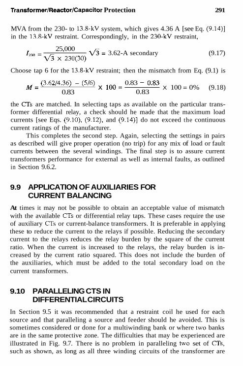
TransformerlReactorlCapacitor Protection 291
MVA from the 230- to 13.8-kV system, which gives 4.36 A [see Eq. (9.14)] in the 13.8-kV restraint. Correspondingly, in the 230-kV restraint,
fi = 3.62-A secondary 25,000
6 X 230(30) I230 = (9.17)
Choose tap 6 for the 13.8-kV restraint; then the mismatch from Eq. (9.1) is
(3.6214.36) - (516) 0.83 - OX3 0.83
x loo= X 100 = 0% (9.18) M = 0.83
the CTs are matched. In selecting taps as available on the particular trans- former differential relay, a check should he made that the maximum load currents [see Eqs. (9.10), (9.12), and (9.14)] do not exceed the continuous current ratings of the manufacturer.
This completes the second step. Again, selecting the settings in pairs as described will give proper operation (no trip) for any mix of load or fault currents between the several windings. The final step is to assure current transformers performance for external as well as internal faults, as outlined in Section 9.6.2.
9.9 APPLICATION OF AUXILIARIES FOR CURRENT BALANCING
At times it may not be possible to obtain an acceptable value of mismatch with the available CTs or differential relay taps. These cases require the use of auxiliary CTs or current-balance transformers. It is preferable in applying these to reduce the current to the relays if possible. Reducing the secondary current to the relays reduces the relay burden by the square of the current ratio. When the current is increased to the relays, the relay burden is in- creased by the current ratio squared. This does not include the burden of the auxiliaries, which must be added to the total secondary load on the current transformers.
9.10 PARALLELING CTS IN DIFFERENTIAL CIRCUITS
In Section 9.5 it was recommended that a restraint coil he used for each source and that paralleling a source and feeder should he avoided. This is sometimes considered or done for a multiwinding bank or where two banks are in the same protective zone. The difficulties that may be experienced are illustrated in Fig. 9.7. There is no problem in paralleling two set of CTs, such as shown, as long as all three winding circuits of the transformer are

292
Ia' Breaker Open
Chapter 9
"' "
FIGURE 9.7 Potential loss of restraint that may result by paralleling circuits in differential protection: (a) no restraint; (b) full restraint ( S , source of fault current; F, feeder-no significant fault source).
in service. However, with lhe possibility of emergency operation during which lhe left-hand hreaker is open, restraint is lost and lhe differential relays operate essentially as sensitive overcurrent units. As shown in Fig. 9.7a, current flow from the right-hand source to the feeder should net zero. This is difficult with different CTs and voltage levels. Even with a perfect match, the difference in lhe CT exciting currents will flow to lhe differential relay, as explained in Chapter 6. In other words, ihere is no effective restraint for this condition. This connection might be marginally safe for normal-load flow, but is quite subject to misoperation for external faults out on the feeder.
Paralleling lhe CTs may he done if lhe transformer would never be operated with lhe left-hand breaker open. I1 is not recommended, as there is always the possibility that during an unusual emergency situation, operators may resort to unplanned opening of the left-hand breaker. In contrast, with the recommended restraint for each circuit (see Fig. 9.7b), full restraint ex- ists, as shown.
Feeder circuit CTs may be paralleled in a differential scheme as long as there is negligible fault current supplied through them. Caution should be exercised, recognizing that for external faults out on one of lhe feeders, some of the secondary current required for balancing the differential is di-

TransforrnerIReactorlCapacitor Protection 293
1
A R A R V V
FIGURE 9.8 transiormers.
Single-line differential connections for multiple connections to
verted to magnetize lhe other feeder CTs that are not supplying primary current. This is discussed in Chapter 5.
Typical examples of transformers with multiple circuits are illustrated in Fig. 9.8. As recommended and shown, each circuit should be connected to an individual restraint winding in the differential relay, following lhe procedure outlined earlier. Paralleling of circuits and CTs should be avoided, but when necessary, the problems discussed should be considered carefully and documented to the operating personnel.
9.1 1 SPECIAL CONNECTIONS FOR TRANSFORMER DIFFERENTIAL RELAYS
Occasionally, it may be necessary to use star-connected CTs on a grounded- wye circuit in a differential scheme instead of lhe preferred delta CT con- nection. This can occur in applications for which a differential zone is es- tablished around severa1 banks. For these, the first consideration is the possibility of a sympathetic inrush. The zone should be examined to see if there is any possible operating condition during which one bank can be energized, followed by energizing a second bank. If all banks in lhe protec- tion zone are always energized together, sympathetic inrush will not occur, and a single differential relay application is possible. Most of these cases

294 Chapter 9
are the result of the omission of circuit breaker(s) and associated CTs for cost saving, but at the expense of less flexible system operation.
Figure 9.9 shows the connection of a zero-sequence trap to divert the zero-sequence current from the differential relay with wye-connected CTs on the grounded side of the transformer. It is essential in these types of connections (for any connections) that a path exists for zero-sequence cur- rent flowing into or out of a hank in the CT secondaries. This is provided by the trap, as shown. If a proper path is not available in the CT secondaries, the equivalent of an open secondary circuit exists, with resulting saturation
Transformer
FIGURE 9.9 Special differential connections using star-connected CTs on the transformer grounded-wye terminals.

TransformerIReactorlCapacitor Protection 295
and high and dangerous voltages. This true for positive and negative as well as zero sequences; the absence of a proper path for zero sequence would be apparent only on the occurrence of a ground fault in the othenvise-balanced system.
The zero-sequence trap consists of three auxiliary CTs. Their ratio is not important as long as they are the same. Note that the operating coil neutral is nor connected to the CT neutral or grounded. It is not necessary for a zero-sequence current flow for correct relay operation. Connecting this operating coil neutral to the CT neutral places the restraint and operating coil windings in parallel with the primary winding of the trap. This could cause enough diversion of current for an external ground fault and relay misoperation.
With the left-hand CTs connected in wye (see Fig. 9.9), it is necessary to connect the right-hand CTs in delta properly to provide currents in phase through the differential relay for external primary current flow. This phasing should be done as in the foregoing, starting with balanced I,, I,,, and I , currents into (or out of, if preferred) the wye transformer windings. Carrying this through it can be seen with a phasor diagram that (Ia-L) ~ (Ih- l0) is i n phase with I., and similarly for the other phases. The per unit magnitudes are three times larger, but this can be adjusted by the CI and relay taps. Ground faults within this differential zone will operate the relays through the positive and negative fault current components (see Fig. 9.9).
9.12 DIFFERENTIAL PROTECTION FOR THREE-PHASE BANKS OF SINGLE-PHASE TRANSFORMER UNITS
Single-phase transformer units are connected in various three-phase config- urations, usually wye-delta and with associated circuit breaker(s) and CTs, as illustrated in Fig. 9.5. If it becomes necessary or desirable to use the CTs on the transformer bushings, the normal differential connection cannot be used when the CTs are inside the delta, as in Fig. 9.10. Two sets of CTs connected in parallel are required to provide protection for ground faults in these windings.
Star-connected CTs can be used on both sides. The phasor currents in Fig. 9.10 show the balance for symmetrical currents flowing through the bank. There is a 2:l ratio difference (per unit) of the CTs on the two sides. This can be adjusted by CT or relay taps, or a combination of both. Because each transformer is an individual unit, there will be no possibility of a phan- tom tertiary effect to plague the differential operation.
For three-phase banks, for which the three windings and interconnec- tions are all inside the common tank, the standard differential connections

296 Chapter 9
L
1 . Left-hand per unit CT ratio ahoxn two times the riqht-hand unit per unit CT ratio.
FIGURE 9.10 Differential relay connections for the protection of three single- phase transformers connected delta-wye using CTs in t he transformer bushings.
of Figs. 9.5, 9.6, 9.8, or 9.9 can be used with CTs located as shown or with CTs in the three-phase transformer bushings on either side.
9.13 GROUND (ZERO-SEQUENCE) DIFFERENTIAL PROTECTION FOR TRANSFORMERS
The ground differential scheme provides compromise protection for delta- wye-grounded transformer banks. It is useful when there are no available or

Transforrner/Reactor/Capacitor Protection 297
convenient CTs on the delta side. This is common for distribution and in- dustrial ties with the delta as the high-voltage side and, possibly, protected by fuses.
This scheme protects only the wye-grounded windings and associated circuits, and only for ground faults, the most likely and wmmon fault. A typical application is shown in Fig. 9.11 using a conventional differential relay. The differential zone includes the circuits between the two sets of CTs. The delta blocks operation for faults in that area. The techniques of “phasing” and “ratioing” are as outlined previously, except one uses only zero-sequence current flow to an external fault. These currents are shown in Fig. 9.11. The time-overcurrent relay 51N, shown connected to a separate CT, is recommended for all grounded transformers. It is a “last resort” ground-fault protection and must be set to coordinate with relays it over-
n C
Differential
- I - c
Zero Sequence Current Flow for External Ground Fault.
FIGURE 9.1 1 Ground (zero-sequence) differential protection for delta- grounded-ye transformer bank using a conventional differential relay.

298 Chapter 9
reaches. This is discussed in more detail later. It may be connected in the differential circuit, which adds burden to the differential circuit and can affect operation.
If the delta side is protected by fuses, ground faults in the differential zone may not provide sufficient current to clear the faults adequately from the delta-side source. As indicated previously, a 1-pu phase-to-ground fault on the wye side appears as a 0.577-pu phase-to-phase fault on the delta side (see also Fig. 9.20). This adds to the difficulty of detection. Any fault- limiting by neutral impedance or fault resistance further reduces the fault magnitudes. Thus, it frequently becomes impossible to clear ground faults by the high-side fuses. Accordingly, the ground differential is useful for the ground faults in its zone. The problem is to clear the fault from the delta- side source without a local breaker, and if the nearest breaker is at a remote station.
9.14
Without a fault-interrupting device available at the transformer primary ter- minals, there are several possibilities for tripping remote breaker(s) as nec- essary to clear faults. All these methods are in practical use.
EQUIPMENT FOR TRANSFER TRIP SYSTEMS
9.14.1 Fault Switch
A spring-loaded fault switch is connected to the delta-supply side. The trans- former protection relays operate to release the switch and thus fault the source system. Protective relays at the remote breaker(s) sense this fault and operate to clear it, thereby removing the source(s).
Most commonly, this is a single switch that applies a solid single-line- to-ground fault to operate the remote ground relays. Often, these remote relays can operate instantaneously to provide rapid isolation. There are a few installations of a three-phase-to-ground switch that applies a solid three- phase fault. The advantage is high redundancy; one or two switches can fail and still result in clearing the fault. Also, normally, the phase and, with one ground switch failure, the ground relays at the remote location(s) can clear the fault. The disadvantage is higher cost, increased maintenance, and ap- plying a higher-current three-phase fault on the system. This grounding- switch technique is quite practical and relatively simple. However, some shudder at putting any deliberate fault on the system.
9.14.2 Communication Channel
The transformer protective relays initiate a tripping signal that is transmitted over a transfer trip channel to operate remote breaker(s). This channel may

TransforrnerIReactorlCapacitor Protection 299
be by power-line carrier (radio frequency over the power lines), audio tones over a telephone circuit or microwave channel, or a direct-wire fiber-optic pilot pair. High security is very important to avoid undesired trip operation from extraneous signals on the channel. This and the usually higher cost are the major disadvantages. It is most important that these equipment transfer trip systems be carefully and thoroughly engineered. It is not possible to enhance their security with fault detectors at the breaker-tripping terminal(s), because the low-side faults generally will be at too low a level.
9.14.3 Limited Fault Interruption Device
A circuit switcher or breaker with limited fault interrupting capability is installed at the transformer on the delta-source side. The transformer pro- tective relays initiate the tripping of this device directly or with a slight time delay. The scheme is based on the good probability that the remote relays will operate and clear any high-current fault at high speed and before the circuit switcher or breaker can open. If the remote relays do not sense the fault or they operate slowly, the level of fault current is within the inter- rupting capabilities of the local device.
9.15 MECHANICAL FAULT DETECTION FOR TRANSFORMERS
The accumulation of gas or changes in pressure inside the transformer tank are good indicators of internal faults or trouble. These devices are recom- mended, wherever they can be applied, as excellent supplementary protec- tion. They are frequently more sensitive, so will operate on light internal faults that are not detected by differential or other relays. However, it is important to recognize that their operation is limited to problems inside the transformer tank. They will not operate for faults in the transformer bushings or the connections to the external a s . Thus, their protective zone is only within the tank, in contrast with the differential protective zone of Fig. 9.5.
9.15.1 Gas Detection
Gas detection devices can be applied only to transformer units built with conservator tanks. This type of transformer is common in Europe, but is not widely used in the United States. For these units with no gas space inside the transformer tank, a gas accumulator device commonly known as the Buchholz relay is connected between the main and conservator tanks. It collects any gas rising through the oil. One part of the relay accumulates gas over a time period to provide sensitive indication of low-energy arcs. It is used generally to alarm, for gas may be generated by tolerable operating

300 Chapter 9
conditions. The other part responds to heavy faults, forcing the relay open at high velocity. This is used to trip in parallel with the other transformer protection.
9.15.2 Sudden Pressure
Sudden pressure devices are applicable to oil-immersed transformers. One type operates on sudden changes in the gas above the oil, another on sudden changes in the oil itself. Both have equalizing means for slow changes in pressure, which occur with loading and temperature changes. They are sen- sitive to both low- and high-energy arcs within the transformer and have inverse-time characteristics: fast for heavy faults and slower for light faults. Generally, they are used to trip with the contacts in parallel with the differ- ential and other relay trip contacts, although they can he used for alarm if preferred.
9.16 GROUNDING TRANSFORMER PROTECTION
To provide system grounding on the delta side of power system transformer hanks, a shunt-connected grounded wye-delta or zigzag transformer hank is applied. With wye-delta units, the delta operates as an unloaded tertiary to circulate zero-sequence current. If this tertiary has a CT available inside the delta, it can be connected to a time-overcurrent 51N relay. This relay receives Zo for ground faults out on the system, so it must be coordinated with other ground relays.
The ground differential protection (see Fig 9.11), is applicable to the grounded wye-delta units, and as shown in Fig. 9.12 for zigzag units. An alternative is to use three-phase time-overcurrent 51 relays, each connected to one of the line-side CTs. Because load does not pass through these units, the CT ratios and relay taps can be based on ground-fault current.
The zigzag bank essentially consists of three 1:l ratio transformers interconnected (see Fig. 9.12). The zero-sequence current flow is illustrated. Positive- and negative-sequence currents cannot flow, for they are 120" out of phase.
Sudden pressure- or gas-actuated trip relays are highly recommended where applicable for light internal fault protection. Turn-to-turn faults are always difficult to detect. In a zigzag unit, they can be limited by the mag- netizing impedance of an unfaulted phase.
Grounding transformers frequently are directly connected to the bus or associated power transformer without a fault-interruption device. A typical example would be to connect the grounding unit between the power trans-

TransformerIReactorlCapacitor Protection
- 1 * I - B
It l t c
301
FIGURE 9.12 Ground (zero-sequence) differential protection for a zigzag transformer bank using a conventional differential relay.
former delta and the right-hand circuit breaker in Fig. 9.9. This application requires the use of a zero-sequence trap, as shown, because there is a zero- sequence source now on both sides of the wye-delta bank, with a 30" shift across the hank.
With the grounding bank within the transformer differential zone, as indicated, an alternative connection to Fig. 9.9 would be to connect the right- hand CTs in wye with a zero-sequence trap, and the left-hand CIS in delta.
A set of auxiliary a s could he used instead of the zero-sequence trap to provide the necessary zero-sequence isolation and the 30" shift. The trap is preferred, because it is involved only during ground faults. Several ar- rangements are possible. In working these out, do not connect the main CTs in wye and to the delta-connected auxiliary, for there will be no zero- sequence path for primary fault currents.

302 Chapter 9
9.17 GROUND DIFFERENTIAL PROTECTION WITH DIRECTIONAL RELAYS
If the C I ratios or characteristics are not suitable for the application of conventional differential relays, a directional overcurrent relay, differentially connected, can be used. This is particularly applicable where ground-fault current is limited by neutral impedance 01 where a low neutral CT is used for higher sensitivity for remnte faults on distribution feeders.
Two applications are shown. Figures 9.13 and 9.14 use an auxiliary current-balancing autotransformer. Figures 9.15 and 9.16 use an auxiliary
(a)
FIGURE 9.13 Ground (zero-sequence) differential protection for a delta- grounded-wye transformer bank using a directional overcurrent relay with current-balancing autotransformer. The currents shown are for external faults: (a) Zero-sequence current flow for external ground faults; (b) example of zero-sequence current flow for an external ground fault (directional sensing relay does not operate).


304 Chapter 9
inverse-time characteristics, operating very fast for large-current internal faults.
The directional overcurrent relay has a separate directional unit that operates as the product unit. The overcurrent unit of the relay is nondirec- tional and operates on the magnitude of current in its main coil. In the figures, it is the coil without polarity and connected basically across the CIS. Again it has inverse-time characteristics, operating fast for high current, but only if the directional unit has operated. It is torque-controlled.
~ e l t a Connected
(a)
FIGURE 9.14 Operation of the differential system of Fig. 9.13 for internal faults: (a) Zero-sequence current flow for internal ground faults; (b) example of zero-sequence current flow for a n internal ground fault, with no current from line (currents in amperes); (c) example of zero-sequence current flow for an internal ground fault, with current from line (currents in amperes).

TransformerIReactorlCapacitor Protection 305
RCN=40 - 310N=400
310
1
Equivalent of 3 CTB RCL = 400
( C )
FIGURE 9.14 Continued
5 . 7 5

306 Chapter 9
The auxiliary transformers are required to provide correct differential operation: not to operate for external faults outside the differential zone, but to operate for the ground faults inside the differential zone. These schemes operate when no ground current is supplied from the system to the internal faults. This would be common for many distribution and industrial appli- cations. With no current, as in Figs. 9.14b and 9.16b, it must be recognized that some of the neutral secondary current will be diverted to excite the auxiliaries and line CTs, as discussed in Chapter 5. This should be small with good-quality (JTs and is neglected in the figures.
If ground current is always supplied from the system for internal faults, the product relay could be applied with one coil connected across the line
Delta Connected
a b c
(a)
FIGURE 9.15 Ground (zero-sequence) differential protection for a delta- grounded-wye transformer bank using a directional overcurrent relay with auxiliary CT (currents shown are for external faults): (a) Zero-sequence cur- rent flow for external ground fault; (b) example of zero-sequence current flow for an external ground fault directional (currents in amperes).
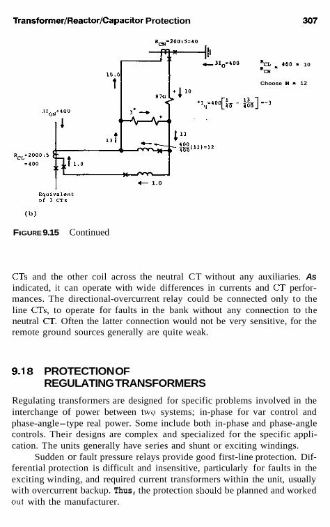
TransformerIReactorlCapacitor Protection 307
RcN-200:5=10
".. * 400 - 10 %ti
Choose N - 12
t 1.0 I Equivalent of 1 C T 5
(b)
FIGURE 9.15 Continued
CTs and the other coil across the neutral CT without any auxiliaries. As indicated, it can operate with wide differences in currents and CI perfor- mances. The directional-overcurrent relay could be connected only to the line CTs, to operate for faults in the bank without any connection to the neutral CT. Often the latter connection would not be very sensitive, for the remote ground sources generally are quite weak.
9.1 8 PROTECTION OF REGULATING TRANSFORMERS
Regulating transformers are designed for specific problems involved in the interchange of power between two systems; in-phase for var control and phase-angle-type real power. Some include both in-phase and phase-angle controls. Their designs are complex and specialized for the specific appli- cation. The units generally have series and shunt or exciting windings.
Sudden or fault pressure relays provide good first-line protection. Dif- ferential protection is difficult and insensitive, particularly for faults in the exciting winding, and required current transformers within the unit, usually with overcurrent backup. Thus, the protection should be planned and worked out with the manufacturer.

308 Chapter 9
9.1 9 TRANSFORMER OVERCURRENT PROTECTION Phase- or ground-fault overcurrent protection is common for transformers. This is either as the primary protection for smaller units or for any unit without differential protection, or as backup protection on larger units pro- tected by differential relays. At about 10 MVA and below, primary fuses may be used. Otherwise, inverse-time-overcurrent relays and, at higher volt- ages, distance relays provide protection for the transformer and associated circuits. Because these devices can operate well outside the transformer pro- tection zone, their application and setting is a combination of transformer and associated system protection. The emphasis here is on transformer pro- tection and the subject will be expanded later in connection with the pro- tection of other equipment, primarily feeder and line protection.
Delta Connected
".. %N - 3101 R CL
"I11
(a)
FIGURE 9.16 Operation of the differential system of Fig. 9.15: (a) Zero- sequence current flow for internal ground faults; (b) example of zero- sequence Current flow for an internal ground fault, with no current from line (currents in amperes); (c) example of zero-sequence current flow for an in- ternal ground faull with current from line (current in amperes).

1 +
87G
310L=0 4 1 Av hV
+
c 10
O -
N=12
I =" + E!,l3) q 4 0 400
c =16.5
3IOL=200
I 6 . 5
Y
-x- - 3IoN=4O0
+ 4'0 <>
I ,
I 4 6 6 . 5
1 c
t R =400 I CL
.,- - 0 . 5
309
Eq"i"a1e"L of 3 C T s
( C )
FIGURE 9.16 Continued

310 Chapter 9
It is desirable to set the protective devices as sensitive as possible, hut the fuses and phase-overcurrent relays must not operate on any tolerable condition, such as magnetizing inrush; the maximum short-time overloads, such as may occur when reenergizing circuits after an outage (cold-load pickup); or any emergency-operating condition. The ground relays must be set above the maximum zero-sequence unbalance that can exist principally as the result of single-phase loading.
Instantaneous overcurrent-relays may be applied to supplemental dif- ferential or overcurrent protection and provide protection for heavy primary transformer faults. They must he set not to operate on magnetizing inrush (unless a harmonic restraint is used), on the maximum short-time load (wld- load), or on the maximum secondary three-phase fault. A typical setting would be 150-200% of the greatest of these currents. This may limit their operation on primary faults.
On the other hand, the relays or fuses should protect the transformers against damage from through faults. High fault current passing through the transformer can cause thermal as well as mechanical damage. High temper- atures can accelerate insulation deterioration. The physical forces from high currents can cause insulation compression, insulation wear, and friction- induced displacement in the windings. ANSIiIEEE define the limits for these faults.
9.20 TRANSFORMER OVERLOAD-THROUGH- FAULT-WITHSTAND STANDARDS
The ANSInEEE standards for distribution and power transformers specify- ing their overload-through-fault capabilities were changed in about 1977 (see IEEE (37.12 and the article by Griffin in the Bibliography). Comparison of the change is given in Table 9.1. The multiples of rated current represent the maximum possible and are derived assuming an infinite source (zero impedance). Thus, the maximum symmetrical fault through the transformer bank with 4% impedance would be 1/0.04 = 25 pu or 25 times the bank- rated current, as shown.
The source impedance is never zero, but it can be very small relative to the transformer bank impedance, particularly for an industrial plant or small distribution substation connected to a large utility power system. Hence, the multiples represent a maximum limit.
Soon after this change to all 2-s limits, protection engineers discovered that they had been using a thermal overload curve (Fig. 9.17a), published in ANSI Standard C37.91, Guide for Protective Relay Applications to Power

Transformer/Reactor/Capacitor Protection 31 1
TABLE 9.1 Modified in 1982"
ANSVIEEE Transformer Overcurrent Capability Standards Until
Transformer Multiples of impedance rated current (% of rated kVA)
25 4 20 5 16 6 14 or less 8 or greater
Maximum current withstand (s)
1977 (1980) 1973
2 2 2 3 2 4 2 5
"ANSI/IEEE C57.12.00. Old Standard dated 1973, approved 1977, but not officially published until 1980.
Transformers, for overcurrent transformer protection, and that the new 2-s standard would severely limit power transformer protection for through faults. This dilemma has led to further changes, which were approved late in 1982 and are summarized in Table 9.2 and Fig. 9.17. These changes are incorporated in the several applicable standards. The conflict existed because C37.91 was a thermal damage curve, whereas '257.12.00 was concerned primarily with mechanical damage from the through faults. The latest changes (see Fig. 9.17) cover both thermal and mechanical limits.
The new standard has six curves; one each for categories I and IV, and two each for categories I1 and 111. The basic curve shown by the solid line in Fig. 9.17 for all categories is the same and, as such, applies to all 4% impedance transformers. These can withstand through currents of 25 times normal base current for 2 s. Modifying curves (shown as dashed lines) apply for transformers with other than 4% impedance, depending on the fault frequency over the entire life of the unit.
The frequency of faults that might occur during the entire life of a transformer is an estimation based on past experience and judgment. Aguide to aid in this determination is outlined in Fig. 9.18. In cases of doubt, the frequent-fault curves should he used.
The application of transformer protection to meet this standard can be outlined as follows: For a given transformer
1. 2.
3.
Determine the category from Table 9.2. If category I1 or 111, determine whether the service is subject to frequent or infrequent faults (see.Fig. 9.18). Select the appropriate curve from Fig. 9.17 (or the ANSI standard).

31 2 Chapter 9
1 TIMES NOFWAL BASE CURRENT ( 8 )
FIGURE 9.17 Through-fault protection curves for transformers: (a) Far cate- gory I frequent or infrequent faults and for infrequent faults with categories I J and 111; (b) for frequent faults with category II transformers; (c) for frequent faults category 111 and frequent or infrequent category IV transformers.

TransformerIReactorlCapacitor Protection
USE CATEGORY I CURVE ABOVE 50 SEC
RHER
3 5 10 1520 30
I TIMES N0-L BASE CURRENT
(b)
USE CATEGORY I CURVE ABOVE 100 SEC
200
100
5 0 40 30
z
w m
8 20
z 10 w e
E 5 r
4 * 3
2
1
I I TIMES N O W L BASE CURRENT
TRANSFORMER \ z
( C )
FIGURE 9.17 Continued
313

I
TABLE 9.2 ANSlil EEE Transformer Overload-Through-Fault Standard Categories
Transformer ratings (kVA) Use curve Frequent
Cateoorv Sinole-ohase Three-ohase (Fia. 9.17) faults" Dotted cutves amlv fromb
5-500 15-500 a 1250f 1250 25-501, where t = - - -
601' - I' ~~
at 60 Hz.
fault where IZt = K; K is determined at maximum I where t = 2.
fault where 12t = K; K is determined at maximum I where t = 2.
I1 501 -1,667 501 -5,000 a o r a + b 10 70-100% of maximum possible
111 1,668-10,000 5,001 -30,000 a o r a + c 5 50-100% of maximum possible
IV Above 10 MVA Above 30 MVA a + c - Same as category 111.
"Faults that occur frequently are typically more than the number shown and are for the lifetime of the transformer, Infrequent faults are less than that shown for the life of the transformer. Category II and Ill infrequent-fault curve (see Fig. 9.17a) may be used for backup protection when the transformer is exposed to frequent faults, but is protected by high-speed primary relays. ' I , symmetrical Sholt-circuit current in per unit of normal base current using minimum nameplate kVA; f , time in seconds: f, frequency in hertz. Per unit currents of 3.5 or less probably result from overloads. in which case the transformer-loading guides should be followed. 0
5 B z (D

SLE

316 Chapter 9
9.21 EXAMPLES: TRANSFORMER OVERCURRENT PROTECTION
The several examples are from IEEE C37.91, Guide for Protective Relay Applicatiom to Power Transformers. These are sound typical applications.
9.21.1 An Industrial Plant or Similar Facility Served by a 2500-kVA 12-kV:480-VTransformer with 5.75% Impedance
The protection consists of power fuses on the primary and low-voltage di- rect-acting circuit breakers with series overcurrent trip units on the secondary side and associated feeders. From Table 9.2, this transformer is category 11, and with metal-clad or metal-enclosed secondary switchgear, the fault fre- quency can be considered infrequent. Thus Fig. 9.17a applies.
This curve is replotted on Fig. 9.19, where the abscissa is secondary amperes. This translation is
2500
~ X 0.48 = 3007 A at 480 V (9.19) ~ p r u n 7 c = Ir%d =
and so for various times:
Time (s) Per unit I from Fig. 9.17a
1000 2.3 300 3.0 100 4.0 50 5.0 12.5 10.0
from Fig. 9.17a
4.13 17.39
Equivalent I amperes at 480 V (pu X
30007)
6,916 9,021
12,028 15,035
52.296 30,070
For 50 s and less,
- 50 s such as ~ - 1250 1250 t = -
I’ 5 2
as shown. The maximum possible current with an infinite source is
(9.20)
= 17.39 pu 1 I = - - - - -
0.0575 (9.21)

TransformerlReactorlCapacitor Protection 317
secondary current in limperes at 480 volts 4
FIGURE 9.19 infrequent-fault secondary system.
Overcurrent protection for a category I I transformer serving an
where
(9.22)
so this is the termination of the transformer through-fault protection curve.

31 8 Chapter 9
On the primary side, rated current is
2500 = 120.3 A at 12 kV v5 x 12
lpr"ni, = IC%d = (9.23)
To avoid operation on magnetizing inrush, short-time transient load, and so on, yet provide protection for secondary faults, typical fuse ratings are se- lected at about 150% of rated current. Thus 1.5 X 120.3 = 180.4 A, so 200-A fuses were selected and their time characteristics plotted. Both total clearing and minimum melt curves are shown. Since the current magnitudes in the primary are only 57.7% of the secondary current for phase-to-ground faults, the fuse curves are moved to the right by multiplying all values by 1.73 (d) in addition to the transformer-winding ratio (see Fig. 9.19). The three-phase fault magnitudes are the same in per unit (Fig. 9.20). The fuse curves extend to higher currents, as these are possible for high-side faults (in primary amperes) between the fuses and the transformer.
The transformer secondary and the feeders have low-voltage circuit breakers with direct-acting overcurrent units. These have long-time and short-time-instantaneous elements. The characteristics are a band between the total clearing times and the reset times (see Fig. 9.19). For this example, the transformer breaker long-time unit is set to pick up at 1.21r,,,,, = 1.2 X
3007 = 3608 A at 480 V, where the time is The short-time pickup is set at 2.51,,,,,, or 2.5 X 3007 = 7518 A at 480 V. A time delay of 0.35 s is used to provide coordination with the feeders. The feeder circuit breakers are set with the long-time unit at 1.2 X = 1.2 X 800 = 960 A and the short-time set instantaneously (0.05 s) at 6 times 800, or 4800 A at 480 V. Chapter 12 gives more details on these setting criteria.
The protection plot of Fig. 9.19 shows good protection and coordi- nation except for light secondary faults. The primary fuse curves cross the transformer through the fault protection curve at about 13,000 A for three- phase faults at about 23,000 A for phase-to-ground faults. This means that the transformer is not protected according to the standard for faults of these magnitudes-or less-hy the fuses. Such faults are possible. If they are in the transformer, damage has already occurred and must become heavier he- fore the source can be removed by the fuses. If between the transformer and the secondary circuit breaker, it must also develop to a heavier fault, which means more damage and time; however, the probability of faults in this area will usually be small.
Typical industry data indicate that, at 480 V, arcing phase-to-ground faults may he as low as 19% of the rated fault value. Thus, for a secondary fault maximum of 52,296 A, the primary current for the fuses would be 52,296 X 0.19 X 0.577 X 0.48112 = 229 A at 12 kV, just above the

Transformer/Reactor/Capacitor Protection 319
Ibl
A;h
4 1.0 B
c .50 C I
0
I 0
ICI
4 . 5 7 7
B A3 C c . 5 7 7
FIGURE 9.20 Review of faults through delta-wye transformer banks (currents shown in per unit): (a) Three-phase faults; (b) phase-to-phase faults; ( c ) phase-to-ground faults where X, = X, = X,.
ZOO-A rating, and it is doubtful that the fuses will give any protection until severe burning increases the fault current.
Secondary faults on the bus should he cleared by the secondary trans- former circuit breaker, and faults on the feeders by their circuit breakers backed up by the transformer breaker. Thus, the primary fuses are backup for these faults if they can “see” these secondary faults.
The frequent fault curve modification from Fig. 9.1% bas been shown in Fig. 9.19 for comparison. As can he observed, the primary fuse protection for through faults or secondary phase-to-ground faults is very marginal.

320 Chapter 9
9.21.2 A Distribution or Similar Facility Served by a 75OO-kVA, 115:12-kVTransformer with 7.8% Impedance
The primary protection is power fuses. A transformer secondary breaker is not used, and the feeders have circuit reclosers.
This transformer is category I11 and the secondary is subject to frequent faults. Similar to the example in Section 9.21.1, the transformer through- fault protection curve is translated from Fig. 9.17a and c to secondary am- peres for Fig. 9.21.
7500 = 360.84 A at 12 kV (9.24) 4 x 12 IF,-> = I,,,,, =
The maximum secondary fault, assuming that the source is very large rela- tive to the transformer, and thus is infinite (X = 0), is
1 0.078
13& = I,+<, = ~ - - 12.82 pu = 4626 A at 12 kV (9.25)
Points on the transformer through-protection curve are:
Equivalent I Time ( s ) Per unit I ampercs at 12 kV from Fig. 9.17a.c from Fig. 9.17a,c (pu X 360.84)
1000 300 100 50 30.42
8 3.29 2
2.3 3.0 4.0 5.0" 6.41" 6.4lh
12.8Zh 1 Oh
830 1082.5 1443.4 1804.2 2313 2313 3608.4 4626
'For infrequent fault incident, K = 1250 from 5.0 to 12.82 pu; for frequent fault incidcnt, K = 1250 from 5.0 to 6.41 pu. 'For frequcnt fault incident, K = 328.73 from 6.41 to 12.82 pu.
On the primary side.
7500 6 X 115
= 37.65 A at 115 kV (9.26) Isru";c = ICdlCd =
and 65E-A fuses were used (1.73 X 37.65). Their characteristics are plotted
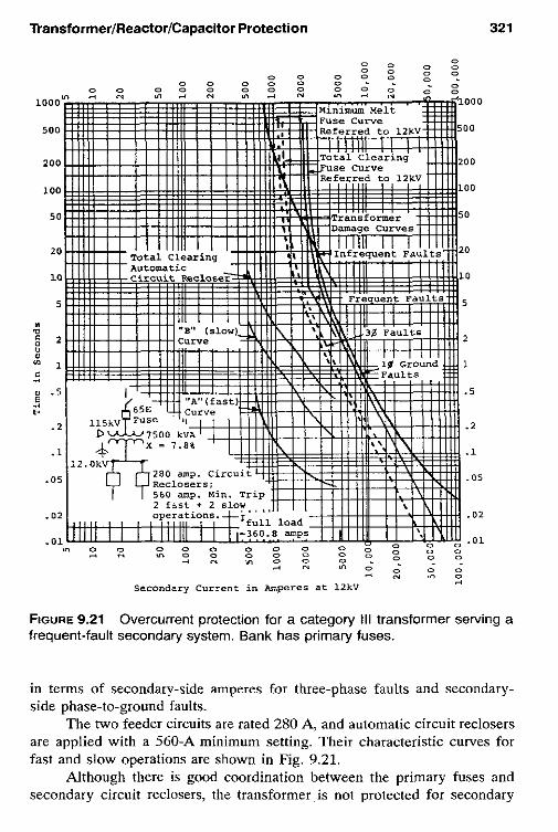

322 Chapter 9
phase-to-ground faults with the frequent-fault curve. Also, with the infrequent-fault curve, there is inadequate protection for ground faults of about 3000 A and less. Again the phase shift through the bank provides 57.7% less ground-fault current (see Fig. 9.20).
For faults out on the feeders, the primary-side fuses serve as backup, so they should seldom be called on to operate. However, the fuses are primary protection for faults on the secondary side, up to the circuit reclos- ers. It is hoped that these ground faults will be infrequent and greater than 3000 A to avoid potential damage to the transformer. These are risks that must be evaluated by the power system personnel.
9.21.3 A Substation SeNed by a 12/16/20-MVA 115: 12.5-kV Transformer with 10% Impedance
The primary has a relayed breaker, but without a transformer secondary breaker. This is category III transformer, so that the curves of Fig. 9.17a and c apply, which are replotted on Fig. 9.22, using secondary amperes. The maximum fault current with an infinite source (X = 0) is
I>+ = I<,<; = - = 10 pu = 5542.6 A at 12.5 kV 1 .o 0.1
(9.27)
where
12,000 = 554.26 A at 12.5 kV (9.28)
X 12.5 I V d = fr*cd =
K in Table 9.2 is 1250 for infrequent faults from 5.0 pu to the maximum of 10 pu. and K = 200 for infrequent faults over the same range.
The transformer has three MVA ratings: the first is a self-cooled rating; the second a rating with forced oil, and the third a rating with both forced oil and air. Thus, the maximum load is
20’ooo 4 X 115
= 100.4 A at 115 kV (9.29)
and 1005 (20:l) primary CTs are selected. Inverse-time-overcurrent phase relays (51) are set on tap 8, so pickup on 8 X 20 = 160 primary amperes, equivalent to 1472-A secondary amperes. Their pickup for secondary phase- to-ground faults is 1472/0.577 = 2551 A. The relay-operating curves are plotted on Fig. 9.22 for specified time dials.
The 12.5-kV feeders are 6000 kVA with 3005 (60:l) CTs, relay pickup phase 480 secondary amperes (Sl), 240 secondary amperes ground (5113). These curves are plotted in Fig. 9.22 for specified time dials.


324 Chapter 9
9.22 TRANSFORMER THERMAL PROTECTION
Thermal protection is usually supplied as a part of the transformer. Gener- ally, it is used for monitoring and alarm, but may he used for tripping. Various types of thermal indicators are used to detect overheating of the oil, tank, tank terminals, failures of the cooling system if used, hot spots, and so on. These devices may initiate forced-cooling equipment. This protection is beyond the scope of this book.
9.23 OVERVOLTAGE ON TRANSFORMERS
Transformers must not be subject to prolonged overvoltage. For maximum efficiency they are operated near the knee of their saturation curve, so at voltages above about 110% of rated, the exciting current becomes very high. Just a few percent increase in voltage results in a very large increase in current. These large currents can destroy the unit if not reduced promptly.
Protection against overvoltage is seldom applied directly, but is in- cluded in the regulating and control devices for the power system. An ex- ception exists for unit generator-transformers, for which overvoltage of these units is more likely to occur as they are brought onto or removed from service. This protection is discussed in Chapter 8.
9.24 SUMMARY. TYPICAL PROTECTION FOR TRANSFORMERS
The protection recommended and commonly applied for transformers is summarized in the following figures. The application for the various devices has been discussed in previous sections. It should be noted and recognized that these are general recommendations. More or less protection may be applied for any specific situation and will depend on local circumstances and individual preferences.
9.24.1 Individual Transformer Units
Figure 9.23 summarizes the protection for banks where fuses are used on the primary. For larger or important banks in this category, differential pro- tection may be applied overall by using CTs in the transformer primary bushings, or a ground differential, as discussed in Section 9.13. Both require primary source tripping as discussed in Section 9.14.
For transformer banks with primary breakers, the protection is sum- marized in Fig. 9.24. Relay 51G provides backup protection for secondary bus and feeder faults and must he time-coordinated, with other ground relays protecting the various feeder circuits on the secondary bus. Similarly, phase
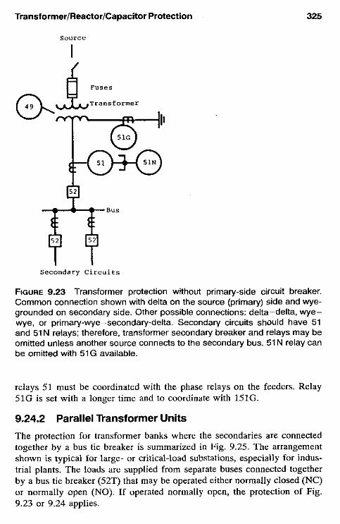
Transformer/Reactor/Capacitor Protection
S0"rCe
I
Transformer
325
Secondary C i r c u i t s
FIGURE 9.23 Transformer protection without primary-side circuit breaker. Common connection shown with delta on the source (primary) Side and wye- grounded on secondary side. Other possible connections: delta-delta, wye- wye, or primary-wye-secondary-delta. Secondary circuits should have 51 and 51 N relays; therefore. transformer secondary breaker and relays may be omitted unless another source connects to the secondary bus. 51N relay can be ornitted with 51G available.
relays 51 must be coordinated with the phase relays on the feeders. Relay 51G is set with a longer time and to coordinate with 151G.
9.24.2 Parallel Trançformer Units
The protection for transformer banks where the secondaries are connected together by a bus tie breaker is summarized in Fig. 9.25. The arrangement shown is typical for large- or critical-load substations, especially for indus- trial plants. The loads are supplied from separate buses connected togetber by a bus tie breaker (529 that may be operated either normally closed (NC) 01 normally open (NO). If operated normally open, the protection of Fig. 9.23 or 9.24 applies.

326 Chapter 9
Source Alternate to SON
In P r i m a r y C i r c u i t
W I -
5 2 5
Opt iona l
51G to T r i p 52P
151G to Trip 5 2 5
BUS
FIGURE 9.24 Transformer protection with primary-side circuit breaker: Com- mon connection shown with delta on the source (primary) side and wye- grounded on the secondary side. Other possible connections: delta-delta, wye-wye, primary-wye-secondary-detta, three-winding, or autotransformer. 52s may be omitted in some applications requiring 151G to coordinate, with and trip the secondary circuit devices, if used.
If operated with 52T normally closed, the protection of Figs. 9.23 and 9.24 is applicable with the secondary side modified (see Fig. 9.25h or c).
With the bus tie breaker closed, there is a possibility for the inter- change of power between the two sources. Here, current flows from one source through its transformer, the secondary buses, and back through the other transformer to the second source. Generally, this is not desirable nor permitted. To prevent this operation, directional time-overcurrent relays (67, 67N) are applied to each transformer. The single-line connections are shown in Fig. 9.25b and c, with complete three-line connections in Fig. 9.26. They operate only for fault current that flows into the transformer and trip the secondary breaker (52-1 or 52-2). This is also important in removing a secondary fault source for faults in the transformer bank. The phase relays (67) can be set on a low or minimum tap. Load current does flow through the relay, but normally not in the operating direction. The low tap continuous rating must not he exceeded by maximum load current. The 67 time setting

TransformerIReactorlCapacitor Protection 327
must coordinate with the protection on the transformer primary. When used, the ground relay can be set on minimum setting and time, for coordination is not necessary.
The inverse-time-overcurrent relays (51, 51N) provide bus protection and backup protection for the feeder circuits. These relays trip both 52-1 (or 52-2) and 52T. This is a partial differential connection that is discussed in Section 10.11.4 and shown in Fig. 10.10. These units must be time- coordinated with the protection on the several feeders connected to the bus. Only two phase relays are required, but the third relay (shown optional in Fig. 9.26), provides additional redundancy. When a ground differential is used, as illustrated in Fig. 9.25c, 67N and 51N are omitted. The connections shown are compatible with Figs. 9.13 through 9.16.
Ground-fault backup is provided by 51G, 151G, and 251G inverse- time-overcurrent relays (Fig. 9.25). Relay 251G provides bus ground-fault protection and backup for the feeder circuit ground relays. It must be time- coordinated with these. It trips the bus tie 52T, as the fault could be either on the bus or on the associated feeders. If the fault still exists with the bus tie open, relay 151'3 trips breaker 52-1 (or 52-2). Thus 151G must coordi- nate with 251G. If the fault is still present, it is between the secondary breaker, in the transformer winding, or in the grounding impedance. Relay 51G set to coordinate with 151G is the last resort. It trips the high-side or primary breaker to remove the transformer from service.
9.25 REACTORS
Reactors are used in power systems primarily (1) in grounded neutrals to limit fault current, (2) in series in the phases to reduce phase-fault current magnitudes, and (3 ) in shunt to compensate for the capacitive reactance of long transmission lines and pipe-type cable circuits. Other uses are as har- monic filter banks and to suppress secondary arc currents in single-pole relaying.
Application (1) is covered in Chapter 7 and in this chapter. Phase- fault-limiting reactors (2) are used between buses, each of which have high short-circuit levels, and in feeder circuits connected to similar high-short- circuit-capacity buses. In this section we briefly review shunt reactors.
9.25.1 Types of Reactors
Shunt reactors are either dry or oil-immersed types. The dry type, available to voltages of about 34.5 kV, are usually applied to transformer tertiaries. They are single-phase air-core construction, with the winding exposed for natural convection for either indoor or outdoor mounting. The location

328 Chapter 9
should be in an area where the high-intensity magnetic field is not a problem or hazard.
As single-phase units, phase-type faults are not common, but may oc- cur by simultaneous faults in more than one reactor or by a fault spreading to involve the bus. Thus, the principal hazards are ground and turn-to-turn faults. A common arrangement of tertiary-connected reactors is an un- grounded-wye with the system grounded by a broken-delta resistor method (see Fig. 7.10).
Oil-immersed reactors can be either single-phase or three-phase units in a tank, with an appearance similar to that of a transformer bank. Voltage is not a limitation, so this type is used for line connections. Solid grounding is normal. The principal hazards are phase or ground faults from insulation failure, bushing failure, turn-to-turn faults, low oil, and loss of cooling.
source I1 source x2
A Transformer ULJ Transformer
Loads Loads
(a)
FIGURE 9.25 Transformer and secondary bus protection for a typical double- source supply with secondary tie and breaker. For 67 and 51 connections, see Fig. 9.26. For 87G connections. see Figs. 9.13 through 9.16: (a) Single- line diagram; (b) secondary protection with high-side fuses (see Fig. 9.22); (c) secondary protection with high-side breaker (see Fig. 9.23).

TransformerIReactorlCapacitor Protection
Ibl Transformer Bank Optional Secondary
I C I
Transformer Bank Optional Secondary R or x
329
Bkr
FIGURE 9.25 Continued
9.25.2 General Application of Shunt Reactors
Generally, shunt reactors are connected directly (without breakers) to the line, or when the line is terminated without a breaker to a transformer bank with tertiary circuits, the reactors may be connected to the tertiary. Reactors may also be connected to a bus. With direct-line connection, problems in

330
SOURCE
Chapter 9
FIGURE 9.26 backup protection.
Three-line connections for reverse-phase and partial differential
the reactor units require deenergizing the line by tripping the local breaker and transfer-tripping all remote breakers that can supply fault current. Dis- connect switches provide means of manual isolation, or circuit switchers may be used to disconnect the reactors automaticzlly when the line has been opened. This may be necessary for automatic reclosing of the line; however, operation of the circuit without reactors can produce overvoltage. Deener- gizing a circuit with shunt reactors produces a transient oscillation between the reactive and capacitive elements, with a frequency generally less than 60 Hz. This can be a problem for some of the protection. Also, if there is
TransformerIReactorlCapacitor Protection 331
an energized parallel circuit, this coupling can produce overvoltage or fer- roresonance. An example was cited in Chapter 7.
Reactors connected to transformer tertiary circuits usually result in very low fault levels in the higher-voltage circuits for reactor faults because of the relative high impedance through the transformer windings to the ter- tiary. Breakers are usually available for isolation of these tertiary-connected units. Again, removing the reactor can result in overvoltages on the line and associated system.
9.25.3 Reactor Protection Where series reactors are connected in the phases, the protection is included as part of the line protection, generally overcurrent for phase and ground faults, as covered in Chapter 12.
For shunt types, protection is basically the same as for transformers with the size, importance to the system, and “personality” providing many variations and different approaches.
Differential (87) protection is the most widely used, with phase and, where applicable, ground overcurrent as backup or sometimes as the primary protection. Differential connections are as shown in Fig. 8.7a or for ground differential, in Fig. 9.1 1. Instantaneous-overcurrent (50) devices set above the inrush and transient currents, and inverse-time-overcurrent (51) devices set to coordinate with all other protection equipment overreached are both used.
Impedance relays set to “look into” the reactor are used for both primary and backup. They must be set below the reduced impedance that can occur during inrush and to not operate on the natural frequency oscil- lations that can occur when the compensated line is deenergized. Negative- sequence current relays are also occasionally applied.
Turn-to-turn faults are a concern in reactors as well as in generators, motors, and transformers. They can produce considerable current and dam- age in the area of the problem, but reflect very few indications (“handles”) at the terminals for detection until they develop and involve other phases or ground. Differential does not provide turn-to-turn fault protection.
Turn-to-turn fault protection for dry-type ungrounded shunt reactors can be provided by a voltage-unbalance scheme. This compares the reactor neutral to ground voltage and the voltage across a wye-grounded-broken- delta voltage transformers. A phase-shift circuit adjusts for reactor bank un- balances, nominally ?2%. Normal system and external fault unbalances af- fect both voltages equally. Thus, internal reactor faults producing a reactor neutral to ground voltage to operate an overvoltage (59) relay.
This scheme is not applicable for iron-core reactor because of variable impedances during transients and inrush. For the oil-immersed reactors, sud-

332 Chapter 9
den pressure or gas-type relays provide the best turn-to-turn fault protection. Negative-sequence has been used, hut is relatively insensitive, as the amount of negative-sequence measurable for turn-to-turn faults is very low for light faults. Impedance relays can provide protection by the change in reactor impedance. Probably the most sensitive protection for these very difficult- to-detect faults are mechanical relays (see Sec. 9.15), with gas accumulator or pressure relays applicable to oil-immersed units.
9.26 CAPACITORS
Both series and shunt capacitors are used in power systems. Series capacitor banks in long high-voltage transmission lines reduce the total impedance between large power sources. This increases the power-transfer capabilities and enhances stability and is discussed further in Chapter 14. They are part of the transmission line and, as such, are protected as part of the line.
9.26.1 Shunt Capacitor Applications
Shunt-connected capacitor hanks are used for reduction in the amount of vars required by reactive loads and to aid in the regulation and control of power system voltages. They may he connected as required throughout the system, but generally they are located at distribution stations and out on the distribution feeders. The maximum benefit to the power system is obtained by locating the capacitors as near as practicable to the reactive loads.
Shunt capacitors are var generators. They supply lagging vars, gener- ally kilovars, to the system, which also can be supplied by overexcited rotating machines, such as synchronous condensers. This effect is illustrated in Fig. 8.16.
Synchronous condensers provide variable control, but at a relative high cost. Static capacitor hanks are fixed or switched. The fixed hanks are con- nected to the system and remain connected for long periods. The switched hanks are added and removed, usually in response to the voltage levels; thus, they are essentially voltage regulators.
9.26.2 Shunt Capacitor Protection
The primary protection of a capacitor bank is by the individual capacitor fuses, which are part of the capacitor design and supplied as part of the bank. This protects the individual units, hut if several fuses open, damage can result to other sound capacitors. Hence, additional or backup protection is applied. Phase fuses or phase and ground overcurrent (51, 51N) between the system and the bank provide protection for major bank faults.
TransforrnerIReactorlCapacitor Protection 333
Where instantaneous-phase-overcurrent (50) relays are applied, they must be set above the capacitor bank switching transients, typically three times the rated current, unless a parallel bank is switched, then at about four times rated. As the switching transients quickly subside, short-time phase- overcurrent (51) relays can be applied, with pickup set at 135% rated current.
With ungrounded banks, a short-time (51N) ground overcurrent set at 0.5 A and minimum time setting can be used because there is no coordi- nation required for external faults. With grounded capacitor banks, zero- sequence-current is supplied to ground faults, so for external faults, a similar type, with inverse or very inverse characteristic, should be applied, with the operating time coordinated with the external relays. Unbalance or neutral ground protection is used, with the scheme depending on the grounding and bank connections.
Capacitor groups are connected in single-wye banks, either grounded or ungrounded; double-wye banks, either grounded or ungrounded; or delta in most applications. For single, ungrounded-wye banks, a 59G relay across the broken-delta secondary of VTs, connected phase to ground is used. For double ungrounded-wye banks, a VT or CT between the two neutrals, with a secondary 59 or 51 relay, respectively, provides good balance protection.
For grounded-wye banks, a neutral CT with a resistor and 59G over- voltage relay provides unbalanced protection. Other schemes and a more complete discussion are provided in IEEE Standard C37.99. Relays con- nected in the neutral circuits should be insensitive to third harmonics, or a filter used as normal harmonic quantities can be in the same order of mag- nitude as a light-fault quantity.
Energizing and deenergizing capacitor banks can produce severe tran- sients and possible overvoltages, so attention to these is important in apply- ing circuit breakers or other interrupting devices and in relays and their setting. Transients of high magnitude and high frequency can occur when switching banks back to back. This can happen when a capacitor bank is connected to the system near a capacitor bank that is already energized.
BIBLIOGRAPHY
See the Bibliography at the end of Chapter 1 for additional information. ANSIflEEE Standard C37.91, Guide for Protective Relaying Applications to Power
ANSIflEEE Standard C37.99, Guide for Protection of Shunt Capacitors, IEEE Ser-
ANSIflEEE Standard C37.109, Guide for the Protection of Shunt Reactors, IEEE
Transformers, IEEE Service Center.
vice Center.
Service Center.

334 Chapter 9
ANSILEEE Standard C57.12, General Requirements for Liquid-Immersed Distri- bution, Power and Regulating Transformers, IEEE Service Center.
ANSIDEEE Standard C57.109, Transformer Through Fault Current Duration Guide, IEEE Sewice Center.
Griffin, C. H., Development and application of fault-withstand standards for power transformers, IEEE Trans. Power Appar. Syst., PAS 104, 1985, pp. 2177-2188.
IEEE Power System Relaying Committee, Shunt reactor protection practices, IEEE Trans. Power Appar. Syst., PAS 103, 1984, pp. 1970-1976.
Sonnemann, W. K., C. L. Wagner, and G. D. Rockefeller, Magnetizing inrush phe- nomenon in transformer banks, AIEE Trans., 77, P. 111, 1958, pp. 884-892.

10 Bus Protection
10.1 INTRODUCTION: TYPICAL BUS ARRANGEMENTS
Buses exist throughout the power system and wherever two or more circuits are interconnected. The number of circuits that are connected to a bus varies widely. Bus faults can result in severe system disturbances, because all cir- cuits supplying fault current must be opened to isolate the problem. Thus, when there are more than six to eight circuits involved, buses are often split by a circuit breaker (bus tie), or a bus arrangement is used that minimizes the number of circuits that must be opened for a bus fault. There are many bus arrangements in service dictated by the foregoing and by the economics and flexibility of system operation. The major types are illustrated in Figs. 10.1 through 10.8. Four circuits for each bus have been chosen arbitrarily for convenience and comparison. The bus circuit breakers usually have dis- connect switches on either side, as shown, to provide means of isolating them from the system after trouble or for maintenance. Generally, these switches are operated manually at no load. The circuits shown connecting to the buses can be generators, transformers, lines, motors, and so on.
The buses typically illustrated are
Single bus-single breaker Fig. 10.1 Double bus with bus tie-single breaker Fig. 10.2
335
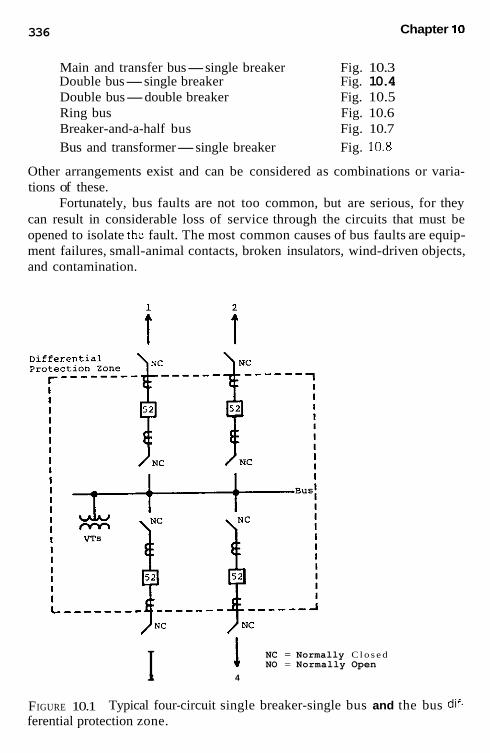
336 Chapter 10
Main and transfer bus-single breaker Fig. 10.3 Double bus-single breaker Fig. 10.4 Double bus-double breaker Fig. 10.5 Ring bus Fig. 10.6 Breaker-and-a-half bus Fig. 10.7 Bus and transformer-single breaker Fig. 10.8
Other arrangements exist and can be considered as combinations or varia- tions of these.
Fortunately, bus faults are not too common, but are serious, for they can result in considerable loss of service through the circuits that must be opened to isolate the fault. The most common causes of bus faults are equip- ment failures, small-animal contacts, broken insulators, wind-driven objects, and contamination.
i i
NC = Normally C l o s e d 1 NO = Normally Open I 3 4
FIGURE 10.1 ferential protection zone.
Typical four-circuit single breaker-single bus and the bus dif.

Bus Protection 337
Differential protection provides sensitive and fast phase and ground- fault protection and is generally recommended for all buses. In the figures the dashed-line box or boxes outline the bus differential protection zone: the primary protection zone. Backup is usually provided by the protection as- sociated with the connecting circuits. A second differential scheme is some- times used for very important buses.
10.2 SINGLE BREAKER-SINGLE BUS
The single-breaker-bus type (Fig. 10.1) is the most basic, simple, and ec- onomical bus design and is used widely, particularly at distribution and lower-transmission voltages. For this type of bus, differential is easy to apply as long as suitable CTs are available, with the protective zone enclosing the entire bus, as shown.
This bus arrangement provides no operating flexibility. All bus faults require opening all circuits connected to the bus. Breaker problems or main- tenance require that the circuit be removed from service. However, main- tenance may not be too much of a problem if maintenance on the entire circuit and the protection can be scheduled together.
4
NC = Normally Closed
FIGURE 10.2 Typical four-circuit single breaker-double bus with bus tie and the bus differential protection zones.

338 Chapter 10
One set of voltage transformers on the bus can supply voltage for the protection on all the circuits.
10.3
This is an extension of the single bus-single breaker arrangement (Fig. 10.2). It is used where a large number of circuits exist, especially at lower voltages, such as for distribution and industrial substations. It provides flex- ibility when the substation is fed from two separate power supplies. One supply connected to each bus permits operation with the bus tie (52T) either open or closed. If one supply is lost, all circuits can be fed by the other, with 52T closed. Separate differential zones for each bus are applied. A fault in one bus zone still permits partial service to the station by the other bus.
SINGLE BUSES CONNECTED WITH BUS TIE
10.4 MAIN AND TRANSFER BUSES WITH SINGLE BREAKER
Increased operating flexibility is provided by the addition of a transfer bus (Fig. 10.3). Normal operation is similar to Fig. 10.1, with all circuits supplied from the main bus. This bus is protected by a single differential zone (dashed lines). A bus fault requires tripping all breakers, thereby interrupting all service connected to the bus.
Normally, the transfer bus is not energized. For any breaker trouble or maintenance, that circuit is connected to the transfer bus by closing its nor- mally open (NO) disconnect switch and closing the bus tie (52T) breaker to continue service. Only one circuit is thus connected to the transfer bus at any one time. The protection associated with the bus tie breaker must be suitable and adaptable for the protection of any of the circuits of the main bus. This can require different settings, which must be made for each circuit transferred or operating with compromise protection for the period of trans- fer bus operation. This is a disadvantage from a protection standpoint. As a generality it is not desirable to switch or modify protection systems because the potential for error that can result is no protection or misoperation. One set of voltage transformers on the bus can supply voltage to all the protection for the several circuits.
10.5 SINGLE BREAKER-DOUBLE BUS
This arrangement (Fig. 10.4) provides high flexibility for system operation. Any line can be operated from either bus, the buses can be operated together, as shown, or independently, and one bus can be used as a transfer bus if a line breaker is out of service. The disadvantage is that it requires complicated

Bus Protection 339
I V T ' J
"air, BY5 Differential Protection Zone
NC = Normally Closed NO = Normally Open
FIGURE 10.3 Typical four-circuit single breaker-main bus with transfer bus and the bus differential protection zone.
switching of the protection: both the bus differential and line protection. Two differential zones for the buses are required. In Fig. 10.4, lines 1 and 2 are shown connected to bus 1, with lines 3 and 4 connected to bus 2. For this operation the differential zones are outlined: dashed for bus 1, and dash-dot for bus 2.
As for the previous bus arrangement (see Fig. 10.3), the bus tie pro- tection must be adaptable for the protection of any of the lines when 52T is substituted for any of the line circuit breakers. When a line breaker is bypassed and the bus tie (52T) breaker substituted, using one bus as a trans- fer bus, the differential protection on that bus must be removed from service.
Faults on either bus or associated circuits require tripping of all circuits connected to the bus $1 that time. Faults in the bus tie breaker (52T) must trip both buses and all circuits.

t
I I I I I I I I I I I I I I I I I I I I

Bus Protection 341
Voltage transformers for protection are required for each bus, as shown. However, line-side VTs are preferable to avoid switching if voltage is re- quired for line protection.
This bus arrangement is not in wide use in the United States, princi- pally because of the protection complications, and it is not recommended from that standpoint.
10.6 DOUBLE BREAKER-DOUBLE BUS This is a very flexible arrangement that requires two circuit breakers per circuit (Fig. 10.5). Each bus is protected by a separate differential, with zones as illustrated. The line protection operates from paralleled CTs, and this provides protection for the bus area between the two zones overlapping the two breakers. Line protection operates to trip both breakers.
FIGURE 10.5 differential protection zones.
Typical four-circuit double breaker-double bus and the bus

342 Chapter 10
With all disconnect switches normally closed (NC), as shown, a fault on either bus does not interrupt service on the lines. All switching is done with breakers, and either bus can be removed for maintenance.
Line-side voltage, either VTs or CCVTs, is necessary if required by the line protection.
10.7 RING BUS The ring bus arrangement (Fig. 10.6) has become quite common, particularly for higher voltages. High flexibility with a minimum of breakers is obtained. Each breaker serves two lines and must be opened for faults on either line. The bus section between the breakers becomes part of the line, so that bus protection is not applicable or required. The interconnection of the CTs for protection of each line is shown dashed in Fig. 10.6, and line faults must trip two breakers. If the ring is open for any reason, a fault on a line may separate the other lines and the bus.
Line protection voltage, if required, is obtained from VTs or, more commonly, at the higher voltages by CCVTs connected to each line.
1
I I I I ---- '------I ----
NC NC
NC = Normally closed 3
FIGURE 10.6 Typical four-circuit ring bus. Differential protection not applica- ble. Bus sections are protected as part of the lines or connected equipment, as shown dotted.

Bus Protection 343
10.8 BREAKER-AND-A-HALF BUS This arrangement (Fig. 10.7) provides more operating flexibility, but requires more circuit breakers than the ring bus. It, too, is widely used, especially for larger multicircuit, higher-voltage systems. Two operating buses each
' 1 Differential I Protection , zone NC
I I I
I I I L __________--- - - A
I I Bus B
NC = Normally Closed
FIGURE 10.7 Typical four-circuit breaker-and-a-half bus and the bus differ- ential protection zones. The mid-bus sections are protected as parl of the lines or connected equipment, as shown dotted.

344 Chapter 10
have separate differential protection. Each line section is supplied by both buses through two circuit breakers. The center circuit breaker serves both lines; hence, the half designation.
The CT interconnections are shown for each line section as dashed lines in Fig. 10.7. Voltage for line relays must use line-side CCVTs or VTs. Line faults trip two breakers, but do not cause loss of service to the other lines if all breakers are normally closed as shown.
10.9 TRANSFORMER-BUS COMBINATION
This is the single breaker-single bus of Fig. 10.1, with a transformer bank directly connected to the bus as shown in Fig. 10.8. The advantage is the cast saving of the circuit breaker between the transformer and the bus. It is practical for small stations, such as distribution, where there is only one transformer to supply several circuits. Here a fault in either the transformer
i
I I
FIGURE 10.8 Typical four-circuit single breaker bus and transformer with combined bus-transformer differential protection zone.

Bus Protection 345
or on the bus requires that all service be interrupted, with or without the intervening breaker.
The differential zone includes both the bus and the transformer (dashed lines). In these applications transformer differential relays must be used. The application and the setting for these are presented in Chapter 9.
10.10 GENERAL SUMMARY OF BUSES
Tables 10.1 and 10.2 provide a brief summary of the several bus arrange- ments outlined in the foregoing. The far-right column of Table 10.2 indicates the tripping requirements, in the event that one of the breakers fails to clear a fault on a circuit connecting to the bus. This could result from malfunction of the protective system, or from the breaker failing to open properly. Local breaker failure-hackup protection is assumed, and this is discussed in Chap- ter 12.
10.1 1
Complete diffcrential protection requires that all circuits connected to the bus be involved, because it compares the total current entering the zone with the total current leaving the zone. Except for a two-circuit bus, this means comparisons between several CTs that are operating at different energy lev- els and often with different characteristics. The most critical condition is the external fault just outside the differential zone. The C T s on this faulted circuit receive the sum of all the current from the other circuits. Thus, it must reproduce a potential high-current magnitude with sufficient accuracy to match the other C T secondary currents and avoid misoperation; therefore, CT performance is important. The relays and CTs are both important mem- bers of a “team” to provide fast, sensitive tripping for all internal faults, yet restrain all faults outside the differential zone. Two major techniques are in use to avoid possible unequal CT performance problems: (1) multirestraint current and (2) high-impedance voltage. A third system employs air-core transformers to avoid the iron-core excitation and saturation problems. All are in practical service. They exist with various features, depending on the design, and each has specific application rules. These should be followed carefully, for they have been developed to overcome the inherent deficiencies of conventional CTs on both symmetrical and asymmetrical fault currents.
DIFFERENTIAL PROTECTION FOR BUSES
10.1 1.1 Multirestraint Current Differential
Multirestraint current differential is the most versatile method for general application using conventional current transformers, but in general, is more
TABLE 10.1 General Summary of Advantages and Disadvantages
0 a m
Fig. no. Arrangement
10.1 Single breaker, single bus
10.2 Double bus with bus tie
10.3 Main and transfer bus
10.4 Single breaker, double bus
- 1.
2.
1.
2.
3.
1. 2.
3.
4.
1. 2.
3.
Advantages
Basic, simple, economical One bus voltage for all circuits Two power sources to feed two buses One source lost, load transferred One bus out, partial service available One differential zone Only one circuit transferred Breaker, relays transferred for maintenance, etc. Voltage only on main bus High flexibility Any line operated from either bus One bus available as a transfer bus
Disadvantages
1. No operating flexibility 2. All breakers opened for bus fault 3. Circuit removed for maintenance or problems
1. Circuit removed for maintenance or problems 2. Bus tie breaker fault trips both buses 3. Voltage required on each bus
1. Bus tie breaker protection suitable for each circuit 2. Bus fault trips all breakers 3. Potential for error 4. Bus tie protection adaptable for all circuits
1. Complicated (undesirable) switching of protection 2. Bus tie breaker protection suitable for each circuit 3. With line breaker bypassed differential removed from
4. Bus tie breaker fault trips all breakers
!? one bus x
4 5. Voltage required for each bus 0
A

10.5 Double breaker, 1. double breaker 2.
3.
4.
5.
10.6 Ring bus 1. 2. 3.
10.7 Breaker and a half 1,
2.
10.8 Bus and 1, transformer
Very high flexibility 1. Overlapping protection 2. zones 3. Bus fault does not 4. interrupt service 5. All switching by breakers Either bus can be removed High flexibility 1. Minimum breakers 2. Bus section part of 3. line, no bus 4. differentials 5.
More operating 1. flexibility 2. Bus section part of 3. lines 4.
5. 6.
Saves breaker 1. between bus and transformer
Protection in service during breaker maintenance P :
Requires line side voltage m” Two breakers trip for line faults a
fn
0
Two breakers per line Line protection from two CTs
0 3
Requires line side voltage Relays in service during breaker maintenance Line faults trip two breakers Local backup not applicable Open ring and subsequent fault may result in undesired system separation Required more breakers Center breaker serves two lines Requires line side voltage Two bus differential zones Local backup not applicable Line faults trip two breakers Transformer and bus differential combined. Fault location by inspection
L -l

TABLE 10.2 General Summary of System Buses
Required Breaker failure: Required for each Total Three-phase local backup
Fig. Bus for one line added line four lines voltage supply requires Bus type no. sect. Bkrs. Disc. Bkrs. Disc. Bkrs. Disc. for line relays tripping"
Single bus- single breaker
Single buses with bus tie
Main and transfer bus
Double bus- single breaker
Double bus- double breaker
Ring bus
Breaker and a half
10.1
10.2
10.3
10.4
10.5
10.6
10.7
1 2
For two-line minimum
3 6 3 5
2 7
2 4
For two-line minimum
2 4 For two-line
minimum 3 6
1 2
1 2
1 3
1 5
2 4
1 2
Each two
3 6 lines
4 3 1 on bus
5 10 On each bus
5 14 1 on main bus
5 22 1 on each
8 16 On each line busc
4 8 On each line
6 12 On each line
All breakers on bus
All breakers on busa
All breakers on bus
All breakers on busb
All breakers on bus
Adjacent breaker and remote line terminal
All breakers on bus; for center breaker, adjacent breaker and remote line terminal
~~
"Also. the remote terminal of the stuck breaker must be opened by relay action at that terminal andlor by transfer tripping. 'Failure of the bus tie breaker requires tripping all circuits on both buses. 'Line voltage preferred to avoid voltage transfer as lines are switched to a different bus.

Bus Protection 349
difficult to apply. However, each manufacturer has developed application connections and criteria that simplify the process. Multirestraint relays are used with a restraint winding connected to each circuit that is a major source of fault current. Feeders and circuits with low-fault-current contribution may be paralleled. The fundamentals discussed in Section 9.5 apply here. All CTs are connected in wye and to the restraint windings because there are no phase-shift problems with buses except for the example shown in Fig. 10.8.
These schemes are designed to restrain correctly for heavy faults just outside the differential zone, with maximum offset current as long as the CTs do not saturate for the maximum symmetrical current. This can be accomplished by (3 ratio selection and by keeping the secondary burden low. Thus, it is important and recommended that no other devices be con- nected in the differential circuits. The restraint windings of the differential relays normally have quite low impedance; consequently, the major burden encountered is often that of the lead> connecting the CTs to the relays. This can be kept low by use of large wire, which is also desirable to minimize physical damage. Accidental breakage or an opening in the differential cir- cuit can result in incorrect operation and loss of a critical part of the power system.
Multirestraint bus differential relays do not have ratio taps. These are not required in most applications, for a common CT ratio normally can be obtained among the several bus CTs. Otherwise, auxiliary CTs are required for the CTs that do not match. When these are used it is desirable that they step down the current if possible. This reduces their secondary burden, as discussed in Chapter 5.
The relays exist with up to six restraint circuits, and can have either fixed or variable restraint characteristics. Typical sensitivities for internal faults are on the order nf 0.15 A, with operating times of 50-100 ms.
10.1 1.2 High-Impedance Voltage Differential
This scheme loads the CTs with a high impedance to force the error differ- ential current through the CTs instead of the relay-operating coil. The basic principles are illustrated in Fig. 10.9. For an external fault, the maximum voltage V, across the differential relay Z , will occur if the CT on the faulted circuit (1) is completely saturated and the other CTs (2 and 3) do not sat- urate. This is a worst-case, because in practice all CTs may not saturate on light external faults or will have varying degrees of saturation for the heavy faults. An empirical margin with a safety factor is provided by the manu- facturer to modify this maximum voltage calculation for setting the relay. This calculation is made for both the maximum symmetrical three-phase and
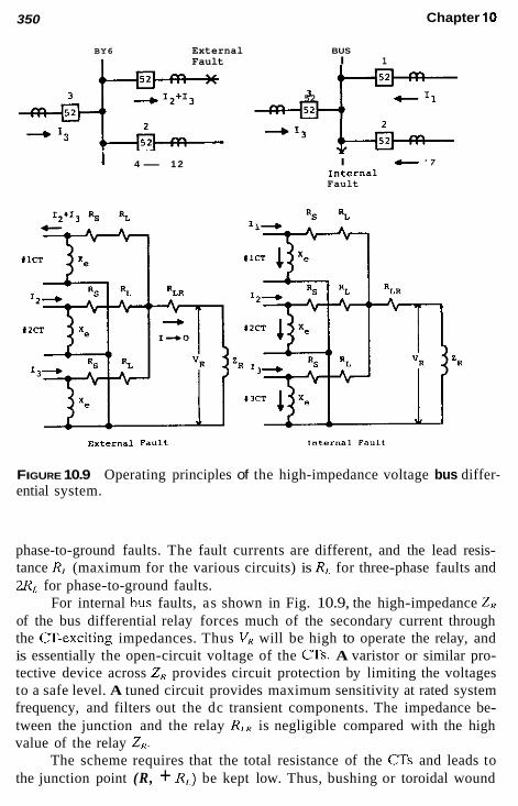
Chapter 10 350
BY6 External Fault
I 4- 1 2
BUS I 1
2 2 7 52
I c ' 7 Internal Fault
External f."lt Internal F a u l t
FIGURE 10.9 Operating principles of the high-impedance voltage bus differ- ential system.
phase-to-ground faults. The fault currents are different, and the lead resis- tance R,. (maximum for the various circuits) is R,, for three-phase faults and 2R,. for phase-to-ground faults.
For internal bus faults, as shown in Fig. 10.9, the high-impedance Z , of the bus differential relay forces much of the secondary current through the (JT-exciting impedances. Thus V, will be high to operate the relay, and is essentially the open-circuit voltage of the CTs. A varistor or similar pro- tective device across Z, provides circuit protection by limiting the voltages to a safe level. A tuned circuit provides maximum sensitivity at rated system frequency, and filters out the dc transient components. The impedance be- tween the junction and the relay R,., is negligible compared with the high value of the relay Z,.
The scheme requires that the total resistance of the CTs and leads to the junction point (R, + R,,) be kept low. Thus, bushing or toroidal wound

Bus Protection 351
CTs, where their secondary impedance is very low, can be used, and they should be interconnected together as near the CT locations as possible, pref- erably equidistant, so that the several R,. values are essentially equal and low.
All CTs should have the same ratio and operate on the full winding. Operating at CT taps is not recommended, but if necessary, the windings between the taps must be completely distributed, and the unused end well insulated to avoid high-voltage breakdown from the autotransformer effect. Auxiliary CTs are not recommended. If they are required, a detailed analysis or special relays may be applicable. One type of relay employs added re- straint circuits for applications with widely diverse CTs.
The several limitations outlined are not too difficult to meet with mod- ern CTs and proper bus design, so this is a very effective and widely used bus protection system.
Typical operating times are on the order of 20-30 ms, and if a sup- plementary instantaneous unit is used for high-current internal faults, times of 8-16 ms are available.
10.1 1.3 Air-Core Transformer Differential
The major problem in differential schemes results because of the CT iron, which requires exciting current and saturates at high fault currents. By elim- ination of the CT iron, this problem does not exist, and a simple, fast, reliable bus differential system results. This is known as the linear coupler differ- ential scheme, and several of these are in service. It has not become popular primarily because existing and conventional CTs cannot be used, nor can linear coupler CTs be used for other applications.
The linear coupler in appearance is the same as conventional iron-core CTs and can be mounted on a bushing or connected as a wound-type CT in the primary circuit. It operates as an air-core mutual reactor where
where M has been designed to be 0.005 fl at 60 Hz. Thus a secondary voltage of 5 V is induced for 1000-primary amperes. The linear coupler secondaries for each circuit on the bus are all connected in series and to a sensitive relay unit. For an external fault or load, the sum of the voltage for all current flowing into the bus is equal and opposite the voltage developed by the current flowing out of the bus. Thus, the voltage across the relay is essentially zero for no operation.
For an internal fault, with all current flowing into the bus, the linear coupler secondary voltages add to produce an operating voltage. Thus, the relay-operating current (IR) is

352 Chapter 10
(10.2)
where 2, is the relay coil impedance and Z, is the linear coupler secondary impedance. Typical values of Z , are about 2-20 for Z,. Lead impedance is not significant with these values. The relays operate from 2 to 50 mA for high sensitivity. Typical times are 16 ms and less.
The system is quite flexible because the linear coupler secondaries do not have to be shorted if open-circuited, and circuits can be added or sub- tracted with minimum problems. Changing the number of circuits affects the value of the Zc sum, which is basically offset by a corresponding change in the V,,, sum.
If the primary circuit is subject to high frequencies, such as occur with large capacitors or back-to-back switching of capacitors, secondary lightning arrestors may be required. Linear couplers very efficiently transform all frequencies.
10.1 1.4 Moderate High-Impedance Differential
This is a combination of the percentage and high-impedance voltage differ- ential techniques that provides low-energy, high-speed bus protection. It can be applied with CTs of varying saturation characteristics and ratios and can be used with magneto-optic current transducers. When used with 5-A CTs, special auxiliary CTs are required for each circuit. Diodes separate the CTs’ positive and negative half-cycles, developing a unidirectional sum current to provide percentage differential restraint.
For internal faults, all currents into the fault provide a high voltage, similar to that produced in the high-impedance differential scheme for op- eration. For external faults, when the currents into the bus equal the current out, a low-voltage exists to inhibit operation.
Correct performance is assured where CTs may saturate because it takes about 2-3 ms of each half cycle for saturation to occur, as illustrated in Fig. 5.15. This provides ample time for correct performance.
10.12 OTHER BUS DIFFERENTIAL SYSTEMS
Several other schemes exist, but are in limited use. These are the time- overcurrent, directional comparison, and partial differential systems.
10.1 2.1 Time-Overcurrent Differential
In this the secondaries of all the current transformers are paralleled and connected to an inverse-time-overcurrent (51) relay. There is no restraint,

Bus Protection 353
so the relay must be set above the maximum CT’s magnetizing difference current for the external fault.
The inverse characteristic, which provides long times for low-current magnitudes, is an advantage to override unequal CT saturation, particularly on the dc component. Thus, the dc time constant should he short for these applications. Typical operating times for these schemes are 15-20 cycles (60-Hz base) for internal faults where the total fault current adds for relay operation. This provides a relatively inexpensive but slow differential, and one that is difficult to set with security except through long experience. It is used only for small, low-voltage buses.
10.12.2 Directional Comparison Differential
A directional-sensing unit, as described in Chapter 3, is connected to each bus circuit “looking into” the bus, with the trip contacts in series. For normal operation, one or more contacts are opened by the load passing through the bus. For internal faults, all contacts should close to trip the bus. Normally closed contacts are necessary for feeder circuits with no feed to the fault.
The major advantage is its almost complete independence of CT per- formance, characteristic, and ratio. The disadvantages are relatively high cost (relays required for each circuit), a voltage or reference source is required, and contacts in series are difficult to coordinate. It has not been in general use in recent years.
10.12.3 Partial Differential
The partial differential scheme is used frequently to provide protection for buses in industrial and lower-voltage distribution substations. It is applicable where there are feeder circuits that (1) supply negligible current to bus faults, and (2) do not have adequate or suitable CTs for a complete differential application. Good examples are feeders supplying only static or induction motor loads and when there is a great diversity in their power ratings. A typical bus of this type is shown in Fig. 10.10. The CTs of the fault-source circuits are paralleled and connected to inverse-time-overcurent (51) relays. As illustrated in Fig. 10.10b and d, negligible current flows in the 51 relays for external faults in the sources. The total fault current is available to op- erate the relays for bus and for faults out on the feeders. This requires that the 51 relays be time-coordinated, with the protection on all the feeders not included in the differential. The use of an inverse relay and this scheme provides a good compromise for low-voltage substation buses. Three-phase connections are included in Fig. 9.26.

354 Chapter 10
source source 1 ( 2
(81
Feeders Peeders
lbl source
Fault
c
Feeders
FIGURE 10.10 Partial differential bus and feeder backup protection: (a) sin- gle-line diagram for a typical bus arrangement; (b) operation for source-side faults; (c) operation for bus and feeder faults; (d) operation for adjacent bus faults.

Bus Protection 355
(51 source
I
0"s
Fault c
p to Feeders
Idl
""I"
Feeders
FIGURE 10.10 Continued

356 Chapter 10
If current-limiting reactors are used in the feeder circuits, distance-type relays (21) can be substituted for the 51 relays. The 21 relays are set into, but not through, the lowest reactor impedance. This does not require selec- tive settings with the feeder protection, and so avoids the time delay nec- essary with the 51 relays to provide fast and sensitive bus protection. It does require bus voltage for the distance relays.
10.13 GROUND-FAULT BUS
The bus supports and the substation equipment are insulated from the ground and are all connected together to be grounded at one point through an over- current relay. A ground fault that involves this interconnection passes current through the relay to trip the respective protected area. A separate fault de- tector is used to supervise tripping for added security. This relay operates on system zero-sequence current or voltage. This scheme basically is not used in the United States because of relatively higher cost, difficulties of construction, and difficulties in protecting personnel.
10.14 PROTECTION SUMMARY
Differential protection should be considered and applied wherever possible for all buses as the primary protection. Although bus faults are relatively infrequent, they can be very disruptive to a power system; therefore, fast, sensitive protection, as available through the various differential systems, is recommended. The most probable causes of bus faults are animals, wind- blown objects, and insulation failures (natural or gunshot). Lightning may result in bus faults, but stations and substations generally are well shielded and protected against lightning. The protection applied to the several circuits connected to the bus generally provides the backup protection for the bus, or the primary protection where bus differentials are not or cannot be applied.
BIBLIOGRAPHY
See the Bibliography at the end of Chapter 1 for additional information. ANSIjTEEE Standard C37.97, Guide for Protective Relay Applications to Power
Buses, IEEE Service Center. Udren, E. A., Cease, T. W., Johnston, P. M., and Faher, K., Bus differential protection
wilh a combination of CTs and magneto-optic current transducers, 49th Protective Relay Engineers Conference, Georgia Institute of Technology, Atlanta, GA, May 3-5, 1995.

Motor Protection
11.1 INTRODUCTION
The protection of motors varies considerably and is generally less standard- ized than the protection of the other apparatus or parts of the power system. This results from the very wide variety of sizes, types, and applications of motors. The protection is principally based on the importance of the motor, which usually is closely related to size. This chapter deals with motors and protection applied directly to them. Backup often associated with the con- necting circuits is discussed in Chapter 9. The present discussion is for motors that are switched by a circuit breaker, contactors, or starters, and for which the protection is separate from these devices and from the motor. Essentially, this covers motors at the 480- to 600-V level and higher. Not covered specifically or directly arc motors for which the protection is built into the motor or starter, or for which fuses are the only protection.
11.2 POTENTIAL MOTOR HAZARDS The potential hazards normally considered are
1. Faults: phase or ground 2. Thermal damage from
a. Overload (continuous or intermittent) b. Locked rotor (failure to start, or jamming)
357

358 Chapter 11
3. Abnormal conditions a. Unbalanced operation b. Undervoltage and overvoltage c. Reversed phases d. e. Unusual ambient or environmental conditions (cold, hot,
f. Incomplete starting sequence
High-speed reclosing (reenergizing while still running)
damp)
These are for induction motors, which represent the large majority of all motors in service. For synchronous motors, additional hazards are
4. 5 . 6. Synchronizing out of phase
Loss of excitation (loss of field) Out-of-step operation (operation out of synchronism)
These can be reclassified relative to their origins:
A. Motor-induced 1. 2. Bearing failure 3 . Mechanical failures 4.
B. Load-induced 1. Overload (and underload) 2. Jamming 3 . High inertia (Wk')
1. High ambient temperature 2. 3. Cold, damp ambient temperature
1. 2. Overvoltage 3. Undervoltage 4. Phase reversal 5.
1. 2. High duty cycle 3. Jogging 4. Rapid or plug reversing
Insulation failure (within motor and associated wiring)
Synchronous motors: loss of field
C. Environment-induced
High contaminant level: blocked ventilation
I). Source- or system-induced Phase failure (open phase or phases)
Out-of-step condition resulting from system disturbance
Synchronizing, closing or reclosing out of phase E. Operation- and application-induced

Motor Protection 359
Operating - Overload Thermal limit curve
Accelerating Thermal Limit CYrVe
I
I, ~ Asymmetrical I .. '.-
Load Locked Rotor Current t current Per ""it
or Amperes
FIGURE 11 . I Typical induction motor characteristics
11.3 MOTOR CHARACTERISTICS INVOLVED IN PROTECTION
The primary motor characteristics available and involved in the protection are
Thermal capability curve, which should inciude the permissible locked-rotor thermal limit
1. Starting-current curves 2.
3. The K constant (R,JR,,)
These characteristics normally are obtained from the motor manufacturer and are basic for the application of protection. Typical curves are illustrated in Fig. 11.1.

360 Chapter 11
The maximum starting current curve is at rated voltage. Currents for lower voltages exist to the left, with the knee at a higher time level.
The thermal limits are three different curves, which often approxi- mately blend together to a general curve, such as that shown. Thermal limits are relative indeterminate zones that engineers desire to have represented by a specific curve.
1. The higher-current portion indicates the permissible locked rotor times. This is the time the rotor can remain stalled after the motor has been energized before thermal damage occurs in the rotor bars, rotor end rings, or in the stator, whichever is the limit for a par- ticular design.
In very large motors this locked-rotor thermal limit can he less than the starting time, so these motors must start rotating instantly to avoid thermal damage. This curve is from locked-rotor current at full voltage to that current at the minimum permissible starting voltage. The accelerating thermal limit curve from locked-rotor current to the motor breakdown torque current, which is about 75% speed. The operating or running thermal limit curve, which represents the motor overload capacity during emergency operation.
2.
3.
11.4 INDUCTION MOTOR EQUIVALENT CIRCUIT
As an aid in the protection and for protection analysis, the equivalent motor diagram can be reduced as shown in Fig. 11.2. Typical values for induction motors in per unit on the motor kVA or kV, as shown in Fig. 11.2b arc R . and R, = 0.01 pu, j X , = j3.0 pu, and j X = jX; = 0.15 pu, and from these, the typical locked rotor or starting is
1 - - 6.67 pu (11.1)
1 = - - - - j X 3 0.15
This is the symmetrical value; the asymmetrical current is higher (see Fig.
Because the shunt jX, is high relative to the other impedances, the 11.1).
equivalent at the motor input reduces with the foregoing typical values to
Z,, = Z,, = 0.144&2.39" (11.2)
or practically equal to jX3 = 0.15 pu, as commonly used for a stalled motor (S = 1.0). If the motor is running (S = 0.01), the foregoing values give:

Motor Protection
ld
361
lbl jx m
1nput - Rr For Positive
'ZM1'ZM2' s sequence
R For Negative h s e g u e n c e
Rp = Stator Resrstance
]xS = stator Leakage reactance at rated frequency
R = Rotor Resistance
]xr = ~ o t o r Leakaqe reactance at rated frequency
jz ~ çhunt excitinq impedance m jx I jx + j x = - jxd '
S = Synchiono~s RPM - RotOC RPM = 1.0 stalled Çynchronous RPH = O+ runninq
FIGURE 11.2 Equivalent-circuit diagrams for induction motors: (a) equivalent diagram for an induction motor; (b) simplified equivalent induction motor diagram.
Z,, = 0.927- and Z,, = 0.144- pu (11.3)
Thus, practically,
Z,, = 0.9 to 1.0 pu and Z,, = 0.15 pu (11.4)
From stalled to running the positive-sequence impedance changes from ap- proximately 0.15 to 0.9 OI 1.0 puI whereas the negative-sequence impedance remains essentially the same, at approximately 0.15 pu. Again these are on the base of the rated motor kVA, which is roughly equal to the motor horse-

362 Chapter 11
power (hp). These values will vary with each individual motor, but these typical values are close and quite useful if specific data are not available.
11.5 GENERAL MOTOR PROTECTION
Protection for motors exists in many forms, a variety of designs, and either packaged individually or in different combinations. Each has its features, which will not be restated or evaluated here. The fundamentals and basic aim should be to permit the motor to operate up to, hut not to exceed, its thermal and mechanical limits for overloads and abnormal operation con- ditions and, to provide maximum sensitivity for faults. These can usually be achieved in general terms as follows:
11.6 PHASE-FAULT PROTECTION
Instantaneous nondirectional overcurrent relays (SO, 51) can be used to pro- tect induction motors. Faults generally provide current greater than the locked-rotor starting current, except for turn-to-turn faults. Considerable current can flow between turns, but unfortunately, very little evidence of this is available at the motor terminals until it develops into other types, phase- to-ground or phase-to-phase.
The motor is the end device in the electrical system, so instantaneous relays can be used. There is no coordination problem. The induction motor backfeed to system faults is relatively small ( l /X ; + offset) and decays rap- idly in a few cycles; therefore, nondirectional relays can be applied. The CT ratios supplying these relays should he selected such that the maximum motor current provides between 4- and 5-A secondary current.
Phase-instantaneous relays should be set well above the asymmetrical locked rotor and well below the minimum fault current. This can be equated where I,,, the locked rotor symmetrical is
1 I,, = (11.5) x,, + x;
where X,, is the total reactance (impedance) of the power system or source to the motor. This equation is similar to Eq. (ll.l), where the maximum starting or locked-rotor current is with a very large or infinite source, so X,s approaches zero. A fault at the motor is
1 1 3 , = - (11.6)
XI,

Motor Protection 363
and for a phase-to-phase fault with X,, = X,,
0.866 I+, = 0.8661,, = -
X1.S (11.7)
If PR is the ratio of the relay pickup (ipu) to locked-rotor current,
I,, P,< = - 1l.R
Typically, P,, should be 1.6-2.0 or greater. If P,. is the ratio of the minimum fault-to-relay pickup current,
(11.8)
(11.9)
Desirably, P p should be 2-3 or greater. From Eq. (11.9) and (11.8),
I,, = PJ,.,, = P,:PgLK
and
or the three-phase solid fault at the motor should be 1.155 P,P,, or larger for good instantaneous overcurrent protection. If the minimum recommended values of PN = 1.6 and P, = 2, the three-phase fault should be 3.7 times the locked rotor current. If Px = 2, P, = 3, the three-phase fault should be at least 6.9 times larger than the locked rotor current.
Equating Eq. (11.7) and (11.10) and substituting Eq. (11.5) yields
Thus, with Pn = 1.6, Pr = 2:
0.866Xz x - = 0.37lX: I s - (2 X 1.6) - 0.866
(1 1.11)
and with the typical X: = 0.15, X,, = 0.056 pu, or with PR = 2, P,.. = 3, and X: = 0.15, X,, = 0.025 pu. This defines the source impedance, which should be as indicated or less for instantaneous overcurrent protection. The per unit values in the examples are on the motor kVA, kV base, where

364 Chapter 11
(horsepower)(0.746) (efficiency)(power factor) kVA,,& = (1 1.12)
In many applications the source X,,, for all practical purposes is the reactance of the supply transformer, which is connected on its primary to a large utility, which is a relatively infinite source. Furthermore, the supply transformer is generally supplying other loads and so is much larger than any specific motor; consequently, its reactance on the motor base will tend to be small. This can be illustrated with the example of Fig. 9.19, where a 2500-kVA transformer with 5.75% X is shown supplying an 800-A feeder. Suppose that this is a motor: 800 A at 480 V equals 665 kVA. At 665 kVA, the transformer reactance X,- is 5.75(665)/2500 = 1.53% or 0.0153 pu. As- suming X, is essentially equal to X,,, this is well below the 0.025-pu limit derived from Eq. 11.11 to provide good instantaneous relay protection.
If the recommended foregoing setting criteria of P* and P+ cannot be met, or when more sensitive protection might be desired, the instantaneous relay (or a second relay) can be set more sensitively if delayed by a timer. This permits the asymmetrical-starting component to decay out. A typical setting recommendation for this is a P,? of 1.1-1.2, with a time delay of 0.10 s (six cycles at 60 Hz).
If on loss of voltage, running motors are transferred from a bus to a hot bus, or if high-speed system reclosing reenergizes motors before their residual voltage has dropped to about 33% rated, very high transients can occur. These currents are very hard on motors unless specifically designed for them. Careful attention must be given to set the relays above this tran- sient if the condition is tolerable.
When the foregoing criteria indicate that there is not sufficient margin between locked-rotor and fault current, differential protection is indicated.
11.7 DIFFERENTIAL PROTECTION
Differential protection (87) is preferred. However, for some motors the two ends of the windings may not be available, and differential protection cannot be applied. If both ends of the windings are available, the best differential, in terms of sensitivity, speed, and security, is to pass the conductors of the windings through a flux summation (ring) CT, as shown in Fig. 11.3a. These CTs are described in Chapter 5 and also applied for smaller generator pro- tection in Chapter 8. Typical maximum openings or windows in these CTs are about 8 in. in diameter. With a fixed ratio of 50:5 and a sensitive in- stantaneous overcurrent relay (50), the combination can provide a pickup of nearly 5-A primary current. This is a flux-balancing differential, independent of load and starting current magnitudes and with only one CT per phase, so

Motor Protection 365
Motor
A
B
C
(b)
FIGURE 11.3 Differential protection for motors where the neutral leads are available: (a) with flux summation (ring)-type CTs and instantaneous over- current relays (50); (b) with conventional-type CTs and differential relays.
that matching (3 performance does not exist. Internal phase and ground protection is provided within the motor and up to the CT location. Other protection is required for the connections to the circuit breaker, starter, and so on. The limitation is the conductor size relative to the CT opening.
Conventional differential with CTs in the neutral and output leads should be applied where the flux summation type cannot be used. Normally, the two sets of (3s would be of the same type and ratio, so conventional 87 two-restraint differential relays are applicable, as illustrated in Fig. 11.3b. With equal CT ratios the secondary currents through the relay restraint wind- ings (R) would he essentially the same for all external faults and load, and the operating current (OP) very small to zero. For motor faults between the two sets of CTs, all of the fault current flows through the (OP) operating

366 Chapter 11
winding for high sensitivity to both phase and ground faults. The line-side CTs should be as shown, so that the differential zone includes the circuit breaker and connecting leads as well as the motor.
11.8 GROUND-FAULT PROTECTION
As for phase protection, instantaneous overcurrent relays are applied for ground-fault protection (50G, 50N, 51N). Where applicable, the preferred method is to use a flux summation-type current transformer, with the three motor conductors passed through the C T opening. This provides a magnetic summation of the three-phase currents so that the secondary output to the relay is zero-sequence (31J current. This is shown in Fig. 11.4% The CT ratio, commonly 505 , is independent of motor size, whereas the conven- tional CTs in the phases must be sized to the motor load. The advantage is high sensitivity with good security, but is limited by the conductor size that can he passed through the CT opening. As indicated in the preceding section, typical sensitivity is 5-A primary current.
For larger motors and conductors, ground relay in the neutral must be used as in Fig. 11.4b. Although load influences the CT ratios, the ground relay can be set sensitively and well below motor load. 50N must be set above any “false” residual current that can result from the unequal perfor- mance of the three ms on high, unequal-offset, starting currents. This is difficult to predetermine, but the probability of a problem is very low if the phase burdens are balanced and the Cr voltage developed by the maximum- starting current is not more than 75% of the CT accuracy class voltage. A lower 50N relay tap and consequent higher burden may help by forcing all three CTs to saturate more evenly. Resistance in the neutral circuit may also help. This increased burden, however, should not be great enough to signif- icantly inhibit the relay sensitivity. These latter “fixes” are used generally after trouble is encountered during start-up. Time delay could he used until the offset has decayed, but this delays tripping for actual faults.
With ground-fault limiting, as is common in supply systems for motors, the ground-fault current will be smaller than for phase faults. If high-resis- tance grounding is used (see Chap. 7), ground-fault currents will be in the order of 1- to 10-A primary. The protection of Fig. 11.4a can provide rea- sonable sensitivity for these systems if the ground-fault current is greater than 5 A. Considerably more sensitive protection can be obtained by the application of a product overcurrent relay (32N). This general type was described in Section 9.17. For this application a relay with a current coil and a voltage coil is used. It operates on the product of voltage times current and for use in high-resistance, grounded systems, the maximum torque oc-

Motor Protection 367
Conventional Ring-type Type C T s CT
n A
8
C
Conventional
A
B
c
Ground Relay
(b)
FIGURE 11.4 Ground overcurrent protection for motors: (a) with the three conductors passed through a flux summation-type current transformer; (b) with conventional-type current transformers.
curs when the current leads the voltage by 45". The current coil is connected in the neutral of the CTs in place of 50N of Fig. 11.4b, and the voltage coil across the grounding resistor and in parallel with 59G in Fig. 7.9 or 7.10. The polarity is that the relay will operate when zero-sequence current flows into the motor. As indicated in Chapter 7, the current in high-resistance grounding is low, but the zero-sequence voltage is high. Typical pickup for this product overcurrent relay is about 7-8 mA with 69.5 V. This is well below the ground-fault levels of 1-10 A.
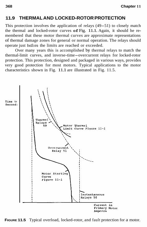
368 Chapter 11
11.9 THERMAL AND LOCKED-ROTOR PROTECTION
This protection involves the application of relays (49-51) to closely match the thermal and locked-rotor curves of Fig. 11.1. Again, it should he re- membered that these motor thermal curves are approximate representations of thermal damage zones for general or normal operation. The relays should operate just before the limits are reached or exceeded.
Over many years this is accomplished by thermal relays to match the thermal-limit curves, and inverse-time-overcurrent relays for locked-rotor protection. This protection, designed and packaged in various ways, provides very good protection for most motors. Typical applications to the motor characteristics shown in Fig. 11.1 are illustrated in Fig. 11.5.
Time ii Second:
FIGURE 11.5 Typical overload, locked-rotor, and fault protection for a motor.

Motor Protection 369
Thermal relays are available in several forms:
1. A “replica” type, where the motor-heating characteristics are ap- proximated closely with a bimetallic element within a current heater unit. These operate on current only. Relays operating from exploring coils, usually resistance temper- ature detectors (RTD), embedded in the motor windings. These operate on winding temperature only, and the detectors are placed in the motor by the designer at the most probable hot spot or danger area. These are common in motors from about 250 hp and higher, but may not he installed in some motors unless specified. Relays that operate on a combination of current and temperature. Care should he exercised with combinations when both are re- quired for relay operation to ensure that there are no operating conditions that may not be covered. High current and high tem- perature normally indicate problems, hut high current without measurable high temperature might exist for overheating in the rotor, bearings, drive machine problems, and in the controllers or connections. For these, the combination may provide limited to no protection.
2.
3.
The comparison of motor-starting and inverse-time-overcurrent relay curves on the same plot, as is commonly done and shown in Fig. 11.5, can provide false information. This may occur where the space between the starting current and locked-rotor limit is very narrow, which it usually is for very large motors. Often in these situations it appears possible to set the overcurrent relay so that its characteristic is above the motor start curve and below the locked-rotor limit, only to discover in service that the overcurrent relays operate under normal start.
Actually, the curves for motor starting and relay operation are two quite different characteristics. The motor-starting curve is a plot of the changing current with time from locked-rotor or starting condition to the motor-load-operating current. The relay characteristic represents the oper- ating times for different constant-current values. With the overcurrent relay typically set at about one-half locked-rotor current or less, it begins operation at the moment the motor is energized. Unless the starting current drops below the relay pickup before the relay times out, it will initiate undesirable tripping. Relay-operating times for variable current are not directly available from its time characteristic. This is a complex calculation, hut manufacturers have developed criteria for individual relays. The microprocessor-type relays provide better protection (see Sec. 11.16).

370 Chapter 11
11.10 LOCKED-ROTOR PROTECTION FOR LARGE MOTORS (21)
As indicated, the permissible locked-rotor current can he very close or less than the starting current. In general, this occurs for very large modern mo- tors. The protection for this can be a zero-speed switch built into the motor. If the motor does not accelerate on energization to open or operate the switch in a prescribed manner, the supply circuit is opened. The concerns with using this type of protection are that the motor could start and lock up at less than full-load speed, plus the difficulty of testing and maintenance.
Protection for locked rotors can be obtained by applying a distance relay, as described in Chapter 6. The relay is set looking into the motor (Fig. 11.6). The ratio of system voltage and starting current is an impedance, which can be determined and plotted as a vector on the R-X diagram. From a specific value at start, it increases in magnitude and changes phase angle as the motor accelerates. The distance 21 relay is set so that its MHO op- erating circle encloses the locked-rotor impedance vector. When the motor is energized by closing breaker 52, the distance 21 relay operates and the timer 62 is energized. By using an ac-operated timer, variable time with voltage is obtained to match the longer permissible locked-rotor times at
\ Impedance during Start
/+ate area within circle
TdC f 6 *
Trip
FIGURE 11.6 Locked-rotor protection with a distance (21) relay and timer.

Motor Protection 371
lower voltage. The heavy starting current can cause the voltage to drop momentarily during the starting period. If the start is successful, the impe- dance phasor moves out of the 21 operating circle before the 62 timer contact closes. If the start is unsuccessful, the impedance vector stays in the circle, and when timer 62 operates, the trip is initiated. The timer is set as deter- mined by the permissible locked-rotor time curve from full voltage to about 75 or 80% voltage. This protection does not cover failure to accelerate to full speed, nor to pull out with rotation continuing.
11.1 1
The most common cause of unbalance for three-phase motors is the loss of phase resulting from an open fuse, connector, or conductor. Unbalances in other connected loads can also affect the motor. A voltage unbalance of 3.5% can produce a 25% or greater increase in motor temperature. This results primarily from negative-sequence produced by the unbalance. This current produces flux in the motor air-gap rotating in the opposite direction to the actual motor direction. The relative effect is essentially double- frequency current in the rotor. Skin effect results in higher resistance, and as outlined in Section 11.4, negative-sequence impedance remains essen- tially at locked-rotor value. Thus high current and high resistance compound the heating effect.
SYSTEM UNBALANCE AND MOTORS
The total heating in a motor is proportional to
l i t + KIit (1 1.13)
where I, and I 2 are the positive- and negative-sequence currents, respectively, in the motor and K is
(11.14)
where R,, and R,2 are the motor rotor positive- and negative-sequence resis- tances, respectively, ILR the locked-rotor current in per unit. Equation (11.13) shows that there is a high increase in heating from the negative-sequence component.
The symmetrical components network for an open phase is shown in Fig. 11.7. This is a simplified circuit showing the total source system as lumped impedances Z,, = Z.s2. For any specific case, this circuit can be expanded to show more detail of the source or other loads. The supply transformer, for example, can be represented by its reactance (impedance) X, For an open phase between the transformer and motor, X, would be added in series with the source impedances for the equivalent values of Z,, and Z,s2. When the open phase is between the system and the transformer,
Rr7 175 K = - = conservative estimate as 7
R,, I;.,

372 Chapter 11
system Motor
zs1=zs2 ZM1
- N1 - - '12
Ocher
x Y
"2s
- +
FIGURE 11.7 phase.
Simplified symmetrical component representation for a n open
X , would not be included in the source equivalents, but added in series with the motor impedance. This circuit is for an ungrounded motor, as is the common practice. The zero-sequence network is not involved for one-phase open, unless the systems on either side of the open are both grounded.
The distribution of currents for an open phase using the network of Fig. 11.7 is shown in Fig. 11.8 for several situations. Typical per unit values of impedances shown are all on the motor kVA base, and are
Z,5, Z,, = 0.05/90" pu
Z,, = Z , , = 1.0/15" pu for static loads at the motor (1 1.15) Z,, = 0.9&
Z,, = 0.15/85"
These angles were included in the calculations, but the simplification of assuming all impedances at the same angle gives close approximations and does not change the trends shown. With all values at 90", for example, I,, = 0.87 pu instead of the 0.96 pu in Fig. 11.8a.

(91.11)
'peol aqi pue io)oul uaamiaq uado aseqd 'snq iololu aql uo peol 3!le)s ql!~ sluaiin3 awanbas aseqd-uado (3) !JO~OLU 40 ap!s ulaisAs uo uado aseqd 'snq JO~OUJ uo peol 3!ws qt!~ sluaJin3 aauanbas aseqd-uado (4) !Aluo ioioul qi!m sluaiin3 aauanbas aseqd-uado (e) :aseq JOJOUI aq) uo l!un lad u! sanleA .peal 3geLs pa)eposse InoqqM pue ql!~ ioiow e 01 Alddns aseqd-uado ue 104 siuaiin3 a3uanbas-a~ge6au pue -ah!i!sod WLL snnoij

374 Chapter 11
so in Fig. 11.8a, fh and f, currents are 1.66 pu. Thus, it is seen that an open phase provides very low-phase currents relative to the normal motor-load current of about 1 pu; consequently overcurrent relays are not adequate to detect an open phase.
When static load is connected in parallel with the motor, as shown in Fig. 11.7 and calculated in the examples of Fig. 11.8h, the continued rotation of the motor generates a voltage on the opened phase. This continues to energize the load connected to this phase. The power is transferred across the motor air gap and reduces the motor shaft power so that pullout may occur. One example indicated that the motor would pull out at 20% of rated load, with static load three times larxer than the motor load; or at 50% of rated load, with static load equal to the motor load. In addition, the low value of the motor negative-sequence impedance means that a larger portion of negative-sequence current flows in the motor to increase heating. This distribution is illustrated in Fig. 11.8h. The motor negative-sequence current can be low, as shown in Fig. 1 1 . 3 ~ ; when only the static load is single phased.
The fundamental for an open phase is that the positive- and negative- sequence currents are equal and opposite as long as zero sequence is not involved. This is useful to develop the unbalance currents through wye-
OPEN PRASE Transformex
(3
source
A
C DA, FIGURE 11.9 (a) Unbalanced current flow through a delta-wye transformer bank to a motor for phase A open on the source side; (b) positive-sequence currents before and after phase opens; (c) negative-sequence currents after the phase opens; (d) total current flow.
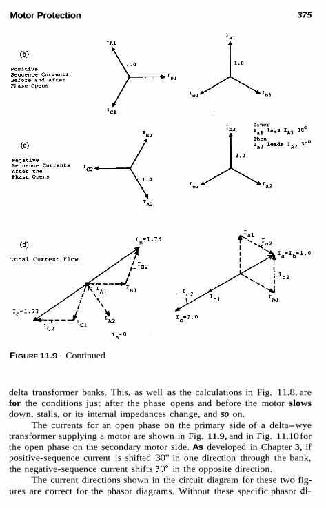
Motor Protection 375
FIGURE 11.9 Continued
delta transformer banks. This, as well as the calculations in Fig. 11.8, are for the conditions just after the phase opens and before the motor slows down, stalls, or its internal impedances change, and so on.
The currents for an open phase on the primary side of a delta-wye transformer supplying a motor are shown in Fig. 11.9, and in Fig. 11.10 for the open phase on the secondary motor side. As developed in Chapter 3, if positive-sequence current is shifted 30" in one direction through the bank, the negative-sequence current shifts 30' in the opposite direction.
The current directions shown in the circuit diagram for these two fig- ures are correct for the phasor diagrams. Without these specific phasor di-

376 Chapter 11
agrams, the I8 in Fig. 11.9 could be shown into the motor as indicated, but at magnitude with Zc at ~ flowing to the source. This is actually the flow, and is indicated in Fig. 11.9 by the phasor diagram, showing that 1" flows as indicated, but Ic is 180' from Z,, both at magnitude. If I" and Z, were shown in opposite directions in the circuit diagram, the correct phasor diagram would be to show ZB and Ic in phase. These currents can be traced through the transformer with the unbalances shown, remembering that 1.0-pu current in the wye winding appears as 0,577-pu current in the delta winding.
Negative-sequence voltage can be used to detect unbalance in motor circuits. By fundamental definition V, = -12Z,. With reference to the ex- ample of Fig. 11.8, the per unit negative-sequence voltages on the two sides
(4 Transformer Source Open Phase
1.u >' ,Igi A positive currents (b) 5eqYenCe
Before and Afrer Phase Opens
ICI Ic 1 lbl
FIGURE 11.10 (a) Unbalanced current flow through a delta-wye transformer bank to a motor for phase A open on the motor or secondary side: (b) positive- sequence currents before and after phase opens: (c) negative-sequence cur- rents after phase opens: (d) total current flow.

Motor Protection
Since @) Negative sequence leads Ial currents
After the Phase Opens by 30° then
by 30° Ia2 lags Ia2
377
Yb2 of the open phase for situations a and b follow. For situation c, V, = V,, because there is no open phase between the supply and the motor.
Case a Case h
V, = 0.96 X 0.05 = 0.048 V,, = 0.96 X 0.15 = 0.144
1.6 X 0.05 = 0.08 1.5 X 0.15 = 0.227
When the open phase is downstream or between the V, measurement and the motor, the negative-sequence voltage relay will “see” V,, which can be quite low because of the low impedance source. When the open phase is upstream or between the V, measurement and the supply, the relay will “see” Vm, which is generally larger. Thus negative-sequence voltage is most useful for upstream open phases, with phase-current comparison for the downstream ones.

378 Chapter 11
11.12 UNBALANCE AND PHASE ROTATION PROTECTION
As suggested in Section 11.11, there are several handles available for un- balance detection: (1) magnitude differences between the three-phase cur- rents, (2) the presence of negative-sequence current, and (3) the presence of negative-sequence voltage. All three of these are used for protection.
The current balance-type (46) compares the phase current magnitudes and operates when one phase current is significantly different in magnitude from either of the other two phase currents. This is very effective protection for individual motor feeders to detect open phases or unbalances in that circuit. If other loads are supplied by the circuit to which this protection is connected, care should be taken to ensure that any open phase or unbalance will not he camouflaged by the balanced current to the sound load. One relay should he applied for each load or feeder. The typical minimum sen- sitivity of these relays is about 1 A in one phase with zero current in the other, or 1.5 pu in one phase and 1 pu in the other.
Another type (46) responds to the negative-sequence current, either instantaneously with a fixed time delay added, or following the l i t = K char- acteristic, as used for generator protection. These types of relays are not widely applied for motor protection.
The negative-sequence voltage type (47) is recommended to detect phase unbalance and phase reversal in the supply or source circuits. Typical operating sensitivities are about 0.05 pu V,. One such relay should be con- nected through VTs (either wye-wye or open-delta VTs) to each secondary supply bus. As shown in Section 11.11, sufficient V, voltage generally is available for open phase in the source or upstream system. They should not be applied for open-phase downstream or between the relay and motor, for as shown, this V, voltage may be quite low.
When the phases are reversed, 1 pu V , becomes 1 pu V,, so the negative-sequence relay positively responds to phase reversals. Phase- reversal relays also are available equivalent to a small motor. Normal phase rotation produces restraint or contact-opening torque, while phase reversal causes operation or contact-closing torque.
11.13 UNDERVOLTAGE PROTECTION
Low voltage on a motor results in high current and either failure to start, to reach rated speed, or to lose speed and perhaps pull out. Very often, protec- tion for undervoltage is included as part of the motor starter, but an inverse time undervoltage relay (27) is recommended to trip when prolonged un- dervoltage exists and as backup.

Motor Protection 379
11.14 BUS TRANSFER AND RECLOSING
When motors, either induction or synchronous, are reenergized before they have stopped rotating, high transient torques can result, with possible dam- age or destruction. This can occur when a rapid transfer of motors is made from a bus that has lost voltage to a live auxiliary bus. Such transfers are necessary to maintain vital services to the auxiliaries supplying large gen- erating plants or to critical industrial processes.
Another example is industrial plants supplied by a single-utility tie. Problems in the utility will require opening the tie. Most experience indicates that many faults in the utility are transient, resulting from lightning induc- tion, wind, or tree contacts. As the utility is anxious to restore service promptly to its customers, they frequently use high-speed reclosing (about 0.20-0.60 s), and thus reenergize the motors, with possible damage.
The safe limits for reconnection of motors are complex and beyond this chapter’s scope. If rapid transfer is mandatory, special attention should be given to this during the design stage. Otherwise, the best policy is either to delay an reclosure or reenergize induction motors, or to ensure that the motors are quickly disconnected from the system. For induction motors, reenergization should not occur until the motor voltage has dropped to 33% or less of normal.
For synchronous motors, reclosing or reenergizing must not be per- mitted until proper resynchronization can be effected. This means opening the motor supply promptly on the loss of supply.
An effective means to open the supply breaker under these conditions is the application of an underfrequency relay. Typical underfrequency relay (81) settings would be 98-97% of rated, with time to override the momen- tary voltage dip effects, but before reenergization can take place. If the plant has local generation, or there are other ties with generation of the supply feeder, care should be taken to ensure that the frequency will decline on loss of the utility. Generation sufficient to maintain load, particularly at light- load periods, will result in negligible frequency change.
11.15 REPETITIVE STARTS AND JOGGING PROTECTION
Starting motors repetitively with insufficient time between, or operating them with extreme load variations (jogging), can result in high motor tempera- tures. It is possible for a high temperature to follow a shorr-time load peak with subsequent low-current load in normal operation and not exceed the motor limits. Thermistors on smaller motors and an integrating thermal over- load unit responding to total heating [see Eq. (11.13)] for larger motors

380 Chapter 11
provide a means of protection. Relays (49) operating on both overcurrent and temperature have been used. They operate with high current and high temperature. A high temperature without overload or a high overload without high temperature may not cause operation. Application of these requires careful analysis of the motor. Again the microprocessor units can monitor this effectively.
11 .I6 MULTIFUNCTION MICROPROCESSOR MOTOR PROTECTION UNITS
Microprocessor motor protection units combine the various protection tech- niques for motor protection, as covered earlier, along with control, data collection, and reporting (either locally or remote), and self-diagnostic fea- tures. The basic protection is essentially the same as has been provided over many years with individual relays. Thermal protection using thermal replica or RTD type relays has been the most imprecise area, and the microprocessor units offer significant improvement. However, it should always he remem- bered that although microprocessors are very accurate, thermal limits are not precise. Designers can provide safe- or dangerous-operating zones, hut i t is difficult to supply a single curve as engineers desire and demand.
The microprocessor unit establishes electrical, thermal, and mechanical models that are derived from the input current, voltage, manufacturers motor data, and optionally RTDs within the motor. These models are used in the microprocessor algorithms to provide protection that is modified with time.
11 .I7 SYNCHRONOUS MOTOR PROTECTION
The protection discussed in the foregoing for induction motor protection is applicable to synchronous motors, with additional protection for the field and for asynchronous operation. These motors usually include control and protection for starting, field application, and synchronizing. In addition, the following protection should be applied or considered.
As illustrated in Fig. 8.16, reduction or loss of excitation requires re- active power from the power system; thus, lagging current flows into the motor. For small units, a power factor relay (55) is recommended. This relay operates when current into the motor lags more than 30". Typical maximum current sensitivity occurs when the current lags 120", so a fairly large current is required for typical loss of field lagging currents of 30-90". For large synchronous motors, distance loss-of-field relays, as described for genera- tors, are recommended (see Sec. 8.11). This provides improved protection for partial loss of field in addition to complete loss.

Motor Protection 381
alternate to 50G Ct
Differential ach-e of Figure 11.311
applicable
Notes: 1. The circles indicate functions that may be packaged individually or in various different conbinstions.
2. Additional proreceion for Synchronous motor5 covered in section 11.16.
3. Protection to avoid re-energizarion after short-time interruptions covered in Section 11 .14 .
FIGURE 11.11 Typical recommendations for motor protection: (a) for motors without neutral leads and RTDs available; (b) for motors with neutral leads and RTDs available.

382 Chapter 11
Out-of-step protection may or may not he required, depending on the system and motor. Faults in the system that momentarily reduce the motor voltage may cause the voltage angles between the system and motor to swing apart sufficiently that, on fault clearing, the motor cannot recover and so will go out of step.
If the motor is running synchronously, only dc voltage exists in the field or exciter windings. When it falls out of step from system disturbances or loss of field, ac voltage appears that can be used to detect these conditions if the machine has brushes. With modem brushless exciters, the power factor relay (55) will provide both pullout and loss-of-field protection.
11.18 SUMMARY TYPICAL PROTECTION FOR MOTORS
Typical protection recommended and commonly applied for the protection of motors is summarized in Fig. 11.11. The application of the various relays is covered in the foregoing. These are general recommendations, recognizing that any specific application may use more or less depending on local cir- cumstances, economics, and individual preferences.
BIBLIOGRAPHY
See the Bibliography at the end of Chapter 1 for additional information. ANSIilEEE Standard C37.96, Guide for AC Motor Protection, IEEE Service Center. Brighton, R. J., Jr. and P. N. Ranade, Why overload rclays do not always protect
motors, IEEE Trans. Ind. Appl., IA 18, Nov.-Dec. 1982, pp. 691-697. Dunki-Jacobs, J. R. and R. H. Ker, A quantitative analysis of grouped single-phased
induction motors, IEEE Trans. Ind. Appl., IA 17, Mar.-Apr. 1981, pp. 125-132. Gill, J. D., Transfer of motor loads between out-of-phase sources, IEEE Trans. Ind.
Appl., IA 15, July-Aug. 1979, pp. 376-381; discussion in IA 16, Jan.-Feb. 1980, pp. 161-162.
Lazar, I., Protective relaying for motors, Power Eng., 82, No. 9, 1978, pp. 66-69. Linders, J. R., Effects of power supply variations on AC motor characteristics. IEEE
Trans. Ind. Appl., IA 8, July-Aug. 1972, pp. 383-400. Regotti, A. A. and J. D. Russell, Jr., Thermal limit cuwes for large squirrel cage
induction motors, IEEE Joint Power Generation Conference, Sept. 1976. Shulman, J. M., W. A. Elmore, and K. D. Bailey, Motor starting protection by
impedance sensing, IEEE Trans. Power Appar Syst, PS 97, 1978, pp. 1689- 1695.
Woll, R. E., Effect of unbalanced voltage on the operation of polyphase induction motors, IEEE Trans. Ind. Appl., Jan.-Feb. 1975, pp. 38-42.

12 Line Protection
12.1
Lines provide the links-the connections-between the various parts of the power system and the associated equipment. Power generated at low volt- ages is stepped up to higher voltages for transmission to various stations, where it is stepped down for distribution to industrial, commercial, and res- idential users.
Most power systems have from two to many voltage levels. Over the 100-year history of ac systems, the actual three-phase voltages used have varied considerably, with no international standards. In the United States, the IEEE Standards Board adopted a set of standards in 1975 proposed by the Industrial Applications Society. These are summarized in Table 12.1. The class designations are not completely or uniformly agreed on between the IEEE Power Engineering Society and the Industrial Application Society, both of whom are involved in power systems. Within the power utility area, there has been, and continues to be, a general understanding of voltage classes as follows:
CLASSIFICATION OF LINES AND FEEDERS
Industrial: distribution 34.5 kV and lower Subtransmission 34.5-138 kV Transmission 115 kV and higher
383

TABLE 12.1 ANSVIEEE Classifications of Three-Phase Power System Voltages
IAS'
Nominal rms line-to-linea system voltage
Three-wire systems Four-wire systems
Optional or Ootional or Maximum
PES" Preferred existing Preferred existing voltage
Low No voltage 208Y/l20
48OYl277 class stated 240 24011 20 Tap (ANSI 480 C84.1) 600
Medium 2,400
4,800 6,900
(LV)
4,160 41,66OY/2,400 (MY
12,47OY/7,200 13,2OOY/7,620
13,800
23,000 24,94OY/14,400
34,500 34,5OOY/19,920
220Y/l27 245/127 508Y/293 635
2,540 4,4OOY/2,540 5,080 7,260
8,32OY/4,800 8.800Y/5.080 12,OOOY/6,930 12,7OOY/7,330
13,2OOY/7,620 13,97OY/8,070
13,800\(/7,970 14,520Y/8.380 20,78OY/12,000 22,OOOY/12,700 22,86OY/l3,200 24,2OOY/13,970
28,4OOY/15,240 36,51OY/21,080 N
24,340 P

High (HV)
Extra- high (EHV)
high ( V W
Ultra-
46 kV Higher voltage (ANSI 69 kV C84.1) 115 kV
138 kV
230 kV ANSI 345 kV
C92.2 500 kV 765 kV
1,100 kV
161 kV
r: 48.3 kV a 72.5 kV m 121 kV 9 s 145 kV m 169 kV 2
5 242 kV a 362 kV 550 kV 800 kV
1,200 kV
*The second voltage for the three-phase four-wire systems is line to neutral or a voltage tap, as indicated. ?AS: IEEE Industrial Applications Society. Their voltage class designations adapted by IEEE Standards Board (LB 1aaA) 'PES: IEEE Power Engineering Society. Standard references indicated in the table. Source: IEEE Standard Dictionary.

386 Chapter 12
with the last class generally divided into:
High voltage (HV) 115-230 kV Extrahigh voltage (EHV) 345-765 kV Ultrahigh voltage (UHV)
As indicated, these are not well defined, so the range can vary some- what in any specific power system. With time, more conformity with the standards will take place, but there exist many different and nonstandard voltages in use that were adopted many years ago and will not be changed for a long time. Some of these, but not all, are indicated in the table as optional or existing.
The voltage values indicated represent the nominal and typical rms system voltages (line-to-line unless so indicated) commonly designated in technical information and communication. As power flows through a system the actual voltage varies from point to point from the generators to the ultimate terminals from the drops, transformer ratios, taps, regulators, ca- pacitor banks, and so on; hence, arbitrary nominal or typical values are selected as indicated.
The terminals of the lines and feeders and the location of equipment, such as transformers, generators, and circuit breakers, are known as stations, plants, and substations. The specific designation is neither well defined nor standardized. A generating station or plant is obvious. Asubstation is smaller and less important than a station. In one system relative to another, a station in one might be designated as a substation in the other, and vice versa. So common designations are generating stations, switching stations, power sta- tions, substations, distribution stations, and so on.
Many lines are two-terminal, but there are a number of multiterminal lines with three or more terminals. These may interconnect stations or sub- stations, but frequently, are taps to supply loads. Thus, lines of all voltage levels can become distribution circuits. When an industrial or commercial complex with a large load requirement is located near a transmission line, it often becomes economical to tap the line. Distribution lines usually have many taps, either three-phase or single-phase, as they supply loads along their routes.
Three-phase line angles vary with the type, size of the conductors, and spacings. Typical ranges for different voltages are as follows;
1000 kV and higher
kV Angles
7.2-23 25"-45" 23-69 45"-75" 69-230 6n0-8n- 230 UD 75"-85"
~ __

Line Protection 387
12.2 LINE CLASSIFICATIONS FOR PROTECTION
For protection purposes lines in this book are classified as 1. Radial or feeders: These have a positive-sequence source at only
one terminal. Typically, they are distribution lines supplying power to non- synchronous loads. As indicaied in Section 4.8, induciion motors are usually not considered as sources. For faulis on the line, current to the fault is only from this source end. With both ends grounded and a ground fault on the line, current can flow from both ends, but tripping the positive-sequence source end deenergizes the fault. However, zero-sequence mutual coupling from an adjacent line(s) can continue the ground fault; therefore, the ground sources must be tripped.
2. Loop lines are those with positive-sequence sources at two or more ends. In general, these are all types of transmission lines and can include distribution circuits. Fault current to the line faults is supplied from these source terminals, and all source terminals must be tripped for both phase and ground faults. Power systems in the United States are generally multi- grounded; thus, positive-, negative-, and zero-sequence currents can flow to ihe line faults. If one end of the two-terminal line is ungrounded, then the line is a loop for phase faults, but a radial for ground faults. Again mutual transmission from parallel lines can induce significant zero-sequence into the line. The effect is covered later i n this chapter.
12.3 TECHNIQUES AND EQUIPMENT FOR LINE PROTECTION
The relay protection techniques available for all l h e protection includes the following:
1. Nondirectional instantaneous overcurrent 2. Nondirectional inverse-time-overcurrent 3. Direciional instantaneous overcurrent 4. Directional inverse-time-overcurrent 5. Current balance 6. 7.
Directional distance-instanianeous or step or inverse-time Pilot wiih a wmmunication channel between terminals (see Chap. 13)
All of these are employed individually or in various combinations for both phase and ground protection of lines. These relay types are discussed in Chapter 6 and their applications are covered in the present chapter. The current-balance type compares the currents in parallel lines to detect an

388 Chapter 12
unbalance resulting from a fault in one line. It is not in general use in the United States. This is because it is not applicable to single lines; it must be disabled for single-line operation; it requires interconnections between the controls for the two lines, which is not desirable for operation and testing; and it can experience difficulties for a fault involving both paralleled lines.
Circuit breakers are ubiquitous in power systems, but in the distribu- tion areas, fuses, reclosers, and sectionalizers are in common use. A brief review of these follows:
12.3.1 Fuses The continuous, rated current of the fuse must be equal to or greater than the maximum short-time load that will pass through it. Also, the symmet- rical-interrupting rating of the fuse should be equal to or greater than the maximum fault current. Attention must be given to system voltage and in- sulation level and the system XlR ratio. Fuses operate in a time-current band between maximum-clearing times and minimum melt (or damage) times. The difference is the arcing time within the fuse.
The minimum melt time is important when the fuse backs up or over- reaches other devices. The latter devices must clear the fault before thermal damage can occur to the fuse, as is indicated by the minimum melt time.
12.3.2 Automatic Circuit Reclosers
Commonly known as reclosers, these are a type of circuit interrupters with self-contained controls to sense overcurrent and open on faults, either in- stantaneously or with the time-delay. They can be programmed to initiate automatic reenergization of the circuit (reclosing) at variable intervals if the fault persists, and eventually to lock out.
Three-phase reclosers have both phase and ground units. Single-phase reclosers cannot have ground sensors, but rather, they rely on the phase unit for line-to-neutral or line-to-ground faults involving the phase to which they are connected.
Single-phase reclosers for single phase taps can be used on three-phase feeders. The advantage is that service can be maintained on the unfaulted phases. However, three-phase reclosers are generally recommended to avoid single-phasing three-phase motors and potential ferroresonance, as discussed in Section 7.9.
Reclosers are used because their cost is generally less than conven- tional breakers and separate relays.

Line Protection 389
12.3.3 Sectionalizers
A circuit-isolating mechanism that is not rated to interrupt fault current is a sectionalizer. It opens while deenergized after sensing a preset number of downstream faults. It is manually reset.
12.3.4 Coordinating Time Interval
The coordinating time interval (CTI) is the time interval between the oper- ation of protection devices at a near station and the protection devices at a remote station for remote faults that the near station devices overreach. Thus, for these remote faults, the near-station devices’ operating times must not be less than the remote devices’ operating time plus the CTI. Faults On the remote line should be cleared by the remote protection device and backed up by the near-station devices. This is illustrated in Fig. 12.1.
The CTI consists of
1.
2.
Breaker fault-interruption or fault-clearing time, typically two to eight cycles (0.033-0.133 s). Relay overtravel (impulse) time: The energy stored in the electro- mechanical induction disk or solid-state circuitry will continue op- eration after the initiating energy is removed. Typically, this is not more than 0.03-0.06 s for electromechanical units; less, but not zero, for solid-state units. Safety margin for errors or differences in equipment-operating time, fault current magnitudes, CT ratios, and so on.
3.
The CTI values frequently used in relay coordination range between 0.2 and 0.5 s, depending on the degree of confidence or the conservatism of the protection engineer-0.3 s, is frequently used.
12.4 COORDINATION FUNDAMENTALS AND GENERAL SETTING CRITERIA
The “protection problem” was outlined in Section 6.3 (see Fig. 6.5). This time solution applies to lines, for the protection can extend into adjacent lines, buses, transformers, motors, and so on. The settings must ensure that the phase and ground protections do not operate in these overlapping (backup) areas until the primary phase and ground protections assigned to that area have the opportunity to clear the fault. Setting of the protection equipment to ensure this is selective setting or coordination. Figure 12.1 illustrates coordination on loop-type lines. Coordination on feeders or radial lines is the same, except only in one direction: from the power source to the loads.

390
181
I
Chapter 12
Prlmarg Protectlo" zone for Relays ar H. Breaker 7. t
I C I G H 5
GI
d2 & GI 16 I I "1 S1
"2 5 2
I C I G H 5
GI
d2 & GI 16 I I "1 S1
"2 5 2
FIGURE 12.1 Protection zones, fault data requirements and time coordination curves for typical loop-type lines. For distribution, radial lines, current flows only in one direction; hence, protection zones, fault data, and time coordi- nation curves are required for only one direction: (a) The key comments for setting relay at G for breaker 5 to protect time GH; (b) coordination with directional inverse-time-overcurrent relays; (c) coordination with directional distance units.
Line Protection 391
The objective is to set the protection to operate as fast as possible for faults in the primary zone, yet delay sufficiently for faults in the backup zones. As in Fig. 6.4 the settings must be below the minimum fault current for which they should operate, but not operate on all normal and tolerable conditions. Occasionally, these requirements provide very narrow margins or no margins. This is especially true in loop-type lines, for which there can be a large variation in fault magnitudes with system operation. Fault currents can be high at peak-load periods with all the generation and lines in service, but quite low as equipment is removed during light-load periods. The fault study should document these extremes. When coordination is not possible, either a compromise must be made or pilot protection (see Chap. 13) applied. Thus, coordination is a “cut-and-try” process.
Although today many computer programs exist for coordinating equip- ment, it is still important for protection engineers to understand this process.
12.4.1 Phase Time-Overcurrent Relay Setting
For lines, there is rarely a thermal limit as there was for transformers. The minimum-operating current (relay pickup) must be set so that operation will not occur on the largest transient or short-time current that can be tolerated by the system. The key factors to be considered are
1. Short-time maximum load (fs,.%,): This is the current that the circuit may be required to carry during emergencies or unusual operating conditions for intervals that can be from about 1 h or more. Prac- tically, it is often the maximum capability of the transformer or maximum limit of the load. Magnetizing inrush of the transformers supplied by the circuit: Where overcurrent type relays are applied, the inrush often is not too severe, or it decays rapidly because of the appreciable amount of resistance in the circuit.
2.
12.4.2 Ground Time-Overcurrent Relay Setting
The minimum-operating current (pickup) must be set above the maximum zero-sequence current unbalance that may exist and can be tolerated by the system. This unbalance is usually the result of unequal loading of single- phase taps between the three phases. Monitoring the unbalance and changing taps are used to keep the unbalance minimum. With this, and except for problems in coordinating with fuses, ground relays can be set much lower than the phase relays for increased fault sensitivity.
Typically, 0.5- and 1.0-A taps are used where the unbalance is low, especially at the higher-voltage levels.

392 Chapter 12
12.4.3 Phase and Ground Instantaneous Overcurrent Relay Setting
Instantaneous overcurrent (IT) units operate with no intentional time delay and generally on the order of 0.015-0.05 s. This requires that they be set not to overreach any other protective device. An exception is for “fuse- saving,” discussed later.
The fundamental principles for setting the instantaneous units with reference to Fig. 12.1, breaker 5 at bus G, are:
1. Set at W,. bus m ~ X ((rmn, in the figure). If there is a tap or a recloser before the far bus, use the maximum current at that device or point. k is typically 1.1-1.3. The value depends on the responses of the IT unit to a possible fully offset current and the degree of conservatism of the protection engineer. If this setting value current is greater than the maximum near-bus fault (see Ih in Fig. 12.1), a nondirectional instantaneous unit can he used. If this setting value current is less than the maximum near-bus fault (see IN in Fig. 12.1), a directional instantaneous overcurrent unit is required, or the IT setting must be increased to avoid op- eration with a nondirectional type.
2.
3.
On feeders or radial lines, only criterion 1 applies. Criteria 2 and 3 are not applicable, because there is no current for faults behind the protection device.
Cold load is a short-time increase in load current that occur when a distribution feeder is reenergized after an outage. Normal feeder load is based on diversity, because not all customers require maximum load at the same time. After an outage, this diversity is lost momentarily, because all of the load is energized at the same time. The amount and duration is quite variable, depending on the circuit and the length of the outage, so experience history is usually necessary to document this.
A phase-overcurrent relay pickup of 1.25-1.5 times the maximum short-time load or greater will be required to avoid operation on short-time transients with inverse relay characteristics. The lower multiples can be used with the extremely or very inverse types, as the operating times arc very long just above pickup. The transient overcurrents may energize the relays but subside below relay pickup before the operating time is reached. Gen- erally, the extremely inverse characteristics more nearly match the fuse char- acteristics and motor-starting curves, so are preferable for protection in the load areas. Moving back toward the source, the less inverse types are applicable.
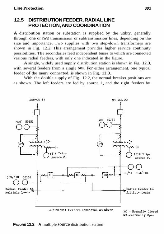
Line Protection 393
12.5 DISTRIBUTION FEEDER, RADIAL LINE PROTECTION, AND COORDINATION
A distribution station or substation is supplied by the utility, generally through one or two transmission or subtransmission lines, depending on the size and importance. Two supplies with two step-down transformers are shown in Fig. 12.2. This arrangement provides higher service continuity possibilities. The secondaries feed independent buses to which are connected various radial feeders, with only one indicated in the figure.
A single, widely used supply distribution station is shown in Fig. 12.3, with several feeders from a single bus. For either arrangement, one typical feeder of the many connected, is shown in Fig. 12.3.
With the double supply of Fig. 12.2, the normal breaker positions are as shown. The left feeders are fed by source 1, and the right feeders by
SOURCE #1
50N 50151
source #1
50N 50151
II
1518 Trips source #2
iOl51 501/5lN 50N151N 50151
Radial Feeder to Radial Feeder to Multiple Load*< 'hltiple Loads
-
NC = Normally Closed SO =Normally Open
Allditional Feeders connectee as abare
FIGURE 12.2 A multiple source distribution station

394 Chapter 12
1 n u 'Other Similar Load P
r? Feeders
SOVRCE - 4
3 6
M W L o a d w 1 A
50151 5 50N151N 2
Load S Load M
RELAYS AT THE SOURCE STATION: Primary Protection Zones;
Betveen the breaher, the fuse to Load M and to the recloser R. Backup zone;
Betueen load M fuse and load M bus (not s h o w ) Betveen recloser R to the fwes P, S and W
RECLOSER R: primary zone; Betveen recloser and the fUS4s at loads P, S, and W
Baekup zones;
prirnary pP0tectio" zones;
Between the fuses at P, S, W and their respective load buses (not shavn) FUSES AT THE YARIOUS h3ADS:
Betueen the load fuses and the respective load b u e w ínor shoun) Backup zanes; Betveen the iespective load buaes and the loads ( m t ehornl
FIGURE 12.3 Protection zones lor a typical distribution feeder
source 2, with the NO hreaker between them. With one source or one trans- former out of service, say 2, the right station load can he carried hy 1 by opening all the right NC breakers and closing all the NO hreakers. This is added load on the source 1 ttansformer, so therefore, the rating can be increased hy forced air and oil comhinations as required.
The CTs are interconnected, as shown, to provide fault current in only the faulted feeder and zero in the unfaulted feeder for either two- or one- source operation.
The differential is shown around the transformers, but this could he extended to the high-side hreaker if located at the transformer. The 87, high- side 50/51, 51N, and the neutra1 151N relays, all trip the high-side either directly or hy transfer trip, depcnding on the high-side disconnection means available.
Additional service continuity may he obtained by interconnecting a feeder off of one hus to a feeder off the other hus through a normally open recloser somewhere out on the lines. With a loss of supply to one of the feeders, this NO recloser will close in an attempt to pick up the load. Should
Line Protection 395
there still be a fault on this feeder the recloser will trip and lock out. This tie recloser is not shown in the figures.
Many times fault currents at the distribution secondary levels are de- termined essentially by the substation transformer and feeder impedances, the source impedances of the large power system often being very small and practically negligible. Thus, fault levels are relatively constant with system changes except for fault resistance. This latter situation is quite variable and can be very high to “infinite,” especially for downed conductors that d o not make contact or that have only a high-resistance contact to ground.
Fuses are widely used for phase and ground protection. However, they receive only phase or line current, whereas ground relays operate on 31,) neutral current. Fortunately, fuses are applied to radial or feeder circuits where the line current equals 31, (tor a phase-a-to-ground fault, I, = 31<,). Note, this is not true for loop lines. Thus, coordination of ground relays with fuses can require ground relay settings essentially equivalent to the phase relays. High ground relay settings can also result from high zero- sequence load unbalance by unequal phase-to-neutral or phase-to-ground loading.
Many distribution systems are four-wire multigrounded. Consequently, a neutral (fourth wire in three-phase distribution) is tied to the substation transformer ground(s) and carried along with the feeder phase(s). This is tied to ground at each pole. Faults at the pole are generally phase-to-neutral, whereas faults out on the line are probably phase-to-ground. In either situ- ation most of the return current will flow in the neutral wire because it is nearer the phases; hence, a lower inductance. Therefore, at the grounded station transformer-neutral, most of the return is by the neutral, rather than through the ground. Connecting the neutral ground relay between ground and the neutral wire connection will essentially provide 31,, fault current, but this can be very small, especially for remote feeder faults. Connection of the ground relay between the transformer-neutral and the neutral (fourth). wire connection measures the total load unbalance and fault current. This can require a high ground relay setting unless thc loading is carefully monitored.
Because the required ground relay setting may be essentially the same as the phase relays, the tendency is to omit the ground relays. This may not be desirable in liability cases for which the absence of ground relay may suggest inadequate protection.
The protection zones for a typical distribution feeder are outlined in Fig. 12.3. The coordination of the various devices where the fault current is the same or related by the transformer connections is done conveniently by overlaying time-current characteristics available on transparent log-log pa- per. These can be shifted until proper coordination between the various de-

396 Chapter 12
vices is obtained. This method was used for transformer overload protection examples in Chapter 9, and in Fig. 12.5 in the following example.
12.6 EXAMPLE: COORDINATION FOR A TYPICAL DISTRIBUTION FEEDER
A typical 13-kV feeder of several lines at a distribution substation is shown in Fig. 12.4. This is supplied from a 115-kV line through a 15/20/25-MVA transformer protected by a high-side fuse. Only one of the four feeders is illustrated and is typical, with the loading and protection of the other feeders similar, but different, The fault values are in amperes at 13.09 kV for solid faults at the locations shown.
If we begin at the high-side fuse, the setting and coordination of the protection is as follows: The maximum load for the 25-MVA tap is
25,000 6 X 115 = 125.5 A at 115 kV
A 125E fuse was selected for the transformer bank primary. Its operating
115kV system 4340MVASc
Load
FIGURE 12.4 Typical distribution feeder serving multiple load centers
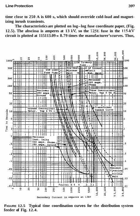
Line Protection 397
time close to 250 A is 600 s, which should override cold-load and magnet- izing inrush transients.
The characteristics are plotted on log-log fuse coordinate paper, (Fig. 12.5). The abscissa is amperes at 13 kV, so the 125E fuse in the 115-kV circuit is plotted at 115113.09 = 8.79 times the manufacturer’s curves. Thus,
y 1 0 _I A n
Secondary Current in iMpereS at 13kV
FIGURE 12.5 Typical time coordination curves for the distribution system feeder of Fig. 12.4.

398 Chapter 12
the 600-s minimum melt current of 250 A becomes 250 X 8.79 = 2196 A for balanced currents. The dashed-line minimum-melt curve, shown to the left, reflects the effect of load current preheating the fuse.
Whereas phase-to-phase faults on the 13-kV side are 0.866 of the three-phase fault value (see Fig. 9.20), the current in one phase on the pri- mary is the same as the three-phase fault value. However, the primary fuse sees only 0.577 of the secondary one-per-unit current for 13-kV phase-to- ground faults (see Fig. 9.20). The dashed-line curve to the right is the pri- mary fuse minimum-melt characteristic for secondary ground faults. For the 600-s-operating time, 2196 X ~ = 3804 A is equivalent to 2196 A for a phase-to-ground fault.
The transformer through-fault overcurrent limit curve is plotted as shown. This area is discussed in Chapter 9. As shown, the transformer is protected satisfactorily against thermal damage.
The 65T and lOOT fuses selected on the basis of the loads served from the taps are shown plotted on Fig. 12.5 from manufacturer’s curves. The left curve is minimum melt, the right maximum clearing.
The maximum load through the recloser is 230 A. A recloser was selected with a minimum trip rating of 560-A phase, slightly more than twice the load needed to override cold load with a safety factor. The ground unit is set at 280 A by choice. The time characteristics for both units are plotted for the timed and the instantaneous operations from the manufacturer’s data.
The maximum load through the breaker and relays at the 13-kV bus is 330 A. Thus, the CT ratio of 4005 will give a secondary current of 3301 80 = 4.13 A.
Extremely inverse time-overcurrent relays provide good coordination with the fuses and the recloser. Selecting tap 9 provides a phase relay pickup of 9 X 80 = 720 A, just over twice the maximum load needed to override a cold load. The ground relay is set on tap 4 by choice. This provides a primary 13-kV pickup of 4 X 80 = 320 A. Time settings for the phase and ground relay provide a CTI of at least 0.2 s above the recloser. This is satisfactory when the recloser time curves include fault-interruption time.
Fast, instantaneous tripping with reclosing is very useful because ap- proximately some 80-95% of faults on open-wire circuits are temporary. They are caused primarily by momentary tree contact from wind, or they may be lightning-induced. Frequently, these faults can be cleared and service restored quickly by deenergizing the line with immediate rcclosing.
To provide this instantaneous tripping, phase and ground units can he applied to breakers to supplement the time units. Reclosers have either a fast or slow time-current characteristic, of which only one at a time can be used. Several attempts can be made, usually one to three. The particular number and sequence is based on many local factors and experience.

Line Protection 399
With reference to Fig. 12.4, when using k = 1.2, the instantaneous unit is set to not operate for fault 2 or the phase at 7357 A and the ground at 6990 A. This is not shown on Fig. 12.5, but would be a horizontal line at the relay, plus breaker clearing time to the right from the foregoing operating values. In this application, the operating values do not provide a large margin over the maximum fault values for fault 1; hence, only a short section of the line has instantaneous protection. This is still recommended, for it pro- vides fast clearing for the heavy close-in faults.
“Fuse-saving” is used to avoid fuse operations for transient faults and, thereby, avoid long outages for crews to replace them. This is accomplished by a second instantaneous unit set to overreach the fuse and, one hopes, to clear transient faults before the fuse can operate. An instantaneous reclose is attempted and, if successful, service is restored. The instantaneous unit is locked out, thereby permitting the fuse to clear a continuing fault. An in- dustry survey by the IEEE showed that 81% use this for phase faults and 61% for ground faults.
Thus, for fuse-saving at the breaker in Fig. 12.4, the instantaneous units could be set to operate for fault 2, hut not for fault 3, or at 5374-A phase, 4763-A ground (1.2 X fault 3). However, it is important that the instantaneous unit and breaker clear faults before the fuse is damaged (min- imum melt) or blown. Figure 12.4 shows that the lO0T fuse will be damaged at about 5000 A after about 0.03 s (1.8 cycles at 60 Hz). Thus, the fuse will blow before the breaker opens; therefore fuse saving is not applicable at the breaker.
Fuse-saving is applicable at the recloser when operating on its fast or instantaneous curves. For faults on the laterals beyond faults 4, 5, or 6, the recloser will trip and reclose once or twice as programmcd. If the fault is transient and cleared, service will be restored without a fuse operation. After this the recloser operates on its slow curves, and the fault is cleared by the proper fuse on the laterals or by the recloser for faults on the feeder.
A sectionalizer could be used for the fault 2 lateral circuit instead of the fuse. It would opcn during a deal period to clear a permanent fault on its circuit after, say, two unsuccessful fault operations by the breaker instan- taneous units.
Reclosing can provide a potential liability where the circuit can he physically contacted by persons, such as downed lines at or near ground level. Many years ago a case was reported where a conductor fell on a pile of lumber and started a small fire. When the power company arrived at the scene they were very surprised to find the wire coiled on the ground near the lumber, but no victim. It appeared that a helpful passer-by had moved the conductor during the dead period between the reclosing cycle. Most fortunate, but very risky.

400 Chapter 12
12.7 INDEPENDENT POWER PRODUCER, DSGs, AND OTHER SOURCES CONNECTED TO DISTRIBUTION LINES
Such power sources are being tied to distribution systems to supply power to the utilities. This area was discussed in Chapter 8, primarily from the generator perspective.
With the possibility of current for line faults supplied from both the DSG and the utility, the radial line tends to become a loop type for which directional relays should be used. For Fig. 12.4, suppose a DSG is connected to the feeder circuit shown. A problem then is for a fault on an adjacent feeder. The DSG supplies current to the fault through the feeder and its nondirectional overcurrent to the overcurrent relays on the adjacent feeder. The possibility exists that both the unfaulted DSG and the faulted feeder may trip.
However, practically the DSG contribution is often quite small when compared with that from the utility. The large utility contribution requires a high setting, with very inverse-time-current relay characteristics generally used, the operating time for the low DSG contribution through its feeder is very long. Hence, directional-type relays may not be required.
It is mandatory, as emphasized in Chapter 8 and again here, that all nonutility-owned power sources be promptly disconnected from the utility whenever there is an interruption between the utility and nonutility sources. This can be accomplished by undervoltage (27), ovcrvoltage (59), under- and overfrequency (81/U, 81/0) relays at the nonutility units. lnstantancous tripping on overvoltages greater than about 125% of rated should he pro- vided where high voltages can occur, because of ferroresonance in an iso- lated island that includes a nonutility source.
If the utility and its ground source can be separated from an un- grounded DSG, the DSG and connected system can operate in an un- grounded mode. A 59N relay connected across the wye-grounded-broken- delta should be used for protection.
When a DSG can become islanded with part of the utility system for which it could supply the load, some method of remote tripping of the DSG is required. One reason, among many cited in Chapter 8, is that the utility cannot restore its service without potential damage to the DSG and con- nected customers.
Instantaneous, automatic reclosing cannot be used on circuits with IPP sources. Reclosing should he done at the utility terminal only on assurance that the IPP is not connected or that synchronization is not required. As appropriate, the IPP unit must he connected or resynchronized to the utility only after assurance that the utility has been reconnected.

Line Protection 401
Specific applications for all IPP connections must he coordinated with the utility, for each has its own requirements.
12.8 EXAMPLE: COORDINATION FOR A LOOP SYSTEM
Coordination for a loop system is much more complex and difficult. For each fault, the current-operating relays that overreach other relays will he different from those of the current that operates the overreached relays. This is in addition to the variation in current levels by system operation. Thus, the current overlay technique is very difficult or impossible to use. A co- ordination chart will he used in the example. Because fault current can flow in either direction through the lines, directional-type time-overcurrent relays are required. They may not he required for instantaneous overcurrent units, hut they are often used for uniformity and possible future system charges that might make them necessary. The “trip direction” of the directional relays normally is into the line being protected.
A typical loop system is shown in Fig. 12.6. The key faults are doc- umented for the several breakers at the three buses of the loop for three- phase faults. Typical settings will he made for the phase relays. Setting ground relays for the system is similar using phase-to-ground fault data and relay pickup values, as outlined earlier. In general, these taps will be one- half or less of the phase relay taps for most systems.
The directional time-overcurrent relays are applied at breakers 1, 3, 4, 6, 8, 9, and 10, with each directional unit “looking into the line” or operating when current is flowing into the line section. Around the loop clockwise:
Relays at 3 must coordinate with relays at 5 and 8 Relays at 8 must coordinate with relays at 10 and 12 Relays at 10 must coordinate with relays at 1, 2, and 3
Around the loop counterclockwise:
Relays at 4 must coordinate with relays at 9 and 12. Relays at 9 must coordinate with relays at 5 and 6. Relays at 6 must coordinate with relays at 1, 2, and 4.
Thus, it is seen that the loops are not completely independent. The settings in both are dependent on the settings of the relays on other circuits (and loops) from the several buses. In the example, these other circuits are the

402 Chapter 12
t LOADS
FIGURE 12.6 Typical loop system with multiple sources: Three-phase fault currents a t 34.5 kV. First value is the maximum current, second value is the minimum current. The minimum-operating condition considered was the gen- erators a t buses J and L out of service for light load. The generator-trans- former units have fast differential protection.
relays at breakers 1 , 2, 5, and 12, and the generators at buses J and L. In setting relays around the loop, the first step is to determine the settings and operating times for these relays. To simplify the example, assume that the settings for these are the following:
Phase relays breaker 1: Pilot relays with operating time nut exceeding
Phase relays breaker 5: Maximum-operating time for fault 26 on the 0.06 s are used o n this short line.
line is 0.24 s.

Line Protection 403
Phase reluys breaker 12: Maximum-operating time for fault 37 on the
Phase relays breaker 2: Maximum-operating time for fault 12 on the line is 0.18 s.
line is 0.21 s.
In setting relays around a loop, a good general rule is to attempt to set each relay to operate in less than 0.20 s for the close-in fault and at least 0.20 plus the CTI interval for the far-bus fault. Where the rclays protecting the lines extending from the remote bus have operating times longer than 0.20 s, the setting should be that maximum time plus the CTI interval. For this example, a CTI of 0.30 s will be used.
The relay coordination information for setting the relays around the loop in the clockwise direction, starting arbitrarily at breaker 3; is docu- mented for convenience in Fig. 12.7a. With the short-timc maximum [odd of 200 A, 250:s CTs can be used. The maximum load is then 200150 = 4- A secondary. Select relay tap 6, which is 1.5 times this maximum load and gives a primary fault current pickup of 6 X 50 = 300 A.
Typical time-overcurrent relay curves are illustrated in Fig. 12.8 for dctermining the time dial setting for coordination. In Fig. 12.7a, relay 3 operating times for fault 26 at the far bus must be at least 0.24 + 0.30 = 0.54 s, assuming that relays at breaker 8 can eventually be set to operate for close-in fault 26 at not more than 0.24 s . For this maximum fault (26), relay 3 receives 1064.6 A or 1064.61300 = 3.55 multiple of its pickup cur- rent. From Fig. 12.8, a time dial of 1 provides an operating time of 0.58 s at this multiple and thus coordination. Relay 3 operating times: for minimum fault 26, 0.61 s (1021.41300 = 3.4 multiple); maximum close-in fault 12, 0.18 s (5495.71300 = 18.32 multiple); and minimum line-end fault 26a, 0.54 s (1106.61300 = 3.69 multiple). This line-end fault is not a coordination concern, because for it, breaker 6 is open. With directional relays at 3, bus fault 12 is not involved.
Now move to bus J to set relays at breaker 8. The data are shown in Fig. 12.7b. With a 150-A load, 2 0 0 5 ratio CTs are suggested. With these secondary load is 150/40 = 3.75 A. Tap 5 provides a margin of 1.33 times maximum load and a primary fault current pickup of 5 X 40, or 200 A. Now, with relay 3 operating at 0.61 s minimum for fault 26, from the fore- going relay 8 should not operate more than 0.61 - 0.3 = 0.31 s for fault 26. The time of relays at 10 are unknown, but for the rest at bus L, relay 8 for faults 37 must be at least 0.18 + 0.3 = 0.48 s . Maximum close-in fault 26 is 4384 A, to provide a multiple of 43841200 = 21.9. For the far-bus fault 37, the multiple is 1481,81200 = 7.41. From the time curves (see Fig. 12.8) time dial 2 provides 0.35 s for the close-in fault and 0.56 s for the far-bus maximum fault. This does not coordinate. Going back to relay 3 and

404
1 2 x 4 3 7 - 4 2 1 0 . 4 4 1 2 - 1 0 2 8 . 3 - 0 q
-12d-506.8
37
Bus H
I
Chapter 12
26
0.13 se
4 1 2 - 5 4 9 5 . 7
-26a-1106.6 -12-877.3
l2 -26-1064.6-1021.4 t ISTM-200
-- !C .
Bus 0.13 sec. Ibl
BYS J <
t
0.18 sec for fault 37 371c .c26 -26-4384 -37-1481.8-656.8 1
-37a-751.6 -26-1435.2
ISTM-150
fault 12
-37-1310.6 IsTM-150
FIGURE 12.7 Inforrnation for sening relays for phase-fault protection. clock- wise around the loop of Fig. 12.6: (a) Data for setting breaker 3 phase relay; (b) data for setting breaker 8 phase relays; (e) data for setting breaker 10 phase relays.

405 Line Protection
MULIIPLESOF TAP VALUE CURRENT
FIGURE 12.8 Typical inverse-time-overcurrent relay curves. (Courtesy of Westinghouse Electric Corp.)
increasing its time dial to 1.5 changes the operating times to 0.25 s for the close-in fault and 0.85 s for the far-bus maximum fault. This is 0.5 s longer than relay 8.
Continuing around the loop to relays at breaker 10, the 150-A load suggests 200:5 CTs, giving a secondary load current of 150140 = 3.75 A. Tap 5 provides a margin of 1.33 more than the maximum load, and a primary current pickup of 5 X 40 = 200 A. For the close-in fault 37, the relay multiple is 4210.4/200 = 21. For the maximum far-bus fault 12, the multiple

406 Chapter 12
is 1028.3/200 = 5.14. The limits for relay 10 are shorter than 0.26 s (0.56 - 0.30) for the close-in fault and longer than 0.55 s (0.25 + 0.30) for the far-bus fault. Time dial 1.5 just meets this, thereby providing coordinating.
Numbers are confusing, so the coordination around the loop is sum- marized in Fig. 12.9. The relays at bus H are repeated to show coordination. The times in parentheses are the operating times for the far-bus minimum fault and the line-end fault. With the generators out of service at both buses J and L for the minimum condition, no current flows through breaker 10 and 6 for far-bus faults. This changes after the far-bus relays 4 or 3 open, which provides fault current per 12d and 12a, respectively, the line-end faults. It is important to ensure that the relays can respond to these line-end faults; otherwise, they cannot be cleared.
The loop for this minimum-operating condition becomes a single- source loop. Although most distribution systems are radial, some are of this single-source loop type. It is also used in industrial plant complexes where there are several separate load areas. The advantage is that any one-line circuit can he removed with service available to all the loads. In this type of system, where the source is at bus H only (see Fig. 12.6), the relays at breaker 6 do not need to coordinate with the relays at 1, 2, and 4 because they do not have current for fault 12. Similarly, relays at 10 do not need to coordinate with relays at 1, 2, and 3. Faults on the lines, such as at 12a and 12d, can he detected only after breaker 3 or 4, respectively, have opened when the fault current of the line-end fault exists. Thus, these faults are “sequentially cleared.” Load current into these lines would also be zero unless there are other line taps. As a result, directional instantaneous relays
H
2 5 0 : 5 200:s 2 0 0 : 5 . 2 4 . I 8
FIGURE 12.9 Summary of the phase relay settings around the clockwise loop of the Fig. 12.6 system: The dashed horizontal lines represent instantaneous overcurrent orotection.

Line Protection 407
can be applied at breakers 6 and 10 and set very sensitively and below the values for line-end faults. This provides “high-speed sequential operation” for these terminals. The next phase in fhe coordination process for the loop example is to set relays 4, 9, and 6 counterclockwise around the loop. This will not be continued, as the basic principles have been covered.
In most actual systems, attention must be given to the possibilities of various lines out of service and other operating conditions that may occur. It would he desirable to set all the relays to provide complete backup pro- tection over all the adjacent remote lines. In the example, this would be to have the relays at breaker 3 provide protection for faults to bus L and out on load line 5 to any sectionalizing point. This may or may not he possible. The “infeed” of fault current by the source at bus I tends to reduce the fault current through 3 for faults on line JL and at bus L.
The computers that provide fault data for many variables and operating conditions also provide an excellent tool for setting and coordinating relays. Several such programs exist with varying degrees of capability and sophis- tication, and others are being developed. These can be of great value in reducing the time and drudgery of hand coordination, and often consider more alternatives and conditions than would otherwise be convenient.
12.9 INSTANTANEOUS TRIP APPLICATION FOR A LOOP SYSTEM
When a reasonable difference in the fault current exists between the close- in and far-bus faults, instantaneous units can be used to provide fast protec- tion for faults out on the line. The fundamentals were outlined in Section 12.4.3. For the example of Fig. 12.6 and using Fig. 12.7, instantaneous unit at relays 3 must be set at k times the maximum far-bus fault current of 1064.6. Using k = 1.2, the setting would be 1277.5 or 1278 A. This gives good coverage for the line compared with the close-in fault of 5495.7 A. The percentage coverage is not linear on a loop system as it would be on a radial line, where the coverage would be
(;:: 7 ;:) % Instantaneous coverage = 100 (12.1)
where Ic, is the close-in fault current, I,. the far-bus fault current, and I,, the instantaneous unit setting current. Thus, for the loop the coverage will be less than this value of
( 5495.7 - 1278 1 5495.7 - 1064.6
= 95.2%

408 Chapter 12
possibly about 85-90%. Because the setting of 1278 is greater than the reverse or near-bus current of 877.31, a nondirectional instantaneous unit can be used. However, a directional unit is required at the opposite end, at breaker 6, unless In is set above 1.2 X 1065 = 1278 A.
For breaker 8 at bus .I, set the instantaneous unit at 1.2 X 1481.8, or 1778A, and a nondirectional type is applicable.
For breaker 9, set the instantaneous unit at 1.2 X 1435.2, or 1722 A. Because the near-bus current is 1481.8 A and slightly larger than the far- bus current, a nondirectional type might be used, for the value is less than the setting. However, the margin for transients and errors is less, so a di- rectional type should be considered.
For breaker 10, set the instantaneous unit 1.2 X 1028.3, or 1234 A. This must be a directional type, for the near-bus current is 1311 A. A non- directional type with a setting of 1.2 X 1310.6, or 1573 A could he applied with good coverage of the line.
These instantaneous trip units supplement the time-overcurrent pro- tection to provide fast operation over part of the line sections. They are shown as dashed-lines on Fig. 12.9.
Often, these units do not reach as far as was possible in the example and occdsionally offer limited protection for the maximum fault condition and none for minimum faults. Thus; their application becomes marginal from a protection coverage standpoint. Still, they can provide fast clearing for the heaviest close-in faults.
The operating times of the time-overcurrent relays can be reduced with instantaneous units by coordinating at their pickup point, rather than at the far bus. In other words, the CTI for relay 3 (see Fig. 12.9) would be used at the instantaneous pickup point, the vertical dashed line to the right of 8. This becomes more difficult where the instantaneous unit reach varies considerably with fault-level changes from system changes. This can be programmed into the computer relay setting programs.
12.10 SHORT-LINE APPLICATIONS
Short lines are low in miles or kilometers, but are better defined electrically for overcurrent protection purposes by considering the relative values of the close-in (CI) and far-bus (FB) fault currents. Figure 12.10 shows these two faults. A short line is when Z,. is low compared with the source impedance Z,. Then Ic, almost equals IFR and current magnitude differences between the two faults do not provide a good indication for fault location. For a long line Z , is large relative to Z,, to provide a significant and measurable dif- ference between the two faults.

Line Protection 409
For three-phase faults: 1
ICT = - 2s
FIGURE 12.10 Close-in and far-bus faults on tine Z, defining short versus long lines.
Thus, for the short lines, essentially fixed time discrimination must be used to coordinate between the relays at bus G and those at bus H. On a radial feeder this means that the operating time is largest nearest the source end and minimum ak the load end.
On loop systems, coordination is possible only where a significant magnitude difference exists between the close-in and far-bus faults around the loop. If the difference does not provide the means of fast clearing for close-in faults and delayed tripping for far-bus faults, coordination around a loop is impossible. In these cases, pilot protection. quite often pilot wire protection, must be used for the primary protection. This type is discussed in Chapter 13.
Time-overcurrent relays can he used for backup protection, recog- nizing that they will not coordinate somewhere around the loop. This point of miscoordination should be selected at (1) a point of least probable fault incident, or (2) a point in the system where the minimum system disturbance would result, or ( 3 ) both. With highly reliable pilot protection, the backup would seldom be called on for protection.
12.11
High-density load areas, such as exist in major metropolitan areas, com- mercial buildings, and shopping centers are served by a low-voltage grid network supplied from at least two relatively independent supply sources. Spot networks are unit substations with two step-down transformers, with primaries connected to separate power sources. In both types the secondaries
NETWORK AND SPOT NETWORK SYSTEMS

41 0 Chapter 12
are connected through circuit breakers or network protectors into the sec- ondary grid. The protection is built into the protectors for automatically (1) disconnecting the supply transformer or circuit from the secondary network for faults, ( 2 ) opening the circuit when the supply or source voltage is lost, and (3) closing when the source is restored and the system source and net- work voltages are within designated limits. These are highly specialized areas of design and protection and beyond the scope of this book.
12.12 DISTANCE PROTECTION FOR PHASE FAULTS
The basic characteristics and fundamentals of distance relays have been cov- ered in Chapter 6. This type of protection is applied almost universally for phase protection of lines at 69 kV and higher. The mho characteristic of Fig. 6.13b is used most commonly. The major advantages are (1) fixed reach as a function of the protected line impedance and so independent of system operating and fault levels over a very wide range, (2) ability to operate for fault currents near or less than maximum load current, and (3) minimum to no transient overreach. They are more complex and costly than overcurrent relays. They are applicable at the lower voltages, but are not widely used except for special problems, such as load and fault current magnitudes close together. This could change with the advent of microprocessor units.
A minimum of two zones are necessary for primary protection because of the impossibility of determining if the far-bus fault is within or is outside the line section. Both zones operate instantaneously, but one (zone 2) is delayed by the CTI, to provide coordination. A fixed timer T2 is used. It has been customary over many years to apply a third zone toward backup protection of the remote line(s).
The common practice in the United States has been to use separate distance units for the several protection zones. This is in contrast with dis- tance relays that use a single distance-measuring unit initially set for zone 1 reach. If the fault persists, the reach is extended by switching to zone 2 ohms after R time delay. then after T3 to zone 3 ohms. Both designs provide good protection. Separate units provide the comfort of redundancy because, for faults in the zone 1 primary reach area, all three distance units will operate. Thus, zones 2 and 3 are backup for failure of the zone 1 unit. The switched types do not provide this backup, but are more economical.
These zones and typical settings are illustrated in Fig. 12.11. Figure 12.11a shows the zones at several locations. Typically, zone 1 is set for 90% (range 85-95%) of the positive-sequence line impedance, zone 2 approxi- mately 50% into the next adjacent line, and zone 3 approximately 25% into the adjacent line beyond. Where this is possible, zones 2 and 3 provide backup for all the adjacent lines at operating times of 7 2 and T3.

Line Protection 41 1
FIGURE 12.11 (b) R-X diagram plot.
Protection zones with distance relays: (a) time-distance plot:

41 2 Chapter 12
Figure 12.11b shows the operating circles for the three zones at bus G, breaker 1 (solid line) and at bus H, breaker 2 (broken line), plotted on the R-X diagram. The several lines are shown at their respective r + j x positions. The relays operate when the ratio of fault voltage to current falls within the circles. Load impedance [(see Eq. (6.2)] normally falls in t h e general areas shown.
On long lines, where large mho operating circles can include the load areas, the restrictive characteristics illustrated in Fig. 6.13c, d, or e are used. They provide a long reach in the fault area, with quite restricted reach in the load areas.
The operating circles must he set such that they do not operate on any system swings from which the system can recover. Such swings occur after a system disturbance, such as faults, sudden loss of generation or load, or from switching operations. This is discussed later. These swings may also require application of the restricted-operating characteristics.
Zone 1 at each end of the line provides the most desirable protection: simultaneous high-speed operation for the middle 80% of the line section. This can he increased to 100% only with pilot relaying.
Backup protection, as suggested in Fig. 12.11, is ideal and seldom obtainable. In practice, most buses have multiple lines of different lengths and with power sources at their remote ends. A typical example is illustrated in Fig. 12.12. The relays at breaker 1, bus G protecting line GH look into lines HR and HS extending from bus H. Where line HR i s short and line HS is long, zone 2 set for 50% of line HK will cover only a small percentage of line H S . Setting for 50% of line H S would result in possibly overreaching and miscoordinating with Z, of line HR unless Tz time was increased. This problem is multiplied with other lints of different lengths extending from bus H. However, the reach will not be as far as indicated because of the "infeed effect." Fault current from other lines will cause relays at 1 to
FIGURE 12.12 Protection for multiple lines and infeed at a remote bus.

Line Protection 413
underreach. This effect can be seen by considering a solid three-phase fault at F. With V, = 0, the relays at 1 receive current IGH, but the bus G voltage is the drop ZG,JGH + nZ, (ICH + I”,). Thus, the relays at 1 “sees” an apparent impedance of
This is a larger value by the third term, (I,,,JICjH(nZHs), than the actual impedance, which is
Z,, + nZHS (12.3)
As a result, relay 1 when set to a value of the actual impedance of Eq. (12.3) would not see fault F, in other words, relay 1 “underreaches” as a result of the fault contributions from other lines connected to bus H. Setting of the relays for the apparent impedance value has the danger of overreaching and miscoordination when the infeeds are removed or changed by system operation.
The infeed term can be quite large and also variable when a large part of the current fault is supplied by the other circuits. The relay underreach will approach the remote bus, but not quite reach it, so primary protection is not inhibited. This is true for a two-terminal line without infeed taps, such as that shown in Fig. 12.12.
12.13 DISTANCE RELAY APPLICATIONS FOR TAPPED AND MULTITERMINAL LINES
Examples of single-tapped lines are shown in Figs. 12.13 and 12.14. Some lines have multiple ( 2 3 or 4) taps. Although these may be economically, or physically necessary, they are always more difficult to protect. To provide protection considerable information is required, such as the type of tap(s) (see Figs. 12.13 or 12.14). If Fig. 12.13 type, then beyond the normal in- formation for the two terminal lines, the information outlined on the figure should be supplied or obtained. If a wye-delta transformer bank is included as part of the tap, the connections must include how the bank is grounded. Amazingly, this information is very frequently omitted from station one-line diagrams.
Consider the line of Fig. 12.13, the tap T may be a transformer at or near the line, so that Z,, would be the impedance from the tap plus the transformer bank impedance. Sometimes the tap ties through Z,, to a bus,

Chapter 12 41 4
c ii Location of Tap I \ I -
Transformer Bank, i f -.w size, comection3, x,, xo
Location, Ratio 8 Connection of VT's
ceneration, i r any Type, S i m , X d l ' , X2, Xo
FIGURE 12.13 study. Currents are for a fault at bus H.
Typical tapped line and information required for a prOteCtiOn
as shown in the figure. The tap rnay serve a load, so that negligible fault current is supplied through it to l h e faults, OT it rnay tie into a fault source at R, as shown by the broken line. Another variation is illustrated in Fig. 12.14.
FIGURE 12.14 minal for interna1 faults.
Multiterminal line where fault current can flow out at one ter-

Line Protection 41 5
The fundamentals for setting distance relays on these types of lines
1. Set zone 1 f o r k times the lowest actual impedance to any remote terminal for Fig. 12. B-type circuits, or for k times the lowest apparent impedance to any remote terminal for the special case of Fig. 12.14: k is less than 1, normal 0.9. Set zone 2 for a value greater than t h e largest impedance, actual or apparent, to the remote terminals. The zone 2 timer (T,) must he set such that i t does not cause misoperation when any terminal is out of service and, thereby, causes the distance unit to overreach.
For example, assume the high-side breaker 3 exists at the tap; there- fore, distance relays would be applied using the high-side CTs and VTs at the tap. For a fault at bus H, the actual impedance from the high side of the tap to bus H is:
(12.4)
for primary phase-fault protection are as follows:
2.
3.
Z,"',,,", = z,,< + (1 - n)Z,c,
hut with current from station G to the fault at H. The tap relays sees
(12.5)
When I J~ ; l1 , ,~ is large, which it would be with a small tap source where I,,< is very small relative to I , , , Z,3.pv..c.,,, can he quite large requiring long Z,, Z, settings. When breaker G is out of service or breaker 1 at G opens Z,, Z , can overreach considerably. This can result in zone 2 and zone 3 backup being impracticable or requiring very long times.
For some arrangements of circuits, these requirements can make pri- mary protection quite difficult or limited. In Fig. 12.13, consider that tap T is very near bus G, so nZ,,, is small and (1 - n)Zc.,, large with Z,,, very small. Then zone 1 at breaker 1, bus G must he set at 90% of (nZ,;, + Z,,,), which is a very small value compared with (1 - n)Z,,,. Thus, high-speed coverage of the line is almost negligible.
O n the other hand, if the tap is a load transformer where Z,, is high relative to Z,,, zone 1 at breakcrs 1 and 2 can be set for 90% of the line to provide good high-speed line protection.
If R is a load tap in Fig. 12.13, with negligible current to line faults, distance relays (and overcurrent) are not applicable at breaker 3, and hasi- cally are not necessary, for opening breakers 1 and 2 terminates the line fault. The worst case is a small generator or source connected to R, large enough to maintain a fault on the line, but not large enough to support fault- detecting relays. In other words, the impedance to a line fault from bus R is very large and approaches infinity.

416 Chapter 12
For the example in Fig. 12.14, current can flow out the R terminal for an internal line fault near the H bus. Thus, distance or directional relays at breaker 3 see the internal fault as an external one for no operation until after breaker 2 has opened.
Consequently, protection of tapped and multiterminal lines is more complex and requires specific data on the line impedances, location and type of tap or terminal, and fault data, with current distributions for the various system and operating conditions. Most often, except for small transformer load taps, these types of lines are protected best by pilot relaying.
12.14 VOLTAGE SOURCES FOR DISTANCE RELAYS
Three-phase voltage is required and provides reference quantities with which the currents are compared. For phase distance relays, either open-delta or wye-wye voltage transformers (VTs) or coupling capacitor voltage devices (CCVTs) can be used and connected either to the bus or to the line being protected. Both are widely used, and the decision is economic as well as involving use of line-side CCVTs for radio-frequency coupling for pilot or transfer trip relaying.
These voltage sources involve fuses-primary and secondary for VTs and secondary for CCVTs. These fuses should be generously sized, carefully installed, and well maintained, as a loss of one or more phase voltages may result in an undesired, unwanted relay operation. Where this is of great concern, overcurrent fault detectors can he added to supervise the trip circuit of the distance relays. For loss of voltage in the absence of an actual fault, the overcurrent units would not operate. The disadvantages are the nced for additional equipmcnt and the loss of the feature of distance relays operating for fault levels less than maximum load.
Recently, detectors measuring V,, hut no I , have bcrn used to supervise the relays. This requires wye-grounded-wye-grounded voltage sources.
12.15 DISTANCE RELAY APPLICATIONS IN SYSTEMS PROTECTED BY INVERSE-TIME- OVERCURRENT RELAYS
Zone 1 distance relays can be applied to provide increased instantaneous protection over that obtainable by instantaneous overcurrent relays. This is especially helpful when there is a large variation in fault level because of system and operating changes. Distance relays can provide close to 90% instantaneous coverage of the line section, independently of system and fault-level changes.
Line Protection 41 7
To coordinate with existing inverse-time characteristics, a zone 2 dis- tance relay can be set into or through the adjacent line section, with an inverse-time-overcurrent relays as a timer. The distance relay torque con- trols the overcurrent units; that is, the overcurrent relay cannot operate until the distance relay operates. This permits setting the overcurrent relays below maximum load. Hence, this application is valuable where fault and load currents are close together or the maximum possible load is greater than minimum fault current.
12.16 GROUND-FAULT PROTECTION FOR LINES
The setting and coordination procedure for ground relays, both inverse- time- and instantaneous overcurrent, is the same as discussed earlier for phase relays. Ground relay taps for the inverse-time units must be set above the tolerable zero-sequence unbalance on the line, and single-phase-to- ground fault data are used. These relays are connected to operate on zero- sequence current from three paralleled CTs, or from a CT in the grounded neutral.
In distribution, industrial, and commercial systems in which line fuses are used, the ground relays receiving Y,, must coordinate with fuses receiv- ing line I,, I,, and I , currents. Although the line current is equal to 31c) in radial feeder circuits, fuses must be set at values higher than thc load and a short-time inrush. This may require a high tap setting on the ground relays. The example of Section 12.6 discussed ground relay applications in these types of circuits.
For subtransmission and transmission lines, generally 34.5 kV and higher, the systems are usually solidly grounded at many of the stations; thus, they are multigrounded systems. The system unbalance at these levels tends to be quite low. Fuses are not used in the lines; therefore, separate ground relays can be set very sensitively relative to phase relays. In this area either ground distance or ground overcurrent relays are employed.
12.17 DISTANCE PROTECTION FOR GROUND FAULTS AND DIRECTION OVERCURRENT COMPARISON
Ground distance relays have been in wide use in the United States in the past. This seems unusual in view of the common application of distance relays for phase faults and that most faults (80-90) involve ground. How- ever, the electromechanical ground distance protection units were more com- plex, but the solid-state types have simplified this, and these modern units appear to be more applicable and in wider use.

418 Chapter 12
Directional ground overcurrent relays usually provide quite sensitive and satisfactory ground-fault protection on multigrounded systems and are in wide use. Load current is not a problem and, on transmission lines, set- tings of 0.5-1.0 A with 5-A CTs are common.
A brief review of measuring zero-sequence line impedance has been covered in Section 6.6. Va/Icl does not provide a suitable indication of the fault location, so various means must be taken to provide the measurement and operation for single-phase-to-ground faults. Although these units may be set using positive-sequence impedance, the ratio between X,, and X , must be programmed. Unfortunately, zero-sequence line impedance i s not as ac- curate as the positive-sequence impedance because it involves variables and unknowns in the earth return impedance, towcr impedance, tower footing, and fault (arc) resistances. Consequently, ground distance relays have the advantage over instantaneous overcurrent of a relative fixed reach, their zones 1 are set for 80-85% of the line, compared with 90% for phase distance relays.
This reach is affected by mutual impedance, but this is rarely a serious problem for zone 1. The effect of mutual impedance is discussed earlier in the chapter.
Ground reactance relays have long been promoted for improved cov- erage of fault resistance, especially on short lines. However, fault resistance, as seen by distance-type relays, is not a pure resistance except on a radial line or at no-load on the line. With load flowing, the out-of-phase infeed to line faults from the remote terminal(s) can produce a very large apparent out-of-phase impedance. This is further discussed in Section 12.18 and il- lustrated in Fig. 12.15. A large apparent impedance can result in failure to operate or misoperation of relays in adjacent sections.
Fault arcs generally appear to be either a “mole hill” (negligible) or a “mountain” (very difficult to protect). There have been many correct operations of ground distance relays because fault arcs were small on trans- mission lines (mole hills). However, there have been several HV and EHV lines with midspan tree faults (mountains) for which the ground distance relays did not respond properly. In several instanccs, these faults were cleared by ground overcurrent relays in adjacent lines. Thus, ground distance protection should be supplemented with directional overcurrent ground relays.
The advantages for overcurrent relays are (1) relative independence of load, (2) generally a larger margin between the close-in and far-bus faults because the X, value of lines is close to three times X , , (3) system unbalance low, (4) fuses not used in the lines, and (5) current level for ground faults tends to be more constant than for phase faults, because ground source transformers are seldom switched.

Line Protection 41 9
(11 n H
X lbl
RF AFP.
RF APP.
G R
FIGURE 12.15 Typical line and representation of fault impedance: (a) single line diagram: (b) representation on R-X diagram.
Perhaps the most important reason for the general use of overcurrent relays for ground protection is the general practice of using pilot protection on lines of 115 kV and higher. As has been indicated, the ideal protection is high-speed simultaneous operation at all terminals for 100% of the line faults. Pilot relaying provides this possibility. Ground distance relays provide high-speed simultaneous protection for only the middle 60-70% of the line. Ground-overcurrent relays are usable and provide quite sensitive protection in the most widely applied pilot systems.
12.18 FAULT RESISTANCE AND RELAYING
Ground faults on lines usually result as flashover of the insulators caused by lightning induction or failure of the insulators. The current path for ground faults include the arc, tower impedance, and the impedance between the tower foundation and earth (tower footing resistance). When used,

420 Chapter 12
ground wires provide a parallel path to the earth return. Phase faults on lines are often the result of high wind swinging the conductors close enough to arc over.
The possibility of significant fault resistance thus exists, with the p- tential of affecting or inhibiting relay performance. Arcs are resistance, tower and ground wires are complex impedances, and tower footing impedance is essentially resistance. The resistance of arc between 70 and 20,000 A has been expressed as
R (12.6) 440 X 1
R,, = __ I
where 1 is the arc length in feet and I is the current in the arc. This can be used as R,. in Figs. 4.12 through 4.15. Actual arcs are variable, tending to start at a low value, build up exponentially to a high value, and then the arc breaks over, returning to a lower value of resistance. A typical value of 1 or 2 R exists for about 0.5 s, with peaks of 25-50 f i later. Tower footing resistance at various towers can run from less than 1 fl to several hundred ohms. With so many variables, it is quite difficult to represent fault resistance with any degree of certainty or realistically.
It has been a common assumption that the fault impedance is all re- sistance and so can be represented on an R-X diagram as a horizontal value, such as that shown dotted in Fig. 12.15b. With this concept, the reactance characteristic, as shown in Fig. 6.13f, has been promoted as excellent cov- erage for large values of R,. and to provide more protection than a circular characteristic such as the mho type. If the arc drop is really a major factor, this document on the R- X diagram is correct only for a radial feeder where distance relays are seldom used, or for an unloaded loop line. However, loop lines generally are carrying load, so that V,; and V, are not in phase. Real power across a circuit such as GH is transmitted by thc angular difference between the source voltages. Thus when a fault occurs. actual currents sup- plied from the two ends are out of phase. Thus, for relays at breaker 1, station G, the voltage drop measured includes the I,Z, drop, which is not compensated because only I<, flows through the relay. Thus, relay 1 sees (1) a higher impedance than the actual impedance of the line and Z,, and (2) an apparent reactive component even if 2,: is pure resistance. As a result, R,. will appear as shown either tilted up when V, leads V<;, or tilted down when V,; leads V,,. Looking from H toward G, relay H will see a higher impedance when V,; leads V,,, and a lower value when V,, leads V(;.
Thus if V, leads V,, in Fig. 12.15, so that the higher apparent value of R,: tilts downward, i t is quite possible that an external fault in the system to the right of bus H will have this value of R,.. fall into the operating area of the zone 1 reactance unit at G. Unless the reach of the G zone 1 reactance

Line Protection 421
unit is reduced, this unit will overtrip incorrectly. The mho unit will not so overreach for all practical operating conditions that have been studied. Al- though the mho type characteristics may provide less coverage, it is much more secure.
The tilt of the apparent R,. upward will prevent operation for both types of characteristics for faults near the setpoint. At worst the underreach by the t i l t and larger magnitude could delay operation of zone 1 until after breaker 2 at bus H opens for faults near the setpoint. Then R, becomes more nearly horizontal and lower in value. Zone 2 and 3 units provide additional backup. With pilot relaying, fault resistance seems to be of less importance, because the overreaching units can operate on most values of impedance practically encountered. The one exception is tree faults on EHV lines, mentioned earlier.
The modern practice of minimum right-of-way trimming has resulted in arcs of 100 R, or more, on EHV lines as the trees grow into the voltage gradient breakdown zone. This usually results during heavy-load periods when the midspan line sag is maximum. These are difficult to detect. The best possibility is detection by sensitive ground overcurrent relays. Distance relays are generally insensitive to these faults. The tree problem is mini- mizcd by proper maintenance of the rights-of-way; however, overcurrent protection is still recommended.
12.19 DIRECTIONAL SENSING FOR GROUND- OVERCURRENT RELAYS
For multigrounded loop systems, inverse-time-overcurrent units are direc- tional. lnstantaneous units may or may not need to be directional, depending on the relative magnitude of the maximum near-bus and maximum far-bus fault currents. The criteria are given in Section 12.4.3. Generally, separate directional units are used to torque control the fault-detecting overcurrent units, or their equivalent in solid-state relays. A reference quantity is required with which the various line zero-sequence currents can be compared, to determine if the line current is flowing into the line (tripping direction) or out of the line into the bus (nontripping direction). This reference is known as the polarizing quantity. Zero-sequence current or voltage, or negative- sequence voltage and current, are used for polarizing and directional sensing.
The most common type is current polarization that uses 31,) from a CT connected in the grounded neutral of a two-winding wye-delta power trans- former. The transformers are as shown in Fig. A4.2-la and b. Voltage pn- larization uses 3V,, across a grounded wye-delta voltage transformer, as shown in Fig. 4.4.

422 Chapter 12
None of the other two-winding transformer bank connections in Fig. A4.2-1 can be used for current polarization, as zero-sequence current cannot pass from the No bus to any system fault through the transformers.
With the three-winding transformer banks of Fig. A4.2-3, a single CT in the grounded-wye-neutral of diagrams a and c can provide polarizing similar to the grounded wye-delta two-winding banks. For type h banks, CTs with ratios inversely proportional to the voltage ratio and connected in parallel can he used. The connections are shown in Fig. 12.16. This provides polarization for the ground relays on both the high (H) and low (M) systems. For ground faults in the high-voltage (H) system, zero-sequence current flows up the left-hand neutral and is equal to the sum of the current from the low-voltage (M) system, which flows down the right-hand neutral and circulates in the tertiary (L winding). For ground faults in the low-voltage (M) system, zero-sequence current flows up the right-hand neutral and is the sum of the high-voltage (H) current down the left-hand neutral and the current circulating in the tertiary (L winding). On a per unit basis the net current from the paralleled CTs is always in the same direction and equiv- alent to that circulating in the tertiary. An alternative to the two paralleled CTs is to use a single CT inside the tertiary, as shown. Usually, this tertiary CT is not available unless specified.
It is very important to ensure that the polarizing CTs do not saturate on heavy faults too near the station. In Fig. 12.16, thc inverse mtio required
Alternate J
FIGURE 12.16 transformer bank.
Ground relaying, directional polarizing from a three-winding

Line Protection 423
can result in a low ratio on one side with low CT capability and potential saturation.
Also problems have resulted in paralleling neutrals of different trans- former banks for which the grounds are tied to the ground mat at different locations. The voltage difference across the mat can cause CT saturation.
There have been several instances of misoperation, resulting in phase shifts and wave distortion, by the saturation of one or more of the neutral CTs. Even with the low burdens of solid-state re'lays, long lead lengths can cause CT saturation problems. Good quality neutral CTs are most important so that when it is necessary to use a low ratio, the CT still has a close rating capability.
If a load or a fault source is connected to the tertiary three CTs, one in each winding, paralleled CTs may be required to cancel out positivc and negative sequence to provide only 3I,) current for polarizing. The validity of the foregoing current flows are easily checked from the zero-sequence net- work given in Fig. A4.2-3h.
12.20 POLARIZING PROBLEMS WITH AUTOTRANSFORMERS
The neutral of the autotransformer is seldom usable for polarizing. For a grounded neutral autotransformer without tertiary, zero-sequence current passes through the autotransformer, and the current in the neutral reverses for faults on the two sides. Thus, the neutral is not suitable for polarizing.
For ungrounded autotransformers with a tertiary, zero sequencc passes through the bank, and the current flowing in the tertiary reverses for faults on the two sides. Thus, the tertiary is not suitable for polarizing.
For the more common grounded autotransformers with tertiary, an ex- ample was given in Chapter 4 (see Sec. 4.12). Expanding this in general terms will provide the criterion for use of these autotransformers for ground relay polarizing. The transformer and zero-sequencing networks are shown in Fig. 12.17. For a phase-to-ground fault on the high (H) side (see Fig. 12.17b, the currents shown are the per unit zero-sequence values. With I<),, in amperes in kV,,, the currents through the autotransformer are
H winding: kl,,,, A at kV,,
M winding: PI",, kV, A at kV,, kV,
A at kV, (1 - p ) I"), ~
d 3 k V , kV, L winding:

424 Chapter 12
(C1 -qi)I;p c =lo' C t I C ' L
1"L
FIGURE 12.17 Ground relaying directional polarizing from an autotransformer bank with tertiary (grounded neutral CT seldom usable for polarizing): (a) three-phase diagram showing possible polarizing CTs; (b) zero-sequence net- work and current distribution for high-side (H) fault; (c) zero-sequence network and current distribution for medium (low) fault.

Line Protection 425
This is the current inside the delta tertiary winding. The amperes follow Kirchhoff's laws, so the current up the neutral is
(12.7)
While examining Eq. (12.7), w e see that the distribution factors k and p are less than 1, normally k is greater than p , and the voltage ratio kV,$ kV,, is greater than 1. Thus the product p kV,/kV,, can be greater than k, equal to k, or less than k for a specific autotransformer and connected system. Usually the product is larger than k, so that In is negative and the current flows down the neutral.
Consider now a phase-to-ground fault on the low-voltage (M) winding. This is shown in Fig. 1 2 . 1 7 ~ . With I(, , in amperes at kV,, the currents through the auto are
H winding: rl,,, - kV'f A at kV,, kVw
M winding: .TI,,, A at kV,,
L winding: (1 ~ t)l,)[ ~ kV''f A at kV, G k V ,
This is the current inside the delta tertiary winding. Again by Kirchhoff's laws, the current up the neutral is
(12.8)
In this equation the distribution factors s and f are less than 1, normally s is greater than f, and kV,/kV,, is less than 1. As a result, the ratio r(kV,,lkV,) will always be less than s, so that 1: is always positive and the current is up the neutral.
With the high probability of neutral current flowing down for high- side faults and up for low (M)-side faults, the neutral is not a reliable po- larizing reference. In a given situation for which current does flow up the ncutral for the high-side fault, care should be taken that this is correct for all possible variations of the low-voltage system impedance, Z,,,. Switching or changes during operation could result in a neutral current reversal.
Usually, the autotertiary current is in the same direction for high- or low-voltage system faults; therefore, it can be used as a polarizing current. As shown in Fig. 12.17, one CT measures the lo current circulating. If load

426 Chapter 12
- -
is connected or a generator tied into this tertiary, a CT in each of the three windings is required, with the secondaries in parallel, to cancel out positive and negative sequence and supply only 31, for relaying.
However, as documented in Chapter 4, the tertiary I,, current can re- verse for faults on one side of the bank, thereby making the tertiary unsuit- able for polarizing. The reversal results when a relatively small MVA au- totransformer, with a negative branch in the equivalent circuit, is conncctrd to a very solidly grounded system. In other words, in Fig. 12.lb, if ZM is negative and larger than Z,,,, the current ( I - p)I,,,, will be negative-a tertiary current reversal. Similarly, in Fig. 12.17c, if Z,, is negative and larger than Z,,,, current in the tertiary (i - t)I,,,. is negative, to reverse the tertiary current. The equivalent-circuit negative for either Z,w or Z,, is small on thc transformer base, hut can become large when transferred to the larger-system base, where either Zo,, or Z,,,, of the interconnected system is small beCdUSC of the multigrounds.
Zero-sequence voltage can be used for polarizing, hut it can be quite small. At least it does not reverse. The system equivalents Z,,,, and Z,,,, are always positive, and the zero-sequence voltage at the hank terminals consists of the drops across these impedances. Perhaps a large series capacitor might cause a problem in this area, but this has not been experienced.

Line Protection 427
12.21 VOLTAGE POLARIZATION LIMITATIONS
Current polarization is preferred when it is available and can be used. Voltage polarization with 3V0 can be used at terminals with or without a grounding bank. At stations with large, solidly grounded transformer banks, the 3V,, levels should be checked for the remote faults to ensure adequate magnitude. This concern with zero-sequence voltage is illustrated in Fig. 12.18. With 3V,, maximum at the fault,. the value at a grounding bank may he quite small. Z, of the transformer is small because of the large bank, and Z<, of the lines is large because of distance and the t 32, factor. Modern ground relay directional units are quite sensitive, so this may not pose a problem unless long lines or settings are made well into the remote adjacent lines.
12.22 DUAL POLARIZATION FOR GROUND RELAYING
A common practice is to use current and voltage polarization jointly. Many ground relays are “dual polarized.” Some use two separate directional units, one voltage-polarized and the other current-polarized. They operate in par- allel, so that either one can release the overcurrent units. Other designs use a hybrid circuit, with one directional unit that can be energized by current, or voltage, or both. These types offer flexibility of application to various parts of the system.
12.23 GROUND DIRECTIONAL SENSING WITH NEGATIVE SEQUENCE
An excellent alternative is the use o f negative sequence lo operate the di- rectional unit. Zero-sequence 3I,) is still used for the fault-detecting over- current elements, with V, and I2 for the directional unit. It is applicable generally, but is particularly useful at autotransformer stations, with prob- lems, as discussed in the foregoing, and where mutual induction is involved, as discussed in Section 12.24.
It is also applicable at stations where only open-delta VTs exist or where VTs are available only on the opposite side of wye-delta power transformers. In these circumstances, neither current nor voltage polarization is available.
Negative-sequence units are easy to field check for correct connections and operation; a problem with the relays connected in neutral circuits. In-

428 Chapter 12
terchanging two phases to the negative-sequence current or voltage filter or inputs produces positive operation on balanced voltages or load currents.
The V,, I , quantities for ground faults generally are lower than the 3V0, 31, values and should be checked, V, can he smaller or larger than 3K,, as indicated in Fig. 12.18. General experience indicates that, in most instances, the V, and I , values are sufficient to operate available sensitive relays. Com- puter fault studies should he programmed to include thcse negative-sequence values, and this method o f polarizing has considerable merit in present-day power systems.
12.24 MUTUAL COUPLING AND GROUND RELAYING
Zero-sequence coupling between lines that are parallel for part or a l l of their length can induce false information in the unfaulted circuit and cause pro- tection problems in both. The mutual impedance Z,,,, can be as high as 50-70% of the self-impedance Z,,. To review this effect, Fig. 12.19 shows
Ibl
FIGURE 12.19 the mutual-coupled lines; (b) equivalent network for a.
General example of paralleled lines with mutual coupling: (a)

Line Protection 429
the general case of paralleled circuits. The voltage drops are
VG,, = Z",,J,,O" + Z<,WI<,R,
vx, = Z"RJ0KS + -G,MI","
(12.9)
(12.10)
For network analysis these equations or the equivalent network shown in Fig. 12.19b can be used. The ideal or perfect transformer with a 1:l ratio is used, so that the mutual Z,,w is in both circuits, but isolated from direct electrical connection. The drops across this equivalent are the same as those af Eqs. (12.9) and (12.10).
If three or more lines are parallrled, there will be a Z,,t, value be- tween each pair. That value times the respective current in the coupled line is added to Eqs. (12.9) and (12.10). Additional idral transformers with the respective Z,,,, values would be added to the equivalent network shown in Fig. 12.19.
Lines GH and RS can be at the same or different voltages. With Z,,,, determined in ohms from Carson's formula; as modified for zero sequence, the per unit value from Eq. (2.15) is
!I1 G H
I
I -'OGS
FIGURE 12.20 Parallel lines bused at one terminal: (a) the mutual-coupled lines; (b) equivalent network for a.
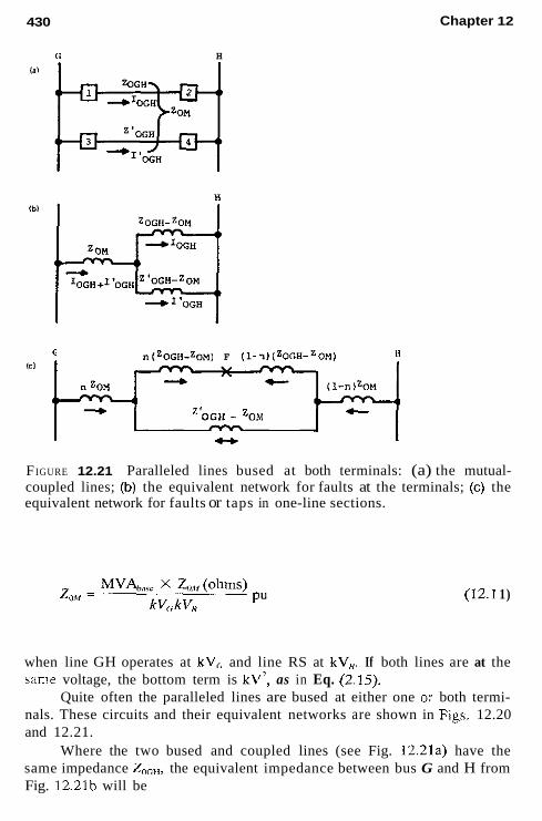
430
G H
Chapter 12
Y
n (zOGH-zOM) F (1-1) (ZOGH-ZOMl
"OGH - 'OM
c,
FIGURE 12.21 Paralleled lines bused at both terminals: (a) the mutual- coupled lines; (b) the equivalent network for faults at the terminals; (c) the equivalent network for faults or taps in one-line sections.
(12.1 1)
when line GH operates at kV,, and line RS at kV,,. If both lines are at the same voltage, the bottom term is kV', as in Eq. (2.15).
Quite often the paralleled lines are bused at either one OJ both termi- nals. These circuits and their equivalent networks are shown in F~gs. 12.20 and 12.21.
Where the two bused and coupled lines (see Fig. 12.21a) have the same impedance Z(,,,,, the equivalent impedance between bus G and H from Fig. 12.21b will be
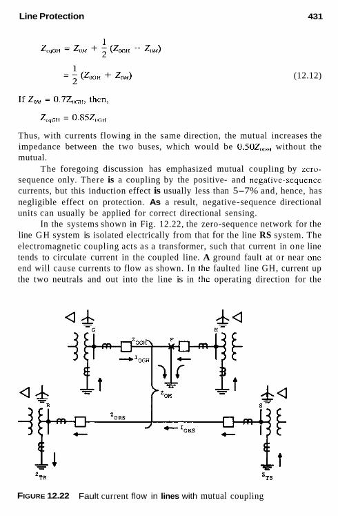
Line Protection 431
(12.12)
Thus, with currents flowing in the same direction, the mutual increases the impedance between the two buses, which would be 0.502,,,,, without the mutual.
The foregoing discussion has emphasized mutual coupling by zero- sequence only. There is a coupling by the positive- and negative-sequencc currents, but this induction effect is usually less than 5-7% and, hence, has negligible effect on protection. As a result, negative-sequence directional units can usually be applied for correct directional sensing.
In the systems shown in Fig. 12.22, the zero-sequence network for the line GH system is isolated electrically from that for the line RS system. The electromagnetic coupling acts as a transformer, such that current in one line tends to circulate current in the coupled line. A ground fault at or near onc end will cause currents to flow as shown. In the faulted line GH, current up the two neutrals and out into the line is in thc operating direction for the
FIGURE 12.22 Fault current flow in lines with mutual coupling

432 Chapter 12
directional ground relays at both G and H. They should operate to open up the breakers at G and H. Before that happens, current I,,,, is induced in line RS. The directional unit a! S will operate as the current is up the neutral and out into the line. The directional unit at R also operates, as current in and down the neutral is equivalent to u p and out the line. The magnitude can be large enough to operate the overcurrent units, with the result that either breaker at R or S, or both, may be tripped incorrectly. The magnitude of the current in line RS is
(12.13)
If the G and R buses or the H and S buses are i n close proximity, so that the grounded-neutral C T in the two banks can be paralleled, correct polarizing can be obtained. The faulted line current up the neutral will be greater than the induced current down the neutral.
The 3V,, voltage for Fig. 12.22 also will not provide correct polarizing. Correct directional sensing can be obtained by the use of negative sequence, but the induced 31, may be sufficient to operate the overcurrent units. For Fig. 12.22 this would possibly cause the S terminal ground relays to misopcrate.
Circuit switching in a zero-sequence electrically intcrconnected systcrn can result in zero-sequence isolation and induced circulating currents. An example is shown in Fig. 12.23. Lines GH and RH are mutually coupled and are connected together at bus H. For the ground fault c l o ~ e to breaker 2, the zero-sequence current flows are shown in Fig. 12.23a. This is defined by the equivalent circuit of Fig. 12.20. If the fault is in the zone of the instantaneous units at 2, they will operate fast to open breaker 2. This now isolates the two circuits electrically, as shown in Fig. 12.23b, and, until breaker 1 opens, an induced current circulating in the line RH system re- verses the l ine current and causes current to flow down instead of up in the transformer neutral at station R. Zero-sequence directional units, either cur- rent or voltage polarized, would operate at both ends to indicate an internal fault on line RH. Thus, incorrect tripping of either hrcaker 3 or 4, or both, can occur. This is a “race” with a possibility that breaker 1 will open to clear the fault before relays 3 or 4 can operate. This situation has explained intermittent incorrect tripping in several systems, which was solved by ap- plying negative-sequence directional sensing.
Multiple mutual coupling can cause current reversals in systems that are not zero-sequence electrically isolated. A n example is shown in Fig. 12.24. The two lines G to H are both coupled with the line R to S. Station

Line Protection 433
- Ibl
- -
- - FIGURE 12.23 Zero-sequence electrical circuit isolation by switching, causing mutual to reverse current: (a) initial fault near breaker 2; (b) breaker 2 trips by instantaneous relays.
H is a very large and solidly grounded station. Therefore, very high ground- fault currents flow from H to the fault near station G. With the system interconnected, as shown, the normal zero-sequence current flow to the fault should be up the neutral at station S and over the line from S to R to join the current at R and continue through line RG to the fault. However, the very large currents coupled to line RS can result in the reversal of line RS current from its normal anticipated direction. This reversal is shown in the figure. Again, zero-sequence current or voltage directional units would op- erate at both R and S, to sugzest a fault on line RS with possible incorrect tripping before the faulted line relays can operate and the breakers clear the fault.

434 Chapter 12
t FIGURE 12.24 circuit isolation.
Current reversal by mutual without zero-sequence electrical
FIGURE 12.25 sequence directional sensing.
Example of misoperation with mutual coupling and negative-

Line Protection 435
There is a very high probability of this condition occurring more fre- quently as environmental and economic concerns force the use of existing rights-of-way for more lines. As a result, mutual coupling is an increasing problem. Hence, it is very important that all mutuals be included in the fault program and carefully considered in protection.
As has been suggested, negative-sequence directional sensing can often provide correct indications, but it does not solve all problems. In Fig. 12.24, negative-sequence current would flow from S to R, so a negative-sequence directional unit at S senses a fault in line RS and with overcurrent sufficient to operate the zero-sequence fault detectors, relay S tends to operate. At R the negative-sequence directional unit blocks this relay operation.
A n incorrect operation with negative-sequence ground directional re- lays occurred to open breakers 3 and 5 for a ground fault out on line from breaker 1 (Fig. 12.25). The several lines were coupled as shown. The ground fault induced sufficient current to circulate in the secondary loop to operate the overcurrent zero-sequence units. Negative sequence from the industrial plant flows through both paralleled lines, so both directional units at the industrial plant substation closed. The result was incorrect tripping of both breakers 3 and 5 and, unfortunately, dumping of an important load. This particular problem was corrected by raising the overcurrent settings at break- ers 2, 3, 4, and 5 above the induced current, as the exposure to line 1 was short, so the higher setting still provided good protection for faults on lines 2-3 and 4-5.
12.25 GROUND DISTANCE RELAYING WITH MUTUAL INDUCTION
The mutual coupling will produce either a higher apparent impedance and relay underreach or a lower apparent impedance and relay overreach. Current flowing in the paralleled line in the same direction as the fault current in the protected line will cause a higher apparent impedance [see Eq. (12.9)] and underreach. Current flowing in the opposite direction produces a lower apparent impedance and overreach.
Consider ground distance relays at breaker 3 (see Fig. 12.21a) with zone 1 set for 85% of the line 3-4 impedance, without any mutual com- pensation. Zone 1 will reach approximately 70%, with current in line 1-2 flowing from 1 to 2 as shown. If breaker 4 opens first, the current in line 1-2 reverses to cause zone 1 at 3 to reach out and cover approximately 100% of the opened line.
Zone 2 should be set for approximately 150% of the line section to ensure that it will cover all of the line for primary protection with current

436 Chapter 12
in the parallel line flowing in the same direction. With this setting, zone 2 of breaker 3 should coordinate correctly with breaker 2, zone 2.
As a general rule, mutual compensation is not recommended for ground distance relays. If it is used, care must be taken to ensure proper operation when the paralleled line current changes direction from that for which the compensation was set.
12.26 LONG EHV SERIES-COMPENSATED LINE PROTECTION
Series capacitor banks are frequently inserted in long power lines to reduce their total impedance, thereby permitting the transmission of more power with less loss and for higher system stability limits. The capacitors may be inserted in the line at any point, but for economic reasons, they are often installed in the line at the terminal stations, as illustrated in Fig. 12.26. In this example, directional mho distance relays can operate undesirably, as
I Ibl
FIGURE 12.26 Protection problems encountered with series-compensated transmission lines: (a) a typical series-compensated line with series capacitor banks at the station terminals; (b) R-X and distance relay diagrams with capacitor banks in service; (c) R-X and distance relay diagrams with capac- itor banks out of service.
Line Protection 437
shown in Fig. 12.26b. The distance relays at 1 set to protect line GH cannot see faults in capacitor Go and part of the line, as this impedance area falls outside the circular operating characteristics. However, the distance relays at 3 for the protection of the line to the left of bus G do undesirably operate for faults in the capacitor and part of line GH. As a result, distance relays are not recommended for these lines unless one is willing to assume that the capacitor protective gaps will always short out the capacitor for faults in this problem area. This is a reasonable g a d l e , for the gaps are fast and reasonably reliable. Zone 1 solid-state relays may require a short-time delay; electromechanical relays probably will not.
When the gaps flash, the line becomes as shown in Fig. 12.26~. To cover the long line without the capacitors, a long reach or large ohm setting is required for zone 2 (and zone 3 if used). This setting may be a problem with load or recovery stability limits, so that one of the restricted distance characteristics of Fig. 6.12 will be required. Also, with the capacitors in service, zone 2 or zone 3 reach may cause coordination problems with relays at breaker 4 at station H.
Phase comparison pilot systems are preferred for these systems. Cur- rent-only systems will not have the problems of correctly sensing internal and external faults. Distance fault detectors do not have to be directional, so can be applied and set to operate for all faults in the line with or without the capacitor banks in service.
The segregated phase comparison system is especially applicable to these types of lines. This is outlined in Chapter 13.
12.27 BACKUP: REMOTE, LOCAL, AND BREAKER FA1 LUR E
Remote versus local backup was introduced in Section 6.4. In this section, backup is discussed in more detail. Backup protection has been included throughout the protection chapters in two basic forms: redundancy and re- mote. Redundancy is the additional protection provided in the primary pro- tection zone and sometimes extending into the adjacent system. Examples are three separate phase relays, instead of two or a single unit, to serve all three phases; phase relays backing up ground relays; timed-overcurrent and distance-timed zones backing up the instantaneous or pilot relays; and in EHV and UHV, two separate pilot systems. The degree of independence of the various protection schemes is a measure of the redundancy available. Very high redundancy is obtained for the EHV and UHV systems by oper- ating the two pilot systems from separate CTs and VTs or CCVTs, separate trip coils in the circuit breaker, and separate station batteries. If separate batteries are not available, separate fused supplies from the single battery

438 Chapter 12
are used. A similar arrangement is sometimes used for the voltage supply. This provides the maximum redundancy that is economically practical.
Remote backup is the overlapping of the primary relays in one pro- tection area into the adjacent areas. Thus, in Fig. 12.27a. relays 1 at station S , relays 5 at station T, and relays 8 at station R should provide backup to the relays and breaker 3 at station G for faults on line GH. That is, if breaker 3 does not open for these faults, the remote breakers 1, 5, and 8 must open to clear line GH faults.
As has been indicated, this becomes quite difficult or impossible, es- pecially for faults near station H because of the infeed effect from the cur- rents of the other lines. This tends to reduce the current or increase the impedance seen by the remote relays. If the remote relays can see line GH faults, the operating time may be relatively slow because of coordination requirements necessitated by the other lines out of service. Sometimes these difficulties can be solved by sequential remote tripping. If one remote ter- minal can operate on backup, its removal may result in a redistribution of fault current sufficient to operate the other remote backup relays.
G H
Fault .
ibi
H
Fault "
R
I
FIGURE 12.27 Power system configurations to illustrate backup protection: (a) backup on a single bus system; (b) backup on a ring or breaker-and-half bus system.
Line Protection 439
With the advent of EHV and UHV systems in the recent past, two problems developed. One was that, initially, the higher-voltage circuit break- ers were subject to a higher failure incidence than previously encountered. The other was that system stability required much faster backup. Thus, breaker failure-local backup systems were applied.
Instead of opening breakers 1, 5 , and 8 in Fig. 12.27a for a failure of either relays or breaker 3 to open on line GH faults, local backup would open the local breakers 2, 6, and 7. This can be’ done with minimum delay; typical times as low as 150-250 ms are in use.
Breaker failure is initiated when the primary protection operated, but the breaker does not open. Local backup is identical except that a second and independent primary relay system should be provided to cover the fail- ure of the relays to operate. As indicated, very high redundancy in relay systems is used for higher-voltage systems.
When local backup is applied to lower-voltage systems, careful atten- tion should be given to adequate relay redundancy to cover all possible relay failures. Remote backup by its separate location provides 100% redundancy for the faults within their operating range.
Remote backup is still important as an additional and “last resort” protection, and is necessary with ring or breaker-and-a-half buses. This is illustrated in Fig. 12.27b. For faults on line GH, breakers 1 and 2 at bus G are tripped. If breaker 1 fails to open, local backup would trip the necessary breakers o f f bus G (not shown). If breaker 2 fails to open, local backup would trip breaker 3, but the fault is still supplied through breaker 4 at station R. Thus, breaker 4 must be opened. This can be accomplished by remote backup operation of the relays at 4. With the infecd through breakers 1 and 3 removed, the possibility of relays 4 seeing faults on line GH is increased. Transfer trip of breaker 4 by the local backup at G is another possibility. This requires information that breaker 2 is in trouble and not breakers 1 or 3.
Typical local backup-breaker failure schemes are shown in Fig. 12.28. The trip circuits of the two redundant (independent) relay systems are in- dicated as 1 and 2, primary and secondary. Where the secondary system is a pilot type. its operating times can be equal to or faster than the primary system. With a single trip coil on the breaker, the primary directly trips the breaker by energizing the trip coil 52TC,, and the secondary energized relay 94 which, in turn, operates 52TC,. With double trip coils, 94 is omitted and the secondary system directly energizes the second trip coil 52TC2.
At the same time, auxiliary relays 62X and 62Y are energized. Either relay operates a timer supervised by a 50 relay. This is a low-pickup non- directional instantaneous overcurrent relay with a high dropout ratio. It is generally connected in two phases and ground. The phase units should be

440 Chapter 12
1 8 2 system Relay Trips (Primaryl
dc Neg
o-$ Time= =+* Multiple 8 6 contact*
dcNeg
* 8 S multi-contact relay trips a11 local breakers necessarv to clear fault and optionally to transfer triP the remote end termina1

Line Protection 441
Line Section source Load Minimum Contribution to Line Faults
Time Overcurrent for phase and/or ground faults with instantaneous avercurrent u n i t s where applicable.
Time overcurrent for phase and/or gronnd faults with instantaneous overcurrent units where applicable. (With no other downstream disconnect device, instantaneous phase and/or qround overcurrent units can be w e d . but time overcurrent recommended as back-up.)
FIGURE 12.29 General summary and suggested protection for radial lines and feeder circuits. Fuses or reclosers, may be used either downstream or upstream, in which case the time and instantaneous overcurrent relays must be selected and set to coordinate with these other devices. Complete coor- dination may not always be possible under all possible operating conditions. When minimum fault current is less than the maximum possible load current, apply a distance-controlled overcurrent relay.
able to carry the maximum load at their low settings. This 50 relay monitors the current through the breaker and provides a final check on breaker current flow, with fast opening to stop the timer should the breaker open late. The operation o f the timer energizes a multicontact auxiliary (86) relay, which i s the only one that i s manually resettable. The 86 relay contacts initiate tripping of all the breakers locally required to clear the fault, and may also initiate a transfer trip signal to the remote terminal(s) to ensure that the relays have operated correctly for the internal fault. There are several variations of the schemes and connections for the various bus configurations.
FIGURE 12.28 Typical breaker failure-local backup dc (schematic): (a) typ- ical circuit breaker trip systems and auxiliaries for breaker failure-local backup (where breakers have double trip coils, 94 relay coil, and contact is omitted and the second trip coil 52 TC, connected in place of the 94 relay coil); (b) typical contact logic for breaker failure-local backup; (c) typical solid-state logic for breaker failure-local backup.

442 Chapter 12
FIGURE 12.30 General summary and suggested protection for loop lines and circuits. Protection at both terminals: 1. Up to 34.5-69 kV: directional time-overcurrent for phase or ground with
nondirectional or directional instantaneous overcurrent where applicable. 2. 34.5-115 kV: directional distance (two or three zones) for phase, same
as item 1 for ground, alternate-ground distance. 3. 69-230 kV: pilot relaying (see Chap. 13) for phase and ground as primary
protection, backup as item 2. 4. 230 kV and above: two pilot systems (primary and secondary) (see Chap.
13) for phase and ground, additional backup as item 2. 5. For very short lines at any voltage level: pilot wire or pilot type (see Chap.
13) for phase and ground. backup per 1 or 2, but coordination with other protection may not be completely possible.
6. Multiterminal and tapped lines: pilot-type relays generally required unless load type impedance or transformer connections will permit proper discrim- ination for external faults.
12.28 SUMMARY: TYPICAL PROTECTION FOR LINES
Typical protection recommended and generally applied for the protection of lines i s outlined in Fig. 12.29 for radial lines and feeders, and in Fig. 12.30 for loop lines. Once again there are many variables, circumstances, operating conditions, and local practices that can modify these general suggestions and practices. The pilot systems indicated are discussed in Chapter 13.
BIBLIOGRAPHY
See the Bibliography at the end of Chapter 1 for additional information
ANSUIEEE STANDARD C37.95, Guide for Protective Relaying of Consumer-
ANSI/IEEE Standard C37.103, Guide for Differential and Polarizing Relay Circuit
ANSIIIEEE Standard C37.108, Guide for the Protection of Network Transformers,
Utility Interconnections, IEEE Setvice Center.
Testing, IEEE Service Center.
IEEE Service Center.

Line Protection 443
Blackburn, J. L., Voltage induction in paralleled transmission circuits, MEE Trans., 81, 1962, pp. 921-929.
Bozoki, B., J. C. Benney, and W. V. Usas, Protective relaying for tapped high voltage transmission lines, IEEE Trans. Power Appar Syst., PAS 104, 1985, pp. 865- 872.
Burke, I. J. and D. 1. Lawrence, Characteristics of fault currents on distribution systems, IEEE Trans. Power Appar. Sysr., PAS 103, 1984, pp. 1-6.
Curd, E. and L. E. Curtis, Procedure for an Overcurrent Protective Device Time- Current Coordination Srudy, Val. 1, No. 1 Section 110, Square D Power Systems Engineering Data, Square D. Co., Middletown, OH, 1979.
Distribution System Protecrion Manual, Bulletin No. 71022, McGraw-Edison Co., Canonsburg, PA.
Dugan, R. C. and D. T. Rizy, Electric distribution protection problems associated the interconnection of mall dispersed generation systems, IEEE Trans. Power. Appar: Syst., PAS 103, 1984, pp. 1121-1127.
de Mello, F. P., J. W. Feltes, L. N. Hannett, and J. C. White, Application of induction generators in power systems, IEEE Trans. Power Appor Syst., PAS 101, 1982,
Elmore, W. A. and J. L. Blackburn, Negalive sequence directional ground relaying, AIEE Trans., 81, 1962, pp. 913-921.
Griffin, C. H., Principles of ground relaying for high voltage and extra high voltage transmission lines, IEEE Trans. Power Appar Syst., PAS 102, 1983, pp. 420- 432.
IEEE-PES, Protection Aspects of Multi-terminal Lines, IEEE-PES Special Publica- tion 79TH0056-2-PWR, IEEE Service Center.
IEEE Tutorial Course, Application and Coordination of Reclosers, Sectionalizers and Fuses, 80 EH0157-8-PWR, IEEE Service Center.
Lewis, W. A. and L. S. Tippett, Fundamental basis for distance relaying on a three- phase system, AIEE Trans., 66, 1947, pp. 694-708.
Power System Relaying Committee, Local backup relaying protection, IEEE Truns. Power Appur. Syst., PAS 89, 1970, pp. 1061-1068.
Power System Relaying Committee, EHV protection problems, IEEE Trans. Power Appar Syst., PAS 100, 1981, pp. 2399-2406.
Power System Relaying Committee, Distribution line protection practices, industry survey analysis, IEEE Trans. PowerAppar. Syst., PAS 102,1983, pp. 3279-3287.
Rook, M. J., L.E. Gaff, G. J. Potochnry, and L. J. Powell, Application of Protective relays on a large industrial-utility tie with industrial co-generation, IEEE Trans. PowerAppar: Sysf.., PAS 100, 1981, pp. 2804-2812.
Wang, G. N., W. M. Moffatt, L. J. Vegh, and F. J. Veicht, High-resistance grounding and selective ground fault protection for a major industrial facility, IEEE Trans. lnd. AppL, IA20, July-Aug. 1984, pp. 978-985.
pp. 3385-3393.

13 Pilot Protection
13.1 INTRODUCTION
Pilot protection used for lines provides the possibilities of high-speed si- multaneous detection of phase- and ground-fault protection for 100% of the protected section from all terminals: the ideal primary protection goal. It is a type of differential protection for which the quantities at the terminals are compared by a communication channel, rather than by a direct-wire inter- connection of the relay input devices. The latter is impractical because of the distances between the several terminals. Similar to differential schemes, pilot schemes provide primary zone protection and no backup. Thus, they do not require coordination with the protection in the adjacent system unless additional backup is included as a part of the pilot scheme.
This protection is applicable at all voltages. In actual practice, it is usually applied to short lines at all voltages and to most lines at about 69- 115 kV and higher. The application key is the importance of the circuit in the power system and the necessity for rapid clearing of faults for stability and service continuity.
This chapter outlines the fundamentals and basic operation of the sev- eral systems in common use in the United States. Today, many pilot systems are solid-state, desirable in these schemes because several relay functions must be coordinated for which logic circuitry is preferable and faster than
444

Pilot Protection 445
relay contact logic. As a result, many variations are possible and exist, each with promoted sophistications and features beyond the scope of this book.
13.2 PILOT SYSTEM CLASSIFICATIONS The pilot protection systems can be classified into two categories:
1. By channel use: a. Channel not required for trip operations; known as blocking
systems b. Channel required for trip operations; known as transfer frip
systems. By fault defectorprinciple: the comparison at the several terminals of: a. b.
c.
2.
Power flow, known as directional comparison The relative phase position of the currents, known as phase comparison Wave deflection from a fault: a relative new ultrahigh-speed system with application primarily to EHV transmission lines
A particular scheme is usually described or identified by a combination of these two categories. The major schemes in use can be identified more specifically:
A. Directional comparison systems 1. Directional comparison blocking 2. Directional comparison unblocking 3. Overreaching transfer trip 4. Underreaching transfer trip
a. Nonpermissive b. Permissive
B. Phase comparison systems 1. “Pilot wire” 2. Single-phase comparison: blocking 3. Dual-phase comparison: unblock 4. Dual-phase comparison: transfer trip 5. Segregated phase comparison
C. Directional wave comparison

446 Chapter 13
13.3 PROTECTION CHANNEL CLASSIFICATIONS
The channels used for protective relaying are as follows:
1. Piloi wires: A twisted wire pair for transmitting 60-Hz, 50-Hz, dc between terminals. Originally telephone pairs were used, privately owned dedicated pairs are preferred. Audio frequency iones: On-off or frequency shift types over wire pairs, power line carrier, or microwave. Power line carrier: Radio frequencies between 30 and 300 kHz, transmitted principally over high-voltage transmission lines. On- off or frequency shift types are used. Microwave: Radio signal between 2 and 12 GHz, transmitted by line-of-sight between terminals. Multiple channels with protection by a subcarrier or audiotone. Fiber opfics: Signals transmitted by light modulation through an electrical nonconducting cable. Cables are included as part of ground wires, wrapped around the power cable, strung parallel with a power line, or buried along the right of way. The cable eliminates electrical induction, noise, and electrical insulation problems.
2.
3.
4.
5.
These are discussed in more detail in Section 13.14
13.4 DIRECTIONAL COMPARISON BLOCKING PILOT SYSTEMS
This is the oldest type of system, being first used in the 1930s. It is still in very wide use and is the most versatile and flexible system, especially ap- plicable for multiterminal lines. The direction of the power flow at the ter- minals is compared. For internal faults, the power (current) flows into the line at the terminals, so simultaneous high-speed tripping at the terminals is permitted. For external faults, the information that current flows out at one of the terminals is used to block tripping of all terminals.
This system is usually applied with an “on-off” power-line carrier channel (see Sec. 13.14.1 and Fig. 13.7). The transmitter-receivers at the two terminals are tuned to a common RF frequency. Separate frequencies can be used, as well as other types of channels. A basic schematic of this system is shown in Fig. 13.1. In general, distance relays for phase faults and directional instantaneous overcurrent relays for ground faults are used as fault detectors (FD). The channel signal is initiated by distance phase and instantaneous overcurrent units known as carrier start (S) relays. The fault

Pilot Protection
FDl
+I ---- SI.
447
I_ Protection zone - I I
(a) power system and reley setting dirigram;
s1
FD1
I I I
Station H Logic station G Logic
(b) Solid State Logie Diagrams
Blocking Signal +@ RR Receiver
a t o p Blocking InitiaFe signa1 Blocking
Signal
(c) Contact Logie Diagram
FIGURE 13.1 ing pilot systern.
Basic operating principies of the directional cornparison block-

448 Chapter 13
detectors (FD) must be directional and set to overreach all remote terminals under all operating conditions. Because this is also the requirement for zone 2 distance relays, these are used in the pilot system. The pilot trip for internal faults is in parallel with the time-delay T2 trip.
The carrier (channel) start units must he set more sensitively or to reach farther out on the line than the remote fault detector. In other words, in Fig. 13.la, S, units at breaker 1 bus G must operate for all phase or ground faults to the left of 1 that can operate FD, at breaker 2, bus H. Similarly, S2 must operate for all phase and ground faults at bus H and to the right that can operate FD, at G. Normally, a zone 3 distance relay is used, hut connected to see out of the protected line section instead of into the line, as discussed in Chapter 12. The conventional mho characteristic that passes through the origin cannot respond adequately to provide blocking for the possibility of a solid zero-volt fault just external to the relay. Ac- cordingly, the zone 3 distance relay has a small current-only torque or bias to provide positive operation for these faults.
Both electromechanical and solid-state systems are in service, and their basic operation is the same. A typical operating logic diagram is shown in Fig. 13.lb. For the logic boxes, “1” is used to indicate a logic input or output signal, and “0” for no or an insufficient input or output signal. The “AND” logic box requires all inputs to be 1 in order to have a 1 output. The small circle (0) at the box indicates that a 1 appears to the box as a 0 and vice versa. The top numbers in the timer logic box represent the time in milliseconds for an output to occur after an input (pickup time). The lower number is the reset (dropout) time.
The operation for an external fault, for example, on bus H or on the line(s) to the right of the bus, is as follows:
Relays 2 ar bus H FD, does not operate, S2 does operate. AND H, thereby has both inputs 1 to key the carrier transmitter on. The RF signal f, is received locally and transmitted to station G. AND H, has two 0 inputs; neither will provide an output. Thus, breaker 2 is not tripped.
Relays I at bus G: The RF signal f, received provides a 0 on AND G, so there is no output to trip breaker 1 even though FD, operates. FD, operation provides a 0 on AND G,, so the transmitter is not keyed, even though S, may operate on this external fault.
Thus, the carrier (channel) signal at H i s used to block the overreaching trip relays at G from operating on this external fault. Correspondingly, an external fault on or to the left of bus G will provide a blocking signal from G to H to block the overreaching H relays from tripping.
For internal faults in the protected zone:
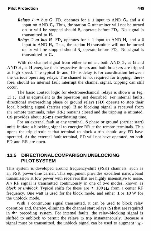
Pilot Protection 449
Relays 1 at bus G: FD, operates for a 1 input to AND G2 and a 0 input on AND G,. Thus, the station G transmitter will not be turned on or will be stopped should S, operate before FD,. No signal is transmitted to H.
Relays 2 at bus H FD2 operates for a 1 input to AND HZ and a 0 input to AND H,. Thus, the station H transmitter will not be turned on or will be stopped should Sz operate before FD,. No signal is transmitted to G.
With no channel signal from either terminal, both AND G2 at G and AND H, at H energize their respective timers and both breakers are tripped at high speed. The typical 6- and 16-ms delay is for coordination between the various operating relays. The channel is not required for tripping; there- fore, should an internal fault interrupt the channel signal, tripping can still
The basic contact logic for electromechanical relays is shown in Fig. 1 3 . 1 ~ and is equivalent to the operation just described. For internal faults, directional overreaching phase or ground relays (FD) operate to stop their local blocking signal (carrier stop). If no blocking signal is received from the remote terminals, relay (RR) remains closed and the tripping is initiated. CS provides about 16-111s coordinating time.
For an external fault at any terminal, S phase or ground (carrier start) units initiate a blocking signal to energize RR at the remote terminals. This opens the trip circuit at that terminal to block a trip should any FD have operated. At the external fault terminal, FD will not have operated, so both FD and RR are open.
occur.
13.5 DIRECTIONAL COMPARISON UNBLOCKING PILOT SYSTEM
This system is developed around frequency-shift (FSK) channels, such as an FSK power-line carrier. This equipment provides excellent narrowband transmission at low power with receivers that are highly insensitive to noise. A n RF signal is transmitted continuously in one of two modes, known as block or unblock. Typical shifts for these are ? 100 Hz from a center R F frequency. One watt is used for the block mode, and either 1 or 10 W for the unblock mode.
With a continuous signal transmitted, it can be used to block relay operation and, thereby, eliminate the channel start relays (S) that are required in the preceding system. For internal faults, the relay-blocking signal is shifted to unblock to permit the relays to trip instantaneously. Because a signal must be transmitted, the unblock signal can be used to augment trip-

450 Chapter 13
ping. Also, this type of channel can be monitored continuously, which is not possible with on-off channels.
A typical unblock system is shown in Fig. 13.2. As illustrated in Fig. 13.2a, only fault detectors are required. They are of the same types and setting as described in Section 13.4. Both the phase and ground relays must always overreach all remote terminals for all operating conditions to provide 100% internal line-fault protection.
As documented by the logic diagrams of Fig. 13.2b and c, the oper- ation is as described in the following. This is a typical system; other ar- rangements are possible.
13.5.1 Normal-Operating Condition (No Faults)
Both frequency shift transmitters at station G (FSK T,) and station H (FSK TH) are transmitting in the block mode, so that from their respective receivers (FSK R,) and (FSK RH), the block signal is 1 and the unblock signal 0. Thus, the outputs of OR G, and OR G, at station G and of OR H, and OR H2 at station H are all 0. FD, at G and FD, at H are not operated, so the AND G, and AND H3 inputs are all 0 and no trip is indicated.
As shown, separate frequency channels are required between the sta- tions indicated by f, and f2. Typical spacings between these are about 1 kHz for narrowband equipment. Transmission of these frequencies is continuous during their operation.
13.5.2 Channel Failure
If one channel is lost for any reason, so that there is no block signal output, the protection is blocked out of service and an alarm is sounded. In Fig. 13.2b, if the block signal from FSK R, is lost (goes to 0) without a shift to unblock mode, so that it remains at 0 at station G, OR G, has a 1 input and output. Now AND G, has both inputs 1 to energize the timer. After 150 ms the relay system is locked out with an alarm.
13.5.3 External Fault on Bus G or in the System to the Left
Relays I at station G: FD, relays do not operate. This directly prevents tripping of breaker 1 and permits the FSK T, transmitter to continue in the blocking mode.
Relays 2 at station H Block signal 1 continues, so OR H, has no input; hence, no output. Thus, the lower input to AND H, is 0, so it can have no output even though FD, has operated with a 1 on AND H,. Thus, tripping is blocked by the blocking signal from

Pilot Protection 451
H FD1 H A
I I m- Protection Zone __*
I n > power system and relay selling dingmm:
Lockout , Signal
1
Lockout sign.,
(b) Solid State Logic Diagrams
Unblock Signal from Remote Terminal
FD Local.
( e ) Simplified Logic Diagram
FIGURE 13.2 Basic operating principles of the directional comparison un- blocking pilot system using a frequency shin channel.
452 Chapter 13
station G. The operation of FD, keys the transmitter FSK TH to n n b 1 o c k .
Buck ut station G: Reception of the unblock signal from station H by FSK & operates OR Gi, but AND G, cannot operate because FD, has not operated.
13.5.4 Internal Faults in the Protected Zone
At sfufion G: FD, operates to key FSK Tc to unblock and to input 1 to AND G,.
At stution H: FD, operates to key FSK Tw to unblock and to input 1 to AND H3.
At bofh stations: The operation is the same. Considering station G, the unblock signal 1 with the FD, signal 1 operates AND G, to initiate breaker 1 tripping after about a 4- to 8-ms delay for operating co- ordination. This unblock signal is not necessary for tripping. Ke- moval of the block signal operates OR G, and, in turn, AND G , if the unblock signal is delayed or not received because of the fault. The bypass from OR G, to AND G, causes it to operate with 0 unblock signal on AND G, . This AND G, output lasts until the timer operates, which is sufficient to permit a trip signal through OK GZ and AND G3.
Therefore, this system operates as a “blocking type,” where no chan- nel signal is required for the timer interval (150 ms as shown), then becomes a “transfer trip” type. This provides a combination of the advantages of both types, as reviewed in a later section. It is applicable to power-line carrier channels, which should not be used for the transfer trip systems.
13.6 DIRECTIONAL COMPARISON OVERREACHING TRANSFER TRIP PILOT SYSTEMS
Power-line carrier channels are not used or recommended for these systems. A signal must be received from the remote terminal(s) to trip, and with power-line carrier, the signal could be intempted or shorted out by a fault. Therefore, these systems are used normally with audiotones over telephone circuits or modulated on microwave channels. “Trip-guard” tones are used. The guard is monitored. The arrangement is similar to that described in the foregoing. Loss of channel (guard) for about 150 ms locks out the protective relays from tripping and alarms. After the guard signal returns, the relays are restored to operation after about 150 ms.
A typical system i s shown in Fig. 13.3. The same types and settings of directional phase distance and ground directional instantaneous overcur-
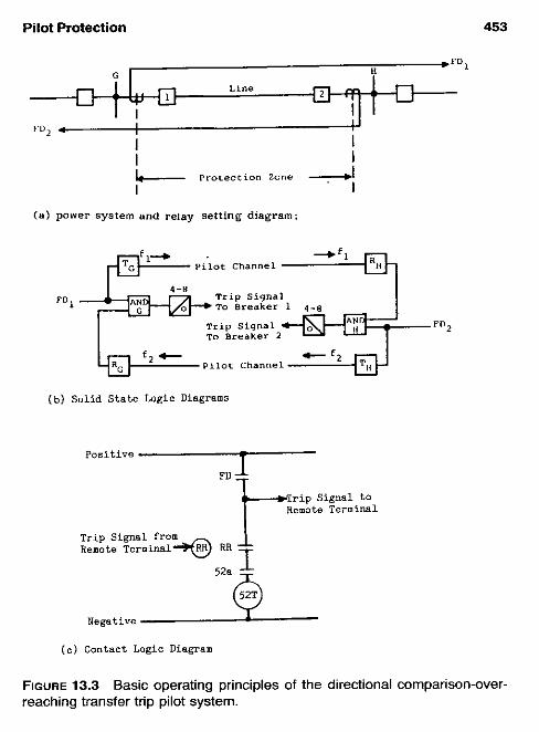
Pilot Protection 453
H
fm2 . I I I I I_ PrOLeCLlOn zane 2 I I
(a) power systern and reiay setting diagram:
-Fl PLlot Channel
b% Piiot Channel Cf’d ( b ) Solid State Logic Diagrams
Positive -
r i p Signal to Remote Terminal
Trip Signal from Remote Terminal+ RR T
Negative
( c ) Contact Logic Diagram
FIGURE 13.3 reaching transfer trip pilot system.
Basic operating principies of the directional comparison-over-

454 Chapter 13
rent relays are used, as for the previous systems. Again, it is important that these be set to overreach the remote terminal(s) under all operating condi- tions. If we consider Fig. 13.3h,
13.6.1 External Fault on Bus G or in the System to the Left
Relays I at station G: FD, relays do not operate. Tripping cannot take place. Transmitter T, continuous to operate in the guard mode.
Relays 2 at station H : FD, relays operate, hut cannot trip, for receiver RH does not input to AND H in the guard mode. FDI does shift transmitter T,, to the trip mode, so at station G this receiver energizes the AND G, but as before, FD, does not.
Thus, both terminals are blocked from tripping on the external faults.
13.6.2 Internal Faults in the Protected Zone
The operation is the same at both terminals. FD, and FD, both operate to shift their respective transmitters to the trip mode. This is received at the remote receivers and provides an input into the AND G and AND H which, with the FD, and FD, inputs, provide a trip output, and both breakers are operated simultaneously at high speed. The 4- and 8-ms delay provides coordination time between the various component?
The operation with electromechanical relays is the same as for solid state and is shown in Fig. 13 .3~ . Directional phase or ground relays (FD) operate for faults on the line or beyond and send a trip signal to the remote terminal to close RR. If the fault is internal the FD at both terminals operate, send trip signals, and thus, both ends trip. If the fault is external, the FD that does not operate, does not permit tripping and does not send a trip signal; therefore, the other terminal cannot trip.
13.7 DIRECTIONAL COMPARISON UNDERREACHING TRANSFER TRIP PILOT SYSTEMS
These systems require that the fault detectors be set such that they always overlap, but do not overreach any remote terminal under all operating con- ditions. Phase directional distance zone 1 units meet this requirement and so are used in this system. Instantaneous overcurrent relay “reaches” vary with current magnitude, and it becomes difficult, and sometimes impossible, to ensure that these relays for ground faults always overlap, but not over-

Pilot Protection 455
reach. Thus, distance ground relays are recommended for this system and set as in the foregoing for zone 1.
The channels required are the same as those for the overreaching trans- fer trip systems. Two types exist: (1) nonpermissive, shown in Fig. 13.4b, and (2) permissive (see Fig. 13.4~). With the setting indicated, all external faults do not operate any of the fault detectors. On the internal faults FD, at bus G and FD, at bus H both trip directly for faults in the area of the overlap. Both of these detectors key their respective channel transmitters to the trip mode. This provides a trip output at the receivers to directly trip the terminal breakers. No time delay is required.
This system is not in general use because of the very high security requirements of the channels. Any transient or spurious operation of the receiver will result in incorrect operation. Consequently, overreaching fault detectors, of the type and setting described in the foregoing are added. These are used to supervise the channel. As seen in Fig. 13.4c, a trip signal through the channel requires that the overreaching fault detectors operate so that AND G or AND H, or both, can have an output to trip the breakers.
The operation with electromechanical relays is illustrated in Fig. 13.4d. Because the directional phase or ground relays (FD) do not overreach any remote terminal, they can trip directly at each terminal. The operation of FD also sends a tripping signal to the remote terminals to close RR and directly energized the trip in the nonpermissive system. With the addition of optional overreaching phase and ground relays, as shown, the tripping by the remote terminal, is supervised. This is the permissive directional com- parison underreaching system.
13.8 PHASE COMPARISON: PILOT WIRE RELAYING-WIRE LINE CHANNELS
This widely used system for short lines was developed between 1936 and 1938. Dr. E. L. Harder conceived that a single-phase voltage
V, = k J , + kd, (13.1)
was representative of all types of power system faults and could be used for protection and could be compared over telephone circuits. The author’s first assignment in relaying was to do many fault calculations on typical systems to assure that this single-phase voltage V, was viable. Several other com- binations have been used to provide a single-phase voltage from the three- phase currents.
The three-phase and neutral currents are connected to a sequence filter, which provides a single-phase voltage output V,. One design is as Eq. (13.1)

456 Chapter 13
c r - - - - - - _ _ _ _ - - _ _ _ - _ _ _ _ - - - - PDPl
Line
F Q p 2 *---- _ _ _ _ _ _ _ _ _ _ _ _ _ _ _ _ _ _ _ _
--i Piotectlon zone
(a1 POWT Sustem and Relay Setting Diagram
Trip siqna1
F D 2 TO Breaker 2
f2 Pilot Channel
(b l Solid State Logic Diagrams - Nan-permissive Underreaching Transfer Trip
(e) Solid State Logic Diagrams - Permissive Underreaching Transfer T r i ?
Positive - - (Optional Ouerreachingl
;;;ot;;:rmi;;y Remote Trip Signal Terminal to J-4
52@
Negative
( d ) Contact Logic Diagram - Non-permissive. Perrnissive vith Optioml FD
FIGURE 13.4 reaching transfer trip pilot system.
Basic operating principles of the directional cornparison-under-

Pilot Protection 457
or, subsequently, as Eq. (13.2). Power system voltages are neither involved nor required.
V,: = k J , + kJ2 + k,I, (13.2)
I,, 12, lo are the positive-, negative-, and zero-sequence current com- ponents derived from the line currents I., Ihr I, and k, , k2, & are network factors adjustable by taps and the design of the sequence network. All types and levels of faults produce combinations of positive, negative, and zero sequence. Thus, all faults above the relay sensitivity can he detected. For ground faults & can he made large for high ground-fault sensitivity. With the filter output of Eq. (13.1) and where Z , = 5, the pbaserto-phase fault pickup is higher by ~ than the three-phase fault pickup (the phase-to- phase actual fault current is 0.866 less than three-phase current). For short lines this lower sensitivity to the phase-to-phase faults was seldom a prob- lem. With the network output of Eq. (13.2), the phase-to-phase fault pickup is lower (higher fault sensitivity) than the three-phase pickup.
The output voltage from the sequence networks V,: or the voltage from other-type networks is compared with the similar output voltage from the remote terminals. The system using a “telephone”-type wire line channel has been widely used over many years. The basic circuit is shown in Fig. 13.5. The sequence network voltage is passed through a saturating trans- former. This limits the voltage to essentially a constant magnitude of about 15 V; hence, it is independent of the wide variations that occur in fault currents.
This voltage is connected to the pilot wires through a restraint coil R, with an operating coil OP across the pair and the insulating transformer. Typically, a 4:l or 6 : l ratio transformer is used, providing a maximum pilot wire voltage of about 6 or 90 V. The pilot wire side insulation of this transformer is about 10-15 kV to ground and between the windings.
Current in the operating R coil tends to prevent relay trip operation, whereas current in the operating OP coil produces relay operation. With equal current in R and OP and above the pickup value, this relay operates to energize the breaker trip coil.
The operation of the system for external faults is illustrated in Fig. 13.5b. Through current, either load or to external faults, results in a circu- lating current through the pilot wire pair, as shown, with only a small portion passing through the operating OP coil. The higher current through the re- straint R coil prevents relay operation at both terminals.
For internal faults (Fig. 13.5c), current flowing to the fault essentially circulates through the restrain R and operating OP coils in series with a small current over the pilot pair. If the contribution to the fault from stations G and H were equal, no pilot wire current would flow. The other extreme

458 Chapter 13
Pilot Wire Station H çtation G Chame1
Q j [{l)j rr"l se 0 u e n c e i t t 7 NetWOrk
1nsu1atinq çaturatinq Transformer Transformer
Seq"e"Ce Network
Saturating Insulatinq Tranaformer Transformer
(a) Basic Schematic Using e Pi lat Wire Chame1
H External
Protected Line çection
+ F L m L T + Pilot Wires
t c t
(b) Sirnplified Circuit Illustrating Opcration for External Faults
G Interna1 H --* Fault c ..
n
(c) Sirnpliíied Circuit Illustrating Operation for Internal Faults
FIGURE 13.5 Typical pilot wire-relaying system for line protection. Principle also utilized with audiotones or fiber optics (see Sec. 13.8).

Pilot Protection 459
possibility is, say, no contribution to the fault from bus H; then, the current through G would divide between the local operating coil and, through the pilot wires, the remote operating coil at H. If the fault current through G in this instance is high enough, both terminal relays can operate to provide simultaneous high-speed tripping of both ends. This is occasionally quite desirable.
Thus, over a wide range of current magnitude and distribution, this system provides high-speed simultaneous protection for both phase and ground faults. As can be seen, this is a differential-type protection, operating on the total-fault current, and a 50- to 60-Hz phase comparison type.
Three terminal applications are possible with this system. The added terminal relay is connected across the pilot pair with its pilot pair forming a wye-connection with the other two pilot wire branches. The pilot wire- wye connection should have legs of equal impedance. Because different distances will exist between the terminals, balancing resistors are used to provide this balance.
Supervision of the pilot pair for opens, shorts, or grounds is obtained by circulating about 1 mil of dc current over the pair, with sensing relays at each terminal. These are connected at the midpoint of the insulating trans- former on the pilot-wire side. This winding is split at the midpoint and a small capacitor connected between the two halfs to permit the 50- to 60-Hz signals to pass. The supervisory dc voltage is applied across this capacitor. At the other end(s) sensing relays are connected across similar capacitors at those terminals. Interruption or increase of the circulating current provides alarm indications. This equipment can also be used for a transfer trip channel in either or both directions. For this, the dc current in the supervisory equip- ment is reversed and increased to operate the transfer trip relays.
With this supervision equipment connected to the pilot wires, special attention must be given to possible high voltage from induction or station ground rise. For personnel safety, neutralizing and mutual drain-gauge re- actors and gaps should be used in most applications.
13.9 PHASE COMPARISON: AUDIOTONE OR FIBER-OPTIC CHANNELS
The current-only system with a single-phase voltage to represent all types of phase and ground faults (see Sec. 13.8) was extended, about mid-l940s, for the protection of longer transmission lines. One typical system uses V,: of Eq. (13.2). This voltage is passed through a squaring amplifier that pro- duces square waves for transmission and comparison at the remote terminal.
For security, two-level fault detectors may be used, both overreaching, such that they operate for all internal phase and ground faults. Normally,

460 Chapter 13
these are current-operated units. Where the minimum internal fault currents are on the order of or less than maximum load current, distance units are applied for the phase-fault detectors. This means that the system now re- quires VTs and is not a current-only system. In either event, the high-level detector is set at about 125-250% of the low-level unit.
A typical system and its operation are illustrated in Fig. 13.6. At breaker 1, station G, the fault detectors are FD,, and ED,,, and at breaker 2, station H, FD2s and FD,,. The S units are set more sensitively (lower- current pickup or longer-distance reach) than the T units. As shown in the figure, the squaring amplifier produces square waves that are maximum on one half of the 50- to 60-Hz wave and zero on the other half of the wave.
With similar equipment and settings at the two terminals, the operation at bus G for relays 1 is as follows:
13.9.1 External Fault on Bus H or in the System to the Right
FD,, and FD, operate to input 1 to AND G, and AND G,, respectively. At station H, FD,, and FD,, (both nondirectional) operate to input 1 on AND H, and AND H,. Thus, FD2, and the squaring amplifier output start trans- mission of square waves from transmitter T,, over pilot channel f2 to receiver RG. The polarities are such that this train is as shown, and is negated as input to AND G,. Thus, AND G, is energized only for a very short interval, if at all, for short spikes of output considerably less than the 4 ms required for operation. For the external faults assumed, the currents into the line at 1 should be in phase with the currents out of the line at 2 for all practical purposes (line losses and phase shifts are normally negligible except for very long lines). Time delay is provided for the local signal to compensate for the differences and the channel delays; accordingly, tripping does not occur for the external faults. The system at breaker 2, station H operates in a similar manner, and both terminals operate similarly for faults on bus G and in the system to the left.
13.9.2 Internal Faults in the Protected Zone
All fault detectors at both terminals operate. At station H the current of relay 2 has reversed for the internal faults, so the received signal and the input to AND G, is essentially in-phase with the local square waves from relays at 1. These provide positive square output from AND G, and after 4 ms a trip output.
The full half-wave output shown assumes that the currents at stations G and H are 180' out of phase or flowing into the line in phase. With load flowing across the line, this is not true, but these systems can trip with the
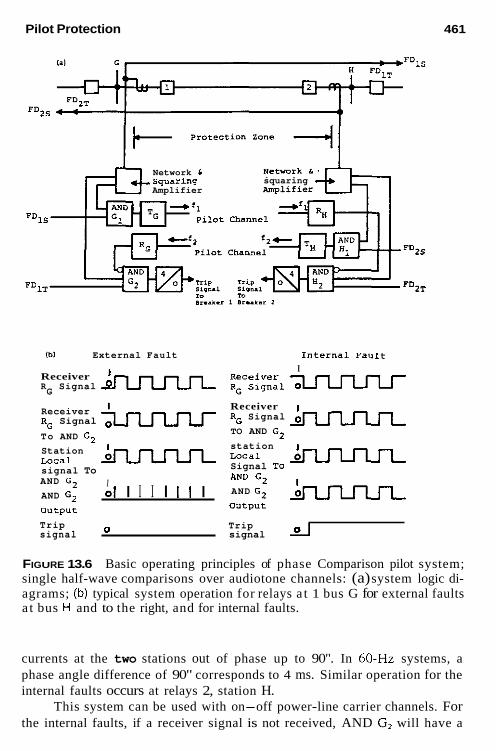
Pilot Protection 461
Network L squaring Amplifier
squaring Amplifier
I"
nr..*.z
Ibl External Fault Internal FaUlt I
Receiver ' R Signal G
Receiver RG Signal To AND G2 Station Local signal To AND G2
AND G2 DUtput
I 01 I I I I I 1 I
Receiver RG Signal TO AND G2
station Local Signal To AND G2
AND GI DUtpvt
Trip Trip signal O signal LI
FIGURE 13.6 Basic operating principles of phase Comparison pilot system; single half-wave comparisons over audiotone channels: (a) system logic di- agrams; (b) typical system operation for relays a t 1 bus G for external faults a t bus H and to the right, and for internal faults.
currents at the two stations out of phase up to 90". In 60-Hz systems, a phase angle difference of 90" corresponds to 4 ms. Similar operation for the internal faults occurs at relays 2, station H.
This system can be used with on-off power-line carrier channels. For the internal faults, if a receiver signal is not received, AND G, will have a

462 Chapter 13
1 input continuously. Trip operation can occur at both ends by the local signal input plus the local FD, operation.
The systems just described provide comparison on only one-half cycle. If the fault should occur on the zero-output half cycle, tripping for internal faults is delayed until the next half cycle.
If frequency-shift (FSK) power-line carrier or “mark-space’’ audiotone channels are available, comparison can be made on either half cycle of the 50- to 60-Hz wave. This is known as dualphase comparison. Equipment is required similar to that of Fig. 13.4 for comparing each half cycle. The square waves of one half cycle are transmitted by 1 on one frequency and 0 by the shift frequency. The other half cycle is transmitted similarly by a separate channel. Similar to Fig. 13.4, the unblock logic permits operation on internal faults if the channel signal is not received. The transfer trip mode is used in general for the audiotone-type channels.
Another technique for the comparison of the single-phase voltage from the sequence networks at the terminals is by pulse-period modulation. Here, the carrier period is varied linearly with the modulating signal amplitudes. A modulator develops the pulse train and the demodulator translates the pulse train into a magnitude wave. A delay equalizer ensures time coincident of the local and remote signals. The channel can be either audiotones or optic fiber.
13.10 SEGREGATED PHASE COMPARISON PILOT SYSTEMS
As indicated in Chapter 12, phase comparison pilot systems are preferred for the protection of series-compensated transmission lines. Dual-phase com- parison systems are in service with favorable operating records. However, these types of lines can have very severe harmonics, so i t is possible that networks to provide the current-derived operating voltages may provide in- correct information on the potential highly distorted current waves from faults on the system. These networks basically are “tuned” to the 50- to 60-Hz current waveform.
Accordingly, a system of individually comparing the phases, rather than a single voltage for the three phases, is used. The voltage derived from the single-current magnitude is independent of power-system frequency and waveform. However, multiple channels are required in these systems. The two common systems are (1) comparing I , - Ib at the terminal ends over one channel, and 31, at the terminals over another channel; or (2) comparing each phase current I,,, Ib, and I, at the terminals through three channels. The current square waves are compared basically as described for other types of phase comparison systems.

Pilot Protection 463
13.1 1 SINGLE-POLE-SELECTIVE-POLE PILOT SYSTEMS
The large majority of faults on the higher-voltage overhead transmission lines result from overvoltage transients induced by lighting. These cause a flashover of the phase(s) generally to ground, with most faults being single- phase-to-ground. These can frequcntly be cleared by rapidly opening the circuit or faulted phase and, because the transfent has passed, the arc will be extinguished by deenergizing. Then, rapid automatic reclosing will restore service. This is discussed further in Chapter 14.
With the large percentage of single-phase-to-ground faults, it would he necessary to open only the faulted phase, leaving the other phases closed to exchange synchronizing power between the terminals. This technique is known as single-pole trip-reclose. On reclosing the opened phase, if the fault still exists, all three phases are opened and further reclosing is blocked.
A more sophisticated scheme opens one phase for single-line-to-ground faults, two phases for line-to-line and double-line-to-ground faults, and three phases for three-phase faults. High-speed reclosing occurs for one or two opened-phase faults and is optional for three-phase faults.
The advantages of opening one or two phases is a higher stability limit capability and less “shock” to the power system. During the open phase(s) period, zero-sequence and negative-sequence currents flow; therefore, ground backup relays must he set to avoid operation. Typical open times are on the order of 0.5-1.0 s.
Pilot relaying is necessary when high-speed reclosing is used to pro- vide reasonable assurance that all terminals are opened to deionize the fault. The schemes for single-pole and selective-pole relaying are more complex. Several techniques are used for selecting the faulted phase; and a discussion of these is beyond the scope of this book. Most of the schemes have diffi- culties with some types of faults for which they are not designed to operate, so additional relays or auxiliaries are required to avoid incorrect operations. The three-subsystem segregated phase comparison scheme of the preceding section provides an excellent means for single-pole or segregated-pole re- laying. This type opens only the faulted phase or phases involved in the fault, and with its independent comparison of the three phases, the scheme avoids the difficulty of correctly identifying the phase(s) that is faulted, which plagues many other schemes.
Single-pole-trip-reclose systems are common in Europe, but are used infrequently in the United States. The basic reason that it is not used was that until the advent of EHV, the US circuit breakers were three-pole type, with only one trip coil. Thus, to apply single-pole-reclose relaying, special or more expensive breakers were required. With separate pole mechanisms now common, there is increased interest in these relaying systems.

464 Chapter 13
The most important application for these systems is for the single line connecting two major power sources with no other or weak ties between them. Three-phase trip-reclose cannot be used for these, as the two systems are separated by opening the line and will be too far out of synchronism to reclose and maintain stability.
13.12 DIRECTIONAL WAVE COMPARISON SYSTEMS
An electrical disturbance generates traveling waves that spread outward from the disturbed area, traveling down the line in opposite directions. If the disturbance is between the line terminals (an internal fault), the wave direc- tion will be out of the line at both terminals. If it is an external fault, the wave direction will be in at one terminal and out at the other. Thus, com- paring the wave direction at the terminals by a microwave or power-line carrier channel provides an indication of a fault and its location. A decision is made in the first 2-5 ms, ignoring all later information. Only sudden changes are recognized, steady-state or slow changes are suppressed.
This provides ultrahigh-speed distance protection for lines of 350 kV and more.
13.13 TRANSFERTRIP SYSTEMS
Such systems are used to transfer a tripping signal to circuit breakers or other circuit interrupters that are located at an area remote from the protec- tive relays. This is necessary either (1) because a breaker for fault isolation does not exist at the local station, or (2) for backup to ensure that the remote terminal is opened for system faults.
The term transfer trip is used in two contexts, which can generally be described as equipment transfer trip or line transfer trip. A common example of equipment transfer trip is the installation of a transformer bank without a local breaker associated with one winding and where fault current can be supplied through that circuit to an internal transformer fault. This was dis- cussed in Chapter 9. Operation of the transformer protection can directly trip the local breaker(s), but a transfer trip system is required to open the remote breaker(s), especially when the current through the remote terminal is too low to operate fault detectors there. An alternative to transfer trip in this application is a local fault switch actuated by the local relays. Such fault is well above the pickup values of the remote protection.
Transfer trip signals can be sent through any of the channels indicated earlier. Because high-speed operation of the remote terminal is desired, it is important that the channel and equipment used have very high security against transient operation from any spurious signal. Fault detectors at the

Pilot Protection 465
remote terminal generally cannot be used to supervise the transfer trip signal because of the possibility of a low fault contribution.
Audiotone transfer trip systems are in wide use, generally with two separate systems for increased security. Signals from both systems must be received to trip the remote breaker(s).
In the line-transfer-trip systems, fault detectors are used at the ter- minals. Thus, tripping can be initiated only after the local fault detector has operated and a transfer trip signal has been received. Consequently, channel security, while important, is not quite as critical as for the equipment transfer trip systems. Line transfer trips are described in Sections 13.6 and 13.7.
13.14 COMMUNICATION CHANNELS FOR PROTECTION
A variety of channels are used for protection. This is a field in itself, and is outlined only as necessary for a discussion of the protective systems. His- torically and today, channels generally have been the weakest link in the protection chain. Tremendous progress has been made from the early appli- cations in the 1930s to the quite sophisticated and highly reliable equipment available today. This is a specialized field, and applications for protection should be made by specialists in this area who are familiar with the protec- tion requirements. Good engineering for channels is mandatory for secure and dependable protection, as i t is for the relay protection part.
13.14.1 Power-Line Carrier: On-Off or Frequency Shift
Beginning in the early 1930s radio frequencies between 50 and 150 kHz were superimposed on the power lines for pilot protection. They were orig- inally used in an on-off mode and, as the art progressed, frequency shift became available. These are known as power-line carrier channels and are in wide use with frequencies between 30 and 300 kHz. Figure 13.7 illustrates a typical channel of this type. In the United States, phase-to-ground coupling is most commonly used. Other types used are phase-to-phase, two-phase-to- ground, and so on. The transmitters generate about 1-10 W of radiofre- quency (RF) power. In the past, 100-W transmitters were available, but they are not in common use today.
The RF signal is connected to the high-voltage line through a line tuner and coupling capacitor, as shown. The tuner, normally mounted at the base of the coupling capacitor unit, cancels the capacitance of the coupling capacitor unit. This provides essentially a low-impedance resistive path for efficient transfer of RF signals to and from the line section.


Pilot Protection 467
analysis has provided an important modern tool for predicting carrier per- formance and the best method of coupling and transmission. This is impor- tant, especially for long-lines. The references provide more information on this.
Overhead power lines tend to have a characteristic impedance (ZJ between 200- and 500-0 phase-to-ground and 400-488 Cl between phases. The carrier equipment and coupling essentially match these values for max- imum power transfer of the RF. Taps and discontinuities, particularly if they are at quarter wavelengths, can result in high signal losses. The RF signals should be selected to avoid these problems.
Power-line carrier applications to power cables may be impossible or very difficult, as their characteristic impedance is low and the losses much higher than for overhead lines. Carrier transmitter-receivers are operated on-off, frequency shift with mark-space signals, or single sideband, de- pending on the design and application.
Fault arc noise has not been a problem or a significant factor in the use of power-line carrier for protection. Disconnect switches with currents less than 200 A can cause operation of carrier on-off receivers, but this does not impair the protection used with this type of equipment.
13.14.2 Pilot Wires: Audiotone Transmission
Audiotones in the range of 1000-3000 Hz are used for protection. They are more compatible for use over leased telephone facilities and so are fre- quently applied over these channels for protection. The protection hazards and solutions outlined earlier are applicable. When used, neutralizing trans- formers should be able to pass the audiofrequencies with low losses. Fre- quency-shift, on-off, and pulse-code equipment is available.
13.14.3 Pilot Wires: 50- or 60-Hz Transmission
One of the early and still-used channels is a twisted pair of “telephone” wires to provide a low-voltage, low-power continuous circuit between the protected zone terminals. Preferably, wires on the order of AWG 19 are desired both for mechanical strength and to provide not more than about a 2000-0 loop for two terminals or not more than 500 R per leg for three- terminal applications. It is mandatory that they be twisted pairs, to minimize extraneous voltage differences between the pair from signals on other pairs in the cable and from external voltages outside the cable.
The problems that are experienced with pilot wires result from induc- tion from lightning or a paralleled power circuit, insulation stress from a rise in station ground-mat voltage during faults, direct physical contact by
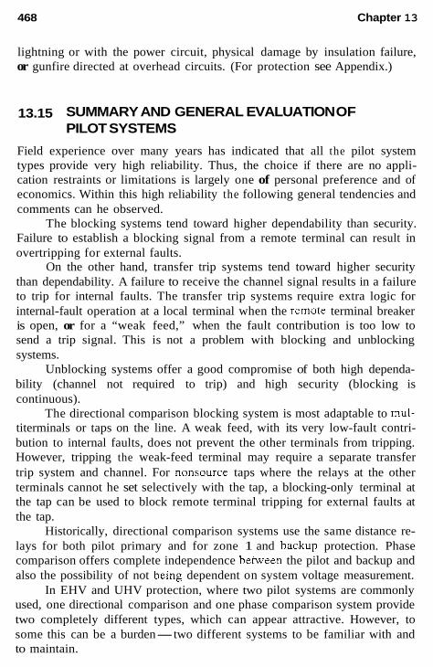
468 Chapter 13
lightning or with the power circuit, physical damage by insulation failure, or gunfire directed at overhead circuits. (For protection see Appendix.)
13.15 SUMMARY AND GENERAL EVALUATION OF PILOT SYSTEMS
Field experience over many years has indicated that all the pilot system types provide very high reliability. Thus, the choice if there are no appli- cation restraints or limitations is largely one of personal preference and of economics. Within this high reliability the following general tendencies and comments can he observed.
The blocking systems tend toward higher dependability than security. Failure to establish a blocking signal from a remote terminal can result in overtripping for external faults.
On the other hand, transfer trip systems tend toward higher security than dependability. A failure to receive the channel signal results in a failure to trip for internal faults. The transfer trip systems require extra logic for internal-fault operation at a local terminal when the remote terminal breaker is open, or for a “weak feed,” when the fault contribution is too low to send a trip signal. This is not a problem with blocking and unblocking systems.
Unblocking systems offer a good compromise of both high dependa- bility (channel not required to trip) and high security (blocking is continuous).
The directional comparison blocking system is most adaptable to mul- titerminals or taps on the line. A weak feed, with its very low-fault contri- bution to internal faults, does not prevent the other terminals from tripping. However, tripping the weak-feed terminal may require a separate transfer trip system and channel. For nonsource taps where the relays at the other terminals cannot he set selectively with the tap, a blocking-only terminal at the tap can be used to block remote terminal tripping for external faults at the tap.
Historically, directional comparison systems use the same distance re- lays for both pilot primary and for zone 1 and backup protection. Phase comparison offers complete independence between the pilot and backup and also the possibility of not being dependent on system voltage measurement.
In EHV and UHV protection, where two pilot systems are commonly used, one directional comparison and one phase comparison system provide two completely different types, which can appear attractive. However, to some this can be a burden-two different systems to be familiar with and to maintain.

Pilot Protection 469
Pilot-wire relays are rewmmended and widely applied for short lines such as exist in utility distribution and industrial plant complexes. Experi- ence over many years indicates that nearly all problems are pilot-wire re- lated, often the result of inadequate design, protection, or maintenance. When these are resolved, the performance is very high. Fiber-optic pilot circuits offer the advantage of having no electrical-related problems.
All types and combinations of pilot channels are in use. The choice is based primarily o n availability and economics moderated by personal pref- erence. Power-line carrier has been in use for many years and has the ad- vantage that the channel is under the control of the protection group or within the user company. However, available frequencies can be a problem, as the spectrum is crowded. Frequencies can be repeated within the system where interference does not occur. These RF frequencies are not licensed and so may be used by outside users in the area.
Microwave channels are used where they are available or justified for other uses. They are normally owned by the channel user.
Audio tones on leased or private-line channels have very good oper- ating records. It is very important that the leasing company be aware of the critical nature and requirements of protection channels.
It is interesting to observe again that all systems are in use. Where two pilot systems are applied, no one combination appears to predominate. All of which again emphasizes that relaying is largely a matter of “personality.”
BIBLIOGRAPHY
See the Bibliography at the end of Chapter 1 for additional information.
ANSIiIEEE Standard C37.93, Guide for Protective Relay Applications of Audio Tones Over Telephone Channels, IEEE Service Center.
Bayless, R. S., Single phase switching scheme protects 500 kV line, Transmission Distribution, 35, No. 1, 1983, pp. 24-29, 47.
Bratton, R. E., Transfer trip relaying over a digitally multiplexed fiber optic link, IEEE Trans. Power Appar. Sys t , PAS 103, 1984, pp. 403-406.
Chamia, M. and S. Liberman, Ultra high speed relay for EHV/UHV transmission lines-development, design and application, IEEE Trans., PAS-97, 1978, pp. 2104-2116.
Crossley, P. A. and P. G. McLaren, Distance protection based on travelling waves, IEEE Trans., PAS-102, 1983, pp 2971-2982.
Edwards, L., J. W. Chadwick, H. A. Riesch, and L. E. Smith, Single pole switching on WAS Paradise-Davidson 500 kV, line-design concepts and staged fault test results, IEEE Trans. Power Appar. Syst., PAS 90, 1971, pp. 2436-2450.

470 Chapter 13
IEEE Standard 281, Service Conditions for Power System Communications Appa- ratus, IEEE Service Center.
IEEE Standard 367, Guide for the Maximum Electric Power Station Ground Poten- tial Rise and Induced Voltage from a Power Fault, IEEE Service Cenfer.
IEEE Standard 487, Guide for the Protection of Wire Line Communication Facilities Serving Electric Power Stations, IEEE Service Center.
Shehab-Eldin, E. H. and P. G. McLaren, Travelling wave distance protection, prob- lem areas and solutions, IEEE Trans. Power Deliv., Val 3, July 1988, pp. 894- 902.
Sun, S . C. and R. E. Ray, A current differential relay system using fiber optics communication, IEEE Tram Power A p m ~ Sysr., PAS 102, 1983, pp 410-419.
Van Zee, W. H. and R. J. Felton, 500-kV System Relaying, Design and Operating Experience, CIGRE, 1978, Paper 34-7.
APPENDIX 1: PROTECTION OF WIRE-LINE PILOT CIRCUITS Optic-fiber channels eliminate the electrical hazards of induction, station ground rise, and insulation, which have been the major problem in the use of direct metallic wires. Still these channels are in use and will probably continue. Thus, a review of wire pilot-line protection is in order.
Surge arrestors can be used for equipment surge protection as appro- priate. Insulation problems generally can be detected by supervisory equip- ment together with good maintenance and inspection procedures. Mutual induction and station ground-rise voltages can be controlled by proper design.
The best pilot-wire channel is one with adequate insulation and shield- ing to withstand induced voltages or ground station rise if possible. Grounded metallic shields with pilot cables or supporting messenger wires can provide about 50% reduction in induced voltage.
Mutual induction occurs when fault current, primarily the 3/, compo- nent, flows through the transmission line that is in parallel with the pilot pair. An example is shown in Fig. A13.1-la. Avoltage equal to I,& (31,&) is induced in the pilot pair between the wires and ground. If the pilot pair
FIGURE A13.1-1 Typical voltage induction in a paralleled pilot circuit: (a) a pilot pair paralleling a transmission circuit; (b) mutual induction voltage profile for uniform induction and pilot pairs ungrounded a t both terminals; (c) mutual induction voltage profile for uniform induction and pilot pairs grounded a t bus H terminal; (d) mutual induction voltage reduced by circulation over the pilot pair and ground after protective g a p s flash over.

T
1Lb


Pilot Protection 473
TO RELAYS I C )
STATION
TWISTED PILOT PAIR
I INSULATED FROM STATION GROUND L CONNECTED TO REMOTE GROUND
I I I
LOW VOLTAGE AREA - TO REHOTE GROUND
c- LOW VOLTAGE AREA
HIGH VOLTAGE AREA HIGH VOLTAGE AREA TO REMOTE GROUND I TO STATION GROUND
V J
DURING GROUND FAULTS
~ d l RELAY INSULATING TRANSFORMER
NEUTRALIZING RXACTOR
Y - RELAYS
Y .. I I I I
STATION GROUND
TWISTED PILOT PAIR
I LOW VOLTAGE AREA- TO REMOTE GROUND HIGH VOLTAGE AREA / TO STATION GROUND
I t-- LOW VOLTAGE AREA TO STATION GROUND -
HIGH VOLTAGE AREA TO REMOTE GROUND
\ I Y
I DURING GROUND FAULTS
FIGURE A13.1-2 Continued

474 Chapter 13
If protective gaps at both ends break down, the induced voltage causes current to circulate over the two pilot wires in parallel and ground, and thus reduces the voltage to a low level. Telephone gaps, carbon blocks, and gas discharge tubes are used. With 3-mil gaps and gas tubes, typical breakdown voltages are 400-SO0 V, 6-mil gaps have breakdown of about 850 V.
For protective relay applications, it is mandatory that a mutual drainage reactor be used with the gaps or tubes. Typical connections are illustrated in Fig. A13.1-ld. These reactors force simultaneous breakdown of both gaps. Otherwise, the breakdown of one gap before the other will result in a mo- mentary voltage between the pair and is sufficient to cause undesired and incorrect operation of high-speed relays. As indicated, twisted pairs are nec- essary to keep this voltage difference between pairs to a small value.
Station ground rise is illustrated in Fig. A13.1-2. The return path for a ground fault is illustrated approximately in Fig. A13.1-2a. If the fault is within the area of the ground mat, most or all of the return current will be through the mat to the transformer bank neutral. For faults outside the ground-mat area, much or all of the current will return through the resistance represented by R, between the ground mat and remote ground. Rc is the summation of many parallel paths of contact between the station-grounding network and a nonuniform earth. Station-ground-mat design and its ground- ing is a complex subject with many variables and assumptions. The objective is to keep both the impedance across the mat and to remote earth as low as possible. Physical measurement of Rc is quite difficult.
During a ground fault there will be a voltage difference between the ground mat and remote earth of kI,R,. This can be quite large, with high values of current or ground resistance.
Equipment that enters the station from outside, such as communication cables, can be subject to this voltage, as illustrated in Fig. A13.1-2b. All grounded shield circuits should he terminated outside the station if there is the possibility af a significant voltage difference during faults. The pilot pairs that must enter the station will be subject to this voltage rise. Although the pair may not be grounded to remote earth physically, it can be essentially at remote earth potential by the distributed capacitance of the pair to earth. Generally, the rise is expressed as the maximum ZG(3Z0) current for a fault just outside the station times the measured or calculated ground resistance (RG). This represents a maximum value probably not realized in actual prac- tice. The insulation of the cable and associated terminating equipment must be able to withstand this rise, or neutralizing devices must be applied.
The two types of neutralizing transformers generally used are shown in Fig. A13.1-2c and d. In c the primary winding is connected between the station and remote earth to sense the station ground rise. This provides a neutralizing voltage across the secondaries so that the station terminals are

Pilot Protection 475
at the station-ground-mat voltage, while the other end is at remote ground. For multiple pilot pairs, transformers with many multiple secondaries are available.
A two-winding neutralizing reactor applicable to a single pilot pair utilized for protection is shown in Fig. A13-1-2d. Capacitor C1 with equiv- alent capacitance along the pilot pair or at the remote end provides the exciting current and, hence, voltage across the windings equivalent to the rise in station ground.
It is important to recognize that with these devices normally mounted in the station environment, one end will be at remote ground and so should be insulated and isolated from personnel contact. This would also be true of high-voltage cable entries without neutralizing devices. Pilot wires are usually limited to short distances, on the order of 15-20 mi or less.

Stability, Reclosing, and Load Shedding
14.1 INTRODUCTION
The emphasis in the preceding chapters has been directed toward the protection of the various components of the power system. Now we examine the operation of the power system as a whole or unit, how the protection is effected, and how relaying can be applied or modified to minimize system disturbances.
The normal operation of generating, transmitting, distributing, and us- ing ac electric power is of little concern to the protection systems as long as the load current does not exceed the specified maximums. Regulating relays and equipment are involved, but these are beyond the scope of this book. However, faults, system abnormalities, sudden increases or losses of large blocks of load or generation, and loss of equipment cause power sys- tem disturbances that can affect the protection. Also, incorrect application, setting, or operation of the protection can result in system disturbances and loss of service.
14.2 ELECTRIC POWER AND POWER TRANSMISSION
Power in an electrical system is
(14.1)
476

Stability, Reclosing, and Load Shedding 477
where P is the real power (W, kW, MW), Q the quadrature or reactive power (var, kvar, Mvar), V the phasor voltage (V, kV, MV), and f the conjugate phasor current (A, kA, MA), are the scaler magnitudes, with 0 the angle the current lags the voltage. Thus Q is positive for lagging reactive power, commonly designated simply as reactive power. Negative Q indicates leading reactive power. Power transmission across a system can he expressed in terms of sending-end power (P.< + jQ,s) and receiving-end power (PA +
For simplification it is practical to neglect the resistance and losses
and
j Q d .
over the system, so that
sin + (14.2) VSV, Pr = p* = p : - X
where V, and V , are the sending- and receiving-end voltages, + the angle by which V, leads V,, and X the total reactance between V, and V,.
Equation (14.2) can he plotted as shown in Fig. 14.1. At no-load across the system, V, = V,, + = O", and P = 0. The maximum power transfer occurs when + = 90" and is
(14.3) VSVK P,, = - X
Thus, more power can be transmitted between parts of the system by (1) raising the voltage V,, V,, or (2) reducing the reactance X, or a combi- nation thereof. The first is the logic for the higher-voltage systems (HV, EHV, UHV). The second is accomplished by more interconnecting lines or connecting series capacitors in the line. Both are in use in a variety of combinations.
14.3 STEADY-STATE OPERATION AND STABILITY
The normal operation of the power system involves an exchange of power between the generators and the various loads. In the typical simplified sys- tem of Fig. 14.1, V, and V, may represent the voltages developed by gen- erators supplying loads connected in the system, such as at buses G and H, or V, can represent the voltage of generators and V, the voltage of motor loads. Although the operations are similar in either one, the latter is easier to visualize. Assume an equilibrium state at a power level P' . With no losses the mechanical input PMs to the generators equals their output, PA. This is transferred across the system to equal the input P;, to the motors which, in turn, equals the mechanical output of the motors, PL,. Thus, before any fault and with all lines in service, the electrical transmission requirements of Fig. 14.lh show that V,, the voltage behind direct synchronous reactance, leads

478 Chapter 14
\ \ Breaker 1 üpen
W G L E 0'
FIGURE 14.1 Typical power-angie curves for a sirnplified two-machine power system: (a) system diagram; (b) power-angle curves for various sys- tem conditions.
V,, the motor interna1 voltage, by +'. As the load requirements cbange P' will increase or decrease and the system will adjust to a new operating angle +. Steady-state stability is the ability of the systern to adjust to gradual changes, and the limit is 90" for the two-machine no-loss system. Equation (14.3) defines the maximum power that the electrical system can transfer.
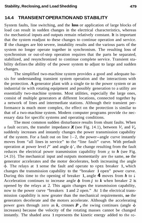
Stability, Reclosing, and Load Shedding
14.4 TRANSIENT OPERATION AND STABILITY
System faults, line switching, and the loss or application of large blocks of load can result in sudden changes in the electrical characteristics, whereas the mechanical inputs and outputs remain relatively constant. It is important that the system readjust to these changes to continue operation and service. If the changes are loo severe, instability results and the various parts of the system no longer operate together in synchronism. The resulting loss of synchronism or out-of-step operation requires that the parts be separated, stabilized, and resynchronized to continue complete service. Transient sta- bility defines the ability of the power system to adjust to large and sudden changes.
The simplified two-machine system provides a good and adequate ba- sis for understanding transient system operation and the interactions with the protection. A generator plant with a single tie to the power system or an industrial tie with rotating equipment and possibly generation to a utility are essentially two-machine systems. Most utilities, especially the large ones, consist of multiple generators at different locations, connected together by a network of lines and intermediate stations. Although their transient per- formance is much more complex, the effect on the protection is similar to that of a two-machine system. Modern computer programs provide the nec- essary data for specific systems and operating conditions.
The most common sudden disturbance results from shunt faults. When a fault occurs, the transfer impedance X (see Fig. 14.1), between V, and V,, suddenly increases and instantly changes the power transmission capability of the system. For a fault out on line 1-2, the power-angle curve instantly moves from “all lines in service” to the “line fault” curve. With prefault operation at power level I“ and angle 4‘. the change resulting from the fault reduces the electrical power transmission capability from g to h (see Fig. 14.lb). The mechanical input and outputs momentarily are the same, so the generator accelerates and the motor decelerates, both increasing the angle 4. The relays at 1 sense the fault and operate to open breaker 1, which changes the transmission capability to the “breaker 1 open” power curve. During this time to the opening of breaker 1, angle 4 moves from h to i. Acceleration continues to increase angle 4 from j to k when breaker 2 is opened by the relays at 2. This again changes the transmission capability, now to the power curve “breakers 1 and 2 open.” At 1 the electrical trans- mission capability is now greater than the mechanical requirements, so the generators decelerate and the motors accelerate. Although the accelerating power goes through zero as k, crosses P , the swing continues (angle 4 increases) because the velocity of the rotating masses cannot be changed instantly. The shaded area 1 represents the kinetic energy added to the ro-
479

480 Chapter 14
tating masses; area 2, kinetic energy returned to the circuit. Thus, the swing will continue to m, where area 2 equals area 1. At m the swing reverses, oscillating below and above the mechanical requirement, line P , with the final operating at n. This assumes no change in the power P’ requirements. The oscillation is damped by the resistance in the system, the voltage reg- ulator, and governor action.
The foregoing represents a stable system. If the area above the P‘ operating power line were less than area 1 below, the system cannot maintain synchronism and will go out of step. This represents an unstable system. Thus, it is desirable to keep area 1 as low as possible. This can be aided by fast relaying and breaker operation, and as discussed in Chapter 13, pilot protection provides this possibility. With high-speed simultaneous tripping and high-speed breakers, area 1 can be kept small, so that more power (P’) can be transferred across the system without it exceeding area 2 possibility.
The type and location of the disturbance is an important factor. In Fig. 14.lb system, the worse fault is a solid three-phase fault at bus G or bus H. In these situations, no power can be transmitted across the system during the fault. Usually, in a highly interconnected network, there will be multiple ties between V, and bus G, and between bus H and V,, so some power can be transferred for these three-phase solid faults. This is similar to a solid three-phase fault out on line 1-2, where the power-angle curve typically is as shown as “line fault.” As three-phase faults are not too common, stability studies often use the two-phase-to-ground fault as the criterion.
The time for + to change during system swings involves the solution of a second-order differential equation which includes the inertia constants or characteristics of the rotating masses. A common method is a step-by- step solution where during short-time intervals the accelerating power and angular acceleration are assumed to be constant. This provides a time-angle curve or data where if the system is stable the angle eventually decreases after the initial disturbance increase.
The voltages and currents during a system swing, particularly during out-of-step operation, are shown in Fig. 14.2. If we consider the simplified two-machine system, V, is considered fixed, with V, lagging relative to V,. For normal-load operation, V, will lag, as defined by the system power- angle curve and the loading.
As the result of a sudden large disturbance, V, can swing to as much as 120” approximately in a stable system. If the system is unstable, V, con- tinues to lag and, at 180” a “pole is slipped,” synchronism between V, and V, is lost, and the two parts operate out of phase. As a result, the voltage and current fluctuates. The electrical center is the point in the system where the impedance to the two sources is equal. At this center the voltage varies from maximum to zero, as shown by the locus circle. At other points the

Stability, Reclosing, and Load Shedding 481
FIGURE 14.2 Typical two-machine system voltages and currents as V, ro- tates relative to V,.
voltage varies from maximum to the diagonal line between V, and V, at 180". In the simple reactance system, the current changes from normal to about twice normal when V , and V,* are 180" out of phase. It should be recognized that during transient operation, the transient reactance of the machine is used rather than the synchronous impedance for normal-load operation. The difference in these values is large, but the effect on the total impedance between the rotating masses may or may not be appreciable. In general, for low- to high-voltage systems, most of the impedance is in the system, so the total X is not affected appreciably. However, in EHV and UHV systems with very large generating units, the effect is quite significant. In fact, in these systems the electrical center is often within the unit generator transformer or within the generator.
After a system disturbance, the rate of the swing and the voltage- current fluctuations is quite variable. At first the swing angle moves rela- tively fast, slowing down as the maximum angle is reached, and if the system is stable, stopping, then slowly changing to decrease the angle, thus oscil- lating with smaller angular changes until equilibrium is reached.
If the system cannot maintain stability, the angle changes slowly to close to 180", when a pole is slipped and a sudden large angular change occurs. This process is repeated with increasing speed each time a pole is slipped, until the system is separated.

482 Chapter 14
14.5 SYSTEM SWINGS AND PROTECTION
As a rule the phase-overcurrent relays should not operate on system swings and out-of-step operation. This is because this type of protection is normally applied in the lower-voltage parts of the system, at which the stability limits are seldom as critical, and that these relays are set well above load current. With the out-of-step currents not being too high, the relay-operating times at these low multiples would be long. If the out-ot-step condition were permitted to continue, there would be a possibility of the time-overcurrent relays "notching-up" and operating after repeated current peaks. Instanta- neous overcurrent relays that are normally set well above the maximum load may or may not operate on an out-of-step system swing.
Stability tends to be more critical in the higher-voltage systems. The reduced voltage and increased current during system swings appear as a variable impedance to the distance relays commonly applied for protection. This effect can be illustrated with the simplified two-machine system and the R- X diagram. In Fig. 14.3b the total system equivalent impedance after the fault is cleared by opening line 1-2 (see Fig. 14.la) is plotted between V, and V, on the R-X diagram. Arbitrarily, the origin is at a relay location such as 3 at bus G.
The locus of the system swing assuming IV,l = lV,/ is along a perpen- dicular line bisecting the line drawn between the V, and V,, points as shown. On this swing locus the impedance points at various angles between voltages V , and V, are the points of the corresponding angle between lines from points V, and V, and the swing locus. Thus on the IVsl = IV,i swing locus, impedance points are plotted for 60", 90", 120", 180", 240", and 270" angles that V, lags V,. The impedances "seen" by distance relays 3 at bus G and relays 4 at bus H are the phasors from points G and H, respectively, to the locus line. The change in this impedance is relatively slow and variable, as discussed earlier.
If V, lags V,, the normal load is in the second quadrant, rather than the first quadrant, and the swings move from left to right.
Actual swing curves are more complex and are arcs of curves that are functions of the difference in V, and V, magnitudes, system impedance and voltage variables, governor and regulator actions, and so on. Typical swing locuses for the differences in the two source voltage magnitudes are illus- trated in Fig. 14.3b. In actual practice, the swing impedance as seen from any given relay may be anywhere in the four quadrants and move in any direction during a swing segment. With the disturbance usually resulting from a fault, there can be a major shift of the impedance seen by the relays as the fault is cleared to change the transfer impedance (as illustrated in Fig. 14.lb) across the system. Computer studies provide more accurate infor-

Stability, Reclosing, and Load Shedding 483
(., H
\ , , R
-x
FIGURE 14.3 Typical impedance swing loci for the simplified two-machine system after a fault is cleared: (a) system of Fig. 14.la after line 1-2 is opened to clear fault; (b) typical distance relay settings at 3 bus G and the system-swing loci after faulted line 1-2 opened.
mation for specific systems and conditions and should be used for deter- mining relay operation, settings, and applications.
However, the R-X diagram scenario is similar for all cases. Plotting only a specific line impedance under consideration on the R-X diagram (since the impedance behind each line bus will vary with switching), normal operating conditions (load) should appear as impedances outside the relay
'OCUI
: IVRI

484 Chapter 14
operating characteristics. Normally, for the relay at the origin, load into the line is in the first quadrant, load out of the line is in the second quadrant.
When a system disturbance occurs, the impedance changes instantly. If the fault is the disturbance and is within the line under consideration, the impedance seen by the distance relays moves into their operating zone, and the line is tripped. If the disturbance is outside the line under study, the impedance seen instantly shifts to a new location somewhere in the four quadrants. During a fault, there is a small swing period, then another shift as the two line breakers clear the fault. If the breakers do not open simul- taneously, there will be the swing during the fault, an instant shift to a new location when one breaker opens, another small swing change, then an in- stant shift to still another location as the second breaker opens. With the fault now cleared, the swing continues, typically as illustrated in Fig. 14.3b. For the example of Fig. 14.1 the swing is assumed to start, as shown in Fig. 14.3b, at about an angle 6 of 50", which corresponds to the point 1 angle in Fig. 14.lb.
If the system is stable, the impedance locus will move with decreasing speed to about SO", which corresponds to point m in Fig. 14.lb, and where area 1 = area 2. Then the impedance phasor momentarily stops, reverses, and moves out to the right. Eventually, after short oscillations, a new equi- librium is reached at which the system will operate until the next load change or disturbance occurs.
If stability is lost, the impedance phasor will move beyond the 80" point in the example to 180", where a pole is slipped and the two parts now operate out of synchronism. The impedance change generally slows down to the 180" point, then moves rapidly to the left and back to the right to pass through the 180" point again, unless the two parts are separated some- where. As indicated earlier, generally systems can swing on a transient basis to near 120" and remain stable.
Thus, distance relays that respond to balanced three-phase conditions and faults will operate when the swing or out-of-step impedance phasor moves into and remains long enough within their operating characteristic. Directional comparison pilot systems utilizing phase distance fault detectors are also subject to operation as a swing phasor impedance moves through their operating zone. Phase comparison pilot systems operating on current magnitudes are not subject to operation on swings and out-of-step conditions.
The swings shown in Fig. 14.3 are typical of the events after a fault has occurred and been cleared. Two examples of the complete scenario from the occurrence of a fault are shown in Figs. 14.4 and 14.5. Both plot the impedance changes at a 115-kV-relay location in highly interconnected
Stability, Reclosing, and Load Shedding
115 kV System- 500 kV System
485
FIGURE 14.4 A 500-kV fault that caused the 115-kV system to lose synchronism.
power network that resulted from a fault on a 500-kV-transmission line. The system diagram is an abbreviation of a complex network.
For fault 1 (see Fig. 14.4) the impedance seen by the relay before the fault (initial operating point: time 0) is at the far left. Load was flowing from B to A on the 115-kV line. At the instant of the fault, the impedance instantly changes to the right (fault occurs: time 0). In other words zero time is represented by the broken lines. A swing occurs for 0.067 s (four cycles)

Chapter 14
115 kV Svstem 500 kv System
FIGURE 14.5 (a) A 500-kV fault for which the 115-kV system was able to maintain stability; (b) enlarged arcs are shown for the 115-kV system's re- covery from the 500-kV fault.

Stability, Reclosing, and Load Shedding
x
4137
R
R a n d x in per unit at 100 PNA. 115 kV.
FIGURE 14.5 Continued
when the near breaker trips with another instant change. Then the swing continues for 0.083 s (five cycles) until the far breaker opens. The fault is now clear, hut the system has been disturbed so continues swinging, as shown by the heavy line from left downward to the right. At the beginning, the swing is fairly rapid, but slows down as it approaches the 180" point, at which a pole is slipped and synchronism is lost. The swing then speeds up and the system would continue to operate out of synchronism, moving faster and faster at a variable rate until a separation is made.
At 0.40 s the near breaker was reclosed in an attempt to restore the line to service. This was unsuccessful, the breaker retripped and the swing continued.
For fault 2 (see Fig. 14.5), the same events occur; fault occurs, near breaker trips in four cycles, remote breaker trips in five cycles, system con- tinues to swing slow at first, slowing down and, as illustrated in the enlarged diagram (see Fig. 14.5b) stops, turns around, and moves to a new stable operating point. Thus synchronism is not lost, and the system recovers and continues to operate.

488 Chapter 14
The near breaker was reclosed at 0.416 s (25 cycles), but retripped as shown.
14.6 OUT-OF-STEP DETECTION BY DISTANCE RELAYS
From the previous discussion, the "handle" for relay detection of out-of- step conditions is the rate of impedance change seen by distance relays. Detection can be accomplished with two distance units, one set for a longer reach and essentially surrounding a unit set with a shorter reach. With this combination a fault falling within the operating zone will operate both units essentially simultaneously. However, a swing that occurs within their oper- ating zones will first operate the outer or longer-reach-set unit and, as it progresses, later operate the inner or shorter-reach-set unit. Logic is ar- ranged so that output will occur only for a sequential operation of the two distance units. Typically, an out-of-step condition is indicated when the time difference between the two distance units' operation is approximately 60 ms or more, with a typical distance unit setting about 20-30% apart. The two types most commonly applied are illustrated in Fig. 14.6. These distance relay characteristics were described in Section 6.5 (see Fig. 6.13).
The concentric circle application is generally applicable to the shorter lines up to about 100 mi, and where the outer circle 21,,, can he set not to operate on the maximum load impedance phasor. On long and heavily loaded lines, the blinder type generally will he required for line protection as well
- 10s outer Unit
1 p Inner u n i t
21p *nner ""it
210s outer U"lt
-R
Indicates
-R - \
/ I -x
FIGURE 14.6 Typical distance units applied for out-of-step detection: (a) con- centric circle type; (b) double-blinder type.

Stability, Reclosing, and Load Shedding 489
as swing detection, to provide extended reach for the line with restricted tripping for loads.
Application of out-of-step relays is complex, depending on system fac- tors, operating practices, and individual protection philosophies. As a result, there is little uniformity among the utilities. However, the basic objectives are the same.
1. Avoid tripping for any disturbance for'which the system can re- cover. Thus, relay operation should not occur for all stable swings. Stability studies can provide the minimum impedance the relays will see for stable operation, so that the phase distance relays can be set to avoid operation on these impedance values. For unstable system operation, it is mandatory to separate the sys- tem, such that after it goes out of step it cannot recover without separation. This separation preferably should be done at a point where (a) the generation-load balance will permit the parts to con- tinue service temporarily, and (b) at a convenient location where the parts can be resynchronized and reconnected. Usually, these requirements will be in conflict with a, varying depending on the system operation at the time of the disturbance. As a result, con- siderable compromise and judgment is required; there are no easy answers.
2.
In the past, the general practice was to apply out-of-step blocking in the transmission system. The aim was to keep the system intact to avoid possible long delays after a system disturbance in having to reconnect the various lines that may have opened. In practice, it is doubtful that many line circuits would be invohed and trip during a system disturbance. Thus, the trend seems to be toward more out-of-step blocking of automatic reclosing after the line relays operate, as this only adds more "shock" to an already disturbed system.
Out-of-step tripping has not been used widely over the years, but is receiving considerably more attention, particularly with very large generator units connecting into EHV and UHV networks. The higher generator reac- tances and lower inertia constants have reduced critical clearing times. Thus, stability limits tend to be more critical and early separation more important should the system become unstable.
On the other hand, opening a circuit breaker when the two parts of the system are essentially 180" apart may result in breaker damage. This is because of the high recovery voltage across the breaker contacts when in- terrupting near 180" between V, and V,,. An ANSI standard specifies that out-of-phase switching breakers must be able to intempt a current 25% of the rated interrupting current with a recovery voltage of 3.53 pu rated line-
490 Chapter 14
to-neutral voltage. Various out-of-step tripping schemes are available to de- tect out-of-step conditions as the impedance phasor moves into the operating areas, such as shown in Fig. 14.6, but to inhibit breaker tripping until the out-of-step swing impedance phasor passes out of the outer unit Zl,,x. At that time the angle of V, and V, is less than 180" and decreasing to a more favorable angle for breaker interruption.
Specific and additional information on the application and details of available schemes for line and generator out-of-step indication and protec- tion should be obtained from the various manufacturers.
14.7 AUTOMATIC LINE RECLOSING Somewhere close to 80, to as high as 90% of faults on most overhead lines are transient. These result principally from flashover of the insulators by high transient voltages induced by lightning, by wind causing the conductors to move together to flashover, or from temporary tree contact, usually by wind. Therefore, by deenergizing the line long enough for the fault source to pass and the fault arc to deionize, service can be restored more expedi- tiously by automatically reclosing the breaker. This can significantly reduce the outage time, to provide a much higher service continuity to customers. However, it is important to recognize that automatic reclosing without checking synchronism should be done only (1) if there are sufficient other interconnections to hold the separated parts in synchronism, or (2) if there is a synchronous source at only one terminal, with none at the others.
Reclosing can be one single attempt (one-shot) or several attempts at various time intervals (multiple-shot), The first attempt may be either "in- stantaneous" or with time delay. Instantaneous here signifies no intentional time delay, during which the circuit breaker closing coil is energized very shortly after the trip coil has been energized by the protective relays. This is accomplished by a high-speed (52bb) auxiliary switch on the circuit breaker that closes as soon as the breaker mechanism starts moving to open the main interrupting contacts. Thus, both the trip and close coils are ener- gized essentially together; consequently, the breaker contacts are open for only a very short time. The time from energizing the trip coil to the reclosing of the breaker contacts on an instantaneous reclose cycle is a function of the breaker design: typical values are 20-30 cycles. Generally, this is suf- ficient to permit the fault arc to deionize during the period when the circuit is open. Long experience has indicated that in a three-phase circuit, on the average the deenergized (open or dead) time for the fault arc to deionize and not restrike is
f=- kV + 10.5 cycles 34.5
(14.4)

Stability, Reclosing, and Load Shedding
This formula applies where all three phases are opened and there is no trapped energy, such as from shunt reactors, or induction from parallel lines. For single-pole trip-reclose operation, longer deionizing times are required, for energy coupled from the unopened phases can keep the arc active. The deionizing times can be increased by 250%.
Many varieties of reclosing relays (79) are available with varying de- grees of sophistication for single and multiple shots. After their cycle of operation, if reclosures are successful at any point, they reset after a preset time interval. If reclosure is unsuccessful, they move to a lockout position so that no further automatic operation is possible. After service is restored by manual operation of the circuit breaker, the reclosing relays reset after a time delay. This is to prevent an automatic reclose operation should the breaker inadvertently be closed manually with a fault still existing on the line.
As many stations and substations are unattended and are operated by various remote control systems, the reclosing requirements can be pro- grammed into the automation and controlled from a central dispatch office. A few operations of this type are now in service.
Reclosing practices are quite variable, depending on the type of circuit and individual company philosophies. A brief review will outline the more common practices.
491
14.8 DISTRIBUTION FEEDER RECLOSING
For an overhead radial feeder without synchronous machines or with mini- mum induction motor load, fast reclosing at the source offers a relative high probability of rapid restoration of service. The almost universal practice for these types of circuits is to use three and occasionally four attempts to restore service before locking out. Subsequent energizing is by manual closing. Generally, the first reclose is instantaneous, the second about 10-20 s after retrip, the third attempt about 20 to as much as 145 s after retrip. Specific times vary widely. When applying four reclosure attempts, the times between them are smaller.
Reclosing is generally not used for underground feeders, because cable faults are more inclined to be permanent. Reclosing is used in practice for combination overhead-underground circuits, with more inclination to use it when the percentage of overhead to underground is high.
For industrial ties with large motor loads or synchronous machines and for ties connecting “cogeneration” sources, care is required that reclosing at the utility substation does not cause damage to the rotating equipment. Generally, the connections are by single-circuit ties, so that during the open period the two parts will be operating independently of each other. Reclosing

492 Chapter 14
then will connect the two parts together out of phase, resulting in power surges and large mechanical shaft torques that can cause severe damage.
With synchronous machines, reclosing must he delayed until the ma- chines are removed from the circuit; then reclosing can restore voltage and pick up the static and nonsynchronous loads at the station. This can be accomplished by over- and underfrequency relays with under- and overvol- tage relays. Transfer trip should be used to disconnect islanded machines that can carry load connected to them in the island.
For induction motors, reclosing should not take place until their resid- ual voltage has decreased to 33% of rated value. In general, the induction motor voltage decreases very rapidly, for there is no field to supply excitation.
Joint cooperation is very important with these types of intercon- nections.
Where there are multiple fused taps off a distribution feeder, a common application is to apply an instantaneous trip unit set to overreach these fuses out to the first main feeder sectionalizing point. Fast reclosing is then used and, if unsuccessful, further operation of the low-set instantaneous relays is blocked. With the higher percentage of transient faults, this prevents the fuse from operating should the fault be on the down side of the fuse, thereby minimizing long delays in fuse replacement. If the fault is permanent, the fuse will clear faults within their operating zone and range. This is known as fuse-saving and is covered in Section 12.6.
14.9 SUBTRANSMISSION AND TRANSMISSION- LINE RECLOSING
Circuits used to transfer power between stations require reclosing of both terminals to restore service. This can be done at high speed only if there are sufficient parallel ties in the network to provide an exchange of power be- tween the two parts of the system. This is necessary to hold the source voltages in synchronism and essentially in phase during the line-open period. This reclosing requires high-speed simultaneous tripping of the line and so is limited to circuits protected by pilot protection. If this protection is not used or is out of service, fast reclosing should not be used or should be blocked.
Where the effectiveness of the parallel ties is in doubt, several reclos- ing possibilities exist:
1. 2.
Single-pole pilot trip and reclose: This is described in Chapter 13. With pilot relay protection for simultaneous line tripping, reclose one end instantaneously and the other end after a check to ensure

Stability, Reclosing, and Load Shedding 493
that the line and bus voltages are synchronous and within a preset angle difference. Synchroverifier (25) relays operate when the “beat” frequency across an open breaker is within prescribed lim- its, the two voltages on either side are of sufficient magnitude, and the angle between them within a preset value. Typical angle ad- justments are about 2Oo-6O0. Without pilot protection, or when preferred, reclose with (a) live line, dead bus; (b) dead line, live bus, or (c) live line, live bus with synchrocheck. It is desirable to operate these through reclos- ing relays to avoid potential breaker “pumping.”
3.
Different combinations for reclosing are applicable and depend on the operating and the system requirements.
The successful reclosing of both terminals of a line increases area 2 availability (see Fig. 14.lb) by moving from the “breaker 1 and 2 open” curve to the higher “all lines in service” curve shortly after point 1. This aids stability. On the other hand, if reclosing is not successful, such as for a permanent fault, area 1 is increased by the additional fault and retrip time operation along the low “line-fault” curve. Area 2 is also reduced, so that the stability limit is reduced, because area 2 = area 1 at a much lower an-
However, because most line faults are transient and the stability limit is frequently never reached, simultaneous instantaneous reclosing is widely used for lines of 115 kV and up. Generally, only one attempt is made, but occasionally subsequent attempt(s) are made with the voltage check or synchrocheck equipment outlined in the foregoing. Again, this is only for overhead lines. Transmission cable circuits are not reclosed. For overhead-cable combinations, separate protection is sometimes used for the cable and overhead section, with reclosing permitted for the overhead line faults only.
Questions have been raised about the application of instantaneous re- closing at or near large generating stations. This is because of the potential damage to the long turbine shafts of large modern turbine generator units. An example is a solid or near-solid three-phase fault near or at a generator bus. This reduces the voltage of the three phases essentially to zero, so that no power can be transferred until the fault is cleared. Even with very fast relaying and circuit breakers, the voltages on the two sides of the breaker are at a different angle, so reclosing results in a sudden shock and movement of the rotor and to transient oscillations and stresses. These are cumulative; hence, actual known damage may occur some years in the future. Past ex- perience has not documented any large amount of damage, but this remains
gle 0.

494 Chapter 14
as a potential worry. Some utilities are removing reclosing near large gen- erator stations; others are not. The issue is a very difficult one, and is one not easily resolved. It is further complicated because the most severe types of faults (three-phase- and two-phase-to-ground) occur rather infrequently. Thus, perhaps the cumulation of the stresses will not exceed a critical dam- age point during the equipment lifetime. In the meantime, more benefits of reclosing are obtained.
This raises another difficult question: How far apart can the voltages be before damage and problems with stable operation occur? Out in the system, voltage differences on the order of 60" or more have existed before reclosing, and reclosing has been successful. Here the system impedance network can absorb this large difference. This would not be tolerated near a generating unit. It has not been possible to provide general limits, as each application depends on the specific system.
Reclosing on multiterminal lines is more complex, especially if more than two terminals have synchronous voltage sources. It may be practical to reclose one or two terminals instantaneously and the others after voltage or synchrocheck. Where the transmission line has load taps, such that it serves the dual function of transmission and distribution, circuit reclosing of the source terminals can facilitate service to the tap loads as long as no syn- chronous equipment is involved. In these circumstances, the requirements outlined earlier under distribution feeder reclosing also apply.
14.10 RECLOSING ON LINES WITH TRANSFORMERS OR REACTORS
Lines that terminate in a transformer bank without a breaker between them, or lines with shunt reactors, should not be reclosed automatically unless it can be assured that the fault is in the line section. Differential or transformer reactor protection can be used to block reclosing at the local station, with transfer trip to block the remote station. This generally means some delay in reclosing to ensure that the trouble is not in the transformer or reactor. If the line protection excludes the transformer bank, this protection can only initiate reclosing. Breakers are not generally used with shunt reactors, so the protection zone for the line would include the reactors.
Transformers are sometimes connected to a line through a motor-op- erated air-break switch. For faults in the transformer, the protection trips the low-side transformer breaker, initiates a remote trip by a grounding switch or transfer trip channel, and opens the air switch. Reclosing of the remote terminal(s) may be initiated after a coordinating time delay for the air switch to operate. This may be supervised by receipt of the remote trip signal.

Stability, Reclosing, and Load Shedding
14.11 AUTOMATIC SYNCHRONIZING
This equipment can be applied for automatic synchronizing at attended or unattended stations, or to assist manual synchronization. It does not adjust the two separated systems, but will program closing as the voltages arrive in-phase when the frequency difference is small. The synchroverifier type is not recommended for this service, but has been used for small machines on the order of 500 kVA.
495
14.12 FREQUENCY RELAYING FOR LOAD SHEDDING-LOAD SAVING
The primary application of underfrequency relays is to detect overload. Load shedding or load saving is the attempt to match load to the available generation after a disturbance that has left a deficiency in the generation relative to the connected loads. Thus, the overloaded system or part of a system (island) begins a frequency decay that, if not halted, can result in a total system shutdown, such as was experienced in the 1965 Northeast black- out. Generating plants generally cannot operate below 56-58 Hz (60-Hz base).
Normal load changes and moderate overloads can he absorbed by the spinning reserve in the system, for all the generators are usually not oper- ating at full capacity. Thus, these overloads result in small increments of reduced speed and frequency that activate the governors to increase the prime-mover input. As has been outlined earlier, transient changes, such as those that result from faults, involve the exchange of kinetic energy of the rotating masses to the system until the system can readjust to a new equilibrium.
When the load requirements significantly exceed the generation ca- pabilities, the frequency of the system decreases. The power system can survive only if enough load is dropped until the generator outputs equal or are greater than those of the connected loads. This imbalance most often results from the loss of a key or major transmission line(s) or transformer(s) that are involved in a major transfer of power either within the system or between two interconnected systems. The causes can be faults cleared with- out high-speed reclosing, incorrect or accidental relay or manual operations, or other situations that interrupt large power flows.
The rate at which the frequency drops is a variable function with time, depending on the amount of overload, the system inertia constant, and the load and generator variations as the frequency changes. This is covered in detail in the articles by Dalziel and Steinbach and Berry et al. in the Bibliography.

496 Chapter 14
The handle to detect these problems is underfrequency or the rate of frequency decline in the power system. In a large system, rhere can be an almost infinite number of possibilities that can result in load-generator im- balance, so it becomes difficult to determine quickly and accurately where and what action should be taken. The present practices are to apply under- frequency relays at various load points set to progressively remove load blocks until the frequency decay is stopped and returns to normal. Generally, underfrequency is used, but rate of change of frequency has some use.
Any measurement at one point in the system, as is with underfrequency or rate-of-change relays, is an approximation of the problem. As a result, generally more load than may actually be necessary is probably shed, hut it is far more imporrant to avoid a massive shutdown.
It is desirable to locate the relays throughout the system to minimize possible “islanding” and heavy power flows. They are set at different fre- quency levels to trip varying amounts of load. General practice h a been to use three frequency steps between about 59.8 and 58 or 57 Hz (60 Hz normal), although as many as five steps have been applied. As far as pos- sible, nonessential loads are removed first, sometimes with rotation among different loads.
The early frequency relays (81) were electromechanical, with present relays of the digital type. The latter operate by counting the zero crossings of the filtered ac system voltage, and are extremely accurate.
Frequency relays can he used to restore or supervise the restoration of load after the system is stabilized and generation capability is available to meet the dropped load. If load restoration is done automatically, the loads should be added in small increments, with sufficient time intervals for the system to adjust, to avoid reversion to reduced frequency.
The application and setting of underfrequency relays is not standard- ized and, for the large systems, is based on a study of the most probable and worst-case possibilities, seasoned with general experience and judgment. For interconnected systems, such as exist in US. power pools, i t is important that a common pool program he developed and implemented through the interconnected systems. This can involve separating the system when a heavy power interchange occurs that is unfavorable to an undisturbed system.
The present wide use of load shedding has both prevented many hlack- outs and limited some to small areas with minimum outage times. However, not all possibilities can he anticipated, so blackouts will continue to occur, one hopes quite limited, and for very short outage times.
Ultimately, perhaps, multiple measurements across the system can be sent to a central location for a programmed analysis of the problem, with solutions quickly dispatched to the proper locations for rapid matching of
Stability, Reclosing, and Load Shedding 497
load and available generation. It appears that this will involve considerable data and communication facilities operating at high speeds.
14.13 FREQUENCY RELAYING FOR INDUSTRIAL SYSTEMS
In general, one underfrequency step is sufficient,for the industrial ties that have local generation. The relays would trip loads on the loss of the utility supply, so that the remaining loads match the local generation capability. In this manner, the most essential load for the plant can be maintained. The very rapid decline of frequency when the loads are large relative to the local generation probably makes more than one step of underfrequency relaying impossible.
It may be desirable to supervise plant load shedding with an under- current relay in the utility tie. This would prevent a utility frequency dis- turbance from necessarily shedding plant load as long as the tie is closed and the utility is able to restore frequency by shedding other, low-priority loads. The undercurrent relay operates to permit local load shedding only when the tie current (or power) is below a set value. A reverse power relay to measure power flowing from the plant to the utility may be necessary to prevent the local generator from supplying power to other loads connected on the same feeder when the utility substation breaker is open.
BIBLIOGRAPHY
See the Bibliography at the end of Chapter 1 for additional information.
Berry, Brown, Redmond, and Watson, Underfrequency Protection of the Ontario Hydro System, CIGRE, 1970, Paper 32-14.
Daldel, C. E. and E. W. Steinbach, Underfrequency protection of power systems for system relief, load shedding system splitting, IEEE Trans. Power Appar Syst., PAS 78, 1959, pp. 1227-1238.
IEEE Power System Relaying Committee Working Group, A status report on meth- ods used for system preservation during underfrequency conditions, IEEE Trans. Power Appar Syst., PAS 94; 1975, pp. 360-366.
IEEE Power System Relaying Committee, Automatic reclosing of transmission lines, IEEE Trans. Power Appar. Sysr., PAS 103, 1984, pp. 234-245.
Lokay, H. E. and V. Burlnyk, Application of underfrequency relay, for automatic load shedding, IEEE Trans. Power Appar. Syst., PAS 87, 1968, pp. 776-783.
Power Systems Engineering Committee, Proposed terms and definitions for power system stability, IEEE Trans. Power Appar Sysr., PAS 101, 1982, pp. 1894-1898.

Problems
These practical problems, developed over many years from actual experi- ence, provide the opportunity to apply the material in the book by practicing the basic techniques. Problems involving application choices are generally so subjective that I have avoided them whenever possible. Each problem has a “message” to be unlocked with a reasonable minimum of labor- that is, with a good RH factor, where R equals relative minimum labor and H equals high educational value.
CHAPTER 2
2.1 A wye-connected generator has a nameplate rating of 200 MVA, 20 kV, and its subtransient reactance (Xl;) is 1.2 pu. Determine its reac- tance in ohms. The generator of Problem 2.1 is connected in a power system where the base is specified as 100 MVA, 13.8 kV. What is the generator reactance (Xi) in per unit on this system base? Convert the per unit answer calculated in Problem 2.2 to ohms. Does this check the value determined in Problem 2.1? Three 5 MVA single-phase transformers, each rated 8:1.39 kV, have a leakage impedance of 6%. These can be connected in a number of different ways to supply three identical 5 ohm resistive loads. Various
499
2.2
2.3
2.4

500 Problems
TABLE P2.4 Total i' as
Line-to Iine viewed from base hV the high side Load Transformer connection connection Load R
to in per Per Case No Primary Secondary secondary HV LV unit unit Ohms
1 Wye Wye Wye
3 Wye Delta Wye
5 Delta Wye Wye
7 Deita Delta Wye
2 Wye Wye Delta
4 Wye Delta Delta
6 Deita Wye Delta
8 Delta Delta Delta
transformer and load conneciions are ouilined in the Table P2.4. Com- plete the table columns. Use a three-phase base of 15 MVA. A three-phase generator feeds three large synchronous motors over a 16 km, 115 kV transmission l h e , through a transformer bank, as shown in Fig. P2.5. Draw an equivalent single-line rcactance diagram with a11 reactances indicated in per unit of a 100 MVA, 13.8 kV or 115 kV base.
2.5
Tranrformer :I Transformer 12 I
. . . . x;=20,
FIGURE P2.5
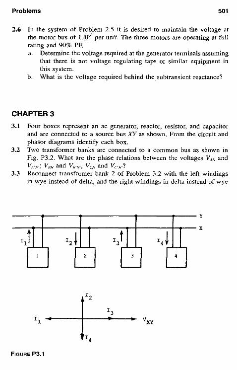
Problemç 501
2.6 In the system of Problem 2.5 it is desired to maintain the voltage at the motor bus of i.@" per unit. The three motors are operating at full rating and 90% PF. a. Determine the voltage required at the generator terminals assuming
that there is not voltage regulating taps or similar equipment in this system. What is the voltage required behind the,suhtransient reactance? h.
CHAPTER 3 3.1 Four boxes represent an ac generator, reactor, resistor, and capacitor
and are connected to a source hus XY as shown. From the circuit and phasor diagrams identify each hox. Two transformer hanks are connected to a common hus as shown in Fig. P3.2. What are the phase relations hetween the voltages V,,, and V,.,.; V,, and V,.,., V,, and i',-.,.? Reconnect transformer bank 2 of Problem 3.2 with the left windings in wye instead of delta, and the right windings in delta instead of wye
3.2
3.3
FIGURE P3.1

502 Problems
Transformer Bank N o . 1
BUS
A
B
C
-
0. 2 A'
B '
Transformer El= C '
=
FIGURE P3.2
so that VAN and V,.w are in phase, V, and V,,,,r are in phase, and V, and Vvw are in phase. The power transformer connections shown in Fig. P3.4 are nonstandard and quite unusual with today's standardizatiori. However, this connec- tion provides an excellent exercise in understanding phasors, polarity, and directional sensing relay connections.
Connect the three directional phase relays A , 5, C to lineside CTs and bus-side VTs for proper operation for phase faults out on the line. Use the 90"-60" connection. Each directional relay has maximum torque when the applied current leads the applied voltage by 30". The auxiliary VTs should be connected to provide the relays with equiva- lent line side voltages.
3.4

Problems 503
BUS a a b b c c
c
Y 4 - - -*ux. V T S .+ c A
B !! c
CT I
A B C Line
FIGURE P3.4
CHAPTER 4
4.1 The per-unit currents for a phase-a-to-ground fault are shown in the diagram. Assume that the system is reactive with all resistances ne- glected, and that the generator(s) are operating at j 1.0 per unit voltage.
Draw the positive, negative, and zero sequence diagrams and describe the system that must exist to produce the current flow as shown. For the system shown in Fig. P4.2: a. Determine the source and equivalent star reactances of the trans-
former on a 30 MVA base. b. Set up the positive, negative, and zero sequence networks. There
are no fault sources in the 13.8 and 6.9 kV systems. Reduce these networks to single-sequence reactances for faults on the 13.8 kV side.
4.2

504
B u s G
.
Problems
B u s H
- 2 Fault c i - 6
e l -1 - 1 - 1
.,
J3 - - -
- 2 Fault c i - 6
e l -1 - 1 - 1
J3 - - -
.,
FIGURE P4.1
c.
d.
e.
f.
g.
h.
For the system shown in Fig. P4.3: a.
Calculate a three-phase fault at the 13.8 kV terminals of the transformer. Calculate a single-phase-to-ground fault at the 13.8 kV transformer terminals. For the fault of part d, determine the phase-to-neutral voltages at the fault. For the fault of part d, determine the phase currents and the phase- to-neutral voltages on the 115 kV side. For the fault of part d, determine the current flowing in the delta winding of the transformer in per unit and amperes. Make an ampere-turn check for the fault currents flowing in the 115 kV, 13.8 kV, and 6.9 kV windings of the transformer.
Determine the current flowing to the load. Assume that the gen- 4.3
30 MVA
o i l 5 k V ]]] 13.8kV
6.9kV
A4 & W A S , = 600
- l6i on 30 MVA = 22.5% on 15 MVA
'115-13.8- '115-6.9 Xi3.8-6.9= 11% on 10 MVA
FIGURE P4.2

Problems
13.8kV Bus
505
Load Bus
Eqo ~ ,
MVASC = 312.5
Source
X = X = j0.42 pu 4 MVA Load @ 0 . 9 PF X2 = 0.15 pu x = m
@ 4 MVA
X = j1.26 pu
on 100 MYA Base Z o = 11.93 Lko PU 0 on 100 MVA Base
FIGURE P4.3
erators of the equivalent source behind the 13.8 kV bus are op- erating at 1 per unit voltage at 0". Calculate the voltage at the load bus. Calculate the fault current for a solid phase-a-to-ground fault at the load bus. Neglect load for this part. Calculate the currents flowing in the line when an open circuit occurs in the line just at the load bus. Assume phase a opens while carrying the load as indicated. Calculate the currents flowing when the open phase of a conductor of part d falls to ground on the source side of the open. Assume a solid fault.
f. Repeat part e but for the case when the opened conductor falls to ground on the load side.
Repeat the example of Section 4.14 for a solid phase-to-ground fault on the 161 kV terminals of the autotransformer. Compare the directions of the currents in the bank neutral and the tertiary with those for the fault on the 345 kV side.
b. c.
d.
e.
4.4
CHAPTER 5
5.1 A 13.8 kV feeder circuit breaker has a 6005 multiratio current trans- former with characteristics as shown in Fig. 5.10. The maximum load on the feeder is 80 amp primary. Phase time inverse overcurrent relays are connected to the CT secondaries. The relay burden is 3.2 VA at the tap values selected, and the lead burden is 0.38 ohm.

506 Problems
a. If the 1005 CT ratio is used, then a relay tap of 5 amp is required in order for the relay pickup to he 125% above the maximum load. With these, determine the minimum primary current to just operate the relays. For the selection of part a what is the approximate maximum sym- metrical fault current for which the CTs will not saturate (use the ANSI/IEEE knee point)? If the 200:5 CT ratio is used so that the 2.5 amp relay tap can he used, determine the minimum primary current to just operate the relays. Repeat part h for the selection of part c.
recommend?
h.
c.
d. e. Which of these two CT and relay selections would you
Determine the minimum CT ratio that might he used with a 0.5-2.5 amp ground relay with an instantaneous trip unit set at 10 amp. The total ground relay burden is 285 VA at 10 amp. See Fig. 5.10 for C T characteristics. A circuit has 8005 wound-type CTs with characteristics as shown in Fig. 5.7. The maximum symmetrical fault for which the associated relays are to operate is 15,200 amp. Approximately what will he the error in percent if the total connected burden is 2.0 ohms? If it is 4.0 ohms? The feeder of Problem 5.1 has a ground relay connected in the CT circuit which has a burden of 4.0 VA at tap value. The taps available are 0.5, 0.6, 0.8, 1.0, 1.5, 2.0, and 2.5, which represent the minimum pickup current. What is the maximum sensitivity that can be obtained in primary amperes for a phase-a-to-round fault? Assume that I,, = I, = 0 for the fault and that the phase relay burden is 0.032 ohm if 5 0 5 CT ratio is used, 0.128 ohm with 1005 tap, 0.261 ohm with 150:5 tap, and 0.512 ohm with 2005 tap. Phase and ground relays are connected to a set of voltage transformers (VTs) as shown in Fig. P5.5. The secondary winding voltages are 69.5 for the phase relays and 120 volts for the ground relays. The equivalent line-to-neutral burden of the phase relays is 25 VA resistive each phase at 69.5 V. The burden of the ground relays is 15 VA, 120 V at 25" leading PF angle. a. Calculate the total burden on each of three voltage transformers
during a phase-a-to-ground fault which reduces the phase a volt- age to 0.15 per unit. What is the minimum-capacity voltage transformer that can he used for this application?
5.2
5.3
5.4
5.5
h.

Problems 507
FIGURE P5.5
CHAPTER 7
7.1 Phase a of a three-phase 4.16 kV ungrounded system is solidly grounded. For this fault, calculate the magnitude of the positive, neg- ative, and zero sequence voltages at the fault. Explain your answers with reference to the sequence networks and interconnections used to calculate line-to-ground faults on three-phase systems. An ungrounded 4.16 kV system has a capacitance to ground of 0.4 microfarads per phase. In this system: a. Calculate the normal charging current in amperes per phase. b. Calculate the fault current for a phase-a-to-ground fault. c. Will this fault current operate a ground overcurrent relay set at 0.5
amp pickup and connected to 1005 current transformer or a ground sensor connected to a toroidd type CT with a primary pickup of 5 amp? It has been decided to ground this system with a zig-zag trans- former and neutral resistor. The source to the 4.16 kV bus has X, = 10% on 5000 kVA. If in this system A', is 2.4% on the zig-zag bank rating, what is the kVA of the zig-zag bank? In order to limit the overvoltage on the unfaulted phases to a
7.2
d.
e.

508 Problems
maximum of 250% for possible restriking ground faults, it is nec- essary that
X" RO x, XO - 5 20 and - 2 2.0
This requires a zig-zag transformer reactance of 6.67% and a ground resistor of 0.292 + j0.124 per unit, all on the zig-zag transformer rating. Verify that these ratios requirements have been met.
f. Calculate the solid phase-a-to-ground fault current in the 4.16 kV system with the zig-zag transformer and resistor grounding.
g. Provide specifications for purchasing the zig-zag transformer and resistor.
h. Will the relays in part c operate for ground faults of part f ? Verify that the unusual connection of voltage transformers shown in Fig. P7.3 provides zero sequence voltage during a ground fault on an ungrounded system for operation of the overvoltage relay 59G. (This
7.3
BUS - a r
I
VT's
115v. 6 6 . 4" . FSU AUX. VT'S
FIGURE P7.3

Problems 509
connection used by a large power system for ground detection on un- grounded systems supplied from delta tertiaries.)
Open-delta connected VTs are used for three-phase voltage, and the desire was to utilize these with minimum additions. The Fig. 7.5a connections using three auxiliary VTs in broken delta had a tendency in their system to go into ferro-resonance, probably because the resistor was not effective with the high leakage impedance of the auxiliaries. The scheme shown was evolved using the two existing VTs and adding a VT connected phase to ground. This added VT is either a 60 Hz rated twice line-to-line voltage unit or a 25 Hz unit rated line-to-line so that they operate low on the saturation curve. No ferro-resonance has been encountered with this scheme.
In order to limit ground faults, a reactor is to be connected in the grounded neutral of the 13.8 kV winding of the transformer (Fig. P7.4). Calculate the value of the reactor in ohms required to limit the solid single-phase-to-ground current on the 13.8 kV side to 4000 amp. What percentage reduction would this represent if the wye winding were solidly grounded instead of being grounded through the reactor?
c. Repeat part a except use a resistor instead of a reactor. Determine the resistor value in ohms.
The directional ground relay has been connected (Fig. P7.5) for op- eration on ground faults out on the line. The relay has maximum torque when the current lags the voltage by 60", with the relative instanta- neous polarities as shown. a. Are the connections correct? Check by assuming a line-to-ground
fault in the tripping direction. Make any corrections as required. b. With the correct connections of a, field checks are to be made to
7.4 a.
b.
7.5
FIGURE P7.4
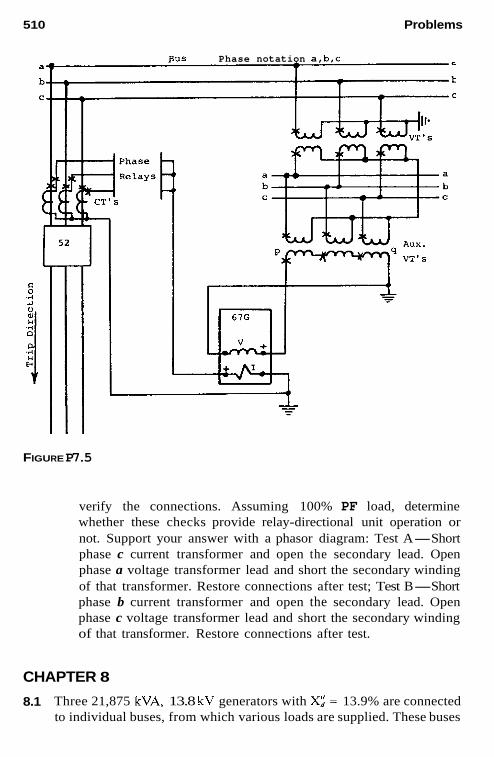
510 Problems
BUS Phase notation a,b.c -
FIGURE P7.5
verify the connections. Assuming 100% PF load, determine whether these checks provide relay-directional unit operation or not. Support your answer with a phasor diagram: Test A-Short phase c current transformer and open the secondary lead. Open phase a voltage transformer lead and short the secondary winding of that transformer. Restore connections after test; Test B-Short phase b current transformer and open the secondary lead. Open phase c voltage transformer lead and short the secondary winding of that transformer. Restore connections after test.
CHAPTER 8
8.1 Three 21,875 kVA, 13.8 kV generators with Xz = 13.9% are connected to individual buses, from which various loads are supplied. These buses


51 2 Problems
FIGURE P8.2
The ground resistor R has a 64.14 kW rating at 138 volts. a.
b.
c.
Determine the fault current magnitude for a single line-to-ground fault between the generator and the power transformer. Determine the three-phase fault current magnitude for a fault be- tween the generator and the power transformer. Choose a CT ratio for the generator differential protection. Com- pare the fault currents of parts a and b with the generator relay pick-up value of 0.15 amp. How much voltage is available to operate an overvoltage relay 59G when connected across the grounding resistor? What is the multiple of pickup if 59G minimum operating value is 5.4 volts.
e. How much current flows through the resistor? Select a CT and suggested overcurrent pickup values for the 50151 relay.
The per unit kVA capability and steady state stability curves at rated terminal voltage for a 50 MVA, 13.2 kV, 60 Hz generator are shown in the diagram in Fig. P8.3. The current transformers used are 30005. For loss-of-excitation protection: a. Translate the steady state stability limit to a per unit R-X diagram
for a terminal voltage of 1.0 per unit. b. Translate the 15 psi capability curve to a per unit R-X diagram for
a terminal voltage of 1.0 per unit. c. With these limits plotted on an R-X diagram, draw a distance relay-
offset mho circle to provide protection for low or loss of excitation on this machine.
d.
8.3

Problems 51 3
FIGURE P8.3
d. For the relay mho circle selected in part c, determine the per unit offset (distance of the circle center from the R-X origin) and the per-unit circle radius. Translate these values to relay ohms for setting a loss-of-excitation relay. R, = 3000:s. R , = 120.
CHAPTER 9
9.1 Assume for this problem that the 69 kV system (Fig. P9.1) is open and make the following calculation: a. Calculate the fault current in the three phases for a solid phase-a-
to-ground fault on the 69 kV terminals. b. Calculate the three phase voltages existing at the fault. c. For this 69 kV ground fault, determine the currents flowing in the
13.8 kV system. d. What are the voltages for the three phases at the 13.8 kV trans-
former terminals for the 69 kV fault? e. Compare the current and voltage phasors on the two sides of the
bank for the 69 kV ground fault. For the transformer bank of Problem 9.1, assume that phases A , B , C on the 13.8 kV side have 30005 C T s with taps at 1500, 2000, 2200,
9.2

514 Problems
13.8kV 69kV
A--a
C
xl= x2 = 12% - 50 MVA
13.8 : 69kV x = 8% - -
FIGURE P9.1
and 2500 amp, and that the 69 kV circuits u, b, c have 6005 multiratio CTs with taps, as indicated in Fig. 5.10. a. Show the three-phase connections for transformer differential re-
lays to protect this bank. b. Select suitable 69 kV and 13.8 kV CTs ratios for this transformer
differential application. c. If the differential relay has taps of 4, 5, 6, and 8, select two taps
to be used with the CT ratios selected in part b so that the percent mismatch is less than 10%. With this application and setting, how much current can flow to operate the differential relay(s) if the phase-a-to-ground fault of Problem 9.1 part a is within the differential zone? How many of the three relays operate for this ground fault?
The transformer hank (Fig. P9.3) shown connected between the 13.8 kV and 2.4 kV buses, consists of three single-phase units, each rated 1000 kVA, 13.8:2.4 - 1.39 kV. a. Connect a two-restraint type differential relay for protection of the
transformer bank. b. Select proper current transformer ratios and relay taps. Assume the
differential relay has ratio adjusting taps of 5 5 to 5:10 with ratios of 1, 1.1, 1.3, 1.5, 1.6, 1.8 and 2.0. The CTs on the 13.8 kV breaker are 2005 with 150, 100, and 50:5 taps, and on the 2.4 kV breaker;
If one of the single-phase transformers is damaged, can service be continued with the remaining two banks? If so, show the connec-
d.
9 3
~oon/i5on/ioon/~oo:~ CTS. c.
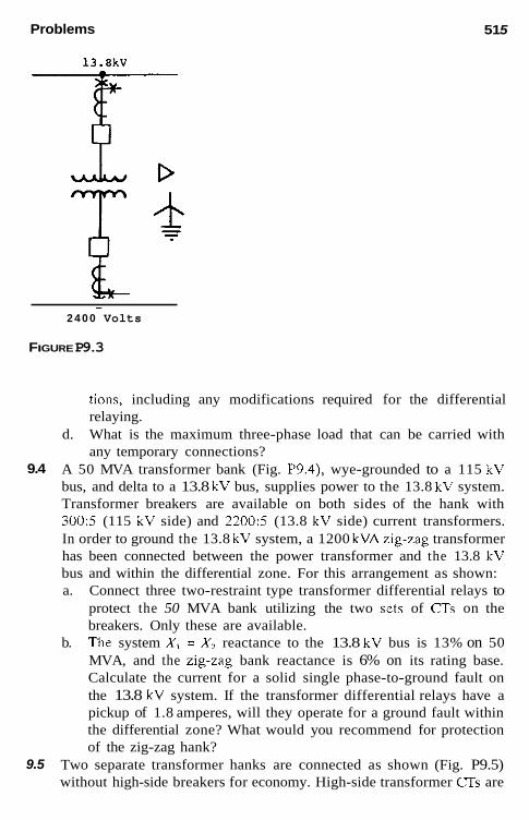
Problems
13.8kV
1 51 5
- 2 4 0 0 Volts
FIGURE P9.3
tions, including any modifications required for the differential relaying.
d. What is the maximum three-phase load that can be carried with any temporary connections?
A 50 MVA transformer bank (Fig. P9.4), wye-grounded to a 115 kV bus, and delta to a 13.8 kV bus, supplies power to the 13.8 kV system. Transformer breakers are available on both sides of the hank with 300:5 (115 kV side) and 2200:5 (13.8 kV side) current transformers. In order to ground the 13.8 kV system, a 1200 kVAzig-zag transformer has been connected between the power transformer and the 13.8 kV bus and within the differential zone. For this arrangement as shown: a. Connect three two-restraint type transformer differential relays to
protect the 50 MVA bank utilizing the two sets of CTs on the breakers. Only these are available. The system X, = X, reactance to the 13.8 kV bus is 13% on 50 MVA, and the zig-zag bank reactance is 6% on its rating base. Calculate the current for a solid single phase-to-ground fault on the 13.8 kV system. If the transformer differential relays have a pickup of 1.8 amperes, will they operate for a ground fault within the differential zone? What would you recommend for protection of the zig-zag hank?
Two separate transformer hanks are connected as shown (Fig. P9.5) without high-side breakers for economy. High-side transformer (JTs are
9.4
b.
9.5

516 Problems
13.8kV
Z i g Zag Transformer 1200 kVA
-
- FIGURE P9.4
not available. The hanks are connected per ANSI Standards. For this arrangement: a. Show complete three-phase connections for protecting these two
transformer banks using three three-winding type transformer dif- ferential relays and the three sets of CTs shown. Discuss the advantages and disadvantages of this protection com- b.
FIGURE P9.5

Problems 517
pared with separate transformer differentials if separate 115 kV transformer C T s had been available.
For the application shown in Fig. 9.12 and 9.13, determine the currents that will flow in the relays for an 800-ampere ground fault. The neutral CT ratio is 2503 and the line CT ratios are 1600:5. In the following determinations, choose a value of “n” to provide a good level of current in the 87 G relay windings: a. b.
9.6
For the ground fault external to the differential protection zone. For the ground fault internal and within the differential protection zone. Assume the low voltage feeders supply zero current to the internal fault.
9.7 A 1 MVA transformer bank, 13.8 kV delta, 480 V wye, solidly grounded with X = 5.75%, supplies a group of induction motors. The source X, = X, is 0.0355 per unit on 5 MVA, 13.8 kV. 13.8 kV, 65 amp fuses are used to protect the transformer bank and the 480 V bus. In order to find the clearing time of the fuses for 480 V arcing faults, determine the following: a. What is the maximum possible ground-fault current at the 480 V
bus? b. With a typical arc voltage of 150 V essentially independent of
current magnitude, determine the magnitude of the arcing fault at the 480 V bus. What is the magnitude of this arcing fault on the 13.8 kV primary? Estimate the total clearing time for the 13.8 kV, 65 amp fuses used in the primary supply to the bank for the 480 V arcing fault. The total clearing time for these fuses is as follows:
c. d.
150 500 175 175 200 115 250 40 300 20 350 9 400 6
CHAPTER 10
10.1 High-impedance voltage-differential relays are to be applied to protect a three-breaker bus, as shown in Fig. 10.9. The CTs are all 600:5

518 Problems
multiratio type with characteristics per Fig. 5.10. For this application, determine the relay-pickup setting voltage and the minimum primary- fault current for which the relays will operate. The maximum external fault is 8000 amp rms. Assume the lead resistance R,. = 0.510 ohms for the maximum resistance from any CT to the junction point.
For the particular relays applied, the pickup setting voltage is:
1, N
V,* = 1.6k(R,, + pR,) - V (10-3)
where 1.6 is a margin factor, k a CT performance factor (assume k = 0.7 for this problem), p = 1 for three-phase faults a n d p = 2 for single- phase-to-ground faults (Fig. 5.9 reference), I, the primary rms exter- nal maximum fault current, and N the CT ratio. K, is the CT resis- tance. p = 2 should be used to determine the value of the V,, setting.
The maximum setting of the relay voltage element should not exceed 0.67 times the secondary exciting voltage of the poorest CT in the differential circuit at 10 amp exciting current.
The minimum internal fault primary current to operate the relays is
I,,,,. = (n l , + I,< + I , ) N primary amperes (10-4)
where n is the number of circuits, I,. the exciting current of the in- dividual CT at the pickup voltage, I, the relay current at the pickup setting voltage, and I,- the current required by a high voltage protec- tive device across the relay coiI (not shown in Fig. 10.9). For this problem, assume I , = 0.2 amp. The relay impedance and generally negligible resistance of the leads from the junction to the relay is 1700 ohms. nI, is applicable in this problem since all three breaker CTs are the same; otherwise this is a summation of the different CT exciting currents at the V, pickup voltage. A feeder circuit is added to the bus of Problem 10.1, making a four- circuit bus. The new breaker has the same type 6005 multiratio CTs. With this addition, the maximum external fault increases to 10,000 amp rms. All other circuit values remain the same. For this change, calculate the relay-pickup setting voltage and the minimum primary- fault current for which the relays will operate.
10.2

Problems 519
CHAPTER 11
11.1 A 2850 hp, 4 kV induction motor is connected to the supply system through a 2.5 MVA transformer, 13.8:4 kV with a reactance of 5.6%. The motor full-load current is 362 amp and its locked rotor current is 1970 amp. The supply system short-circuit MVA at the 13.8 kV terminals of the transformer is 431 maximum, 113 minimum, on 100 MVA base. Determine if a phase instantaneous overcurrent relay can be applied if it is set at half the minimum fault current and twice the locked rotor current. Review the application of Problem 11.1 if a time-delayed instanta- neous unit is applied and set at 1.1 times locked-rotor current. Another feeder is supplied hy the same source as in Prohlem 11.1 through a 2.5 MVA, 13.8:2.4 kV transformer with 5.88% reactance. The largest motor connected to this hank is rated at 1500 hp, 2.3 kV, with a full load current of 330 amp, locked rotor current of 2213.5
11.2
11.3
138kV - MVASC= 10,000
T
10 MVA Lb 7 % -r-4 13.8kV
-
o 500HP
Induction 4160 v.
FUll Load 70 3600 R P M Xd = 17%
o TWO 2OOOHP
a. Motors 4000 volts. FUll Load 250 a. Locked Roto= 1500 a. X" = 24% d
M O t o r S - 6 45HP
8 25HP
25 15HP or less
FIGURE P11.5
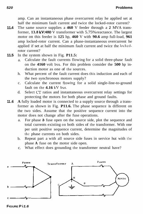
520 Problems
amp. Can an instantaneous phase overcurrent relay he applied set at half the minimum fault current and twice the locked-rotor current? The same source supplies a 460 V feeder through a 2 MVA trans- former, 13.8 kV480 V transformer with 5.75% reactance. The largest motor on this feeder is 125 hp, 460 V with 90.6 amp full-load, 961 amp locked-rotor current. Can a phase-instantaneous overcurrent he applied if set at half the minimum fault current and twice the locked- rotor current? In the system shown in Fig. P11.5: a.
11.4
11.5 Calculate the fault currents flowing for a solid three-phase fault on the 4160 volt bus. For this problem consider the 500 hp in- duction motor as one of the sources.
h. What percent of the fault current does this induction and each of the two synchronous motors supply?
c. Calculate the current fiowing for a solid single-line-to-ground fault on the 4.16 kV bus.
d. Select CT ratios and instantaneous overcurrent relay settings for protecting the motors for both phase and ground faults.
A fully loaded motor is connected to a supply source through a trans- former as shown in Fig. P11.6. The phase sequence is different on the two sides. Assume that the positive sequence current into the motor does not change after the fuse operations. a. For phase b fuse open on the source side, plot the sequence and
total currents existing on both sides of the transformer. With one per unit positive sequence current, determine the magnitudes of the phase currents on both sides. Repeat part a with all source side fuses in service hut with the phase A fuse on the motor side open. What effect does grounding the transformer neutral have?
11.6
b.
c.
FIGURE P i 1.6

Problems 521
CHAPTER 12
12.1 The 12.5 kV distribution feeder (Fig. Pi2.1) has two taps. One is protected by thrce oil circuit reclosers with 701140 amp coils set as in Table P12.1. The other tap is a single phase circuit protected by one 30 amp fuse operating as shown in Table P12.2. The data for the 46 kV fuse is in Table P12.3. The phase and ground relays are very inverse time overcurrent with instantaneous units. Their time-over- current characteristics are shown in lhe typical curves of P12.11. Fault currents are in amperes at 12.5 kV a. Determine the 46 kV fuse time-current characteristic in terms of
12.5 kV amperes for 12.5 kV three-phase, phase-to-phase and phase-to-ground faults. Draw these high side fuse curves along with the recloser and 30 amp fuse curves on time-current iog paper, such as K & E 48 5257, with 12.5 kV amp as the abscissa and time in seconds as the ordinate. Select a suitable ratio for the current transformers to the phase and ground relays. Set and coordinate the phase and ground relays. Provide a min- imum 0.2 scc coordination interval between thc recloser and the relays, and a minimum 0.5 sec between the 46 kV fuse and the relays. Specify tbe time-overcurrent relay tap selected (available
b.
c.
46kV BUÇ
T $ 6 5 amp. Fuse
600:5 Mult i - ra t io CT's To Phase b Ground Relays
30 amp. Fuse Faul t 1 - 3@ Max.= 2300 amp 0G Max.= 2433 amp
Faul t 2 - 30 Max.= 1300 amp 0G Max.= 1110 amp 10
Load
FIGURE P12.1

522 Problems
TABLE P12.1 Circuit Reclosers
Current Time iarnp) isec)
140 20 185 10 200 7.5 275 5 320 4 400 3 480 2 600 1 650 0.8 720 0.7 800 0.6 900 0.5
1200 0.4 1600 0.3 2200 0.25
TABLE P12.2 30-Ampere Fuse
Approximate by a 120" line passing through 1000 arnp at:
0.06 sec for the minimurn rnelt curve 0.1 1 sec for the maxirnurn clearing curve
TABLE P12.3 65-Arnpere Fuse, Minimum Melt
46 kV Time íamp) bec)
130 260 500
1500
300 10
1 0.1

Problems 523
R G H
Values are in secondary ohms
FIGURE P12.5
taps are 1-1.2-1.5-2-2.5-3-3.5-4-5-6-7-8-10), the time dial, and the instantaneous current pick-up for both phase and ground re- lays. Plot the coordination on the curve of part 1.
In the loop system of Fig. 12.4, set and coordinate the phase over- current type relays around the loop in the counterclockwise direction for breakers 4, 6, and 9. Use criteria and the settings for the other relays involved from the example in the text. Apply and set phase instantaneous relays where they are applicable for the breakers 4, 6, and 9 in the system of Fig. 12.4. A 12/16/20 MVA transformer is connected to a 115 kV source through a high side 125E fuse and through a low side recloser to supply a 12.5 kV feeder. The transformer is delta-connected on the high side and solidly wye-grounded on the low side.
The total reactance to the 12.5 kV bus is X, = X, = 0.63 per unit, X,, = 0.60 per unit on 100 MVA. The lines from the 12.5 kV bus have a positive sequence impedance of 0.82 ohm per mile and a zero sequence impedance of 2.51 ohms per mile. Ignore the line angle in this problem.
As a result of a problem it is necessary to operate temporarily with the low side recloser bypassed. Determine how many miles out on the line can be protected by the high side fuse for solid line-to- ground faults. The minimum current to open the fuse is 300 amp. a. Apply and set distance-type relays at Stations H and R for the
protection of line HR in the system in Fig. P12.5. Set zone 1 units for 90% of the protected line, zone 2 to reach 50% into the next line section beyond the protected line, and zone 3 for 120% of the next line section. Plot this system on an R-X diagram with the origin at bus H. Plot the relay settings of part 1 using mho-type characteristics. The mathematical formula for a circle through the origin or relay lo- cation is where Z, is the relay setting at 75":
12.2
123
12.4
12.5
b.

524 Problems
2 = +(Z, - z, A) The first term is the offset from the origin at 75" and the second term the radius. Thus when + is 75", Z = 0, the relay location; when + is 255", Z = Z, the forward reach.
c. What is the maximum load in MVA at 87% P.F. that can be carried over line HR without the distance relays operating? As- sume the voltage transformer ratio R, = 1000 and the current transformer ratio is R. = 80. Apply and set distance relays for line HR as in Problem 12.5 except set the zone 3 unit in the reverse direction to reach 150% of the line section behind the relay. Plot these settings (zone 1 and 2 as in Problem 12.5) and zone 3 as above on the R-X diagram with the origin at bus H. For this application, what is the maximum load in MVA at 87% P.F. that can be carried over line HR without the distance relays operating? R , = 1000 and R, = 80.
The line impedance values for the system in Fig. P12.7 are in percent on a 100 MVA, 161 kV base. The fault values are in MVA at 161 kV for three-phase faults at the buses as indicated. The first value is for maximum conditions, and the second for minimum conditions.
12.6 a.
b.
c.
12.7
Bus S
BUS P Bus L
1-260-195 1- 60- 45 2-140-100 2-110- 70
3-210-160 3- 80- 60 *3,
485-325 430-300
N 2 1 630-570
5 5 8 Bus M 1- 80-50
2-140-90 3- 43-25
FIGURE P12.7
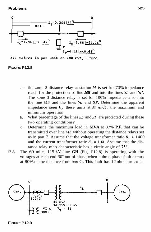
Problems
- T F = 4 . 5 1 L - '
All v a l u e s in per unit on 100 MVA. 11%~.
FIGURE P12.8
525
a.
h.
C.
the zone 2 distance relay at station M is set for 70% impedance reach for the protection of line MS and into the lines SL and SP. The zone 3 distance relay is set for 100% impedance also into the line MS and the lines SL and SP. Determine the apparent impedance seen by these units at M under the maximum and minimum operation. What percentage of the lines SL and SP are protected during these two operating conditions? Determine the maximum load in MVA at 87% P.F. that can he transmitted over line MS without operating the distance relays set as in part 2. Assume that the voltage transformer ratio R , = 1400 and the current transformer ratic R, = 100. Assume that the dis- tance relay mho characteristic has a circle angle of IS".
12.8. The 60 mile, 115 kV line GH (Fig. P12.8) is operating with the voltages at each end 30" out of phase when a three-phase fault occurs at 80% of the distance from bus G. This fault has 12 ohms arc resis-
FIGURE P12.9

526
1-2247-2708 2-1150-1334 I
3- 673- 1 6 0 -
Problerns
+ t i 1 - 7 6 6 - 3 1 5
12kY 4th - x (31
tance. The currents flowing to the fault are as shown and are in per unit at 100 MVA, 115 kV. a. Determine the apparent impedance seen by the distance relays at
G for this fault. b. Determine if the zone 1 mho unit at G set for 90% of the line
C H can operate on this fault. Assume the angle of the mho char- acteristic (Fig. 6.12b) is 75". Determine the apparent impedance seen by the distance relays at H for this fault. Determine if the zone 1 mho unit at H set for 90% of the line GH can operate for this fault. Assume the angle of the mho char- acteristic is 75".
e. Describe how this three-phase fault can be cleared by the line distance relays.
The 40 MVA transformer bank (Fig. P12.9) has tap changing under load (TCUL) with low voltage 1 1 0 % taps. The reactances at the high, mid, and low voltage taps are 7.6% at 38 kV, 8% at 34.5 kV and 8.5% at 31 kV respectively. This bank is connected directly to a 115 kV transmission line without a high side breaker. There are no 115 kV voltage or current transformers avaiiable at G. In order to provide phase distancc line protection, the relays must be set to iook through
c.
d.
12.9.
Volts at BUS G
1--4% 23.206 2- 8.210 11.428 3- 4 , 8 0 6 1,375
"2 3"o
CT'S "T'5 d- 500:s 1,- 600:l
500;s i - 1200:1 f- 200:5
V o l t s at BU5 H
"2 3"o ~~
1- 7,392 2.115 2- 9,684 3,912 3-31.022 52,888
<Io YsIUe.,
FIGURE P12. l la

Problems 527
FIGURE P12.11 b
the transformer into the line. Assume that any phase shift through the transformer does not change the relay reach by either the connections or relay design. a. Set zone 1 phase distance relays at G for a 12 mile line GH
where Z,. = 10 /80" ohms. Note that it is necessary to determine which transformer bank tap gives the lowst value of ohms to bus

Problems
H as viewed from bus G to prevent the relays from overreaching bus H as taps are changed. Set zone 1 for 99%Xr + 90%Z,..
b. With this setting of part 1, what percent of the line is protected by zone l ?
c. What percent of the line will be protected when the other taps are in service with the setting of part l ?
d. In view of the preceding analysis, what recommendations would you make for line protection?
Repeat Problem 12.9 but with a 50 mile, 115 kV line where Z,, = 40 & ohms. Compare the protection for the 12 mile line of Problem 12.9 with the protection for the 50 mile line. Ground directional overcurrent relays are to be applied to the 69 kV and 138 kV breakers for the protection of the 138 kV line that in- cludes the autotransformer as shown in Fig. P12.11. To determine the best method of directional sensing fault I , = I2 and I. currents and V2 and V, voltages are indicated for the three different line-to-ground faults. a. Determine the secondary (relay) quantities that could be used to
polarize and operate ground relays at both the G and H terminals. b. Make recommendations for the preferred method to polarize and
operate the ground relays at G and H .
12.10.
12.11.
CHAPTER 14
14.1. For the system of Problem P12.5: a. Draw the locus of the surge ohms seen by the relays at H and R
as the generators at the two ends of the system slip a pole. As- sume that the two generator voltages remain equal in magnitude throughout the swing. Locate the 604 90", 120", 180", 240", 270", and 300" points. What is the magnitude of impedance as seen from bus H and from bus R for a 120" swing? With the distance settings applied in Problem 12.5, determine which distance relays will operate on the swing and at what swing angle this will occur. Repeat part c but with the distance settings as applied in Problem 12.6.
b.
c.
d.

Index
Air-core transformer differential
ANWIEEE standardized function
equipment, 12-16 Audiotape:
protection for buses, 351-352
numbers for relays and
for phase comparison pilot system,
for pilot system protection, 467 Automatic circuit reclosers, 388 Automatic line reclosers, 490-491 Automatic synchronizing, 495 Auxiliary C T s in CT secondary
circuits, 157-158 Auxiliary relays, 26 Auxiliary sewice system for generator
Available fault indicators, 24-25
Backup protection, 167-168
459-462
protection, 272-273
for breaker failure, 437-442 for generator and connected
system, 247-249
[Backup protection] negative-sequence c w ~ r n t backup
Balanced three-phase power system, protection, 249
circuit and phase diagrams for, 53-55
Base quantities, 39-40 Breaker-and-a-half bus, 343 -344
Bus protection, 335-356 advantages and disadvantages of, 347
breaker-and-a-half bus, 343-344,
differential protection, 345-352 double breaker-double bus, 341-
ground-fault bus, 356 main and transfer buses with single
breaker, 338, 346 ring bus, 342, 347 single breaker-double bus, 338-
341, 346 single breaker-single bus, 337-338,
36
347
342, 346
529

530 Index
[Bus protection] single bus-connected with bus tie,
336 ~~. transformer-bus combination, 344-
345, 341 typical bus arrangements, 335-337
advantages and disadvantages, 346-347
Bus transfer and reclosing, 379
Capacitors, 332-333 shunt capacitor applications, 332 shunt capacitor protection, 332-
333 Circuit breakers, 9-12
backup protection for breaker
connections, 16-19 failure, 437-442
Classification of relays, 25-26 Communication channels for pilot
protection, 465-468 Coordinating time interval (CTI), 389 Coupling capacitor voltage
transformers (CCVTs), 129, 134
for protcction applications, 158- 159
Current fault phasors, 114-111 Current polarization, ground fault
directional sensing with, 61- 69
Current transformers (CTs), 16, 129, 130, 131
auxiliary C T s in CT secondary circuits. 157-158
equivalent circuit of VTs and, 132- 133
flux summation, 150-151 paralleling f f s in differential
circuits, 291-293 performance evaluation, 153- 156
performance on DC components,
performances on symmetrical AC
for phase faults, 141-147
151 - 153
components, 135-141
[Current transformers] for protection applications, 134-
135 residual flux and subsidence
transients, 156-157 secondary burdens during faults,
141 unenergized, effect on performance,
149-150
233 Customer owned generator (Co-Gen),
Dead-tank circuit breakers, 10-1 I Delta-connected generators, ground-
fault prokction for, 25-252 Delta-connected impedances, 38 Differerential relay protection, 161-165
for buses, 345-352 for motors, 364-366 for transformers, 277, 281 -282
special connections for, 293-295 Direct-connected generators, 242-243
Directional comparison blocking pilot
Directional comparison overreaching
protection for, 234-235
system, 446-449
transfer trip pilot system, 452- 454
Directional comparison unblocking pilot system, 449-452
Directional comparison underreaching transfer trip pilot system, 454- 455
protection with, 302-307 Directional relays, ground differcntial
Directional-sensing power relays, 174 Directional wave comparison systems,
Disconnecting devices, location of, 24 Dispersed storage and generation
464
(DSG), 233 protection for, 400-401
applications for tapped and Distance relays:
multiterminal lines, 413-416
Index 531
[Distance relays] out-of-step detection by, 488-490 protection for ground faults, 417-
protection for phase faults, 410-
voltage sources for, 416
coordination for, 396-399 reclosing, 491-492
341-342
419
413
Distribution feeder:
Double breaker-double bus protection,
advantages and disadvantages, 346 Double-phase-to-ground faults, 90-92 Dual polarization for ground relaying,
427
Economics of protective relay systems, 22-23
Effective grounding, 217-220 Electric power and power
transmission. 476-477
Fault impedance, 87-88 Fadl resistance, relaying and, 419-
Feeder protection. See Line protection Ferroresonance in three-phase power
Fiber-optic channels, 459-462 Field ground protection for a
Flux summation CTs, 150-151 Frequency relaying:
for industrial systems, 497 for load-shedding-load saving,
421
systems, 220-226
generator, 260-261
495-497 Fuses, 388
Generators, 231-274 field ground protection, 260-261 generator connections and typical
protection, 234-237 generator off-line protection, 261 generator-tripping systems, 272
[Generators] multiple generator units connected
directly lo a transformer, 260 negative-sequence current backup
protection, 249 phase fault backup protection, 247-
249 potential problems, 231-234 reduced or loss excitation
protection, 261 -266 station auxiliary service system,
272-273 stator ground-fault protection, 249-
259 stator phase-fault protection, 237-
246 synchronous condenser protection,
271 -272 for system disturbances and
operational hazards, 266-271 unit transformer phase-fault
differential protection, 246- 247
ungrounded systems, 196- 200
protectinn for transformcrs, 296-298
Ground-detection methods for
Ground (zero-sequence) differential
Ground distance d a y s , 186-187 Ground-fault bus, 356 Ground-fault directional sensing:
with current polarization, 67-69 with voltage polarization, 65-67
Ground fault protection: for lines, 417 for motors, 366-367
Grounding of power systems. See System grounding principles
Grounding transfonncr protection, 300-301
Ground relays, 186-187 dual polarization for, 417 mutual coupling and, 428-435 performance evaluation for, 148-
149

532 Index
Hazardous-type applications,
High-impedance-grounding systems,
High-impedance voltage differential
grounding for, 212-214
200-212
protection: for buses, 349-351 for generators, 240-241
High-resistance grounding, 202-203 general recommendations for, 228
High voltages, ferroresonance at, 223-226
Independent power producer (IPP) units, 233, 234
Individual transformer units,
Induction motor equivalent circuit,
Industrial generators, 232-233 Industrial power producers, over- or
protection for, 269-270, 400-401
protection for, 324-325
360-362
underfrequency protection for, 269-270
Input devicces, location of, 24 Input sources for relays, 129-160
auxiliary current transformer in C T secondary circuits, 157-158
CT performance evaluation, 153- 156
on DC components, 151-153 for phase faults, 141-147 for protection applications, 134-
on symmetrical AC components, 135
135-141 (JT residual flux and subsidence
transients, 156-157 effect of unenergized CTs on
performance, 149-150 equivalent circuits of current and
voltage transformers, 132-133 flux summation current transformer,
150-151 performance evaluation for ground
relays, 148-149
[Input sources for relays] secondary burdens during faults,
voltage transformers for protection 141
applications, 158-159 Instantaneous current-voltage relays,
172- 174 Institute of Electrical and Electronic
Engineers (IEEE), definition of a relay, 1
logging (extreme load variations) protection for motors, 379 380
Line protection, 383-443 automatic linc reclosing, 490-491 backup for breaker failure, 437-
classification of lines and feeders,
coordinating fundamentals and
442
383-386
general setting criteria, 389- 392
fceder, 396-399
401-407
overcurrent relays, 421 -423
faults, 417-418
410-413
tapped and multiterminal lines, 413-416
protection and coordination, 393-396
relaying, 427
421
negative sequence, 427-428
coordination for a distribution
coordination for a loop systcm,
directional sensing for ground-
distance protection for ground
distance protection for phase faults,
distance relay applications for
distribution feeder, radial line
dual polarization for ground
fault resistance and relaying, 419-
ground directional sensing with
Index 533
[Line protection] ground distance relaying with
mutual induction, 435-436 ground-fault protection for lines, 417 independent power producer and
DSGs connected to distribution lines, 400-401
instantaneous trip applications for a loop system, 407-408
long EHV series-compensated line protection, 436-437
mutual coupling and ground relaying, 428-435
network and spot network systems, 409-410
reclosing on lines with transformers and reactors, 494
remote versus local backup, 437- 442
short-line applications, 408-409 techniques for, 387-388
automatic circuit reclosers, 388 coordinating time interval, 389 fuses, 388 sectionalizers, 389
voltage polarization limitations, 427 voltage sources for distance relays,
416
for, 495-497 Load shedding, frequency relaying
Load tap-changing transformers, 287 Local backup-breaker failure, 439-
Locked-rotor protection for motors. 441
368-369 for large motors, 370-371
Long EHV series-compensated line protection, 436-437
Last excitation protection for a generator, 261-266
Low-impedance grounding, 214-217 general recommendations for, 228
Magnetizing inrush Current phenomenon, 278-280
Main and transfer buses with single
advantages and disadvantages, breaker, 338
346 Mechanical fault detection for
transformers, 299-300 Mining systems, grounding for, 212-
Moderate high-impedance differential
Monitoring relays, 25-26 Motors, 357-381
214
protection for buses, 352
bus transfer and reclosing, 379 dirferential protection, 364-365 general protection, 362 ground-fault protection, 366-367 induction motor equivalent circuit,
locked-rotor protection for large
motor characteristsics involved in
multifunction microprocessor motor
phase-fault protection, 362-364 potential motor hazards, 357-358 repetitive starts and jogging
protection, 379-380 synchronous motor protection,
system unbalance and motors, 371 -
thermal and locked-rotor protection,
unbalance and phase rotation
undervoltage protection, 378
360-362
motors, 370-371
protection, 359-360
protection units, 380
380-381
377
368-369
protection, 378
Multi-CT differenlial protection for all sizc generators, 238-240
Multifunction microprocessor motor protection units, 380
Multirestraint current differential protecion for buses, 346-349
Mutual coupling, ground relaying and, 428-435

534 Index
Negative-sequence current backup
Negative-sequence network, 81 -83 Network system:
protection, 249
protection for, 409-410 See also Sequence networks
Nonutility generation (NUG), 233
Off-frequency operation for large
protection for, 269 Off-line protection for a generator,
261 Oil-immersed reactors, 328 Operational hazards, generator
protection for, 266-271 inadvertent energization, 267-268 loss of prime-mover, 266-267 loss of synchronism, 270 off-frequency operation for large
over- or underfrequency, 269-270 overload, 268-269 overvoltage, 267 suhsynchronous oscillations, 271 unbalanced currents, 268 undervoltage or overvoltage, 270
steam turbines, generator
steam turbines, 269
Out-of-step detection by distance
Overcurrent-distance protection, 165 -
for transformers, 308-310, 316-323
for transformers, 324 transient, 195, 196
relays, 488-490
167
Overvoltage:
Paralleling C T s in differential circuits, 291-293
Parallel transformer units, protection for, 325-327
Percent, 36 advantages of, 36-37
Percent impedance, 40-41 changing quantities to different
bases, 44-46 of transformer units, 41-43
Personality factor influencing protective relaying, 24
Per unit value, 36 advantages of, 36-37
Per unit impedance, 40-41 changing quantities to different
bases, 44-46 of transformer units, 41-43
Phase distance relays, 175-177 backup protection for generator and
connected system, 248-249 Phase-fault protection for motors,
362-364 Phase rotation, 55-56 Phase-to-phase faults, 89-90 Phasors, 47-56
circuit and phasor diagram for balanced three-phase power system, 53-55
combining phasors, 50 definition of, 47-48 diagram for, 53 nomenclature for cunent and
voltagc, 51-53 phasor diagram for sinusoidal
quantities, 49-50 phasor diagram requiring a circuit
diagram, 51 phase rotation and, 55-56 representation, 48-49 voltage and current phasors for
shunt faults, 107- I10 Pilot relaying, 444-475
audiotone or fiber-optic channels, 459-462
ch:i:inels for protective relaying, 446
communication channels for protection, 465-468
directional comparison blocking pilot system, 446-449
dircctional comparison overreaching transfer trip pilot system, 452-454
pilot system, 449-452 directional comparison unblocking

Index 535
[Pilot relaying] dircctional comparison
underreaching transfer trip pilot system, 454-455
system, 464 directional wave comparison
general evaluation, 468-469 pilot wire relaying-wire line
channels, 455-459 protection of wire-line pilot
circuits, 470-475 segregated phase comparison pilot
systems, 462 single-pole-selective-pole pilot
systems, 463-464 transfer trip system, 464-465
directional sensing for ground
cunenl polarization, 67-69 other directional-sensing
voltage polarization, 65-67
Polarity, 56-69
faults
connections, 68
for phase-fault directional sensing,
relay polarity, 59-61 transformer polarity, 56-59
Polar unit, 174-175 Polyphase MHO units, 181-185 Positive-sequence network, 79-81 Power-line carrier for pilot protection,
Power transmission, electric power
Principles of relay application, 28-30 Protection fundamentals, 161-189
backup prolectioo, 167-168 basic design principles, 168- 187
61-65
465-467
and, 476-477
directional-sensing power relays, 174
instantaneous current-voltage relays, 172-174
the mho characteristic, 177-180 other mho units, 185 phase distance relays, 175-177
[Protection fundamentals] polar unit, 174-175 polyphase mho units, 181-185 reactance units, 185-186 the R-X diagram, 177, 178 single-phase mho units, 180-181 time-overcunent relays, 169-171
differenbal principles, 161-165 ground distance relays, 186-187 overcurrent-distance protection and
basic proteclion problems, 165-167
187-188
28-30
solid-state microprocessor relays,
Protection zones of the power system,
Protective relay, 1-2, 5-9, 25 basic objectives of, 19-23 circuit breakers and, 9-12 connections, 16- 19 information required for, 30-32 major factors affecting, 23-25 performance of, 26-28
Reactance unit, 185-186 Reactors, 327-332
general application of shunt reactors, 329-331
protection for, 331-332 reclosing on lines with, 494 types of, 327-328
Reclosing rebdys, 25, 388 Reduced or lost excitation protection
Regulating relays, 25 Regulating transformers, 307 Relay polarity, 59-61 Reliability of protective relay systems,
19-21 Remore backup, 438-439 Resonant grounding, 200-202 Ring bus, 342
R-X diagram, characteristics of
for a generator, 261-266
advantages and disadvantages, 347
distance relays on, 177, 178

536 Index
Safety grounding, 226-227 Sectionalizers, 388 Segregated phase comparison pilot
system, 462 Selectivity of protective relay
systems, 21 Sequence networks, 79-87
reduction of, 85-87 Short circuit, causes of, 2-4 Shunt capacitors:
applications of, 332 protection for, 332-333
system voltage profiles during,
voltage and current phasors for,
Shunt faults:
110-113
107-110 Shunt reactors, 327-328
applications of, 329-331 protection for, 331-332
double-phase-to-ground faults, 90-
fault impedance, 87-88 phase-to-phase faults, 89-90 single-phase-to-ground faults, 89 substation and tower-footing
impedance, 88 three-phase faults, 88, 89
Simultancous unbalances, 106 Single breaker-bus type, 337-338
advantages and disadvantages, 346 Single breaker-double bus type, 338-
Shunt unbalances, 87-93
92
341
346 advantages and disadvantages,
Single-phase MHO units, 180-181 Single-phase-to-ground faults, 89 Single-pole-selective-pole pilot
systems, 463-464 Small kVA (MVA) generators,
differential protection for, 237-238
Solid (effective) grounding, 217-220 general recommendations for, 228
Solid-state microprocessor relays, 7,
Speed of protective relay systems,
Spot network systems, protection for,
Stability:
187-188
21-22
409-410
out-of-step detection by distance
steady-state operation and, 477-
system swings and protection, 482-
transient operation and, 479-481 Station auxiliary selvice system, 272-
273 Stator ground-fault protection in a
generator, 249-259 Stator-phase fault protection for all
size generators, 237-246 Steam turbines, off-frequency
operation, generator protection for, 269
relays and, 488-490
478
488
Substation impedance, 88 Subtransmission-line reclosing, 492-
Symmetrical components, 70- 128 494
general equations, 73-74 negative-sequence set, 72-73, 74 positive-sequence set, 71-72 positive-sequence sourccs, 76-79 sequence independence, 74-76 sequence networks, 79-87 series and simultaneous unbalances,
106 shunt unbalance sequence network
interconnections, 87-93 zero-sequence set, 73, 74
Synchronism check relays, 25 Synchronizing relays, 25 Synchronous condenser protection,
271-272 Synchronous motor protection, 380-
System configuration, 30 381

Index 537
System disturbances, generator protection for, 266-271
inadvertent energization, 267-268 loss of prime-mover, 266-267 loss of synchronism, 270 off-frequency operation for large
over- or underfrequency, 269-270 overload, 268-269 overvoltage, 267 subsynchronous oscillations, 271 unbalanced currents, 268 undervoltage or overvoltage, 270
System faults, 4 System grounding principles, 190-
230 ferroresonance in three-phase
power systems, 220-226 ground-detection method for
ungrounded systems, 196-200 high-impedance-grounding systems,
200-212 low-impedance grounding, 214-
217 for mining or other hazardous type
applications, 212-214 recommendations for, 227-229 safety grounding, 226-227 solid (effective) grounding, 217-
transient overvoltages, 195, 196 ungrounded systems, 190-195
steam turbines, 269
220
Thermal protection: for motors, 368-369 for transformers, 324
Three-phase faults, 88 Three-phase power systems:
balanced, phasor diagrams for, 53-
ferroresonance in, 220-226 Time-overcurrent relays, 169-171 Tower-footing impedance, 88 Transfer bus with single breaker, 338
advantages and disadvantages, 346
55
Transfer trip systems, 298-299, 464-
Transformer polarity, 56-59 Transformers, 16, 275-327
465
application and connection of transformer differential relays, 281 -282
balancing, 291
345
347 differential protection for three-
phase hanks of single-phase transformer units, 295-296
280- 28 1
298-299
protection, 277
directional relays, 302-307
300-301
application of auxiliaries for current
-bus combination protection, 344-
advantages and disadvantages,
differential relay characteristics of,
equipment for trip systems for,
factors affecting differential
ground differential protection with
grounding transformer protection,
load tap-changing transformers, 287 magnetizing inrush, 278-280 mechanical fault detection for,
overcurrent protection for, 308-
overvoltage and, 324 paralleling cli in differential
per unit and percent impedance of,
polarity of, 56-59 protection of regulating
transformers, 307 reclosing on lines with, 494 special connections for transformer
thermal protection for, 324 transformer overload-through-fault
withstand standards, 310-315
299-300
310, 316-323
circuits, 291 -293
41-43
differential relays, 293-295

538 Index
[Transformers] typical protection for, 324-327 unit transformer phase-fault
differential protection, 246- 247
(CTs); Voltage transformers See also Current transformers
( W S ) Transient overvoltages, 195, 196 Transmission-line reclosing, 492-
494 Tripping systems for generator
protection, 272
Undervoltage protection for motors,
Unenergized CTs effect on
Ungrounded systems, 190- 195
378
performance, 149-150
general recommendations for, 228 ground-detection methods for, 196-
ground-fault protection for 200
ungrounded generators, 252- 253
Unit-connected generators, protection for, 235-237
Unil transformer phase-fault differential protection, 246- 247
Utility generators, 232
for, 269 over- or underfrequency protection
Voltage fault phasors, 114-117 Voltage polarization, ground-fault
directional sensing with, 65- 67
Voltage sources for distance relays, 416
Voltage lransformers (VTs), 16, 129, 132, 133
cquivalent circuits of CTs and,
for protective applications, 158- 132-133
159
Wire-line pilot circuits, protection for,
Wye-connected generators, ground-
Wye-connected impedance, 38
Zero-sequence differential protection
Zero-sequence network, 83-85
470-475
fault protection for, 250-251
for transformers, 296-298

Preface to the First Edition
Protective relaying is a vital part of any electric power system: quite un- necessary during normal operation, but very important during trouble, faults, and abnormal disturbances. Properly applied protective relaying initiates the disconnection of the trouble area while operation and service in the rest of the system continue.
This book presents the fundamentals and basic technology of appli- cation of protective relays in electric power systems and documents the protection practices in wmmon use. The objective is to provide a useful reference for practicing engineers and technicians as well as a practical book for college-level courses in the power field. Applications with examples are included for both utility and industrial-commercial systems operating gen- erally above 480 volts.
Protective relay designs vary with different manufacturers and are wn- stantly changing, especially as solid state technology impacts this area. How- ever, protective relaying applications remain basically the same: relatively independent of design and their trends. As a result, design aspects are not emphasized in this book. This area is best covered by individual manufac- turer's information.
Protective relaying can be considered a vertical specialty with a hori- zontal vantage point; thus, while specialized, it is involved with and requires knowledge of all of the equipment required in the generation, transmission,
ix

about the first edition . . “...demonstrates succinctly how to safeguard electric systems.”
-Electrical Review
about the second edition . . . Presenting the fundamental theories and applications of relays used for the protection of electric power systems, this eagerly anticipated Second Edition of a widely used resource has been fully revised and updated to reflect the latest developments in the field.
Maintaining the features that sent the previous edition into 10 printings, Protective Relaying, Second Edition covers large and small utility systems as well as industrial and commercial systems. ..provides a completely new treatment of generator protec- tion in compliance with the most recent governmental rules and regulations.. . supplies expanded information on symmetrical components.. .delineates individual protec- tion practices for all equipment components.. .furnishes an overview of power system grounding, including system ferroresonance and safety grounding basics.. . analyzes power system performance during abnormal conditions.. .describes the relationship of input source performance to protection.. .and more.
about the author. . . J. LEWIS BLACKBURN was an independent consultant located in Bothell, Washington, until his recent death. Mr. Blackburn worked on the engineering staff of the West- inghouse Electric Corporation, Relay-Instrument Division in Newark, New Jersey, from 1936 through 1978. From 1948 on, he taught professional seminars and uni- versity courses on relaying, symmetrical components, and power transmission. The author of Symmetrical Components for Powei- Systems Engineering (Marcel Dekker, Inc.), Mr. Blackhum received the International Conference on Large High Voltage Electrical Systems (CIGRE) U.S. National Committee Attwood Associate Award (1986). the Institute of Electrical and Electronics Engineers (IEEE) Centennial Medal (1984). the IEEE Educational Activities Board Outstanding Service Award (1979), the IEEE Power System Relaying Committee Distinguished Service Award (1978), and the Westinghouse Order of Merit (1971). He was made a Fellow of the IEEE in 1970 and a Life Fellow in 1978. In 1980 the “J. Lewis Blackbum Room” was dedicated at the Westinghouse Auditorium in Coral Springs, Florida. Mr. Blackburn was a member of the IEEE Power Engineering, Industrial Applications, and Professional Communications Societies. He was also a member of CIGRE and Advisor to the U.S. Representative on Study Committee 34 (Protection). Mr. Blackburn received the B.S. degree (1935) in electrical engineering from the University of Illinois, Urbana.
Printed in the United States of America IS6 N: 0-8247-99 18-6
MARCEL DEKKER, INC. NEW YORK - BASEL HONC KONC

Protective Relaying

POWER ENGINEERING
Series Editor
H. Lee Witlis
ABB Power T&D Company Ins. Cory. North Ouolina
1. Power Distribution Planning Reference Book, H. Lee Willis 2 . Transmission Network Protection: Theory and Practice, Y. G.
Paithankar 3. Electrical Insulation in Power Systems, N. H. Malik, A. A. Al-Arainy,
and M. 1. Qureshi 4. Electrical Power Equipment Maintenance and Testing, Paul Gill 5. Protective Relaying: Principles and Applications, Second Edition, J.
Lewis Blackburn
ADDITIONAL VOLUMES IN PREPARATION

Library of Congress Cataloging-in-Publication Data
Blackbum, J. Lewis. Protective relaying : principles and applications / J. Lewis Blackbum. - 2nd
edition. p. cm. - (Power engineering ; 5 )
Includes index. ISBN 0-8247-9918-6 (acid-free paper) I . Protective relays. I. Title. 11. Series.
TK2861.BS9 1997 621.31’7-dc21
97-33 I10 CIP
The publisher offers discounts on this book when ordered in bulk quantities. For more information, write to Special Sales/Professional Marketing at the address below.
This book is printed on acid-free paper
Copyright 0 1998 by MARCEL DEKKER, INC. All Rights Reserved.
Neither this book nor any pan may be reproduced or transmitted in any form or by any means, electronic or mechanical, including photocopying, microfilming, and recording, or by any information storage and retrieval system, without permission in writing from the publisher.
MARCEL DEKKER, INC. 270 Madison Avenue, New York, New York 10016 http:/hvww.dekker. corn
Current printing (last digit): 10 9 8 7 6 5 4 3 2 1
PRINTED I N THE UNITED STATES OF AMERICA

To my wife PEGGY
Series Introduction
Power engineering is the oldest and most traditional of the various areas within electrical engineering, yet no other facet of modern technology is currently undergoing a more dramatic revolution in both technology and industry structure. This second book in Marcel Dekker, Inc.’s Power Engi- neering series covers one of the cornerstones of modern power systems, the protective relay engineering necessary to ensure secure operation of the in- terconnected power system. Without a doubt, as the electric power industry moves toward a fully open, deregulated framework, protective relaying will remain as critical to satisfactory operation as ever, hut become even more challenging, as a multitude of power producers compete to obtain long- distance wheeling from a common transmission grid.
J. Lewis Blackburn’s original Protective Relaying: Principles and Ap- plications has long been regarded as an essential reference on protection engineering of modem power systems. This second edition provides a wealth of additional and revised material throughout, all of it in the same very thorough, practical style as the original. In particular, the additions regarding generation protection, system disturbances, and interconnected operational hazards will be invaluable given the concern many power engineers have about operating a transmission grid in an open access environment.
As the editor of the Power Engineering series, I am proud to include Protective Relaying: Principles and Applications among this important
V
vi Series Introduction
group of books. Like all the volumes planned for the series, Lewis Black- bum’s book provides modem power technology in a context of proven, practical application, useful as a reference book as well as for self-study and advanced classroom use. This series will eventually include books covering the entire field of power engineering, in all of its specialties and subgenres, all aimed at providing practicing power engineers with the knowledge and techniques they need to meet the electric industry’s challenges in the 21st century.
H. Lee Willis

Preface to the Second Edition
This new edition of Protective Relaying has been written to update and expand the treatment of many important topics in the first edition, which was published in 1987. The structure is similar to that of the first edition, but each chapter has been carefully reviewed and changes have been made throughout to clarify material, present advances in relaying for the protection of power systems, and add additional examples. The chapter on generator protection has been completely rewritten to reflect current governmental rules and regulations. Many figures are now displayed in a more compact form that makes them easier to refer to. As in the first edition, additional problems are provided at the back of the book for further study. I have tried again to present the material in a straightforward style, focusing on what will he most useful to the reader. I hope that this volume will be as well received as the first edition was.
J. Lewis Blackburn
vii

X Preface to the First Edition
distribution, and utilization of electrical power. In addition, it requires an understanding of how the system performs normally as well as during faults and abnormal conditions. As a result, this subject provides an excellent back- ground for specialized study in any of the individual areas and is especially important for system planning, operation, and management.
Fifty years of friends, associates, and students within Westinghouse, the IEEE, CIGRE, many utilities, and industrial companies around the world have directly or indirectly contributed to this book. Their contributions and support are gratefully acknowledged.
Special acknowledgement and thanks are extended to Rich Duncan for his enthusiastic encouragement and support during the preparation of this manuscript, and to W. A. Elmore, T. D. Eetes, C. H. Griffin, R. E. Hart, C. J. Heffeman, and H. J. Li for photographic and additional technical help.
And my gratitude to Dr. Eileen Gardiner of Marcel Defier, Inc., who most patiently encouraged and supported this effort.
J. Lewis Blackburn

Contents
Series Infroduction Preface fo the Second Edifion Preface to the Firsf Edition
1 Introduction and General Philosophies
1.1 Introduction and Definitions 1.2 1.3 Typical Power Circuit Breakers 1.4 Nomenclature and Device Numbers 1.5 1.6 1.7 1.8 Classification of Relays 1.9 Protective Relay Performance 1.10 Principles of Relay Application 1.11 Information for Application Bibliography
Fundamental Units: Per Unit and Percent Values
2.1 Introduction 2.2
Typical Protective Relays and Relay Systems
Typical Relay and Circuit Breaker Connections Basic Objectives of System Protection Factors Affecting the Protection System
2
Per Unit and Percent Definitions
V vii ir
1
1 5 9
12 16 19 23 25 26 28 30 32
35
35 36
xi

xii Contents
2.3 2.4 2.5 Base Quantities 2.6 2.7 2.8
Bibliography
Advantages of Per Unit and Percent General Relations Between Circuit Quantities
Per Unit and Percent Impedance Relations Per Unit and Percent Impedances of Transformer Units Changing Per Unit (Percent) Quantities to Different Bases
3 Phasors and Polarity
3.1 Introduction 3.2 Phasors 3.3 Circuit and Phasor Diagrams for a Balanced
Three-Phase Power System 3.4 Phasor and Phase Rotation 3.5 Polarity 3.6 Application of Polarity for Phase-Fault Directional
Sensing 3.7 Directional Sensing for Ground Faults: Voltage
Polarization . 3.8 Directional Sensing for Ground Faults: Current
Polarization 3.9 Other Directional-Sensing Connections 3.10 Summary
4 Symmetrical Components: A Review
4.1 Introduction and Background 4.2 Positive-Sequence Set 4.3 Nomenclature Convenience 4.4 Negative-Sequence Set 4.5 Zero-Sequence Set 4.6 General Equations 4.7 Sequence Independence 4.8 Positive-Sequence Sources 4.9 Sequence Networks 4.10 Shunt Unbalance Sequence Network Interconnections 4.11 Example: Fault Calculations on a Typical System
Shown in Figure 4.16 4.12 Example: Fault Calculation for Autotransformers 4.13 Example: Open-Phase Conductor 4.14 Example: Open Phase Falling to Ground on One Side
36 37 39 40 41
44 46
47
47 47
53 55 56
61
65
67 69 69
70
70 71 72 72 73 73 74 76 79 87
93 98
102 104

Contents xiii
4.15 Series and Simultaneous Unbalances 4.16 Overview 4.17 Summary Bibliography Appendix 4.1
Appendix 4.2
Appendix 4.3
Short-circuit MVA and Equivalent Impedance Impedance and Sequence Connections for Transformer Banks Sequence Phase Shifts Through Wye-Delta Transformer Banks
5 Relay Input Sources
5.1 Introduction 5.2 Equivalent Circuits of Current and Voltage
Transformers 5.3 Current Transformers for Protection Applications 5.4 Current Transformer Performance on a Symmetrical
Ac Component 5.5 Secondary Burdens During Faults 5.6 CT Selection and Performance Evaluation for Phase
Faults 5.7 Performance Evaluation for Ground Relays 5.8 Effect of Unenergized CTs on Performance 5.9 Flux Summation Current Transformer 5.10 Current Transformer Performance on the Dc
Component 5.11 Summary: Current Transformer Performance
Evaluation 5.12 Current Transformer Residual Flux and Subsidence
Transients 5.13 Auxiliary Current Transformers in CT Secondary
Circuits 5.14 Voltage Transformers for Protective Applications Bibliography
Protection Fundamentals and Basic Design Principles
6.1 Introduction 6.2 The Differential Principle 6.3 Overcurrent-Distance Protection and the Basic
Protection Problem 6.4 Backup Protection: Remote Versus Local 6.5 Basic Design Principles
6
106 107 117 117
118
119
126
129
129
132 134
135 141
141 148 149 150
151
153
156
157 158 160
161
161 161
165 167 168

xiv Contents
6.6 Ground Distance Relays 6.7 Solid-state Microprocessor Relays 6.8 Summary Bibliography
7 System-Grounding Principles
7.1 Introduction 7.2 Ungrounded Systems 7.3 Transient Overvoltages 7.4 7.5 High-Impedance-Grounding Systems 7.6
7.7 Low-Impedance Grounding 7.8 Solid (Effective) Grounding 7.9 7.10 Safety Grounding 7.11 Grounding Summary and Recommendations Bibliography
Generator Protection: Utility and Nonutility Owned
8.1 Introduction and Potential Problems 8.2 8.3 8.4
8.5 8.6 Negative-Sequence Current Backup Protection 8.7 Stator Ground-Fault Protection 8.8
8.9 Field Ground Protection (64) 8.10 Generator Off-Line Protection 8.11 Reduced or Lost Excitation Protection (40) 8.12 Generator Protection for System Disturbances and
Operational Hazards 8.13 Synchronous Condenser Protection 8.14 Generator-Tripping Systems 8.15 Station Auxiliary Service System 8.16 Protection Summary Bibliography
Ground-Detection Methods for Ungrounded Systems
System Grounding for Mine or Other Hazardous-Type Applications
Ferroresonance in Three-Phase Power Systems
8
Generator Connections and Typical Protection Stator Phase-Fault Protection for All Size Generators Unit Transformer Phase-Fault Differential Protection (87TG) Phase-Fault Backup Protection ( 5 1 9 or (21)
Multiple Generator Units Connected Directly to a Transformer: Grounding and Protection
186 187 188 189
190
190 190 195 196 200
212 214 217 220 226 227 229
23 1
231 234 237
246 247 249 249
260 260 261 261
266 271 272 272 273 273

Contents xv
9 Thnsfonner, Reactor, and Shunt Capacitor Protection
9.1 Transformers 9.2 Factors Affecting Differential Protection 9.3 Magnetizing Inrush 9.4 Transformer Differential Relay Characteristics 9.5 Application and Connection of Transformer
Differential Relays 9.6 Example: Differential Protection Connections for a
Two-Winding Wye-Delta Transformer Bank 9.7 Load Tap-Changing Transformers 9.8 Example: Differential Protection Connections for
Multiwinding Transformer Bank 9.9 Application of Auxiliaries for Current Balancing 9.10 Paralleling CTs in Differential Circuits 9.11 Special Connections for Transformer Differential
Relays 9.12 Differential Protection for Three-Phase Banks of
Single-Phase Transformer Units 9.13 Ground (Zero-Sequence) Differential Protection for
Transformers 9.14 Equipment for Transfer Trip Systems 9.15 Mechanical Fault Detection for Transformers 9.16 Grounding Transformer Protection 9.17 Ground Differential Protection with Directional Relays 9.18 Protection of Regulating Transformers 9.19 Tramformer Overcurrent Protection 9.20 Transformer Overload-Through-Fault-Withstand
9.21 Examples: Transformer Overcurrent Protection 9.22 Transformer Thermal Protection 9.23 Overvoltage on Transformers 9.24 Summary: Typical Protection for Transformers 9.25 Reactors 9.26 Capacitors Bibliography
Standards
10 Bus Protection
10.1 Introduction: Typical Bus Arrangements 10.2 Single Breaker-Single Bus 10.3 10.4
Single Buses Connected with Bus Tie Main and Transfer Buses with Single Breaker
275
275 277 278 280
281
282 287
287 29 1 291
293
295
296 298 299 300 302 307 308
310 316 324 324 324 327 332 333
335
335 337 338 338

mi
10.5 Single Breaker-Double Bus 10.6 Double Breaker-Double Bus 10.7 Ring Bus 10.8 Breaker-and-a-Half Bus 10.9 Transformer-Bus Combination 10.10 General Summary of Buses 10.11 Differential Protection for Buses 10.12 Other Bus Differential Systems 10.13 Ground-Fault Bus 10.14 Protection Summary Bibliography
11 Motor Protection
11.1 11.2 11.3 11.4 11.5 11.6 11.7 11.8 11.9 11.10 11.11 11.12 11.13 11.14
Introduction Potential Motor Hazards Motor Characteristics Involved in Protection Induction Motor Equivalent Circuit General Motor Protection Phase-Fault Protection Differential Protection Ground-Fault Protection Thermal and Locked-Rotor Protection Locked-Rotor Protection for Large Motors System Unbalance and Motors Unbalance and Phase Rotation Protection Undervoltage Protection Bus Transfer and Reclosing -
11.15 Repetitive Starts and Jogging Protection 11.16 Multifunction Microprocessor Motor Protection 1 11.17 Synchronous Motor Protection 11.18 Summary: vp ica l Protection for Motors Bibliography
12 Line Protection
12.1 12.2 Line Classifications for Protection 12.3 12.4
12.5
Classification of Lines and Feeders
Techniques and Equipment for Line Protection Coordination Fundamentals and General Setting Criteria Distribution Feeder, Radial Line Protection, and Coordination
Jnits
Contents
338 34 1 342 343 344 345 345 352 356 356 356
357
357 357 359 360 362 362 364 366 368 370 371 378 378 379 379 380 380 382 382
383
383 387 387 389
393

Contents xvii
12.6 Example: Coordination for a Typical Distribution Feeder
12.7 Independent Power Producer, DSGs, and Other Sources Connected to Distribution Lines
12.8 Example: Coordination for a Loop System 12.9 Instantaneous Trip Application for a Loop System 12.10 Short-Line Applications 12.11 Network and Spot Network Systems 12.12 Distance Protection for Phase Faults 12.13 Distance Relay Applications for Tapped and
Multiterminal Lines 12.14 Voltage Sources for Distance Relays 12.15 Distance Relay Applications in Systems Protected by
Inverse-Time-Overcurrent Relays 12.16 Ground-Fault Protection for Lines 12.17 Distance Protection for Ground Faults and Direction
Overcurrent Comparison 12.18 Fault Resistance and Relaying 12.19 Directional Sensing for Ground-Overcurrent Relays 12.20 Polarizing Problems with Autotransformers 12.21 Voltage Polarization Limitations 12.22 Dual Polarization for Ground Relaying 12.23 Ground Directional Sensing with Negative Sequence 12.24 Mutual Coupling and Ground Relaying 12.25 Ground Distance Relaying with Mutual Induction 12.26 Long EHV Series-Compensated Line Protection 12.27 Backup: Remote, Local, and Breaker Failure 12.28 Summary: Typical Protection for Lines Bibliography
13 Pilot Protection
13.1 13.2 13.3 13.4 13.5 13.6
13.7
13.8
Introduction Pilot System Classifications Protection Channel Classifications Directional Comparison Blocking Pilot Systems Directional Comparison Unblocking Pilot System Directional Comparison Overreaching Transfer Trip Pilot Systems Directional Comparison Underreaching Transfer Trip Pilot Systems Phase Comparison: Pilot Wire Relaying-Wire Line Channels
396
400
401 407 408 409 410 413
416 416
417 417
419 421 423 427 427 427 428 435 436 437 442 442
444
444 445 446 446 449 452
454
455

xviii Contents
13.9
13.10 13.11 13.12 13.13 13.14 13.15
Phase Comparison: Audiotone or Fiber-optic Channels Segregated Phase Comparison Pilot Systems Single-Pole-Selective-Pole Pilot Systems Directional Wave Comparison Systems Transfer Trip Systems Communication Channels for Protection Summary and General Evaluation of Pilot Systems
Bibliography Appendix 1: Protection of Wire-Line Pilot Circuits
Stability, Reclosing, and Load Shedding 14
14.1 14.2 14.3 14.4 14.5 14.6 14.7 14.8 14.9 14.10 14.11 14.12 14.13
Introduction Electric Power and Power Transmission Steady-State Operation and Stability Transient Operation and Stability System Swings and Protection Out-of-Step Detection by Distance Relays Automatic Line Reclosing Distribution Feeder Reclosing Subtransmission and Transmission-Line Reclosing Reclosing on Lines with Transformers or Reactors Automatic Synchronizing Frequency Relaying for Load-Shedding-Load-Saving Frequency Relaying for Industrial Systems
Bibliography
Problems Index
459
462 463 464 464 465 468 469 470
476
476 476 477 479 482 488 490 491 492 494 495 495 497 497
499 529