A novel link allocation method for vehicle-to-vehicle-based relaying networks
10
TRANSACTIONS ON EMERGING TELECOMMUNICATIONS TECHNOLOGIES Trans. EmergingTel. Tech. (2014) Published online in Wiley Online Library (wileyonlinelibrary.com). DOI: 10.1002/ett.2790 RESEARCH ARTICLE A novel link allocation method for vehicle-to-vehicle-based relaying networks Qiang Zheng 1 *, Kan Zheng 1 , Periklis Chatzimisios 2 , Hang Long 1 and Fei Liu 1 1 Key Lab of Universal Wireless Communications, Ministry of Education,Beijing University of Posts & Telecommunications, Beijing, 100088, China 2 CSSN Research Lab, Department ofInformatics, Alexander TEI of Thessaloniki, GR-57400,Thessaloniki, GREECE ABSTRACT Vehicle-to-infrastructure (V2I) and vehicle-to-vehicle (V2V) are two main communication modes in vehicular ad-hoc networks. V2V is one of the key techniques to enhance the coverage and capacity of the V2I communication system. In this paper, we propose a novel link allocation method involving both V2I and V2V communications to enhance the throughput of the V2V-based relaying network. Jointing the links scheduling and radio resource allocation to V2V links is an Non- deterministic Polynomial (NP) hard problem with huge complexity. The proposed scheduling scheme adopts a dynamic optimization algorithm based on the multi-choice knapsack problem to solve the problem with acceptable complexity. Simulation results demonstrate that the proposed scheme significantly improves throughput of vehicular networks and achieves higher fairness. Copyright © 2014 John Wiley & Sons, Ltd. *Correspondence Qiang Zheng, Key Lab of Universal Wireless Communications, Ministry of Education, Beijing University of Posts & Telecommunica- tions, Beijing, 100088, China. E-mail: [email protected] Received 4 August 2013; Revised 22 October 2013; Accepted 10 December 2013 1. INTRODUCTION Rapid advances in information technology have led to many innovation in vehicular ad-hoc networks (VANETs). Road travellers would like to know weather conditions and travel information, whereas multimedia services such as music and online games are also welcomed. In addi- tion, access to the Internet via a road-side unit will enable a variety of entertainment applications that are expected to greatly enhance the quality of experience for trav- ellers in long haul journeys. According to the transmitting behaviour in VANETs, the vehicular networks can be clas- sified into two main transmission types, vehicle-to-vehicle (V2V) communications among vehicles and vehicle-to- infrastructure (V2I) communication between a vehicle and the infrastructure, which is a fixed unit generally located at the road side [1, 2]. Extensive research efforts have been dedicated to V2I and V2V communications. To satisfy the requirements of specific applications in VANETs, Institute of Electrical and Electronics Engineers (IEEE) 802.11p has been proposed for wireless access in vehicular envi- ronments (WAVE) [3]. IEEE 802.11p aims to provide both V2I and V2V communications in vehicular environments usually ranging up to 1000 m. Special applications in vehicular networks such as mul- timedia services and television programmes require high throughput and low delay. These applications indicate the necessity for vehicular networks to support realtime high-speed communications. However, the topology of a vehicular network changes rapidly, and the links between vehicles to vehicles and/or the road-side unit are unreliable and intermittent due to vehicle mobility, which leaves the vehicular networks much more to be improved. Coopera- tive relay communications are one of the key techniques to improve the wireless communication performance through transmission diversity offered by relay nodes [4]. It reduces the transmission distance and increases the number of users under more favourable channel conditions, consequently obtaining better channel quality, higher throughput and lower end-to-end delay [5]. Many cooperative relaying schemes are proposed to handle these issues. In [6], repetition-based cooperative relaying schemes, such as amplify-and-forward (AF) and decode-and-forward, have been proposed to fully make use of the spectral diversity to reduce the outage proba- bility. In [7], amplify-and-forward relaying assisted by the Copyright © 2014 John Wiley & Sons, Ltd.
Transcript of A novel link allocation method for vehicle-to-vehicle-based relaying networks

TRANSACTIONS ON EMERGING TELECOMMUNICATIONS TECHNOLOGIESTrans. Emerging Tel. Tech. (2014)
Published online in Wiley Online Library (wileyonlinelibrary.com). DOI: 10.1002/ett.2790
RESEARCH ARTICLE
A novel link allocation method forvehicle-to-vehicle-based relaying networksQiang Zheng1*, Kan Zheng1, Periklis Chatzimisios2, Hang Long1 and Fei Liu1
1 Key Lab of Universal Wireless Communications, Ministry of Education,Beijing University of Posts & Telecommunications,Beijing, 100088, China
2 CSSN Research Lab, Department ofInformatics, Alexander TEI of Thessaloniki, GR-57400, Thessaloniki, GREECE
ABSTRACT
Vehicle-to-infrastructure (V2I) and vehicle-to-vehicle (V2V) are two main communication modes in vehicular ad-hocnetworks. V2V is one of the key techniques to enhance the coverage and capacity of the V2I communication system. In thispaper, we propose a novel link allocation method involving both V2I and V2V communications to enhance the throughputof the V2V-based relaying network. Jointing the links scheduling and radio resource allocation to V2V links is an Non-deterministic Polynomial (NP) hard problem with huge complexity. The proposed scheduling scheme adopts a dynamicoptimization algorithm based on the multi-choice knapsack problem to solve the problem with acceptable complexity.Simulation results demonstrate that the proposed scheme significantly improves throughput of vehicular networks andachieves higher fairness. Copyright © 2014 John Wiley & Sons, Ltd.
*Correspondence
Qiang Zheng, Key Lab of Universal Wireless Communications, Ministry of Education, Beijing University of Posts & Telecommunica-tions, Beijing, 100088, China.E-mail: [email protected]
Received 4 August 2013; Revised 22 October 2013; Accepted 10 December 2013
1. INTRODUCTION
Rapid advances in information technology have led tomany innovation in vehicular ad-hoc networks (VANETs).Road travellers would like to know weather conditionsand travel information, whereas multimedia services suchas music and online games are also welcomed. In addi-tion, access to the Internet via a road-side unit will enablea variety of entertainment applications that are expectedto greatly enhance the quality of experience for trav-ellers in long haul journeys. According to the transmittingbehaviour in VANETs, the vehicular networks can be clas-sified into two main transmission types, vehicle-to-vehicle(V2V) communications among vehicles and vehicle-to-infrastructure (V2I) communication between a vehicle andthe infrastructure, which is a fixed unit generally located atthe road side [1, 2]. Extensive research efforts have beendedicated to V2I and V2V communications. To satisfy therequirements of specific applications in VANETs, Instituteof Electrical and Electronics Engineers (IEEE) 802.11phas been proposed for wireless access in vehicular envi-ronments (WAVE) [3]. IEEE 802.11p aims to provide both
V2I and V2V communications in vehicular environmentsusually ranging up to 1000 m.
Special applications in vehicular networks such as mul-timedia services and television programmes require highthroughput and low delay. These applications indicatethe necessity for vehicular networks to support realtimehigh-speed communications. However, the topology of avehicular network changes rapidly, and the links betweenvehicles to vehicles and/or the road-side unit are unreliableand intermittent due to vehicle mobility, which leaves thevehicular networks much more to be improved. Coopera-tive relay communications are one of the key techniques toimprove the wireless communication performance throughtransmission diversity offered by relay nodes [4]. It reducesthe transmission distance and increases the number of usersunder more favourable channel conditions, consequentlyobtaining better channel quality, higher throughput andlower end-to-end delay [5].
Many cooperative relaying schemes are proposed tohandle these issues. In [6], repetition-based cooperativerelaying schemes, such as amplify-and-forward (AF) anddecode-and-forward, have been proposed to fully makeuse of the spectral diversity to reduce the outage proba-bility. In [7], amplify-and-forward relaying assisted by the
Copyright © 2014 John Wiley & Sons, Ltd.

Q. Zheng et al.
road-side access point is designed to improve the systemperformance. However, the schemes in [6] and [7] are pro-posed only from single layer, that is, physical layer. Crosslayer optimization problem for cooperative transmissionthat joints physical layer and medium access control layeris also investigated in [7, 8]. In [9], a vehicle-to-vehicle-to-infrastructure communication system that utilises smartantenna technology is proposed to enhance the averagesystem capacity. A graph-based cooperative schedulingscheme for V2V links is proposed in [5] aiming at max-imum sum rate (MSR), which takes links scheduling intoconsideration. In [10], a cooperative scheme is proposedusing the 3G long-term evolution (LTE) and IEEE 802.11pwireless technologies, but only the delay performance andthe scheduling of LTE resources are discussed. A noveladaptive distributed cooperative relaying medium accesscontrol protocol for vehicular networks is designed towell support cooperative relaying networks [11]. Multi-ple hops routing protocols are also utilised to improvethe data delivery ratio and decrease the transfer delay.In [12], the authors propose a knowledge-based replicadeletion scheme using directional anti-packets, in orderto reduce the transmission of anti-packets by consideringvehicle contact statistics, which is suitable for vehiculardelay-tolerant network. However, up to now, most of rel-evant work in the literature investigates the scheduling ofradio links and seldom consider the resources allocation forcooperative V2V communication. In this paper, both linksscheduling and radio resources allocation are considered toimprove the system performance.
In [5, 10, 11], one-hop communications and multiple-hops communications (multi-hop) are proposed in vehic-ular networks. However, stable end-to-end paths seldomexist in vehicular networks; therefore, multi-hop routingprotocols are often utilised to improve the data deliveryratio and decrease the transfer delay [12]. In the caseof one-hop communications, a vehicle can communicatedirectly with its service access point, whereas a vehiclecan achieve its maximum throughput with the assistance ofrelay vehicles in multi-hop at the expense of more compli-cated routing protocols and energy consumption; however,the total energy efficiency achieves better improvement ,which is green solution to save the environment and money[13]. As a form of multi-hop, 2-hop (2-H) is relatively eas-ier to implement in a relay network because it needs lesssignalling overhead and a simpler routing protocol for thelink control [5].
Therefore, in this paper, we focus on 2-H communica-tion and present a cooperative communication scheme toenhance the effective communication data rate. In the sce-narios under consideration, all vehicles are divided into twocategories, that is, the coordinator vehicle (CV) and thesink vehicle (SV). A CV can not only communicate withthe evolved Node B (eNB) but also forward data to SVs,while an SV only can receive data from the eNB assisted bya CV. Based on 2-H, two modes of relay networks, as illus-trated in Figure 1, where one CV can forward data to onlyone SV (1-F-1) or to multiple SVs (1-F-M), are studied.
Figure 1. Illustration of the 1-F-1 and 1-F-M systems.
In this paper, we consider the relay network utilising 3GLTE. A novel link scheduling scheme on resource alloca-tion based on the multi-choice knapsack problem (MCKP)is proposed aiming to enhance the overall network through-put. The main contributions of this paper encompassthe following:
� Analysis of the features and the differences betweenthe two modes of communications (1-F-1 and 1-F-M)in relay networks and their features.
� Proposal of a novel traffic simulation mode, in whichcar-following and lane switching models are adoptedand the impact of traffic lights on controlling thetraffic flows are considered as well.
� Design of a link scheduling scheme for 1-F-M.� Performance comparison between the MSR scheme
and the MCKP-based scheme in terms of throughput,fairness and the cumulative distribution function ofthe instantaneous data rate.
This paper is organised as follows. The V2V-based relaynetwork is described in Section 2. The system model andproblem formulation are presented in Section 3. The V2Vlink scheduling scheme is proposed in Section 4. Simu-lation scenarios and numerical results are presented andanalysed in Section 5. Finally, Section 6 provides theconclusions and future work.
Trans. Emerging Tel. Tech. (2014) © 2014 John Wiley & Sons, Ltd.DOI: 10.1002/ett

Q. Zheng et al.
2. V2V-BASED RELAY NETWORK
The 1-F-1 and 1-F-M scenarios under consideration in thiswork are illustrated in Figure 1. We consider a vehicularrelay network involving both V2I and V2V communica-tions. Throughout the paper, the following assumptionsare made:
(1) The V2I communications are based on the LTEspecification.
(2) Another Orthogonal Frequency Division Multiplex-ing (OFDM) based system operating in 5.9 GHz isadopted for V2V communications.
(3) Each vehicle has the ability to establish a V2I linkwith the eNB, as well as communicating with othervehicles via V2V links.
(4) The V2I and V2V links do not interfere with eachother, thanks to the out-of-band operation mode.
In the vehicular relay network, when a vehicle equip-ment (VE) is far away from the eNB, its data may beforwarded to the eNB by another VE in proximity via theV2V link. Each vehicle experiencing good channel condi-tion can act as a CV to forward data. In this paper, we onlyconsider the 1-F-1 and 1-F-M systems, both of which arethe out-of-band relaying system.
2.1. 1-F-1 system
In the 1-F-1 system shown in Figure 1(a), each VE cancommunicate with the eNB directly or indirectly via a CV.In addition to this, a VE can act as a CV to forward datato the VEs experiencing poor channel conditions. The sys-tem model is constructed in accordance with the followingprinciples:
(1) Each VE can forward data to only one VE.(2) Each VE can be assisted by only one VE.(3) The number of hops via which a VE communicates
with the eNB is no more than two, including the linkbetween the eNB and VE.
In this case, vehicles that act as the CV will consumeenergy to forward data to vehicles in poor conditions viathe V2V links, which we will refer to as SVs. Moreover,each CV can establish at most one V2V link for dataforwarding.
2.2. 1-F-M system
Compared with the 1-F-1 system, all the principles are thesame except that each CV can forward data to more thanone SV in the 1-F-M system as illustrated in Figure 1(b).Thus, the system performance will be improved in com-parison with the 1-F-1 system at the expense of additionalenergy and overhead.
Because of the limitation of radio resources on the V2Vlinks, the establishment of the V2V links and the alloca-
tion of radio resources on the V2V links have a vital impacton the performance of the eNB. The proposed link allo-cation and resource scheduling scheme is proposed in thefollowing section.
3. SYSTEM MODEL AND PROBLEMFORMULATION
3.1. System model
As illustrated in Figure 2, N vehicles are considered in thescenarios and we denote by NB the number of the CVs.Thus, the number of the SVs is NV D N � NB. We give anassumption that the data traffic generation patterns are fullbuffer, which means that the eNB always has data packetto transmission. The data rate �B,i that CVi achieves isgiven by
�B,i D BWi log2.1C SINRi/ (1)
where BWi is the bandwidth that CVi occupies in V2I com-munications, the Round-Robin (RR) algorithm is used toallocate radio resource for V2I links, that is, BWi D
BWN ,
and BW is the total bandwidth used for the V2I links.SINRi is the signal-to-interference-plus-noise ratio of CVi .
Assume that CVi forwards the data from the eNB to SVj,and the data rate that SVj can achieve is given as follows
Q�B,j .ki,j/ D minf�B,i, �i,j.ki,j/g, 0 6 ki,j 6 KV (2)
where KV is the total radio resource units for the V2Vlinks and �i,j.ki,j/ is the data rate between CVi and SVj
expressed by
�i,j.ki,j/ D ki,jW log2.1C SINRi,j/ (3)
where ki,j is the number of radio resource units allocatedto the V2V link between CVi and SVj by the schedulingcentre. SINRi,j is the signal-to-interference-plus-noise ratioof SVj when CVi is transmitter, and W is the bandwidththat one V2V radio resource unit occupies. Based on theaforementioned discussions, the data rate of SVj can beexpressed as
Q�B,j.ki,j/ D
8̂<:̂
�B,i ki,j >j�B,i
Q�i,j
kki,j � Q�i,j ki,j 6
j�B,i
Q�i,j
k (4)
where Q�i,j is the V2V link data rate between CVi andSVj when only one resource unit is allocated. From (4),the V2V link rate is subject to the constraints of the V2Ilink rate.
3.2. Problem formulation
For SV j, group Sj of selections is constructed as follows
Sj D˚Q�B,j.ki,j/
ˇ̌1 6 ki,j 6 KV , 1 6 i 6 NB
�(5)
Trans. Emerging Tel. Tech. (2014) © 2014 John Wiley & Sons, Ltd.DOI: 10.1002/ett

Q. Zheng et al.
Figure 2. Illustration of the resource scheduling model.
where the set Sj contains KV �NB elements; each of whichrepresents the data rate corresponding to the V2V link andthe allocated resource units. Q�B,j
�ki,j�
denotes the data rateof SVj when ki,j resource units are distributed to the V2Vlink between the CVi and SVj, and the cost of Q�B,j
�ki,j�
isdenoted by ki,j, that is, C
�Q�B,j
�ki,j��D ki,j.
With the objective of maximising the sum of allthe users’ throughput, the optimization problem can bemodelled as
max
8<:
NBXiD1
�B,i C
NVXjD1
Q�B,jQ�B,j2Sj
9=; (6)
subjected toNVXjD1
C. Q�B,j/ 6 KV (7)
We will next design a dynamic optimization algorithmbased on the MCKP [14] as described in the following
section. The optimal relay selection and resource alloca-tion are obtained under the constrained bandwidth of theV2V links.
4. V2V LINK SCHEDULING SCHEME
In this section, we propose a link scheduling scheme basedon the MCKP to achieve the optimal solution to estab-lish the V2V links and to distribute radio resource unitsin the 1-F-M system for downlink transmission. The vehi-cles experiencing poor V2I links are chosen as the SVs,which only communicate with eNB involving both theV2I and V2V links. The other vehicles experiencing bet-ter V2I links can act as CVs forward data to the SVs. TheMSR scheme is discussed for the 1-F-1 system. We firstgive a brief introduction of the MCKP problem, and thenwe describe the proposed MCKP-based scheduling schemein detail.
Trans. Emerging Tel. Tech. (2014) © 2014 John Wiley & Sons, Ltd.DOI: 10.1002/ett

Q. Zheng et al.
4.1. Multi-choice knapsack problem
The MCKP, also known as the knapsack problem withgeneralised upper bound constraints, is a 0–1 knapsackproblem, in which partitions N1 : : : Nr of the item set Nare given, and it is required that exactly one item per sub-set is selected. The MCKP is described formally in thesucceeding texts
max z DnX
jD1
pjxj (8)
subject tonX
jD1
wjxj 6 c (9)
nXj2Nk
xj 6 1.k D 1 : : : r (10)
xj D 0 or 1.j 2 N D f1, : : : , ng Dr[
kD1
Nk (11)
The problem is NP-hard, because any instance of the KP,with r elements of profit pj and weight wj. j D 1, : : : , r/and capacity c, is equivalent to the instance of the MCKPobtained by setting n D 2r, pj D wj D 0 for j Dr C 1, : : : , 2r and Nk D fk, r C kg for k D 1, : : : , r. TheMCKP can be solved in pseudo-polynomial time throughdynamic programming as follows. Given a pair of integersl .1 6 l 6 r/ and Qc .0 6 Qc 6 c/, consider the sub-instanceof the MCKP consisting of subsets N1, : : : , Nl and capacityQc. Let fl.Qc/ be its optimal solution value, that is, (12) at thetop of the next page.
fl.Qc/ D max
8<:Xj2QN
pjxj :Xj2QN
wjxj 6 Qc,Xj2Nk
xj D 1, k D 1, : : : , l, xj D 0 or 1, for j 2 QN
9=; (12)
where QN DSl
kD1 Nk and assume that fl.Qc/ D �1 if thesub-instance has no feasible solution. Let
Nwk D minfwj : j 2 Nkg for k D 1, : : : , r (13)
clearly, as we can see (14) at the top of the next page.
fl.Qc/ D
(�1 for Qc D 0, : : : , Nw1 � 1;
maxfpj : j 2 N1, wj 6 Qcg for Qc D Nw1, : : : , c;(14)
for l D 2, : : : , r, we then have (15)
fl.Qc/ D
8<:
�1 for Qc D 0, : : : ,Pl
kD1 Nwk � 1;
max˚
fl�1�Qc � wj
�pj : j 2 Nl, wj 6 Qc
�for Qc D
PlkD1 Nwk, : : : , c.
(15)
The optimal solution is the state corresponding to fr.c/.If we have
PrkD1 Nwk > c, then the instance has no feasi-
ble solution, and we obtain fr.c/ D �1. For each l, theaforementioned computation requires O.jNljc/ operations,so the overall computational complexity of the methodis O.nc/.
4.2. Multi-choice knapsack problem-basedscheduling scheme
In this subsection, we apply the MCKP method to solve theresources allocation and establish the V2V links throughthree steps that are detailed as follows:
(1) Construction of the group of the MCKP:For SV j, group Sj of selections is constructed
as follows
Sj D˚Q�B,j.ki,j/
ˇ̌1 6 ki,j 6 KV , 1 6 i 6 NB
�(16)
The set Sj contains KV � NB elements, each ofwhich represents the data rate corresponding to theV2V link and allocated resource units. Q�B,j.ki,j/
denotes the data rate of SVj when ki,j resource unitsare distributed to the V2V link between the CVi
and SVj.Based on the MCKP, we consider all the selec-
tions of SVj as a group and refer to KV as the packetvolume. For SVj, only one selection at most can bechosen from set Sj, implying one VE can be forwarddata by one VE at most. For each element of Sj,there is a corresponding cost, that is, ki,j is the cost ofQ�B,j.ki,j/. The MCKP aims to achieve the maximumvalue of all the selections, that is,
maxNVXjD1
Q�B,j Q�B,j 2 Sj (17)
subject to
NVXjD1
C�Q�B,j�6 KV (18)
Then, the problem of resource management isconverted to an MCKP.
(2) Solution of the MCKP:
Trans. Emerging Tel. Tech. (2014) © 2014 John Wiley & Sons, Ltd.DOI: 10.1002/ett

Q. Zheng et al.
The solution of the MCKP for optimization prob-lem is described in detail in Algorithm 1.
(3) Optimization of NV :Based on previous discussions, the total downlink
data rate can be computed as
max
8<:
N�NVXiD1
�B,i C
NVXjD1
Q�B,j , Q�B,j 2 Sj
9=; (19)
Note that the total data rate is determined by NV
in certain optimization problems. With a relativelylarge NV , more SVs in poor conditions may beassisted by the CVs, and consequently, the totalthroughput increases. However, an overly large NV
will limit the data rates of the V2V links, resulting inthe reduction of the total throughput. Furthermore,too small NV values are unable to make full use ofthe V2V resources. The optimal NV can be obtainedthrough binary search.
Through steps 1–3, the optimal V2V links and resourceallocation scheme can be obtained. The SVs may have
better SVs to forward data to, which results in that someCV will have no SV to help, for example, CV2 in Figure 2.
4.3. Maximum sum rate scheme
The MSR scheme is proposed for the 1-F-1 system forthe purpose of comparison, which is the optimal schemebased upon exhaustive search. The definitions of �B,i andQ�B,j
�ki,j�
are presented in MCKP-based scheme. Both theV2V and V2I links apply the RR resource schedulingalgorithm, indicating that ki,j is constant in all the V2Vlinks in the MSR scheme, that is, ki,j D
KVNV
, and CVi canforward data to only one SV. Thus, the problem can bemodelled as
max
8<:
N�NVXiD1
�B,i C
NVXjD1
Q�B,j
�KV
NV
�9=; . (20)
It is easy to know that the optimal solution to equation(19) is attainable only via exhaustive search; the computa-tional complexity of which is overwhelming.
The computational complexity of the proposed MCKP-based scheme that we propose in this paper is much lessthan the one of the MSR scheme. Moreover, the MCKP-based scheme performs much better in terms of averagethroughput and fairness.
4.4. Complexity analysis
In order to compare the performance of two schemesin more detail, we will analyse the complexity of twoschemes.
For MSR scheme, it have traversed all the possibilities;hence, the number of enumeration is
bN=2cXnD1
C2NAn
N�n D
bN=2cXnD1
NŠ
nŠ.N � 2n/Š(21)
which is overwhelmingly large. When there are a greatdeal of vehicles in the vehicular networks, the implemen-tation of MSR scheme becomes unacceptable due to theintractable computational complexity [5].
However, the proposed MCKP-based scheme has lowcomputational complexity, which achieves O
�NKV
2logN�
running time. The total computational complexity ofMCKP-based scheme consists of two portions, that is,the complexity of MCKP algorithm is O
�NKV
2�
and thecomplexity of optimization procedure of NV is O.logN/.
5. SIMULATION SCENARIOSAND RESULTS
In this section, we describe the experimental platformbuilt with OPNET Modeler 14.5 to couple traffic simu-lation and communication simulation. In our simulations,online one-way coupling is used, which eliminates the use
Trans. Emerging Tel. Tech. (2014) © 2014 John Wiley & Sons, Ltd.DOI: 10.1002/ett

Q. Zheng et al.
Figure 3. The traffic simulation model.
Table I. Simulation parameters.
Parameter Value
Cell radius 500 mVE number 10–100Traffic model Microscopic model in [16]Max drive speed 126 km/h (35 m/s)Acceleration 2.6 m/s2
Deceleration �4.5 m/s2
Length of time slot 1 msLink scheduling interval 1 s
LTE configuration (V2I link)Sector number 3-sector siteCarrier frequency 2 GHzBandwidth 40 MHzTransmit power of eNB 52 dBm for 40 MHzChannel model Macrocell, urban [17]AMC 27 levels [17]
V2V link configurationCarrier frequency 5.9 GHzBandwidth 5 MHzVE transmit power 20 dBm for 5 MHzChannel Model DSRC in [18]AMC Eight levels [3]
VE,vehicle equipment; LTE, long-term evolution; eNB, evolvedNode B; V2V, vehicle-to-vehicle; AMC, Adaptive Modulation andCoding; DSRC, Dedicated Short Range Communication.
of a sequential file-based process by having both sim-ulators, traffic and communication, run in parallel [15].The traffic simulator sends the vehicle information to thecommunication simulator timely.
5.1. Simulation configuration
The proposed scheduling scheme is applied in an intersec-tion scenario as shown in Figure 3. Table I lists the majorparameters and configurations of the simulated network.Each direction of the intersection is of 500 m in length and18 m in width. The road contains five 3.5 m wide lanes,three of which enter into the intersection and two leave outof it. According to the microscopic traffic model in [16],
Table II. Path loss model.
Link type Path loss model
V2I linkP.d/ D l C 37.6 log10
�d
1000
�,
l D 128.1� 2GHz
V2V link P.d/ D P.d0/C 10� log10
�dd0
�C X�
V2I, vehicle-to-infrastructure; V2V, vehicle-to-vehicle.
0 100 200 300 400 500 60000.0
0.2
0.4
0.6
0.8
1.0
20 VEs
30 VEs40 VEs
CD
F
Data rate (kbps)
MSR MCKP-based
Figure 4. Cumulative distribution function comparison betweenthe maximum sum rate and multi-choice knapsack problem-
based schemes.
the car-following and lane-changing models are employedin the simulation. The car-following theory is based onthe assumption that the motion of a vehicle is governedexclusively by the motion of its preceding vehicle; the fea-tures of which are continuous in space, discrete in timeand accident-free [16]. The random lane-changing modelis adopted in our simulations, and no overtaking model isused in the simulation.
The V2I communication is based on the LTE cellu-lar network, whereas the V2V communication employsan OFDM-based system, which operates in 5.9 GHz fre-quency. More detailed configurations are shown in Table I.Table II shows the path loss models of the V2V and V2Ilinks used in the simulation. The path loss model of the V2I
Trans. Emerging Tel. Tech. (2014) © 2014 John Wiley & Sons, Ltd.DOI: 10.1002/ett
Q. Zheng et al.
4030200
1000
2000
3000
4000
5000
4.41%
3.29%
3.87%
140.85%
Dat
a ra
te (
kbps
)
Number of VE
MSR average data rate
MCKP average data rate
MCKP average data rate
MSR 5% CDF data rate
175%128.6%
Figure 5. Data rates at 5 per cent cumulative distribution func-tion under various numbers of vehicle equipments.
10 20 30 40 500
50
100
150
200
250
300
stan
dard
dev
iatio
n (k
bps)
Vehicle number
MSR scheme MCKP-based system
Figure 6. Standard deviation of data rate between the max-imum sum rate and multi-choice knapsack problem-based
schemes under various numbers of VEs.
link is described in detail in [17]. In the case of the V2Vlinks, P.d/ is the received signal strength at a distance of d,P.d0/ is the received signal strength at a reference distanceof d0, � is the path loss exponent and � is the standard devi-ation (STD) of the zero-mean Gaussian variable X� . Forthe simulation, we utilise d0 D 1, P.d0/ D 43.9, � D 2.75and � D 5.5 [18].
5.2. Discussions of the simulation results
In this section, we also evaluate by simulation the MSRscheme for the purpose of performance comparison.Figure 4 presents the cumulative distribution functions(CDFs) of the data rates for the MSR and MCKP-basedschemes for the scenarios containing 50 vehicles. Thefigure demonstrates that the performance of the MCKP-based scheme performs much better than the MSR scheme.Furthermore, the proposed scheme reduces the number ofvehicles at low data rates.
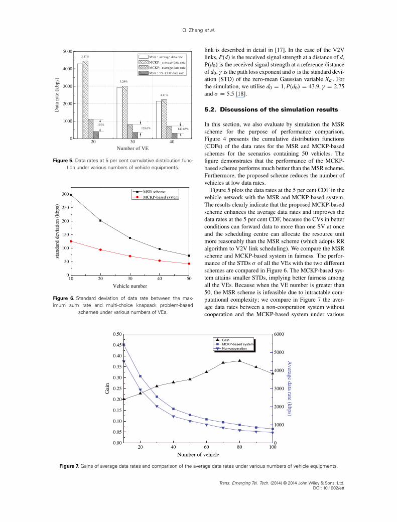
Figure 5 plots the data rates at the 5 per cent CDF in thevehicle network with the MSR and MCKP-based system.The results clearly indicate that the proposed MCKP-basedscheme enhances the average data rates and improves thedata rates at the 5 per cent CDF, because the CVs in betterconditions can forward data to more than one SV at onceand the scheduling centre can allocate the resource unitmore reasonably than the MSR scheme (which adopts RRalgorithm to V2V link scheduling). We compare the MSRscheme and MCKP-based system in fairness. The perfor-mance of the STDs � of all the VEs with the two differentschemes are compared in Figure 6. The MCKP-based sys-tem attains smaller STDs, implying better fairness amongall the VEs. Because when the VE number is greater than50, the MSR scheme is infeasible due to intractable com-putational complexity; we compare in Figure 7 the aver-age data rates between a non-cooperation system withoutcooperation and the MCKP-based system under various
20 40 60 80 1000.00
0.05
0.10
0.15
0.20
0.25
0.30
0.35
0.40
0.45
0.50
Number of vehicle
Gai
n
0
1000
2000
3000
4000
5000
6000
Average data rate (kbps)
Figure 7. Gains of average data rates and comparison of the average data rates under various numbers of vehicle equipments.
Trans. Emerging Tel. Tech. (2014) © 2014 John Wiley & Sons, Ltd.DOI: 10.1002/ett

Q. Zheng et al.
numbers of VEs. As shown in Figure 7, the right y-axisdepicts the average date rates of MCKP-based scheme andnon-cooperation, and the left y-axis represents the gains ofMCKP-based scheme relative to non-cooperation scheme.Figure 7 shows that the gains vary from 20 per cent to38 per cent under various number of vehicles.
6. CONCLUSION
In this paper, two modes of vehicular relay networks,that is, the 1-F-1 and 1-F-M, are discussed and analysedfirstly. A novel link allocation scheme is then proposedfor the 1-F-M relay network. An MCKP-based algorithmis employed to select CVs and to allocate resource unitsto the V2V links. In order to verify the advantages of theproposed scheme, a novel traffic simulation model is builtutilising the OPNET Modeler software, which can simu-late the traffic behaviour in a more realistic manner andresults in a more precise performance evaluation of differ-ent schemes. The simulation results show that the proposedscheme can obtain considerable improvement of the daterate, which is much higher than that of the MSR schemein the 1-F-1 mode of relay communication. Moreover,theMCKP-based approach is capable of achieving better fair-ness, enhancing significantly the data rates of the VEs inpoor channel conditions and also improves the averagethroughput of all VEs. In our future work, we are planningto study the V2V and V2I communications that both willbe served by the same communication system, that is, theLTE, in which interference and power consumption will beconsidered in vehicular networks.
ACKNOWLEDGEMENTS
This work is funded in part by the National Science Foun-dation of China (No.61331009), the Programme for NewCentury Excellent Talents in University (NCET-11-0600),and the Chinese Universities Scientific Fund under Grant2013RC0116.
REFERENCES
1. Seredynski M, Bouvry P. A survey of vehicular-basedcooperative traffic information systems. In 2011 14th
International IEEE Conference on Intelligent Trans-
portation Systems (ITSC), City: Washington, DC, 2011;163–168, DOI: 10.1109/ITSC.2011.6083055.
2. Kadas G, Chatzimisios P. Roadside Networks for Vehic-
ular Communications: Architectures, Applications and
Test Fields. IGI Global Press: Pennsylvania, 2012.3. IEEE standard for information technology– local and
metropolitan area networks– specific requirements– part11: Wireless lan medium access control (MAC) andphysical layer (PHY) specifications amendment 6: Wire-
less access in vehicular environments. IEEE Std 802.11p,
2010. DOI: 10.1109/IEEESTD.2010.5514475.
4. Ahmed MH, Syed I, Yanikomeroglu H. On the per-
formance of time division multiple access-based mul-
tihop fixed cellular networks with respect to available
frequency carriers. IET Communications 2008; 2 (9):
1196–1204. DOI: 10.1049/iet-com:20070490
5. Zheng K, Liu F, Zheng Q, Xiang W, Wang W.
A graph-based cooperative scheduling scheme for
vehicular networks. IEEE Transactions on Vehicular
Technology 2013; 62 (4): 1450–1458. DOI: 10.1109/
TVT.2013.2244929
6. Laneman JN, Tse DNC, Wornell GW. Cooperative
diversity in wireless networks: efficient protocols and
outage behavior. IEEE Transactions on Information
Theory 2004; 50 (12): 3062–3080. DOI: 10.1109/
TIT.2004.838089
7. Ilhan H, Altunbas I, Uysal M. Cooperative diver-
sity for relay-assisted inter-vehicular communication.
In IEEE Vehicular Technology Conference, 2008. VTC
Spring 2008, Singapore, 2008; 605–609, DOI: 10.1109/
VETECS.2008.135.
8. Ding Z, Leung KK. Cross-layer routing using cooper-
ative transmission in vehicular ad-hoc networks. IEEE
Journal on Selected Areas in Communications 2011;
29(3): 571–581. DOI: 10.1109/JSAC.2011.110307
9. Pyun SY, Cho DH, Son JW. Downlink resource allo-
cation scheme for smart antenna based v2v2i commu-
nication system. In IEEE Vehicular Technology Confer-
ence (VTC Fall), San Francisco, CA, 2011; 1–6, DOI:
10.1109/VETECF.2011.6092854.
10. Atat R, Yaacoub E, Alouini MS, Filali F. Delay
efficient cooperation in public safety vehicular net-
works using LTE and IEEE 802.11p. In IEEE Con-
sumer Communications and Networking Conference
(CCNC), Las Vegas, NV, 2012; 316–320, DOI: 10.1109/
CCNC.2012.6181109.
11. Zhou T, Sharif H, Hempel M, Mahasukhon P, Wang W,
Ma T. A novel adaptive distributed cooperative relaying
mac protocol for vehicular networks. IEEE Journal on
Selected Areas in Communications 2011; 29(1): 72–82.
DOI: 10.1109/JSAC.2011.110108
12. Tang X, Pu J, Gao Y, Alshehri MAZ, Xiong Z, Wan Y.
Knowledge-based replica deletion scheme using direc-
tional anti-packets for vehicular delay-tolerant networks.
Transactions on Emerging Telecommunications Tech-
nologies 2013, http://dx.doi.org/10.1002/ett.2685. DOI:
10.1002/ett.2685
13. Alsabaan M, Alasmary W, Albasir A, Naik K. Vehic-
ular networks for a greener environment: a survey.
IEEE Communications Surveys Tutorials 2013; 15 (3):
1372–1388. DOI: 10.1109/SURV.2012.101912.00184
Trans. Emerging Tel. Tech. (2014) © 2014 John Wiley & Sons, Ltd.DOI: 10.1002/ett

Q. Zheng et al.
14. Kellerer H, Perschy U, Pisinger D. Knapsack Problems.Springer: Berlin, 2004.
15. Wegener A, Hellbruck H, Wewetzer C, Lubke A.Vanet simulation environment with feedback loop andits application to traffic light assistance. In IEEEGLOBECOM Workshops, New Orleans, LO, 2008; 1–7,DOI: 10.1109/GLOCOMW.2008.ECP.67.
16. Krauss S. Microscopic Modelling of Traffic Flow: Inves-tigation of Collision Free Vehicle Dynamics. It is adoctoral dissertation in Universitat zu Koln, 1998.
17. 36.211 3GPP TS. Technical specification groupradio access network, December 2011. http://www.3gpp.org.
18. Cheng L, Benjamin H, Stancil DD, Bai F, Mudalige P.A fully mobile, gps enabled, vehicle-to-vehicle mea-surement platform for characterization of the 5.9 GHzdsrc channel. In IEEE Antennas and PropagationSociety International Symposium, Honolulu, HI, 2007;2005–2008, DOI: 10.1109/APS.2007.4395917.
Trans. Emerging Tel. Tech. (2014) © 2014 John Wiley & Sons, Ltd.DOI: 10.1002/ett