Vehicle Surrounding Supervision
9
Canadian Journal on Computing in Mathematics, Natural Sciences, Engineering and Medicine Vol. 3 No. 7, December 2012 277 Vehicle Surrounding Supervision Jer-Vui Lee, Yea-Dat Chuah, Eric C.H. Tan, Yee-Chuan Lau, En-Yen Phang, Chor-Zheng Tan, Chun-Sien Teh Abstract — The objective of this project is to design a mapping system which displays the surrounding of the vehicle by using ultrasonic sensor and graphical user interface (GUI) which provides maximum vehicle’s surveillance. Its mechanical and electronic hardware implementations as well as Java programming are discussed in this paper. 33 series dsPIC from Microchip Inc. is used in this system to work as peripheral interface between ultrasonic sensor, buzzer and Java-compatible-display device. Ultrasonic sensor rotated by drive of servo motor to achieve certain sensing coverage. PIC processes the sensor output and transfers this data to Java platform. A developed Java program is used to acquire and process the data from PIC, map the vehicle surrounding and it is displayed in graphics via the GUI. In addition, the casing of sensor is attached on a surface of car by using magnet and designed to allow the sensor to move within 180º (sensing coverage). Key Words — Vehicle supervision, mapping system, Java programming and PIC. I. INTRODUCTION The number of cars on the road has been increasing tremendously since few decades ago. The road accidents also in an upward trend due to the increment of the cars. Basically, the road accident has reached a significant number that really needs the concern of the country [1]. The traffic accidents that involve pedestrians commonly occur all around the world every year. Many pedestrians have been hurt or killed in the accidents. According to the statistics of The Pedestrian and Bicycle Information Centre (PBIC), there are 4280 pedestrian deaths and 70000 pedestrian injuries in United States in year 2010 [2]. Pedestrians are vulnerable and easily get hurt by clumsy car drivers. Sizes of pedestrians are relatively small compare to the vehicles and thus they are always neglected from the drivers’ sight. Therefore, there comes the development of driving aid systems with mapping. The main function of the driving aid system is to detect the obstacles that potentially bring harm to the vehicle and driver. Mapping system can be displayed on a graphical user interface, hence to assist the driver to obtain the surrounding information of the vehicle. There are mapping system with different sensors such as piezoelectric sensor, infrared sensor, microwave radar, ultrasonic sensor and laser scanner in the market [3-8]. But majority of the sensing technology nowadays still focus on the detection of vehicle. Ultrasonic sensors are also known as transceivers when they both send and receive. Basically the working principles of ultrasonic are similar to radar or sonar. They evaluate attributes of a target by interpreting the echoes from radio or sound waves respectively. However, ultrasonic sensors generate high frequency sound waves and evaluate the echo which is received back by the sensor. Sensors calculate the time interval between sending the signal and receiving the echo to determine the distance to an object. For automobile, its function is to emit and alarm by sound and display when approaching the obstacles. In this project, we try to further develop an ultrasonic driving aid system which able to detect pedestrians and obstacles that potentially harmful threaten the vehicles and drivers. II. METHODOLOGY A. The Basic Principle As shown in Figure 1, a sensor is used to send the signal and to receive the signal from the obstacle. Based on the reflected signal, the distance of the obstacle is calculated. The mechanism of ultrasonic sensor is to achieve the highest angle coverage for the sensor to detect the obstacle in the surroundings. By using multi-platform supported programming software, Java programming language, the data is acquired from the PIC and map the vehicle surrounding and it is displayed in a graphics so that it can be displayed on the screen for the driver to notice on the obstacles on the road. The dot displayed on the screen represents the obstacles detected. By referring to the screen, the driver will be able to react accordingly. Fig.1. Block diagram of the basic principle B. Tools Selection (I) Java Programming Java Programming Language was selected as the platform to develop an intuitive Graphical User Interface. Java is generally an object-oriented programming software which involves creating and manipulating objects, and making objects work together. Modular programs and reusable code is able to be generated through the usage of this platform. The powerful highlight of Java is that it is platform independent or in the other words it is multi- platform. In addition, we aim to make this Java program to be android compatible so that it is portable and provide greater mobility. Therefore, the users can use it via their smart phones or android tablet. (II) Ultrasonic Sensor Ultrasonic sensor offers two functions which are sending signal and receiving signal. Its main advantage is to calculate the distance to an object or obstacle by calculating the time interval between sending the signal and receiving the echo. Ultrasonic sensor model HC-SR04 is used for the system as shown in Figure 2. Sensing area or the coverage of a sensor is the first concern when choosing sensor. Since ultrasonic wave is emitted in a cone shape with certain effectual angle, it provides larger detecting area if compared to IR distance sensor which sensing area is only on a point or a straight line. This sensor detects object of maximum 5 meter away. This range is not enough for detect car from distance. The idea sensing distance would be 10 to 15 meter and needed to be increase when vehicle’s speed increases. Besides, the maximum sensing rate of this sensor is 20Hz and it is not fast enough to capture distance since it need to rotates for 180° in certain time.
-
Upload
independent -
Category
Documents
-
view
2 -
download
0
Transcript of Vehicle Surrounding Supervision

Canadian Journal on Computing in Mathematics, Natural Sciences, Engineering and Medicine Vol. 3 No. 7, December 2012
277
Vehicle Surrounding Supervision
Jer-Vui Lee, Yea-Dat Chuah, Eric C.H. Tan, Yee-Chuan Lau, En-Yen Phang, Chor-Zheng Tan, Chun-Sien Teh
Abstract — The objective of this project is to design a
mapping system which displays the surrounding of the vehicle
by using ultrasonic sensor and graphical user interface (GUI)
which provides maximum vehicle’s surveillance. Its
mechanical and electronic hardware implementations as well
as Java programming are discussed in this paper. 33 series
dsPIC from Microchip Inc. is used in this system to work as
peripheral interface between ultrasonic sensor, buzzer and
Java-compatible-display device. Ultrasonic sensor rotated by
drive of servo motor to achieve certain sensing coverage. PIC
processes the sensor output and transfers this data to Java
platform. A developed Java program is used to acquire and
process the data from PIC, map the vehicle surrounding and it
is displayed in graphics via the GUI. In addition, the casing of
sensor is attached on a surface of car by using magnet and
designed to allow the sensor to move within 180º (sensing
coverage).
Key Words — Vehicle supervision, mapping system, Java
programming and PIC.
I. INTRODUCTION
The number of cars on the road has been increasing tremendously since
few decades ago. The road accidents also in an upward trend due to the
increment of the cars. Basically, the road accident has reached a significant
number that really needs the concern of the country [1]. The traffic accidents
that involve pedestrians commonly occur all around the world every year.
Many pedestrians have been hurt or killed in the accidents. According to the
statistics of The Pedestrian and Bicycle Information Centre (PBIC), there are
4280 pedestrian deaths and 70000 pedestrian injuries in United States in year
2010 [2]. Pedestrians are vulnerable and easily get hurt by clumsy car drivers.
Sizes of pedestrians are relatively small compare to the vehicles and thus they
are always neglected from the drivers’ sight.
Therefore, there comes the development of driving aid systems with
mapping. The main function of the driving aid system is to detect the
obstacles that potentially bring harm to the vehicle and driver. Mapping
system can be displayed on a graphical user interface, hence to assist the
driver to obtain the surrounding information of the vehicle. There are mapping
system with different sensors such as piezoelectric sensor, infrared sensor,
microwave radar, ultrasonic sensor and laser scanner in the market [3-8]. But
majority of the sensing technology nowadays still focus on the detection of
vehicle.
Ultrasonic sensors are also known as transceivers when they both send and
receive. Basically the working principles of ultrasonic are similar to radar or
sonar. They evaluate attributes of a target by interpreting the echoes from
radio or sound waves respectively. However, ultrasonic sensors generate high
frequency sound waves and evaluate the echo which is received back by the
sensor. Sensors calculate the time interval between sending the signal and
receiving the echo to determine the distance to an object. For automobile, its
function is to emit and alarm by sound and display when approaching the
obstacles. In this project, we try to further develop an ultrasonic driving aid
system which able to detect pedestrians and obstacles that potentially harmful
threaten the vehicles and drivers.
II. METHODOLOGY
A. The Basic Principle
As shown in Figure 1, a sensor is used to send the signal and to receive the signal from the obstacle. Based on the reflected signal, the distance of the
obstacle is calculated. The mechanism of ultrasonic sensor is to achieve the
highest angle coverage for the sensor to detect the obstacle in the surroundings. By using multi-platform supported programming software, Java
programming language, the data is acquired from the PIC and map the vehicle
surrounding and it is displayed in a graphics so that it can be displayed on the screen for the driver to notice on the obstacles on the road. The dot displayed
on the screen represents the obstacles detected. By referring to the screen, the
driver will be able to react accordingly.
Fig.1. Block diagram of the basic principle
B. Tools Selection
(I) Java Programming
Java Programming Language was selected as the platform to develop an intuitive Graphical User Interface. Java is generally an object-oriented
programming software which involves creating and manipulating objects, and
making objects work together. Modular programs and reusable code is able to be generated through the usage of this platform. The powerful highlight of
Java is that it is platform independent or in the other words it is multi-
platform. In addition, we aim to make this Java program to be android compatible so that it is portable and provide greater mobility. Therefore, the
users can use it via their smart phones or android tablet.
(II) Ultrasonic Sensor
Ultrasonic sensor offers two functions which are sending signal and
receiving signal. Its main advantage is to calculate the distance to an object or obstacle by calculating the time interval between sending the signal and
receiving the echo. Ultrasonic sensor model HC-SR04 is used for the system
as shown in Figure 2. Sensing area or the coverage of a sensor is the first concern when choosing sensor. Since ultrasonic wave is emitted in a cone
shape with certain effectual angle, it provides larger detecting area if
compared to IR distance sensor which sensing area is only on a point or a straight line. This sensor detects object of maximum 5 meter away. This range
is not enough for detect car from distance. The idea sensing distance would be
10 to 15 meter and needed to be increase when vehicle’s speed increases. Besides, the maximum sensing rate of this sensor is 20Hz and it is not fast
enough to capture distance since it need to rotates for 180° in certain time.
Canadian Journal on Computing in Mathematics, Natural Sciences, Engineering and Medicine Vol. 3 No. 7, December 2012
278
Fig. 2. Ultrasonic sensor model HC-SR04
(III) PIC Microcontroller
PIC from MicroChip® is comparatively cheaper choice to implement in our project. It is considered cheap if compared to other same level product
from different brand such as NXP, ATLET, TEXAS, CYAN and so on. The
reason 33 series products being chosen among wide range of MicroChip® product is this series of PIC provides more peripherals that meet this research
project requirement. 4 input captures channel available in this PIC allows the
increases of sensor used in this project. If 16 series product being used, only 2 sensors are allowed to implement in this project which is not enough if this
system applied to a large vehicle. In addition, this PIC has plastic dual in line
package (PDIP) which makes the soldering of it PCB easier compared to surface mount device (SMD).
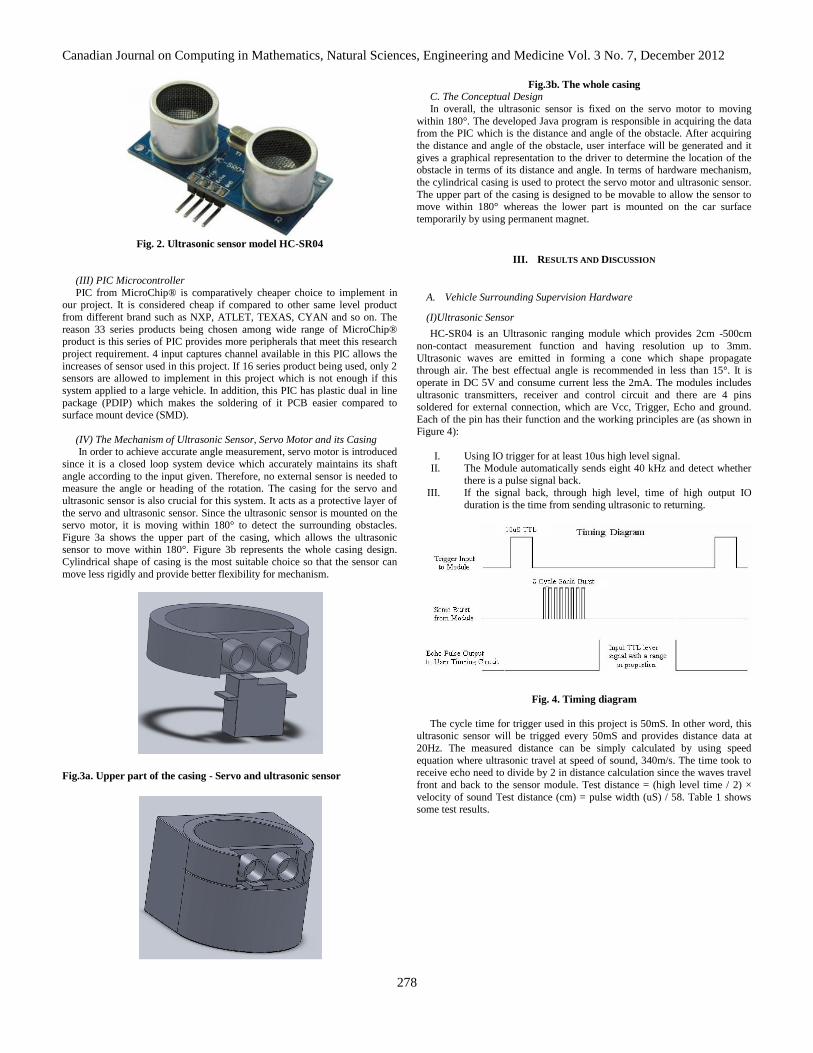
(IV) The Mechanism of Ultrasonic Sensor, Servo Motor and its Casing In order to achieve accurate angle measurement, servo motor is introduced
since it is a closed loop system device which accurately maintains its shaft
angle according to the input given. Therefore, no external sensor is needed to measure the angle or heading of the rotation. The casing for the servo and
ultrasonic sensor is also crucial for this system. It acts as a protective layer of
the servo and ultrasonic sensor. Since the ultrasonic sensor is mounted on the servo motor, it is moving within 180° to detect the surrounding obstacles.
Figure 3a shows the upper part of the casing, which allows the ultrasonic sensor to move within 180°. Figure 3b represents the whole casing design.
Cylindrical shape of casing is the most suitable choice so that the sensor can
move less rigidly and provide better flexibility for mechanism.
Fig.3a. Upper part of the casing - Servo and ultrasonic sensor
Fig.3b. The whole casing
C. The Conceptual Design
In overall, the ultrasonic sensor is fixed on the servo motor to moving
within 180°. The developed Java program is responsible in acquiring the data from the PIC which is the distance and angle of the obstacle. After acquiring
the distance and angle of the obstacle, user interface will be generated and it
gives a graphical representation to the driver to determine the location of the obstacle in terms of its distance and angle. In terms of hardware mechanism,
the cylindrical casing is used to protect the servo motor and ultrasonic sensor.
The upper part of the casing is designed to be movable to allow the sensor to move within 180° whereas the lower part is mounted on the car surface
temporarily by using permanent magnet.
III. RESULTS AND DISCUSSION
A. Vehicle Surrounding Supervision Hardware
(I)Ultrasonic Sensor
HC-SR04 is an Ultrasonic ranging module which provides 2cm -500cm
non-contact measurement function and having resolution up to 3mm.
Ultrasonic waves are emitted in forming a cone which shape propagate through air. The best effectual angle is recommended in less than 15°. It is
operate in DC 5V and consume current less the 2mA. The modules includes
ultrasonic transmitters, receiver and control circuit and there are 4 pins soldered for external connection, which are Vcc, Trigger, Echo and ground.
Each of the pin has their function and the working principles are (as shown in Figure 4):
I. Using IO trigger for at least 10us high level signal. II. The Module automatically sends eight 40 kHz and detect whether
there is a pulse signal back.
III. If the signal back, through high level, time of high output IO duration is the time from sending ultrasonic to returning.
Fig. 4. Timing diagram
The cycle time for trigger used in this project is 50mS. In other word, this ultrasonic sensor will be trigged every 50mS and provides distance data at
20Hz. The measured distance can be simply calculated by using speed
equation where ultrasonic travel at speed of sound, 340m/s. The time took to receive echo need to divide by 2 in distance calculation since the waves travel
front and back to the sensor module. Test distance = (high level time / 2) ×
velocity of sound Test distance (cm) = pulse width (uS) / 58. Table 1 shows
some test results.

Canadian Journal on Computing in Mathematics, Natural Sciences, Engineering and Medicine Vol. 3 No. 7, December 2012
279
Table 1: Table of test results
(II) Servo Motor
HD-1160A (as shown in Figure 5) is a micro size servo which having
torque of 2.7/6V kg/cm, which is sufficient for sensor mounting. These servos are supplied 5V in this project and moving no load except a ~50g ultrasonic
sensor while servo itself weighted 25g. Pulse Width Modulation (PWM) is
used to control the servo motor. The servo motor shaft rotation changes according to the high level time of the PWM, which called duty cycle. For the
position at neutral position or 90°, the high level time must be 1.5 ms. Hence,
the period of the PWM is set to 3mS so that the neutral position have 50% duty cycle. Decreases the duty cycle can changes the servo position toward 0°
while increase the duty cycle can changes toward 180°.
Fig. 5. HD-1160A Servo [11]
Since different servo have different characteristic, the servos in this research
project are pulsed from 0.5mS (15%) to 2.5mS (85%) and from 2.5mS to
0.5mS. This enables those servo motors to rotate 180° forward and backward repeatedly (as shown in Figure 6).
Fig. 6. Servo PWM control [12]
(III) Microcontroller The microcontroller used in this research project is PIC33128MC802 from
MicroChip Inc. as shown in Figure 7. It is a 33 series 16 bits microcontroller
operates in 3.3v. It is 28 pins plastic dual inline package (PDIP) and equipped with various peripheral such as PWM, UART, timer, SPI, I2C, input capture,
QEI and so on. A timer is used to periodically pulse the trigger pin of
ultrasonic sensor at 20Hz. While another timer used to periodically initiate UART send command for data communication purpose. Besides, 4 Input
captures ports are used to measure the high level time of the ultrasonic sensor
echo feedback. Two general IO ports used to control buzzer and servo calibration. PWM also produced by MCU for the servo control.
Fig. 7. PIC33FJ128MC802
(IV) UART Interface The UART interface device can be either wired or wireless (as shown in
Figure 8). UC00B Cytron USB-UART interface can be applied as wired device. It connects between UART molex pins on PCB and PC USB port.
While JY-MCU is a Bluetooth module that can be use as wireless channel.
Fig. 8. UC00B from Cytron and JY-MCU from JY
(V) Circuit and Board Design

Canadian Journal on Computing in Mathematics, Natural Sciences, Engineering and Medicine Vol. 3 No. 7, December 2012
280
EAGLE or Easily Applicable Graphical Layout Editor is free license software by Cadsoft which capable for schematic capture, PCB layout, auto-
router and CAM program. It has been use in this project on schematic drawing
and printed circuit board routing. The produced PCB sized 72mm x 73mm. It is a single layer board and required 2 jumper wires connection as shown in
Figure 9.
Fig. 9. PCB layout
B. Hardware Programming
(I) MPLAB MPLAB integrated development environment is a freeware distributed
from MicroChip®. Embedded applications which employing Microchip's
product (PIC® and dsPIC® microcontrollers) can use it as an integrated toolset for fast application development and super-charged debugging.
MPLAB V8.8 had been used in this project for dsPIC33 microcontroller C
language programming and hardware debugging. PIC-kit 2 is a programmer
design to program PIC microcontroller family. It uses PC’s USB to transfer
program compile by MPLAB to PIC flash by performing on board in circuit
serial programming (ICSP).
Fig. 10. PIC Kit 2
(II) Initialization
Initialization can be separated into 2, MCU and peripheral. MCU initialization includes CPU clock setting and pins multiplexing. In
MCU_Init() function, CPU clock has been setting to 39.32MHz by internal
FRC with PLL. Peripheral_Init() is a function used to assign peripheral to specific pins and disable peripheral which not in use.
(III) Timers There are 3 timers used in the program. Timer 1 has period of 50mS, used
to pulse to sensor’s trigger pin at 20Hz. Timer 3 has same period as timer 1,
50mS, used as the input capture referred timer. Input capture module will
capture timer 3 value when an event occurs. Timer 2 has shorter period, 12.8mS, used to initiate UART send functions at 78Hz.
(IV) PWM PWM signal generates by PIC output to servo motors to control the
heading of sensor which mounted on the servo motor’s shaft. Since the high
time required by servo motor to be at 90° is 1.5mS, the PWM frequency had set to 333Hz or period of 3ms so that when servo motor is 90°, the PWM duty
cycle is 50%. The duty cycle had set to 50% when initialization, all servo
motors are pulsed to turn to 90° position and stay. If the switch 2 is toggled, program now entered servo calibration mode. This allows user to perform
sensor-servo position calibration, which adjustment may took place on sensor
orientation and heading refer to the latest 90°. It aims to reduce offset and zero error of the angle calculation.
After the calibration, servo motors are pulsed to turn to 180° and back to 0°
and repeat. In other word, the sensor mounted on the servo will rotates or changes its heading 180° frontward and backward with certain angular
velocity. The maximum angular velocity the servo motor can have is
depending on the update rate of the sensor and the UART transfer rate.
Ultrasonic Sensor update rate = 20Hz
Time of 1 measurement = 1/ 20 = 0.05s
Servo motor angle resolution = 2°
Time of 180° measurement
Angular velocity of servo
(V) Input Capture
This peripheral used to measure the respond of the ultrasonic sensor
through echo pin. First, it needs to detect a raising edge and capture the time3 value. Then, detect a falling edge, capture timer3 value and the high time is
the deviation between these 2 captures. Then Input captures are programmed
to detect a falling edge only at initialization stage. After a falling edge detected, it changes to detect every edges, raising and falling. These detection
changing steps is useful in eliminating the possibility to detect low time
instead of high time. In other word, if the input capture is programmed to
detect every edge at initialization stage, it has 50% possible to 35 detect low
time because the echo sequence can’t be ensured. After a falling edge been
detected, the high time value will be updated accordingly.
(VI) Universal Asynchronous Receiver Transmitter
UART had applied in this project as the communication channel between PIC and PC. A consensus UART setting has applied on both end of the
channel. The UART module works with 9600 Hz baud rate, 8 bits data, 1 stop
bit, and no parity bit. The PC GUI update rate is depend on the UART transfer rate and can be calculated by the following formula:
Total bit sent = 1start bit + 8 data bits + 1 stop bit = 10 bits
Time of each send
Timer2 interrupt routine will initiate UART sending functions. 9 bytes are
queued to UART send function every timer2 interrupt. They are start byte, sensors heading angle and sensed distance. Sensors heading angle are taken
from PWM1 duty cycle value, while sensors sensed distance are taken from input capture result.
The minimum timer2 period can’t be less than 18.72m because transmit
request speed is faster than UART transmission speed and it will cause PIC program halt half way. However, this UART transmission speed needed to be
further reduces due to the speed of PC and Java Program serial data process
capability. In order to increase the efficiency of data communication, every bit in a byte sent must be useful. Instead of representing 30010 as 0000 0010
0101 11002 (30010), the program first divides the value to be sent by 2,
30010 as 1001 01102 (15010). Scaling down the value can effectively reduces the data byte to be sent and increase the communication efficiency by reduces
meaningless bit to be sent (few MSB of 2 bytes data). The maximum value 8
bits data can represent is 256, so sensor heading (0 to 360) needed to be divide

Canadian Journal on Computing in Mathematics, Natural Sciences, Engineering and Medicine Vol. 3 No. 7, December 2012
281
by 2 so that it maximum (180) don’t exist 256. While the maximum distance sensed output is 655 and it needed to be divide by 3 so that its maximum
(218) don’t exits the 8 bits data range limit
Fig. 11. Data set
Number of bytes to be send = 9 Time of each send = 2.08ms
Total time = 9 x 2.08m = 18.72ms
However, this scaling does brings disadvantage. The resolutions of the data
are further reduce by the factor of scaling. 1° and 1cm are the original sensor heading and sensed distance resolution; they become 2° and 3cm after the
scaling. Docklight had been used to monitor the data sent from PIC in this
project as shown in Figure 12. It is a testing, analysis and simulation tool for serial communication protocols, such as RS232, RS485 and so on. It allows
user to monitor the communication between two serial devices by displaying
data receives from serial ports and sending data to another device pair with the serial communication channel.
Fig. 12. Docklight interface and received data from PIC
(VII) PIC Program Flow The main() program as shown Figure 13 is very simple. It first initializes
the MCU clock and all other peripheral, and then waits for the servo motor
calibration to complete. After that, it run the servo motor by gradually increase and decrease the PWM duty cycle.
Fig. 13. Main() program flow chat
The interrupt routine run when a rising or falling edge event occurs at input capture assigned pins (as shown Figure 14). If it is the first interrupt, indicates
a falling edge detected and then change input capture module to capture every
edge. UP is 0 when next interrupt occurs, indicates a raising edge detected, time_a save the time3 value. When the next interrupt occurred, UP is 1 and
indicates a falling edge detected, time_b save the timer3 value. If the time_b
smaller than time_a, an overflow of timer3 had took place, a time3 period needed to be add to time_b before high period can be calculated.

Canadian Journal on Computing in Mathematics, Natural Sciences, Engineering and Medicine Vol. 3 No. 7, December 2012
282
Fig.14. Input capture interrupt routine
C. JAVA Graphical User Interface
In the development of a Java program the IDE chosen for this application is Eclipse as it has got a greater number of info available in the internet
regarding Java-Serial Interface. The first approach in developing software that
can process the data provided by hardware, dummy software is coded to test and develop the processing part of this. This dummy software has got an
interface as shown in Figure 15.
Fig. 15. Interface of dummy software
The dummy software has got no serial data acquisition capability at all and
only takes in data key in by the user but this is the first approach in designing the data processing and it works. The processing of this software is mainly
based on Pythagorean Theorem. The code below processes the Angle and
Range of the obstacle which resembles the angle and hypotenuse of a right angle triangle. Sine all the location of the sensor in the screen is predefined in
the software the right angle calculation is relative to the location of the sensor.
privateintsensor1x = 377+5;
privateintsensor2x = 377+5;
privateintsensor3x = 323+4; privateintsensor4x = 323+4;
privateintsensor1y = 306;
privateintsensor2y = 394; privateintsensor4y = 306;
privateintsensor3y = 394;
Fig. 16. Sample diagram with angle 120 degree
The above sample diagram shows that when the sensor is selected as 2 and
the Angle is 120 while the range is 50 so the calculated distance is 43 and 24.
The background calculation is as shown below:
Distance x = tan(angle)*range
Distance y = cos(angle)*range
Therefore there is actually no theoretical limitation of numbers of sensors to
be placed at the vehicle and there is only a different of resolution of the image mapped. But most of the time the sensors used is normally around 4 but in this
prototype only 2 is used. The sensor can be placed as shown Figure 17.
Configuration with 4 sensors:
Configuration with 3 sensors:
Configuration with 2 sensors: Configuration with 1 sensor:
Canadian Journal on Computing in Mathematics, Natural Sciences, Engineering and Medicine Vol. 3 No. 7, December 2012
283
Fig. 17. Different sensor configurations
Since java only process radian in its math function there for the data
collected from hardware which is in degree form has to be converted into radian format before processing. As shown below is the conversion code.
doubleangle_radian; angle_radian = Math.toRadians(degree);
After conversion, many of the math function available in the Java library can be used. For example the sinfunction of distance_x = (int)
(Math.sin(angle_radian)*-range); can be used without importing other 3rd
party library. All the data gathered are being rendered with condition of its color. As the code below:
Fig. 18. Math functions in the Java library
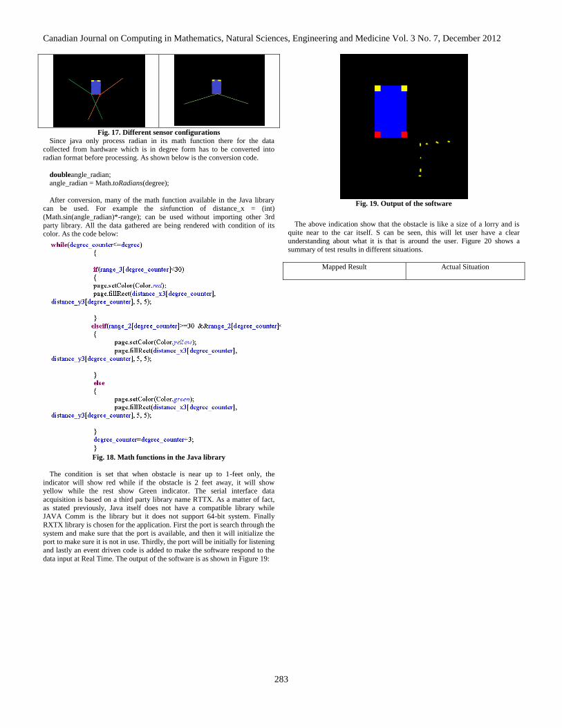
The condition is set that when obstacle is near up to 1-feet only, the
indicator will show red while if the obstacle is 2 feet away, it will show yellow while the rest show Green indicator. The serial interface data
acquisition is based on a third party library name RTTX. As a matter of fact,
as stated previously, Java itself does not have a compatible library while JAVA Comm is the library but it does not support 64-bit system. Finally
RXTX library is chosen for the application. First the port is search through the
system and make sure that the port is available, and then it will initialize the port to make sure it is not in use. Thirdly, the port will be initially for listening
and lastly an event driven code is added to make the software respond to the
data input at Real Time. The output of the software is as shown in Figure 19:
Fig. 19. Output of the software
The above indication show that the obstacle is like a size of a lorry and is
quite near to the car itself. S can be seen, this will let user have a clear
understanding about what it is that is around the user. Figure 20 shows a
summary of test results in different situations.
Mapped Result
Actual Situation

Canadian Journal on Computing in Mathematics, Natural Sciences, Engineering and Medicine Vol. 3 No. 7, December 2012
284
Fig. 20. Summary of test results in different situations
D. Hardware Mechanism
Simple servo programming is needed for the hardware mechanism to react when the driver decides to switch off the system when it is raining or other
situation. Switch of the ultrasonic sensor controls the on/off states of
ultrasonic sensor is depending on the driver if the sensor needs to be used. Figure 21a and 21b below shows the configurations of the ultrasonic sensor
when it is switched on and switched off. When the sensor is switched on, the
sensor will be face outward to detect if there is any barrier or obstacle. On the other hand, when it is switched off, it will appear to be inactive and it does not
send out the signal nor receiving the signal. Figure 22 shows a working
prototype of the system.
Fig. 21a. On State
Fig. 21b. Off State
Fig. 22. A working prototype
IV. CONCLUSION
This project aims to reduce possible car accidents to map the
surrounding of the vehicles by using ultrasonic sensor. Literature review results show that the blind spot has always been a problem to
driver and one of the causes of car accident. Blind spot is sometimes
an issue that the driver could not really see the surrounding obstacles. Besides, drivers tend to be unable to see the surrounding in every

Canadian Journal on Computing in Mathematics, Natural Sciences, Engineering and Medicine Vol. 3 No. 7, December 2012
285
corner of the car. So, by mapping of surrounding obstacles, the driver can have a clear understanding of the surrounding. Therefore, the objective has
been fully met throughout the project. The aim of project of ultrasonic sensor
to map the surrounding of the vehicles has been achieved. When the surrounding obstacles have been sensed, the develop Java program will map
the surrounding obstacles and display on the screen.
Nevertheless, there are some limitations in this project which needs to be improved. In the project, the sensor is planned to have 180 degree of sensing
coverage. However, once the casing has been put on it, the sensing coverage
of the sensor has reduced which less than 180 degree. In addition, the sensing distance has been limited to only 5 meters away. Once the distance is far away
from 5 meters, the result will not accurate. In addition, due to the processing
speed of the Java programming is considered slow, so the update rate of output will be affected and might be lagging. The maximum of the sensors
that can be used are up to 4 pieces because the maximum input capture
channels of PIC are up to 4. Although Java Programming is compatible to most of the devices, there are some devices like some of the mobile phones or
non-smart-phone cannot be supported.
REFERENCES
[1] Mustafa, M. N. “Overview of current road safety situation in Malaysia”,
Road Safety Situation In Malaysia, 2006. [2] Pedestrian crash facts. (n.d.) NHTSA’s National Center for Statistics
and Analysis, 2012. [3] Qian & Han, “The Applications and Methods of Pedestrian Automated
Detection”, International Conference on Measuring Technology and
Mechatronics Automation (ICMTMA), 2010. [4] Carullo, A., & Marco, P. “An ultrasonic sensor for distance
measurement in automotive applications”, Sensors Journal, IEEE, vol. 1,
no. 2, 2001. [5] Kai-Tai, S., Chih-Hao, C., & Cheng-Hsien Chiu, H. “Design and
experimental study of an ultrasonic sensor system for lateral collision
avoidance at low speeds”, Intelligent Vehicles Symposium, IEEE, pp. 647-652, 2004.
[6] Fred, Y., Bozena, K., & Pawel, G. “A new driving assistant for
automobiles”. Canadian Conference on Electrical and Computer Engineering, 2007, pp. 1199-1202, 2007.
[7] Uvais, Q. “Fuzzy blind-spot scanner for automobiles”, IEEE
Symposium on Industrial Electronics & Applications, 2, pp. 758-763, 2009.
[8] Kukko, A., Jaakkola, A., Lehtomäki, M., & Kaartinen, H. “Mobile
mapping system and computing methods for modelling of road environment’, Urban Remote Sensing Event, 2009 Joint, pp. 1-6, 2009.
BIOGRAPHIES
Dr. Lee Jer-Vui is an Assistant Professor in the Department of Mechatronics and BioMedical
Engineering, Faculty of Engineering & Science, Tunku
Abdul Rahman University, Malaysia. His research interests are in the field of automation and robotics.
Chuah Yea-Dat is a lecturer in the Department of Mechatronics and BioMedical Engineering, Faculty of
Engineering & Science, Tunku Abdul Rahman
University, Malaysia. His research interests are in the field of mechatronics and biomedical engineering
system design.
Eric Tan Cheng Hoong is a final year student in the
Department of Mechatronics and BioMedical Engineering, Faculty of Engineering & Science, Tunku
Abdul Rahman University, Malaysia. His research
interest is in the field of mechatronics system design.
Lau Yee-Chuan is a final year student in the
Department of Mechatronics and BioMedical
Engineering, Faculty of Engineering & Science, Tunku Abdul Rahman University, Malaysia. His research
interest is in the field of mechatronics system design.
Puang En-Yen is a final year student in the
Department of Mechatronics and BioMedical Engineering, Faculty of Engineering & Science, Tunku
Abdul Rahman University, Malaysia. His research
interest is in the field of mechatronics system design.
Tan Chor-Zheng is a final year student in the
Department of Mechatronics and BioMedical
Engineering, Faculty of Engineering & Science, Tunku Abdul Rahman University, Malaysia. His research
interest is in the field of mechatronics system design.
Teh Chun-Sien is a final year student in the
Department of Mechatronics and BioMedical Engineering, Faculty of Engineering & Science, Tunku
Abdul Rahman University, Malaysia. His research
interest is in the field of mechatronics system design.