Gires-Tournois interferometer type negative dispersion mirrors for deep ultraviolet pulse...
10
Gires-Tournois interferometer type negative dispersion mirrors for deep ultraviolet pulse compression Christopher A. Rivera, 1 Stephen E. Bradforth, 1,* and Gabriel Tempea 2 1 Department of Chemistry, University of Southern California, Los Angeles 90089-0482, California, USA 2 Femtolasers Produktions GmbH, Fernkorngasse 10, 1100 Vienna, Austria *[email protected] Abstract: Typical femtosecond pulse compression of deep ultraviolet radiation consists of prism or diffraction grating pair chirp compensation but, both techniques introduce higher-order dispersion, spatial-spectral beam distortion and poor transmission. While negatively chirped dielectric mirrors have been used to compress near infrared and visible pulses to <10 fs, there has been no extension of this technique below 300 nm. We demonstrate the use of Gires-Tournois interferometer (GTI) negative dispersion multilayer dielectric mirrors designed for pulse compression in the deep ultraviolet region. GTI mirror designs are more robust than chirped mirrors and, can provide sufficient bandwidth for the compression of sub- 30-fs pulses in the UV wavelength range. Compression of a 5 nm (FWHM) pulse centered between 266 and 271 nm to 30 fs has been achieved with less pulse broadening due to high-order dispersion and no noticeable spatial deformation, thereby improving the resolution of ultrafast techniques used to study problems such as fast photochemical reaction dynamics. ©2010 Optical Society of America OCIS codes: (320.0320) Ultrafast optics; (320.5520) Pulse compression; (230.2035) Dispersion compensation devices; (260.7190) Ultraviolet. References and links 1. M. Yamashita, M. Ishikawa, K. Torizuka, and T. Sato, “Femtosecond-pulse laser chirp compensated by cavity- mirror dispersion,” Opt. Lett. 11(8), 504–506 (1986). 2. P. Dombi, P. Rácz, M. Lenner, V. Pervak, and F. Krausz, “Dispersion management in femtosecond laser oscillators with highly dispersive mirrors,” Opt. Express 17(22), 20598–20604 (2009). 3. X. Chen, L. Canova, A. Malvache, A. Jullien, R. Lopez-Martens, C. Durfee, D. Papadopoulos, and F. Druon, “1- mJ, sub-5-fs carrier-envelope phase-locked pulses,” Appl. Phys. B 99(1-2), 149–157 (2010). 4. C. F. Dutin, A. Dubrouil, S. Petit, E. Mével, E. Constant, and D. Descamps, “Post-compression of high-energy femtosecond pulses using gas ionization,” Opt. Lett. 35(2), 253–255 (2010). 5. R. Szipocs, K. Ferencz, C. Spielmann, and F. Krausz, “Chirped multilayer coatings for broadband dispersion control in femtosecond lasers,” Opt. Lett. 19(3), 201–203 (1994). 6. I. Matsuda, K. Misawa, and R. Lang, “Femtosecond chirp-variable apparatus using a chirped mirror pair for quantum coherent control,” Opt. Commun. 239(1-3), 181–186 (2004). 7. V. Pervak, F. Krausz, and A. Apolonski, “Dispersion control over the ultraviolet-visible-near-infrared spectral range with HfO2/SiO2-chirped dielectric multilayers,” Opt. Lett. 32(9), 1183–1185 (2007). 8. Y. Kida, S. Zaitsu, and T. Imasaka, “Generation of intense 11-fs ultraviolet pulses using phase modulation by two types of coherent molecular motions,” Opt. Express 16(18), 13492–13498 (2008). 9. A. S. Morlens, P. Balcou, P. Zeitoun, C. Valentin, V. Laude, and S. Kazamias, “Compression of attosecond harmonic pulses by extreme-ultraviolet chirped mirrors,” Opt. Lett. 30(12), 1554–1556 (2005). 10. C. G. Durfee Iii, S. Backus, M. M. Murnane, and H. C. Kapteyn, “Ultrabroadband phase-matched optical parametric generation in the ultraviolet by use of guided waves,” Opt. Lett. 22(20), 1565–1567 (1997). 11. C. G. Durfee 3rd, S. Backus, H. C. Kapteyn, and M. M. Murnane, “Intense 8-fs pulse generation in the deep ultraviolet,” Opt. Lett. 24(10), 697–699 (1999). 12. N. Krebs, R. A. Probst, and E. Riedle, “Sub-20 fs pulses shaped directly in the UV by an acousto-optic programmable dispersive filter,” Opt. Express 18(6), 6164–6171 (2010). 13. K. Kosma, S. A. Trushin, W. E. Schmid, and W. Fuss, “Vacuum ultraviolet pulses of 11 fs from fifth-harmonic generation of a Ti:sapphire laser,” Opt. Lett. 33(7), 723–725 (2008). #131278 - $15.00 USD Received 13 Jul 2010; revised 10 Aug 2010; accepted 10 Aug 2010; published 16 Aug 2010 (C) 2010 OSA 30 August 2010 / Vol. 18, No. 18 / OPTICS EXPRESS 18615
-
Upload
independent -
Category
Documents
-
view
2 -
download
0
Transcript of Gires-Tournois interferometer type negative dispersion mirrors for deep ultraviolet pulse...

Gires-Tournois interferometer type negative
dispersion mirrors for deep ultraviolet pulse
compression
Christopher A. Rivera,1 Stephen E. Bradforth,
1,* and Gabriel Tempea
2
1Department of Chemistry, University of Southern California, Los Angeles 90089-0482, California, USA 2Femtolasers Produktions GmbH, Fernkorngasse 10, 1100 Vienna, Austria
Abstract: Typical femtosecond pulse compression of deep ultraviolet
radiation consists of prism or diffraction grating pair chirp compensation
but, both techniques introduce higher-order dispersion, spatial-spectral
beam distortion and poor transmission. While negatively chirped dielectric
mirrors have been used to compress near infrared and visible pulses to <10
fs, there has been no extension of this technique below 300 nm. We
demonstrate the use of Gires-Tournois interferometer (GTI) negative
dispersion multilayer dielectric mirrors designed for pulse compression in
the deep ultraviolet region. GTI mirror designs are more robust than chirped
mirrors and, can provide sufficient bandwidth for the compression of sub-
30-fs pulses in the UV wavelength range. Compression of a 5 nm (FWHM)
pulse centered between 266 and 271 nm to 30 fs has been achieved with less
pulse broadening due to high-order dispersion and no noticeable spatial
deformation, thereby improving the resolution of ultrafast techniques used
to study problems such as fast photochemical reaction dynamics.
©2010 Optical Society of America
OCIS codes: (320.0320) Ultrafast optics; (320.5520) Pulse compression; (230.2035) Dispersion
compensation devices; (260.7190) Ultraviolet.
References and links
1. M. Yamashita, M. Ishikawa, K. Torizuka, and T. Sato, “Femtosecond-pulse laser chirp compensated by cavity-
mirror dispersion,” Opt. Lett. 11(8), 504–506 (1986).
2. P. Dombi, P. Rácz, M. Lenner, V. Pervak, and F. Krausz, “Dispersion management in femtosecond laser
oscillators with highly dispersive mirrors,” Opt. Express 17(22), 20598–20604 (2009).
3. X. Chen, L. Canova, A. Malvache, A. Jullien, R. Lopez-Martens, C. Durfee, D. Papadopoulos, and F. Druon, “1-
mJ, sub-5-fs carrier-envelope phase-locked pulses,” Appl. Phys. B 99(1-2), 149–157 (2010).
4. C. F. Dutin, A. Dubrouil, S. Petit, E. Mével, E. Constant, and D. Descamps, “Post-compression of high-energy
femtosecond pulses using gas ionization,” Opt. Lett. 35(2), 253–255 (2010).
5. R. Szipocs, K. Ferencz, C. Spielmann, and F. Krausz, “Chirped multilayer coatings for broadband dispersion
control in femtosecond lasers,” Opt. Lett. 19(3), 201–203 (1994).
6. I. Matsuda, K. Misawa, and R. Lang, “Femtosecond chirp-variable apparatus using a chirped mirror pair for
quantum coherent control,” Opt. Commun. 239(1-3), 181–186 (2004).
7. V. Pervak, F. Krausz, and A. Apolonski, “Dispersion control over the ultraviolet-visible-near-infrared spectral
range with HfO2/SiO2-chirped dielectric multilayers,” Opt. Lett. 32(9), 1183–1185 (2007).
8. Y. Kida, S. Zaitsu, and T. Imasaka, “Generation of intense 11-fs ultraviolet pulses using phase modulation by
two types of coherent molecular motions,” Opt. Express 16(18), 13492–13498 (2008).
9. A. S. Morlens, P. Balcou, P. Zeitoun, C. Valentin, V. Laude, and S. Kazamias, “Compression of attosecond
harmonic pulses by extreme-ultraviolet chirped mirrors,” Opt. Lett. 30(12), 1554–1556 (2005).
10. C. G. Durfee Iii, S. Backus, M. M. Murnane, and H. C. Kapteyn, “Ultrabroadband phase-matched optical
parametric generation in the ultraviolet by use of guided waves,” Opt. Lett. 22(20), 1565–1567 (1997).
11. C. G. Durfee 3rd, S. Backus, H. C. Kapteyn, and M. M. Murnane, “Intense 8-fs pulse generation in the deep
ultraviolet,” Opt. Lett. 24(10), 697–699 (1999).
12. N. Krebs, R. A. Probst, and E. Riedle, “Sub-20 fs pulses shaped directly in the UV by an acousto-optic
programmable dispersive filter,” Opt. Express 18(6), 6164–6171 (2010).
13. K. Kosma, S. A. Trushin, W. E. Schmid, and W. Fuss, “Vacuum ultraviolet pulses of 11 fs from fifth-harmonic
generation of a Ti:sapphire laser,” Opt. Lett. 33(7), 723–725 (2008).
#131278 - $15.00 USD Received 13 Jul 2010; revised 10 Aug 2010; accepted 10 Aug 2010; published 16 Aug 2010(C) 2010 OSA 30 August 2010 / Vol. 18, No. 18 / OPTICS EXPRESS 18615

14. S. A. Trushin, W. Fuss, K. Kosma, and W. E. Schmid, “Widely tunable ultraviolet sub-30-fs pulses from
supercontinuum for transient spectroscopy,” Appl. Phys. B 85(1), 1–5 (2006).
15. S. A. Trushin, K. Kosma, W. Fuss, and W. E. Schmid, “Sub-10-fs supercontinuum radiation generated by
filamentation of few-cycle 800 nm pulses in argon,” Opt. Lett. 32(16), 2432–2434 (2007).
16. M. Beutler, M. Ghotbi, F. Noack, D. Brida, C. Manzoni, and G. Cerullo, “Generation of high-energy sub-20 fs
pulses tunable in the 250-310 nm region by frequency doubling of a high-power noncollinear optical parametric
amplifier,” Opt. Lett. 34(6), 710–712 (2009).
17. I. Walmsley, L. Waxer, and C. Dorrer, “The role of dispersion in ultrafast optics,” Rev. Sci. Instrum. 72(1), 1–29
(2001).
18. A. E. Jailaubekov, and S. E. Bradforth, “Tunable 30-femtosecond pulses across the deep ultraviolet,” Appl. Phys.
Lett. 87(2), 021107 (2005).
19. C. H. Brito Cruz, P. C. Becker, R. L. Fork, and C. V. Shank, “Phase correction of femtosecond optical pulses
using a combination of prisms and gratings,” Opt. Lett. 13(2), 123–125 (1988).
20. B. J. Pearson, and T. C. Weinacht, “Shaped ultrafast laser pulses in the deep ultraviolet,” Opt. Express 15(7),
4385–4388 (2007).
21. C. H. Tseng, S. Matsika, and T. C. Weinacht, “Two-dimensional ultrafast fourier transform spectroscopy in the
deep ultraviolet,” Opt. Express 17(21), 18788–18793 (2009).
22. G. Steinmeyer, “Dispersion compensation by microstructured optical devices in ultrafast optics,” Appl. Phys., A
Mater. Sci. Process. 79(7), 1663–1671 (2004).
23. G. Steinmeyer, “Femtosecond dispersion compensation with multilayer coatings: toward the optical octave,”
Appl. Opt. 45(7), 1484–1490 (2006).
24. M. J. Tauber, R. A. Mathies, X. Y. Chen, and S. E. Bradforth, “Flowing liquid sample jet for resonance Raman
and ultrafast optical spectroscopy,” Rev. Sci. Instrum. 74(11), 4958–4960 (2003).
25. A. W. Snyder, and J. D. Love, Optical Waveguide Theory (Chapman and Hall, 1983).
26. A. C. Moskun, A. E. Jailaubekov, S. E. Bradforth, G. H. Tao, and R. M. Stratt, “Rotational coherence and a
sudden breakdown in linear response seen in room-temperature liquids,” Science 311(5769), 1907–1911 (2006).
27. Z. Y. Li, D. Abramavicius, W. Zhuang, and S. Mukamel, “Two-dimensional electronic correlation spectroscopy
of the n pi* and pi pi* protein backbone transitions: A simulation study,” Chem. Phys. 341(1-3), 29–36 (2007).
28. D. Abramavicius, J. Jiang, B. M. Bulheller, J. D. Hirst, and S. Mukamel, “Simulation study of chiral two-
dimensional ultraviolet spectroscopy of the protein backbone,” J. Am. Chem. Soc. 132(22), 7769–7775 (2010).
Introduction
Dispersive mirrors (DMs) are becoming increasingly popular for any application where
dispersion control, especially group delay dispersion (GDD) compensation for compression of
ultrashort pulses is required. The use of DMs as intracavity mirrors in ultrafast laser systems
[1], and for pulse compression of high energy Ti:S amplified systems [2–4] remain the most
common applications due to the high damage thresholds, high reflectivity, and good spatial
mode preservation of DM-coatings [5]. Furthermore, DM-based dispersion compensators are
compact, robust and user-friendly. Manipulation of the linear chirp rate can also be used for
quantum coherent control resulting in the observation of, for example, chirp-dependent
fluorescence [6]. Recently, advances in engineering and the introduction of various high and
low index materials, such as HfO2 and SiO2, have extended DM applications and commercial
products to the UV spectral range down to 350 nm [7,8]. Additionally, designs for Mo/Si
chirped mirrors (CMs) have been published for attosecond pulses in the XUV [9].
For chemists and physicist working in the deep ultraviolet (200-300 nm), there has been
significant progress made in the efficient generation of broadband pulses by four wave mixing
in fibers or in gas cells which have allowed for the observation of dynamics on a timescale
hitherto unobtainable [10–16]. Unfortunately, delivery of laser light to an experimental
apparatus generally requires transmissive optics such as lenses, windows, waveplates, etc.
which introduce significant temporal broadening [17]. There are several ways to control phase
dispersion of optical pulses each with advantages and drawbacks. Prism compression
generally results in good efficiency (~75%) but substantial third-order dispersion (TOD) is
observed [18] and precise prism matching is needed in order to avoid significant spatial-
spectral and mode distortion. Grating compression generally results in less TOD but increased
fourth order dispersion (FOD) and poor transmission in the UV (< 50% even in a single pass
configuration) and similar problems from spatial chirp are also unavoidable [11].
Theoretically, combinations of prisms and gratings could be used to compensate both second
and third order dispersion [19] but will improve neither spatial dispersion, transmission losses
#131278 - $15.00 USD Received 13 Jul 2010; revised 10 Aug 2010; accepted 10 Aug 2010; published 16 Aug 2010(C) 2010 OSA 30 August 2010 / Vol. 18, No. 18 / OPTICS EXPRESS 18616

nor FOD-compensation. Pulse shapers use long (50 - 75 mm) KDP crystals to precisely
control the phase of pulses throughout the UV range (250 - 400 nm). These can be used to
achieve near perfect Fourier-limited pulses (< 20 fs) or can be used to generate multi pulse
schemes in the time domain for 2D spectroscopies [12,20,21]. Unfortunately, very low
transmission efficiency (~20%), significant spatial chirp, parallel displacement of diffracted
sub-pulses and high cost all complicate the implementation and usefulness of pulse shapers
for typical pump-probe experiments where the main objective is maximum time resolution.
In this paper, we present to our knowledge the first set of negative dispersion mirrors
designed to compress pulses in the DUV. We show that we can produce 30 fs pulses while
taking advantage of the high reflectivity and minimal spatial dispersion which typically make
dispersive mirrors attractive for applications in the visible and IR [22,23], and the added
control over higher order dispersion improves the compression efficiency over standard prism
and grating compensating methods. We show that this DM compressor is effective used in
combination with a hollow core fiber DUV frequency source pumped by 35 - 100 fs Ti:Sa
amplifier systems and that the compressor can be tuned over at least a 6 nm range from 266 to
272 nm for pulses that have ~5 nm of bandwidth.
Experimental setup
Two amplified laser systems were employed to produce deep UV pulses and fully test the
capabilities of the DM compressor. (i) A portion of the output of a 800 µJ, 110 fs, 1 kHz
Ti:sapphire regenerative amplifier (Spectra Physics Hurricane) shown in Fig. 1 was doubled
in a long (500 µm thick) BBO which was combined with the residual 800 nm to drive a
hollow core fiber four wave mixing (FWM) apparatus to generate pulses having broad
bandwidth in the deep UV. This difference-frequency mixing of second-harmonic light (65
µJ) with residual fundamental (65 µJ) was used to generate 4 µJ of 266 nm third-harmonic (3ω
= 2ω + 2ω – ω) as demonstrated previously [18]. A typical pulse centered at 266.5 nm with
4.9 nm FWHM, assuming Gaussian pulse shape, was measured with an EPP2000 UV2 200-
400 nm spectrometer (StellarNet Inc.) and is shown in Fig. 2. (ii) Similarly, a portion of
output of a 3.5 mJ, 35 fs, 1 kHz Ti:sapphire regenerative amplifier (Coherent Legend USP-
HE) was used to pump an identical hollow core fiber system. In this case the same 500 µm
BBO was used to produce 70 µJ of 400 nm and this was combined with 115 µJ of residual
fundamental to produce 5 µJ of 271.5 nm. The spectrum of a pulse with 5.2 nm of bandwidth
from this latter system is also shown in Fig. 2. The difference in center frequency of the
generated third-harmonic light is a result of the larger fundamental bandwidth of system (ii),
resulting in a small amount of tunability when overlapping with the second-harmonic in the
hollow core fiber. The output of the hollow waveguide DUV source was collimated by a
custom low-dispersion curved dielectric mirror with a radius of curvature of −70 cm and
steered into a DM pair before being sent into an autocorrelator. The DUV beam was split,
then characterized in an interferometer by measuring the simultaneous two-photon absorption
generated by overlapping the two beams spatially and temporally in a 100 µm jet of flowing
liquid water [18,24]. The autocorrelation traces were collected by scanning a delay stage in
one arm of the interferometer and measuring the change in absorption as a function of delay
time. Identical material and number of coated surfaces are present in each arm.
#131278 - $15.00 USD Received 13 Jul 2010; revised 10 Aug 2010; accepted 10 Aug 2010; published 16 Aug 2010(C) 2010 OSA 30 August 2010 / Vol. 18, No. 18 / OPTICS EXPRESS 18617

Fig. 1. Experimental setup. Third harmonic light is generated in a hollow core fiber and auto-
correlated in a thin film water jet as described in 17. DMA and DMB correspond to the
dispersive mirror pair and M4 to the 0° low dispersion dielectric mirror that makes up the
compressor. DMA and M4 can be translated to control the number of bounces per dispersive
mirror and the angle of the DM setup can also be varied. W is a pair of Suprasil optical wedges.
CHR is a curved low dispersion dielectric high reflector (f = 35 cm). M1, M2 and M3 are low
dispersion 0° and 45° dielectric high reflectors.
The DM mirrors are 20x40x10 mm and were designed to compensate for ~50 fs2 of GDD
and ~12.5 fs3 of TOD per bounce, as well as to have 99% reflectivity at 268 nm at 7° angle of
incidence (AOI) from perpendicular to the mirror substrate. The GTI-like design consisted of
a high-reflecting 42-layer quarter-wave stack, a half-wave high-index spacing layer and a
partially-reflecting two-layer quarter-wave section. HfO2 and SiO2 were employed as coating
materials. In chirped mirror designs the frequency dependence of the group delay imparted
upon reflection is controlled by means of the penetration of the different wavepackets into the
multilayer; consequently, all layer thicknesses will sensitively affect the GDD of the mirror.
Layer thickness accuracies in the range of 0.5 nm are required for the manufacturing of CMs
for the visible and infrared spectral range. Since the average layer thickness of CMs (and
consequently the acceptable layer thickness tolerance) scales roughly linearly with the central
wavelength, an absolute layer thickness accuracy in the range of 1 Angstrom would be
required in order to manufacture CMs for the sub-300-nm wavelength range. This is hardly
achievable with any state of the art deposition technique for dielectric optical layers. In
contrast to CMs, GTI-like dispersive mirrors are much more robust; deviations in the layers
thicknesses of the two quarter-wave stacks hardly affect the GDD of the mirror at all, while
deviations of the spacer layer thickness from the theoretical design value merely result in a
spectral shift of the mirror characteristics. This spectral shift can be simply determined from a
transmittance measurement where the position of side bands of the highly-reflective region of
the mirror can be used to estimate the error in the thickness of the resonator layer.
The designed GDD curve and actual GDD curve derived from the theoretical and
measured transmittance of the GTI-DMs are shown in Fig. 2. The GTI mirrors were designed
to compress a DUV pulse with 5 nm FWHM to ~1.22x the transform limit. By tuning the
angle of incidence it is possible to shift the optimal wavelength of GDD compensation
although this will result in a change of the compression capabilities of the DMs. An increase
in the AOI results in a blue shift of this curve, while decreasing the AOI causes a red shift
(Fig. 3). The amount of GDD compensation at the optimal wavelength also varies depending
on the polarization of the incoming pulse. For p-polarized light the amount of GDD decreases
#131278 - $15.00 USD Received 13 Jul 2010; revised 10 Aug 2010; accepted 10 Aug 2010; published 16 Aug 2010(C) 2010 OSA 30 August 2010 / Vol. 18, No. 18 / OPTICS EXPRESS 18618

with increasing AOI while for s-polarized light the GDD compensation increases. In our
setup, the third harmonic out of the waveguide is s-polarized with respect to the DM. In the
case of both s- and p-polarization, an increase in AOI results in a decrease in the reflectivity.
The coating process was expected to have a ± 1% error with respect to the optimal
compensation wavelength which is well substantiated by Fig. 2 indicating a 2.5 nm shift
between the theoretical and the reverse-engineered dispersion curves. Since a spectral
interferogram from a broadband Michelson interferometer would be required to measure the
actual GDD curves, a capability we do not currently have, the actual GDD properties of the
DMs still have to be thoroughly tested by performing pulse compression on a DUV ultrafast
pulse.
Fig. 2. Dispersive mirror GDD curves designed (thick black) and manufactured (red) for
optimal reflectivity at 7° AOI. Typical 266.5 and 271.5 nm spectra (thin black) with 4.9 and 5.2
nm FWHM respectively produced from FWM in an argon-filled hollow core fiber.
To minimize the total amount of group delay dispersion requiring compensation from the
addition of the necessary optical components in the beam path, all reflective surfaces are
custom low-dispersion 268 nm dielectric mirrors and all focusing was done with custom low-
dispersion curved 268 nm dielectric mirrors supplied by Femtolasers. Only two transmissive
optics were used in the DUV optical path: the beam splitter in the interferometer consisted of
a 1.6 mm thick CaF2 window (CVI) with a UV anti-reflection coating on the second surface,
and the back window of the fiber cell was a 1 mm piece of uncoated CaF2. Using the
estimated dispersion characteristics of air, and all optical components in the DUV optical line
(except the DM compensating components) the total estimated GDD and TOD at 266.5 nm
are 865 ± 50 fs2 and 260 ± 12 fs
3, and at 271.5 nm, 914 ± 50 fs
2 and 280 ± 10 fs
3 respectively.
The DUV path length was approximately 0.84 m longer in the latter setup accounting for the
higher dispersion. The dispersion characteristics of the hollow core fiber were not included in
this estimated value and these should depend on the fiber diameter and phase matching
pressure [25] (GDD from the argon filled hollow core is ~30 fs2). Previous work by Durfee et
al. estimated that their DUV pulses emerge positively chirped from the end of the fiber; pulses
with a transform limit of ~8 fs are stretched to 41 fs in a 70 cm long fiber with a 140 µm inner
diameter [11]. Although there are differences in our fiber setup, we can still expect that
significant accumulated phase arises from propagation inside the fiber. Starting with the GDD
and TOD of the optical components while ignoring that incurred in the fiber therefore sets a
lower limit on the expected number of sets of DM bounces needed to compensate the GDD:
#131278 - $15.00 USD Received 13 Jul 2010; revised 10 Aug 2010; accepted 10 Aug 2010; published 16 Aug 2010(C) 2010 OSA 30 August 2010 / Vol. 18, No. 18 / OPTICS EXPRESS 18619

that value is approximately 5 bounces per mirror (20 total reflections) based on operation at
the designed geometry (7° AOI). Since the layout of the DM compressor allows for variation
of the number of bounces by multiples of 4 or ~200 fs2 at 7° AOI, a set of Suprasil wedges are
used to fine tune the amount of dispersion by varying the thickness of the inserted substrate.
The thickness of each wedge varies from 0.2 to 1 mm allowing for 74-388 fs2 of variable
dispersion at 268 nm. Overcompensation by one or more sets of DM bounces and adding
dispersion from the wedges, results in optimum compression of the pulse.
255 260 265 270 275 280
-80
-60
-40
-20
0
20
40
60
80
7o AOI
26o AOI
GD
D, fs
2
Wavelength, nm
Fig. 3. Dispersive mirror GDD curves for optimal 7° AOI based on the measured transmission
spectrum (black) and simulated curve at 26° AOI (red) for s-polarized light.
Results
Figure 4(a) shows the optimally compressed pulse centered at 266.5 nm after a total of 24 DM
reflections and 1.03 mm of inserted wedge. The spatial/spectral homogeneity was excellent in
the far field, verified by scanning a 50 µm pinhole through the 3 mm 1/e2 vertical and
horizontal beam axis several meters downstream of the compressor. The FWHM of the
autocorrelation is 42 fs corresponding to a deconvoluted pulse FWHM of 30 fs (1.4 times
transform limited) assuming Gaussian temporal pulses. A transform limited pulse width
centered at 266.5 nm with 4.9 nm of bandwidth would be 21 fs (again assuming Gaussian
spectral/temporal shape). Figure 4(b) shows that prism compression of a 267 nm pulse with
similar spectral shape and bandwidth, leads to an increase in higher order dispersion (mostly
TOD) due to the long transmission lengths through the CaF2 prism substrate and the residual
dispersion from the double pass configuration resulting in greater departure from the
transform limit [14,18]. It should be noted that prisms made from MgF2 would result in less
(~40% less compared to CaF2) but still significant amount of accumulated TOD. The prism-
compressed pulse significantly deviates from a perfect Gaussian at the 50% level with respect
to the peak, and this wing structure could potentially overlap experimentally with fast
transient signals from photoproducts in photochemical pump-probe experiments [26]. In
contrast, the DM autocorrelation does not deviate significantly from Gaussian until below
10%. Optimal performance at 266.5 nm required rotation of the DM AOI to 37° where the
reflectivity per bounce was measured to be 96% (compare to reflectivity > 99% verified at 7°
AOI). The large departure from the design AOI is responsible for the loss in reflectivity and
#131278 - $15.00 USD Received 13 Jul 2010; revised 10 Aug 2010; accepted 10 Aug 2010; published 16 Aug 2010(C) 2010 OSA 30 August 2010 / Vol. 18, No. 18 / OPTICS EXPRESS 18620

also explains why the compression achieved is not closer to the transform limit. This
performance will now be analyzed and discussed.
Fig. 4. (a) Autocorrelation of 266.5 nm pulse after DM compression (black) and prism
compression (red). The transform limit is calculated to be 21 fs from the corresponding spectral
bandwidth assuming a Gaussian shape. (b) Detailed comparison on a log scale showing the
deviation of the DM and prism compressed pulses from Gaussian (black dashed).
To estimate the actual GDD in our set up and determine the effectiveness of each DM
reflection, a pulse autocorrelation measurement was made without any bounces off of the DM
pair to measure the true accumulated phase in an uncompressed pulse. For pulses centered at
266.5 nm, the uncompressed pulse FWHM was measured to be 199 fs after Gaussian
deconvolution. The GDD is estimated by the following relationship,
22
1,4 ln 2
oTL
TL
GDDτττ
= −
(1)
whereTLτ corresponds to the transform limited pulse FWHM and
oτ is the measured pulse
FWHM. Although this formula assumes zero TOD and higher order dispersion, the amount of
TOD needed to introduce significant error at this stage would need to exceed 1000 fs3. Based
on the measured width, the estimated GDD of the system for the 266.5 nm pulse is ~1490 fs2
which is nearly 650 fs2 larger than that estimated for the optical layout of the system. The
same measurement was made for the 271.5 nm pulses generated from the 35 fs amplifier
system, resulting similarly in ~1390 fs2 of estimated GDD. These values indicate that there is
indeed significant GDD in the light emerging at the output of the hollow core fiber [11]; this
additional dispersion would require an additional 3-4 sets of bounces according to the original
DM design.
The conditions that lead to the optimal pulse compression shown in Fig. 2 therefore
correspond to ~68 fs2 of GDD compensation per DM reflection. As highlighted in Fig. 3, the
increase in the compensation per bounce with respect to the designed curve and decrease in
reflectivity are as expected for s-polarized light as the AOI is increased. This is a result of the
fact that the reflectance of the partial reflector placed on the top of the GTI-like dispersive
mirror increases with the angle of incidence for s-polarized light, leading to an increased
storage time of the incident radiation at the resonant wavelength which results in a more
negative GDD minimum. At the same time scattering losses grow significantly as a
consequence of the extended storage time in the resonant spacer layer.
With the reverse-engineered GDD curves in hand, a simple model based on Gaussian
pulse propagation can be used to describe the dispersion properties of our optical apparatus as
#131278 - $15.00 USD Received 13 Jul 2010; revised 10 Aug 2010; accepted 10 Aug 2010; published 16 Aug 2010(C) 2010 OSA 30 August 2010 / Vol. 18, No. 18 / OPTICS EXPRESS 18621
well as the compression characteristics of the DM pair as used. The 266.5 nm laser pulse
generated by the hollow core fiber is represented by a transform limited Gaussian function
2
2 ln 2
( ) ,o
t
i ttE t e eω
− −∆ = (2)
whereo
ω , is the center frequency of the pulse. Complex fast-Fourier transformation to the
frequency domain is followed by multiplication with the measured GDD of 1490 fs2 and
estimated material TOD of 280 fs3 representing all accumulated phase between generation and
the autocorrelating medium:
( ) ( ) ( ) ( )3
322
42 3( ) .
TODo
GDD o
i
i
inE cfft E t e e
ϕ πω ωϕ π ω ωω−−= (3)
This results in our best estimate of the uncompressed DUV pulse, where GDD
ϕ
corresponds to the material GDD and TODϕ corresponds to the TOD.
The DM GDD curve shown in Fig. 3 (26° AOI) which displays a maximum negative GDD
at 266.5 nm was used to calculate the phase compensation of the DMs at the optimal AOI for
compression found experimentally (37°). This AOI discrepancy between the curves reverse-
engineered from the transmission measurement and our experimental result highlights the
challenges involved in the fabrication process of the mirrors, but a negative GDD per bounce
near our measured value of −68 fs2 indicates that this a reasonable starting point for our DM
simulation. The DM dispersion curve can be simply fit to two opposite sign Lorentzians
which result in an R2 value of 0.9999; the resulting function was integrated twice to reproduce
the appropriate expression for the phase compensation of each reflection. Finally, the DM
spectral phase is multiplied by the total number of reflections and this expression is combined
with the starting input pulse, resulting in the compressed pulse,
( ) ( ) ( ),DM oi N
out inE E e
ϕ ω ωω ω − ⋅= (4)
where DM
ϕ is the phase compensated by an individual DM reflection and N is the total
number of reflections. The pulse autocorrelation is computed in the frequency domain and,
after inverse Fourier-transformation, compared with experiment.
Figure 5(a) shows this comparison of the simulated autocorrelation after 26 bounces along
with the experimental measurement. Although both pulses show very little intensity in the
wings of the pulse, in the experimentally measured pulse they are somewhat more significant
and the FWHM is not as short as for the simulated pulse. The higher order dispersion
generated by the DMs, which is responsible for both of these features, is due to the fact that
the GDD curve (Fig. 3) is not flat over the entire spectrum of the DUV pulse. This curvature,
specifically the quadratic shape of the curve gives rise to significant fourth-order dispersion
(FOD). Since this is less evident in the simulated pulse, it can be expected that the real DM
GDD curve is somewhat steeper in this spectral region than the simulated curves predict.
Furthermore, the minimum of the compression curve (Fig. 5(b)) occurs at 26 bounces which is
slightly more than expected accounting only for the measured GDD. This is due to the fact
that some of the accumulated FOD can be approximately nulled with additional negative
GDD, thus requiring a few extra reflections to achieve the best measured pulse compression.
Experimentally, we must also be suppressing the broadening from FOD with extra reflections,
meaning that, the minimum value in the actual GDD curve must be slightly more negative
than our estimate of −68 fs2.
#131278 - $15.00 USD Received 13 Jul 2010; revised 10 Aug 2010; accepted 10 Aug 2010; published 16 Aug 2010(C) 2010 OSA 30 August 2010 / Vol. 18, No. 18 / OPTICS EXPRESS 18622
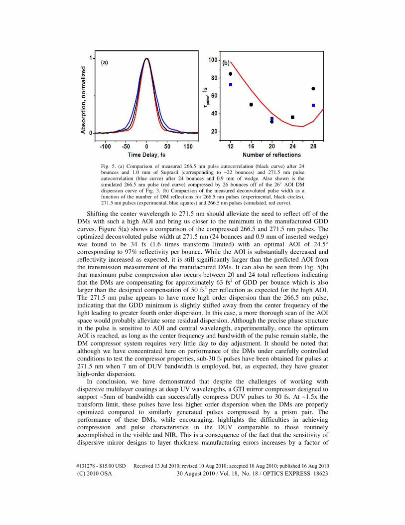
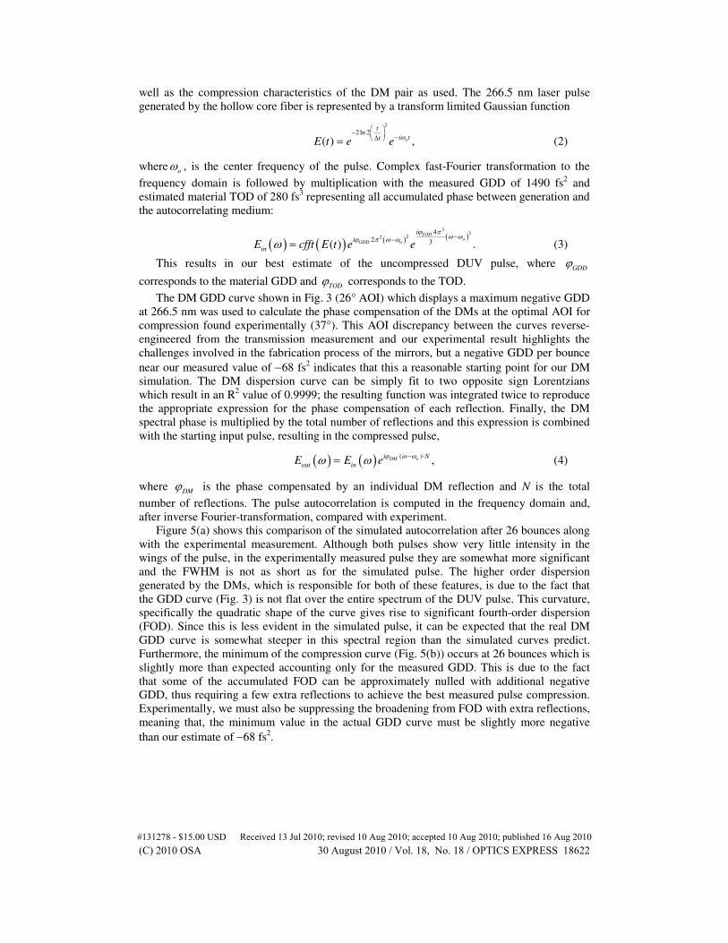
Fig. 5. (a) Comparison of measured 266.5 nm pulse autocorrelation (black curve) after 24
bounces and 1.0 mm of Suprasil (corresponding to ~22 bounces) and 271.5 nm pulse
autocorrelation (blue curve) after 24 bounces and 0.9 mm of wedge. Also shown is the
simulated 266.5 nm pulse (red curve) compressed by 26 bounces off of the 26° AOI DM
dispersion curve of Fig. 3. (b) Comparison of the measured deconvoluted pulse width as a
function of the number of DM reflections for 266.5 nm pulses (experimental, black circles),
271.5 nm pulses (experimental, blue squares) and 266.5 nm pulses (simulated, red curve).
Shifting the center wavelength to 271.5 nm should alleviate the need to reflect off of the
DMs with such a high AOI and bring us closer to the minimum in the manufactured GDD
curves. Figure 5(a) shows a comparison of the compressed 266.5 and 271.5 nm pulses. The
optimized deconvoluted pulse width at 271.5 nm (24 bounces and 0.9 mm of inserted wedge)
was found to be 34 fs (1.6 times transform limited) with an optimal AOI of 24.5°
corresponding to 97% reflectivity per bounce. While the AOI is substantially decreased and
reflectivity increased as expected, it is still significantly larger than the predicted AOI from
the transmission measurement of the manufactured DMs. It can also be seen from Fig. 5(b)
that maximum pulse compression also occurs between 20 and 24 total reflections indicating
that the DMs are compensating for approximately 63 fs2 of GDD per bounce which is also
larger than the designed compensation of 50 fs2 per reflection as expected for the high AOI.
The 271.5 nm pulse appears to have more high order dispersion than the 266.5 nm pulse,
indicating that the GDD minimum is slightly shifted away from the center frequency of the
light leading to greater fourth order dispersion. In this case, a more thorough scan of the AOI
space would probably alleviate some residual dispersion. Although the precise phase structure
in the pulse is sensitive to AOI and central wavelength, experimentally, once the optimum
AOI is reached, as long as the center frequency and bandwidth of the pulse remain stable, the
DM compressor system requires very little day to day adjustment. It should be noted that
although we have concentrated here on performance of the DMs under carefully controlled
conditions to test the compressor properties, sub-30 fs pulses have been obtained for pulses at
271.5 nm when 7 nm of DUV bandwidth is employed, but, as expected, they have greater
high-order dispersion.
In conclusion, we have demonstrated that despite the challenges of working with
dispersive multilayer coatings at deep UV wavelengths, a GTI mirror compressor designed to
support ~5nm of bandwidth can successfully compress DUV pulses to 30 fs. At ~1.5x the
transform limit, these pulses have less higher order dispersion when the DMs are properly
optimized compared to similarly generated pulses compressed by a prism pair. The
performance of these DMs, while encouraging, highlights the difficulties in achieving
compression and pulse characteristics in the DUV comparable to those routinely
accomplished in the visible and NIR. This is a consequence of the fact that the sensitivity of
dispersive mirror designs to layer thickness manufacturing errors increases by a factor of
#131278 - $15.00 USD Received 13 Jul 2010; revised 10 Aug 2010; accepted 10 Aug 2010; published 16 Aug 2010(C) 2010 OSA 30 August 2010 / Vol. 18, No. 18 / OPTICS EXPRESS 18623
approximately 3 in the DUV range as compared to the NIR. Although difficulties in the
manufacturing tolerances lead to a significant deviation away from the optimal working AOI,
even considering the increased losses with this prototype set of DUV DMs the ~45% overall
transmission efficiency puts this system on par with grating compressors. It is reasonable to
expect that revision in design based on the current characterization should allow for 80%
overall transmission with a broader GDD minimum. Furthermore, improved manufacturing
accuracy along with more complex designs based for instance on two-cavity GTI structures
might enable increasing the effective GDD compensation bandwidth by a factor of two. This
bandwidth would correspond to bandwidth-limited pulse durations closely approaching 10 fs.
Along with this, the absence of spatial/spectral dispersion problems associated with typical
compression methods and excellent transmitted wavefront, makes this an attractive new
method for DUV pulse compression. Although not thoroughly tested in this case, we see no
damage of the DM coating with the pulse powers used. The potential for high damage
thresholds offered by dielectric mirrors should allow for compression of the several µJs
needed for pump-probe and other applications without sustaining optical damage over time, as
is typical for prism methods in the DUV. With less residual dispersion, the improved temporal
characteristics of broad bandwidth DUV pulses will effectively widen the window of
observation available for time resolved studies, as well as provide suitable pulses for two-
dimensional and other non-linear spectroscopies [27,28].
Acknowledgements
The work at USC is supported by the National Science Foundation (NSF) under grant CHE-
0617060. C. Rivera was supported by a Ford Foundation Graduate Fellowship. We thank A.
Isemann for his help in starting the development of the DM system and C. Elles for assistance
in implementation as well as comments on this manuscript.
#131278 - $15.00 USD Received 13 Jul 2010; revised 10 Aug 2010; accepted 10 Aug 2010; published 16 Aug 2010(C) 2010 OSA 30 August 2010 / Vol. 18, No. 18 / OPTICS EXPRESS 18624