From Mirrors to Free-Space Optical Communication ...
18
future internet Review From Mirrors to Free-Space Optical Communication—Historical Aspects in Data Transmission Magdalena Garlinska 1, *, Agnieszka Pregowska 2 , Karol Masztalerz 3 and Magdalena Osial 4 1 National Center for Research and Development, 00 695 Warsaw, Poland 2 Institute of Fundamental Technological Research, Polish Academy of Sciences, 02 106 Warsaw, Poland; [email protected] 3 Faculty of Science and Engineering, University of Manchester, Manchester M15 6BH, UK; [email protected] 4 Faculty of Chemistry, University of Warsaw, 02 093 Warsaw, Poland; [email protected] * Correspondence: [email protected] Received: 11 October 2020; Accepted: 16 October 2020; Published: 22 October 2020 Abstract: Fast communication is of high importance. Recently, increased data demand and crowded radio frequency spectrum have become crucial issues. Free-Space Optical Communication (FSOC) has diametrically changed the way people exchange information. As an alternative to wire communication systems, it allows efficient voice, video, and data transmission using a medium like air. Due to its large bandwidth, FSOC can be used in various applications and has therefore become an important part of our everyday life. The main advantages of FSOC are a high speed, cost savings, compact structures, low power, energy efficiency, a maximal transfer capacity, and applicability. The rapid development of the high-speed connection technology allows one to reduce the repair downtime and gives the ability to quickly establish a backup network in an emergency. Unfortunately, FSOC is susceptible to disruption due to atmospheric conditions or direct sunlight. Here, we briefly discuss Free-Space Optical Communication from mirrors and optical telegraphs to modern wireless systems and outline the future development directions of optical communication. Keywords: Free-Space Optical communication; telecommunications; wireless communication; data transfer history; communication networks 1. Introduction People have always needed to communicate. Since the times when the only way to send a message with important information was to send a runner with it, mankind has made spectacular progress with data transfer. Within just a few centuries we got to the Information Age [1,2], in which globalization has become a reality. Nowadays, we cannot imagine living in a world without the Internet, which is the most popular source for acquiring knowledge and a medium of information exchange. Thanks to that we can send cross-continental messages within just a few seconds, navigate without physical on-paper maps, participate in distance learning, or do shopping via a smartphone, but that is not the end. In this amazing, electronic era we may explore the universe without any telescope or even consult with a medical doctor without leaving the house. The latter has become extremely important in light of the COVID-19 pandemic, especially during the lockdowns. Despite the spectacular progress in data transfer, people expect communication to be even faster. The more data we send or receive, the more efficient data transfer needs to be. Broadband Internet, i.e., high-speed public connectivity with a data transfer rate of at least 256 Kbit/s or more in one or both directions, is unavailable in many places and is becoming one of the most impactful problems in Future Internet 2020, 12, 179; doi:10.3390/fi12110179 www.mdpi.com/journal/futureinternet
-
Upload
khangminh22 -
Category
Documents
-
view
0 -
download
0
Transcript of From Mirrors to Free-Space Optical Communication ...

future internet
Review
From Mirrors to Free-Space OpticalCommunication—Historical Aspects inData Transmission
Magdalena Garlinska 1,*, Agnieszka Pregowska 2 , Karol Masztalerz 3 and Magdalena Osial 4
1 National Center for Research and Development, 00 695 Warsaw, Poland2 Institute of Fundamental Technological Research, Polish Academy of Sciences, 02 106 Warsaw, Poland;
[email protected] Faculty of Science and Engineering, University of Manchester, Manchester M15 6BH, UK;
[email protected] Faculty of Chemistry, University of Warsaw, 02 093 Warsaw, Poland; [email protected]* Correspondence: [email protected]
Received: 11 October 2020; Accepted: 16 October 2020; Published: 22 October 2020�����������������
Abstract: Fast communication is of high importance. Recently, increased data demand and crowdedradio frequency spectrum have become crucial issues. Free-Space Optical Communication (FSOC) hasdiametrically changed the way people exchange information. As an alternative to wire communicationsystems, it allows efficient voice, video, and data transmission using a medium like air. Due to itslarge bandwidth, FSOC can be used in various applications and has therefore become an importantpart of our everyday life. The main advantages of FSOC are a high speed, cost savings, compactstructures, low power, energy efficiency, a maximal transfer capacity, and applicability. The rapiddevelopment of the high-speed connection technology allows one to reduce the repair downtimeand gives the ability to quickly establish a backup network in an emergency. Unfortunately, FSOC issusceptible to disruption due to atmospheric conditions or direct sunlight. Here, we briefly discussFree-Space Optical Communication from mirrors and optical telegraphs to modern wireless systemsand outline the future development directions of optical communication.
Keywords: Free-Space Optical communication; telecommunications; wireless communication; datatransfer history; communication networks
1. Introduction
People have always needed to communicate. Since the times when the only way to send a messagewith important information was to send a runner with it, mankind has made spectacular progress withdata transfer. Within just a few centuries we got to the Information Age [1,2], in which globalizationhas become a reality. Nowadays, we cannot imagine living in a world without the Internet, which isthe most popular source for acquiring knowledge and a medium of information exchange. Thanksto that we can send cross-continental messages within just a few seconds, navigate without physicalon-paper maps, participate in distance learning, or do shopping via a smartphone, but that is not theend. In this amazing, electronic era we may explore the universe without any telescope or even consultwith a medical doctor without leaving the house. The latter has become extremely important in lightof the COVID-19 pandemic, especially during the lockdowns.
Despite the spectacular progress in data transfer, people expect communication to be even faster.The more data we send or receive, the more efficient data transfer needs to be. Broadband Internet,i.e., high-speed public connectivity with a data transfer rate of at least 256 Kbit/s or more in one orboth directions, is unavailable in many places and is becoming one of the most impactful problems in
Future Internet 2020, 12, 179; doi:10.3390/fi12110179 www.mdpi.com/journal/futureinternet

Future Internet 2020, 12, 179 2 of 18
the modern world [3]. In some conditions like dense urban development, where the installation ofoptical fiber lines generates significant costs [4–6], access to wireless Internet is very popular. Wirelesscommunication became a solution in places where the installation of fiber optic cables may be difficultor even impossible, like in areas across a road or behind water tanks, or in places of special architecturalimportance (e.g., historic city districts), or in national parks [7–9]. This type of data transfer hasadvantages such as a lower development cost, affordability of the network topology design andimplementation, and flexible maintenance of operating networks, a list of benefits not found in wiredcommunications. It has not been a long time since the inception of the first generation of wirelessnetworks, but today’s solutions have evolved a lot.
In the last century, a deep need for fast data transfer brought about microwave links, whichwere a mode of data transmission via electromagnetic radiation with wavelengths between 1 mm and1 m [10]. The basics of that technology were quite simple. When the microwave radiation reachesthe conducting material, like a copper wire, electron movement occurs, leading to the flow of electriccurrent. This technology was very popular for data transfer like radio, TV, cell phone communication,or even radars [11]. Regarding data transfer technologies, microwaves have a huge advantage, whichis the fact that they go directly through space, reaching their destination without bending their signal.They also do not reflect from the ionosphere, instead of passing through it, so they can be sent fromsatellites or local transmitters to any point on Earth. However, maintaining such links is becomingmore and more difficult due to the saturation of radio frequencies in large cities, their sensitivity tointerference, and the high risk of “leakage” of confidential data. Moreover, concerns about high licensefees for frequency bands and negative health effects started limiting their wide application. The last isdue to the physical effects of standing behind microwave radiation. These types of electromagneticwaves cause the vibration of different molecules like water, leading to their rotation, resulting infriction between them, which is followed by a temperature rise. Of course, that behavior of matterdepends on the frequency of the generated electromagnetic wave. For example, the microwave thatheats food operates at frequencies of a few GHz, while it has completely different frequencies whendata are transmitted. On the other hand, microwave data links use different frequencies, and theirinfluence on humans is far smaller. An example of this can be an insufficient bandwidth, affectingthe transmission of large packets of data such as high-resolution videos from teleconferences or themonitoring of closed-circuit television cameras.
The deep need for faster and more efficient data transfer gave us newer technologies withoutthe above-mentioned disadvantages. Optical Wireless Links, also called Free-Space Optics (FSO), aredevoid of many of the limitations possessed by microwave links [12,13]. FSO is a wireless opticalcommunication technology that uses the emission of optical radiation in an open space to transmit databetween two points without obstructing the line of sight between them [14]. Its basic ingredients aretransmitters, such as lasers or light-emitting diodes, and signal receivers, like photodetectors. Figure 1presents the schematic image of such communication between two points placed on two skyscrapers,while Figure 2 presents a connection between other places. FSO is a relatively new technology, butit shows a lot of promise, as modern-day systems enable short-range data transmission up to 8 kmwith a high capacity reaching up to 100 Gb/s [15]. Such systems are bidirectional due to the opticaltransceivers at both ends of the link. Both transceivers are connected to a data source, such as acomputer with a modem.
Communication systems in open space like air or the vacuum of outer space require the use ofappropriate sources of optical radiation. When selecting them, the following parameters should beconsidered: wavelength range, power of the emitted radiation, and compatibility of cooperation withelectronic modulating systems [16]. The wavelength range of the radiation in the FSO communicationsystem is primarily determined by the transmission properties of the medium in which the signalis transferred, like the atmosphere. This technology is very sensitive to the type of climate and theweather, including physical phenomena [17]. Another related issue is ensuring safety for both users of

Future Internet 2020, 12, 179 3 of 18
the FSO network and outsiders [18,19], as this limits both the power and frequency of light emitters inthe FSO.
Future Internet 2020, 12, x FOR PEER REVIEW 3 of 17
Figure 1. Schematic image of a Free-space Optical Communication link between two nearby skyscrapers, serving e.g., to create a LAN-to-LAN connection between A and B points.
Figure 2. Schematic image of Optical Communication links between different objects. Data transmitted on a narrow beam of laser light is marked in red.
Figure 1. Schematic image of a Free-space Optical Communication link between two nearby skyscrapers,serving e.g., to create a LAN-to-LAN connection between A and B points.
Future Internet 2020, 12, x FOR PEER REVIEW 3 of 17
Figure 1. Schematic image of a Free-space Optical Communication link between two nearby skyscrapers, serving e.g., to create a LAN-to-LAN connection between A and B points.
Figure 2. Schematic image of Optical Communication links between different objects. Data transmitted on a narrow beam of laser light is marked in red.
Figure 2. Schematic image of Optical Communication links between different objects. Data transmittedon a narrow beam of laser light is marked in red.

Future Internet 2020, 12, 179 4 of 18
2. Historical Background
The first long-distance messages were sent via a runner to warn of an invasion of some otherdanger, but that was too often too slow. To increase the speed of physical data transfer, people startedto send messages by air, via pigeons and other birds. In some tribes in Africa, messages were sent byspecial instruments, called talking drums, while in North America some Indian tribes sent messagesusing smoke signals. This allowed for nearly real-time communication over medium distances. Evenin the late 16th century ships used that way of signaling by employing coded flags. These systemswere used in limited geographic areas, but they evolved over the centuries and developed into thetechnology that we know today.
The beginning of optical communication dates back to antiquity [20,21]. The past civilizationsused mirrors, fire beacons, or smoke signals for data transfer, in very low volumes [22]. In AncientGreece, torch-based signaling systems were made by Cleoxenus, Democleitus, and Polybius [23].In 1672, the first acoustic telephone transferring a signal over a wire was demonstrated by RobertHooke. The real breakthrough in the transmission of information took place in 1792 when ClaudeChappe presented the idea of transmitting mechanically coded messages over long distances [24]. Forthis purpose, a network of special semaphores was developed. The first practical electric telegraphwas invented by the Russian Baron Schilling in 1823 [25]. That invention was in use during the FrenchRevolution, connecting the French Army and Lille headquarters in Paris. In this way, the first wirelesssolar telegraph (heliograph) was invented. Figure 3 shows a scheme of the heliograph. The firstapplication of Chappe’s optical telegraph took place between Paris and Lille in July 1794, with thecities being located about 200 km apart. The following century changed telecommunication, bringingabout the discovery of electromagnetism by Hans Christian Oersted in 1819 [26].
Future Internet 2020, 12, x FOR PEER REVIEW 5 of 17
Figure 3. A scheme of a heliograph.
The invention of artificial electric light sources made it possible to build simple optical telecommunication systems, such as: flashing signal lamps for ship-to-ship communication, ship-to-shore communication, car direction indicators, etc. [31]. These systems had a low efficiency of information transmission. In 1954, in fact, masers, microwave amplification by stimulated emission of radiation, was developed [32]. Four years later, the same team behind masers introduced lasers (Light Amplification by Stimulated Emission of Radiation) as an efficient source of light [33], and these inventions radically increased the efficiency of data transmission [34].
In the mid-1960s, NASA began experimenting with the use of a laser as a communication tool between Earth and space [35]. The first articles on FSO were published in Berlin in 1968 by Ph. D. Erhard Kube, considered to be the father of FSO [36]. The first commercial systems with a capacity of 100 kb/s to 34 Mb/s were published in 1985. In 1999, lines with a capacity of 100–155 Mb/s were developed, and a little later 622 Mb/s data rates were obtained. Currently, capacities of up to 100 Gb/s are achieved [37,38]. In the 90s, the wireless revolution began [39].
3. FSO Communication System Constructions
The general idea of Free-Space Optics relies on the transmission of invisible, eye-safe light beams. They are transmitted by a laser with light focused onto a highly sensitive photon detector, which serves as a receiver, equipped with a telescopic lens. In fact, the FSO operation is somewhat similar to an infrared TV remote controller. Free-Space Optical links have quite a simple construction, typically consisting of two identical heads enabling duplex data transmission, as shown in Figure 4. These heads are connected via interfaces directly to computers or with a telecommunications network. Physically, these connections are made by fiber optic cables (single and multimode) or Bayonet Neill–Concelman British Naval Connector/Spanning-Tree Protocol (BNC/STP) coaxial cables. BNC connects the computer with the coaxial cable. Generally, BNC is a commonly used plug and socket for audio, video, and networking applications that provides a tight connection.
Figure 3. A scheme of a heliograph.
Some years later, the optical telegraph network expanded throughout Europe [27]. The lightserved as a medium by which it was possible to make encoded signals visible so that they could beintercepted by relay stations. In 1835, the single-wire telegraph system was developed, and electricalcommunications throughout the world started. Within just two years, Samuel Morse demonstrated a

Future Internet 2020, 12, 179 5 of 18
device sending short and long electric pulses as dots and dashes. The transmission of Morse-codedsignals was fast and reliable, and, in fact, variances of this system are still in use [28].
During the Second World War, the Germans used the optical Morse code transmitter Blinkgerät,which allowed for communication over distances of about 4 km during the day and 8 km at night [29].This was possible thanks to the use of red optical filters, which made communications nearlyundetectable. The modern-day Air Traffic Control towers have special devices intended to emitmulticolor light in case of radio system failures, and all the pilots know the special procedures tonavigate using those lights. The next step on the path to modern communication systems was AlexanderGraham Bell’s invention [30], which allowed for voice transmission over long distances. In 1880, heconstructed a system for light communication called a photophone. To transfer the conversations ata distance, he used sunlight reflected from a tiny mirror, vibrating under the influence of the voice.The speech was passed through the atmosphere to the receiver using light. There, the modulated solarradiation was converted into an electrical signal in a selenium photocell that was connected to theheadphones. Even though this system was never widely used, it was a good proof of concept for theFSO communication systems.
The invention of artificial electric light sources made it possible to build simple opticaltelecommunication systems, such as: flashing signal lamps for ship-to-ship communication,ship-to-shore communication, car direction indicators, etc. [31]. These systems had a low efficiency ofinformation transmission. In 1954, in fact, masers, microwave amplification by stimulated emissionof radiation, was developed [32]. Four years later, the same team behind masers introduced lasers(Light Amplification by Stimulated Emission of Radiation) as an efficient source of light [33], and theseinventions radically increased the efficiency of data transmission [34].
In the mid-1960s, NASA began experimenting with the use of a laser as a communication toolbetween Earth and space [35]. The first articles on FSO were published in Berlin in 1968 by Ph. D.Erhard Kube, considered to be the father of FSO [36]. The first commercial systems with a capacityof 100 kb/s to 34 Mb/s were published in 1985. In 1999, lines with a capacity of 100–155 Mb/s weredeveloped, and a little later 622 Mb/s data rates were obtained. Currently, capacities of up to 100 Gb/sare achieved [37,38]. In the 90s, the wireless revolution began [39].
3. FSO Communication System Constructions
The general idea of Free-Space Optics relies on the transmission of invisible, eye-safe light beams.They are transmitted by a laser with light focused onto a highly sensitive photon detector, which servesas a receiver, equipped with a telescopic lens. In fact, the FSO operation is somewhat similar to aninfrared TV remote controller. Free-Space Optical links have quite a simple construction, typicallyconsisting of two identical heads enabling duplex data transmission, as shown in Figure 4. These headsare connected via interfaces directly to computers or with a telecommunications network. Physically,these connections are made by fiber optic cables (single and multimode) or Bayonet Neill–ConcelmanBritish Naval Connector/Spanning-Tree Protocol (BNC/STP) coaxial cables. BNC connects the computerwith the coaxial cable. Generally, BNC is a commonly used plug and socket for audio, video, andnetworking applications that provides a tight connection.
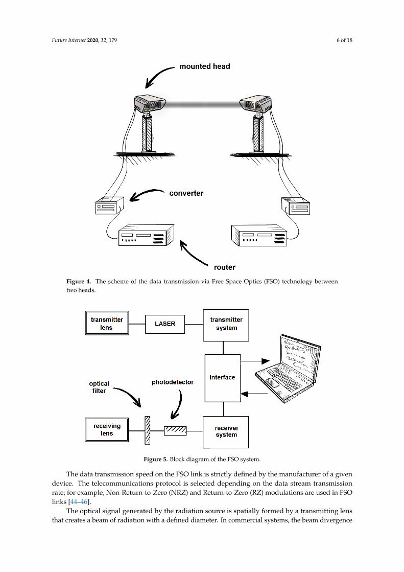
The block diagram of the transceiver head of a typical FSO link is presented in Figure 5. It includestwo main blocks: a transmitter and a receiver of the optical radiation. The source of the optical radiationmay be a light-emitting diode, a semiconductor laser, or several lasers [40]. LEDs and semiconductorlasers are used in wireless optical links for short distances (e.g., inside buildings) [41]. On the otherhand, FSO links for longer distances mainly use vertical-cavity surface-emitting lasers [42].
Lasers provide more power and faster transmission speeds than LEDs [43]. The advantage ofsurface radiating lasers, compared to classic edge lasers, is the symmetrical spatial characteristic ofthe radiation.
Future Internet 2020, 12, 179 6 of 18Future Internet 2020, 12, x FOR PEER REVIEW 6 of 17
Figure 4. The scheme of the data transmission via Free Space Optics (FSO) technology between two heads.
The block diagram of the transceiver head of a typical FSO link is presented in Figure 5. It includes two main blocks: a transmitter and a receiver of the optical radiation. The source of the optical radiation may be a light-emitting diode, a semiconductor laser, or several lasers [40]. LEDs and semiconductor lasers are used in wireless optical links for short distances (e.g., inside buildings) [41]. On the other hand, FSO links for longer distances mainly use vertical-cavity surface-emitting lasers [42].
Figure 5. Block diagram of the FSO system.
Figure 4. The scheme of the data transmission via Free Space Optics (FSO) technology betweentwo heads.
Future Internet 2020, 12, x FOR PEER REVIEW 6 of 17
Figure 4. The scheme of the data transmission via Free Space Optics (FSO) technology between two heads.
The block diagram of the transceiver head of a typical FSO link is presented in Figure 5. It includes two main blocks: a transmitter and a receiver of the optical radiation. The source of the optical radiation may be a light-emitting diode, a semiconductor laser, or several lasers [40]. LEDs and semiconductor lasers are used in wireless optical links for short distances (e.g., inside buildings) [41]. On the other hand, FSO links for longer distances mainly use vertical-cavity surface-emitting lasers [42].
Figure 5. Block diagram of the FSO system. Figure 5. Block diagram of the FSO system.
The data transmission speed on the FSO link is strictly defined by the manufacturer of a givendevice. The telecommunications protocol is selected depending on the data stream transmissionrate; for example, Non-Return-to-Zero (NRZ) and Return-to-Zero (RZ) modulations are used in FSOlinks [44–46].
The optical signal generated by the radiation source is spatially formed by a transmitting lensthat creates a beam of radiation with a defined diameter. In commercial systems, the beam divergence
Future Internet 2020, 12, 179 7 of 18
angle is between 2 and 10 mrad. Beams with a small divergence angle can only be used in FSO systemsequipped with beam targeting and stabilization systems. In simpler solutions, beams with a greaterdivergence angle are used. This type of solution facilitates the adjustment of the system and enablesoperation during vibrations of the supporting structure and when the refraction of the atmosphere ischanging (e.g., due to a variable temperature or air density). A large advantage of this simplicity isalso the reduction of costs of the FSO setup and maintenance. However, the divergence of the beammeans that the beam spreads out quicker and hence loses power at a distance, meaning that FSOcommunication using such a beam is limited in range.
The existence of beam divergence causes the diameter of the optical radiation beam to increasewith an increasing distance from the source. The power density distribution, in the plane that isperpendicular to the radiation propagation direction, is usually described by the Gaussian distribution.This beam creates an illuminated area in the receiver plane, with an area generally much largerthan the effective receiving area. This results in a radiation power loss resulting from the ratio ofthese surfaces. The atmosphere causes an additional power loss because it absorbs and scatters thetransmitted radiation.
The power of the radiation reaching the receiver can be determined from the following formula [47]:
Prec = PtransD2
rec
(θR)2 τ (1)
where Ptrans is the radiation power emitted by the transmitter, Drec is the diameter of the receiver optics,R is the distance between the transmitter and receiver, Θ is the beam divergence angle, and τ is theatmospheric transmission coefficient.
For the FSO link to operate with an acceptable bit error rate, the Prec power must be higher thanthe noise. Having the defined minimum received power Precmin, the link range can be determined fromthe Formula (1):
R =
√Ptrans
Precmin
Drec
θ
√τ. (2)
Thus, a formed and modulated optical signal reaches the opposite optical radiation receiver,which consists of a receiving lens, an optical filter, a photodiode with a power supply and coolingsystem, a low-noise preamplifier, and a signal processing system.
The optical system is used to focus the radiation onto the surface of the detector (avalanche orpin photodiode). For larger surfaces of the optical system, an optical signal with a higher intensity isobtained. The use of optical systems with larger surfaces is advantageous due to the possibility ofusing photodiodes with smaller active surfaces and due to the mitigation of the effect of photon fluxfluctuation (scintillation). With a larger aperture of the receiving system, “aperture averaging” of thephoton flux fluctuation also takes place. With a sufficiently large aperture, the fluctuating beam iswithin the lens surface, so the fluctuations will be averaged according to:
Drec ≈√
Rλ. (3)
Formula (3) shows that the diameter of the lens should match the planned range of the link on agiven wavelength. Thus, for a link with a range of 1 km, λ = 10 µm, the diameter of the receiving lensshould be less than 10 cm. The use of a receiving lens with a larger diameter will increase the weight ofthe FSO head and its cost, while not bringing any large benefits to the data transmission rate.
In addition to the useful signal, the background radiation reaches the receiver of the FSOsystem, causing an increase in noise. As a consequence, the ratio of the signal power to noise powerdecreases [48]. The power of the background radiation reaching the optical system of the receiverdepends on the field of view of the lens and its active surface (aperture). To improve the ratio ofthe signal power to the noise power, the receiver is equipped with optical filters, which narrow itsspectral range down to the ∆λ band covering the transmitted signal band. Another technique used

Future Internet 2020, 12, 179 8 of 18
for the reduction of noise is the direct isolation of noise sources. For example, the FSO receiver setup in the shade will be protected from noise-inducing sunlight, which is especially prominent in thenear-infrared band.
In the signal processing circuit, the received signal is amplified, demodulated, and then forwardedto the interface.
FSO transceivers are placed on masts, buildings, and other structural elements, so they aresusceptible to strong gusts of wind. To avoid a break in communication, multibeam systems, orsystems for directing and stabilizing the position of the laser beam (so-called Automatic Tracking(AT) systems) are used [49]. Using an AT system, the FSO head changes its position to search for thestrongest possible signal from the transmitter. For this purpose, photoreceivers with position-sensingdiode detectors and other special articulations are used to enable the positioning of the head in threeplanes. This is of particular importance in portable FSO systems [50].
In FSO links, systems for heating the transmitter/receiver optics can be used [51]. The use of thesesolutions allows the devices to operate in a wider temperature range, e.g., from −40 ◦C to 70 ◦C, andprevents the frosting of the optical systems or the dewing of the lenses.
In Table 1, the parameters of the FSO systems that are commercially available are presented.
Table 1. Summary of the basic commercial FSO system parameters [52–55].
FSO system FlightStrata 52E CableFree G2000 SONAbeam10G-E+
Koruza Bridge10 Gbps
Description
Multiple BeamSystem with Auto
Tracking—full duplex
Multiple Beam System withAutomatic Transmit Power
Control (ATPC)—full-duplex
Multiple BeamSystem—full duplex
Single beamunit—full duplex
Bit Rate Up to 155 Mbps Up to 1.5 Gbps Up to 10 Gbps Up to 10 Gbps
Distance Up to 5600 m Up to 2000 m Up to 1000 m <150 m,
Optical Transmitter VCSEL VCSEL InGaAsP LaserDiode
SC SFP WDM Bi-Dimodule with DDM
Wavelength 850 nm 780 nm 1550 nm 1270 nm/1310 nm
Optical TransmitPower −20 dBm +19.0 dBm +26 dBm +0.5 dBm
Optical Receiver Si APD APD APD SC SFP WDM Bi-Dimodule with DDM
Unit Weight 11.1 kg 9 kg 8 kg 2 kg
OperatingTemperature −25 ◦C to 60 ◦C −20 ◦C to 60 ◦C −40 ◦C to 50 ◦C −40 ◦C to 60 ◦C
PowerConsumption Max. 20 W 45 W 40 W 6 W
In the receiving circuits for some of the FSO links, special solutions may be used to regeneratethe shape of the impulse waveforms. This regeneration restores the signal to its original power(Reamplifing), and restores the shape of the impulse (Reshaping) and the time relations (Retiming) byresynchronizing the local clock (resynchronization) [56].
4. Laser Wavelengths Versus FSO Links
A huge effort has been made to understand the physical phenomena related to the propagation ofoptical radiation in the Earth’s atmosphere [57–75]. Most of the conducted research focuses on thephenomena related to the absorption and scattering of radiation by atoms and molecules that makeup the atmosphere, as well as by natural and artificial pollutants: fog, rain, smoke, pollen, and dust.Indeed, the presence of rain and snow can influence the FSO links [76], while fog and water vapordroplets significantly lower data transmission efficiency, especially in the tropics [77]. The presenceof water vapor molecules in the air contributes to the absorption of some light particles (photons)

Future Internet 2020, 12, 179 9 of 18
within the light beam due to absorption, refraction, and scattering. This causes an overall loss in powerdensity in the received signals. This is similar to the impact that rain-fading has on Radio Frequency(RF) wireless systems, which contributes to signal attenuation. FSO may also be temporarily blockedby moving objects such as flying birds, Unmanned Aerial Vehicles (UAVs), or aircraft. Permanentblocking may also be caused by stationary objects such as trees or tall buildings [78].
Since the physics of the atmosphere cannot be changed, the wavelengths of the lasers used in FSOare selected to operate in so-called “atmospheric transmission windows”. In Figure 6, an exampleof the characteristics of the atmosphere transmission coefficient for a distance of 1 km is presented.The spectral ranges in which the atmosphere has relatively low absorption of radiation are noticeable.Commercial systems mainly use spectral ranges corresponding to transmission windows of around0.8 µm and 1.5 µm.
Future Internet 2020, 12, x FOR PEER REVIEW 9 of 17
phenomena related to the absorption and scattering of radiation by atoms and molecules that make up the atmosphere, as well as by natural and artificial pollutants: fog, rain, smoke, pollen, and dust. Indeed, the presence of rain and snow can influence the FSO links [76], while fog and water vapor droplets significantly lower data transmission efficiency, especially in the tropics [77]. The presence of water vapor molecules in the air contributes to the absorption of some light particles (photons) within the light beam due to absorption, refraction, and scattering. This causes an overall loss in power density in the received signals. This is similar to the impact that rain-fading has on Radio Frequency (RF) wireless systems, which contributes to signal attenuation. FSO may also be temporarily blocked by moving objects such as flying birds, Unmanned Aerial Vehicles (UAVs), or aircraft. Permanent blocking may also be caused by stationary objects such as trees or tall buildings [78].
Since the physics of the atmosphere cannot be changed, the wavelengths of the lasers used in FSO are selected to operate in so-called “atmospheric transmission windows”. In Figure 6, an example of the characteristics of the atmosphere transmission coefficient for a distance of 1 km is presented. The spectral ranges in which the atmosphere has relatively low absorption of radiation are noticeable. Commercial systems mainly use spectral ranges corresponding to transmission windows of around 0.8 µm and 1.5 µm.
The wavelength of the laser radiation used in FSO links depends on the transmission properties of the atmosphere, particularly fog, as well as the availability and parameters of the lasers [79]. The attenuation is classified into three groups: Rayleigh scattering (molecule scattering, when the molecule is smaller than the light wavelength), Mie scattering (aerosol scattering, when the size of the molecule is comparable to the wavelength), and nonselective scattering (geometric scattering, when the size of the molecule is larger than wavelength size) [80]. Since some attenuation processes strongly depend on the wavelength (Rayleigh scattering from air molecules), the proposed choice of wavelength is highly important. It is known that the attenuation is much greater for shorter wavelengths in the case of scattering. In fact, it varies inversely to the fourth power of the wavelength [81]. Fog causes the Mie scattering, larger particles of snow cause the geometric scattering (having similar effects to the Rayleigh scattering), while rainfall contributes to nonselective scattering [82]. Other phenomena that may affect transmission efficiency are smoke [83], sandstorms [84], and clouds [85].
Figure 6. Atmospheric transmission spectrum up to 14 µm showing the wavelength regions where particular molecules absorb the electromagnetic wave.
In addition to physical assessments, other media should also be considered when selecting the type of laser [86]. For a wavelength range of 780–880 nm, cost-effective and reliable lasers with very good parameters as well as detectors, which are used in consumer devices, are easily available. Silicon pin and avalanche photodiodes, LEDs, semiconductor laser diodes, and Vertical-Cavity Surface-Emitting Lasers (VCSEL) are used to work at these wavelengths [87]. Within a wavelength range of 1520–1600 nm, both sources and detectors of optical radiation are also readily available. In this band,
Figure 6. Atmospheric transmission spectrum up to 14 µm showing the wavelength regions whereparticular molecules absorb the electromagnetic wave.
The wavelength of the laser radiation used in FSO links depends on the transmission propertiesof the atmosphere, particularly fog, as well as the availability and parameters of the lasers [79].The attenuation is classified into three groups: Rayleigh scattering (molecule scattering, when themolecule is smaller than the light wavelength), Mie scattering (aerosol scattering, when the size of themolecule is comparable to the wavelength), and nonselective scattering (geometric scattering, whenthe size of the molecule is larger than wavelength size) [80]. Since some attenuation processes stronglydepend on the wavelength (Rayleigh scattering from air molecules), the proposed choice of wavelengthis highly important. It is known that the attenuation is much greater for shorter wavelengths in thecase of scattering. In fact, it varies inversely to the fourth power of the wavelength [81]. Fog causes theMie scattering, larger particles of snow cause the geometric scattering (having similar effects to theRayleigh scattering), while rainfall contributes to nonselective scattering [82]. Other phenomena thatmay affect transmission efficiency are smoke [83], sandstorms [84], and clouds [85].
In addition to physical assessments, other media should also be considered when selecting the typeof laser [86]. For a wavelength range of 780–880 nm, cost-effective and reliable lasers with very goodparameters as well as detectors, which are used in consumer devices, are easily available. Silicon pinand avalanche photodiodes, LEDs, semiconductor laser diodes, and Vertical-Cavity Surface-EmittingLasers (VCSEL) are used to work at these wavelengths [87]. Within a wavelength range of 1520–1600 nm,both sources and detectors of optical radiation are also readily available. In this band, semiconductorlasers made of Indium Gallium Arsenide (InGaAs) are used. Although 1550-nm lasers were developedfor fiber optic connectivity, they have also found application in FSO links. For the detection of optical
Future Internet 2020, 12, 179 10 of 18
radiation in this wavelength range, PIN (P-type, Intrinsic, N-type semiconductor) and AvalanchePhotodiode (APD) photodiodes are made of InGaAs are mainly used [88]. Currently, research is beingconducted on the use of Quantum Cascade Lasers (QCLs) [89,90] in optical communication systemsin the range of 10–12 µm [91]. Currently, there are no commercially available links operating at thiswavelength range.
5. FSO and Safety Concerns for Humans
One of the most important issues relating to the use of FSO links is ensuring an appropriate levelof eye safety. This is especially important not only during the link alignment, when technicians usetelescopes or binoculars to look at the incoming beam but also during the ordinary operation of theFSO when unauthorized people could cross the laser path by accident. The definition of radiation thatis safe for humans is included in the international standard IEC 60825 [92]. Accordingly, the intensityof laser radiation to which people may be exposed without suffering any harmful effects determinesthe time of the maximum permissible exposure. It depends on the wavelength of the radiation, thepulse duration, the type of tissue exposed to laser radiation, and the dimensions of the image on theretina (for wavelengths from 400 nm to 1400 nm). The main eye hazard from laser radiation is damageto the eye’s retina [93]. Burns or damages caused by the laser may lead to permanent or temporaryloss of vision, depending on the exposure time. Radiation in the wavelength range above 1400 nm,as well as below 400 nm, is strongly absorbed by tissues, and therefore it does not penetrate the eyeand does not damage the retina. The introduced regulations concerning the classification of devicesequipped with a laser are based on criteria of the wavelength and power density of the incident laserradiation. FSO links should meet the requirements of class 1, and with optical devices, they shouldmeet those of class 1M.
Conducted research shows that, for FSO systems operating with wavelengths of 1550 nm and800 nm, the permissible power densities are 100 mW/cm2 and 2.0 mW/cm2, respectively [94]. Thus,for a transmitting lens with a diameter of 100 mm, the laser power can be increased to 160 mW forλ = 800 nm and up to 8 W for λ = 1550 nm. Thus, at a wavelength of 1550 nm, radiation can be emittedwith 50 times more power than in the case of radiation with a wavelength of 800 nm. Due to eye safety,it is reasonable to use radiation sources in the far-infrared range in FSO systems. Naturally, visiblelight or ultraviolet links are not employed, as they carry a higher energy per photon, making themmore dangerous. An additional issue to consider with visible-light-based systems is the fact that, dueto the scattering of light from laser beams, beams could be visible to naked eyes during nighttime.
6. FSO Advantages and Disadvantages
Free-Space Optical Communication is the answer to the worldwide demand for broadbandcommunications offering flexible network connections [95]. FSO systems are more secure than RF orother wireless-based transmission systems since it is impossible to detect laser beams with spectrumanalyzers or RF meters. It is difficult or even impossible to intercept the data transmission, as laserbeams are narrow and invisible to the naked eye. Moreover, the information can be transmitted overan encrypted connection, which contributes significantly to increasing the security level [96]. FSObridges the gaps in existing high-data-rate communication networks. Its ease of installation andhigh throughput with relatively low investment outlays make it a rapidly deployable mobile wirelesscommunication infrastructure [78]. Freedom of licensing (no licenses are required) means that there areno administrative difficulties related to their installation [97]. Another FSO advantage includes a verylow bit error rate, while extremely narrow laser beams ensure that there is almost no practical limit tothe number of separate FSO links that can be installed in a given location, which is in direct contrast toomnidirectional RF links. Moreover, due to the narrow beam and easy supervision of interference inthe beam, FSO links ensure high resistance to eavesdropping. The transmitted data are inaccessible tounauthorized system recipients, and the active methods of notification about any attempt to join thelink, supported by appropriate transmission protocols, ensure a relatively high degree of transmitted
Future Internet 2020, 12, 179 11 of 18
data confidentiality [98]. FSO is also, by definition, a low-latency technology [99]. In comparison tofiber optics, there is about a 40 percent reduction in latency, as the speed of light in air is about 40percent higher than in a fiber cable. Moreover, the direct Line of Sight path between two endpoints isshorter than any curved path taken by a fiber-optic cable.
FSO links are comparable to radio ones in terms of the transmission medium; however, theyexceed them in terms of bandwidth, operating costs, and installation speed. They provide ranges of upto several kilometers [100]. Hence, they can be used in crises and military communication systems. Itshould also be emphasized that the return on investment costs is very fast in comparison to the cost ofbuilding a fiber-optic line connecting buildings that are separated by, e.g., 1000 m.
As was mentioned in the “Laser wavelengths used in the FSO links” section, the main phenomenathat disrupt FSO communication are rain, which absorbs radiation, and smoke/haze/fog-inducedMie scattering. Disruptions are also caused by Rayleigh scattering and photon absorption, snow,scintillations (fluctuations in the refractive index), and industrial pollution (smog and particulatematter in 2.5- and 10-micrometer dimensions (PM2.5/PM10)) [20]. High concentrations of carbondioxide in the air can also cause the absorption of transmitted signals, which is particularly significantfor near-infrared links and less so for SWIR band links [95]. Additionally, even heavy rain and snowenable data transmission, even though they weaken the signal reaching the receiver and lead to anincrease in the bit error rate. However, the most dangerous weather phenomenon that can break theconnection is fog [82].
One of the factors that may make the employment of the FSO system impractical occurs when thetransceiver heads are oriented east-west, due to the possibility of transmission interference caused bydirect solar radiation, especially during sunset/sunrise [101,102]. This applies in particular to 850-nmsystems. With a different link setting and the use of nontransparent covers, sunlight does not have asignificant effect on the operation of the system.
FSO links have a wide range of applications in different fields, such as connections between BaseTransceiver Stations (BTS) of mobile telephony, Local Area Network (LAN-LAN) connections betweenoffice buildings with Fast Ethernet or Gigabit Ethernet speeds [103], confidential communicationnetworks (i.e., financial, medical, and military networks [104]), temporary connections (e.g., HD imagetransmission from cameras, large screen connection, Internet access, e.g., during the Olympic Games).Due to its stability and flexibility, FSO is a good solution for building-to-building connectivity. Its usecan help solve the last mile problem for connections at fiber speeds [105,106]. FSO enables the quickrebuilding of connections after damage and disasters. Moreover, it can serve as an additional backupfor fiber-optic networks, and it can complement other wireless technologies.
FSO systems also have their drawbacks and limitations. As was already mentioned, the spreadingloss is high, and there is atmospheric loss resulting from water and carbon dioxide molecules. The powerconsumption is higher than for typical RF links. The transmitter and receiver should be in the lineof sight, so there may be significant restrictions on the location of their installation because thetransmitter could get blocked due to trees, buildings, etc. Furthermore, birds and scintillation causebeam interruptions. High-powered lasers may not be safe for bystanders, and the installation must beperformed by qualified personnel. The costs of the system and its installation are also a big limitation,as the cost of equipment could be between $3000 and $10,000. It is also worth mentioning that thelaser diodes used in FSO transceivers have a limited life before they fail, typically about 7–8 years, incomparison to radio links, which can last much longer.
7. The Communication Networks in the Future
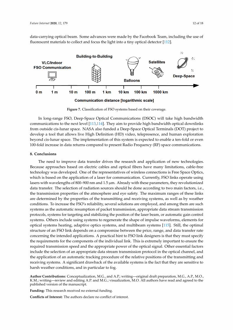
The crucial issue in Free-Space Communication is to expand the maximum usable distance betweentransceivers [107]. In Figure 7, FSO types are presented according to their maximum operational range.In the nearest future, the communication network infrastructure must adjust to the fifth-generation(5G) [108,109] and the sixth-generation (6G) standards [110,111]. This is connected with the designingand implementation of high-speed detectors. The main difficulty is the effective collection of the
Future Internet 2020, 12, 179 12 of 18
data-carrying optical beam. Some advances were made by the Facebook Team, including the use offluorescent materials to collect and focus the light into a tiny optical detector [112].
Future Internet 2020, 12, x FOR PEER REVIEW 12 of 17
effective collection of the data-carrying optical beam. Some advances were made by the Facebook Team, including the use of fluorescent materials to collect and focus the light into a tiny optical detector [112].
Figure 7. Classification of FSO systems based on their coverage.
In long-range FSO, Deep-Space Optical Communications (DSOC) will take high bandwidth communications to the next level [113,114]. They aim to provide high bandwidth optical downlinks from outside cis-lunar space. NASA also funded a Deep-Space Optical Terminals (DOT) project to develop a tool that allows live High Definition (HD) video, telepresence, and human exploration beyond cis-lunar space. The implementation of this system is expected to enable a ten-fold or even 100-fold increase in data returns compared to present Radio Frequency (RF) space communications.
8. Conclusions
The need to improve data transfer drives the research and application of new technologies. Because approaches based on electric cables and optical fibers have many limitations, cable-free technology was developed. One of the representatives of wireless connections is Free Space Optics, which is based on the application of a laser for communication. Currently, FSO links operate using lasers with wavelengths of 800–900 nm and 1.5 µm. Already with these parameters, they revolutionized data transfer. The selection of radiation sources should be done according to two main factors, i.e., the transmission properties of the atmosphere and eye safety. The maximum ranges of these links are determined by the properties of the transmitting and receiving systems, as well as by weather conditions. To increase the FSO’s reliability, several solutions are employed, and among them are such systems as the automatic resumption of packet transmission, appropriate data stream transmission protocols, systems for targeting and stabilizing the position of the laser beam, or automatic gain control systems. Others include using systems to regenerate the shape of impulse waveforms, elements for optical systems heating, adaptive optics systems, and multibeam systems [115]. Still, the optimal structure of an FSO link depends on a compromise between the price, range, and data transfer rate concerning the intended applications. A practical hint to FSO link designers is that they must specify the requirements for the components of the individual link. This is extremely important to ensure the required transmission speed and the appropriate power of the optical signal. Other essential factors include the selection of an appropriate data stream transmission protocol in the optical channel, and the application of an automatic tracking procedure of the relative positions of the transmitting and receiving systems. A significant drawback of the available systems is the fact that they are sensitive to harsh weather conditions, and in particular to fog.
Author Contributions: Conceptualization, M.G., and A.P.; writing—original draft preparation, M.G., A.P., M.O., K.M.; writing—review and editing A.P. and M.G.; visualization, M.O. All authors have read and agreed to the published version of the manuscript.
Funding: This research received no external funding.
Conflicts of Interest: The authors declare no conflict of interest.
Figure 7. Classification of FSO systems based on their coverage.
In long-range FSO, Deep-Space Optical Communications (DSOC) will take high bandwidthcommunications to the next level [113,114]. They aim to provide high bandwidth optical downlinksfrom outside cis-lunar space. NASA also funded a Deep-Space Optical Terminals (DOT) project todevelop a tool that allows live High Definition (HD) video, telepresence, and human explorationbeyond cis-lunar space. The implementation of this system is expected to enable a ten-fold or even100-fold increase in data returns compared to present Radio Frequency (RF) space communications.
8. Conclusions
The need to improve data transfer drives the research and application of new technologies.Because approaches based on electric cables and optical fibers have many limitations, cable-freetechnology was developed. One of the representatives of wireless connections is Free Space Optics,which is based on the application of a laser for communication. Currently, FSO links operate usinglasers with wavelengths of 800–900 nm and 1.5 µm. Already with these parameters, they revolutionizeddata transfer. The selection of radiation sources should be done according to two main factors, i.e.,the transmission properties of the atmosphere and eye safety. The maximum ranges of these linksare determined by the properties of the transmitting and receiving systems, as well as by weatherconditions. To increase the FSO’s reliability, several solutions are employed, and among them are suchsystems as the automatic resumption of packet transmission, appropriate data stream transmissionprotocols, systems for targeting and stabilizing the position of the laser beam, or automatic gain controlsystems. Others include using systems to regenerate the shape of impulse waveforms, elements foroptical systems heating, adaptive optics systems, and multibeam systems [115]. Still, the optimalstructure of an FSO link depends on a compromise between the price, range, and data transfer rateconcerning the intended applications. A practical hint to FSO link designers is that they must specifythe requirements for the components of the individual link. This is extremely important to ensure therequired transmission speed and the appropriate power of the optical signal. Other essential factorsinclude the selection of an appropriate data stream transmission protocol in the optical channel, andthe application of an automatic tracking procedure of the relative positions of the transmitting andreceiving systems. A significant drawback of the available systems is the fact that they are sensitive toharsh weather conditions, and in particular to fog.
Author Contributions: Conceptualization, M.G., and A.P.; writing—original draft preparation, M.G., A.P., M.O.,K.M.; writing—review and editing A.P. and M.G.; visualization, M.O. All authors have read and agreed to thepublished version of the manuscript.
Funding: This research received no external funding.
Conflicts of Interest: The authors declare no conflict of interest.

Future Internet 2020, 12, 179 13 of 18
References
1. Wang, B.; Wu, C. Safety informatics as a new, promising and sustainable area of safety science in theinformation age. J. Clean. Prod. 2020, 252, 119852. [CrossRef]
2. Information Age. Available online: https://www.information-age.com/ (accessed on 25 September 2020).3. Chuan, N.B.; Premadi, A.; Ab-Rahman, M.S.; Jumari, K. Optical power budget and cost estimation for
Intelligent Fiber-To-the-Home (i-FTTH). In International Conference on Photonics 2010; IEEE: Piscataway, NJ,USA, 2010; pp. 1–5.
4. Sun, X.; Kang, C.H.; Kong, M.; Alkhazragi, O.; Guo, Y.; Ouhssain, M.; Weng, Y.; Jones, B.H.; Ng, T.K.; Ooi, B.S.A Review on Practical Considerations and Solutions in Underwater Wireless Optical Communication.J. Lightw. Technol. 2020, 38, 421–431. [CrossRef]
5. Publications Office of the European Union. Available online: https://op.europa.eu/en/publication-detail/-/publication/d7952782-9aea-11e6-868c-01aa75ed71a1/language-en/format-PDF/source-150221638 (accessedon 25 September 2020).
6. Cong, L.N.; Thai, H.D.; Wang, P.; Dusit, N.; In, K.D.; Zhu, H. Data Collection and Wireless Communicationin Internet of Things (IoT) Using Economic Analysis and Pricing Models: A Survey. IEEE Commun. Surv.Tutor. 2016, 18, 2546–2590.
7. Chowdhury, M.Z.; Shahjalal, M.; Ahmed, S.; Jang, Y.M. 6G Wireless Communication Systems: Applications,Requirements, Technologies, Challenges, and Research Directions. IEEE Open J. Commun. Soc. 2020, 1,957–975. [CrossRef]
8. Tom, S.; Ali, S. History of Wireless Communication. Rev. Bus. Inf. Syst. RBIS 2011, 15, 37–42.9. Uysal, M.; Capsoni, C.; Ghassemlooy, Z.; Boucouvalas, A.C.; Udvary, E. Optical Wireless Communications: An
Emerging Technology; Springer: Berlin/Heidelberg, Germany, 2016; pp. 1–634.10. Sorrentino, R.; Bianchi, G. Microwave and RF Engineering; John Wiley & Sons: New York, NY, USA, 2010; pp. 1–912.11. Parida, S.; Majhi, S.; Das, S.K. Wireless Powered Microwave and mm Wave based Communication
Networks—A Survey. In Proceedings of the International Conference on Inventive Computation Technologies(ICICT), Coimbatore, India, 26–28 February 2020; pp. 98–102.
12. Kaushal, H.; Jain, V.K.; Kar, S. Free Space Optical Communication; Springer: Gurgaon, Haryana, 2017; pp. 1–209.13. Klotzkin, D.J. Introduction to Semiconductor Lasers for Optical Communications; Springer: New York, NY, USA,
2020; pp. 1–285.14. Khalighi, M.A.; Uysal, M. Survey on Free Space Optical Communication: A Communication Theory
Perspective. IEEE Commun. Surv. Tutor. 2014, 16, 231–2258. [CrossRef]15. Khan, M.T.A.; Shemis, M.A.; Alkhazraji, E.; Ragheb, A.M.; Esmail, M.A.; Fathallah, H.A.; Alshebeili, S.A.;
Khan, M.Z.M. Optical wireless communication at 100 Gb/s using L-band Quantum-dash laser. In Conferenceon Lasers and Electro-Optics Pacific Rim; Optical Society of America: Washington, DC, USA, 2017; pp. 1–3.
16. Bouchet, O.; Sizun, H.; Boisrobert, C.; de Fornel, F.; Favennec, P. Free-Space Optics Propagation andCommunication; ISTE Ltd.: London, UK, 2006; pp. 1–219.
17. Malik, A.; Singh, P. Free Space Optics: Current Applications and Future Challenges. Int. J. Opt. 2015, 2015,945483. [CrossRef]
18. Huang, H.; Chen, J.; Chen, H.; Huang, Y.; Li, Y.; Song, Y.; Fontaine, N.K.; Ryf, R.; Wang, M. Secure Free-SpaceOptical Communication Via Amplified Spontaneous Emission (ASE). In Proceedings of the Optical FiberCommunications Conference and Exhibition, San Diego, CA, USA, 8–12 March 2020; pp. 1–3.
19. Althunibat, S.; Mesleh, R.; Qaraqe, K. Secure Index-Modulation Based Hybrid Free Space Optical andMillimeter Wave Links. IEEE Trans. Veh. Technol. 2020, 69, 6325–6332. [CrossRef]
20. Ghassemlooy, Z. Free Space Optical Communications. J. Lightw. Technol. 2006, 24, 4750–4762.21. Darrigol, O. A History of Optics from Greek Antiquity to the Nineteenth Century; Oxford University Press: Oxford,
UK, 2012.22. Agrawal, G.P.; Al-Amri, M.D.; El-Gomati, M.; Suhail, Z.M. (Eds.) Optics in Our Time. In Optical Communication:
Its History and Recent Progress; Springer: Cham, Switzerland, 2016; pp. 1–504.23. Holzmann, G.J. Data Communications: The First 2500 Years. In Proceeding of the IFIP 13th World Computer
Congress, Hamburg, Germany, 28 August–2 September 1994; pp. 271–278.
Future Internet 2020, 12, 179 14 of 18
24. Chappe, I.U.J. Histoire de la Télégraphie; University of Michigan Library: Ann Arbor, MI, USA, 1824; pp. 1–432.(In French)
25. Dawson, K. Electromagnetic telegraphy: Early ideas, proposals and apparatus. In History of Technology;Hall, R.A., Smith, N., Eds.; Bloomsbury Publishing: London, UK, 2016; pp. 113–142.
26. Oersted, H.C. Experiments on the effect of a current of electricity on the magnetic needles. Ann. Philos. 1820,16, 273–276.
27. Holzmann, G.J.; Pehrson, B. The Early History of Data Networks; Wiley: Hoboken, NY, USA, 2003; pp. 1–304.28. Burns, R.W. Communications: An International History of the Formative Years; Institution of Electrical Engineers:
London, UK, 2004; pp. 1–652.29. Galvin, K. Battle Management Language: History, Employment and NATO Technical Activities;
STO-EN-MSG-141. Available online: https://www.sto.nato.int/publications/STO%20Educational%20Notes/STO-EN-MSG-141/EN-MSG-141-01.pdf (accessed on 19 October 2020).
30. Bell, A.G. On the production and reproduction of sound by light. Am. J. Sci. 1880, 20, 305–324. [CrossRef]31. Forge, S. Military Communications: From Ancient Times to the 21st Century; Abc-Clio: Santa Barbara, CA, USA,
2008; Volume 10, pp. 73–74.32. Singer, J.R. Masers; John Wiley and Sons Inc.: New York, NY, USA, 1959; pp. 1–160.33. Gould, R.G. The LASER, Light Amplification by Stimulated Emission of Radiation; Franken, P.A., Sands, R.H.,
Eds.; The Ann Arbor Conference on Optical Pumping, The University of Michigan: Ann Arbor, MI, USA,1959.
34. Essiambre, R.J.; Kramer, G.; Winzer, P.J.; Foschini, G.J.; Goebel, B. Capacity Limits of Optical Fiber Networks.J. Lightw. Technol. 2010, 28, 662–701. [CrossRef]
35. Kolker, M. Laser Communications. Ann. N. Y. Acad. Sci. 1969, 163, 118–143. [CrossRef]36. Cable Free Solutions. Available online: www.cablefreesolutions.com/index2.htm (accessed on 16 September
2020).37. Davis, C.C.; Smolyaninov, I.I.; Milner, S.D. Flexible optical wireless links and networks. IEEE Commun. Mag.
2003, 41, 51–57. [CrossRef]38. Nisar, S.; Li, L.; Sheikh, M.A. Laser Glass Cutting Techniques—A Review. J. Laser Appl. 2013, 25, 11.
[CrossRef]39. Rappaport, T.S. The wireless revolution. IEEE Commun. Mag. 1991, 29, 52–71. [CrossRef]40. Caplan, D.O. Laser communication transmitter and receiver design. J. Opt. Fiber Commun. Rep. 2007, 4,
225–362. [CrossRef]41. Zafar, F.; Bakaul, M.; Parthiban, R. Laser-Diode-Based Visible Light Communication: Toward Gigabit Class
Communication. IEEE Commun. Mag. 2017, 55, 144–151. [CrossRef]42. Tyagi, S.; Singh, S. Analytical modeling of AlGaAs/GaAs vertical cavity surface emitting lasers (vcsels)
operating at 850 nm for free-space optical communication. Int. J. Eng. Appl. Sci. Technol. 2020, 4, 182–185.[CrossRef]
43. Energy Watch News. Available online: https://energywatchnews.com/laser-li-fi-ten-times-faster-led-li-fi/
(accessed on 25 September 2020).44. Ramirez-Iniguez, R.; Idrus, S.M.; Sun, Z. Optical Fiber Communication; CRC Press: London, UK; New York,
NY, USA, 2008.45. Razavi, B. Design of Integrated Circuits for Optical Communications; McGraw Hill: New York, NY, USA, 2003;
pp. 1–384.46. Bloom, S. The Physics of Free-Space Optics; M–A1; AirFiber Inc.: 2001; 802-006-000. Available
online: https://www.urbe.edu/info-consultas/web-profesor/12697883/articulos/Free%20Space%20Optics%20FSO/Physics-of-FSO.pdf (accessed on 19 October 2020).
47. Rogalski, A.; Bielecki, Z. Detection of Optical Radiation in Handbook of Optoelectronics; Taylor & Francis: NewYork, NY, USA; London, UK, 2006; pp. 73–117.
48. Bielecki, Z. Maximisation of signal-to-noise ratio in infrared receivers. Opto Electron. Rev. 2002, 10, 209–216.49. Bloom, S.; Korevaar, E.; Schuster, J.; Willebrand, H. Understanding the performance of free-space optics.
J. Opt. Netw. 2003, 2, 178–200. [CrossRef]50. Al-Akkoumi, M.K.; Refai, H.; Sluss, J.J., Jr. A tracking system for mobile FSO. In Proceedings of the Free-Space
Laser Communication Technologies XX, San Jose, CA, USA, 24 January 2008; p. 68700.

Future Internet 2020, 12, 179 15 of 18
51. Light Pointe Wireless. Available online: https://www.lightpointe.com/ (accessed on 25 September 2020).52. FlightStrata 52E. Available online: http://www.airlinx.com/products.cfm/product/2-131-284.html (accessed
on 15 October 2020).53. Free Space Optics (FSO). Available online: www.cablefree.net/cablefree-free-space-optics-fso (accessed on
15 October 2020).54. SONAbeam®155-M. Available online: www.fsona.com/product.php?sec=155m (accessed on
15 October 2020).55. KORUZA. Available online: www.koruza.net/specs/ (accessed on 15 October 2020).56. Teramile Company. Available online: www.teramile.de/microsens/Polski/doc/Proj_SR.pdf (accessed on
25 September 2020).57. Siegel, T.; Chen, S. Investigations of Free Space Optical Communications under Real-World Atmospheric
Conditions. Wirel. Pers. Commun. 2020. [CrossRef]58. Wasiu Popoola, Z.G. BPSK Subcarrier Intensity Modulated Free-Space Optical Communications in
Atmospheric Turbulence. J. Lightw. Technol. 2009, 27, 967–973. [CrossRef]59. Srivastava, D.; Kaur, G.; Singh, G.; Singh, P. Evaluation of Atmospheric Detrimental Effects on Free Space
Optical Communication System for Delhi Weather. J. Opt. Commun. 2020. [CrossRef]60. Kolwas, M.; Stacewicz, T.; Zwozdziak, A. Badania Aerozolu Miejskiego; Wydawnictwo Uniwersytetu
Warszawskiego: Warszawa, Poland, 2007; pp. 1–139.61. Vavoulas, A.; Sandalidis, H.G.; Varoutas, D. Weather Effects on FSO Network Connectivity. J. Opt. Commun.
Netw. 2012, 4, 734–740. [CrossRef]62. Islam, A.N.; Majumder, S.P. Effect of atmospheric turbulence on the BER performance of an optical CDMA
FSO link with SIK receiver. Optik 2019, 179, 867–874. [CrossRef]63. Xu, G.; Zhang, X.; Wei, J.; Fu, X. Influence of atmospheric turbulence on FSO link performance. In Proceedings
of the Asia-Pacific Optical and Wireless Communications, Wuhan, China, 4–6 November 2003.64. Ummul, K.R.; Anuar, M.S.; Rahman, A.K.; Rashidi, C.B.M.; Aljunid, S.A. The Performance in FSO
Communication Due to Atmospheric Turbulence via Utilizing New Dual Diffuser Modulation Approach.Int. J. Appl. Eng. Res. 2017, 12, 1416–1420.
65. Grover, M.; Singh, P.; Kaur, P. Mitigation of Scintillation Effects in WDM FSO System using MultibeamTechnique. J. Telecommun. Inf. Technol. 2017, 2, 69–74. [CrossRef]
66. Fu, H.; Wang, P.; Liu, T.; Cao, T.; Guo, L.; Qin, J. Performance analysis of a PPM-FSO communication systemwith an avalanche photodiode receiver over atmospheric turbulence channels with aperture averaging.Appl. Opt. 2017, 56, 6432–6439. [CrossRef]
67. Chaman-Motlagh, A.; Ahmadi, V.; Ghassemlooy, Z. A modified model of the atmospheric effects on theperformance of FSO links employing single and multiple receivers. J. Mod. Opt. 2010, 57, 37–42. [CrossRef]
68. Mirhosseini, M.; Rodenburg, B.; Malik, M.; Boyd, R.W. Free-space communication through turbulence:A comparison of plane-wave and orbital-angular-momentum encodings. J. Mod. Opt. 2014, 61, 43–48.[CrossRef]
69. Krishnan, P. Performance Analysis of FSO Systems over Atmospheric Turbulence Channel for Indian WeatherConditions. In Turbulence and Related Phenomena; Barillé, R., Ed.; IntechOpen: London, UK, 2019. [CrossRef]
70. Gurdeep, S.; Vasishath, K. Free Space Optics: Atmospheric Effects & Back Up. Int. J. Res. Comput. Sci. 2011,1, 25–30. [CrossRef]
71. Leitgeb, E.; Gebhart, M.; Fasser, P.; Bregenzer, J.; Tanczos, J. Impact of atmospheric effects in Free SpaceOptics transmission systems. In Atmospheric Propagation; International Society for Optics and Photonic:San Jose, CA, USA, 2003. [CrossRef]
72. Anshul, V.; Kaushal, H. Analysis of free space optical link in turbulent atmosphere. Optik 2014, 125, 2776–2779.[CrossRef]
73. Rahman, A.K.; Julai, N.; Rashidi, C.B.M.; Zamhari, N.; Sahari, S.K.; Mohtadzar, N.A.A.; Sharip, M.R.M.Impact of rain weather over free space optic communication transmission. Indones. J. Electr. Eng. Comput.Sci. 2019, 14, 303–310. [CrossRef]
Future Internet 2020, 12, 179 16 of 18
74. Prokes, A. Atmospheric effects on availability of free space optics systems. Opt. Eng. 2009, 48, 066001.[CrossRef]
75. Jasmine, S.; Robinson, S.; Malaisamy, K. Investigation on free space optical communication for variousatmospheric conditions. In Proceedings of the 2nd International Conference on Electronics andCommunication Systems (ICECS), Coimbatore, India, 26–27 February 2015; pp. 1030–1034. [CrossRef]
76. Al-Gailani, S.A.; Mohammad, A.B.; Shaddad, R.Q.; Jamaludin, M.Y. Single and multiple transceiver simulationmodules for free-space optical channel in tropical malaysian weather. In 2013 IEEE Business Engineering andIndustrial Applications Colloquium; IEEE: Piscataway, NJ, USA, 2013; pp. 613–616.
77. Al-Gailani, S.; Mohammad, A.B.; Shaddad, R.Q. Enhancement of free space optical link in heavy rainattenuation using multiple beam concept. Optik 2013, 124, 4798–4801. [CrossRef]
78. Laser Optronics. Available online: http://www.laseroptronics.com/index.cfm/id/57-66.htm (accessed on25 September 2020).
79. Mikołajczyk, J.; Bielecki, Z.; Bugajski, M.; Piotrowski, J.; Wojtas, J.; Gawron, W.; Szabra, D.; Prokopiuk, A.Analysis Of Free-Space Optics Development. Metrol. Meas. Syst. 2017, 24, 653–674.
80. Zabidi, S.A.; Islam, M.R.; Khateeb, W.A.; Naji, A.W. Investigating of rain attenuation impact on free spaceoptics propagation in tropical region. In Proceedings of the 4th International Conference on Mechatronics,Kuala Lumpur, Malaysia, 17–19 May 2011; pp. 1–6.
81. Grabner, M.; Kavicera, V. Multiple Scattering in Rain and Fog on Free-Space Optical Links. J. Lightw. Technol.2014, 32, 513–520. [CrossRef]
82. Fadhil, H.; Amphawan, A.; Shamsuddin, H.; Abd, T.H.; Al-Khafaji, H.; Aljunid, A.S.; Ahmed, N. Optimizationof free space optics parameters: An optimum solution for bad weather conditions. Optik 2013, 124, 3969–3973.[CrossRef]
83. Ijaz, M.; Ghassemlooy, Z.; Pesek, J.; Fiser, O.; Le Minh, H.; Bentley, E. Modeling of fog and smoke attenuationin free space optical communications link under controlled laboratory conditions. J. Lightw. Technol. 2013, 31,1720–1726. [CrossRef]
84. Ghassemlooy, Z.; Perez, J.; Leitgeb, E. On the performance of FSO communications links under sandstormconditions. In Proceedings of the 12th International Conference on Telecommunications, Zagreb, Croatia,26–28 June 2013; pp. 53–58.
85. Rammprasath, K.; Prince, S. Analyzing the cloud attenuation on the performance of free space opticalcommunication. In Proceedings of the 2nd International Conference on Communication and SignalProcessing, Melmaruvathur, India, 3–5 April 2013; pp. 791–794.
86. Naimullah, B.S.; Othman, M.; Rahman, A.K.; Sulaiman, S.I.; Ishak, S.; Hitam, S.; Aljunid, S.A. Comparisonof wavelength propagation for Free Space Optical Communications. In Proceedings of the InternationalConference on Electronic Design, Penang, Malaysia, 1–3 December 2008; pp. 1–5.
87. Xie, Y.-Y.; Ni, P.-N.; Wang, Q.-H.; Kan, Q.; Briere, G.; Chen, P.-P.; Zhao, Z.-Z.; Delga, A.; Ren, H.-R.; Chen, H.D.;et al. Metasurface-integrated vertical cavity surface-emitting lasers for programmable directional lasingemissions. Nat. Nanotechnol. 2020, 15, 125–130. [CrossRef]
88. Bérard, P.; Couture, M.; Seymour, R.J. Excess noise factor of front and back-illuminated silicon avalanchephotodiode. In Image Sensing Technologies: Materials, Devices, Systems, and Applications VII; Curran Associates,Inc.: Red Hook, NY, USA, 2020.
89. Zeng, Y.; Qiang, B.; Wang, Q.J. Photonic Engineering Technology for the Development of Terahertz QuantumCascade Lasers. Adv. Opt. Mater. 2020, 8, 1900573. [CrossRef]
90. Yao, Y.; Hoffman, A.J.; Gmachl, C.F. Mid-infrared quantum cascade lasers. Nat. Photonics 2012, 6, 432–439.[CrossRef]
91. Nowakowski, M.; Gutowska, M.; Szabra, D.; Mikolajczyk, J.; Wojtas, J.; Bielecki, Z. Investigation of quantumcascade Lasers for free space optics operating at the wavelength range 8–12 µm. Acta Phys. Pol. A 2011, 120,705–708. [CrossRef]
92. International Electrotechnical Commision. Available online: https://webstore.iec.ch/publication/62424(accessed on 25 September 2020).

Future Internet 2020, 12, 179 17 of 18
93. IEC 60825-1:2014—Safety of laser products—Part 1: Equipment Classification and Requirements.Available online: https://infostore.saiglobal.com/preview/98701189622.pdf?sku=861160_saig_nsai_nsai_2048777 (accessed on 25 September 2020).
94. Timus, O. Free Space Optics Communication for Navy Surface Ship Platforms; Naval Postgraduate School U.S.:Monterey, CA, USA, 2004; pp. 1–90.
95. Singh, J.; Kumar, N. Performance analysis of different modulation format on free space optical communicationsystem. Optik 2013, 124, 4651–4654. [CrossRef]
96. Vigneshwaran, S.; Muthumani, I.; Raja, A.S. Investigations on free space optics communication system.In Proceedings of the International Conference on Information Communication & Embedded Systems,Chennai, India, 21–22 February 2013; pp. 819–824.
97. Sadiku, M.N.O.; Musa, S.M. Free Space Optical Communications: An Overview. Eur. Sci. J. 2016, 12.[CrossRef]
98. Wilczynski, G. Transmisja sygnałów otwartymi łaczami optycznymi. Elektronizacja 2003, 10, 11–14.99. Fujiwara, I.; Koibuchi, M.; Ozaki, T.; Matsutani, H.; Casanova, H. Augmenting low-latency HPC network
with free-space optical links. In Proceedings of the IEEE 21st International Symposium on High PerformanceComputer Architecture, Burlingame, CA, USA, 7–11 February 2015; pp. 390–401.
100. Datch, C.A.B.; Faye, N.A.B. Resilience of Long Range FSO Link under a Tropical Weather Effects. Sci. Afr.2019, 7, e00243.
101. Biswas, A.; Khatri, F.; Boroson, D.M. Near-Sun free-space optical communications from space. In Proceedingsof the IEEE Aerospace Conference, Big Sky, MT, USA, 4–11 March 2006; pp. 1–6.
102. Guan, Z.; Changming, Z.; Yang, S.; Wang, Y.; Ke, J.Y.; Zhang, H. Demonstration of a free-space opticalcommunication system using a solar-pumped laser as signal transmitter. Laser Phys. Lett. 2017, 14, 055804.[CrossRef]
103. Willebrand, H.; Ghuman, B. Fiber optics without fiber. IEEE Spectr. 2011, 38, 40–45. [CrossRef]104. Shaulov, G.; Patel, J.; Whitlock, B.K.; Mena, P.; Scarmozzino, R. Simulation-assisted design of free space
optical transmission systems. In Proceedings of the Military Communications Conference, Atlantic City, NJ,USA, 17–20 October 2005; pp. 918–922.
105. Saquib, N.; Sakib, M.S.R.; Saha, A.; Hussain, M. Free space optical connectivity for last mile solution inBangladesh. In Proceedings of the 2nd International Conference on Education Technology and Computer,Shanghai, China, 22–24 June 2010; pp. V2:484–V2:487.
106. Laser Focus World. Available online: https://www.laserfocusworld.com/fiber-optics/article/16556480/
freespace-links-address-the-lastmile-problem (accessed on 25 September 2020).107. Kaymak, Y.; Rojas-Cessa, R.; Feng, J.; Ansari, N.; Zhou, M.C.; Zhang, T. A Survey on Acquisition, Tracking,
and Pointing Mechanisms for Mobile Free-Space Optical Communications. IEEE Commun. Surv. Tutor. 2018,20, 1104–1123. [CrossRef]
108. Alimi, I.A.; Muga, N.J. Simple and robust transmit diversity based free-space optical communications for 5Gand beyond networks. Opt. Commun. 2020, 476, 126306. [CrossRef]
109. Zhao, Z.; Zhang, Z.; Tan, J.; Liu, Y.; Liu, J. 200 Gb/s FSO WDM Communication System Empowered byMultiwavelength Directly Modulated TOSA for 5G Wireless Networks. IEEE Photonics J. 2018, 10, 1–8.[CrossRef]
110. Abderrahmen, T.; Mitchell, A.C.; Boon, O.; Mohamed-Slim, A. Roadmap to free space optics. J. Optical Soc.Am. B 2020, 37, A184–A201.
111. Viswanathan, H.; Mogensen, P.E. Communications in the 6G Era. IEEE Access 2020, 8, 57063–57074. [CrossRef]112. Raj, A.B.; Majumder, A.K. Historical perspective of free space optical communications: From the early dates
to today’s developments. IET Commun. 2019, 13, 2405–2419. [CrossRef]113. NASA. Available online: gameon.nasa.gov/archived-projects-2/deep-space-optical-communications-dsoc/
?fbclid=IwAR34A9HsAsIjXMoSQ9H7n2qgLhgLl8NC8q4T7nkjmU4Aaqea2P8suu-vGko (accessed on 25September 2020).

Future Internet 2020, 12, 179 18 of 18
114. Deutsch, L.; Lichten, S.M.; Hoppe, D.J.; Russo, A.J.; Cornwell, D.M. Creating a NASA Deep Space OpticalCommunications System. In Space Operations: Inspiring Humankind’s Future; Pasquier, H., Cruzen, C.,Schmidhuber, M., Lee, Y., Eds.; Springer: Cham, Switzerland, 2019; pp. 43–62.
115. Nadi, M.; Rajabalipanah, H.; Cheldavi, A.; Abdolali, A. Flexible Manipulation of Emitting BeamsUsing Single-Aperture Circularly Polarized Digital Metasurface Antennas: Multi-Beam Radiation towardVortex-Beam Generation. Adv. Theory Simul. 2020, 3, 1900225. [CrossRef]
Publisher’s Note: MDPI stays neutral with regard to jurisdictional claims in published maps and institutionalaffiliations.
© 2020 by the authors. Licensee MDPI, Basel, Switzerland. This article is an open accessarticle distributed under the terms and conditions of the Creative Commons Attribution(CC BY) license (http://creativecommons.org/licenses/by/4.0/).