The Role and Challenges of Free-space Optical Systems
8
J. Opt. Commun. 2014; aop Sushank Chaudhary* and Angela Amphawan The Role and Challenges of Free-space Optical Systems Abstract: Complementing wireless radio networks with free-space optics (FSO) achieves high data rates by modu- lating radio subcarriers over an optical carrier without expensive optical fiber cabling, enabling a pervasive platform for reaching underserved areas. In this paper, we review the main features of FSO for terrestrial and inter-satellite communications. Simulations of 1 Gbps data transmission through FSO links in both terrestrial and inter-satellite communications have been investigated to highlight potential atmospheric challenges in FSO. Keywords: free-space optics (FSO), inter-satellite commu- nication, atmospheric turbulences, radio-over-free-space optics (Ro-FSO) PACS ® (2010). 42.79.-e DOI 10.1515/joc-2014-0004 Received January 16, 2014; accepted July 24, 2014. 1 Introduction Mobile radio networks have made tremendous strides in the last decade alongside the demand for more bandwidth in an increasingly information-driven economy. The total number of mobile subscribers in 2013 reported by the In- ternational Telecommunications Union (ITU) is 7.5 billion [1]. The rapid increase in traffic has incurred a substantial strain on mobile radio networks. This entails allocation of limited and expensive radio frequency (RF) spectrum to operators a progressive challenge for the ITU due to the explosive growth of the subscribers annually. Exorbitant RF licensing has driven cellular network operators to accommodate more users by reducing the cell size and to operate in microwave/millimeter frequency band so that the spectral congestion is avoided in lower frequency bands. This requires a large number of base stations to support the service area which increases the cost and system complexity. To reduce the system cost of mobile network, radio over fiber (RoF) technology may be de- ployed by interconnecting several base stations to a central station using an optical fiber. RoF involves modu- lating radio frequency (RF) subcarriers onto an optical carrier for transmission over an optical fiber network. Optical fibers are valuable in RoF systems for achieving high bandwidth and low signal loss, in addition to immu- nity to electromagnetic interference [2]. RoF requires the use of sharing of expensive equipment responsible for coding–decoding, multiplexing-demultiplexing, frequency up-down conversion from the centralized station to all the base stations [3]. This results in reduction in cost and system complexity. Nevertheless, optical fibers between various base sta- tions may not be readily installed for deployment of RoF and recabling may be complex. Furthermore, new fiber installations may increase RoF deployment cost and delay network rollout. FSO has become attractive to researchers as it provides the valuable features that are vital to trans- fer traffic to the fortitude of optical fiber [4]. In addition, FSO provides secure transmission because of negligible interception by using point-to-point laser signals in con- junction with lower errors than that of optical fiber trans- mission. High capacity, low power consumption, light weight, small sizes and low price for inter-satellite applica- tions are other merits of FSO implementations [5–6]. The integration of FSO and radio technology provides assuring solutions as it incorporates the high data rates of optical signals, allows more flexibility in deployment, avoids high upfront costs and saves on the deployment time [7–11]. FSO may be broadly classified into FSO for terrestrial communication and FSO for inter-satellite communica- tion as shown in Fig. 1. This paper reviews the main fea- tures of FSO for terrestrial communications as well as inter-satellite communications. FSO simulations for trans- mission of 1 Gbps data through an FSO link are delineated as an attempt to illustrate possible signal degradations in an FSO link. The rest of the paper is organized as follows: Section 2 describes FSO for terrestrial communications *Corresponding author: Sushank Chaudhary: InterNetworks Research Laboratory, School of Computing, Universiti Utara Malaysia, Sintok 6010, Malaysia. E-mail: [email protected] Angela Amphawan: InterNetworks Research Laboratory, School of Computing, University Utara Malaysia, Sintok 6010, Malaysia; Research Laboratory of Electronics, Massachusetts Institute of Technology, Cambridge, USA
Transcript of The Role and Challenges of Free-space Optical Systems
J. Opt. Commun. 2014; aop
Sushank Chaudhary* and Angela Amphawan
The Role and Challenges of Free-space Optical Systems
Abstract: Complementing wireless radio networks with free-space optics (FSO) achieves high data rates by modu-lating radio subcarriers over an optical carrier without expensive optical fiber cabling, enabling a pervasive platform for reaching underserved areas. In this paper, we review the main features of FSO for terrestrial and inter-satellite communications. Simulations of 1 Gbps data transmission through FSO links in both terrestrial and inter-satellite communications have been investigated to highlight potential atmospheric challenges in FSO.
Keywords: free-space optics (FSO), inter-satellite commu-nication, atmospheric turbulences, radio-over-free-space optics (Ro-FSO)
PACS® (2010). 42.79.-e
DOI 10.1515/joc-2014-0004Received January 16, 2014; accepted July 24, 2014.
1 IntroductionMobile radio networks have made tremendous strides in the last decade alongside the demand for more bandwidth in an increasingly information-driven economy. The total number of mobile subscribers in 2013 reported by the In-ternational Telecommunications Union (ITU) is 7.5 billion [1]. The rapid increase in traffic has incurred a substantial strain on mobile radio networks. This entails allocation of limited and expensive radio frequency (RF) spectrum to operators a progressive challenge for the ITU due to the explosive growth of the subscribers annually. Exorbitant RF licensing has driven cellular network operators to accommodate more users by reducing the cell size and
to operate in microwave/millimeter frequency band so that the spectral congestion is avoided in lower frequency bands. This requires a large number of base stations to support the service area which increases the cost and system complexity. To reduce the system cost of mobile network, radio over fiber (RoF) technology may be de-ployed by interconnecting several base stations to a central station using an optical fiber. RoF involves modu-lating radio frequency (RF) subcarriers onto an optical carrier for transmission over an optical fiber network. Optical fibers are valuable in RoF systems for achieving high bandwidth and low signal loss, in addition to immu-nity to electromagnetic interference [2]. RoF requires the use of sharing of expensive equipment responsible for coding–decoding, multiplexing-demultiplexing, frequency up-down conversion from the centralized station to all the base stations [3]. This results in reduction in cost and system complexity.
Nevertheless, optical fibers between various base sta-tions may not be readily installed for deployment of RoF and recabling may be complex. Furthermore, new fiber installations may increase RoF deployment cost and delay network rollout. FSO has become attractive to researchers as it provides the valuable features that are vital to trans-fer traffic to the fortitude of optical fiber [4]. In addition, FSO provides secure transmission because of negligible interception by using point-to-point laser signals in con-junction with lower errors than that of optical fiber trans-mission. High capacity, low power consumption, light weight, small sizes and low price for inter-satellite applica-tions are other merits of FSO implementations [5–6]. The integration of FSO and radio technology provides assuring solutions as it incorporates the high data rates of optical signals, allows more flexibility in deployment, avoids high upfront costs and saves on the deployment time [7–11].
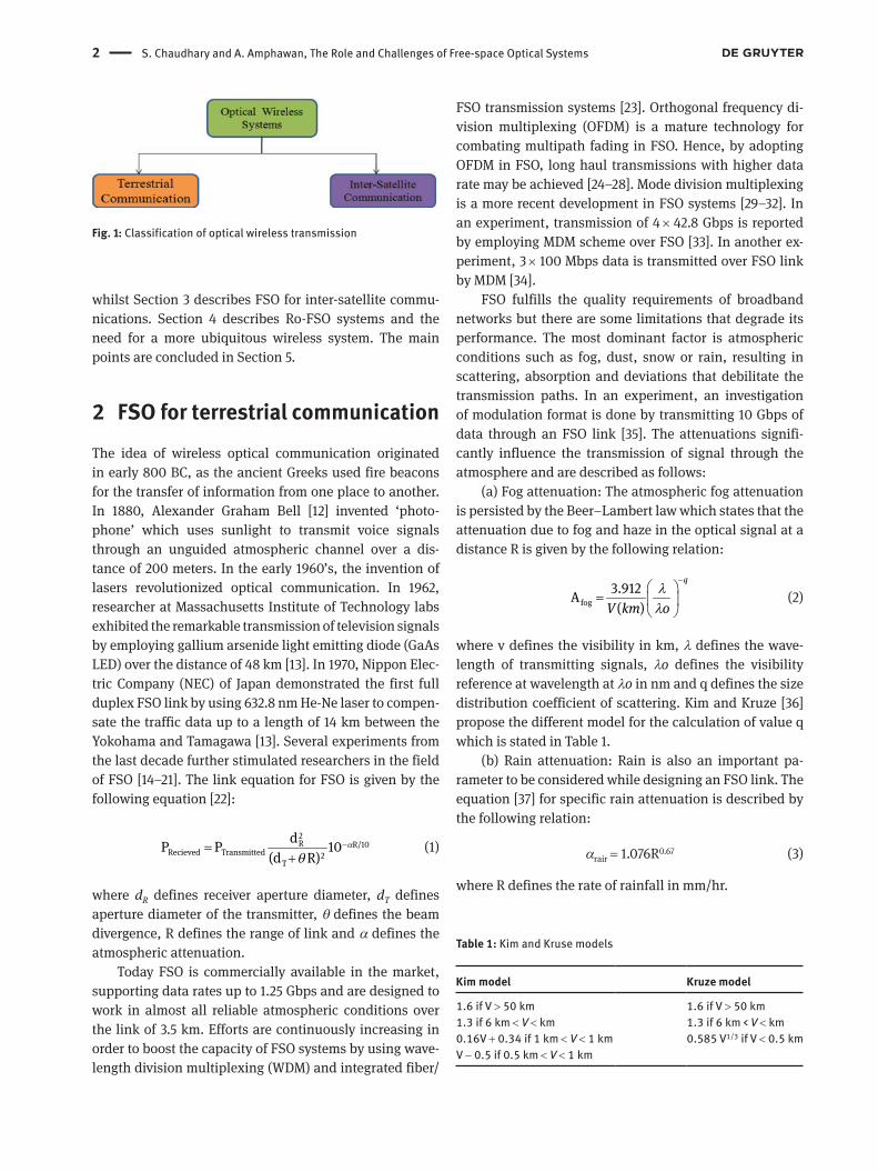
FSO may be broadly classified into FSO for terrestrial communication and FSO for inter-satellite communica-tion as shown in Fig. 1. This paper reviews the main fea-tures of FSO for terrestrial communications as well as inter-satellite communications. FSO simulations for trans-mission of 1 Gbps data through an FSO link are delineated as an attempt to illustrate possible signal degradations in an FSO link. The rest of the paper is organized as follows: Section 2 describes FSO for terrestrial communications
*Corresponding author: Sushank Chaudhary: InterNetworks Research Laboratory, School of Computing, Universiti Utara Malaysia, Sintok 6010, Malaysia. E-mail: [email protected] Amphawan: InterNetworks Research Laboratory, School of Computing, University Utara Malaysia, Sintok 6010, Malaysia; Research Laboratory of Electronics, Massachusetts Institute of Technology, Cambridge, USA
2 S. Chaudhary and A. Amphawan, The Role and Challenges of Free-space Optical Systems
whilst Section 3 describes FSO for inter-satellite commu-nications. Section 4 describes Ro-FSO systems and the need for a more ubiquitous wireless system. The main points are concluded in Section 5.
2 FSO for terrestrial communicationThe idea of wireless optical communication originated in early 800 BC, as the ancient Greeks used fire beacons for the transfer of information from one place to another. In 1880, Alexander Graham Bell [12] invented ‘photo- phone’ which uses sunlight to transmit voice signals through an unguided atmospheric channel over a dis-tance of 200 meters. In the early 1960’s, the invention of lasers revolutionized optical communication. In 1962, researcher at Massachusetts Institute of Technology labs exhibited the remarkable transmission of television signals by employing gallium arsenide light emitting diode (GaAs LED) over the distance of 48 km [13]. In 1970, Nippon Elec-tric Company (NEC) of Japan demonstrated the first full duplex FSO link by using 632.8 nm He-Ne laser to compen-sate the traffic data up to a length of 14 km between the Yokohama and Tamagawa [13]. Several experiments from the last decade further stimulated researchers in the field of FSO [14–21]. The link equation for FSO is given by the following equation [22]:
2R R/10
Recieved Transmitted 2T
dP P 10(d R)
α
θ
−=+
(1)
where dR defines receiver aperture diameter, dT defines aperture diameter of the transmitter, θ defines the beam divergence, R defines the range of link and α defines the atmospheric attenuation.
Today FSO is commercially available in the market, supporting data rates up to 1.25 Gbps and are designed to work in almost all reliable atmospheric conditions over the link of 3.5 km. Efforts are continuously increasing in order to boost the capacity of FSO systems by using wave-length division multiplexing (WDM) and integrated fiber/
FSO transmission systems [23]. Orthogonal frequency di-vision multiplexing (OFDM) is a mature technology for combating multipath fading in FSO. Hence, by adopting OFDM in FSO, long haul transmissions with higher data rate may be achieved [24–28]. Mode division multiplexing is a more recent development in FSO systems [29–32]. In an experiment, transmission of 4 × 42.8 Gbps is reported by employing MDM scheme over FSO [33]. In another ex-periment, 3 × 100 Mbps data is transmitted over FSO link by MDM [34].
FSO fulfills the quality requirements of broadband networks but there are some limitations that degrade its performance. The most dominant factor is atmospheric conditions such as fog, dust, snow or rain, resulting in scattering, absorption and deviations that debilitate the transmission paths. In an experiment, an investigation of modulation format is done by transmitting 10 Gbps of data through an FSO link [35]. The attenuations signifi-cantly influence the transmission of signal through the atmosphere and are described as follows:
(a) Fog attenuation: The atmospheric fog attenuation is persisted by the Beer–Lambert law which states that the attenuation due to fog and haze in the optical signal at a distance R is given by the following relation:
fog3.912A( )
q
V km oλ
λ
−
=
(2)
where v defines the visibility in km, λ defines the wave-length of transmitting signals, λo defines the visibility reference at wavelength at λo in nm and q defines the size distribution coefficient of scattering. Kim and Kruze [36] propose the different model for the calculation of value q which is stated in Table 1.
(b) Rain attenuation: Rain is also an important pa-rameter to be considered while designing an FSO link. The equation [37] for specific rain attenuation is described by the following relation:
αrair = 1.076R0.67 (3)
where R defines the rate of rainfall in mm/hr.
Fig. 1: Classification of optical wireless transmission
Table 1: Kim and Kruse models
Kim model Kruze model
1.6 if V > 50 km 1.6 if V > 50 km1.3 if 6 km < V < km 1.3 if 6 km < V < km0.16V + 0.34 if 1 km < V < 1 km 0.585 V1/3 if V < 0.5 kmV − 0.5 if 0.5 km < V < 1 km
S. Chaudhary and A. Amphawan, The Role and Challenges of Free-space Optical Systems 3
(c) Snow attenuation: The equation for the snow at-tenuation is given by the following relation [38]:
λsnow = α.Sb (4)
where S describes the rate of snowfall in mm/hr and α & b are given according to ITU recommendations as shown in Table 2.
(d) Scintillation effect: Scintillations are also a domi-nant factor in FSO both in terrestrial communication as well as space communication as the optical signal is fluc-tuated by the transient dips caused due to change in re-fractive index of the medium. Atmospheric scintillation is given by the following equation:
7/6
6 2 11scintt 6
2A 2 23.17 10 nc lπ
δ
= ∗ ∗ ∗
(5)
where δ is the wavelength in nm, l is the range in meter and 2
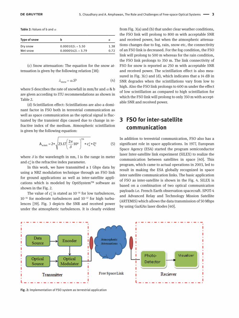
nc is the refractive index parameter.In this work, we have transmitted a 1 Gbps data by
using a NRZ modulation technique through an FSO link for ground applications as well as inter-satellite appli-cations which is modeled by OptiSystemTM software as shown in the Fig. 2.
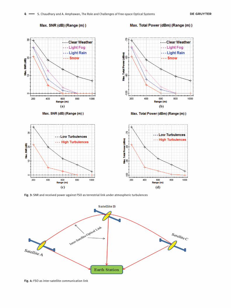
The value of 2nc is stated as 10−16 for low turbulences,
10−14 for moderate turbulences and 10−12 for high turbu-lences [39]. Fig. 3 depicts the SNR and received power under the atmospheric turbulences. It is clearly evident
from Fig. 3(a) and (b) that under clear weather conditions, the FSO link will prolong to 800 m with acceptable SNR and received power, but when the atmospheric attenua-tions changes due to fog, rain, snow etc, the connectivity of an FSO link is decreased. For the fog condition, the FSO link will prolong to 500 m whereas for the rain condition, the FSO link prolongs to 350 m. The link connectivity of FSO for snow is reported as 250 m with acceptable SNR and received power. The scintillation effect is also mea-sured in Fig. 3(c) and (d), which indicates that a 14 dB in SNR degrades when the scintillations vary from low to high. Also the FSO link prolongs to 600 m under the effect of low scintillation as compared to high scintillation for which the FSO link will prolong to only 350 m with accept-able SNR and received power.
3 FSO for inter-satellite communication
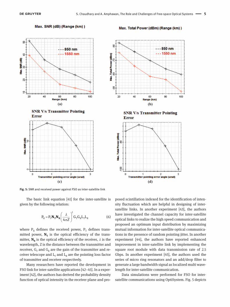
In addition to terrestrial communication, FSO also has a significant role in space applications. In 1977, European Space Agency (ESA) started the program semiconductor laser Inter-satellite link experiment (SILEX) to realize the communication between satellites in space [40]. This program, which came to actual operations in 2003, led to result in making the ESA globally recognized in space inter satellite communication links. The basic application of FSO as inter-satellite is shown in the Fig. 4. SILEX is based on a combination of two optical communication payloads i.e. French Earth observation spacecraft. SPOT-4 and Advanced Relay and Technology Mission Satellite (ARTEMIS) which allows the data transmission of 50 Mbps by using GaAlAs laser diodes [40].
Fig. 2: Implementation of FSO system as terrestrial application
Table 2: Values of b and α
Type of snow b α
Dry snow 0.000102λ + 5.50 1.38Wet snow 0.0000542λ + 3.79 0.72
4 S. Chaudhary and A. Amphawan, The Role and Challenges of Free-space Optical Systems
Fig. 3: SNR and received power against FSO as terrestrial link under atmospheric turbulences
Fig. 4: FSO as inter-satellite communication link
S. Chaudhary and A. Amphawan, The Role and Challenges of Free-space Optical Systems 5
The basic link equation [41] for the inter-satellite is given by the following relation:
2
R T T R T RP P G G L L4 Z
λ
π
=
T RN N (6)
where PR defines the received power, PT defines trans-mitted power, NT is the optical efficiency of the trans-mitter, NR is the optical efficiency of the receiver, λ is the wavelength, Z is the distance between the transmitter and receiver, GT and GR are the gain of the transmitter and re-ceiver telescope and LT and LR are the pointing loss factor of transmitter and receiver respectively.
Many researchers have reported the development in FSO link for inter-satellite applications [42–45]. In a exper-iment [42], the authors has derived the probability density function of optical intensity in the receiver plane and pro-
posed scintillation indexed for the identification of inten-sity fluctuation which are helpful in designing of inter- satellite links. In another experiment [43], the authors have investigated the channel capacity for inter-satellite optical links to realize the high speed communication and proposed an optimum input distribution by maximizing mutual information for inter-satellite optical communica-tions in the presence of random pointing jitter. In another experiment [44], the authors have reported enhanced improvement in inter-satellite link by implementing the square root module with data transmission rate of 2.5 Gbps. In another experiment [45], the authors used the series of micro ring resonators and an add/drop filter to generate a large bandwidth signal as localized multi wave-length for inter-satellite communication.
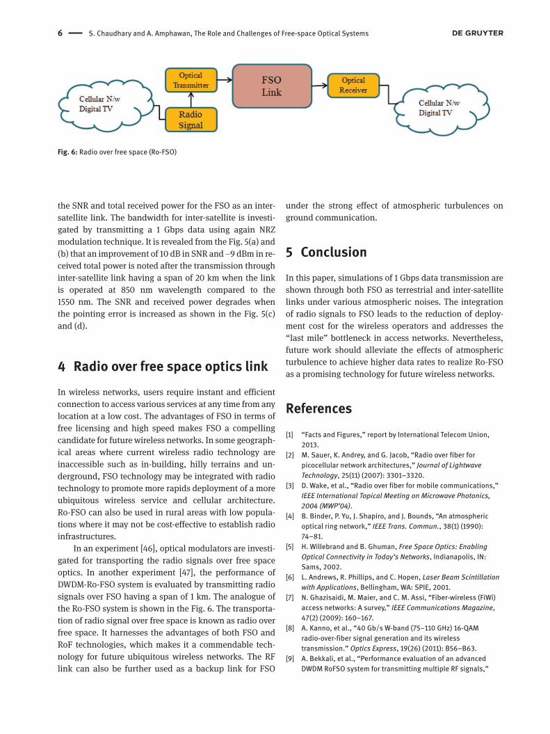
Data simulations were performed for FSO for inter- satellite communications using OptiSystem. Fig. 5 depicts
Fig. 5: SNR and received power against FSO as inter-satellite link
6 S. Chaudhary and A. Amphawan, The Role and Challenges of Free-space Optical Systems
the SNR and total received power for the FSO as an inter- satellite link. The bandwidth for inter-satellite is investi-gated by transmitting a 1 Gbps data using again NRZ modulation technique. It is revealed from the Fig. 5(a) and (b) that an improvement of 10 dB in SNR and −9 dBm in re-ceived total power is noted after the transmission through inter-satellite link having a span of 20 km when the link is operated at 850 nm wavelength compared to the 1550 nm. The SNR and received power degrades when the pointing error is increased as shown in the Fig. 5(c) and (d).
4 Radio over free space optics linkIn wireless networks, users require instant and efficient connection to access various services at any time from any location at a low cost. The advantages of FSO in terms of free licensing and high speed makes FSO a compelling candidate for future wireless networks. In some geograph-ical areas where current wireless radio technology are inaccessible such as in-building, hilly terrains and un-derground, FSO technology may be integrated with radio technology to promote more rapids deployment of a more ubiquitous wireless service and cellular architecture. Ro-FSO can also be used in rural areas with low popula-tions where it may not be cost-effective to establish radio infrastructures.
In an experiment [46], optical modulators are investi-gated for transporting the radio signals over free space optics. In another experiment [47], the performance of DWDM-Ro-FSO system is evaluated by transmitting radio signals over FSO having a span of 1 km. The analogue of the Ro-FSO system is shown in the Fig. 6. The transporta-tion of radio signal over free space is known as radio over free space. It harnesses the advantages of both FSO and RoF technologies, which makes it a commendable tech-nology for future ubiquitous wireless networks. The RF link can also be further used as a backup link for FSO
under the strong effect of atmospheric turbulences on ground communication.
5 ConclusionIn this paper, simulations of 1 Gbps data transmission are shown through both FSO as terrestrial and inter-satellite links under various atmospheric noises. The integration of radio signals to FSO leads to the reduction of deploy-ment cost for the wireless operators and addresses the “last mile” bottleneck in access networks. Nevertheless, future work should alleviate the effects of atmospheric turbulence to achieve higher data rates to realize Ro-FSO as a promising technology for future wireless networks.
References[1] “Facts and Figures,” report by International Telecom Union,
2013.[2] M. Sauer, K. Andrey, and G. Jacob, “Radio over fiber for
picocellular network architectures,” Journal of Lightwave Technology, 25(11) (2007): 3301–3320.
[3] D. Wake, et al., “Radio over fiber for mobile communications,” IEEE International Topical Meeting on Microwave Photonics, 2004 (MWP’04).
[4] B. Binder, P. Yu, J. Shapiro, and J. Bounds, “An atmospheric optical ring network,” IEEE Trans. Commun., 38(1) (1990): 74–81.
[5] H. Willebrand and B. Ghuman, Free Space Optics: Enabling Optical Connectivity in Today’s Networks, Indianapolis, IN: Sams, 2002.
[6] L. Andrews, R. Phillips, and C. Hopen, Laser Beam Scintillation with Applications, Bellingham, WA: SPIE, 2001.
[7] N. Ghazisaidi, M. Maier, and C. M. Assi, “Fiber-wireless (FiWi) access networks: A survey,” IEEE Communications Magazine, 47(2) (2009): 160–167.
[8] A. Kanno, et al., “40 Gb/s W-band (75–110 GHz) 16-QAM radio-over-fiber signal generation and its wireless transmission.” Optics Express, 19(26) (2011): B56–B63.
[9] A. Bekkali, et al., “Performance evaluation of an advanced DWDM RoFSO system for transmitting multiple RF signals,”
Fig. 6: Radio over free space (Ro-FSO)
S. Chaudhary and A. Amphawan, The Role and Challenges of Free-space Optical Systems 7
IEICE Transactions on Fundamentals of Electronics, Communications and Computer Sciences, 92(11) (2009): 2697–2705.
[10] A. M. Kabbour, et al., “Comparison of single mode fiber and multimode fiber in deployment of SCM-OCDMA in local area network,” Key Engineering Materials, 594 (2014): 1037–1040.
[11] A. M. Kabbour, et al., “Selective mode excitation in SCM-OCDMA,” IEEE 4th International Conference on Photonics (ICP), 2013.
[12] A. G. Bell, “On the production and reproduction of sound by light,” American Journal of Sciences, 3 (1880): 305–324.
[13] F. E. Goodwin, “A review of operational laser communication systems,” Proceedings of IEEE, 58 (1970): 1746–1752.
[14] S. Hardy, “Free space optics systems are finding their niches,” Lightwave, pp. 33–36, Dec. 2005.
[15] C. P. Colvero, M. C. R. Cordeiro, G. V. de Faria, and J. P. von der Weid, “Experimental comparison between far- and near infrared wavelenghts in free space optical systems,” Microwave and Optical Technology Letters, 46 (2005): 319–323.
[16] R. Dennis, L. Mark, G. Ganesh, P. Bruce, and N. Gerald, “Optical wireless propagation, theory v/s experiment,” Proceedings of SPIE: Optical Wireless Communications III, 4214 (2001): 38–45.
[17] E. Korevaar, I. I. Kim, and B. McArthur, “Atmospheric propagation characteristics of highest importance to commercial free space optics,” Proceeding of SPIE, 4976 (2003): 1–12.
[18] D. Song, et al., “4×10 Gb/s terrestrial optical free space transmission over 1.2 km using an EDFA preamplifier with 100 GHz channel spacing,” Optics Express, 7 (2000): 280–284.
[19] B. Flecker, E. Leitgeb, S. Sheikh Muhammad, C. Chlestil, E. Duca, and V. Carrozzo, “Measurement of light attenuation in fog and snow conditions for terrestrial FSO links,” 15th IST Mobile and Wireless Communications Summit, June 2006.
[20] M. D’Amico, A. Leva, and B. Micheli, “Free-space optics communication systems: first results from a pilot field-trial in the surrounding area of Milan, Italy,” IEEE Microwave and Wireless Components Letters, 13 (2003): 305–307.
[21] H. A. Fadhil, et al., “Optimization of free space optics parameters: An optimum solution for bad weather conditions,” Optik-International Journal for Light and Electron Optics, 124(19) (2013): 3969–3973.
[22] S. Bloom, E. Korevaar, J. Schuster, and H. Willebrand, “Understanding the performance of free-space optics,” Journal of Optical Networking, 2(6) (2003): 178–200.
[23] K. Kazaura, K. Omae, T. Suzuki, M. Matsumoto, E. Mutafungwa, T. Murakami, K. Takahashi, H. Matsumoto, K. Wakamori, and Y. Arimoto, “Performance evaluation of next generation free-space optical communication system,” IEICE Transaction of Electronics, vol. E90-C (2007): 381–388.
[24] V. Sharma and S. Kumar, “Empirical evaluation of wired- and wireless-hybrid OFDM-OSSB-RoF transmission system,” Optik – International Journal for Light and Electron Optics, 124(20) (2013): 4529–4532.
[25] V. Sharma and S. Chaudhary, “Implementation of hybrid OFDM-FSO transmission system,” International Journal of Computer Applications, 58(8) (2012): 37–40.
[26] V. Sharma and S. Chaudhary, “High speed CO-OFDM-FSO transmission system,” Optik – International Journal for Light and Electron Optics, 125(6) (2014): 1761–1763.
[27] I. B. Djordjevic, B. Vasic, and M. A. Neifeld, “LDPC coded OFDM over the atmospheric turbulence channel,” Optics Express, 15(10) (2007): 6336–6350.
[28] I. B. Djordjevic and H. G. Batshon, “LDPC-coded OFDM for heterogeneous access optical networks,” IEEE Photonics Journal, 2(4) (2010): 611–619.
[29] G. Gibson, et al., “Free-space information transfer using light beams carrying orbital angular momentum,” Optics Express, 12(22) (2004): 5448–5456.
[30] J. A. Anguita, M. A. Neifeld, and B. V. Vasic, “Turbulence-induced channel crosstalk in an orbital angular momentum-multiplexed free-space optical link,” Applied Optics, 47(13) (2008): 2414–2429.
[31] T. Su, et al., “Demonstration of free space coherent optical communication using integrated silicon photonic orbital angular momentum devices,” Optics Express, 20(9) (2012): 9396–9402.
[32] H. Huang, et al., “100 Tbit/s free-space data link enabled by three-dimensional multiplexing of orbital angular momentum, polarization, and wavelength,” Optics Letters, 39(2) (2014): 197–200.
[33] J. Wang, et al., “Terabit free-space data transmission employing orbital angular momentum multiplexing,” Nature Photonics, 6(7) (2012): 488–496.
[34] J. A. Anguita and C. Quezada, “Demonstration of orbital-angular-momentum-based multiple-channel free-space communication,” Latin America Optics and Photonics Conference, Optical Society of America, 2012.
[35] S. Chaudhary, P. Bansal, and G. Singh, “Implementation of FSO network under the Impact of atmospheric turbulences,” International Journal of Computer Applications, 75(1) (2013): 34–38.
[36] I. I. Kim, B. McArthur, and E. Korevaar, “Comparison of laser beam propagation at 785 nm and 1550 nm in fog and haze for optical wireless communications,” Proc. SPIE, 4214, Boston, MA, USA, 2001.
[37] T. H. Carbonneau and D. R. Wisley, “Opportunities and challenges for optical wireless: The competitive advantage of free space telecommunications links in today crowded market place,” SPIE Conference on Optical Wireless Communications, Massachusetts, pp. 119–128, 1998.
[38] Muhammad, S. Sheikh, P. Kohldorfer, and E. Leitgeb, “Channel modeling for terrestrial free space optical links,” Proceedings of 7th IEEE International Conference on Transparent Optical Networks, Vol. 1, 2005.
[39] P. S. Ray, “Broadband complex refractive indices of ice and water,” in Applied Optics, vol. 11, 1972.
[40] G. Oppenhauser, “Silex program status – A major milestone is reached,” Proc. SPIE, 2990 (1997): 2–9.
[41] A. Polishuk and S. Arnon, “Optimization of a laser satellite communication system with an optical preamplifier,” J. Optical Society of America, 21(7) (2004): 1307–1315.
[42] X. Li, et al., “Investigation of optical intensity fluctuation in the presence of satellite vibration for intersatellite optical communications,” IEEE International Conference on Computer Science and Network Technology (ICCSNT), Vol. 1, 2011.
[43] X. Li, et al., “Optimum signal input distribution design in the presence of random pointing jitter for intersatellite optical

8 S. Chaudhary and A. Amphawan, The Role and Challenges of Free-space Optical Systems
communications,” Optics and Laser Technology, 45 (2013): 705–707.
[44] V. Sharma and N. Kumar, “Improved analysis of 2.5 Gbps-inter-satellite link (ISL) in inter-satellite optical-wireless communication (IsOWC) system,” Optics Communications, 286 (2013): 99–102.
[45] A. Shahidinejad, et al., “Solitonic pulse generation for inter-satellite optical wireless communication,” Quantum Matter, 3(2) (2014): 150–154.
[46] K. Prabu, S. Bose, and D. S. Kumar, “Analysis of optical modulators for radio over free space optical communication systems and radio over fiber systems,” Annual IEEE India Conference (INDICON), 2012.
[47] P. T. Dat, et al., “Performance evaluation of an advanced DWDM RoFSO system for heterogeneous wireless,” Proceedings of the 28th IEEE Conference on Global Telecommunications, 2009.