GENERAL CATALOGUE - LNX
199
www.lennoxemea.com GENERAL CATALOGUE
-
Upload
khangminh22 -
Category
Documents
-
view
1 -
download
0
Transcript of GENERAL CATALOGUE - LNX

www.lennoxemea.com
GENERAL CATALOGUE

1
AQUALEAN - FLATAIR - COMPACTAIR 63
FIC/FIH/FIX - FSC/FSH - CIC/CIH - CSC/CSH - ASC/ASH 78
eNeRGy 27
eNeRGy+ 33
2
eCOMFORT - ECOLEAN - AQUA4 - NEOSYS 87
HYDROLEAN - MWC/MRC 111
FC/FI NEOSTAR - V-KING - NEOSTAR - MXW 124
ALLEGRA - COMFAIR HD - COMFAIR HH/HV - ARIA 2 - INALTO 136
ARMONIA 157
CLEANAIR LX 165
AXIL - EQUITHERM 168
@DNOVA 174
INNOV@ - INNOV@ ENERGY INVERTER - INNOV@ DFCDR/DSCDR 177
R@CKCOOLAIR 188
ADALINK II - LennoxVision - LennoxOneWebLennoxCloud - LennoxHydroControl 194
BALTIC - FLEXAIR 43
| Non-contractual illustrations | GC18-E_V4 |
Fan coil units
Water cassettes
Air handling units
Unit heaters/Destratifi er fans
Air cooled rooftop packaged units
Facts and fi gures • Production centers • Training Center • Our engagementsF-Gas and Ecodesign information • A world of applications
Rooftop packaged units
Packaged air conditioners
Split units
Commercial packaged and split air units
High effi ciency packaged air treatment unit
Introduction
Air cooled chillers/heat pumps
Water cooled chiller & Heat pump / Condenserless liquid chiller
Dry coolers & air cooled condensers
Chillers & Heat pumpsAir cooled condensers & dry-coolers
Airside products
Telecom units
Close control units
“In Row” close control unit for high density system
Close control units
Controls & Supervision

2 | Non-contractual illustrations | GC18-E_V4 |
LENNOX EMEA (Europe Middle-East Africa), part of Lennox International Incorporated (LII) is a leading provider of climate control solutions for heating, air conditioning and refrigeration markets and has the commitment to assisting its customers in their projects, to provide optimized and sustainable solutions.
LENNOX EMEA ensures that each employee fl ourishes within the group, so as to contribute to the success of our customers’ projects. Every day we develop our reputation by providing maximum comfort and effi ciency through our air conditioning and refrigeration solutions.
Our reputation as a leading market player is based on simple principles that guide our action: capacity to listen to our customers, knowledges of their fi elds of applications and understanding of their needs.
The devotion and expertise of all employees of LENNOX EMEA are key assets in building the trust shown to us by our customers every day and in ensuring the continuity of our relations.
More than ever, LENNOX EMEA is committed to meeting the challenges of tomorrow, by your side.
Ricardo FREITASVP, Managing Director LENNOX EMEA
Facts and figures
9 800 people
1 000 permanent people
3,84Billion $ turnover in 2016. Quoted on NYSE
LENNOX EMEA(EUROPE, MIDDLE EAST, AFRICA)
Presence on
5 continents
Quality standards : ISO 9001
Environmental standards :ISO 14001
Occupational health and safety management systems(*) : OHSAS 18001(*) : Longvic production site
LENNOX EMEA UNIVERSITY : More than
700 hours of bespoke training provided each year for our teams and our customers’ teams
3 commercial brands: Lennox, Friga Bohn, HK Refrigeration.
3 Europeanproduction sites
1 HVAC&R European development center
Commercial presence in
46 countries
LENNOX INTERNATIONAL

3| Non-contractual illustrations | GC18-E_V4 |
HEAD OFFICE EMEA :Lyon (France)
CURRENT DISTRIBUTION NETWORK :Algeria, Bahrain, Belarus, Botswana, Bulgaria, Croatia, Cyprus, Czech Republic, Denmark, Ghana, Greece, Hungary, India, Iraq, Israel, Jordan, Kazakhstan, Kuwait, Latvia, Lebanon, Morocco, Norway, Oman, Romania, Russia, Serbia, Slovakia, Slovenia, South Africa, Sweden, Switzerland, Tunisia, Turkey, Ukraine, Yemen.
SUBSIDIARIES AND REPRESENTATIVE OFFICES :Belgium and Luxembourg, France, Germany, Italy, Poland, Portugal, Spain, The Netherlands, United Arab Emirates, United Kingdom.
EUROPEAN PRODUCTION AND R&D SITES :Burgos (Spain): PlantDijon, Lyon (France): PlantsLyon (France): European Development center
Our production centersLENNOX EMEA has 3 production sites located in France and Spain.Customer focus and Lean concept has driven the evolution of these factories for years, and result in a very fl exible and effi cient organization ready to meet customer needs, even outside our standard portfolio.
GENAS (FRANCE) (Lyon area)
This 14000 sqm plant produces medium and large scroll chillers as also refrigeration equipments. This plant is also fully autonomous in sheet metal manufacturing.
BURGOS (SPAIN) (between Madrid and San Sebastian),
This 7000 sqm plant produces monobloc units and ductable splits, small and medium chillers and rooftops.
LONGVIC (FRANCE) (Dijon area)
This 13000 sqm plant is dedicated to rooftop assembly, with its own sheet metal facility.
As of today, the majority of our products are EUROVENT certified.With this program, we remain resolutely committed to reinforcing integrity and transparency in our commercial relationship with
our customers.
PRODUCTS CERTIFICATIONS
The manufactured units comply with EEC regulations, and each year an approved organism carries out a specifi c audit to check conformity with pressure equipment directives.

4 | Non-contractual illustrations | GC18-E_V4 |
Our engagements
INNOVATIONTechnologies evolve, regulations too: the LENNOX EMEA R&D teams work to invent solutions that, day after day, improve the lives of our customers, responding to ever changing expectations :
• Ease of installation• Energy effi ciency: how to provide the highest level of
comfort while minimising energy costs• Reduction of maintenance frequencies and costs• Common solutions between HVAC and Refrigeration• Environmentally friendly solutions
We focus on the overall cost of use of our solutions, from the start to the end of their lives.
LENNOX EMEA is really focused on innovation and just built a brand new development center.This European development center, located in Mions (Lyon area, France), has been designed to handle tests for both medium to high capacity HVAC products and Refrigeration equipments, and is qualifi ed for welcoming external inspectors for yearly Eurovent campaigns on Rooftop and Chillers (full load, seasonal effi ciencies).
On a 4000 m² site, product ranges are tested in one of our 5 tests chambers including Rooftop room, Chiller rooms, Refrigeration room and 2 Lifetest cold rooms.
The Rooftop room is the largest in Europe, able to qualify units up to 250 kW cooling capacity and 45.000 m3/h airfl ow. The tests can be run for temperatures between -15°C to +55°C.
Chiller units in cooling only or heat pump version up to 750 kW are qualifi ed in dedicated rooms, between -20°C and +55°C.
These test capabilities allow us to optimize and control seasonal effi ciencies of all of our units.
For chillers and rooftops, the tests are run according to new EN 14825 eco-design standard.
QUALITY As stated in our QSE Policy, LENNOX EMEA, with its employees and shareholders undertakes to supply its customers with products and services whose quality meets their requirements and expectations, both implicit and explicit.To do so, a dedicated Quality team, reporting directly and independently to the LENNOX EMEA General Management, works closely with every department to ensure that products and services meet our customers expectations at all time.
In all departments we are developing continuous improvement processes and all our production centers are ISO 9001 and ISO 14001 certifi ed, audited twice a year by our certifi cation companies – SGS in Spain and LRQA in France. Our Longvic plant is also ISO 18001 Certifi ed.
SERVICE
COMMISSIONING
PRE-SALESTRAINING
G
COMMISSIONINGASSISTANCE
REMOTE MONITORING
BMS
G
MANUFACTURERVISIT
AGREEMENT
WEEEECORECYCLING
R
ORIGINAL EQUIPMENT
REPLACEMENT PARTS
EQUIPMENT PERFORMANCE
CONTRACTE
MANUFACTURER AUDIT
MANUFACTURER ASSISTANCE
REFURBISHMENTREPAIR WORK
SYSTEM IMPROVEMENT

5
E M E A U N I V E R S I T Y
| Non-contractual illustrations | GC18-E_V4 |
Training Center
Our engagements
To increase your competitive advantage in an ever changing technological and regulatory environment, for refrigeration and air conditioning, LENNOX EMEA off ers you a European training center, to :
• Improve your operational knowledge • Optimise your professional activities• Become more competitive.
Modern and innovative, situated at the heart of one of our European manufacturing site in France, this complex benefi ts from all the experience and technological resources you would expect of an international manufacturer.
THE COURSESLENNOX EMEA University adapts itself to your requirements and trains you in the operation of our cooling and air conditioning systems to optimise energy management with greater respect for the environment:
• Regulation and control of air conditioning equipment • Commissioning, management and maintenance of machinery• Initiation and improvement in cooling technologies • Initiation and improvement in air conditioning• Building Management System• Specifi cation and rating of air conditioning plant• Handling, retrofi t of refrigerants
To enhance your refrigeration and air conditioning skills, in an ever changing technological and regulatory environment
LENNOX EMEA University off ers practical experience on a complete range of equipment, permanently installed at the disposition of students in test stations, exclusively dedicated to training.LENNOX EMEA University also off ers specially tailored courses; we will fi nd a solution suited to your specifi c requirements : content, date or place at your course.The courses combine alternate theoretical and practical modules and are sanctioned by a LENNOX EMEA certifi cate, the mark of quality for your customer and enable you to work on our equipment under the best conditions.
THE EQUIPMENT• 500 sqm dedicated to training• An audiovisual room to follow the theory courses in comfort• Roof top and chiller test stations• Real life test benches for unit products (Split, ducted, cabinet, etc. )• “System” workshops combining several types of unit.• Simulator for the programmed controllers in our range• A relaxation room for refreshments and meals
E-LEARNING• E-learning is an ideal solution if your busy lifestyle does not allow you to attend our
LENNOX EMEA University trainings.• Our student-centred and fl exible online subjects off er the
same rigorous learning requirements as our traditional courses.
PARTNER COMPANIES WHO FOLLOWED THE COURSES
AlcatelAuchanAximaCarrefourCegelec
City FacilitiesCofelyDalkiaElyo SuezIkea
Johnson ControlJtekMc Donald’sVeoliaand more ...

6
F-Gas EU No. 517/2014
| Non-contractual illustrations | GC18-E_V4 |
F-Gas regulations
Sustainable performancePerfectly aware of the importance of all ecologic issues, LENNOX EMEA is involved in :
• Planning and making commitments for the long term, conducive to the fulfi lment of everyone’s needs and the development of ever more effi cient and environmentally friendly solutions.
• Answering high environmental standards by developing low GWP solutions, respecting all environmental directives and our customers needs in energy consumption savings.
• All of our products, developed by a team of technical experts, meet the normative requirements Ecodesign and F-gaz. The design of products with natural fl uids such as CO2 is a major axis of development of LENNOX EMEA. We are eager to support our customers in these regulatory developments and off er them the best systems and services.
The contextThe chlorofl uorocarbon (CF) and hydrofl uorocarbon (HCFC) refrigerant fl uids used in cooling systems today are considered to be powerful greenhouse gases.To prevent climatic changes and global warming, the European Commission has adopted a roadmap to reduce global emissions by 2050.This directive, which relates to EU regulation No. 517/2014, is called F-Gas:
• Defi nes rules regarding containment, use, recovery and destruction of fl uorinated greenhouse gases and related measures.
• Defi nes the conditions for introduce on the market certain products and equipment containing HFCs.• Imposes conditions on certain specifi c uses of fl uorinated greenhouse gases.• Sets quantitative limits (quotas) for marketing HFCs.
This decree is for all companies that install, maintain and sell equipments containing refrigerant fl uids, as well as those handling and distributing them.
Prevention and restrictions
Prevention of fl uorinated greenhouse gas emissionsThe (EU) regulation No. 517/2014 imposes the rules concerning fl uorinated greenhouse gas used in air conditioning and refrigeration applications.All equipment must be designed to prevent accidental discharge of greenhouse gas.
PROCEDURESTraining & certifi cation
Records – Labelling
“PHASE DOWN"Reduction of HFC
(79% by 2030
NEW INSTALLATIONIn 2020, ban on GWP 2500 (depending on application)
INSTALLATION & MAINTENANCE
Containment measures: inspection for tightness and leaks
Our engagements
Sustainable development

7
31%
93%
63%
45%
24% 21%
100%100%
80%
60%
40%
20%
0%
2015 20162017
20182020
20212023
20242026
20272029
2030
| Non-contractual illustrations | GC18-E_V4 |
Provisions relating to the recycling of waste electrical and electronic equipment (WEEE):Directive 2002/96/CE aims to make recycling of WEEE (Waste Electronic and Electrical Equipment) mandatory.As a manufacturer of heat exchange equipment, LENNOX is a member of an Eco Organisation approved by Ministerial Decree of 19/12/2012 and supports you in the recycling of your equipment.
F-Gas regulationsThe F-Gas recommendation on fl uorinated fl uids imposes :
• Bans of some refrigerant for some applications• Frequent inspections (with or without leak protection systems)• Qualifi cation of companies and participants.
Usage restrictions for new equipment:Concerning air conditioning applications, the only regulatory point to be taken into account is the following one :
Year of prohibitionGWP
(Global warming potential)Applications/prohibitions
2025 GWP 750 Residential air conditioning (bilateral blocks) containing less than 3 kg of greenhouse gas.
Perfectly aware of the importance of all ecologic issues, LENNOX EMEA have been working hardly since a long time, on alternative solutions reducing as much as possible the environmental impact of their units.
Phase down :The Global Warming Potential (GWP) enables to measure the polluting potential of each refrigerant.The (EU) regulation Nr 517/2014 sets quantitative limits (quotas) to place HFCs on the market, following a calendar running from 2015 to 2030.
The phase down measure establishes a gradual decrease in gas measured with global warming potential (cf diagram)
Reference values and quotas for placing hydrofl uorocarbons on the market (in tons of CO2 equivalent)
Our engagements

8 | Non-contractual illustrations | GC18-E_V4 |
Ecodesign directive 2009/125/ECGENERAL INFORMATION
1st June 2017
Ecodesign: origins & perspectives• KYOTO (1997), COP21 (Paris 2015) and COP 22 (Marrackech 2016) defi ne the targets to restrict the global warming to
1,5°C.
• Ecodesign directive 2009/125/EC defi ne a framework for all energy-consuming equipments. It is mandatory for all products sold and used in European Union.
• The regulations resulting from Ecodesign defi ne, for each product family, minimum effi ciencies to achieve in 2 steps.
The regulation ensue from Ecodesign are mandatory to apply, even if the local governments don’t implement them into national regulations or decrees:
The following directive are not connected to Ecodesign, but they are also directives and European regulations:
• F gaz (517/2014/EU) Fluorinated greenhouse gases used,
• DESP (2014/68/EU) for pressure equipment,
• DEEE (2012/19/EU) for waste electrical and electronic equipment,
• Machinery directive (2006/42/EC),
• Low voltage directive (2014/35/EU),
• Electromagnetic compatibility (2014/30/EU)….
Rules
• Electric motors EC 640/2009: 1st tier: 16th june 2011 . . . . . . motors IE2 2nd tier: 1st january 2015 . . . motors IE3 if P>7.5 kW 3rd tier: 1st january 2017 . . . moteurs IE3
• Fans EU 327/2011: 1st tier: 1st january 2013 2nd tier: 1st january 2015
• Air conditioners (P<12 kW) and comfort fans EU 206/2012:
1st tier: 1st january 2013 2nd tier: 1st january 2014
• Ventilation units EU 1253/2014: 1st tier: 1st january 2016 2nd tier: 1st january 2018
• Space heaters and combination heaters EU 813/2013: 1st tier: 26th september 2015 2nd tier: 26th september 2017
• Low temperature process chillers and condensing units EU 2015/1095 (dedicated to industrial application and/or refrigeration):
1st tier: 1st July 2016 2nd tier: 1st january 2018
• Air heating products, cooling products, high temperature process chillers and fan coil units EU 2016/2281:
1st tier: 1st July 2018 2nd tier: 1st january 2021

9
Item Symbol
Rated heating capacity (*) Prated, h
Tj = – 7 °C Pdh
Tj = + 2 °C Pdh
Tj = + 7 °C Pdh
Tj = + 12 °C Pdh
Tbiv = bivalente temperature ºC Pdh
TOL = opeation limit °C Pdh
For air to water heat pumps: Tj = – 15 °C (si TOL < – 20 °C) Pdh
Bivalent temperature Tbiv
Degration coefficent heat pumps (**) Cdh
Off mode POFF
Thermostat off mode PTO
Crankcase heater mode PCK
Capacity control
Sound power level indoor/outdoor measured LWA
Emission of nitrogen oxides (if applicable) NOx(**
GWP of the refrigerant
Model(s):
Outdoor side heat exchanger of heat pump:
Indoor side heat exchanger of heat pump:
Indication if the heater is equipped with a supplementary heater
If applicable: driver of compressor
Declared heating capacity for part load at indoor temperature 20°C and outdoor
Power consumption in modes other than "activ
Item Symbol
Seasonal space heating energy efficiency s
Tj = – 7 °C COPd
Tj = + 2 °C COPd
Tj = + 7 °C COPd
Tj = + 12 °C COPd
Tbiv = bivalente temperature ºC COPd
TOL = opeation limit °C COPd
For air to water heat pumps: Tj = – 15 °C (si TOL < – 20 °C) COPd
For water to air heat pumps: Operation limit temeprature TOL
Back up heating capcity (*) elbu
Type of enerrgy input
Stanby mode PSB
For air to air heat pumps: air flow rate, outdoor measured
CV
Other items
For water/brine to air heat pumps: Rated brine or water flowrate, outdoor side heat exchanger
Declared coefficient of performance or gas utilisation efficicency/auxiliary energy fatemperature Tj
Supplementary heater
BALTICR-FLEX
FLEXAIReNeRGy
138 %117 %
125 %115 %
100%125%
150%175%
200%
| Non-contractual illustrations | GC18-E_V4 |
It means that:
Are concerned since 1st January 2018:
• All the air to air rooftop units,
• All the water to air rooftop units
Since the 1st of January 2018, each unit is delivered with a datasheet as defined in EU 2281/2016.
Are not concerned:
• The units sold without condenser
The units equipped with « gas burner » option are not considered as “warm air heaters using fuels” but only as “rooftop air conditioners” or “rooftop heat pumps”.
ROOFTOP rangesRules EU 2016/2281
Which ROOFTOP range products are concerned by regulation EU 2016/2281 ?
A new document
Ranges concernedNominal capacity
Sound power levelOutdoor/Indoor
Seasonal efficiency
Minimal seasonal energy effi ciency
BALTIC & FLEXAIR, water cooled units
Concerned without minimum performance to achieve
eNeRGy without condenser
Range concerned by EU 2014/1253 (ventilation units)
1st january 2017/Rev 2018.02
The minimum performances to achieve are summed up in the following graph:

10
Item Symbol
Rated heating capacity (*) Prated, h
Tj = – 7 °C Pdh
Tj = + 2 °C Pdh
Tj = + 7 °C Pdh
Tj = + 12 °C Pdh
Tbiv = bivalente temperature ºC Pdh
TOL = opeation limit °C Pdh
For air to water heat pumps: Tj = – 15 °C (si TOL < – 20 °C) Pdh
Bivalent temperature Tbiv
Degration coefficent heat pumps (**) Cdh
Off mode POFF
Thermostat off mode PTO
Crankcase heater mode PCK
Capacity control
Sound power level indoor/outdoor measured LWA
Emission of nitrogen oxides (if applicable) NOx(***)
GWP of the refrigerant
Contact details
Model(s):
Outdoor side heat exchanger of heat pump:
Indoor side heat exchanger of heat pump:
Indication if the heater is equipped with a supplementary heater
If applicable: driver of compressor
Declared heating capacity for part load at indoor temperature 20°C and outdoor tem
Power consumption in modes other than "active m
Item Symbol
Seasonal space heating energy efficiency s
Tj = – 7 °C COPd
Tj = + 2 °C COPd
Tj = + 7 °C COPd
Tj = + 12 °C COPd
Tbiv = bivalente temperature ºC COPd
TOL = opeation limit °C COPd
For air to water heat pumps: Tj = – 15 °C (si TOL < – 20 °C) COPd
For water to air heat pumps: Operation limit temeprature TOL
Back up heating capcity (*) elbu
Type of enerrgy input
Stanby mode PSB
For air to air heat pumps: air flow rate, outdoor measured
her items
For water/brine to air heat pumps: Rated brine or water flowrate, outdoor side heat exchanger
Declared coefficient of performance or gas utilisation efficicency/auxiliary energy fatemperature Tj
Supplementary heater
| Non-contractual illustrations | GC18-E_V4 |
UNITARY rangesRules EU 2016/2281
It means that :
Are concerned since 1st January 2018:
• Split and packaged air to air units,
• Water to air units
• Multi split and VRF units
Since the 1st of January 2018, each unit is delivered with a datasheet as defined in EU 2281/2016.
Nominal capacity
Sound power levelOutdoor/Indoor
Seasonal efficiency
Are not concerned:
• Air handling units sold separately (without condensing unit),
• The condensing units (without air treatment unit)
Which UNITARY range products are concerned by regulation EU 2016/2281 ?
A new document Ranges concerned
The minimum performances to achieve are summed up in the following graph:
Minimal seasonal energy effi ciency
AQUALEANThis range is concerned, but no minimum performance to achieve.
1st january 2017/Rev 2018.02
FLATAIR ADVANCEDCOMPACTAIR ADVANCED
VRF
138 %
125 %
117 %
115 %
SPLIT138 %
125 %
117 %
115 %
137 %
189 %
133 %
181 %
100%125%
150%175%
200%

11
Item Symbol
Rated heating capacity (*) Prated, h
Tj = – 7 °C Pdh
Tj = + 2 °C Pdh
Tj = + 7 °C Pdh
Tj = + 12 °C Pdh
Tbiv = bivalente temperature ºC Pdh
TOL = opeation limit °C Pdh
For air to water heat pumps: Tj = – 15 °C (si TOL < – 20 °C) Pdh
Bivalent temperature Tbiv
Degration coefficent heat pumps (**) Cdh
Off mode POFF
Thermostat off mode PTO
Crankcase heater mode PCK
Capacity control
Sound power level indoor/outdoor measured LWA
Emission of nitrogen oxides (if applicable) NOx(***)
GWP of the refrigerant
Contact details
Indoor side heat exchanger of heat pump:
Indication if the heater is equipped with a supplementary heater
If applicable: driver of compressor
(*)
Declared heating capacity for part load at indoor temperature 20°C and outdoor tem
Power consumption in modes other than "active m
Item Symbol
Seasonal space heating energy efficiency s
Tj = – 7 °C COPd
Tj = + 2 °C COPd
Tj = + 7 °C COPd
Tj = + 12 °C COPd
Tbiv = bivalente temperature ºC COPd
TOL = opeation limit °C COPd
For air to water heat pumps: Tj = – 15 °C (si TOL < – 20 °C) COPd
For water to air heat pumps: Operation limit temeprature TOL
Back up heating capcity (*) elbu
Type of enerrgy input
Stanby mode PSB
For air to air heat pumps: air flow rate, outdoor measured
her items
For water/brine to air heat pumps: Rated brine or water flowrate, outdoor side heat exchanger
Declared coefficient of performance or gas utilisation efficicency/auxiliary energy fatemperature Tj
Supplementary heater
<400 kWECOLEAN
eCOMFORTNEOSYS
>400 kWNEOSYS
<400 kWHYDROLEAN
MWC
>400 kWMWC
161 %
179 %161 %
200 %
252 %
196 %
227 %
227 %
125 %115 %
125 %115 %
149 %
100%125%
150%175%
200%225%
Minimal seasonal energy efficiency
| Non-contractual illustrations | GC18-E_V4 |
CHILLER rangesRules EU 2016/2281 & 813/2013
1st June 2017/Rev 2018.02
It means that:
Are concerned since 1st January 2018:
• Air cooled liquid chillers,
• Water cooled liquid chillers.
Are concerned since 26th September 2015:
• Air cooled heat pumps,
• Water cooled heat pumps.
Since the 1st of January 2018, each unit will be delivered with a datasheet as defined in EU 2281/2016.
Which CHILLERS range products are concerned by regulations EU 2016/2281 & 813/2013 ?
A new document Ranges concerned
Nominal capacity
Sound power levelOutdoor/Indoor
Seasonal efficiency
Minimal seasonal energy effi ciency
The minimum performances to achieve are summed up in the following graph:
According to EU 813/2013 rule.
According to EU 2016/2281 rule.

12
Item Symbol Value Unit Item Symbol Value UnitCooling capacity (sensible)
Prated, c kWTotal electric power input
Pelec kW
Cooling capacity (latent)
Prated, c kWSound power level (per speed setting if applicable)
LWA – dB
Heating capacity Prated, h kW
Contact details
Information to identify the model(s) to which the information relates:
Name and address of the manufacturer or of its authorised representative.
| Non-contractual illustrations | GC18-E_V4 |
FANCOIL rangesRules EU 2016/2281
1st january 2017
Since the 1st of January 2018, each unit is delivered with a datasheet as defined in EU 2281/2016.
A new document
Cooling capacity
Heating capacitySound power levelOutdoor/Indoor
Are not concerned:
• EQUITHERM units (encased ventilation fan, included in rule nr 327/2011).
Which FAN COILS ranges are concerned by regulation EU 2016/2281 ?
Ranges concerned
Are concerned since 1st January 2018:
• All the LENNOX fan coil units, but no minimum performance to achieve.

13| Non-contractual illustrations | GC18-E_V4 |
VENTILATION UNITSRule UE 1253/2014
1st january 2017
It means that :
Which VENTILATION UNITS are concerned by regulations UE 1253/2014 ?Are concerned since 1st january 2016 :
• The CLEANAIR LX air handling unit,
• The eNeRGy range, without condenser
Are not concerned:
• Ventilation units equiped with a thermodynamic energy recovery module
• Rooftops units (included in the rule nr UE2016/2281).
Unidirectional ventilation units (UVU) :Air stream from outside toward inside or from inside toward outside (with or without mixing section).
Requirements for unidirectional ventilation units (UVU) :
Bidirectional ventilation units (BVU)Air stream from outside toward inside and from inside toward outside (with or without mixing section).
Requirements for bidirectional ventilation units (BVU)
2016 2018
Fan effi ciency Please consult the texts of the rule nr UE1253/2014 or the selection software
Fan motor 3-speed or variable speed fan motor(may be installed by the installer)*
Clogging of the fi lter - Filter change warning signal (may be installed by the installer)*
2016 2018
Fan effi ciency Please consult the texts of the rule nr UE1253/2014 or the selection software
Fan motor 3-speed or variable speed fan motor(may be installed by the installer)*
Clogging of the fi lter - Filter change warning signal (may be installed by the installer)*
Fan absorbed power Please consult the texts of the rule nr UE1253/2014 or the selection software
Heat recovery module It must be possible to bypass the energy recovery system (by-pass system must be integrated in the unit).
Minimum effi ciency of the heat recovery system (SRC)
Please consult the texts of the rule nr UE1253/2014 or the selection software
According to the UE1253/2014 rule, the unidirectional ventilation units (UVU) are diffferent from the Bidirectional ventilation units (BVU).
* In accordance with the guidelines of the manufacturer.
ENERGY WITHOUT CONDENSEUR
Ranges concerned

14 | Non-contractual illustrations | GC18-E_V4 |
A world of applicationsNon food retail
Air cooled rooftop packaged unit
FLEXAIR 85 227 kW
Page 51
Chilled water cassetteARMONIA1,3 11 kW
Page 155
Fan coil unitALLEGRA0,6 6,7 kW
Page 135
Air treatment unitCIC/CIH
19 135 kWPage 82
Condensing unitASC/ASH
20 230 kWPage 83Vertical packaged air conditioner
COMPACTAIR9 83 kWPage 71
Air cooled chiller/Heat pumpeCOMFORT20 190 kW
Page 87

15| Non-contractual illustrations | GC18-E_V4 |
Packaged air treatment unit
eNeRGy50 180 kW
Page 27
Food retail
CO2 Compressor rackECO2GEN*
17 83 kW
CO2 transcritical booster rack eCO2BOOST50 250 kW
Air cooled chiller/Heat pumpeCOMFORT20 190 kW
Page 87
Unit heaterAXIL
12 105 kWPage 166
Cubic unit cooler3C*
1 35 kW
Axial fan condenserMXW
50 1670 kWPage 132
* : For more information on this product, please consult the refrigeration product catalogue
Air cooled rooftop packaged unitBALTIC 21 79 kWPage 43
"V shape" or "fl at bed"Gas cooler
A world of applications

16 | Non-contractual illustrations | GC18-E_V4 |
Refrigeration packaged unitEUROMON*
0,7 4,5 kW
Cubic unit cooler3C*
1 35 kW
* : For more information on this product, please consult the refrigeration product catalogue
Horizontal packaged air conditionerFLATAIR
6 34 kWPage 67
Encased outdoor condensing unit DUO CU*
6 49 kW
A world of applicationsConvenience store

17| Non-contractual illustrations | GC18-E_V4 |
Air cooled rooftop packaged unitBALTIC
21 79 kWPage 43
Water cooled rooftop packaged unit
BALTIC 21 79 kW
Page 43
Horizontal water cooled packaged air conditionerAQUALEAN
2 20 kWPage 63
Water cooled chiller/Heat pumpMWC
180 720 kWPage 117
LENNOX web serverADALINK
Page 192
Packaged air treatment unit
eNeRGy50 180 kW
Page 27
A world of applicationsShopping malls
18 | Non-contractual illustrations | GC18-E_V4 |
Air cooled rooftop packaged unitBALTIC 21 79 kWPage 43
Air cooled chiller/Heat pumpeCOMFORT20 190 kW
Page 87
* : For more information on this product, please consult the refrigeration product catalogue
Split system for wine cellarCLIMACAVE*
1,3 3,5 kW Cubic unit cooler3C*
1 35 kW
Condensing unitVANGUARD*
0,7 12,2 kW
Chilled water cassetteARMONIA1,3 11 kW
Page 155
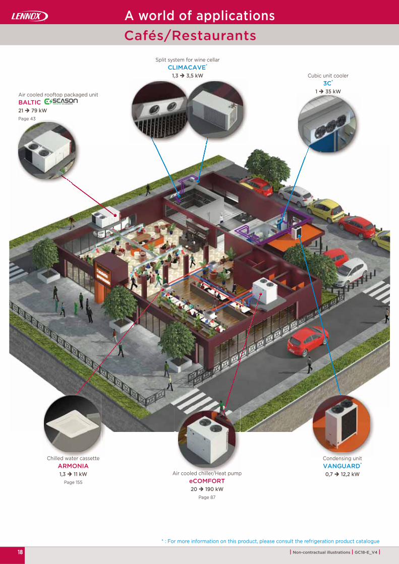
A world of applicationsCafés/Restaurants

19| Non-contractual illustrations | GC18-E_V4 |
Chilled water cassetteARMONIA1,3 11 kW
Page 155
Air cooled chiller/Heat pumpeCOMFORT20 190 kW
Page 87
Cubic unit cooler3C*
1 35 kW
Encased outdoor condensing unit
DUO CU4 49 kW
Industrial unit coolerGTA*
11 82 kW
* : For more information on this product, please consult the refrigeration product catalogue
Air cooled chiller/Heat pumpeCOMFORT20 190 kW
Page 87
A world of applicationsCentral kitchens

20 | Non-contractual illustrations | GC18-E_V4 |
“In Row” close control unit for high density systems
R@CKCOOLAIR3 75 kW
Page 186
Lennox HVAC hydronic systemLennoxHydroControl
Page 195
Modular air handling unitCLEANAIR LX1000 10000 m3/hPage 163
Air cooled chiller/Heat pumpNEOSYS
200 1000 kWPage 103
Chilled water cassetteARMONIA1,3 11 kW
Page 155
Ceiling mounted fan coil unitALLEGRA0,6 6,7 kW
Page 135
Polyvalent air cooled heat pumpAQUA4
50 320 kWPage 99
Dry coolerFC/FI NEOSTAR
20 1200 kWPage 124
A world of applicationsOffice Buildings

21| Non-contractual illustrations | GC18-E_V4 |
Modular air handling unitCLEANAIR LX
1000 10000 m3/hPage 163
Polyvalent air cooled heat pumpAQUA4
50 320 kWPage 99
Air cooled chiller/Heat pumpeCOMFORT20 190 kW
Page 87
Cubic unit cooler3C*
1 35 kW
Air cooled rooftop packaged unitBALTIC
21 79 kWPage 43
Fan coil unitALLEGRA0,6 6,7 kW
Page 135
Condensing unitVANGUARD*
0,7 12,2 kW
* : For more information on this product, please consult the refrigeration product catalogue
A world of applicationsHotel

22 | Non-contractual illustrations | GC18-E_V4 |
Cubic unit cooler3C*
1 35 kW
* : For more information on this product, please consult the refrigeration product catalogue
Compressor rackMOVSH*
70 700 kW
Industrial unit cooler
GTA*
11 82 kW
Centrifugal unit coolerNCN*
5 95 kW
Air cooled rooftop packaged unitBALTIC
21 79 kWPage 43
Industrial unit coolerNK*
7 130 kW
Packaged air treatment unit
eNeRGy50 180 kW
Page 27
CondenserMXW
50 1670 kWPage 132
A world of applicationsStorage and Logistic

23| Non-contractual illustrations | GC18-E_V4 |
Air cooled chiller/Heat pumpeCOMFORT20 190 kW
Page 87
Packaged air treatment unit
eNeRGy50 180 kW
Page 27
Air cooled chiller/Heat pumpNEOSYS
200 1000 kWPage 103
Dry coolerFC/FI NEOSTAR
20 1200 kWPage 124
Process to be cooled
Chilled water cassetteARMONIA1,3 11 kW
Page 155
A world of applicationsIndustry

24 | Non-contractual illustrations | GC18-E_V4 |
Dry coolerFC/FI NEOSTAR
20 1200 kWPage 124Close control unit
INNOV@6 240 kW
Page 175
Air cooled chiller/Heat pumpNEOSYS
200 1000 kWPage 103
Ceiling mounted fan coil unitALLEGRA0,6 6,7 kW
Page 135
A world of applicationsData Centers

2525| Non-contractual illustrations | GC18-E_V4 |
Compressor rackMOPSH*
22 385 kW
Industrial unit coolerNK*
7 130 kW
Blast freezing tunnel unit coolerNW*
4 63 kW
Industrial unit coolerGTA*
11 82 kW
slaughtering zone
Off alzone
Dry sweatingzone
Storage zone
Cubic unit cooler3C*
1 35 kW
Dry coolerFC NEOSTAR20 1200 kW
Page 124
Dry coolerFC NEOSTAR20 1200 kW
Page 124
Refrigeration applications
* : For more information on this product, please consult the refrigeration product catalogue
Food processing
Energy
V-shaped coil dry cooler
V-KING50 > 2000 kW
Page 127

26
|
eNeRGy50 180 kW 27
eNeRGy + 16 160 kW 33
• 40
| Non-contractual illustrations | GC18-E_V4 |
High efficiency packaged air treatment unit
High efficiency packaged air treatment unit
Standard equipments and options

27
eNeRGy
D I R E C T I V E 2 0 0 9 / 1 2 5 / E C
ECODESIGN
ErP
Energy efficiency
Indoor air quality
Modularity
Accurate control
Airfl ow rate :9500 - 32000 m3/h
Cooling capacity :50 - 180 kW
Heating capacity :50 - 180 kW
HIGH EFFICIENCY PACKAGED AIR TREATMENT UNIT
LENNOX participates in the ECP programme for RT.
Check ongoing validity of certifi cate :www.eurovent-certifi cation.com

28
50 180 kW9500 32000 m3/h
eNeRGy
| Non-contractual illustrations | GC18-E_V4 |
Main applicationsIndustry/LogisticCommercial HVAC
High effi ciency packaged air treatment unit
EC plug fan
Electronic expansion valve
ENERGY EFFICIENCY :
Axial fansWith optional EC motor High effi ciency indoor fan
Variable speed direct drive fan with eFlow airfl ow measurement and display eRecovery
Energy recovery on food refrigeration systems
Ecodesign compliant performances (EU 2016/2281) exceeding 2021 targets for cooling mode
ACCURATE CONTROL :
e-CLIMATIC Advanced controllerIntelligent controller to improve effi ciency and help set up and service
High effi ciency refrigeration circuitMultiscroll R410A compressorsElectronic expansion valves
A
Tandem compressors
2021READY
AIR COOLING PRODUCT
EU 2016/2281

29
eCLIMATIC
| Non-contractual illustrations | GC18-E_V4 |
INDOOR AIR QUALITY :
Filtration optionsSeveral levels of fi ltration :G4 / F7 (ePM1) / F9 (ePM1)
Innovative casing50 mm double skin casing, aluminium frame.
MODULARITY :
Extraction moduleWith EC fan technology
Integrated rotary hybrid wheelEspecially designed to transfer sensible (tempera-ture) and optional latent (humidity) heat from the exhaust air to the supply air.
ADALINK II : LENNOX WEB SERVEROne site/Several units
ADALINK II is the Lennox solution for managing air-conditioning and air-handling installations. It can be connected to various LENNOX units.• Simplifi ed BMS system• Small installations: up to 16 LENNOX units
LennoxCloud: LENNOX WEB PORTAL Multi sites/Multi units
LennoxCloud allows remote monitoring of unit operation across various customer sites. Thanks to LennoxCloud, LENNOX units can be remotely controlled, adjusted and diagnosed by our experts. It helps achieve signifi cant energy savings while optimising performance throughout the unit's life cycle.
LENNOX monitoring solutions
Heat recovery solutions
Cool
ing
and
heat
ing
capa
city
(kW
)
Building timeline

30
eNeRGy
ENERGY
E0
14 A
H 0
65
E0
19 A
H 0
86
E0
19 A
H 1
06
E0
24 A
H 1
08
E0
24 A
H 1
26
E0
24 A
H 1
41
kW 67,2 89,4 107,7 114,6 121,8 139,9
3,21 3,16 3,03 3,15 3,14 3,01
A
kW 65,1 86,2 106,1 109,3 118,1 140,1
3,45 3,37 3,27 3,53 3,54 3,22
A B B A A B
3,72 4,41 4,41 4,54 4,60 4,56
% 146 173 173 179 181 180
3,72 3,37 3,41 3,63 3,63 3,50
% 146 132 134 143 142 137
kW
82/130 100/200
36/108 54/144
69/122 81/146 81/146 117/188
m3/h
13500 18900 18900 24300 24300 24300
24000 24000 24000 32000 32000 32000
dB(A)
78,6 81,7 81,7 78,2 80,8 82
77,4 86,3 86,3 84 84,4 84,4
| Non-contractual illustrations | GC18-E_V4 |
To g
et t
he d
ata
of t
he c
omp
lete
ran
ge,
ple
ase
cons
ult
us
Nominal thermal performances - Cooling mode
Cooling capacity (1)
EER (1)
Eurovent energy effi ciency classFull load operation
Nominal thermal performances - Heating mode
Heating capacity (2)
COP (2)
Eurovent energy effi ciency classFull load operation
Seasonal effi cienciesSeasonal Energy Effi ciency RatioSEER (3)
Seasonal energy effi ciencyɳs,c (4)
Seasonal Coeffi cient of PerformanceSCOP (5)
Seasonal energy effi ciencyɳs,h (6)
Auxiliary heatingGas heating capacityStandard / High
Electric heater capacityStandard / HighHot water coil capacity(Air inlet 20°C / Water 90-70 °C)Standard / High
Ventilation
Nominal airfl ow rate
Maximum airfl ow rate
Acoustic dataOutdoor sound powerStandard unit (1)
Indoor blower outlet sound powerStandard unit (1)
Check ongoing validity of certifi cate :eurovent-certifi cation.com
(1) Cooling mode : According to EN14511 nominal conditions Outdoor temperature 35°C DB Indoor temperature 27°C DB / 19°C WB
(2) Heating mode : According to EN14511 nominal conditions Outdoor temperature 7°C DB / 6°C WB Indoor temperature 20°C DB
(3) SEER in accordance with standard EN14825.
(4) Space cooling energy effi ciency following Ecodesign regulation EU 2016/2281
(5) SCOP in accordance with standard EN 14825 (average climate conditions).
(6) Space heating energy effi ciency following Ecodesign regulation EU 2016/2281.
General data - Heat pump units
axi ESP
1000 Pa

31
eNeRGy
2275
2270
6150
612
6150
612
2275
2270
2275
2270
6751
612
2275612
6150
2270
E014 AH 065
E024 AH 108E024 AH 126E024 AH 141
E019 AH 086E019 AH 106
| Non-contractual illustrations | GC18-E_V4 |
Dimensions (vertical confi guration)
All drawings and dimensions are given for vertical confi guration.Units with condensing section and heat recovery wheel option
Horizontal confi guration, with heat recovery module
Vertical confi guration, without heat recovery module
Other possible confi gurations

32 | Non-contractual illustrations | GC18-E_V4 |

33
eNeRGy++
D I R E C T I V E 2 0 0 9 / 1 2 5 / E C
ECODESIGN
ErP 2021READY
AIR COOLING PRODUCT
n°2016/2281
2021READY
AIR HEATING PRODUCT
n°2016/2281
Reduced energy bill
All seasons operation
Very high comfort level
Reliability
Airfl ow rate :Up to 32000 m3/h
Cooling capacity :16 - 160 kW
Heating capacity :16 - 160 kW
HIGH EFFICIENCY PACKAGED AIR TREATMENT UNIT
* Nominal heating conditions (EN14511) - At partial load
LENNOX participates in the ECP programme for RT.Check ongoing validity of certifi cate :
www.eurovent-certifi cation.com

34
eNeRGy ++16 160 kW10500 32000 m3/h
| Non-contractual illustrations | GC18-E_V4 |
Main applicationsIndustry/LogisticCommercial HVAC
High effi ciency packaged air treatment unit
REDUCED ENERGY BILL :
eRecoveryEnergy recovery on food refrigeration systems
High effi ciency indoor fanVariable speed direct drive fan with eFlow airfl ow measurement and display
Extraction moduleWith variable speed direct drive fan
VERY HIGH COMFORT LEVEL :
Filtration optionsSeveral levels of fi ltration :G4 / F7 (ePM1) / F9 (ePM1)
High effi ciency refrigeration circuitMultiscroll R410A compressorsElectronic expansion valvesVariable compressor (Inverter)
V
Variable compressors (Inverter)
EC plug fan
Electronic expansion
valve

35
eCLIMATIC
| Non-contractual illustrations | GC18-E_V4 |
RELIABILITY :
Innovative casing50 mm double skin casing, aluminium frame
e-CLIMATIC advanced controllerIntelligent controller to improve effi ciency and help set up and service
ALL SEASONS OPERATION :
Integrated rotary hybrid wheelEspecially designed to transfer sensible (tempera-ture) and optional latent (humidity) heat from the exhaust air to the supply air.
Axial fansWith variable speed direct drive fan
A
ADALINK II : LENNOX WEB SERVEROne site/Several units
ADALINK II is the Lennox solution for managing air-conditioning and air-handling installations. It can be connected to various LENNOX units.• Simplifi ed BMS system• Small installations: up to 16 LENNOX units
LennoxCloud: LENNOX WEB PORTAL Multi sites/Multi units
LennoxCloud allows remote monitoring of unit operation across various customer sites. Thanks to LennoxCloud, LENNOX units can be remotely controlled, adjusted and diagnosed by our experts. It helps achieve signifi cant energy savings while optimising performance throughout the unit's life cycle.
LENNOX monitoring solutions
Heat recovery solutions
Cool
ing
and
heat
ing
capa
city
(kW
)
Building timeline

36
eNeRGy ++
ENERGY +
E0
16 A
H10
5
E0
19 A
H 1
24
E0
27
AH
16
0
kW 16 97 21 116 30 159
3,03 2,91 2,82
A B B
kW 16 102 21 119 31 163
3,25 3,26 3,21
B B B
5,09 4,94 5,18
% 200 194 204
3,76 3,71 3,81
% 147,5 145,4 149,5
kW
82/130 82/130 100/200
36/108 36/108 54/144
74/132 81/146 123/198
m3/h
15500 18900 27000
24000 24000 32000
dB(A)
85,3 86,8 89,9
81 86,1 87,3
| Non-contractual illustrations | GC18-E_V4 |
To g
et t
he d
ata
of t
he c
omp
lete
ran
ge,
ple
ase
cons
ult
us
Nominal thermal performances - Cooling modeCooling capacity (1)
(Mini/Maxi)
EER (1)
Eurovent energy effi ciency classFull load operation
Nominal thermal performances - Heating modeHeating capacity (2)
(Mini/Maxi)
COP (2)
Eurovent energy effi ciency classFull load operation
Seasonal effi cienciesSeasonal Energy Effi ciency RatioSEER (3)
Seasonal energy effi ciencyɳs,c (4)
Seasonal Coeffi cient of PerformanceSCOP (5)
Seasonal energy effi ciencyɳs,h (6)
Auxiliary heatingGas heating capacityStandard / High
Electric heater capacityStandard / HighHot water coil capacity(Air inlet 20°C / Water 90-70 °C)Standard / High
Ventilation
Nominal airfl ow rate
Maximum airfl ow rate
Acoustic dataOutdoor sound powerStandard unit (1)
Indoor blower outlet sound powerStandard unit (1)
Check ongoing validity of certifi cate :eurovent-certifi cation.com
(1) Cooling mode : According to EN14511 nominal conditions Outdoor temperature 35°C DB Indoor temperature 27°C DB / 19°C WB
(2) Heating mode : According to EN14511 nominal conditions Outdoor temperature 7°C DB / 6°C WB Indoor temperature 20°C DB
(3) SEER in accordance with standard EN14825.
(4) Space cooling energy efficiency following Ecodesign regulation EU 2016/2281
(5) SCOP in accordance with standard EN 14825(average climate conditions).
(6) Space heating energy efficiency following Ecodesign regulation EU 2016/2281.
General data - Heat pump units
axi ESP
1000 Pa

37
eNeRGy ++
2275
2270
6150
612
2275
2270
6751
612
E016 AH 105E019 AH 124
E027 AH 160
| Non-contractual illustrations | GC18-E_V4 |
All drawings and dimensions are given for vertical confi guration.Units with condensing section and heat recovery wheel option
Dimensions (vertical confi guration)
Horizontal confi guration, with heat recovery module
Vertical confi guration, without heat recovery module
Other possible confi gurations

38
eNeRGy & eNeRGy ++
TCP/IP
| Non-contractual illustrations | GC18-E_V4 |
CLIMATIC regulation
Compressor Inverter
Communication interfaces :
Supervisions solutions detailed on page 194 to 197
Indoor EC fan motor
Electronic expansion valve
Energy meter
CO2 sensor
Outdoor axial fan
DC «Comfort» display: This is a remote controller for non-technical customer. It was designed to aesthetically fit in the room and be very easy to use. The DC display allows the customer to modify the set point of the current time zone and to manage start and stop of the unit.Display unit maximum distance = 30 meters.
DM «Multi-units» display:In addition to DC features, the DM makes programming of time zones, temperature setpoints and fresh air percentage possible. It may pilot up to 8 units through only one bus.Display unit maximum distance = 500 meters.
DS «Maintenance» display: This display allows the service personal to set up up all the parameters and to read up all the variables and faults. It allows to read the history of last 99 faults too.

39
eNeRGy & eNeRGy ++
| Non-contractual illustrations | GC18-E_V4 |
Standard features and options
Auxiliary heating and cooling options • Auxiliary electric heater: Standard medium and high
heat as option with modulating Triac control heater for medium and high heat.
• Auxiliary electric pre-heater: The electric pre-heater is located before the main thermodynamic coil. It is designed to authorize heat pump operation with low mixed air temperature (low outdoor temperature with units running with a high fresh air rate in winter). Modulating Triac control.
• Cooling and heating water coils: As in air handling units, eNeRGy can integrate cooling or heating water coils off ered through a fully modulating control through the use of a 3 way valve. Frost protection is done through a thermostat controlled valve.
• Modulating condensing gas burner: A new generation of modulating condensing gas burner is developed to reach condensing behavior, allowing both very high effi ciency and high modulating ratios. Effi ciency level reaches 108% value. This new gas burner will guarantee a level of NOx emissions < 30 ppm.
Easy installation In the new eNeRGy range, the condensing section and the air treatment section are combined together. This configuration makes the mounting easier and do not require extra casing for installing the extraction fans. The roofcurb will be proposed only if the installation requires this structure.
To make the installation of eNeRGy unit easier, the following options are available :
• Airfl ow confi gurations : Vertical supply and return as standard, horizontal confi gurations of air supply as an option.
• Adjustable roofcurb: This adjustable roofcurb can be installed on a sloped roof with vertical supply and return airfl ow confi guration.
Indoor air quality • High fi ltration quality options : eNeRGy range off er G4 fi lters as standard, and several high levels of fi ltration :G4 / F7 (ePM1) / F9 (ePM1)
• Fresh air management: The economiser is able to ensure that fresh air is provided to the building to meet the indoor air quality requirement.
• Indoor air quality sensor: This feature gives the possibility to match minimum fresh air requirements with occupancy.It measures CO2 levels and adjusts fresh airfl ow rate accordingly (option).
• Gravity exhaust damper: Gravity exhaust damper relieves the pressure when outside air is being introduced in the system (option).
• Axial power exhaust fan: Provides exhaust air pressure relief when high levels of fresh air are being introduced in the system (option).
• Refi llable G4 fi lter: Instead of replacing the whole fi lter frame, only the media has to be changed. It’s a good cost saving solution (option).
• Analog dirty fi lter sensor: A diff erential pressure sensor measures the pressure drop across the fi lters and coil to allow preventive fi lter change, thus reducing energy consumption and improving air quality (standard).
Safety • M0 fi re proof insulation: eNeRGy units feature M0 rock
or glass wool insulation as standard. The insulation will not burn and will not generate smoke
in case of fi re.• Smoke detector: The optical head of the smoke detector
can detect any type of smoke. When this occurs the unit will stop operating, the return air damper will close fully and the fresh air damper will open completely.
• Fire-stat: This safety thermostat provides fi re protection by switching off the unit and closing the fresh air damper.
• Three phase relay detector : This device off ers the guarantee of the correct phase connection, together with an overvoltage and under voltage protection.
• Refrigerant leak detection: this option enables the customer to check if the refrigerant charge has variations during the life cycle of the unit, through sensors placed in the refrigerant pipes, to easier maintenance operations and prevent failures.

40
eN
eR
Gy &
eN
eR
Gy+
EU3
EU4
F7/ePM1
F9/ePM1
eNeRGy & eNeRGy ++
| Non-contractual illustrations | GC18-E_V4 |
Auxiliary heating (*)
Natural gas (modulating 33-100%)
Propane
Electric (2-step or modulating 0-100%)
Electric pre-heater (modulating 0-100%)
Hot water coil
Energy recovery
Rotary wheel heat exchanger on exhaust air
Thermodynamic heat recovery on exhaust air
Erecovery on food refrigeration systems
Refrigerant
R410A
Leak detection (*)
Electronic pressure sensors
Compressors
Multiscroll
Tandem
Silent start
Refrigerant lock-out safety
Compressor noise jacket
Expansion valvesElectronic (& bi-fl ow for heat pump)
Dual circuit
Supply fans Direct drive & variable speed centrifugal EC plug fan
Condenser fansConstant speed axial fan
Variable speed & low noise axial EC fan
Economiser Motorised free-cooling/heating (class 1)
CasingMain disconnect switch
Aluminium (white)
InsulationM0 fi re-proof (*)
50 mm double skin
Condensate drain pan Aluminium & removable
Air fi lter (*)
Anti-corrosion protectionLenGuard anti-corrosion protection on evaporator coil
LenGuard anti-corrosion protection on condenser coil
Air fl ow confi guration
Downfl ow supply
Horizontal supply
Downfl ow return
Horizontal return
Exhaust (*)
Gravity exhaust damper (vertical exhaust)
Power exhaust axial fan & gravity damper (vertical exhaust)
EC plug fan
HIGH EFFICIENCY PACKAGED AIR TREATMENT UNITSTANDARD EQUIPMENTS AND OPTIONS
Standard equipment
Option
(*) : More details on page 39

41
eN
eR
Gy &
eN
eR
Gy+
eNeRGy & eNeRGy ++
| Non-contractual illustrations | GC18-E_V4 |
RoofcurbsNon adjustable non assembled roofcurb
Adjustable roofcurb
Packing Container packing
Control and communication
eClimatic
Regulation on supply or ambiant temperature
7 time zones per day with 4 diff erent operating modes
Dirty fi lter alarm (*)
Dynamic defrost
Alternate defrost
Morning anticipation
Dynamic setpoint
Variable airfl ow management of supply fan
eFlow airfl ow rate on display
Variable airfl ow management of condenser fan
Economiser power stage & free-cooling/heating
Heat recovery module power stage
Compressors capacity steps (up to 4)
Auxiliary heating capacity steps
Intelligent fresh air management (Patent 03 50616) (*)
Reading of suction pressure on DS display
Reading of suction temperature on DS display
Reading of condensing pressure on DS display
Reading of liquid temperature on DS display
Reading of superheating on DS display
Reading of subcooling on DS display
Master/Slave operation up to 24 units
Distance Management System
Dry & analogic contacts board
ModBus RS485 interface
LonWorks® FTT10 interface
BACnet RS485 interface
ModBus & BACnet TCP/IP interface
Service display
Multi-units display
Comfort display
Additional control and safety
Smoke detector (*)
Fire thermostat (*)
Soft starter/Air sock control
CO2 control
Humidity control
Energy meter
Standard equipment
Option
HIGH EFFICIENCY PACKAGED AIR TREATMENT UNITSTANDARD EQUIPMENTS AND OPTIONS
(*) : More details on page 39

42
|
BALTIC21 79 kW 43
FLEXAIR85 227 kW 51
• 60
| Non-contractual illustrations | GC18-E_V4 |
Rooftop packaged units
Air cooled rooftop packaged unit
Standard equipments and options

43
BALTIC
D I R E C T I V E 2 0 0 9 / 1 2 5 / E C
ECODESIGN
ErP
Energy efficiency
Comfort and air quality
Flexibility
Reliability
AIR COOLED ROOFTOP PACKAGED UNITS
Airfl ow rate :3600 - 19000 m3/h
Cooling capacity :21 - 79 kW
Heating capacity :21 - 82 kW
LENNOX participates in the ECP programme for RT.
Check ongoing validity of certifi cate :www.eurovent-certifi cation.com

44
BALTIC
eCLIMATIC
21 79 kW
| Non-contractual illustrations | GC18-E_V4 |
RELIABLE :
New eClimatic electronic controller with internal unit fi eldbus
Intelligent control parameters
Integrated communication solutions (master/slave, Modbus, BACnet LonWorks®)
Several displays available
Optimum "Total Cost of Ownership"
Diff erent options for corrosion protection
Quality production certifi ed : ISO 9001 / ISO 14001 / ISO 18001
R
EC plug fan
Main applications• Medium and light commercial buildings• Restaurants• Retail
Air cooled and water cooledrooftop packaged unit
FLEXIBILITY :
Compact design with 1260 mm maximum height
Large range of capacity and airfl ow rates
Many ventilation solutions to fi t to your need
Diff erent energy source solutions : gas, water, electrical, thermodynamic
Large range of confi gurations and roofcurbs
F
DS «Maintenance» display
Tandemcompressor

45
+
-
| Non-contractual illustrations | GC18-E_V4 |
Coo
ling
and
heat
ing
capa
city
(kW
) ENERGY EFFICIENCY :
A or B energy class certifi ed by EUROVENT
Diff erent solutions of heat recovery for winter and summer modes
Full variable airfl ow rate for part load effi ciency
IE4 high effi ciency permanently excited motor (EC)
Staggered thermodynamic control (tandem design)
Variable refrigerant control with electronic expansion valve
Ecodesign compliant performances (EU 2016/2281) exceeding 2021 targets for cooling mode
Hot water coil
Electric heater
Gas burner
E
Building timeline
ADALINK II : LENNOX WEB SERVEROne site/Several units
ADALINK II is the Lennox solution for managing air-conditioning and air-handling installations. It can be connected to various LENNOX units.• Simplifi ed BMS system• Small installations: up to 16 LENNOX units
LENNOX monitoring solutionsLennoxCloud: LENNOX WEB PORTAL Multi sites/Multi units
LennoxCloud allows remote monitoring of unit operation across various customer sites. Thanks to LennoxCloud, LENNOX units can be remotely controlled, adjusted and diagnosed by our experts. It helps achieve signifi cant energy savings while optimising performance throughout the unit's life cycle.
COMFORT AND AIR QUALITY :
Free wheel fan (no fan scroll)
Direct drive transmission (maintenance free)
Diff erent options for low noise solutions
Electronic expansion valve
Thermodynamic heat recovery
CC
2021AIR COOLING
PRODUCTEU 2016/2281

46
BALTIC 024 030 038 042 045 052 057 065 075 085
kW 21,3 28,2 37,4 39,8 41,6 47,9 56,2 63,9 75,0 81,7
3,01 2,97 3,15 2,95 3,07 3,03 3,34 3,14 3,25 3,08
A B A B A A A A A A
kW 20,8 26,0 34,5 37,7 41,0 46,3 53,4 61,0 73,8 80,2
3,46 3,49 3,48 3,38 3,49 3,43 3,50 3,41 3,58 3,47
A A A B A A A A A A
5,15 4,71 4,32 4,14 4,97 5,26 5,28 5,00 4,27 4,26
% 196 180 166 159 190 201 203 192 164 164
3,51 3,50 3,33 3,28 3,46 3,36 3,53 3,29 3,20 3,18
% 138 137 130 128 136 132 138 129 125 124
kW
19/43 31/56 56/112
18/36 27/54 27/54
18/36 24/48 36/72
50 59 63 66 84 93 103 109 178 186
m3/h4200 5700 6300 6900 7100 8300 9900 11100 13500 14500
5600 6800 8400 8400 9700 11200 13100 13100 17000 19000
80,4 81 81,9 82,6 83,3 83,5 84,1 84,5 82 83,2
74,4 80,4 82,6 84,6 75,2 78 81,4 83,6 87,1 88,5
BALTIC
| Non-contractual illustrations | GC18-E_V4 |
(1) Cooling mode : According to EN14511 nominal conditions Outdoor temperature 35°C DB Indoor temperature 27°C DB / 19°C WB
(2) Heating mode : According to EN14511 nominal conditions Outdoor temperature 7°C DB / 6°C WB Indoor temperature 20°C DB
(3) SEER in accordance with standard EN14825.
(4) Space cooling energy effi ciency following Ecodesign regulation EU 2016/2281
(5) SCOP in accordance with standard EN 14825 (average climate conditions).
(6) Space heating energy effi ciency following Ecodesign regulation EU 2016/2281.
Nominal thermal performances - Cooling mode
Cooling capacity (1)
EER (1)
Eurovent energy effi ciency classFull load operation
Nominal thermal performances - Heating mode
Heating capacity (2)
COP (2)
Eurovent energy effi ciency classFull load operation
Seasonal effi cienciesSeasonal Energy Effi ciency RatioSEER (3)
Seasonal energy effi ciencyɳs,c (4)
Seasonal Coeffi cient of PerformanceSCOP (5)
Seasonal energy effi ciencyɳs,h (6)
Auxiliary heatingGas heating capacityStandard /High
Electric heater capacityStandard /High
Electric pre-heater capacityStandard /High
Hot water coil capacityAir inlet 10°C/Water 90-70°C
Ventilation data
Nominal airfl ow rate
Maximum airfl ow rate
Acoustic dataOutdoor sound powerStandard unit (1)
dB(A)Indoor blower outlet sound powerStandard unit (1)
Check ongoing validity of certifi cate :eurovent-certifi cation.com
BALTIC - Air cooled version
General data - Heat pump units
axi ESP
800 Pa

47
BALTIC 045 052 057 065 075 085
kW 47,6 53,2 61,3 71,2 84,7 90,7
4,47 4,24 4,49 4,20 4,25 3,94
A B A B B C
kW 60,2 68,2 79,2 91,3 106,5 117,1
4,61 4,66 4,71 4,41 4,66 4,39
B B A B B C
5,08 5,88 6,43 5,93 5,39 5,26
% 198 230 252 232 210 205
2,94 3,44 4,79 4,55 4,41 4,25
% 113 132 187 177 171 165
kW
31/56 56/112
27/54 27/54
24/48 36 / 72
84 93 103 109 178 186
m3/h7100 8300 9900 11100 13500 14500
9700 11200 13100 13100 17000 19000
dB(A)74,4 75,5 77,2 78,8 81,6 82,9
75,2 78 81,4 83,6 87 88,5
BALTIC
| Non-contractual illustrations | GC18-E_V4 |
(1) Cooling mode : According to EN14511 nominal conditions
(2) Heating mode : According to EN14511 nominal conditions
(3) SEER in accordance with standard EN14825.
(4) Space cooling energy effi ciency following Ecodesign regulation EU 2016/2281
(5) SCOP in accordance with standard EN 14825 (average climate conditions).
(6) Space heating energy effi ciency following Ecodesign regulation EU 2016/2281
Nominal thermal performances - Cooling mode
Cooling capacity (1)
EER (1)
Eurovent energy effi ciency classFull load operation
Nominal thermal performances - Heating mode
Heating capacity (2)
COP (2)
Eurovent energy effi ciency classFull load operation
Seasonal effi cienciesSeasonal Energy Effi ciency RatioSEER (3)
Seasonal energy effi ciencyɳs,c (4)
Seasonal Coeffi cient of PerformanceSCOP (5)
Seasonal energy effi ciencyɳs,h (6)
Auxiliary heatingGas heating capacityStandard /High
Electric heater capacityStandard /High
Electric pre-heater capacityStandard /High
Hot water coil capacityAir inlet 10°C/Water 90-70°C
Ventilation data
Nominal airfl ow rate
Maximum airfl ow rate
Acoustic dataOutdoor sound powerStandard unit
Indoor blower outlet sound power Standard unit
Check ongoing validity of certifi cate :eurovent-certifi cation.com
General data - Heat pump units
BALTIC - Water cooled version
axi ESP
800 Pa

48
BALTIC BAC/BAH 024 030 038 042 045 052 057 065 075 085
A
mm
2259 2259 2259
B 2283 2783 3663
C 1260 1260 1260
D 435 435 435
kg 556 591 641 644 772 803 887 911 1092 1100
kg599 634 684 687 827 858 942 966 1162 1170
618 653 703 706 849 880 964 988 1222 1230
B
A
D
C
BALTIC BAC/BAH 045 052 057 065 075 085
A
mm
2259
B 2783 3283
C 1260
D 435
760 795 842 876 987 1007
kg819 854 913 931 1077 1079
841 876 935 953 1135 1137
| Non-contractual illustrations | GC18-E_V4 |
Dimensions and weights
Weight of standard unitsBasic unit
Weight of gas unitsBasic unitStandard HeatBasic unitHigh Heat
Weight of standard units
Basic unit
Weight of gas unitsBasic unitStandard heatBasic unitHigh heat
Air cooled BALTIC
Water cooled BALTIC
BALTIC - Air cooled & water cooled versions

49
AB
C
BALTIC BAC/BAH024 030 038 042 045 052 057 065 075 085
A
mm
2123 2123 2123
B 1818 2217 2719
C 415 415 415
A 2225 2225 2225
B 1719 2318 2818
C 495 495 495
A 2222 2222 2222
B 1808 2260 2763
C 795 795 795
A 1872 2349 2731
B 2323 2323 2127
C 1110 1110 1110
A
B
C
A
B
C
A
C
B
| Non-contractual illustrations | GC18-E_V4 |
ADJUSTABLE ROOFCURBNON ADJUSTABLE, NON ASSEMBLED ROOFCURB
MULTIDIRECTIONALROOFCURB
Air cooled version Air cooled & water cooled versions
Non-adjustable, non assembled roofcurb
Assembled adjustable roofcurb
Multidirectional roofcurb (External dimensions. No roof opening required )
Vertical exhaust roofcurb
Roofcurbs dimensions and weights
VERTICAL EXHAUST ROOFCURB
BALTIC - Air cooled & water cooled versions

50
1
2
3
4
5
1 2
3
4
5
| Non-contractual illustrations | GC18-E_V4 |
BALTICMULTIDIRECTIONAL ROOFCURB
BALTIC(vertical fl ow)
BALTICHORIZONTAL EXTRACTION BOX
BALTICVERTICAL EXHAUST ROOFCURB
Principle sketches
Fresh air Supply fan
Return air Economiser damper
Exhaust air Exhaust damper and exhaust fan
Supply air Multidirectional roofcurb
Exhaust roofcurb
BALTIC - Air cooled & water cooled versions

51
FLEXAIR
D I R E C T I V E 2 0 0 9 / 1 2 5 / E C
ECODESIGN
ErP
AIR COOLED ROOFTOP PACKAGED UNITS
Airfl ow rate :12000 - 43000 m3/h
Cooling capacity :85 - 227 kW
Heating capacity :86 - 227 kW
Energy efficiency
Comfort and air quality
Flexibility
Reliability
LENNOX participates in the ECP programme for RT.
Check ongoing validity of certifi cate :www.eurovent-certifi cation.com

52
FLEXAIR85 227 kW
eCLIMATIC
| Non-contractual illustrations | GC18-E_V4 |
Tandemcompressor
RELIABLE : New eClimatic electronic controller with
internal unit fi eldbus
Intelligent control parameters
Integrated communication solutions (master/slave, Modbus, BACnet LonWorks®)
Several displays available
Optimum "Total Cost of Ownership"
Diff erent options for corrosion protection
Quality production certifi ed ISO 9001 / ISO 14001 / ISO 18001
R
Main applicationsMedium and large and commercial buildingsHigh volume buildingsLogistic centers
Air cooled and water cooledrooftop packaged unit
FLEXIBILITY : Compact vertical design
Large range of capacity and airfl ow rates
Many ventilation solutions to fi t to your need
Diff erent energy source solutions : gas, water, electrical, thermodynamic
Large range of confi gurations and roofcurbs
Heat recovery solutions
F
DS «Maintenance» display

53
+
-
+++++++++++++++++++++++
-
| Non-contractual illustrations | GC18-E_V4 |
Coo
ling
and
heat
ing
capa
city
(kW
)
EC plug fan
ENERGY EFFICIENCY : High energy effi ciency,
certifi ed by EUROVENT EN14511-2013
Diff erent solutions of heat recovery for winter and summer modes
Full variable airfl ow rate for part load effi ciency
IE4 high effi ciency permanently excited motor (EC)
Staggered thermodynamic control (tandem design)
Variable refrigerant control with electronic expansion valve
Ecodesign compliant performances (EU 2016/2281) exceeding 2021 targets for cooling mode
Corrosion resistant and lightenedaluminium casingDouble skin with A2 s1 d0 (M0) insulation
E
ADALINK II : LENNOX WEB SERVEROne site/Several units
ADALINK II is the Lennox solution for managing air-conditioning and air-handling installations. It can be connected to various LENNOX units.• Simplifi ed BMS system• Small installations: up to 16 LENNOX units
LennoxCloud: LENNOX WEB PORTAL Multi sites/Multi units
LennoxCloud allows remote monitoring of unit operation across various customer sites. Thanks to LennoxCloud, LENNOX units can be remotely controlled, adjusted and diagnosed by our experts. It helps achieve signifi cant energy savings while optimising performance throughout the unit's life cycle.
LENNOX monitoring solutions
COMFORT AND AIR QUALITY : Free wheel fan (no fan scroll)
Direct drive transmission (maintenance free)
Diff erent options for low noise solutions
Electronic expansion valve
C
Building timeline
2021READY
AIR COOLING PRODUCT
EU 2016/2281

54
FLEXAIR 085 100 120 150 170 200 230
kW 84,6 102,7 114,5 130,6 151,8 179,8 217,1
3,23 2,94 2,82 2,81 2,83 2,93 2,87
A B B B B B B
kW 79,0 99,6 109,8 132,3 158,0 179,3 222,1
3,35 3,31 3,22 3,48 3,39 3,48 3,18
B B B A B A C
4,51 5,04 3,96 4,99 4,90 3,90 3,67
% 173 193 151 191 187 149 144
3,56 3,29 3,13 3,09 3,29 3,19 2,97
% 140 129 122 121 129 125 116
kW
55,2/110,4 110,4/165,6 165,6/220,8
30/54/72 45/72/108 72/108/162
112/175 124/197 130/209 140/251 149/272 177/296 199/313
m3/h15000 18500 20500 26000 30000 35000 39000
23000 23000 23000 35000 35000 43000 43000
dB(A)80,8 83 85,5 86,9 86,2 84,7 92
87,8 89,4 93,4 92,6 95,5 94 93,7
FLEXAIR
| Non-contractual illustrations | GC18-E_V4 |
Nominal thermal performances - Cooling mode
Cooling capacity (1)
EER (1)
Eurovent energy effi ciency classFull load operation
Nominal thermal performances - Heating mode
Heating capacity (2)
COP (2)
Eurovent energy effi ciency classFull load operation
Seasonal effi cienciesSeasonal Energy Effi ciency RatioSEER (3)
Seasonal energy effi ciencyɳs,c (4)
Seasonal Coeffi cient of PerformanceSCOP (5)
Seasonal energy effi ciencyɳs,h (6)
Auxiliary heatingGas heating capacityStandard /High
Electric heater capacityStandard /Medium/HighHot water coil capacity(20°C in/water 90-70 °C)Standard /High
Ventilation
Nominal airfl ow rate
Maximum airfl ow rate
Acoustic dataOutdoor sound powerStandard unit (1)
Indoor blower outlet sound powerStandard unit (1)
Check ongoing validity of certifi cate :eurovent-certifi cation.com
(1) Cooling mode : According to EN14511 nominal conditions Outdoor temperature 35°C DB Indoor temperature 27°C DB / 19°C WB
(2) Heating mode : According to EN14511 nominal conditions Outdoor temperature 7°C DB / 6°C WB Indoor temperature 20°C DB
(3) SEER in accordance with standard EN14825.
(4) Space cooling energy effi ciency following Ecodesign regulation EU 2016/2281
(5) SCOP in accordance with standard EN 14825 (average climate conditions).
(6) Space heating energy effi ciency following Ecodesign regulation EU 2016/2281.
FLEXAIR - Air cooled version
General data - Heat pump units
axi ESP
800 Pa

55
FLEXAIR 085 100 120 150 170
kW 90,2 114,4 125,9 159,8 175,2
4,66 4,64 4,36 5,02 4,48
A A B A A
kW 111,9 131,5 153,2 191,6 226,9
4,74 4,48 4,41 4,97 4,41
B B C A C
5,16 5,11 4,65 5,73 5,44
% 201 199 181 224 212
3,53 3,69 3,12 4,21 4,27
% 136 143 120 163 166
kW
55,2/110,4 110,4 / 165,6
30/54/72 45/72/108
134/210 149/236 156/250 169/301 180/326
m3/h15000 18500 20500 26000 30000
23000 23000 23000 35000 35000
dB(A)82,2 84,7 87,4 86,2 87,5
87,8 89,4 93,3 92,7 95,5
FLEXAIR
| Non-contractual illustrations | GC18-E_V4 |
Nominal thermal performances - Cooling mode
Cooling capacity (1)
EER (1)
Eurovent energy effi ciency classFull load operation
Nominal thermal performances - Heating mode
Heating capacity (2)
COP (2)
Eurovent energy effi ciency classFull load operation
Seasonal effi cienciesSeasonal Energy Effi ciency RatioSEER (3)
Seasonal energy effi ciencyɳs,c (4)
Seasonal Coeffi cient of PerformanceSCOP (5)
Seasonal energy effi ciencyɳs,h (6)
Auxiliary heatingGas heating capacityStandard /High
Electric heater capacityStandard /Medium/HighHot water coil capacity(20°C in/water 90-70 °C)Standard /High
Ventilation data
Nominal airfl ow rate
Maximum airfl ow rate
Acoustic dataOutdoor sound powerStandard unit (1)
Indoor blower outlet sound powerStandard unit (1)
Check ongoing validity of certifi cate :eurovent-certifi cation.com
General data - Heat pump units
FLEXAIR - Water cooled version
axi ESP
800 Pa
(1) Cooling mode : According to EN14511 nominal conditions
(2) Heating mode : According to EN14511 nominal conditions
(3) SEER in accordance with standard EN14825.
(4) Space cooling energy effi ciency following Ecodesign regulation EU 2016/2281
(5) SCOP in accordance with standard EN 14825 (average climate conditions).
(6) Space heating energy effi ciency following Ecodesign regulation EU 2016/2281

56
FLEXAIR085 100 120 150 170 200 230 085 100 120 150 170
A
mm
2245 2245 2260 2290
B 3315 4360 5166 3348 4385
C 1750 1885 2235 1510 1830
D 360 456 620 415
kg 966 1055 1054 1454 1550 2027 2143 790 874 955 1237 1300
kg 1013 1117 1108 1576 1681 2257 2371 897 981 1062 1478 1541
kg 1083 1187 1178 1599 1704 2297 2411 967 1051 1132 1501 1564
C
A B
D
FLEXAIR 085 100 120 150 170 200 230
A
mm
2059 2059 2059
B 2771 3466 4066
C 410 410 425
A
mm
2159 2159 2159
B 2872 3567 4167
C 400 400 425
A
mm
2154 2154 2154
B 2745 3441 4067
C 840 1140 1340
A
mm
2256 2256 2256
B 3005 3496 3493
C 1220 1220 1220
A
mm
2083 2083 2083
B 2805 3293 3293
C 1220 1220 1220
A
CB
A
C
B
A
C
B
A
C
B
FLEXAIR
| Non-contractual illustrations | GC18-E_V4 |
Weight of standard units
Basic unit - FAC
Weight of gas unit
Basic unitStandard Heat
Basic unitHigh Heat
Dimensions and weights
Air cooled FLEXAIR Water cooled FLEXAIR
Non-adjustable, non assembled roofcurb
Assembled adjustable roofcurb
Multidirectional roofcurb
Vertical return roofcurb
Horizontal return roofcurb
CENTRIFUGAL RETURN ROOFCURB(vertical and horizontal)
Roofcurb dimensions and weights
ADJUSTABLE ROOFCURBNON ADJUSTABLE, NON ASSEMBLED ROOFCURB
MULTIDIRECTIONALROOFCURB

57
FLEXAIR
1
2
3
4
5
6
1
1
1
2
25
6
2
3
3
4
| Non-contractual illustrations | GC18-E_V4 |
MULTIDIRECTIONAL ROOFCURB
EXHAUST RETURN ROOFCURB(vertical fl ow)
FLEXAIR(vertical fl ow)
Principle sketches
Fresh air Supply fan
Return air Return air damper
Exhaust air Exhaust damper
Supply air Multidirectional roofcurb
Heat recovery exchanger
Return/Exhaust fan
ENERGY RECOVERY MODULE

58
BALTIC & FLEXAIR
TCP/IPTCTCTCTCTCTCTCTCTCTCTCTCTTTTTTTTTTTT
| Non-contractual illustrations | GC18-E_V4 |
CLIMATIC regulation
DC «Comfort» display: This is a remote controller for non-technical customer. It was designed to aesthetically fit in the room and be very easy to use. The DC display allows the customer to modify the set point of the current time zone and to manage start and stop of the unit.Display unit maximum distance = 30 meters.
Communication interfaces :
Supervisions solutions detailed on page 194 to 197
DM «Multi-units» display:In addition to DC features, the DM makes programming of time zones, temperature setpoints and fresh air percentage possible. It may pilot up to 8 units through only one bus.Display unit maximum distance = 500 meters.
DS «Maintenance» display: This display allows the service personal to set up up all the parameters and to read up all the variables and faults. It allows to read the history of last 99 faults too.
Indoor EC fan motor
Electronic expansion valve
Energy meter
CO2 sensor
Outdoor axial fan

59
BALTIC & FLEXAIR
| Non-contractual illustrations | GC18-E_V4 |
Options
Auxiliary heating
• Auxiliary electric heater :Staged or modulating Triac control, available in diff erent sizes (small, medium, high).
• Auxiliary electric pre-heater :Located before the main thermodynamic coil, designed to allow heat pump operation with low mixed air temperature (low outdoor temperature with units running with a high fresh air rate in winter). Modulating Triac control.
• Hot water coil :1 and 2 rows hot water coils off er fully modulating control through the use of a 3 way valve. Frost protection through thermostat controlled valve.
• 92% high effi ciency gas burner :This high effi ciency gas burner off ers improved space comfort through stages or by modulation.
Energy recovery
• Energy recovery on exhaust air :This option is designed to recover energy in the exhaust air to pre heat or pre cool the fresh air and save energy. Lennox heat recovery modules are built around EUROVENT certifi ed heat exchangers and are fully controlled by the CLIMATIC. On BALTIC range, an additional thermodynamic circuit may be available to recover calories on exhaust air.
• Electrical Energy meter :This option measures and displays electrical energy consumption and displays the absorbed power, power factor, intensity and tension values of each phase. Connected to the time counter of the CLIMATIC, it also provides these information for each heating or cooling period, as well as periods when the ventilation is activated.
Indoor air quality
• Indoor air quality sensor :This feature gives the possibility to match minimum fresh air requirements with occupancy. It measures CO2 levels and adjusts fresh airfl ow rate accordingly.
• Gravity exhaust damper :Gravity exhaust damper relieves the pressure when outside air is being introduced in the system.
• Axial power exhaust fan :Provides exhaust air pressure relief when high levels of fresh air are being introduced in the system.
• Centrifugal return roofcurb :Where system balancing is critical, the fan is able to exhaust up to the nominal airfl ow rate of the unit and improves energy and maintenance cost.
• Refi llable G4 fi lter :Instead of replacing the whole fi lter frame, only the media has to be changed. It’s a good cost saving solution.
• G4/F7-ePM1 panel fi lters :Adding a G4 pre-fi lter before the F7-ePM1 fi lter reduces excessive replacement of this one.
• Double skin :This feature prevents bacteria development on porous surface and allows an easy cleaning of the panel. It also prevents insulation particles to be carried away in the air stream.
• Analog dirty fi lter sensor :A diff erential pressure sensor measures the pressure drop across the fi lters and coil to allow preventive fi lter change, thus reducing energy consumption and improving air quality.
Hot water coil
Gas burner
Electric heater

60
BALT
ICBA
C/B
AH
FLEX
AIR
FAC
/FA
H
EU3
EU4
EU4 + F7 (ePM1)
BALTIC & FLEXAIR
| Non-contractual illustrations | GC18-E_V4 |
AIR COOLED ROOFTOP PACKAGED UNITSSTANDARD EQUIPMENTS AND OPTIONS
Auxiliary heating
Natural gas burner
Propane gas burner
Electric (2-step or modulating 0-100%)
Electric pre-heater (modulating 0-100%)
Hot water coil
Energy recovery
Cross fl ow plate heat exchanger on exhaust air
Rotary wheel heat exchanger on exhaust air
Thermodynamic heat recovery on exhaust air
Erecovery on food refrigeration systems
Refrigerant
R410A
Leak detection
Electronic pressure sensors
Compressors
Multiscroll
Silent start
Refrigerant lock-out safety
Compressor noise jacket
Expansion valves Electronic (& bi-fl ow for heat pump)
Supply fansDirect drive & variable speed centrifugal fan
Direct drive & variable speed centrifugal EC plug fan
Condenser fans
Constant speed axial fan
Variable speed & low noise axial EC fan
Low noise axial 2-speed fan
Economiser Motorised free-cooling/heating (class 1)
Casing
Main disconnect switch
Pre-coated galvanised steel (white)
Aluminium (white)
Insulation (*)
M0 fi re-proof
25 mm double-skin doors & corners
Double-skin (all parts in contact with airfl ow)
Condensate drain panStainless steel & removable
Aluminium & removable
Air fi lterRefi llable EU4
Anti-corrosion protectionLenGuard anti-corrosion protection on evaporator coil
LenGuard anti-corrosion protection on condenser coil
Air fl ow confi guration
Downfl ow supply
Horizontal supply
Downfl ow return
Horizontal return
Standard equipment
Option
(*) : More details on page 59

61
BALT
ICBA
C/B
AH
FLEX
AIR
FAC
/FA
H
BALTIC & FLEXAIR
| Non-contractual illustrations | GC18-E_V4 |
AIR COOLED ROOFTOP PACKAGED UNITSSTANDARD EQUIPMENTS AND OPTIONS
Exhaust
Gravity exhaust damper (vertical exhaust)
Power exhaust axial fan & gravity damper (vertical exhaust)
Centrifugal exhaust fan (direct drive and variable speed) & gravity damper (vertical or horizontal exhaust)
EC plug fan
Roofcurbs
Non adjustable non assembled roofcurb
Adjustable roofcurb
Multidirectional horizontal fl ow roofcurb
Packing Container packing
Control and communication
eClimatic
Regulation on supply or ambiant temperature
7 time zones per day with 4 diff erent operating modes
Dirty fi lter alarm
Dynamic defrost
Alternate defrost (1)
Morning anticipation
Dynamic setpoint
Variable airfl ow management of supply fan
eFlow airfl ow rate on display
Variable airfl ow management of condenser fan
Economiser power stage & free-cooling/heating
Heat recovery module power stage
Compressors capacity steps (up to 4)
Auxiliary heating capacity steps
Intelligent fresh air management (Patent 03 50616)
Reading of suction pressure on DS display
Reading of suction temperature on DS display
Reading of condensing pressure on DS display
Reading of liquid temperature on DS display
Reading of superheating on DS display
Reading of subcooling on DS display
Master/Slave operation up to 24 units
Distance Management System
Dry & analogic contacts board
ModBus RS485 interface
LonWorks® FTT10 interface
BACnet RS485 interface
ModBus & BACnet TCP/IP interface
Service display
Multi-units display
Comfort display
Additional control and safety
Smoke detector
Fire thermostat
Soft starter/Air sock control
CO2 control
Humidity control
Energy meter(1) : BALTIC air to air : from 45 kW / FLEXAIR : depending on models
Standard equipment
Option
(*) : More details on page 59

|
AQUALEAN2 20 kW 63
|
FLATAIR ADVANCED6 34 kW 67
|
COMPACTAIR ADVANCED9 83 kW 71
• 76
|
FIC/FIH/FIX - CIC/CIH10 28 kW / 19 140 kW 78/79
|
FSC/FSH - CSC/CSH20 140 kW / 20 100 kW 80
|
ASC/ASH20 230 kW 82
62 | Non-contractual illustrations | GC18-E_V4 |
Packaged air units
Horizontal water cooled packaged air conditioner
Horizontal packaged air conditioner
Vertical packaged air conditioner
Standard equipments and options
Air treatment units
Horizontal air cooled condensing units, with centrifugal fan
Vertical air cooled condensing units, with axial fan
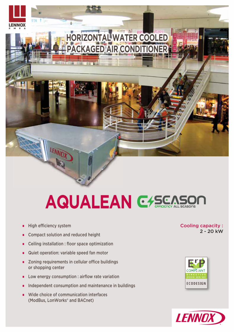
63
AQUALEAN
D I R E C T I V E 2 0 0 9 / 1 2 5 / E C
ECODESIGN
ErP
High efficiency system
Compact solution and reduced height
Ceiling installation : floor space optimization
Quiet operation: variable speed fan motor
Zoning requirements in cellular office buildings or shopping center
Low energy consumption : airflow rate variation
Independent consumption and maintenance in buildings
Wide choice of communication interfaces (ModBus, LonWorks® and BACnet)
Cooling capacity :2 - 20 kW
HORIZONTAL WATER COOLED PACKAGED AIR CONDITIONER

64
AQUALEAN2 20 kW
Main applications• Medium and light commercial buildings• Restaurants• Retail
Horizontal water cooled packaged air conditioner
High effi ciency system : Water source heat pump enabling to reach
very high effi ciency in cooling and heating modes
Variable speed direct transmission ventilation to save energy and lower operational costs
Electronic expansion valve to ensure optimized performances
Scroll /rotary compressor operating
Comfort : Each unit answers to the heating or cooling
load of the individual zone Advanced Climatic controller with accurate
operation managed by electronic expansion valves pressure transducers and temperature sensors
Compact and adaptable solution : Compact self supporting casing with very low
height to lower dropped ceilings dimension Numerous different air configurations
available Low water kit option
H
C
C
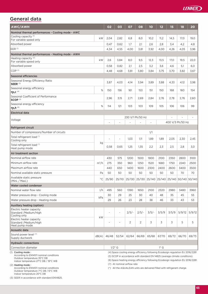
65
AWC/AWH 02 03 07 08 10 12 15 18 20
kW 2,04 2,82 6,8 8,0 10,2 11,2 14,5 17,0 19,0
0,47 0,62 1,7 2,1 2,6 2,8 3,4 4,2 4,8
4,34 4,55 4,00 3,81 3,92 4,00 4,26 4,05 3,96
kW 2,6 3,84 8,0 9,5 12,3 13,5 17,0 19,5 22,0
0,58 0,82 2,1 2,5 3,2 3,6 4,6 5,1 6,0
4,48 4,68 3,81 3,80 3,84 3,75 3,70 3,82 3,67
3,87 4,03 4,14 3,94 3,89 3,88 4,33 4,12 3,98
% 150 156 161 153 151 150 168 160 154
2,96 3,15 2,71 2,69 2,84 2,76 2,78 2,76 2,60
% 114 121 103 103 109 105 106 106 99
- - -
- - - - -
1/1
kg- - 1,03 1,11 1,89 1,89 2,05 2,30 2,45
0,58 0,65 1,25 1,35 2,2 2,3 2,5 2,8 3,0
m3/h
430 575 1200 1500 1900 2100 2350 2800 3100
275 350 960 1250 1520 1680 1750 2240 2500
440 650 1400 1600 2300 2400 2600 3400 3500
Pa 50 50 50 50 50 50 50 70 70
°C 25/90 25/110 25/130 25/130 25/140 25/140 25/140 50/140 50/140
495 560 1390 1650 2100 2320 2980 3480 3960
kPa30 29 25 30 40 48 35 45 55
29 26 23 28 38 46 33 43 53
kW
- - 2/5/- 2/5/- 3/5/- 3/5/9 3/5/9 5/9/12 5/9/12
- - 2 2 3 3 3 5 5
dB(A) 46/48 52/54 62/64 66/69 65/68 67/70 69/72 66/70 69/73
1/2" G 1" G
General data
Nominal thermal performances - Cooling mode - AWCCooling capacity (1)For variable speed onlyAbsorbed power
EER (1)
Nominal thermal performances - Heating mode - AWHHeating capacity (2)
For variable speed onlyAbsorbed power
COP (1)
Seasonal effi ciencies
Seasonal Energy Effi ciency RatioSEER (3)
Seasonal energy effi ciencyɳs,c (4)
Seasonal Coeffi cient of PerformanceSCOP (5)
Seasonal energy effi ciencyɳs,h (6)
Electrical data
Voltage230 V/1 Ph/50 Hz
400 V/3 Ph/50 Hz
Refrigerant circuit
Number of compressors/Number of circuits
Total refrigerant load (*)Cooling only
Total refrigerant load (*)Heat pump mode
Air treatment section
Nominal airfl ow rate
Minimum airfl ow rate
Maximum airfl ow rate
Nominal available static pressure
Available static pressure(Mini. / Maxi.)
Water cooled condenser
Nominal water fl ow rate l/h
Water pressure drop - Cooling mode
Water pressure drop - Heating mode
Auxiliary heating (option)Electric heater capacityStandard /Medium/HighCooling onlyElectric heater capacityStandard /Medium/HighHeat pump mode
Acoustic dataSound power level (7) Supply ductwork
Hydraulic connections
Connection diameter
(1) Cooling mode : According to EN14511 nominal conditions Outdoor temperature 35°C DB Indoor temperature 27°C DB / 19°C WB
(2) Heating mode : According to EN14511 nominal conditions Outdoor temperature 7°C DB / 6°C WB Indoor temperature 20°C DB
(3) SEER in accordance with standard EN14825.
(4) Space cooling energy effi ciency following Ecodesign regulation EU 2016/2281
(5) SCOP in accordance with standard EN 14825 (average climate conditions).
(6) Space heating energy effi ciency following Ecodesign regulation EU 2016/2281.
(7) At nominal airfl ow rate
(*) All the AQUALEAN units are delivered fi lled with refrigerant charge.

AWC/AWH 02 03 07 08 10 12 15 18 20
°C
32 / 23
21 / 15
45
16 (1)
°C
17
10 (1) 10
AWC/AWH 02 03 07 08 10 12 15 18 20
mm
1000 792 1083 1503
500 492 623 703
230 440 490 530
kg 50 55 77 80 105 110 120 160 165
BA
C
66
AQUALEAN
| Non-contractual illustrations | GC18-E_V4 |
General data
Cooling mode
Maxi. indoor air temperature (DB/WB)
Mini. indoor air temperature (DB/WB)
Maximum water inlet temperature
Minimum water inlet temperature
Heating mode
Maxi. indoor air temperature (DB) (5) 24°C if inlet water temperature < 22°C 20°C if 22°C < inlet water temperature < 25°C
Mini. indoor air temperature (DB) (5)
Maximum water inlet temperature 25°C si 17°C < temp. d'entrée d'eau < 20°C 22°C si 20°C < temp. d'entrée d'eau < 24°C
Minimum water inlet temperature
Dimensions and weights
A
B
C
Weight - Standard unit
(1) Minimum water inlet temperature = 0°C with low water temperature kit.

67
FLATAIR
D I R E C T I V E 2 0 0 9 / 1 2 5 / E C
ECODESIGN
ErP
HORIZONTAL PACKAGED AIR CONDITIONER
Reduced energy bill
Comfort
Reliability
Adaptability
Cooling capacity :6 - 34 kW
Heating capacity :6 - 29 kW
* Nominal heating conditions (EN14511) - At partial load

68
FLATAIR
6 34 kW
FAIH
FASH
| Non-contractual illustrations | GC18-E_V4 |
Main applications• Stores in urban areas• Small sizes offi ces buildings• Restaurants & bars
Horizontal packaged air conditioner
Reduced energy bill :
Optimized efficiency
at full and part load operations, thanks to variable speed compressor and EC fans in both sides
Possibility to heat or to cool without thermodynamic operation with economizer option enabling to minimize energy bill
Dynamic defrost detects icing by monitoring the diff erence between refrigerant and outside temperatures: save up to 15% on annual energy consumption
Ecodesign compliant performances (EU 2016/2281) exceeding 2021 targets for cooling mode
Adaptability : Horizontal design to be installed in false ceilings Preservation of architecture: 100% indoor
installation Packaged and split versions, adaptable to any
building confi guration Up to 30 m (length connection) between
condensing unit and air treatment unit
Comfort : Inverter compressor produces energy, continuously
adapted to building thermal needs Air quality: Variable speed technology for stabilized air
fl ow rate and accurate supply temperature Very high effi ciency fi lter option (M5+F7) off ering an
optimized indoor air quality Acoustic comfort: fans equipped with optimized blade
geometry to reduce acoustic level Variable speed fan-motor enabling noise reduction when
operating at part load capacity.
Reliability : Products manufactured according ISO 9001
quality standards Variable speed compressor: reduced number of
startings, enabling to increase units lifetime Smooth starting and reduced peak current
compared to conventional technology
Rb
A
R
Conventional unitsSet point
Tem
pera
ture
°C
Inverter units
g
2021READY
AIR COOLING PRODUCT
EU 2016/2281

69
FLATAIR FAMH/FASH+FAIH 020 035
kW 7,0 / 22,4 11,2 / 33,6
2,91 2,79
kW 6,0 / 20,0 9,5 / 28,8
3,15 3,16
4,05 4,35
% 159,0 170,9
3,06 3,10
% 119,4 120,9
kW4,5/9
15,0
m3/h1800 2800
4500 6200
dB(A)74 78
77 79
| Non-contractual illustrations | GC18-E_V4 |
General data
Nominal thermal performances - Cooling mode - Packaged unitCooling capacity (1)
(Mini/Maxi)
EER (1)
Nominal thermal performances - Heating mode - Packaged unitHeating capacity (2)
(Mini/Maxi)
COP (2)
Seasonal effi cienciesSeasonal Energy Effi ciency RatioSEER (3)
Seasonal energy effi ciencyɳs,c (4)
Seasonal Coeffi cient of PerformanceSCOP (5)
Seasonal energy effi ciencyɳs,h (6)
Auxiliary heatingElectric heater capacityStandard /Medium
High modulating electric heater
Ventilation data - Air treatment unit
Minimum airfl ow rate
Maximum airfl ow rate
Acoustic dataOutdoor sound powerStandard unit (1)
Indoor blower outlet sound powerStandard unit (1)
FLATAIR ADVANCED range only available as heat pump version
(1) Cooling mode : According to EN14511 nominal conditions Outdoor temperature 35°C DB Indoor temperature 27°C DB / 19°C WB
(2) Heating mode : According to EN14511 nominal conditions Outdoor temperature 7°C DB / 6°C WB Indoor temperature 20°C DB
(3) SEER in accordance with standard EN14825.
(4) Space cooling energy efficiency following Ecodesign regulation EU 2016/2281
(5) SCOP in accordance with standard EN 14825 (average climate conditions).
(6) Space heating energy efficiency following Ecodesign regulation EU 2016/2281.
axi ESP
600 Pa

770
195067
0
FAIH 020 FAIH 035
775 1500 99067
0
12051500
770
10601950
FASH 020 FASH 035
770
670
2050
1980 1500 1950
FAMH 020 FAMH 035
20 35
kg
135 225
220 330
340 555
70
FLATAIR ADVANCED
| Non-contractual illustrations | GC18-E_V4 |
Dimensions
Weights
Air treatment section - Indoor unit
Condensing unit - Outdoor unit
Packaged unit
Indoor unitFAIH
Outdoor unitFASH
Packaged unitFAMH

71
COMPACTAIR
D I R E C T I V E 2 0 0 9 / 1 2 5 / E C
ECODESIGN
ErP
Cooling capacity :9 - 83 kW
Heating capacity :6 - 81 kW
VERTICAL PACKAGED AIR CONDITIONER
Reduced energy bill
Comfort
Reliability
Adaptability
* Nominal heating conditions (EN14511) - At partial load

72
COMPACTAIR
9 83 kW
CASH
CAIH
| Non-contractual illustrations | GC18-E_V4 |
Main applications• Stores in urban areas• Small sizes offi ces buildings• Restaurants & bars
Vertical packaged air conditioner
Reduced energy bill :
Optimized efficiency
at full and part loads thanks to var iable speed compressor and EC fans in both sides
Possibility to heat or to cool without thermodynamic operation with economizer option enabling to minimize energy bill
Dynamic defrost detects icing by monitoring the diff erence between refrigerant and outside temperatures : save up to 15% on annual energy consumption
Ecodesign compliant performances (EU 2016/2281) exceeding 2021 targets for cooling mode
Adaptability : Vertical design, minimising the footprint Preservation of architecture: 100% indoor
installation Packaged and split versions, adaptable to any
building confi guration Up to 45 m (length connection) between
condensing unit and air treatment unit
Comfort : Inverter compressor produces energy continuously
adapted to building thermal needs Air quality: Variable speed technology for stabilized air
fl ow rate and accurate supply temperature Very high effi ciency fi lter option (M5+F7) off ering an
optimized indoor air quality Acoustic comfort: fans equipped with optimized blade
geometry to reduce acoustic level Variable speed fan-motor enabling noise reduction when
operating at part load capacity
Reliability : Products manufactured according to ISO 9001
quality standards Variable speed compressor: reduced number of
startings, enabling to increase units lifetime Smooth starting and reduced peak current
compared to conventional technology
Rb
A
R
30,5
30
29,5
29
28,5
28
27,5
27
26,5
26
25,5
Conventional units
Tem
pera
ture
°C
Inverter units
2021READY
AIR COOLING PRODUCT
EU 2016/2281

73
COMPACTAIR CAMH 025 035 045 060 075 085
kW 7,2/22,6 11,1/32,6 16,0/45,5 28,1/60,4 35,1/71,0 40,9/85,3
3,06 2,86 2,5 2,78 2,66 2,69
kW 5,8/19,6 9,5/29,5 13,9/42,2 35,4/56,2 45,3/67,7 50,9/80,8
3,42 3,03 2,96 2,99 2,77 2,79
3,60 4,15 4,35 3,85 4,00 4,05
% 140 166 174 154 160 162
3,00 3,03 2,98 3,05 3,03 2,98
% 120 121 119 122 121 119
kW10/15 15/20
20 40
m3/h1800 2800 3700 6200 6700 7500
4500 6200 7500 12500 13500 15000
dB(A)70 78 81 83 83 85
77 77 82 79 81 84
| Non-contractual illustrations | GC18-E_V4 |
General data
Nominal thermal performances - Cooling mode - Packaged unitCooling capacity (1)
(Mini/Maxi)
EER (1)
Nominal thermal performances - Heating mode - Packaged unitHeating capacity (2)
(Mini/Maxi)
COP (2)
Seasonal effi cienciesSeasonal Energy Effi ciency RatioSEER (3)
Seasonal energy effi ciencyɳs,c (4)
Seasonal Coeffi cient of PerformanceSCOP (5)
Seasonal energy effi ciencyɳs,h (6)
Auxiliary heatingElectric heater capacityStandard /High
High modulating electric heater
Ventilation data (Indoor unit)
Minimum airfl ow rate
Maximum airfl ow rate
Acoustic dataOutdoor sound powerStandard unit (1)
Indoor blower outlet sound powerStandard unit (1)
COMPACTAIR ADVANCED range only available as heat pump version
(1) Cooling mode : According to EN14511 nominal conditions Outdoor temperature 35°C DB Indoor temperature 27°C DB / 19°C WB
(2) Heating mode : According to EN14511 nominal conditions Outdoor temperature 7°C DB / 6°C WB Indoor temperature 20°C DB
(3) SEER in accordance with standard EN14825.
(4) Space cooling energy efficiency following Ecodesign regulation EU 2016/2281
(5) SCOP in accordance with standard EN 14825 (average climate conditions).
(6) Space heating energy efficiency following Ecodesign regulation EU 2016/2281.
axi ESP
600 Pa

74
CAIH 025 - 035 - 045
CASH 025 - 035 - 045
CAMH 025 - 035 - 045
CAIH 060 - 075 - 085
CASH 060 - 075 - 085
CAMH 060 - 075 - 085
836
1445895
1410
1445 895
2145
8951445
2813
895
836
2813
1410
895
2813
2145
895
COMPACTAIR ADVANCED
| Non-contractual illustrations | GC18-E_V4 |
Dimensions
Air treatment section - Indoor unit
Condensing unit - Outdoor unit
Packaged unit

75
AQUALEAN - FLATAIR ADVANCED - COMPACTAIR ADVANCED
AQUALEANAWC/AWH
FLATAIR ADVANCEDFAMH
COMPACTAIR ADVANCEDCAMH
CLIMATIC 60 eCLIMATIC
DSDS
DM
DC
| Non-contractual illustrations | GC18-E_V4 |
Con
trol
ler
inte
grat
ed to
the
unit
Rem
ote
disp
lay
Del
iver
ed w
ith th
e un
it
DC(as an option on sizes 002 & 003).
No display delivered with the unit
Opt
iona
l rem
ote
disp
lays
AVAILABLE CONTROLS PER RANGE3 diff erent remote displays are available :
REGULATION SENSORS• AQUALEAN/FLATAIR ADVANCED /COMPACTAIR ADVANCED : A return sensor is used for control. Return sensor used
to control the unit (if needed, the control with a remote ambient sensor is possible as an option).
DM 60Non available
on sizes 002 and 003.
DCFor sizes 002 and 003
DC «Comfort» display: This is a remote controller for non-technical customer. It was designed to aesthetically fit in the room and be very easy to use. The DC display allows the customer to modify the set point of the current time zone and to manage start and stop of the unit.Display unit maximum distance = 30 meters.
DM «Multi-units» display:In addition to DC features, the DM makes programming of time zones, temperature setpoints and fresh air percentage possible. It may pilot up to 8 units through only one bus.Display unit maximum distance = 500 meters.
DS «Maintenance» display: This display allows the service personal to set up all the parameters and to read up all the variables and faults. It allows to read the history of last 99 faults too.

76
AQUALEAN - FLATAIR ADVANCED - COMPACTAIR ADVANCED
AQ
UA
LEA
NA
WC
/AW
H
FLA
TAIR
A
DV
AN
CE
DFA
IH/F
ASH
/FA
MH
CO
MP
AC
TAIR
AD
VA
NC
ED
CA
IH/C
ASH
/CA
MH
| Non-contractual illustrations | GC18-E_V4 |
Auxiliary heating (*)1 or 2 steps electric heater
Modulating electric heater
RefrigerantR410A
Pressure transducers
Compressors
Scroll/MultiScroll
Tandem (1)
Inverter compressor
Compressor noise jacket (*)
Air fl ow confi guration
Horizontal supply
Up supply
Horizontal return
Supply fansDirect drive fan
Variable speed fan
Condenser fans
Direct drive fan
Variable speed fan
Variable speed centrifugal fan
Economiser (*) Motorised free-cooling/heating
CasingMain disconnect switch
Pre-coated galvanised steel (White)
Insulation (*) A1 (M0) fi re-proof
Air fi lter (*)
G2
G4
M5 + F7
Anti-corrosion protection (*)Blue fi n coated coil protection for outdoor coil
Blue fi n coated coil protection for indoor and outdoor coil
Exhaust (*) Exhaust fan
Control and communication
Dry & analogic contacts board
ModBus RS485 interface
LonWorks® FTT10 interfaceBACnet RS485 interface
ModBus & BACnet TCP/IP interface
Service display
Multi-units display
Additional control and safety
Smoke detector (*)
Remote ambient temperature sensor
CO2 control
Humidity control
3 phase detector
Hydraulic options
Water filterFlow switches (paddle one, or through differential pressure measurement)
3-way mixing valve
STANDARD EQUIPMENTS AND OPTIONS
Standard equipment
Option
(1) : 2 circuits units(2) : Size 007 to 020 : As standard on the air treatment unit(*) More details on following page.
77
AQUALEAN - FLATAIR ADVANCED - COMPACTAIR ADVANCED
| Non-contractual illustrations | GC18-E_V4 |
OptionsFresh air
• Economizer: Allows to considerably reduce the operating costs by using free-cooling at the appropriate time. In adidtion, the economizer is able to ensure that fresh air provided to the building meets the Indoor Air Quality requirement.
• Exhaust fan module: This ensures overpressure extraction in case of high level of fresh air inlet.
Indoor air quality• High effi ciency fi ltration :
AQUALEAN : Set of G4 prefi lter and F7 (ePM1) fi lter at return, operating on return air and fresh air. Adding a G4 pre-fi lter before the F7 (ePM1) fi lter reduces excessive replacement of this one. FLATAIR & COMPACTAIR ADVANCED : Set of M5 (ePM10) prefi lter and F7 (ePM1) fi lter at return, operating on return air and fresh air. Adding a M5 (ePM10) pre-fi lter before the F7 (ePM1) fi lter reduces excessive replacement of this one.
• Analog dirty filter sensor: A differential pressure sensor measures the pressure drop across the filters and coil to allow preventive filter change, thus reducing energy consumption and improving air quality.
Auxiliary heating• Electrical heater:
Standard (S), Medium (M) and High (H) capacity heaters. Available with steps or modulating control.
Electrical and safety• A1 insulation air treatment unit:
A1 (M0) rock or glass whool insulation as an option.
• Smoke detector: The optical head of the smoke detector can detect any type of smoke. When this occurs the unit will stop operating, the return air damper will close fully and the fresh air damper will open fully.
• Compressor electrical protection: This device prevents the compressor from starting if the phases are reversed (3-phase units only).
Refrigeration options• Long refrigerant piping:
Allows up to 30 m (FLATAIR ADVANCED) and 45 m (COMPACTAIR ADVANCED) piping between the internal and external units.
• Refrigerant pre-charged: Split condenser supplied with factory fi lled refrigerant pre-charge. Includes shut off service valves, on liquid and gas loop sides.
Other options• Low noise:
Reduce acoustic level thanks to compressor jackets.
• Precoated coil: Outdoor or indoor coils anticorrosion treatment. Particularly recommended in salin or polluted environment.

78
FIC/FIH/FIX10 28 kW
FIX/FIC/FIH 10 10 12 15 20 25 30
kW 9,7 12,1 15,0 19,5 23,5 27,0
kW10,0 12,5 15,5 20,5 25,0 27,9
3/6/- 3/6/9 4,5/6/9 7,5/9/12
m3/h
1500 1650 2410 3090 3455 3695
2140 2040 3170 4500 5470 5060
2350 2300 3575 4850 5750 5500
Pa 120 110 160 200 240 180
dB(A) 72 76 80 84 83
A B
C
FIX/FIC/FIH 10 12 15 20 25 30
A
mm
430 430 500 620 775 775
B 1250 1250 1300 1450 1500 1500
C 500 500 595 595 645 645
kg 58 58 85 109 121 131
| Non-contractual illustrations | GC18-E_V4 |
Main applications• Stores in urban area• Small size offi ce buildings• Bank offi ces• Restaurant & Bars
Air treatment unit
(1) : Ambient air temperature : 27 °C DB, 19 °C WB Outdoor air temperature : 35 °C DB, 24 °C WB.(2) : Ambient air temperature : 20°C DB, 12°C WB Outdoor air temperature : 7°C DB, 6°C WB.
(3) : EUROVENT conditions.
Cooling mode
Net cooling capacity (1)
Heating mode
Net heating capacity (2)
Electric heater capacity (option)Standard/Medium/High
Air treatment section
Minimum airfl ow rate
Nominal airfl ow rate
Maximum airfl ow rate
Maximum available static pressure
Acoustic data
Global sound power level (3)
Weight
Dimensions

79
CIC/CIH19 135 kW
CIC/CIH 20S 25S 30S 35S 40S 45D 55D 70D 85D 100D 120D 140D
19,9 24,2 27,9 36,5 41,9 48,7 57,3 72,4 86,0 103,9 116,2 140,6
19,5 23,5 27,0 35,5 40,5 46,5 55,5 69,5 82,0 100,0 111,0 135,0
19,5 25 28,5 36 40 49,5 56,5 72,5 80 108 118 137
10 10 10 15 15 15 20 20 20 27 27 27
15 15 15 20 20 20 27 27 27 40 40 40
20 20 20 27 27 27 40 40 40 50 50 50
31 38 40 56 61 66 91 105 113 171 183 192
3150 4250 4650 6200 6950 7950 9950 12450 14000 17350 19300 21000
4100 5500 6000 8050 9050 9750 12850 15090 16725 22450 24950 24750
685 672 650 729 833 812 747 711 680 812 784 828
75 82 82 82 85 86 80 85 87 85 87 89
BA
C
CIC/CIH 20S
25S
30S
35S
40S
45D
55D
70D
85D
100D
120D
140D
A 1195 1445 2250 2900
B 840 960 960 1140
C 645 735 735 1140
108 111 115 150 160 170 242 259 276 470 480 490
| Non-contractual illustrations | GC18-E_V4 |
Main applications• Retail premises in urban area• Shopping malls• Industry
Air treatment unit
Dimensions
(1) Standard unit - Heat pump version
(1) Evaporating temperature = 7 °C / Ambiant air temperature = 35 °C(2) Condensing temperature = 50 °C / Ambiant air temperature = 7 °C BS/6 °C BH
Cooling mode - CIC
Gross cooling capacity (1)kW
Net cooling capacity (1)
Heating mode - CIH
Net heating capacity (2)
kWElectrical heater capacity (option)Standard/Medium/High
Hot water coil capacity (2)
Ventilation
Minimum airfl ow ratem3/h
Maximum airfl ow rate
Maximum available static pressure Pa
Acoustic data (3)
Blower outlet sound power level (Lw)
mm
Operating weight (1) kg

80
FSC/FSH 10 10 12 15 20 25 30
kW9,7 12,1 15,0 19,5 23,5 27,0
3,7 5,2 5,9 8,0 9,6 11,7
kW10,0 12,5 15,5 20,5 25,0 27,9
3,2 4,5 5,4 6,8 8,7 9,9
V/Ph/Hz 230/1/50+N 400/3+N/50
1/1
kg2,14 2,57 3,55 4,46 5,38 6,15
2,5 2,93 4,0 4,9 6,3 7,0
m3/h
2350 2400 3740 4095 4760 5000
2970 2890 4250 5150 5600 5400
3500 3400 4500 5650 6000 5850
Pa 100 90 120 150 160 100
dB(A) 77 82 86 81 81
FSC/FSH 10 12 15 20 25 30
A 1250 1300 1450 1500
B 820 830 900 1025
C 500 595 595 645
175 179 255 273 327 343
FSC/FSH10 28 kW
BA
C
| Non-contractual illustrations | GC18-E_V4 |
Main applications• Stores in urban area• Small size offi ce buildings• Bank offi ces• Restaurant & Bars
Horizontal ductable condensing unit
Cooling mode
Net cooling capacity (1)
Absorbed power
Heating mode
Net heating capacity (2)
Absorbed power
Electrical data
Electrical supply
Refrigerant circuit
Number of compressors/Number of circuits
Total refrigerant charge - Cooling only
Total refrigerant charge - Heat pump
Thermodynamic section (FSC/FSH)
Minimum airfl ow rate
Nominal airfl ow rate
Maximum airfl ow rate
Maximum available static pressure
Acoustic data
Global sound power level (3)
(1) : Ambient air temperature : 27 °C DB, 19 °C WB Outdoor air temperature : 35 °C DB, 24 °C WB
(2) : Ambient air temperature : 20°C DB, 12°C WB Outdoor air temperature : 7°C DB, 6°C WB.
(3) : EUROVENT conditions.
Dimensions
mm
Weight kg

81
CSC/CSH20 100 kW
CSC/CSH 20S 25S 30S 35S 40S 45D 55D 70D 85D 100D
kW18,8 23,1 26,0 33,8 38,8 43,5 54,0 66,2 78,0 96,8
7,3 9,3 11,0 13,7 15,9 18,9 21,5 27,8 32,6 40,7
kW19,7 25,9 30,4 37,2 43,7 52,0 61,0 72,8 86,0 105,1
6,6 8,6 10,7 12,4 14,0 17,4 20,3 24,8 28,5 35,4
1/1
kg 4,3/4,5
5,4/5,5
6,0/6,2
7,8/8,0
9,0/9,3
10,3/10,6
12,5/12,6
15,5/16,0
18,5/19,1
23,0/25,2
m3/h 7600 8500 10000 12000 11700 14000 20000 21000 22000 15500 + 11700
Pa 178 223 272 209 205 237 299 272 277 239 + 201
dB(A) 82 85 86 85 85 88 87 88 89 92
CSC/CSH 20S 25S 30S 35S 40S 45D 55D 70D 85D 100D
A 1194 1445 2251 2 x 1450
B 745 870 870 870
262 295 302 357 370 448 529 554 586 2 x 435
BA
1410
A
A B
1410
| Non-contractual illustrations | GC18-E_V4 |
Main applications• Retail premises in urban area• Shopping malls• Industry
Vertical ductable condensing unit
Cooling mode
Net cooling capacity (1)
Absorbed power (1)
Heating mode
Net heating capacity (1)
Absorbed power (1)
Electrical data
Electrical supply 400V/3Ph/50Hz
Refrigeration circuit
Number of compressors / Number of circuits
Total refrigerant loadCooling only / Heat pump
Ventilation data
Nominal airfl ow rate
Maximum available static pressure
Acoustic data
Blower outlet sound power level (Lw)
(1) EUROVENT conditions data Cooling : Outdoor temperature = 35°C DB Entering coil temperature 27°C DB / 19°C WB
Heating : Outdoor temperature = 7°C DB / 6°C WB Indoor temperature = 20°C DB
Dimensions
mm
Operating weight (1) kg
Sizes 20S to 85D Sizes 100DSlave section
Master section
(1) Standard unit - Heat pump version

82
ASC/ASH20 230 kW
ASC/ASH 020S 025S 030S 035S 040S 045D 055D
kW 19,7 24,7 28,4 36,1 42 49,4 56,7
3,06 3,05 2,95 3,03 2,98 3,05 2,94
kW 19,8 25,0 28,6 36,0 40,2 50,1 57,1
3,20 3,21 3,12 3,24 2,98 3,21 3,1
1/1 1/1 1/1 1/1 1/1 2/2 2/2
1 1 1 1 1 2 2
kW 8,55 10,8 12,5 16,4 17,7 21,6 25
dB(A) 76 78 81 80 81 81 84
ASC/ASH 070D 085D 100D 120D 140D 200D 230D
kW 72,1 83,9 104 115 141 197 228
3,04 2,96 3,03 3,1 3,05 3,11 3,06
kW 71,9 80,3 105 114 137 191 218
3,24 3,1 3,24 3,2 3,13 3,19 3,06
2/2 2/2 3/2 3/2 3/2 4/2 4/2
2 2 2 2 2 2 2
kW 32,8 35,5 45,6 48,7 59,9 83,0 96,2
dB(A) 83 84 87 87 90 89 82
ASC/ASH 20S
25S
30S
35S
40S
45D
55D
70D
85D
100D
120D
140D
200D
230D
A
mm
1195 1195 1960 2250 2250
B 660 980 1195 1420 2300
C 1375 1635 1635 2155 2250
kg 168 219 221 239 258 452 463 499 537 748 828 932 1684 1704 AB
C
| Non-contractual illustrations | GC18-E_V4 |
Main applications• Retail premises in urban area• Shopping malls• Industry
Air cooled condensing unit
Dimensions
(1) Standard unit - Heat pump version
(1) Température d'évaporation = 7 °C / Température ambiante = 35 °C(2) Température de condensation = 50 °C / Température ambiante = 7 °C BS/6 °C BH(3) Données aux conditions Eurovent
Operating weight (1)
Cooling mode - ASCCooling capacity (1)
EER (1)
Heating mode - ASHHeating capacity (2)
COP (2)
Refrigeration circuitNumber of compressors / Number of circuits
Capacity steps
Electrical dataVoltage 400 V/3-Ph/50 Hz
Maximum absorbed power
Acoustic dataSound power level (3)
Cooling mode - ASCCooling capacity (1)
EER (1)
Heating mode - ASHHeating capacity (2)
COP (2)
Refrigeration circuitNumber of compressors / Number of circuits
Capacity steps
Electrical dataVoltage 400 V/3-Ph/50 Hz
Maximum absorbed power
Acoustic dataSound power level (3)

83
ASC/ASH - FSC/FSH - CSC/CSH
FSC/FSH CSC/CSH & ASC/ASH
CLIMATIC 40 CLIMATIC 60
DC
DC
DS
DM
| Non-contractual illustrations | GC18-E_V4 |
Con
trol
ler
inte
grat
ed to
the
unit
Rem
ote
disp
lay
Del
iver
ed w
ith th
e un
it
DC
Opt
iona
l rem
ote
disp
lays
No display option
AVAILABLE CONTROLS PER RANGE3 diff erent remote displays are available :
REGULATION SENSORS• CSC/CSH/ASC/ASH : A return sensor is used for control. Return sensor used to control the unit (if needed, the control
with a remote ambient sensor is possible as an option).
No display delivered with the unit
DC «Comfort» display: This is a remote controller for non-technical customer. It was designed to aesthetically fit in the room and be very easy to use. The DC display allows the customer to modify the set point of the current time zone and to manage start and stop of the unit.
Display unit maximum distance = 30 meters.
DM «Multi-units» display:In addition to DC features, the DM makes programming of time zones, temperature setpoints and fresh air percentage possible. It may pilot up to 8 units through only one bus.
Display unit maximum distance = 500 meters.
DS «Maintenance» display: This display allows the service personal to set up all the parameters and to read up all the variables and faults. It allows to read the history of last 99 faults too.

84 | Non-contractual illustrations | GC18-E_V4 |

85
|eCOMFORT20 190 kW 87
ECOLEAN40 200 kW 93
|AQUA4
50 320 kW 99
|NEOSYS200 1000 kW 103
|HYDROLEAN20 160 kW 111
MWC/MRC180 720 kW 117
• 122
|FC/FI NEOSTAR20 1200 kW 124
V-KING50 2000 kW 127
|NEOSTAR18 1240 kW 130
MXW50 1670 kW 132
| Non-contractual illustrations | GC18-E_V4 |
Chillers and heat pumps
Air cooled condensers and dry-coolers
Air cooled chiller/Heat pump
Polyvalent air cooled heat pump
Air cooled chiller/Heat pump
Water cooled chiller & Heat pump
Standard equipments and options
Dry-cooler
Condenser

86 | Non-contractual illustrations | GC18-E_V4 |
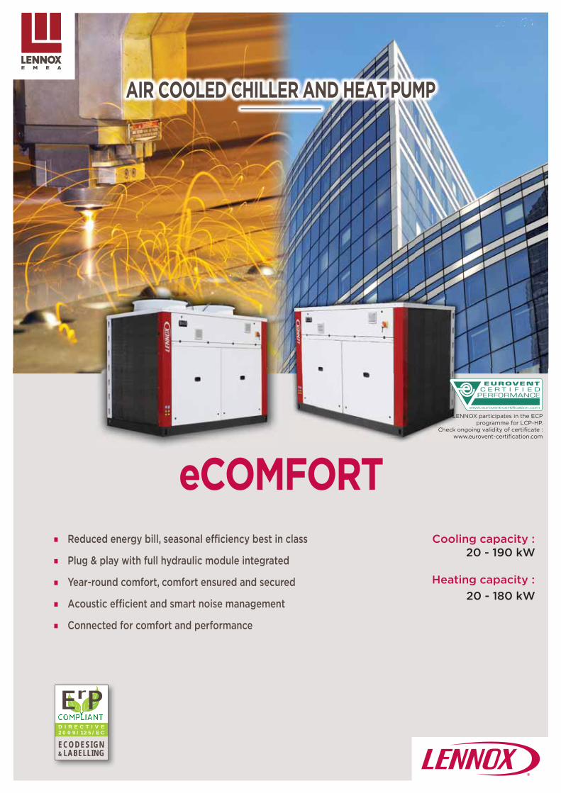
87
eCOMFORT
D I R E C T I V E 2 0 0 9 / 1 2 5 / E C
ECODESIGN& LABELLING
ErP
AIR COOLED CHILLER AND HEAT PUMP
Reduced energy bill, seasonal effi ciency best in class
Plug & play with full hydraulic module integrated
Year-round comfort, comfort ensured and secured
Acoustic effi cient and smart noise management
Connected for comfort and performance
Cooling capacity :20 - 190 kW
Heating capacity :20 - 180 kW
LENNOX participates in the ECP programme for LCP-HP.
Check ongoing validity of certifi cate :www.eurovent-certifi cation.com

88
D I R E C T I V E 2 0 0 9 / 1 2 5 / E C
ECODESIGN& LABELLING
ErP
eCOMFORT20 190 kW
2021READY
COMFORTCOOLING
n°2016/2281
| Non-contractual illustrations | GC18-E_V4 |
Main applications• Small size offi ce buildings• Hotels• Hospitals• Industry process
Air cooled chiller/Heat pump
CONTROL LennoxHydroControl is the smartest solution for hydronic systems, it manages and coordinates cooling and heating production (chiller/heat-pump units) through up to 32 fancoils. It ensures customer comfort, providing important energy savings through building zoning, time scheduling and set points control. This function is uniqUE compared to the other standard stand-alone systems.
Comfort applications
Reduced energy bill : Energy cost saving thanks to high effi ciencies all year
round, high SEER and SCOP (A+ Class) eDrive reduces operating cost thanks to inverter on
water pump Free hot sanitary water up to 70°C, thanks to partial
heat recovery
Plug & Cool/Heat : Full hydraulic module integrated with single or dual
pump with low or high external static pressure High content water tank, up to 400 liters Low ambient operation in heating mode down to
-15°C Modulating immersion heater for full capacity in
heating mode down to -15°C
Connectivity for comfort : Packaged smart system connectivity for chiller
or heat pump with fan coils and AHU installation (Lennoxhydrocontrol)w
Acoustic effi ciency : Low and adjustable noise level thanks to Active
Acoustic Attenuation system
RR
P
CC
AA

89
eCOMFORT
D I R E C T I V E 2 0 0 9 / 1 2 5 / E C
ECODESIGN& LABELLING
ErP
&& LLABABELELLILINGNG
2021READY
PROCESS COOLINGHIGH TEMP.
EU2016/2281
| Non-contractual illustrations | GC18-E_V4 |
Smartphones & tabletsapplications
Customer services portal
Alarm manager
LENNOX Chillers
Owner website
SUPERVISION LennoxCloud is the remote supervision system of LENNOX units. It’s a uniqUE system for multi units located in diff erent installations.Through LennoxCloud, the unit can be remotely controlled, adjusted, or diagnosed by our experts.LennoxCloud can check (live data trends), optimize (store data analysis) and troubleshoot (alarm/alert reports) customer units.LennoxCloud allows signifi cant energy savings optimizing performances during all the unit’s life cycle.
Reduced energy bill : Reduced energy cost thanks to high SEPR eDrive reduces operating cost thanks to inverter on
water pump Free cooling kit managed by the unit
Serviceability : Connectivity for performance, LennoxCould
allows signifi cant energy savings by avoiding performance drift
Very low refrigerant load and high corrosion resistance (micro channel coil)
Reliability : Low ambient, winter cooling operation down to -20°C
(EC fan) Accurate operation, thanks to the combination of multi-
scroll compressors, electronic expansion valve and buff er tank
Redundancy with 2 circuits from 100 kW to 180 kW Dual pump mounted in parallel with low or high
external static pressure
Plug & Cool : Full hydraulic module integrated High content water tank up to 400 liters Large range of options : electric energy meter,
power factor correction and softstarterRR
SS
RR
Process cooling applications
P

90
eCOMFORT 020S 025S 030S 035S 040S 045S 055S 060S 070S 080S
kW 20 24 31 36 39 45 54 60 68 81
3,31 3,05 2,77 2,94 2,94 2,92 3,02 2,99 2,96 3,05
A B C B B C B B B B
4,45 4,41 4,11 4,16 4,17 4,05 4,35 4,15 4,30 4,25
GAC/GAH
4,20/4,45
4,23/4,38
4,10/4,10
4,13/4,10
4,18/4,18
4,10/4,10
4,28/4,33
4,18/4,10
4,28/4,30
4,25/4,28
165% /175%
166% /172%
161% /161%
162% /161%
164% /164%
161% /161%
168% /170%
164% /161%
168% /169%
167% /168%
5,64/5,69
5,80/5,70
5,39/5,31
5,41/5,32
5,44/5,44
5,28/5,20
5,62/5,55
5,36/5,28
5,39/5,40
5,30/5,29
3,33/3,39
3,53/3,52
3,54/3,51
3,64/3,62
3,44/3,46
3,46/3,44
3,73/3,72
3,63/3,60
3,65/3,68
3,58/3,60
kW 19,8 24,5 31,9 36,7 39,2 44,6 53,6 61,3 67,6 79,3
3,0 3,0 3,0 3,0 3,0 3,0 3,0 3,01 3,11 3,06
B B B B B B B B B B
3,45 3,28 3,23 3,23 3,23 3,23 3,28 3,23 3,45 3,33
135% 128% 126% 126% 126% 126% 128% 126% 135% 130%
A+
1 / 2
0-50-100%
kg 3,3/7,0
3,3/6,1
4,4/8,3
4,6/7,7
4,8/9,4
4,8/9,6
7,0/13,5
8,0/17,0
8,5/18,4
9,5/18,4
m3/h 3,47 4,24 5,47 6,36 6,92 7,85 9,45 10,56 11,99 14,26
kPa 17 25 27 36 30 39 33 40 18 24
1 1/2" 2"
eCOMFORT
| Non-contractual illustrations | GC18-E_V4 |
General data - Standard version
Cooling mode - GACCooling capacity (1)
EER (1)
Eurovent energy class (1)
Full load operation
ESEER (2)
Seasonal Energy Effi ciency Ratio (3)
SEER
Seasonal energy effi ciency (4)
ɳs,c
Seasonal Energy Performance Ratio (5)
SEPR - High temperature (7°C)
Seasonal Energy Performance Ratio (6)
SEPR - Medium temperature (-8°C)
Heating mode - GAHHeating capacity (1)
COP (1)
Eurovent energy class (1)
Full load operation
Seasonal Coeffi cient of Performance (7)
SCOP
Seasonal energy effi ciency (8)
ɳs,h
Seasonal energy effi ciency class (9)
Electrical data
Voltage 400 V/3 Ph/50 Hz
Refrigeration circuitNumber of circuits / Number of compressors(cooling only/heat pump unit)
Evaporator type Brazed plate heat exchanger
Capacity steps
Total refrigerant load (cooling only/heat pump unit)
Pressure dropNominal water fl ow rate
Pressure drop
Hydraulic connection
Type Threaded - Male Victaulic or welded
Diameter
Check ongoing validity of certifi cate :eurovent-certifi cation.com
Com
fort
appl
icat
ions
Com
fort
appl
icat
ions
Proc
ess
appl
icat
ions
(1) EUROVENT certifi ed data, in accordance with standard EN 14511 :
Cooling mode : Evaporator water temperature = 12/7°C Outdoor air temperature = 35°C
Heating mode : Condenser water temperature = 40/45°C Outdoor air temperature = 7°C
(2) ESEER following Eurovent calculation method, in accordance with standard EN 14511
(3) SEER in accordance with standard EN 14825.
(4) Following ecodesign regulation EU 2016/2281 on space cooling, normalized leaving water temperature at 7°C, in accordance with standard EN 14825.
(5) Following ecodesign regulation EU 2016/2281 on process cooling units, normalized leaving water temperature at 7°C, in accordance with standard EN 14825.
(6) Following ecodesign regulation EU 2015/1095 on process cooling chillers, normalized leaving water temperature at -8°C, in accordance with standard EN 14825
(7) SCOP in accordance with standard EN 14825. Heating mode performance is defi ned for average climate conditions.
(8) Following ecodesign regulation EU 813/2013 on space heaters, normalized leaving water temperature at 7°C, in accordance with standard EN 14825, average climate conditions.
(9) Following energy labelling regulation EU 811/2013 on space heaters.

91
eCOMFORT 090S 110S 125S 110D 125D 140D 160D 185D
kW 91 106 120 105 121 137 159 181
2,98 3,15 2,95 2,80 2,90 2,95 2,95 2,91
B A B C B B B B
4,37 4,00 4,00 4,42 4,00 4,13 4,19 4,00
GAC/GAH
4,33/4,45
4,13/4,10
4,15/4,10
4,30/4,43
4,13/4,10
4,23/4,18
4,25/4,23 4,10
170% /175%
162% /161%
163% /161%
169% /174%
162% /161%
166% /164%
167% /166% 161%
5,45/5,48
5,04/5,05
5,06/5,04
5,58/5,64
5,00/4,98
5,08/5,05
5,15/5,12
5,01/4,98
3,56/3,59
3,33/3,36
3,38/3,39
3,78/3,83
3,39/3,39
3,49/3,48
3,54/3,53
3,39/3,39
kW 91,2 103,4 118,1 106,3 121,1 135,8 157,2 174,5
3,01 3,03 3,0 3,12 3,02 3,12 3,06 3,0
B B B B B B B B
3,75 3,40 3,35 3,65 3,25 3,38 3,40 3,25
147% 133% 131% 143% 127% 132% 133% 127%
A+
1 / 3 2 / 2+2 2 / 2+2
0-33-66-100% 0-25-50-75-100% 0-25-50-75-100%0-20-40-60-80-100%
kg 12,5/23,5
12,5/25,5
14,0/26,0
13,0/27,6
13,6/29,0
16,0/35,0
16,6/37,0
16,8/38,0
m3/h 15,75 18,40 21,10 18,21 21,25 23,94 27,94 31,91
kPa 29 25 32 42 56 46 61 58
2 1/2" 3"
eCOMFORT
| Non-contractual illustrations | GC18-E_V4 |
General data - Standard version
Cooling mode - GACCooling capacity (1)
EER (1)
Eurovent energy class (1)
Full load operation
ESEER (2)
Seasonal Energy Effi ciency Ratio (3)
SEER
Seasonal energy effi ciency (4)
ɳs,c
Seasonal Energy Performance Ratio (5)
SEPR - High temperature (7°C)
Seasonal Energy Performance Ratio (6)
SEPR - Medium temperature (-8°C)
Heating mode - GAHHeating capacity (1)
COP (1)
Eurovent energy class (1)
Full load operation
Seasonal Coeffi cient of Performance (7)
SCOP
Seasonal energy effi ciency (8)
ɳs,h
Seasonal energy effi ciency class (9)
Electrical data
Voltage 400 V/3 Ph/50 Hz
Refrigeration circuitNumber of circuits / Number of compressors(cooling only/heat pump unit)
Evaporator type Brazed plate heat exchanger
Capacity steps
Total refrigerant load (cooling only/heat pump unit)
Pressure drop
Nominal water fl ow rate
Pressure drop
Hydraulic connection
Type Victaulic connection
Diameter
Check ongoing validity of certifi cate :eurovent-certifi cation.com
Com
fort
appl
icat
ions
Com
fort
appl
icat
ions
Proc
ess
appl
icat
ions
(1) EUROVENT certifi ed data, in accordance with standard EN 14511 :
Cooling mode : Evaporator water temperature = 12/7°C Outdoor air temperature = 35°C
Heating mode : Condenser water temperature = 40/45°C Outdoor air temperature = 7°C
(2) ESEER following Eurovent calculation method, in accordance with standard EN 14511
(3) SEER in accordance with standard EN 14825.
(4) Following ecodesign regulation EU 2016/2281 on space cooling, normalized leaving water temperature at 7°C, in accordance with standard EN 14825.
(5) Following ecodesign regulation EU 2016/2281 on process cooling units, normalized leaving water temperature at 7°C, in accordance with standard EN 14825.
(6) Following ecodesign regulation EU 2015/1095 on process cooling chillers, normalized leaving water temperature at -8°C, in accordance with standard EN 14825
(7) SCOP in accordance with standard EN 14825. Heating mode performance is defi ned for average climate conditions.
(8) Following ecodesign regulation EU 813/2013 on space heaters, normalized leaving water temperature at 7°C, in accordance with standard EN 14825, average climate conditions.
(9) Following energy labelling regulation EU 811/2013 on space heaters.

GAC/GAH GAC GAH GAC/GAH
020S-045S
055S-080S
090S-125S
90S-125S
110D-125D
140D-185D
A 1125 2250 2250 2250 2250 2250
B 1320 1320 1320 1740 1740 2650
C 1540 1540 1815 1815 1815 1815
D 1790 1790 2065 2065 2065 2065
eCOMFORT 020S 025S 030S 035S 040S 045S 055S 060S 070S 080S
GACkg
312 319 342 366 371 386 602 627 657 706
GAH 335 341 370 394 400 421 645 683 715 773
eCOMFORT 090S 110S 125S 110D 125D 140D 160D 185D
GACkg
876 892 892 989 1000 1401 1508 1575
GAH 927 995 995 1061 1073 1483 1592 1663
eCOMFORT
AAA
BB
DCD
BA
C
B
A
C
B
D
B
A
eCOMFORT 020S 025S 030S 035S 040S 045S 055S 060S 070S 080S
SLN (1)
dB(A)70 72 72 72 75,5 74,6 77,5 78,5 79,3 80,3
STD (2) 74 75,6 75,6 76,4 79,2 78,4 80,9 81,8 82,5 83,8
eCOMFORT
°C
+48
-15
+20 +55
+20
eCOMFORT 090S 110S 125S 110D 125D 140D 160D 185D
SLN (1)
dB(A)80 81,1 82,1 80,5 81,5 82,3 83,3 83,7
STD (2) 83,5 85,6 86,3 84,0 85,8 86,4 86,8 87,7
92 | Non-contractual illustrations | GC18-E_V4 |
Dimensions
Operating limits
Acoustic data
Standard unit Unit with variable airfl ow control by optional EC fans
With standard fan
With EC fan
Weights (operating weights)
Sound power level (4)
Cooling mode Heating mode
Maximum outside air temperature +30 (option)/+20 (standard)
Minimum outside air temperature -20 (option)/+5 (standard)
Maximum outlet water temperature
Minimum outlet water temperature -12 (option)/+5 (standard)
Acoustic data
Sound power level (4)

93
ECOLEAN
D I R E C T I V E 2 0 0 9 / 1 2 5 / E C
ECODESIGN& LABELLING
ErP
AIR COOLED CHILLER AND HEAT PUMP
Plug and play, integrated hydraulic module
Small footprint, compact for indoor or outdoor installation
Quiet, "best in class" acoustic performance
Cooling capacity: 40 - 200 kW
Heating capacity:47 - 205 kW
LENNOX participates in the ECP programme for LCP-HP.
Check ongoing validity of certifi cate :www.eurovent-certifi cation.com

94
ECOLEAN40 200 kW
| Non-contractual illustrations | GC18-E_V4 |
Main applications• Small size offi ce buildings• Residential buildings• Hotels• Hospitals• Industry
Air cooled chiller/Heat pump
PLUG AND PLAY, INTEGRATED HYDRAULIC MODULE :
Very compact integral hydraulic equipment inside the unit :
. With pum (HY version) . With pump and water tank (HN version)
SMALL FOOTPRINT, COMPACT FOR INDOOR OR OUTDOOR INSTALLATION :
Mainly for outdoor installation, 75 Pa available static pressure (S version)
Suited for indoor installation where high static pressure is required, from 75 to 250 Pa (F version)
eDRIVE, INVERTER ON WATER PUMP :
Up to 75% cost saving on pump energy consumption
Electronically adjusted water fl ow rate
QUIET, "BEST IN CLASS" ACOUSTIC PERFORMANCE :
- 7 dB(A) average noise level reduction compared to traditional unit (LN version)
- 10 dB(A) average noise level reduction compared to traditional unit (SLN version)
P
SC
e
Q"

95
EAC/EAR 0472 0552 0672 0812 1003 1103
kW 44,1 50,7 63,4 75,4 88,2 102
2,9 2,79 2,83 2,82 2,83 2,9
3,91 3,87 3,86 3,96 4,19 3,97
EAC/EAR
3,88/3,86
3,84/3,83
3,85/3,84
3,83/3,83
3,92/3,91
3,85/3,84
152%/151%
151%/150%
151% / 150%
150% / 150%
154% / 154%
151% / 151%
5,25/5,40
5,18/5,32
4,97/5,03
4,97/4,95
5,33/5,29
5,03/5,05
3,32/3,70
3,44/3,93
3,36/3,71
3,37/3,65
3,63/3,66
3,45/3,46
kW 47,8 54,7 68,0 75,7 95 108
3,00 2,94 3,00 2,92 3,05 3,00
3,23
126%
A+
EAC/EAR 1203 1303 1403 1604 1804 2104
kW 112 126 139 149 174 199
2,79 2,86 2,87 2,76 2,9 2,8
3,83 3,87 3,98 4,02 3,98 3,76
EAC/EAR
3,82/3,82
3,80/3,80
3,89/3,86
3,92/3,89
3,89/3,92
3,81/3,80
150% /150%
149% /149%
153%/151%
154%/153%
153%/154%
149% / 149%
4,83/4,72
4,82/4,80
4,95/4,92
4,90/4,81
5,23/4,89
4,80/4,70
3,33/3,34
3,58/3,30
3,65/3,41
3,63/3,37
3,69/3,43
3,66/3,17
kW 118 130 143 159 180 205
3,00 2,92 2,97 3,00 2,95 2,85
3,23
126%
A+
| Non-contractual illustrations | GC18-E_V4 |
General data - Standard version
Cooling modeCooling capacity (1)
EER (1)
ESEER (2)
Seasonal Energy Effi ciency Ratio (3)
SEER
Seasonal energy effi ciency (4)
ɳs,c
Seasonal Energy Performance Ratio (5)
SEPR - High temperature (7°C)
Seasonal Energy Performance Ratio (6)
SEPR - Medium temperature (-8°C)
Heating modeHeating capacity (1)
COP (1)
Seasonal Coeffi cient of Performance (7)
SCOP
Seasonal energy effi ciency (8)
ɳs,h
Seasonal energy effi ciency class (9)
Check ongoing validity of certifi cate :eurovent-certifi cation.com
Com
fort
appl
icat
ions
Com
fort
appl
icat
ions
Com
fort
appl
icat
ions
Com
fort
appl
icat
ions
Proc
ess
appl
icat
ions
Proc
ess
appl
icat
ions
Cooling modeCooling capacity (1)
EER (1)
ESEER (2)
Seasonal Energy Effi ciency Ratio (3)
SEER
Seasonal energy effi ciency (4)
ɳs,c
Seasonal Energy Performance Ratio (5)
SEPR - High temperature (7°C)
Seasonal Energy Performance Ratio (6)
SEPR - Medium temperature (-8°C)
Heating modeHeating capacity (1)
COP (1)
Seasonal Coeffi cient of Performance (7)
SCOP
Seasonal energy effi ciency (8)
ɳs,h
Seasonal energy effi ciency class (9)
(1) EUROVENT certifi ed data, in accordance with standard EN 14511 :
Cooling mode : Evaporator water temperature = 12/7°C Outdoor air temperature = 35°C
Heating mode : Condenser water temperature = 40/45°C Outdoor air temperature = 7°C
(2) ESEER following Eurovent calculation method, in accordance with standard EN 14511
(3) SEER in accordance with standard EN 14825.
(4) Following ecodesign regulation EU 2016/2281 on space cooling, normalized leaving water temperature at 7°C, in accordance with standard EN 14825.
(5) Following ecodesign regulation EU 2016/2281 on process cooling units, normalized leaving water temperature at 7°C, in accordance with standard EN 14825.
(6) Following ecodesign regulation EU 2015/1095 on process cooling chillers, normalized leaving water temperature at -8°C, in accordance with standard EN 14825
(7) SCOP in accordance with standard EN 14825. Heating mode performance is defi ned for average climate conditions.
(8) Following ecodesign regulation EU 813/2013 on space heaters, normalized leaving water temperature at 7°C, in accordance with standard EN 14825, average climate conditions.
(9) Following energy labelling regulation EU 811/2013 on space heaters.

96
ECOLEAN
EAC/EAR 0472 0552 0672 0812
LN (2)
dB(A)74/43 73/42 74/43 75/44
STD 79/47 79/47 80/48 81/49
EAC/EAR 1003 1103 1203 1303 1403 1604 1804 2104
SLN (2)
dB(A)
72/40 75/43 76/44 78/46 78/46 76/44 77/45 80/48
LN (2) 75/43 76/44 79/47 81/49 81/49 78/46 81/49 83/51
STD 80/48 82/50 85/53 87/55 87/55 85/53 87/55 90/57
ECOLEAN0472 0812 1003 2104
°C
+ 48 + 23
-12
+ 14 +50
+25
EAC/EAR 0472 0552 0672 0812 1003 1103 1203 1303 1403 1604 1804 2104
R410A
1 2
2 3 4
2 3 4
kg 11/12,5
12,2/13,5
15,5/16,0
19,5/19,3
23,5/23,3
26/28
27/29,5
30/32,2
33,7/35,5
36,2/40
45/52
47/54
m3/h 7,59 8,72 10,9 12,98 15,2 17,6 19,2 21,6 23,9 25,7 29,9 34,2
kPa32 34 40 47 35 34 40 48 48 43 48 64
50 57 71 87 43 47 57 69 76 61 73 95
2" 2 1/2" 3"
| Non-contractual illustrations | GC18-E_V4 |
General data - Standard versionCheck ongoing validity of certifi cate :
eurovent-certifi cation.com
Sound power level /Sound pressure level (1)
(1) Sound power level and sound pressure level at 10 m from the unit, in free fi eld, conformity with ISO3744 norm
(2) Maximum sound power level only if "Quiet" mode is selected. If "Auto Quiet" mode is selected, the unit may operate the high fan speed to work at full load and avoid compressor unloading in case of very high or very low ambient temperatures.
Sound power level /Sound pressure level (1)
Operating limits
Acoustic data
Cooling mode Heating mode
Maximum outside air temperature
Minimum outside air temperature -15 (option)/+6 (standard)
Maximum outlet water temperature
Minimum outlet water temperature -10 (option)/+5 (standard)
Electrical dataVoltage 400 V/3 Ph/50 Hz
Refrigeration circuitRefrigerant type
Number of circuits (cooling/heating mode)
Number of compressors
Capacity steps
Total refrigerant load (cooling only/heat pump unit)
Evaporator type Brazed plate heat exchanger
Pressure drop
Nominal water fl ow rate
Pressure drop without water fi lter
Pressure drop with optional water fi lter
Hydraulic connectionType Threaded - Female Flange
Diameter

97
ECOLEAN
1 8
2 9
3 10
4 11
5 12
6 13
7 14
8
1
2
3
4
56
7
89
1011
12
12
12
P14
14PT13
T1314
5
6
789
10
12 12
12
P14
P14
T13
T13
ECOLEAN HY / HN 0472 0552 0672 0812 1003 1103 1203 1303 1403 1604 1804 2104
m3/h 7,59 8,72 10,9 12,98 15,17 17,61 19,23 21,62 23,87 25,66 29,93 34,23
kPa 128 115 165 107 186 176 155 132 119 116 140 176
kW 1,17 1,55 2,45 2,45 2,93 3,7 4
l 18 35 50
4
kg 23 24 26 26 29 74 92/97
l 100 240 350
kg 32 33 55 70
kW 2,25 6 8,25
12 24 36
| Non-contractual illustrations | GC18-E_V4 |
Principle sketches - Integrated hydraulic module
"Hydraulic" module (HY) "Hydronic" module (HN)
Detachable water fi lter Air purge valve
Water tank Plate heat exchanger
Water tank heater (in option) Flow switch
Safety valve Drain valve
Manometer Pressure check points
Expansion vessel Water temperature sensor
Water pump Water pressure transducer (when variable water fl ow option is selected)
General data - Integrated hydraulic module
Pump module
Nominal water fl ow rate
Available static pressure
Voltage 400 V/3 Ph/50 Hz
Absorbed power
Expansion vessel volume
Maximum pressureExpansion vessel Bar
Weight (EAC/EAR)
Buff er tank (1)
Volume
Weight
Antifreeze heater (option)
Additional electrical heater (option for HN units only)
(1) Available only for the "Hydronic" type version

EAC/EAR 472 552 672 812 1003 1103
A
mm
1960 2250
B 1195 1420
C 1375 1855
D241 260 260 260 273 273
248 248 248 248 312 312
kg480 492 534 578 663 831
510 522 564 608 703 871
kg23 24 26
55 57 81
EAC/EAR 1203 1303 1403 1604 1804 2104
A
mm
2250
B 1420 2300
C 1855 1954
D273
312
kg964 1016 1045 1347 1703 1723
1004 1056 1085 1387 1783 1803
kg26 29 74 92/97
81 84 144 162/167
A B
CD
98
ECOLEAN
| Non-contractual illustrations | GC18-E_V4 |
Dimensions and weightsStandard and high static versions
Standard version
High static version
Operating weight (1)
Standard version
High static version
Additional weight (standard unit)
«HYDRAULIC» module without water (2)
«HYDRONIC» module without water(2)
Standard version
High static version
Operating weight (1)
Standard version
High static version
Additional weight (standard unit)
«HYDRAULIC» module without water (2)
«HYDRONIC» module without water (2)
(1) Not including the «HYDRAULIC» or «HYDRONIC» module(2) Weight to be added to the unit's one - Warning! Be sure to allow for the volume of the components when calculating the load weight - These data
are also available for high static version

99
AQUA4
D I R E C T I V E 2 0 0 9 / 1 2 5 / E C
ECODESIGN& LABELLING
ErP
POLYVALENT AIR COOLED HEAT PUMP
Conserving and optimizing energy consumption
Quieter unit
Secured operating map as standard
Defrosting without impacting comfort
Cooling capacity:50 - 320 kW
Heating capacity:50 - 340 kW

100
AQUA4
50 320 kW
| Non-contractual illustrations | GC18-E_V4 |
Simultaneous or independant demands for heating and cooling.
55°C hot water from recovery or independently of chilled or hot water
Independent demands for cooling and heating.
4 pi
pes
syst
em2
pipe
s sy
stem
Main applications• Small and medium size offi ce buildings• Hotels• Hospitals• Administration
Polyvalent air cooled heat pump
CONSERVING AND OPTIMIZING ENERGY CONSUMPTION :
Simultaneous or independent demands for heating and cooling
Constant balancing of heating and cooling needs to obtain maximum Total Effi ciency Ratio
100% heat recovery at any conditions
QUIETER UNIT :
As standard, -8 dB(A) noise level reduction compared to traditional heat pump (S version)
Low noise unit : up to -12 dB(A) noise level reduction (L version)
UniqUE sound proof cabinet, enclosing all components to reduce radiated sound levels
SECURED OPERATING MAP AS STANDARD :
Winter cooling operation down to -15°C ambient
Heating operation down to -10°C ambient with 45°C outlet water temperature
Heat recovery or production of hot water temperature from 25°C to 55°C
DEFROSTING WITHOUT IMPACTING COMFORT :
Dynamic control on defrost
Circuits defrost completely independent with hydrophilic treatment on coil
Integrated high content water tank (up to 765 liters)
CE
Q
SS
DC

101
AAH 041 051 061 071 081 094 104 124 144 164 194 214 244 274 294 324
kW 50 54 65 71 81 98 107 129 142 162 181 216 236 259 296 314
3,1 3,0 3,2 3,1 3,1 3,0 2,9 3,0 2,9 3,0 2,7 2,9 2,8 2,8 2,9 2,7
4,1 4,1 4,2 4,2 4,1 4,5 4,6 4,0 4,1 4,2 4,3 4,4 4,2 4,2 4,3 4,3
m3/h 8,53 9,31 11,16 12,25 13,95 16,89 18,46 22,22 24,42 27,77 30,99 37,14 40,57 44,48 50,84 53,93
kPa 27 31 32 38 31 34 40 42 51 46 41 57 57 38 47 63
kW 51,9 57,2 67,9 74,5 84,6 102,8 113,5 135,7 150 170,4 194,9 229,4 253,5 279,9 316,6 340,8
3,24 3,21 3,26 3,21 3,24 3,22 3,20 3,04 3,02 3,08 3,05 3,13 3,23 3,20 3,25 3,14
3,55 3,58 3,65 3,58 3,58 3,65 3,70 3,20 3,25 3,43 3,43 3,58 3,70 3,58 3,63 3,58
% 139 140 143 140 140 143 145 125 127 134 134 140 145 140 142 140
A+
m3/h 9,02 9,95 11,81 12,95 14,63 17,86 19,73 23,56 26,07 29,61 33,87 39,86 44,05 48,64 54,67 59,23
kPa 30 36 36 43 35 39 47 47 58 53 49 66 66 54 66 76
kW48,9 53,9 63,6 70,3 82,3 97,9 107,9 125,9 139,2 160,3 184,3 217,9 243,3 263,4 301,5 326,6
63,3 70 81,9 90,9 105,5 126,7 140 162,8 180,6 207 239,2 281,8 313,1 340 387,6 422,7
7,43 7,33 7,54 7,43 7,70 7,44 7,31 7,44 7,35 7,47 7,33 7,44 7,56 7,49 7,61 7,40
2
2 4
2'' 2''1/2 3'' 4''
l 200 200 220 220 220 340 340 600 600 600 600 600 600 765 765 765
db(A)
80 80 81 81 81 82 82 84 84 85 85 86 86 86 87 87
52 52 53 53 53 54 54 56 56 57 57 58 58 58 59 59
73 73 75 75 75 77 77 79 80 80 80 82 82 82 83 83
45 45 47 47 47 49 49 51 52 52 52 54 54 54 55 55
| Non-contractual illustrations | GC18-E_V4 |
General data
Cooling mode - 12/7°C with ambiant air at 35°C
Cooling capacity
EER
ESEER
Water fl ow rate
Total pressure drop
Heating at 40/45°C with ambiant air at 7°C
Heating capacity
COPSeasonal energy effi ciency : SCOP (1)
Seasonal energy effi ciency : ɳs,h (2)
Seasonal energy effi ciency class (3)
Water fl ow rate
Total pressure drop
Cooling 12/7°C and Heating at 40/45°C
Cooling capacity
Heating capacity
Total Effi ciency Ration (TER)
Electrical data
Power supply 400 V/3 Ph/50 Hz
Refrigeration circuit
Number of circuits
Number of compressors/capacity step
Water exchangers type Brazed plate heat exchanger
Air exchangers type Copper tubes and aluminum fi ns coils with hydrophilic coating
Hydraulic connections (all pipes)
Type Victaulic
Diameter In/Out
Water tank volume (option)
Acoustic dataSound power level(S version)
Sound pressure level (4)
(S version)
Sound power level(L version)
Sound pressure level (4)
(L version)(1) SCOP in accordance with standard EN 14825.
Heating mode performance is defi ned for average climate conditions.
(2) Following ecodesign regulation EU 813/2013 on space heaters, normalized leaving water temperature at 7°C, in accordance with standard EN 14825, average climate conditions.
(3) Following energy labelling regulation EU 811/2013 on space heaters
(4) Sound power level and sound pressure level at 10 m from the unit, in free fi eld, conformity with ISO3744 norm

AQUA4
A
B
C
AAH 041 051 061 071 081 094 104 124
A
mm
2510 2510 2862 2862 2862 3610 3610 3610
B 1183 1183 1183 1183 1183 1183 1183 1654
C 1735 1735 1735 1735 1735 1679 1679 1679
kg 680 690 800 810 850 1190 1210 1530
AAH 144 164 194 214 244 274 294 324A
mm
3610 3610 3610 3610 3610 4276 4276 4276
B 1654 1654 1654 1654 1654 1654 1654 1654
C 1846 1846 1846 2330 2330 2330 2330 2330
kg 1550 1690 1710 1890 1910 2260 2290 2320
AAH 324 PS
102 | Non-contractual illustrations | GC18-E_V4 |
Dimensions and weights
Weight
Weight
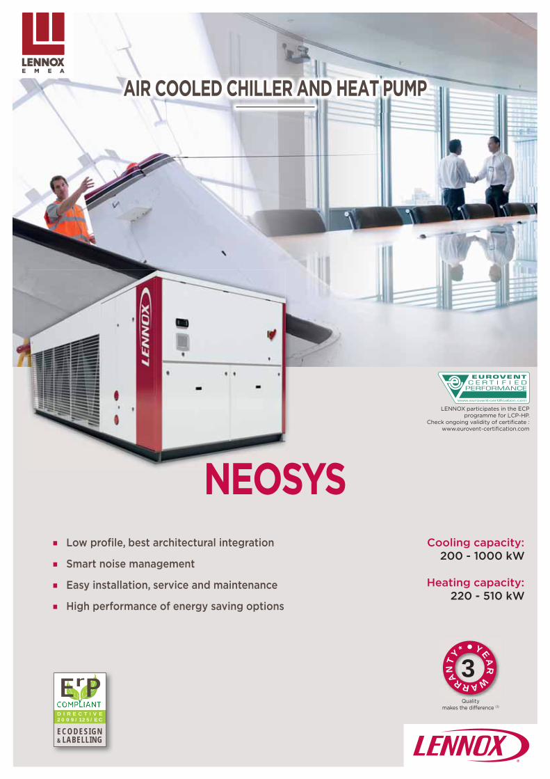
103
YEAR
WARRAN
T
Y*
3
NEOSYS
D I R E C T I V E 2 0 0 9 / 1 2 5 / E C
ECODESIGN& LABELLING
ErPQuality
makes the diff erence (1)
AIR COOLED CHILLER AND HEAT PUMP
Low profi le, best architectural integration
Smart noise management
Easy installation, service and maintenance
High performance of energy saving options
Cooling capacity:200 - 1000 kW
Heating capacity:220 - 510 kW
LENNOX participates in the ECP programme for LCP-HP.
Check ongoing validity of certifi cate :www.eurovent-certifi cation.com

104
NEOSYS200 1000 kW
| Non-contractual illustrations | GC18-E_V4 |
Main applications• Medium and large size offi ce buildings• Hotels• Hospitals• Industry
Air cooled chiller/Heat pump
LOW PROFILE, BEST ARCHITECTURAL INTEGRATION :
State of the art design for perfect architectural integration
Flat top, very low unit height (< 2m) for discrete installation
Aesthetic side anti-intrusion grilles as standard
HIGH PERFORMANCE OF ENERGY SAVING OPTIONS :
Partial and total heat recovery
eDrive, variable speed pump, electronically adjusted water fl ow rate
Fully integrated Free-Cooling
SMART NOISE MANAGEMENT :
Active Acoustic Attenuation System, adjustable sound level during day and night to satisfy local environmental constraints
EASY INSTALLATION, SERVICE AND MAINTENANCE :
Hydraulic module mounted in a sound-proofed technical cabinet
Compact hydraulic equipment with pump providing 150 or 250 kPa external static pressure
L
HS
S
EM

105
200 230 270 300 340 380 420 480
kW 208 236 273 308 351 387 430 490
2,89 2,75 2,56 2,88 2,80 2,60 2,82 2,81
4,24 4,03 3,99 4,04 4,15 3,90 4,19 4,01
3,83 3,85 3,82 3,89 3,89 3,99 4,12 4,11
% 150 151 150 153 153 157 162 161
4,88 4,93 5,01 4,95 4,98 5,01 5,02 5,04
3,20 3,26 3,50 3,30 3,40 3,50 3,50 3,60
2
4 5 6
4 5 6
kg 25,6 25,5 29,3 35,2 37,1 39,0 52,4 55,3
kPa 43 54 56 48 35 42 50 48
4" 5"
NEOSYS
| Non-contractual illustrations | GC18-E_V4 |
NAC
Cooling mode
Cooling capacity (1)
EER (1)
ESEER (2)
Seasonal Energy Effi ciency Ratio (3)
SEER
Seasonal energy effi ciency (4)
ɳs,c
Seasonal Energy Performance Ratio (5)
SEPR - High temperature (7°C)
Seasonal Energy Performance Ratio (6)
SEPR - Medium temperature (-8°C)
Electrical data
Voltage 400 V/3 Ph/50 Hz
Refrigeration circuit
Number of circuits
Number of compressors
Capacity steps
Total refrigerant load
Evaporator type Brazed plate heat exchanger
Condenser type Microchannel aluminium tube & fi ns - Air cooled
Pressure drop
Pressure drop (1)
Hydraulic connections
Type Victaulic
Diameter In/Out
Check ongoing validity of certifi cate :eurovent-certifi cation.com
Com
fort
appl
icat
ions
Proc
ess
appl
icat
ions
(1) EUROVENT certifi ed data, in accordance with standard EN 14511 : Cooling mode : Evaporator water temperature = 12/7°C Outdoor air temperature = 35°C
(2) ESEER following Eurovent calculation method, in accordance with standard EN 14511
(3) SEER in accordance with standard EN 14825.
(4) Following ecodesign regulation EU 2016/2281 on space cooling, normalized leaving water temperature at 7°C, in accordance with standard EN 14825.
(5) Following ecodesign regulation EU 2016/2281 on process cooling units, normalized leaving water temperature at 7°C, in accordance with standard EN 14825.
(6) Following ecodesign regulation EU 2015/1095 on process cooling chillers, normalized leaving water temperature at -8°C, in accordance with standard EN 14825
General data

106
NEOSYS
NAC 540 600 640 680 760 840 960 1080
kW 531 605 627 702 774 860 980 1062
2,63 2,76 2,77 2,80 2,60 2,82 2,81 2,63
4,0 4,15 4,17 4,15 3,90 4,19 4,01 4,0
4,17 4,15 4,17 4,14 4,14 4,22 4,11 4,11
% 164 163 164 163 163 166 162 162
5,02 5,01 5,01 5,05 5,03 5,01 5,04 5,01
3,60 3,70 3,70 3,60 3,50 3,50 3,60 3,60
2 4
6 10 12
6 10 12
kg 59,8 73,4 69,0 74,2 78,0 104,8 110,6 119,6
kPa 56 59 58 57 51 56 66 71
6" 8"
| Non-contractual illustrations | GC18-E_V4 |
Cooling mode
Cooling capacity (1)
EER (1)
ESEER (2)
Seasonal Energy Effi ciency Ratio (3)
SEER
Seasonal energy effi ciency (4)
ɳs,c
Seasonal Energy Performance Ratio (5)
SEPR - High temperature (7°C)
Seasonal Energy Performance Ratio (6)
SEPR - Medium temperature (-8°C)
Electrical data
Voltage 400 V/3 Ph/50 Hz 2 x 400 V/3 Ph/50 Hz
Refrigeration circuit
Number of circuit
Number of compressors
Capacity steps
Total refrigerant load
Evaporator type Brazed plate heat exchanger
Condenser type Microchannel aluminium tube & fi ns - Air cooled
Pressure drop
Pressure drop (1)
Hydraulic connections
Type Victaulic
Diameter In/Out
Check ongoing validity of certifi cate :eurovent-certifi cation.com
Com
fort
appl
icat
ions
Proc
ess
appl
icat
ions
General data
(1) EUROVENT certifi ed data, in accordance with standard EN 14511 : Cooling mode : Evaporator water temperature = 12/7°C Outdoor air temperature = 35°C
(2) ESEER following Eurovent calculation method, in accordance with standard EN 14511
(3) SEER in accordance with standard EN 14825.
(4) Following ecodesign regulation EU 2016/2281 on space cooling, normalized leaving water temperature at 7°C, in accordance with standard EN 14825.
(5) Following ecodesign regulation EU 2016/2281 on process cooling units, normalized leaving water temperature at 7°C, in accordance with standard EN 14825.
(6) Following ecodesign regulation EU 2015/1095 on process cooling chillers, normalized leaving water temperature at -8°C, in accordance with standard EN 14825

107
NAH 200 230 270 300 340 380 420 480
kW 191 217 266 295 324 361 398 442
2,60 2,34 2,54 2,52 2,46 2,71 2,50 2,41
3,99 3,76 3,98 3,94 4,01 4,08 3,86 4,14
3,93 3,91 3,92 4,00 4,23 4,20 4,12 4,16
% 154 154 154 157 166 165 162 163
5,20 5,04 5,06 5,01 5,21 5,25 5,11 5,12
3,15 3,20 3,02 3,09 3,23 3,09 3,11 3,19
kW 219 235 291 339 363 404 452 499
3,05 2,80 2,78 3,01 3,00 3,04 2,98 2,95
3,44 3,32 3,39 3,45 3,47 3,39 3,33 3.35
% 134 130 132 135 136 132 130 131
A+
2
4 5 6
kg 52,0 52,0 81,0 81,0 83,0 102,0 102,0 104,0
4 5 6
kPa 37 46 55 44 30 37 44 42
4" 5"
NEOSYS
| Non-contractual illustrations | GC18-E_V4 |
Cooling mode
Cooling capacity (1)
EER (1)
ESEER (2)
Seasonal Energy Effi ciency Ratio (3)
SEER
Seasonal energy effi ciency (4)
ɳs,c
Seasonal Energy Performance Ratio (5)
SEPR - High temperature (7°C)
Seasonal Energy Performance Ratio (6)
SEPR - Medium temperature (-8°C)
Heating mode
Heating capacity (1)
COP (1)
Seasonal Coeffi cient of Performance (7)
SCOP
Seasonal energy effi ciency (8)
ɳs,h
Seasonal energy effi ciency class (9)
Electrical data
Voltage 400 V/3 Ph/50 Hz
Refrigeration circuit
Number of circuit
Number of compressors
Total refrigerant load
Capacity steps
Evaporator type Brazed plate heat exchanger
Pressure drop
Pressure drop (1)
Hydraulic connections
Type Victaulic
Diameter In/Out
Check ongoing validity of certifi cate :eurovent-certifi cation.com
Com
fort
appl
icat
ions
Com
fort
appl
icat
ions
Proc
ess
appl
icat
ions
General data
(1) EUROVENT certifi ed data, in accordance with standard EN 14511 :
Cooling mode : Evaporator water temperature = 12/7°C Outdoor air temperature = 35°C
Heating mode : Condenser water temperature = 40/45°C Outdoor air temperature = 7°C
(2) ESEER following Eurovent calculation method, in accordance with standard EN 14511
(3) SEER in accordance with standard EN 14825.
(4) Following ecodesign regulation EU 2016/2281 on space cooling, normalized leaving water temperature at 7°C, in accordance with standard EN 14825.
(5) Following ecodesign regulation EU 2016/2281 on process cooling units, normalized leaving water temperature at 7°C, in accordance with standard EN 14825.
(6) Following ecodesign regulation EU 2015/1095 on process cooling chillers, normalized leaving water temperature at -8°C, in accordance with standard EN 14825
(7) SCOP in accordance with standard EN 14825. Heating mode performance is defi ned for average climate conditions.
(8) Following ecodesign regulation EU 813/2013 on space heaters, normalized leaving water temperature at 7°C, in accordance with standard EN 14825, average climate conditions.
(9) Following energy labelling regulation EU 811/2013 on space heaters.

108
200 230 270 300 340 380 420 480 540 600 640 680 760 840 960 1080
°C
20
3
8
46 46 46 46 46 43 46 46 43 46 46 46 43 46 46 43
NAH 200 230 270 300 340 380 420 480
°C
20
46
50
-12
200 230 270 300 340 380 420 480
dB(A)
89 89 89 91 91 91 92 92
57 57 58 59 59 59 61 61
82 83 84 85 86 86 87 87
51 52 54 54 55 55 56 56
NAC 540 600 640 680 760 840 960 1080
dB(A)
93 94 94 94 94 96 96 96
61 62 62 62 62 64 64 64
88 89 89 89 90 90 90 91
57 59 59 58 58 59 59 60
NAH 200 230 270 300 340 380 420 480
dB(A)
89 89 91 91 91 92 92 92
57 57 59 59 59 61 61 61
82 83 85 85 86 87 87 87
51 52 54 54 55 56 56 56
NEOSYS
| Non-contractual illustrations | GC18-E_V4 |
NAC
Min. outlet water temperature +5 (standard) / -10 (option)
Max. Intlet water temperature
Min. diff erence water inlet/outlet
Max. diff erence water inlet/outlet
Min. outside air temperature +6 (standard) / -20 (option)
Max. outside air temperature
Operating limits
Acoustic data
Min. outlet water temperatureCooling mode +5 (standard) / -10 (option)
Max. inlet water temperature
Min. outside air temperatureCooling mode +6 (standard) / -20 (option)
Max. outside air temperatureCooling mode
Max. outlet water temperatureHeating mode
Min. outdoor air temperatureHeating mode
(1) All data are at Eurovent conditions,
NAC
Global sound power level (1)
Sound pressure level10 meters from the unit
Minimum global sound power level with A3 system (2)
Minimum sound pressure level with A3 system (2)
10 meters from the unit
Global sound power level (1)
Sound pressure level10 meters from the unit
Minimum global sound power level with A3 system (2)
Minimum sound pressure level with A3 system (2)
10 meters from the unit
Global sound power level (1)
Sound pressure level10 meters from the unit
Minimum global sound power level with A3 system (2)
Minimum sound pressure level with A3 system (2)
10 meters from the unit(2) A3 system : Active Acoustic Attenuation system to automatically adjust the air fl ow
rate to respect night and day sound level constraints as standard

109
08
01
0204
05
07
09
10
11
12
03
03
06
01
02
03
04
05
06
07
08
09
10
11
12
NAC 200 230 270 300 340 380 420 480A
mm
3590 3590 3590 4620 4620 4620 5650 5650
B 2280 2280 2280 2280 2280 2280 2280 2280
C 2025 2025 2025 2025 2025 2025 2025 2025
kg1961 1989 2253 2643 2955 2997 3532 3604
1983 2011 2278 2676 3003 3045 3580 3661
NAC 540 600 640 680 760 840 960 1080A
mm
5650 6680 6680 9040 9040 11100 11100 11100
B 2280 2280 2280 2280 2280 2280 2280 2280
C 2025 2025 2025 1964 1964 1964 1964 1964
kg3655 4086 4105 6495 6564 7681 7806 7884
3712 4152 4175 6770 6854 7981 8141 8229
NAH 200 230 270 300 340 380 420 480A
mm
3590 3590 4620 4620 4620 5650 5650 5650
B 2280 2280 2280 2280 2280 2280 2280 2280
C 2025 2025 2025 2025 2025 2025 2025 2025
kg2154 2153 2881 3347 3301 3972 4020 4091
2176 2175 2906 3380 3349 4020 4066 4148
C
A
B
C
A
B
NEOSYS
| Non-contractual illustrations | GC18-E_V4 |
Integrated hydraulic moduleWater fi lter (supplied loose)
Air purge
Pressure tap
Pump
Safety valve with manometer
Expansion vessel
Electronic fl ow switch
Plate heat exchanger
Setting valve
Pressure tap and drain valve
Return temperature sensor
Supply temperature sensor
Dimensions and weights
Shipping weight
Operating weight
Shipping weight
Operating weight
Shipping weight
Operating weight
Sizes 200 to 640
Sizes 680 to 1080
IN
OUT

110

111
HYDROLEAN
D I R E C T I V E 2 0 0 9 / 1 2 5 / E C
ECODESIGN& LABELLING
ErP
WATER COOLED CHILLER AND HEAT PUMPCONDENSERLESS LIQUID CHILLER
Reduced energy bills, high seasonal effi ciency
Very compact
Easy installation and maintenance
Available in 3 versions
Cooling capacity:20 - 160 kW
LENNOX participates in the ECP programme for LCP-HP.
Check ongoing validity of certifi cate :www.eurovent-certifi cation.com
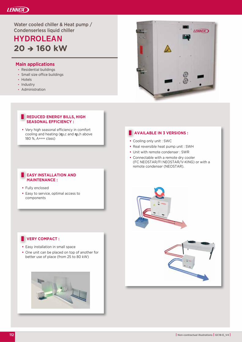
112
HYDROLEAN20 160 kW
| Non-contractual illustrations | GC18-E_V4 |
REDUCED ENERGY BILLS, HIGH SEASONAL EFFICIENCY :
Very high seasonal effi ciency in comfort cooling and heating (ɳs,c and ɳs,h above 180 %, A+++ class)
RS
Main applications• Residential buildings• Small size offi ce buildings• Hotels• Industry• Administration
Water cooled chiller & Heat pump /Condenserless liquid chiller
VERY COMPACT :
Easy installation in small space One unit can be placed on top of another for
better use of place (from 25 to 80 kW)
EASY INSTALLATION AND MAINTENANCE :
Fully enclosed Easy to service, optimal access to
components
AVAILABLE IN 3 VERSIONS :
Cooling only unit : SWC Real reversible heat pump unit : SWH Unit with remote condenser : SWR Connectable with a remote dry cooler
(FC NEOSTAR/FI NEOSTAR/V-KING) or with a remote condenser (NEOSTAR).
V
EM
A

113
HYDROLEAN - SWC
HYDROLEAN SWC 025 035 050 070 080 100 120 135 160
kW 25,8 37,9 50,8 71,9 83,6 95,7 117,5 132,7 156,4
4,37 4,26 4,27 3,89 3,77 4,25 4,04 4,19 3,96
4,78 4,59 5,40 5,13 4,80 5,68 5,55 5,33 5,25
%
1 2
1 2 3
1 2 3
kg 3,5 4,5 6,6 7,0 7,2 12,0 12,1 15,1 15,5
1" 1/2 DN40
m3/h 5,3 7,8 10,4 15,0 17,0 19,5 24,1 26,9 32,8
l 3,0 4,0 5,2 5,7 5,7 10,0 10,0 12,8 12,8
kPa21,6 26,9 33,6 56,9 71,4 30,3 48,1 42,7 58,6
600
m3/h 4,4 6,5 8,6 12,6 14,4 16,5 20,6 22,7 28,0
l 3,0 4,0 5,2 5,7 5,7 10,0 10,0 12,8 12,8
kPa16,5 20,5 25,4 41,4 52,9 24,7 34,5 31,6 41,7
600
| Non-contractual illustrations | GC18-E_V4 |
General data
Cooling modeCooling capacity (1)
EER (1)
ESEER (2)
Seasonal Energy Effi ciency Ratio (3)
SEER 5,33 5,26 5,72 5,12 5,03 5,43 5,19 5,30 5,10
Seasonal energy effi ciency (4)
ɳs,c208 206 224 200 196 212 203 207 199
Seasonal Energy Performance Ratio (5)
SEPR - Medium temperature (-8°C) 4,15 4,16 3,96 3,93 3,84 4,18 4,10 4,11 4,05
Electrical dataVoltage 400 V/3 Ph/50 Hz
Refrigeration circuitNumber of circuits
Number of compressors
Number of capacity steps
Total refrigerant load
Hydraulic connectionsHydraulic connections type Threaded male
Water inlet/outlet
CondenserCondenser type Brazed plate heat exchanger
Water fl ow rate
Water volume
Pressure drop
Water operating pressure
EvaporatorEvaporator type Brazed plate heat exchanger
Water fl ow rate
Water volume
Pressure drop
Water operating pressure
Check ongoing validity of certifi cate :eurovent-certifi cation.com
Com
fort
appl
icat
ions
Proc
ess
appl
icat
ions
(1) EUROVENT certifi ed data, in accordance with standard EN 14511 : Cooling mode : Evaporator water temperature = 12/7°C Condenser water temperature = 30/35°C
(2) ESEER following Eurovent calculation method, in accordance with standard EN 14511
(3) SEER in accordance with standard EN 14825.
(4) Following ecodesign regulation EU 2016/2281 on space cooling, normalized leaving water temperature at 7°C, in accordance with standard EN 14825.
(5) Following ecodesign regulation EU 2015/1095 on process cooling chillers, normalized leaving water temperature at -8°C, in accordance with standard EN 14825

114
HYDROLEAN - SWH
HYDROLEAN - SWH 025 035 050 070 080 100 120 135 160
kW 25,5 37,6 50,3 71,6 81,8 95,0 116,5 131,9 155,8
4,01 3,89 3,92 3,56 3,68 3,93 3,72 3,88 3,70
4,57 4,48 5,48 4,60 4,62 5,26 5,33 5,14 5,11
5,32 5,23 5,76 5,13 5,03 5,55 5,22 5,25 5,12
% 208 204 225 200 196 217 204 205 200
4,16 4,14 4,00 3,93 3,82 4,19 4,09 4,11 4,03
kW 28,0 41,4 55,5 79,6 91,7 104,6 129,3 145,1 173,0
3,73 3,73 3,68 3,51 3,62 3,70 3,61 3,70 3,60
4,98 4,95 5,15 4,93 4,73 5,23 5,05 5,13 4,78
% 194 193 201 192 184 204 197 200 186
A+++
1 1 2
1 2 3
1 2 3
kg 3,5 4,5 6,9 7,4 7,6 12,3 12,3 15,5 16,0
1" 1/2 / DN40 2" DN50
m3/h 5,3 7,8 10,4 15,0 17,0 19,5 24,1 26,9 32,9
l 3,0 4,0 5,2 5,7 5,7 10,0 10,0 12,8 12,8
kPa17,6 25,0 31,3 59,0 73,6 30,3 45,3 39,8 58,6
600
m3/h 4,4 6,5 8,6 12,6 14,4
l 3,0 4,0 5,2 5,7 5,7
kPa16,5 20,5 25,4 41,4 52,9 22,6 31,3 29,0 40,9
600
| Non-contractual illustrations | GC18-E_V4 |
General data Check ongoing validity of certifi cate :eurovent-certifi cation.com
Cooling modeCooling capacity (1)
EER (1)
ESEER (2)
Seasonal Energy Effi ciency Ratio (3)
SEER
Seasonal energy effi ciency (4)
ɳs,c
Seasonal Energy Performance Ratio (5)
SEPR - Medium temperature (-8°C)
Heating modeHeating capacity (1)
COP (1)
Seasonal Coeffi cient of Performance (6)
SCOP
Seasonal energy effi ciency (7)
ɳs,h
Seasonal energy effi ciency class (8)
Electrical dataVoltage 400 V/3 Ph/50 Hz
Refrigeration circuitNumber of circuits
Number of compressors
Number of capacity steps
Total refrigerant load
Hydraulic connectionsHydraulic connections type Victaulic
Water inlet/outlet
CondenserCondenser type Brazed plate heat exchanger
Water fl ow rate
Water volume
Pressure drop SWC/SWH
Water operating pressure
Evaporator
Evaporator type Brazed plate heat exchanger
Water fl ow rate 16,5 20,6 22,7 28,0
Water volume 10,0 10,0 12,8 12,8
Pressure drop SWC/SWH
Water operating pressure
Com
fort
appl
icat
ions
Com
fort
appl
icat
ions
Proc
ess
appl
icat
ions
(1) EUROVENT certified data, in accordance withstandard EN 14511 :Cooling mode Evaporator water temperature = 12/7°C Condenser water temperature = 30/35°C
Heating mode : Condenser water temperature = 40/45°CTemperatura da água no evaporador = 10 °C
Evaporator water outlet temperature calculated with the same water fl ow as in cooling mode
(2) ESEER following Eurovent calculation method, inaccordance with standard EN 14511
(3) SEER in accordance with standard EN 14825.
(4) Following ecodesign regulation EU 2016/2281 on space cooling, normalized leaving water temperature at 7°C, in accordance with standard EN 14825.
(5) Following ecodesign regulation EU 2015/1095 on process cooling chillers, normalized leaving water temperature at -8°C, in accordance with standard EN 14825
(6) SCOP in accordance with standard EN 14825. Heating mode performance is defi ned for average climate conditions.
(7) Following ecodesign regulation EU 813/2013 on space heaters, normalized leaving water temperature at 35°C, in accordance with standard EN 14825, average climate conditions.
(8) Following energy labelling regulation EU 811/2013 on space heaters.

115
HYDROLEAN - SWR
SWR 025 035 050 070 080
kW 23,9 35,3 47,3 68,2 80,1
3,51 3,50 3,45 3,33 3,24
1
1 2
1 2
kg
5/8'' 7/8''
7/8'' 1''1/8 1''3/8
m3/h 4,1 6,1 8,2 11,8 13,8
l 3,0 4,0 5,2 5,7 5,7
kPa12,0 16,0 20,0 37,0 48,3
600
SWR 100 120 135 160
kW 89,4 110,9 124,2 148,2
3,52 3,43 3,46 3,39
2
3
3
kg
7/8'' - 5/8" 7/8''
1''1/8 - 7/8" 1'' 1/8 1'' 3/8 - 1" 1/8
m3/h 15,4 19,1 21,4 25,6
l 10,0 10,0 12,8 12,8
kPa20,0 29,3 25,8 36,3
600
| Non-contractual illustrations | GC18-E_V4 |
General data
Cooling mode
Cooling capacity (1)
EER (1)
Electrical data
Voltage 400 V/3 Ph/50 Hz
Refrigeration circuit
Number of circuit
Number of compressors
Capacity steps
Charge per circuit Nitrogen charge
Hydraulic connections
Hydraulic connections type Threaded male
Discharge line
Liquid line
Evaporator
Evaporator type Brazed plate heat exchanger
Water fl ow rate
Water volume
Pressure drop
Water operating pressure
Cooling mode
Cooling capacity (1)
EER (1)
Electrical data
Voltage 400 V/3 Ph/50 Hz
Refrigeration circuit
Number of circuit
Number of compressors
Capacity steps
Charge per circuit Nitrogen charge
Hydraulic connections
Hydraulic connections type Victaulic
Discharge line
Liquid line
Evaporator
Evaporator type Brazed plate heat exchanger
Water fl ow rate
Water volume
Pressure drop
Water operating pressure(1) Conditions data :
Cooling mode : Evaporator water temperature = 12/7°C - Condensing temperature = 45 °C

HYDROLEAN - SWC/SWH/SWR
A B
C
A B
C
SWC - SWH 025 > 160
SWR 025 > 160
°C
25
20
20 -
- 35
25 -
- 62
55 -
HYDROLEAN 025 035 050 070 080 100 120 135 160
A
mm
502 645
B 802 1470
C 815 854 1705
SWC
kg176 249 333 378 309 606 617 739 760
166 236 316 360 290 574 585 698 719
SWH
kg178 251 338 385 404 614 625 747 771
168 238 321 366 385 582 593 706 729
SWR
kg155 196 293 314 321 499 510 600 621
148 187 281 301 308 477 488 572 593
HYDROLEAN - SWC/SWH/SWR 025 035 050 070 080 100 120 135 160
dB(A)69 71 72 74 75 75 76 79 81
61 62 64 65 65 66 66 71 73
116 | Non-contractual illustrations | GC18-E_V4 |
Operating limits
Mini. evaporator outlet water temperature +5 (standard)-10 (option)
Maxi. evaporator inlet water temperature
Maxi. evaporator outlet water temperature
Mini. condenser inlet water temperature (1)
Mini. condensing temperature
Mini. condenser outlet water temperature
Maxi. condensing temperature
Maxi. condenser outlet water temperature
Dimensions and weights
Operating weight
Weight without water
Operating weight
Weight without water
Operating weight
Weight without water
Sizes 025 to 100 Sizes 120 to 160
(1) Below this value, water pressostatic valve is mandatory (option).
Acoustic data
Global sound power level (1)
Global sound power level with acoustic jacket option (1)

117
D I R E C T I V E 2 0 0 9 / 1 2 5 / E C
ECODESIGN& LABELLING
ErP
MWC/MRC
WATER COOLED CHILLER AND HEAT PUMPCONDENSERLESS LIQUID CHILLER
Reduced energy bills, "best in class" seasonal effi ciency
Easy installation and maintenance
Available in 3 versions
Cooling capacity:MWC 180 - 400 kWMRC 180 - 720 kW
LENNOX participates in the ECP programme for LCP-HP.
Check ongoing validity of certifi cate :www.eurovent-certifi cation.com

118
MWC 180 400 kWMRC 180 720 kW
| Non-contractual illustrations | GC18-E_V4 |
MW
C w
ith o
ptio
nal c
asin
g
Main applications• Medium and large size offi ce buildings• Hotels• Hospitals• Industry
Water cooled chiller & Heat pump /Condenserless liquid chiller
REDUCED ENERGY BILLS, HIGH SEASONAL EFFICIENCY :
Very high seasonal effi ciency in comfortcooling, exceeding 2021 ErP target(ɳs,c above 200 %)
Very high seasonal effi ciency in comfortheating (ɳs,h above 200 %, A+++ class)
RS
EASY INSTALLATION AND MAINTENANCE :
Very compact dimension and limited footprintMWC : Width 820 mm / Length 2150 mm
Easy to service, optimal access to components
AVAILABLE IN 3 VERSIONS :
Cooling only unit : MWC
Heat pump unit : MWC with hot water setpointcontrol option and supply hot water up to 56°C
Unit with remote condenser : MRC Connectable with a remote dry cooler
(FC NEOSTAR/FI NEOSTAR/V-KING) or with aremote condenser (NEOSTAR or MXW).
E
A
2021READY
COMFORT COOLING
n°2016/2281

119
MWC 180 230 280 330 380
kW 182 228 275 327 372
4,64 4,56 4,60 4,60 4,60
6,74 6,31 6,21 6,25 6,03
5,13 5,45 5,40 5,45 5,58
% 200 213 211 213 218
4,16 4,21 4,18 4,19 4,15
kW 196 246 297 351 401
4,05 4,00 4,06 4,05 4,05
5,43 5,63 5,50 5,53 5,58
% 212 220 215 216 218
A+++
2
4
4 5 6 5 4
kg 16 24 28 28 44
4"
m3/h 33,8 42,4 51,1 60,5 69,1
l 13 24 35 35 43
kPa38,6 32,1 25,4 34,8 33,7
600
m3/h 31,3 39,2 47,3 56,2 63,9
l 13 24 24 35 35
kPa34,9 28,9 40,7 31,5 40,2
600
MWC
| Non-contractual illustrations | GC18-E_V4 |
General data
Cooling modeCooling capacity (1)
EER (1)
ESEER (2)
Seasonal Energy Effi ciency Ratio (3)
SEER
Seasonal energy effi ciency (4)
ɳs,c
Seasonal Energy Performance Ratio (5)
SEPR - Medium temperature (-8°C)
Heating modeHeating capacity (1)
COP (1)
Seasonal Coeffi cient of Performance (6)
SCOP
Seasonal energy effi ciency (7)
ɳs,h
Seasonal energy effi ciency class (8)
Electrical dataVoltage 400 V/3 Ph/50 Hz
Refrigeration circuitNumber of circuit
Number of compressor
Capacity steps
Total refrigerant load
Hydraulic connections Victaulic
Water inlet/outlet
Condenser Brazed plate heat exchangerWater fl ow rate
Water volume
Pressure drop
Water operating pressure
Evaporator Brazed plate heat exchangerWater fl ow rate (1)
Water volume
Pressure drop (1)
Water operating pressure
Com
fort
appl
icat
ions
Com
fort
appl
icat
ions
Proc
ess
appl
icat
ions
Check ongoing validity of certifi cate :eurovent-certifi cation.com
(1) EUROVENT certified data, in accordance withstandard EN 14511 :Cooling mode Evaporator water temperature = 12/7°C Condenser water temperature = 30/35°C
Heating mode : Condenser water temperature = 40/45°CTemperatura da água no evaporador = 10 °CEvaporator water outlet temperature calculated with the same water fl ow as in cooling mode
(2) ESEER following Eurovent calculation method, inaccordance with standard EN 14511
(3) SEER in accordance with standard EN 14825.
(4) Following ecodesign regulation EU 2016/2281 on space cooling, normalized leaving water temperature at 7°C, in accordance with standard EN 14825.
(5) Following ecodesign regulation EU 2015/1095 on process cooling chillers, normalized leaving water temperature at -8°C, in accordance with standard EN 14825
(6) SCOP in accordance with standard EN 14825. Heating mode performance is defi ned for average climate conditions.
(7) Following ecodesign regulation EU 813/2013 on space heaters, normalized leaving water temperature at 35°C, in accordance with standard EN 14825, average climate conditions.
(8) Following energy labelling regulation EU 811/2013 on space heaters.

120
MRC 180 230 280 330 380
kW 161 202 242 289 329
3,24 3,21 3,18 3,23 3,20
2
4
4 5 6 5 4
1" 1/8 1" 3/8 - 1"1/8 2 x 1" 3/8
7/8" 1" 1/8 - 7/8" 2 x 1" 1/8
m3/h 26,8 22,3 31,0 24,1 30,6
l 13 24 24 35 35
kPa148,3 186,3 223,3 266,4 303,3
600
MRC 450 510 570 650 720
kW 382 433 494 555 615
3,18 3,16 3,21 3,15 3,10
2
6
6
2 x 1" 5/8 2" 1/8- 1" 5/8 2 x 2" 1/8
2 x 1" 3/8 1" 5/8 - 1" 3/8 2 x 1" 5/8
m3/h 30,7 31,3 35,0 43,6 53,2
l 43 43 61 61 61
kPa352,6 399,9 456,5 512,2 568,0
MRC
| Non-contractual illustrations | GC18-E_V4 |
Cooling mode
Cooling capacity (1)
EER (1)
Electrical data
Voltage 400 V/3 Ph/50 Hz
Refrigeration circuit
Number of circuit
Number of compressor
Capacity steps
Hydraulic connections Victaulic
Discharge line
Liquid line
Evaporator Brazed plate heat exchanger
Water fl ow rate
Water volume
Pressure drop
Water operating pressure
General data
(1) Conditions data : Cooling mode : Evaporator water temperature = 12/7°C - Condensing temperature = 45 °C

121
MWC/MRC
MWC MWC180 > 380
MRC180 > 720
°C
-10
20
3
8
20 -
- 25
56 -
- 62
MWC/MRC MRC180 230 280 330 380 450 510 570 650 720
A
mm
820 1200
B 2150 2200
C 1645 1870 1870
MWCm² 1,8 2,6
kg756 974 1158 1328 1534 1984 2100 2240 2440 2480
736 914 1088 1248 1444 1894 1990 2110 2270 2310
MRCm² 1,8 2,6
kg650 810 950 1120 1290 1660 1740 1870 1980 2020
620 770 910 1080 1240 1620 1690 1790 1890 1930
MWC / MRC MRC
180 230 280 330 380 450 510 570 650 720
dB(A)82 87 89 91 92 93 93 94 96 98
71 78 81 83 84 85 85 86 87 88
A B
C
A B
C
MWC
MRC
| Non-contractual illustrations | GC18-E_V4 |
Operating limits
Acoustic data
Mini. evaporator outlet water temperature
Maxi. evaporator outlet water temperature
Mini. diff erence water inlet/outlet
Maxi. diff erence water inlet/outlet
Mini. condenser outlet water temperature
Minimum discharge temperature
Maximum condenser outlet water temperature :Full capacity operation
Maximum discharge temperature :Full capacity operation
Evaporator and condenser water Delta T = 5°C
Dimensions and weights
Footprint
Operating weight
Weight without water
Footprint
Operating weight
Weight without water
Global sound power level (1)
Global sound power level with panel enclosure option (1)

122
eCO
MFO
RT
ECO
LEA
NEA
C/E
AR
NEO
SYS
NA
C/N
AH
AQ
UA
4
AA
H
| Non-contractual illustrations | GC18-E_V4 |
AIR COOLED CHILLERS AND HEAT PUMPSSTANDARD EQUIPMENTS AND OPTIONS
Refrigerant circuit
R410A
Winter cooling operation
Low leaving water temperature down to -10°C
Compressor
Multiscroll
Low noise
Super low noise
Expansion valveThermostatic
Electronic
Fans
Axial fan
Variable air fl ow control of condensation : HP fl oating
EC fan
Fan static pressure
Air coil
Standard copper tube/aluminum fi n (1)
Micro channel heat exchanger (2)
Heavy anti-corrosion coil treatment
Coils protection guards
Heat exchanger Braze plate heat exchanger
Electrical
Main disconnect switch
Phase reversal protection
Antifreeze protection
Softstarter
Water tank modulating auxiliary electrical heater (heat pump)
Power factor correction
Energy meter
Hydraulic module
Paddle fl ow switch
Electronic fl ow switch
Water fi lter
Flange connection
Water tank
Low-pressure single pump
Low-pressure twin pump
High-pressure single pump
High-pressure twin pump
eDrive high-pressure single pump (variable primary fl ow)
eDrive high-pressure twin pump (variable primary fl ow)
By-pass valve for Delta P control (eDrive)
Control and communication
Modbus RS485 communication interface
Lonworks® FTT10 communication interfaceBACnet MSTP communication interface
Modbus/BACnet/Ethernet TCP/IP communication interface
Basic display
Advanced display
Service display
Remote comfort display
Extension board for aditional input /output
Energy saving
Partial heat recovery
Total heat recovery
Free-cooling
MiscellaneousRubber anti-vibration mounts
Spring anti-vibration mounts
PackingTruck packaging for long distance
Container packing(1) : NAH only / (2) : NAC only
Standard equipment
Option

123| Non-contractual illustrations | GC18-E_V4 |
Standard equipment
Option
WATER COOLED CHILLERS AND HEAT PUMPSSTANDARD EQUIPMENTS AND OPTIONS
HYDROLEANSWC/SWH/SWR
MWCMWC/MWR
Refrigerant circuit
R410A
Brine operation down to -10°c
HP/LP pressure gauges
CompressorMultiscroll
Low noise
Expansion valvesThermostatic
Electronic
Electrical
Main disconnect switch
Control & power equipment single evaporator pump
Control & power equipment dual evaporator pump
Control & power equipment single condenser pump
Control & power equipment dual condenser pump
Control & power equipment of outside fans (1 to 4)
Hydraulic options
Paddle fl ow switch
Electronic fl ow switch
Evaporator water fi lter
Condenser water fi lter
Evaporator fl ange connections
Condenser fl ange connections
Pressure regulated water valve
Control and communication
Modbus RS485 communication interface
Lonworks® FTT10 communication interface
BACnet MSTP communication interface
Hot water set-point control (heat pump mode)
Remote comfort display
Service display
Extension board for aditional input /output
Miscellaneous Rubber anti-vibration mounts

124
20 - 1200 kW
FC / FI NEOSTARFC NEOSTAR "City"
Compactness and high effi ciency
FI NEOSTAR "Industry"
Low pressure drop and high capacity
Wide range up to 1,200 kW, optimized pressure drops
FLAT BED DRY COOLER
Range non subject to the ErP directive
LENNOX participates in the ECP programme for HE.
Check ongoing validity of certifi cate :www.eurovent-certifi cation.com

FC/FI NEOSTAR20 1200 kW
125| Non-contractual illustrations | GC18-E_V3 |
DESCRIPTION :Usefully replaces cooling towers :
No air and water bacteria contamination No water consumption No steam production Flexible use in winter Easy control of fl uid temperature in winter Optimised solution (noise level, energy consumption,
size, type of temperature control…) thanks to many selection choices Sustainable performance thanks to the type of
louvers
VENTILATION :
Motor fans : Ø 800 or 910
Motor fan wired as standard and factory connected as follows :. 1 to 3 electrical boxes for the models L (motors connected in series),
. 2 to 8 electrical boxes for the models P (motors connected in parallel).
Possibility to deliver the units unwired (on request, option SCU or SCM).
Fan guards compliant with safety standards.
Special voltage ratings (FC/FI NEOSTAR): . M60 : Fan motor 400V/3/60Hz, IP54, class F,
in version 06P Ø 910 mm . M26 : Fan motor 230V/3/60Hz, IP54, class F,
in version 06P Ø 910 mm
More details on following page.
COIL :
Dry coolers equipped with coils with the following characteristics :. Special fi ns to reduce clogging and to enable effi cient maintenance to ensure a sustainable performance
. Copper tubes in a staggered arrangement and corrugated aluminium fi ns for optimum heat transfer
. Headers with air vents and drain plugs
. Connections : steel pipe, fl anges
Options :. Vinyl protection (BAE) or Blygold Polual XT protection (BXT) off ering greater corrosion resistance when used in aggressive atmospheres
. Superposed circuits HT / LT
PERFORMANCES :
As the performance of a dry cooler varies a lot with each working condition, it is not possible to present a selection method in this document.Only the selection software, at your disposal on www.lennoxemea.com, will allow you to select the dry cooler which suits the best your needs.
CASING:
Galvanized and white pre-painted sheet steel Long-lasting corrosion resistance (standard ISO 7253)
and aesthetic quality Facilitated maintenance thanks to a trapdoor between
two fans for a direct access to the battery (as standard, except on A modules) Salt mist corrosion and Kesternich tests on all
components Units delivered screwed to a wooden base Full crate packaging as option
Main applications• Air conditioning, free cooling, co-generation, power plants, process,
industry ... and cooling all kinds of fl uids compatible with copper, with a maximum inlet temperature of 100°C.
Dry cooler
DU
C
C
P
V

FI H PU 06 D L 04 D5(1) (2) (3) (4) (5) (6) (7) (8)
RAL
REH
RE2
RE3
RE4
ECB
MTH
IRP
C2V
SCU
M60
M26
(1) :
VEX
VID
BAE
BXT
FC/FI NEOSTARPOWER SILENCE
PN PU PM FCH PU PU EC SN SN SE SUSE EC SU EC
<70°C <60°C <60°C <°80C 60°C <80°C <80°C <80°C <80°C <60°C <60°C
Ø 800 910 910 910 910 800 910 800 800 800 800
06P 06P 04P 06P - 08P 08P 12P 12P 16P - -
400V / 3 / 50 Hz
F F F H F F H F F F F
880 885 1230 890 1195 680 650 440 - 1020 730
83 84 95 85 91 73 75 68 - 88 78
670 685 900 730 - 540 480 - 330 255 - -
75 78 88 80 - 69 68 - 61 48 - -
126
FC/FI NEOSTAR
| Non-contractual illustrations | GC18-E_V4 |
Nomenclature
Options
Ventilation
Control optionsSee page 129
Casing :Special colour
Legs extended by 240 mm (ground clearance = 800 mm)
Legs extended by 840 mm (ground clearance = 1400 mm)
Legs extended by 1340 mm (ground clearance = 1900 mm)
Legs extended by 1840 mm (ground clearance = 2400 mm)
Full crate packaging
Ventilation:
Motors equipped with a protection thermostat. Recommended if frequent starting sequences (more than 30 startings per hour) or when used with a speed controller
Proximity rotary switch
2-speed factory wired in the switching box
Unwired fans (to be specifi ed while ordering)
Motor fan 400 V/3/60Hz (1)
Motor fan 230 V/3/60Hz (1)
Please consult us for details
Coil :
Expansion vessel
Special circuits, totally drainable
Vinyl protection of the fi ns
Blygold Polual XT protection of fi ns
Air temperature
Number of poles
Class
DEL
TA
(D) rpm
dB(A)
STA
R
(Y) rpm
dB(A)
EC motor
(1) FC = Dry cooler “City” FI = Dry cooler “Industry”(2) H = H Class motor (PU and SN versions only)(3) Type of fans PN - PU - PM - FCH PU - PU EC SN - SE - SU - SE EC - SU EC(4) Number of poles
(5) D = delta coupling - Y = star coupling(6) Fan arrangement : L : fans in line - P : fans in parallel(7) Number of fans(8) Type of module
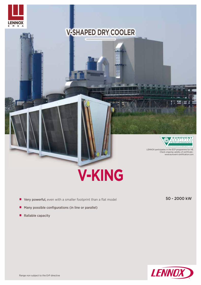
127
50 - 2000 kW
V-KING
V-SHAPED DRY COOLER
Very powerful, even with a smaller footprint than a fl at model
Many possible confi gurations (in line or parallel)
Raliable capacity
Range non subject to the ErP directive
LENNOX participates in the ECP programme for HE.Check ongoing validity of certifi cate :
www.eurovent-certifi cation.com

128
V-KINGPOWER SILENCE
PN PU PM PU PU EC SN SN SU SESE EC SU EC
<70°C / 80°C <60°C <40°C /
60°C <°80C 60°C <80°C <80°C <80°C <80°C <60°C <60°C
Ø 800 910 910 910 910 800 910 800 800 800 800
06P 06P 04P 06P EC 08P 08P 12 -16P 12P - -
400V / 3 / 50 Hz
F F F H F F H F F F F
880 885 1230 890 250-1195 680 650 - 430 250-1020 250-735
82 89 95 85 91 73 75 - 68 88 78
670 685 900 730 - 540 480 255 - 330 - - -
75 81 87 80 - 69 68 48 - 61 - - -
| Non-contractual illustrations | GC18-E_V4 |
V-KING50 2000 kW*
DESCRIPTION :
Large range :. From L2 (in line, 2 fans) to L10. From P4(parallel, 4 fans) to P20
VENTILATION :
Standard : 400V/3/50Hz (class F) with external rotor, two-speed (delta-star connection) H class : 400V/3/50Hz,
two-speed (delta-star connection) EC : motor fan units with electronic switching
to reduce energy consumption Wiring path inside the product
COIL :
Staggered copper tubes and embossed aluminum fi ns for optimal heat exchange. Fin spacing of 1,9 mm to 3 mm, depending on application
and fouling constraints. Stacked HT/LT circuits possible
CASING:
Self-supporting, highly rigid metal frame, with horizontal feet every 2 fans Magnesium-zinc material 20 mm or 30/10 mm thick Epoxy painted structure for maximum corrosion
resistance
Main applications• Air conditioning, free cooling, cogeneration, power plants, process,
industry, with a maximum inlet temperature of 80°C.
* Air inlet temperature : 25°C / Fluid : water / Maximum pressure drop : 10 m of water column / Fluid inlet temperature : 40°C / Fluid outlet temperature : 35°C
V-shaped dry cooler
D
C
C
V
Ventilation
In line confi guration
Parallel confi guration
Air temperature
Number of poles
Class
DEL
TA (
D) rpm
dB(A)
STA
R
(Y) rpm
dB(A)
EC motor

129
RAL
PAV
M60
MTH
IRP
IRP G
C2V
SCU
EC
RDB RNR
VEX
MCI
BCB
BAE
BXT Blygold Polual XT protection of fi ns
V-KING
| Non-contractual illustrations | GC18-E_V4 |
Options
Control optionsFC/FI NEOSTAR and V-KING ranges
AC MOTOR EC MOTOR
Casing :Special colour
Anti-vibration pads
Ventilation:Motor fan 400 V/3/60Hz
Motors equipped with a thermal protection
Motor proximity rotary switch
General proximity rotary switch
2-speed factory wired in the switching box
Unwired fans (to be specifi ed while ordering)
EC motor
Noise reduction (Diff usor/AxiTop)
Coil :
Expansion vessel
Multi-circuits HT/LT
Flange against fl ange
Protection of the fi n
Wiring and power
SCU Without factory wiring
APC * Power wired on connections (no protection integrated)
Wiring and protection
CMPIP 54 Motor protection cabinet, With one contactor /fan, one general fault report, one main switch
Control / Simple control (cascade ON/OFF)
RT1
CMP included
A thermostatic cascade control in a IP54 electrical box, allowing management of several capacity steps :
1 to 4 capacity steps :. Management of 2 circuits
4 to 10 capacity steps :. Possible to program a day/night operation. Integrated clock. Management of fl oating HP
Advanced control (variation)
RT2 CMP included / Voltage variationControl IP54 box
RT3 CMP included / frequency variation Control IP 54 boxe
Wiring and power
SCM Without factory wiring
CSB * Power wired on connections
CCE Power wired in box and protection for each stage included (for L each fan, for P every 2 fans)
Simple control (cascade ON/OFF)
SE1* Direct signal toward fan and signal duplicated from one fan to another
SE3 Direct signal to master fan and duplication of signal for slaves fans
Advanced control
CE1..3 Electronic regulator
Additional functions
WMA Max speed pre set
MJN Max speed for night
ADR Fan bus
* : If no other choice selected while ordering, the unit with EC motor will be delivered with CSB connection and SE1 control.

18 - 1240 kW
NEOSTARNEOSTAR POWER Performance and low space requirement
Capacity up to 1,250 kW
Compactness: optimized heat exchange for reduced size
NEOSTAR SILENCE Effi ciency and low noise
Low rotation speed motors with optimized electrical power con-sumption
Perfect integration in an urban environment, extremely quiet motors
Electronic switching motor (EC) as option
CONDENSER
Range non subject to the ErP directive

NEOSTAR18 1240 kW
PN (1) 06 (2) D (3) P (4) 08 (5) A2 (6)
131| Non-contractual illustrations | GC18-E_V4 |
Main applications• The NEOSTAR air cooled condensers are designed for
refrigeration or air conditioning applications and outdoor installation. The 470 basic models cover a capacity range from 18 to 1250 kW.
Axial fan condenser
DESCRIPTION :
COMPATIBLE WITH MANY REFRIGERANTS
To perfectly fi t any application, NEOSTAR range is available in :
NEOSTAR POWER range : more power in a space-saving unit. As an option, an electronic switching motor (EC) is proposed on all models to help reduce the energy footprint of the user's installations.
NEOSTAR SILENCE range : perfectly adapted to town centre commercial applications and any other applications where quiet operation is a key factor. In compliance with EUROVENT standards, the sound pressure level measured 10 metres from the unit is 19 dB(A) per module
VENTILATION :
NEOSTAR range equipped as standard with 2-speed, external rotor fans (star or delta connections).
NEOSTAR POWER equipped with the following motor fan units:. Ø 800 mm (PN) : 06P (D/Y) = 885/685 rpm. Ø 910 mm (PU) : 06P (D/Y) = 880/670 rpm
NEOSTAR SILENCE equipped with the following motor fan units:. Ø 800 mm : 08P (D/Y) = 680/540 rpm, . Ø 800 mm : 12P (D/Y) = 440/330 rpm (special fan). Ø 800 mm : 16P (Y) = 255 rpm.
Enclosed motors : 400V/3/50Hz, IP54, class F, compliant with standard EN 60529, permanently lubricated. Please contact us when the temperature exceeds 60°C :
Possibility to deliver the units unwired (on request, option SCU).
Fan guards compliant with safety standards EC motor : Electronic switching fan motors (EC) proposed as an
option ensuring optimised operation of your installation. This motor allows energy savings for a given power rating: a
detailed comparison of the energy balance may be carried out for each project.
COIL :
NEOSTAR range equipped with high-performance, fi nned coil designed with profi led aluminium fi ns crimped onto internally grooved copper tubes
New optimised fi n specially designed to improve performance, effi ciency and compactness of the units
Special coil coatings available (Vinyl protection (BAE), Blygold Polual XT protection (BXT)), off ering greater corrosion resistance when used in aggressive atmospheres
OPTIONS :
Same as FC/FI NEOSTAR range (see previous page)
CASING:
Galvanized and white pre-painted sheet steel. Salt mist corrosion and Kesternich tests on all components Units delivered screwed to a wooden base.
D C
C
O
V
Nomenclature
(1) Type of fansPN - PU - SN - SE - SU16Y - SN - SE EC - SU EC
(2) Number of poles(3) D = delta coupling - Y = star coupling(4) Fan arrangement : L : fans in line - P : fans in parallel(5) Number of fans(6) Type of module

50 - 1670 kW
MXWMICROCHANNEL COIL TECHNOLOGY Range designed to minimize unit footprint
High power density for optimised energy consumption
Micro channel technology allowing signifi cant reduction of refrigerant load
State of the art design with hidden fans for a perfect architectural integration
CONDENSER
LENNOX participates in the ECP programme for HE.Check ongoing validity of certifi cate :
www.eurovent-certifi cation.com
Range non subject to the ErP directive

MXW50 1670 kW
133| Non-contractual illustrations | GC18-E_V4 |
Main applications• Refrigeration applications for outside installation.• Supermakets and food-processing industry
Axial fan condenser
DESCRIPTION :Condenser with microchannel coil technology
Optimised Total Cost of Ownership : Reduced installation time and cost, reduced energy con-sumption, reduced maintenance costs
Environmental impact : Reduced greenhouse gas emissions,
Architectural integration :Minimum footprintLow noise level
VENTILATION :
MXW range equipped with highly reliable external rotor fans. Fan guards compliant with safety standards
EC motors : Highly reliable electronic switching fan motors (EC), enabling optimized operation of your installation. Ø 800 mm: EC1 (EC oversized motor) = up to 1020 rpm . Ø 800 mm: EC2 = up to 730 rpm
Motor allowing reduction of energy consumption for a given power rating: a detailed comparison of the energy balance may be carried out for each project. (please consult us).EC fan motors wired as standard and factory connected
AC motors (option) : Ø 800 mm : 06P (D/Y) heavy-duty motor = 910/730 rpmØ 800 mm : 06P (D/Y) = 885/685 rpmØ 800 mm : 08P (D/Y) = 660/485 rpmØ 800 mm : 12P (D/Y) = 435/340 rpm.Ø 800 mm : 16P (Y) = 255 rpmØ 800 mm: EC1 (EC oversized motor) = up to 1020 rpm
Enclosed motors : 400V/3/50Hz, IP54, with 2-speed (star or delta connections), class F, compliant with standard EN 60529, permanently lubricated. Please contact us when the temperature exceeds 60°C
COIL :
MXW range equipped with aluminium micro-channel heat exchanger off ering reliability, robustness (high mechanical fi n resistance) and high corrosion resistance This technology has proven its valUE in the automobile
sector and is now used for its numerous advantages in the refrigeration sector and air conditionning sectors. Greater effi ciency than traditional coils (copper tubes/
aluminum fi ns) : signifi cantly lighter for easier handling. Minimal risk of leakage thanks to a single brazing
operation Stringent quality inspections : 100% of the products are
tested. Special coating available to ensure an improved
protection against corrosive atmospheres
CASING:
Galvanised steel sheet metal painted with a white powdered polyester paint. Painted lateral anti-intrusive grilles off ering
protection against external impacts (option). Unit with attractive design and low height (< 2m)
for a perfect integration into the surrounding environment.
DC
V
C
C
Protection guard
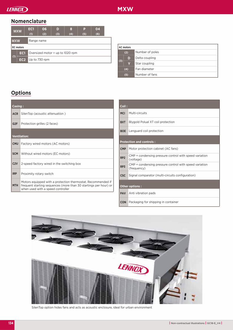
MXW EC1 06 D 8 P 04(1) (2) (3) (4) (5) (6)
MXW
(1)EC1
EC2
ACR
G2F
CMU
SCM
C2V
IRP
MTH
MCI
BXT
BOE
CMP
RP2
RP3
CSC
PAV
CON
(2)
(3)DY
(4)
(5)
MXW
134 | Non-contractual illustrations | GC18-E_V4 |
Nomenclature
Range name
EC motors
Oversized motor = up to 1020 rpm
Up to 730 rpm
Options
Casing :
SilenTop (acoustic attenuation )
Protection grilles (2 faces)
Ventilation:
Factory wired motors (AC motors)
Without wired motors (EC motors)
2-speed factory wired in the switching box
Proximity rotary switch
Motors equipped with a protection thermostat. Recommended if frequent starting sequences (more than 30 startings per hour) or when used with a speed controller
Coil :
Multi-circuits
Blygold Polual XT coil protection
Lenguard coil protection
Protection and controls :
Motor protection cabinet (AC fans)
CMP + condensing pressure control with speed variation (voltage)
CMP + condensing pressure control with speed variation (frequency)
Signal comparator (multi-circuits confi guration)
Other options :
Anti vibration pads
Packaging for shipping in container
SilenTop option hides fans and acts as acoustic enclosure, ideal for urban environment
AC motors
Number of poles
Delta coupling
Star coupling
Fan diameter
Number of fans

135
|
ALLEGRA0,6 6,7 kW / 105 1500 m3/h 136
|
COMFAIR HD1,2 4 kW / 230 620 m3/h 141
|
COMFAIR HH/HV2,8 61 kW / 840 8000 m3/h 144
|
ARIA 21,3 6,6 kW / 290 1080 m3/h 148
|INALTO2,6 28 kW / 380 5670 m3/h 152
|
ARMONIA / ARMONIA EC1,3 11 kW / 310 1820 m3/h 157
| 163
|
CLEANAIR LX1 000 100 000 m3/h 165
|
AXI L • EQUITHERM12 105 kW 168
| Non-contractual illustrations | GC18-E_V4 |
Airside products
Fan coil unit
High wall fan coil unit
High pressure modular fan coil unit
Ductable fan coil unit with EC fan
Ductable air treatment unit
Chilled water cassette
Remote controls and communicating controllers
Modular air handling unit
Unit heater • Destratifier fan

136
ALLEGRA
D I R E C T I V E 2 0 0 9 / 1 2 5 / E C
ECODESIGN
ErP
Cooling capacity:0,6 - 6,7 kW
Airfl ow rate:105 - 1500 m3/h
FAN COIL UNIT
Range of fan coil with innovative designs
Noise performance among the best on the market
eDrive EC motor for comfort and energy saving
Sober and attractive design
LENNOX participates in the ECP programme for FCU.
Check ongoing validity of certifi cate :www.eurovent-certifi cation.com

ALLEGRA0,6 6,7 kW105 1500 m3/h
137| Non-contractual illustrations | GC18-E_V4 |
Main applications• Offi ce buildings• Hotels
Fan coil unit
DESCRIPTION : One of the most versatile ranges of fan coils on the
market 9 sizes - 4 diff erent versions :
Wall and ceiling mounted unitsExposed or concealed with centrifugal fan 9 fl ow rates (5 sizes with EC motor) 3 or 4 row coil and with the possibility to add a 1 or 2 row
coil for 4-pipe systems Meet all air-conditioning requirements of work environ-
ments like offi ces, shops, restaurants and hotel rooms featuring ducted installations with available pressure up to 40 Pa Control : Available fi tted on the unit, remote wall mounted,
or infra-red with also master-slaves and BMS possibility in the diff erent common protocols
MAIN COMPONENTS :
D
MM
Cabinet : Galvanized and pre-painted steel casing. Plastic top grid with fi xed louvres is reversible in order to distribute the air in two diff erent directions Frame : galvanized steel with closed cell insulation Filter : Polypropylene cellular fabric regenerating fi lter with
galvanized steel frame The fans :
Aluminium or plastic blades directly keyed on the motor with double aspiration
Dynamically and statically balanced AC motor :
Wired for single-phase Six speeds, three of which are connected. Motor fi tted on sealed for life bearings and secured on anti-vibration and self-lubricating mountings. Internal thermal protection with automatic reset, Protection IP 20, class B EC motor : Three phase permanent magnet brushless elec-
tronic motor. 230 Volt, single-phase Coil :
Copper tube and the aluminium fi ns. Pipe connections on the left or right side. May be modify easily on site during installation Condensate collection tray : made from plastic with an
“L”-shape fi tted on the inner casing
ACCESSORIES : 3-way or 2-way valve ON/OFF fi tted Electric heater with integral: safety thermostat and relay
control Extension condensate collection tray Feet Fresh air mixing damper (can be motorized) Rear and Bottom closing panel(unit with cabinet) Frame for wall concealed installation Straight and 90° inlet and outlet fl ange Air inlet grid with or without fi lter Spigot plenum for return and discharge Auxiliary drain pan Condensate drain pump
AA

138
ALLEGRA
MIN MED MAX
(*)
ALLEGRA 100 200 300 400 5001 4 6 1 3 5 2 3 5 2 3 5 2 4 6
MIN MED MAX MIN MED MAX MIN MED MAX MIN MED MAX MIN MED MAX
m3/h 105 175 220 145 220 295 235 270 385 265 335 485 315 495 650
kW
0,57 0,84 1,00 0,9 1,23 1,53 1,55 1,76 2,35 1,71 2,11 2,83 2,01 2,9 3,13
0,45 0,69 0,83 0,68 0,95 1,21 1,13 1,3 1,76 1,26 1,57 2,15 1,49 2,19 2,38
0,64 0,98 1,19 0,94 1,34 1,7 1,56 1,79 2,44 1,74 2,18 2,97 2,02 3,0 3,24
0,55 0,77 0,91 0,83 1,09 1,33 1,4 1,56 1,99 1,52 1,81 2,33 1,84 2,5 2,66
kPa
2,5 4,7 6,3 2,5 4,4 6,5 9,4 11,8 19,7 11,2 16,2 27,2 5,8 11,1 12,7
1,0 1,8 2,5 2,2 4,2 6,4 7,8 10,0 17,1 9,5 14 24,3 5,0 9,6 11,0
0,5 1,0 1,3 1,3 2,2 3,1 4,2 5,1 7,8 4,9 6,6 10,3 1,3 2,3 2,6
W 16 25 33 14 22 32 20 25 41 21 28 44 22 39 46
dB(A) 23 30 36 21 31 38 27 31 40 24 30 38 22 32 39
ALLEGRA 200 400 600 700 900V 1 5 10 1 5 10 1 5 10 1 5 10 1 5 10
MIN MED MAX MIN MED MAX MIN MED MAX MIN MED MAX MIN MED MAX
m3/h 120 220 330 210 350 515 305 495 735 400 610 890 605 945 1395
kW
0,73 1,18 1,59 1,41 2,18 2,95 1,96 2,93 3,96 2,6 3,68 4,94 3,45 4,82 6,26
0,55 0,92 1,28 1,03 1,64 2,26 1,46 2,22 3,08 1,92 2,77 3,8 2,63 3,79 5,1
0,77 1,29 1,8 1,42 2,26 3,14 1,96 3,0 4,14 2,56 3,72 5,08 3,74 5,41 7,38
0,71 1,08 1,43 1,29 1,85 2,41 1,76 2,45 3,22 2,33 3,13 4,06 2,99 4,05 5,24
kPa
2,2 5,0 8,6 7,9 17,0 28,9 5,5 11,1 19 10,5 19,4 32,6 8,9 16,1 25,9
2,3 5,4 9,4 7,3 16,0 28,1 6,4 13,2 23,3 9,7 18,4 31,8 8,9 16,1 25,9
1,6 3,9 7,0 6,6 14,9 26,7 4,5 9,6 17,0 8,5 16,4 28,3 7,3 14,0 24,2
1,0 2,1 3,5 3,6 6,9 11,0 1,2 2,2 3,6 2,4 4,0 6,3 3,7 6,3 9,9
W 7,0 11,0 21,0 6,0 12,0 25,0 7,0 15,0 32,0 9,0 19,0 41,0 16,0 41,0 99,0
dB(A) 21 32 42 21 33 42 24 35 45 28 39 48 35 46 55
ALLEGRA 600 700 800 9001 3 5 2 4 6 2 4 6 2 4 6
MIN MED MAX MIN MED MAX MIN MED MAX MIN MED MAX
m3/h 415 590 760 535 735 925 655 1020 1200 830 1210 1500
kW
2,5 3,32 4,01 3,29 4,21 5,01 3,68 5,09 5,69 4,38 5,74 6,56
1,87 2,54 3,12 2,45 3,19 3,85 2,82 4,02 4,55 3,4 4,6 5,37
2,56 3,45 4,26 3,34 4,33 5,23 4,02 5,75 6,55 4,86 6,62 7,78
2,19 2,79 3,33 2,89 3,59 4,2 3,16 4,26 4,75 3,71 4,79 5,46
kPa
8,6 14,1 19,8 16,2 25,1 34,2 10,3 18,4 22,5 13,8 22,4 28,6
7,5 12,3 17,8 13,5 21,3 29,7 8,3 15,6 19,6 11,6 19,9 26,5
1,8 2,8 3,8 3,5 5,1 6,7 4,1 6,9 8,3 5,4 8,5 10,7
W 37 55 78 54 79 103 62 105 130 92 134 176
dB(A) 28 37 43 33 42 47 36 47 51 41 49 55
| Non-contractual illustrations | GC18-E_V4 |
Operating conditions :Air inlet 27°C DB/19°C WB – Chilled water 7/12°C
Air inlet 20°C - 2-pipe unit : hot water inlet = 50°C – 4-pipe unit : hot water = 70/60°C
Standard connected speeds
Minimum speed Average speed Maximum speedThe sound pressure levels are 9 dB(A) lower than the sound power levels and apply to the reverberant fi eld of a 100 m3 room and a reverberation time of 0.5 sec.
General data3-row coil - AC motor
3-row coil - EC motor
Speed
Airfl ow rate
Total cooling capacity
Sensible cooling capacity
Heating capacity2 pipes
4 pipes (1 row)
Dp cooling
Dp heating2 pipes
4 pipes (1 row)
Fan
Sound pressure (*)
Inverter powerSpeed
Airfl ow rate
Total cooling capacity
Sensible cooling capacity
Heating capacity2 pipes
4 pipes (1 row)
Dp cooling2 pipes
4 pipes (1 row)
Dp heating2 pipes
4 pipes (1 row)
Fan
Sound pressure (*)
Speed
Airfl ow rate
Total cooling capacity
Sensible cooling capacity
Heating capacity2 pipes
4 pipes (1 row)
Dp cooling
Dp heating2 pipes
4 pipes (1 row)
Fan
Sound pressure (*)
Check ongoing validity of certifi cate :eurovent-certifi cation.com
139
ALLEGRA
ALLEGRA 100 200 300 400 500
1 4 6 1 3 5 2 3 5 2 3 5 2 4 6
MIN MED MAX MIN MED MAX MIN MED MAX MIN MED MAX MIN MED MAX
m3/h 105 175 220 145 220 295 235 270 385 265 335 485 315 495 650
kW
0,65 1,0 1,2 1,0 1,41 1,78 1,63 1,87 2,53 1,81 2,25 3,08 2,17 3,21 3,49
0,49 0,77 0,94 0,73 1,05 1,35 1,18 1,36 1,86 1,32 1,65 2,3 1,58 2,36 2,58
0,69 1,07 1,31 0,99 1,43 1,83 1,62 1,87 2,59 1,8 2,27 3,14 2,1 3,16 3,46
kPa1,9 4,0 5,6 4,9 9,2 13,9 5,3 6,7 11,5 6,1 9,0 15,5 10,4 20,8 31,3
1,7 3,7 5,3 4,0 7,6 11,8 4,2 5,4 9,8 5,0 7,2 12,8 8,1 16,6 19,5
W 16 25 33 14 22 32 20 25 41 21 28 44 22 39 46
dB(A) 23 30 36 21 31 38 27 31 40 24 30 38 22 32 39
ALLEGRA 600 700 800 900
1 3 5 2 4 6 2 4 6 2 4 6
MIN MED MAX MIN MED MAX MIN MED MAX MIN MED MAX
m3/h 415 590 760 535 735 925 655 1020 1200 830 1210 1500
kW
2,79 3,81 4,71 3,51 4,56 5,48 3,97 5,63 6,34 4,79 6,41 7,42
2,03 2,81 3,52 2,57 3,39 4,13 2,98 4,33 4,93 3,63 4,98 5,87
2,82 3,9 4,92 3,49 4,62 5,59 4,26 6,27 7,2 5,23 7,18 8,52
kPa14,4 24,8 36,2 12,5 20,0 27,7 7,6 14,1 17,5 10,6 17,8 23,2
12,0 21,1 31,8 10,1 16,6 23,2 13,8 27,6 35,2 10,0 17,6 23,7
W 37 55 78 54 79 103 62 105 130 92 134 176
dB(A) 28 37 43 33 42 47 36 47 51 41 49 55
ALLEGRA 200 400 600 700 900
V 1 5 10 1 5 10 1 5 10 1 5 10 1 5 10
MIN MED MAX MIN MED MAX MIN MED MAX MIN MED MAX MIN MED MAX
m3/h 115 210 325 200 340 505 290 475 720 380 585 875 575 910 1365
kW
0,77 1,32 1,86 1,43 2,27 3,17 2,05 3,19 4,51 2,61 3,82 5,3 3,59 5,21 7,04
0,56 0,98 1,42 1,03 1,67 2,39 1,48 2,34 3,38 1,9 2,82 3,99 2,69 3,99 5,53
0,78 1,37 1,98 1,42 2,3 3,32 2,02 3,23 4,68 2,57 3,84 5,43 3,76 5,63 7,93
kPa3,2 8,0 14,8 4,0 8,9 16,1 8,2 17,8 33,0 7,3 14,3 25,6 6,3 12,1 20,8
2,6 7,1 13,6 3,2 7,6 14,7 6,6 15,1 29,1 5,9 12,0 22,0 5,6 11,4 20,9
W 7,0 11,0 21,0 6,0 12,0 25,0 7,0 15,0 32,0 9,0 19,0 41,0 16,0 41,0 99,0
dB(A) 21 32 42 21 33 42 24 35 45 28 39 48 35 46 55
MIN MED MAX
(*)
| Non-contractual illustrations | GC18-E_V4 |
4-row coil - AC motor - 2-pipe units
4-row coil - EC motor - 2-pipe units
Speed
Airfl ow rate
Total cooling capacity
Sensible cooling capacity
Heating capacity
Dp cooling
Dp heating
Fan
Sound pressure (*)
Speed
Airfl ow rate
Total cooling capacity
Sensible cooling capacity
Heating capacity
Dp cooling
Dp heating
Fan
Sound pressure (*)
Inverter power
Speed
Airfl ow rate
Total cooling capacity
Sensible cooling capacity
Heating capacity
Dp cooling
Dp heating
Fan
Sound pressure (*)
Check ongoing validity of certifi cate :eurovent-certifi cation.com
Operating conditions :Air inlet 27°C DB/19°C WB – Chilled water 7/12°C
Air inlet 20°C - 2-pipe unit : hot water inlet = 50°C – 4-pipe unit : hot water = 70/60°C
Standard connected speeds
Minimum speed Average speed Maximum speedThe sound pressure levels are 9 dB(A) lower than the sound power levels and apply to the reverberant fi eld of a 100 m3 room and a reverberation time of 0.5 sec.

ALLEGRA
ALLEGRA 100 200 300 400 500 600 700 800 900
A
mm
675 775 990 990 1205 1205 1420 1420 1420
B 225 225 225 225 225 225 225 255 255
C 374 474 689 689 904 904 1119 1119 1119
D 218 218 218 218 218 218 218 248 248
E 205 205 205 205 205 205 205 235 235
kg
13,9 15,4 19,1 20,2 24,1 24,9 28,8 32 32,2
14,6 16,2 20,3 21,4 25,6 26,4 30,6 33,8 34
15,1 16,8 21 22,1 26,5 27,3 31,7 34,9 35,1
14,4 16,2 20,1 21,2 25,3 26,2 30,3 33,5 33,7
15,1 17 21,3 22,4 26,8 27,7 32,1 35,3 35,5
B
170A
100
530
630
511
C22 22
2910012 12
D
E
Ø 15 ext.
230
140 | Non-contractual illustrations | GC18-E_V4 |
Dimensions and weights
Condensate tray (option)
Weight - Without cabinet
3 rows
3 + 1 rows
3 + 2 rows
4 rows
4 + 1 rows
Cased units
Chassis units

141
COMFAIR HD
D I R E C T I V E 2 0 0 9 / 1 2 5 / E C
ECODESIGN
ErP
Cooling capacity:1,2 - 4 kW
Airfl ow rate:230 - 620 m3/h
HIGH WALL FAN COILS UNIT
Modern design and innovative technical features designed for quality and room enhancement
Tangential fan that off ers the maximum acoustic comfort
Display Integrated in the cover cabinet shows the set-up of the unit
An innovative solution including valve allows an easier
LENNOX participates in the ECP programme for FCU.Check ongoing validity of certifi cate :
www.eurovent-certifi cation.com

142
COMFAIR HD1,2 4 kW230 620 m3/h
| Non-contractual illustrations | GC18-E_V4 |
Main applications• Offi ce buildings• Residential buildings
High wall fan coils unit
Description : Consistent range with a tangential fan Four diff erent sizes in 2 pipes Maximum acoustic comfort,
Main components : Tangential fan :
Designed to reach high capacities at low motor speed, Copper tubes and aluminium fi ns coil with hydrophilic
treatment : avoid any risk of water dragging and corrosion Easily reachable air vent : directly discharging in the
condensate drain pan Integrated valve supplied as standard :
Effi ciently avoid waste of energy, because the water fl ow is stopped when the unit is off Easy installation, without requiring any niche in the wall
DD
MM
Control : Display integrated in the cover cabinet : shows room
temperature, fan speed and running mode. Remote control : comfortable and intuitive, its minimal
and ergonomic design enhances its functionality and handiness. Automatic swing : complete control of the airfl ow
through the remote control, ensuring maximum room comfort Sleep mode : Activating this mode sets automatically
temperature and fan speed to ensure the maximum comfort, noiselessness and low cost. Real time programmable timer : allowing to program
(within 24 hours) the startup and shutdown of the unit, in a completely automatic way even in your absence, so that you will fi nd the right room comfort at your arrival.
CCDi

143
COMFAIR HD 1 2 3 4
MIN MED MAX MIN MED MAX MIN MED MAX MIN MED MAX
(1)
W1550 1730 1960 1830 2100 2380 2420 2960 3340 2920 3640 4000
1170 1330 1520 1410 1640 1900 1890 2320 2680 2260 2850 3130
l/h 266 297 336 314 359 409 415 508 573 501 625 686
kPa 10 12,5 15,9 14,3 18,3 22,9 9,7 11,3 14,8 11,8 17,8 21,6
(2)
W 1880 2110 2420 2280 2610 2970 3000 3800 4390 3860 4450 4920
l/h 266 297 336 314 359 409 415 508 573 501 625 686
kPa 9,3 11,6 15 13 16,4 20,5 8,3 13,8 17,3 10,6 15,9 19,8
(3)
W 3390 3810 4390 3850 4400 5030 5070 6450 7480 6540 7500 8280
l/h 298 334 386 338 386 442 445 566 657 574 659 727
kPa 10,9 13,8 18,4 14,1 17,7 22,4 8,8 16 21,1 13,1 16,9 21,2
m3/h 234 282 344 273 333 417 375 476 553 426 544 620
dB(A)47 50 53 45 50 54 43 50 54 45 52 56
38 41 45 37 41 45 34 41 45 37 44 48
W 25 26 29 25 27 29 35 42 48 35 45 51
A 0,11 0,12 0,13 0,11 0,12 0,13 0,17 0,22 0,26 0,18 0,24 0,30
I 0,81 0,85 1,24 1,85
COMFAIR HD 1 2 3 4
L
mm
880 990 1172 1172
H 298 305 360 360
P 205 210 220 220
kg 11,5 12,4 19 20,5
(1) (2) (3)
P L
H
| Non-contractual illustrations | GC18-E_V4 |
General data
Speed
Total cooling capacity
Sensible cooling capacity
Water fl ow
Water pressure drop
Heating capacity
Water fl ow
Water pressure drop
Heating capacity
Water fl ow
Water pressure drop
Air fl ow rate
Sound power level
Sound pressure level
Power supply 230V/50Hz
Power input
Absorbed current
Water content
Weight
Cooling mode : Heating mode : Heating mode :
Inlet water temperature = 7°C Air temperature = 20°C Air temperature = 20°C
Outlet water temperature = 12°C Inlet water temperature = 50°C Inlet water temperature = 70°C / 60°C
Inlet air temperature : 27°C DB/19°C WB
• Standard unit with free outlet: external static pressure = 0 Pa
• Sound power level: ISO 23741
• Sound pressure level: 8,6 dB(A) lower that the sound power level for a room of 90 m3 with a reverberation time of 0,5 sec.
• Supported power supply: ~230V±10%/1 Ph/50 Hz
Dimensions and weights
Check ongoing validity of certifi cate :eurovent-certifi cation.com

COMFAIR HH/HV
D I R E C T I V E 2 0 0 9 / 1 2 5 / E C
ECODESIGN
ErP
Cooling capacity:2,8 - 61 kW
Airfl ow rate:840 - 8000 m3/h
HIGH PRESSURE FAN COIL UNIT
Very high performances
Easy and quick to install like a fan coil
LENNOX participates in the ECP programme for FCU.Check ongoing validity of certifi cate :
www.eurovent-certifi cation.com
Sizes 60 & 70 non subject to the ErP directive

COMFAIR HH/HV2,8 61 kW840 8000 m3/h
145| Non-contractual pictures | GC18-E_V1 |
Main applications• Small size commercial building• Offi ces buildings• Food and non food retail• Hotels
High pressure fan coil unit
Description : Centrifugal high pressure fan coils Available in
7 capacity sizes, Vertical (HV) or horizontal (HH) confi guration, 2 and 4 pipe systems or 2 pipe system with additional electric heater.
Main components : Main structure in galvanized sheet metal, 1 mm
thickness, with insulation Heat exchanger condensate drain pan and drainage fi ttings supplied as standard Ventilation group factory tested. One or two dual inlet
centrifugal fans with horizontally extending aluminium blades; static and dynamical balancing. Single phase asynchronous electric motor with overload cut-off . Copper tubes heat exchanger, expanded into
aluminium fi ns. Male fi ttings and standard air vents. Left side water connection as standard, right side on request.
DD
MM
Accessories : Internal or external thermal or/and acoustic insulation G3 or activated carbons G2 fi lters Coils with diff erent row numbers (4, 5 or 6 row coils, 1
or 2 row auxiliary coils) Direct expansion coils Electric heaters (from 3 to 24 kW) 2 and 3 way regulation valves, 230 ON/OFF, 24V ON/
OFF, 24V 3 points, 24 V 0-10V Manual or motorized fresh air dampers Condensate drain pumps Straight or 90° supply or return plenums with or
without spigots, antivibrating joints, connecting fl anges Supply or return aluminium diff users (with or without fi lters) Wide range of remote controls Non standard units built on customer request
AAI

COMFAIR HH/HV
COMFAIR HH/HV 10 20 30 40 50 60 70
1 2,18 3,30 5,26 5,75 6,67 15,3 29,2
2 2,20 4,10 6,22 7,13 8,40 17,4 32,8
3 2,30 4,34 6,51 7,51 9,60 18,4 34,4
1 2,83 4,50 7,39 7,40 8,32 20,8 38,4
2 2,90 5,30 7,80 8,98 11,5 23,3 2,9
3 3,09 5,60 8,26 9,40 13,1 24,6 44,8
1 3,60 5,30 8,35 8,80 10,5 24,0 51,9
2 3,70 6,31 9,40 10,8 14,4 27,2 50,9
3 3,97 6,70 10,0 11,2 16,5 28,8 53,2
531 1051 1531 1616 2253 4231 7705
1 13,1 17,2 22,2 16,5 13,3 21,1 28,0
2 14,2 23,2 22,5 25,3 20,8 25,3 27,2
3 15,3 26,9 31,4 27,8 26,0 27,7 29,3
1 11,0 14,4 18,5 13,9 11,2 17,4 18,6
2 12,0 19,5 19,7 21,2 17,6 20,5 22,4
3 13,0 22,6 26,1 23,3 22,0 22,6 23,9
3 6 6 9 9 12 18
4,5 9 9 12 12 18 24
1 570 737 1293 1262 1480 3102 6193
2 610 940 1627 1728 2163 3645 7248
3 650 1064 1764 1780 2650 3946 7731
1 54 51 57 57 54 64 65
2 57 56 61 61 57 69 70
3 60 57 63 62 60 74 75
1 58 55 60 60 59 61 62
2 61 58 65 64 61 66 67
3 64 61 67 66 65 70 72
1 35 35 31 35 35 67 77
2 50 50 50 50 50 100 100
3 60 60 59 60 60 122 121
146 | Non-contractual illustrations | GC18-E_V4 |
Data given at medium speed - 50 Pa available static pressure, except for sizes 60 & 70 : 100 Pa available static pressure.(1) Cooling: Water inlet temperature: 7°C; water outlet temperature: 12°C; air inlet temperature: 27°C D.B - 19°C W.B(2) Heating: Water inlet temperature: 50°C; water fl ow rate as in cooling mode; air inlet temperature: 20°C(3) Sound power level: according to ISO 23741
General data
Speed
2 pipe system (3 row coil for HH/HV 10-50 - 4 row coil for HH/HV 60-70)
Cooling capacity (1)
Sensible
kWTotal
Heating capacity (2)
Water fl ow l/h
Water pressure drop
Cooling
kPa
Heating
Electrical heaterStandard
kWHigh
Airfl ow rate m3/h
Sound power level (3)
Suction + radiated
dB(A)
Air supply
Available static pressure/Maximum external static pressure (50% performance reduction)
2 pipes system Pa
Check ongoing validity of certifi cate :eurovent-certifi cation.com

COMFAIR HH/HV 10 20 30 40 50 60 70
3 3 3 3 3 4 4
1/2" 1/2" 3/4" 3/4" 1" 1" 1/4 1" 1/2
1 1 1 1 1 2 2
1/2" 1/2" 1/2" 1/2" 3/4" 1" 1" 1/4
Ø mm 20 20 20 20 20 20 20
mm
650 1000 1100 1339 1339 1341 2028
533 533 533 533 533 853 853
299 299 324 324 374 674 674
kg 28 36 41 46 57 117 192
A B
C
COMFAIR HH/HV 10 20 30 40 50 60 70
1
kW
2,38 3,45 5,07 5,40 6,34 14,3 26,7
2 2,36 3,94 6,00 6,70 7,54 15,9 30,1
3 2,40 4,34 6,70 6,95 9,65 17,0 32,0
1 2,75 4,50 5,50 6,60 8,47 18,3 33,3
2 2,86 5,07 6,34 8,10 9,97 20,2 37,3
3 2,87 6,11 8,10 8,44 12,3 21,5 39,5
1 3,23 4,70 6,73 7,80 8,15 29,4 52,8
2 3,37 5,90 8,00 9,10 9,50 31,9 58,1
3 3,40 6,20 8,25 9,45 11,50 33,7 61,0
l/h(1) 494 1051 1394 1451 2116 3698 6794
l/h(3) 292 534 710 814 990 2900 5246
1
kPa
13,4 15,0 19,9 21,7 13,2 16,0 52,8
2 14,8 19,0 22,0 25,9 17,5 18,9 58,1
3 15,4 26,9 31,5 37,9 25,8 21,0 61,0
1 17,7 8,00 21,0 9,50 12,4 13,4 14,8
2 19,5 11,1 29,0 11,4 16,3 15,6 17,7
3 20,3 13,0 23,7 15,9 23,0 17,6 19,6
1m3/h
580 850 1180 1460 1470 2905 5613
2 631 1014 1461 1700 1860 3308 6570
3 654 1065 1750 2400 2640 3623 7143
1
dB(A)
54 52 57 54 58 64 65
2 56 56 60 56 65 69 70
3 60 57 63 60 69 74 75
1 58 55 62 58 58 61 62
2 60 60 64 60 66 66 67
3 64 61 68 64 69 70 72
1Pa
35 35 35 35 25 68 80
2 50 50 50 50 50 100 100
3 60 60 60 50 60 123 125
COMFAIR HH/HV
147| Non-contractual illustrations | GC18-E_V4 |
Dimensions and weights
Standard coilNumber of rows
Connections Ø
Auxiliary coilNumber of rows
Connection Ø
Drain connection (out)
A
B
C
Net weight
Data given at medium speed - 50 Pa available static pressure, except for sizes 60 & 70 : 100 Pa available static pressure.(1) Cooling: Water inlet temperature: 7°C; water outlet temperature: 12°C; air inlet temperature: 27°C D.B - 19°C W.B(2) Heating: Water inlet temperature: 70°C; water outlet temperature: 60°C; air inlet temperature: 20°C(3) Sound power level: according to ISO 23741
Speed
4 pipe system (3 +1 row coil for HH/HV 10-50 - 4+2 row coil for HH/HV 60-70)
Cooling capacity (1)
Sensible
Total
Heating capacity (2)
Water fl owCooling
Heating
Water pressure drop
Cooling
Heating
Airfl ow rate
Sound power level (3)
Air suction + radiated
Air supply
Available static pressure/Maximum external static pressure (50% performance reduction)
4 pipes system
General data Check ongoing validity of certifi cate :eurovent-certifi cation.com

ARIA 2
D I R E C T I V E 2 0 0 9 / 1 2 5 / E C
ECODESIGN
ErP
Cooling capacity:1,3 - 6,6 kW
Airfl ow rate:290 - 1080 m3/h
DUCTABLE FAN COIL UNITWITH EC FAN
Low energy consumption
Easy maintenance
Low noise
Reliability

ARIA 21,3 6,6 kW
149| Non-contractual illustrations | GC18-E_V4 |
Main applications• Offi ce buildings• Hotels
High pressure ductable fan coilWith EC fan
Description : Horizontal ducted fan coil unit for installations
requiring medium to high static pressure Available in
4 sizes,2 or 4 pipes,standard or low noise execution
9 airfl ow confi gurations available.
Main components : Main structure in galvanized steel, 10/10 mm
thickness with internal insulation (10 mm polyurethane foam EN 13501-1 Euroclass B-s2, d0 / BL-s1, d0)
Water coil (copper with aluminum fi ns) provided with manual air vent
Single or double direct driven centrifugal fan with brushless motor (EC fan)
Galvanized drain pan Mounting brackets G2 fi lter Built-in silencer (in low noise execution)
DD
MM
Accessories : G1 metallic fi lter or G3 or G4 fi lter Auxiliary coil for 4 pipe installation 2 or 3 way valve ON/OFF or 24V 3points or
modulating 24V 0-10V Fresh air connection 100 or 125mm Auxiliary condensate drain pan Condensate drain pump Stand alone or communicating controls
AAG

150
ARIA 2
213 216 223 2263 6 3 6
m3/h490 480 1090 1080390 380 890 880290 280 690 680
Pa76 65 75 6550 50 50 5027 27 30 30
W1760 2850 4270 66201550 2430 3810 57301300 1940 3270 4740
W1520 2200 3540 50301300 1830 3090 42801060 1430 2580 3470
l/h302 490 734 1138266 418 655 984223 334 563 815
kPa6 9 20 105 7 17 84 5 13 6
W2540 3750 5940 85302190 3110 5190 72501790 2420 4360 5860
l/h302 490 734 1138266 418 655 984223 334 563 815
kPa7 10 16 115 8 14 84 5 10 6
dB(A)63 63 67 6760 60 65 6552 52 62 62
dB(A)61 61 66 6658 58 63 6348 48 60 60
413 416 423 4263 6 3 6
2 2 2 2
W3190 3190 7700 77002750 2750 6760 67602250 2250 5710 5710
l/h279 279 673 673241 241 591 591196 196 499 499
kPa4 4 26 263 3 21 212 2 16 16
| Non-contractual illustrations | GC18-E_V4 |
2 pipes
Fan speedNumber of rows
Air fl ow rateMaximum
Average
Minimum
Static pressureMaximum
Average
Minimum
Cooling mode
Total cooling capacity (1)
Maximum
Average
Minimum
Sensible cooling capacity (1)
Maximum
Average
Minimum
Water fl ow rateMaximum
Average
Minimum
Pressure dropMaximum
Average
Minimum
Heating mode
Heating capacity (2)
Maximum
Average
Minimum
Water fl ow rateMaximum
Average
Minimum
Pressure dropMaximum
Average
Minimum
Acoustic data
Sound power levelAir suction + Radiated
Maximum
Average
Minimum
Sound power level Air supply
Maximum
Average
Minimum
4 pipes
Fan speed
Number of rows (main coil)
Number of rows (auxiliary coil)
Heating mode
Heating capacity (2)
Maximum
Average
Minimum
Water fl ow rateMaximum
Average
Minimum
Pressure dropMaximum
Average
Minimum
General data
(1) Cooling mode : Water inlet temperature: 7°C Water outlet temperature: 12°C Air inlet temperature : 27°C DB / 19 °C WB
(2) Heating mode : Air temperature: 20°C Water inlet temperature: 50°C

151
1050
69
69
482
241
1050
69
69
882
241
ARIA 2213-216 / 413-416
ARIA 2223-226 / 423-426
ARIA 2 : 213-216 / 413-416 ARIA 2 : 223-226 / 423-426
ARIA 2 213 216 223 226 413 416 423 426
33 35 50 55 41 43 60 65
50 52 71 76 58 68 89 94
11
12
13
21
22
23
31
32
33
L R
11
12
13
21
22
23
31
32
33
L R
ARIA 2
| Non-contractual illustrations | GC18-E_V4 |
Air supply confi gurations
Dimensions and weights
2 pipes 4 pipes
WeightStandard unit
WeightLow noise unit
Water connections
Water connections
Water connections Water connections

INALTO
D I R E C T I V E 2 0 0 9 / 1 2 5 / E C
ECODESIGN
ErP
Cooling capacity:2,6 - 28 kW
Airfl ow rate:380 - 5670 m3/h
DUCTABLE AIR TREATMENT UNIT
High performances
Modularity
Easy and quick to install
Easy maintenance,
Reliability,
Low energy consumption (EC version)
LENNOX participates in the ECP programme for FCU.Check ongoing validity of certifi cate :
www.eurovent-certifi cation.com

INALTO2,6 28 kW
INALTO-VINALTO-DS-V
INALTO-HINALTO-DS-H
153| Non-contractual illustrations | GC18-E_V4 |
Ductable air treatment unit
Main applications• Small size commercial buildings• Offi ce buildings• Food and non-food retail• Hotels
Description : High pressure ductable air treatment unit for
installations requiring medium to high static pressure Available in
7 sizes,Horizontal (H) or Vertical (V) installation 2 or 4 pipes,With EC or AC fanSingle or double skin version
Reduced height for installation in suspended ceiling (horizontal version).
Main components : Main structure in galvanized steel, 10/10 mm
thickness with internal insulation (10 mm polyurethane foam EN 13501-1 Euroclass B-s2, d0 / BL-s1, d0)
Double skin panels, 15 mm thickness in galvanized steel inside, white pre-painted galvanized steel outside. Thermal and sound insulation with 35 kg/m3 density mineral wool (double skin version only).
Water coil (copper with aluminum fi ns) provided with manual air vent.
Double direct driven centrifugal fan (with EC or AC motor).
Galvanized drain pan
DD
MM
Accessories : G3 or G4 fi lter Auxiliary coil for 4 pipe installation 6 rows main coil 2 or 3 way valve ON/OFF or 24V 3 points or
modulating 24V 0-10V Electric heating section (4,5 to 19,2 kW) Humidifi cation section Supply and air return plenums Fresh air connection 100 or 125 mm Auxiliary condensate drain pan Condensate drain pump Stand alone or communicating controls
AAG

154
INALTO
05 11 15 25 28 49 57
m3/h516 1039 1528 1946 2806 4916 5668484 1007 1267 1470 2349 4357 4776381 939 1092 976 1997 3161 4027
Pa57 55 73 88 72 63 7250 50 50 50 50 50 5039 44 37 22 37 26 37
W2987 6058 9016 11274 15131 24480 278512856 5924 7825 9140 13329 22568 248182581 5618 6966 6630 11810 17979 22020
W2256 4388 6506 8144 11081 18260 208012147 4284 5585 6490 9649 16688 183081926 4048 4926 4640 8470 13039 16050
l/h530 1065 1590 1994 2695 4348 4976506 1041 1380 1614 2373 4003 4430457 988 1229 1171 2103 3182 3931
kPa10,8 14,6 18,6 18 21 21,1 28,99,9 14,1 14,5 12,4 16,8 18,2 22,88,3 12,8 11,8 7 13,6 12,1 18,1
W3760 7830 11560 14600 20030 33210 377403570 7640 9930 11640 17440 30310 331903240 7220 8790 8260 15330 23620 29110
l/h529 1062 1585 1994 2687 4348 4960504 1038 1377 1614 2365 4003 4416459 984 1225 1171 2098 3182 3918
kPa9,2 11,9 15,2 14,6 17,1 17,1 23,28,3 11,5 11,8 10,1 13,6 14,8 18,96,7 10,4 9,6 5,7 11 9,9 15,3
dB(A)
62 68 63 64 70 72 7460 67 59 58 67 69 7056 67 55 55 63 61 6661 65 66 66 71 74 7559 64 60 59 66 70 6955 64 57 56 62 61 6553 59 54 55 61 63 6551 58 50 49 58 60 6147 58 46 46 54 52 5752 56 57 57 62 65 6650 55 51 50 57 61 6046 55 48 47 53 52 5661 64 66 67 71 74 7559 63 60 58 66 70 6955 64 57 53 62 61 6561 64 66 67 71 74 7559 63 60 58 66 70 6955 64 57 53 62 61 6552 55 57 58 62 65 6650 54 51 49 57 61 6046 55 48 44 53 52 5652 55 57 58 62 65 6650 54 51 49 57 61 6046 55 48 44 53 52 56
| Non-contractual illustrations | GC18-E_V4 |
2 pipes (4 rows coil) Fan speed
Air fl ow rateMaximum
Average
Minimum
Static pressureMaximum
Average
Minimum
Cooling mode
Total cooling capacity (1)
Maximum
Average
Minimum
Sensible cooling capacity (1)
Maximum
Average
Minimum
Water fl ow rateMaximum
Average
Minimum
Water pressure dropMaximum
Average
Minimum
Heating mode
Heating capacity (2)
Maximum
Average
Minimum
Water fl ow rateMaximum
Average
Minimum
Pressure dropMaximum
Average
Minimum
Acoustic data
INA
LTO
Sin
gle
ski
n un
it
Sound power levelAir suction + radiated
Maximum
Average
Minimum
Sound power levelAir supply
Maximum
Average
Minimum
Sound pressure levelAir suction + radiated
Maximum
Average
Minimum
Sound pressure levelAir supply
Maximum
Average
Minimum
INA
LTO
Do
uble
ski
n un
it
Sound power levelAir suction + radiated
Maximum
Average
Minimum
Sound power levelAir supply
Maximum
Average
Minimum
Sound pressure levelAir suction + radiated
Maximum
Average
Minimum
Sound pressure levelAir supply
Maximum
Average
Minimum
General data
(1) Cooling mode : Water inlet temperature: 7°C Water outlet temperature: 12°C Air inlet temperature : 27°C DB / 19 °C WB (2) Heating mode : Air temperature: 20°C Water inlet temperature: 50°C
In case of AC motor, the MIN/MED/MAX speeds are the wired speeds among the 6 available on the motor.In case of EC motor, the MIN/MED/MAX speeds are the EUROVENT tested speeds.- Data given at medium speed - 50 Pa available static pressure- Sound power level: ISO 23741- Sound pressure level: 8,6 dB(A) lower that the sound power level for a
room of 90 m3 with a reverberation time of 0,5 sec.- Supported power supply: ~230V / 1ph / 50-60Hz

155
05 11 15 25 28 49 57
m3/h484 966 1478 1868 2651 4598 5187459 944 1245 1437 2275 4144 4548369 894 1079 963 1956 3062 3904
Pa57 55 73 88 72 63 7250 50 50 50 50 50 5039 44 37 22 37 26 37
W3010 5728 8786 10924 14511 23350 261712896 5634 7725 8970 13009 21768 239582662 5408 6896 6550 11620 17549 21520
W2136 4138 6326 7864 10581 17320 194012047 4064 5505 6370 9389 16038 176081876 3888 4876 4590 8320 12689 15650
l/h536 1009 1551 1934 2589 4167 4687513 991 1363 1586 2318 3878 4282471 952 1217 1158 2071 3117 3845
kPa9,9 13,3 17,8 17 19,5 20,2 26,49,1 12,9 14,2 12 16,1 18,4 22,27,9 12 11,6 6,9 13,2 12,1 18,8
W4610 8560 12860 16030 21520 35230 388504430 8420 11380 13300 19360 32840 355704130 8110 10260 9910 17410 26640 32050
l/h405 752 1130 1408 1890 3095 3413390 740 1000 1169 1702 2885 3124362 712 901 870 1529 2341 2815
kPa15,5 20,3 13,9 9,6 18,6 40,8 27,914,5 19,7 11,2 6,9 15,5 36,1 23,912,7 18,4 9,4 4,1 12,8 25 19,9
dB(A)
62 68 63 66 70 72 7460 67 59 58 67 69 7056 67 55 55 63 61 6661 65 66 67 71 74 7559 64 60 59 66 70 6955 64 54 56 62 61 6553 59 54 57 61 63 6551 58 50 49 58 60 6147 58 46 46 54 52 5752 56 57 58 62 65 6650 55 51 50 57 61 6046 55 45 47 53 52 5661 64 66 67 71 74 7559 63 60 58 66 70 6955 64 57 53 62 61 6561 64 66 67 71 74 7559 63 60 58 66 70 6955 64 57 53 62 61 6552 55 57 58 62 65 6650 54 51 49 57 61 6046 55 48 44 53 52 5652 55 57 58 62 65 6650 54 51 49 57 61 6046 55 48 44 53 52 56
INALTO
| Non-contractual illustrations | GC18-E_V4 |
4 pipes (4 rows coil + 2 coils) Fan speed
Air fl ow rateMaximum
Average
Minimum
Static pressureMaximum
Average
Minimum
Cooling mode
Total cooling capacity (1)
Maximum
Average
Minimum
Sensible cooling capacity (1)
Maximum
Average
Minimum
Water fl ow rateMaximum
Average
Minimum
Water pressure dropMaximum
Average
Minimum
Heating mode
Heating capacity (2)
Maximum
Average
Minimum
Water fl ow rateMaximum
Average
Minimum
Pressure dropMaximum
Average
Minimum
Acoustic data
INA
LTO
Sin
gle
ski
n un
it
Sound power levelAir suction + radiated
Maximum
Average
Minimum
Sound power levelAir supply
Maximum
Average
Minimum
Sound pressure levelAir suction + radiated
Maximum
Average
Minimum
Sound pressure levelAir supply
Maximum
Average
Minimum
INA
LTO
Do
uble
ski
n un
it
Sound power levelAir suction + radiated
Maximum
Average
Minimum
Sound power levelAir supply
Maximum
Average
Minimum
Sound pressure levelAir suction + radiated
Maximum
Average
Minimum
Sound pressure levelAir supply
Maximum
Average
Minimum
Data given at medium speed - 50 Pa available static pressure
(1) Cooling mode : Water inlet temperature: 7°C Water outlet temperature: 12°C Air inlet temperature : 27°C DB / 19 °C WB
(2) Heating mode : Air temperature: 20°C Water inlet temperature: 70/60°C
General data

INALTO05 11 15 25 28 49 57
mm
770 1070 1270 1420 1520 2190 2190
297 297 347 372 397 373 398
643 643 643 770 770 770 770
kg 28 38 49 62 72 127 134
mm
793 1093 1293 1443 1543 2233 2233
325 325 375 400 425 401 426
643 643 643 770 770 770 770
kg 41 56 68 88 96 159 167
INALTO05 11 15 25 28 49 57
mm
770 1070 1270 1420 1520 2190 2190
740 740 815 890 915 891 916
347 347 397 422 447 423 448
mm
793 1093 1293 1443 1543 2213 2213
754 754 829 904 929 905 930
367 367 417 442 467 443 468
H
LP
H
L
P
INALTO
156 | Non-contractual illustrations | GC18-E_V4 |
Dimensions and weights
SINGLE SKIN
Lenght L
Height H
Depth P
Weight
DOUBLE SKIN
Lenght L
Height H
Depth P
Weight
SINGLE SKIN
Lenght L
Height H
Depth P
DOUBLE SKIN
Lenght L
Height H
Depth P
HORIZONTAL UNIT
VERTICAL UNIT

157
ARMONIA / ARMONIA EC
D I R E C T I V E 2 0 0 9 / 1 2 5 / E C
ECODESIGN
ErP
Cooling capacity:1,3 - 11 kW
Airfl ow rate:310 - 1820 m3/h
Silent operation Low energy consumption with EC fan Optimized air distribution Easy installation and maintenance ABS or metallic diff user Condensate pump with fl oating switch is supplied as
standard 4-pipe units - With enhanced cooling coil
CHILLED WATER CASSETTE
LENNOX participates in the ECP programme for FCU.Check ongoing validity of certifi cate :
www.eurovent-certifi cation.com

158
ARMONIAARMONIA EC1,3 11 kW
| Non-contractual illustrations | GC18-E_V4 |
Chilled water cassette
Main applications• Small size commercial buildings• Food and non-food retail
Metallic diff users (option)
Description : Standard version :
7 capacity sizes for 2 pipe systems/2 pipes with additional electric heater11 capacity sizes for 4 pipe systems
EC version 5 capacity sizes for 2 pipe systems/2 pipes with additional electric heater,5 capacity sizes for 4 pipe systems
Plastic and metallic diff users, designed to perfectly fi t into 600 x 600 mm false ceiling standard modules
800 x 800 mm size available too Sound level/capacity ratio Controls available : infrared remote control, stand alone
controls and master slave kit.
Main components : Main casing is made of galvanised steel with inside
closed cell polyethylene 10 mm thick thermal insulation and outside anti-condensate lining.
Air diff user available in ABS white colour and metallic white colour (up to size 320)
Washable air fi lter, easily accessible and removable Fan-motor assembly includes single inlet radial fan and
6 speed electric motor with single phase 230V/50 Hz supply, class B insulation and klixon thermal contact motor protection.
In standard supplied wired in 3 speeds; but can be chosen among the 6 available and modifi ed on site.
EC low energy consumption motor is also available. Thanks to inverter card continuous air fl ow/ heating/cooling variation is allowed.
Heat exchangers are made of copper tubes and bonded aluminium fi ns. 2 pipe range are 1,2 or 3 rows while 4 pipe range are 2+1 rows mono block coils.
4 pipe range has been especially designed to reply higher cooling (CWC 260-360-560-660) or higher heating (CWC 040-140-240-340-440-540-640) site demand.
Condensate pump with fl oating switch is supplied as standard and has 650 mm maximum head.
Main and auxiliary condensate drain pan are supplied as standard. Main drain pan is high density ABS polystyrene foam and fi re retardant B2 rating.
Auxiliary drain pan is ABS and it is connected with the main drain pan to collect condensate of heat exchanger and control valve(s).
Control board is easily accessible and positioned externally.
DDS
MM
Accessories : Diff erent RAL colours for ABS diff users (on request, with
minimum quantities) 2 and 3 way control valves Infrared remote control Stand alone controls Master/Slave card (MSC) EC fan control Fresh air kit (1 way metallic duct and bypass) and fresh
air duct (Ø 105 mm plastic connection)
AAD

159
CWC 600 x 600040 140 240 260 340 360
MIN MED MAX MIN MED MAX MIN MED MAX MIN MED MAX MIN MED MAX MIN MED MAX
m3/h 310 420 610 310 420 510 320 500 710 320 500 710 430 610 880 430 610 880
kW1,49 1,93 2,27 1,83 2,33 2,66 1,83 2,61 3,27 2,07 3,02 3,86 2,33 2,96 3,72 2,69 3,47 4,44
1,13 1,52 1,84 1,32 1,68 1,94 1,32 1,94 2,49 1,47 2,2 2,88 1,72 2,23 2,88 1,94 2,56 3,37
l/h 263 342 407 320 407 464 320 457 572 371 540 691 407 522 648 479 623 788
kPa 6 10 13,5 4,6 6,9 8,8 4,6 8,8 13,4 4 7 10,5 7,2 11,2 17 6 9 14
kW 1,72 2,23 2,66 2,13 2,66 3,04 2,13 3,04 3,86 1,73 2,36 2,91 2,61 3,33 4,19 2,14 2,66 3,29
l/h 176 223 266 202 256 292 202 284 356 176 238 288 256 324 410 216 263 320
kPa 5,2 8,3 11,4 4,6 6,8 8,7 4,6 8,7 13,3 2,6 4,6 6,7 6,4 9,9 15 3,9 5,7 8,4
W 25 32 57 25 32 44 25 44 68 25 44 68 32 57 90 32 57 90
A 0,11 0,15 0,27 0,11 0,15 0,2 0,11 0,5 0,32 0,11 0,2 0,32 0,15 0,27 0,45 0,15 0,27 0,45
l1 1 1 1,4 1,4 1,4 1,4 1,4 1,4 1,7 1,7 1,7 1,4 1,4 1,4 1,7 1,7 1,7
0,6 0,6 0,6 0,7 0,7 0,7 0,7 0,7 0,7 0,5 0,5 0,5 0,7 0,7 0,7 0,5 0,5 0,5
dB(A)33 40 49 33 40 45 33 45 53 33 45 53 41 49 59 41 49 59
24 31 40 24 31 36 24 36 44 24 36 44 32 40 50 32 40 50
CWC 800 x 800420 520 620
MIN MED MAX MIN MED MAX MIN MED MAX
m3/h 630 820 1140 710 970 1500 710 1280 1820
kW
4,18 4,86 6,08 5,27 6,72 9,39 5,27 8,36 10,93
3 3,53 4,51 3,42 4,42 6,36 3,67 6 8,08
4,27 5,03 6,5 4,92 6,4 9,23 5,12 8,55 11,72
l/h 7,27 850 1058 925 1160 1660 925 1483 1930
kPa10,9 14,3 21,6 9,4 14,7 26,9 9,4 21,8 35,6
7 9,4 15 7,1 11,4 22 7,6 19,2 33,8
W 34 50 77 42 63 120 42 95 170
A 0,15 0,23 0,36 0,18 0,28 0,53 0,18 0,42 0,74
l 3 3 3 4 4 4 4 4 4
dB(A)33 40 48 34 40 53 34 48 58
24 31 39 25 31 44 25 39 49
CWC 600 x 600020 120 220 320
MIN MED MAX MIN MED MAX MIN MED MAX MIN MED MAX
m3/h 310 420 610 310 420 520 320 500 710 430 610 880
kW
1,25 1,6 1,92 1,82 2,31 2,64 2,23 3,3 4,26 2,91 3,82 4,93
0,99 1,29 1,58 1,33 1,72 2 1,55 2,35 3,11 2,05 2,75 3,65
1,38 1,8 2,24 1,85 2,42 2,8 2,12 3,28 4,37 2,85 3,85 5,15
l/h 216 284 349 317 403 461 393 583 752 511 677 864
kPa4,5 7 10 4,9 7,6 9,7 6,4 13 20,9 7,5 12,4 19,7
4,4 7,2 10,7 4,3 6,9 9 2,8 6,1 10,2 6,2 10,6 17,8
W 25 32 57 25 32 44 25 44 68 32 57 90
A 0,11 0,15 0,27 0,11 0,15 0,2 0,11 0,2 0,32 0,15 0,27 0,45
l 0,8 0,8 0,8 1,4 1,4 1,4 2,1 2,1 2,1 2,1 2,1 2,1
dB(A)33 40 49 33 40 45 33 45 53 41 49 59
24 31 40 24 31 36 24 36 44 32 40 50
ARMONIA / ARMONIA EC
| Non-contractual illustrations | GC18-E_V4 |
General data - Standard version
4-pipe version
Speed
Airfl ow
Cooling capacity
Sensible cooling capacity
Water fl ow
P cooling
Heating capacity
Water fl ow
P heating
Fan
Water contentCooling mode
Water contentHeating mode
Sound power level - Lw
Sound pressure level - Lp
2-pipe versionSpeed
Airfl ow
Cooling capacity
Sensible cooling capacity
Heating capacity
Water fl ow
P cooling
P heating
Fan
Water content
Sound power level - Lw
Sound pressure level - Lp
Cooling : Air inlet temperature: 27°C D.B - 19°C W.B/Water temperature 7/12 °C.Heating: Air inlet temperature: 20°C - Water inlet temperature: 50°C; water fl ow rate as in cooling mode.The sound pressure levels apply to the reverberant fi eld of a 100 m3 room and a reverberation time of 0.5 seconds.
2-pipe version Speed
Airfl ow
Cooling capacity
Sensible cooling capacity
Heating capacity
Water fl ow
P cooling
P heating
Fan
Water content
Sound power level - Lw
Sound pressure level - Lp
Check ongoing validity of certifi cate :eurovent-certifi cation.com

160
ARMONIA / ARMONIA EC
CWC 800 x 800440 540 560 640 660
MIN MED MAX MIN MED MAX MIN MED MAX MIN MED MAX MIN MED MAX
m3/h 630 820 1140 710 970 1500 710 970 1500 710 1280 1820 710 1280 1820
kW4,11 4,98 6,26 4,48 5,6 7,59 4,95 6,27 8,65 4,48 6,84 8,72 4,95 7,75 10,03
2,93 3,6 4,61 3,21 4,09 5,71 3,49 4,49 6,37 3,21 5,09 6,67 3,49 5,64 7,51
l/h 720 875 1098 785 983 1325 896 1141 1580 785 1199 1512 896 1418 1829
kPa 8,8 12,5 18,9 10,3 15,4 26,9 9 14 25 10,3 22,1 34,7 9 20 32
kW 5,21 6,33 8,02 5,69 7,15 9,66 4,59 5,63 7,5 5,69 8,8 11,16 4,59 6,78 8,58
l/h 518 626 785 565 702 954 464 565 738 565 857 1105 464 673 839
kPa 7,9 11,2 17,2 9,3 14 24 4,9 7 11,8 9,3 20,3 31,2 4,9 9,9 15
W 33 48 77 42 63 120 42 63 120 42 95 170 42 95 170
A 0,15 0,23 0,36 0,18 0,28 0,53 0,18 0,28 0,53 0,18 0,42 0,74 0,18 0,42 0,74
l3 3 3 3 3 3 3,6 3,6 3,6 6 6 6 3,6 3,6 3,6
1,4 1,4 1,4 1,4 1,4 1,4 1,1 1,1 1,1 1,4 1,4 1,4 1,1 1,1 1,1
dB(A)33 40 48 34 40 53 34 40 53 34 48 58 34 48 58
24 31 39 25 31 44 25 31 44 25 39 49 25 39 49
CWC EC 600 x 600 800 x 800120 220 320 420 520
MIN MED MAX MIN MED MAX MIN MED MAX MIN MED MAX MIN MED MAX
m3/h 310 380 535 310 445 710 360 610 880 630 870 1165 710 1130 1770
kW1,84 2,16 2,73 2,24 3,04 4,3 2,55 3,85 4,96 4,2 5,13 6,3 5,28 7,69 10,69
1,35 1,6 2,07 1,57 2,16 3,15 1,8 2,79 3,68 3,02 3,75 4,69 3,68 5,5 7,83
l/h 327 385 486 400 544 767 457 691 885 745 907 1112 943 1382 1915
kPa4,9 6,6 10,1 4,6 9,4 15,1 5,9 12,4 19,7 10,9 15,6 22,7 9,4 18,5 33,6
4,3 5,9 9,4 3,6 6,6 13,2 4,7 10,6 17,8 9,6 14,2 21,6 7 14,6 28,1
W 5 8 16 5 11 31 7 21 62 10 17 33 10 32 108
l 1,4 1,4 1,4 2,1 2,1 2,1 2,1 2,1 2,1 3 3 3 4 4 4
CWC EC 600 x 600 800 x 800140 260 360 440 560
MIN MED MAX MIN MED MAX MIN MED MAX MIN MED MAX MIN MED MAX
m3/h 310 380 535 310 445 710 360 610 880 630 870 1165 710 1130 1770
kW1,85 2,17 2,75 2,09 2,8 3,9 2,37 3,51 4,47 4,29 5,26 6,48 4,97 7,14 9,76
1,34 1,59 2,06 1,49 2,03 2,92 1,7 2,6 3,4 3,07 3,82 4,8 3,51 5,17 7,29
l/h 328 385 490 371 497 691 421 623 788 763 936 1156 893 1296 1768
kPa 4,6 6,2 9,5 3,5 5,7 10,5 4,1 8,4 13,1 9,4 13,6 19,8 8,8 17 30,1
kW 2,13 2,51 3,18 1,73 2,2 2,91 1,92 2,66 3,29 5,41 6,65 8,24 4,58 6,27 8,33
l/h 212 248 313 176 220 288 194 263 320 536 655 806 461 626 817
kPa 4,6 6,1 9,4 2,6 4,1 6,7 3,2 5,7 8,4 8,5 12,3 18,1 4,9 8,6 14,3
W 5 8 16 5 11 31 7 21 62 10 17 33 10 32 108
l1,4 1,4 1,4 1,7 1,7 1,7 1,7 1,7 1,7 3 3 3 3,6 3,6 3,6
0,7 0,7 0,7 0,5 0,5 0,5 0,5 0,5 0,5 1,4 1,4 1,4 1,1 1,1 1,1
dB(A)33 39 47 33 43 54 37 50 60 33 39 48 34 47 57
24 30 38 24 34 45 28 41 51 24 30 39 25 38 48
| Non-contractual illustrations | GC18-E_V4 |
Check ongoing validity of certifi cate :eurovent-certifi cation.comGeneral data - Standard version
4-pipe version
Speed
Airfl ow
Cooling capacity
Sensible cooling capacity
Water fl ow
P cooling
Heating capacity
Water fl ow
P heating
Fan
Water contentCooling mode
Water contentHeating mode
Sound power level - Lw
Sound pressure level - Lp
Cooling : Air inlet temperature: 27°C D.B - 19°C W.B/Water temperature 7/12 °C.Heating: Air inlet temperature: 20°C - Water inlet temperature: 50°C; water fl ow rate as in cooling mode.The sound pressure levels apply to the reverberant fi eld of a 100 m3 room and a reverberation time of 0.5 seconds.
General data - EC Version
2-pipe version
Speed
Airfl ow
Cooling capacity
Sensible cooling capacity
Water fl ow
P cooling
P heating
Fan
Water content
4-pipe version
Speed
Airfl ow
Cooling capacity
Sensible cooling capacity
Water fl ow
P cooling
Heating capacity
Water fl ow
P heating
Fan
Water contentCooling mode
Water contentHeating mode
Sound power level - Lw
Sound pressure level - Lp

161
CWC 020 - 040 - 120 - 140 - 220 - 240 - 260 - 320 - 340 - 360
3 1
4 2
3
4
14 mm
20 mm
50 mm
ARMONIA / ARMONIA EC
| Non-contractual illustrations | GC18-E_V4 |
Dimensions
2-pipe units 4-pipe units
Inlet, heating/cooling 1/2" Heating 1/2"
Outlet, heating/cooling 1/2" Heating 1/2"
Cooling 1/2"
Cooling 1/2"
Version 600 x 600
Metallic diff user
Infrared receiver mandatoryWith metallic diff user (option) + infrared remote control

162
CWC 420 - 440 - 520 - 540 - 560 - 620 - 640 - 660
3 1
4 2
3
4
ARMONIA / ARMONIA EC
| Non-contractual illustrations | GC18-E_V4 |
Dimensions
2-pipe units 4-pipe units
Inlet, heating/cooling 3/4" Inlet, heating 1/2"
Outlet, heating/cooling 3/4" Outlet, heating 1/2"
Inlet, cooling 3/4"
Outlet, cooling 3/4"
Version 800 x 800

163| Non-contractual illustrations | GC18-E_V4 |
Main applications • Offi ce buildings • Residential buildings • Light industrial buildings • LennoxHydroControls system
COMMUNICATING CONTROLLERS
LONWORKS (CTRL2302D2A-L-DC) and BACNET (CTRL2303D4A-B-DC) protocols :
Accessories :AA
RC-IR-DC : Infrared technology remote control
RC-RF-DC : Radio technology remote control
RC-4F-DC : Wall mounted remote control
RC-LCD-DC : Wall mounted LCD remote control
SMART VIEW : Wall mounted LCD remote control
SMART COMFORT : Wall mounted remote control
L
LENNOX controllers communicating on the LONWORKS® network (LONWORKS 2.0, latest Neuron microprocessor) or BACNET
Optimized occupants comfort thanks to terminal controllers allowing room parameters management (fan coils units and ceiling cassettes)
Confi gurable controller, 230 VAC power supply, electric heater 2 kW, 230 VAC valves.
5 x confi gurable inputs (window contact/presence contact/auxiliary contact for dew point detector or change-over/room, air return or blow temperature sensor/fl ow controller/impulse counter/air quality sensor)
1 x 0-10V input air quality sensor 1 x RJ9 digital input
8 x confi gurable outputs (electric battery relay 230 VAC/2 analog outputs 0-10 VDC/2 TRIAC outputs 230 VAC/3 fan speed outputs)
Temperature control by regulating heating and cooling (using a valve and an electric heater)
Limiting electric heater (load shedding)
Control of ventilation : 3 speed or variable fan (EC)
Valves management : On/off , 3 –pin , 0-10V
Air quality management by controlling an air damper
Pulse counting Presence detection management Limiting high and low discharge
temperatures
Latest generation processor LON FT5000 eliminating LNS costs.
Integration into a global HVAC management solution (controllers + accessories) and energy savings enhancement
Integrated into a multi-discipline solution too, (communication with lighting and sunblind controllers through the LONWORKS® network).
Eu.bac certifi ed solutions ensuring users an optimal energy effi ciency and quality in buildings, certifying solutions meeting the strictest guidelines of European Directives and Standards.
LONWORKS® BACNET
Common to LONWORKS and BACNETBACNET accessoriesLONWORKS accessories

164 | Non-contractual illustrations | GC18-E_V4 |
COMMUNICATING CONTROLLERS
KNX PROTOCOL :KK
KNX communication. Operating voltage : 24V Backlit display PI/P control Output for ON/OFF, PWM, 3-position or DC 0-10V,
output valve 0-10V output for EC fan 3 multifunctional inputs for keycard contact, external
sensor, etc... Operating modes : Comfort, Economy and
Protection
Automatic or manual adjustment of the fan speed Automatic or manual heating/cooling change-over Minimum and maximum limitation of the room
temperature setpoint Control depending on the
room temperature or the return air temperature
Adjustable commissioning and control parameters.
Main applications • Offi ce buildings • Residential buildings • Light industrial buildings
REMOTE CONTROLSStand alone controls
Description : Electronic remote controls For heating and cooling systems Designed to satisfy any request of control and to be
the most effi cient solutions in terms of comfort and energy saving
Accessories :
LXSTLD01M : Remote sensor suitable for LXTFF01M and LXTFZ01M. Two sensors can be connected in order to have the following functions ; Change-over and minimum temperature thermostat Remote temperature control (air return or ambient
temperature)
DIGITAL THERMOSTAT :. LXTFZ01M for EC MOTOR FAN COIL . LXTFF01M for 3 SPEED MOTOR FAN COIL
DD AA
DD
Digital confi gurable thermostat with automatic or manual fan speed selection (LCD shows all set functions).
Manual, automatic or centralized heating/cooling with an external input selection; dead zone function and changeover based on supply water.
Special functions: Economy, Dirty Filter Warning, Window contact.
Facility for remote sensor and supply water pipe sensor
LXTFZ01M : Possibility to control valves or fan or both. Suitable for 0-10V actuators, resistor and heat pump control.
LXTFF01M : Possibility to control valves or fan or both. Suitable for On/Off , PWM, Floating actuators, resistor and heat pump control.

165
CLEANAIR LX
AHU Nr 09.12.446CLEANAIR LX
D I R E C T I V E 2 0 0 9 / 1 2 5 / E C
ECODESIGN
ErP
MODULAR AIR HANDLING UNIT
Available in 44 sizes, with total pressure up to 2.500 Pa
Modular unit
Aluminium frame with 60 mm sandwich panels
EN 1886 classifi cation for standard construction
Airfl ow rate:1000 - 100000 m3/h
LENNOX participates in the ECP programme for AHU.Check ongoing validity of certifi cate :
www.eurovent-certifi cation.com

166
CLEANAIR LX1000 100000 m3/h
| Non-contractual illustrations | GC18-E_V4 |
Modular air handling unit
Main applications• Food and non food retail, shopping malls (airports
restaurants, shops, …)• Industrial buildings• Hospitals
Description : Modular air handling units Adapted to any air treatment application :
ventilation, fi ltration, heating, cooling, humidity and recovery, and allowing the best choice in relation to the requested face velocity
Wide range : 44 sizes from 1 000 up to 100 000 m3/h with total pressures up to 2 500 Pa (28 basic sizes and 16 low profi le sizes)
CLEANAIR LX units developed and dimensioned in length, width and height, using a module of 160 mm
If necessary, distinctly rectangular cross-section fi tted with ow profi le units, in order to reduce the height while increasing the width
Main components :
Base frame : Galvanized steel “C” shaped frame 2,5 mm thickness
according to the unit length. Unit supplied with four corner feet with lifting holes suitable for 2” diameter thickness walled steel pipe
Frame and panels : Frame and panel structure developed with particular
care on thermal insulation and resistance Casing in aluminium with 60 mm sandwich panels,
insulated with injected polyurethane to 45 kg/m3 density or mineral wool to 90 kg/m3 density
Internal surface of the unit is completely smooth and no screws are visible inside the unit
Gasket between the panels to ensure airtight seal, to eliminate thermal bridges, to reduce air leakages and to eliminate dust accumulation
3 way corner joint in glass fi bre reinforced nylon EN 1886 Classifi cation for standard construction:
. Mechanical resistance: D1
. Leakage : L1/L2
. Filter by-pass: F9
. Transmittance: T2
. Thermal bridges: TB2 or TB3 or TB4 depending on the casing (see selection data sheet)
Auxiliary drain pan in ABS and connected with the main drain pan to collect condensate of heat exchanger and control valve(s).
Externally positioned control board : easily accessible
DD
M

167| Non-contractual illustrations | GC18-E_V4 |
Available confi gurations : Recovery sections : heat recovery module available in R/A coils, cross
fl ow, heat wheel and heat pipes, heat wheels and run around coils. Fan sections:
Includes fan, electric motor, motor slide rail, belt driven transmission, base frame with anti-vibrating mounts, fl exible connection on the fan outlet, earthing cable on the fan and motor base frame.Also possible to install direct driven plug fan with AC motor and inverter or EC motor or EC fan wall (multi-fan)
Empty sections Mixing box with external or internal damper 3-way in line mixing box external or internal damper
Options :
AAR
OO
Coils: Water, direct expansion, steam and electric coils,
housed in a separate section on slide rails. On request, ARI certifi ed coils.
Factory tested at 30 Bar by injecting with dry air while the coil is immersed in water.
Electric coils supplied with safety thermostat with manual reset.
Drain pans:Condensate drain pans in aluminium or stainless steelCan be inclined to ensure complete drainage (option).
Safety devices: Motors fi tted on belt tensioning skid provided with
manual adjustment.Transmission achieved by V-belt and pulleys
Roof (aluminium alloy perimetral rain shelter suitable for outdoor unit application, with PVC joints covers and man-safe covers on the angles)
Inspection doors with nylon hinges and handles.Optionally supplied with inner handle and keyed lock. May be supplied with dual well sight glass made of polycarbonate along with bulk light bulb.
Dampers : aluminium airfoil shaped, provided with nylon gears.Optionally supplied with manual operated control or suitable linkages for motorized control application
Flexible connections, DIN certifi ed
Filters:Medium effi ciency fl at fi ltersMedium effi ciency bag fi lters (loose or rigid)Medium effi ciency roll fi ltersHigh effi ciency bag fi lters (loose or rigid)High effi ciency rigid bag fi ltersHEPA fi ltersActivated carbon fi lters
Droplet eliminators, in several materials
Humidifi ers: adiabatic, recirculated, steam generators, atomized water, air washers with single or twin spray nozzle bank.
Gas fi red burner : Available as standard with CIB unigaz or WEISHAUPT burner, for gas and fuel.
Built-in control : This range can be delivered with full control managed by CAREL controller – with communication possibility in common protocole : Modbus, LonWorks, BACnet, TCP/IP – SNMP, TREND

AXILEQUITHERM
D I R E C T I V E 2 0 0 9 / 1 2 5 / E C
ECODESIGN
ErP
UNIT HEATER ANDDESTRATIFIER FAN
High heating performances
Long lasting and sturdy coils
Easy and quick to install
Airfl ow rate:12 - 105 kW

AXILEQUITHERM12 105 kW
169| Non-contractual illustrations | GC18-E_V4 |
Unit heater/Destratifi er fan
Main applications• Industrial buildings• Large surfaces
Accessories :
Control for EQUITHERM (thermostat + protection) Motor 1 speed (6P) 230/1/50 Hz Motor 1 speed (4P) 230/1/50 Hz Star/Delta switch Control without clock - 2 speeds/2 setpoints/Antifreeze
protection suplied without thermostats Control with electromechanical clock - 2 speeds/2
setpoints/Antifreeze protection supplied without thermostats
Control with digital clock - 2 speeds/2 setpoints/Antifreeze protection supplied without thermostats
2 speeds manual control 2 speeds automatic control - With thermostat AXIL Z : 2/3 manual power step control - with electronic
thermostat AXIL Z : 2/3 automatic power step control - with
electronic thermostat Remote control board for motorized Jetstream Wall bracket Multidirectional diff user High air stream diff user Air curtain diff user Return air duct with or without fi lter Return air duct with mixing damper with or without fi lter Return air plenum with or without fi lter Return air plenum with damper with or without fi lter Mixing box with fl aps (Manual operation) with or without
fi lter Mixing box with dampers with or without fi lter Outdoor air intake grill Straight duct for full fresh air introduction Rain hood Straight duct Additional protection grill Jetstream VERTICAL or CEILING install/manual or with
actuator
Description :
AXIL unit heaters and EQUITHERM destratifi er fan Suitable to any industrial building or large surface Very high performances thanks to their advanced
engineering Operating limits : . 120°C – 16 bars hot water for AXIL and AXIL F . 210°C – 20 bars steam and superheated water
Available confi gurations : AXIL: hot water version AXIL F: chilled water version AXIL Z: electrical heating version AXIL V: steam heating and superheated water
version EQUITHERM: destratifi er fans without heating
Main components :
AXIL unit heaters and EQUITHERM destratifi er fan Main casing in galvanized prepainted steel fi nished in
dove grey Hermetically sealed motor (three phase
230/400V/50 Hz), fan and fi nger proof guard Heat exchangers of Axil and Axil F with 3/8" OD
copper tubes and aluminium fi ns Heat exchangers of Axil V with 22 mm OD steel tubes
and aluminium fi ns
AAAAA
DD
MM

170
AXIL & / EQUITHERM
AXIL 402-4 403-4 404-4 502-4 503-4 504-4 602-4 602-6
2300/1600 2200/1500 2000/1400 3950/2550 3800/2500 3400/2150 6500/4500 4500/3700
15,0/12,1 20,4/16,2 23,6/18,8 25,2/20,9 34,8/27,2 40,4/30,4 42,3/34,1 34,1/30,1
2 3 4 2 3 4 2 2
4/6 4/6 4/6 4/6 4/6 4/6 4/6 6/8
1350/950 1350/950 1350/950 1350/950 1350/950 1350/950 1350/950 950/700
1 ‘’ 1 ‘’ 1 ‘’ 1 ‘’ 1 ‘’ 1 ‘’ 1’’1/4 1’’1/4
59/51 59/51 59/51 64/54 64/54 64/54 69/60 60/52
3-4 3-4 3-4 3,5-4,5 3,5-4,5 3,5-4,5 4,5-6 4-5,5
2,5/3,5 2,5 - 3,5 2,5 - 3,5 3-4 3-4 3-4 4-5,5 3,5-5
11 10 9,5 16 15 14 25 18
7,5 7,5 7 12 10 9 19 15
4,5 4,5 4,5 5,5 5,5 5,5 7 6
3,5 3,5 3,5 4,5 4,5 4,5 6 5,5
60 58 56 80 75 70 145 110
45 43 41 60 55 50 125 90
AXIL F 403-4 404-4 503-4 504-4 603-6 604-6 903-6 904-6
1600 1600 2500 2500 3600 3600 6900 6900
4,8 5,7 8,2 9,6 12,5 14,4 22,7 25,6
3,4 4,0 5,9 6,6 8,7 9,7 16,0 17,5
3 4 3 4 3 4 3 4
4/6 4/6 4/6 4/6 6/8 6/8 6/8 6/8
1350/950 1350/950 1350/950 1350/950 950/700 950/700 950/700 950/700
51 51 54 54 52 52 62 62
2,5/3,5 2,5/3,5 3-4 3-4 3,5-5 3,5-5 3,5-5,5 3,5-5,5
7,5 7 10 9 13 12 18 15
AXIL 603-4 603-6 604-4 604-6 902-6 903-6 904-6
6200/4350 4350/3600 5500/4000 4000/3150 9500/7200 9100/6000 8500/6500
58,1/47,3 47,3/41,3 69,8/53,5 53,5/45,5 73,1/63,1 96,0/82,0 111,9/89,9
3 3 4 4 2 3 4
4/6 6/8 4/6 6/8 6/8 6/8 6/8
1350/950 950/700 1350/950 950/700 950/700 950/700 950/700
1’’1/4 1’’1/4 1’’1/4 1’’1/4 1’’1/2 1’’1/2 1’’1/2
69/60 60/52 69/60 60/52 68/62 68/62 68/62
4,5-6 4-5,5 4,5-6 4-5,5 4-6 4-6 4-6
4-5,5 3,5-5 4-5,5 3,5-5 3,5-5,5 3,5-5,5 3,5-5,5
23 16 22 15 28 25 22
17 13 18 12 21 18 15
7 6 7 6 11 11 11
6 5,5 6 5,5 9 9 9
135 100 125 90 200 180 160
115 80 105 70 160 140 120
| Non-contractual illustrations | GC18-E_V4 |
General data
Technical information
Airfl ow rate m3/h
Heating capacity kW
Number of rows
Motor poles
Fan speed rpm
Water connection
Sound pressure level at 5 m dB(A)
Air throat – Horizontal discharge
Height - High speed
mHeight - Low speed
Air throat - High speed
Air throat - Low speed
Air throat – Vertical discharge
Height - High speed
mHeight - Low speed
Air throat - High speed
Air throat - Low speed
Technical information
Airfl ow rate m3/h
Total cooling capacity (1) kW
Sensible cooling capacity (1) kW
Number of rows
Motor poles
Fan speed rpm
Sound pressure level at 5 m dB(A)
Air throat – Horizontal discharge
Heightm
Air throat
Technical information
Airfl ow rate m3/h
Heating capacity kW
Number of rows
Motor poles
Fan speed rpm
Water connection
Sound pressure level at 5 m dB(A)
Air throat – Horizontal discharge
Height - High speed
mHeight - Low speed
Air throat - High speed
Air throat - Low speed
Air throat – Vertical discharge
Height - High speed
mHeight - Low speed
Air throat - High speed
Air throat - Low speed
(1) Air inlet temperature = 12°C / Hot water temperature = 90/70°C
(1) Air inlet temperature = 26°C/55% - Chilled water temperature = 7/12°C

171
AXIL Z 414 524 639
1560 2910 4790
14 (7+7) 24 (12+12) 39 (3 x 13)
25,7 23,6 23,3
2 2 3
6 6 6
900 900 900
51 54 60
AXIL V 402-4 502-4 602-4 902-6
2100/1400 3600/2400 6300/4100 9200/7000
18,6/15,1 29,9/24,6 49,6/40,3 87,7/78,4
32,1/26,2 52,2/43,2 87,2/70,3 154,6/138,6
2 2 2 2
4/6 4/6 4/6 6/8
1350/950 1350/950 1350/950 950/700
59/51 64/54 69/60 68/62
3-4 3,5-4,5 4,5-6 4-6
2,5/3,5 3-4 4-5,5 3,5-5,5
11 16 25 28
7,5 12 19 21
EQUITHERM 404 406 504 506 604 606 906 908
2500 1700 4200 3000 7500 5200 13000 8500
4 6 4 6 4 6 6 8
1400 900 1400 900 1400 900 900 700
5 - 7 3 - 6 7 - 10 6 - 8 7 - 12 6 - 10 8 - 12 6 - 10
59 51 64 54 69 60 68 62
AXIL AXIL F
AXIL V
AXIL & / EQUITHERM
| Non-contractual illustrations | GC18-E_V4 |
Dimensions and weights
General data
Airfl ow rate m3/h
Electrical heater capacity kW
Air temperature increase °K
Stages
Motor poles
Fan speed rpm
Sound pressure level at 5 m dB(A)
Technical information
Airfl ow rate m3/h
Heating capacity (steam 8 bs) kW
Heating capacity (water 120/100) kW
Number of rows
Motor poles
Fan speed rpm
Sound pressure level at 5 m dB(A)
Air throat – Horizontal discharge
Height - High speed
mHeight - Low speed
Air throat - High speed
Air throat - Low speed
(1) Air inlet temperature = 12°C
Airfl ow rate m3/h
Motor poles
Fan speed rpm
Installation height m
Sound pressure level at 5 m dB(A)
Dimension data on next page

172
AXIL & / EQUITHERM
AXIL / -V / -F 4... 5... 6... 9...
2R 1,4 2,1 3,1 6,1
3R 1,9 2,9 4,3 8,4
4R 2,7 4 5,7 11,2
2R 22 25 34 81
3R 23 28 39 90
4R 25 32 45 100
2,5 4,5 5,9 12
30 38 51 92
AXIL / -V / -F 4... 5... 6... 9...
A1 537 647 754 1022
A2 526 636 743 1011
B1 450 550 641 885
B2 394 500 640 875
C 468 468 468 576
Ø D 1" 1" 1" 1/4 1" 1/2
E1 397 467 588 832
E2 330 467 588 832
F1 75,5 80,5 88,5 100,5
AXIL / -V / -F 4... 5... 6... 9...
F2 64,5 69,5 77,5 89,5
F3 98 69,5 77,5 89,5
G 69 69 60 91,5
H 154 154 154 150
I 48 48 48 50
L 88 88 88 90
M 506 616 723 991
N 542 650 758 1026
AXIL Z 414 524 639A2 526 636 743
B1 450 550 641
B2 394 500 610
C 468 468 468
M 506 616 723
AXIL Z 414 524 639
22 30 38
24 32 40
EQUITHERM 400 500 600 900A2 526 636 743 1011
B1 450 550 641 885
B2 394 500 610 875
C 468 468 468 576
M 506 616 723 991
14 20 25 42
EQUITHERM
AXIL - AXIL F - AXIL V
AXIL Z
| Non-contractual illustrations | GC18-E_V4 |
Dimensions and weights
Without control With control
Water
Content l
Weight kg
Steam
Content l
Weight kg
mm
mm
mm
mm
Weight without control
kg
Weight with control
mm
Weight kg

173
|@DNOVA2,5 38 kW 174
|INNOV@6 240 kW 177
INNOV@ ENERGY INVERTER3 90 kW 182
INNOV@ DFCDR & DSCDR57 266 kW 185
|R@CKCOOLAIR3 75 kW 188
| Non-contractual illustrations | GC18-E_V4 |
Close control units
Telecom unit
Close control unit
"in Row" close control unit for high density systems
Ranges non subject to the ErP directive

@DNOVA
Cooling capacity:2,5 - 38 kW
TELECOM UNIT
Energy effi ciency
Reliability
High quality
Range non subject to the ErP directive

@DNOVA2,5 38 kW
175
THS
THN
THX
| Non-contractual illustrations | GC18-E_V4 |
Main applications• Telecom shelters
Telecom unit
Description :
Designed for inside or outside installation of Telecom shelters
Used for efficient and reliable management of temperature of technological environments with high thermal loads
Confi gurations : . THN : Wall mounted packaged indoor unit
(Upfl ow/Downfl ow/Displacement) . THX : Wall mounted packaged outdoor unit
(Upfl ow/Downfl ow on request for several models)
. THX D : Wall mounted packaged outdoor unit (Downfl ow)
. THS : Ceiling mounted split unit
Easy installation Components are fully accessible from the front of the
units Fitted as standard with Basic Microprocessor with LCD
display.
Options :
Main components : Unit supports made of thick galvanised sheet Outer part in aluminium alloy 5005 (THX) or in painted
galvanized sheet metal (white) (THN, THS) Refrigerant circuit manufactured according to the
PED 2014/68/UE, and relevant components certifi ed according to the same directive
Rotary or scroll compressors available in refrigerant HFC (R410A, R134a, R407C)
Centrifugal fans, with backward curved blades and single intake
Evaporator made of copper tubes and aluminium fi ns (steel).
Galvanized drip tray as standard (stainless steel as an option)
Condensing axial fan (THX, THS) with 6 poles motor to limit the sound emissions
D
O
M
Emergency Free-cooling Dual power supply Potential free contacts for alarms Epoxy condenser coating High sensible heat ratio
Electronic expansion valve EU4 fi ltration + clogged fi lter Free-cooling Microprocessor Electronic condenser fans speed control
Interconnectivity (ModBus, TCP/IP, Bacnet ...)

@DNOVA - THN - R410A 045H 056H 073H 090H 105H 120H 150H 170H 180H 200H 220H 250H
kW4,3 6 7 10,8 10,6 12,7 14,9 16,3 17,8 20,9 24,8 27,9
4,3 5,4 6,6 10,6 10,6 11,5 14,7 15,4 17,8 20,9 24,8 26,2
1 0,9 0,95 0,99 1 0,91 0,99 0,95 1 1 1 0,94
1r
m3/h 1450 1450 2100 3020 3020 3020 3800 3800 5500 5500 6500 6500
dB(A)69 69 69 72 72 72 72 72 80 80 81 82
41 41 41 44 44 44 44 44 52 52 53 54
mm
1850 1850 1850 1850 1850 1850 1850 1850 2050 2050 2050 2050
800 800 800 1000 1000 1000 1160 1160 1500 1500 1500 1500
550 550 550 550 550 550 550 550 800 800 800 800
@DNOVA - THX - R410A 045H 056H 073H 0902H 090H 105H 1102H 120H 145H 1302H 230H 290H
kW4,2 5,9 4,1 8 10 10,8 11,2 12,7 14,4 14,2 23 28,9
4,2 5,1 6,5 8 9,2 10,7 9,5 11,5 13,2 12,5 23 27,2
1 0,88 0,92 1 0,92 0,99 0,85 0,91 0,92 0,88 1 0,94
1r 1 1 2 1 1 2 1 1 2 2 2
m3/h 1450 1450 2150 2800 3020 3020 2800 3020 3020 2800 6500 6500
dB(A)69 70 70 72 71 71 72 71 74 74 82 82
42 43 43 45 44 44 45 44 46 46 51 51
mm
1580 1580 1580 1790 1630 1630 1790 1790 1790 1790 2050 2050
804 804 804 1000 1000 1000 1000 1000 1000 1000 1600 1600
498 498 498 596 596 596 596 596 596 596 815 815
@DNOVA - THXD - R410A 0045H 0056H 0073H 0090H 0105H 0120H 0145H
kW4,3 5,9 6,6 9,1 10,2 12,6 13,3
4,3 5,3 5,6 7,28 10,2 11,8 12,2
1 0,9 0,85 0,8 1 0,94 0,92
1r 1 1 1 1 1 1
m3/h 1400 1400 1400 1400 3200 3200 3200
dB(A)69 70 70 70 71 71 74
41 43 43 43 44 44 46
mm
1040 1040 1040 1040 1040 1040 1040
2145 2145 2145 2275 2275 2275 2275
730 730 730 730 730 730 730
@DNOVA - THS - R410A 025H 035H 045H 056H 073H 090H 105H 120H 145H 310H 381H
kW2,9 4,1 4,6 6,3 7,6 9,8 10,5 13,4 15,3 31,2 39,2
2,9 4 4,6 5,6 7,2 9 9,3 12,3 13,1 30,5 34,5
1 0,99 1 0,89 0,95 0,92 0,89 0,92 0,86 0,98 0,88
1r 1r 1r 1 1 1 1 1 1 1 1
950 930 1400 1400 2300 2300 2300 3200 3200 7750 7750
2250 2050 3450 3350 3350 5100 5100 5580 5450 9300 16280
62 65 65 67 68 65 71 68 70 73 75
34 37 37 39 40 37 42 40 42 45 47
mm350 350 350 350 350 350 350 400 400 685 675590 590 990 990 990 990 990 1090 1090 1090 10901040 1040 1040 1040 1040 1040 1040 1140 1140 1500 1500
mm580 580 630 630 630 630 630 1128 1128 1300 1485600 600 990 990 990 990 990 1120 1120 1565 1990350 350 360 360 360 360 360 578 578 600 950
176
@DNOVA
| Non-contractual pictures | GC18-E_V1 |
General Data
(1) Indoor conditions 27°C/40% / Outdoor temperature : 35 °C(2) 1r means Rotary compressor
Total cooling capacity (1)
Sensible cooling capacity
Sensible heat ratio
Number of scroll compressors (2)
Airfl ow rate
Sound power level
Sound pressure level (10 m free fi eld)
Height
Width
Depth
Total cooling capacity (1)
Sensible cooling capacity
Sensible heat ratio
Number of scroll compressors (2)
Airfl ow rate
Sound power level
Sound pressure level (10 m free fi eld)
Height
Width
Depth
Total cooling capacity (1)
Sensible cooling capacity
Sensible heat ratio
Number of scroll compressors (2)
Airfl ow rate
Sound power level
Sound pressure level (10 m free fi eld)
Height
Width
Depth
Total cooling capacity (1)
Sensible cooling capacity
Sensible heat ratio
Number of scroll compressors (2)
Evaporator airfl ow rate
Condensor airfl ow rate
Sound power level
Sound pressure level (10 m free fi eld)
Indoor unitHeightWidthDepth
Outdoor unitHeightWidthDepth

177
INNOV@Cooling capacity:
DX: 6 - 128 kWCW: 8 - 240 kW
CLOSE CONTROL UNIT
Energy effi ciency
Reliability
High quality
Full frontal access
Range non subject to the ErP directive

178
INNOV@DX : 6 128 kWCW : 8 240 kW
| Non-contractual illustrations | GC18-E_V4 |
Main applications• Computer rooms• Data centers
Close control unit
Description : Perfect answer to all technical requirements of
diff erent technological plant concepts (computer rooms, datacenters, control rooms, EDP rooms, textile industry, metrological rooms, etc ...)
Exclusive design with rounded edges, innovative colour and excellent performances
High energy effi ciency, small dimensions and low noise levels: INNOV@ series are designed to operate 24 hours a day, 365 days a year
Confi gurations : . Downfl ow version . Upfl ow version . Displacement version
Operating modes . Air cooled with remote condenser . Water cooled with remote dry-cooler . Water cooled for city tap water . Chilled water
Indirect free-cooling . Water cooled with remote dry-cooler and indirect
free-cooling
Dual cooling units . Air cooled with remote condenser and chilled
water coil . Water cooled with remote dry-cooler and chilled
water coil . Water cooled for city tap water and chilled water
coil
Control . INNOV@ range equipped with microprocessor
control, allowing to connect up to 8 units together creating a local network (LAN) and allowing, among diff erent options, to balance operation times in an automatic stand by and rotation function.
D Main components : Only internationally recognised quality components
and latest technology devices are used in the INNOV@ series
All main components (electrical panel, compressor, fans, humidifi er, electrical heaters, expansion valve and liquid fl ow fi lter) reachable from the front of the unit in order to reduce costs for installation and maintenance.
M
Accessories :
Dual fl uid Potential free alarms contacts Water detection kit Flash memory Microprocessor Electronic condenser fans speed control Interconnectivity (ModBus, TCP/IP, Bacnet ...) Touch screen graphic display
A

179
INNOV@ DX - R410A 0060 0080 0100 0110 0130 0132 0160 0190 0205 0212m3/h 1785 2150 3530 3530 3700 3700 5100 5100 5100 5100
Pa 776 725 624 624 574 574 292 292 292 292
1
kW6,6 8 10,4 11,7 13,8 12,8 17 19,7 22 22,3
6,7 8,1 10,5 11,6 13,9 13,2 16,6 19,5 21,5 22,7
0,98 0,98 1 0,98 0,9 0,92 0,99 0,95 0,9 0,89
0,97 0,97 1 0,98 0,9 0,9 0,99 0,96 0,91 0,88
1/1 1/1 1/1 1/1 1/1 2/2 1/1 1/1 1/1 2/2
mm
1875
600 600 900 900 900 900 900 900 900 900
600
kg150 157 195 210 230 230 245 255 260 264
165 172 214 231 253 253 269 280 286 291
dB(A) 47 49 52 52 53 53 55 56 56 56
INNOV@ CW 0150 0170 0210 0250 0270 0320m3/h 4130 4130 4130 6130 6060 5930
kW 14,6 17 21,2 24,8 27,2 31,7
0,9 0,88 0,9 0,84 0,86 0,8
mm
1998
600 600 600 900 900 900
600
kg 139 143 150 173 180 195
dB(A) 59 60 61 62 62 62
INNOV@ CW 0080 0110 0140 0160 0200 0230m3/h 1785 2150 3530 3470 5115 4990
kW 6,9 10 12,8 14,5 18 20,8
0,87 0,85 0,88 0,87 0,87 0,85
mm
1875 1875 1875 1875 1875 1875
600 600 900 900 1200 1200
449 449 449 449 449 449
kg 125 135 150 160 170 175
dB(A) 48 50 51 51 52 52
INNOV@
| Non-contractual illustrations | GC18-E_V4 |
DM RANGE / Air cooled and water cooled INNOV@ DX
General data
DM-R RANGE / Chilled water INNOV@
DM-C RANGE / Chilled water INNOV@
Performances given considering units installed in combination with the suggested remote condenser and with 35°C outside air temperature(1) Indoor conditions 24°C/50%.
(2) Indoor conditions 24°C/ 50% - Water temperature 7/12°C(3) 1,5 meter above and 2 meters from the unit in free fi eld – downfl ow units (30
Pa AESP), nominal airfl ow rate, compressor speed 50Hz
(1) Indoor conditions 24°C/ 50%.- Water temperature 7/12°C (2) 1,5 meter above and 2 meters from the unit in free fi eld – downfl ow units (30 Pa AESP), nominal airfl ow rate, compressor speed 50Hz
(1) Indoor conditions 24°C/ 50%.- Water temperature 7/12°C (2) 1,5 meter above and 2 meters from the unit in free fi eld – downfl ow units (30 Pa AESP), nominal airfl ow rate, compressor speed 50Hz
Airfl ow rate
Maximum available static pressure
Number of radial EC fan
Total cooling capacityAir cooled unit (1)
Water cooled unit (2)
Sensible heat ratioAir cooled unit
Water cooled unit
Number of scroll compressors/Number of circuits
Height
Length
Depth
WeightAir cooled unit
Water cooled unit
Sound pressure level (3)
Airfl ow rate
Total cooling capacity (1)
Sensible heat ratio
Height
Width
Depth
Weight
Sound pressure level (2)
Airfl ow rate
Total cooling capacity (1)
Sensible heat ratio
Height
Width
Depth
Weight
Sound pressure level (2)

INNOV@ DX - R410A 0201 0251 0272 0281 0302 0311 0362 0401 0422m3/h 6800 6800 12950 7280 12950 7280 12950 12950 12950
Pa 650 650 686 549 686 549 686 686 686
1 1 2 1 2 1 2 2 2
kW22,9 25,4 27,3 30,2 35,3 34 38,9 40,9 43,2
23,4 25,5 28,3 29,9 34,3 32,4 39,7 43,9 44
0,99 0,97 1 0,92 1 0,86 0,99 0,98 0,96
0,97 0,95 1 0,92 1 0,88 0,99 0,96 0,94
1 / 1 1 / 1 2 / 2 1 / 1 2 / 2 1 / 1 2 / 2 1 / 1 2 / 2
mm
1998
1010 1010 1760 1280 1760 1280 1760 1760 1760
805 805 805 805 805 805 805 805 805
kg375 385 565 394 580 401 590 552 605
412 723 621 433 638 442 649 611 665
dB(A) 55 56 59 58 61 58 62 63 65
INNOV@
INNOV@ DX 0452 0532 0592 0602 0692 0762 0852 1002 1204m3/h 12950 14150 14150 19415 19415 19415 21500 21500 24000
Pa 686 539 539 667 667 667 245 245 492
2 2 2 3 3 3 2 2 3
kW49,4 58,1 63,9 65,3 75,4 84,6 88,1 99,9 126,9
48,4 56 61,5 65,7 73,4 80,3 85,7 97,7 130,7
0,91 0,9 0,85 0,89 0,89 0,85 0,93 0,86 0,81
0,9 0,88 0,85 0,88 0,86 0,84 0,93 0,86 0,8
2 / 2 2 / 2 2 / 2 2 / 2 2 / 2 2 / 2 2 / 2 2 / 2 4 / 2
mm
1998
1760 2030 2030 2510 2510 2510 2510 2510 3160
805 805 805 805 805 805 950 950 950
kg615 740 905 940 958 979 1001 1013 1390
376 985 995 1034 1053 1076 1099 114 1529
dB(A) 65 67 67 68 68 68 76 76 79
180 | Non-contractual illustrations | GC18-E_V4 |
DH RANGE / Air cooled and water cooled INNOV@ DX
Airfl ow rate
Maximum available static pressure
Number of radial EC fan
Total cooling capacityAir cooled unit (1)
Water cooled unit (2)
Sensible heat ratioAir cooled unit
Water cooled unit
Number of scroll compressors/Number of circuits
Height
Length
Depth
WeightAir cooled unit
Water cooled unit
Sound pressure level (3)
DH RANGE / Air cooled and water cooled INNOV@ DX
Performances given considering units installed in combination with the suggested remote condenser and with 35°C outside air temperature(1) Indoor conditions 24°C/ 50%.(2) Indoor conditions 24°C/ 50%.- Water temperature 7/12°C(3) 1,5 meter above and 2 meters from the unit in free fi eld – downfl ow units (30 Pa AESP), nominal airfl ow rate, compressor speed 50Hz
Airfl ow rate
Maximum available static pressure
Number of radial EC fan
Total cooling capacityAir cooled unit (1)
Water cooled unit (2)
Sensible heat ratioAir cooled unit
Water cooled unit
Number of scroll compressors/Number of circuits
Height
Length
Depth
WeightAir cooled unit
Water cooled unit
Sound pressure level (3)

INNOV@ CW 0300 0380 0400 0450 0500 0550 0650 07507450 7450 7450 8233 9120 9120 14550 14550
609 557 557 328 305 305 576 541
1 1 2 1 2 1 2 2
26,2 40,3 41,4 47,9 51,8 53,5 70,9 81,1
0,94 0,8 0,92 0,81 0,92 0,77 0,83 0,79
1998
1010 1010 1750 1270 1750 1270 1760 1760
805
310 350 370 360 410 395 430 475
58 60 60 62 63 63 62 62
INNOV@ CW 0890 0900 1000 1090 1200 1500 1800 210018020 21400 18961 18020 21400 26200 26200 39864
271 30 578 238 543 124 110 153
2 2 2 2 3 2 2 3
93,3 81,1 110,4 109,6 125,4 150,6 165,4 232,1
0,8 0,89 0,8 0,76 0,77 0,78 0,75 0,75
1998
2020 2500 2500 2020 2510 2510 2510 3160
805 805 805 805 805 950 950 950
470 490 510 497 530 720 753 785
66 63 64 67 65 71 72 74
INNOV@
181| Non-contractual illustrations | GC18-E_V4 |
DH RANGE / Chilled water INNOV@
(1) Indoor conditions 24°C/ 50%.- Water temperature 7/12°C(2) 1,5 meter above and 2 meters from the unit in free fi eld – downfl ow units (30 Pa AESP), nominal airfl ow rate, compressor speed 50Hz
Airfl ow rate m3/h
Maximum available static pressure Pa
Number of radial EC fan
Total cooling capacity (1) kW
Sensible heat ratio
Height
mmLength
Depth
Weight kg
Sound pressure level (2) dB(A)
Airfl ow rate m3/h
Maximum available static pressure Pa
Number of radial EC fan
Total cooling capacity (1) kW
Sensible heat ratio
Height
mmLength
Depth
Weight kg
Sound pressure level (2) dB(A)

INNOV@ ENERGY INVERTERCooling capacity:
3 - 90 kW Energy effi ciency
Reliability
High quality
CLOSE CONTROL UNIT
Range non subject to the ErP directive

INNOV@ ENERGY INVERTER3 90 kW
183| Non-contractual illustrations | GC18-E_V4 |
Main applications• Computer rooms• Data centers
Close control unit
Description : Close control air conditioning units with modulating
cooling capacity for computer room and datacenter solutions
e-Drive technology to optimize cooling capacity, especially in X-treme density environments where the cooling capacity is normally lower than the design value
High fl exibility thanks to modulating cooling capacity from 25 – 100%, combined with quick reaction against heat load variation [6 Hz/second].
EC motors, on fans and on compressors to maximize the energy savings
High energy effi ciency, small dimensions and low noise levels: INNOV@ ENERGY series are designed to operate 24 hours a day, 365 days a year
Confi gurations : . Downfl ow version . Upfl ow version . Displacement version
Control . INNOV@ ENERGY range equipped with
microprocessor control, allowing to connect up to 8 units together creating a local network (LAN) and allowing, among diff erent options, to balance operation times in an automatic stand by and rotation function.
D Main components : Only internationally recognised quality components
and latest technology devices are used in the INNOV@ ENERGY series
All main components (electrical panel, compressor, fans, humidifi er, electrical heaters, expansion valve and liquid fl ow fi lter) reachable from the front of the unit in order to reduce costs for installation and maintenance.
M
Accessories :
Freecooling optional (direct / indirect) Potential free alarms contacts Water detection kit Full frontal access Flash memory Microprocessor Electronic condenser fans speed control Interconnectivity (ModBus, TCP/IP, Bacnet...) Dataweb Touch screen graphic display
A

INNOV@ ENERGY INVERTER - R410A 0091 0131 0241 0341 0462 0682 0902
m3/h 2150 3700 6800 7280 14150 19420 22500
Pa 726 574 650 549 539 667 230
1 1 1 1 2 3 2
kW 3 3,9 7,3 12,1 14,3 24,2 30,8
1,00
kW 6,6 8,6 16,9 23,9 32,2 49,5 62,4
1,00
kW 9 12 24 35,7 46,3 72,1 84,6
0,9 0,95 0,96 0,83 0,99 0,91 0,91
mm
1875 1875 1998 1998 1998 1998 1998
600 900 1010 1280 2030 2510 2510
600 600 795 795 795 795 950
kg 157 230 375 605 632 979 1013
dB(A) 49 53 55 58 65 66 61
INNOV@ ENERGY INVERTER
184 | Non-contractual pictures | GC18-E_V1 |
General Data
Airfl ow rate
Maximum available static pressure
Radial-EC fan
Compressor frequency : 30 HzTotal cooling capacity (1)
Sensible heat ratio
Compressor frequency : 70 HzTotal cooling capacity (1)
Sensible heat ratio
Compressor frequency : 120 HzTotal cooling capacity (1)
Sensible heat ratio
EC motor compressors 1 x Twin-Rotary 1 x Scroll 2 x Scroll
Height
Width
Depth
Weight
Sound pressure level (2)
Performances given considering units installed in combination with the sug-gested remote condenser and with 35°C outside air temperature(1) Indoor conditions 24°C/ 50%.
(2) At 1,5 meter height, 2 meters frontal distance in free fi eld – down fl ow units (30 Pa AESP), nominal airfl ow rate, cp speed 50Hz

185
INNOV@ DFCDR / DSCDRCooling capacity:
57 - 266 kW
CHILLED WATER CLOSE CONTROL UNITS WITH UNDERFLOOR FANS
Energy effi ciency
Ideal for free-cooling systems
Ideal for high density computer rooms
Reliability
Range non subject to the ErP directive

186
INNOV@ DFCDR / DSCDR57 266 kW
| Non-contractual illustrations | GC18-E_V4 |
Main applications• Computer rooms• Data centers
Chilled water close control units with underfl oor fans
Description : INNOV@ DFCDR and DSCDR close control units
developed in order to increase energy effi ciency in data centers and to reduce operating costs
Increased specifi c cooling [kW/m²]; Minimized operating energy costs through reduced
fan power; Reduced coil pressure drops; Limited air stream defl ection losses; Better air distribution under raised fl oor
D
Main components :
Modulating 3-way valve; Drain pan made of AISI 403 stainless steel; Panels made in galvanized and powder coated; Hydrophilic treated evaporating coil; Air-fl ow switch; G4 fi lter Supply and return air T sensors; Backward curved blades fan with EC motors and
plastic impeller. Full front accessibility for maintenance/servicing even
with running unit; Automatic breakers; Programmable microprocessor control with LCD
display; Base Module with integrated fans H 550mm; Optimized coil to reduce pressure drops and maximize
the heat exchange Adjustable legs +/- 250mm; Modulation of fans speed in agreement with cooling
demand (constant DT) Fans selected to maximize efficiency with low
pressures
M
Accessories :
Remote control Hydraulic valve kit Humidifi cation and dehumidifi cation Electric heater G3 – F7 fi lter Supervision Plenums and dampers
A

187
INNOV@ DFCDR 0450 0550 0650 0750 1500 1800 2000 2100
kW 67 74 121 136 179 200 231 266
m3/h 14000 14000 26500 26300 39400 39000 51900 51400
1
27 30 23 26 23 25 22 25
kW 2,5 2,5 5,2 5,2 7,8 7,9 10,5 10,5
A 4,0 4,1 8,3 8,3 12,6 12,6 16,8 16,9
kW 33 36 58 66 85 90 106 122
m3/h 6100 6400 10800 11600 15900 16100 20200 21400
1
100 100 101 99 101 100 100 101
kW 0,33 0,36 0,57 0,67 0,84 0,90 1,06 1,21
A 0,53 0,58 0,91 1,07 1,35 1,44 1,69 1,94
mm
1280 1280 1760 1760 2500 2500 3160 3160
950
1998
2548
kg 866 899 972 1005 1127 1160 1187 1220
INNOV@ DSCDR 0450 0550 0650 0750 1500 1800 2000 2100
kW 57 67 93 111 137 165 179 211
m3/h 14200 14100 23500 23500 34600 34600 45100 45100
1
27,3 30,6 28,2 30,9 27,4 30,0 27,5 29,3
kW 2,1 2,2 3,3 3,6 5,0 5,5 6,5 7,2
A 3,4 3,6 5,3 5,8 7,9 8,8 10,4 11,6
mm
1280 1280 1760 1760 2500 2500 3160 3160
890
1998
2548
kg 470 500 590 636 970 1038 1141 1230
INNOV@ DFCDR / DSCDR
| Non-contractual illustrations | GC18-E_V4 |
General Data
(1) Indoor conditions 24°C/ 50% Water temperature 16/22°C
(1) Indoor conditions 24°C/ 50% Water temperature 16/22°C
DFCDR - Chilled water with underfl oor fans
DSCDR - Chilled water with underfl oor fans - Slim version
Net cooling capacity (1)
Maximum power
Airfl ow rate
Sensible heat ratio
EER
Fans power input
Fans absorbed current
Net cooling capacityMaximum effi ciency
Airfl ow rate
Sensible heat ratio
EER
Fans power input
Sound pressure level (2)
Dimensions
Width
Depth
Height without base module
Height with base module
Weights
Weight
Net cooling capacity (1)
Maximum power
Airfl ow rate
Sensible heat ratio
EER
Fans power input
Fans absorbed current
Dimensions
Width
Depth
Height without base module
Height with base module
Weights
Weight

R@CKCOOLAIR EC motor compressor technology
Electronic direct expansion valve
High pressure radial EC fans
Flexibility
High quality standard
Full accessibility from front and back
«IN ROW» CLOSE CONTROL UNIT FOR HIGH DENSITY SYSTEMS
Cooling capacity:3 - 75 kW
Airfl ow rate:700 - 11000 m3/h
Range non subject to the ErP directive

R@CKCOOLAIRDX : 3 49 kWCW : 20 75 kW
189| Non-contractual illustrations | GC18-E_V4 |
Main applications• Medium and small sizes data centers• Computer rooms
“In Row” close control unit for high density systems
Description : Ideal solution for cooling of server racks in medium
and small sizes data centres Suitable for extension of existing sites or in server
rooms without raised fl oor; Installation next to the heat source to guarantee an
immediate and efficient reaction to varying heat dissipations from the servers.
D
Main components :
Spot cooling: where and when you need it Airfl ow switch Full accessibility High pressure radial fans with backward curved blades High effi ciency hydrophilic fi nned coil with aluminium
structure Two drain pans made of AISI 430 stainless steel EDX Hydraulic connections from the top or from the
bottom Powder-coated metal sheet structure Footprint : 300 x 1200 mm or 600 x 1200 mm only Fully insulated panels 2 or 3 way water valve, modulating by means of a
0-10 V signal Display of 3-way water valve mixing percentage Programmable control with LCD display Two separate zones control (top and bottom of the
unit) Diff erent airfl ow confi gurations Modulating airflow rate according to the cooling
capacity for a much higher energy saving Built-in condensing control for air-cooled units
(modulating fan-speed control) with dedicated automatic breaker
Lockable panels LAN connection up to 8 units 4 alarms with extra potential free contacts
M
Accessories :
Dehumidifi cation with humidity sensor Clogged fi lter sensors Water leakage, fi re and smoke sensors Temperature and humidity additional sensors Condensate water pump Water-fl owmeter with current cooling capacity display Integrated IT racks and hotspot cooling solutions Automatic airfl ow control with display visualization Serial cards for protocols: Carel/Modbus/LonWorks®/
Trend PCOWEB Hardware: Ethernet card for protocols:
BACnet/SNMP DATAWEB Software: Ethernet card for web
connectivity Touch-Screen colour graphic display
A

190
R@CKCOOLAIR
RCH
RHD
RHV
| Non-contractual illustrations | GC18-E_V4 |
Remote condenser
Condensing unit
Confi gurations :
RHC unitsChilled water unit with high performance coil and modulating water valve for:• Highest specifi c cooling capacity (W/m2) due to the large heat exchanger
surface,• Precise temperature control (PID type regulation),• The possibility to increase return air temperature, thus to rise the medium
chilled water temperature (while keeping the cooling capacity stable). This results in a maximized EER of the chiller and extends free-cooling operation range.
RHD : Motor-evaporating RHV : Motor-condensing unit with variable speed compressors which guarantee:
• Precise temperature control (PID type regulation),• Reduced power consumption at partial load,• Avoiding of electrical peaks and compressor’s mechanical stress in ON/OFF
cycles,• Extension of the application fi eld.This is the solution for small and medium size installations where no chilled wa-ter system is available or where no chiller can be placed or where site specifi c constraints do not allow water in the datacenter. Adjusting the facility confi gu-ration with the distance between indoor and outdoor unit enables a simple and economical installation.
Ventilation :
Positioning of the R@CKCOOLAIR unit next to the server itself minimizes the ventilation consumption needed to overcome pressure drops from ducting or raised fl oor systems.
Using of plug fans with backward curved blades (in contrast to axial fans) particularly guarantees maximum stability in airfl ow even in most packed server racks where as the optionally available EC fans allows effi cient modulation of the air volume.
The integrated microprocessor modulates the airfl ow rate in combination with either the chilled water valve (on RHC units) or the compressor frequency (on RHD/RHV units) and thus signifi cantly reduces the electrical consumption of the airfl ow (P= k x [airfl ow]3).
Optional “automatic airfl ow control” is available, which keeps the airfl ow constant in case of variable pressure drops of the system, or the “Delta P control” for a pressure control in the cold aisle.
Airfl ow confi guration :
No ducting systems or raised fl oors are necessary, the HRC units simplify the installation of the system. Several available confi gurations fi t to all needs of modern data centers such as retrofi t/expansion of existing sites
C
V
A
In row : (horizontal airfl ow)
ideal for typical hot aisle/cold aisle
applications
In Rack: (re-circulating left-right)For a total closed loop hotspot cooling
Hot air fl ow / Cold air fl ow
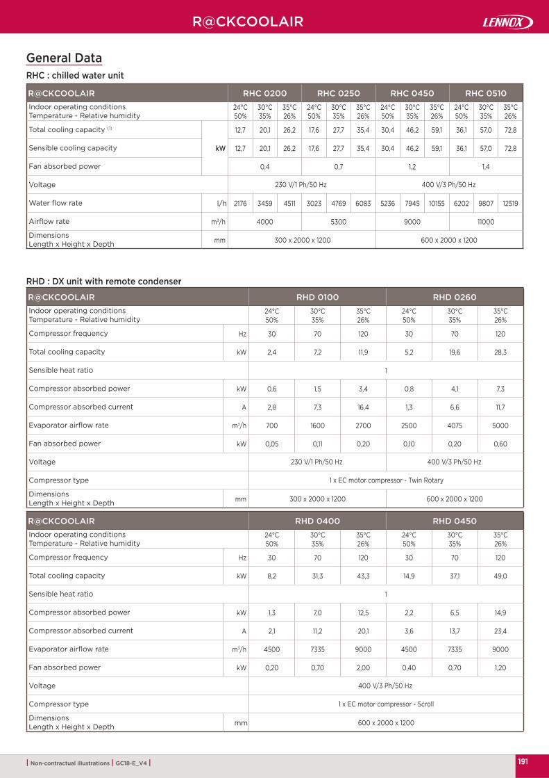
191
R@CKCOOLAIR RHC 0200 RHC 0250 RHC 0450 RHC 0510
24°C50%
30°C35%
35°C26%
24°C50%
30°C35%
35°C26%
24°C50%
30°C35%
35°C26%
24°C50%
30°C35%
35°C26%
kW
12,7 20,1 26,2 17,6 27,7 35,4 30,4 46,2 59,1 36,1 57,0 72,8
12,7 20,1 26,2 17,6 27,7 35,4 30,4 46,2 59,1 36,1 57,0 72,8
0,4 0,7 1,2 1,4
l/h 2176 3459 4511 3023 4769 6083 5236 7945 10155 6202 9807 12519
m3/h 4000 5300 9000 11000
mm 300 x 2000 x 1200 600 x 2000 x 1200
R@CKCOOLAIR RHD 0100 RHD 0260
24°C50%
30°C35%
35°C26%
24°C50%
30°C35%
35°C26%
Hz 30 70 120 30 70 120
kW 2,4 7,2 11,9 5,2 19,6 28,3
1
kW 0,6 1,5 3,4 0,8 4,1 7,3
A 2,8 7,3 16,4 1,3 6,6 11,7
m3/h 700 1600 2700 2500 4075 5000
kW 0,05 0,11 0,20 0,10 0,20 0,60
mm 300 x 2000 x 1200 600 x 2000 x 1200
R@CKCOOLAIR RHD 0400 RHD 0450
24°C50%
30°C35%
35°C26%
24°C50%
30°C35%
35°C26%
Hz 30 70 120 30 70 120
kW 8,2 31,3 43,3 14,9 37,1 49,0
1
kW 1,3 7,0 12,5 2,2 6,5 14,9
A 2,1 11,2 20,1 3,6 13,7 23,4
m3/h 4500 7335 9000 4500 7335 9000
kW 0,20 0,70 2,00 0,40 0,70 1,20
mm 600 x 2000 x 1200
R@CKCOOLAIR
| Non-contractual illustrations | GC18-E_V4 |
General DataRHC : chilled water unit
RHD : DX unit with remote condenser
Indoor operating conditionsTemperature - Relative humidity
Total cooling capacity (1)
Sensible cooling capacity
Fan absorbed power
Voltage 230 V/1 Ph/50 Hz 400 V/3 Ph/50 Hz
Water fl ow rate
Airfl ow rate
DimensionsLength x Height x Depth
Indoor operating conditionsTemperature - Relative humidity
Compressor frequency
Total cooling capacity
Sensible heat ratio
Compressor absorbed power
Compressor absorbed current
Evaporator airfl ow rate
Fan absorbed power
Voltage 230 V/1 Ph/50 Hz 400 V/3 Ph/50 Hz
Compressor type 1 x EC motor compressor - Twin Rotary
DimensionsLength x Height x Depth
Indoor operating conditionsTemperature - Relative humidity
Compressor frequency
Total cooling capacity
Sensible heat ratio
Compressor absorbed power
Compressor absorbed current
Evaporator airfl ow rate
Fan absorbed power
Voltage 400 V/3 Ph/50 Hz
Compressor type 1 x EC motor compressor - Scroll
DimensionsLength x Height x Depth

192
R@CKCOOLAIR
R@CKCOOLAIR RHV 0140 RHV 0240 RHV 0330
Hz 30 70 120 30 70 120 30 70 120
kW 4.1 10.2 13.3 5.8 19.4 24.8 8.5 26.8 34.6
1 1 1 1 1 1 1 0,91 0,89
m3/h 1550 2527 3100 2650 4328 5300 2650 4320 5300
kW 0.1 0.2 0.3 0.1 0.5 0.8 0.1 0.5 0.8
mm 300 x 2000 x 1200
Hz 30 70 120 30 70 120 30 70 120
kW 0.5 1.7 2.9 0.8 4.0 6.9 1.2 6.2 10.3
A 2.5 8.3 14.0 1.2 6.4 11.1 2.0 9.9 16.6
m3/h 6950 9300 16300
dB(A)61 63 63
46 46 49
mm 1250 x 560 x 1220 1300 x 600 x 1565 1890 x 1300 x 950
kg 100 332 492
| Non-contractual illustrations | GC18-E_V4 |
RHV : DX unit with remote motor-condensing unit
Indoor unit
Compressor frequency
Total cooling capacity
Sensible heat ratio
Evaporator airfl ow rate
Fan absorbed power
Voltage 230 V/1 Ph/50 Hz
DimensionsLength x Height x Depth
Outdoor unit
Compressor frequency
Compressor absorbed power
Compressor absorbed current
Compressor type BLDCTwin rotary
BLDCScroll
Condenser airfl ow rate
Soud power level
Sound pressure level (10 m free fi eld)
Voltage 230 V/1 Ph/50 Hz 400 V/3 Ph/50 Hz
DimensionsLength x Height x Depth
Weight

193
|
ADALINK II 194
|
LennoxVision 195
|
LennoxOneWeb 195
|
LennoxCloud 196
|
LennoxHydroControl 197
| Non-contractual illustrations | GC18-E_V4 |
Controls & BMS
Lennox web serverOne site - Several units
Lennox BMSOne site - Multi protocol
LENNOX web serverOne site - Only one unit
Lennox web portalMulti sites - Multi units
Lennox HVAC hydronic systemFan coils and chillers control

194
*
*
ADALINK II
| Non-contractual illustrations | GC18-E_V4 |
Logo and background may be easily customized (FTP)
Logo and background may be easily customized (FTP)
*
Direct connection on PC,using any internet browser
Distant customer,using internet browser
Digital Tablet/Phone
Main applications• BMS “light” system• Small installations: up to 16 LENNOX units
Lennox web serverOne site - Several units
DESCRIPTION :
Lennox solution for HVAC installation monitoring. It can be connected to diff erent LENNOX units
As an option, possibilty to integrate other communication devices (energy meters, boilers, lighting...)
ADALINK II allows an overview of the whole site map showing the status of the diff erent units, zooming on each unit and allowing the user to graphically change the set-point, the access to the alarm list, and giving the access to the trend curves
Ideal tool for both genuine users giving access only to specifi c set-points of the unit, or maintenance specialists (expert mode) giving access to all the parameters of the unit
Easy scheduling and zoning management CLIMATIC 50, CLIMATIC 60 and eCLIMATIC
compatible Unloading function (50% and 100% of capacity) Compatible with one CLIMATIC 60 Chiller Very easy to install, it can be used on any computer
through Internet navigator locally and remotely via IP network
I/O are available for counter and energy meter Option Modbus table is available for specifi c device
(Chiller, AHU, energy meter…) Export trends with report alarm by email
ADALINK CHILLERLennox web server1 Site - Several liquid chillers
ADALINK can monitor up to 8 CL50 and CL60 units, with same functionalities as ADALINK II.
D
A
* Logo and background may be easily customized (FTP)
*

195
LennoxVision LennoxOneWeb
| Non-contractual illustrations | GC18-E_V4 |
Main applications• Real and full BMS system• Large installations: unlimited number of units
Lennox BMSOne site - Multi protocol
Lennox web server 1 Site - Only one unit
DESCRIPTION :
Lennox supervision and remote maintenance system
. Can be connected to any compatible Lennox unit and external components
. Real BMS system allowing access to the variables of all the units and carrying out monitoring, scheduling and energy management
Full management of the diff erent units on the site : unit, service, alarm, curves and scheduling screens
. Including remote connection via an internet connection (options), communication with other BMS, management of alert messages by SMS or email and lighting management
LennoxVision can be used as a local system, or as a monitoring system with access from a remote workstation via an internet connection
LennoxVision includes a complete pre-confi gured version of software running on dedicated hardware, and features all the communication ports required to best exploit its Web Server and installation supervision functions
DESCRIPTION :
Web page (animated gif) Time scheduler (weekly basis) Parameters access Software upgrade Alarm alerts (mailing) Trends Ethernet connexion
D
D

196
LennoxCloud
| Non-contractual illustrations | GC18-E_V4 |
DESCRIPTION :
LennoxCloud remotely tracks the units operation on the customer site.
Through LennoxCloud, the unit can be remotely controlled, adjusted, or diagnosed by our experts.
LennoxCloud can check (live data trends), optimize (store data analysis) and troubleshoot (alarm/alert reports) customer units.
LennoxCloud allows signifi cant energy savings optimizing performances during all the unit’s life cycle.
ADVANCED DIAGNOSTIC & PROGNOSTIC OPTION :
In order to optimize the installation, both increasing the unit performance and decreasing the energy consumption, LennoxCloud solution can be enhanced through the advanced diagnostic & prognostic option.
Through this option, Lennox experts can analyze and follow your installation, improving the performance of your HVAC system, raising appropriate scenari for maintenance and energy savings. It can also provide you periodical reports and diagnostics. In addition to data storage, several options allow optimization of your data management by improving the use of your HVAC system
. Data processing and analysis . Optimized HVAC engineering scenari . Monthly report to customer . Savings’ follow-up (on a money point of view) . 24h/24h alarm alerts . Remote Assistance
D
A&
Smartphones & tablets applications
Owner website
Customer services portal
Alarm manager
LENNOX Rooftops & Chillers
Main applications• Cloud storage• Remote monitoring
Lennox web portalMulti sites - Multi units

197
LennoxHydroControl
| Non-contractual illustrations | GC18-E_V4 |
LennoxHydroControl available for all hydronic installations
Chillers & heat-pumps
Air handling units
Fancoil units
Main applications• Fan coils and chillers control• Small and medium-size applications for offi ces
Lennox HVAC hydronic systemFan coils and chillers control
DESCRIPTION :
Smartest solution for hydronic systems: . Manages and coordinates cooling and heating
production (chiller/heat-pump units) through fancoils
. Ensures customer comfort, providing important energy savings through building zoning, time scheduling and set points
Available for all hydronic installations (cooling only, heating only, reversible system).
Optimized for small and medium size applications. LennoxHydroControl manages up to 8 zones for
fancoils and one for chiller/heatpump.
Managed locally, through simplifi ed local color touch screen interface (HMI), or remotely by internet browser thanks to the Web-Server embedded in the HMI.
Based on a shared communication system among Lennox devices, which ensures full compatibility, best performances and easy commissioning and maintenance.
High performances and high energy savings compared to traditional cooling/heating systems.
Lennox fancoils are equipped with EC fan motors, allowing to match perfectly the airfl ow rate to the customer comfort requirement.
D
www.lennoxemea.com
GC18-E_V4
Due to LENNOX EMEA ongoing commitment to quality, the specifi cations, ratings and dimensions are subject to change without notice and without incurring liability.Improper installation, adjustment, alteration, service or maintenance can cause property damage or personal injury.Installation and service must be performed by a qualifi ed installer and servicing agency.