GENERAL CATALOGUE - Vergnano Tools
262
GENERAL CATALOGUE taps - dies thread mills - tapping attachments # 75 EN
-
Upload
khangminh22 -
Category
Documents
-
view
2 -
download
0
Transcript of GENERAL CATALOGUE - Vergnano Tools

I N D E XTOOL CODE LIST
A SERIES
TOOL CODE Thread Page
A1 M 34A1 LH M 36A2 MF 79A2 LH MF 82A4 BSW 131A5 G 121A6 Rc (BSPT) 130A6 B NPT 134A6 BZ NPT 135A6 F NPTF 136A6 FZ NPTF 137A7 UNC 103A8 UNF 111A9 M 73A10 MF 98A15 AZ M 52A15 AZ TiH1 M 52A15 L M 53A15 L TiN M 53A15 S M 45A15 S VAP M 45A15 S TiN M 45A15 S TiCN M 45A15 S 4H M 47A15 S 4H TiN M 47A15 S 6G M 48A15 S 6G TiN M 48A15 S 7G M 49A15 S 7G TiN M 49A15 S LH M 50A15 S LH TiN M 50A16 S M 51A16 S TiN M 51A17 S MF 87A17 S VAP MF 87A17 S TiN MF 87A17 S TiCN MF 87A17 S TiX2 MF 90A17 S 6G MF 91A17 S 6G TiN MF 91A18 S G 124A18 S VAP G 124A18 S TiCN G 124A18 S TiX2 G 124A19 S UNC 106A19 S TiN UNC 106A19 S TiCN UNC 106A19 S 3B UNC 106A19 S TiX2 UNC 107A20 S UNF 114A20 S TiN UNF 114A20 S TiCN UNF 114A20 S 3B UNF 114A20 S TiX2 UNF 115A21 FC M 38A21 FC TiN M 38A22 FC M 40A22 FC TiN M 40A23 FC MF 83A23 FC TiN MF 83A23 FC LH MF 83A24 FC BSW 132A24 FP BSW 132A26 FC G 122A26 FP G 122A27 FC UNC 104A27 FC TiN UNC 104A27 FP UNC 104A27 FP TiN UNC 104A28 FC UNF 112A28 FC TiN UNF 112A28 FP UNF 112A28 FP TiN UNF 112A29 M 55A29 VAP M 55A29 TiN M 55A29 6G M 57
A SERIES
TOOL CODE Thread Page
A29 6G TiN M 57A29 DIN 376 M 58A29 DIN 376 TiN M 58A29 L M 59A29 L TiN M 59A30 MF 92A30 TiN MF 92A31 BSW 133A31 TiN BSW 133A32 G 125A32 TiN G 125A33 UNC 108A33 TiN UNC 108A33 3B UNC 108A34 UNF 116A34 TiN UNF 116A34 3B UNF 116A43 NITR. M 41A43 TiCN M 41A44 NITR. M 42A44 TiCN M 42A45 NITR. MF 86A45 TiCN MF 86A48 NITR. G 123A48 TiCN G 123A49 NITR. UNC 105A49 TiCN UNC 105A50 NITR. UNF 113A50 TiCN UNF 113A59 S G 126A59 S VAP G 126A59 S TiN G 126A59 S TiCN G 126A59 S TiX2 G 127A60 S UNC 109A60 S TiN UNC 109A60 S TiCN UNC 109A60 S TiX2 UNC 109A61 S UNF 117A61 S TiN UNF 117A61 S TiCN UNF 117A61 S TiX2 UNF 117A62 M 71A62 TiH1 M 71A65 UNC 110A66 UNF 118A67 M 43A67 TiH1 M 43A70 L M 68A70 L TiN M 68A70 S M 60A70 S VAP M 60A70 S TiN M 60A70 S TiCN M 60A70 S 4H M 61A70 S 4H TiN M 61A70 S 6G M 62A70 S 6G TiN M 62A70 S 7G M 63A70 S 7G TiN M 63A70 SE M 65A70 SE TiN M 65A70 S LH M 66A70 S LH TiN M 66A71 S MF 95A71 S VAP MF 95A71 S TiN MF 95A71 S TiCN MF 95A71 S TiX2 MF 96A71 S 6G MF 97A71 S 6G TiN MF 97A72 M 72A72 TiH1 M 72A76 S M 67A76 S TiN M 67A80 TiN M 74A80 TiCN M 74
A SERIES
TOOL CODE Thread Page
A80 6GX TiN M 75A80 6GX TiCN M 75A80 N TiN M 76A80 N TiCN M 76A80 N 6GX TiN M 77A80 N 6GX TiCN M 77A81 TiN MF 99A81 TiCN MF 99A81 6GX TiN MF 100A81 6GX TiCN MF 100A81 N TiN MF 101A81 N TiCN MF 101A81 N 6GX TiN MF 102A81 N 6GX TiCN MF 102A82 N TiN G 128A82 N TiCN G 128A100 M 37A110 VAP M 44A110 CrN M 44A119 8-UN 119A119 TiN 8-UN 119A120 M 69A120 VAP M 69A120 TiN M 69A150 VAP M 54A150 TiX2 M 54A159 S Rp (BSPP) 129A159 S TiN Rp (BSPP) 129A160 8-UN 120A160 TiN 8-UN 120A170 VAP M 70A170 TiX2 M 70A190 EG-M 78A701 S M 64A701 S TiN M 64
F.LLI VERGNANO S.r.l. Corso Egidio Olia, 210023 Chieri - TO - ItalyTe l . +39 0119423523Fax . +39 0119425426i n f o @ v e r g n a n o . c o m
# 75
EN
G E N E R A L C A T A L O G U Et a p s - d i e s
t h r e a d m i l l s - t a p p i n g a t t a c h m e n t s
# 75 EN
INTRODUCTION
New Products Catalogue n° 75 6
Guide to Tap Application Table 8
Guide to Tap Datasheets 9
Guide to Thread Mills Datasheets 10
Guide to Tapping Attachments Datasheets 11
Guide to TappFinder App 12
Tap Application Table 14
“A” SERIES - TAPS FOR GENERIC APPLICATIONS
M ISO Metric coarse thread - DIN 13 34
EG-M ISO Metric coarse thread (for wire inserts) - DIN 8140-2 78
MF ISO Metric fine thread - DIN 13 79
UNC Unified coarse thread - ASME B1.1 103
UNF Unified fine thread - ASME B1.1 111
8-UN Unified constant pitch series thread - ASME B1.1 119
G Gas Whitworth thread - EN ISO 228 121
Rp Rp thread (BSPP) - DIN EN 10226-1 129
Rc Conical gas thread (BSPT), taper 1:16 - BS 21 and DIN EN 10226-2 130
BSW Whitworth thread - BS 84 131
NPT National pipe thread, taper 1:16 - ASME/ANSI B1.20.1 134
NPTF Dryseal National pipe thread, taper 1:16 - ASME/ANSI B1.20.3 136
“P” SERIES - HIGH PERFORMANCE TAPS
M ISO Metric coarse thread - DIN 13 140
MF ISO Metric fine thread - DIN 13 157
G Gas Whitworth thread - EN ISO 228 164
“S” SERIES - SYNCHRONOUS TAPS
M ISO Metric coarse thread - DIN 13 168
MF ISO Metric fine thread - DIN 13 172
“H” SERIES - SOLID CARBIDE TAPS
M ISO Metric coarse thread - DIN 13 176
MF ISO Metric fine thread - DIN 13 180
“F” DIES
M ISO Metric coarse thread - DIN 13 204
MF ISO Metric fine thread - DIN 13 205
UNC Unified coarse thread - ASME B1.1 208
UNF Unified fine thread - ASME B1.1 209
G Gas Whitworth thread - EN ISO 228 210
BSW Whitworth thread - BS 84 211
NPT National pipe thread, taper 1:16 - ASME/ANSI B1.20.1 212
DISCONTINUED TAPS 184
THREAD MILLS
ISO Thread milles carbide 217
UN Thread milles carbide 220
GAS Thread milles carbide 223
SYNCHRONOUS TAPPING ATTACHMENTS
Synchronous Tapping Attachments 228
Accessories 232
TECHNICAL INFORMATION 238

TOOL CODE LIST
VA SERIES
TOOL CODE Page
DIN 69893 HSK A 228DIN 1835 B+E 228SK DIN 69871 AD 229SK DIN 69871 AD+B 229MAS 403 BT 230MAS 403 BT - B 230ISO 26623-1 231Quick-Change Tap Adaptor 232Extended Quick-Change Tap Adaptor 232ER Collet 233Assembly Support 234Wrench 234
P SERIES
TOOL CODE Thread Page
P15 TiN M 143P15 TiH1 M 143P15 6GX TiH1 M 143BP15 TiH1 M 143P17 TiN MF 158P17 TiH1 MF 158P17 6GX TiH1 MF 158BP17 TiH1 MF 158P18 TiN G 164P18 TiH1 G 164P29 M 144P29 TiN M 144P29 TiH1 M 144BP29 TiH1 M 144P29 E TiH1 M 145P30 MF 159P30 TiN MF 159P30 TiH1 MF 159BP30 TiH1 MF 159P43 V-MAXX M 140BP43 V-MAXX M 140P43 E V-MAXX M 141BP43 E V-MAXX M 141P45 V-MAXX MF 157BP45 V-MAXX MF 157P45 E V-MAXX MF 157BP45 E V-MAXX MF 157P59 TiN G 165P59 TiH1 G 165P59 E TiH1 G 165P70 TiN M 146P70 TiH1 M 146BP70 TiH1 M 147P70 6GX TiH1 M 146P70 7GX TiH1 M 146P70 E TiN M 148P70 E TiH1 M 148P70 E 6GX TiH1 M 148P71 TiN MF 160P71 TiH1 MF 160P71 6GX TiH1 MF 160BP71 TiH1 MF 160P71 E TiH1 MF 161P76 L TiH1 M 149P80 TiN M 150P80 V-MAXX M 150P80 6GX TiN M 150P80 7GX TiN M 150P80 N TiN M 151P80 N V-MAXX M 151P80 N 6GX TiN M 151P80 N 7GX TiN M 151P80 E TiN M 152P80 N E TiN M 152P80 N E V-MAXX M 152P80 N E 6GX TiN M 152P80 N L TiN M 155P80 N LH TiN M 154BP80 N TiN M 153BP80 N R TiN M 153BP80 N R V-MAXX M 153BP80 N E V-MAXX M 153P81 TiN MF 162P81 V-MAXX MF 162P81 6GX TiN MF 162P81 N TiN MF 163P81 N V-MAXX MF 163P81 N 6GX TiN MF 163P82 N TiN G 166P82 N V-MAXX G 166P130 M 142P130 V-MAXX M 142P180 N TiN M 156P180 N V-MAXX M 156
S SERIES
TOOL CODE Thread Page
S15 TiN M 169S15 TiH1 M 169BS15 TiH1 M 169S17 TiN MF 173S43 V-MAXX M 168BS43 V-MAXX M 168S43 E V-MAXX M 168BS43 E V-MAXX M 168S45 V-MAXX MF 172BS45 V-MAXX MF 172S70 TiN M 170S70 TiH1 M 170BS70 TiH1 M 170S71 TiN MF 174S80 N TiN M 171S80 N V-MAXX M 171S80 N 6GX TiN M 171BS80 N R TiN M 171
VR SERIES
TOOL CODE Thread Page
VR10 TiAlN ISO 217VR20 TiAlN ISO 217VR30 TiAlN ISO 217VR40 TiAlN ISO 218VR45 TiAlN ISO 218VR50 TiAlN ISO 219VR55 TiAlN ISO 219VR10 TiAlN UN 220VR20 TiAlN UN 220VR40 TiAlN UN 221VR45 TiAlN UN 221VR50 TiAlN UN 222VR55 TiAlN UN 222VR10 TiAlN G 223VR20 TiAlN G 223
H SERIES
TOOL CODE Thread Page
HB29 M 177HB29 V-MAXX M 177HB43 M 176HB43 V-MAXX M 176HB43 E V-MAXX M 176HB45 MF 180HB45 V-MAXX MF 180HB45 E V-MAXX MF 180HB80 N R V-MAXX M 179HB81 N R E V-MAXX M 181H130 M 178H130 V-MAXX M 178
F SERIES
TOOL CODE Thread Page
X200 M 204X200 LH M 204X201 MF 205X202 BSW 211X203 G 210X204 UNC 208X205 UNF 209X206 NPT 212
Changes or printing errors regarding technical details do not justify any claims.We reserve the right to introduce changes regarding technical details, without prior notice.
Complete or partial reproduction of this catalogue is not permitted without our prior permission.
ISO 513 Material Group Application R. N/mm2 Lubrication
P Steel
P.1 Mild / magnetic steel 200 - 400 E, O, MQL
P.2 Construction steel, case hardening steel 350 - 700 E, O, MQL
P.3 Carbon steel 350 - 850 E, O, MQL
P.4 Alloyed steel / tempered steel 500 - 850 E, O, MQL
P.5 Alloyed steel / tempered steel 850 - 1200 E, O, MQL
P.6 Alloyed steel / high strength steel 1200 - 1600 O
P.7 Ferritic stainless steel, martensitic stainless steel, precipitation hardening < 1000 E, O, MQL
M Stainless steelM.1 Austenitic stainless steel < 850 E, O, MQL
M.2 Ferritic+austenitic (Duplex) < 1000 O, MQL
K Cast iron
K.1 Grey cast iron < 1000 E, O, MQL
K.2 Nodular cast iron, malleable cast iron, tempered cast iron < 1000 E, O, MQL
K.3 Austempered ductile iron (ADI) < 1400 O, MQL
N
AluminiumAluminium
alloys
N.1 Pure aluminium < 300 E, O, MQL
N.2 Aluminium wrought and die cast alloys with Si < 0,5% (long chipping) < 500 E, O, MQL
N.3 Aluminium wrought and die cast alloys with Si < 10% (medium chipping) < 500 E, O, MQL
N.4 Aluminium die cast alloys with Si > 10% (short chipping) < 600 E, O, MQL
CopperCopper alloys
BrassBronze
N.5 Pure copper 250 - 350 E, O, MQL
N.6 Copper alloys (long chipping), soft brass < 700 E, O, MQL
N.7 Copper alloys (short chipping), hard brass < 700 E, O, MQL
N.8 High strength bronze 700 - 1500 O
MagnesiumMagnesium alloys
N.9 Pure magnesium, magnesium alloys 120 - 300 E, O, MQL
N.10 High strength magnesium alloys 240 - 400 E, O, MQL
S
TitaniumTitanium alloys
S.1 Pure titanium 400 - 600 E, O, MQL
S.2 Titanium alloys 600 - 1000 O, MQL
NickelNickel alloys
S.3 Pure nickel 400 - 600 E, O, MQL
S.4 Nickel alloys 600 - 1000 O, MQL
H Hardenedmaterials
H.1 Alloyed steel, hardness HRC 44-55 - O
H.2 Alloyed steel, hardness HRC 56-63 - O
SERIES
MATERIAL
CHAMFER FORM
TYPE OF HOLE
COATING
LUBRICATION
See pages 14 ÷ 32 >
*For specific material examples see “Technical Information” section on page 248
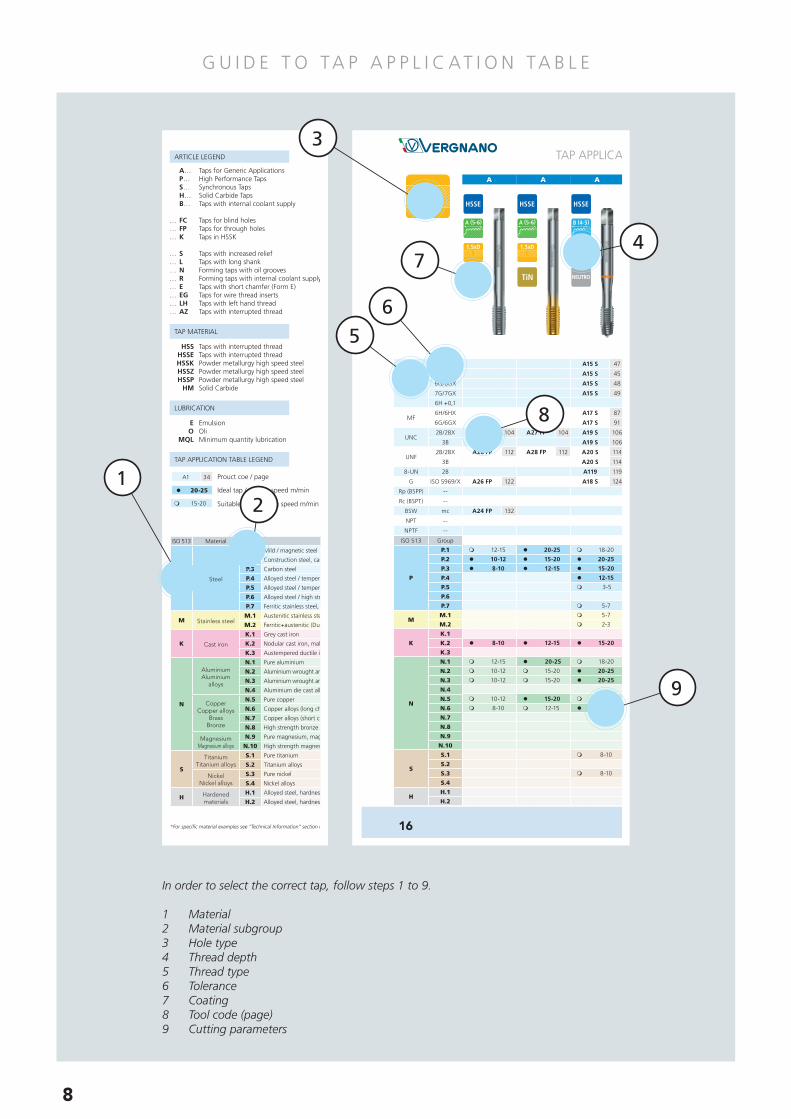
A… Taps for Generic Applications P… High Performance Taps S… Synchronous Taps H… Solid Carbide Taps B… Taps with internal coolant supply
… FC Taps for blind holes… FP Taps for through holes
… S Taps with increased relief… L Taps with long shank… N Forming taps with oil grooves… R Forming taps with internal coolant supply and radial outlet… E Taps with short chamfer (Form E)… EG Taps for wire thread inserts… LH Taps with left hand thread… AZ Taps with interrupted thread
ARTICLE LEGEND
TAP MATERIAL
LUBRICATION
TAP APPLICATION TABLE LEGEND
E Emulsion O Oil MQL Minimum quantity lubrication
HSS Conventional high speed steel HSSE Conventional high speed steel HSSK Powder metallurgy high speed steel HSSZ Powder metallurgy high speed steel HSSP Powder metallurgy high speed steel HM Solid Carbide
m 15-20
l 20-25
A1 34 Product code / page
Ideal tap / cutting speed m/min
Suitable tap / cutting speed m/min
M
4H
6H/6HX
6G/6GX
7G/7GX
6H +0,1
MF6H/6HX
6G/6GX
UNC2B/2BX
3B
UNF2B/2BX
3B
8-UN 2B
G ISO 5969/X
Rp (BSPP) --
Rc (BSPT) --
BSW mc
NPT --
NPTF --

TOOL CODE LIST
VA SERIES
TOOL CODE Page
DIN 69893 HSK A 228DIN 1835 B+E 228SK DIN 69871 AD 229SK DIN 69871 AD+B 229MAS 403 BT 230MAS 403 BT - B 230ISO 26623-1 231Quick-Change Tap Adaptor 232Extended Quick-Change Tap Adaptor 232ER Collet 233Assembly Support 234Wrench 234
P SERIES
TOOL CODE Thread Page
P15 TiN M 143P15 TiH1 M 143P15 6GX TiH1 M 143BP15 TiH1 M 143P17 TiN MF 158P17 TiH1 MF 158P17 6GX TiH1 MF 158BP17 TiH1 MF 158P18 TiN G 164P18 TiH1 G 164P29 M 144P29 TiN M 144P29 TiH1 M 144BP29 TiH1 M 144P29 E TiH1 M 145P30 MF 159P30 TiN MF 159P30 TiH1 MF 159BP30 TiH1 MF 159P43 V-MAXX M 140BP43 V-MAXX M 140P43 E V-MAXX M 141BP43 E V-MAXX M 141P45 V-MAXX MF 157BP45 V-MAXX MF 157P45 E V-MAXX MF 157BP45 E V-MAXX MF 157P59 TiN G 165P59 TiH1 G 165P59 E TiH1 G 165P70 TiN M 146P70 TiH1 M 146BP70 TiH1 M 147P70 6GX TiH1 M 146P70 7GX TiH1 M 146P70 E TiN M 148P70 E TiH1 M 148P70 E 6GX TiH1 M 148P71 TiN MF 160P71 TiH1 MF 160P71 6GX TiH1 MF 160BP71 TiH1 MF 160P71 E TiH1 MF 161P76 L TiH1 M 149P80 TiN M 150P80 V-MAXX M 150P80 6GX TiN M 150P80 7GX TiN M 150P80 N TiN M 151P80 N V-MAXX M 151P80 N 6GX TiN M 151P80 N 7GX TiN M 151P80 E TiN M 152P80 N E TiN M 152P80 N E V-MAXX M 152P80 N E 6GX TiN M 152P80 N L TiN M 155P80 N LH TiN M 154BP80 N TiN M 153BP80 N R TiN M 153BP80 N R V-MAXX M 153BP80 N E V-MAXX M 153P81 TiN MF 162P81 V-MAXX MF 162P81 6GX TiN MF 162P81 N TiN MF 163P81 N V-MAXX MF 163P81 N 6GX TiN MF 163P82 N TiN G 166P82 N V-MAXX G 166P130 M 142P130 V-MAXX M 142P180 N TiN M 156P180 N V-MAXX M 156
S SERIES
TOOL CODE Thread Page
S15 TiN M 169S15 TiH1 M 169BS15 TiH1 M 169S17 TiN MF 173S43 V-MAXX M 168BS43 V-MAXX M 168S43 E V-MAXX M 168BS43 E V-MAXX M 168S45 V-MAXX MF 172BS45 V-MAXX MF 172S70 TiN M 170S70 TiH1 M 170BS70 TiH1 M 170S71 TiN MF 174S80 N TiN M 171S80 N V-MAXX M 171S80 N 6GX TiN M 171BS80 N R TiN M 171
VR SERIES
TOOL CODE Thread Page
VR10 TiAlN ISO 217VR20 TiAlN ISO 217VR30 TiAlN ISO 217VR40 TiAlN ISO 218VR45 TiAlN ISO 218VR50 TiAlN ISO 219VR55 TiAlN ISO 219VR10 TiAlN UN 220VR20 TiAlN UN 220VR40 TiAlN UN 221VR45 TiAlN UN 221VR50 TiAlN UN 222VR55 TiAlN UN 222VR10 TiAlN G 223VR20 TiAlN G 223
H SERIES
TOOL CODE Thread Page
HB29 M 177HB29 V-MAXX M 177HB43 M 176HB43 V-MAXX M 176HB43 E V-MAXX M 176HB45 MF 180HB45 V-MAXX MF 180HB45 E V-MAXX MF 180HB80 N R V-MAXX M 179HB81 N R E V-MAXX M 181H130 M 178H130 V-MAXX M 178
F SERIES
TOOL CODE Thread Page
X200 M 204X200 LH M 204X201 MF 205X202 BSW 211X203 G 210X204 UNC 208X205 UNF 209X206 NPT 212
Changes or printing errors regarding technical details do not justify any claims.We reserve the right to introduce changes regarding technical details, without prior notice.
Complete or partial reproduction of this catalogue is not permitted without our prior permission.
ISO 513 Material Group Application R. N/mm2 Lubrication
P Steel
P.1 Mild / magnetic steel 200 - 400 E, O, MQL
P.2 Construction steel, case hardening steel 350 - 700 E, O, MQL
P.3 Carbon steel 350 - 850 E, O, MQL
P.4 Alloyed steel / tempered steel 500 - 850 E, O, MQL
P.5 Alloyed steel / tempered steel 850 - 1200 E, O, MQL
P.6 Alloyed steel / high strength steel 1200 - 1600 O
P.7 Ferritic stainless steel, martensitic stainless steel, precipitation hardening < 1000 E, O, MQL
M Stainless steelM.1 Austenitic stainless steel < 850 E, O, MQL
M.2 Ferritic+austenitic (Duplex) < 1000 O, MQL
K Cast iron
K.1 Grey cast iron < 1000 E, O, MQL
K.2 Nodular cast iron, malleable cast iron, tempered cast iron < 1000 E, O, MQL
K.3 Austempered ductile iron (ADI) < 1400 O, MQL
N
AluminiumAluminium
alloys
N.1 Pure aluminium < 300 E, O, MQL
N.2 Aluminium wrought and die cast alloys with Si < 0,5% (long chipping) < 500 E, O, MQL
N.3 Aluminium wrought and die cast alloys with Si < 10% (medium chipping) < 500 E, O, MQL
N.4 Aluminium die cast alloys with Si > 10% (short chipping) < 600 E, O, MQL
CopperCopper alloys
BrassBronze
N.5 Pure copper 250 - 350 E, O, MQL
N.6 Copper alloys (long chipping), soft brass < 700 E, O, MQL
N.7 Copper alloys (short chipping), hard brass < 700 E, O, MQL
N.8 High strength bronze 700 - 1500 O
MagnesiumMagnesium alloys
N.9 Pure magnesium, magnesium alloys 120 - 300 E, O, MQL
N.10 High strength magnesium alloys 240 - 400 E, O, MQL
S
TitaniumTitanium alloys
S.1 Pure titanium 400 - 600 E, O, MQL
S.2 Titanium alloys 600 - 1000 O, MQL
NickelNickel alloys
S.3 Pure nickel 400 - 600 E, O, MQL
S.4 Nickel alloys 600 - 1000 O, MQL
H Hardenedmaterials
H.1 Alloyed steel, hardness HRC 44-55 - O
H.2 Alloyed steel, hardness HRC 56-63 - O
SERIES
MATERIAL
CHAMFER FORM
TYPE OF HOLE
COATING
LUBRICATION
See pages 14 ÷ 32 >
*For specific material examples see “Technical Information” section on page 248
A… Taps for Generic Applications P… High Performance Taps S… Synchronous Taps H… Solid Carbide Taps B… Taps with internal coolant supply
… FC Taps for blind holes… FP Taps for through holes
… S Taps with increased relief… L Taps with long shank… N Forming taps with oil grooves… R Forming taps with internal coolant supply and radial outlet… E Taps with short chamfer (Form E)… EG Taps for wire thread inserts… LH Taps with left hand thread… AZ Taps with interrupted thread
ARTICLE LEGEND
TAP MATERIAL
LUBRICATION
TAP APPLICATION TABLE LEGEND
E Emulsion O Oil MQL Minimum quantity lubrication
HSS Conventional high speed steel HSSE Conventional high speed steel HSSK Powder metallurgy high speed steel HSSZ Powder metallurgy high speed steel HSSP Powder metallurgy high speed steel HM Solid Carbide
m 15-20
l 20-25
A1 34 Product code / page
Ideal tap / cutting speed m/min
Suitable tap / cutting speed m/min
M
4H
6H/6HX
6G/6GX
7G/7GX
6H +0,1
MF6H/6HX
6G/6GX
UNC2B/2BX
3B
UNF2B/2BX
3B
8-UN 2B
G ISO 5969/X
Rp (BSPP) --
Rc (BSPT) --
BSW mc
NPT --
NPTF --

General Catalogue n° 75 - EN

1944Company foundation.Production of end mills
1949Production of taps
commences
1960Enlargement of
Corso Torino plant
1980Production reaches 1 million
taps per year
2016New of�ce of German subsidiary
opens in Achern 201975th Anniversary ofcompany foundation
1950Construction and transfer to new
production plant in Corso Torino, Chieri
1992German subsidiary opens,
Vergnano GmbH
2008South Korean subsidiary opens,
Vergnano Korea
2002Transfer to newly built production
plant in Corso Olia, Chieri
V E R G N A N O 19 4 4 - 2 0 19
With over 75 years of experience in the cutting tool industry, Vergnano is one of the world’s leading
manufacturers of high quality precision threading taps, hobs, end mills and threading dies.
While keeping a firm foothold in the honoured tradition of the Vergnano brand, Vergnano has established
itself internationally and is renowned for quality, reliability, flexibility, innovation and commitment.
4

1944Company foundation.Production of end mills
1949Production of taps
commences
1960Enlargement of
Corso Torino plant
1980Production reaches 1 million
taps per year
2016New of�ce of German subsidiary
opens in Achern 201975th Anniversary ofcompany foundation
1950Construction and transfer to new
production plant in Corso Torino, Chieri
1992German subsidiary opens,
Vergnano GmbH
2008South Korean subsidiary opens,
Vergnano Korea
2002Transfer to newly built production
plant in Corso Olia, Chieri
5

N E W P R O D U C T S 2 0 19
P29ENew P29 version with chamfer
form E for blind holes
MDIN 13
P
SERIES
P SK N
P70 7GX TiH1New P70 version with
tolerance 7GX for blind holes
MDIN 13
P
SERIES
P76L TiH1Long P70 version with long
through shank for blind holes
MDIN 13
P
SERIES
P80N LH TiNNew high performance forming
taps for lefthand threads
P M SN
MDIN 13
P
SERIES
6
P SK NM
P SK NM

P80N L TiNNew high performance forming
taps with long shank
P M SN
MDIN 13
P
SERIES
K N
HB43E V-MAXXNew HB43 version with
chamfer form E for blind holes
MDIN 13
H
SERIES
K N
HB45E V-MAXXNew HB45 version with
chamfer form E for blind holes
MFDIN 13
H
SERIES
P M SN
HB81NRE V-MAXXNew solid carbide forming taps
with chamfer form E and internal
radial coolant
MFDIN 13
H
SERIES
7
G U I D E T O TA P A P P L I C AT I O N TA B L E
TOOL CODE LIST
VA SERIES
TOOL CODE Page
DIN 69893 HSK A 228DIN 1835 B+E 228SK DIN 69871 AD 229SK DIN 69871 AD+B 229MAS 403 BT 230MAS 403 BT - B 230ISO 26623-1 231Quick-Change Tap Adaptor 232Extended Quick-Change Tap Adaptor 232ER Collet 233Assembly Support 234Wrench 234
P SERIES
TOOL CODE Thread Page
P15 TiN M 143P15 TiH1 M 143P15 6GX TiN M 143BP15 TiH1 M 143P17 TiN MF 158P17 TiH1 MF 158P17 6GX TiN MF 158BP17 TiH1 MF 158P18 TiN G 164P18 TiH1 G 164P29 M 144P29 TiN M 144P29 TiH1 M 144BP29 TiH1 M 144P29 E TiH1 M 145P30 MF 159P30 TiN MF 159P30 TiH1 MF 159BP30 TiH1 MF 159P43 V-MAXX M 140BP43 V-MAXX M 140P43 E V-MAXX M 141BP43 E V-MAXX M 141P45 V-MAXX MF 157BP45 V-MAXX MF 157P45 E V-MAXX MF 157BP45 E V-MAXX MF 157P70 TiN M 146P70 TiH1 M 146BP70 TiH1 M 147P70 6GX TiH1 M 146P70 7GX TiH1 M 146P70 E TiN M 148P70 E TiH1 M 148P70 E 6GX TiH1 M 148P71 TiN MF 160P71 TiH1 MF 160P71 6GX TiN MF 160BP71 TiH1 MF 160P71 E TiH1 MF 161P76 L TiH1 M 149P59 TiN G 165P59 TiH1 G 165P59 E TiH1 G 165P80 TiN M 150P80 V-MAXX M 150P80 6GX TiN M 150P80 7GX TiN M 150P80 N TiN M 151P80 N V-MAXX M 151P80 N 6GX TiN M 151P80 N 7GX TiN M 151P80 E TiN M 152P80 N E TiN M 152P80 N E V-MAXX M 152P80 N E 6GX TiN M 152P80 N L TiN M 155P80 N LH TiN M 154BP80 N TiN M 153BP80 NR TiN M 153BP80 NR V-MAXX M 153BP80 N E V-MAXX M 153P81 TiN MF 162P81 V-MAXX MF 162P81 6GX TiN MF 162P81 N TiN MF 163P81 N V-MAXX MF 163P81 N 6GX TiN MF 163P82 N TiN G 166P82 N V-MAXX G 166P130 M 142P130 V-MAXX M 142P180 N TiN M 156P180 N V-MAXX M 156
S SERIES
TOOL CODE Thread Page
S15 TiN M 169S15 TiH1 M 169BS15 TiH1 M 169S17 TiN MF 173S43 V-MAXX M 168BS43 V-MAXX M 168S43 E V-MAXX M 168BS43 E V-MAXX M 168S45 V-MAXX MF 172BS45 V-MAXX MF 172S70 TiN M 170S70 TiH1 M 170BS70 TiH1 M 170S71 TiN MF 174S80 N TiN M 171S80 N V-MAXX M 171S80 N 6GX TiN M 171BS80 NR TiN M 171
VR SERIES
TOOL CODE Thread Page
VR10 TiAlN ISO 217VR20 TiAlN ISO 217VR30 TiAlN ISO 217VR40 TiAlN ISO 218VR45 TiAlN ISO 218VR50 TiAlN ISO 219VR55 TiAlN ISO 219VR10 TiAlN UN 220VR20 TiAlN UN 220VR40 TiAlN UN 221VR45 TiAlN UN 221VR50 TiAlN UN 222VR55 TiAlN UN 222VR10 TiAlN G 223VR20 TiAlN G 223
H SERIES
TOOL CODE Thread Page
HB29 M 177HB29 V-MAXX M 177HB43 M 176HB43 V-MAXX M 176HB43 E V-MAXX M 176HB45 MF 180HB45 V-MAXX MF 180HB45 E V-MAXX MF 180HB80 NR V-MAXX M 179HB81 NR E V-MAXX M 181H130 M 178H130 V-MAXX M 178
F SERIES
TOOL CODE Thread Page
X200 M 204X200 LH M 204X201 MF 205X202 BSW 211X203 G 210X204 UNC 208X205 UNF 209X206 NPT 212
Changes or printing errors regarding technical details do not justify any claims.We reserve the right to introduce changes regarding technical details, without prior notice.
Complete or partial reproduction of this catalogue is not permitted without our prior permission.
ISO 513 Material Group Application R. N/mm2 Lubrication
P Steel
P.1 Mild / magnetic steel 200 - 400 E, O, MQL
P.2 Construction steel, case hardening steel 350 - 700 E, O, MQL
P.3 Carbon steel 350 - 850 E, O, MQL
P.4 Alloyed steel / tempered steel 500 - 850 E, O, MQL
P.5 Alloyed steel / tempered steel 850 - 1200 E, O, MQL
P.6 Alloyed steel / high strength steel 1200 - 1600 O
P.7 Ferritic stainless steel, martensitic stainless steel, precipitation hardening < 1000 E, O, MQL
M Stainless steelM.1 Austenitic stainless steel < 850 E, O, MQL
M.2 Ferritic+austenitic (Duplex) < 1000 O, MQL
K Cast iron
K.1 Grey cast iron < 1000 E, O, MQL
K.2 Nodular cast iron, malleable cast iron, tempered cast iron < 1000 E, O, MQL
K.3 Austempered ductile iron (ADI) < 1400 O, MQL
N
AluminiumAluminium
alloys
N.1 Pure aluminium < 300 E, O, MQL
N.2 Aluminium wrought and die cast alloys with Si < 0,5% (long chipping) < 500 E, O, MQL
N.3 Aluminium wrought and die cast alloys with Si < 10% (medium chipping) < 500 E, O, MQL
N.4 Aluminium die cast alloys with Si > 10% (short chipping) < 600 E, O, MQL
CopperCopper alloys
BrassBronze
N.5 Pure copper 250 - 350 E, O, MQL
N.6 Copper alloys (long chipping), soft brass < 700 E, O, MQL
N.7 Copper alloys (short chipping), hard brass < 700 E, O, MQL
N.8 High strength bronze 700 - 1500 O
MagnesiumMagnesium alloys
N.9 Pure magnesium, magnesium alloys 120 - 300 E, O, MQL
N.10 High strength magnesium alloy 240 - 400 E, O, MQL
S
TitaniumTitanium alloys
S.1 Pure titanium 400 - 600 E, O, MQL
S.2 Titanium alloys 600 - 1000 O, MQL
NickelNickel alloys
S.3 Pure nickel 400 - 600 E, O, MQL
S.4 Nickel alloys 600 - 1000 O, MQL
H Hardenedmaterials
H.1 Alloyed steel, hardness HRC 44-55 - O
H.2 Alloyed steel, hardness HRC 56-63 - O
SERIES
MATERIAL
CHAMFER FORM
TYPE OF HOLE
COATING
LUBRICATION
See pages 14 ÷ 32 >
*For specific material examples see “Technical Information” section on page 248
A… Taps for Generic Applications P… High Performance Taps S… Synchronous Taps H… Solid Carbide Taps B… Taps with internal coolant supply
… FC Taps for blind holes… FP Taps for through holes… K Taps in HSSK
… S Taps with increased relief… L Taps with long shank… N Forming taps with oil grooves… R Forming taps with internal coolant supply and radial outlet… E Taps with short chamfer (Form E)… EG Taps for wire thread inserts… LH Taps with left hand thread… AZ Taps with interrupted thread
ARTICLE LEGEND
TAP MATERIAL
LUBRICATION
TAP APPLICATION TABLE LEGEND
E Emulsion O Oli MQL Minimum quantity lubrication
HSS Taps with interrupted thread HSSE Taps with interrupted thread HSSK Powder metallurgy high speed steel HSSZ Powder metallurgy high speed steel HSSP Powder metallurgy high speed steel HM Solid Carbide
m 15-20
l 20-25
A1 34 Prouct coe / page
Ideal tap / cutting speed m/min
Suitable tap / cutting speed m/min
M
4H
6H/6HX
6G/6GX
7G/7GX
6H +0,1
MF6H/6HX
6G/6GX
UNC2B/2BX
3B
UNF2B/2BX
3B
8-UN 2B
G ISO 5969/X
Rp (BSPP) --
Rc (BSPT) --
BSW mc
NPT --
NPTF --
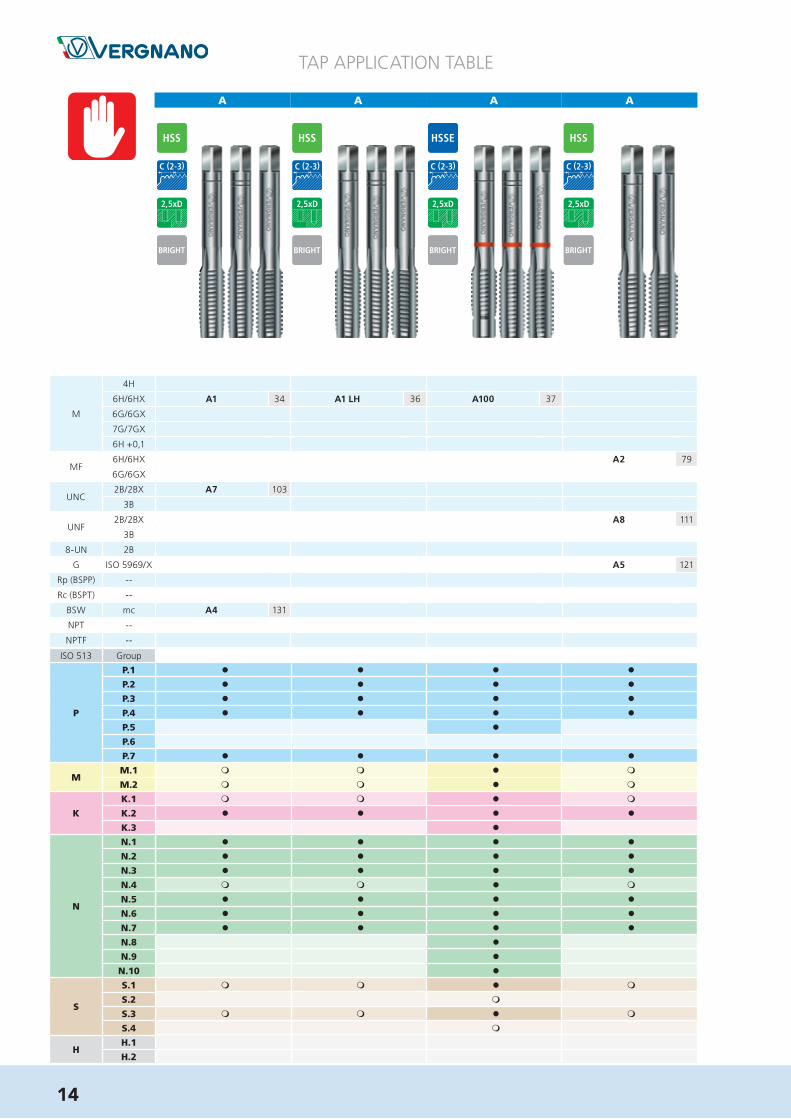
A A A A A A A
TAP APPLICATION TABLE
A15 S 47 A15 S 47
A15 S 45 A15 S 45 A15 S 45 A15 S 45
A15 S 48 A15 S 48
A15 S 49 A15 S 49
A17 S 87 A17 S 87 A17 S 87 A17 S 87 A17 S 90
A17 S 91 A17 S 91
A27 FP 104 A27 FP 104 A19 S 106 A19 S 106 A19 S 106 A19 S 107
A19 S 106
A28 FP 112 A28 FP 112 A20 S 114 A20 S 114 A20 S 114 A20 S 115
A20 S 114
A119 119 A119 119
A26 FP 122 A18 S 124 A18 S 124 A18 S 124 A18 S 124
A24 FP 132
TiX2
ISO 513 Group
P
P.1
P.2
P.3
P.4
P.5
P.6
P.7
MM.1
M.2
K
K.1
K.2
K.3
N
N.1
N.2
N.3
N.4
N.5
N.6
N.7
N.8
N.9
N.10
S
S.1
S.2
S.3
S.4
HH.1
H.2
M
4H
6H/6HX
6G/6GX
7G/7GX
6H +0,1
MF6H/6HX
6G/6GX
UNC2B/2BX
3B
UNF2B/2BX
3B
8-UN 2B
G ISO 5969/X
Rp (BSPP) --
Rc (BSPT) --
BSW mc
NPT --
NPTF --
m 12-15 l 20-25 m 18-20 m 18-20 m 30-35 m 30-35
l 10-12 l 15-20 l 20-25 l 20-25 l 30-35 l 30-35
l 8-10 l 12-15 l 15-20 l 15-20 l 25-30 l 25-30
l 12-15 l 12-15 l 20-25 l 20-25
m 3-5 m 3-5 l 10-15 l 10-15
m 5-7 m 5-7 l 10-15 l 10-15 l 10-15
m 5-7 m 5-7 l 10-15 l 10-15 l 10-15
m 2-3 m 2-3 m 6-8 m 6-8 m 6-8
l 8-10 l 12-15 l 15-20 l 15-20 l 25-30 l 25-30
m 12-15 l 20-25 m 18-20 m 18-20 m 30-35 m 30-35
m 10-12 m 15-20 l 20-25 l 20-25 l 30-35 l 30-35
m 10-12 m 15-20 l 20-25 l 20-25 l 30-35 l 30-35
m 10-12 l 15-20 m 15-18 m 15-18 m 25-30 m 25-30
m 8-10 m 12-15 l 15-18 l 15-18 l 25-30 l 25-30
m 8-10 m 8-10
m 8-10 m 8-10 m 12-15 m 12-15
16
In order to select the correct tap, follow steps 1 to 9.
1 Material2 Material subgroup3 Hole type4 Thread depth5 Thread type6 Tolerance7 Coating8 Tool code (page)9 Cutting parameters
12
56
3
4
8
7
9
8

G U I D E T O T A P D A T A S H E E T S
MDIN 13
ø d 1
L1
L2
ø d 2 a
Ød1 P L1 L2 L3 Ød2 a zP17TiN
P17TiH1
P17 6GXTiH1
BP17TiH1
js 16 h9 h12
[mm] [mm] [mm] [mm] [mm] [mm] [mm] [-] [mm]
M 8 1 90 16 - 6 4,9 3 7 • • • •10 1 90 18 - 7 5,5 3 9 • • • •10 1,25 100 18 - 7 5,5 3 8,8 • • • •12 1 100 22 - 9 7 4 11 • • •12 1,25 100 22 - 9 7 4 10,8 • • • •12 1,5 100 22 - 9 7 4 10,5 • • • •14 1,5 100 22 - 11 9 4 12,5 • • • •16 1,5 100 22 - 12 9 4 14,5 • • • •18 1,5 110 25 - 14 11 4 16,5 • • • •20 1,5 125 25 - 16 12 4 18,5 • • • •
APPLICATION RANGE - CUTTING SPEED m/min
ISO MG P17TiN
P17TiH1
P17 6GXTiH1
BP17TiH1
P
P.3 l 25-35 l 25-35 l 25-35 l 25-35
P.4 l 20-30 l 20-30 l 20-30 l 20-30
P.5 l 10-20 l 10-20 l 10-20 l 10-20
P.6 l 8-10 l 8-10 l 8-10 l 8-10
P.7 l 10-20 l 10-20 l 10-20 l 10-20
MM.1 l 10-20 l 10-20 l 10-20 l 10-20
M.2 l 6-8 l 6-8 l 6-8 l 6-8
K K.2 l 25-35 l 25-35 l 25-35 l 25-35
NN.2-3 l 30-40 l 30-40 l 30-40 l 30-40
N.6 l 25-35 l 25-35 l 25-35 l 25-35
HIGH PERFORMANCE MACHINE TAPS for through holesStraight flutes with spiral point
DIN 374
158 P.46
MFDIN 13
P17TiH1
P17TiN
P17 6GXTiH1
BP17TiH1
P SER
IES
1 Thread type2 Application characteristics3 Dimensional standard4 Recommended application range5 Sizes6 Price list page reference7 (•) Standard execution
8 Through coolant9 Direction of cut10 Hole type11 Chamfer form12 Tolerance13 Coating14 Tool code
1
2
3
4
5
6
7
12
11
10
9
8
13
14
9

G U I D E T O T H R E A D M I L L S D ATA S H E E T S
SOLID CARBIDE THREAD MILLSSpiral flutes
218 P.64
L2
Ø D
L1
Ø D
2
P M ØD2 ØD z L2 L1 VR40TiAIN
VR45TiAIN
h6
[mm] [mm] [mm] [-] [mm] [mm]
0,3 M1,4 3 1,05 3 4 39 VR45010I0300400
0,35 M1,6 3 1,2 3 4,8 39 VR45012I0350400
0,4 M2 6 1,53 3 4,5 58 VR40015I0400400
0,4 M2 3 1,53 3 6 39 VR45015I0400600
0,5 M3 6 2,37 3 6,5 58 VR40023I0500600
0,5 M3 6 2,37 3 9,5 58 VR45023I0500900
0,5 M3 6 2,37 3 9,5 105 VR45023I050090L
0,7 M4 6 3,1 3 9 58 VR40031I0700900
0,7 M4 6 3,1 3 12,5 58 VR45031I0701200
0,7 M4 6 3,1 3 12,5 105 VR45031I070120L
0,8 M5 6 3,8 3 12,5 58 VR40038I0801200
0,8 M5 6 3,8 3 16 58 VR45038I0801600
0,8 M5 6 3,8 3 16 105 VR45038I080160L
1 M6 6 4,65 3 14 58 VR40046I1001400
1 M6 6 4,65 3 20 58 VR45046I1002000
1 M6 6 4,65 3 20 105 VR45046I100200L
1,25 M8 6 5,95 3 18 58 VR40059I1251800
1,25 M8 6 6 3 24 58 VR45060I1252400
1,5 M10 8 7,8 3 23 64 VR40078I1502300
1,75 M12 10 9 3 26 73 VR40090I1752600
2 M16 12 11,8 4 35 84 VR40118I2003500
APPLICATION RANGE
ISO VR40TiAIN
VR45TiAIN
P l l
M l l
K l l
N l l
S l l
VR45TiAIN
VR40TiAIN
For cutting data see page 215
ISODIN 13
L2
Ø D
L1
Ø D
2
VR40
VR45
VR SE
RIE
S
1 Thread type2 Application characteristics3 Technical Drawing4 Application range5 Sizes6 Price list page reference
7 Tool code8 Direction of cut9 Hole type10 Thread11 Coating12 Tool code
1
2
3
4
5
6
7
10
9
8
11
12
10

G U I D E T O T A P P I N G A T T A C H M E N T S D A T A S H E E T S
228 P.67
SYNCHRONOUS ER TAPPING ATTACHMENT with QUICK-CHANGE TAP ADAPTORWith internal through coolant capability (1)
Article Code Attachment Tap Size L ø D ø d ER collet L1 LTOT
ø D1 [mm] [mm] [mm] [mm] [mm] [mm]
VA01A06302CH160 HSK-A63 M3 - M8 64 43 20 ER 16 20,5 84,5
VA01A06302CH250 HSK-A63 M6 - M20 97 60 32 ER 25 23,5 120,5
VA01A10002CH400 HSK-A100 M14 - M33 115 87 50 ER 40 28,5 143,5
SYNCHRONOUS ER TAPPING ATTACHMENT with QUICK-CHANGE TAP ADAPTORWith internal through coolant capability (1)
DIN 1835 B+E
Article Code Attachment Tap Size L ø D ø d ER collet L1 LTOT
ø D1 [mm] [mm] [mm] [mm] [mm] [mm]
VA01C02502CH160 25 M3 - M8 34 43 20 ER 16 20,5 54,5
VA01C02502CH250 25 M6 - M20 56 60 32 ER 25 23,5 79,5
VA01C04002CH400 40 M14 - M33 80 87 50 ER 40 28,5 108,5
VA
SER
IES
DIN 69893 HSK A
DD 1 d
L TOT
L L1
DD1 d
LTOT
L L1
(1) For coolant pressure above 50 bars a special nut screw is available on request
1 Application characteristics2 Technical Drawing3 Size4 Tool code5 Price list page reference
1
2
3
4
5
11

G U I D E T O T A P P F I N D E R A P P
4Select cutting or forming tap
5Select thread type
6Select thread tolerance
Download TAppFinder for iOS or Andriod
1-2Select material to machine
3Select type of hole
12

13
11Browse available sizes
12Browse technical properties
13Browse working parameters
7From results select suitable tap
8Select tap series
9Select thread depth
10Select tap
14
A A A
l l l l
l l l l
l l l l
l l l l
l
l l l l
m m l m
m m l m
m m l m
l l l l
l
l l l l
l l l l
l l l l
m m l m
l l l l
l l l l
l l l l
l
l
l
m m l m
m
m m l m
m
A1 34 A1 LH 36 A100 37
A2 79
A7 103
A8 111
A5 121
A4 131
ISO 513 Group
P
P.1
P.2
P.3
P.4
P.5
P.6
P.7
MM.1
M.2
K
K.1
K.2
K.3
N
N.1
N.2
N.3
N.4
N.5
N.6
N.7
N.8
N.9
N.10
S
S.1
S.2
S.3
S.4
HH.1
H.2
M
4H
6H/6HX
6G/6GX
7G/7GX
6H +0,1
MF6H/6HX
6G/6GX
UNC2B/2BX
3B
UNF2B/2BX
3B
8-UN 2B
G ISO 5969/X
Rp (BSPP) --
Rc (BSPT) --
BSW mc
NPT --
NPTF --
TAP APPLICATION TABLE
A
A A A A
TAP APPLICATION TABLE
15
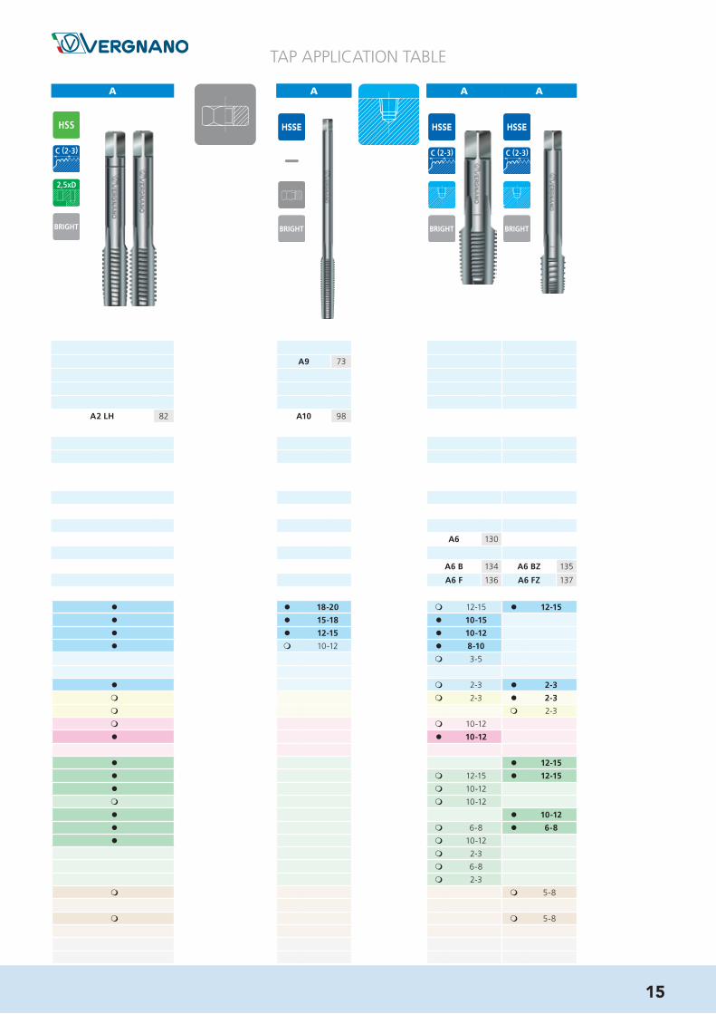
l l 18-20 m 12-15 l 12-15
l l 15-18 l 10-15
l l 12-15 l 10-12
l m 10-12 l 8-10
m 3-5
l m 2-3 l 2-3
m m 2-3 l 2-3
m m 2-3
m m 10-12
l l 10-12
l l 12-15
l m 12-15 l 12-15
l m 10-12
m m 10-12
l l 10-12
l m 6-8 l 6-8
l m 10-12
m 2-3
m 6-8
m 2-3
m m 5-8
m m 5-8
A9 73
A2 LH 82 A10 98
A6 130
A6 B 134 A6 BZ 135
A6 F 136 A6 FZ 137
A A A

A A A A A A A
TAP APPLICATION TABLE
A15 S 47 A15 S 47
A15 S 45 A15 S 45 A15 S 45 A15 S 45
A15 S 48 A15 S 48
A15 S 49 A15 S 49
A17 S 87 A17 S 87 A17 S 87 A17 S 87 A17 S 90
A17 S 91 A17 S 91
A27 FP 104 A27 FP 104 A19 S 106 A19 S 106 A19 S 106 A19 S 107
A19 S 106
A28 FP 112 A28 FP 112 A20 S 114 A20 S 114 A20 S 114 A20 S 115
A20 S 114
A119 119 A119 119
A26 FP 122 A18 S 124 A18 S 124 A18 S 124 A18 S 124
A24 FP 132
TiX2
ISO 513 Group
P
P.1
P.2
P.3
P.4
P.5
P.6
P.7
MM.1
M.2
K
K.1
K.2
K.3
N
N.1
N.2
N.3
N.4
N.5
N.6
N.7
N.8
N.9
N.10
S
S.1
S.2
S.3
S.4
HH.1
H.2
M
4H
6H/6HX
6G/6GX
7G/7GX
6H +0,1
MF6H/6HX
6G/6GX
UNC2B/2BX
3B
UNF2B/2BX
3B
8-UN 2B
G ISO 5969/X
Rp (BSPP) --
Rc (BSPT) --
BSW mc
NPT --
NPTF --
m 12-15 l 20-25 m 18-20 m 18-20 m 30-35 m 30-35
l 10-12 l 15-20 l 20-25 l 20-25 l 30-35 l 30-35
l 8-10 l 12-15 l 15-20 l 15-20 l 25-30 l 25-30
l 12-15 l 12-15 l 20-25 l 20-25
m 3-5 m 3-5 l 10-15 l 10-15
m 5-7 m 5-7 l 10-15 l 10-15 l 10-15
m 5-7 m 5-7 l 10-15 l 10-15 l 10-15
m 2-3 m 2-3 m 6-8 m 6-8 m 6-8
l 8-10 l 12-15 l 15-20 l 15-20 l 25-30 l 25-30
m 12-15 l 20-25 m 18-20 m 18-20 m 30-35 m 30-35
m 10-12 m 15-20 l 20-25 l 20-25 l 30-35 l 30-35
m 10-12 m 15-20 l 20-25 l 20-25 l 30-35 l 30-35
m 10-12 l 15-20 m 15-18 m 15-18 m 25-30 m 25-30
m 8-10 m 12-15 l 15-18 l 15-18 l 25-30 l 25-30
m 8-10 m 8-10
m 8-10 m 8-10 m 12-15 m 12-15
16

A A A A A A A A
TAP APPLICATION TABLE
m 18-20 m 30-35 m 18-20 m 30-35 l 18-20 l 30-35 l 18-20 l 30-35
l 20-25 l 30-35 l 20-25 l 30-35 l 15-18 l 25-30
l 15-20 l 25-30 l 15-20 l 25-30 l 12-15 l 20-25
l 12-15 l 20-25 l 12-15 l 20-25 m 10-12 m 15-20
m 3-5 l 10-15 m 3-5 l 10-15
m 5-7 l 10-15 m 5-7 l 10-15 m 3-5 m 6-8
m 5-7 l 10-15 m 5-7 l 10-15 m 3-5 m 6-8
m 2-3 m 6-8 m 2-3 m 6-8 m 2-3 m 3-5
l 15-20 l 25-30 l 15-20 l 25-30 m 12-15 m 20-25
m 18-20 m 30-35 m 18-20 m 30-35 l 18-20 l 30-40 l 18-20 m 30-35
l 20-25 l 30-35 l 20-25 l 30-35 l 15-18 l 30-40 l 15-18 l 25-30
l 20-25 l 30-35 l 20-25 l 30-35 m 15-18 m 25-30
m 15-18 m 25-30 m 15-18 m 25-30 l 15-18 l 30-35 l 15-18 m 25-30
l 15-18 l 25-30 l 15-18 l 25-30 l 12-15 l 30-35 l 12-15 l 20-25
m 8-10 m 8-10 m 6-8 m 6-8
m 8-10 m 12-15 m 8-10 m 12-15 m 6-8 m 8-10
A15 S LH 50 A15 S LH 50 A16 S 51 A16 S 51 A15 AZ 52 A15 AZ 52 A15 L 53 A15 L 53
17
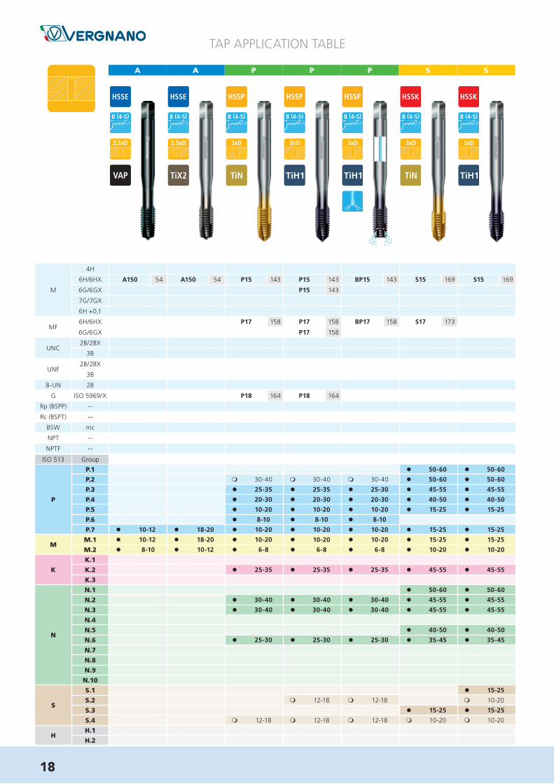
A A P P P S S
TAP APPLICATION TABLE
A150 54 A150 54 P15 143 P15 143 BP15 143 S15 169 S15 169
P15 143
P17 158 P17 158 BP17 158 S17 173
P17 158
P18 164 P18 164
ISO 513 Group
P
P.1
P.2
P.3
P.4
P.5
P.6
P.7
MM.1
M.2
K
K.1
K.2
K.3
N
N.1
N.2
N.3
N.4
N.5
N.6
N.7
N.8
N.9
N.10
S
S.1
S.2
S.3
S.4
HH.1
H.2
M
4H
6H/6HX
6G/6GX
7G/7GX
6H +0,1
MF6H/6HX
6G/6GX
UNC2B/2BX
3B
UNF2B/2BX
3B
8-UN 2B
G ISO 5969/X
Rp (BSPP) --
Rc (BSPT) --
BSW mc
NPT --
NPTF --
TiX2
l 50-60 l 50-60
m 30-40 m 30-40 m 30-40 l 50-60 l 50-60
l 25-30 l 25-30 l 25-30 l 45-55 l 45-55
l 20-30 l 20-30 l 20-30 l 40-50 l 40-50
l 10-20 l 10-20 l 10-20 l 15-25 l 15-25
l 8-10 l 8-10 l 8-10
l 10-12 l 18-20 l 10-20 l 10-20 l 10-20 l 15-25 l 15-25
l 10-12 l 18-20 l 10-20 l 10-20 l 10-20 l 15-25 l 15-25
l 8-10 l 10-12 l 6-8 l 6-8 l 6-8 l 10-20 l 10-20
l 25-35 l 25-35 l 25-35 l 45-55 l 45-55
l 50-60 l 50-60
l 30-40 l 30-40 l 30-40 l 45-55 l 45-55
l 30-40 l 30-40 l 30-40 l 45-55 l 45-55
l 40-50 l 40-50
l 25-30 l 25-30 l 25-30 l 35-45 l 35-45
m 12-18 m 12-18 m 15-25
m 10-20
l 15-25 l 15-25
m 12-18 m 12-18 m 12-18 m 10-20 m 10-20
l 50-60 l 50-60
m 30-40 m 30-40 m 30-40 l 50-60 l 50-60
l 25-35 l 25-35 l 25-30 l 45-55 l 45-55
l 20-30 l 20-30 l 20-30 l 40-50 l 40-50
l 10-20 l 10-20 l 10-20 l 15-25 l 15-25
l 8-10 l 8-10 l 8-10
l 10-12 l 18-20 l 10-20 l 10-20 l 10-20 l 15-25 l 15-25
l 10-12 l 18-20 l 10-20 l 10-20 l 10-20 l 15-25 l 15-25
l 8-10 l 10-12 l 6-8 l 6-8 l 6-8 l 10-20 l 10-20
l 25-35 l 25-35 l 25-35 l 45-55 l 45-55
l 50-60 l 50-60
l 30-40 l 30-40 l 30-40 l 45-55 l 45-55
l 30-40 l 30-40 l 30-40 l 45-55 l 45-55
l 40-50 l 40-50
l 25-30 l 25-30 l 25-30 l 35-45 l 35-45
l 15-25
m 12-18 m 12-18 m 10-20
l 15-25 l 15-25
m 12-18 m 12-18 m 12-18 m 10-20 m 10-20
18

S A A A A A A
TAP APPLICATION TABLE
BS15 169 A21 FC 38 A21 FC 38 A22 FC 40 A22 FC 40 A29 55
A29 57
A23 FC 83 A23 FC LH 83 A23 FC 83 A30 92
A27 FC 104 A27 FC 104 A33 108
A33 108
A28 FC 112 A28 FC 112 A34 116
A34 116
A26 FC 122 A32 125
A24 FC 132 A31 133
l 50-60 m 12-15 m 12-15 l 20-25 m 12-15 l 20-25 l 18-20
l 50-60 l 10-12 l 10-12 l 15-20 l 10-12 l 15-20 l 15-18
l 45-55 l 8-10 l 8-10 l 12-15 l 8-10 l 12-15 l 12-15
l 40-50 l 10-12
l 15-25
l 15-25
l 15-25
l 10-20
l 45-55 l 8-10 l 8-10 l 12-15 l 8-10 l 12-15 l 12-15
l 50-60 m 12-15 m 12-15 l 20-25 m 12-15 l 20-25 l 18-20
l 45-55 m 10-12 m 10-12 m 15-20 m 10-12 m 15-20 l 15-18
l 45-55 m 10-12 m 10-12 m 15-20 m 10-12 m 15-20 l 15-18
l 40-50 m 10-12 m 10-12 l 15-20 m 10-12 l 15-20 l 15-18
l 35-45 m 8-10 m 8-10 m 12-15 m 8-10 m 12-15 l 12-15
l 15-25 m 6-8
m 10-20
l 15-25 m 6-8
m 10-20
19

A A A A A A A
TAP APPLICATION TABLE
A70 S 61
A29 55 A29 55 A29 376 58 A29 376 58 A29 L 59 A29 L 59 A70 S 60
A29 57 A70 S 62
A70 S 63
A701 S 64
A30 92 A71 S 95
A71 S 97
A33 108 A60 S 109
A34 116 A61 S 117
A160 120
A32 125 A59 S 126
A159 S 129
A31 133
ISO 513 Group
P
P.1
P.2
P.3
P.4
P.5
P.6
P.7
MM.1
M.2
K
K.1
K.2
K.3
N
N.1
N.2
N.3
N.4
N.5
N.6
N.7
N.8
N.9
N.10
S
S.1
S.2
S.3
S.4
HH.1
H.2
M
4H
6H/6HX
6G/6GX
7G/7GX
6H +0,1
MF6H/6HX
6G/6GX
UNC2B/2BX
3B
UNF2B/2BX
3B
8-UN 2B
G ISO 5969/X
Rp (BSPP) --
Rc (BSPT) --
BSW mc
NPT --
NPTF --
l 50-60 l 50-60
m 30-40 m 30-40 m 30-40 l 50-60 l 50-60
l 25-30 l 25-30 l 25-30 l 45-55 l 45-55
l 20-30 l 20-30 l 20-30 l 40-50 l 40-50
l 10-20 l 10-20 l 10-20 l 15-25 l 15-25
l 8-10 l 8-10 l 8-10
l 10-12 l 18-20 l 10-20 l 10-20 l 10-20 l 15-25 l 15-25
l 10-12 l 18-20 l 10-20 l 10-20 l 10-20 l 15-25 l 15-25
l 8-10 l 10-12 l 6-8 l 6-8 l 6-8 l 10-20 l 10-20
l 25-35 l 25-35 l 25-35 l 45-55 l 45-55
l 50-60 l 50-60
l 30-40 l 30-40 l 30-40 l 45-55 l 45-55
l 30-40 l 30-40 l 30-40 l 45-55 l 45-55
l 40-50 l 40-50
l 25-30 l 25-30 l 25-30 l 35-45 l 35-45
m 12-18 m 12-18 m 15-25
m 10-20
l 15-25 l 15-25
m 12-18 m 12-18 m 12-18 m 10-20 m 10-20
l 18-20 l 30-35 l 18-20 l 30-35 l 18-20 l 30-35
l 15-18 l 25-30 l 15-18 l 25-30 l 15-18 l 25-30 l 15-20
l 12-15 l 20-25 l 12-15 l 20-25 l 12-15 l 20-25 l 12-15
l 10-12 l 15-20 l 10-12 l 15-20 l 10-12 l 15-20 l 10-12
l 5-10 l 5-10 l 5-10 m 6-8
m 6-8
m 6-8
l 12-15 l 20-25 l 12-15 l 20-25 l 12-15 l 20-25 l 12-15
l 18-20 m 30-35 l 18-20 m 30-35 l 18-20 m 30-35
l 15-18 l 25-30 l 15-18 l 25-30 l 15-18 l 25-30 m 18-20
l 15-18 l 25-30 l 15-18 l 25-30 l 15-18 l 25-30 l 15-18
l 15-18 m 25-30 l 15-18 m 25-30 l 15-18 m 25-30
l 12-15 l 20-25 l 12-15 l 20-25 l 12-15 l 20-25 l 15-18
m 6-8 m 6-8 m 6-8 m 6-8
m 6-8 m 8-10 m 6-8 m 8-10 m 6-8 m 8-10 m 6-8
20

A A A A A A A A
TAP APPLICATION TABLE
l 15-20 l 25-30 l 25-30 l 15-20 l 25-30 l 15-20 l 25-30
l 12-15 l 20-25 l 20-25 l 12-15 l 20-25 l 12-15 l 20-25
l 10-12 l 15-20 l 15-20 l 10-12 l 15-20 l 10-12 l 15-20
m 6-8 l 5-10 l 5-10 m 6-8 l 5-10 m 6-8 l 5-10
m 6-8 l 8-10 l 8-10 l 8-10 m 6-8 l 8-10 m 6-8 l 8-10
m 6-8 l 8-10 l 8-10 l 8-10 m 6-8 l 8-10 m 6-8 l 8-10
m 3-5 m 3-5 l 5-7 m 3-5 m 3-5
l 12-15 l 20-25 l 20-25 l 12-15 l 20-25 l 12-15 l 20-25
m 18-20 m 30-35 m 30-35 m 18-20 m 30-35 m 18-20 m 30-35
l 15-18 l 25-30 l 25-30 l 15-18 l 25-30 l 15-18 l 25-30
l 15-18 l 25-30 l 25-30 l 15-18 l 25-30 l 15-18 l 25-30
m 6-8 m 6-8 m 6-8
m 6-8 m 8-10 m 8-10 m 6-8 m 8-10 m 6-8 m 8-10
A70 S 61
A70 S 60 A70 S 60 A70 S 60 A70 SE 65 A70 SE 65 A70 S LH 66 A70 S LH 66
A70 S 62
A70 S 63
A701 S 64
A71 S 95 A71 S 95 A71 S 95 A71 S 96
A71 S 97
A60 S 109 A60 S 109 A60 S 109
A61 S 117 A61 S 117 A61 S 117
A160 120
A59 S 126 A59 S 126 A59 S 126 A59 S 127
A159 S 129
TiX2
21

A A A A A A A
TAP APPLICATION TABLE
A76 S 67 A76 S 67 A70 L 68 A70 L 68 A120 69 A120 69 A120 69
ISO 513 Group
P
P.1
P.2
P.3
P.4
P.5
P.6
P.7
MM.1
M.2
K
K.1
K.2
K.3
N
N.1
N.2
N.3
N.4
N.5
N.6
N.7
N.8
N.9
N.10
S
S.1
S.2
S.3
S.4
HH.1
H.2
M
4H
6H/6HX
6G/6GX
7G/7GX
6H +0,1
MF6H/6HX
6G/6GX
UNC2B/2BX
3B
UNF2B/2BX
3B
8-UN 2B
G ISO 5969/X
Rp (BSPP) --
Rc (BSPT) --
BSW mc
NPT --
NPTF --
l 50-60 l 50-60
m 30-40 m 30-40 m 30-40 l 50-60 l 50-60
l 25-30 l 25-30 l 25-30 l 45-55 l 45-55
l 20-30 l 20-30 l 20-30 l 40-50 l 40-50
l 10-20 l 10-20 l 10-20 l 15-25 l 15-25
l 8-10 l 8-10 l 8-10
l 10-12 l 18-20 l 10-20 l 10-20 l 10-20 l 15-25 l 15-25
l 10-12 l 18-20 l 10-20 l 10-20 l 10-20 l 15-25 l 15-25
l 8-10 l 10-12 l 6-8 l 6-8 l 6-8 l 10-20 l 10-20
l 25-35 l 25-35 l 25-35 l 45-55 l 45-55
l 50-60 l 50-60
l 30-40 l 30-40 l 30-40 l 45-55 l 45-55
l 30-40 l 30-40 l 30-40 l 45-55 l 45-55
l 40-50 l 40-50
l 25-30 l 25-30 l 25-30 l 35-45 l 35-45
m 12-18 m 12-18 m 15-25
m 10-20
l 15-25 l 15-25
m 12-18 m 12-18 m 12-18 m 10-20 m 10-20
l 12-15 l 25-30 l 12-15 l 12-15 l 25-30
l 15-20 l 25-30 l 10-15 l 20-25 l 10-15 l 10-15 l 20-25
l 12-15 l 20-25 m 8-10 m 15-20 m 8-10 m 8-10 m 15-20
l 10-12 l 15-20
m 6-8 l 5-10
m 6-8 l 8-10
m 6-8 l 8-10
m 3-5
l 12-15 l 20-25 m 8-10 m 15-20 m 8-10 m 8-10 m 15-20
l 12-15 m 25-30 l 12-15 l 12-15 m 25-30
m 18-20 m 30-35 l 12-15 l 25-30 l 12-15 l 12-15 l 25-30
l 15-18 l 25-30 m 10-12 m 20-25 m 10-12 m 10-12 m 20-25
l 10-12 m 20-25 l 10-12 l 10-12 m 20-25
l 15-18 l 25-30 l 10-12 l 20-25 l 10-12 l 10-12 l 20-25
m 6-8
m 6-8 m 8-10
22
A A A A A A P P
TAP APPLICATION TABLE
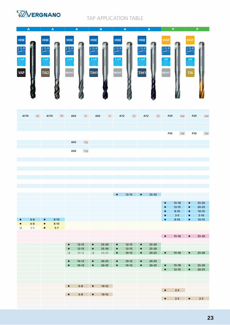
l 12-15 l 25-30
l 15-18 l 25-30
l 12-15 l 20-25
l 8-10 l 10-15
l 3-5 l 5-10
l 6-8 l 8-10 l 8-10 l 10-15
l 6-8 l 8-10
m 3-5 l 5-7
l 15-18 l 25-30
l 12-15 l 25-30 l 12-15 l 25-30
l 12-15 l 25-30 l 12-15 l 25-30
m 10-12 m 20-25 l 10-12 l 20-25 l 15-18 l 25-30
l 10-12 l 20-25 l 10-12 l 20-25
l 10-12 l 20-25 l 10-12 l 20-25 l 15-18 l 25-30
l 12-15 l 20-25
l 6-8 l 10-12
l 2-3
l 6-8 l 10-12
l 2-3 l 2-3
A170 70 A170 70 A62 71 A62 71 A72 72 A72 72 P29 144 P29 144
P30 159 P30 159
A65 110
A66 118
TiX2
23

P P P P P P P
TAP APPLICATION TABLE
ISO 513 Group
P
P.1
P.2
P.3
P.4
P.5
P.6
P.7
MM.1
M.2
K
K.1
K.2
K.3
N
N.1
N.2
N.3
N.4
N.5
N.6
N.7
N.8
N.9
N.10
S
S.1
S.2
S.3
S.4
HH.1
H.2
M
4H
6H/6HX
6G/6GX
7G/7GX
6H +0,1
MF6H/6HX
6G/6GX
UNC2B/2BX
3B
UNF2B/2BX
3B
8-UN 2B
G ISO 5969/X
Rp (BSPP) --
Rc (BSPT) --
BSW mc
NPT --
NPTF --
m 25-35 m 25-35 m 25-35 m 25-35
l 25-30 l 25-30 l 25-30 l 20-30 l 20-30 l 20-30 l 20-30
l 20-25 l 20-25 l 20-25 l 15-25 l 15-25 l 15-25 l 15-25
l 10-15 l 10-15 l 10-15 l 5-15 l 5-15 l 5-15 l 5-15
l 5-10 l 5-10 l 5-10 m 5-8 m 5-8 m 5-8 m 5-8
l 10-15 l 10-15 l 10-15 l 10-15 l 10-15 l 10-15 l 10-15
l 10-15 l 10-15 l 10-15 l 10-15
l 5-7 l 5-7 l 5-7 l 5-7
l 25-30 l 25-30 l 25-30 l 20-30 l 20-30 l 20-30 l 20-30
m 30-40 m 30-40 m 30-40 m 30-40
l 25-30 l 25-30 l 25-30 l 25-35 l 25-35 l 25-35 l 25-35
l 25-30 l 25-30 l 25-30 l 25-35 l 25-35 l 25-35 l 25-35
l 20-25 l 20-25 l 20-25
l 10-15 l 10-15
l 2-3 l 2-3 l 2-3
l 10-15 l 10-15 l 10-15 l 10-15
l 2-3 l 2-3 l 2-3
P29 144 BP29 144 P29 E 145 P70 146 P70 146 BP70 147 P70 E 148
P70 146
P70 146
P30 159 BP30 159 P71 160 P71 160 BP71 160
P71 160
P59 165 P59 165
24
P
TAP APPLICATION TABLE
P P S S S P P
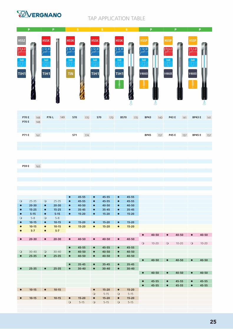
l 45-55 l 45-55 l 45-55
m 25-35 m 25-35 l 45-55 l 45-55 l 45-55
l 20-30 l 20-30 l 40-50 l 40-50 l 40-50
l 15-25 l 15-25 l 35-45 l 35-45 l 35-45
l 5-15 l 5-15 l 15-20 l 15-20 l 15-20
m 5-8 m 5-8
l 10-15 l 10-15 l 15-20 l 15-20 l 15-20
l 10-15 l 10-15 l 15-20 l 15-20 l 15-20
l 5-7 l 5-7
l 40-50 l 40-50 l 40-50
l 20-30 l 20-30 l 40-50 l 40-50 l 40-50
m 10-20 m 10-20 m 10-20
l 45-55 l 45-55 l 45-55
m 30-40 m 30-40 l 40-50 l 40-50 l 40-50
l 25-35 l 25-35 l 40-50 l 40-50 l 40-50
l 40-50 l 40-50 l 40-50
l 35-45 l 35-45 l 35-45
l 25-35 l 25-35 l 30-40 l 30-40 l 30-40
l 40-50 l 40-50 l 40-50
l 45-55 l 45-55 l 45-55
l 45-55 l 45-55 l 45-55
l 10-15 l 10-15 l 15-20 l 15-20
m 5-15 m 5-15
l 10-15 l 10-15 l 15-20 l 15-20 l 15-20
m 5-15 m 5-15 m 5-15
P70 E 148 P76 L 149 S70 170 S70 170 BS70 170 BP43 140 P43 E 141 BP43 E 141
P70 E 148
P71 E 161 S71 174 BP45 157 P45 E 157 BP45 E 157
P59 E 165
25
S S S H H H H
TAP APPLICATION TABLE
ISO 513 Group
P
P.1
P.2
P.3
P.4
P.5
P.6
P.7
MM.1
M.2
K
K.1
K.2
K.3
N
N.1
N.2
N.3
N.4
N.5
N.6
N.7
N.8
N.9
N.10
S
S.1
S.2
S.3
S.4
HH.1
H.2
M
4H
6H/6HX
6G/6GX
7G/7GX
6H +0,1
MF6H/6HX
6G/6GX
UNC2B/2BX
3B
UNF2B/2BX
3B
8-UN 2B
G ISO 5969/X
Rp (BSPP) --
Rc (BSPT) --
BSW mc
NPT --
NPTF --
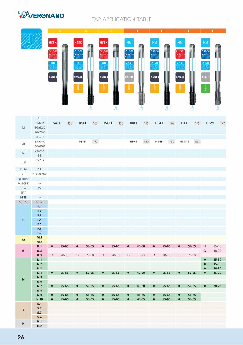
l 55-65 l 55-65 l 55-65 l 40-50 l 55-65 l 55-65 m 15-40
m 10-20
m 20-30 m 20-30 m 20-30 m 10-20 m 20-30 m 20-30
l 15-30
l 15-30
l 20-30
l 55-65 l 55-65 l 55-65 l 40-50 l 55-65 l 55-65 l 15-20
l 55-65 l 55-65 l 55-65 l 40-50 l 55-65 l 55-65 l 20-25
l 55-65 l 55-65 l 55-65 l 45-55 l 55-65 l 55-65
l 55-65 l 55-65 l 55-65 l 45-55 l 55-65 l 55-65
S43 E 168 BS43 168 BS43 E 168 HB43 176 HB43 176 HB43 E 176 HB29 177
BS45 172 HB45 180 HB45 180 HB45 E 180
26

A A A A A A
TAP APPLICATION TABLE
H
NITR NITR
l 12-15 l 20-25
m 40-80 l 15-20 l 40-45 l 15-20 l 40-45
m 15-40
l 25-50 l 12-15 l 20-25
l 25-50 l 10-12 l 15-20
l 30-50
l 25-40 l 15-20 l 40-45 l 15-20 l 40-45
l 10-12 l 15-20
l 8-10 l 12-15
l 30-40 l 15-20 l 40-45 l 15-20 l 40-45
l 20-25 l 45-50 l 20-25 l 45-50
l 20-25 l 45-50 l 20-25 l 45-50
HB29 177 A43 41 A43 41 A44 42 A44 42 A67 43 A67 43
A45 86 A45 86
A49 105 A49 105
A50 113 A50 113
A48 123 A48 123
27

A A A P P P S
TAP APPLICATION TABLE
ISO 513 Group
P
P.1
P.2
P.3
P.4
P.5
P.6
P.7
MM.1
M.2
K
K.1
K.2
K.3
N
N.1
N.2
N.3
N.4
N.5
N.6
N.7
N.8
N.9
N.10
S
S.1
S.2
S.3
S.4
HH.1
H.2
M
4H
6H/6HX
6G/6GX
7G/7GX
6H +0,1
MF6H/6HX
6G/6GX
UNC2B/2BX
3B
UNF2B/2BX
3B
8-UN 2B
G ISO 5969/X
Rp (BSPP) --
Rc (BSPT) --
BSW mc
NPT --
NPTF --
m 12-15
l 10-12
l 8-10
l 2-3 l 5-8
l 40-50 l 55-65
l 8-10
m 10-20 m 20-30
m 12-15
m 10-12
m 10-12
l 40-50 l 55-65
m 10-12
m 8-10
l 40-50 l 55-65
l 3-5 l 8-10
l 45-55 l 55-65
l 45-55 l 55-65
l 6-8 l 10-12
l 3-5 l 6-8
A110 44 A110 44 A190-EG 78 P43 140 P130 142 P130 142 S43 168
P45 157 S45 172
28

H H A A A A P
TAP APPLICATION TABLE
l 40-45 l 40-45 l 40-45 l 40-45 l 40-45
l 40-45 l 40-45 l 40-45 l 40-45 l 40-45
l 35-40 l 35-40 l 35-40 l 35-40 l 35-40
l 30-35
l 15-20
m 2-5 m 5-10
m 15-20 m 15-20 m 15-20 m 15-20 l 15-20
m 15-20 m 15-20 m 15-20 m 15-20 l 15-20
l 40-45 l 40-45 l 40-45 l 40-45 l 40-45
l 40-45 l 40-45 l 40-45 l 40-45 l 40-45
l 35-40 l 35-40 l 35-40 l 35-40 l 35-40
l 40-45 l 40-45 l 40-45 l 40-45 l 40-45
l 40-45 l 40-45 l 40-45 l 40-45 l 40-45
l 10-15
m 5-10
l 2-3 l 3-6
l 1-2 l 2-4
H130 178 H130 178 A80 74 A80 74 A80N 76 A80N 76 P80 150
A80 75 A80 75 A80N 77 A80N 77 P80 150
P80 150
A81 99 A81 99 A81N 101 A81N 101 P81 162
A81 100 A81 100 A81N 102 A81N 102 P81 162
A82N 128 A82N 128
29
TAP APPLICATION TABLE
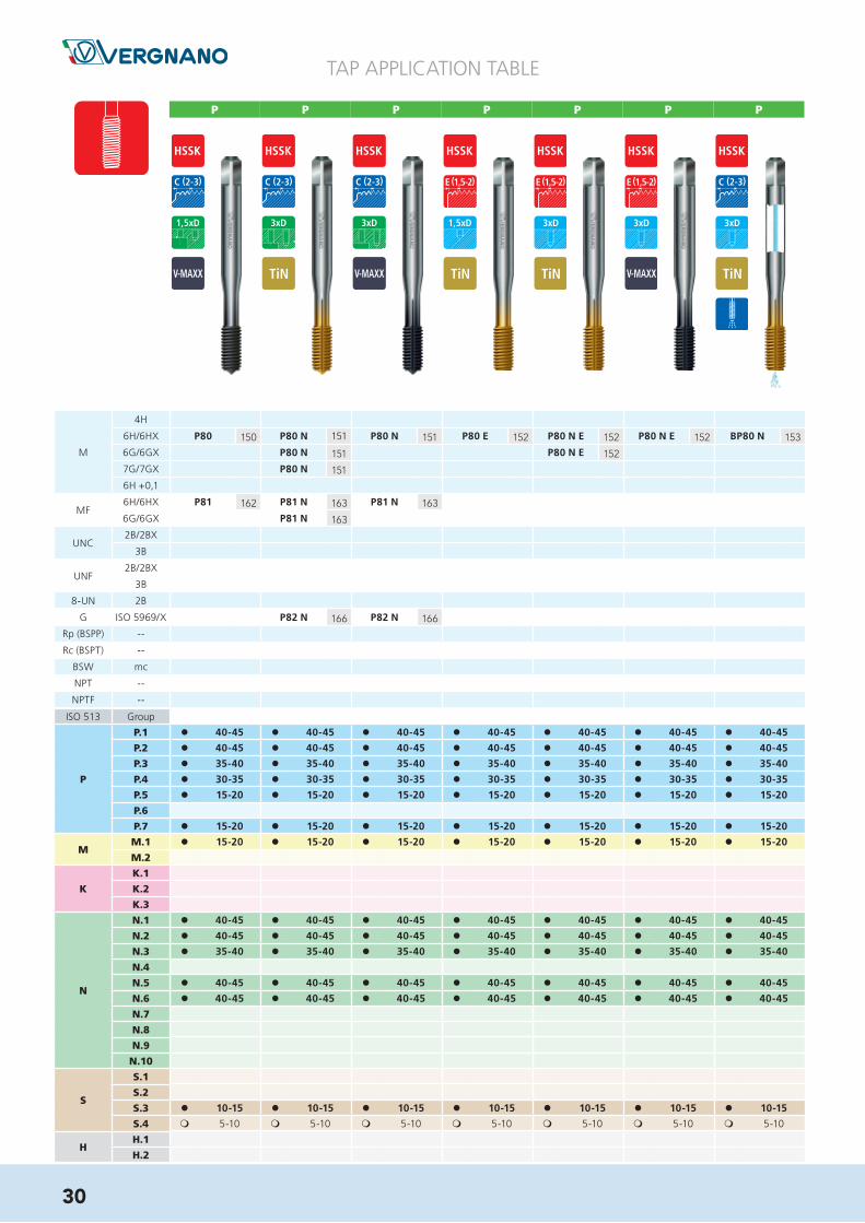
l 40-45 l 40-45 l 40-45 l 40-45 l 40-45 l 40-45 l 40-45
l 40-45 l 40-45 l 40-45 l 40-45 l 40-45 l 40-45 l 40-45
l 35-40 l 35-40 l 35-40 l 35-40 l 35-40 l 35-40 l 35-40
l 30-35 l 30-35 l 30-35 l 30-35 l 30-35 l 30-35 l 30-35
l 15-20 l 15-20 l 15-20 l 15-20 l 15-20 l 15-20 l 15-20
l 15-20 l 15-20 l 15-20 l 15-20 l 15-20 l 15-20 l 15-20
l 15-20 l 15-20 l 15-20 l 15-20 l 15-20 l 15-20 l 15-20
l 40-45 l 40-45 l 40-45 l 40-45 l 40-45 l 40-45 l 40-45
l 40-45 l 40-45 l 40-45 l 40-45 l 40-45 l 40-45 l 40-45
l 35-40 l 35-40 l 35-40 l 35-40 l 35-40 l 35-40 l 35-40
l 40-45 l 40-45 l 40-45 l 40-45 l 40-45 l 40-45 l 40-45
l 40-45 l 40-45 l 40-45 l 40-45 l 40-45 l 40-45 l 40-45
l 10-15 l 10-15 l 10-15 l 10-15 l 10-15 l 10-15 l 10-15
m 5-10 m 5-10 m 5-10 m 5-10 m 5-10 m 5-10 m 5-10
P80 150 P80 N 151 P80 N 151 P80 E 152 P80 N E 152 P80 N E 152 BP80 N 153
P80 N 151 P80 N E 152
P80 N 151
P81 162 P81 N 163 P81 N 163
P81 N 163
P82 N 166 P82 N 166
P P P P P P P
ISO 513 Group
P
P.1
P.2
P.3
P.4
P.5
P.6
P.7
MM.1
M.2
K
K.1
K.2
K.3
N
N.1
N.2
N.3
N.4
N.5
N.6
N.7
N.8
N.9
N.10
S
S.1
S.2
S.3
S.4
HH.1
H.2
M
4H
6H/6HX
6G/6GX
7G/7GX
6H +0,1
MF6H/6HX
6G/6GX
UNC2B/2BX
3B
UNF2B/2BX
3B
8-UN 2B
G ISO 5969/X
Rp (BSPP) --
Rc (BSPT) --
BSW mc
NPT --
NPTF --
30

TAP APPLICATION TABLE
l 40-45 l 40-45 l 40-45 l 40-45 l 40-45 l 50-60
l 40-45 l 40-45 l 40-45 l 40-45 l 40-45 l 50-60
l 35-40 l 35-40 l 35-40 l 35-40 l 35-40 l 45-55
l 30-35 l 30-35 l 30-35 l 30-35 l 30-35 l 40-50
l 15-20 l 15-20 l 15-20 l 15-20 l 15-20 l 20-30
l 15-20 l 15-20 l 15-20 l 15-20 l 15-20 l 15-20 l 15-20 l 25-35
l 15-20 l 15-20 l 15-20 l 15-20 l 15-20 l 10-15 l 10-15 l 25-35
l 8-10 l 8-10 l 15-25
l 40-45 l 40-45 l 40-45 l 40-45 l 40-45 l 50-60
l 40-45 l 40-45 l 40-45 l 40-45 l 40-45 l 50-60
l 35-40 l 35-40 l 35-40 l 35-40 l 35-40 l 45-55
l 40-45 l 40-45 l 40-45 l 40-45 l 40-45 l 50-60
l 40-45 l 40-45 l 40-45 l 40-45 l 40-45 l 50-60
l 10-15 l 10-15 l 10-15 l 10-15 l 10-15 l 10-20
m 5-10 m 5-10 m 5-10 m 5-10 m 5-10 m 5-15
BP80 N R 153 BP80 N R 153 BP80 N E 153 P80 N LH 154 P80 N L 155 P180 N 156 P180 N 156 S80 N 171
S80 N 171
P P P P P P SP
31

TAP APPLICATION TABLE
l 50-60 l 50-60 l 40-50 l 40-50
l 50-60 l 50-60 l 40-50 l 40-50
l 45-55 l 45-55 l 35-45 l 35-45
l 40-50 l 40-50 l 30-40 l 30-40
l 20-30 l 20-30 l 15-25 l 15-25
l 25-35 l 25-35 l 15-25 l 15-25
l 25-35 l 25-35 l 15-25 l 15-25
l 15-25 l 15-25
l 50-60 l 50-60 l 40-50 l 40-50
l 50-60 l 50-60 l 40-50 l 40-50
l 45-55 l 45-55 l 35-45 l 35-45
l 50-60 l 50-60 l 40-50 l 40-50
l 50-60 l 50-60 l 40-50 l 40-50
l 10-20 l 10-20 l 10-20 l 10-20
m 5-15 m 5-15 m 5-15 m 5-15
S80 N 171 BS80 N R 171 HB80 N R 179
HB81 N R E 181
S S H H
ISO 513 Group
P
P.1
P.2
P.3
P.4
P.5
P.6
P.7
MM.1
M.2
K
K.1
K.2
K.3
N
N.1
N.2
N.3
N.4
N.5
N.6
N.7
N.8
N.9
N.10
S
S.1
S.2
S.3
S.4
HH.1
H.2
M
4H
6H/6HX
6G/6GX
7G/7GX
6H +0,1
MF6H/6HX
6G/6GX
UNC2B/2BX
3B
UNF2B/2BX
3B
8-UN 2B
G ISO 5969/X
Rp (BSPP) --
Rc (BSPT) --
BSW mc
NPT --
NPTF --
32
VTO-100
Suitable for tapping withcutting or forming taps
on all materials.Available only in
EU countries
TAPPING OIL
P.69

MDIN 13
AS E R I E S
Taps for Generic Applications
A SE
RIE
S

MDIN 13
ø d 2
L1
L2
L3
ø d 1
a
ø d 1
L2
ø d 2 a
L1
Ød1 P L1 L2 L3 Ød2 a zA1
ROUGHINGA1
SECONDA1
FINISHINGA1SET
js 16 h9 h12
[mm] [mm] [mm] [mm] [mm] [mm] [mm] [-] [mm]
M 2 0,4 36 7,5 12 2,8 2,1 3 1,6 • • • •2,2 0,45 36 8,5 13,5 2,8 2,1 3 1,75 • • • •2,3 0,4 36 8,5 13,5 2,8 2,1 3 1,9 • • • •2,5 0,45 40 8,5 14,5 2,8 2,1 3 2,05 • • • •2,6 0,45 40 8,5 14,5 2,8 2,1 3 2,1 • • • •3 0,5 40 10 18 3,5 2,7 3 2,5 • • • •3,5 0,6 45 11 20 4 3 3 2,9 • • • •4 0,7 45 12 21 4,5 3,4 3 3,3 • • • •4,5 0,75 50 13 23 6 4,9 3 3,7 • • • •5 0,8 50 14 24 6 4,9 3 4,2 • • • •6 1 56 16 28 6 4,9 3 5 • • • •7 1 56 19 - 6 4,9 3 6 • • • •8 1,25 63 22 - 6 4,9 3 6,8 • • • •9 1,25 63 22 - 7 5,5 3 7,8 • • • •10 1,5 70 24 - 7 5,5 3 8,5 • • • •11 1,5 70 24 - 8 6,2 3 9,5 • • • •12 1,75 75 28 - 9 7 4 10,2 • • • •14 2 80 30 - 11 9 4 12 • • • •16 2 80 32 - 12 9 4 14 • • • •18 2,5 95 34 - 14 11 4 15,5 • • • •20 2,5 95 34 - 16 12 4 17,5 • • • •22 2,5 100 34 - 18 14,5 4 19,5 • • • •24 3 110 38 - 18 14,5 4 21 • • • •27 3 110 38 - 20 16 4 24 • • • •30 3,5 125 45 - 22 18 4 26,5 • • • •33 3,5 125 50 - 25 20 4 29,5 • • • •
A1SET
A1FINISHING
A1SECOND
A1ROUGHING
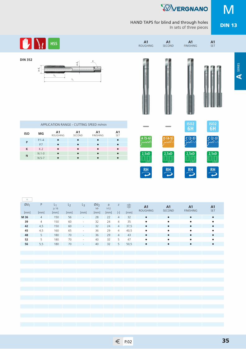
HAND TAPS for blind and through holesIn sets of three pieces
DIN 352≤ M6
DIN 352≥ M7
34 P.02
MDIN 13
A SE
RIE
S
APPLICATION RANGE - CUTTING SPEED m/min
ISO MG A1ROUGHING
A1SECOND
A1FINISHING
A1SET
PP.1-4 l l l l
P.7 l l l l
K K.2 l l l l
NN.1-3 l l l l
N.5-7 l l l l
»
MDIN 13
ø d 1
L2ø
d 2 a
L1
Ød1 P L1 L2 L3 Ød2 a zA1
ROUGHINGA1
SECONDA1
FINISHINGA1SET
js 16 h9 h12
[mm] [mm] [mm] [mm] [mm] [mm] [mm] [-] [mm]
M 36 4 150 56 - 28 22 4 32 • • • •39 4 150 60 - 32 24 4 35 • • • •42 4,5 150 60 - 32 24 4 37,5 • • • •45 4,5 160 65 - 36 29 4 40,5 • • • •48 5 180 70 - 36 29 4 43 • • • •52 5 180 70 - 40 32 5 47 • • • •56 5,5 180 70 - 40 32 5 50,5 • • • •
A1SET
A1FINISHING
A1SECOND
A1ROUGHING
HAND TAPS for blind and through holesIn sets of three pieces
DIN 352
35P.02
APPLICATION RANGE - CUTTING SPEED m/min
ISO MG A1ROUGHING
A1SECOND
A1FINISHING
A1SET
PP.1-4 l l l l
P.7 l l l l
K K.2 l l l l
NN.1-3 l l l l
N.5-7 l l l l
MDIN 13
«
A SE
RIE
S

MDIN 13
ø d 2
L1
L2
L3
ø d 1
a
ø d 1
ø d 2 a
L1
L2
Ød1 P L1 L2 L3 Ød2 a zA1 LH
ROUGHINGA1 LHSECOND
A1 LHFINISHING
A1 LHSET
js 16 h9 h12
[mm] [mm] [mm] [mm] [mm] [mm] [mm] [-] [mm]
M 2,6 0,45 40 8,5 14,5 2,8 2,1 3 2,1 • • • •3 0,5 40 10 18 3,5 2,7 3 2,5 • • • •3,5 0,6 45 11 20 4 3 3 2,9 • • • •4 0,7 45 12 21 4,5 3,4 3 3,3 • • • •5 0,8 50 14 24 6 4,9 3 4,2 • • • •6 1 56 16 28 6 4,9 3 5 • • • •8 1,25 63 22 - 6 4,9 3 6,8 • • • •10 1,5 70 24 - 7 5,5 3 8,5 • • • •12 1,75 75 28 - 9 7 4 10,2 • • • •14 2 80 30 - 11 9 4 12 • • • •16 2 80 32 - 12 9 4 14 • • • •18 2,5 95 34 - 14 11 4 15,5 • • • •20 2,5 95 34 - 16 12 4 17,5 • • • •22 2,5 100 34 - 18 14,5 4 19,5 • • • •24 3 110 38 - 18 14,5 4 21 • • • •27 3 110 38 - 20 16 4 24 • • • •30 3,5 125 45 - 22 18 4 26,5 • • • •
A1 LHSET
A1 LHFINISHING
A1 LHSECOND
A1 LHROUGHING
HAND TAPS for blind and through holesIn sets of three pieces
DIN 352≤ M6
DIN 352≥ M8
36 P.02
APPLICATION RANGE - CUTTING SPEED m/min
ISO MG A1 LHROUGHING
A1 LHSECOND
A1 LHFINISHING
A1 LHSET
PP.1-4 l l l l
P.7 l l l l
K K.2 l l l l
NN.1-3 l l l l
N.5-7 l l l l
MDIN 13
A SE
RIE
S

MDIN 13
ø d 2
L1
L2
L3
ø d 1
a
ø d 1
L2
ø d 2 a
L1
Ød1 P L1 L2 L3 Ød2 a zA100
ROUGHINGA100
SECONDA100
FINISHINGA100
SET js 16 h9 h12
[mm] [mm] [mm] [mm] [mm] [mm] [mm] [-] [mm]
M 2 0,4 36 7,5 13 2,8 2,1 3 1,6 • • • •2,5 0,45 40 9 15 2,8 2,1 3 2,05 • • • •3 0,5 40 10 18 3,5 2,7 3 2,5 • • • •3,5 0,6 45 11 18 4 3 3 2,9 • • • •4 0,7 45 12 21 4,5 3,4 3 3,3 • • • •5 0,8 50 14 24 6 4,9 3 4,2 • • • •6 1 56 16 28 6 4,9 3 5 • • • •8 1,25 63 22 - 6 4,9 4 6,8 • • • •10 1,5 70 24 - 7 5,5 4 8,5 • • • •12 1,75 75 28 - 9 7 4 10,2 • • • •14 2 80 30 - 11 9 4 12 • • • •16 2 80 32 - 12 9 4 14 • • • •18 2,5 95 34 - 14 11 4 15,5 • • • •20 2,5 95 34 - 16 12 4 17,5 • • • •
A100SET
A100FINISHING
A100SECOND
A100ROUGHING
HAND TAPS for blind and through holesIn sets of three pieces
DIN 352≤ M6
DIN 352≥ M8
37P.03
APPLICATION RANGE - CUTTING SPEED m/min
ISO MG A100ROUGHING
A100SECOND
A100FINISHING
A100SET
PP.1-5 l l l l
P.7 l l l l
M M.1-2 l l l l
K K.1-3 l l l l
N N.1-10 l l l l
SS.1 l l l l
S.3 l l l l
MDIN 13
A SE
RIE
S
MDIN 13
ø d 2
L1
L2
L3
ø d 1
a
ø d 1
L1
L2
ø d 2 a
Ød1 P L1 L2 L3 Ød2 a zA21 FCBRIGHT
A21 FCTiN
js 16 h9 h12
[mm] [mm] [mm] [mm] [mm] [mm] [mm] [-] [mm]
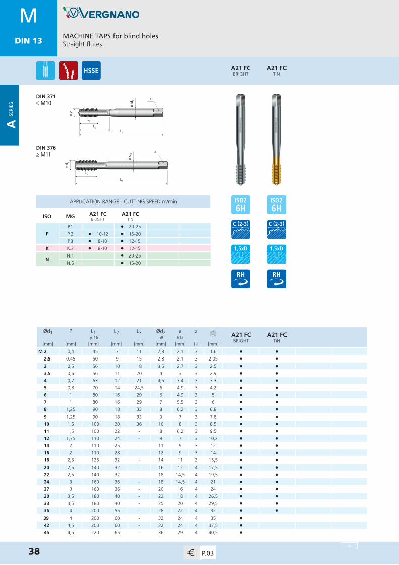
M 2 0,4 45 7 11 2,8 2,1 3 1,6 • •2,5 0,45 50 9 15 2,8 2,1 3 2,05 • •3 0,5 56 10 18 3,5 2,7 3 2,5 • •3,5 0,6 56 11 20 4 3 3 2,9 • •4 0,7 63 12 21 4,5 3,4 3 3,3 • •5 0,8 70 14 24,5 6 4,9 3 4,2 • •6 1 80 16 29 6 4,9 3 5 • •7 1 80 16 29 7 5,5 3 6 • •8 1,25 90 18 33 8 6,2 3 6,8 • •9 1,25 90 18 33 9 7 3 7,8 • •10 1,5 100 20 36 10 8 3 8,5 • •11 1,5 100 22 - 8 6,2 3 9,5 • •12 1,75 110 24 - 9 7 3 10,2 • •14 2 110 25 - 11 9 3 12 • •16 2 110 28 - 12 9 3 14 • •18 2,5 125 32 - 14 11 3 15,5 • •20 2,5 140 32 - 16 12 4 17,5 • •22 2,5 140 32 - 18 14,5 4 19,5 • •24 3 160 36 - 18 14,5 4 21 • •27 3 160 36 - 20 16 4 24 • •30 3,5 180 40 - 22 18 4 26,5 • •33 3,5 180 40 - 25 20 4 29,5 • •36 4 200 55 - 28 22 4 32 • •
39 4 200 60 - 32 24 4 35 •42 4,5 200 60 - 32 24 4 37,5 •45 4,5 220 65 - 36 29 4 40,5 •
APPLICATION RANGE - CUTTING SPEED m/min
ISO MG A21 FCBRIGHT
A21 FCTiN
P
P.1 l 20-25
P.2 l 10-12 l 15-20
P.3 l 8-10 l 12-15
K K.2 l 8-10 l 12-15
NN.1 l 20-25
N.5 l 15-20
A21 FCTiN
A21 FCBRIGHT
MACHINE TAPS for blind holesStraight flutes
DIN 371≤ M10
DIN 376≥ M11
38 P.03
MDIN 13
»
A SE
RIE
S
MDIN 13
ø d 1
L1
L2
ø d 2 a
Ød1 P L1 L2 L3 Ød2 a zA21 FCBRIGHT
js 16 h9 h12
[mm] [mm] [mm] [mm] [mm] [mm] [mm] [-] [mm]
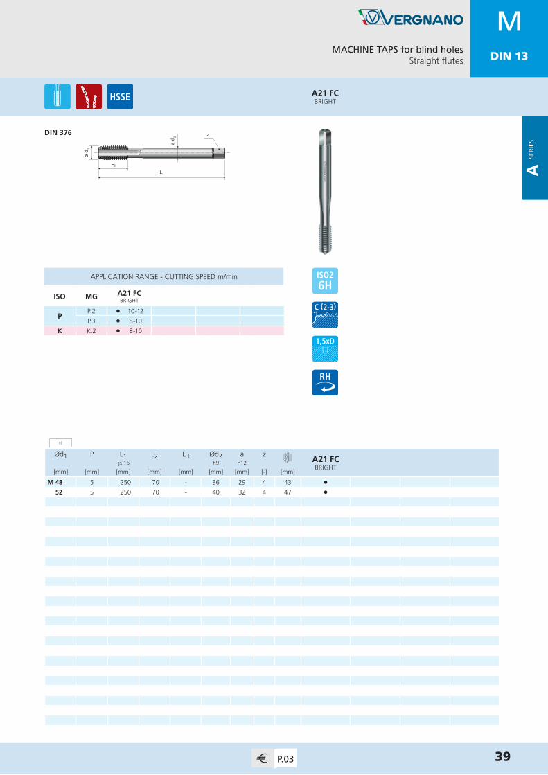
M 48 5 250 70 - 36 29 4 43 •52 5 250 70 - 40 32 4 47 •
APPLICATION RANGE - CUTTING SPEED m/min
ISO MG A21 FCBRIGHT
PP.2 l 10-12
P.3 l 8-10
K K.2 l 8-10
A21 FCBRIGHT
MACHINE TAPS for blind holesStraight flutes
DIN 376
39P.03
MDIN 13
«
A SE
RIE
S

MDIN 13
ø d 2
L1
L2
ø d 1
a
Ød1 P L1 L2 L3 Ød2 a zA22 FCBRIGHT
A22 FCTiN
js 16 h9 h12
[mm] [mm] [mm] [mm] [mm] [mm] [mm] [-] [mm]
M 4 0,7 63 12 - 2,8 2,1 3 3,3 • •5 0,8 70 14 - 3,5 2,7 3 4,2 • •6 1 80 16 - 4,5 3,4 3 5 • •7 1 80 16 - 5,5 4,3 3 6 • •8 1,25 90 18 - 6 4,9 3 6,8 • •9 1,25 90 18 - 7 5,5 3 7,8 • •10 1,5 100 20 - 7 5,5 3 8,5 • •
APPLICATION RANGE - CUTTING SPEED m/min
ISO MG A22 FCBRIGHT
A22 FCTiN
P
P.1 l 20-25
P.2 l 10-12 l 15-20
P.3 l 8-10 l 12-15
K K.2 l 8-10 l 12-15
NN.1 l 20-25
N.5 l 15-20
A22 FCTiN
A22 FCBRIGHT
MACHINE TAPS for blind holesStraight flutes / through shank
DIN 376
40 P.04
MDIN 13
A SE
RIE
S

MDIN 13
ø d 2
L1
L2
L3
ø d 1
a
ø d 1
L1
L2
ø d 2 a
Ød1 P L1 L2 L3 Ød2 a zA43
NITRIDEDA43TiCN
js 16 h9 h12
[mm] [mm] [mm] [mm] [mm] [mm] [mm] [-] [mm]
M 3 0,5 56 10 18 3,5 2,7 3 2,5 • •3,5 0,6 56 11 20 4 3 3 2,9 • •4 0,7 63 12 21 4,5 3,4 3 3,3 • •5 0,8 70 14 24,5 6 4,9 3 4,2 • •6 1 80 16 29 6 4,9 4 5 • •7 1 80 16 29 7 5,5 4 6 • •8 1,25 90 18 33 8 6,2 4 6,8 • •9 1,25 90 18 33 9 7 4 7,8 • •10 1,5 100 20 36 10 8 4 8,5 • •11 1,5 100 22 - 8 6,2 4 9,5 • •12 1,75 110 24 - 9 7 4 10,2 • •14 2 110 25 - 11 9 4 12 • • 16 2 110 28 - 12 9 4 14 • •18 2,5 125 32 - 14 11 4 15,5 • •20 2,5 140 32 - 16 12 4 17,5 • •22 2,5 140 32 - 18 14,5 4 19,5 • •24 3 160 36 - 18 14,5 5 21 • •27 3 160 36 - 20 16 5 24 • •30 3,5 180 40 - 22 18 5 26,5 • •33 3,5 180 40 - 25 20 5 29,5 • •36 4 200 55 - 28 22 5 32 • •
APPLICATION RANGE - CUTTING SPEED m/min
ISO MG A43NITRIDED
A43TiCN
K K.1 l 15-20 l 40-45
N
N.4 l 15-20 l 40-45
N.7 l 15-20 l 40-45
N.9-10 l 20-25 l 45-50
A43TiCN
A43NITRIDED
MACHINE TAPS for blind and through holesStraight flutes / for cast iron
DIN 371≤ M10
DIN 376≥ M11
41P.04
MDIN 13
A SE
RIE
S

MDIN 13
ø d 2
L1
L2
ø d 1
a
Ød1 P L1 L2 L3 Ød2 a zA44
NITRIDEDA44TiCN
js 16 h9 h12
[mm] [mm] [mm] [mm] [mm] [mm] [mm] [-] [mm]
M 4 0,7 63 12 - 2,8 2,1 3 3,3 • •5 0,8 70 14 - 3,5 2,7 3 4,2 • •6 1 80 16 - 4,5 3,4 4 5 • •8 1,25 90 18 - 6 4,9 4 6,8 • •10 1,5 100 20 - 7 5,5 4 8,5 • •
APPLICATION RANGE - CUTTING SPEED m/min
ISO MG A44NITRIDED
A44TiCN
K K.1 l 15-20 l 40-45
N
N.4 l 15-20 l 40-45
N.7 l 15-20 l 40-45
N.9-10 l 20-25 l 45-50
A44TiCN
A44NITRIDED
MACHINE TAPS for blind and through holesStraight flutes / for cast iron / through shank
DIN 376
42 P.04
MDIN 13
A SE
RIE
S

MDIN 13
ø d 2
L1
L2
L3
ø d 1
a
ø d 1
L1
L2
ø d 2 a
Ød1 P L1 L2 L3 Ød2 a zA67
BRIGHTA67TiH1
js 16 h9 h12
[mm] [mm] [mm] [mm] [mm] [mm] [mm] [-] [mm]
M 3 0,5 56 10 18 3,5 2,7 3 2,5 • •4 0,7 63 12 21 4,5 3,4 3 3,3 • •5 0,8 70 14 24,5 6 4,9 3 4,2 • •6 1 80 16 29 6 4,9 3 5 • •8 1,25 90 18 33 8 6,2 3 6,8 • •10 1,5 100 20 36 10 8 3 8,5 • •12 1,75 110 24 - 9 7 3 10,2 • •14 2 110 25 - 11 9 3 12 • •16 2 110 28 - 12 9 3 14 • •18 2,5 125 32 - 14 11 3 15,5 • •20 2,5 140 32 - 16 12 3 17,5 • •
APPLICATION RANGE - CUTTING SPEED m/min
ISO MG A67BRIGHT
A67TiH1
P P.1 l 12-15 l 20-25
N
N.1 l 12-15 l 20-25
N.2 l 10-12 l 15-20
N.5 l 10-12 l 15-20
N.6 l 8-10 l 12-15
A67TiH1
A67BRIGHT
MACHINE TAPS for blind and through holesStraight flutes / interrupted thread / for light alloys
DIN 371≤ M10
DIN 376≥ M12
43P.05
MDIN 13
A SE
RIE
S
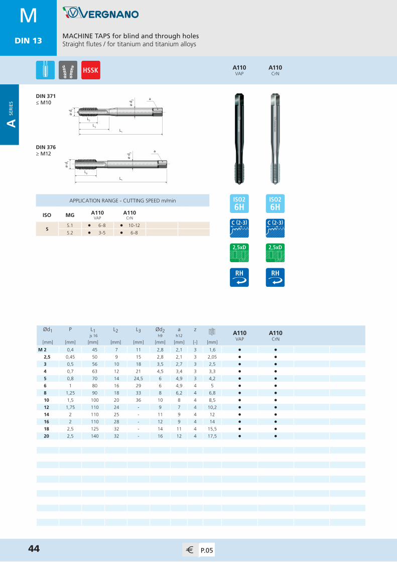
MDIN 13
ø d 2
L1
L2
L3
ø d 1
a
ø d 1
L1
L2
ø d 2 a
Ød1 P L1 L2 L3 Ød2 a zA110
VAPA110
CrN js 16 h9 h12
[mm] [mm] [mm] [mm] [mm] [mm] [mm] [-] [mm]
M 2 0,4 45 7 11 2,8 2,1 3 1,6 • •2,5 0,45 50 9 15 2,8 2,1 3 2,05 • •3 0,5 56 10 18 3,5 2,7 3 2,5 • •4 0,7 63 12 21 4,5 3,4 3 3,3 • •5 0,8 70 14 24,5 6 4,9 3 4,2 • •6 1 80 16 29 6 4,9 4 5 • •8 1,25 90 18 33 8 6,2 4 6,8 • •10 1,5 100 20 36 10 8 4 8,5 • •12 1,75 110 24 - 9 7 4 10,2 • •14 2 110 25 - 11 9 4 12 • •16 2 110 28 - 12 9 4 14 • •18 2,5 125 32 - 14 11 4 15,5 • • 20 2,5 140 32 - 16 12 4 17,5 • •
APPLICATION RANGE - CUTTING SPEED m/min
ISO MG A110VAP
A110CrN
SS.1 l 6-8 l 10-12
S.2 l 3-5 l 6-8
A110CrN
A110VAP
MACHINE TAPS for blind and through holesStraight flutes / for titanium and titanium alloys
DIN 371≤ M10
DIN 376≥ M12
44 P.05
MDIN 13
A SE
RIE
S

MDIN 13
ø d 2
L1
L2
L3
ø d 1
a
ø d 1
L1
L2
ø d 2 a
Ød1 P L1 L2 L3 Ød2 a zA15 SBRIGHT
A15 SVAP
A15 STiN
A15 STiCN
js 16 h9 h12
[mm] [mm] [mm] [mm] [mm] [mm] [mm] [-] [mm]
M 2 0,4 45 7 11 2,8 2,1 2 1,6 • • • •2,2 0,45 45 8 13 2,8 2,1 2 1,75 • • •2,3 0,4 45 8 13 2,8 2,1 2 1,9 • • •2,5 0,45 50 9 15 2,8 2,1 3 2,05 • • • •2,6 0,45 50 9 15 2,8 2,1 3 2,1 • • •3 0,5 56 10 18 3,5 2,7 3 2,5 • • • •3,5 0,6 56 11 20 4 3 3 2,9 • • • •4 0,7 63 12 21 4,5 3,4 3 3,3 • • • •5 0,8 70 14 24,5 6 4,9 3 4,2 • • • •6 1 80 16 29 6 4,9 3 5 • • • •7 1 80 16 29 7 5,5 3 6 • • • •8 1,25 90 18 33 8 6,2 3 6,8 • • • • 9 1,25 90 18 33 9 7 3 7,8 • • • •10 1,5 100 20 36 10 8 3 8,5 • • • •11 1,5 100 22 - 8 6,2 3 9,5 • • •12 1,75 110 24 - 9 7 4 10,2 • • • •14 2 110 25 - 11 9 4 12 • • • •16 2 110 28 - 12 9 4 14 • • • •18 2,5 125 32 - 14 11 4 15,5 • • • •20 2,5 140 32 - 16 12 4 17,5 • • • •22 2,5 140 32 - 18 14,5 4 19,5 • • • •24 3 160 36 - 18 14,5 4 21 • • • •27 3 160 36 - 20 16 4 24 • • • • 30 3,5 180 40 - 22 18 4 26,5 • • • •33 3,5 180 40 - 25 20 5 29,5 • •36 4 200 55 - 28 22 5 32 • •
APPLICATION RANGE - CUTTING SPEED m/min
ISO MG A15 SBRIGHT
A15 SVAP
A15 STiN
A15 STiCN
P
P.2 l 20-25 l 20-25 l 30-35 l 30-35
P.3 l 15-20 l 15-20 l 25-30 l 25-30
P.4 l 12-15 l 12-15 l 20-25 l 20-25
P.5 l 10-15 l 10-15
P.7 l 10-15 l 10-15
M M.1 l 10-15 l 10-15
K K.2 l 15-20 l 15-20 l 25-30 l 25-30
NN.2-3 l 20-25 l 20-25 l 30-35 l 30-35
N.6 l 15-18 l 15-18 l 25-30 l 25-30
A15 STiCN
A15 STiN
A15 SVAP
A15 SBRIGHT
MACHINE TAPS for through holesStraight flutes with spiral point
DIN 371≤ M10
DIN 376≥ M11
45P.06
MDIN 13
»
A SE
RIE
S

MDIN 13
Ød1 P L1 L2 L3 Ød2 a zA15 SBRIGHT
js 16 h9 h12
[mm] [mm] [mm] [mm] [mm] [mm] [mm] [-] [mm]
M 39 4 200 60 - 32 24 5 35 •42 4,5 200 60 - 32 24 5 37,5 •45 4,5 220 65 - 36 29 5 40,5 •48 5 250 70 - 36 29 5 43 •52 5 250 70 - 40 32 5 47 •
MACHINE TAPS for through holesStraight flutes with spiral point
DIN 376
46 P.06
ø d 1
L1
L2
ø d 2 a
A15 SBRIGHT
APPLICATION RANGE - CUTTING SPEED m/min
ISO MG A15 SBRIGHT
P
P.2 l 20-25
P.3 l 15-20
P.4 l 12-15
K K.2 l 15-20
NN.2-3 l 20-25
N.6 l 15-18
MDIN 13
«
A SE
RIE
S

MDIN 13
ø d 2
L1
L2
L3
ø d 1
a
ø d 1
L1
L2
ø d 2 a
Ød1 P L1 L2 L3 Ød2 a zA15 S 4H
BRIGHTA15 S 4H
TiN js 16 h9 h12
[mm] [mm] [mm] [mm] [mm] [mm] [mm] [-] [mm]
M 2 0,4 45 7 11 2,8 2,1 2 1,6 • •2,5 0,45 50 9 15 2,8 2,1 3 2,05 • •3 0,5 56 10 18 3,5 2,7 3 2,5 • •4 0,7 63 12 21 4,5 3,4 3 3,3 • •5 0,8 70 14 24,5 6 4,9 3 4,2 • •6 1 80 16 29 6 4,9 3 5 • •8 1,25 90 18 33 8 6,2 3 6,8 • •10 1,5 100 20 36 10 8 3 8,5 • •12 1,75 110 24 - 9 7 4 10,2 • •14 2 110 25 - 11 9 4 12 • •16 2 110 28 - 12 9 4 14 • •
A15 S 4HTiN
A15 S 4H BRIGHT
MACHINE TAPS for through holesStraight flutes with spiral point
DIN 371≤ M10
DIN 376≥ M12
47P.06
APPLICATION RANGE - CUTTING SPEED m/min
ISO MG A15 S 4H BRIGHT
A15 S 4HTiN
P
P.2 l 20-25 l 30-35
P.3 l 15-20 l 25-30
P.4 l 12-15 l 20-25
P.5 l 10-15
P.7 l 10-15
M M.1 l 10-15
K K.2 l 15-20 l 25-30
NN.2-3 l 20-25 l 30-35
N.6 l 15-18 l 25-30
MDIN 13
A SE
RIE
S

MDIN 13
ø d 2
L1
L2
L3
ø d 1
a
ø d 1
L1
L2
ø d 2 a
Ød1 P L1 L2 L3 Ød2 a zA15 S 6G
BRIGHTA15 S 6G
TiN js 16 h9 h12
[mm] [mm] [mm] [mm] [mm] [mm] [mm] [-] [mm]
M 2 0,4 45 7 11 2,8 2,1 2 1,6 • •2,5 0,45 50 9 15 2,8 2,1 3 2,05 • •3 0,5 56 10 18 3,5 2,7 3 2,5 • •4 0,7 63 12 21 4,5 3,4 3 3,3 • •5 0,8 70 14 24,5 6 4,9 3 4,2 • •6 1 80 16 29 6 4,9 3 5 • •8 1,25 90 18 33 8 6,2 3 6,8 • •10 1,5 100 20 36 10 8 3 8,5 • •12 1,75 110 24 - 9 7 4 10,2 • •14 2 110 25 - 11 9 4 12 • •16 2 110 28 - 12 9 4 14 • •
A15 S 6GTiN
A15 S 6G BRIGHT
MACHINE TAPS for through holesStraight flutes with spiral point
DIN 371≤ M10
DIN 376≥ M12
48 P.07
APPLICATION RANGE - CUTTING SPEED m/min
ISO MG A15 S 6G BRIGHT
A15 S 6GTiN
P
P.2 l 20-25 l 30-35
P.3 l 15-20 l 25-30
P.4 l 12-15 l 20-25
P.5 l 10-15
P.7 l 10-15
M M.1 l 10-15
K K.2 l 15-20 l 25-30
NN.2-3 l 20-25 l 30-35
N.6 l 15-18 l 25-30
MDIN 13
A SE
RIE
S

MDIN 13
ø d 2
L1
L2
L3
ø d 1
a
ø d 1
L1
L2
ø d 2 a
Ød1 P L1 L2 L3 Ød2 a zA15 S 7G
BRIGHTA15 S 7G
TiN js 16 h9 h12
[mm] [mm] [mm] [mm] [mm] [mm] [mm] [-] [mm]
M 3 0,5 56 10 18 3,5 2,7 3 2,5 • •4 0,7 63 12 21 4,5 3,4 3 3,3 • •5 0,8 70 14 24,5 6 4,9 3 4,2 • •6 1 80 16 29 6 4,9 3 5 • •8 1,25 90 18 33 8 6,2 3 6,8 • •10 1,5 100 20 36 10 8 3 8,5 • •12 1,75 110 24 - 9 7 4 10,2 • •14 2 110 25 - 11 9 4 12 • •16 2 110 28 - 12 9 4 14 • •
A15 S 7GTiN
A15 S 7G BRIGHT
MACHINE TAPS for through holesStraight flutes with spiral point
DIN 371≤ M10
DIN 376≥ M12
49P.07
APPLICATION RANGE - CUTTING SPEED m/min
ISO MG A15 S 7G BRIGHT
A15 S 7GTiN
P
P.2 l 20-25 l 30-35
P.3 l 15-20 l 25-30
P.4 l 12-15 l 20-25
P.5 l 10-15
P.7 l 10-15
M M.1 l 10-15
K K.2 l 15-20 l 25-30
NN.2-3 l 20-25 l 30-35
N.6 l 15-18 l 25-30
MDIN 13
A SE
RIE
S
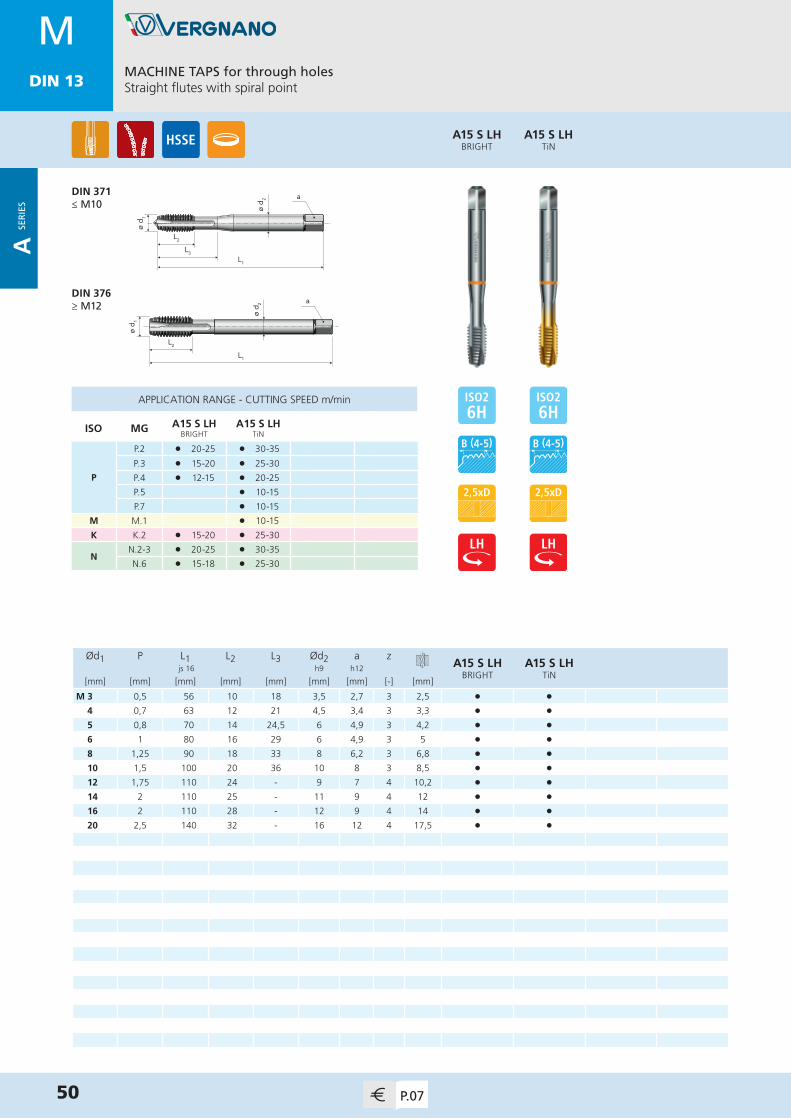
MDIN 13
ø d 2
L1
L2
L3
ø d 1
a
ø d 1
L1
L2
ø d 2 a
Ød1 P L1 L2 L3 Ød2 a zA15 S LH
BRIGHTA15 S LH
TiN js 16 h9 h12
[mm] [mm] [mm] [mm] [mm] [mm] [mm] [-] [mm]
M 3 0,5 56 10 18 3,5 2,7 3 2,5 • •4 0,7 63 12 21 4,5 3,4 3 3,3 • •5 0,8 70 14 24,5 6 4,9 3 4,2 • •6 1 80 16 29 6 4,9 3 5 • •8 1,25 90 18 33 8 6,2 3 6,8 • •10 1,5 100 20 36 10 8 3 8,5 • •12 1,75 110 24 - 9 7 4 10,2 • •14 2 110 25 - 11 9 4 12 • •16 2 110 28 - 12 9 4 14 • •20 2,5 140 32 - 16 12 4 17,5 • •
A15 S LHTiN
A15 S LH BRIGHT
MACHINE TAPS for through holesStraight flutes with spiral point
DIN 371≤ M10
DIN 376≥ M12
50 P.07
APPLICATION RANGE - CUTTING SPEED m/min
ISO MG A15 S LH BRIGHT
A15 S LHTiN
P
P.2 l 20-25 l 30-35
P.3 l 15-20 l 25-30
P.4 l 12-15 l 20-25
P.5 l 10-15
P.7 l 10-15
M M.1 l 10-15
K K.2 l 15-20 l 25-30
NN.2-3 l 20-25 l 30-35
N.6 l 15-18 l 25-30
MDIN 13
A SE
RIE
S

MDIN 13
ø d 2
L1
L2
ø d 1
a
Ød1 P L1 L2 L3 Ød2 a zA16 SBRIGHT
A16 STiN
js 16 h9 h12
[mm] [mm] [mm] [mm] [mm] [mm] [mm] [-] [mm]
M 4 0,7 63 12 - 2,8 2,1 3 3,3 • •5 0,8 70 14 - 3,5 2,7 3 4,2 • •6 1 80 16 - 4,5 3,4 3 5 • •7 1 80 16 - 5,5 4,3 3 6 • •8 1,25 90 18 - 6 4,9 3 6,8 • •9 1,25 90 18 - 7 5,5 3 7,8 • •10 1,5 100 20 - 7 5,5 3 8,5 • •
A16 STiN
A16 SBRIGHT
MACHINE TAPS for through holesStraight flutes with spiral point / through shank
DIN 376
51P.07
APPLICATION RANGE - CUTTING SPEED m/min
ISO MG A16 SBRIGHT
A16 STiN
P
P.2 l 20-25 l 30-35
P.3 l 15-20 l 25-30
P.4 l 12-15 l 20-25
P.5 l 10-15
P.7 l 10-15
M M.1 l 10-15
K K.2 l 15-20 l 25-30
NN.2-3 l 20-25 l 30-35
N.6 l 15-18 l 25-30
MDIN 13
A SE
RIE
S

MDIN 13
ø d 2
L1
L2
L3
ø d 1
a
ø d 1
L1
L2
ø d 2 a
Ød1 P L1 L2 L3 Ød2 a zA15 AZBRIGHT
A15 AZTiH1
js 16 h9 h12
[mm] [mm] [mm] [mm] [mm] [mm] [mm] [-] [mm]
M 3 0,5 56 10 18 3,5 2,7 3 2,5 • •4 0,7 63 12 21 4,5 3,4 3 3,3 • •5 0,8 70 14 24,5 6 4,9 3 4,2 • •6 1 80 16 29 6 4,9 3 5 • •8 1,25 90 18 33 8 6,2 3 6,8 • •10 1,5 100 20 36 10 8 3 8,5 • •12 1,75 110 24 - 9 7 3 10,2 • •14 2 110 25 - 11 9 3 12 • •16 2 110 28 - 12 9 3 14 • •
APPLICATION RANGE - CUTTING SPEED m/min
ISO MG A15 AZBRIGHT
A15 AZTiH1
P P.1 l 18-20 l 30-35
N
N.1 l 18-20 l 30-40
N.2 l 15-18 l 30-40
N.5 l 15-18 l 30-35
N.6 l 12-15 l 30-35
A15 AZTiH1
A15 AZBRIGHT
MACHINE TAPS for through holesStraight flutes with spiral point / interrupted thread
DIN 371≤ M10
DIN 376≥ M12
52 P.08
MDIN 13
A SE
RIE
S

MDIN 13
L1
L2
L3
ø d 1
ø d 2 a
ø d 1
L1
L2
ø d 2 a
Ød1 P L1 L2 L3 Ød2 a zA15 LBRIGHT
A15 LTiN
js 16 h9 h12
[mm] [mm] [mm] [mm] [mm] [mm] [mm] [-] [mm]
M 3 0,5 112 10 18 3,5 2,7 3 2,5 • •4 0,7 112 12 21 4,5 3,4 3 3,3 • •5 0,8 125 14 24,5 6 4,9 3 4,2 • •6 1 125 16 29 6 4,9 3 5 • •8 1,25 140 18 33 8 6,2 3 6,8 • •10 1,5 160 20 36 10 8 3 8,5 • •12 1,75 180 24 - 9 7 3 10,2 • •16 2 200 28 - 12 9 3 14 • •20 2,5 225 32 - 16 12 4 17,5 • •
APPLICATION RANGE - CUTTING SPEED m/min
ISO MG A15 LBRIGHT
A15 LTiN
P
P.1 l 18-20 l 30-35
P.2 l 15-18 l 25-30
P.3 l 12-15 l 20-25
N
N.1 l 18-20
N.2 l 15-18 l 25-30
N.5 l 15-18
N.6 l 12-15 l 20-25
A15 LTiN
A15 LBRIGHT
MACHINE TAPS for through holesStraight flutes with spiral point / long shank
NORM VERGNANO≤ M10
NORM VERGNANO≥ M12
53P.08
MDIN 13
A SE
RIE
S

MDIN 13
ø d 2
L1
L2
L3
ø d 1
a
ø d 1
L1
L2
ø d 2 a
Ød1 P L1 L2 L3 Ød2 a zA150
VAPA150TiX2
js 16 h9 h12
[mm] [mm] [mm] [mm] [mm] [mm] [mm] [-] [mm]
M 3 0,5 56 10 18 3,5 2,7 3 2,5 • •3,5 0,6 56 11 16 4 3 3 2,9 • •4 0,7 63 12 21 4,5 3,4 3 3,3 • •5 0,8 70 14 24,5 6 4,9 3 4,2 • •6 1 80 16 29 6 4,9 3 5 • •8 1,25 90 18 33 8 6,2 3 6,8 • •10 1,5 100 20 36 10 8 3 8,5 • •12 1,75 110 24 - 9 7 3 10,2 • •14 2 110 25 - 11 9 3 12 • •16 2 110 28 - 12 9 3 14 • •18 2,5 125 32 - 14 11 4 15,5 • •20 2,5 140 32 - 16 12 4 17,5 • •
APPLICATION RANGE - CUTTING SPEED m/min
ISO MG A150VAP
A150TiX2
P P.7 l 10-12 l 18-20
MM.1 l 10-12 l 18-20
M.2 l 8-10 l 10-20
A150TiX2
A150VAP
MACHINE TAPS for through holesStraight flutes with spiral point / for stainless steel
DIN 371≤ M10
DIN 376≥ M12
54 P.08
MDIN 13
A SE
RIE
S

MDIN 13
ø d 2
L1
L2
L3
ø d 1
a
ø d 1
L1
L2
ø d 2 a
Ød1 P L1 L2 L3 Ød2 a zA29
BRIGHTA29VAP
A29TiN
js 16 h9 h12
[mm] [mm] [mm] [mm] [mm] [mm] [mm] [-] [mm]
M 2 0,4 45 7 11 2,8 2,1 3 1,6 • • •2,2 0,45 45 8 13 2,8 2,1 3 1,75 •2,3 0,4 45 8 13 2,8 2,1 3 1,9 •2,5 0,45 50 9 15 2,8 2,1 3 2,05 • • •2,6 0,45 50 9 15 2,8 2,1 3 2,1 •3 0,5 56 10 18 3,5 2,7 3 2,5 • • •3,5 0,6 56 11 20 4 3 3 2,9 • • •4 0,7 63 12 21 4,5 3,4 3 3,3 • • •4,5 0,75 70 14 24,5 6 4,9 3 3,7 •5 0,8 70 14 24,5 6 4,9 3 4,2 • • •6 1 80 16 29 6 4,9 3 5 • • •7 1 80 16 29 7 5,5 3 6 • • •8 1,25 90 18 33 8 6,2 3 6,8 • • •9 1,25 90 18 33 9 7 3 7,8 • • •10 1,5 100 20 36 10 8 3 8,5 • • •11 1,5 100 22 - 8 6,2 3 9,5 •12 1,75 110 24 - 9 7 3 10,2 • • • 14 2 110 25 - 11 9 3 12 • • •16 2 110 28 - 12 9 3 14 • • •18 2,5 125 32 - 14 11 3 15,5 • • •20 2,5 140 32 - 16 12 4 17,5 • • •22 2,5 140 32 - 18 14,5 4 19,5 • • •24 3 160 36 - 18 14,5 4 21 • • •27 3 160 36 - 20 16 4 24 • • •30 3,5 180 40 - 22 18 4 26,5 • • •33 3,5 180 40 - 25 20 5 29,5 • • •
APPLICATION RANGE - CUTTING SPEED m/min
ISO MG A29BRIGHT
A29VAP
A29TiN
P
P.1 l 18-20 l 18-20 l 30-35
P.2 l 15-18 l 15-18 l 25-30
P.3 l 12-15 l 12-15 l 20-25
P.4 l 10-12 l 10-12 l 15-20
P.5 l 5-10
K K.2 l 12-15 l 12-15 l 20-25
N
N.1 l 18-20 l 18-20
N.2-3 l 15-18 l 15-18 l 25-30
N.5 l 15-18 l 15-18
N.6 l 12-15 l 12-15 l 20-25
A29TiN
A29VAP
A29BRIGHT
MACHINE TAPS for blind holes15° spiral flutes
DIN 371≤ M10
DIN 376≥ M11
55P.09
MDIN 13
A SE
RIE
S
»

MDIN 13
Ød1 P L1 L2 L3 Ød2 a zA29
BRIGHT js 16 h9 h12
[mm] [mm] [mm] [mm] [mm] [mm] [mm] [-] [mm]
M 36 4 200 56 - 28 22 5 32 •39 4 200 60 - 32 24 5 35 •42 4,5 200 60 - 32 24 5 37,5 •45 4,5 220 65 - 36 29 5 40,5 •48 5 250 70 - 36 29 5 43 •52 5 250 70 - 40 32 5 47 •
MACHINE TAPS for blind holes15° spiral flutes
56 P.09
ø d 1
L1
L2
ø d 2 a
APPLICATION RANGE - CUTTING SPEED m/min
ISO MG A29BRIGHT
P
P.1 l 18-20
P.2 l 15-18
P.3 l 12-15
P.4 l 10-12
K K.2 l 12-15
N
N.1 l 18-20
N.2-3 l 15-18
N.5 l 15-18
N.6 l 12-15
DIN 376
A29BRIGHT
MDIN 13
«
A SE
RIE
S

MDIN 13
ø d 2
L1
L2
L3
ø d 1
a
ø d 1
L1
L2
ø d 2 a
Ød1 P L1 L2 L3 Ød2 a zA29 6G BRIGHT
A29 6GTiN
js 16 h9 h12
[mm] [mm] [mm] [mm] [mm] [mm] [mm] [-] [mm]
M 2 0,4 45 7 11 2,8 2,1 3 1,6 • •2,5 0,45 50 9 15 2,8 2,1 3 2,05 • •3 0,5 56 10 18 3,5 2,7 3 2,5 • •4 0,7 63 12 21 4,5 3,4 3 3,3 • •5 0,8 70 14 24,5 6 4,9 3 4,2 • •6 1 80 16 29 6 4,9 3 5 • •8 1,25 90 18 33 8 6,2 3 6,8 • •10 1,5 100 20 36 10 8 3 8,5 • •12 1,75 110 24 - 9 7 3 10,2 • •14 2 110 25 - 11 9 3 12 • •
A29 6GTiN
A29 6G BRIGHT
MACHINE TAPS for blind holes15° spiral flutes
DIN 371≤ M10
DIN 376≥ M12
57P.09
APPLICATION RANGE - CUTTING SPEED m/min
ISO MG A29 6G BRIGHT
A29 6GTiN
P
P.1 l 18-20 l 30-35
P.2 l 15-18 l 25-30
P.3 l 12-15 l 20-25
P.4 l 10-12 l 15-20
P.5 l 5-10
K K.2 l 12-15 l 20-25
N
N.1 l 18-20
N.2-3 l 15-18 l 25-30
N.5 l 15-18
N.6 l 12-15 l 20-25
MDIN 13
A SE
RIE
S

MDIN 13
A29 DIN 376 TiN
A29 DIN 376 BRIGHT
MACHINE TAPS for blind holes15° spiral flutes / through shank
58 P.10
ø d 2
L1
L2
ø d 1
a
Ød1 P L1 L2 L3 Ød2 a zA29 DIN 376
BRIGHTA29 DIN 376
TiN js 16 h9 h12
[mm] [mm] [mm] [mm] [mm] [mm] [mm] [-] [mm]
M 5 0,8 70 14 - 3,5 2,7 3 4,2 • •6 1 80 16 - 4,5 3,4 3 5 • •8 1,25 90 18 - 6 4,9 3 6,8 • •10 1,5 100 20 - 7 5,5 3 8,5 • •
DIN 376
APPLICATION RANGE - CUTTING SPEED m/min
ISO MG A29 DIN 376 BRIGHT
A29 DIN 376 TiN
P
P.1 l 18-20 l 30-35
P.2 l 15-18 l 25-30
P.3 l 12-15 l 20-25
P.4 l 10-12 l 15-20
P.5 l 5-10
K K.2 l 12-15 l 20-25
N
N.1 l 18-20
N.2-3 l 15-18 l 25-30
N.5 l 15-18
N.6 l 12-15 l 20-25
MDIN 13
A SE
RIE
S

MDIN 13
A29 LTiN
A29 LBRIGHT
MACHINE TAPS for blind holes15° spiral flutes / long shank
59P.10
MDIN 13
A SE
RIE
S
Ød1 P L1 L2 L3 Ød2 a zA29 LBRIGHT
A29 LTiN
js 16 h9 h12
[mm] [mm] [mm] [mm] [mm] [mm] [mm] [-] [mm]
M 4 0,7 112 12 21 4,5 3,4 3 3,3 • •5 0,8 125 14 24,5 6 4,9 3 4,2 • •6 1 125 16 29 6 4,9 3 5 • •8 1,25 140 18 33 8 6,2 3 6,8 • •10 1,5 160 20 36 10 8 3 8,5 • •12 1,75 180 24 - 9 7 3 10,2 • •
NORM VERGNANO≤ M10
NORM VERGNANO≥ M12
ø d 2
L1
L2
L3
ø d 1
a
ø d 1
L1
L2
ø d 2 a
APPLICATION RANGE - CUTTING SPEED m/min
ISO MG A29 LBRIGHT
A29 LTiN
P
P.1 l 18-20 l 30-35
P.2 l 15-18 l 25-30
P.3 l 12-15 l 20-25
P.4 l 10-12 l 15-20
P.5 l 5-10
K K.2 l 12-15 l 20-25
N
N.1 l 18-20
N.2-3 l 15-18 l 25-30
N.5 l 15-18
N.6 l 12-15 l 20-25

MDIN 13
ø d 2
L1
L2
L3
ø d 1
a
APPLICATION RANGE - CUTTING SPEED m/min
ISO MG A70 SBRIGHT
A70 SVAP
A70 STiN
A70 STiCN
P
P.2 l 15-20 l 15-20 l 25-30 l 25-30
P.3 l 12-15 l 12-15 l 20-25 l 20-25
P.4 l 10-12 l 10-12 l 15-20 l 15-20
P.5 l 5-10 l 5-10
P.7 l 8-10 l 8-10
M M.1 l 8-10 l 8-10
K K2 l 12-15 l 12-15 l 20-25 l 20-25
NN.3 l 15-18 l 15-18 l 25-30 l 25-30
N.6 l 15-18 l 15-18 l 25-30 l 25-30
A70 STiCN
A70 STiN
A70 SVAP
A70 SBRIGHT
MACHINE TAPS for blind holes40° spiral flutes / back tapered
DIN 371≤ M10
DIN 376≥ M11
60 P.10
Ød1 P L1 L2 L3 Ød2 a zA70 SBRIGHT
A70 SVAP
A70 STiN
A70 STiCN
js 16 h9 h12
[mm] [mm] [mm] [mm] [mm] [mm] [mm] [-] [mm]
M 2 0,4 45 6 12 2,8 2,1 3 1,6 • • • •2,5 0,45 50 6,5 15 2,8 2,1 3 2,05 • • • •3 0,5 56 7 15 3,5 2,7 3 2,5 • • • •3,5 0,6 56 8 18,5 4 3 3 2,9 • • • •4 0,7 63 8,5 21 4,5 3,4 3 3,3 • • • •5 0,8 70 10 24,5 6 4,9 3 4,2 • • • •6 1 80 12 29 6 4,9 3 5 • • • •7 1 80 12 29 7 5,5 3 6 • • • •8 1,25 90 15 33 8 6,2 3 6,8 • • • •9 1,25 90 15 33 9 7 3 7,8 • • • •10 1,5 100 17,5 38 10 8 3 8,5 • • • •11 1,5 100 17,5 - 8 6,2 3 9,5 • • • • 12 1,75 110 18 - 9 7 4 10,2 • • • •14 2 110 20,5 - 11 9 4 12 • • • •16 2 110 20,5 - 12 9 4 14 • • • •18 2,5 125 25,5 - 14 11 4 15,5 • • • •20 2,5 140 29,5 - 16 12 4 17,5 • • • •22 2,5 140 29,5 - 18 14,5 4 19,5 • • • •24 3 160 35,5 - 18 14,5 4 21 • • • •27 3 160 37,5 - 20 16 5 24 • • • •30 3,5 180 42 - 22 18 5 26,5 • • • •33 3,5 180 43,5 - 25 20 5 29,5 • • •36 4 200 47 - 28 22 5 32 • • •42 4,5 200 55 - 32 24 6 37,5 •48 5 250 59,5 - 36 29 6 43 •52 5 250 59,5 - 40 32 6 47 •
MDIN 13
A SE
RIE
S

MDIN 13
ø d 2
L1
L2
L3
ø d 1
a
Ød1 P L1 L2 L3 Ød2 a zA70 S 4H
BRIGHTA70 S 4H
TiN js 16 h9 h12
[mm] [mm] [mm] [mm] [mm] [mm] [mm] [-] [mm]
M 2 0,4 45 6 12 2,8 2,1 3 1,6 • •2,5 0,45 50 6,5 15 2,8 2,1 3 2,05 • •3 0,5 56 7 15 3,5 2,7 3 2,5 • •4 0,7 63 8,5 21 4,5 3,4 3 3,3 • •5 0,8 70 10 24,5 6 4,9 3 4,2 • •6 1 80 12 29 6 4,9 3 5 • •8 1,25 90 15 33 8 6,2 3 6,8 • •10 1,5 100 17,5 38 10 8 3 8,5 • •12 1,75 110 18 - 9 7 4 10,2 • •
A70 S 4HTiN
A70 S 4HBRIGHT
MACHINE TAPS for blind holes40° spiral flutes / back tapered
DIN 371≤ M10
DIN 376≥ M12
61P.11
APPLICATION RANGE - CUTTING SPEED m/min
ISO MG A70 S 4HBRIGHT
A70 S 4HTiN
P
P.2 l 15-20 l 25-30
P.3 l 12-15 l 20-25
P.4 l 10-12 l 15-20
P.5 l 5-10
P.7 l 8-10
M M.1 l 8-10
K K2 l 12-15 l 20-25
NN.3 l 15-18 l 25-30
N.6 l 15-18 l 25-30
MDIN 13
A SE
RIE
S

MDIN 13
ø d 2
L1
L2
L3
ø d 1
a
Ød1 P L1 L2 L3 Ød2 a zA70 S 6G
BRIGHTA70 S 6G
TiN js 16 h9 h12
[mm] [mm] [mm] [mm] [mm] [mm] [mm] [-] [mm]
M 3 0,5 56 7 15 3,5 2,7 3 2,5 • •4 0,7 63 8,5 21 4,5 3,4 3 3,3 • •5 0,8 70 10 24,5 6 4,9 3 4,2 • •6 1 80 12 29 6 4,9 3 5 • •8 1,25 90 15 33 8 6,2 3 6,8 • •10 1,5 100 17,5 38 10 8 3 8,5 • •12 1,75 110 18 - 9 7 4 10,2 • •14 2 110 20,5 - 11 9 4 12 • •16 2 110 20,5 - 12 9 4 14 • •
APPLICATION RANGE - CUTTING SPEED m/min
ISO MG A70 S 6GBRIGHT
A70 S 6GTiN
P
P.2 l 15-20 l 25-30
P.3 l 12-15 l 20-25
P.4 l 10-12 l 15-20
P.5 l 5-10
P.7 l 8-10
M M.1 l 8-10
K K2 l 12-15 l 20-25
NN.3 l 15-18 l 25-30
N.6 l 15-18 l 25-30
A70 S 6GTiN
A70 S 6GBRIGHT
MACHINE TAPS for blind holes40° spiral flutes / back tapered
DIN 371≤ M10
DIN 376≥ M12
62 P.11
MDIN 13
A SE
RIE
S

MDIN 13
ø d 2
L1
L2
L3
ø d 1
a
Ød1 P L1 L2 L3 Ød2 a zA70 S 7G
BRIGHTA70 S 7G
TiN js 16 h9 h12
[mm] [mm] [mm] [mm] [mm] [mm] [mm] [-] [mm]
M 3 0,5 56 7 15 3,5 2,7 3 2,5 • •4 0,7 63 8,5 21 4,5 3,4 3 3,3 • •5 0,8 70 10 24,5 6 4,9 3 4,2 • •6 1 80 12 29 6 4,9 3 5 • •8 1,25 90 15 33 8 6,2 3 6,8 • •10 1,5 100 17,5 38 10 8 3 8,5 • •12 1,75 110 18 - 9 7 4 10,2 • •14 2 110 20,5 - 11 9 4 12 • •16 2 110 20,5 - 12 9 4 14 • •
A70 S 7GTiN
A70 S 7GBRIGHT
MACHINE TAPS for blind holes40° spiral flutes / back tapered
DIN 371≤ M10
DIN 376≥ M12
63P.11
APPLICATION RANGE - CUTTING SPEED m/min
ISO MG A70 S 7GBRIGHT
A70 S 7GTiN
P
P.2 l 15-20 l 25-30
P.3 l 12-15 l 20-25
P.4 l 10-12 l 15-20
P.5 l 5-10
P.7 l 8-10
M M.1 l 8-10
K K2 l 12-15 l 20-25
NN.3 l 15-18 l 25-30
N.6 l 15-18 l 25-30
MDIN 13
A SE
RIE
S
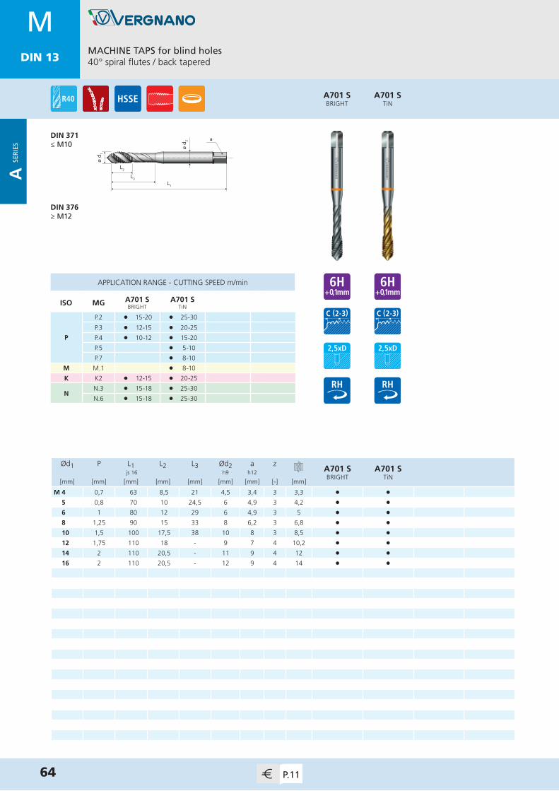
MDIN 13
ø d 2
L1
L2
L3
ø d 1
a
Ød1 P L1 L2 L3 Ød2 a zA701 SBRIGHT
A701 STiN
js 16 h9 h12
[mm] [mm] [mm] [mm] [mm] [mm] [mm] [-] [mm]
M 4 0,7 63 8,5 21 4,5 3,4 3 3,3 • •5 0,8 70 10 24,5 6 4,9 3 4,2 • •6 1 80 12 29 6 4,9 3 5 • •8 1,25 90 15 33 8 6,2 3 6,8 • •10 1,5 100 17,5 38 10 8 3 8,5 • •12 1,75 110 18 - 9 7 4 10,2 • •14 2 110 20,5 - 11 9 4 12 • •16 2 110 20,5 - 12 9 4 14 • •
APPLICATION RANGE - CUTTING SPEED m/min
ISO MG A701 SBRIGHT
A701 STiN
P
P.2 l 15-20 l 25-30
P.3 l 12-15 l 20-25
P.4 l 10-12 l 15-20
P.5 l 5-10
P.7 l 8-10
M M.1 l 8-10
K K2 l 12-15 l 20-25
NN.3 l 15-18 l 25-30
N.6 l 15-18 l 25-30
A701 STiN
A701 SBRIGHT
MACHINE TAPS for blind holes40° spiral flutes / back tapered
DIN 371≤ M10
DIN 376≥ M12
64 P.11
MDIN 13
A SE
RIE
S
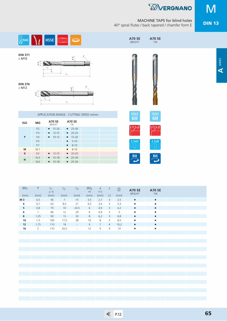
MDIN 13
ø d 2
L1
L2
L3
ø d 1
a
ø d 1
L2
ø d 2 a
L1
Ød1 P L1 L2 L3 Ød2 a zA70 SEBRIGHT
A70 SETiN
js 16 h9 h12
[mm] [mm] [mm] [mm] [mm] [mm] [mm] [-] [mm]
M 3 0,5 56 7 15 3,5 2,7 3 2,5 • •4 0,7 63 8,5 21 4,5 3,4 3 3,3 • •5 0,8 70 10 24,5 6 4,9 3 4,2 • •6 1 80 12 29 6 4,9 3 5 • •8 1,25 90 15 33 8 6,2 3 6,8 • •10 1,5 100 17,5 38 10 8 3 8,5 • •12 1,75 110 18 - 9 7 4 10,2 • •16 2 110 20,5 - 12 9 4 14 • •
A70 SETiN
A70 SEBRIGHT
MACHINE TAPS for blind holes40° spiral flutes / back tapered / chamfer form E
DIN 371≤ M10
DIN 376≥ M12
65P.12
APPLICATION RANGE - CUTTING SPEED m/min
ISO MG A70 SEBRIGHT
A70 SETiN
P
P.2 l 15-20 l 25-30
P.3 l 12-15 l 20-25
P.4 l 10-12 l 15-20
P.5 l 5-10
P.7 l 8-10
M M.1 l 8-10
K K2 l 12-15 l 20-25
NN.3 l 15-18 l 25-30
N.6 l 15-18 l 25-30
MDIN 13
A SE
RIE
S

MDIN 13
ø d 2
L1
L2
L3
ø d 1
a
ø d 1
L1
L2
ø d 2 a
Ød1 P L1 L2 L3 Ød2 a zA70 S LH
BRIGHTA70 S LH
TiN js 16 h9 h12
[mm] [mm] [mm] [mm] [mm] [mm] [mm] [-] [mm]
M 3 0,5 56 7 15 3,5 2,7 3 2,5 • •4 0,7 63 8,5 21 4,5 3,4 3 3,3 • •5 0,8 70 10 24,5 6 4,9 3 4,2 • •6 1 80 12 29 6 4,9 3 5 • •8 1,25 90 15 33 8 6,2 3 6,8 • •10 1,5 100 17,5 38 10 8 3 8,5 • •12 1,75 110 18 - 9 7 4 10,2 • •14 2 110 20,5 - 11 9 4 12 • •16 2 110 20,5 - 12 9 4 14 • •20 2,5 140 29,5 - 16 12 4 17,5 • •22 2,5 140 29,5 - 18 14,5 4 19,5 • •24 3 160 35,5 - 18 14,5 4 21 • •27 3 160 37,5 - 20 16 5 24 • •30 3,5 180 42 - 22 18 5 26,5 • •
A70 S LHTiN
A70 S LHBRIGHT
MACHINE TAPS for blind holes40° spiral flutes / back tapered
DIN 371≤ M10
DIN 376≥ M12
66 P.12
APPLICATION RANGE - CUTTING SPEED m/min
ISO MG A70 S LHBRIGHT
A70 S LHTiN
P
P.2 l 15-20 l 25-30
P.3 l 12-15 l 20-25
P.4 l 10-12 l 15-20
P.5 l 5-10
P.7 l 8-10
M M.1 l 8-10
K K2 l 12-15 l 20-25
NN.3 l 15-18 l 25-30
N.6 l 15-18 l 25-30
MDIN 13
A SE
RIE
S
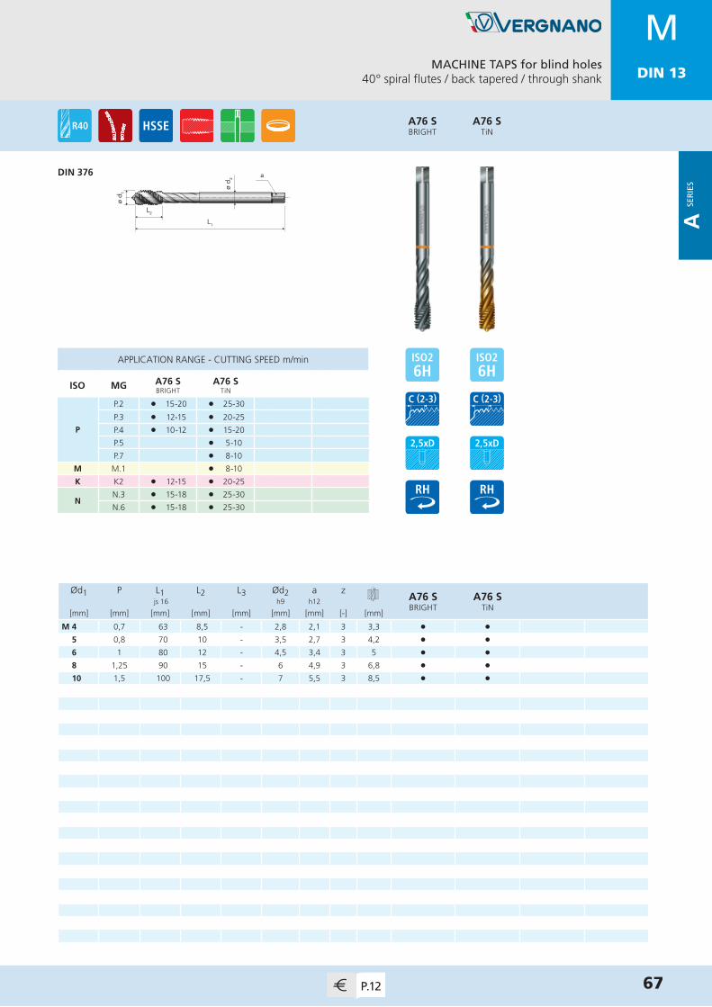
MDIN 13
ø d 2
L1
L2
ø d 1
a
Ød1 P L1 L2 L3 Ød2 a zA76 SBRIGHT
A76 STiN
js 16 h9 h12
[mm] [mm] [mm] [mm] [mm] [mm] [mm] [-] [mm]
M 4 0,7 63 8,5 - 2,8 2,1 3 3,3 • •5 0,8 70 10 - 3,5 2,7 3 4,2 • •6 1 80 12 - 4,5 3,4 3 5 • •8 1,25 90 15 - 6 4,9 3 6,8 • •10 1,5 100 17,5 - 7 5,5 3 8,5 • •
A76 STiN
A76 SBRIGHT
MACHINE TAPS for blind holes40° spiral flutes / back tapered / through shank
DIN 376
67P.12
APPLICATION RANGE - CUTTING SPEED m/min
ISO MG A76 SBRIGHT
A76 STiN
P
P.2 l 15-20 l 25-30
P.3 l 12-15 l 20-25
P.4 l 10-12 l 15-20
P.5 l 5-10
P.7 l 8-10
M M.1 l 8-10
K K2 l 12-15 l 20-25
NN.3 l 15-18 l 25-30
N.6 l 15-18 l 25-30
MDIN 13
A SE
RIE
S

MDIN 13
L1
L2
L3
ø d 1
ø d 2 a
ø d 1
L1
L2
ø d 2 a
Ød1 P L1 L2 L3 Ød2 a zA70 LBRIGHT
A70 LTiN
js 16 h9 h12
[mm] [mm] [mm] [mm] [mm] [mm] [mm] [-] [mm]
M 3 0,5 112 7 15 3,5 2,7 3 2,5 • •4 0,7 112 8,5 21 4,5 3,4 3 3,3 • •5 0,8 125 10 24,5 6 4,9 3 4,2 • •6 1 125 12 29 6 4,9 3 5 • •8 1,25 140 15 33 8 6,2 3 6,8 • •10 1,5 160 17,5 38 10 8 3 8,5 • •12 1,75 180 18 - 9 7 4 10,2 • •16 2 200 20,5 - 12 9 4 14 • •20 2,5 225 29,5 - 16 12 4 17,5 • •
APPLICATION RANGE - CUTTING SPEED m/min
ISO MG A70 LBRIGHT
A70 LTiN
PP.1 l 12-15 l 25-30
P.2 l 10-15 l 20-25
N
N.1 l 12-15
N.2 l 12-15 l 25-30
N.5 l 10-12
N.6 l 10-12 l 20-25
A70 LTiN
A70 LBRIGHT
MACHINE TAPS for blind holes40° spiral flutes / back tapered / long shank
NORM VERGNANO≤ M10
NORM VERGNANO≥ M12
68 P.12
MDIN 13
A SE
RIE
S

MDIN 13
ø d 2
L1
L2
L3
ø d 1
a
Ød1 P L1 L2 L3 Ød2 a zA120BRIGHT
A120VAP
A120TiN
js 16 h9 h12
[mm] [mm] [mm] [mm] [mm] [mm] [mm] [-] [mm]
M 2 0,4 45 5 14 2,8 2,1 3 1,6 • • •2,5 0,45 50 5 18 2,8 2,1 3 2,05 • • •3 0,5 56 5 21 3,5 2,7 3 2,5 • • •4 0,7 63 5 27 4,5 3,4 3 3,3 • • •5 0,8 70 6,5 30 6 4,9 3 4,2 • • •6 1 80 7 34,5 6 4,9 3 5 • • •8 1,25 90 9 38,5 8 6,2 3 6,8 • • •10 1,5 100 11 43 10 8 3 8,5 • • •12 1,75 110 13 - 9 7 3 10,2 • • •14 2 110 16,5 - 11 9 3 12 • • •16 2 110 19,5 - 12 9 3 14 • • •18 2,5 125 24 - 14 11 3 15,5 • • •20 2,5 140 25,5 - 16 12 3 17,5 • • •22 2,5 140 25,5 - 18 14,5 3 19,5 • • •24 3 160 32 - 18 14,5 3 21 • • •
A120TiN
A120VAP
A120BRIGHT
MACHINE TAPS for blind holes40° spiral flutes / back tapered
DIN 371≤ M10
DIN 376≥ M12
69P.13
MDIN 13
A SE
RIE
S
APPLICATION RANGE - CUTTING SPEED m/min
ISO MG A120BRIGHT
A120VAP
A120TiN
PP.1 l 12-15 l 12-15 l 25-30
P.2 l 10-15 l 10-15 l 20-25
N
N.1 l 12-15 l 12-15
N.2 l 12-15 l 12-15 l 25-30
N.5 l 10-12 l 10-12
N.6 l 10-12 l 10-12 l 20-25

MDIN 13
ø d 2
L1
L2
L3
ø d 1
a
ø d 2 a
L1
L2
ø d 1
Ød1 P L1 L2 L3 Ød2 a zA170
VAPA170TiX2
js 16 h9 h12
[mm] [mm] [mm] [mm] [mm] [mm] [mm] [-] [mm]
M 3 0,5 56 10 18 3,5 2,7 3 2,5 • •4 0,7 63 12 21 4,5 3,4 3 3,3 • •5 0,8 70 14 24,5 6 4,9 3 4,2 • •6 1 80 16 29 6 4,9 3 5 • •8 1,25 90 18 33 8 6,2 3 6,8 • •10 1,5 100 20 36 10 8 3 8,5 • •12 1,75 110 24 - 9 7 3 10,2 • •14 2 110 25 - 11 9 4 12 • •16 2 110 28 - 12 9 4 14 • •18 2,5 125 32 - 14 11 4 15,5 • •20 2,5 140 32 - 16 12 4 17,5 • •
APPLICATION RANGE - CUTTING SPEED m/min
ISO MG A170VAP
A170TiX2
P P.7 l 6-8 l 8-10
MM.1 l 6-8 l 8-10
M.2 l 5-7
A170TiX2
A170VAP
MACHINE TAPS for blind holes40° spiral flutes / for stainless steel
DIN 371≤ M10
DIN 376≥ M12
70 P.13
MDIN 13
A SE
RIE
S

MDIN 13
ø d 2
L2
L1
ø d 1
a
ø d 1
L2
ø d 2 a
L1
Ød1 P L1 L2 L3 Ød2 a zA62
BRIGHTA62TiH1
js 16 h9 h12
[mm] [mm] [mm] [mm] [mm] [mm] [mm] [-] [mm]
M 2 0,4 45 7 11 2,8 2,1 2 1,6 • •2,2 0,45 45 8 13 2,8 2,1 2 1,75 • •2,3 0,4 45 8 13 2,8 2,1 2 1,9 • •2,5 0,45 50 9 15 2,8 2,1 2 2,05 • •2,6 0,45 50 9 15 2,8 2,1 2 2,1 • •3 0,5 56 10 18 3,5 2,7 2 2,5 • •3,5 0,6 56 11 20 4 3 2 2,9 • •4 0,7 63 12 21 4,5 3,4 2 3,3 • •5 0,8 70 14 24,5 6 4,9 2 4,2 • •6 1 80 16 29 6 4,9 2 5 • •7 1 80 16 29 7 5,5 2 6 • •8 1,25 90 18 33 8 6,2 2 6,8 • •9 1,25 90 18 33 9 7 2 7,8 • •10 1,5 100 20 36 10 8 2 8,5 • •11 1,5 100 20 - 8 6,2 2 9,5 • •12 1,75 110 24 - 9 7 2 10,2 • •14 2 110 25 - 11 9 2 12 • •16 2 110 28 - 12 9 3 14 • •
APPLICATION RANGE - CUTTING SPEED m/min
ISO MG A62BRIGHT
A62TiH1
NN.1-2 l 12-15 l 25-30
N.5-6 l 10-12 l 20-25
SS.1 l 6-8 l 10-12
S.3 l 6-8 l 10-12
A62TiH1
A62BRIGHT
MACHINE TAPS for blind holesTwo 40° spiral flutes / for light alloys
DIN 371≤ M10
DIN 376≥ M11
71P.13
MDIN 13
A SE
RIE
S

MDIN 13
ø d 2
L1
L2
L3
ø d 1
a
Ød1 P L1 L2 L3 Ød2 a zA72
BRIGHTA72TiH1
js 16 h9 h12
[mm] [mm] [mm] [mm] [mm] [mm] [mm] [-] [mm]
M 3 0,5 56 7 15 3,5 2,7 3 2,5 • •4 0,7 63 8,5 21 4,5 3,4 3 3,3 • •5 0,8 70 10 24,5 6 4,9 3 4,2 • •6 1 80 12 29 6 4,9 3 5 • •8 1,25 90 15 33 8 6,2 3 6,8 • •10 1,5 100 17,5 38 10 8 3 8,5 • •12 1,75 110 18 - 9 7 3 10,2 • •14 2 110 20,5 - 11 9 3 12 • •16 2 110 20,5 - 12 9 3 14 • •18 2,5 125 25,5 - 14 11 3 15,5 • •20 2,5 140 29,5 - 16 12 3 17,5 • •
APPLICATION RANGE - CUTTING SPEED m/min
ISO MG A72BRIGHT
A72TiH1
P P.1 l 12-15 l 25-30
N
N.1-2 l 12-15 l 25-30
N.3 l 10-12 l 20-25
N.5-6 l 10-12 l 20-25
A72TiH1
A72BRIGHT
MACHINE TAPS for blind holes40° spiral flutes / back tapered / for light alloys
DIN 371≤ M10
DIN 376≥ M12
72 P.14
MDIN 13
A SE
RIE
S

MDIN 13
L1
L2
ø d 1
ø d 2 a
Ød1 P L1 L2 L3 Ød2 a zA9
BRIGHT js 16 h9 h12
[mm] [mm] [mm] [mm] [mm] [mm] [mm] [-] [mm]
M 4 0,7 90 25 - 2,8 2,1 3 3,3 •5 0,8 100 28 - 3,5 2,7 3 4,2 •6 1 110 32 - 4,5 3,4 3 5 •8 1,25 125 40 - 6 4,9 3 6,8 •10 1,5 140 45 - 7 5,5 3 8,5 •12 1,75 180 50 - 9 7 3 10,2 •14 2 200 56 - 11 9 3 12 •16 2 200 63 - 12 9 3 14 •18 2,5 220 63 - 14 11 3 15,5 •20 2,5 250 70 - 16 12 3 17,5 •22 2,5 280 80 - 18 14,5 3 19,5 •24 3 280 80 - 18 14,5 3 21 •27 3 315 90 - 20 16 3 24 •30 3,5 315 100 - 22 18 3 26,5 •
APPLICATION RANGE - CUTTING SPEED m/min
ISO MG A9BRIGHT
P
P.1 l 18-20
P.2 l 15-18
P.3 l 12-15
A9BRIGHT
MACHINE NUT TAPSStraight flutes
DIN 357
73P.14
MDIN 13
A SE
RIE
S

MDIN 13
ø d 2
L1
L2
L3
ø d 1
a
ø d 1
L1
L2
ø d 2 a
Ød1 P L1 L2 L3 Ød2 a zA80TiN
A80TiCN
js 16 h9 h12
[mm] [mm] [mm] [mm] [mm] [mm] [mm] [-] [mm]
M 2 0,4 45 7 11 2,8 2,1 3 1,85 • •2,5 0,45 50 9 15 2,8 2,1 3 2,3 • •3 0,5 56 10 18 3,5 2,7 4 2,8 • •3,5 0,6 56 11 20 4 3 4 3,25 • •4 0,7 63 12 21 4,5 3,4 5 3,7 • •5 0,8 70 14 24,5 6 4,9 5 4,65 • •6 1 80 16 29 6 4,9 5 5,55 • •8 1,25 90 18 33 8 6,2 5 7,4 • •10 1,5 100 20 36 10 8 5 9,3 • •12 1,75 110 24 - 9 7 5 11,2 • •14 2 110 25 - 11 9 6 13,1 • •16 2 110 28 - 12 9 6 15,1 • •
APPLICATION RANGE - CUTTING SPEED m/min
ISO MG A80TiN
A80TiCN
PP.1-2 l 40-45 l 40-45
P.3 l 35-40 l 35-40
N
N.1-2 l 40-45 l 40-45
N.3 l 35-40 l 35-40
N.5-6 l 40-45 l 40-45
A80TiCN
A80TiN
COLD FORMING TAPS for blind and through holesWithout oil grooves
DIN 2174 (371)≤ M10
DIN 2174 (376)≥ M12
74 P.14
MDIN 13
A SE
RIE
S

MDIN 13
Ød1 P L1 L2 L3 Ød2 a zA80 6GX
TiNA80 6GX
TiCN js 16 h9 h12
[mm] [mm] [mm] [mm] [mm] [mm] [mm] [-] [mm]
M 2 0,4 45 7 11 2,8 2,1 3 1,85 • •2,5 0,45 50 9 15 2,8 2,1 3 2,3 • •3 0,5 56 10 18 3,5 2,7 4 2,8 • •3,5 0,6 56 11 20 4 3 4 3,25 • •4 0,7 63 12 21 4,5 3,4 5 3,7 • •5 0,8 70 14 24,5 6 4,9 5 4,65 • •6 1 80 16 29 6 4,9 5 5,55 • •8 1,25 90 18 33 8 6,2 5 7,4 • •10 1,5 100 20 36 10 8 5 9,3 • •12 1,75 110 24 - 9 7 5 11,2 • •14 2 110 25 - 11 9 6 13,1 • •16 2 110 28 - 12 9 6 15,1 • •
A80 6GXTiCN
A80 6GXTiN
COLD FORMING TAPS for blind and through holesWithout oil grooves
75P.15
ø d 2
L1
L2
L3
ø d 1
a
ø d 1
L1
L2
ø d 2 a
DIN 2174 (371)≤ M10
DIN 2174 (376)≥ M12
APPLICATION RANGE - CUTTING SPEED m/min
ISO MG A80 6GXTiN
A80 6GXTiCN
PP.1-2 l 40-45 l 40-45
P.3 l 35-40 l 35-40
N
N.1-2 l 40-45 l 40-45
N.3 l 35-40 l 35-40
N.5-6 l 40-45 l 40-45
MDIN 13
A SE
RIE
S

MDIN 13
ø d 2
L1
L2
L3
ø d 1
a
ø d 1
L1
L2
ø d 2 a
Ød1 P L1 L2 L3 Ød2 a zA80 N
TiNA80 N
TiCN js 16 h9 h12
[mm] [mm] [mm] [mm] [mm] [mm] [mm] [-] [mm]
M 2 0,4 45 7 11 2,8 2,1 3 1,85 • •2,5 0,45 50 9 15 2,8 2,1 3 2,3 • •3 0,5 56 10 18 3,5 2,7 4 2,8 • •3,5 0,6 56 11 20 4 3 4 3,25 • •4 0,7 63 12 21 4,5 3,4 5 3,7 • •5 0,8 70 14 24,5 6 4,9 5 4,65 • •6 1 80 16 29 6 4,9 5 5,55 • •8 1,25 90 18 33 8 6,2 5 7,4 • •10 1,5 100 20 36 10 8 5 9,3 • •12 1,75 110 24 - 9 7 5 11,2 • •14 2 110 25 - 11 9 6 13,1 • •16 2 110 28 - 12 9 6 15,1 • •18 2,5 125 28 - 14 11 8 16,9 • •20 2,5 140 30 - 16 12 8 18,9 • •
A80 NTiCN
A80 NTiN
COLD FORMING TAPS for blind and through holesWith oil grooves
76 P.15
APPLICATION RANGE - CUTTING SPEED m/min
ISO MG A80 NTiN
A80 NTiCN
PP.1-2 l 40-45 l 40-45
P.3 l 35-40 l 35-40
N
N.1-2 l 40-45 l 40-45
N.3 l 35-40 l 35-40
N.5-6 l 40-45 l 40-45
DIN 2174 (371)≤ M10
DIN 2174 (376)≥ M12
MDIN 13
A SE
RIE
S
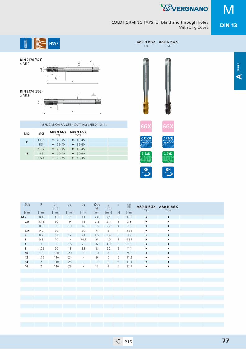
MDIN 13
Ød1 P L1 L2 L3 Ød2 a zA80 N 6GX
TiNA80 N 6GX
TiCN js 16 h9 h12
[mm] [mm] [mm] [mm] [mm] [mm] [mm] [-] [mm]
M 2 0,4 45 7 11 2,8 2,1 3 1,85 • •2,5 0,45 50 9 15 2,8 2,1 3 2,3 • •3 0,5 56 10 18 3,5 2,7 4 2,8 • •3,5 0,6 56 11 20 4 3 4 3,25 • •4 0,7 63 12 21 4,5 3,4 5 3,7 • •5 0,8 70 14 24,5 6 4,9 5 4,65 • •6 1 80 16 29 6 4,9 5 5,55 • •8 1,25 90 18 33 8 6,2 5 7,4 • •10 1,5 100 20 36 10 8 5 9,3 • •12 1,75 110 24 - 9 7 5 11,2 • •14 2 110 25 - 11 9 6 13,1 • •16 2 110 28 - 12 9 6 15,1 • •
A80 N 6GXTiCN
A80 N 6GXTiN
COLD FORMING TAPS for blind and through holesWith oil grooves
77P.15
APPLICATION RANGE - CUTTING SPEED m/min
ISO MG A80 N 6GXTiN
A80 N 6GXTiCN
PP.1-2 l 40-45 l 40-45
P.3 l 35-40 l 35-40
N
N.1-2 l 40-45 l 40-45
N.3 l 35-40 l 35-40
N.5-6 l 40-45 l 40-45
ø d 2
L1
L2
L3
ø d 1
a
ø d 1
L1
L2
ø d 2 a
DIN 2174 (371)≤ M10
DIN 2174 (376)≥ M12
MDIN 13
A SE
RIE
S

MDIN 13
ø d 2
L1
L2
L3
ø d 1
a
ø d 1
L1
L2
ø d 2 a
Ød1 P L1 L2 L3 Ød2 a zA190BRIGHT
js 16 h9 h12
[mm] [mm] [mm] [mm] [mm] [mm] [mm] [-] [mm]
EG-M 3 0,5 63 12 17 4,5 3,4 3 3,15 •4 0,7 70 14 24,5 6 4,9 3 4,2 •5 0,8 80 16 29 6 4,9 3 5,25 •6 1 90 18 33 8 6,2 3 6,3 •8 1,25 100 20 36 10 8 3 8,4 •10 1,5 100 22 - 9 7 3 10,5 •12 1,75 110 25 - 11 9 3 12,5 •14 2 110 28 - 12 9 3 14,5 •16 2 125 28 - 14 11 4 16,5 •
APPLICATION RANGE - CUTTING SPEED m/min
ISO MG A190BRIGHT
PP.2 l 10-12
P.3 l 8-10
K K.2 l 8-10
A190BRIGHT
MACHINE TAPS for blind and through holesStraight flutes / for wire thread inserts
DIN 40435≤ EG-M8
DIN 40435≥ EG-M10
78 P.16
EG-MDIN 8140-2
A SE
RIE
S

MDIN 13
ø d 2
L1
L2
L3
ø d 1
a
ø d 1
L2
ø d 2 a
L1
Ød1 P L1 L2 L3 Ød2 a zA2
ROUGHINGA2
FINISHINGA2SET
js 16 h9 h12
[mm] [mm] [mm] [mm] [mm] [mm] [mm] [-] [mm]
M 2 0,25 36 7,5 12 2,8 2,1 3 1,75 • • •2,3 0,25 36 8,5 13,5 2,8 2,1 3 2,05 • • •2,5 0,35 40 8,5 14,5 2,8 2,1 3 2,15 • • •2,6 0,35 40 8,5 14,5 2,8 2,1 3 2,25 • • •3 0,35 40 8 18 3,5 2,7 3 2,65 • • •3,5 0,35 45 9 19 4 3 3 3,15 • • •4 0,5 45 10 21 4,5 3,4 3 3,5 • • •4,5 0,5 50 12 23 6 4,9 3 4 • • •5 0,5 50 12 24 6 4,9 3 4,5 • • •6 0,5 56 14 28 6 4,9 3 5,5 • • •6 0,75 56 14 28 6 4,9 3 5,2 • • •7 0,75 56 14 - 6 4,9 3 6,2 • • •8 0,75 56 18 - 6 4,9 3 7,2 • • •8 1 63 22 - 6 4,9 3 7 • • •9 1 63 22 - 7 5,5 3 8 • • •10 0,75 63 20 - 7 5,5 4 9,2 • • •10 1 63 20 - 7 5,5 4 9 • • •10 1,25 70 24 - 7 5,5 3 8,8 • • •11 1 63 20 - 8 6,2 4 10 • • •12 0,75 70 22 - 9 7 4 11,2 • • •12 1 70 22 - 9 7 4 11 • • •12 1,25 70 22 - 9 7 4 10,8 • • •12 1,5 70 22 - 9 7 4 10,5 • • •14 1 70 22 - 11 9 4 13 • • •14 1,25 70 22 - 11 9 4 12,8 • • •14 1,5 70 22 - 11 9 4 12,5 • • •
APPLICATION RANGE - CUTTING SPEED m/min
ISO MG A2ROUGHING
A2FINISHING
A2SET
PP.1-4 l l l
P.7 l l l
K K.2 l l l
NN.1-3 l l l
N.5-7 l l l
A2SET
A2FINISHING
A2ROUGHING
HAND TAPS for blind and through holesIn sets of two pieces
DIN 2181≤ M6
DIN2181≥ M7
79P.16
MFDIN 13
»
A SE
RIE
S

MDIN 13
HAND TAPS for blind and through holesIn sets of two pieces
80 P.16
ø d 1
L2
ø d 2 a
L1
Ød1 P L1 L2 L3 Ød2 a zA2
ROUGHINGA2
FINISHINGA2SET
js 16 h9 h12
[mm] [mm] [mm] [mm] [mm] [mm] [mm] [-] [mm]
M 15 1 70 22 - 12 9 4 14 • • •15 1,5 70 22 - 12 9 4 13,5 • • •16 1 70 22 - 12 9 4 15 • • •16 1,25 70 22 - 12 9 4 14,8 • • •16 1,5 70 22 - 12 9 4 14,5 • • •18 1 80 22 - 14 11 4 17 • • •18 1,5 80 22 - 14 11 4 16,5 • • •18 2 80 22 - 14 11 4 16 • • •20 1 80 22 - 16 12 4 19 • • •20 1,5 80 22 - 16 12 4 18,5 • • •20 2 80 22 - 16 12 4 18 • • •22 1 80 22 - 18 14,5 4 21 • • •22 1,5 80 22 - 18 14,5 4 20,5 • • •22 2 80 22 - 18 14,5 4 20 • • •24 1 90 22 - 18 14,5 4 23 • • •24 1,5 90 22 - 18 14,5 4 22,5 • • •24 2 90 22 - 18 14,5 4 22 • • •25 1,5 90 22 - 18 14,5 4 23,5 • • •25 2 90 22 - 18 14,5 4 23 • • •26 1,5 90 22 - 18 14,5 4 24,5 • • •26 2 90 22 - 18 14,5 4 24 • • •27 1,5 90 22 - 20 16 4 25,5 • • •27 2 90 22 - 20 16 4 25 • • •28 1,5 90 22 - 20 16 4 26,5 • • •28 2 90 22 - 20 16 4 26 • • •30 1,5 90 22 - 22 18 4 28,5 • • •
APPLICATION RANGE - CUTTING SPEED m/min
ISO MG A2ROUGHING
A2FINISHING
A2SET
PP.1-4 l l l
P.7 l l l
K K.2 l l l
NN.1-3 l l l
N.5-7 l l l
A2SET
A2FINISHING
A2ROUGHING
DIN 2181
MFDIN 13
»
«
A SE
RIE
S

MDIN 13
81P.16
ø d 1
L2ø
d 2 a
L1
Ød1 P L1 L2 L3 Ød2 a zA2
ROUGHINGA2
FINISHINGA2SET
js 16 h9 h12
[mm] [mm] [mm] [mm] [mm] [mm] [mm] [-] [mm]
M 30 2 90 22 - 22 18 4 28 • • •32 1,5 90 22 - 22 18 5 30,5 • • •32 2 90 22 - 22 18 4 30 • • •33 2 100 25 - 25 20 4 31 • • •35 1,5 100 25 - 28 22 5 33,5 • • •35 2 125 30 - 28 22 5 33 • • •36 1,5 100 25 - 28 22 5 34,5 • • •36 2 125 30 - 28 22 5 34 • • •36 3 125 40 - 28 22 4 33 • • •38 1,5 100 25 - 28 22 5 36,5 • • •39 2 125 32 - 32 24 5 37 • • •39 3 125 40 - 32 24 4 36 • • •40 1,5 110 25 - 32 24 6 38,5 • • •40 2 125 32 - 32 24 5 38 • • •40 3 125 40 - 32 24 4 37 • • •42 1,5 110 25 - 32 24 6 40,5 • • •42 2 125 32 - 32 24 5 40 • • •42 3 125 40 - 32 24 4 39 • • •45 1,5 110 25 - 36 29 6 43,5 • • •45 2 125 32 - 36 29 5 43 • • •45 3 125 40 - 36 29 5 42 • • •48 1,5 140 25 - 36 29 6 46,5 • • •48 2 140 32 - 36 29 6 46 • • •48 3 140 40 - 36 29 5 45 • • •
APPLICATION RANGE - CUTTING SPEED m/min
ISO MG A2ROUGHING
A2FINISHING
A2SET
PP.1-4 l l l
P.7 l l l
K K.2 l l l
NN.1-3 l l l
N.5-7 l l l
A2SET
A2FINISHING
A2ROUGHING
DIN 2181
HAND TAPS for blind and through holesIn sets of two pieces
MFDIN 13
«
A SE
RIE
S

MDIN 13
ø d 2
L1
L2
L3
ø d 1
a
ø d 1
ø d 2 a
L1
L2
Ød1 P L1 L2 L3 Ød2 a zA2 LH
ROUGHINGA2 LH
FINISHINGA2 LH
SET js 16 h9 h12
[mm] [mm] [mm] [mm] [mm] [mm] [mm] [-] [mm]
M 4 0,5 45 10 21 4,5 3,4 3 3,5 • • •5 0,5 50 12 24 6 4,9 3 4,5 • • •6 0,75 56 14 28 6 4,9 3 5,2 • • •8 1 63 22 - 6 4,9 3 7 • • •10 1 63 20 - 7 5,5 4 9 • • •10 1,25 70 24 - 7 5,5 3 8,8 • • •11 1 63 20 - 8 6,2 4 10 • • •12 1 70 22 - 9 7 4 11 • • •12 1,25 70 22 - 9 7 4 10,8 • • •12 1,5 70 22 - 9 7 4 10,5 • • •14 1,5 70 22 - 11 9 4 12,5 • • •16 1,5 70 22 - 12 9 4 14,5 • • •18 1,5 80 22 - 14 11 4 16,5 • • •20 1,5 80 22 - 16 12 4 18,5 • • •
HAND TAPS for blind and through holesIn sets of two pieces
DIN 2181≤ M6
DIN 2181≥ M8
82 P.17
A2 LHSET
A2 LHFINISHING
A2 LHROUGHING
APPLICATION RANGE - CUTTING SPEED m/min
ISO MG A2 LHROUGHING
A2 LHFINISHING
A2 LHSET
PP.1-4 l l l
P.7 l l l
K K.2 l l l
NN.1-3 l l l
N.5-7 l l l
MFDIN 13
A SE
RIE
S

MDIN 13
ø d 1
L1
L2
ø d 2 a
Ød1 P L1 L2 L3 Ød2 a zA23 FCBRIGHT
A23 FCTiN
A23 FC LHBRIGHT
js 16 h9 h12
[mm] [mm] [mm] [mm] [mm] [mm] [mm] [-] [mm]
M 3 0,35 56 8 - 2,2 - 3 2,65 •3,5 0,35 56 9 - 2,5 2,1 3 3,15 •4 0,5 63 12 - 2,8 2,1 3 3,5 •5 0,5 70 14 - 3,5 2,7 3 4,5 •6 0,5 80 16 - 4,5 3,4 3 5,5 • •6 0,75 80 16 - 4,5 3,4 3 5,2 • • •7 0,75 80 16 - 5,5 4,3 3 6,2 • •8 0,75 80 16 - 6 4,9 3 7,2 •8 1 90 16 - 6 4,9 3 7 • • •9 1 90 16 - 7 5,5 3 8 •10 0,5 90 18 - 7 5,5 4 9,5 • •10 0,75 90 18 - 7 5,5 3 9,2 • 10 1 90 18 - 7 5,5 3 9 • • •10 1,25 100 18 - 7 5,5 3 8,8 • • •11 1 90 20 - 8 6,2 3 10 •12 0,75 100 22 - 9 7 4 11,2 • •12 1 100 22 - 9 7 4 11 • •12 1,25 100 22 - 9 7 3 10,8 • • •12 1,5 100 22 - 9 7 3 10,5 • • •14 1 100 22 - 11 9 4 13 • • 14 1,25 100 22 - 11 9 3 12,8 • •14 1,5 100 22 - 11 9 3 12,5 • • •15 1 100 22 - 12 9 4 14 •15 1,5 100 22 - 12 9 3 13,5 • 16 1 100 22 - 12 9 4 15 • •16 1,25 100 22 - 12 9 4 14,8 • •
APPLICATION RANGE - CUTTING SPEED m/min
ISO MG A23 FCBRIGHT
A23 FCTiN
A23 FC LHBRIGHT
P
P.1 l 20-25
P.2 l 10-12 l 15-20 l 10-12
P.3 l 8-10 l 12-15 l 8-10
K K.2 l 8-10 l 12-15 l 8-10
NN.1 l 20-25
N.5 l 15-20
A23 FC LHBRIGHT
A23 FCTiN
A23 FCBRIGHT
MACHINE TAPS for blind holesStraight flutes
DIN 374
83P.18
MFDIN 13
»
A SE
RIE
S

MDIN 13
MACHINE TAPS for blind holesStraight flutes
84 P.18
ø d 1
L1
L2
ø d 2 a
Ød1 P L1 L2 L3 Ød2 a zA23 FCBRIGHT
A23 FCTiN
A23 FC LHBRIGHT
js 16 h9 h12
[mm] [mm] [mm] [mm] [mm] [mm] [mm] [-] [mm]
M 16 1,5 100 22 - 12 9 3 14,5 • • •17 1 100 22 - 12 9 4 16 •17 1,5 100 22 - 12 9 4 15,5 •18 1 110 25 - 14 11 4 17 •18 1,5 110 25 - 14 11 4 16,5 • • •18 2 125 28 - 14 11 4 16 •20 1 125 25 - 16 12 4 19 •20 1,5 125 25 - 16 12 4 18,5 • • •20 2 140 28 - 16 12 4 18 •22 1 125 25 - 18 14,5 4 21 •22 1,5 125 25 - 18 14,5 4 20,5 • •22 2 140 28 - 18 14,5 4 20 •24 1 140 25 - 18 14,5 4 23 •24 1,5 140 25 - 18 14,5 4 22,5 •24 2 140 28 - 18 14,5 4 22 •25 1 140 25 - 18 14,5 4 24 •25 1,5 140 25 - 18 14,5 4 23,5 •25 2 140 28 - 18 14,5 4 23 •26 1 140 25 - 18 14,5 4 25 •26 1,5 140 25 - 18 14,5 4 24,5 •26 2 140 28 - 18 14,5 4 24 •27 1,5 140 28 - 20 16 4 25,5 •27 2 140 28 - 20 16 4 25 •28 1,5 140 28 - 20 16 4 26,5 •28 2 140 28 - 20 16 4 26 •30 1 150 25 - 22 18 5 29 •
A23 FC LHBRIGHT
A23 FCTiN
A23 FCBRIGHT
DIN 374
APPLICATION RANGE - CUTTING SPEED m/min
ISO MG A23 FCBRIGHT
A23 FCTiN
A23 FC LHBRIGHT
P
P.1 l 20-25
P.2 l 10-12 l 15-20 l 10-12
P.3 l 8-10 l 12-15 l 8-10
K K.2 l 8-10 l 12-15 l 8-10
NN.1 l 20-25
N.5 l 15-20
MFDIN 13
»
«
A SE
RIE
S

MDIN 13
85P.19
ø d 1
L1
L2
ø d 2 a
Ød1 P L1 L2 L3 Ød2 a zA23 FCBRIGHT
js 16 h9 h12
[mm] [mm] [mm] [mm] [mm] [mm] [mm] [-] [mm]
M 30 1,5 150 28 - 22 18 4 28,5 •30 2 150 28 - 22 18 4 28 •32 1,5 150 28 - 22 18 5 30,5 •32 2 150 28 - 22 18 4 30 •33 1,5 160 30 - 25 20 5 31,5 •33 2 160 30 - 25 20 4 31 •35 1,5 170 30 - 28 22 5 33,5 •35 2 170 30 - 28 22 5 33 •36 1,5 170 30 - 28 22 5 34,5 •36 2 170 30 - 28 22 5 34 •36 3 200 56 - 28 22 4 33 •39 3 200 60 - 32 24 5 36 •40 1,5 170 30 - 32 24 5 38,5 •40 2 170 30 - 32 24 5 38 •40 3 200 60 - 32 24 5 37 •42 1,5 170 30 - 32 24 6 40,5 •42 2 170 30 - 32 24 5 40 •42 3 200 60 - 32 24 5 39 •45 1,5 180 32 - 36 29 6 43,5 •45 2 180 32 - 36 29 5 43 •45 3 200 50 - 36 29 5 42 •48 1,5 190 32 - 36 29 6 46,5 •48 2 190 32 - 36 29 6 46 •48 3 225 50 - 36 29 5 45 • 52 1,5 190 32 - 40 32 6 50,5 •52 2 190 32 - 40 32 6 50 •52 3 225 50 - 40 32 5 49 •
A23 FCBRIGHT
MACHINE TAPS for blind holesStraight flutes
DIN 374
APPLICATION RANGE - CUTTING SPEED m/min
ISO MG A23 FCBRIGHT
PP.2 l 10-12
P.3 l 8-10
K K.2 l 8-10
MFDIN 13
«
A SE
RIE
S

MDIN 13
Ød1 P L1 L2 L3 Ød2 a zA45
NITRIDEDA45TiCN
js 16 h9 h12
[mm] [mm] [mm] [mm] [mm] [mm] [mm] [-] [mm]
M 4 0,5 63 10 - 2,8 2,1 3 3,5 • •5 0,5 70 12 - 3,5 2,7 3 4,5 • •6 0,75 80 14 - 4,5 3,4 3 5,2 • •8 1 90 16 - 6 4,9 4 7 • •9 1 90 16 - 7 5,5 4 8 •10 1 90 18 - 7 5,5 4 9 • •10 1,25 100 18 - 7 5,5 4 8,8 • •11 1 90 20 - 8 6,2 4 10 •12 1 100 22 - 9 7 4 11 •12 1,25 100 22 - 9 7 4 10,8 • •12 1,5 100 22 - 9 7 4 10,5 • •14 1 100 22 - 11 9 4 13 •14 1,25 100 22 - 11 9 4 12,8 • •14 1,5 100 22 - 11 9 4 12,5 • •16 1 100 22 - 12 9 4 15 •16 1,5 100 22 - 12 9 4 14,5 • •18 1,5 110 25 - 14 11 4 16,5 • • 20 1,5 125 25 - 16 12 4 18,5 • •22 1,5 125 25 - 18 14,5 4 20,5 •24 1,5 140 25 - 18 14,5 5 22,5 •24 2 140 28 - 18 14,5 5 22 •27 1,5 140 28 - 20 16 5 25,5 •27 2 140 28 - 20 16 5 25 •30 1,5 150 28 - 22 18 5 28,5 •30 2 150 28 - 22 18 5 28 •
APPLICATION RANGE - CUTTING SPEED m/min
ISO MG A45NITRIDED
A45TiCN
K K.1 l 15-20 l 40-45
N
N.4 l 15-20 l 40-45
N.7 l 15-20 l 40-45
N.9-10 l 20-25 l 45-50
A45TiCN
A45NITRIDED
MACHINE TAPS for blind and through holesStraight flutes / for cast iron
86 P.19
ø d 1
L1
L2
ø d 2 aDIN 374
MFDIN 13
A SE
RIE
S

MDIN 13
ø d 1
L1
L2
ø d 2 a
Ød1 P L1 L2 L3 Ød2 a zA17 SBRIGHT
A17 SVAP
A17 STiN
A17 STiCN
js 16 h9 h12
[mm] [mm] [mm] [mm] [mm] [mm] [mm] [-] [mm]
M 4 0,5 63 12 - 2,8 2,1 3 3,5 •5 0,5 70 14 - 3,5 2,7 3 4,5 •6 0,75 80 16 - 4,5 3,4 3 5,2 • • • •7 0,75 80 16 - 5,5 4,3 3 6,2 •8 0,75 80 16 - 6 4,9 3 7,2 •8 1 90 16 - 6 4,9 3 7 • • • •9 1 90 16 - 7 5,5 3 8 •10 0,75 90 18 - 7 5,5 4 9,2 •10 1 90 18 - 7 5,5 4 9 • • • •10 1,25 100 18 - 7 5,5 3 8,8 • • • •11 1 90 20 - 8 6,2 4 10 •12 1 100 22 - 9 7 4 11 • • • •12 1,25 100 22 - 9 7 4 10,8 • • • •12 1,5 100 22 - 9 7 3 10,5 • • • •14 1 100 22 - 11 9 4 13 •14 1,25 100 22 - 11 9 4 12,8 • • • •14 1,5 100 22 - 11 9 4 12,5 • • • •15 1 100 22 - 12 9 4 14 •15 1,5 100 22 - 12 9 4 13,5 •16 1 100 22 - 12 9 4 15 •16 1,5 100 22 - 12 9 4 14,5 • • • •18 1 110 25 - 14 11 4 17 •18 1,5 110 25 - 14 11 4 16,5 • • • •20 1 125 25 - 16 12 4 19 •20 1,5 125 25 - 16 12 4 18,5 • • • • 22 1 125 25 - 18 14,5 4 21 •
APPLICATION RANGE - CUTTING SPEED m/min
ISO MG A17 SBRIGHT
A17 SVAP
A17 STiN
A17 STiCN
P
P.2 l 20-25 l 20-25 l 30-35 l 30-35
P.3 l 15-20 l 15-20 l 25-30 l 25-30
P.4 l 12-15 l 12-15 l 20-25 l 20-25
P.5 l 10-15 l 10-15
P.7 l 10-15 l 10-15
M M.1 l 10-15 l 10-15
K K.2 l 15-20 l 15-20 l 25-30 l 25-30
NN.2-3 l 20-25 l 20-25 l 30-35 l 30-35
N.6 l 15-18 l 15-18 l 25-30 l 25-30
A17 STiCN
A17 STiN
A17 SVAP
A17 SBRIGHT
MACHINE TAPS for through holesStraight flutes with spiral point
DIN 374
87P.20
MFDIN 13
»
A SE
RIE
S
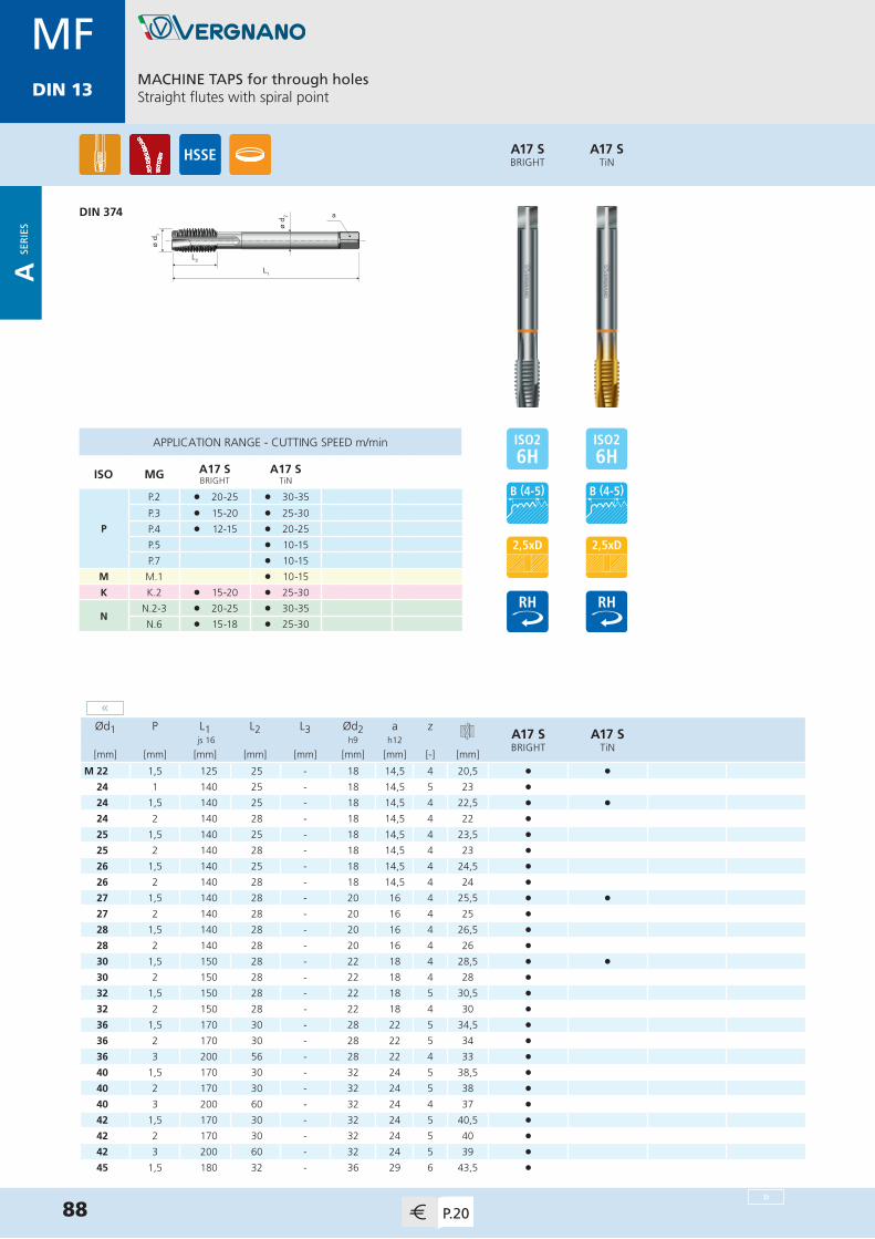
MDIN 13
MACHINE TAPS for through holesStraight flutes with spiral point
88 P.20
ø d 1
L1
L2
ø d 2 a
Ød1 P L1 L2 L3 Ød2 a zA17 SBRIGHT
A17 STiN
js 16 h9 h12
[mm] [mm] [mm] [mm] [mm] [mm] [mm] [-] [mm]
M 22 1,5 125 25 - 18 14,5 4 20,5 • •24 1 140 25 - 18 14,5 5 23 •24 1,5 140 25 - 18 14,5 4 22,5 • •24 2 140 28 - 18 14,5 4 22 • 25 1,5 140 25 - 18 14,5 4 23,5 •25 2 140 28 - 18 14,5 4 23 •26 1,5 140 25 - 18 14,5 4 24,5 •26 2 140 28 - 18 14,5 4 24 •27 1,5 140 28 - 20 16 4 25,5 • •27 2 140 28 - 20 16 4 25 •28 1,5 140 28 - 20 16 4 26,5 •28 2 140 28 - 20 16 4 26 •30 1,5 150 28 - 22 18 4 28,5 • •30 2 150 28 - 22 18 4 28 •32 1,5 150 28 - 22 18 5 30,5 •32 2 150 28 - 22 18 4 30 •36 1,5 170 30 - 28 22 5 34,5 •36 2 170 30 - 28 22 5 34 •36 3 200 56 - 28 22 4 33 •40 1,5 170 30 - 32 24 5 38,5 •40 2 170 30 - 32 24 5 38 •40 3 200 60 - 32 24 4 37 •42 1,5 170 30 - 32 24 5 40,5 •42 2 170 30 - 32 24 5 40 •42 3 200 60 - 32 24 5 39 •45 1,5 180 32 - 36 29 6 43,5 •
APPLICATION RANGE - CUTTING SPEED m/min
ISO MG A17 SBRIGHT
A17 STiN
P
P.2 l 20-25 l 30-35
P.3 l 15-20 l 25-30
P.4 l 12-15 l 20-25
P.5 l 10-15
P.7 l 10-15
M M.1 l 10-15
K K.2 l 15-20 l 25-30
NN.2-3 l 20-25 l 30-35
N.6 l 15-18 l 25-30
A17 STiN
A17 SBRIGHT
DIN 374
MFDIN 13
»
«
A SE
RIE
S

MDIN 13
89P.20
ø d 1
L1
L2
ø d 2 a
Ød1 P L1 L2 L3 Ød2 a zA17 SBRIGHT
js 16 h9 h12
[mm] [mm] [mm] [mm] [mm] [mm] [mm] [-] [mm]
M 45 2 180 32 - 36 29 5 43 •45 3 200 50 - 36 29 5 42 •48 1,5 190 32 - 36 29 6 46,5 •48 2 190 32 - 36 29 5 46 •48 3 225 50 - 36 29 5 45 •
APPLICATION RANGE - CUTTING SPEED m/min
ISO MG A17 SBRIGHT
P
P.2 l 20-25
P.3 l 15-20
P.4 l 12-15
K K.2 l 15-20
NN.2-3 l 20-25
N.6 l 15-18
A17 SBRIGHT
DIN 374
MACHINE TAPS for through holesStraight flutes with spiral point
MFDIN 13
«
A SE
RIE
S
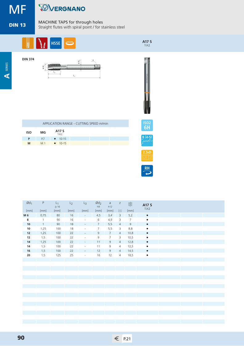
MDIN 13
Ød1 P L1 L2 L3 Ød2 a zA17 S
TiX2 js 16 h9 h12
[mm] [mm] [mm] [mm] [mm] [mm] [mm] [-] [mm]
M 6 0,75 80 16 - 4,5 3,4 3 5,2 •8 1 90 16 - 6 4,9 3 7 •10 1 90 18 - 7 5,5 4 9 •10 1,25 100 18 - 7 5,5 3 8,8 •12 1,25 100 22 - 9 7 4 10,8 •12 1,5 100 22 - 9 7 3 10,5 •14 1,25 100 22 - 11 9 4 12,8 •14 1,5 100 22 - 11 9 4 12,5 •16 1,5 100 22 - 12 9 4 14,5 •20 1,5 125 25 - 16 12 4 18,5 •
APPLICATION RANGE - CUTTING SPEED m/min
ISO MG A17 STiX2
P P.7 l 10-15
M M.1 l 10-15
A17 STiX2
MACHINE TAPS for through holesStraight flutes with spiral point / for stainless steel
90 P.21
ø d 1
L1
L2
ø d 2 aDIN 374
MFDIN 13
A SE
RIE
S
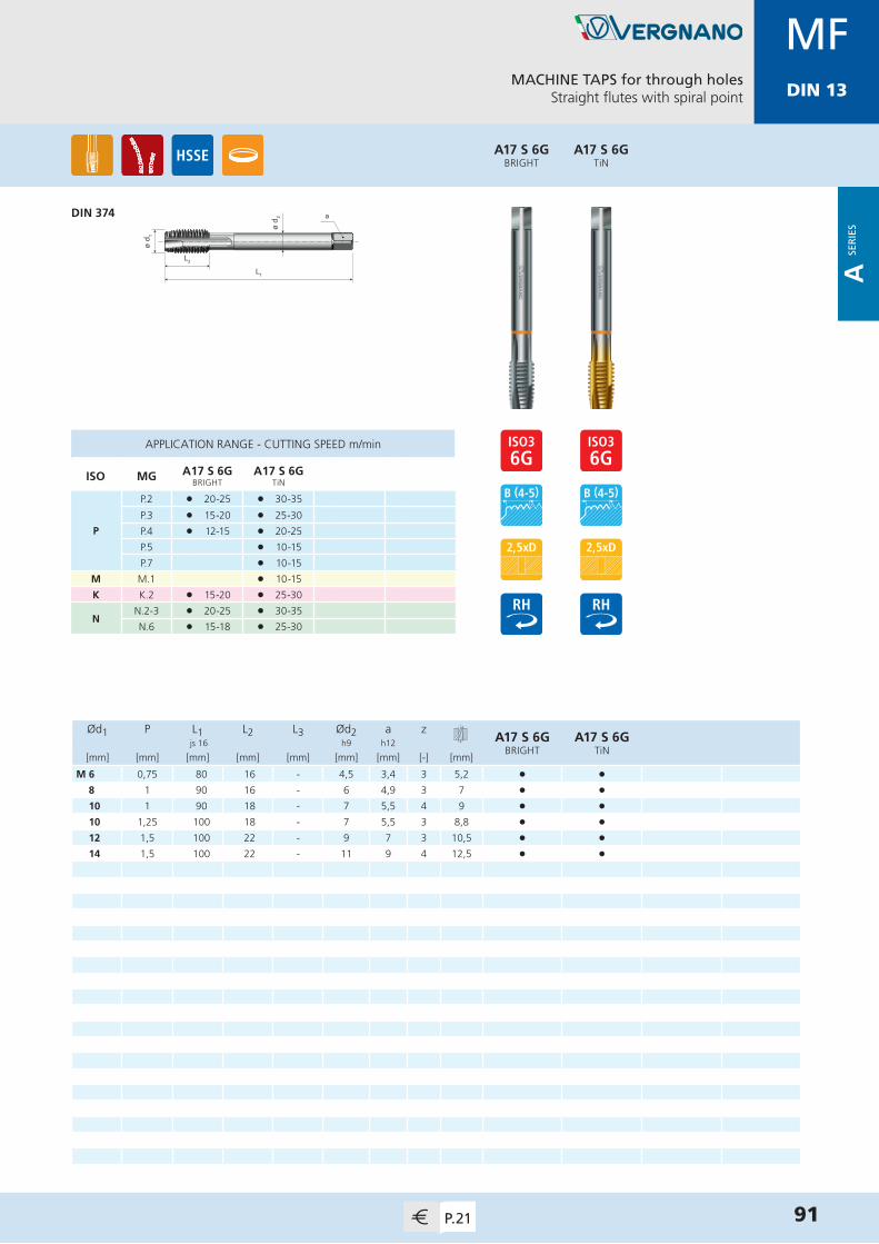
MDIN 13
Ød1 P L1 L2 L3 Ød2 a zA17 S 6G
BRIGHTA17 S 6G
TiN js 16 h9 h12
[mm] [mm] [mm] [mm] [mm] [mm] [mm] [-] [mm]
M 6 0,75 80 16 - 4,5 3,4 3 5,2 • •8 1 90 16 - 6 4,9 3 7 • •10 1 90 18 - 7 5,5 4 9 • •10 1,25 100 18 - 7 5,5 3 8,8 • •12 1,5 100 22 - 9 7 3 10,5 • •14 1,5 100 22 - 11 9 4 12,5 • •
A17 S 6GTiN
MACHINE TAPS for through holesStraight flutes with spiral point
91P.21
A17 S 6GBRIGHT
ø d 1
L1
L2
ø d 2 aDIN 374
APPLICATION RANGE - CUTTING SPEED m/min
ISO MG A17 S 6GBRIGHT
A17 S 6GTiN
P
P.2 l 20-25 l 30-35
P.3 l 15-20 l 25-30
P.4 l 12-15 l 20-25
P.5 l 10-15
P.7 l 10-15
M M.1 l 10-15
K K.2 l 15-20 l 25-30
NN.2-3 l 20-25 l 30-35
N.6 l 15-18 l 25-30
MFDIN 13
A SE
RIE
S

MDIN 13
ø d 1
L1
L2
ø d 2 a
Ød1 P L1 L2 L3 Ød2 a zA30
BRIGHTA30TiN
js 16 h9 h12
[mm] [mm] [mm] [mm] [mm] [mm] [mm] [-] [mm]
M 3 0,35 56 8 - 2,2 - 3 2,65 •3,5 0,35 56 9 - 2,5 2,1 3 3,15 •4 0,5 63 12 - 2,8 2,1 3 3,5 •5 0,5 70 14 - 3,5 2,7 3 4,5 •6 0,75 80 16 - 4,5 3,4 3 5,2 • •7 0,75 80 16 - 5,5 4,3 3 6,2 •8 0,75 80 16 - 6 4,9 3 7,2 •8 1 90 16 - 6 4,9 3 7 • •9 1 90 16 - 7 5,5 3 8 •10 0,75 90 18 - 7 5,5 3 9,2 •10 1 90 18 - 7 5,5 3 9 • •10 1,25 100 18 - 7 5,5 3 8,8 • •11 1 90 20 - 8 6,2 3 10 •12 1 100 22 - 9 7 3 11 • •12 1,25 100 22 - 9 7 3 10,8 • •12 1,5 100 22 - 9 7 3 10,5 • •14 1 100 22 - 11 9 3 13 •14 1,25 100 22 - 11 9 3 12,8 • •14 1,5 100 22 - 11 9 3 12,5 • •15 1 100 22 - 12 9 4 14 •15 1,5 100 22 - 12 9 3 13,5 •16 1 100 22 - 12 9 4 15 •16 1,25 100 22 - 12 9 4 14,8 •16 1,5 100 22 - 12 9 4 14,5 • •17 1 100 22 - 12 9 4 16 •17 1,5 100 22 - 12 9 4 15,5 •
A30TiN
A30BRIGHT
MACHINE TAPS for blind holes15° spiral flutes
DIN 374
92 P.21
APPLICATION RANGE - CUTTING SPEED m/min
ISO MG A30BRIGHT
A30TiN
P
P.1 l 18-20 l 30-35
P.2 l 15-18 l 25-30
P.3 l 12-15 l 20-25
P.4 l 10-12 l 15-20
P.5 l 5-10
K K.2 l 12-15 l 20-25
N
N.1 l 18-20
N.2-3 l 15-18 l 25-30
N.5 l 15-18
N.6 l 12-15 l 20-25
MFDIN 13
»
A SE
RIE
S

MDIN 13
MACHINE TAPS for blind holes15° spiral flutes
93P.22
ø d 1
L1
L2
ø d 2 a
Ød1 P L1 L2 L3 Ød2 a zA30
BRIGHTA30TiN
js 16 h9 h12
[mm] [mm] [mm] [mm] [mm] [mm] [mm] [-] [mm]
M 18 1 110 25 - 14 11 4 17 •18 1,5 110 25 - 14 11 4 16,5 • •20 1 125 25 - 16 12 4 19 •20 1,5 125 25 - 16 12 4 18,5 • •22 1 125 25 - 18 14,5 4 21 •22 1,5 125 25 - 18 14,5 4 20,5 • •24 1 140 25 - 18 14,5 4 23 •24 1,5 140 25 - 18 14,5 4 22,5 • •24 2 140 28 - 18 14,5 4 22 •25 1 140 25 - 18 14,5 4 24 •25 1,5 140 25 - 18 14,5 4 23,5 •25 2 140 28 - 18 14,5 4 23 •26 1 140 25 - 18 14,5 4 25 •26 1,5 140 25 - 18 14,5 4 24,5 •26 2 140 28 - 18 14,5 4 24 •27 1,5 140 28 - 20 16 4 25,5 • •27 2 140 28 - 20 16 4 25 •28 1,5 140 28 - 20 16 4 26,5 • 28 2 140 28 - 20 16 4 26 •30 1 150 25 - 22 18 5 29 •30 1,5 150 28 - 22 18 4 28,5 • •30 2 150 28 - 22 18 4 28 •32 1,5 150 28 - 22 18 5 30,5 •32 2 150 28 - 22 18 4 30 •36 1,5 170 30 - 28 22 5 34,5 •36 2 170 30 - 28 22 5 34 •
A30TiN
A30BRIGHT
DIN 374
APPLICATION RANGE - CUTTING SPEED m/min
ISO MG A30BRIGHT
A30TiN
P
P.1 l 18-20 l 30-35
P.2 l 15-18 l 25-30
P.3 l 12-15 l 20-25
P.4 l 10-12 l 15-20
P.5 l 5-10
K K.2 l 12-15 l 20-25
N
N.1 l 18-20
N.2-3 l 15-18 l 25-30
N.5 l 15-18
N.6 l 12-15 l 20-25
MFDIN 13
«
»
A SE
RIE
S
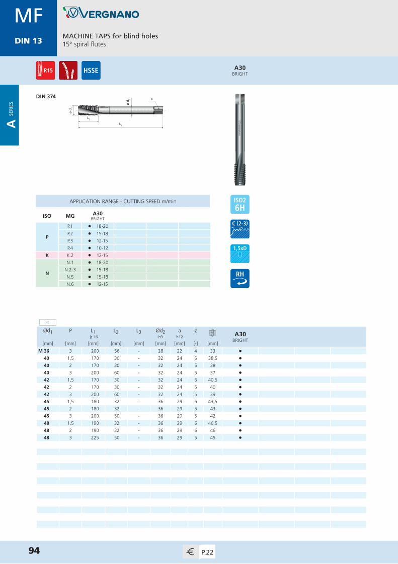
MDIN 13
94 P.22
ø d 1
L1
L2
ø d 2 a
Ød1 P L1 L2 L3 Ød2 a zA30
BRIGHT js 16 h9 h12
[mm] [mm] [mm] [mm] [mm] [mm] [mm] [-] [mm]
M 36 3 200 56 - 28 22 4 33 •40 1,5 170 30 - 32 24 5 38,5 •40 2 170 30 - 32 24 5 38 •40 3 200 60 - 32 24 5 37 • 42 1,5 170 30 - 32 24 6 40,5 •42 2 170 30 - 32 24 5 40 •42 3 200 60 - 32 24 5 39 •45 1,5 180 32 - 36 29 6 43,5 •45 2 180 32 - 36 29 5 43 •45 3 200 50 - 36 29 5 42 •48 1,5 190 32 - 36 29 6 46,5 •48 2 190 32 - 36 29 6 46 •48 3 225 50 - 36 29 5 45 •
A30BRIGHT
MACHINE TAPS for blind holes15° spiral flutes
DIN 374
APPLICATION RANGE - CUTTING SPEED m/min
ISO MG A30BRIGHT
P
P.1 l 18-20
P.2 l 15-18
P.3 l 12-15
P.4 l 10-12
K K.2 l 12-15
N
N.1 l 18-20
N.2-3 l 15-18
N.5 l 15-18
N.6 l 12-15
MFDIN 13
«
A SE
RIE
S

MDIN 13
ø d 1
L1
L2
ø d 2 a
Ød1 P L1 L2 L3 Ød2 a zA71 SBRIGHT
A71 SVAP
A71 STiN
A71 STiCN
js 16 h9 h12
[mm] [mm] [mm] [mm] [mm] [mm] [mm] [-] [mm]
M 6 0,75 80 7,5 - 4,5 3,4 3 5,2 • • • •8 1 90 10 - 6 4,9 3 7 • • • •10 1 90 10 - 7 5,5 3 9 • • • •10 1,25 100 11,5 - 7 5,5 3 8,8 • • • •12 1 100 13 - 9 7 4 11 • • • •12 1,25 100 13,5 - 9 7 4 10,8 • • • •12 1,5 100 14 - 9 7 4 10,5 • • • •14 1,5 100 15,5 - 11 9 4 12,5 • • • •16 1,5 100 15,5 - 12 9 4 14,5 • • • •18 1,5 110 16 - 14 11 4 16,5 • • • •20 1 125 15 - 16 12 4 19 •20 1,5 125 17 - 16 12 4 18,5 • • • • 22 1,5 125 19 - 18 14,5 4 20,5 • • • •24 1,5 140 21 - 18 14,5 4 22,5 • •24 2 140 26 - 18 14,5 4 22 •26 1,5 140 23 - 18 14,5 4 24,5 •27 1,5 140 23 - 20 16 4 25,5 • •27 2 140 28 - 20 16 4 25 •28 1,5 140 23 - 20 16 4 26,5 •30 1,5 150 25 - 22 18 5 28,5 • •30 2 150 29 - 22 18 5 28 •36 3 200 46 - 28 22 5 33 •42 3 200 51 - 32 24 6 39 •
APPLICATION RANGE - CUTTING SPEED m/min
ISO MG A71 SBRIGHT
A71 SVAP
A71 STiN
A71 STiCN
P
P.2 l 15-20 l 15-20 l 25-30 l 25-30
P.3 l 12-15 l 12-15 l 20-25 l 20-25
P.4 l 10-12 l 10-12 l 15-20 l 15-20
P.5 l 5-10 l 5-10
P.7 l 8-10 l 8-10
M M.1 l 8-10 l 8-10
K K.2 l 12-15 l 12-15 l 20-25 l 20-25
NN.3 l 15-18 l 15-18 l 25-30 l 25-30
N.6 l 15-18 l 15-18 l 25-30 l 25-30
A71 STiCN
A71 STiN
A71 SVAP
A71 SBRIGHT
MACHINE TAPS for blind holes40° spiral flutes / back tapered
DIN 374
95P.23
MFDIN 13
A SE
RIE
S
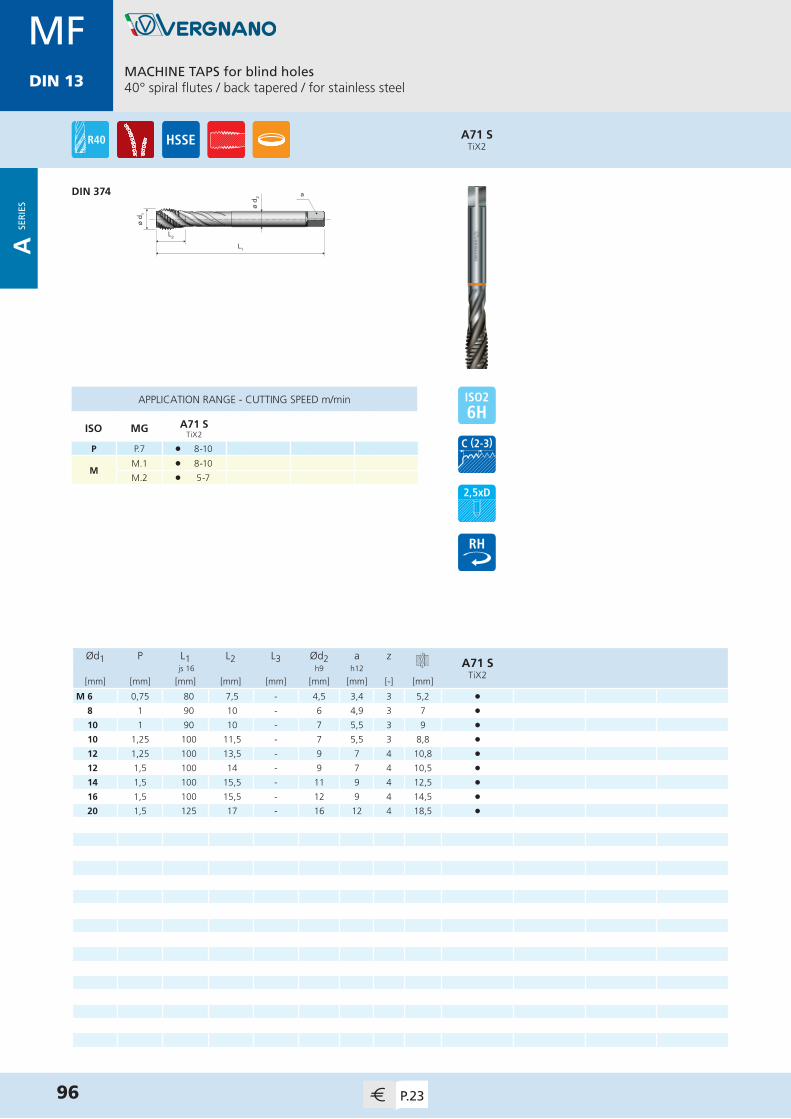
MDIN 13
Ød1 P L1 L2 L3 Ød2 a zA71 S
TiX2 js 16 h9 h12
[mm] [mm] [mm] [mm] [mm] [mm] [mm] [-] [mm]
M 6 0,75 80 7,5 - 4,5 3,4 3 5,2 •8 1 90 10 - 6 4,9 3 7 •10 1 90 10 - 7 5,5 3 9 •10 1,25 100 11,5 - 7 5,5 3 8,8 •12 1,25 100 13,5 - 9 7 4 10,8 •12 1,5 100 14 - 9 7 4 10,5 •14 1,5 100 15,5 - 11 9 4 12,5 •16 1,5 100 15,5 - 12 9 4 14,5 •20 1,5 125 17 - 16 12 4 18,5 •
APPLICATION RANGE - CUTTING SPEED m/min
ISO MG A71 STiX2
P P.7 l 8-10
MM.1 l 8-10
M.2 l 5-7
MACHINE TAPS for blind holes40° spiral flutes / back tapered / for stainless steel
96 P.23
ø d 1
L1
L2
ø d 2 a
A71 STiX2
DIN 374
MFDIN 13
A SE
RIE
S

MDIN 13
A71 S 6GTiN
MACHINE TAPS for blind holes40° spiral flutes / back tapered
97P.23
MDIN 13
ø d 1
L1
L2
ø d 2 a
Ød1 P L1 L2 L3 Ød2 a zA71 S 6G
BRIGHTA71 S 6G
TiN js 16 h9 h12
[mm] [mm] [mm] [mm] [mm] [mm] [mm] [-] [mm]
M 6 0,75 80 7,5 - 4,5 3,4 3 5,2 • •8 1 90 10 - 6 4,9 3 7 • •10 1 90 10 - 7 5,5 3 9 • •10 1,25 100 11,5 - 7 5,5 3 8,8 • •12 1 100 13 - 9 7 4 11 • •12 1,25 100 13,5 - 9 7 4 10,8 • •12 1,5 100 14 - 9 7 4 10,5 • •14 1,5 100 15,5 - 11 9 4 12,5 • •
APPLICATION RANGE - CUTTING SPEED m/min
ISO MG A71 S 6GBRIGHT
A71 S 6GTiN
P
P.2 l 15-20 l 25-30
P.3 l 12-15 l 20-25
P.4 l 10-12 l 15-20
P.5 l 5-10
P.7 l 8-10
M M.1 l 8-10
K K.2 l 12-15 l 20-25
NN.3 l 15-18 l 25-30
N.6 l 15-18 l 25-30
A71 S 6GBRIGHT
DIN 374
MFDIN 13
A SE
RIE
S

MDIN 13
L1
L2
ø d 1
ø d 2 a
Ød1 P L1 L2 L3 Ød2 a zA10
BRIGHT js 16 h9 h12
[mm] [mm] [mm] [mm] [mm] [mm] [mm] [-] [mm]
M 4 0,5 80 20 - 2,8 2,1 3 3,5 •5 0,5 85 22 - 3,5 2,7 3 4,5 •8 1 115 30 - 6 4,9 3 7 •10 1 130 35 - 7 5,5 3 9 •10 1,25 140 45 - 7 5,5 3 8,8 •12 1,25 160 45 - 9 7 3 10,8 •12 1,5 160 45 - 9 7 3 10,5 •14 1,5 180 45 - 11 9 3 12,5 •16 1,5 190 48 - 12 9 3 14,5 •18 1,5 200 48 - 14 11 3 16,5 •20 1,5 220 50 - 16 12 3 18,5 •
APPLICATION RANGE - CUTTING SPEED m/min
ISO MG A10BRIGHT
P
P.1 l 18-20
P.2 l 15-18
P.3 l 12-15
A10BRIGHT
MACHINE NUT TAPSStraight flutes
98 P.24
NORM VERGNANO
MFDIN 13
A SE
RIE
S

MDIN 13
ø d 2
L1
L2
L3
ø d 1
a
ø d 1
L1
L2
ø d 2 a
Ød1 P L1 L2 L3 Ød2 a zA81TiN
A81TiCN
js 16 h9 h12
[mm] [mm] [mm] [mm] [mm] [mm] [mm] [-] [mm]
M 3 0,35 56 10 18 3,5 2,7 4 2,85 • •4 0,5 63 12 21 4,5 3,4 5 3,8 • •5 0,5 70 14 24,5 6 4,9 5 4,8 • •6 0,75 80 16 29 6 4,9 5 5,65 • •8 1 90 18 33 8 6,2 5 7,55 • •10 1 90 18 34 10 8 6 9,55 • •10 1,25 100 20 36 10 8 6 9,4 • •12 1 100 22 - 9 7 6 11,55 • •12 1,25 100 22 - 9 7 6 11,4 • •12 1,5 100 22 - 9 7 6 11,3 • •14 1,25 100 22 - 11 9 6 13,4 • •14 1,5 100 22 - 11 9 6 13,3 • •16 1,5 100 22 - 12 9 6 15,3 • •
APPLICATION RANGE - CUTTING SPEED m/min
ISO MG A81TiN
A81TiCN
PP.1-2 l 40-45 l 40-45
P.3 l 35-40 l 35-40
N
N.1-2 l 40-45 l 40-45
N.3 l 35-40 l 35-40
N.5-6 l 40-45 l 40-45
A81TiCN
A81TiN
COLD FORMING TAPS for blind and through holesWithout oil grooves
DIN 2174 (371)≤ M10x1,25
DIN 2174 (374)≥ M12x1
99P.24
MFDIN 13
A SE
RIE
S

MDIN 13
COLD FORMING TAPS for blind and through holesWithout oil grooves
100 P.24
ø d 2
L1
L2
L3
ø d 1
a
ø d 1
L1
L2
ø d 2 a
Ød1 P L1 L2 L3 Ød2 a zA81 6GX
TiNA81 6GX
TiCN js 16 h9 h12
[mm] [mm] [mm] [mm] [mm] [mm] [mm] [-] [mm]
M 3 0,35 56 10 18 3,5 2,7 4 2,85 • •4 0,5 63 12 21 4,5 3,4 5 3,8 • •5 0,5 70 14 24,5 6 4,9 5 4,8 • •6 0,75 80 16 29 6 4,9 5 5,65 • •8 1 90 18 33 8 6,2 5 7,55 • •10 1 90 18 34 10 8 6 9,55 • •10 1,25 100 20 36 10 8 6 9,4 • •12 1 100 22 - 9 7 6 11,55 • •12 1,25 100 22 - 9 7 6 11,4 • •12 1,5 100 22 - 9 7 6 11,3 • •14 1,25 100 22 - 11 9 6 13,4 • •14 1,5 100 22 - 11 9 6 13,3 • •16 1,5 100 22 - 12 9 6 15,3 • •
APPLICATION RANGE - CUTTING SPEED m/min
ISO MG A81 6GXTiN
A81 6GXTiCN
PP.1-2 l 40-45 l 40-45
P.3 l 35-40 l 35-40
N
N.1-2 l 40-45 l 40-45
N.3 l 35-40 l 35-40
N.5-6 l 40-45 l 40-45
A81 6GXTiCN
A81 6GXTiN
DIN 2174 (371)≤ M10x1,25
DIN 2174 (374)≥ M12x1
MFDIN 13
A SE
RIE
S

MDIN 13
COLD FORMING TAPS for blind and through holesWith oil grooves
101P.25
ø d 2
L1
L2
L3
ø d 1
a
ø d 1
L1
L2
ø d 2 a
Ød1 P L1 L2 L3 Ød2 a zA81 N
TiNA81 N
TiCN js 16 h9 h12
[mm] [mm] [mm] [mm] [mm] [mm] [mm] [-] [mm]
M 3 0,35 56 10 18 3,5 2,7 4 2,85 • •4 0,5 63 12 21 4,5 3,4 5 3,8 • •5 0,5 70 14 24,5 6 4,9 5 4,8 • •6 0,75 80 16 29 6 4,9 5 5,65 • •8 1 90 18 33 8 6,2 5 7,55 • •10 1 90 18 34 10 8 6 9,55 • •10 1,25 100 20 36 10 8 6 9,4 • •12 1 100 22 - 9 7 6 11,55 • •12 1,25 100 22 - 9 7 6 11,4 • •12 1,5 100 22 - 9 7 6 11,3 • •14 1,25 100 22 - 11 9 6 13,4 • •14 1,5 100 22 - 11 9 6 13,3 • •16 1,5 100 22 - 12 9 6 15,3 • •18 1,5 110 22 - 14 11 8 17,3 • •20 1,5 125 25 - 16 12 8 19,3 • •
APPLICATION RANGE - CUTTING SPEED m/min
ISO MG A81 NTiN
A81 NTiCN
PP.1-2 l 40-45 l 40-45
P.3 l 35-40 l 35-40
N
N.1-2 l 40-45 l 40-45
N.3 l 35-40 l 35-40
N.5-6 l 40-45 l 40-45
A81 NTiCN
A81 NTiN
DIN 2174 (371)≤ M10x1,25
DIN 2174 (374)≥ M12x1
MFDIN 13
A SE
RIE
S

MDIN 13
COLD FORMING TAPS for blind and through holesWith oil grooves
102 P.25
ø d 2
L1
L2
L3
ø d 1
a
ø d 1
L1
L2
ø d 2 a
Ød1 P L1 L2 L3 Ød2 a zA81 N 6GX
TiNA81 N 6GX
TiCN js 16 h9 h12
[mm] [mm] [mm] [mm] [mm] [mm] [mm] [-] [mm]
M 3 0,35 56 10 18 3,5 2,7 4 2,85 • •4 0,5 63 12 21 4,5 3,4 5 3,8 • •5 0,5 70 14 24,5 6 4,9 5 4,8 • •6 0,75 80 16 29 6 4,9 5 5,65 • •8 1 90 18 33 8 6,2 5 7,55 • •10 1 90 18 34 10 8 6 9,55 • •10 1,25 100 20 36 10 8 6 9,4 • •12 1 100 22 - 9 7 6 11,55 • •12 1,25 100 22 - 9 7 6 11,4 • •12 1,5 100 22 - 9 7 6 11,3 • •14 1,25 100 22 - 11 9 6 13,4 • •14 1,5 100 22 - 11 9 6 13,3 • •16 1,5 100 22 - 12 9 6 15,3 • •18 1,5 110 22 - 14 11 8 17,3 • •20 1,5 125 25 - 16 12 8 19,3 • •
APPLICATION RANGE - CUTTING SPEED m/min
ISO MG A81 N 6GXTiN
A81 N 6GXTiCN
PP.1-2 l 40-45 l 40-45
P.3 l 35-40 l 35-40
N
N.1-2 l 40-45 l 40-45
N.3 l 35-40 l 35-40
N.5-6 l 40-45 l 40-45
A81 N 6GXTiCN
A81 N 6GXTiN
DIN 2174 (371)≤ M10x1,25
DIN 2174 (374)≥ M12x1
MFDIN 13
A SE
RIE
S

MDIN 13
ø d 2
L1
L2
L3
ø d 1
a
ø d 1
L2
ø d 2 a
L1
P Ød1 L1 L2 L3 Ød2 a zA7
ROUGHINGA7
SECONDA7
FINISHINGA7SET
UNC js 16 h9 h12
[TPI] [mm] [mm] [mm] [mm] [mm] [mm] [-] [mm]
Nr.1 64 1,854 36 7,5 12 2,8 2,1 3 1,55 • • • •Nr.2 56 2,184 36 8,5 13,5 2,8 2,1 3 1,85 • • • •Nr.3 48 2,515 40 8,5 14,5 2,8 2,1 3 2,1 • • • •Nr.4 40 2,845 40 10 18 3,5 2,7 3 2,35 • • • •Nr.5 40 3,175 40 10 18 3,5 2,7 3 2,65 • • • •Nr.6 32 3,505 45 11 20 4 3 3 2,85 • • • •Nr.8 32 4,166 45 12 21 4,5 3,4 3 3,5 • • • •Nr.10 24 4,826 50 14 23 6 4,9 3 3,9 • • • •Nr.12 24 5,486 56 16 28 6 4,9 3 4,5 • • • •1/4” 20 6,35 56 16 28 6 4,9 3 5,1 • • • •5/16” 18 7,938 63 22 - 6 4,9 3 6,6 • • • •3/8” 16 9,525 70 24 - 7 5,5 3 8 • • • • 7/16” 14 11,113 70 24 - 8 6,2 3 9,4 • • • •1/2” 13 12,7 75 28 - 9 7 3 10,8 • • • •9/16” 12 14,288 80 28 - 11 9 4 12,2 • • • •5/8” 11 15,875 80 30 - 12 9 4 13,5 • • • •3/4” 10 19,05 95 32 - 14 11 4 16,5 • • • •7/8” 9 22,225 100 32 - 18 14,5 4 19,5 • • • •1” 8 25,4 110 36 - 18 14,5 4 22,25 • • • • 1 1/8” 7 28,575 125 40 - 22 18 4 25 • • • •1 1/4” 7 31,75 125 40 - 22 18 4 28 • • • •
A7SET
A7FINISHING
A7SECOND
A7ROUGHING
HAND TAPS for blind and through holesIn sets of three pieces
DIN 2184-2≤ Ø 1/4”
DIN 2184-2≥ Ø 5/16”
103P.26
APPLICATION RANGE - CUTTING SPEED m/min
ISO MG A7ROUGHING
A7SECOND
A7FINISHING
A7SET
PP.1-4 l l l l
P.7 l l l l
K K.2 l l l l
NN.1-3 l l l l
N.5-7 l l l l
UNCASME B1.1
A SE
RIE
S

MDIN 13
ø d 2
L1
L2
L3
ø d1
a
ø d 1
L1
L2
ø d 2 a
APPLICATION RANGE - CUTTING SPEED m/min
ISO MG A27 FCBRIGHT
A27 FCTiN
A27 FPBRIGHT
A27 FPTiN
P
P.1 l 20-25 l 20-25
P.2 l 10-12 l 15-20 l 10-12 l 15-20
P.3 l 8-10 l 12-15 l 8-10 l 12-15
K K.2 l 8-10 l 12-15 l 8-10 l 12-15
NN.1 l 20-25 l 20-25
N.5 l 15-20 l 15-20
P Ød1 L1 L2 L3 Ød2 a zA27 FCBRIGHT
A27 FCTiN
A27 FPBRIGHT
A27 FPTiN
UNC js 16 h9 h12
[TPI] [mm] [mm] [mm] [mm] [mm] [mm] [-] [mm]
Nr.2 56 2,184 45 9 13 2,8 2,1 3 1,85 • • • •Nr.3 48 2,515 50 9 15 2,8 2,1 3 2,1 • • • •Nr.4 40 2,845 56 10 18 3,5 2,7 3 2,35 • • • •Nr.5 40 3,175 56 10 18 3,5 2,7 3 2,65 • • • •Nr.6 32 3,505 56 11 20 4 3 3 2,85 • • • •Nr.8 32 4,166 63 13 22 4,5 3,4 3 3,5 • • • •Nr.10 24 4,826 70 16 26,5 6 4,9 3 3,9 • • • •Nr.12 24 5,486 80 16 26,5 6 4,9 3 4,5 • • • •1/4” 20 6,35 80 17 30 7 5,5 3 5,1 • • • •5/16” 18 7,938 90 18 - 6 4,9 3 6,6 • • • •3/8” 16 9,525 100 22 - 7 5,5 3 8 • • • •7/16” 14 11,113 100 24 - 8 6,2 3 9,4 • • • • 1/2” 13 12,7 110 26 - 9 7 3 10,8 • • • •9/16” 12 14,288 110 28 - 11 9 3 12,2 • • • •5/8” 11 15,875 110 28 - 12 9 3 13,5 • • • •3/4” 10 19,05 125 32 - 14 11 4 16,5 • • • •7/8” 9 22,225 140 32 - 18 14,5 4 19,5 • • • •1” 8 25,4 160 36 - 18 14,5 4 22,25 • • • •1 1/8” 7 28,575 180 40 - 22 18 4 25 • • 1 1/4” 7 31,75 180 40 - 22 18 4 28 • •1 3/8” 6 34,925 200 50 - 28 22 4 30,75 • •1 1/2” 6 38,1 200 50 - 28 22 4 34 • •
A27 FPTiN
A27 FPBRIGHT
A27 FCTiN
A27 FCBRIGHT
MACHINE TAPS for blind holes (FC) and for through holes (FP)Straight flutes
104 P.27
DIN 2184-1≤ Ø 1/4”
DIN 2184-1≥ Ø 5/16”
UNCASME B1.1
A SE
RIE
S

MDIN 13
APPLICATION RANGE - CUTTING SPEED m/min
ISO MG A49NITRIDED
A49TiCN
K K.1 l 15-20 l 40-45
N
N.4 l 15-20 l 40-45
N.7 l 15-20 l 40-45
N.9-10 l 20-25 l 45-50
A49TiCN
A49NITRIDED
MACHINE TAPS for blind and through holesStraight flutes / for cast iron
105P.27
P Ød1 L1 L2 L3 Ød2 a zA49
NITRIDEDA49TiCN
UNC js 16 h9 h12
[TPI] [mm] [mm] [mm] [mm] [mm] [mm] [-] [mm]
Nr.2 56 2,184 45 9 13 2,8 2,1 3 1,85 • •Nr.3 48 2,515 50 9 15 2,8 2,1 3 2,1 • •Nr.4 40 2,845 56 10 18 3,5 2,7 3 2,35 • •Nr.5 40 3,175 56 10 18 3,5 2,7 3 2,65 • •Nr.6 32 3,505 56 11 20 4 3 3 2,85 • •Nr.8 32 4,166 63 13 22 4,5 3,4 3 3,5 • •Nr.10 24 4,826 70 16 26,5 6 4,9 3 3,9 • •Nr.12 24 5,486 80 16 26,5 6 4,9 3 4,5 • •1/4” 20 6,35 80 17 30 7 5,5 3 5,1 • •5/16” 18 7,938 90 18 - 6 4,9 4 6,6 • •3/8” 16 9,525 100 22 - 7 5,5 4 8 • •7/16” 14 11,113 100 24 - 8 6,2 4 9,4 • • 1/2” 13 12,7 110 26 - 9 7 4 10,8 • •9/16” 12 14,288 110 28 - 11 9 4 12,2 • •5/8” 11 15,875 110 28 - 12 9 4 13,5 • •3/4” 10 19,05 125 32 - 14 11 4 16,5 • •7/8” 9 22,225 140 32 - 18 14,5 4 19,5 • •1” 8 25,4 160 36 - 18 14,5 5 22,25 • •1 1/8” 7 28,575 180 40 - 22 18 5 25 • 1 1/4” 7 31,75 180 40 - 22 18 5 28 •1 3/8” 6 34,925 200 50 - 28 22 5 30,75 •1 1/2” 6 38,1 200 50 - 28 22 5 34 •
ø d 2
L1
L2
L3
ø d1
a
ø d 1
L1
L2
ø d 2 a
DIN 2184-1≤ Ø 1/4”
DIN 2184-1≥ Ø 5/16”
UNCASME B1.1
A SE
RIE
S
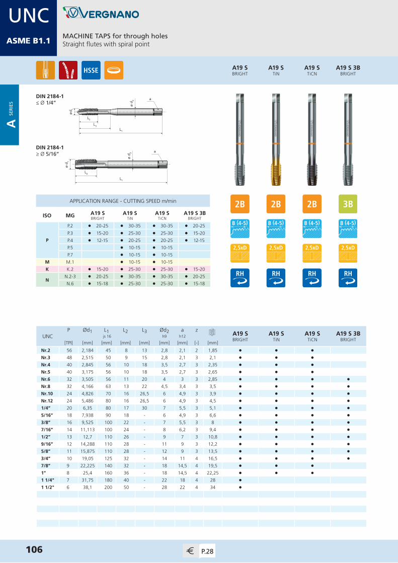
MDIN 13
ø d 2
L1
L2
L3
ø d1
a
ø d 1
L1
L2
ø d 2 a
APPLICATION RANGE - CUTTING SPEED m/min
ISO MG A19 SBRIGHT
A19 STiN
A19 STiCN
A19 S 3B BRIGHT
P
P.2 l 20-25 l 30-35 l 30-35 l 20-25
P.3 l 15-20 l 25-30 l 25-30 l 15-20
P.4 l 12-15 l 20-25 l 20-25 l 12-15
P.5 l 10-15 l 10-15
P.7 l 10-15 l 10-15
M M.1 l 10-15 l 10-15
K K.2 l 15-20 l 25-30 l 25-30 l 15-20
NN.2-3 l 20-25 l 30-35 l 30-35 l 20-25
N.6 l 15-18 l 25-30 l 25-30 l 15-18
A19 S 3B BRIGHT
A19 STiCN
A19 STiN
A19 SBRIGHT
MACHINE TAPS for through holesStraight flutes with spiral point
106 P.28
DIN 2184-1≤ Ø 1/4”
DIN 2184-1≥ Ø 5/16”
P Ød1 L1 L2 L3 Ød2 a zA19 SBRIGHT
A19 STiN
A19 STiCN
A19 S 3B BRIGHT
UNC js 16 h9 h12
[TPI] [mm] [mm] [mm] [mm] [mm] [mm] [-] [mm]
Nr.2 56 2,184 45 8 13 2,8 2,1 2 1,85 • • •Nr.3 48 2,515 50 9 15 2,8 2,1 3 2,1 • • •Nr.4 40 2,845 56 10 18 3,5 2,7 3 2,35 • • •Nr.5 40 3,175 56 10 18 3,5 2,7 3 2,65 • • •Nr.6 32 3,505 56 11 20 4 3 3 2,85 • • • •Nr.8 32 4,166 63 13 22 4,5 3,4 3 3,5 • • • •Nr.10 24 4,826 70 16 26,5 6 4,9 3 3,9 • • • •Nr.12 24 5,486 80 16 26,5 6 4,9 3 4,5 • • • •1/4” 20 6,35 80 17 30 7 5,5 3 5,1 • • • •5/16” 18 7,938 90 18 - 6 4,9 3 6,6 • • • •3/8” 16 9,525 100 22 - 7 5,5 3 8 • • • •7/16” 14 11,113 100 24 - 8 6,2 3 9,4 • • • • 1/2” 13 12,7 110 26 - 9 7 3 10,8 • • • •9/16” 12 14,288 110 28 - 11 9 3 12,2 • • • •5/8” 11 15,875 110 28 - 12 9 3 13,5 • • • •3/4” 10 19,05 125 32 - 14 11 4 16,5 • • • •7/8” 9 22,225 140 32 - 18 14,5 4 19,5 • • •1” 8 25,4 160 36 - 18 14,5 4 22,25 • • •1 1/4" 7 31,75 180 40 - 22 18 4 28 •1 1/2" 6 38,1 200 50 - 28 22 4 34 •
UNCASME B1.1
A SE
RIE
S
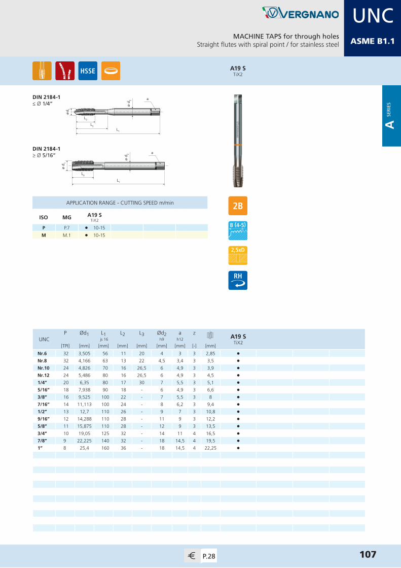
MDIN 13
ø d 2
L1
L2
L3
ø d1
a
ø d 1
L1
L2
ø d 2 a
APPLICATION RANGE - CUTTING SPEED m/min
ISO MG A19 STiX2
P P.7 l 10-15
M M.1 l 10-15
A19 STiX2
MACHINE TAPS for through holesStraight flutes with spiral point / for stainless steel
107P.28
P Ød1 L1 L2 L3 Ød2 a zA19 S
TiX2UNC js 16 h9 h12
[TPI] [mm] [mm] [mm] [mm] [mm] [mm] [-] [mm]
Nr.6 32 3,505 56 11 20 4 3 3 2,85 •Nr.8 32 4,166 63 13 22 4,5 3,4 3 3,5 •Nr.10 24 4,826 70 16 26,5 6 4,9 3 3,9 •Nr.12 24 5,486 80 16 26,5 6 4,9 3 4,5 •1/4” 20 6,35 80 17 30 7 5,5 3 5,1 •5/16” 18 7,938 90 18 - 6 4,9 3 6,6 •3/8” 16 9,525 100 22 - 7 5,5 3 8 •7/16” 14 11,113 100 24 - 8 6,2 3 9,4 • 1/2” 13 12,7 110 26 - 9 7 3 10,8 •9/16” 12 14,288 110 28 - 11 9 3 12,2 •5/8” 11 15,875 110 28 - 12 9 3 13,5 •3/4” 10 19,05 125 32 - 14 11 4 16,5 •7/8” 9 22,225 140 32 - 18 14,5 4 19,5 •1” 8 25,4 160 36 - 18 14,5 4 22,25 •
DIN 2184-1≤ Ø 1/4”
DIN 2184-1≥ Ø 5/16”
UNCASME B1.1
A SE
RIE
S

MDIN 13
ø d 2
L1
L2
L3
ø d 1
a
ø d 1
L1
L2
ø d 2 a
APPLICATION RANGE - CUTTING SPEED m/min
ISO MG A33BRIGHT
A33TiN
A33 3BBRIGHT
P
P.1 l 18-20 l 30-35 l 18-20
P.2 l 15-18 l 25-30 l 15-18
P.3 l 12-15 l 20-25 l 12-15
P.4 l 10-12 l 15-20 l 10-12
P.5 l 5-10
K K.2 l 12-15 l 20-25 l 12-15
N
N.1 l 18-20 l 18-20
N.2-3 l 15-18 l 25-30 l 15-18
N.5 l 15-18 l 15-18
N.6 l 12-15 l 20-25 l 12-15
A33 3BBRIGHT
A33TiN
A33BRIGHT
MACHINE TAPS for blind holes15° spiral flutes
108 P.29
P Ød1 L1 L2 L3 Ød2 a zA33
BRIGHTA33TiN
A33 3BBRIGHT
UNC js 16 h9 h12
[TPI] [mm] [mm] [mm] [mm] [mm] [mm] [-] [mm]
Nr.2 56 2,184 45 8 13 2,8 2,1 3 1,85 • •Nr.3 48 2,515 50 9 15 2,8 2,1 3 2,1 • •Nr.4 40 2,845 56 10 18 3,5 2,7 3 2,35 • •Nr.5 40 3,175 56 10 18 3,5 2,7 3 2,65 • •Nr.6 32 3,505 56 11 20 4 3 3 2,85 • • •Nr.8 32 4,166 63 13 20 4,5 3,4 3 3,5 • • •Nr.10 24 4,826 70 16 26,5 6 4,9 3 3,9 • • •Nr.12 24 5,486 80 16 29 6 4,9 3 4,5 • • •1/4” 20 6,35 80 17 30 7 5,5 3 5,1 • • •5/16” 18 7,938 90 18 - 6 4,9 3 6,6 • • •3/8” 16 9,525 100 22 - 7 5,5 3 8 • • •7/16” 14 11,113 100 24 - 8 6,2 3 9,4 • • • 1/2” 13 12,7 110 26 - 9 7 3 10,8 • • •9/16” 12 14,288 110 28 - 11 9 3 12,2 • • •5/8” 11 15,875 110 28 - 12 9 3 13,5 • • •3/4” 10 19,05 125 32 - 14 11 4 16,5 • • •7/8” 9 22,225 140 32 - 18 14,5 4 19,5 • •1” 8 25,4 160 36 - 18 14,5 4 22,25 • •1 1/8” 7 28,575 180 40 - 22 18 4 25 •1 1/4” 7 31,75 180 40 - 22 18 4 28 •1 3/8” 6 34,925 200 50 - 28 22 4 30,75 •1 1/2” 6 38,1 200 50 - 28 22 4 34 •
DIN 2184-1≤ Ø 1/4”
DIN 2184-1≥ Ø 5/16”
UNCASME B1.1
A SE
RIE
S

MDIN 13
ø d 2
L1
L2
L3
ø d 1
a
APPLICATION RANGE - CUTTING SPEED m/min
ISO MG A60 SBRIGHT
A60 STiN
A60 STiCN
A60 STiX2
P
P.2 l 15-20 l 25-30 l 25-30
P.3 l 12-15 l 20-25 l 20-25
P.4 l 10-12 l 15-20 l 15-20
P.5 l 5-10 l 5-10
P.7 l 8-10 l 8-10 l 8-10
MM.1 l 8-10 l 8-10 l 8-10
M.2 l 5-7
K K.2 l 12-15 l 20-25 l 20-25
NN.3 l 15-18 l 25-30 l 25-30
N.6 l 15-18 l 25-30 l 25-30
A60 STiX2
A60 STiCN
A60 STiN
A60 SBRIGHT
MACHINE TAPS for blind holes40° spiral flutes / back tapered
109P.29
P Ød1 L1 L2 L3 Ød2 a zA60 SBRIGHT
A60 STiN
A60 STiCN
A60 STiX2
UNC js 16 h9 h12
[TPI] [mm] [mm] [mm] [mm] [mm] [mm] [-] [mm]
Nr.2 56 2,184 45 6 13 2,8 2,1 3 1,85 • • • •Nr.3 48 2,515 50 6 15 2,8 2,1 3 2,1 • • • •Nr.4 40 2,845 56 6,5 21 3,5 2,7 3 2,35 • • • •Nr.5 40 3,175 56 6,5 21 3,5 2,7 3 2,65 • • • •Nr.6 32 3,505 56 7,5 22,5 4 3 3 2,85 • • • •Nr.8 32 4,166 63 7,5 26 4,5 3,4 3 3,5 • • • •Nr.10 24 4,826 70 10 28,5 6 4,9 3 3,9 • • • •Nr.12 24 5,486 80 10 28,5 6 4,9 3 4,5 • • • •1/4” 20 6,35 80 11,5 32 7 5,5 3 5,1 • • • •5/16” 18 7,938 90 13 - 6 4,9 3 6,6 • • • •3/8” 16 9,525 100 14 - 7 5,5 3 8 • • • •7/16” 14 11,113 100 17 - 8 6,2 3 9,4 • • • • 1/2” 13 12,7 110 19 - 9 7 4 10,8 • • • •9/16” 12 14,288 110 21 - 11 9 4 12,2 • • • •5/8” 11 15,875 110 22,5 - 12 9 4 13,5 • • • •3/4” 10 19,05 125 26 - 14 11 4 16,5 • • • •7/8” 9 22,225 140 30 - 18 14,5 4 19,5 • • • •1” 8 25,4 160 36,5 - 18 14,5 4 22,25 • • • •1 1/4" 7 31,75 180 42 - 22 18 5 28 •1 1/2" 6 38,1 200 49 - 28 22 5 34 •
DIN 2184-1≤ Ø 1/4”
DIN 2184-1≥ Ø 5/16”
UNCASME B1.1
A SE
RIE
S

MDIN 13
ø d 2
L1
L2
L3
ø d 1
a
ø d 1
L1
L2
ø d 2 a
APPLICATION RANGE - CUTTING SPEED m/min
ISO MG A65BRIGHT
NN.1-2 l 12-15
N.5-6 l 10-15
SS.1 l 6-8
S.3 l 6-8
A65BRIGHT
MACHINE TAPS for blind holesTwo 40° spiral flutes / for light alloys
110 P.30
DIN 2184-1≤ Ø 1/4”
DIN 2184-1≥ Ø 5/16”
P Ød1 L1 L2 L3 Ød2 a zA65
BRIGHTUNC js 16 h9 h12
[TPI] [mm] [mm] [mm] [mm] [mm] [mm] [-] [mm]
Nr.3 48 2,515 50 9 15 2,8 2,1 2 2,1 •Nr.4 40 2,845 56 10 18 3,5 2,7 2 2,35 •Nr.5 40 3,175 56 10 18 3,5 2,7 2 2,65 •Nr.6 32 3,505 56 11 20 4 3 2 2,85 •Nr.8 32 4,166 63 13 20 4,5 3,4 2 3,5 •Nr.10 24 4,826 70 16 26,5 6 4,9 2 3,9 •Nr.12 24 5,486 80 16 29 6 4,9 2 4,5 •1/4” 20 6,35 80 17 30 7 5,5 2 5,1 •5/16” 18 7,938 90 18 - 6 4,9 2 6,6 •3/8” 16 9,525 100 22 - 7 5,5 2 8 •
UNCASME B1.1
A SE
RIE
S

MDIN 13
HAND TAPS for blind and through holesIn sets of two pieces
111P.30
ø d 2
L1
L2
L3
ø d 1
a
ø d 1
L2
ø d 2 a
L1
P Ød1 L1 L2 L3 Ød2 a zA8
ROUGHINGA8
FINISHINGA8SET
UNF js 16 h9 h12
[TPI] [mm] [mm] [mm] [mm] [mm] [mm] [-] [mm]
Nr.2 64 2,184 36 9 15 2,8 2,1 3 1,85 • • •Nr.3 56 2,515 40 9 15 2,8 2,1 3 2,15 • • •Nr.4 48 2,845 40 10 18 3,5 2,7 3 2,4 • • •Nr.5 44 3,175 40 10 18 3,5 2,7 3 2,7 • • •Nr.6 40 3,505 45 11 20 4 3 3 2,95 • • •Nr.8 36 4,166 45 12 21 4,5 3,4 3 3,5 • • •Nr.10 32 4,826 50 14 23 6 4,9 3 4,1 • • •Nr.12 28 5,486 56 16 28 6 4,9 3 4,6 • • •1/4” 28 6,35 56 16 28 6 4,9 3 5,5 • • •5/16” 24 7,938 63 18 - 6 4,9 3 6,9 • • •3/8” 24 9,525 63 18 - 7 5,5 3 8,5 • • •7/16” 20 11,113 70 20 - 8 6,2 3 9,9 • • •1/2” 20 12,7 70 20 - 9 7 4 11,5 • • •9/16” 18 14,288 70 22 - 11 9 4 12,9 • • •5/8” 18 15,875 70 22 - 12 9 4 14,5 • • •3/4” 16 19,05 80 22 - 14 11 4 17,5 • • •7/8” 14 22,225 80 22 - 18 14,5 4 20,4 • • •1” 12 25,4 90 22 - 18 14,5 4 23,25 • • •1 1/8” 12 28,575 90 22 - 22 18 4 26,5 • • •1 1/4” 12 31,75 90 22 - 22 18 4 29,5 • • •
A8SET
A8FINISHING
A8ROUGHING
DIN 2184-2≤ Ø 1/4”
DIN 2184-2≥ Ø 5/16”
APPLICATION RANGE - CUTTING SPEED m/min
ISO MG A8ROUGHING
A8FINISHING
A8SET
PP.1-4 l l l
P.7 l l l
K K.2 l l l
NN.1-3 l l l
N.5-7 l l l
UNFASME B1.1
A SE
RIE
S

MDIN 13
112 P.31
ø d 2
L1
L2
L3
ø d1
a
ø d 1
L1
L2
ø d 2 a
APPLICATION RANGE - CUTTING SPEED m/min
ISO MG A28 FCBRIGHT
A28 FCTiN
A28 FPBRIGHT
A28 FPTiN
P
P.1 l 20-25 l 20-25
P.2 l 10-12 l 15-20 l 10-12 l 15-20
P.3 l 8-10 l 12-15 l 8-10 l 12-15
K K.2 l 8-10 l 12-15 l 8-10 l 12-15
NN.1 l 20-25 l 20-25
N.5 l 15-20 l 15-20
P Ød1 L1 L2 L3 Ød2 a zA28 FCBRIGHT
A28 FCTiN
A28 FPBRIGHT
A28 FPTiN
UNF js 16 h9 h12
[TPI] [mm] [mm] [mm] [mm] [mm] [mm] [-] [mm]
Nr.2 64 2,184 45 9 13 2,8 2,1 3 1,85 • • • •Nr.3 56 2,515 50 9 15 2,8 2,1 3 2,15 • • • •Nr.4 48 2,845 56 10 18 3,5 2,7 3 2,4 • • • •Nr.5 44 3,175 56 10 18 3,5 2,7 3 2,7 • • • •Nr.6 40 3,505 56 11 20 4 3 3 2,95 • • • •Nr.8 36 4,166 63 12 21 4,5 3,4 3 3,5 • • • •Nr.10 32 4,826 70 14 24,5 6 4,9 3 4,1 • • • •Nr.12 28 5,486 80 16 26,5 6 4,9 3 4,6 • • • •1/4” 28 6,35 80 16 30 7 5,5 3 5,5 • • • •5/16” 24 7,938 90 18 - 6 4,9 3 6,9 • • • •3/8” 24 9,525 90 18 - 7 5,5 3 8,5 • • • •7/16” 20 11,113 100 20 - 8 6,2 3 9,9 • • • • 1/2” 20 12,7 100 22 - 9 7 3 11,5 • • • •9/16” 18 14,288 100 22 - 11 9 3 12,9 • • • •5/8” 18 15,875 100 22 - 12 9 3 14,5 • • • •3/4” 16 19,05 110 25 - 14 11 4 17,5 • • • •7/8” 14 22,225 125 25 - 18 14,5 4 20,4 • • • •1” 12 25,4 140 28 - 18 14,5 4 23,25 • • • •1 1/8” 12 28,575 150 28 - 22 18 4 26,5 • • 1 1/4” 12 31,75 150 28 - 22 18 4 29,5 • •1 3/8” 12 34,925 170 30 - 28 22 4 32,75 • • 1 1/2” 12 38,1 170 30 - 28 22 5 36 • •
A28 FPTiN
A28 FPBRIGHT
A28 FCTiN
A28 FCBRIGHT
MACHINE TAPS for blind holes (FC) and for through holes (FP)Straight flutes
DIN 2184-1≤ Ø 1/4”
DIN 2184-1≥ Ø 5/16”
UNFASME B1.1
A SE
RIE
S

MDIN 13
APPLICATION RANGE - CUTTING SPEED m/min
ISO MG A50NITRIDED
A50TiCN
K K.1 l 15-20 l 40-45
N
N.4 l 15-20 l 40-45
N.7 l 15-20 l 40-45
N.9-10 l 20-25 l 45-50
A50TiCN
A50NITRIDED
MACHINE TAPS for blind and through holesStraight flutes / for cast iron
113P.31
ø d 2
L1
L2
L3
ø d1
a
ø d 1
L1
L2
ø d 2 a
DIN 2184-1≤ Ø 1/4”
DIN 2184-1≥ Ø 5/16”
P Ød1 L1 L2 L3 Ød2 a zA50
NITRIDEDA50TiCN
UNF js 16 h9 h12
[TPI] [mm] [mm] [mm] [mm] [mm] [mm] [-] [mm]
Nr.8 36 4,166 63 12 21 4,5 3,4 3 3,5 • •Nr.10 32 4,826 70 14 24,5 6 4,9 3 4,1 • •Nr.12 28 5,486 80 16 26,5 6 4,9 3 4,6 • •1/4” 28 6,35 80 16 30 7 5,5 3 5,5 • •5/16” 24 7,938 90 18 - 6 4,9 4 6,9 • •3/8” 24 9,525 90 18 - 7 5,5 4 8,5 • •7/16” 20 11,113 100 20 - 8 6,2 4 9,9 • • 1/2” 20 12,7 100 22 - 9 7 4 11,5 • •9/16” 18 14,288 100 22 - 11 9 4 12,9 • •5/8” 18 15,875 100 22 - 12 9 4 14,5 • •3/4” 16 19,05 110 25 - 14 11 4 17,5 • •7/8” 14 22,225 125 25 - 18 14,5 4 20,4 • •1” 12 25,4 140 28 - 18 14,5 5 23,25 • •1 1/8” 12 28,575 150 28 - 22 18 5 26,5 •1 1/4” 12 31,75 150 28 - 22 18 5 29,5 • 1 3/8” 12 34,925 170 30 - 28 22 5 32,75 •1 1/2” 12 38,1 170 30 - 28 22 5 36 •
UNFASME B1.1
A SE
RIE
S
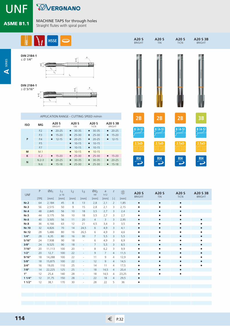
MDIN 13
114 P.32
ø d 2
L1
L2
L3
ø d1
a
ø d 1
L1
L2
ø d 2 a
APPLICATION RANGE - CUTTING SPEED m/min
ISO MG A20 SBRIGHT
A20 STiN
A20 STiCN
A20 S 3BBRIGHT
P
P.2 l 20-25 l 30-35 l 30-35 l 20-25
P.3 l 15-20 l 25-30 l 25-30 l 15-20
P.4 l 12-15 l 20-25 l 20-25 l 12-15
P.5 l 10-15 l 10-15
P.7 l 10-15 l 10-15
M M.1 l 10-15 l 10-15
K K.2 l 15-20 l 25-30 l 25-30 l 15-20
NN.2-3 l 20-25 l 30-35 l 30-35 l 20-25
N.6 l 15-18 l 25-30 l 25-30 l 15-18
P Ød1 L1 L2 L3 Ød2 a zA20 SBRIGHT
A20 STiN
A20 STiCN
A20 S 3BBRIGHT
UNF js 16 h9 h12
[TPI] [mm] [mm] [mm] [mm] [mm] [mm] [-] [mm]
Nr.2 64 2,184 45 8 13 2,8 2,1 2 1,85 • • •Nr.3 56 2,515 50 9 15 2,8 2,1 3 2,15 • • •Nr.4 48 2,845 56 10 18 3,5 2,7 3 2,4 • • •Nr.5 44 3,175 56 10 18 3,5 2,7 3 2,7 • • •Nr.6 40 3,505 56 11 20 4 3 3 2,95 • • • •Nr.8 36 4,166 63 12 21 4,5 3,4 3 3,5 • • • •Nr.10 32 4,826 70 14 24,5 6 4,9 3 4,1 • • • •Nr.12 28 5,486 80 16 26,5 6 4,9 3 4,6 • • • •1/4” 28 6,35 80 16 30 7 5,5 3 5,5 • • • •5/16” 24 7,938 90 18 - 6 4,9 3 6,9 • • • •3/8” 24 9,525 90 18 - 7 5,5 3 8,5 • • • •7/16” 20 11,113 100 20 - 8 6,2 3 9,9 • • • • 1/2” 20 12,7 100 22 - 9 7 4 11,5 • • • •9/16” 18 14,288 100 22 - 11 9 4 12,9 • • • •5/8” 18 15,875 100 22 - 12 9 4 14,5 • • • •3/4” 16 19,05 110 25 - 14 11 4 17,5 • • • •7/8” 14 22,225 125 25 - 18 14,5 4 20,4 • • •1” 12 25,4 140 28 - 18 14,5 4 23,25 • • •1 1/4" 12 31,75 150 28 - 22 18 4 29,5 •1 1/2" 12 38,1 170 30 - 28 22 5 36 •
A20 S 3BBRIGHT
A20 STiCN
A20 STiN
A20 SBRIGHT
MACHINE TAPS for through holesStraight flutes with spiral point
DIN 2184-1≤ Ø 1/4”
DIN 2184-1≥ Ø 5/16”
UNFASME B1.1
A SE
RIE
S
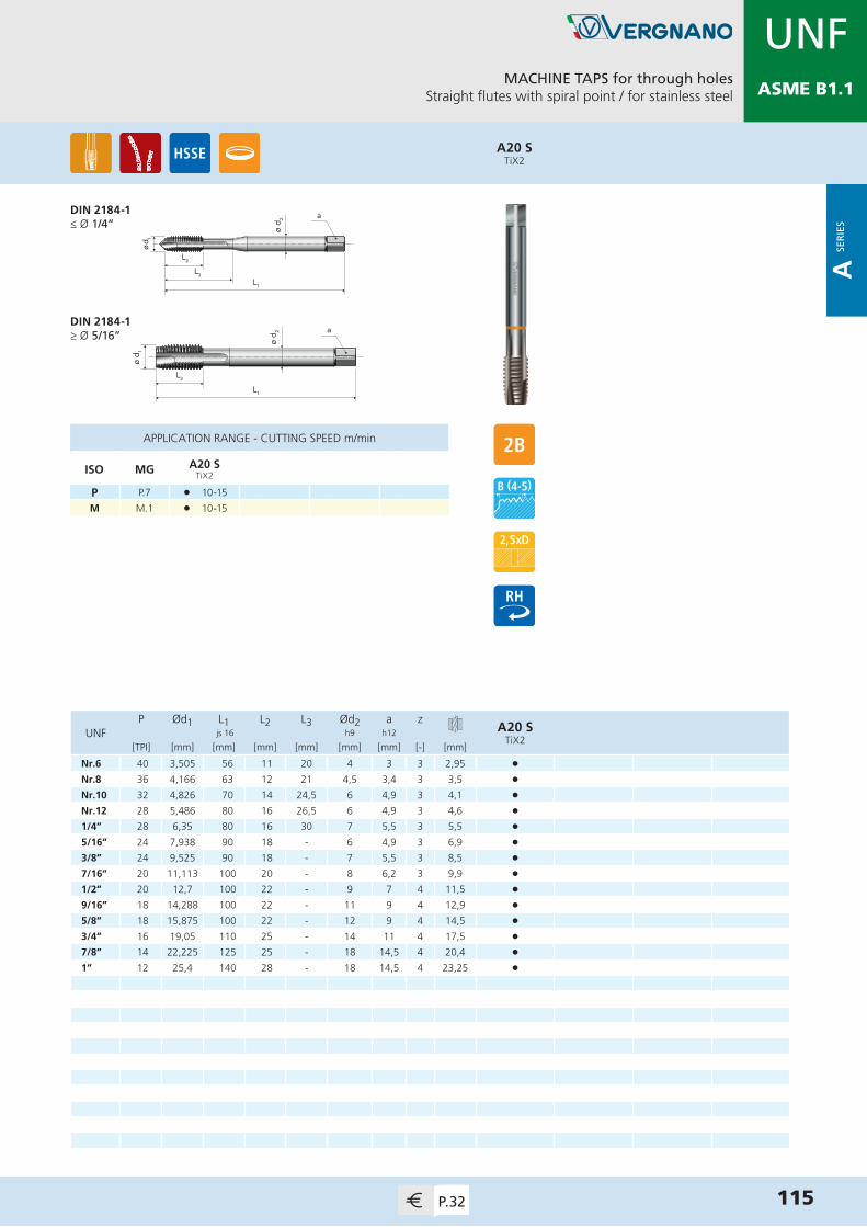
MDIN 13
MACHINE TAPS for through holesStraight flutes with spiral point / for stainless steel
115P.32
ø d 2
L1
L2
L3
ø d1
a
ø d 1
L1
L2
ø d 2 a
APPLICATION RANGE - CUTTING SPEED m/min
ISO MG A20 STiX2
P P.7 l 10-15
M M.1 l 10-15
P Ød1 L1 L2 L3 Ød2 a zA20 S
TiX2UNF js 16 h9 h12
[TPI] [mm] [mm] [mm] [mm] [mm] [mm] [-] [mm]
Nr.6 40 3,505 56 11 20 4 3 3 2,95 •Nr.8 36 4,166 63 12 21 4,5 3,4 3 3,5 •Nr.10 32 4,826 70 14 24,5 6 4,9 3 4,1 •Nr.12 28 5,486 80 16 26,5 6 4,9 3 4,6 •1/4” 28 6,35 80 16 30 7 5,5 3 5,5 •5/16” 24 7,938 90 18 - 6 4,9 3 6,9 •3/8” 24 9,525 90 18 - 7 5,5 3 8,5 •7/16” 20 11,113 100 20 - 8 6,2 3 9,9 • 1/2” 20 12,7 100 22 - 9 7 4 11,5 •9/16” 18 14,288 100 22 - 11 9 4 12,9 •5/8” 18 15,875 100 22 - 12 9 4 14,5 •3/4” 16 19,05 110 25 - 14 11 4 17,5 •7/8” 14 22,225 125 25 - 18 14,5 4 20,4 •1” 12 25,4 140 28 - 18 14,5 4 23,25 •
A20 STiX2
DIN 2184-1≤ Ø 1/4”
DIN 2184-1≥ Ø 5/16”
UNFASME B1.1
A SE
RIE
S
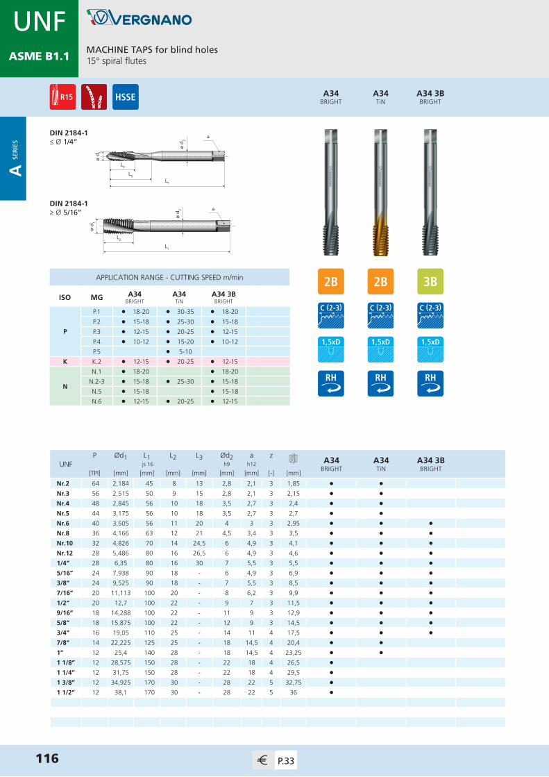
MDIN 13
ø d 2
L2
ø d 1
a
L1
L3
ø d 1
L1
L2
ø d 2 a
A34 3BBRIGHT
A34TiN
A34BRIGHT
MACHINE TAPS for blind holes15° spiral flutes
116 P.33
P Ød1 L1 L2 L3 Ød2 a zA34
BRIGHTA34TiN
A34 3BBRIGHT
UNF js 16 h9 h12
[TPI] [mm] [mm] [mm] [mm] [mm] [mm] [-] [mm]
Nr.2 64 2,184 45 8 13 2,8 2,1 3 1,85 • •Nr.3 56 2,515 50 9 15 2,8 2,1 3 2,15 • •Nr.4 48 2,845 56 10 18 3,5 2,7 3 2,4 • •Nr.5 44 3,175 56 10 18 3,5 2,7 3 2,7 • •Nr.6 40 3,505 56 11 20 4 3 3 2,95 • • •Nr.8 36 4,166 63 12 21 4,5 3,4 3 3,5 • • •Nr.10 32 4,826 70 14 24,5 6 4,9 3 4,1 • • •Nr.12 28 5,486 80 16 26,5 6 4,9 3 4,6 • • •1/4” 28 6,35 80 16 30 7 5,5 3 5,5 • • •5/16” 24 7,938 90 18 - 6 4,9 3 6,9 • • •3/8” 24 9,525 90 18 - 7 5,5 3 8,5 • • •7/16” 20 11,113 100 20 - 8 6,2 3 9,9 • • •1/2” 20 12,7 100 22 - 9 7 3 11,5 • • •9/16” 18 14,288 100 22 - 11 9 3 12,9 • • •5/8” 18 15,875 100 22 - 12 9 3 14,5 • • •3/4” 16 19,05 110 25 - 14 11 4 17,5 • • •7/8” 14 22,225 125 25 - 18 14,5 4 20,4 • •1” 12 25,4 140 28 - 18 14,5 4 23,25 • •1 1/8” 12 28,575 150 28 - 22 18 4 26,5 •1 1/4” 12 31,75 150 28 - 22 18 4 29,5 •1 3/8” 12 34,925 170 30 - 28 22 5 32,75 •1 1/2” 12 38,1 170 30 - 28 22 5 36 •
DIN 2184-1≤ Ø 1/4”
DIN 2184-1≥ Ø 5/16”
APPLICATION RANGE - CUTTING SPEED m/min
ISO MG A34BRIGHT
A34TiN
A34 3BBRIGHT
P
P.1 l 18-20 l 30-35 l 18-20
P.2 l 15-18 l 25-30 l 15-18
P.3 l 12-15 l 20-25 l 12-15
P.4 l 10-12 l 15-20 l 10-12
P.5 l 5-10
K K.2 l 12-15 l 20-25 l 12-15
N
N.1 l 18-20 l 18-20
N.2-3 l 15-18 l 25-30 l 15-18
N.5 l 15-18 l 15-18
N.6 l 12-15 l 20-25 l 12-15
UNFASME B1.1
A SE
RIE
S

MDIN 13
ø d 2
L1
L2
L3
ø d 1
a
ø d 1
L2
ø d 2 a
L1
A61 STiX2
A61 STiCN
A61 STiN
A61 SBRIGHT
MACHINE TAPS for blind holes40° spiral flutes / back tapered
117P.33
P Ød1 L1 L2 L3 Ød2 a zA61 SBRIGHT
A61 STiN
A61 STiCN
A61 STiX2
UNF js 16 h9 h12
[TPI] [mm] [mm] [mm] [mm] [mm] [mm] [-] [mm]
Nr.2 64 2,184 45 5,5 13 2,8 2,1 3 1,85 • • •Nr.3 56 2,515 50 6 18 2,8 2,1 3 2,15 • • •Nr.4 48 2,845 56 6 18 3,5 2,7 3 2,4 • • •Nr.5 44 3,175 56 6 18 3,5 2,7 3 2,7 • • •Nr.6 40 3,505 56 6,5 22 4 3 3 2,95 • • • •Nr.8 36 4,166 63 7 26,5 4,5 3,4 3 3,5 • • • •Nr.10 32 4,826 70 8 29 6 4,9 3 4,1 • • • •Nr.12 28 5,486 80 9 29,5 6 4,9 3 4,6 • • • •1/4” 28 6,35 80 10 32 7 5,5 3 5,5 • • • •5/16” 24 7,938 90 11 - 6 4,9 3 6,9 • • • •3/8” 24 9,525 90 12 - 7 5,5 3 8,5 • • • •7/16” 20 11,113 100 13,5 - 8 6,2 3 9,9 • • • • 1/2” 20 12,7 100 14,5 - 9 7 4 11,5 • • • •9/16” 18 14,288 100 15,5 - 11 9 4 12,9 • • • •5/8” 18 15,875 100 16 - 12 9 4 14,5 • • • •3/4” 16 19,05 110 18 - 14 11 4 17,5 • • • •7/8” 14 22,225 125 23,5 - 18 14,5 4 20,4 • • • •1” 12 25,4 140 26 - 18 14,5 4 23,25 • • • •1 1/4" 12 31,75 150 26 - 22 18 5 29,5 •1 1/2" 12 38,1 170 29 - 28 22 5 36 •
DIN 2184-1≤ Ø 1/4”
DIN 2184-1≥ Ø 5/16”
APPLICATION RANGE - CUTTING SPEED m/min
ISO MG A61 SBRIGHT
A61 STiN
A61 STiCN
A61 STiX2
P
P.2 l 15-20 l 25-30 l 25-30
P.3 l 12-15 l 20-25 l 20-25
P.4 l 10-12 l 15-20 l 15-20
P.5 l 5-10 l 5-10
P.7 l 8-10 l 8-10 l 8-10
MM.1 l 8-10 l 8-10 l 8-10
M.2 l 5-7
K K.2 l 12-15 l 20-25 l 20-25
NN.3 l 15-18 l 25-30 l 25-30
N.6 l 15-18 l 25-30 l 25-30
UNFASME B1.1
A SE
RIE
S

MDIN 13
ø d 2
L1
L2
L3
ø d 1
a
ø d 1
L1
L2
ø d 2 a
APPLICATION RANGE - CUTTING SPEED m/min
ISO MG A66BRIGHT
NN.1-2 l 12-15
N.5-6 l 10-15
SS.1 l 6-8
S.3 l 6-8
A66BRIGHT
MACHINE TAPS for blind holesTwo 40° spiral flutes / for light alloys
118 P.34
P Ød1 L1 L2 L3 Ød2 a zA66
BRIGHTUNF js 16 h9 h12
[TPI] [mm] [mm] [mm] [mm] [mm] [mm] [-] [mm]
Nr.2 64 2,184 45 8 13 2,8 2,1 2 1,85 •Nr.3 56 2,515 50 9 15 2,8 2,1 2 2,15 •Nr.4 48 2,845 56 10 18 3,5 2,7 2 2,4 •Nr.5 44 3,175 56 10 18 3,5 2,7 2 2,7 •Nr.6 40 3,505 56 11 20 4 3 2 2,95 •Nr.8 36 4,166 63 12 21 4,5 3,4 2 3,5 •Nr.10 32 4,826 70 14 24,5 6 4,9 2 4,1 •Nr.12 28 5,486 80 16 26,5 6 4,9 2 4,6 •1/4” 28 6,35 80 16 30 7 5,5 2 5,5 •5/16” 24 7,938 90 18 - 6 4,9 2 6,9 •3/8” 24 9,525 90 18 - 7 5,5 2 8,5 •
DIN 2184-1≤ Ø 1/4”
DIN 2184-1≥ Ø 5/16”
UNFASME B1.1
A SE
RIE
S

MDIN 13
ø d 1
L1
L2
ø d 2 a
A119TiN
A119BRIGHT
MACHINE TAPS for through holesStraight flutes with spiral point
NORM VERGNANO
119P.34
P Ød1 L1 L2 L3 Ød2 a zA119BRIGHT
A119TiN
8-UN js 16 h9 h12
[TPI] [mm] [mm] [mm] [mm] [mm] [mm] [-] [mm]
1 1/8” 8 28,575 180 40 - 22 18 4 25,4 • •1 1/4” 8 31,75 180 40 - 25 20 4 28,6 • •1 3/8” 8 34,925 200 50 - 28 22 4 31,8 • •1 1/2” 8 38,1 200 50 - 32 24 4 35 • •1 5/8” 8 41,275 200 50 - 32 24 5 38,1 • •1 3/4” 8 44,45 200 50 - 36 29 5 41,3 • •1 7/8” 8 47,625 225 60 - 36 29 5 44,5 • •2” 8 50,8 225 60 - 40 32 5 47,7 • •
APPLICATION RANGE - CUTTING SPEED m/min
ISO MG A119BRIGHT
A119TiN
P
P.2 l 20-25 l 30-35
P.3 l 15-20 l 25-30
P.4 l 12-15 l 20-25
P.5 l 10-15
P.7 l 10-15
M M.1 l 10-15
K K.2 l 15-20 l 25-30
NN.2-3 l 20-25 l 30-35
N.6 l 15-18 l 25-30
8-UNASME B1.1
A SE
RIE
S

MDIN 13
A160TiN
A160BRIGHT
MACHINE TAPS for blind holes40° spiral flutes / back tapered
120 P.34
P Ød1 L1 L2 L3 Ød2 a zA160BRIGHT
A160TiN
8-UN js 16 h9 h12
[TPI] [mm] [mm] [mm] [mm] [mm] [mm] [-] [mm]
1 1/8” 8 28,575 180 40 - 22 18 4 25,4 • •1 1/4” 8 31,75 180 41,5 - 25 20 4 28,6 • •1 3/8” 8 34,925 200 50 - 28 22 4 31,1 • •1 1/2” 8 38,1 200 50 - 32 24 5 35 • •1 5/8” 8 41,275 200 52 - 32 24 5 38,1 • •1 3/4” 8 44,45 200 52 - 36 29 5 41,3 • •1 7/8” 8 47,625 225 53,5 - 36 29 5 44,5 • •2” 8 50,8 225 61,5 - 40 32 5 47,7 • •
APPLICATION RANGE - CUTTING SPEED m/min
ISO MG A160BRIGHT
A160TiN
P
P.2 l 15-20 l 25-30
P.3 l 12-15 l 20-25
P.4 l 10-12 l 15-20
P.5 l 5-10
P.7 l 8-10
M M.1 l 8-10
K K.2 l 12-15 l 20-25
NN.3 l 15-18 l 25-30
N.6 l 15-18 l 25-30
NORM VERGNANO
8-UNASME B1.1
A SE
RIE
S

MDIN 13
HAND TAPS for blind and through holesIn sets of two pieces
121P.35
ø d 1
L1
ø d 2 a
L2
P Ød1 L1 L2 L3 Ød2 a zA5
ROUGHINGA5
FINISHINGA5SET
G js 16 h9 h12
[TPI] [mm] [mm] [mm] [mm] [mm] [mm] [-] [mm]
1/8” 28 9,728 63 18 - 7 5,5 3 8,8 • • •1/4” 19 13,157 70 20 - 11 9 4 11,8 • • •3/8” 19 16,662 70 20 - 12 9 4 15,25 • • •1/2” 14 20,955 80 22 - 16 12 4 19 • • •5/8” 14 22,911 80 22 - 18 14,5 4 21 • • •3/4” 14 26,441 90 22 - 20 16 4 24,5 • • •7/8” 14 30,201 90 22 - 22 18 4 28,25 • • •1” 11 33,249 100 25 - 25 20 4 30,75 • • •1 1/8” 11 37,897 125 32 - 28 22 5 35,5 • • •1 1/4” 11 41,91 125 32 - 32 24 5 39,5 • • •1 1/2” 11 47,803 140 32 - 36 29 6 45,25 • • •1 3/4” 11 53,746 140 36 - 40 32 6 51 • • • 2” 11 59,614 160 36 - 45 35 6 57 • • •
A5SET
A5FINISHING
A5ROUGHING
DIN 5157
APPLICATION RANGE - CUTTING SPEED m/min
ISO MG A5ROUGHING
A5FINISHING
A5SET
PP.1-4 l l l
P.7 l l l
K K.2 l l l
NN.1-3 l l l
N.5-7 l l l
GEN ISO 228
A SE
RIE
S

MDIN 13
ø d 1
L1
L2
ø d 2 a
APPLICATION RANGE - CUTTING SPEED m/min
ISO MG A26 FCBRIGHT
A26 FPBRIGHT
PP.2 l 10-12 l 10-12
P.3 l 8-10 l 8-10
K K.2 l 8-10 l 8-10
A26 FPBRIGHT
A26 FCBRIGHT
MACHINE TAPS for blind holes (FC) and for through holes (FP)Straight flutes
DIN 5156
122 P.35
P Ød1 L1 L2 L3 Ød2 a zA26 FCBRIGHT
A26 FPBRIGHT
G js 16 h9 h12
[TPI] [mm] [mm] [mm] [mm] [mm] [mm] [-] [mm]
1/8” 28 9,728 90 18 - 7 5,5 3 8,8 • •1/4” 19 13,157 100 22 - 11 9 3 11,8 • •3/8” 19 16,662 100 22 - 12 9 3 15,25 • •1/2” 14 20,955 125 25 - 16 12 4 19 • •5/8” 14 22,911 125 25 - 18 14,5 4 21 • •3/4” 14 26,441 140 28 - 20 16 4 24,5 • •7/8” 14 30,201 150 28 - 22 18 4 28,25 • •1” 11 33,249 160 30 - 25 20 4 30,75 • •1 1/8” 11 37,897 170 30 - 28 22 5 35,5 • •1 1/4” 11 41,91 170 30 - 32 24 5 39,5 • •1 1/2” 11 47,803 190 32 - 36 29 6 45,25 • •1 3/4” 11 53,746 190 32 - 40 32 6 51 • • 2” 11 59,614 220 40 - 45 35 6 57 • •2 1/2” 11 75,184 250 50 - 45 35 8 72,8 • •
GEN ISO 228
A SE
RIE
S

MDIN 13
ø d 1
L1
L2
ø d 2 a
APPLICATION RANGE - CUTTING SPEED m/min
ISO MG A48NITRIDED
A48TiCN
K K.1 l 15-20 l 40-45
N
N.4 l 15-20 l 40-45
N.7 l 15-20 l 40-45
N.9-10 l 20-25 l 45-50
A48TiCN
A48NITRIDED
MACHINE TAPS for blind and through holesStraight flutes / for cast iron
DIN 5156
123P.35
P Ød1 L1 L2 L3 Ød2 a zA48
NITRIDEDA48TiCN
G js 16 h9 h12
[TPI] [mm] [mm] [mm] [mm] [mm] [mm] [-] [mm]
1/8” 28 9,728 90 18 - 7 5,5 4 8,8 • •1/4” 19 13,157 100 22 - 11 9 4 11,8 • •3/8” 19 16,662 100 22 - 12 9 4 15,25 • •1/2” 14 20,955 125 25 - 16 12 4 19 • •5/8” 14 22,911 125 25 - 18 14,5 4 21 • •3/4” 14 26,441 140 28 - 20 16 5 24,5 • •7/8” 14 30,201 150 28 - 22 18 5 28,25 • •1” 11 33,249 160 30 - 25 20 5 30,75 • •1 1/8” 11 37,897 170 30 - 28 22 6 35,5 •1 1/4” 11 41,91 170 30 - 32 24 6 39,5 •1 1/2” 11 47,803 190 32 - 36 29 6 45,25 •
GEN ISO 228
A SE
RIE
S

MDIN 13
ø d 1
L1
L2
ø d 2 a
A18 STiX2
A18 STiCN
A18 SVAP
A18 SBRIGHT
MACHINE TAPS for through holesStraight flutes with spiral point
DIN 5156
124 P.36
P Ød1 L1 L2 L3 Ød2 a zA18 SBRIGHT
A18 SVAP
A18 STiCN
A18 STiX2
G js 16 h9 h12
[TPI] [mm] [mm] [mm] [mm] [mm] [mm] [-] [mm]
1/8” 28 9,728 90 18 - 7 5,5 4 8,8 • • • •1/4” 19 13,157 100 22 - 11 9 4 11,8 • • • •3/8” 19 16,662 100 22 - 12 9 4 15,25 • • • •1/2” 14 20,955 125 25 - 16 12 4 19 • • • •5/8” 14 22,911 125 25 - 18 14,5 4 21 • • • •3/4” 14 26,441 140 28 - 20 16 4 24,5 • • • •7/8” 14 30,201 150 28 - 22 18 4 28,25 • • • •1” 11 33,249 160 30 - 25 20 4 30,75 • • • •1 1/8” 11 37,897 170 30 - 28 22 5 35,5 •1 1/4” 11 41,91 170 30 - 32 24 5 39,5 •1 1/2” 11 47,803 190 32 - 36 29 5 45,25 •
APPLICATION RANGE - CUTTING SPEED m/min
ISO MG A18 SBRIGHT
A18 SVAP
A18 STiCN
A18 STiX2
P
P.2 l 20-25 l 20-25 l 30-35
P.3 l 15-20 l 15-20 l 25-30
P.4 l 12-15 l 12-15 l 20-25
P.5 l 10-15
P.7 l 10-15 l 10-15
M M.1 l 10-15 l 10-15
K K.2 l 15-20 l 15-20 l 25-30
NN.2-3 l 20-25 l 20-25 l 30-35
N.6 l 15-18 l 15-18 l 25-30
GEN ISO 228
A SE
RIE
S

MDIN 13
ø d 1
L1
L2
ø d 2 a
A32TiN
A32BRIGHT
MACHINE TAPS for blind holes15° spiral flutes
DIN 5156
125P.36
P Ød1 L1 L2 L3 Ød2 a zA32
BRIGHTA32TiN
G js 16 h9 h12
[TPI] [mm] [mm] [mm] [mm] [mm] [mm] [-] [mm]
1/8” 28 9,728 90 18 - 7 5,5 3 8,8 • •1/4” 19 13,157 100 22 - 11 9 3 11,8 • •3/8” 19 16,662 100 22 - 12 9 3 15,25 • •1/2” 14 20,955 125 25 - 16 12 4 19 • •5/8” 14 22,911 125 25 - 18 14,5 4 21 • •3/4” 14 26,441 140 28 - 20 16 4 24,5 • •7/8” 14 30,201 150 28 - 22 18 4 28,25 • •1” 11 33,249 160 30 - 25 20 4 30,75 • •1 1/8” 11 37,897 170 30 - 28 22 5 35,5 •1 1/4” 11 41,91 170 30 - 32 24 5 39,5 •1 1/2” 11 47,803 190 32 - 36 29 6 45,25 •1 3/4” 11 53,746 190 32 - 40 32 6 51 • 2” 11 59,614 220 40 - 45 35 6 57 •2 1/2” 11 75,184 250 50 - 45 35 8 72,8 •
APPLICATION RANGE - CUTTING SPEED m/min
ISO MG A32BRIGHT
A32TiN
P
P.1 l 18-20 l 30-35
P.2 l 15-18 l 25-30
P.3 l 12-15 l 20-25
P.4 l 10-12 l 15-20
P.5 l 5-10
K K.2 l 12-15 l 20-25
N
N.1 l 18-20
N.2-3 l 15-18 l 25-30
N.5 l 15-18
N.6 l 12-15 l 20-25
GEN ISO 228
A SE
RIE
S

MDIN 13
ø d 1
L1
L2
ø d 2 a
A59 STiCN
A59 STiN
A59 SVAP
A59 SBRIGHT
MACHINE TAPS for blind holes40° spiral flutes / back tapered
DIN 5156
126 P.36
P Ød1 L1 L2 L3 Ød2 a zA59 SBRIGHT
A59 SVAP
A59 STiN
A59 STiCN
G js 16 h9 h12
[TPI] [mm] [mm] [mm] [mm] [mm] [mm] [-] [mm]
1/8” 28 9,728 90 17 - 7 5,5 3 8,8 • • • •1/4” 19 13,157 100 23 - 11 9 4 11,8 • • • •3/8” 19 16,662 100 23 - 12 9 4 15,25 • • • •1/2” 14 20,955 125 29 - 16 12 5 19 • • • •5/8” 14 22,911 125 29 - 18 14,5 5 21 • • • •3/4” 14 26,441 140 29 - 20 16 5 24,5 • • • •7/8” 14 30,201 150 32 - 22 18 5 28,25 • • • •1” 11 33,249 160 34,5 - 25 20 5 30,75 • • • •1 1/8” 11 37,897 170 34,5 - 28 22 5 35,5 • •1 1/4” 11 41,91 170 34,5 - 32 24 5 39,5 • •1 1/2” 11 47,803 190 37,5 - 36 29 6 45,25 • •
APPLICATION RANGE - CUTTING SPEED m/min
ISO MG A59 SBRIGHT
A59 SVAP
A59 STiN
A59 STiCN
P
P.2 l 15-20 l 15-20 l 25-30 l 25-30
P.3 l 12-15 l 12-15 l 20-25 l 20-25
P.4 l 10-12 l 10-12 l 15-20 l 15-20
P.5 l 5-10 l 5-10
P.7 l 8-10 l 8-10
M M.1 l 8-10 l 8-10
K K.2 l 12-15 l 12-15 l 20-25 l 20-25
NN.3 l 15-18 l 15-18 l 25-30 l 25-30
N.6 l 15-18 l 15-18 l 25-30 l 25-30
GEN ISO 228
A SE
RIE
S

MDIN 13
MACHINE TAPS for blind holes40° spiral flutes / back tapered / for stainless steel
127P.37
ø d 1
L1
L2ø
d 2 a
A59 STiX2
DIN 5156
P Ød1 L1 L2 L3 Ød2 a zA59 S
TiX2G js 16 h9 h12
[TPI] [mm] [mm] [mm] [mm] [mm] [mm] [-] [mm]
1/8” 28 9,728 90 17 - 7 5,5 3 8,8 •1/4” 19 13,157 100 23 - 11 9 4 11,8 •3/8” 19 16,662 100 23 - 12 9 4 15,25 •1/2” 14 20,955 125 29 - 16 12 5 19 •5/8” 14 22,911 125 29 - 18 14,5 5 21 •3/4” 14 26,441 140 29 - 20 16 5 24,5 •7/8” 14 30,201 150 32 - 22 18 5 28,25 •1” 11 33,249 160 34,5 - 25 20 5 30,75 •
APPLICATION RANGE - CUTTING SPEED m/min
ISO MG A59 STiX2
P P.7 l 8-10
MM.1 l 8-10
M.2 l 5-7
GEN ISO 228
A SE
RIE
S

MDIN 13
ø d 1
L1
L2
ø d 2 a
APPLICATION RANGE - CUTTING SPEED m/min
ISO MG A82 NTiN
A82 NTiCN
PP.1-2 l 40-45 l 40-45
P.3 l 35-40 l 35-40
N
N.1-2 l 40-45 l 40-45
N.3 l 35-40 l 35-40
N.5-6 l 40-45 l 40-45
A82 NTiCN
A82 NTiN
COLD FORMING TAPS for blind and through holesWith oil grooves
DIN 2189
128 P.37
P Ød1 L1 L2 L3 Ød2 a zA82 N
TiNA82 N
TiCNG js 16 h9 h12
[TPI] [mm] [mm] [mm] [mm] [mm] [mm] [-] [mm]
1/8” 28 9,728 90 18 - 7 5,5 6 9,25 • •1/4” 19 13,157 100 22 - 11 9 6 12,5 • •3/8” 19 16,662 100 22 - 12 9 6 16 • •1/2” 14 20,955 125 25 - 16 12 6 20 • •3/4” 14 26,441 140 28 - 20 16 6 25,5 • •1" 11 33,249 160 30 - 25 20 8 32 •
GEN ISO 228
A SE
RIE
S

MDIN 13
ø d 1
L1
L2
ø d 2 a
A159 STiN
A159 SBRIGHT
MACHINE TAPS for blind holes40° spiral flutes / back tapered
DIN 5156
129P.37
P Ød1 L1 L2 L3 Ød2 a zA159 SBRIGHT
A159 STiN
Rp js 16 h9 h12
[TPI] [mm] [mm] [mm] [mm] [mm] [mm] [-] [mm]
1/8” 28 9,728 90 17 - 7 5,5 3 8,6 • •1/4” 19 13,157 100 23 - 11 9 4 11,5 • •3/8” 19 16,662 100 23 - 12 9 4 15 • •1/2” 14 20,955 125 29 - 16 12 5 18,5 • •3/4” 14 26,441 140 29 - 20 16 5 24 • •
APPLICATION RANGE - CUTTING SPEED m/min
ISO MG A159 SBRIGHT
A159 STiN
P
P.2 l 15-20 l 25-30
P.3 l 12-15 l 20-25
P.4 l 10-12 l 15-20
P.5 l 5-10
P.7 l 8-10
M M.1 l 8-10
K K.2 l 12-15 l 20-25
NN.3 l 15-18 l 25-30
N.6 l 15-18 l 25-30
RP (BSPP)
DIN EN10226-1
A SE
RIE
S

MDIN 13
ø d 1
L1
L2ø
d 2 a
APPLICATION RANGE - CUTTING SPEED m/min
ISO MG A6BRIGHT
P
P.2 l 10-15
P.3 l 10-12
P.4 l 8-10
K K.2 l 10-12
A6BRIGHT
MACHINE TAPS for conical blind holesStraight flutes
130 P.37
P Ød1 L1 L2 L3 Ød2 a zA6
BRIGHTRc js 16 h9 h12
[TPI] [mm] [mm] [mm] [mm] [mm] [mm] [-] [mm]
1/8” 28 9,728 63 17,5 - 7 5,5 4 8,2 (a) •1/4” 19 13,157 63 23,5 - 11 9 4 11 (a) •3/8” 19 16,662 70 24 - 12 9 4 14,5 (a) •1/2” 14 20,955 80 29 - 16 12 4 18 (a) •3/4” 14 26,441 100 32 - 20 16 5 23,5 (a) •1” 11 33,249 110 36 - 25 20 5 29,5 (a) •1 1/4” 11 41,91 125 44 - 32 24 5 38 (a) •1 1/2” 11 47,803 140 46 - 36 29 6 44 (a) •2” 11 59,614 160 50 - 45 35 6 55,5 (a) •
(a) = Cylindrical hole (see page 256)
NORM VERGNANO
RC (BSPT)
DIN EN10226-2
A SE
RIE
S

MDIN 13
HAND TAPS for blind and through holesIn sets of three pieces
131P.38
ø d 2
L1
L2
L3
ø d 1
a
ø d 1
L2
ø d 2 a
L1
P Ød1 L1 L2 L3 Ød2 a zA4
ROUGHINGA4
SECONDA4
FINISHINGA4SET
BSW js 16 h9 h12
[TPI] [mm] [mm] [mm] [mm] [mm] [mm] [-] [mm]
3/32” 48 2,381 40 9 15 2,8 2,1 3 1,9 • • • •1/8” 40 3,175 40 10 18 3,5 2,7 3 2,55 • • • •5/32” 32 3,969 45 12 21 4,5 3,4 3 3,2 • • • •3/16” 24 4,763 50 14 23 6 4,9 3 3,7 • • • •7/32” 24 5,556 56 16 28 6 4,9 3 4,5 • • • •1/4” 20 6,35 56 16 28 6 4,9 3 5,1 • • • •5/16” 18 7,938 63 22 - 6 4,9 3 6,5 • • • •3/8” 16 9,525 70 24 - 7 5,5 3 7,9 • • • •7/16” 14 11,113 70 24 - 8 6,2 3 9,25 • • • •1/2” 12 12,7 75 28 - 9 7 4 10,5 • • • •9/16” 12 14,288 80 28 - 11 9 4 12 • • • •5/8” 11 15,875 80 30 - 12 9 4 13,5 • • • • 3/4” 10 19,05 95 32 - 14 11 4 16,4 • • • •7/8” 9 22,225 100 32 - 18 14,5 4 19,25 • • • •1” 8 25,4 110 36 - 18 14,5 4 22 • • • •1 1/8” 7 28,575 125 40 - 22 18 4 24,75 • • • •1 1/4” 7 31,75 125 40 - 22 18 4 27,75 • • • •
A4SET
A4FINISHING
A4SECOND
A4ROUGHING
DIN 2184-2≤ Ø 1/4”
DIN 2184-2≥ Ø 5/16”
APPLICATION RANGE - CUTTING SPEED m/min
ISO MG A4ROUGHING
A4SECOND
A4FINISHING
A4SET
PP.1-4 l l l l
P.7 l l l l
K K.2 l l l l
NN.1-3 l l l l
N.5-7 l l l l
BSWBS 84
A SE
RIE
S
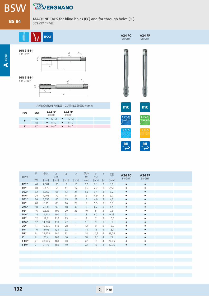
MDIN 13
ø d 2
L1
L2
L3
ø d 1
a
ø d 1
L1
L2
ø d 2 a
132 P.38
APPLICATION RANGE - CUTTING SPEED m/min
ISO MG A24 FCBRIGHT
A24 FPBRIGHT
PP.2 l 10-12 l 10-12
P.3 l 8-10 l 8-10
K K.2 l 8-10 l 8-10
A24 FPBRIGHT
A24 FCBRIGHT
MACHINE TAPS for blind holes (FC) and for through holes (FP)Straight flutes
P Ød1 L1 L2 L3 Ød2 a zA24 FCBRIGHT
A24 FPBRIGHT
BSW js 16 h9 h12
[TPI] [mm] [mm] [mm] [mm] [mm] [mm] [-] [mm]
3/32” 48 2,381 50 9 15 2,8 2,1 3 1,9 • •1/8” 40 3,175 56 11 17 3,5 2,7 3 2,55 • •5/32” 32 3,969 63 12 21 4,5 3,4 3 3,2 • •3/16” 24 4,763 70 14 24 6 4,9 3 3,7 • •7/32” 24 5,556 80 15 28 6 4,9 3 4,5 • •1/4” 20 6,35 80 16 29 7 5,5 3 5,1 • •5/16” 18 7,938 90 18 33 8 6,2 3 6,5 • •3/8” 16 9,525 100 20 36 10 8 3 7,9 • •7/16” 14 11,113 100 22 - 8 6,2 3 9,25 • •1/2” 12 12,7 110 25 - 9 7 3 10,5 • •9/16” 12 14,288 110 27 - 11 9 3 12 • •5/8” 11 15,875 110 28 - 12 9 3 13,5 • • 3/4” 10 19,05 125 32 - 14 11 4 16,4 • •7/8” 9 22,225 140 32 - 18 14,5 4 19,25 • •1” 8 25,4 160 36 - 18 14,5 4 22 • •1 1/8” 7 28,575 180 40 - 22 18 4 24,75 • •1 1/4” 7 31,75 180 40 - 22 18 4 27,75 • •
DIN 2184-1≤ Ø 3/8”
DIN 2184-1≥ Ø 7/16”
BSWBS 84
A SE
RIE
S

MDIN 13
133P.39
A31TiN
A31BRIGHT
P Ød1 L1 L2 L3 Ød2 a zA31
BRIGHTA31TiN
BSW js 16 h9 h12
[TPI] [mm] [mm] [mm] [mm] [mm] [mm] [-] [mm]
3/32” 48 2,381 50 9 15 2,8 2,1 3 1,9 • •1/8” 40 3,175 56 11 17 3,5 2,7 3 2,55 • •5/32” 32 3,969 63 12 21 4,5 3,4 3 3,2 • •3/16” 24 4,763 70 14 24 6 4,9 3 3,7 • •7/32” 24 5,556 80 15 28 6 4,9 3 4,5 • •1/4” 20 6,35 80 16 29 7 5,5 3 5,1 • •5/16” 18 7,938 90 18 33 8 6,2 3 6,5 • •3/8” 16 9,525 100 20 36 10 8 3 7,9 • •7/16” 14 11,113 100 22 - 8 6,2 3 9,25 • •1/2” 12 12,7 110 25 - 9 7 3 10,5 • •9/16” 12 14,288 110 27 - 11 9 3 12 • •5/8” 11 15,875 110 28 - 12 9 3 13,5 • • 3/4” 10 19,05 125 32 - 14 11 4 16,4 • •7/8” 9 22,225 140 32 - 18 14,5 4 19,25 • •1” 8 25,4 160 36 - 18 14,5 4 22 • •1 1/8” 7 28,575 180 40 - 22 18 4 24,75 •1 1/4” 7 31,75 180 40 - 22 18 4 27,75 •
APPLICATION RANGE - CUTTING SPEED m/min
ISO MG A31BRIGHT
A31TiN
P
P.1 l 18-20 l 30-35
P.2 l 15-18 l 25-30
P.3 l 12-15 l 20-25
P.4 l 10-12 l 15-20
P.5 l 5-10
K K.2 l 12-15 l 20-25
N
N.1 l 18-20
N.2-3 l 15-18 l 25-30
N.5 l 15-18
N.6 l 12-15 l 20-25
MACHINE TAPS for blind holes15° spiral flutes
ø d 2
L1
L2
L3
ø d 1
a
ø d 1
L1
L2
ø d 2 a
DIN 2184-1≤ Ø 3/8”
DIN 2184-1≥ Ø 7/16”
BSWBS 84
A SE
RIE
S

MDIN 13
134 P.39
ø d 1
L1
L2ø
d 2 a
APPLICATION RANGE - CUTTING SPEED m/min
ISO MG A6 BBRIGHT
P
P.2 l 10-15
P.3 l 10-12
P.4 l 8-10
K K.2 l 10-12
A6 BBRIGHT
MACHINE TAPS for conical blind holesStraight flutes
NORM VERGNANO
P Ød1 L1 L2 L3 Ød2 a zA6 BBRIGHT
NPT js 16 h9 h12
[TPI] [mm] [mm] [mm] [mm] [mm] [mm] [-] [mm]
1/16” 27 7,938 63 12 - 6 4,9 4 6,15 (a) •1/8” 27 10,287 63 12 - 7 5,5 4 8,5 (a) •1/4” 18 13,716 63 18 - 11 9 4 11 (a) •3/8” 18 17,145 70 18 - 12 9 4 14,5 (a) •1/2” 14 21,336 80 23 - 16 12 4 17,85 (a) •3/4” 14 26,67 100 24 - 20 16 5 23,2 (a) •1” 11,5 33,401 110 30 - 25 20 5 29 (a) •1 1/4” 11,5 42,164 125 32 - 32 24 5 37,8 (a) •1 1/2” 11,5 48,26 140 32 - 36 29 6 44 (a) •2” 11,5 60,325 160 34 - 45 35 6 56 (a) •
(a) = Cylindrical hole (see page 256)
NPTASME
B1.20.1
A SE
RIE
S
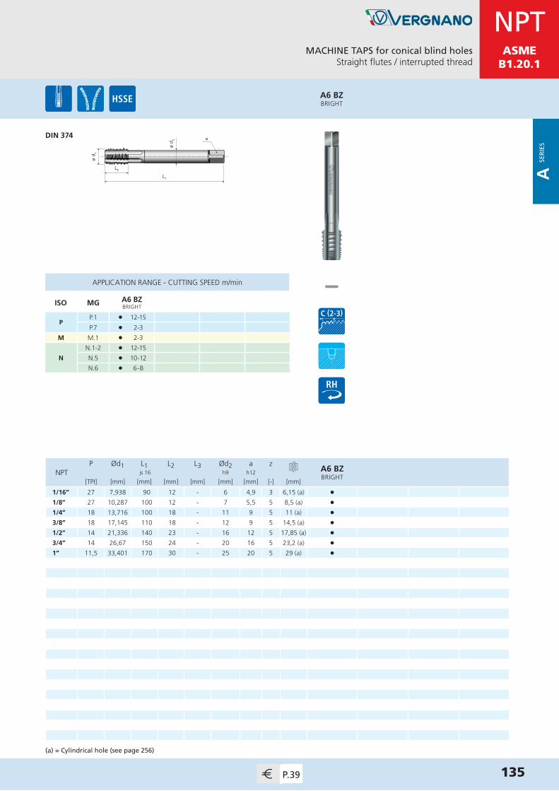
MDIN 13
MACHINE TAPS for conical blind holesStraight flutes / interrupted thread
135P.39
ø d 1
L1
L2ø
d 2 a
APPLICATION RANGE - CUTTING SPEED m/min
ISO MG A6 BZBRIGHT
PP.1 l 12-15
P.7 l 2-3
M M.1 l 2-3
N
N.1-2 l 12-15
N.5 l 10-12
N.6 l 6-8
A6 BZBRIGHT
DIN 374
P Ød1 L1 L2 L3 Ød2 a zA6 BZBRIGHT
NPT js 16 h9 h12
[TPI] [mm] [mm] [mm] [mm] [mm] [mm] [-] [mm]
1/16” 27 7,938 90 12 - 6 4,9 3 6,15 (a) •1/8” 27 10,287 100 12 - 7 5,5 5 8,5 (a) •1/4” 18 13,716 100 18 - 11 9 5 11 (a) •3/8” 18 17,145 110 18 - 12 9 5 14,5 (a) •1/2” 14 21,336 140 23 - 16 12 5 17,85 (a) •3/4” 14 26,67 150 24 - 20 16 5 23,2 (a) •1” 11,5 33,401 170 30 - 25 20 5 29 (a) •
(a) = Cylindrical hole (see page 256)
NPTASME
B1.20.1
A SE
RIE
S
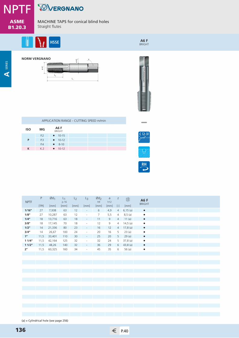
MDIN 13
136 P.40
ø d 1
L1
L2ø
d 2 a
APPLICATION RANGE - CUTTING SPEED m/min
ISO MG A6 FBRIGHT
P
P.2 l 10-15
P.3 l 10-12
P.4 l 8-10
K K.2 l 10-12
A6 FBRIGHT
MACHINE TAPS for conical blind holesStraight flutes
NORM VERGNANO
P Ød1 L1 L2 L3 Ød2 a zA6 F
BRIGHTNPTF js 16 h9 h12
[TPI] [mm] [mm] [mm] [mm] [mm] [mm] [-] [mm]
1/16” 27 7,938 63 12 - 6 4,9 4 6,15 (a) •1/8” 27 10,287 63 12 - 7 5,5 4 8,5 (a) •1/4” 18 13,716 63 18 - 11 9 4 11 (a) •3/8” 18 17,145 70 18 - 12 9 4 14,5 (a) •1/2” 14 21,336 80 23 - 16 12 4 17,8 (a) •3/4” 14 26,67 100 24 - 20 16 5 23 (a) •1” 11,5 33,401 110 30 - 25 20 5 29 (a) •1 1/4” 11,5 42,164 125 32 - 32 24 5 37,8 (a) •1 1/2” 11,5 48,26 140 32 - 36 29 6 43,8 (a) •2” 11,5 60,325 160 34 - 45 35 6 56 (a) •
(a) = Cylindrical hole (see page 256)
NPTFASME
B1.20.3
A SE
RIE
S

MDIN 13
MACHINE TAPS for conical blind holesStraight flutes / interrupted thread
137P.40
ø d 1
L1
L2ø
d 2 a
APPLICATION RANGE - CUTTING SPEED m/min
ISO MG A6 FZBRIGHT
PP.1 l 12-15
P.7 l 2-3
M M.1 l 2-3
N
N.1-2 l 12-15
N.5 l 10-12
N.6 l 6-8
A6 FZBRIGHT
DIN 374
P Ød1 L1 L2 L3 Ød2 a zA6 FZBRIGHT
NPTF js 16 h9 h12
[TPI] [mm] [mm] [mm] [mm] [mm] [mm] [-] [mm]
1/16” 27 7,938 90 12 - 6 4,9 3 6,15 (a) •1/8” 27 10,287 100 12 - 7 5,5 5 8,5 (a) •1/4” 18 13,716 100 18 - 11 9 5 11 (a) •3/8” 18 17,145 110 18 - 12 9 5 14,5 (a) •1/2” 14 21,336 140 23 - 16 12 5 17,8 (a) •3/4” 14 26,67 150 24 - 20 16 5 23 (a) •1” 11,5 33,401 170 30 - 25 20 5 29 (a) •
(a) = Cylindrical hole (see page 256)
NPTFASME
B1.20.3
A SE
RIE
S

PS E R I E S
High Performance Taps
P SER
IES

MDIN 13
ø d 2
L1
L2
L3
ø d 1
a
ø d 1
L1
L2
ø d 2 a
Ød1 P L1 L2 L3 Ød2 a zP43
V-MAXXBP43
V-MAXX js 16 h9 h12
[mm] [mm] [mm] [mm] [mm] [mm] [mm] [-] [mm]
M 3 0,5 56 10 18 3,5 2,7 3 2,5 •4 0,7 63 12 21 4,5 3,4 4 3,3 •5 0,8 70 14 24,5 6 4,9 4 4,2 • •6 1 80 16 29 6 4,9 4 5 • •8 1,25 90 18 33 8 6,2 4 6,8 • •10 1,5 100 20 36 10 8 4 8,5 • •12 1,75 110 24 - 9 7 4 10,2 • •14 2 110 25 - 11 9 4 12 • •16 2 110 28 - 12 9 4 14 • •18 2,5 125 32 - 14 11 4 15,5 • •20 2,5 140 32 - 16 12 4 17,5 • •
BP43V-MAXX
P43V-MAXX
HIGH PERFORMANCE MACHINE TAPS for blind and through holesStraight flutes / for cast iron
DIN 371≤ M10
DIN 376≥ M12
140 P.41
MDIN 13
APPLICATION RANGE - CUTTING SPEED m/min
ISO MG P43V-MAXX
BP43V-MAXX
K K.1 l 40-50 l 40-50
N
N.4 l 40-50 l 40-50
N.7 l 40-50 l 40-50
N.9-10 l 45-55 l 45-55
P SER
IES
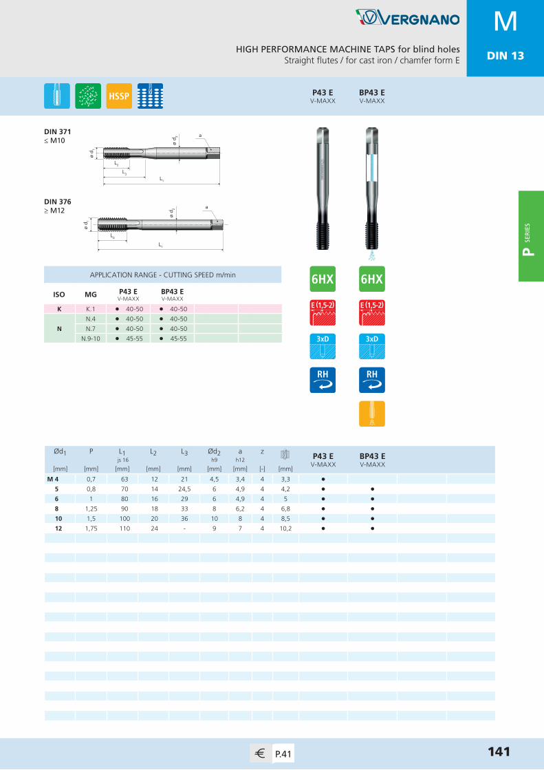
MDIN 13
HIGH PERFORMANCE MACHINE TAPS for blind holesStraight flutes / for cast iron / chamfer form E
141P.41
MDIN 13
ø d 2
L1
L2
L3
ø d 1
a
ø d 1
L1
L2
ø d 2 a
Ød1 P L1 L2 L3 Ød2 a zP43 E
V-MAXXBP43 EV-MAXX
js 16 h9 h12
[mm] [mm] [mm] [mm] [mm] [mm] [mm] [-] [mm]
M 4 0,7 63 12 21 4,5 3,4 4 3,3 •5 0,8 70 14 24,5 6 4,9 4 4,2 • •6 1 80 16 29 6 4,9 4 5 • •8 1,25 90 18 33 8 6,2 4 6,8 • •10 1,5 100 20 36 10 8 4 8,5 • •12 1,75 110 24 - 9 7 4 10,2 • •
BP43 EV-MAXX
P43 EV-MAXX
DIN 371≤ M10
DIN 376≥ M12
APPLICATION RANGE - CUTTING SPEED m/min
ISO MG P43 EV-MAXX
BP43 EV-MAXX
K K.1 l 40-50 l 40-50
N
N.4 l 40-50 l 40-50
N.7 l 40-50 l 40-50
N.9-10 l 45-55 l 45-55
P SER
IES
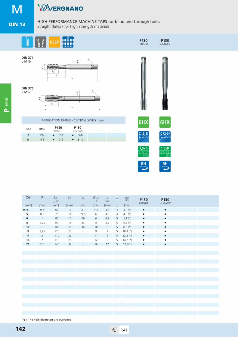
MDIN 13
ø d 2
L1
L2
L3
ø d 1
a
ø d 1
L1
L2
ø d 2 a
Ød1 P L1 L2 L3 Ød2 a zP130BRIGHT
P130V-MAXX
js 16 h9 h12
[mm] [mm] [mm] [mm] [mm] [mm] [mm] [-] [mm]
M 4 0,7 63 12 21 4,5 3,4 4 3,4 (*) • •5 0,8 70 14 24,5 6 4,9 4 4,3 (*) • •6 1 80 16 29 6 4,9 5 5,1 (*) • •8 1,25 90 18 33 8 6,2 5 6,9 (*) • •10 1,5 100 20 36 10 8 5 8,6 (*) • •12 1,75 110 24 - 9 7 5 10,4 (*) • •14 2 110 25 - 11 9 5 12,2 (*) • •16 2 110 28 - 12 9 5 14,2 (*) • •20 2,5 140 32 - 16 12 5 17,7(*) • •
P130V-MAXX
P130BRIGHT
HIGH PERFORMANCE MACHINE TAPS for blind and through holesStraight flutes / for high strength materials
142 P.41
MDIN 13
APPLICATION RANGE - CUTTING SPEED m/min
ISO MG P130BRIGHT
P130V-MAXX
P P.6 l 2-3 l 5-8
N N.8 l 3-5 l 8-10
DIN 371≤ M10
DIN 376≥ M12
(*) = The hole diameters are oversized
P SER
IES

MDIN 13
ø d 2
L1
L2
L3
ø d 1
a
ø d 1
L1
L2
ø d 2 a
Ød1 P L1 L2 L3 Ød2 a zP15TiN
P15TiH1
P15 6GXTiH1
BP15TiH1
js 16 h9 h12
[mm] [mm] [mm] [mm] [mm] [mm] [mm] [-] [mm]
M 1(*) 0,25 40 5,5 7,5 2,5 2,1 2 0,75 • •1,2(*) 0,25 40 5,5 7,5 2,5 2,1 2 0,95 • •1,4(*) 0,3 40 7 10 2,5 2,1 2 1,1 • •1,6 0,35 40 8 11 2,5 2,1 2 1,25 • •1,7 0,35 40 8 11 2,5 2,1 2 1,35 • •1,8 0,35 40 8 11 2,5 2,1 2 1,45 • •2 0,4 45 7 11 2,8 2,1 3 1,6 • •2,5 0,45 50 9 15 2,8 2,1 3 2,05 • •3 0,5 56 10 18 3,5 2,7 3 2,5 • •4 0,7 63 12 21 4,5 3,4 3 3,3 • • •5 0,8 70 14 24,5 6 4,9 3 4,2 • • • •6 1 80 16 29 6 4,9 3 5 • • • •8 1,25 90 18 33 8 6,2 3 6,8 • • • •10 1,5 100 20 36 10 8 3 8,5 • • • •12 1,75 110 24 - 9 7 4 10,2 • • • •14 2 110 25 - 11 9 4 12 • • • •16 2 110 28 - 12 9 4 14 • • • •18 2,5 125 32 - 14 11 4 15,5 • •20 2,5 140 32 - 16 12 4 17,5 • •24 3 160 36 - 18 14,5 4 21 • •27 3 160 36 - 20 16 4 24 • •30 3,5 180 40 - 22 18 4 26,5 • •33 3,5 180 40 - 25 20 5 29,5 • •36 4 200 55 - 28 22 5 32 • •
BP15TiH1
P15 6GXTiH1
P15TiH1
P15TiN
HIGH PERFORMANCE MACHINE TAPS for through holesStraight flutes with spiral point
143P.41
MDIN 13
APPLICATION RANGE - CUTTING SPEED m/min
ISO MG P15TiN
P15TiH1
P15 6GXTiH1
BP15TiH1
P
P.3 l 25-35 l 25-35 l 25-35 l 25-35
P.4 l 20-30 l 20-30 l 20-30 l 20-30
P.5 l 10-20 l 10-20 l 10-20 l 10-20
P.6 l 8-10 l 8-10 l 8-10 l 8-10
P.7 l 10-20 l 10-20 l 10-20 l 10-20
MM.1 l 10-20 l 10-20 l 10-20 l 10-20
M.2 l 6-8 l 6-8 l 6-8 l 6-8
K K.2 l 25-35 l 25-35 l 25-35 l 25-35
NN.2-3 l 30-40 l 30-40 l 30-40 l 30-40
N.6 l 25-35 l 25-35 l 25-35 l 25-35
DIN 371≤ M10
DIN 376≥ M12
(*) = Tolerance 5HX
P SER
IES

MDIN 13
ø d 2
L1
L2
L3
ø d 1
a
ø d 1
L1
L2
ø d 2 a
Ød1 P L1 L2 L3 Ød2 a zP29
BRIGHTP29TiN
P29TiH1
BP29TiH1
js 16 h9 h12
[mm] [mm] [mm] [mm] [mm] [mm] [mm] [-] [mm]
M 2 0,4 45 5 12 2,8 2,1 3 1,6 • • •2,5 0,45 50 6 15 2,8 2,1 3 2,05 • • • 3 0,5 56 5 18 3,5 2,7 3 2,5 • • •4 0,7 63 7 21 4,5 3,4 3 3,3 • • •5 0,8 70 9 25 6 4,9 3 4,2 • • • •6 1 80 11 30 6 4,9 3 5 • • • •8 1,25 90 12 35 8 6,2 3 6,8 • • • •10 1,5 100 13 39 10 8 3 8,5 • • • •12 1,75 110 15 - 9 7 3 10,2 • • • •14 2 110 18 - 11 9 3 12 • • • •16 2 110 18 - 12 9 3 14 • • • •18 2,5 125 20 - 14 11 4 15,5 • • • •20 2,5 140 20 - 16 12 4 17,5 • • • •24 3 160 25 - 18 14,5 4 21 • • •27 3 160 25 - 20 16 4 24 • • •30 3,5 180 29 - 22 18 4 26,5 • • •36 4 200 34 - 28 22 4 32 • • •
APPLICATION RANGE - CUTTING SPEED m/min
ISO MG P29BRIGHT
P29TiN
P29TiH1
BP29TiH1
P
P.3 l 15-18 l 25-30 l 25-30 l 25-30
P.4 l 12-15 l 20-25 l 20-25 l 20-25
P.5 l 8-10 l 10-15 l 10-15 l 10-15
P.6 l 3-5 l 5-10 l 5-10 l 5-10
P.7 l 8-10 l 10-15 l 10-15 l 10-15
K K.2 l 15-18 l 25-30 l 25-30 l 25-30
N
N.3 l 15-18 l 25-30 l 25-30 l 25-30
N.6 l 15-18 l 25-30 l 25-30 l 25-30
N.7 l 12-15 l 20-25 l 20-25 l 20-25
SS.2 l 2-3 l 2-3 l 2-3
S.4 l 2-3 l 2-3 l 2-3 l 2-3
HIGH PERFORMANCE MACHINE TAPS for blind holes15° spiral flutes
DIN 371≤ M10
DIN 376≥ M12
144 P.42
MDIN 13
BP29TiH1
P29TiH1
P29TiN
P29BRIGHT
P SER
IES

MDIN 13
Ød1 P L1 L2 L3 Ød2 a zP29 E
TiH1 js 16 h9 h12
[mm] [mm] [mm] [mm] [mm] [mm] [mm] [-] [mm]
M 3 0,5 56 5 18 3,5 2,7 3 2,5 •4 0,7 63 7 21 4,5 3,4 3 3,3 • 5 0,8 70 9 25 6 4,9 3 4,2 •6 1 80 11 30 6 4,9 3 5 •8 1,25 90 12 35 8 6,2 3 6,8 •10 1,5 100 13 39 10 8 3 8,5 •12 1,75 110 15 - 9 7 3 10,2 •
P29 ETiH1
HIGH PERFORMANCE MACHINE TAPS for blind holes15° spiral flutes / chamfer form E
145P.42
MDIN 13
ø d 2
L1
L2
L3
ø d 1
a
ø d 1
L1
L2
ø d 2 a
DIN 371≤ M10
DIN 376≥ M12
APPLICATION RANGE - CUTTING SPEED m/min
ISO MG P29 ETiH1
P
P.3 l 25-30
P.4 l 20-25
P.5 l 10-15
P.6 l 5-10
P.7 l 10-15
K K.2 l 25-30
N
N.3 l 25-30
N.6 l 25-30
N.7 l 20-25
SS.2 l 2-3
S.4 l 2-3
P SER
IES
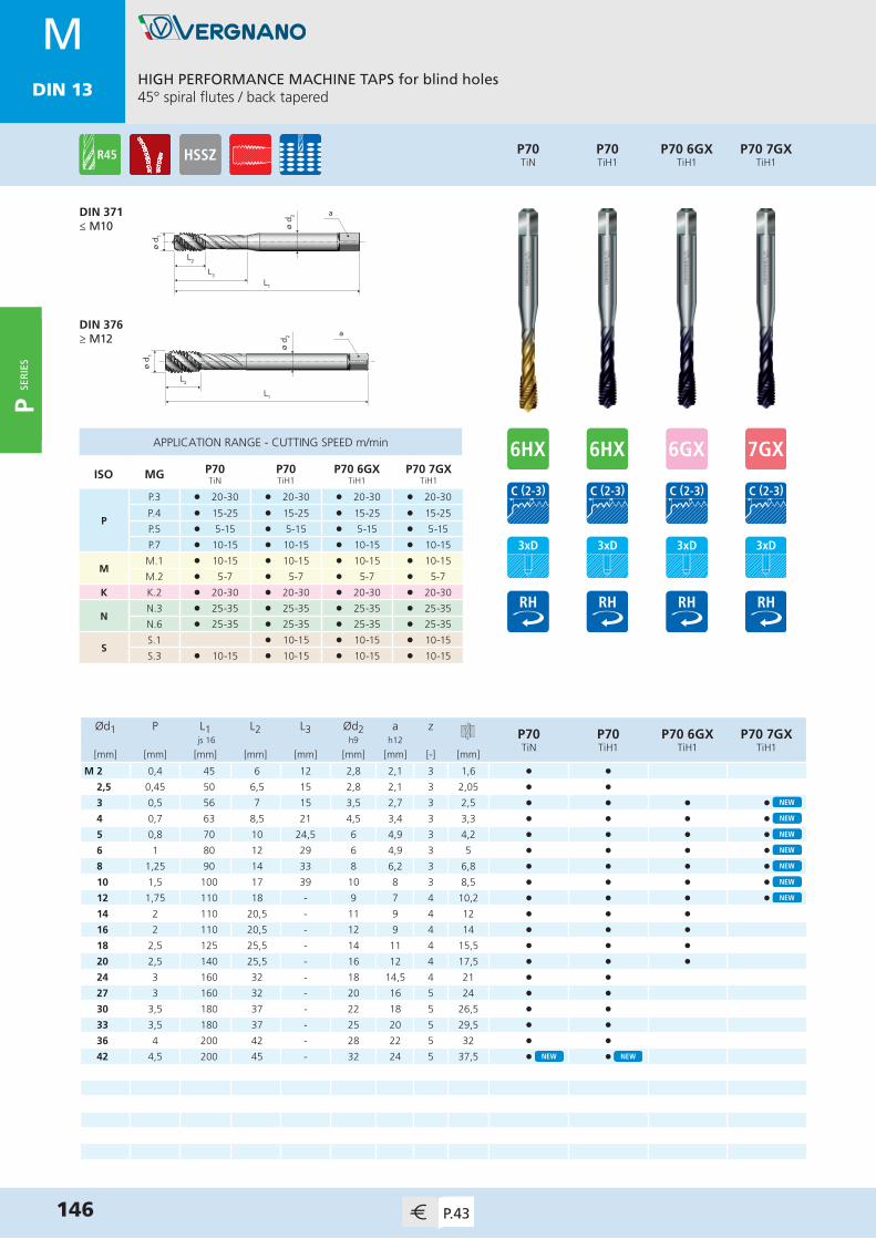
MDIN 13
HIGH PERFORMANCE MACHINE TAPS for blind holes45° spiral flutes / back tapered
146 P.43
MDIN 13
ø d 2
L1
L2
L3
ø d 1
a
ø d 1
L1
L2
ø d 2 a
Ød1 P L1 L2 L3 Ød2 a zP70TiN
P70TiH1
P70 6GXTiH1
P70 7GXTiH1
js 16 h9 h12
[mm] [mm] [mm] [mm] [mm] [mm] [mm] [-] [mm]
M 2 0,4 45 6 12 2,8 2,1 3 1,6 • •2,5 0,45 50 6,5 15 2,8 2,1 3 2,05 • •3 0,5 56 7 15 3,5 2,7 3 2,5 • • • • 4 0,7 63 8,5 21 4,5 3,4 3 3,3 • • • • 5 0,8 70 10 24,5 6 4,9 3 4,2 • • • • 6 1 80 12 29 6 4,9 3 5 • • • • 8 1,25 90 14 33 8 6,2 3 6,8 • • • • 10 1,5 100 17 39 10 8 3 8,5 • • • • 12 1,75 110 18 - 9 7 4 10,2 • • • • 14 2 110 20,5 - 11 9 4 12 • • •16 2 110 20,5 - 12 9 4 14 • • •18 2,5 125 25,5 - 14 11 4 15,5 • • •20 2,5 140 25,5 - 16 12 4 17,5 • • •24 3 160 32 - 18 14,5 4 21 • •27 3 160 32 - 20 16 5 24 • •30 3,5 180 37 - 22 18 5 26,5 • •33 3,5 180 37 - 25 20 5 29,5 • •36 4 200 42 - 28 22 5 32 • •42 4,5 200 45 - 32 24 5 37,5 • •
APPLICATION RANGE - CUTTING SPEED m/min
ISO MG P70TiN
P70TiH1
P70 6GXTiH1
P70 7GXTiH1
P
P.3 l 20-30 l 20-30 l 20-30 l 20-30
P.4 l 15-25 l 15-25 l 15-25 l 15-25
P.5 l 5-15 l 5-15 l 5-15 l 5-15
P.7 l 10-15 l 10-15 l 10-15 l 10-15
MM.1 l 10-15 l 10-15 l 10-15 l 10-15
M.2 l 5-7 l 5-7 l 5-7 l 5-7
K K.2 l 20-30 l 20-30 l 20-30 l 20-30
NN.3 l 25-35 l 25-35 l 25-35 l 25-35
N.6 l 25-35 l 25-35 l 25-35 l 25-35
SS.1 l 10-15 l 10-15 l 10-15
S.3 l 10-15 l 10-15 l 10-15 l 10-15
DIN 371≤ M10
DIN 376≥ M12
P70 7GXTiH1
P70 6GXTiH1
P70TiH1
P70TiN
P SER
IES

MDIN 13
Ød1 P L1 L2 L3 Ød2 a zBP70TiH1
js 16 h9 h12
[mm] [mm] [mm] [mm] [mm] [mm] [mm] [-] [mm]
M 5 0,8 70 10 24,5 6 4,9 3 4,2 •6 1 80 12 29 6 4,9 3 5 •8 1,25 90 14 33 8 6,2 3 6,8 •10 1,5 100 17 39 10 8 3 8,5 •12 1,75 110 18 - 9 7 4 10,2 •14 2 110 20,5 - 11 9 4 12 •16 2 110 20,5 - 12 9 4 14 •
BP70TiH1
HIGH PERFORMANCE MACHINE TAPS for blind holes45° spiral flutes / back tapered / internal coolant
147P.43
MDIN 13
APPLICATION RANGE - CUTTING SPEED m/min
ISO MG BP70TiH1
P
P.3 l 20-30
P.4 l 15-25
P.5 l 5-15
P.7 l 10-15
MM.1 l 10-15
M.2 l 5-7
K K.2 l 20-30
NN.3 l 25-35
N.6 l 25-35
SS.1 l 10-15
S.3 l 10-15
ø d 2
L1
L2
L3
ø d 1
a
ø d 1
L1
L2
ø d 2 a
DIN 371≤ M10
DIN 376≥ M12
P SER
IES

MDIN 13
HIGH PERFORMANCE MACHINE TAPS for blind holes45° spiral flutes / back tapered / chamfer form E
148 P.43
MDIN 13
ø d 2
L1
L2
L3
ø d 1
a
ø d 1
L1
L2
ø d 2 a
Ød1 P L1 L2 L3 Ød2 a zP70 E
TiNP70 E
TiH1P70 E 6GX
TiH1 js 16 h9 h12
[mm] [mm] [mm] [mm] [mm] [mm] [mm] [-] [mm]
M 2 0,4 45 6 12 2,8 2,1 3 1,6 • • 2,5 0,45 50 6,5 15 2,8 2,1 3 2,05 • • 3 0,5 56 7 15 3,5 2,7 3 2,5 • • •4 0,7 63 8,5 21 4,5 3,4 3 3,3 • • •5 0,8 70 10 24,5 6 4,9 3 4,2 • • •6 1 80 12 29 6 4,9 3 5 • • •8 1,25 90 14 33 8 6,2 4 6,8 • • •10 1,5 100 17 39 10 8 4 8,5 • • •12 1,75 110 18 - 9 7 4 10,2 • • •14 2 110 20,5 - 11 9 5 12 • • •16 2 110 20,5 - 12 9 5 14 • • •20 2,5 140 25,5 - 16 12 5 17,5 • •
APPLICATION RANGE - CUTTING SPEED m/min
ISO MG P70 ETiN
P70 ETiH1
P70 E 6GXTiH1
P
P.3 l 20-30 l 20-30 l 20-30
P.4 l 15-25 l 15-25 l 15-25
P.5 l 5-15 l 5-15 l 5-15
P.7 l 10-15 l 10-15 l 10-15
MM.1 l 10-15 l 10-15 l 10-15
M.2 l 5-7 l 5-7 l 5-7
K K.2 l 20-30 l 20-30 l 20-30
NN.3 l 25-35 l 25-35 l 25-35
N.6 l 25-35 l 25-35 l 25-35
SS.1 l 10-15 l 10-15
S.3 l 10-15 l 10-15 l 10-15
DIN 371≤ M10
DIN 376≥ M12
P70 ETiN
P70 ETiH1
P70 E 6GXTiH1
P SER
IES
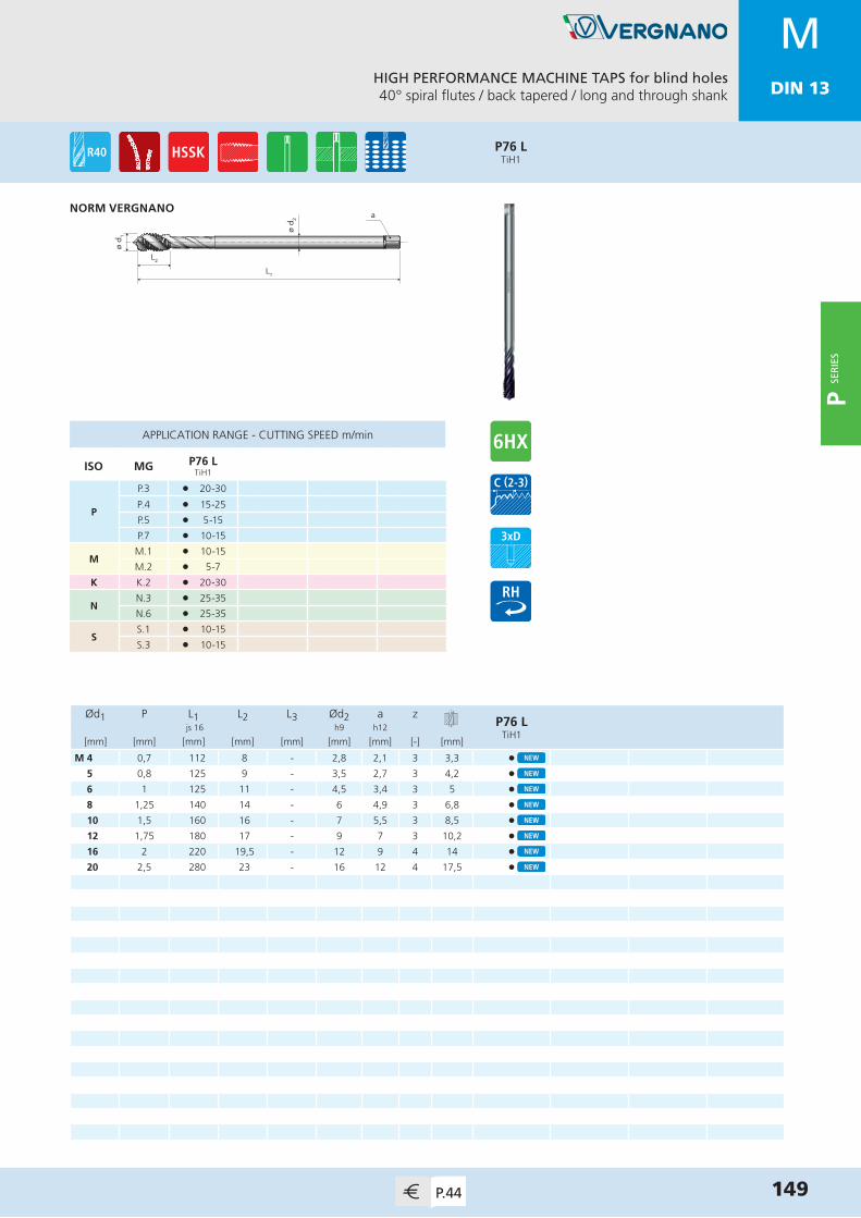
MDIN 13
Ød1 P L1 L2 L3 Ød2 a zP76 L
TiH1 js 16 h9 h12
[mm] [mm] [mm] [mm] [mm] [mm] [mm] [-] [mm]
M 4 0,7 112 8 - 2,8 2,1 3 3,3 •5 0,8 125 9 - 3,5 2,7 3 4,2 •6 1 125 11 - 4,5 3,4 3 5 •8 1,25 140 14 - 6 4,9 3 6,8 •10 1,5 160 16 - 7 5,5 3 8,5 •12 1,75 180 17 - 9 7 3 10,2 •16 2 220 19,5 - 12 9 4 14 •20 2,5 280 23 - 16 12 4 17,5 •
P76 LTiH1
HIGH PERFORMANCE MACHINE TAPS for blind holes40° spiral flutes / back tapered / long and through shank
149P.44
MDIN 13
APPLICATION RANGE - CUTTING SPEED m/min
ISO MG P76 LTiH1
P
P.3 l 20-30
P.4 l 15-25
P.5 l 5-15
P.7 l 10-15
MM.1 l 10-15
M.2 l 5-7
K K.2 l 20-30
NN.3 l 25-35
N.6 l 25-35
SS.1 l 10-15
S.3 l 10-15
ø d 2
L1
L2
ø d 1
aNORM VERGNANO
P SER
IES

MDIN 13
HIGH PERFORMANCE COLD FORMING TAPS for blind and through holesWithout oil grooves
150 P.44
MDIN 13
ø d 2
L1
L2
L3
ø d 1
a
ø d 1
L1
L2
ø d 2 a
Ød1 P L1 L2 L3 Ød2 a zP80TiN
P80V-MAXX
P80 6GXTiN
P80 7GXTiN
js 16 h9 h12
[mm] [mm] [mm] [mm] [mm] [mm] [mm] [-] [mm]
M 2 0,4 45 7 11 2,8 2,1 3 1,85 • • •2,5 0,45 50 9 15 2,8 2,1 3 2,3 • • •3 0,5 56 10 18 3,5 2,7 4 2,8 • • • •3,5 0,6 56 11 20 4 3 4 3,25 • • • •4 0,7 63 12 21 4,5 3,4 5 3,7 • • • •5 0,8 70 14 24,5 6 4,9 5 4,65 • • • •6 1 80 16 29 6 4,9 5 5,55 • • • •8 1,25 90 18 33 8 6,2 5 7,4 • • • •10 1,5 100 20 36 10 8 5 9,3 • • • •12 1,75 110 24 - 9 7 5 11,2 • • • •14 2 110 25 - 11 9 6 13,1 • • • •16 2 110 28 - 12 9 6 15,1 • • • •
P80 7GXTiN
P80 6GXTiN
P80V-MAXX
P80TiN
APPLICATION RANGE - CUTTING SPEED m/min
ISO MG P80TiN
P80V-MAXX
P80 6GXTiN
P80 7GXTiN
P
P.1-2 l 40-45 l 40-45 l 40-45 l 40-45
P.3 l 35-40 l 35-40 l 35-40 l 35-40
P.4 l 30-35 l 30-35 l 30-35 l 30-35
P.5 l 15-20 l 15-20 l 15-20 l 15-20
P.7 l 15-20 l 15-20 l 15-20 l 15-20
M M.1 l 15-20 l 15-20 l 15-20 l 15-20
N
N.1-2 l 40-45 l 40-45 l 40-45 l 40-45
N.3 l 35-40 l 35-40 l 35-40 l 35-40
N.5-6 l 40-45 l 40-45 l 40-45 l 40-45
S S.3 l 10-15 l 10-15 l 10-15 l 10-15
DIN 2174 (371)≤ M10
DIN 2174 (376)≥ M12
P SER
IES

MDIN 13
HIGH PERFORMANCE COLD FORMING TAPS for blind and through holesWith oil grooves
151P.44
MDIN 13
ø d 2
L1
L2
L3
ø d 1
a
ø d 1
L1
L2
ø d 2 a
Ød1 P L1 L2 L3 Ød2 a zP80 N
TiNP80 NV-MAXX
P80 N 6GXTiN
P80 N 7GXTiN
js 16 h9 h12
[mm] [mm] [mm] [mm] [mm] [mm] [mm] [-] [mm]
M 2 0,4 45 7 11 2,8 2,1 3 1,85 • • •2,5 0,45 50 9 15 2,8 2,1 3 2,3 • • •3 0,5 56 10 18 3,5 2,7 4 2,8 • • • •3,5 0,6 56 11 20 4 3 4 3,25 • • • •4 0,7 63 12 21 4,5 3,4 5 3,7 • • • •5 0,8 70 14 24,5 6 4,9 5 4,65 • • • •6 1 80 16 29 6 4,9 5 5,55 • • • •8 1,25 90 18 33 8 6,2 5 7,4 • • • •10 1,5 100 20 36 10 8 5 9,3 • • • •12 1,75 110 24 - 9 7 5 11,2 • • • •14 2 110 25 - 11 9 6 13,1 • • • •16 2 110 28 - 12 9 6 15,1 • • • •18 2,5 125 28 - 14 11 8 16,9 • • •20 2,5 140 30 - 16 12 8 18,9 • • •
P80 N 7GXTiN
P80 N 6GXTiN
P80 NV-MAXX
P80 NTiN
APPLICATION RANGE - CUTTING SPEED m/min
ISO MG P80 NTiN
P80 NV-MAXX
P80 N 6GXTiN
P80 N 7GXTiN
P
P.1-2 l 40-45 l 40-45 l 40-45 l 40-45
P.3 l 35-40 l 35-40 l 35-40 l 35-40
P.4 l 30-35 l 30-35 l 30-35 l 30-35
P.5 l 15-20 l 15-20 l 15-20 l 15-20
P.7 l 15-20 l 15-20 l 15-20 l 15-20
M M.1 l 15-20 l 15-20 l 15-20 l 15-20
N
N.1-2 l 40-45 l 40-45 l 40-45 l 40-45
N.3 l 35-40 l 35-40 l 35-40 l 35-40
N.5-6 l 40-45 l 40-45 l 40-45 l 40-45
S S.3 l 10-15 l 10-15 l 10-15 l 10-15
DIN 2174 (371)≤ M10
DIN 2174 (376)≥ M12
P SER
IES

MDIN 13
HIGH PERFORMANCE COLD FORMING TAPS for blind holesChamfer form E
152 P.45
MDIN 13
ø d 2
L1
L2
L3
ø d 1
a
ø d 1
L1
L2
ø d 2 a
Ød1 P L1 L2 L3 Ød2 a zP80 E
TiNP80 N E
TiNP80 N EV-MAXX
P80 N E 6GXTiN
js 16 h9 h12
[mm] [mm] [mm] [mm] [mm] [mm] [mm] [-] [mm]
M 3 0,5 56 10 18 3,5 2,7 4 2,8 • • • •3,5 0,6 56 11 20 4 3 4 3,25 • • • •4 0,7 63 12 21 4,5 3,4 5 3,7 • • • •5 0,8 70 14 24,5 6 4,9 5 4,65 • • • •6 1 80 16 29 6 4,9 5 5,55 • • • •8 1,25 90 18 33 8 6,2 5 7,4 • • • •10 1,5 100 20 36 10 8 5 9,3 • • • •12 1,75 110 24 - 9 7 5 11,2 • •16 2 110 28 - 12 9 6 15,1 • •
P80 N E 6GXTiN
P80 N EV-MAXX
P80 N ETiN
P80 ETiN
APPLICATION RANGE - CUTTING SPEED m/min
ISO MG P80 ETiN
P80 N ETiN
P80 N EV-MAXX
P80 N E 6GXTiN
P
P.1-2 l 40-45 l 40-45 l 40-45 l 40-45
P.3 l 35-40 l 35-40 l 35-40 l 35-40
P.4 l 30-35 l 30-35 l 30-35 l 30-35
P.5 l 15-20 l 15-20 l 15-20 l 15-20
P.7 l 15-20 l 15-20 l 15-20 l 15-20
M M.1 l 15-20 l 15-20 l 15-20 l 15-20
N
N.1-2 l 40-45 l 40-45 l 40-45 l 40-45
N.3 l 35-40 l 35-40 l 35-40 l 35-40
N.5-6 l 40-45 l 40-45 l 40-45 l 40-45
S S.3 l 10-15 l 10-15 l 10-15 l 10-15
DIN 2174 (371)≤ M10
DIN 2174 (376)≥ M12
P SER
IES

MDIN 13
HIGH PERFORMANCE COLD FORMING TAPS for blind and through holesWith oil grooves / internal coolant
153P.45
MDIN 13
ø d 2
L1
L2
L3
ø d 1
a
ø d 1
L1
L2
ø d 2 a
Ød1 P L1 L2 L3 Ød2 a zBP80 N
TiNBP80 N R
TiNBP80 N R
V-MAXXBP80 N E
V-MAXX js 16 h9 h12
[mm] [mm] [mm] [mm] [mm] [mm] [mm] [-] [mm]
M 5 0,8 70 14 24,5 6 4,9 5 4,65 • • • •6 1 80 16 29 6 4,9 5 5,55 • • • •8 1,25 90 18 33 8 6,2 5 7,4 • • • •10 1,5 100 20 36 10 8 5 9,3 • • • •12 1,75 110 24 - 9 7 5 11,2 • • • •16 2 110 28 - 12 9 6 15,1 • • • •20 2,5 140 30 - 16 12 8 18,9 • •24 3 160 35 - 18 14,5 8 22,7 •27 3 160 35 - 20 16 8 25,7 •30 3,5 180 40 - 22 18 8 28,45 •
BP80 N E V-MAXX
BP80 N RV-MAXX
BP80 N RTiN
BP80 NTiN
APPLICATION RANGE - CUTTING SPEED m/min
ISO MG BP80 NTiN
BP80 N RTiN
BP80 N RV-MAXX
BP80 N E V-MAXX
P
P.1-2 l 40-45 l 40-45 l 40-45 l 40-45
P.3 l 35-40 l 35-40 l 35-40 l 35-40
P.4 l 30-35 l 30-35 l 30-35 l 30-35
P.5 l 15-20 l 15-20 l 15-20 l 15-20
P.7 l 15-20 l 15-20 l 15-20 l 15-20
M M.1 l 15-20 l 15-20 l 15-20 l 15-20
N
N.1-2 l 40-45 l 40-45 l 40-45 l 40-45
N.3 l 35-40 l 35-40 l 35-40 l 35-40
N.5-6 l 40-45 l 40-45 l 40-45 l 40-45
S S.3 l 10-15 l 10-15 l 10-15 l 10-15
DIN 2174 (371)≤ M10
DIN 2174 (376)≥ M12
P SER
IES

MDIN 13
HIGH PERFORMANCE COLD FORMING TAPS for blind and through holesWith oil grooves
154 P.45
MDIN 13
ø d 2
L1
L2
L3
ø d 1
a
ø d 1
L1
L2
L3
ø d 2 a
Ød1 P L1 L2 L3 Ød2 a zP80 N LH
TiN js 16 h9 h12
[mm] [mm] [mm] [mm] [mm] [mm] [mm] [-] [mm]
M 3 0,5 56 10 18 3,5 2,7 4 2,8 •4 0,7 63 12 21 4,5 3,4 5 3,7 •5 0,8 70 14 24,5 6 4,9 5 4,65 •6 1 80 16 29 6 4,9 5 5,55 •8 1,25 90 18 33 8 6,2 5 7,4 •10 1,5 100 20 36 10 8 5 9,3 •12 1,75 110 24 - 9 7 5 11,2 •
P80 N LHTiN
APPLICATION RANGE - CUTTING SPEED m/min
ISO MG P80 N LHTiN
P
P.1-2 l 40-45
P.3 l 35-40
P.4 l 30-35
P.5 l 15-20
P.7 l 15-20
M M.1 l 15-20
N
N.1-2 l 40-45
N.3 l 35-40
N.5-6 l 40-45
S S.3 l 10-15
DIN 2174 (371)≤ M10
DIN 2174 (376)≥ M12
P SER
IES
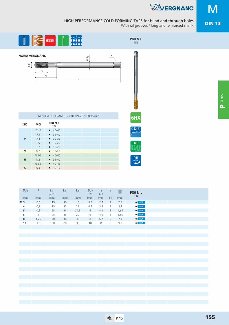
MDIN 13
Ød1 P L1 L2 L3 Ød2 a zP80 N L
TiN js 16 h9 h12
[mm] [mm] [mm] [mm] [mm] [mm] [mm] [-] [mm]
M 3 0,5 115 10 18 3,5 2,7 4 2,8 •4 0,7 115 12 21 4,5 3,4 5 3,7 •5 0,8 125 14 24,5 6 4,9 5 4,65 •6 1 125 16 29 6 4,9 5 5,55 •8 1,25 140 18 33 8 6,2 5 7,4 •10 1,5 160 20 36 10 8 5 9,3 •
P80 N LTiN
HIGH PERFORMANCE COLD FORMING TAPS for blind and through holesWith oil grooves / long and reinforced shank
155P.45
APPLICATION RANGE - CUTTING SPEED m/min
ISO MG P80 N LTiN
P
P.1-2 l 40-45
P.3 l 35-40
P.4 l 30-35
P.5 l 15-20
P.7 l 15-20
M M.1 l 15-20
N
N.1-2 l 40-45
N.3 l 35-40
N.5-6 l 40-45
S S.3 l 10-15
MDIN 13
L1
L2
L3
ø d 1
a
ø d 2NORM VERGNANO
P SER
IES
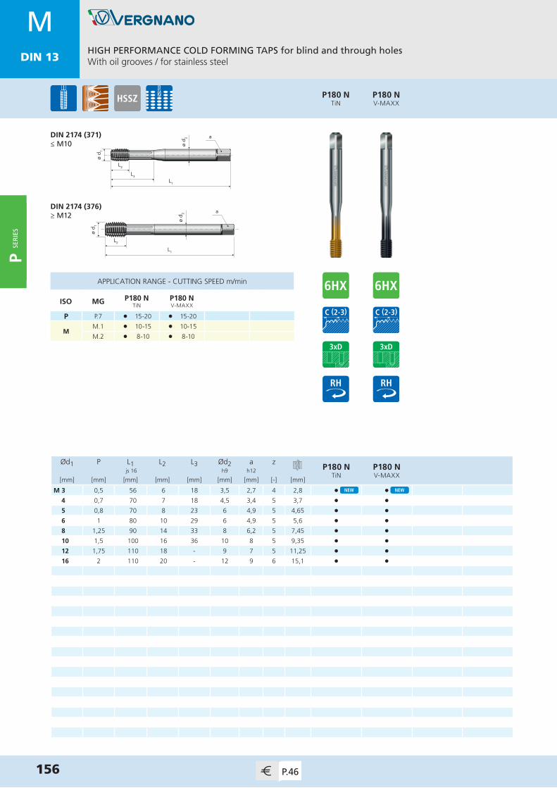
MDIN 13
Ød1 P L1 L2 L3 Ød2 a zP180 N
TiNP180 NV-MAXX
js 16 h9 h12
[mm] [mm] [mm] [mm] [mm] [mm] [mm] [-] [mm]
M 3 0,5 56 6 18 3,5 2,7 4 2,8 • •4 0,7 70 7 18 4,5 3,4 5 3,7 • •5 0,8 70 8 23 6 4,9 5 4,65 • •6 1 80 10 29 6 4,9 5 5,6 • •8 1,25 90 14 33 8 6,2 5 7,45 • •10 1,5 100 16 36 10 8 5 9,35 • •12 1,75 110 18 - 9 7 5 11,25 • •16 2 110 20 - 12 9 6 15,1 • •
P180 NV-MAXX
P180 NTiN
HIGH PERFORMANCE COLD FORMING TAPS for blind and through holesWith oil grooves / for stainless steel
156 P.46
APPLICATION RANGE - CUTTING SPEED m/min
ISO MG P180 NTiN
P180 NV-MAXX
P P.7 l 15-20 l 15-20
MM.1 l 10-15 l 10-15
M.2 l 8-10 l 8-10
MDIN 13
ø d 2
L1
L2
L3
ø d 1
a
ø d 1
L1
L2
ø d 2 a
DIN 2174 (371)≤ M10
DIN 2174 (376)≥ M12
P SER
IES
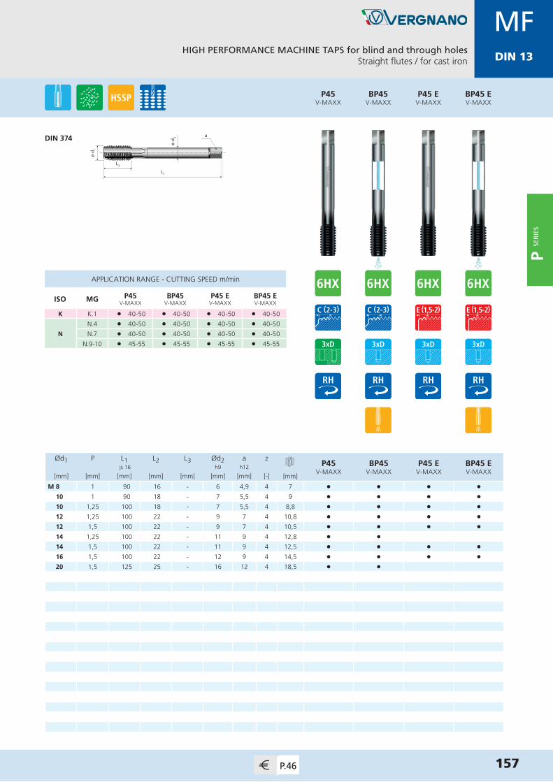
MDIN 13
ø d 1
L1
L2
ø d 2 a
Ød1 P L1 L2 L3 Ød2 a zP45
V-MAXXBP45
V-MAXXP45 E
V-MAXXBP45 EV-MAXX
js 16 h9 h12
[mm] [mm] [mm] [mm] [mm] [mm] [mm] [-] [mm]
M 8 1 90 16 - 6 4,9 4 7 • • • •10 1 90 18 - 7 5,5 4 9 • • • •10 1,25 100 18 - 7 5,5 4 8,8 • • • •12 1,25 100 22 - 9 7 4 10,8 • • • •12 1,5 100 22 - 9 7 4 10,5 • • • •14 1,25 100 22 - 11 9 4 12,8 • •14 1,5 100 22 - 11 9 4 12,5 • • • •16 1,5 100 22 - 12 9 4 14,5 • • • •20 1,5 125 25 - 16 12 4 18,5 • •
BP45V-MAXX
P45V-MAXX
HIGH PERFORMANCE MACHINE TAPS for blind and through holesStraight flutes / for cast iron
DIN 374
157P.46
APPLICATION RANGE - CUTTING SPEED m/min
ISO MG P45V-MAXX
BP45V-MAXX
P45 EV-MAXX
BP45 EV-MAXX
K K.1 l 40-50 l 40-50 l 40-50 l 40-50
N
N.4 l 40-50 l 40-50 l 40-50 l 40-50
N.7 l 40-50 l 40-50 l 40-50 l 40-50
N.9-10 l 45-55 l 45-55 l 45-55 l 45-55
MFDIN 13
P45 EV-MAXX
BP45 EV-MAXX
P SER
IES
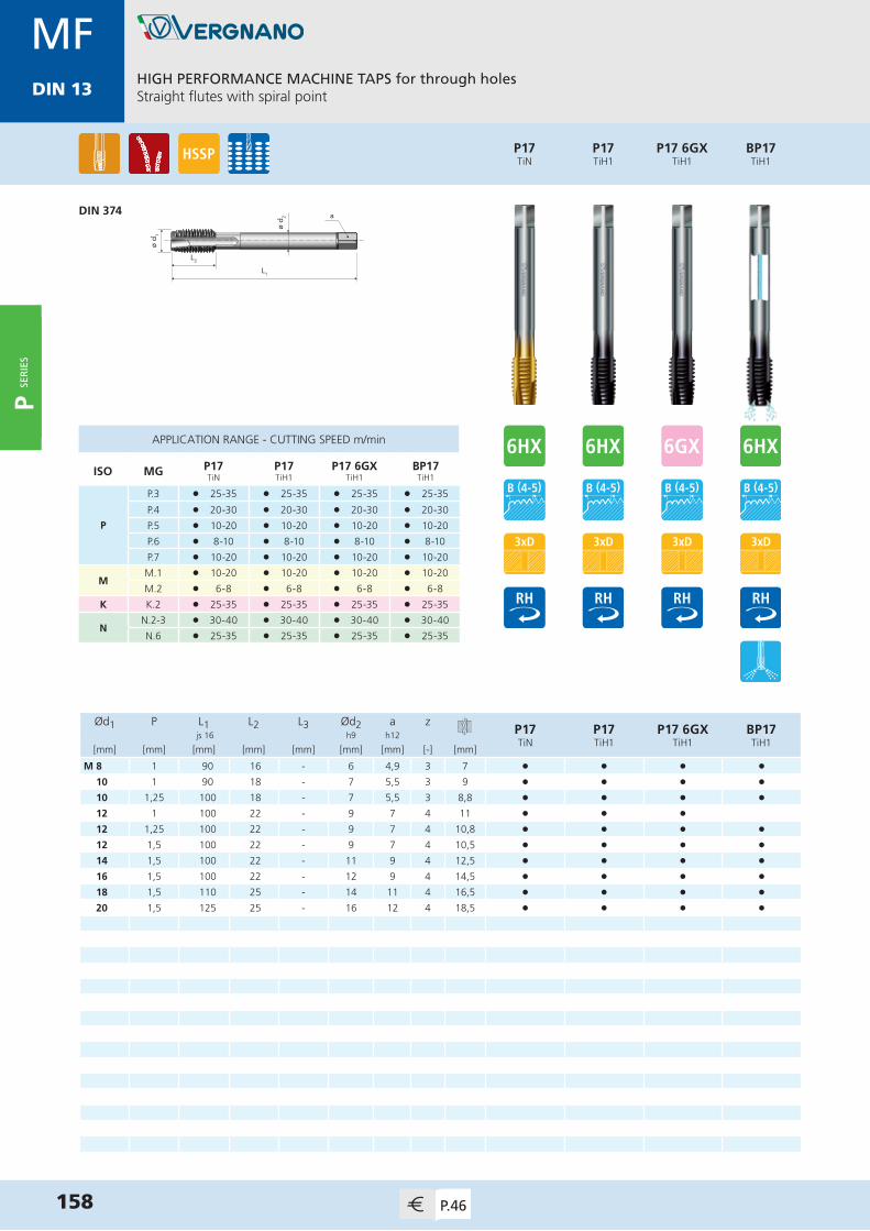
MDIN 13
ø d 1
L1
L2
ø d 2 a
Ød1 P L1 L2 L3 Ød2 a zP17TiN
P17TiH1
P17 6GXTiH1
BP17TiH1
js 16 h9 h12
[mm] [mm] [mm] [mm] [mm] [mm] [mm] [-] [mm]
M 8 1 90 16 - 6 4,9 3 7 • • • •10 1 90 18 - 7 5,5 3 9 • • • •10 1,25 100 18 - 7 5,5 3 8,8 • • • •12 1 100 22 - 9 7 4 11 • • •12 1,25 100 22 - 9 7 4 10,8 • • • •12 1,5 100 22 - 9 7 4 10,5 • • • •14 1,5 100 22 - 11 9 4 12,5 • • • •16 1,5 100 22 - 12 9 4 14,5 • • • •18 1,5 110 25 - 14 11 4 16,5 • • • •20 1,5 125 25 - 16 12 4 18,5 • • • •
APPLICATION RANGE - CUTTING SPEED m/min
ISO MG P17TiN
P17TiH1
P17 6GXTiH1
BP17TiH1
P
P.3 l 25-35 l 25-35 l 25-35 l 25-35
P.4 l 20-30 l 20-30 l 20-30 l 20-30
P.5 l 10-20 l 10-20 l 10-20 l 10-20
P.6 l 8-10 l 8-10 l 8-10 l 8-10
P.7 l 10-20 l 10-20 l 10-20 l 10-20
MM.1 l 10-20 l 10-20 l 10-20 l 10-20
M.2 l 6-8 l 6-8 l 6-8 l 6-8
K K.2 l 25-35 l 25-35 l 25-35 l 25-35
NN.2-3 l 30-40 l 30-40 l 30-40 l 30-40
N.6 l 25-35 l 25-35 l 25-35 l 25-35
HIGH PERFORMANCE MACHINE TAPS for through holesStraight flutes with spiral point
DIN 374
158 P.46
MFDIN 13
P17TiH1
P17TiN
P17 6GXTiH1
BP17TiH1
P SER
IES

MDIN 13
HIGH PERFORMANCE MACHINE TAPS for blind holes15° spiral flutes
159P.46
MFDIN 13
ø d 1
L1
L2
ø d 2 a
Ød1 P L1 L2 L3 Ød2 a zP30
BRIGHTP30TiN
P30TiH1
BP30TiH1
js 16 h9 h12
[mm] [mm] [mm] [mm] [mm] [mm] [mm] [-] [mm]
M 8 1 90 10 - 6 4,9 3 7 • • •10 1 90 11 - 7 5,5 3 9 • • •10 1,25 100 12 - 7 5,5 3 8,8 • • • •12 1,25 100 14 - 9 7 3 10,8 • • • •12 1,5 100 15 - 9 7 3 10,5 • • • •14 1,5 100 16 - 11 9 3 12,5 • • • •16 1,5 100 16 - 12 9 3 14,5 • • • •18 1,5 110 18 - 14 11 4 16,5 • • • •20 1,5 125 18 - 16 12 4 18,5 • • • •
APPLICATION RANGE - CUTTING SPEED m/min
ISO MG P30BRIGHT
P30TiN
P30TiH1
BP30TiH1
P
P.3 l 15-18 l 25-30 l 25-30 l 25-30
P.4 l 12-15 l 20-25 l 20-25 l 20-25
P.5 l 8-10 l 10-15 l 10-15 l 10-15
P.6 l 3-5 l 5-10 l 5-10 l 5-10
P.7 l 8-10 l 10-15 l 10-15 l 10-15
K K.2 l 15-18 l 25-30 l 25-30 l 25-30
N
N.3 l 15-18 l 25-30 l 25-30 l 25-30
N.6 l 15-18 l 25-30 l 25-30 l 25-30
N.7 l 12-15 l 20-25 l 20-25 l 20-25
SS.2 l 2-3 l 2-3 l 2-3
S.4 l 2-3 l 2-3 l 2-3 l 2-3
DIN 374
P30TiN
P30BRIGHT
P30TiH1
BP30TiH1
P SER
IES
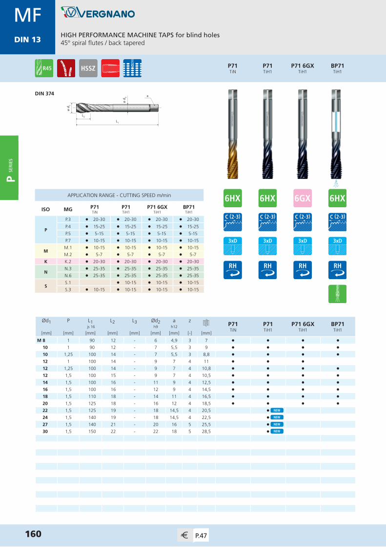
MDIN 13
HIGH PERFORMANCE MACHINE TAPS for blind holes45° spiral flutes / back tapered
160 P.47
MFDIN 13
ø d 1
L1
L2
ø d 2 a
Ød1 P L1 L2 L3 Ød2 a zP71TiN
P71TiH1
P71 6GXTiH1
BP71TiH1
js 16 h9 h12
[mm] [mm] [mm] [mm] [mm] [mm] [mm] [-] [mm]
M 8 1 90 12 - 6 4,9 3 7 • • • •10 1 90 12 - 7 5,5 3 9 • • • •10 1,25 100 14 - 7 5,5 3 8,8 • • • •12 1 100 14 - 9 7 4 11 • • •12 1,25 100 14 - 9 7 4 10,8 • • • •12 1,5 100 15 - 9 7 4 10,5 • • • •14 1,5 100 16 - 11 9 4 12,5 • • • •16 1,5 100 16 - 12 9 4 14,5 • • • •18 1,5 110 18 - 14 11 4 16,5 • • • •20 1,5 125 18 - 16 12 4 18,5 • • • •22 1,5 125 19 - 18 14,5 4 20,5 •24 1,5 140 19 - 18 14,5 4 22,5 •27 1,5 140 21 - 20 16 5 25,5 •30 1,5 150 22 - 22 18 5 28,5 •
APPLICATION RANGE - CUTTING SPEED m/min
ISO MG P71TiN
P71TiH1
P71 6GXTiH1
BP71TiH1
P
P.3 l 20-30 l 20-30 l 20-30 l 20-30
P.4 l 15-25 l 15-25 l 15-25 l 15-25
P.5 l 5-15 l 5-15 l 5-15 l 5-15
P.7 l 10-15 l 10-15 l 10-15 l 10-15
MM.1 l 10-15 l 10-15 l 10-15 l 10-15
M.2 l 5-7 l 5-7 l 5-7 l 5-7
K K.2 l 20-30 l 20-30 l 20-30 l 20-30
NN.3 l 25-35 l 25-35 l 25-35 l 25-35
N.6 l 25-35 l 25-35 l 25-35 l 25-35
SS.1 l 10-15 l 10-15 l 10-15
S.3 l 10-15 l 10-15 l 10-15 l 10-15
DIN 374
P71TiH1
P71TiN
P71 6GXTiH1
BP71TiH1
P SER
IES

MDIN 13
161P.47
HIGH PERFORMANCE MACHINE TAPS for blind holes45° spiral flutes / back tapered / chamfer form E
MFDIN 13
ø d 1
L1
L2
ø d 2 a
Ød1 P L1 L2 L3 Ød2 a zP71 E
TiH1 js 16 h9 h12
[mm] [mm] [mm] [mm] [mm] [mm] [mm] [-] [mm]
M 8 1 90 12 - 6 4,9 4 7 •10 1 90 12 - 7 5,5 4 9 •10 1,25 100 14 - 7 5,5 4 8,8 •12 1 100 14 - 9 7 4 11 •12 1,25 100 14 - 9 7 4 10,8 •12 1,5 100 15 - 9 7 4 10,5 •14 1,5 100 16 - 11 9 5 12,5 •16 1,5 100 16 - 12 9 5 14,5 •
APPLICATION RANGE - CUTTING SPEED m/min
ISO MG P71 ETiH1
P
P.3 l 20-30
P.4 l 15-25
P.5 l 5-15
P.7 l 10-15
MM.1 l 10-15
M.2 l 5-7
K K.2 l 20-30
NN.3 l 25-35
N.6 l 25-35
SS.1 l 10-15
S.3 l 10-15
DIN 374
P71 ETiH1
P SER
IES

MDIN 13
HIGH PERFORMANCE COLD FORMING TAPS for blind and through holesWithout oil grooves
162 P.47
MFDIN 13
Ød1 P L1 L2 L3 Ød2 a zP81TiN
P81V-MAXX
P81 6GXTiN
js 16 h9 h12
[mm] [mm] [mm] [mm] [mm] [mm] [mm] [-] [mm]
M 4 0,5 63 12 21 4,5 3,4 5 3,8 • • •5 0,5 70 14 24,5 6 4,9 5 4,8 • • •6 0,75 80 16 29 6 4,9 5 5,65 • • •8 1 90 18 33 8 6,2 5 7,55 • • •10 1 90 18 34 10 8 6 9,55 • • •10 1,25 100 20 36 10 8 6 9,4 • • •12 1 100 22 - 9 7 6 11,55 • • •12 1,25 100 22 - 9 7 6 11,4 • • •12 1,5 100 22 - 9 7 6 11,3 • • •14 1,25 100 22 - 11 9 6 13,4 • • •14 1,5 100 22 - 11 9 6 13,3 • • •16 1,5 100 22 - 12 9 6 15,3 • • •
APPLICATION RANGE - CUTTING SPEED m/min
ISO MG P81TiN
P81V-MAXX
P81 6GXTiN
P
P.1-2 l 40-45 l 40-45 l 40-45
P.3 l 35-40 l 35-40 l 35-40
P.4 l 30-35 l 30-35 l 30-35
P.5 l 15-20 l 15-20 l 15-20
P.7 l 15-20 l 15-20 l 15-20
M P.1 l 15-20 l 15-20 l 15-20
N
N.1-2 l 40-45 l 40-45 l 40-45
N.3 l 35-40 l 35-40 l 35-40
N.5-6 l 40-45 l 40-45 l 40-45
S S.3 l 10-15 l 10-15 l 10-15
P81V-MAXX
P81TiN
P81 6GXTiN
ø d 2
L1
L2
L3
ø d 1
a
ø d 1
L1
L2
ø d 2 a
DIN 2174 (371)≤ M10x1,25
DIN 2174 (374)≥ M12x1
P SER
IES
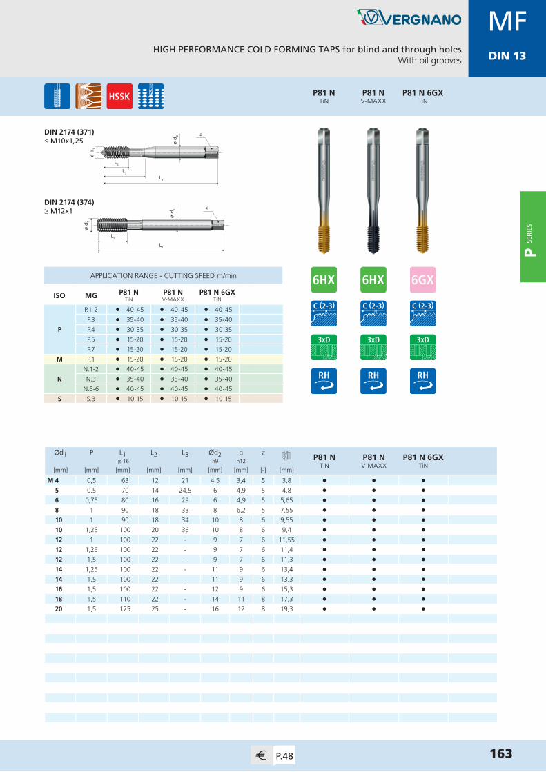
MDIN 13
HIGH PERFORMANCE COLD FORMING TAPS for blind and through holesWith oil grooves
163P.48
MFDIN 13
Ød1 P L1 L2 L3 Ød2 a zP81 N
TiNP81 NV-MAXX
P81 N 6GXTiN
js 16 h9 h12
[mm] [mm] [mm] [mm] [mm] [mm] [mm] [-] [mm]
M 4 0,5 63 12 21 4,5 3,4 5 3,8 • • •5 0,5 70 14 24,5 6 4,9 5 4,8 • • •6 0,75 80 16 29 6 4,9 5 5,65 • • •8 1 90 18 33 8 6,2 5 7,55 • • •10 1 90 18 34 10 8 6 9,55 • • •10 1,25 100 20 36 10 8 6 9,4 • • •12 1 100 22 - 9 7 6 11,55 • • •12 1,25 100 22 - 9 7 6 11,4 • • •12 1,5 100 22 - 9 7 6 11,3 • • •14 1,25 100 22 - 11 9 6 13,4 • • •14 1,5 100 22 - 11 9 6 13,3 • • •16 1,5 100 22 - 12 9 6 15,3 • • •18 1,5 110 22 - 14 11 8 17,3 • • •20 1,5 125 25 - 16 12 8 19,3 • • •
APPLICATION RANGE - CUTTING SPEED m/min
ISO MG P81 NTiN
P81 NV-MAXX
P81 N 6GXTiN
P
P.1-2 l 40-45 l 40-45 l 40-45
P.3 l 35-40 l 35-40 l 35-40
P.4 l 30-35 l 30-35 l 30-35
P.5 l 15-20 l 15-20 l 15-20
P.7 l 15-20 l 15-20 l 15-20
M P.1 l 15-20 l 15-20 l 15-20
N
N.1-2 l 40-45 l 40-45 l 40-45
N.3 l 35-40 l 35-40 l 35-40
N.5-6 l 40-45 l 40-45 l 40-45
S S.3 l 10-15 l 10-15 l 10-15
P81 NV-MAXX
P81 NTiN
P81 N 6GXTiN
ø d 2
L1
L2
L3
ø d 1
a
ø d 1
L1
L2
ø d 2 a
DIN 2174 (371)≤ M10x1,25
DIN 2174 (374)≥ M12x1
P SER
IES

MDIN 13
HIGH PERFORMANCE MACHINE TAPS for through holesStraight flutes with spiral point
164 P.48
ø d 1
L1
L2
ø d 2 a
P18TiH1
P18TiN
DIN 5156
GEN ISO 228
APPLICATION RANGE - CUTTING SPEED m/min
ISO MG P18TiN
P18TiH1
P
P.3 l 25-35 l 25-35
P.4 l 20-30 l 20-30
P.5 l 10-20 l 10-20
P.6 l 8-10 l 8-10
P.7 l 10-20 l 10-20
MM.1 l 10-20 l 10-20
M.2 l 6-8 l 6-8
K K.2 l 25-35 l 25-35
NN.2-3 l 30-40 l 30-40
N.6 l 25-35 l 25-35
P Ød1 L1 L2 L3 Ød2 a zP18TiN
P18TiH1
G js 16 h9 h12
[TPI] [mm] [mm] [mm] [mm] [mm] [mm] [-] [mm]
1/8” 28 9,728 90 18 - 7 5,5 3 8,8 • •1/4” 19 13,157 100 22 - 11 9 4 11,8 • •3/8” 19 16,662 100 22 - 12 9 4 15,25 • •1/2” 14 20,955 125 25 - 16 12 4 19 • •5/8” 14 22,911 125 25 - 18 14,5 4 21 • •3/4” 14 26,441 140 28 - 20 16 5 24,5 • •1” 11 33,249 160 30 - 25 20 5 30,75 • •
P SER
IES
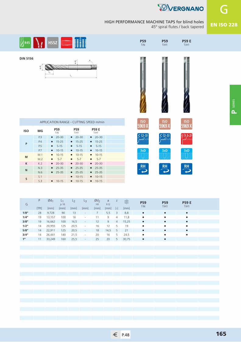
MDIN 13
165P.48
ø d 1
L1
L2
ø d 2 a
HIGH PERFORMANCE MACHINE TAPS for blind holes45° spiral flutes / back tapered
DIN 5156
GEN ISO 228
APPLICATION RANGE - CUTTING SPEED m/min
ISO MG P59TiN
P59TiH1
P59 ETiH1
P
P.3 l 20-30 l 20-30 l 20-30
P.4 l 15-25 l 15-25 l 15-25
P.5 l 5-15 l 5-15 l 5-15
P.7 l 10-15 l 10-15 l 10-15
MM.1 l 10-15 l 10-15 l 10-15
M.2 l 5-7 l 5-7 l 5-7
K K.2 l 20-30 l 20-30 l 20-30
NN.3 l 25-35 l 25-35 l 25-35
N.6 l 25-35 l 25-35 l 25-35
SS.1 l 10-15 l 10-15
S.3 l 10-15 l 10-15 l 10-15
P Ød1 L1 L2 L3 Ød2 a zP59TiN
P59TiH1
P59 ETiH1
G js 16 h9 h12
[TPI] [mm] [mm] [mm] [mm] [mm] [mm] [-] [mm]
1/8” 28 9,728 90 13 - 7 5,5 3 8,8 • • •1/4” 19 13,157 100 16 - 11 9 4 11,8 • • •3/8” 19 16,662 100 16,5 - 12 9 4 15,25 • • •1/2” 14 20,955 125 20,5 - 16 12 5 19 • • •5/8” 14 22,911 125 20,5 - 18 14,5 5 21 • • •3/4” 14 26,441 140 21,5 - 20 16 5 24,5 • • •1” 11 33,249 160 25,5 - 25 20 5 30,75 • •
P59TiH1
P59TiN
P59 ETiH1
P SER
IES
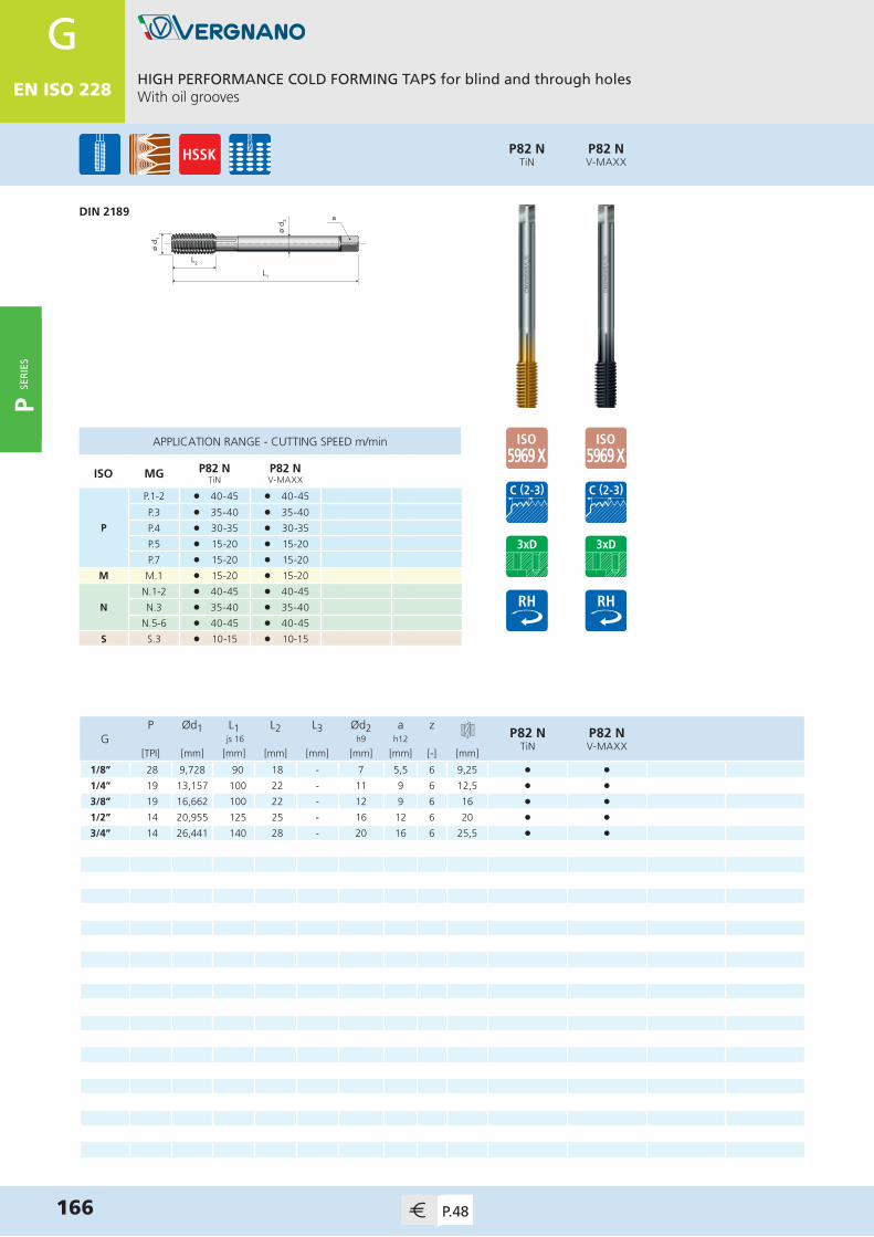
MDIN 13
HIGH PERFORMANCE COLD FORMING TAPS for blind and through holesWith oil grooves
166 P.48
ø d 1
L1
L2
ø d 2 a
P82 NV-MAXX
P82 NTiN
DIN 2189
GEN ISO 228
APPLICATION RANGE - CUTTING SPEED m/min
ISO MG P82 NTiN
P82 NV-MAXX
P
P.1-2 l 40-45 l 40-45
P.3 l 35-40 l 35-40
P.4 l 30-35 l 30-35
P.5 l 15-20 l 15-20
P.7 l 15-20 l 15-20
M M.1 l 15-20 l 15-20
N
N.1-2 l 40-45 l 40-45
N.3 l 35-40 l 35-40
N.5-6 l 40-45 l 40-45
S S.3 l 10-15 l 10-15
P Ød1 L1 L2 L3 Ød2 a zP82 N
TiNP82 NV-MAXX
G js 16 h9 h12
[TPI] [mm] [mm] [mm] [mm] [mm] [mm] [-] [mm]
1/8” 28 9,728 90 18 - 7 5,5 6 9,25 • •1/4” 19 13,157 100 22 - 11 9 6 12,5 • •3/8” 19 16,662 100 22 - 12 9 6 16 • •1/2” 14 20,955 125 25 - 16 12 6 20 • •3/4” 14 26,441 140 28 - 20 16 6 25,5 • •
P SER
IES

SS E R I E S
Synchronous Taps
S SE
RIE
S

MDIN 13
ø d 2
L1
L2
L3
ø d 1
a
ø d 1
L1
L2
ø d 2 a
Ød1 P L1 L2 L3 Ød2 a zS43
V-MAXXBS43
V-MAXXS43 E
V-MAXXBS43 EV-MAXX
js 16 h6 h12
[mm] [mm] [mm] [mm] [mm] [mm] [mm] [-] [mm]
M 3 0,5 70 5 15 6 4,9 3 2,5 •4 0,7 70 7 18 6 4,9 3 3,3 • •5 0,8 70 8 23 6 4,9 3 4,2 • • • •6 1 80 10 29 6 4,9 4 5 • • • •8 1,25 90 11 33 8 6,2 4 6,8 • • • •10 1,5 100 13 36 10 8 4 8,5 • • • •12 1,75 110 16 42 12 9 4 10,2 • • • •16 2 110 18 - 12 9 4 14 • • • •20 2,5 140 23 - 16 12 4 17,5 • • • •
BS43V-MAXX
S43V-MAXX
MACHINE TAPS FOR SYNCHRONOUS TAPPING for blind and through holesStraight flutes / for cast iron
~DIN 371≤ M12 (*)
~DIN 376≥ M16 (*)
168 P.49
MDIN 13
APPLICATION RANGE - CUTTING SPEED m/min
ISO MG S43V-MAXX
BS43V-MAXX
S43 EV-MAXX
BS43 EV-MAXX
K K.1 l 55-65 l 55-65 l 55-65 l 55-65
N
N.4 l 55-65 l 55-65 l 55-65 l 55-65
N.7 l 55-65 l 55-65 l 55-65 l 55-65
N.9-10 l 55-65 l 55-65 l 55-65 l 55-65
BS43 EV-MAXX
S43 EV-MAXX
(*) = DIN 1835-B on request
S SER
IES

MDIN 13
MACHINE TAPS FOR SYNCHRONOUS TAPPING for through holesStraight flutes with spiral point
169P.49
MDIN 13
ø d 2
L1
L2
L3
ø d 1
a
ø d 1
L1
L2
ø d 2 a
Ød1 P L1 L2 L3 Ød2 a zS15TiN
S15TiH1
BS15TiH1
js 16 h6 h12
[mm] [mm] [mm] [mm] [mm] [mm] [mm] [-] [mm]
M 3 0,5 70 5 15 6 4,9 3 2,5 • •4 0,7 70 7 18 6 4,9 3 3,3 • •5 0,8 70 8 25 6 4,9 3 4,2 • • •6 1 80 10 30 6 4,9 3 5 • • •8 1,25 90 12,5 35 8 6,2 3 6,8 • • •10 1,5 100 15 39 10 8 3 8,5 • • •12 1,75 110 17,5 42 12 9 3 10,2 • • •14 2 110 20 - 12 9 3 12 • •16 2 110 20 - 12 9 4 14 • • •
S15TiH1
S15TiN
APPLICATION RANGE - CUTTING SPEED m/min
ISO MG S15TiN
S15TiH1
BS15TiH1
P
P.1-2 l 50-60 l 50-60 l 50-60
P.3 l 45-55 l 45-55 l 45-55
P.4 l 40-50 l 40-50 l 40-50
P.5 l 15-25 l 15-25 l 15-25
P.7 l 15-25 l 15-25 l 15-25
MM.1 l 15-25 l 15-25 l 15-25
M.2 l 10-20 l 10-20 l 10-20
K K.2 l 45-55 l 45-55 l 45-55
N
N.1 l 50-60 l 50-60 l 50-60
N.2-3 l 45-55 l 45-55 l 45-55
N.5 l 40-50 l 40-50 l 40-50
N.6 l 35-45 l 35-45 l 35-45
SS.1 l 15-25 l 15-25
S.3 l 15-25 l 15-25 l 15-25
(*) = DIN 1835-B on request
BS15TiH1
~DIN 371≤ M12 (*)
~DIN 376≥ M14 (*)
S SE
RIE
S
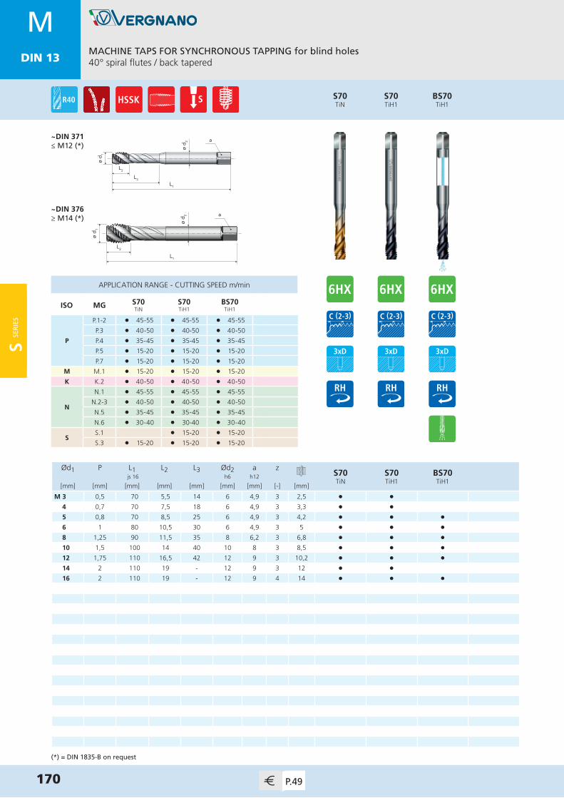
MDIN 13
MACHINE TAPS FOR SYNCHRONOUS TAPPING for blind holes40° spiral flutes / back tapered
170 P.49
MDIN 13
ø d 2
L1
L2
L3
ø d 1
a
ø d 1
L1
L2
ø d 2 a
Ød1 P L1 L2 L3 Ød2 a zS70TiN
S70TiH1
BS70TiH1
js 16 h6 h12
[mm] [mm] [mm] [mm] [mm] [mm] [mm] [-] [mm]
M 3 0,5 70 5,5 14 6 4,9 3 2,5 • •4 0,7 70 7,5 18 6 4,9 3 3,3 • •5 0,8 70 8,5 25 6 4,9 3 4,2 • • •6 1 80 10,5 30 6 4,9 3 5 • • •8 1,25 90 11,5 35 8 6,2 3 6,8 • • •10 1,5 100 14 40 10 8 3 8,5 • • •12 1,75 110 16,5 42 12 9 3 10,2 • • •14 2 110 19 - 12 9 3 12 • •16 2 110 19 - 12 9 4 14 • • •
S70TiH1
S70TiN
APPLICATION RANGE - CUTTING SPEED m/min
ISO MG S70TiN
S70TiH1
BS70TiH1
P
P.1-2 l 45-55 l 45-55 l 45-55
P.3 l 40-50 l 40-50 l 40-50
P.4 l 35-45 l 35-45 l 35-45
P.5 l 15-20 l 15-20 l 15-20
P.7 l 15-20 l 15-20 l 15-20
M M.1 l 15-20 l 15-20 l 15-20
K K.2 l 40-50 l 40-50 l 40-50
N
N.1 l 45-55 l 45-55 l 45-55
N.2-3 l 40-50 l 40-50 l 40-50
N.5 l 35-45 l 35-45 l 35-45
N.6 l 30-40 l 30-40 l 30-40
SS.1 l 15-20 l 15-20
S.3 l 15-20 l 15-20 l 15-20
(*) = DIN 1835-B on request
BS70TiH1
~DIN 371≤ M12 (*)
~DIN 376≥ M14 (*)
S SER
IES

MDIN 13
ø d 2
L1
L2
L3
ø d 1
a
Ød1 P L1 L2 L3 Ød2 a zS80 N
TiNS80 NV-MAXX
S80 N 6GXTiN
BS80 N RTiN
js 16 h6 h12
[mm] [mm] [mm] [mm] [mm] [mm] [mm] [-] [mm]
M 4 0,7 70 7 18 6 4,9 5 3,7 • • • •5 0,8 70 8 23 6 4,9 5 4,65 • • • •6 1 80 10 29 6 4,9 5 5,55 • • • •8 1,25 90 11 33 8 6,2 5 7,4 • • • •10 1,5 100 13 36 10 8 5 9,3 • • • •12 1,75 110 16 42 12 9 5 11,2 • • • •
BS80 N RTiN
S80 N 6GXTiN
S80 NV-MAXX
S80 NTiN
COLD FORMING TAPS FOR SYNCHRONOUS TAPPING for blind and through holesWith oil grooves
171P.49
MDIN 13
APPLICATION RANGE - CUTTING SPEED m/min
ISO MG S80 NTiN
S80 NV-MAXX
S80 N 6GXTiN
BS80 N RTiN
P
P.1-2 l 50-60 l 50-60 l 50-60 l 50-60
P.3 l 45-55 l 45-55 l 45-55 l 45-55
P.4 l 40-50 l 40-50 l 40-50 l 40-50
P.5 l 20-30 l 20-30 l 20-30 l 20-30
P.7 l 25-35 l 25-35 l 25-35 l 25-35
MM.1 l 25-35 l 25-35 l 25-35 l 25-35
M.2 l 15-25 l 15-25 l 15-25 l 15-25
N
N.1-2 l 50-60 l 50-60 l 50-60 l 50-60
N.3 l 45-55 l 45-55 l 45-55 l 45-55
N.5-6 l 50-60 l 50-60 l 50-60 l 50-60
S S.3 l 10-20 l 10-20 l 10-20 l 10-20
~DIN 371 (*)
(*) = DIN 1835-B on request
S SE
RIE
S
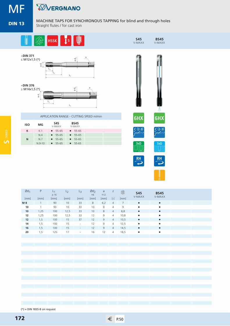
MDIN 13
ø d 2
L1
L2
L3
ø d 1
a
ø d 1
L1
L2
ø d 2 a
Ød1 P L1 L2 L3 Ød2 a zS45
V-MAXXBS45
V-MAXX js 16 h6 h12
[mm] [mm] [mm] [mm] [mm] [mm] [mm] [-] [mm]
M 8 1 90 10 33 8 6,2 4 7 • •10 1 90 10 33 10 8 4 9 • •10 1,25 100 12,5 33 10 8 4 8,8 • •12 1,25 100 12,5 33 12 9 4 10,8 • •12 1,5 100 15 37 12 9 4 10,5 • •14 1,5 100 15 - 12 9 4 12,5 • •16 1,5 100 15 - 12 9 4 14,5 • •20 1,5 125 17 - 16 12 4 18,5 • •
APPLICATION RANGE - CUTTING SPEED m/min
ISO MG S45V-MAXX
BS45V-MAXX
K K.1 l 55-65 l 55-65
N
N.4 l 55-65 l 55-65
N.7 l 55-65 l 55-65
N.9-10 l 55-65 l 55-65
MACHINE TAPS FOR SYNCHRONOUS TAPPING for blind and through holesStraight flutes / for cast iron
172 P.50
MFDIN 13
BS45V-MAXX
S45V-MAXX
~DIN 371≤ M12x1,5 (*)
~DIN 376≥ M14x1,5 (*)
(*) = DIN 1835-B on request
S SER
IES

MDIN 13
MACHINE TAPS FOR SYNCHRONOUS TAPPING for through holesStraight flutes with spiral point
173P.50
MFDIN 13
ø d 2
L1
L2
L3
ø d 1
a
ø d 1
L1
L2
ø d 2 a
Ød1 P L1 L2 L3 Ød2 a zS17TiN
js 16 h6 h12
[mm] [mm] [mm] [mm] [mm] [mm] [mm] [-] [mm]
M 8 1 90 10 35 8 6,2 3 7 •10 1 90 10 39 10 8 3 9 •10 1,25 100 12,5 39 10 8 3 8,8 •12 1,25 100 12,5 42 12 9 3 10,8 •12 1,5 100 15 42 12 9 3 10,5 •14 1,5 100 15 - 12 9 3 12,5 •16 1,5 100 15 - 12 9 4 14,5 •
S17TiN
APPLICATION RANGE - CUTTING SPEED m/min
ISO MG S17TiN
P
P.1-2 l 50-60
P.3 l 45-55
P.4 l 40-50
P.5 l 15-25
P.7 l 15-25
MM.1 l 15-25
M.2 l 10-20
K K.2 l 45-55
N
N.1 l 50-60
N.2-3 l 45-55
N.5 l 40-50
N.6 l 35-45
S.3 l 15-25
(*) = DIN 1835-B on request
~DIN 371≤ M12x1,5 (*)
~DIN 376≥ M14x1,5 (*)
S SE
RIE
S

MDIN 13
MACHINE TAPS FOR SYNCHRONOUS TAPPING for blind holes40° spiral flutes / back tapered
174 P.50
MFDIN 13
ø d 2
L1
L2
L3
ø d 1
a
ø d 1
L1
L2
ø d 2 a
Ød1 P L1 L2 L3 Ød2 a zS71TiN
js 16 h6 h12
[mm] [mm] [mm] [mm] [mm] [mm] [mm] [-] [mm]
M 8 1 90 10 35 8 6,2 3 7 •10 1 90 10 40 10 8 3 9 •10 1,25 100 11,5 40 10 8 3 8,8 •12 1,25 100 11,5 40 12 9 3 10,8 •12 1,5 100 14 42 12 9 3 10,5 •14 1,5 100 14 - 12 9 4 12,5 •16 1,5 100 14 - 12 9 4 14,5 •
APPLICATION RANGE - CUTTING SPEED m/min
ISO MG S71TiN
P
P.1-2 l 45-55
P.3 l 40-50
P.4 l 35-45
P.5 l 15-20
P.7 l 15-20
M M.1 l 15-20
K K.2 l 40-50
N
N.1 l 45-55
N.2-3 l 40-50
N.5 l 35-45
N.6 l 30-40
S S.3 l 15-20
S71TiN
~DIN 371≤ M12x1,5 (*)
~DIN 376≥ M14x1,5 (*)
(*) = DIN 1835-B on request
S SER
IES

HS E R I E S
Solid Carbide Taps
H SE
RIE
S

ø d 2
L1
L2
L3
ø d 1
a
Ød1 P L1 L2 L3 Ød2 a zHB43BRIGHT
HB43V-MAXX
HB43 EV-MAXX
js 16 h6 h12
[mm] [mm] [mm] [mm] [mm] [mm] [mm] [-] [mm]
M 3(*) 0,5 56 8 18 3,5 2,7 3 2,5 • •4(*) 0,7 63 10 21 4,5 3,4 4 3,3 • •5 0,8 70 10 25 6 4,9 4 4,2 • • •6 1 80 12 30 6 4,9 4 5 • • •8 1,25 90 16 35 8 6,2 4 6,8 • • •10 1,5 100 18 39 10 8 4 8,5 • • •
APPLICATION RANGE - CUTTING SPEED m/min
ISO MG HB43BRIGHT
HB43V-MAXX
HB43 EV-MAXX
K K.1 l 40-50 l 55-65 l 55-65
N
N.4 l 40-50 l 55-65 l 55-65
N.7 l 40-50 l 55-65 l 55-65
N.9-10 l 45-55 l 55-65 l 55-65
SOLID CARBIDE MACHINE TAPS for blind holesStraight flutes / internal coolant / for cast iron
176 P.51
MDIN 13
HB43V-MAXX
HB43BRIGHT
DIN 371
HB43 EV-MAXX
(*) = Taps without through coolant
H SE
RIE
S
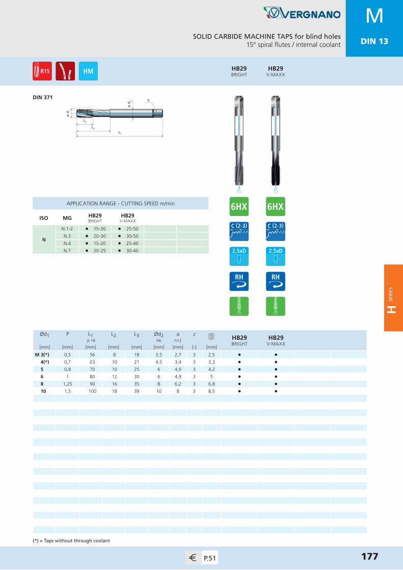
SOLID CARBIDE MACHINE TAPS for blind holes15° spiral flutes / internal coolant
177P.51
MDIN 13
ø d 2
L1
L2
L3
ø d 1
a
Ød1 P L1 L2 L3 Ød2 a zHB29BRIGHT
HB29V-MAXX
js 16 h6 h12
[mm] [mm] [mm] [mm] [mm] [mm] [mm] [-] [mm]
M 3(*) 0,5 56 8 18 3,5 2,7 3 2,5 • •4(*) 0,7 63 10 21 4,5 3,4 3 3,3 • •5 0,8 70 10 25 6 4,9 3 4,2 • •6 1 80 12 30 6 4,9 3 5 • •8 1,25 90 16 35 8 6,2 3 6,8 • •10 1,5 100 18 39 10 8 3 8,5 • •
APPLICATION RANGE - CUTTING SPEED m/min
ISO MG HB29BRIGHT
HB29V-MAXX
N
N.1-2 l 15-30 l 25-50
N.3 l 20-30 l 30-50
N.4 l 15-20 l 25-40
N.7 l 20-25 l 30-40
(*) = Taps without through coolant
DIN 371
HB29V-MAXX
HB29BRIGHT
H SE
RIE
S
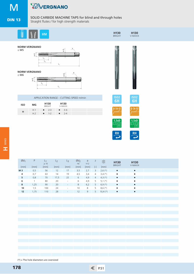
ø d 2
L1
L3
L2
ø d 1
a
Ød1 P L1 L2 L3 Ød2 a zH130BRIGHT
H130V-MAXX
js 16 h6 h12
[mm] [mm] [mm] [mm] [mm] [mm] [mm] [-] [mm]
M 3 0,5 56 12 17 3,5 2,7 3 2,6 (*) • •4 0,7 63 14 19 4,5 3,4 4 3,4 (*) • •5 0,8 70 17,5 22 6 4,9 4 4,3 (*) • •6 1 80 20 - 6 4,9 5 5,1 (*) • •8 1,25 90 20 - 8 6,2 5 6,9 (*) • •10 1,5 100 24 - 10 8 5 8,6 (*) • •12 1,75 110 28 - 12 9 5 10,4 (*) • •
APPLICATION RANGE - CUTTING SPEED m/min
ISO MG H130BRIGHT
H130V-MAXX
HH.1 l 2-3 l 3-6
H.2 l 1-2 l 2-4
SOLID CARBIDE MACHINE TAPS for blind and through holesStraight flutes / for high strength materials
178 P.51
MDIN 13
H130V-MAXX
H130BRIGHT
(*) = The hole diameters are oversized
ø d 2
L1
L2
ø d 1
aNORM VERGNANO≥ M6
NORM VERGNANO≤ M5
H SE
RIE
S

SOLID CARBIDE COLD FORMING TAPS for blind and through holesWith oil grooves / internal coolant
179P.51
MDIN 13
ø d 2
L2
ø d 1
a
L1
L3
Ød1 P L1 L2 L3 Ød2 a zHB80 N R
V-MAXX js 16 h6 h12
[mm] [mm] [mm] [mm] [mm] [mm] [mm] [-] [mm]
M 3(*) 0,5 56 6 18 3,5 2,7 4 2,8 •4(*) 0,7 63 7,5 21 4,5 3,4 5 3,7 •5 0,8 70 8,5 25 6 4,9 5 4,65 •6 1 80 11 30 6 4,9 5 5,55 •8 1,25 90 14 35 8 6,2 5 7,4 •10 1,5 100 16 39 10 8 5 9,3 •
(*) = Taps without through coolant
DIN 371
HB80 N RV-MAXX
APPLICATION RANGE - CUTTING SPEED m/min
ISO MG HB80 N RV-MAXX
P
P.1-2 l 40-50
P.3 l 35-45
P.4 l 30-40
P.5 l 15-25
P.7 l 15-25
M M.1 l 15-25
N
N.1-2 l 40-50
N.3 l 35-45
N.5-6 l 40-50
S S.3 l 10-20
H SE
RIE
S

ø d 1
L1
L2
ø d 2 a
Ød1 P L1 L2 L3 Ød2 a zHB45BRIGHT
HB45V-MAXX
HB45 EV-MAXX
js 16 h6 h12
[mm] [mm] [mm] [mm] [mm] [mm] [mm] [-] [mm]
M 10 1 90 18 - 7 5,5 4 9 • • •12 1,25 100 22 - 9 7 4 10,8 • • •12 1,5 100 22 - 9 7 4 10,5 • • •14 1,5 100 22 - 11 9 4 12,5 • • •16 1,5 100 22 - 12 9 4 14,5 • • •
HB45 EV-MAXX
SOLID CARBIDE MACHINE TAPS for blind holesStraight flutes / internal coolant / for cast iron
180 P.52
MFDIN 13
HB45V-MAXX
HB45BRIGHT
DIN 374
APPLICATION RANGE - CUTTING SPEED m/min
ISO MG HB45BRIGHT
HB45V-MAXX
HB45 EV-MAXX
K K.1 l 40-50 l 55-65 l 55-65
N
N.4 l 40-50 l 55-65 l 55-65
N.7 l 40-50 l 55-65 l 55-65
N.9-10 l 45-55 l 55-65 l 55-65
H SE
RIE
S
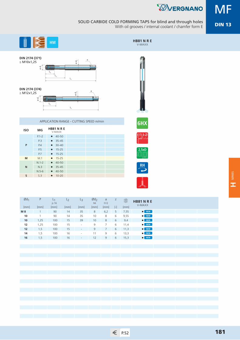
SOLID CARBIDE COLD FORMING TAPS for blind and through holesWith oil grooves / internal coolant / chamfer form E
181P.52
MFDIN 13
ø d 2
L2
ø d 1
a
L1
L3
Ød1 P L1 L2 L3 Ød2 a zHB81 N R E
V-MAXX js 16 h6 h12
[mm] [mm] [mm] [mm] [mm] [mm] [mm] [-] [mm]
M 8 1 90 14 35 8 6,2 5 7,55 •10 1 90 14 35 10 8 6 9,55 •10 1,25 100 15 39 10 8 6 9,4 •12 1,25 100 15 - 9 7 6 11,4 •12 1,5 100 15 - 9 7 6 11,3 •14 1,5 100 16 - 11 9 6 13,3 •16 1,5 100 16 - 12 9 6 15,3 •
DIN 2174 (371)≤ M10x1,25
HB81 N R EV-MAXX
APPLICATION RANGE - CUTTING SPEED m/min
ISO MG HB81 N R EV-MAXX
P
P.1-2 l 40-50
P.3 l 35-45
P.4 l 30-40
P.5 l 15-25
P.7 l 15-25
M M.1 l 15-25
N
N.1-2 l 40-50
N.3 l 35-45
N.5-6 l 40-50
S S.3 l 10-20
ø d 1
L1
L2
ø d 2 aDIN 2174 (374)
≥ M12x1,25
H SE
RIE
S

E
Discontinued Taps E

MDIN 13
ø d 2
L1
L2
L3
ø d 1
a
ø d 1
L1
L2
ø d 2 a
Ød1 P L1 L2 L3 Ød2 a zA21 FC LH
BRIGHT js 16 h9 h12
[mm] [mm] [mm] [mm] [mm] [mm] [mm] [-] [mm]
M 3 0,5 56 10 18 3,5 2,7 3 2,5 •4 0,7 63 12 21 4,5 3,4 3 3,3 •5 0,8 70 14 24,5 6 4,9 3 4,2 •6 1 80 16 29 6 4,9 3 5 •8 1,25 90 18 33 8 6,2 3 6,8 • 10 1,5 100 20 36 10 8 3 8,5 •12 1,75 110 24 - 9 7 3 10,2 •14 2 110 25 - 11 9 3 12 •16 2 110 28 - 12 9 3 14 •18 2,5 125 32 - 14 11 3 15,5 •20 2,5 140 32 - 16 12 4 17,5 •22 2,5 140 32 - 18 14,5 4 19,5 •24 3 160 36 - 18 14,5 4 21 •27 3 160 36 - 20 16 4 24 •30 3,5 180 40 - 22 18 4 26,5 •
A21 FC LHBRIGHT
MACHINE TAPS for blind holesStraight flutes
DIN 371≤ M10
DIN 376≥ M12
184 P.53
MDIN 13
ARTICLE SUBSTITUTED WITH
A70S LH(pp. 66)
E

MDIN 13
MACHINE TAPS for through holesStraight flutes
185P.53
MDIN 13
ø d 2
L1
L2
L3
ø d 1
a
ø d 1
L1
L2
ø d 2 a
Ød1 P L1 L2 L3 Ød2 a zA21 FPBRIGHT
A21 FPTiN
js 16 h9 h12
[mm] [mm] [mm] [mm] [mm] [mm] [mm] [-] [mm]
M 2 0,4 45 7 11 2,8 2,1 3 1,6 • •2,2 0,45 45 8 13 2,8 2,1 3 1,75 • •2,3 0,4 45 8 13 2,8 2,1 3 1,9 • •2,5 0,45 50 9 15 2,8 2,1 3 2,05 • •2,6 0,45 50 9 15 2,8 2,1 3 2,1 • •3 0,5 56 10 18 3,5 2,7 3 2,5 • •3,5 0,6 56 11 20 4 3 3 2,9 • •4 0,7 63 12 21 4,5 3,4 3 3,3 • •5 0,8 70 14 24,5 6 4,9 3 4,2 • •6 1 80 16 29 6 4,9 3 5 • •7 1 80 16 29 7 5,5 3 6 • •8 1,25 90 18 33 8 6,2 3 6,8 • •9 1,25 90 18 33 9 7 3 7,8 • •10 1,5 100 20 36 10 8 3 8,5 • •11 1,5 100 22 - 8 6,2 3 9,5 • •12 1,75 110 24 - 9 7 3 10,2 • •14 2 110 25 - 11 9 3 12 • •16 2 110 28 - 12 9 3 14 • •18 2,5 125 32 - 14 11 3 15,5 • •20 2,5 140 32 - 16 12 4 17,5 • •22 2,5 140 32 - 18 14,5 4 19,5 • •24 3 160 36 - 18 14,5 4 21 • •27 3 160 36 - 20 16 4 24 • •30 3,5 180 40 - 22 18 4 26,5 • •33 3,5 180 40 - 25 20 4 29,5 • •36 4 200 55 - 28 22 4 32 • •
A21 FPTiN
A21 FPBRIGHT
DIN 371≤ M10
DIN 376≥ M11
ARTICLE SUBSTITUTED WITH
A15 S(pp. 45)
»
E
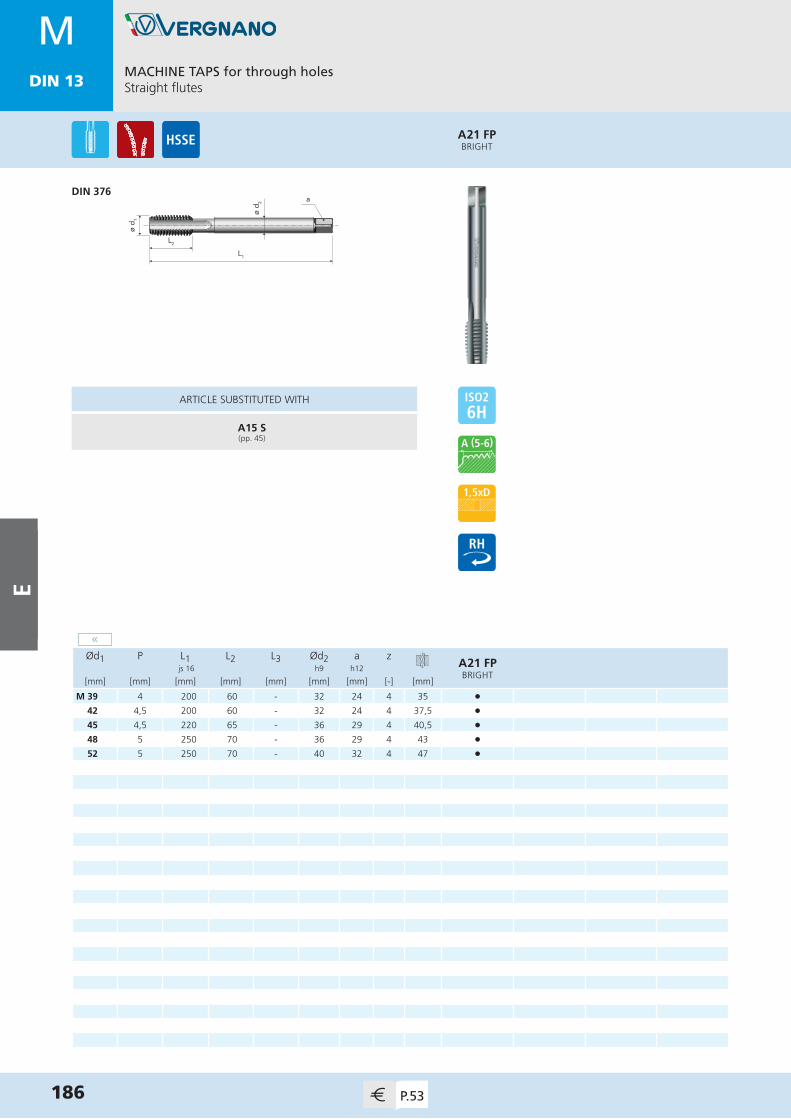
MDIN 13
MACHINE TAPS for through holesStraight flutes
186 P.53
MDIN 13
ø d 1
L1
L2
ø d 2 a
Ød1 P L1 L2 L3 Ød2 a zA21 FPBRIGHT
js 16 h9 h12
[mm] [mm] [mm] [mm] [mm] [mm] [mm] [-] [mm]
M 39 4 200 60 - 32 24 4 35 •42 4,5 200 60 - 32 24 4 37,5 •45 4,5 220 65 - 36 29 4 40,5 •48 5 250 70 - 36 29 4 43 •52 5 250 70 - 40 32 4 47 •
A21 FPBRIGHT
DIN 376
ARTICLE SUBSTITUTED WITH
A15 S(pp. 45)
«
E

MDIN 13
MACHINE TAPS for through holesStraight flutes / through shank
187P.54
MDIN 13
ø d 2
L1
L2
ø d 1
a
Ød1 P L1 L2 L3 Ød2 a zA22 FPBRIGHT
A22 FPTiN
js 16 h9 h12
[mm] [mm] [mm] [mm] [mm] [mm] [mm] [-] [mm]
M 4 0,7 63 12 - 2,8 2,1 3 3,3 • •5 0,8 70 14 - 3,5 2,7 3 4,2 • •6 1 80 16 - 4,5 3,4 3 5 • •7 1 80 16 - 5,5 4,3 3 6 • •8 1,25 90 18 - 6 4,9 3 6,8 • •9 1,25 90 18 - 7 5,5 3 7,8 • •10 1,5 100 20 - 7 5,5 3 8,5 • •
A22 FPTiN
A22 FPBRIGHT
DIN 376
ARTICLE SUBSTITUTED WITH
A16 S(pp. 51)
E
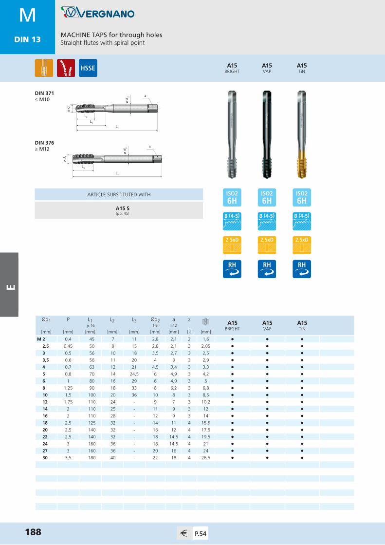
MDIN 13
MACHINE TAPS for through holesStraight flutes with spiral point
188 P.54
MDIN 13
Ød1 P L1 L2 L3 Ød2 a zA15
BRIGHTA15VAP
A15TiN
js 16 h9 h12
[mm] [mm] [mm] [mm] [mm] [mm] [mm] [-] [mm]
M 2 0,4 45 7 11 2,8 2,1 2 1,6 • • •2,5 0,45 50 9 15 2,8 2,1 3 2,05 • • •3 0,5 56 10 18 3,5 2,7 3 2,5 • • •3,5 0,6 56 11 20 4 3 3 2,9 • • •4 0,7 63 12 21 4,5 3,4 3 3,3 • • •5 0,8 70 14 24,5 6 4,9 3 4,2 • • •6 1 80 16 29 6 4,9 3 5 • • •8 1,25 90 18 33 8 6,2 3 6,8 • • •10 1,5 100 20 36 10 8 3 8,5 • • •12 1,75 110 24 - 9 7 3 10,2 • • •14 2 110 25 - 11 9 3 12 • • •16 2 110 28 - 12 9 3 14 • • •18 2,5 125 32 - 14 11 4 15,5 • • •20 2,5 140 32 - 16 12 4 17,5 • • •22 2,5 140 32 - 18 14,5 4 19,5 • • •24 3 160 36 - 18 14,5 4 21 • • •27 3 160 36 - 20 16 4 24 • • •30 3,5 180 40 - 22 18 4 26,5 • • •
A15BRIGHT
A15VAP
A15TiN
ø d 2
L1
L2
L3
ø d 1
a
ø d 1
L1
L2
ø d 2 a
DIN 371≤ M10
DIN 376≥ M12
ARTICLE SUBSTITUTED WITH
A15 S(pp. 45)
E

MDIN 13
MACHINE TAPS for through holesStraight flutes with spiral point
189P.54
MDIN 13
Ød1 P L1 L2 L3 Ød2 a zA15 6GBRIGHT
A15 6GTiN
js 16 h9 h12
[mm] [mm] [mm] [mm] [mm] [mm] [mm] [-] [mm]
M 2 0,4 45 7 11 2,8 2,1 2 1,6 • •2,5 0,45 50 9 15 2,8 2,1 3 2,05 • •3 0,5 56 10 18 3,5 2,7 3 2,5 • •4 0,7 63 12 21 4,5 3,4 3 3,3 • •5 0,8 70 14 24,5 6 4,9 3 4,2 • •6 1 80 16 29 6 4,9 3 5 • •8 1,25 90 18 33 8 6,2 3 6,8 • •10 1,5 100 20 36 10 8 3 8,5 • •12 1,75 110 24 - 9 7 3 10,2 • •14 2 110 25 - 11 9 3 12 • •16 2 110 28 - 12 9 3 14 • •
A15 6GBRIGHT
A15 6GTiN
ø d 2
L1
L2
L3
ø d 1
a
ø d 1
L1
L2
ø d 2 a
DIN 371≤ M10
DIN 376≥ M12
ARTICLE SUBSTITUTED WITH
A15 S 6G(pp. 48)
E

MDIN 13
MACHINE TAPS for blind holes40° spiral flutes / back tapered
190 P.55
MDIN 13
Ød1 P L1 L2 L3 Ød2 a zA70
BRIGHTA70VAP
A70TiN
js 16 h9 h12
[mm] [mm] [mm] [mm] [mm] [mm] [mm] [-] [mm]
M 2 0,4 45 6 12 2,8 2,1 3 1,6 • • •2,5 0,45 50 6,5 15 2,8 2,1 3 2,05 • • •3 0,5 56 7 15 3,5 2,7 3 2,5 • • •4 0,7 63 8,5 21 4,5 3,4 3 3,3 • • •5 0,8 70 10 24,5 6 4,9 3 4,2 • • •6 1 80 12 29 6 4,9 3 5 • • •8 1,25 90 15 33 8 6,2 3 6,8 • • •10 1,5 100 17,5 38 10 8 3 8,5 • • •12 1,75 110 18 - 9 7 4 10,2 • • •14 2 110 20,5 - 11 9 4 12 • • •16 2 110 20,5 - 12 9 4 14 • • •18 2,5 125 25,5 - 14 11 4 15,5 • • •20 2,5 140 29,5 - 16 12 4 17,5 • • •22 2,5 140 29,5 - 18 14,5 4 19,5 • • •24 3 160 35,5 - 18 14,5 4 21 • • •27 3 160 37,5 - 20 16 4 24 • • •30 3,5 180 42 - 22 18 4 26,5 • • •33 3,5 180 43,5 - 25 20 4 29,5 • • •36 4 200 47 - 28 22 4 32 • • •
A70BRIGHT
A70VAP
A70TiN
ø d 2
L1
L2
L3
ø d 1
a
ø d 1
L2
ø d 2 a
L1
DIN 371≤ M10
DIN 376≥ M12
ARTICLE SUBSTITUTED WITH
A70 S(pp. 60)
E

MACHINE TAPS for blind holes40° spiral flutes / back tapered
191P.55
MDIN 13
Ød1 P L1 L2 L3 Ød2 a zA70 6GBRIGHT
A70 6GVAP
A70 6GTiN
js 16 h9 h12
[mm] [mm] [mm] [mm] [mm] [mm] [mm] [-] [mm]
M 2 0,4 45 6 12 2,8 2,1 3 1,6 • • •2,5 0,45 50 6,5 15 2,8 2,1 3 2,05 • • •3 0,5 56 7 15 3,5 2,7 3 2,5 • • •4 0,7 63 8,5 21 4,5 3,4 3 3,3 • • •5 0,8 70 10 24,5 6 4,9 3 4,2 • • •6 1 80 12 29 6 4,9 3 5 • • •8 1,25 90 15 33 8 6,2 3 6,8 • • •10 1,5 100 17,5 38 10 8 3 8,5 • • •12 1,75 110 18 - 9 7 4 10,2 • • •
A70 6GBRIGHT
A70 6GVAP
A70 6GTiN
ø d 2
L1
L2
L3
ø d 1
a
ø d 1
L2
ø d 2 a
L1
DIN 371≤ M10
DIN 376≥ M12
ARTICLE SUBSTITUTED WITH
A70 S 6G(pp. 62)
E

MACHINE TAPS for through holesStraight flutes
192 P.55
MFDIN 13
Ød1 P L1 L2 L3 Ød2 a zA23 FPBRIGHT
A23 FPTiN
A23 FP LHBRIGHT
js 16 h9 h12
[mm] [mm] [mm] [mm] [mm] [mm] [mm] [-] [mm]
M 3 0,35 56 8 - 2,2 - 3 2,65 •3,5 0,35 56 9 - 2,5 2,1 3 3,15 •4 0,5 63 10 - 2,8 2,1 3 3,5 •5 0,5 70 12 - 3,5 2,7 3 4,5 •6 0,5 80 14 - 4,5 3,4 3 5,5 • •6 0,75 80 14 - 4,5 3,4 3 5,2 • • •7 0,75 80 14 - 5,5 4,3 3 6,2 • •8 0,75 80 16 - 6 4,9 3 7,2 •8 1 90 16 - 6 4,9 3 7 • • •9 1 90 16 - 7 5,5 3 8 •10 0,5 90 18 - 7 5,5 4 9,5 • •10 0,75 90 18 - 7 5,5 3 9,2 •10 1 90 18 - 7 5,5 3 9 • • •10 1,25 100 18 - 7 5,5 3 8,8 • • •11 1 90 20 - 8 6,2 3 10 •12 0,75 100 22 - 9 7 4 11,2 • •12 1 100 22 - 9 7 4 11 • •12 1,25 100 22 - 9 7 3 10,8 • • •12 1,5 100 22 - 9 7 3 10,5 • • •14 1 100 22 - 11 9 4 13 • •14 1,25 100 22 - 11 9 3 12,8 • •14 1,5 100 22 - 11 9 3 12,5 • • •15 1 100 22 - 12 9 4 14 •15 1,5 100 22 - 12 9 3 13,5 •16 1 100 22 - 12 9 4 15 • •16 1,25 100 22 - 12 9 4 14,8 • •
A23 FPBRIGHT
A23 FPTiN
ø d 1
L1
L2
ø d 2 aDIN 374
»
A23 FP LHBRIGHT
A23 FPBRIGHT
A23 FPTiN
A23 FP LHBRIGHT
ARTICLE SUBSTITUTED WITH
A17 S(pp. 87)
A17 S(pp. 87)
A23 FC LH(pp. 83)
E

MACHINE TAPS for through holesStraight flutes
193P.56
MFDIN 13
Ød1 P L1 L2 L3 Ød2 a zA23 FPBRIGHT
A23 FPTiN
A23 FP LHBRIGHT
js 16 h9 h12
[mm] [mm] [mm] [mm] [mm] [mm] [mm] [-] [mm]
M 16 1,5 100 22 - 12 9 3 14,5 • • •17 1 100 22 - 12 9 4 16 •17 1,5 100 22 - 12 9 4 15,5 •18 1 110 25 - 14 11 4 17 •18 1,5 110 25 - 14 11 4 16,5 • • •18 2 125 28 - 14 11 4 16 •20 1 125 25 - 16 12 4 19 •20 1,5 125 25 - 16 12 4 18,5 • • •20 2 140 28 - 16 12 4 18 •22 1 125 25 - 18 14,5 4 21 •22 1,5 125 25 - 18 14,5 4 20,5 • •22 2 140 28 - 18 14,5 4 20 •24 1 140 25 - 18 14,5 4 23 •24 1,5 140 25 - 18 14,5 4 22,5 •24 2 140 28 - 18 14,5 4 22 •25 1 140 25 - 18 14,5 4 24 •25 1,5 140 25 - 18 14,5 4 23,5 •25 2 140 28 - 18 14,5 4 23 •26 1 140 25 - 18 14,5 4 25 •26 1,5 140 25 - 18 14,5 4 24,5 •26 2 140 28 - 18 14,5 4 24 •27 1,5 140 28 - 20 16 4 25,5 •27 2 140 28 - 20 16 4 25 •28 1,5 140 28 - 20 16 4 26,5 •28 2 140 28 - 20 16 4 26 •30 1 150 25 - 22 18 5 29 •
A23 FPBRIGHT
A23 FPTiN
ø d 1
L1
L2
ø d 2 aDIN 374
«
»
A23 FP LHBRIGHT
A23 FPBRIGHT
A23 FPTiN
A23 FP LHBRIGHT
ARTICLE SUBSTITUTED WITH
A17 S(pp. 87)
A17 S(pp. 87)
A23 FC LH(pp. 84)
E

MACHINE TAPS for through holesStraight flutes
194 P.56
MFDIN 13
A23 FPBRIGHT
ø d 1
L1
L2
ø d 2 aDIN 374
Ød1 P L1 L2 L3 Ød2 a zA23 FPBRIGHT
js 16 h9 h12
[mm] [mm] [mm] [mm] [mm] [mm] [mm] [-] [mm]
M 30 1,5 150 28 - 22 18 4 28,5 •30 2 150 28 - 22 18 4 28 •32 1,5 150 28 - 22 18 5 30,5 •32 2 150 28 - 22 18 4 30 •33 1,5 160 30 - 25 20 5 31,5 •33 2 160 30 - 25 20 4 31 •35 1,5 170 30 - 28 22 5 33,5 •35 2 170 30 - 28 22 5 33 •36 1,5 170 30 - 28 22 5 34,5 •36 2 170 30 - 28 22 5 34 •36 3 200 56 - 28 22 4 33 •39 3 200 60 - 32 24 5 36 •40 1,5 170 30 - 32 24 5 38,5 •40 2 170 30 - 32 24 5 38 •40 3 200 60 - 32 24 5 37 •42 1,5 170 30 - 32 24 6 40,5 •42 2 170 30 - 32 24 5 40 •42 3 200 60 - 32 24 5 39 •45 1,5 180 32 - 36 29 6 43,5 •45 2 180 32 - 36 29 5 43 •45 3 200 50 - 36 29 5 42 •48 1,5 190 32 - 36 29 6 46,5 •48 2 190 32 - 36 29 6 46 •48 3 225 50 - 36 29 5 45 •52 1,5 190 32 - 40 32 6 50,5 •52 2 190 32 - 40 32 6 50 •52 3 225 50 - 40 32 5 49 •
ARTICLE SUBSTITUTED WITH
A17 S(pp. 88-89)
«
E

MACHINE TAPS for through holesStraight flutes with spiral point
195P.57
MFDIN 13
Ød1 P L1 L2 L3 Ød2 a zA17
BRIGHTA17VAP
A17TiN
js 16 h9 h12
[mm] [mm] [mm] [mm] [mm] [mm] [mm] [-] [mm]
M 4 0,5 63 10 - 2,8 2,1 3 3,5 •5 0,5 70 12 - 3,5 2,7 3 4,5 •6 0,75 80 14 - 4,5 3,4 3 5,2 • • •7 0,75 80 14 - 5,5 4,3 3 6,2 •8 0,75 80 16 - 6 4,9 3 7,2 •8 1 90 16 - 6 4,9 3 7 • • •9 1 90 16 - 7 5,5 3 8 •10 0,75 90 18 - 7 5,5 4 9,2 •10 1 90 18 - 7 5,5 4 9 • • •10 1,25 100 18 - 7 5,5 3 8,8 • • •11 1 90 20 - 8 6,2 4 10 •12 1 100 22 - 9 7 4 11 • • •12 1,25 100 22 - 9 7 4 10,8 • • •12 1,5 100 22 - 9 7 3 10,5 • • •14 1 100 22 - 11 9 4 13 •14 1,25 100 22 - 11 9 4 12,8 • • •14 1,5 100 22 - 11 9 4 12,5 • • •15 1 100 22 - 12 9 4 14 •15 1,5 100 22 - 12 9 4 13,5 •16 1 100 22 - 12 9 4 15 •16 1,5 100 22 - 12 9 4 14,5 • • •18 1 110 25 - 14 11 4 17 •18 1,5 110 25 - 14 11 4 16,5 • • •20 1 125 25 - 16 12 4 19 •20 1,5 125 25 - 16 12 4 18,5 • • • 22 1 125 25 - 18 14,5 4 21 •
A17BRIGHT
ø d 1
L1
L2
ø d 2 aDIN 374
A17VAP
A17TiN
ARTICLE SUBSTITUTED WITH
A17 S(pp. 87)
»
E

MACHINE TAPS for through holesStraight flutes with spiral point
196 P.57
MFDIN 13
Ød1 P L1 L2 L3 Ød2 a zA17
BRIGHT js 16 h9 h12
[mm] [mm] [mm] [mm] [mm] [mm] [mm] [-] [mm]
M 22 1,5 125 25 - 18 14,5 4 20,5 •24 1 140 25 - 18 14,5 5 23 •24 1,5 140 25 - 18 14,5 4 22,5 •24 2 140 28 - 18 14,5 4 22 •25 1,5 140 25 - 18 14,5 4 23,5 •25 2 140 28 - 18 14,5 4 23 •26 1,5 140 25 - 18 14,5 4 24,5 •26 2 140 28 - 18 14,5 4 24 •27 1,5 140 28 - 20 16 4 25,5 •27 2 140 28 - 20 16 4 25 •28 1,5 140 28 - 20 16 4 26,5 •28 2 140 28 - 20 16 4 26 •30 1,5 150 28 - 22 18 4 28,5 •30 2 150 28 - 22 18 4 28 •32 1,5 150 28 - 22 18 5 30,5 •32 2 150 28 - 22 18 4 30 •36 1,5 170 30 - 28 22 5 34,5 •36 2 170 30 - 28 22 5 34 •36 3 200 56 - 28 22 4 33 •40 1,5 170 30 - 32 24 5 38,5 •40 2 170 30 - 32 24 5 38 •40 3 200 60 - 32 24 4 37 •42 1,5 170 30 - 32 24 5 40,5 •42 2 170 30 - 32 24 5 40 •42 3 200 60 - 32 24 5 39 •45 1,5 180 32 - 36 29 6 43,5 •
A17BRIGHT
ø d 1
L1
L2
ø d 2 aDIN 374
ARTICLE SUBSTITUTED WITH
A17 S(pp. 88)
«
»
E

MACHINE TAPS for through holesStraight flutes with spiral point
197P.57
MFDIN 13
Ød1 P L1 L2 L3 Ød2 a zA17
BRIGHT js 16 h9 h12
[mm] [mm] [mm] [mm] [mm] [mm] [mm] [-] [mm]
M 45 2 180 32 - 36 29 5 43 •45 3 200 50 - 36 29 5 42 •48 1,5 190 32 - 36 29 6 46,5 •48 2 190 32 - 36 29 5 46 •48 3 225 50 - 36 29 5 45 •
A17BRIGHT
ø d 1
L1
L2
ø d 2 aDIN 374
ARTICLE SUBSTITUTED WITH
A17 S(pp. 89)
«
E

MACHINE TAPS for blind holes40° spiral flutes / back tapered
198 P.58
MFDIN 13
Ød1 P L1 L2 L3 Ød2 a zA71
BRIGHTA71TiN
js 16 h9 h12
[mm] [mm] [mm] [mm] [mm] [mm] [mm] [-] [mm]
M 6 0,75 80 7,5 - 4,5 3,4 3 5,2 • •8 1 90 10 - 6 4,9 3 7 • •10 1 90 10 - 7 5,5 3 9 • •10 1,25 100 11,5 - 7 5,5 3 8,8 • •12 1 100 13 - 9 7 4 11 • •12 1,25 100 13,5 - 9 7 4 10,8 • •12 1,5 100 14 - 9 7 4 10,5 • •14 1,5 100 15,5 - 11 9 4 12,5 • •16 1,5 100 15,5 - 12 9 4 14,5 • •18 1,5 110 16 - 14 11 4 16,5 • •20 1 125 15 - 16 12 4 19 •20 1,5 125 17 - 16 12 4 18,5 • • 22 1,5 125 19 - 18 14,5 4 20,5 •24 1,5 140 21 - 18 14,5 4 22,5 •24 2 140 26 - 18 14,5 4 22 •26 1,5 140 23 - 18 14,5 4 24,5 •27 1,5 140 23 - 20 16 4 25,5 •27 2 140 28 - 20 16 4 25 •28 1,5 140 23 - 20 16 4 26,5 •30 1,5 150 25 - 22 18 5 28,5 •30 2 150 29 - 22 18 4 28 •36 3 200 46 - 28 22 4 33 •42 3 200 51 - 32 24 5 39 •
A71BRIGHT
A71TiN
ø d 1
L1
L2
ø d 2 aDIN 374
ARTICLE SUBSTITUTED WITH
A71 S(pp. 95)
E
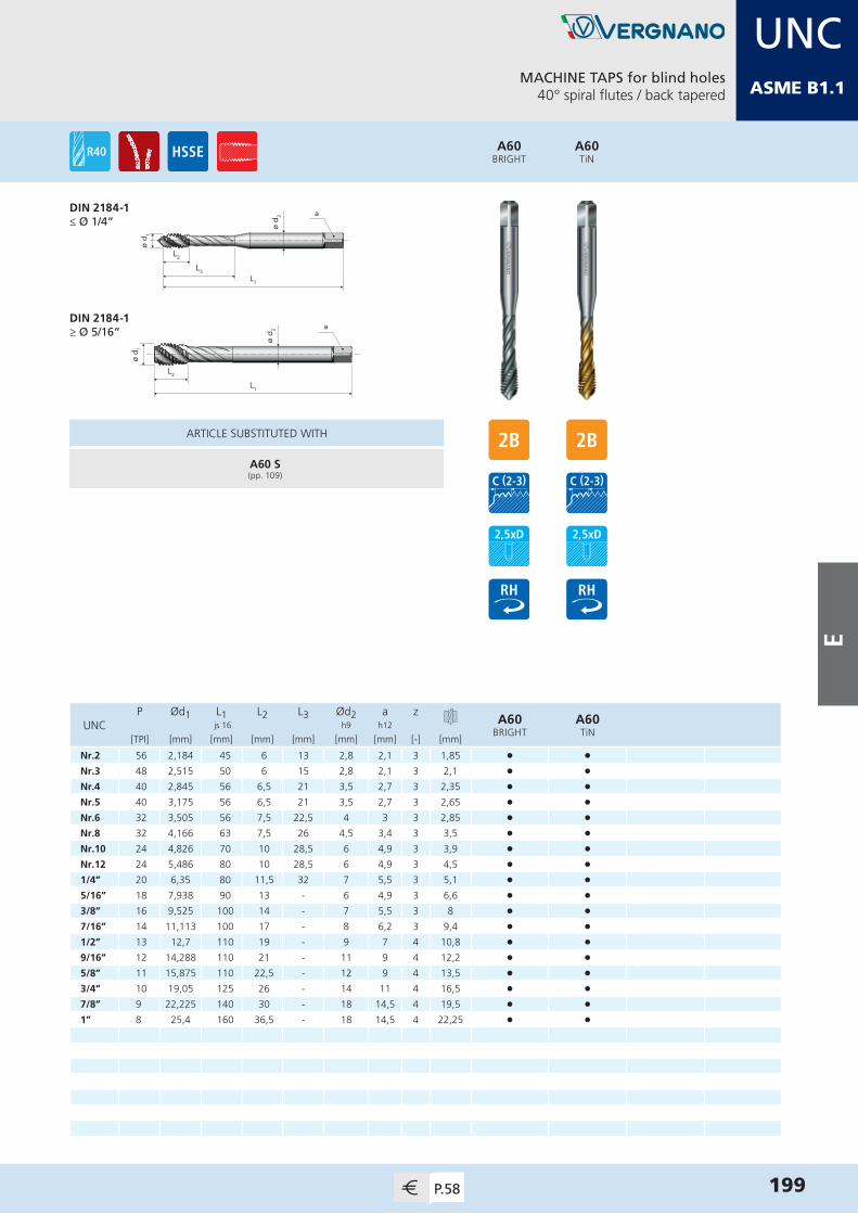
MACHINE TAPS for blind holes40° spiral flutes / back tapered
199P.58
UNCASME B1.1
A60BRIGHT
A60TiN
ø d 2
L1
L2
L3
ø d 1
a
ø d 1
L2
ø d 2 a
L1
DIN 2184-1≤ Ø 1/4”
DIN 2184-1≥ Ø 5/16”
P Ød1 L1 L2 L3 Ød2 a zA60
BRIGHTA60TiN
UNC js 16 h9 h12
[TPI] [mm] [mm] [mm] [mm] [mm] [mm] [-] [mm]
Nr.2 56 2,184 45 6 13 2,8 2,1 3 1,85 • •Nr.3 48 2,515 50 6 15 2,8 2,1 3 2,1 • •Nr.4 40 2,845 56 6,5 21 3,5 2,7 3 2,35 • •Nr.5 40 3,175 56 6,5 21 3,5 2,7 3 2,65 • •Nr.6 32 3,505 56 7,5 22,5 4 3 3 2,85 • •Nr.8 32 4,166 63 7,5 26 4,5 3,4 3 3,5 • •Nr.10 24 4,826 70 10 28,5 6 4,9 3 3,9 • •Nr.12 24 5,486 80 10 28,5 6 4,9 3 4,5 • •1/4” 20 6,35 80 11,5 32 7 5,5 3 5,1 • •5/16” 18 7,938 90 13 - 6 4,9 3 6,6 • •3/8” 16 9,525 100 14 - 7 5,5 3 8 • •7/16” 14 11,113 100 17 - 8 6,2 3 9,4 • • 1/2” 13 12,7 110 19 - 9 7 4 10,8 • •9/16” 12 14,288 110 21 - 11 9 4 12,2 • •5/8” 11 15,875 110 22,5 - 12 9 4 13,5 • •3/4” 10 19,05 125 26 - 14 11 4 16,5 • •7/8” 9 22,225 140 30 - 18 14,5 4 19,5 • •1” 8 25,4 160 36,5 - 18 14,5 4 22,25 • •
ARTICLE SUBSTITUTED WITH
A60 S(pp. 109)
E

MACHINE TAPS for blind holes40° spiral flutes / back tapered
200 P.59
UNFASME B1.1
A61BRIGHT
A61TiN
ø d 2
L1
L2
L3
ø d 1
a
ø d 1
L2
ø d 2 a
L1
DIN 2184-1≤ Ø 1/4”
DIN 2184-1≥ Ø 5/16”
P Ød1 L1 L2 L3 Ød2 a zA61
BRIGHTA61TiN
UNF js 16 h9 h12
[TPI] [mm] [mm] [mm] [mm] [mm] [mm] [-] [mm]
Nr.2 64 2,184 45 5,5 13 2,8 2,1 3 1,85 • •Nr.3 56 2,515 50 6 18 2,8 2,1 3 2,15 • •Nr.4 48 2,845 56 6 18 3,5 2,7 3 2,4 • •Nr.5 44 3,175 56 6 18 3,5 2,7 3 2,7 • •Nr.6 40 3,505 56 6,5 22 4 3 3 2,95 • •Nr.8 36 4,166 63 7 26,5 4,5 3,4 3 3,5 • •Nr.10 32 4,826 70 8 29 6 4,9 3 4,1 • •Nr.12 28 5,486 80 9 29,5 6 4,9 3 4,6 • •1/4” 28 6,35 80 10 32 7 5,5 3 5,5 • •5/16” 24 7,938 90 11 - 6 4,9 3 6,9 • •3/8” 24 9,525 90 12 - 7 5,5 3 8,5 • •7/16” 20 11,113 100 13,5 - 8 6,2 3 9,9 • • 1/2” 20 12,7 100 14,5 - 9 7 4 11,5 • •9/16” 18 14,288 100 15,5 - 11 9 4 12,9 • •5/8” 18 15,875 100 16 - 12 9 4 14,5 • •3/4” 16 19,05 110 18 - 14 11 4 17,5 • •7/8” 14 22,225 125 23,5 - 18 14,5 4 20,4 • •1” 12 25,4 140 26 - 18 14,5 4 23,25 • •
ARTICLE SUBSTITUTED WITH
A61 S(pp. 117)
E
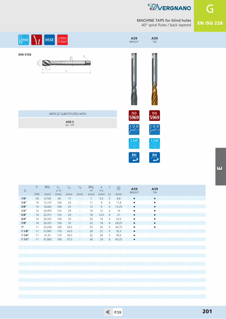
MACHINE TAPS for blind holes40° spiral flutes / back tapered
201P.59
GEN ISO 228
A59BRIGHT
A59TiN
ø d 1
L2ø
d 2 a
L1
DIN 5156
P Ød1 L1 L2 L3 Ød2 a zA59
BRIGHTA59TiN
G js 16 h9 h12
[TPI] [mm] [mm] [mm] [mm] [mm] [mm] [-] [mm]
1/8” 28 9,728 90 17 - 7 5,5 3 8,8 • •1/4” 19 13,157 100 23 - 11 9 4 11,8 • •3/8” 19 16,662 100 23 - 12 9 4 15,25 • •1/2” 14 20,955 125 29 - 16 12 4 19 • •5/8” 14 22,911 125 29 - 18 14,5 4 21 • •3/4” 14 26,441 140 29 - 20 16 4 24,5 • •7/8” 14 30,201 150 32 - 22 18 4 28,25 • •1” 11 33,249 160 34,5 - 25 20 4 30,75 • •1 1/8” 11 37,897 170 34,5 - 28 22 5 35,5 •1 1/4” 11 41,91 170 34,5 - 32 24 5 39,5 •1 1/2” 11 47,803 190 37,5 - 36 29 6 45,25 •
ARTICLE SUBSTITUTED WITH
A59 S(pp. 126)
E

FS E R I E S
Dies
F SE
RIE
S

MDIN 13
ø d2
h 1
ø d1
X200BRIGHT
DIESWith spiral point
DIN EN 22568
204 P.60
MDIN 13
APPLICATION RANGE - CUTTING SPEED m/min
ISO MG X200BRIGHT
X200 LHBRIGHT
PP.1-4 l l
P.7 l l
M M.1 l l
K K.2 l l
NN.1-3 l l
N.5-7 l l
X200 LHBRIGHT
Ød1 P Ød2 h1X200BRIGHT
X200 LHBRIGHT
[mm] [mm] [mm] [mm]
M 2 0,4 16 5 •2,2 0,45 16 5 •2,5 0,45 16 5 •3 0,5 20 5 • •3,5 0,6 20 5 •4 0,7 20 5 • •5 0,8 20 7 • •6 1 20 7 • •7 1 25 9 •8 1,25 25 9 • •9 1,25 25 9 •10 1,5 30 11 • •11 1,5 30 11 •12 1,75 38 14 • •14 2 38 14 • •16 2 45 18 •18 2,5 45 18 •20 2,5 45 18 •22 2,5 55 22 •24 3 55 22 •27 3 65 25 •30 3,5 65 25 •33 3,5 65 25 •36 4 65 25 •39 4 75 30 •
F SER
IES

MDIN 13
DIESWith spiral point
205P.61
MFDIN 13
ø d2
h 1
ø d1
X201BRIGHT
DIN EN 22568
APPLICATION RANGE - CUTTING SPEED m/min
ISO MG X201BRIGHT
PP.1-4 l
P.7 l
M M.1 l
K K.2 l
NN.1-3 l
N.5-7 l
Ød1 P Ød2 h1X201BRIGHT
[mm] [mm] [mm] [mm]
M 2 0,25 16 5 •2,2 0,25 16 5 •2,5 0,35 16 5 •3 0,35 20 5 •4 0,5 20 5 •5 0,5 20 5 •6 0,75 20 7 •7 0,75 25 9 •8 0,75 25 9 •8 1 25 9 •9 1 25 9 •10 0,75 30 11 • 10 1 30 11 •10 1,25 30 11 •11 1 30 11 •12 1 38 10 •12 1,25 38 10 •12 1,5 38 10 •14 1 38 10 •14 1,25 38 10 •14 1,5 38 10 •15 1 38 10 •15 1,5 38 10 •16 1 45 14 •16 1,5 45 14 •18 1 45 14 •
»
F SE
RIE
S
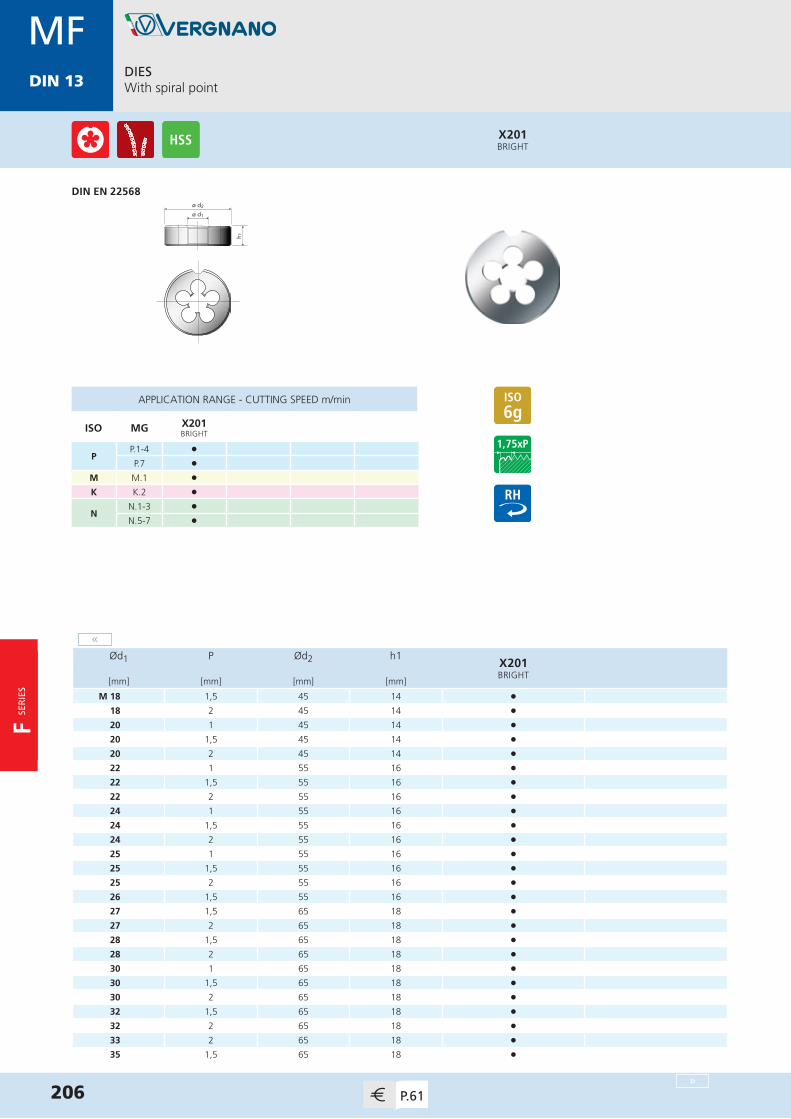
MDIN 13
ø d2
h 1
ø d1
X201BRIGHT
DIESWith spiral point
DIN EN 22568
206 P.61
MFDIN 13
APPLICATION RANGE - CUTTING SPEED m/min
ISO MG X201BRIGHT
PP.1-4 l
P.7 l
M M.1 l
K K.2 l
NN.1-3 l
N.5-7 l
Ød1 P Ød2 h1X201BRIGHT
[mm] [mm] [mm] [mm]
M 18 1,5 45 14 •18 2 45 14 •20 1 45 14 •20 1,5 45 14 •20 2 45 14 •22 1 55 16 •22 1,5 55 16 •22 2 55 16 •24 1 55 16 •24 1,5 55 16 •24 2 55 16 •25 1 55 16 •25 1,5 55 16 •25 2 55 16 •26 1,5 55 16 •27 1,5 65 18 •27 2 65 18 • 28 1,5 65 18 •28 2 65 18 •30 1 65 18 •30 1,5 65 18 •30 2 65 18 •32 1,5 65 18 •32 2 65 18 •33 2 65 18 •35 1,5 65 18 •
«
»
F SER
IES

MDIN 13
DIESWith spiral point
207P.61
MFDIN 13
ø d2
h 1
ø d1
X201BRIGHT
DIN EN 22568
APPLICATION RANGE - CUTTING SPEED m/min
ISO MG X201BRIGHT
PP.1-4 l
P.7 l
M M.1 l
K K.2 l
NN.1-3 l
N.5-7 l
Ød1 P Ød2 h1X201BRIGHT
[mm] [mm] [mm] [mm]
M 36 1,5 65 18 •36 2 65 18 •36 3 65 25 •
«
F SE
RIE
S
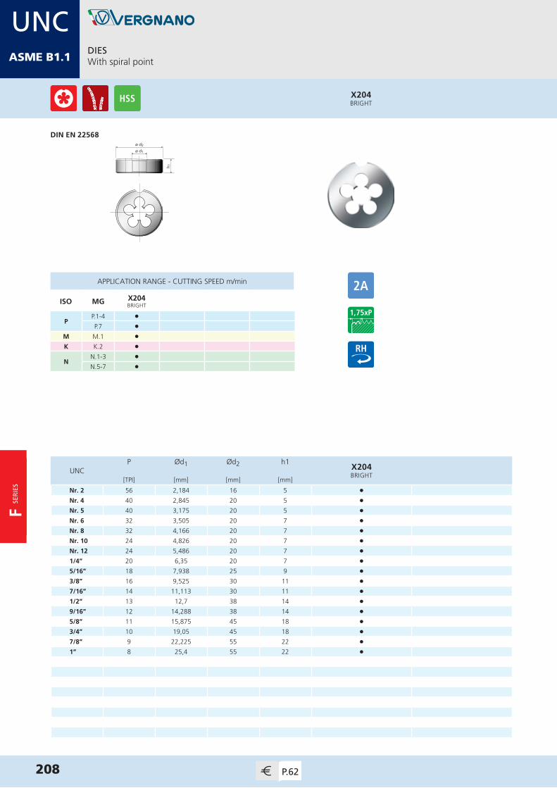
MDIN 13
ø d2
h 1
ø d1
X204BRIGHT
DIESWith spiral point
DIN EN 22568
208 P.62
UNCASME B1.1
APPLICATION RANGE - CUTTING SPEED m/min
ISO MG X204BRIGHT
PP.1-4 l
P.7 l
M M.1 l
K K.2 l
NN.1-3 l
N.5-7 l
P Ød1 Ød2 h1X204BRIGHT
UNC[TPI] [mm] [mm] [mm]
Nr. 2 56 2,184 16 5 •Nr. 4 40 2,845 20 5 •Nr. 5 40 3,175 20 5 •Nr. 6 32 3,505 20 7 •Nr. 8 32 4,166 20 7 •Nr. 10 24 4,826 20 7 •Nr. 12 24 5,486 20 7 •1/4” 20 6,35 20 7 •5/16” 18 7,938 25 9 •3/8” 16 9,525 30 11 •7/16” 14 11,113 30 11 •1/2” 13 12,7 38 14 • 9/16” 12 14,288 38 14 •5/8” 11 15,875 45 18 •3/4” 10 19,05 45 18 •7/8” 9 22,225 55 22 •1” 8 25,4 55 22 •
F SER
IES

MDIN 13
DIESWith spiral point
209P.62
UNFASME B1.1
ø d2
h 1
ø d1
X205BRIGHT
DIN EN 22568
APPLICATION RANGE - CUTTING SPEED m/min
ISO MG X205BRIGHT
PP.1-4 l
P.7 l
M M.1 l
K K.2 l
NN.1-3 l
N.5-7 l
P Ød1 Ød2 h1X205BRIGHT
UNF[TPI] [mm] [mm] [mm]
Nr. 3 56 2,515 16 5 •Nr. 4 48 2,845 20 5 •Nr. 5 44 3,175 20 5 •Nr. 6 40 3,505 20 5 •Nr. 8 36 4,166 20 7 •Nr. 10 32 4,826 20 7 •Nr. 12 28 5,486 20 7 •1/4” 28 6,35 20 7 •5/16” 24 7,938 25 9 •3/8” 24 9,525 30 11 •7/16” 20 11,113 30 11 •1/2” 20 12,7 38 10 • 9/16” 18 14,288 38 10 •5/8” 18 15,875 45 14 •3/4” 16 19,05 45 14 •7/8” 14 22,225 55 16 •1” 12 25,4 55 16 •
F SE
RIE
S

MDIN 13
ø d2
h 1
ø d1
X203BRIGHT
DIESWith spiral point
DIN EN 24231
210 P.63
GEN ISO 228
APPLICATION RANGE - CUTTING SPEED m/min
ISO MG X203BRIGHT
PP.1-4 l
P.7 l
M M.1 l
K K.2 l
NN.1-3 l
N.5-7 l
P Ød1 Ød2 h1X203BRIGHT
G[TPI] [mm] [mm] [mm]
1/8” 28 9,728 30 11 •1/4” 19 13,157 38 10 •3/8” 19 16,662 45 14 •1/2” 14 20,955 45 14 •5/8” 14 22,911 55 16 •3/4” 14 26,441 55 16 •7/8” 14 30,201 65 18 •1” 11 33,249 65 18 •1 1/4” 11 41,91 75 20 •1 1/2” 11 47,803 90 22 •2” 11 59,614 105 22 •
F SER
IES
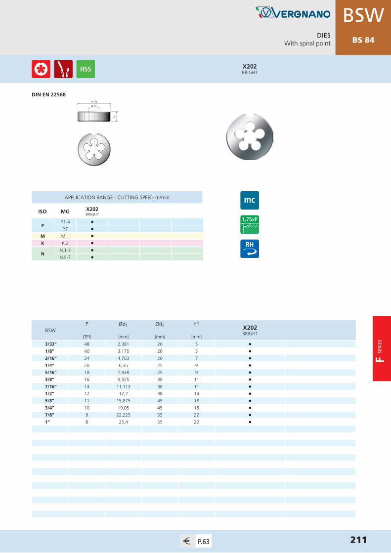
DIESWith spiral point
211P.63
BSWBS 84
ø d2
h 1
ø d1
X202BRIGHT
DIN EN 22568
APPLICATION RANGE - CUTTING SPEED m/min
ISO MG X202BRIGHT
PP.1-4 l
P.7 l
M M.1 l
K K.2 l
NN.1-3 l
N.5-7 l
P Ød1 Ød2 h1X202BRIGHT
BSW[TPI] [mm] [mm] [mm]
3/32” 48 2,381 20 5 •1/8” 40 3,175 20 5 •3/16” 24 4,763 20 7 •1/4” 20 6,35 25 9 •5/16” 18 7,938 25 9 •3/8” 16 9,525 30 11 •7/16” 14 11,113 30 11 •1/2” 12 12,7 38 14 •5/8” 11 15,875 45 18 •3/4” 10 19,05 45 18 •7/8” 9 22,225 55 22 •1” 8 25,4 55 22 •
F SE
RIE
S

ø d2
h 1
ø d1
X206BRIGHT
DIESWith spiral point
DIN EN 22568
212 P.63
NPTASME
B1.20.1
APPLICATION RANGE - CUTTING SPEED m/min
ISO MG X206BRIGHT
PP.1-4 l
P.7 l
M M.1 l
K K.2 l
NN.1-3 l
N.5-7 l
P Ød1 Ød2 h1X206BRIGHT
NPT[TPI] [mm] [mm] [mm]
1/16” 27 7,938 25 10 •1/8” 27 10,287 30 10 •1/4” 18 13,716 38 15 •3/8” 18 17,145 45 15,3 •1/2” 14 21,336 45 20 •3/4” 14 26,67 55 20,2 •1” 11,5 33,401 65 25 •
F SER
IES

VR SE
RIE
S
V RS E R I E S
Thread Mills

VR10 - VR20 - VR30
ISO 513 Material Group Application N/mm² Vc
m/minFeed (mm/tooth)
Ø2 Ø3 Ø4 Ø6 Ø8 Ø10 Ø12 Ø14 Ø16 Ø20
P Steel
P.1 Mild / magnetic steel 200 - 400 100-250 0,03 0,04 0,04 0,06 0,07 0,08 0,09 0,11 0,12 0,15
P.2 Construction steel,case hardening steel 350 - 700 100-250 0,03 0,04 0,04 0,06 0,07 0,08 0,09 0,11 0,12 0,15
P.3 Carbon steel 350 - 850 100-250 0,03 0,04 0,04 0,06 0,07 0,08 0,09 0,11 0,12 0,15
P.4 Alloyed steel, tempered steel 500 - 850 110-180 0,02 0,03 0,03 0,05 0,06 0,07 0,08 0,09 0,1 0,12
P.5 Alloyed steel, tempered steel 850 - 1200 90-160 0,02 0,02 0,03 0,03 0,04 0,05 0,05 0,06 0,07 0,08
P.6 Alloyed steel /high strength steel 1200 - 1600 90-140 0,02 0,02 0,02 0,02 0,03 0,04 0,04 0,05 0,06 0,07
P.7 Ferritic /martensitic stainless steel < 1000 110-180 0,02 0,03 0,03 0,05 0,06 0,07 0,08 0,09 0,1 0,12
M Stainlesssteel
M.1 Austenitic < 850 60-120 0,02 0,02 0,03 0,03 0,04 0,05 0,05 0,06 0,07 0,08
M.2 Ferritic-austenitic (Duplex) < 1000 50-100 0,02 0,02 0,03 0,03 0,04 0,05 0,05 0,06 0,07 0,08
K Cast iron
K.1 Grey cast iron < 1000 70-150 0,03 0,04 0,04 0,06 0,07 0,08 0,09 0,11 0,12 0,15
K.2 Nodular cast iron < 1000 100-250 0,03 0,04 0,04 0,06 0,07 0,08 0,09 0,11 0,12 0,15
K.3 Austempered ductile iron (ADI) < 1400 70-120 0,03 0,03 0,03 0,04 0,05 0,06 0,07 0,08 0,09 0,1
N
Aluminium alloys
N.1 Pure aluminium < 300 150-350 0,03 0,04 0,04 0,06 0,07 0,08 0,09 0,11 0,12 0,15
N.2 Aluminium alloys Si < 0,5% (long chipping) < 500 150-350 0,03 0,04 0,04 0,06 0,07 0,08 0,09 0,11 0,12 0,15
N.3 Aluminium alloys Si < 10% (medium chipping) < 500 150-350 0,03 0,04 0,04 0,06 0,07 0,08 0,09 0,11 0,12 0,15
N.4 Aluminium alloys Si > 10% (short chipping) < 600 100-250 0,02 0,02 0,03 0,03 0,04 0,05 0,05 0,06 0,07 0,08
Copperalloys
N.5 Pure copper 250 - 350 150-350 0,03 0,04 0,04 0,06 0,07 0,08 0,09 0,11 0,12 0,15
N.6 Copper alloys, Brass(long chipping) < 700 150-350 0,03 0,04 0,04 0,06 0,07 0,08 0,09 0,11 0,12 0,15
N.7 Copper alloys, Brass(short chipping) < 700 100-250 0,02 0,02 0,03 0,03 0,04 0,05 0,05 0,06 0,07 0,08
N.8 High strength bronze 700 - 1500 90-140 0,02 0,02 0,02 0,02 0,03 0,04 0,04 0,05 0,06 0,07
Magnesium alloys
N.9 Pure Magnesium /Magnesium alloys 120 - 300 150-350 0,03 0,04 0,04 0,06 0,07 0,08 0,09 0,11 0,12 0,15
N.10 High strength Magnesium alloys 240 - 400 150-350 0,03 0,04 0,04 0,06 0,07 0,08 0,09 0,11 0,12 0,15
S
Titanium alloys
S.1 Pure titanium 400 - 600 20-90 0,02 0,02 0,02 0,03 0,04 0,04 0,04 0,05 0,05 0,05
S.2 Titanium alloys 600 - 1000 20-80 0,02 0,02 0,02 0,03 0,03 0,03 0,03 0,04 0,04 0,04
Nickel alloys
S.3 Pure nickel 400 - 600 20-90 0,02 0,02 0,02 0,03 0,04 0,04 0,04 0,05 0,05 0,05
S.4 Nickel alloys 600 - 1000 20-80 0,02 0,02 0,02 0,03 0,03 0,03 0,03 0,04 0,04 0,04
214
VR SE
RIE
S
APPLICATION AND CUTTING SPEED TABLE
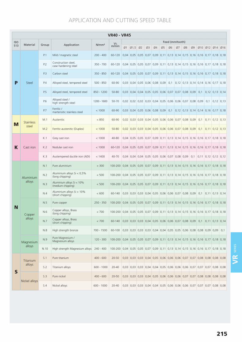
VR40 - VR45
ISO 513 Material Group Application N/mm² Vc
m/minFeed (mm/tooth)
Ø1 Ø1,5 Ø2 Ø3 Ø4 Ø5 Ø6 Ø7 Ø8 Ø9 Ø10 Ø12 Ø14 Ø16
P Steel
P.1 Mild / magnetic steel 200 - 400 60-120 0,04 0,05 0,05 0,07 0,09 0,11 0,13 0,14 0,15 0,16 0,16 0,17 0,18 0,18
P.2 Construction steel,case hardening steel 350 - 700 60-120 0,04 0,05 0,05 0,07 0,09 0,11 0,13 0,14 0,15 0,16 0,16 0,17 0,18 0,18
P.3 Carbon steel 350 - 850 60-120 0,04 0,05 0,05 0,07 0,09 0,11 0,13 0,14 0,15 0,16 0,16 0,17 0,18 0,18
P.4 Alloyed steel, tempered steel 500 - 850 60-90 0,03 0,04 0,05 0,06 0,08 0,09 0,1 0,12 0,13 0,14 0,14 0,16 0,17 0,18
P.5 Alloyed steel, tempered steel 850 - 1200 50-80 0,03 0,04 0,04 0,05 0,05 0,06 0,07 0,07 0,08 0,09 0,1 0,12 0,13 0,14
P.6 Alloyed steel /high strength steel 1200 - 1600 50-70 0,02 0,02 0,02 0,03 0,04 0,05 0,06 0,06 0,07 0,08 0,09 0,1 0,12 0,13
P.7 Ferritic /martensitic stainless steel < 1000 60-90 0,03 0,04 0,05 0,06 0,08 0,09 0,1 0,12 0,13 0,14 0,14 0,16 0,17 0,18
M Stainlesssteel
M.1 Austenitic < 850 60-90 0,02 0,03 0,03 0,04 0,05 0,06 0,06 0,07 0,08 0,09 0,1 0,11 0,12 0,13
M.2 Ferritic-austenitic (Duplex) < 1000 50-80 0,02 0,03 0,03 0,04 0,05 0,06 0,06 0,07 0,08 0,09 0,1 0,11 0,12 0,13
K Cast iron
K.1 Grey cast iron < 1000 40-80 0,04 0,05 0,05 0,07 0,09 0,11 0,13 0,14 0,15 0,16 0,16 0,17 0,18 0,18
K.2 Nodular cast iron < 1000 60-120 0,04 0,05 0,05 0,07 0,09 0,11 0,13 0,14 0,15 0,16 0,16 0,17 0,18 0,18
K.3 Austempered ductile iron (ADI) < 1400 40-70 0,04 0,04 0,04 0,05 0,05 0,06 0,07 0,08 0,09 0,1 0,11 0,12 0,12 0,12
N
Aluminium alloys
N.1 Pure aluminium < 300 100-200 0,04 0,05 0,05 0,07 0,09 0,11 0,13 0,14 0,15 0,16 0,16 0,17 0,18 0,18
N.2 Aluminium alloys Si < 0,5% (long chipping) < 500 100-200 0,04 0,05 0,05 0,07 0,09 0,11 0,13 0,14 0,15 0,16 0,16 0,17 0,18 0,18
N.3 Aluminium alloys Si < 10% (medium chipping) < 500 100-200 0,04 0,05 0,05 0,07 0,09 0,11 0,13 0,14 0,15 0,16 0,16 0,17 0,18 0,18
N.4 Aluminium alloys Si > 10% (short chipping) < 600 60-140 0,03 0,03 0,03 0,04 0,05 0,06 0,06 0,07 0,08 0,09 0,1 0,11 0,13 0,14
Copperalloys
N.5 Pure copper 250 - 350 100-200 0,04 0,05 0,05 0,07 0,09 0,11 0,13 0,14 0,15 0,16 0,16 0,17 0,18 0,18
N.6 Copper alloys, Brass(long chipping) < 700 100-200 0,04 0,05 0,05 0,07 0,09 0,11 0,13 0,14 0,15 0,16 0,16 0,17 0,18 0,18
N.7 Copper alloys, Brass(short chipping) < 700 60-140 0,03 0,03 0,03 0,04 0,05 0,06 0,06 0,07 0,08 0,09 0,1 0,11 0,13 0,14
N.8 High strength bronze 700 - 1500 60-100 0,03 0,03 0,03 0,03 0,04 0,04 0,05 0,05 0,06 0,08 0,08 0,09 0,09 0,1
Magnesium alloys
N.9 Pure Magnesium /Magnesium alloys 120 - 300 100-200 0,04 0,05 0,05 0,07 0,09 0,11 0,13 0,14 0,15 0,16 0,16 0,17 0,18 0,18
N.10 High strength Magnesium alloys 240 - 400 100-200 0,04 0,05 0,05 0,07 0,09 0,11 0,13 0,14 0,15 0,16 0,16 0,17 0,18 0,18
S
Titanium alloys
S.1 Pure titanium 400 - 600 20-50 0,03 0,03 0,03 0,04 0,05 0,06 0,06 0,06 0,07 0,07 0,08 0,08 0,08 0,08
S.2 Titanium alloys 600 - 1000 20-40 0,03 0,03 0,03 0,04 0,04 0,05 0,06 0,06 0,06 0,07 0,07 0,07 0,08 0,08
Nickel alloys
S.3 Pure nickel 400 - 600 20-50 0,03 0,03 0,03 0,04 0,05 0,06 0,06 0,06 0,07 0,07 0,08 0,08 0,08 0,08
S.4 Nickel alloys 600 - 1000 20-40 0,03 0,03 0,03 0,04 0,04 0,05 0,06 0,06 0,06 0,07 0,07 0,07 0,08 0,08
APPLICATION AND CUTTING SPEED TABLE
215
DIN 13
VR SE
RIE
S

VR50 - VR55
ISO 513 Material Group Application N/mm² Vc
m/minFeed (mm/tooth)
Ø1 Ø1,5 Ø2 Ø3 Ø4 Ø5 Ø6 Ø7 Ø8 Ø9 Ø10 Ø12 Ø14 Ø16
STitanium
alloys S.2 Titanium alloys 600 - 1000 20-40 0,03 0,03 0,03 0,04 0,04 0,05 0,06 0,06 0,06 0,07 0,07 0,07 0,08 0,08
Nickelalloys S.4 Nickel alloys 600 - 1000 20-40 0,03 0,03 0,03 0,04 0,04 0,05 0,06 0,06 0,06 0,07 0,07 0,07 0,08 0,08
H Hardened materials
H.1 Alloyed steel,hardness HRC 44-55 - 50-60 0,02 0,03 0,03 0,04 0,04 0,05 0,05 0,06 0,06 0,07 0,07 0,08 0,09 0,1
H.2 Alloyed steel,hardness HRC 56-62 - 40-50 0,01 0,02 0,02 0,03 0,03 0,04 0,05 0,05 0,06 0,06 0,06 0,07 0,08 0,09
216
APPLICATION AND CUTTING SPEED TABLE
PROCESS DESCRIPTION
VR SE
RIE
S
1 Start point - center position2 Axial movement down to required thread depth, then 45° arc entrance3 Thread milling (360°)4 45° arc exit, then axial movement to start point
1 Start point - center position2 45° arc entrance3 Thread milling to required thread depth4 45° arc exit5 Axial movement to start point
V R 1 0 - V R 2 0 - V R 3 0
1 2 3 4
V R 4 0 - V R 4 5 - V R 5 0 - V R 5 5
1 2 3 4 5
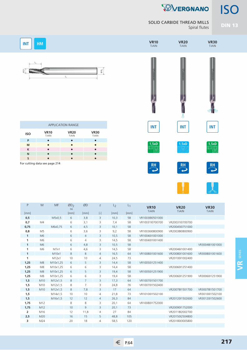
SOLID CARBIDE THREAD MILLSSpiral flutes
217P.64
L2
Ø D
L1
Ø D
2
P M MF ØD2 ØD z L2 L1 VR10TiAIN
VR20TiAIN
VR30TiAIN
h6
[mm] [mm] [mm] [-] [mm] [mm]
0,5 M5x0,5 6 3,8 3 10,3 58 VR10038I0501000
0,7 M4 6 3,1 3 7,4 58 VR10031I0700700 VR20031I0700700
0,75 M6x0,75 6 4,5 3 10,1 58 VR20045I0751000
0,8 M5 6 3,6 3 9,2 58 VR10036I0800900 VR20038I0800900
1 M6 6 4 3 10,5 58 VR10040I1001000
1 M6 6 4 3 14,5 58 VR10040I1001400
1 M6 6 4,8 3 10,5 58 VR30048I1001000
1 M6 M7x1 6 4,6 3 14,5 58 VR20046I1001400
1 M10x1 8 8 4 16,5 64 VR10080I1001600 VR20080I1001600 VR30080I1001600
1 M12x1 10 10 4 24,5 73 VR20100I1002400
1,25 M8 M10x1,25 6 5 3 14,4 58 VR10050I1251400
1,25 M8 M10x1,25 6 6 3 14,4 58 VR20060I1251400
1,25 M8 M10x1,25 6 5 3 19,4 58 VR10050I1251900
1,25 M8 M10x1,25 6 6 3 19,4 58 VR20060I1251900 VR30060I1251900
1,5 M10 M12x1,5 8 7 3 17,3 64 VR10070I1501700
1,5 M10 M12x1,5 8 7 3 24,8 76 VR10070I1502400
1,5 M10 M12x1,5 8 7,8 3 17 64 VR20078I1501700 VR30078I1501700
1,5 M14x1,5 10 10 4 21,8 73 VR10100I1502100 VR30100I1502100
1,5 M16x1,5 12 12 4 26,3 84 VR20120I1502600 VR30120I1502600
1,75 M12 8 8 3 20,1 64 VR10080I1752000
1,75 M12 10 9 3 20,1 73 VR20090I1752000
2 M16 12 11,8 4 27 84 VR20118I2002700
2,5 M20 16 15 5 48,8 105 VR20150I2504800
3 M24 20 18 4 58,5 120 VR20180I3005800
APPLICATION RANGE
ISO VR10TiAIN
VR20TiAIN
VR30TiAIN
P l l l
M l l l
K l l l
N l l l
S l l l
VR30TiAIN
VR20TiAIN
VR10TiAIN
ISODIN 13
For cutting data see page 214
VR SE
RIE
S

SOLID CARBIDE THREAD MILLSSpiral flutes
218 P.64
L2
Ø D
L1
Ø D
2
P M ØD2 ØD z L2 L1 VR40TiAIN
VR45TiAIN
h6
[mm] [mm] [mm] [-] [mm] [mm]
0,3 M1,4 3 1,05 3 4 39 VR45010I0300400
0,35 M1,6 3 1,2 3 4,8 39 VR45012I0350400
0,4 M2 6 1,53 3 4,5 58 VR40015I0400400
0,4 M2 3 1,53 3 6 39 VR45015I0400600
0,5 M3 6 2,37 3 6,5 58 VR40023I0500600
0,5 M3 6 2,37 3 9,5 58 VR45023I0500900
0,5 M3 6 2,37 3 9,5 105 VR45023I050090L
0,7 M4 6 3,1 3 9 58 VR40031I0700900
0,7 M4 6 3,1 3 12,5 58 VR45031I0701200
0,7 M4 6 3,1 3 12,5 105 VR45031I070120L
0,8 M5 6 3,8 3 12,5 58 VR40038I0801200
0,8 M5 6 3,8 3 16 58 VR45038I0801600
0,8 M5 6 3,8 3 16 105 VR45038I080160L
1 M6 6 4,65 3 14 58 VR40046I1001400
1 M6 6 4,65 3 20 58 VR45046I1002000
1 M6 6 4,65 3 20 105 VR45046I100200L
1,25 M8 6 5,95 3 18 58 VR40059I1251800
1,25 M8 6 6 3 24 58 VR45060I1252400
1,5 M10 8 7,8 3 23 64 VR40078I1502300
1,75 M12 10 9 3 26 73 VR40090I1752600
2 M16 12 11,8 4 35 84 VR40118I2003500
APPLICATION RANGE
ISO VR40TiAIN
VR45TiAIN
P l l
M l l
K l l
N l l
S l l
VR45TiAIN
VR40TiAIN
For cutting data see page 215
ISODIN 13
L2
Ø D
L1
Ø D
2
VR40
VR45
VR SE
RIE
S

SOLID CARBIDE THREAD MILLS for hardened materialsLefthand spiral flutes
219P.65
APPLICATION RANGE
ISO VR50TiAIN
VR55TiAIN
S l l
H l l
VR55TiAIN
VR50TiAIN
ISODIN 13
For cutting data see page 216
P M ØD2 ØD z L2 L1 VR50TiAIN
VR55TiAIN
h6
[mm] [mm] [mm] [-] [mm] [mm]
0,4 M2 6 1,53 3 4,5 58 VR50015I0400400
0,5 M3 6 2,37 3 6,5 58 VR50023I0500600
0,7 M4 6 3,1 3 9 58 VR50031I0700900
0,7 M4 6 3,1 3 12,5 58 VR55031I0701200
0,8 M5 6 3,8 3 12,5 58 VR50038I0801200
0,8 M5 6 3,8 3 16 58 VR55038I0801600
1 M6 6 4,65 3 14 58 VR50046I1001400
1 M6 6 4,65 3 20 58 VR55046I1002000
1,25 M8 6 6 3 18 58 VR50060I1251800
1,25 M8 6 6 3 24 58 VR55060I1252400
1,5 M10 8 7,8 3 23 64 VR50078I1502300
1,75 M12 10 9 3 26 73 VR50090I1752600
2 M16 12 11,8 4 35 84 VR50118I2003500
L2
Ø D
L1
Ø D
2
L2
Ø D
L1
Ø D
2
VR50
VR55
VR SE
RIE
S

220 P.65
L2
Ø D
L1
Ø D
2
P (TPI) UNC UNF ØD2 ØD z L2 L1 VR10TiAIN
VR20TiAIN
h6
[mm] [mm] [-] [mm] [mm]
28 1/4" 6 4 3 11,3 58 VR10040U28T1100
28 1/4" 6 5 3 11,3 58 VR20050U28T1100
24 5/16" 6 5 3 14,3 58 VR10050U24T1400
24 3/8" 8 7 3 20,6 64 VR10070U24T2000
24 5/16" 8 6,6 3 14,3 64 VR20066U24T1400
24 3/8" 8 8 4 20,6 64 VR20080U24T2000
20 1/4" 6 4,5 3 12,1 58 VR10045U20T1200
20 7/16"-1/2" 8 7 3 21 64 VR10070U20T2100
20 1/4" 6 4,7 3 12,1 58 VR20047U20T1200
20 7/16" 8 8 3 21 64 VR20080U20T2100
20 1/2" 10 10 4 22,3 73 VR20100U20T2200
18 5/16" 6 5 3 14,8 58 VR10050U18T1400
18 5/16" 6 5,6 3 14,8 58 VR20056U18T1400
16 3/8" 6 6 3 16,7 58 VR10060U16T1600
16 3/8" 8 6,7 3 16,7 64 VR20067U16T1600
14 7/16" 8 7 3 20,9 64 VR10070U14T2000
14 7/16" 8 7,7 3 20,9 64 VR20077U14T2000
13 1/2" 8 8 3 22,5 64 VR10080U13T2200
13 1/2" 10 9,2 3 22,5 73 VR20092U13T2200
11 5/8" 10 10 3 28,9 73 VR10100U11T2800
11 5/8" 12 11,4 3 28,9 84 VR20114U11T2800
APPLICATION RANGE
ISO VR10TiAIN
VR20TiAIN
P l l
M l l
K l l
N l l
S l l
VR20TiAIN
VR10TiAIN
For cutting data see page 214
SOLID CARBIDE THREAD MILLSSpiral flutes
UNASME B1.1
VR SE
RIE
S

SOLID CARBIDE THREAD MILLSSpiral flutes
221P.66
UNASME B1.1
L2
Ø D
L1
Ø D
2
APPLICATION RANGE
ISO VR40TiAIN
VR45TiAIN
P l l
M l l
K l l
N l l
S l l
VR45TiAIN
VR40TiAIN
For cutting data see page 215
L2
Ø D
L1
Ø D
2
VR40
VR45
P (TPI) UNC UNF ØD2 ØD z L2 L1 VR40TiAIN
VR45TiAIN
h6
[mm] [mm] [-] [mm] [mm]
28 1/4" 6 5 3 14,5 58 VR40050U28T1400
28 1/4" 6 5 3 19 58 VR45050U28T1900
24 5/16"-3/8" 8 6,6 3 17 64 VR40066U24T1700
24 5/16"-3/8" 8 6,6 3 24 64 VR45066U24T2400
20 1/4" 6 4,75 3 14 58 VR40047U20T1400
20 7/16" 8 8 3 25 64 VR40080U20T2500
20 1/4" 6 4,75 3 19 58 VR45047U20T1900
18 5/16" 6 6 3 17 58 VR40060U18T1700
18 5/8" 12 12 4 35 84 VR40120U18T3500
18 5/16" 6 6 3 23 58 VR45060U18T2300
16 3/8" 8 6,7 3 22 64 VR40067U16T2200
14 7/16" 8 7,7 3 25 64 VR40077U14T2500
13 1/2" 10 9,2 3 27,5 73 VR40092U13T2700
11 5/8" 12 11,4 3 34,5 84 VR40114U11T3400
VR SE
RIE
S

222 P.66
SOLID CARBIDE THREAD MILLS for hardened materialsLefthand spiral flutes
UNASME B1.1
APPLICATION RANGE
ISO VR50TiAIN
VR55TiAIN
S l l
H l l
VR55TiAIN
VR50TiAIN
For cutting data see page 216
L2
Ø D
L1
Ø D
2
L2
Ø D
L1
Ø D
2
VR50
VR55
P (TPI) UNC UNF ØD2 ØD z L2 L1 VR50TiAIN
VR55TiAIN
h6
[mm] [mm] [-] [mm] [mm]
28 1/4" 6 5 3 14,5 58 VR50050U28T1400
28 1/4" 6 5 3 19 58 VR55050U28T1900
24 5/16"-3/8" 8 6,6 3 17 64 VR50066U24T1700
24 5/16"-3/8" 8 6,6 3 24 64 VR55066U24T2400
20 1/4" 6 4,75 3 14 58 VR50047U20T1400
20 7/16" 8 8 3 25 64 VR50080U20T2500
20 1/4" 6 4,75 3 19 58 VR55047U20T1900
18 5/16" 6 6 3 17 58 VR50060U18T1700
18 5/8" 12 12 4 35 84 VR50012U18T3500
18 5/16" 6 6 3 23 58 VR55060U18T2300
16 3/8" 8 6,7 3 22 64 VR50067U16T2200
14 7/16" 8 7,7 3 25 64 VR50077U14T2500
13 1/2" 10 9,2 3 27,5 73 VR50092U13T2700
11 5/8" 12 11,4 3 34,5 84 VR50114U11T3400
VR SE
RIE
S

SOLID CARBIDE THREAD MILLSSpiral flutes
223P.66
GASEN ISO 228
L2
Ø D
L1
Ø D
2
APPLICATION RANGE
ISO VR10TiAIN
VR20TiAIN
P l l
M l l
K l l
N l l
S l l
VR20TiAIN
VR10TiAIN
For cutting data see page 214
P (TPI) G ØD2 ØD z L2 L1 VR10TiAIN
VR20TiAIN
[mm] [mm] [-] [mm] [mm]
28 1/16” - 1/8” 6 6 3 9,5 58 VR10060G28T0900
28 1/8" 8 7,8 3 14,1 64 VR20078G28T1400
19 1/4" - 3/8" 8 8 3 14 64 VR10080G19T1400
19 1/4" - 3/8" 10 10 4 16,7 73 VR20100G19T1600
14 1/2" - 7/8" 12 12 4 19 84 VR10120G14T1900
14 1/2" - 7/8" 16 16 5 26,3 105 VR20160G14T2600
11 1" - 1 1/2" 12 12 3 24,2 84 VR10120G11T2400
11 1" - 1 1/2" 16 16 4 38,1 105 VR20160G11T3800
VR SE
RIE
S

VA
SER
IES
VAS E R I E S
Synchronous Tapping Attachments

226
VA
SER
IES
Vergnano Sincro synchronous tapping attachments are specifically designed to enhance the performance of the Vergnano S-Series taps for synchronous tapping processes.
SYNCHRONOUS TAPPING ATTACHMENTS
In modern CNC machine tools with synchronous spindles, the rotational and axial movements of the spindle are coordinated by the numeric control of the machine. On these modern ma-chine tools standard compensated tapping attachments are not recommended since the large compensation in extension can negatively influence the performance of the tool. Vergnano Sincro synchronous tapping attachments are specifically designed for synchronous tapping: micro-compensation reduces the axial and radial forces generated during the tapping process and enhances tool life. Since machine, tapping attachment and tool are synchronised it is pos-sible to reach high machining speeds. This advantage, together with increased tool life, leads to improved productivity.
Quick-Change System
Vergnano offers a new system consisting in tapping attachmentand quick-change adaptor which allows worn tools to be substi-tuted without changing the entire tapping attachment thereby sa-ving precious machining time.It is recommended to have a second quick-change adaptor (in ad-dition to that delivered with the tapping attachment) sold separa-tely to exploit this advantage.
Also available are extended quick-change adaptors which permit extension of the tapping attachment in order to reach threads in difficult positions.
This versatile and cost-saving system covers a wide range of applications with just one tapping attachment.
The extended adapter is sold assembled and consists of two parts (adaptor and terminal adap-tor). Further extensions are available on request.
Terminal AdaptorExtension(on request)
Adaptor
TAPPING ATTACHMENTS

227
VA
SER
IES
Micro-Compensation
During tap reversal high axial forces are generated on the tap which cause mechanical stresses and micro-wear. This in turn leads to reduced tool life and tool precision. For this reason Ver-gnano synchronous tapping attachments are designed with differential micro-compensation in traction and compression which compensates the stresses on the tap.Compensation in traction (1 mm) is obtained by steel springs which guarantee greater reliabi-lity while compensation in compression (0,2 mm) is obtained by elastomer rings.
Through Coolant Capability
All Vergnano synchronous tapping attachments are designed for use with internal lubricationup to 50 bars. For higher values a special pressure-tight nut screw is available on request.The special attachment design forces the through coolant to enter the tap adaptor from the sides without interfering with the compensation length.
Elastomer ring for compensation in compression (0,2 mm)
Steel spring for compensation in traction (1,0 mm)

228 P.67
SYNCHRONOUS ER TAPPING ATTACHMENT with QUICK-CHANGE TAP ADAPTORWith internal through coolant capability (1)
Article Code Attachment Tap Size L ø D ø d ER collet L1 LTOT
[mm] [mm] [mm] [mm] [mm]
VA01A06302CH160 HSK-A63 M3 - M8 64 43 20 ER 16 20,5 84,5
VA01A06302CH250 HSK-A63 M6 - M20 97 60 32 ER 25 23,5 120,5
VA01A10002CH400 HSK-A100 M14 - M33 115 87 50 ER 40 28,5 143,5
SYNCHRONOUS ER TAPPING ATTACHMENT with QUICK-CHANGE TAP ADAPTORWith internal through coolant capability (1)
DIN 1835 B+E
Article Code Attachment Tap Size L ø D ø d ER collet L1 LTOT
ø D1 [mm] [mm] [mm] [mm] [mm] [mm]
VA01C02502CH160 25 M3 - M8 34 43 20 ER 16 20,5 54,5
VA01C02502CH250 25 M6 - M20 56 60 32 ER 25 23,5 79,5
VA01C04002CH400 40 M14 - M33 80 87 50 ER 40 28,5 108,5
VA
SER
IES
DIN 69893 HSK A
DD 1 d
L TOT
L L1
Dd
LTOT
L L1
(1) For coolant pressure above 50 bars a special nut screw is available on request

SYNCHRONOUS ER TAPPING ATTACHMENT with QUICK-CHANGE TAP ADAPTORWith internal through coolant capability (1)
229P.67
Article Code Attachment Tap Size L ø D ø d ER collet L1 LTOT
[mm] [mm] [mm] [mm] [mm]
VA01B04002CH160 SK 40 AD M3 - M8 53 43 20 ER 16 20,5 73,5
VA01B05002CH160 SK 50 AD M3 - M8 53 43 20 ER 16 20,5 73,5
VA01B04002CH250 SK 40 AD M6 - M20 90 60 32 ER 25 23,5 113,5
VA01B05002CH250 SK 50 AD M6 - M20 74 60 32 ER 25 23,5 97,5
SYNCHRONOUS ER TAPPING ATTACHMENT with QUICK-CHANGE TAP ADAPTORWith internal through coolant capability (1)
SK DIN 69871 AD+B
Article Code Attachment Tap Size L ø D ø d ER collet L1 LTOT
[mm] [mm] [mm] [mm] [mm]
VA01B05002CH400 SK 50 B M14 - M33 115 87 50 ER 40 28,5 143,5
SK DIN 69871 AD
VA
SER
IES
DdL TOT
L L1
Dd
L TOT
L L1
(1) For coolant pressure above 50 bars a special nut screw is available on request

VA
SER
IES
230 P.67
SYNCHRONOUS ER TAPPING ATTACHMENT with QUICK-CHANGE TAP ADAPTORWith internal through coolant capability (1)
SYNCHRONOUS ER TAPPING ATTACHMENT with QUICK-CHANGE TAP ADAPTORWith internal through coolant capability (1)
Article Code Attachment Tap Size L ø D ø d ER collet L1 LTOT
[mm] [mm] [mm] [mm] [mm]
VA01M04002CH160 BT 40 M3 - M8 61 43 20 ER 16 20,5 81,5
VA01M05002CH160 BT 50 M3 - M8 72 43 20 ER 16 20,5 92,5
VA01M04002CH250 BT 40 M6 - M20 82 60 32 ER 25 23,5 105,5
VA01M05002CH250 BT 50 M6 - M20 93 60 32 ER 25 23,5 116,5
MAS 403 BT - B
Article Code Attachment Tap Size L ø D ø d ER collet L1 LTOT
[mm] [mm] [mm] [mm] [mm]
VA01M05002CH400 BT 50 B M14 - M33 124 87 50 ER 40 28,5 152,5
MAS 403 BT
(1) For coolant pressure above 50 bars a special nut screw is available on request
Dd
L TOT
L L1
DdL TOT
L L1
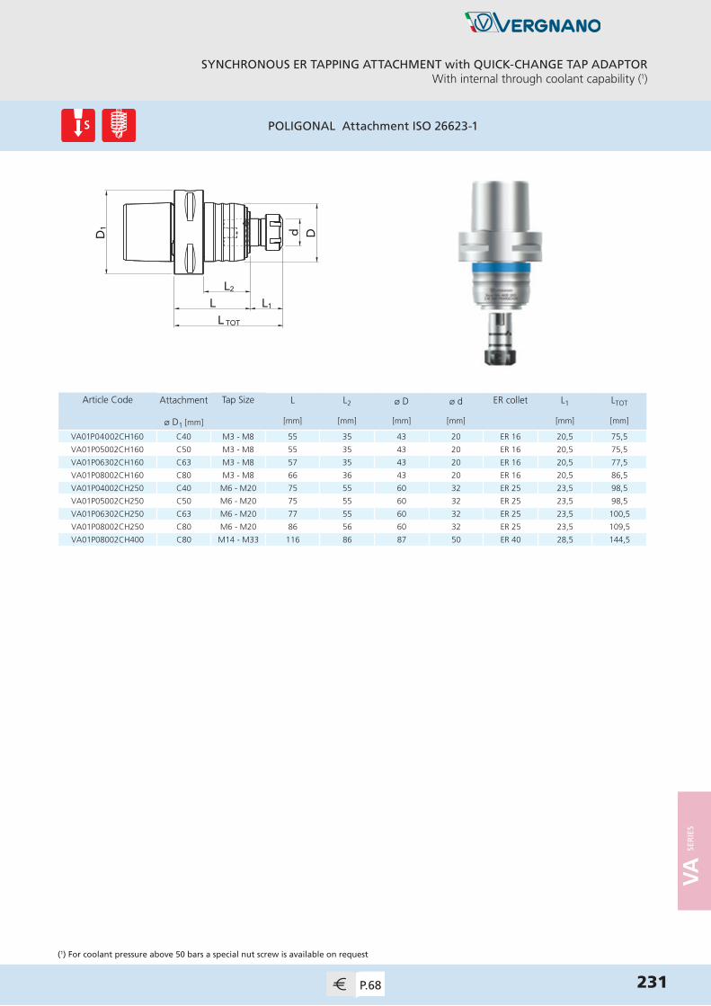
VA
SER
IES
SYNCHRONOUS ER TAPPING ATTACHMENT with QUICK-CHANGE TAP ADAPTORWith internal through coolant capability (1)
231P.68
POLIGONAL Attachment ISO 26623-1
(1) For coolant pressure above 50 bars a special nut screw is available on request
Article Code Attachment Tap Size L L2 ø D ø d ER collet L1 LTOT
ø D1 [mm] [mm] [mm] [mm] [mm] [mm] [mm]
VA01P04002CH160 C40 M3 - M8 55 35 43 20 ER 16 20,5 75,5
VA01P05002CH160 C50 M3 - M8 55 35 43 20 ER 16 20,5 75,5
VA01P06302CH160 C63 M3 - M8 57 35 43 20 ER 16 20,5 77,5
VA01P08002CH160 C80 M3 - M8 66 36 43 20 ER 16 20,5 86,5
VA01P04002CH250 C40 M6 - M20 75 55 60 32 ER 25 23,5 98,5
VA01P05002CH250 C50 M6 - M20 75 55 60 32 ER 25 23,5 98,5
VA01P06302CH250 C63 M6 - M20 77 55 60 32 ER 25 23,5 100,5
VA01P08002CH250 C80 M6 - M20 86 56 60 32 ER 25 23,5 109,5
VA01P08002CH400 C80 M14 - M33 116 86 87 50 ER 40 28,5 144,5
DD 1 d
L TOT
L L1
L2
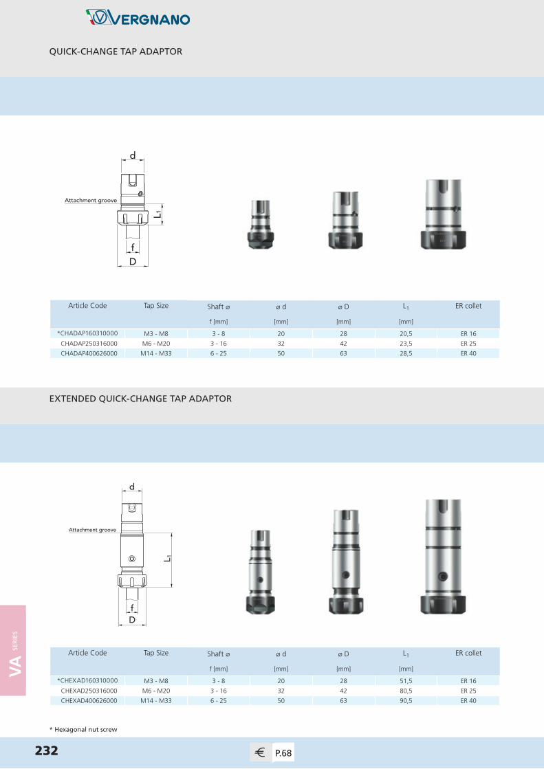
VA
SER
IES
232 P.68
QUICK-CHANGE TAP ADAPTOR
EXTENDED QUICK-CHANGE TAP ADAPTOR
Article Code Tap Size Shaft ø ø d ø D L1 ER collet
f [mm] [mm] [mm] [mm]
*CHADAP160310000 M3 - M8 3 - 8 20 28 20,5 ER 16
CHADAP250316000 M6 - M20 3 - 16 32 42 23,5 ER 25
CHADAP400626000 M14 - M33 6 - 25 50 63 28,5 ER 40
* Hexagonal nut screw
Df
d
Attachment groove
L1
Df
d
Attachment groove
L 1
Article Code Tap Size Shaft ø ø d ø D L1 ER collet
f [mm] [mm] [mm] [mm]
*CHEXAD160310000 M3 - M8 3 - 8 20 28 51,5 ER 16
CHEXAD250316000 M6 - M20 3 - 16 32 42 80,5 ER 25
CHEXAD400626000 M14 - M33 6 - 25 50 63 90,5 ER 40

VA
SER
IES
ER COLLET (sealed)with internal square
233P.69
DIN 6499
a8°
d1
L 2L 2 L 3
Article Code ER collet ø d1 a L2 L3
[mm] [mm] [mm] [mm]
SLERGB160103500 ER 16 3,5 2,7 18 24
SLERGB160104500 ER 16 4,5 3,4 18 24
SLERGB160105500 ER 16 5,5 4,3 18 25
SLERGB160106000 ER 16 6 4,9 18 26
SLERGB160107000 ER 16 7 5,5 18 26
SLERGB160108000 ER 16 8 6,2 22 31
SLERGB250103500 ER 25 3,5 2,7 18 24
SLERGB250104500 ER 25 4,5 3,4 18 24
SLERGB250105500 ER 25 5,5 4,3 18 25
SLERGB250106000 ER 25 6 4,9 18 26
SLERGB250107000 ER 25 7 5,5 18 26
SLERGB250108000 ER 25 8 6,2 22 31
SLERGB250109000 ER 25 9 7 22 32
SLERGB250110000 ER 25 10 8 25 36
SLERGB250111000 ER 25 11 9 25 37
SLERGB250112000 ER 25 12 9 25 37
SLERGB250114000 ER 25 14 11 25 39
SLERGB250116000 ER 25 16 12 25 40
SLERGB400106000 ER 40 6 4,9 18 26
SLERGB400107000 ER 40 7 5,5 18 26
SLERGB400108000 ER 40 8 6,2 22 31
SLERGB400109000 ER 40 9 7 22 32
SLERGB400110000 ER 40 10 8 25 36
SLERGB400111000 ER 40 11 9 25 37
SLERGB400112000 ER 40 12 9 25 37
SLERGB400114000 ER 40 14 11 25 39
SLERGB400116000 ER 40 16 12 25 40
SLERGB400118000 ER 40 18 14,5 25 42
SLERGB400120000 ER 40 20 16 28 47
SLERGB400122000 ER 40 22 18 28 49
SLERGB400125000 ER 40 25 20 33 56

VA
SER
IES
234 P.69
ASSEMBLY SUPPORT
WRENCH for nut screw
Article Code ER collet ø d
[mm]
ASCHADAP1620000 ER 16 20
ASCHADAP2532000 ER 25 32
ASCHADAP4050000 ER 40 50
Article Code Nut Screw ER collet
KE02ER160200000 Hexagonal ER 16
KE04ER250200000 Standard ER 25
KE04ER400200000 Standard ER 40
d

VA
SER
IES
TAPPING ATTACHMENTS: TERMINOLOGY AND ASSEMBLY INSTRUCTIONS
TIGHTENING TORQUE TABLE
1 Place the quick-change adaptor in the assembly support2 Insert the ER collet in the nut screw3 Partially tighten the nut screw on the quick-change adaptor4 Insert the tap in the quick-change adaptor until it stops5 Securely tighten the nut screw with a wrench6 Insert the quick-change adaptor into the tapping attachment by pulling back the sleeve
Synchronous Tap
Nut Screw for ER collet
ER collet (sealed)
Quick-Change Adaptor
Assembly Support
Tapping Attachment Quick-ChangeAdaptor
Tap
ER Collet Torque [Nm]
ER 16 45
ER 25 70
ER 40 150
It is recommended to tighten the nut screws with the torque values shown in the table below.
235

T E C H N I C A L I N F O R M AT I O N
ii IN
FO

TA P T E R M I N O L O G Y
238
ø d 2
L1
L2
LL3
a
L4
ø d 1
Cm
ø d 4
Cf
ø d 1
L1
L2ø
d 2
L5
a
L
d1 Nominal diameterthe diameter used for the purpose of
general identification.
dmPitch diameterthe diameter measured where the width
of the thread is equal to half the pitch.
d2Shank diameter the diameter of the shank, important
for the tapping attachment.
d3Chamfer diameterthe diameter at the leading endof the chamfer.
d4Neck diameterthe diameter of the reduced section
between the thread and shank of the tap.
d5Core diameterthe diameter of a circle tangent to the
bottom of the flutes.
IChamferthe taper on the threads at the front
end of the tap made by grinding and
relieving the crests of the first few teeth.
aSquarethe square with rounded corners formed by four flats parallel to the tap axis. The square serves to drive the tap.
A
A - A
AI S
B - B
B
B
i INFO
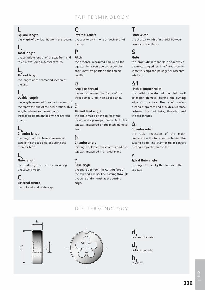
TA P T E R M I N O L O G Y
D I E T E R M I N O L O G Y
239
LSquare lengththe length of the flats that form the square.
L1Total lengththe complete length of the tap from end
to end, excluding external centres.
L2Thread lengththe length of the threaded section of
the tap.
L3Usable lengththe length measured from the front end of
the tap to the end of the neck section. This
length determines the maximum
threadable depth on taps with reinforced
shank.
L4Chamfer lengththe length of the chamfer measured
parallel to the tap axis, excluding the
chamfer bevel.
L5Flute lengththe axial length of the flute including
the cutter sweep.
CmExternal centrethe pointed end of the tap.
CfInternal centrethe countersink in one or both ends of
the tap.
PPitchthe distance, measured parallel to the
tap axis, between two corresponding
and successive points on the thread
profile.
αAngle of threadthe angle between the flanks of the
thread (measured in an axial plane).
δThread lead angle the angle made by the spiral of the
thread and a plane perpendicular to the
tap axis, measured on the pitch diameter
line.
βChamfer anglethe angle between the chamfer and the
tap axis, measured in an axial plane.
γRake anglethe angle between the cutting face of
the tap and a radial line passing through
the crest of the tooth at the cutting
edge.
TLand widththe chordal width of material between
two successive flutes.
SFlutethe longitudinal channels in a tap which
create cutting edges. The flutes provide
space for chips and passage for coolant/
lubricant.
Δ1Pitch diameter reliefthe radial reduction of the pitch and/
or major diameter behind the cutting
edge of the tap. The relief confers
cutting properties and provides clearance
between the part being threaded and
the tap threads.
ΔChamfer reliefthe radial reduction of the major
diameter on the tap chamfer behind the
cutting edge. The chamfer relief confers
cutting properties to the tap.
εSpiral flute anglethe angle formed by the flutes and the
tap axis.
ø d 2
h1
ø d 1
d1nominal diameter
d2outside diameter
h1thickness
i INFO
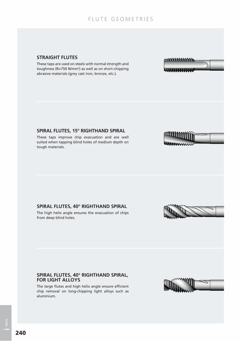
F L U T E G E O M E T R I E S
240
STRAIGHT FLUTESThese taps are used on steels with normal strength and toughness (R=750 N/mm2) as well as on short-chipping abrasive materials (grey cast iron, bronze, etc.).
SPIRAL FLUTES, 15° RIGHTHAND SPIRALThese taps improve chip evacuation and are well suited when tapping blind holes of medium depth on tough materials.
SPIRAL FLUTES, 40° RIGHTHAND SPIRALThe high helix angle ensures the evacuation of chips from deep blind holes.
SPIRAL FLUTES, 40° RIGHTHAND SPIRAL, FOR LIGHT ALLOYSThe large flutes and high helix angle ensure efficient chip removal on long-chipping light alloys such as aluminium.
i INFO

F L U T E G E O M E T R I E S
241
STRAIGHT FLUTES WITH INTERRUPTED THREADSFor tapping soft and mild materials such as iron, aluminium etc. The interrupted threads avoid chips sticking to the thread flanks and consequent damage of the tap.
SPIRAL POINTThe spiral point or gun nose is produced by a high helix angle combined with an increased rake angle in the front area of the tap. This design ensures spontaneous chip evacuation in the feed direction.This geometry is suitable when tapping through holes on materials which produce continuous chips.
FORMING TAPS WITHOUT OIL GROOVESThese tools produce threads through plastic deformation of the workpiece material. No chips are produced during the tapping process.
FORMING TAPS WITH OIL GROOVESThe oil grooves improve lubrication in the chamfer area making these taps suitable for threading deep holes.
i INFO
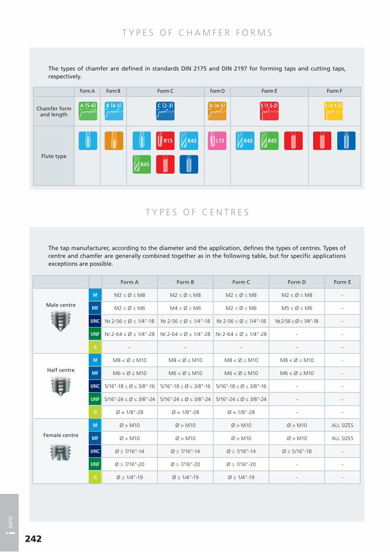
T Y P E S O F C H A M F E R F O R M S
T Y P E S O F C E N T R E S
242
Form A Form B Form C Form D Form E Form F
Chamfer formand length
Flute type
Form A Form B Form C Form D Form E
Male centre
M2 ≤ Ø ≤ M8 M2 ≤ Ø ≤ M8 M2 ≤ Ø ≤ M8 M2 ≤ Ø ≤ M8 -
M2 ≤ Ø ≤ M6 M4 ≤ Ø ≤ M6 M2 ≤ Ø ≤ M6 M5 ≤ Ø ≤ M6 -
Nr.2-56 ≤ Ø ≤ 1/4"-18 Nr.2-56 ≤ Ø ≤ 1/4"-18 Nr.2-56 ≤ Ø ≤ 1/4"-18 Nr.2-56 ≤ Ø ≤ 1/4"-18 -
Nr.2-64 ≤ Ø ≤ 1/4"-28 Nr.2-64 ≤ Ø ≤ 1/4"-28 Nr.2-64 ≤ Ø ≤ 1/4"-28 - -
- - - - -
Half centre
M8 < Ø ≤ M10 M8 < Ø ≤ M10 M8 < Ø ≤ M10 M8 < Ø ≤ M10 -
M6 < Ø ≤ M10 M6 < Ø ≤ M10 M6 < Ø ≤ M10 M6 < Ø ≤ M10 -
5/16"-18 ≤ Ø ≤ 3/8"-16 5/16"-18 ≤ Ø ≤ 3/8"-16 5/16"-18 ≤ Ø ≤ 3/8"-16 - -
5/16"-24 ≤ Ø ≤ 3/8"-24 5/16"-24 ≤ Ø ≤ 3/8"-24 5/16"-24 ≤ Ø ≤ 3/8"-24 - -
Ø = 1/8"-28 Ø = 1/8"-28 Ø = 1/8"-28 - -
Female centre
Ø > M10 Ø > M10 Ø > M10 Ø > M10 ALL SIZES
Ø > M10 Ø > M10 Ø > M10 Ø > M10 ALL SIZES
Ø ≥ 7/16"-14 Ø ≥ 7/16"-14 Ø ≥ 7/16"-14 Ø ≥ 5/16"-18 -
Ø ≥ 7/16"-20 Ø ≥ 7/16"-20 Ø ≥ 7/16"-20 - -
Ø ≥ 1/4"-19 Ø ≥ 1/4"-19 Ø ≥ 1/4"-19 - -
The types of chamfer are defined in standards DIN 2175 and DIN 2197 for forming taps and cutting taps, respectively.
The tap manufacturer, according to the diameter and the application, defines the types of centres. Types of centre and chamfer are generally combined together as in the following table, but for specific applications exceptions are possible.
i INFO

F O R M U L A E
CO N V E R S I O N TA B L E H A R D N E S S V S T E N S I L E S T R E N G T H
243
TensileStrength Hardness
R[N/mm2]
HBBrinell
HRCRockwell C
HVVickers
3400 700 68 10083120 688 67 9552960 676 66 9202890 670 65 8852770 659 64 8502240 650 63 8262190 635 62 7972140 627 61 7722100 613 60 7462050 600 59 7202010 587 58 6931970 574 57 6661930 561 56 6461890 548 55 6231850 536 54 6041810 524 53 5851780 512 52 5671730 500 51 5491680 488 50 5281630 476 49 5131590 464 48 4971560 453 47 4821520 442 46 4681480 430 45 4531440 419 44 440
TensileStrength Hardness
R[N/mm2]
HBBrinell
HRCRockwell C
HVVickers
1400 408 43 4271360 398 42 4161320 389 41 4041300 377 40 3911260 367 39 3811230 357 38 3711190 347 37 3571150 337 36 3451120 327 35 3321100 319 34 3231060 309 33 3141040 301 32 3041010 294 31 296980 286 30 288960 279 29 280940 272 28 273910 265 27 266890 259 26 259870 253 25 253850 247 24 247830 241 23 241810 235 22 235790 230 21 230770 225 20 225
(*) The torque value is valid for a new cutting tap.
For worn-out taps, the value can increase up to 2-3 times.
For forming taps, the value must be multiplied by 1,5-2
times.
M.G. Kc[N/mm2]
P.1 1300
P.2 1400
P.3 1400
P.4 1600
P.5 1700
P.6 2000
P.7 1400
M.1 1600
M.2 1800
K.1 1100
K.2 1500
K.3 1600
N.1 600
N.2 800
N.3 900
N.4 1000
N.5 700
N.6 850
N.7 900
N.8 2500
N.9 400
N.10 500
S.1 1200
S.2 1900
S.3 1300
S.4 2400
Parameter Formula Unit ofMeasurement
Cutting speedm____
min
Rotational speed rpm
Torque (*) N · m
Spindle power W
Nominal diameter d1 mm
Feed p · Nmm____min
p Thread pitch mm
z Number of flutes -
Kc
Cutting force coefficient (function of the material
and of tap wear)
N____mm2
N · p · d1
1000Vc =
1000 · Vc
p · d1
N =
Kc · p2 · z0,6 · d1
104Mt =
Mt · 2 · p · N
60P =
i INFO
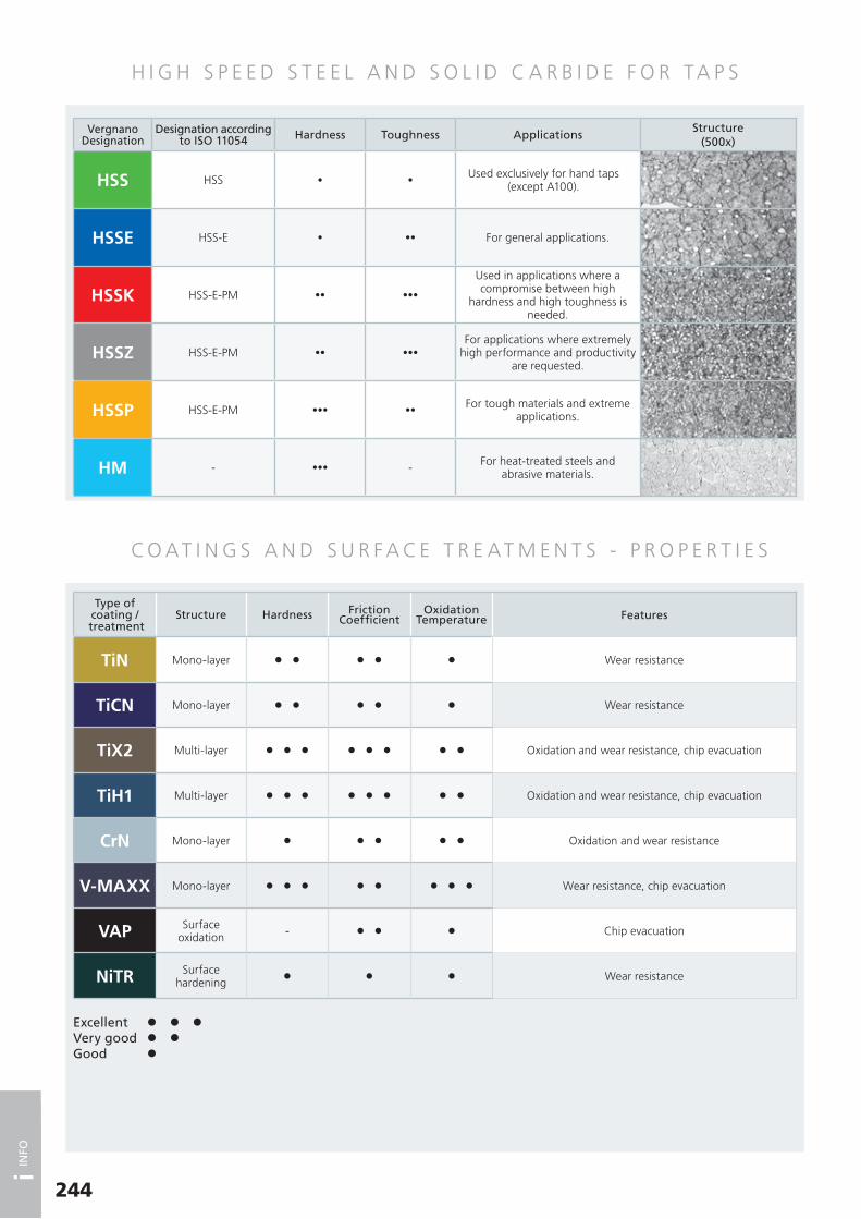
H I G H S P E E D S T E E L A N D S O L I D C A R B I D E F O R TA P S
CO AT I N G S A N D S U R F A C E T R E AT M E N T S - P R O P E R T I E S
244
Excellent l l lVery good l lGood l
Type of coating /
treatmentStructure Hardness Friction
CoefficientOxidation
Temperature Features
TiN Mono-layer l l l l l Wear resistance
TiCN Mono-layer l l l l l Wear resistance
TiX2 Multi-layer l l l l l l l l Oxidation and wear resistance, chip evacuation
TiH1 Multi-layer l l l l l l l l Oxidation and wear resistance, chip evacuation
CrN Mono-layer l l l l l Oxidation and wear resistance
V-MAXX Mono-layer l l l l l l l l Wear resistance, chip evacuation
VAP Surface oxidation - l l l Chip evacuation
NiTR Surface hardening
l l l Wear resistance
VergnanoDesignation
Designation accordingto ISO 11054 Hardness Toughness Applications
Structure(500x)
HSS HSS • •Used exclusively for hand taps
(except A100).
HSSE HSS-E • •• For general applications.
HSSK HSS-E-PM •• •••
Used in applications where a compromise between high
hardness and high toughness is needed.
HSSZ HSS-E-PM •• •••For applications where extremely
high performance and productivity are requested.
HSSP HSS-E-PM ••• ••For tough materials and extreme
applications.
HM - ••• - For heat-treated steels andabrasive materials.
i INFO

CO AT I N G S - A P P L I C AT I O N S F O R C U T T I N G S TA P S
CO AT I N G S - A P P L I C AT I O N S F O R CO L D F O R M I N G TA P S
245
COATINGS RECOMMENDED FOR CUTTINGS TAPS TiN TiCN TiX2 TiH1 CrN V-MAXX VAP NiTR
ISO Material Group Application Coating
P Steel
P.1 Mild / magnetic steel m m l
P.2 Construction steel, case hardening steel l m m
P.3 Carbon steel l m
P.4 Alloyed steel / tempered steel m m l
P.5 Alloyed steel / tempered steel m m l
P.6 Alloyed steel / high strength steel m m l
P.7Ferritic stainless steel, martensitic stainless steel, precipitation hardening
m l m
M StainlessSteel
M.1 Austenitic stainless steel l m m
M.2 Ferritic+austenitic (Duplex) l m m
K Cast iron
K.1 Grey cast iron m l m
K.2 Nodular cast iron, malleable cast iron, tempered cast iron l m
K.3 Austempered ductile iron (ADI) l
N
AluminiumAluminium alloys
N.1 Pure aluminium l m
N.2Aluminium wrought and die cast alloys with Si < 0,5% (long chipping)
m l m
N.3Aluminium wrought and die cast alloys with Si > 10% (medium chipping)
m l m
N.4 Aluminium die cast alloys with Si > 10% (short chipping) m l m
CopperCopper alloysBrass Bronze
N.5 Pure copper l m
N.6 Copper alloys (long chipping), soft brass m l m
N.7 Copper alloys (short chipping), hard brass l m
N.8 High strength bronze m l mMagnesiumMagnesiumalloys
N.9 Pure magnesium, magnesium alloys m l
N.10 High strength magnesium alloys m l
S
TitaniumTitaniumalloys
S.1 Pure titanium m l
S.2 Titanium alloys m l
Nickel Nickel alloys
S.3 Pure nickel m l
S.4 Nickel alloys m l
H Hardened materials
H.1 Alloyed steel, hardness HRC 44-55 m
H.2 Alloyed steel, hardness HRC 56-63 m
COATINGS RECOMMENDED FOR COLD FORMING TAPS TiN TiCN V-MAXX VAPISO Material Group Application Coating
P Steel
P.1 Mild / magnetic steel m l
P.2 Construction steel, case hardening steel l m
P.3 Carbon steel l m m
P.4 Alloyed steel / tempered steel l m l
P.5 Alloyed steel / tempered steel l m l
P.7 Ferritic stainless steel, martensitic stainless steel, precipitation hardening m l
M StainlessSteel
M.1 Austenitic stainless steel m l
M.2 Ferritic+austenitic (Duplex) m l
N
AluminiumAluminium alloys
N.1 Pure aluminium m l
N.2 Aluminium wrought and die cast alloys with Si < 0,5% (long chipping) l m m m
N.3 Aluminium wrought and die cast alloys with Si < 10 % (medium chipping) l m m m
CopperCopper alloysBrass/Bronze
N.5 Pure copper m l
N.6 Copper alloys (long chipping), soft brass l m m
S
TitaniumTitaniumalloys
S.1 Pure titanium l
S.2 Titanium alloys l
Nickel Nickel alloys
S.3 Pure nickel m l
S.4 Nickel alloys m l
l Idealm Suitable
i INFO
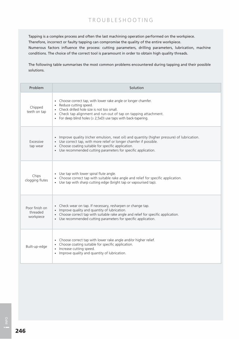
T R O U B L E S H O O T I N G
Problem Solution
Chipped teeth on tap
• Choose correct tap, with lower rake angle or longer chamfer. • Reduce cutting speed. • Check drilled hole size is not too small. • Check tap alignment and run-out of tap on tapping attachment. • For deep blind holes (≥ 2,5xD) use taps with back-tapering.
Excessive tap wear
• Improve quality (richer emulsion, neat oil) and quantity (higher pressure) of lubrication. • Use correct tap, with more relief or longer chamfer if possible. • Choose coating suitable for specific application. • Use recommended cutting parameters for specific application.
Chips clogging flutes
• Use tap with lower spiral flute angle. • Choose correct tap with suitable rake angle and relief for specific application. • Use tap with sharp cutting edge (bright tap or vapourised tap).
Poor finish on threaded
workpiece
• Check wear on tap. If necessary, resharpen or change tap. • Improve quality and quantity of lubrication. • Choose correct tap with suitable rake angle and relief for specific application. • Use recommended cutting parameters for specific application.
Built-up-edge
• Choose correct tap with lower rake angle and/or higher relief. • Choose coating suitable for specific application. • Increase cutting speed. • Improve quality and quantity of lubrication.
Tapping is a complex process and often the last machining operation performed on the workpiece.
Therefore, incorrect or faulty tap ping can compromise the quality of the entire workpiece.
Numerous factors influence the process: cutting parameters, drilling parameters, lubrication, machine
conditions. The choice of the correct tool is paramount in order to obtain high quality threads.
The following table summarises the most common problems encountered during tapping and their possible
solutions.
246
i INFO

T R O U B L E S H O O T I N G
247
Problem Solution
Tap sticking
• Choose correct tap with lower rake angle and/or higher relief. • Choose coating suitable for specific application. • Increase cutting speed. • Improve quality and quantity of lubrication.
Crater wear • Choose suitable tap, with base material in HSSE-PM. • Use coated tap. • Improve quality and quantity of lubrication.
Tap breakage
• Check drilled hole size. • Check alignment between tap and drilled hole. • Reduce cutting speed. • On blind holes, check that tapping depth is less than hole depth. • Use tapping attachment with slip clutch. • Use compensated tapping attachment.
Oversized thread
• Check tap tolerance is compatible with requested workpiece (nut) tolerance. • Choose correct tap with suitable rake angle and relief for specific application. • Reduce feed rate (revs x pitch) or use rigid / synchronous tapping attachment. • Reduce cutting speed. • Check tap alignment and that workpiece is fastened steadily. • Remove clogged chips from flutes.
Undersized thread
• Check drilled hole size is not too small. • Check tap tolerance is compatible with requested workpiece (nut) tolerance. • Use coated tap to avoid tap sticking. • On forming taps, use slightly larger drilled hole size. • Check wear on tap. If necessary, resharpen or change tap. • Choose correct tap with higher rake angle and relief. • Use rigid / synchronous tapping attachment. • Improve quality and quantity of lubrication.
Excessive power requirement
• On high strength materials, increase drilled hole size. • Check wear on tap. If necessary, resharpen or change tap. • Choose correct tap with higher rake angle and relief. • Improve quality and quantity of lubrication.
i INFO

M AT E R I A L E X A M P L E S
248
Germany Italy France United States
ISO 513 Application W.Nr. DIN UNI AFNOR AISI/SAE/ASTM
PST
EEL
Mild/magnetic1.1015 RFe601.1014 RFe801.1013 RFe100
Structural
1.0037 St 37-2 Fe360B E 24-2 10131.0044 St 44-2 Fe430B E 28-2 10211.0050 St 50-2 Fe490 A 50-2 A 570 (50)1.0060 St 60-2 Fe590 A 60-2 A 572 (65)1.0570 St 52-3 Fe510B E 36-3 1024
Case hardening
1.0301 C10 C10 C10 10101.0401 C15 C15 C18 10151.7131 16MnCr5 16MnCr5 16 MC 5 51151.7147 20MnCr5 20MnCr5 20 MC 5 51201.7243 18CrMo4 18CrMo41.5919 15CrNi6 16CrNi4 16 NC 6 43201.6523 21NiCrMo2 20NiCrMo2 20 NCD 2 86201.6587 17CrNiMo1106 18NiCrMo5-7 18 NCD6/18 NCD7 4320
Nitriding
1.8515 31CrMo12 31CrMo12 30 CD 12 A/B1.8519 31CrMoV9 31CrMoV101.8507 34CrAlMo5 34CrAlMo7 30 CAD 6.12 A355CI.D1.8509 41CrAlMo7 41CrAlMo7 40 CAD 6.12 E7140
Free cutting
1.0711 9S20 9S20 12121.0715 9SMn28 9SMn28 S 250 12131.0718 9SMnPb28 9SMnPb28 S 250 Pb 12 L 131.0726 35S20 35S20 35 MF 4 11401.0736 9SMn36 9SMn36 S 300 12151.0737 9SMnPb36 9SMnPb36 S 300 Pb 12 L 14
Heat-treatable
1.0406 C25 C25 AF 50 C 30 10251.0528 C30 C30 10301.0501 C35 C35 AF 55 C 35 10351.0511 C40 C40 AF 60 C 40 10401.0503 C45 C45 AF 65 C 45 10451.0540 C50 C50 10501.0535 C55 C55 C54 10551.0601 C60 C60 C60 10601.7035 41Cr4 41Cr4 41Cr4 51401.8159 51CrV4 51CrV4 50 CV 4 61501.7218 25CrMo4 25CrMo4 25 CD 4 41301.7220 34CrMo4 34CrMo4 35 CD 4 41371.7225 42CrMo4 42CrMo4 42 CD 4 41401.7228 50CrMo4 50CrMo4 50CrMo4 41501.6580 30CrNiMo8 30CrNiMo8 30 NCD 81.6582 34CrNiMo6 34CrNiMo6 35 NCD 6 43371.6511 36CrNiMo4 36CrNiMo4 40 NCD 3 98401.6773 36NiCrMo16 36NiCrMo16
Ball bearing1.3505 100Cr6 100Cr6 100C6 521001.3536 100CrMo7-3 100CrMo7
Spring
1.1231 Ck67 C67 XC 68 10701.1248 Ck75 C75 10741.1269 Ck85 C85 C90 10861.1274 Ck101 C100 C100 10951.5021 48Si71.5026 55Si7 55Si7 56SC7 92551.5027 60Si7 60Si7 92601.7108 60SiCr7 60SiCr8 92621.8159 51CrV4 51CrV4 50 CV 4 61501.7176 55Cr3 55Cr3 55 C 3 51551.7701 51CrMoV4 51CrMoV4
Superficialhardening
1.1183 Cf 35 C36 XC 68 H1TS1.1193 Cf 45 C43 XC 42 H1TS1.1213 Cf 53 C53 XC 48 H1TS 10501.7005 45Cr2 45Cr21.7043 38Cr4 38Cr41.7034 37Cr4 36CrMn4 38 C 4 51351.7223 41CrMo4 41CrMo4 42 CD 4 TS 4142
i INFO
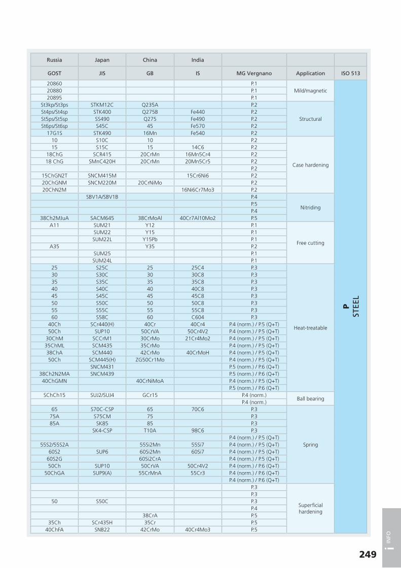
249
Russia Japan China India
GOST JIS GB IS MG Vergnano Application ISO 513
20860 P.1Mild/magnetic
PST
EEL
20880 P.120895 P.1
St3kp/St3ps STKM12C Q235A P.2
StructuralSt4ps/St4sp STK400 Q275B Fe440 P.2St5ps/St5sp SS490 Q275 Fe490 P.2St6ps/St6sp S45C 45 Fe570 P.2
17G1S STK490 16Mn Fe540 P.210 S10C 10 P.2
Case hardening
15 S15C 15 14C6 P.218ChG SCR415 20CrMn 16Mn5Cr4 P.218 ChG SMnC420H 20CrMn 20Mn5Cr5 P.2
P.215ChGN2T SNCM415M 15Cr6Ni6 P.220ChGNM SNCM220M 20CrNiMo P.220ChN2M 16Ni6Cr7Mo3 P.2
SBV1A/SBV1B P.4
NitridingP.5P.4
38Ch2MJuA SACM645 38CrMoAl 40Cr7Al10Mo2 P.5A11 SUM21 Y12 P.1
Free cutting
SUM22 Y15 P.1SUM22L Y15Pb P.1
A35 Y35 P.2SUM25 P.1SUM24L P.1
25 S25C 25 25C4 P.3
Heat-treatable
30 S30C 30 30C8 P.335 S35C 35 35C8 P.340 S40C 40 40C8 P.345 S45C 45 45C8 P.350 S50C 50 50C8 P.355 S55C 55 55C8 P.360 S58C 60 C604 P.3
40Ch SCr440(H) 40Cr 40Cr4 P.4 (norm.) / P.5 (Q+T)50Ch SUP10 50CrVA 50Cr4V2 P.4 (norm.) / P.5 (Q+T)
30ChM SCCrM1 30CrMo 21Cr4Mo2 P.4 (norm.) / P.5 (Q+T)35ChML SCM435 35CrMo P.4 (norm.) / P.5 (Q+T)38ChA SCM440 42CrMo 40CrMoH P.4 (norm.) / P.5 (Q+T)50Ch SCM445(H) ZG50Cr1Mo P.4 (norm.) / P.5 (Q+T)
SNCM431 P.5 (norm.) / P.6 (Q+T)38Ch2N2MA SNCM439 P.5 (norm.) / P.6 (Q+T)40ChGMN 40CrNiMoA P.4 (norm.) / P.5 (Q+T)
P.5 (norm.) / P.6 (Q+T)SChCh15 SUJ2/SUJ4 GCr15 P.4 (norm.)
Ball bearingP.4 (norm.)
65 S70C-CSP 65 70C6 P.3
Spring
75A S75CM 75 P.385A SK85 85 P.3
SK4-CSP T10A 98C6 P.3P.4 (norm.) / P.5 (Q+T)
55S2/55S2A 55Si2Mn 55Si7 P.4 (norm.) / P.5 (Q+T)60S2 SUP6 60Si2Mn 60Si7 P.4 (norm.) / P.5 (Q+T)
60S2G 60Si2CrA P.4 (norm.) / P.5 (Q+T)50Ch SUP10 50CrVA 50Cr4V2 P.4 (norm.) / P.6 (Q+T)
50ChGA SUP9(A) 55CrMnA 55Cr3 P.4 (norm.) / P.6 (Q+T)P.4 (norm.) / P.6 (Q+T)
P.3
Superficialhardening
P.350 S50C P.3
P.438CrA P.5
35Ch SCr435H 35Cr P.540ChFA SNB22 42CrMo 40Cr4Mo3 P.5
i INFO

M AT E R I A L E X A M P L E S
250
Germany Italy France United States
ISO 513 Application W.Nr. DIN UNI AFNOR AISI/SAE/ASTM
PST
EEL
Hot-work
1.2767 45NiCrMo16 40NiCrMoV16 KU Y35NCD161.2713 55NiCrMoV7 55NiCrMoV7 KU 55NiCrMoV7 L61.2311 35CrMo8 KU1.2365 32CrMoV12-28 30CrMoV12-27 KU 32CDV12-28 H101.2343 X38CrMoV5-1 X37CrMoV5-1 KU Z38CDV5 H111.2344 X40CrMoV5-1 X40CrMoV5-1-1 KU Z40CDV5 H131.2567 X30WCrV5-3 X30WCrV5-3 KU Z32WCV5 H141.2581 X30WCrV9-3 X30WCrV9-3 KU Z30WCV9 H21
Ferritic stainless steel
1.4002 X6CrAl13 X6CrAl13 Z 8 CA 12 4051.4512 X2CrTi12 X6CrTi12 Z 3 CT 12 4091.4016 X6Cr17 X8Cr17 Z 8 C 17 4301.4104 X14CrMoS17 X10CrS17 Z 13 CF 17 430F
Martensitic stainless steel
1.4006 X12Cr13 X12Cr13 Z 10 C 13 4101.4005 X12CrS13 X12CrS13 Z 11 CF 13 4161.4021 X20Cr13 X20Cr13 Z 20 C 13 4201.4028 X30Cr13 X30Cr13 Z 30 C 13 4201.4057 X17CrNi16-2 X16CrNi16 Z 15 CN 16-02 4311.4125 X105CrMo17 Z 100 CD 17 440C
Precipitation hardening
1.4542 X5CrNiCuNb16-4 Z 7 CNU 15-05 630
MST
AIN
LESS
STE
EL
Austenitic
1.4319 X3CrNiN17-8 X10CrNi1809 3021.4305 X8CrNiS18-9 X10CrNiS1809 Z 8 CNF 18-09 3031.4301 X5CrNi18-10 X5CrNi1810 Z 4 CN 19-10 FF 3041.4306 X2CrNi19-11 X2CrNi1811 Z 1 CN 18-12 304L1.4303 X4CrNi18-12 X8CrNi1812 Z 5 CN 18-11 FF 3051.4828 X15CrNiSi20-12 X16CrNi2314 Z 9 CN 24-13 3091.4841 X15CrNiSi25-20 X22CrNiSi2520 Z 15 CNS 25-20 3101.4401 X5CrNiMo17-12-2 X5CrNiMo1712 Z 3 CND 17-11-01 3161.4404 X2CrNiMo17-12-2 X2CrNiMo1712 Z 2 CND 17-12 316L1.4541 X6CrNiTi18-10 X6CrNiTi1811 Z 6 CNT 18-10 3211.4550 X6CrNiNb18-10 X6CrNiNb1811 Z 6 CNNb 18-10 347
Duplex1.4462 X2CrNiMoN22-5-3 X2CrNiMoN22-5-3 Z 3 CND 22-05 Az S318031.4501 X2CrNiMoCuWN25-7-4 X2CrNiMoCuWN25-7-4 S32760
KC
AST
IRO
N
Grey cast iron
0.6010 GG10 G10 Ft10D A48-20B0.6015 GG15 G15 Ft15D A48-25B0.6020 GG20 G20 Ft20D A48-30B0.6025 GG25 G25 Ft25D A48-40B0.6030 GG30 G30 Ft30D A48-45B0.6035 GG35 G35 Ft35D A48-50B0.6040 GG40 G40 Ft40D A48-60B
Nodular cast iron/ tempered
0.7040 GGG40 GS400-12 FGS400-12 60-40-180.7050 GGG50 GS500-7 FGS500-7 65-45-120.7060 GGG60 GS600-3 FGS600-3 80-55-060.7070 GGG70 GS700-2 FGS700-2 100-70-03
Malleable cast iron
0.8035 GTW35-040.8055 GTW55
Austemperedductile iron
EN-GJS-800-8EN-GJS-1000-5EN-GJS-1200-2EN-GJS-1400-1
NN
ON
-FER
RO
US
MET
ALS
Pure aluminium3.0205 Al99 9001/1 1200 (A4) 12003.0305 Al99.9
Al wrought alloys
3.0505 AlMn0.5Mg0.5 31053.0915 AlFeSi 8011 80113.3315 AlMg1 9005/1 5005 (AlMg1) 50053.3525 AlMg2Mn0.3 5251 52513.3527 AlMg2Mn0.8 5049 50493.3545 AlMg4Mn 9005/4 5086 (AG4MC) 50863.3555 AlMg53.0615 AlMgSiPb 6012
i INFO

251
Russia Japan China India
GOST JIS GB IS MG Vergnano Application ISO 513
P.5 (annealed)
Hot-work
PST
EEL
5ChNM SKT4 5CrNiMo T55Ni7Cr3Mo3V1 P.4 (annealed)P.4 (annealed)
3Ch3M3F SKD7 4Cr3Mo3SiV P.4 (annealed)4Ch5MFS SKD6 4Cr5MoSiV XT35Cr5Mo1V3 P.4 (annealed)4Ch5MF1S SKD61 4Cr5MoSiV1 XT35Cr5Mo1V1 P.4 (annealed)4Ch2W5MF SKD4 30W4Cr2VA P.4 (annealed)3Ch3W8F SKD5 3Cr2W8V XT33W9Cr3V4 P.4 (annealed)
SUS405 0Cr13Al X04Cr13 P.7Ferritic stainless
steelSUS409TB 022Cr11NbTi P.7SUS430 1Cr17 X07Cr17 P.7SUS430F Y1Cr17 P.7SUS410 1Cr13 X12Cr12 P.7
Martensitic stainless steel
SUS416 Y1Cr13 P.720Ch13 SUS420J1 2Cr13 X20Cr13 P.730Ch13 SUS420J2 3Cr13 X30Cr13 P.7
14Ch17N2 SUS431 1Cr17Ni2 X15Cr16Ni2 P.795Ch18 SUS440C 108Cr17 X108Cr17Mo P.7
SUS630/SCS24 0Cr17Ni4Cu4Nb M.2Precipitation hardening
SUS302 M.1
Austenitic
MST
AIN
LESS
STE
EL
SUS303 M.108Ch18N10 SUS304 0Cr18Ni9 X04Cr18Ni10 M.103Ch18N11 SUS304L/SCS19 00Cr19Ni10 X02Cr19Ni10 M.112Ch18N12T SUS305J1 1Cr18Ni12 M.1
SUH309 1Cr20Ni14Si2 X15Cr24Ni13 M.120Ch25N20S2 SUH310 1Cr25Ni20Si2 X20Cr25Ni20 M.108Ch16N11M3 SUS316 0Cr17Ni12Mo2 X04Cr17Ni12Mo2 M.1
SUS316L 00Cr17Ni14Mo2 X02Cr17Ni12Mo2 M.108Ch18N10T SUS321 0Cr18Ni10Ti X04Cr18Ni10Ti M.108Ch18N12B SUS347 0Cr18Ni11Nb X04Cr18Ni10Nb M.1
SUS329J3L 022Cr22Ni5Mo3N M.2Duplex
022Cr25Ni7Mo3WCuN M.2Sc10 FC10 K.1
Grey cast iron
KC
AST
IRO
N
Sc15 FC15 HT150 FG150 K.1Sc20 FC20 HT200 FG200 K.1Sc25 FC25 HT250 FG260 K.1Sc30 FC30 HT300 FG300 K.1Sc35 FC35 K.1Sc40 K.1
VC 42-12 FCD40 QT400-15 K.2Nodular cast iron
/ temperedVC 50-2 FCD50 QT500-7 SG500/7 K.2VC 60-2 FCD60 QT600-3 SG600/3 K.2VC 70-2 FCD70 QT700-2 SG700/2 K.2
K.2 Malleable cast ironK.2
K.3Austemperedductile iron
K.3K.3K.3
A1200 N.1Pure aluminium
NN
ON
-FER
RO
US
MET
ALS
N.1A3105 N.2
Al wrought alloys
N.2A5005 N.2
N.2N.2
A5086 N.2A5056 N.2
N.2
i INFO

M AT E R I A L E X A M P L E S
252
i INFO
Germany Italy France United States
ISO 513 Application W.Nr. DIN UNI AFNOR AISI/SAE/ASTM
NN
ON
-FER
RO
US
MET
ALS
Al wrought alloys
3.1255 AlCuSiMn 9002/3 2014 20143.1325 AlCuMg1 9002/2 2017 A (AU4G) 2017A3.1355 AlCuMg2 9002/4 2024 (AU4G1) 20243.1645 AlCuMgPb 9002/8 2030 (AU4PB) 20303.4335 AlZn4.5Mg1 9007/1 7020 (AZ5G) 7020
Al casting alloys
3.1371 G-AlCu4TiMg3.2134 G-AlSi5Cu1Mg3.3241 G-AlMg3Si3.3261 G-AlMg5Si3.3541 G-AlMg33.2373 G-AlSi9Mg3.2381 G-AlSi10Mg3.2383 G-AlSi10Mg(Cu)3.2581 G-AlSi123.2583 G-AlSi12(Cu)
Pure copper2.0060 E-Cu57 C110002.0065 E-Cu58 5649 CuA1 C11000
Cu wrought alloys
2.1525 CuSi3Mn CuSi3Mn1 C655002.0855 CuNi2Si CuNi2Si C647002.1247 CuBe2 Classe IV C172002.1285 CuCo2Be Classe III C17510
Brass
2.0240 CuZn152.0250 CuZn202.0265 CuZn30 C260002.0280 CuZn332.0321 CuZn37 C274502.0360 CuZn40 C280002.0410 CuZn44Pb2 CuZn43Pb2Al C380002.0550 CuZn40Al2 CuZn37Mn3Al2PbSi C67410
Bronze
2.1016 CuSn42.1020 CuSn62.1030 CuSn82.1086 G-CuSn10Zn 7013 U-E12P7U-E8Z2 C905002.0978 CuAl11Ni6Fe6 CuAl11Fe6Ni62.0940 CuAl10Fe 5274 C954002.0882 CuNi30Mn1Fe3.5312 MgAl3Zn3.5632 MgAl6Zn33.5912 MgAl9Zn13.5161 MgZn6Zr
SSU
PERA
LLO
YS
AN
D T
ITA
NIU
M
Pure titanium3.7024 Ti99.53.7034 Ti99.7
Titanium alloys3.7165 TiAl6V4 T-A6V3.7174 TiAl6V4Sn2
Pure Nickel1.3911 RNi241.3926 RNi12
Nickel alloys
2.4858 NiCr21Mo (Incoloy 825)2.4668 NiCr19Fe19NbMo (Inconel 718) INCONEL 7182.4630 Ni-Cr20Ti (Nimonic 75) NIMONIC 752.4665 NiCr22Fe18Mo (Hastelloy X)
HH
ARD
ENED
M
ATE
RIA
LS
Ball bearing1.3505 100Cr6 100Cr6 100C6 521001.3536 100CrMo6 100CrMo7 100CD7 3
Hot-work
1.2767 45NiCrMo16 40NiCrMoV16 KU Y35NCD161.2713 55NiCrMoV7 55NiCrMoV7 KU 55NiCrMoV7 L61.2311 35CrMo8 KU1.2365 32CrMoV12-28 30CrMoV12-27 KU 32CDV12-28 H101.2343 X38CrMoV5-1 X37CrMoV5-1 KU Z38CDV5 H111.2344 X40CrMoV5-1 X40CrMoV5-1-1 KU Z40CDV5 H131.2567 X30WCrV5-3 X30WCrV5-3 KU Z32WCV5 H141.2581 X30WCrV9-3 X30WCrV9-3 KU Z30WCV9 H21

253
i INFO
Russia Japan China India
GOST JIS GB IS MG Vergnano Application ISO 513
A2014 N.2
Al wrought alloys
NN
ON
-FER
RO
US
MET
ALS
A2017 N.2A2024 N.2
N.2A7N01 N.2AC1B N.2
Al casting alloys
AC4D N.3N.2N.2N.2
AC4A N.3N.4
ADC3 N.4AC3A N.4ADC1 N.4C1100 N.5
Pure copperC1100 N.5
N.6
Cu wrought alloysN.6N.6N.6N.6
Brass
N.6C2600 N.6
N.6C2700 N.6C2800 N.7
N.7N.7N.6
Bronze
N.6N.6
CAC403C (BC3) N.7N.8
CAC702C N.8N.8N.9N.9N.9N.10S.1
Pure titanium
SSU
PERA
LLO
YS
AN
D T
ITA
NIU
MS.1S.2
Titanium alloysS.2S.3
Pure NickelS.3
NCF825 S.4
Nickel alloysS.4S.4S.4
SChCh15 SUJ2/SUJ4 GCr15 H.2 (Q+T)Ball bearing
HH
ARD
ENED
M
ATE
RIA
LS
H.2 (Q+T)SKT6 H.1 (Q+T)
Hot-work
5ChNM SKT4 5CrNiMo T55Ni7Cr3Mo3V1 H.1 (Q+T)H.1 (Q+T)
3Ch3M3F SKD7 4Cr3Mo3SiV H.1 (Q+T)4Ch5MFS SKD6 4Cr5MoSiV XT35Cr5Mo1V3 H.1 (Q+T)
4Ch5MF1S SKD61 4Cr5MoSiV1 XT35Cr5Mo1V1 H.1 (Q+T)4Ch2W5MF SKD4 30W4Cr2VA H.1 (Q+T)3Ch3W8F SKD5 3Cr2W8V XT33W9Cr3V4 H.1 (Q+T)

D R I L L S I Z E C U T T I N G TA P S
254
i INFO
(*) Drill size according to DIN 336
(1) Tolerance 5H
(2) Tolerance 4H
(3) Size not included in DIN 336
ISO Metric fine threadDIN 13
M Pitch[mm]
Maximum core diam.
(tol. 6H) [mm] D1
Drill size*[mm]
M Pitch[mm]
Maximum core diam.
(tol. 6H) [mm] D1
Drill size*[mm]
M 2 (3) 0,25 1,774 (2) 1,75 M 25 1 24,153 24
2,3 (3) 0,25 2,085 2,05 25 1,5 23,676 23,5
2,5 0,35 2,221 2,15 25 2 23,210 23
3 0,35 2,721 2,65 26 1,5 24,676 24,5
3,5 0,35 3,221 3,15 27 1 26,153 26
4 0,5 3,599 3,5 27 1,5 25,676 25,5
4,5 0,5 4,099 4 27 2 25,210 25
5 0,5 4,599 4,5 28 1 27,153 27
5,5 0,5 5,099 5 28 1,5 26,676 26,5
6 0,75 5,378 5,2 28 2 26,210 26
7 0,75 6,378 6,2 30 1 29,153 29
8 0,75 7,378 7,2 30 1,5 28,676 28,5
8 1 7,153 7 30 2 28,210 28
9 0,75 8,378 8,2 30 3 27,252 27
9 1 8,153 8 32 1,5 30,676 30,5
10 0,75 9,378 9,2 32 2 30,210 30
10 1 9,153 9 33 1,5 31,676 31,5
10 1,25 8,912 8,8 33 2 31,210 31
11 0,75 10,378 10,2 33 3 30,252 30
11 1 10,153 10 35 1,5 33,676 33,5
12 (3) 0,75 11,378 11,2 36 1,5 34,676 34,5
12 1 11,153 11 36 2 34,210 34
12 1,25 10,912 10,8 36 3 33,252 33
12 1,5 10,676 10,5 38 1,5 36,676 36,5
14 1 13,153 13 39 1,5 37,676 37,5
14 1,25 12,912 12,8 39 2 37,210 37
14 1,5 12,676 12,5 39 3 36,252 36
15 1 14,153 14 40 1,5 38,676 38,5
15 1,5 13,676 13,5 40 2 38,210 38
16 1 15,153 15 40 3 37,252 37
16 1,5 14,676 14,5 42 1,5 40,676 40,5
17 1 16,153 16 42 2 40,210 40
17 1,5 15,676 15,5 42 3 39,252 39
18 1 17,153 17 45 1,5 43,676 43,5
18 1,5 16,676 16,5 45 2 43,210 43
18 2 16,210 16 45 3 42,252 42
20 1 19,153 19 48 1,5 46,676 46,5
20 1,5 18,676 18,5 48 2 46,210 46
20 2 18,210 18 48 3 45,252 45
22 1 21,153 21 50 1,5 48,676 48,5
22 1,5 20,676 20,5 50 2 48,210 48
22 2 20,210 20 50 3 47,252 47
24 1 23,153 23 52 1,5 50,676 50,5
24 1,5 22,676 22,5 52 2 50,210 50
24 2 22,210 22 52 3 49,252 49
60°P
D D1
ISO Metric coarse threadDIN 13
M Pitch[mm]
Maximum core diam.
(tol. 6H) [mm] D1
Drill size*[mm]
M 1 0,25 0,785 (1) 0,75
1,1 0,25 0,885 (1) 0,85
1,2 0,25 0,985 (1) 0,95
1,4 0,3 1,142 (1) 1,1
1,6 0,35 1,321 1,25
1,7 (3) 0,35 1,421 1,35
1,8 0,35 1,521 1,45
2 0,4 1,679 1,6
2,2 0,45 1,838 1,75
2,3 (3) 0,4 1,938 1,9
2,5 0,45 2,138 2,05
2,6 (3) 0,45 2,238 2,1
3 0,5 2,599 2,5
3,5 0,6 3,010 2,9
4 0,7 3,422 3,3
4,5 0,75 3,878 3,7
5 0,8 4,334 4,2
6 1 5,153 5
7 1 6,153 6
8 1,25 6,912 6,8
9 1,25 7,912 7,8
10 1,5 8,676 8,5
11 1,5 9,676 9,5
12 1,75 10,441 10,2
14 2 12,210 12
16 2 14,210 14
18 2,5 15,744 15,5
20 2,5 17,744 17,5
22 2,5 19,744 19,5
24 3 21,252 21
27 3 24,252 24
30 3,5 26,771 26,5
33 3,5 29,771 29,5
36 4 32,270 32
39 4 35,270 35
42 4,5 37,799 37,5
45 4,5 40,799 40,5
48 5 43,297 43
52 5 47,297 47
56 5,5 50,796 50,5
60 (3) 5,5 54,796 54,5
64 (3) 6 58,305 58
68 (3) 6 62,305 62
60°P
D D1
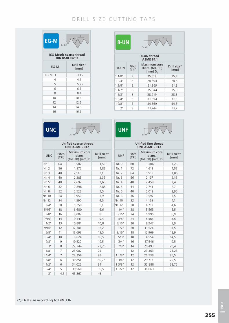
D R I L L S I Z E C U T T I N G TA P S
255
i INFO
(*) Drill size according to DIN 336
ISO Metric coarse threadDIN 8140 Part 2
EG-MDrill size*
[mm]
EG-M 3 3,15
4 4,2
5 5,25
6 6,3
8 8,4
10 10,5
12 12,5
14 14,5
16 16,5
60°P
D D1
Unified coarse threadUNC ASME - B1.1
UNC Pitch[TPI]
Maximum core diam.
(tol. 3B) [mm] D1
Drill size*[mm]
Nr. 1 64 1,582 1,55
Nr. 2 56 1,872 1,85
Nr. 3 48 2,146 2,1
Nr. 4 40 2,385 2,35
Nr. 5 40 2,697 2,65
Nr. 6 32 2,896 2,85
Nr. 8 32 3,528 3,5
Nr. 10 24 3,950 3,9
Nr. 12 24 4,590 4,5
1/4" 20 5,250 5,1
5/16" 18 6,680 6,6
3/8" 16 8,082 8
7/16" 14 9,441 9,4
1/2" 13 10,881 10,8
9/16" 12 12,301 12,2
5/8" 11 13,693 13,5
3/4" 10 16,624 16,5
7/8" 9 19,520 19,5
1" 8 22,344 22,25
1 1/8" 7 25,082 25
1 1/4" 7 28,258 28
1 3/8" 6 30,851 30,75
1 1/2" 6 34,026 34
1 3/4" 5 39,560 39,5
2" 4,5 45,367 45
60°P
D D1
Unified fine thread UNF ASME - B1.1
UNF Pitch[TPI]
Maximum core diam.
(tol. 3B) [mm] D1
Drill size*[mm]
Nr. 0 80 1,306 1,25
Nr. 1 72 1,613 1,55
Nr. 2 64 1,913 1,85
Nr. 3 56 2,197 2,15
Nr. 4 48 2,459 2,4
Nr. 5 44 2,741 2,7
Nr. 6 40 3,012 2,95
Nr. 8 36 3,597 3,5
Nr. 10 32 4,168 4,1
Nr. 12 28 4,717 4,6
1/4" 28 5,563 5,5
5/16" 24 6,995 6,9
3/8" 24 8,565 8,5
7/16" 20 9,947 9,9
1/2" 20 11,524 11,5
9/16" 18 12,969 12,9
5/8" 18 14,554 14,5
3/4" 16 17,546 17,5
7/8" 14 20,493 20,4
1" 12 23,363 23,25
1 1/8" 12 26,538 26,5
1 1/4" 12 29,713 29,5
1 3/8" 12 32,888 32,75
1 1/2" 12 36,063 36
60°P
D D1
8-UN threadASME B1.1
8-UN Pitch[TPI]
Maximum core diam. (tol. 3B)
[mm] D1
Drill size*[mm]
1 1/8" 8 25,519 25,4
1 1/4" 8 28,694 28,6
1 3/8" 8 31,869 31,8
1 1/2" 8 35,044 35,0
1 5/8" 8 38,219 38,1
1 3/4" 8 41,394 41,3
1 7/8" 8 44,569 44,5
2" 8 47,744 47,7
60°P
D D1
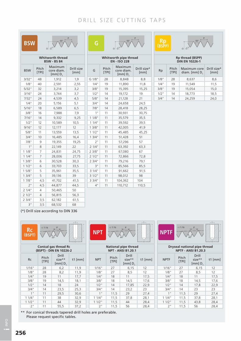
D R I L L S I Z E C U T T I N G TA P S
256
i INFO
Conical gas thread Rc(BSPT) - DIN EN 10226-2
Rc Pitch[TPI]
Drill size**
[mm] D1
t1 [mm]
1/16" 28 6,2 11,91/8" 28 8,2 11,91/4" 19 11 17,73/8" 19 14,5 18,11/2" 14 18 243/4" 14 23,5 25,3
1" 11 29,5 30,61 1/4" 11 38 32,91 1/2" 11 44 32,9
2" 11 55,5 37,2
P
55°
1:16
** For conical threads tapered drill holes are preferable. Please request specific tables.
Whitworth pipe threadEN - ISO 228
G Pitch[TPI]
Maximum core diam.
[mm] D1
Drill size*[mm]
G 1/8" 28 8,848 8,8
1/4" 19 11,890 11,8
3/8" 19 15,395 15,25
1/2" 14 19,172 19
5/8" 14 21,128 21
3/4" 14 24,658 24,5
7/8" 14 28,418 28,25
1" 11 30,931 30,75
1 1/8" 11 35,579 35,5
1 1/4" 11 39,592 39,5
1 3/8" 11 42,005 41,9
1 1/2" 11 45,485 45,25
1 3/4" 11 51,428 51
2" 11 57,296 57
2 1/4" 11 63,392 63,3
2 3/8" 11 67,080 67
2 1/2" 11 72,866 72,8
2 3/4" 11 79,216 79,1
3" 11 85,566 85,5
3 1/4" 11 91,662 91,5
3 1/2" 11 98,012 98
3 3/4" 11 104,362 104
4" 11 110,712 110,5
P
D D1
55°
Whitworth threadBSW - BS 84
BSW Pitch[TPI]
Maximum core diam.
[mm] D1
Drill size[mm]
3/32" 48 1,912 1,9
1/8" 40 2,591 2,55
5/32" 32 3,214 3,2
3/16" 24 3,744 3,7
7/32" 24 4,539 4,5
1/4" 20 5,156 5,1
5/16" 18 6,589 6,5
3/8" 16 7,988 7,9
7/16" 14 9,332 9,25
1/2" 12 10,589 10,5
9/16" 12 12,177 12
5/8" 11 13,559 13,5
3/4" 10 16,485 16,4
7/8" 9 19,355 19,25
1" 8 22,149 22
1 1/8" 7 24,831 24,75
1 1/4" 7 28,006 27,75
1 3/8" 6 30,528 30,3
1 1/2" 6 33,703 33,5
1 5/8" 5 35,961 35,5
1 3/4" 5 39,136 39
1 7/8" 4,5 41,702 41,5
2" 4,5 44,877 44,5
2 1/4" 4 50,465 50
2 1/2" 4 56,815 56,3
2 3/4" 3,5 62,182 61,5
3" 3,5 68,532 68
P
D D1
55°
Rp thread (BSPP) DIN EN 10226-1
Rp Pitch[TPI]
Maximum core diam. [mm] D1
Drill size*[mm]
1/8” 28 8,637 8,6
1/4” 19 11,549 11,5
3/8” 19 15,054 15,0
1/2” 14 18,773 18,5
3/4” 14 24,259 24,0
P
D D1
55°
(*) Drill size according to DIN 336
National pipe threadNPT - ANSI B1.20.1
NPT Pitch[TPI]
Drill size**
[mm] D1
t1 [mm]
1/16" 27 6,15 121/8" 27 8,5 121/4" 18 11 17,53/8" 18 14,5 17,61/2" 14 17,85 22,93/4" 14 23,2 23
1" 11,5 29 27,41 1/4" 11,5 37,8 28,11 1/2" 11,5 44 28,4
2" 11,5 56 28,4
60°
P 1:16
Dryseal national pipe threadNPTF - ANSI B1.20.3
NPTF Pitch[TPI]
Drill size**
[mm] D1
t1 [mm]
1/16" 27 6,15 121/8" 27 8,5 121/4" 18 11 17,53/8" 18 14,5 17,61/2" 14 17,8 22,93/4" 14 23 23
1" 11,5 29 27,41 1/4" 11,5 37,8 28,11 1/2" 11,5 43,8 28,4
2" 11,5 56 28,4
60°
P 1:16

D R I L L S I Z E F O R M I N G TA P S
257
i INFO
Other drill sizes = theorical flank diameter + pitch/5
In order to obtain the requested tolerance, the formation of a complete internal thread and guarantee the
tap tool life, it is important to respect the drill hole diameters and their tight tolerances.
The core diameter of the internal thread obtained by forming is not only a function of the drill hole diameter
but also depends on the workpiece material properties. For this reason the tolerance on the core diameter is
7H compared to 6H for cutting taps. For more detailed information see the DIN 13-50 standard.
ISO Metric coarse threadDIN 13
MPitch[mm]
Drill size[mm]
M 2 0,4 1,85 ± 0,032,5 0,45 2,30 ± 0,033 0,5 2,80 ± 0,033,5 0,6 3,25 ± 0,034 0,7 3,70 ± 0,035 0,8 4,65 ± 0,036 1 5,55 ± 0,058 1,25 7,40 ± 0,05
10 1,5 9,30 ± 0,0512 1,75 11,20 ± 0,0514 2 13,10 ± 0,0516 2 15,10 ± 0,0518 2,5 16,90 ± 0,0520 2,5 18,90 ± 0,0524 3 22,70 ± 0,0527 3 25,70 ± 0,0530 3,5 28,45 ± 0,05
60°P
D
ISO Metric fine threadDIN 13
MFPitch[mm]
Drill size[mm]
M 3 0,35 2,85 ± 0,034 0,5 3,80 ± 0,035 0,5 4,80 ± 0,036 0,75 5,65 ± 0,038 1 7,55 ± 0,05
10 1 9,55 ± 0,0510 1,25 9,40 ± 0,0512 1 11,55 ± 0,0512 1,25 11,40 ± 0,0512 1,5 11,30 ± 0,0514 1,25 13,40 ± 0,0514 1,5 13,30 ± 0,0516 1,5 15,30 ± 0,0518 1,5 17,30 ± 0,0520 1,5 19,30 ± 0,05
60°P
D
Whitworth pipe threadEN - ISO 228
G Pitch[TPI]
Drill size[mm]
G 1/8" 28 9,25 ± 0,05 1/4" 19 12,50 ± 0,05 3/8" 19 16,00 ± 0,05 1/2" 14 20,00 ± 0,05 3/4" 14 25,50 ± 0,05
1" 11 32,00 ± 0,05
P
D
55°
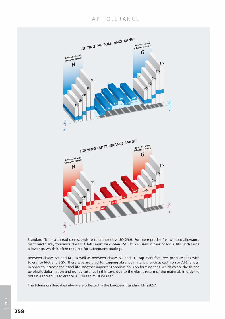
TA P T O L E R A N C E
258
i INFO
Internal thread
Tolerance class H
H
Internal thread
Tolerance class G
GCUTTING TAP TOLERANCE RANGE
Internal thread
Tolerance class H
H
Internal thread
Tolerance class G
GFORMING TAP TOLERANCE RANGE
Standard fit for a thread corresponds to tolerance class ISO 2/6H. For more precise fits, without allowance on thread flank, tolerance class ISO 1/4H must be chosen. ISO 3/6G is used in case of loose fits, with large allowance, which is often required for subsequent coatings.
Between classes 6H and 6G, as well as between classes 6G and 7G, tap manufacturers produce taps with tolerance 6HX and 6GX. These taps are used for tapping abrasive materials, such as cast iron or Al-Si alloys, in order to increase their tool life. Another important application is on forming taps, which create the thread by plastic deformation and not by cutting. In this case, due to the elastic return of the material, in order to obtain a thread 6H tolerance, a 6HX tap must be used.
The tolerances described above are collected in the European standard EN 22857.

T O L E R A N C E TA B L E
259
i INFO
Nominal diameter (mm)Pitch (mm)
Limits on pitch diameter (µm)*
Class> ≤ 4H (ISO1) 6H (ISO2) 6G (ISO3) 7G
0,99 1,4
0,2 + 15 - - -+ 5 - - -
0,25 + 17 - - -+ 6 - - -
0,3 + 18 + 30 - -+ 6 + 18 - -
1,4 2,8
0,2 + 16 - - - + 5 - - -
0,25 + 18 - - -+ 6 - - -
0,35 + 20 + 34 - -+ 7 + 20 - -
0,4 + 21 + 36 - -+ 7 + 21 - -
0,45 + 23 + 38 - -+ 8 + 23 - -
2,8 5,6
0,35 + 21 + 36 - -+ 7 + 21 - -
0,5 + 24 + 40 + 56 + 70+ 8 + 24 + 40 + 55
0,6 + 27 + 45 + 63 + 81+ 9 + 27 + 45 + 63
0,7 + 29 + 48 + 67 + 86+ 10 + 29 + 48 + 67
0,75 + 29 + 48 + 67 + 86+ 10 + 29 + 48 + 67
0,8 + 30 + 50 + 70 + 90+ 10 + 30 + 50 + 70
5,6 11,2
0,75 + 32 + 53 + 74 -+ 11 + 32 + 53 -
1 + 35 + 59 + 83 + 107+ 12 + 35 + 59 + 83
1,25 + 38 + 63 + 88 + 113+ 13 + 38 + 63 + 88
1,5 + 42 + 70 + 98 + 126+ 14 + 42 + 70 + 98
11,2 22,4
1 + 38 + 63 + 88 + 113+ 13 + 38 + 63 + 88
1,25 + 42 + 70 + 98 + 126+ 14 + 42 + 70 + 98
1,5 + 45 + 75 + 105 + 135+ 15 + 45 + 75 + 105
1,75 + 48 + 80 + 112 + 144+ 16 + 48 + 80 + 112
2 + 51 + 85 + 119 + 153+ 17 + 51 + 85 + 119
2,5 + 54 + 90 + 126 + 162+ 18 + 54 + 90 + 126
22,4 45
1 + 40 + 66 + 92 + 118+ 13 + 40 + 66 + 92
1,5 + 48 + 80 + 112 + 144+ 16 + 48 + 80 + 112
2 + 54 + 90 + 126 + 162+ 18 + 54 + 90 + 126
3 + 64 + 106 + 148 + 190+ 21 + 64 + 106 + 148
3,5 + 67 + 112 + 157 + 202+ 22 + 67 + 112 + 157
4 + 71 + 118 + 165 + 212+ 24 + 71 + 118 + 165
4,5 + 75 + 125 + 175 + 225+ 25 + 75 + 125 + 125
45 90
1,5 + 51 + 85 + 119 + 153+ 17 + 51 + 85 + 119
2 + 57 + 95 + 133 + 171+ 19 + 57 + 95 + 133
3 + 67 + 112 + 157 + 202+ 22 + 67 + 112 + 157
4 + 75 + 125 + 175 + 225+ 25 + 75 + 125 + 175
5 + 80 + 133 + 186 + 239+ 27 + 80 + 133 + 186
5,5 + 84 + 140 + 196 + 252+ 28 + 84 + 140 + 196
6 + 90 + 150 + 210 + 270+ 30 + 90 + 150 + 210
(*) According to EN 22857

260
i INFO
I CO N D E S C R I P T I O N
TAP AND DIE GEOMETRY
HOLE TYPE AND DEPTH
Tap with straight flutes and spiral point
Tap with straight flutes with interrupted thread
Tap with 15° left hand spiral
Forming tap with oil grooves
Through coolant tap with internal axial hole, for blind holes
Through coolant tap with internal axial and radial holes, for through holes
Through coolant forming tap with internal axial hole, for blind holes
Through coolant forming tap with internal axial and radial holes, for through holes
Hand tap
Tap with straight flutes
Tap with straight flutes and spiral point withinterrupted thread
Tap with 15° right hand spiral
Tap with 40° right hand spiral and 2 flutes
Tap with 40° right hand spiral
Tap with 45° right hand spiral
Forming tap without oil grooves
Through coolant tap with internal axial hole, for blind holes
Thread Mills with internal axial coolant
Thread Mills with internal radial coolant
Tap with long shank
Tap with through shank
Die
Through
Through, up to 1 x d1
Blind, up to 2 x d1
Blind, up to 2,5 x d1
Through, up to 3 x d1
Through, up to 1,5 x d1
Through, up to 2,5 x d1
Blind, up to 3 x d1
Blind and through, up to 2 x d1
Blind
Blind, up to 1,5 x d1
Blind and through
Blind and through, up to 1,5 x d1
Blind and through, up to 2,5 x d1
Tapered hole
Blind and through, up to 3 x d1
Back tapering
Tap with 40° right hand spiralLeft hand cut
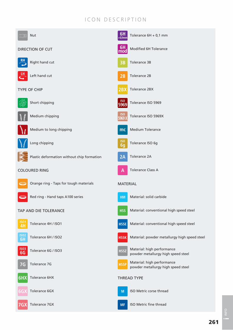
261
i INFO
I CO N D E S C R I P T I O N
THREAD TYPE
DIRECTION OF CUT
TYPE OF CHIP
COLOURED RING
MATERIAL
Right hand cut
Left hand cut
Short chipping
Orange ring - Taps for tough materials
Medium chipping
Plastic deformation without chip formation
Medium to long chipping
Long chipping
Medium Tolerance
Tolerance 2BX
Tolerance ISO 5969
Tolerance 2A
Tolerance Class A
Modified 6H Tolerance
Tolerance 2B
Tolerance ISO 5969X
Tolerance ISO 6g
Material: solid carbide
Material: conventional high speed steel
Material: conventional high speed steel
ISO Metric corse thread
ISO Metric fine thread
Material: high performancepowder metallurgy high speed steel
Material: powder metallurgy high speed steel
Material: high performancepowder metallurgy high speed steel
Tolerance 3B
Nut
TAP AND DIE TOLERANCE
Tolerance 6G / ISO3
Tolerance 7G
Tolerance 4H / ISO1
Tolerance 6H / ISO2
Tolerance 6HX
Tolerance 7GX
Tolerance 6H + 0,1 mm
Tolerance 6GX
Red ring - Hand taps A100 series
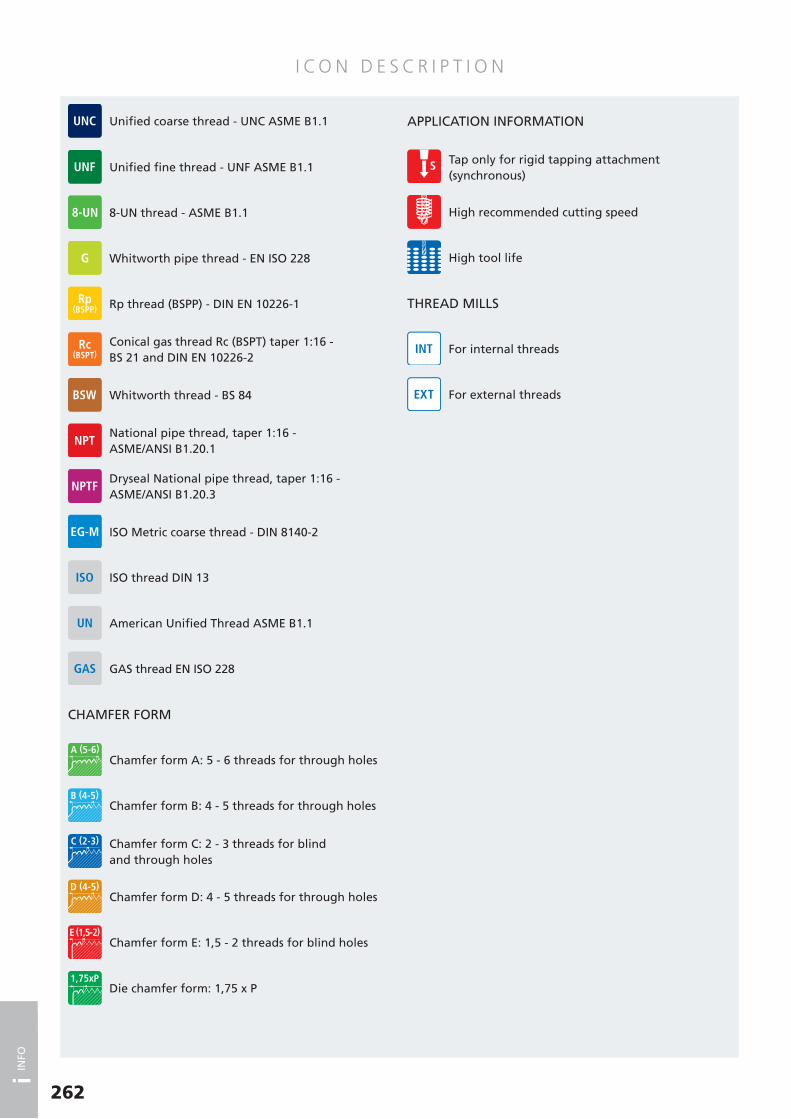
I CO N D E S C R I P T I O N
262
i INFO
CHAMFER FORM
THREAD MILLS
Whitworth thread - BS 84
ISO Metric coarse thread - DIN 8140-2
GAS thread EN ISO 228
Unified fine thread - UNF ASME B1.1
Conical gas thread Rc (BSPT) taper 1:16 -BS 21 and DIN EN 10226-2
Dryseal National pipe thread, taper 1:16 - ASME/ANSI B1.20.3
American Unified Thread ASME B1.1
Whitworth pipe thread - EN ISO 228
Rp thread (BSPP) - DIN EN 10226-1
National pipe thread, taper 1:16 -ASME/ANSI B1.20.1
ISO thread DIN 13
Chamfer form C: 2 - 3 threads for blind and through holes
Chamfer form D: 4 - 5 threads for through holes
For internal threads
High recommended cutting speed
For external threads
Chamfer form A: 5 - 6 threads for through holes
Chamfer form B: 4 - 5 threads for through holes
Chamfer form E: 1,5 - 2 threads for blind holes
High tool life
Die chamfer form: 1,75 x P
8-UN thread - ASME B1.1
Unified coarse thread - UNC ASME B1.1 APPLICATION INFORMATION
Tap only for rigid tapping attachment (synchronous)

Graphic design by:
StudioAlmayernChieri - Torino - Italy
Printed by:
IlTipografoRiva presso Chieri - Torino - Italy
Printed 08/2019
Printed on Certified Ecological Paper

I N D E XTOOL CODE LIST
A SERIES
TOOL CODE Thread Page
A1 M 34A1 LH M 36A2 MF 79A2 LH MF 82A4 BSW 131A5 G 121A6 Rc (BSPT) 130A6 B NPT 134A6 BZ NPT 135A6 F NPTF 136A6 FZ NPTF 137A7 UNC 103A8 UNF 111A9 M 73A10 MF 98A15 AZ M 52A15 AZ TiH1 M 52A15 L M 53A15 L TiN M 53A15 S M 45A15 S VAP M 45A15 S TiN M 45A15 S TiCN M 45A15 S 4H M 47A15 S 4H TiN M 47A15 S 6G M 48A15 S 6G TiN M 48A15 S 7G M 49A15 S 7G TiN M 49A15 S LH M 50A15 S LH TiN M 50A16 S M 51A16 S TiN M 51A17 S MF 87A17 S VAP MF 87A17 S TiN MF 87A17 S TiCN MF 87A17 S TiX2 MF 90A17 S 6G MF 91A17 S 6G TiN MF 91A18 S G 124A18 S VAP G 124A18 S TiCN G 124A18 S TiX2 G 124A19 S UNC 106A19 S TiN UNC 106A19 S TiCN UNC 106A19 S 3B UNC 106A19 S TiX2 UNC 107A20 S UNF 114A20 S TiN UNF 114A20 S TiCN UNF 114A20 S 3B UNF 114A20 S TiX2 UNF 115A21 FC M 38A21 FC TiN M 38A22 FC M 40A22 FC TiN M 40A23 FC MF 83A23 FC TiN MF 83A23 FC LH MF 83A24 FC BSW 132A24 FP BSW 132A26 FC G 122A26 FP G 122A27 FC UNC 104A27 FC TiN UNC 104A27 FP UNC 104A27 FP TiN UNC 104A28 FC UNF 112A28 FC TiN UNF 112A28 FP UNF 112A28 FP TiN UNF 112A29 M 55A29 VAP M 55A29 TiN M 55A29 6G M 57
A SERIES
TOOL CODE Thread Page
A29 6G TiN M 57A29 DIN 376 M 58A29 DIN 376 TiN M 58A29 L M 59A29 L TiN M 59A30 MF 92A30 TiN MF 92A31 BSW 133A31 TiN BSW 133A32 G 125A32 TiN G 125A33 UNC 108A33 TiN UNC 108A33 3B UNC 108A34 UNF 116A34 TiN UNF 116A34 3B UNF 116A43 NITR. M 41A43 TiCN M 41A44 NITR. M 42A44 TiCN M 42A45 NITR. MF 86A45 TiCN MF 86A48 NITR. G 123A48 TiCN G 123A49 NITR. UNC 105A49 TiCN UNC 105A50 NITR. UNF 113A50 TiCN UNF 113A59 S G 126A59 S VAP G 126A59 S TiN G 126A59 S TiCN G 126A59 S TiX2 G 127A60 S UNC 109A60 S TiN UNC 109A60 S TiCN UNC 109A60 S TiX2 UNC 109A61 S UNF 117A61 S TiN UNF 117A61 S TiCN UNF 117A61 S TiX2 UNF 117A62 M 71A62 TiH1 M 71A65 UNC 110A66 UNF 118A67 M 43A67 TiH1 M 43A70 L M 68A70 L TiN M 68A70 S M 60A70 S VAP M 60A70 S TiN M 60A70 S TiCN M 60A70 S 4H M 61A70 S 4H TiN M 61A70 S 6G M 62A70 S 6G TiN M 62A70 S 7G M 63A70 S 7G TiN M 63A70 SE M 65A70 SE TiN M 65A70 S LH M 66A70 S LH TiN M 66A71 S MF 95A71 S VAP MF 95A71 S TiN MF 95A71 S TiCN MF 95A71 S TiX2 MF 96A71 S 6G MF 97A71 S 6G TiN MF 97A72 M 72A72 TiH1 M 72A76 S M 67A76 S TiN M 67A80 TiN M 74A80 TiCN M 74
A SERIES
TOOL CODE Thread Page
A80 6GX TiN M 75A80 6GX TiCN M 75A80 N TiN M 76A80 N TiCN M 76A80 N 6GX TiN M 77A80 N 6GX TiCN M 77A81 TiN MF 99A81 TiCN MF 99A81 6GX TiN MF 100A81 6GX TiCN MF 100A81 N TiN MF 101A81 N TiCN MF 101A81 N 6GX TiN MF 102A81 N 6GX TiCN MF 102A82 N TiN G 128A82 N TiCN G 128A100 M 37A110 VAP M 44A110 CrN M 44A119 8-UN 119A119 TiN 8-UN 119A120 M 69A120 VAP M 69A120 TiN M 69A150 VAP M 54A150 TiX2 M 54A159 S Rp (BSPP) 129A159 S TiN Rp (BSPP) 129A160 8-UN 120A160 TiN 8-UN 120A170 VAP M 70A170 TiX2 M 70A190 EG-M 78A701 S M 64A701 S TiN M 64
F.LLI VERGNANO S.r.l. Corso Egidio Olia, 210023 Chieri - TO - ItalyTe l . +39 0119423523Fax . +39 0119425426i n f o @ v e r g n a n o . c o m
# 75
EN
G E N E R A L C A T A L O G U Et a p s - d i e s
t h r e a d m i l l s - t a p p i n g a t t a c h m e n t s
# 75 EN
INTRODUCTION
New Products Catalogue n° 75 6
Guide to Tap Application Table 8
Guide to Tap Datasheets 9
Guide to Thread Mills Datasheets 10
Guide to Tapping Attachments Datasheets 11
Guide to TappFinder App 12
Tap Application Table 14
“A” SERIES - TAPS FOR GENERIC APPLICATIONS
M ISO Metric coarse thread - DIN 13 34
EG-M ISO Metric coarse thread (for wire inserts) - DIN 8140-2 78
MF ISO Metric fine thread - DIN 13 79
UNC Unified coarse thread - ASME B1.1 103
UNF Unified fine thread - ASME B1.1 111
8-UN Unified constant pitch series thread - ASME B1.1 119
G Gas Whitworth thread - EN ISO 228 121
Rp Rp thread (BSPP) - DIN EN 10226-1 129
Rc Conical gas thread (BSPT), taper 1:16 - BS 21 and DIN EN 10226-2 130
BSW Whitworth thread - BS 84 131
NPT National pipe thread, taper 1:16 - ASME/ANSI B1.20.1 134
NPTF Dryseal National pipe thread, taper 1:16 - ASME/ANSI B1.20.3 136
“P” SERIES - HIGH PERFORMANCE TAPS
M ISO Metric coarse thread - DIN 13 140
MF ISO Metric fine thread - DIN 13 157
G Gas Whitworth thread - EN ISO 228 164
“S” SERIES - SYNCHRONOUS TAPS
M ISO Metric coarse thread - DIN 13 168
MF ISO Metric fine thread - DIN 13 172
“H” SERIES - SOLID CARBIDE TAPS
M ISO Metric coarse thread - DIN 13 176
MF ISO Metric fine thread - DIN 13 180
“F” DIES
M ISO Metric coarse thread - DIN 13 204
MF ISO Metric fine thread - DIN 13 205
UNC Unified coarse thread - ASME B1.1 208
UNF Unified fine thread - ASME B1.1 209
G Gas Whitworth thread - EN ISO 228 210
BSW Whitworth thread - BS 84 211
NPT National pipe thread, taper 1:16 - ASME/ANSI B1.20.1 212
DISCONTINUED TAPS 184
THREAD MILLS
ISO Thread milles carbide 217
UN Thread milles carbide 220
GAS Thread milles carbide 223
SYNCHRONOUS TAPPING ATTACHMENTS
Synchronous Tapping Attachments 228
Accessories 232
TECHNICAL INFORMATION 238