GENERAL CATALOGUE - Sodeca
440
GENERAL CATALOGUE HEAD OFFICE Ctra. de Berga, km 0,7 E-08580 SANT QUIRZE DE BESORA Barcelona - SPAIN Tel. +34 93 852 91 11 Fax +34 93 852 90 42 General sales: [email protected] Export sales: [email protected]
-
Upload
khangminh22 -
Category
Documents
-
view
2 -
download
0
Transcript of GENERAL CATALOGUE - Sodeca

GENERAL CATALOGUE
HEAD OFFICECtra. de Berga, km 0,7E-08580 SANT QUIRZE DE BESORABarcelona - SPAINTel. +34 93 852 91 11Fax +34 93 852 90 42General sales: [email protected] sales: [email protected]

SODECA focuses its business activity on the manufacture of in-dustrial fans, ventilation systems and smoke extractor fans for fire protection since it was set up in 1983.
The fans and extractor fans manufactured by SODECA are pre-sent in Europe and in many other parts of the world due to their quality and the research and development methods used.
Our quality procedures, certified by BUREAU VERITAS in accord-ance with ISO 9001:2015, are another reason why SODECA is positioned as one of the best and most recognised fan manufac-turer in Europe.
There is no doubt that the most important element in achieving our objectives is the human factor and the professionals who work in the company and offer not only ventilation equipment but solu-tions to all the needs of our customers in the ventilation sector.
We offer them the option of visiting our facilities in Sant Quirze de Besora, with a developed surface area of more than 16,000 m2, to see our fan production plant, which complies with the highest quality requirements and with the ISO and AMCA standards.
This catalogue contains just a few of all the options we offer. Please contact us and we will place all our experience and staff at your disposal.
SODECA S.L.U. main facilities in E-08580 SANT QUIRZE DE BESORA
Sodeca has begun a new stage of study and design of new trends in ventilation which will help to preserve the environment and to make the energy saving which so much concerns today’s society.
SODECA is pleased to present its new efficient, high performance “Efficient Work” fans, equipped with high-tech motors for greater energy savings. These new products exceed the requirements of the Ecodesign ErP Directive of 2009/125/CE and the (EU) regulation 327/2011 governing fans and adhere to the KYOTO goals adopted by the EU for cutting greenhouse gas emissions.
OUR COMMITMENT TO THE ENVIRONMENT
EFFICIENT WORK

INDUSTRIAL FANS AND EXTRACTOR UNITS
Since it was first established, Sodeca has specialised in the design and manufacture of fans and their acces-sories for industrial applications.
The combination of its experience gained over dec-ades of working with fans and the technology provided by the engineers employed in its different departments has allowed Sodeca to occupy a leading international position as a fan manufacturer.
Industrial applications require an important capacity to adapt to the specifications of each project and flex-ibility in production in order to comply with the real needs of each client.
To comply with this objective, Sodeca has a standard products line and a specially-manufactured products line for building fans that meet the demands of our clients.
For many years, we have constantly invested in the development of processes and applications aimed at manufacturing and supplying special industrial fans with extremely tight deadlines in terms of their design and production.
The teamwork of our engineering department, in con-junction with universities and technological centres, and the close cooperation between the design depart-ments of our external partners has made it possible to obtain new industrial fan solutions in a very short space of time.
During our history, we have developed all manner of fan technology for industrial applications in all parts of the world. Our aim is to continue to invest in this sec-tor in order to become one of the most reputed global industrial fan manufacturers.

4
IN-LINE DUCT EXTRACTOR FANS
AXIAL EXTRACTOR FANS
12
26
SVE
HC
HFWHCT/IMP-C HCT/IMP
EDMFSVE/PLUS
HGI
HTP
NEOLINEO/V
HCD
HGT HGTX
NEOSILENT
HCH
HPX
HCT
HBA
13
27
5349 51
2413
33
58
19
35
71
21
37
98
37
101
Wall-mounted axial fanswith IP55 motors
In-line duct extractor fans
In-line duct extractor fanswith 40-mmacousticinsulation
Axial fans with large diameters
Wall-mounted axial fans with small diameters
Extremely robust wall-mounted, tubular, axial fans
Extremely robust wall-mounted, tubular, axial fans
Hot dip galvanised tubular fans
Long-range, circular, one-way or reversible jet fans
Long-range one-way or reversible jet fans
High pressure tubular axial extractor fans
Tubular axial fans with largediameters and direct drive motors.
Tubular axial fans with external motors
Forked tubular axial fans
Small, in-line duct extractor fans with a detachable body
In-line duct extractor fanswith a low noise level
Extra-flat bathroom extractor fans with a modern appearance and design

5
CENTRIFUGAL EXTRACTOR FANS 103
CMXCI-CO
CBXC CDXR
CJSXR
CBD
CBXR
CDXRT
TSA
CBXT
CJDXR
TSAT
CJBD/ALG
CSXR
CJTSA
CBX
CJBX/ALG
CSXRT
CMP
107106
122 140
149
116
122
140
161
122
140
161
119
149
161
122
132
149
169
CMR
CAS-SCMA CPV CA CAS
177
193182 185 190 193
VENT-SET belt-drivencentrifugal extractor fans fitted with reactionimpeller
Long-range, low profile, centrifugal induction jet fans
Centrifugal,double inlet,belt-driven fans
Centrifugal,double inlet,belt-driven fans
Centrifugal,double inlet,belt-driven fans
Belt-driven ventilation units made of aluminium profiles and galvanised sheet steel with acoustic insulation
Low-pressure, double inlet, centrifugal fans with direct-drive motors
Ventilation units made of aluminium profiles and galvanised sheet steel with acoustic insulation
Centrifugal,double inlet, belt-drivenfans
Double inlet, belt-driven fans
Single inlet, belt-drivenventilationunits a transmisión
Extremely robust, medium pressure,centrifugal fans
High pressure, centrifugal,fans made ofsheet steelwith acousticattenuators
Medium pressure,centrifugal fanswith cast aluminiumimpeller
Centrifugal fansmade of anti-corrosiveplastic material
High pressure centrifugal fansmade of cast aluminium
High pressurecentrifugal fansmade of sheet steel
Single inlet,belt-driven fans
Single inlet,belt-driven fans
Single inlet, belt-drivenventilationunits
Medium pressure,centrifugal fansfitted withsheet steel or aluminiumimpeller
Double inlet, belt-driven fans
Double inlet,belt-drivenventilationunits
Single inlet, belt-drivenfans
Single inlet,belt-driven fans

6
STAIRCASE OVERPRESSURE KIT 362
KIT SOBREPRESIÓN KIT BOXPDS HATCH PDS
369 373 375
F-300 AND F-400 EXTRACTOR FANS FOR SMOKE EVACUATION IN CAR PARKS AND SIMILAR 261
THT
TCR/R
THT/IMP
CJTCR/R
CI
CJTX-C
HTMF
CJSX
THT/ROOF
CSX
266
334
319
334
323
339
324
347
331
353
F-400 CERTIFICATION
F-400
400 ºC/2h and 300 ºC/2h roof-mounted multifunctional extractor fans
400 ºC/2h and 300 ºC/2htubular axial extractor fans
400 ºC/2h centrifugal extractor fanwith reaction impeller
Pressurisationsystem forstaircases,escape routes or confinement
Pressurisationequipmentfor staircases,escape routesand fire fighting lobbies
Pressurisationequipmentfor staircases,escape routesand fire fighting lobbies
400 ºC/2h extractor fan units with reactionimpeller
400 ºC/2h extractor fan units with motor and belt drive insidebox
400 ºC/2h belt-driven, single inlet extractor fan units
400 ºC/2h belt-driven centrifugalextractor fans with reaction impeller
300 ºC/2h and 400 ºC/2h long range, induction centrifugal fans
300 ºC/2h and 400 ºC/2h long-range one-way or reversible jet fans with a circular or anoctagonal design
400 ºC/2h and 300 ºC/2h roof-mounted axial extractor fans with vertical air outlet
ROOF-MOUNTED EXTRACTOR FANS 199
VC-HDU
HTMH
RFHCXT
HTMV
RFV CRF
HT
202
227
216211
234
216 221
224
Roof-mounted centrifugal ex-tractor fans, with low noise level
Centrifugal roof-mounted extractor fans, with vertical air outlet
400 ºC/2h centrifugal roof-mounted extractor fans, with horizontal air outlet
Roof-mounted, belt-driven centrifugal fans with a vertical or horizontal air impulsion design
400 ºC/2h centrifugal roof-mounted extractor fans, with vertical air outlet
Roof-mounted axial extractor fans with flat bases
Roof-mounted multifunctional extractor fans for large flow rates
Roof-mounted axial extractor fans with vertical air outlet

7
AIR CURTAINS 433
ATEX EXTRACTOR FANS FOR EXPLOSIVE ATMOSPHERES
HEAT RECOVERY UNITS · AIR FILTER AND TREATMENT UNITS
378
401
HCDF
RECUP
ECONOMIC
CMP/ATEX
HDF
SV/FILTER
CMR/ATEX
HCH/ATEX
UFR
HCT/ATEX
UDT
CMA/ATEX
UDTX
385
407
435
394
385
411
398
388
415
388
419
392
425
ATEX CERTIFIED
Axial extractor fans with a square frame and ATEX Ex dcertification
Wall-mountedmedium pressure,centrifugal fansfitted with multi-bladeimpeller and withATEX certification
Axial fanswith a circular frame andATEX Ex dcertification
Extremely robust,medium pressure,centrifugal extrac-tor fans fitted withreaction impeller and with ATEXcertification
Extremely robust, wall-mountedaxial extractor fans withATEX certification
Extremely robust, wall-mountedaxial extractor fans withwith ATEXcertification
Medium pressure,centrifugalfans made of cast aluminium, with ATEXcertification
Configurable heat recovery units with cross-flow plates for horizontal (H) or vertical (V)installation
Low-noise, in-line duct extractor fans with different filtering phases.
Filter units acoustically insulated with sandwich panel
Ventilation units with air treatment systems and direct drive motors
Belt-driven ventilation units with air treatment systems
Economical air curtains for small commercial establishments.

Easysearch
PROJECT MODULEPrepare technical reports in minutes. Select hundreds of models in a single step. Mass load your data in Excel.. Edit and process the technical data sheets.· Print out the report with a contents table and cover, edit it or send it to another QuickFan. OVERPRESSURE CALCULATION
IN STAIRCASE AREAS· Rapid calculation of the necessary staircase over pressure flow rate for the most common systems, in accordance with UNE-EN 12101:2006.· Easily configure the design for each floor or for evacuation route areas.
3D CAD MODELS. Download our fans in 3D Cad from our website.. Choose from among more than 40 available Cad formats, including Revit.. More than 2,000 models and configurations available.
Personalisereports
Alwaysupdated
Reports inminutes
ModelsCAD 3D
Formatsavailable
Alwaysupdated
Reports inminutes
NEW TOOLFOR ENGINEERING FIRMS AND
TECHNICAL DEPARTMENTS
Available in:

SODECA fans and extractors comply with the following standards:
QUALITY ISO 9001:2015 Sistemas de gestión de la calidad. Requisitos. Quality management systems -- Requirements
TRIALS UNE-EN ISO 5801 Ventiladores industriales. Ensayos de comportamiento en circuitos normalizados. Industrial fans -- Performance testing using standardized airwaysAMCA 210-07 Ventiladores industriales. Métodos de ensayos de ventiladores y su representación de ensayos. Laboratory Methods of Testing Fans for Aerodynamic Performance Rating UNE EN ISO 13350 Ventiladores industriales. Ensayos de comportamiento de ventiladores de chorro. Industrial fans -- Performance testing of jet fansISO 13348 Industrial fans -- Tolerances, methods of conversion and technical data presentation
HIGH TEMPERATURE FANS EN 12101-3 Sistemas de control de humos y calor. Parte 3: Especificaciones para aireadores extractores de humos y calor mecánicos. Smoke and heat control systems - Part 3: Specification for powered smoke and heat exhaust ventilators
ACOUSTICS EN ISO 3744 Acústica. Determination of the acoustic power levels of noise sources based on acoustic pressure. Método de ingeniería para condiciones de campo libre sobre un plano reflectante. Acoustics -- Determination of sound power levels of noise sources using sound pressure. Engineering method in an essentially free field over a reflecting plane
BALANCING AND VIBRATIONS ISO 1940-1 Vibraciones mecánicas. Calidad de equilibrado Mechanical vibration -- Balance quality requirements for rotors in a constant (rigid) state -- Part 1: Specification and verification of balance tolerances ISO 10816-1 Vibraciones mecánicas. Evaluación de las vibraciones de máquinas Mechanical vibration -- Evaluation of machine vibration by measurements on non-rotating parts -- Part 1: General guidelines ISO 14694 Ventiladores industriales. Especificaciones para equilibrado y niveles de vibración Industrial fans -- Specifications for balance quality and vibration levels
SAFETY (EC Declaration of Conformity) EN ISO 12100-1 Seguridad de las máquinas. Conceptos básicos, principios generales para el diseño. Parte 1: Terminología básica, metodología. Safety of machinery -- Basic concepts, general principles for design -- Part 1: Basic terminology, methodology EN ISO 12100-2 Seguridad de las máquinas. Conceptos básicos, principios generales para el diseño. Parte 2: Principios técnicos. Safety of machinery -- Basic concepts, general principles for design -- Part 2: Technical principles UNE EN 60204-1 Seguridad de las máquinas. Equipo eléctrico de las máquinas. Parte 1: Requisitos generales. Safety of machinery - Electrical equipment of machines - Part 1: General requirements EN ISO 13857 Seguridad de máquinas. Distancias de seguridad para impedir que se alcancen zonas peligrosas con los miembros superiores e inferiores. Safety of machinery -- Safety distances to prevent danger zones being reached by upper and lower limbs UNE EN ISO 12499 Ventiladores industriales. Seguridad mécanica en los ventiladores Industrial fans -- Mechanical safety of fans -- Guarding
DIRECTIVES AND REGULATIONS Directive 2006/42/CE Directiva de máquinas Machinery DirectiveDirective 2014/35/UE Directiva de baja tensión Low Voltage DirectiveDirective 2014/30/UE Directiva compatibilidad electromagnética EMC DirectiveRegulation 305/2011 Directiva productos de construcción Construction Products Directive (CPR)Directive 2009/125/CE Directiva de requisitos de diseño ecológico para productos que utilizan energía. Ecodesign Requirements for Energy-related Products Directive AEX EXECUTIONS ATEX directive 2014/34/UE Aparatos y sistemas de protección para uso en atmósferas potencialmente explosivas Equipment and protective systems intended for use in potentially explosive atmospheresEN 14986 Diseño de ventiladores para trabajar en atmósferas potencialmente explosivas. Design of fans working in potentially explosive atmospheresEN 13463-1 Equipos no eléctricos destinados a atmósferas potencialmente explosivas. Parte 1: Requisitos y metodología básica. Non-electrical equipment for use in potentially explosive atmospheres - Part 1: Basic method and requirementsEN 1127-1 Explosive atmospheres. Prevención y protección contra la explosión. Parte 1: Conceptos básicos y metodología. Explosive atmospheres - Explosion prevention and protection - Part 1: Basic concepts and methodology
COMPLIANCE WITH STANDARDS

StaffEmpleadosPersonnelPersonal
WORLD WIDE
350Presence on 5 continents Presencia en 5 continentesPrésence sur 5 continentsPräsenz auf 5 Kontinenten5Production plants Plantas de producciónUsines de productionFertigungsanlagen5European Centre for Research Centro europeo de InvestigaciónCentre européen pour la rechercheEuropäisches Zentrum für die Forschung1Commercial presence in 117 countries Presencia comercial en 117 paisesLa présence commerciale dans 117 pays Kommerzielle Präsenz in 117 Ländern117World BranchesFiliales en el mundoImplantations mondialesNiederlassungen7
ISO 9001:2015 QualityCalidadQualitéQualität
AMCA 210-07 TrialsEnsayosEssaisStudien
EN-12101-3 Trials temperature Ensayos temperaturaEssais température Test Temperatur
ISO 3744 AcousticAcusticaAcoustiqueAkustisch
ISO 1940-1 BalancedEquilibradoÉquilibréAusgeglichen
EN-ISO 12100 SecuritySeguridadSécuritéSicherheit
Directive 2009/125/EC
DirectivesDirectivasDirectivesRichtlinien
EN-14986 ATEXProducts in catalogueProductos en catálogoProduits du catalogueProdukte im Katalog4200
Erp 2015/2016/2018 Efficiency EficienciaEfficacitéLeistungsfähigkeit
F-400

Continents
5Commercial presence
in 117 countries
117World Branches
7Production plants
5
PORTUGAL Sodeca Portugal LdaPORTORua Veloso Salgado 1120/11384450-801 Leça de Palmeira,Tel. +351 229 991 100Fax. +351 229 991 [email protected]
Finland
FINLANDSodeca Finland OyMr. Kai Yli-SipiläMetsälinnankatu 30, PL2,FI-32700 HUITTINEN, FINLANDTel. + 358 400 320 [email protected]
PERUSodeca Perú SACMr. José Luis JiménezTel. +51 1 4216486Cell +51 [email protected]
Production plantProduction plant
SUBSIDIARIES
SANT QUIRZE DE BESORABarcelona - SPAIN
MADRIDSPAIN
TORELLÓBarcelona - SPAIN
PRODUCTIONPLANTS
Production plant
BOGOTÁCOLOMBIA
Sodeca S.L.U. Ctra. de Berga, km 0,7E-08580 SANT QUIRZE DE BESORABarcelona, SPAINTel. +34 93 852 91 11Fax +34 93 852 90 42General sales: [email protected] sales: [email protected]
HEAD OFFICE
Chile
CHILESodeca Ventiladores LtdaMr. Frederic CousquerSanta Bernardita 12.005(Esquina con Puerta Sur)Bodegas 24 a 26San Bernardo, Santiago, CHILETel. +56 22 840 [email protected]
Production plant
SANTIAGO DE CHILECHILE
COLOMBIASodeca Latam S.A.SSra. Luisa Stella PrietoCalle7 No. 13 A-44 Manzana 4 Lote 1Mosquera Cundinamarca Bogotá, COLOMBIATel. +57 1 756 [email protected]
Russia Fans UK
PORTUGAL Sodeca Portugal LdaLISBOAParque Empresarial da GranjaPavilhão 82625-607 Vialonga, Tel. +351 219 748 491 Fax. +351 219 748 [email protected]
UNITED KINGDOMSodeca Fans UK LtdMr. Mark NewcombePacific HouseRelay Point Tamworth, B77 5PAUNITED KINGDOMTel. +44 (0) 1827 264 435Mob. +44 (0) 7488 [email protected]
RUSSIASodeca, L.L.C.Mr. Stanislav AlifanovMyasischeva str, 1, room 603Business Сenter “Chaika”140180 Zhukovskiy, Moscow, RUSSIATel. +7 495 955 90 [email protected]
Perú

12
IN-LINE DUCT EXTRACTOR FANS
SVE EDMFSVE/PLUS NEOLINEO/V NEOSILENT
13 2413 19 21
In-line duct extractor fans
In-line duct extractor fanswith 40-mmacousticinsulation
Small, in-line duct extractor fans with a detachable body
In-line duct extractor fanswith a low noise level
Extra-flat bathroom extractor fans with a modern appearance and design

13
SVE: Low-noise, in-line duct extractor fans mounted inside an acoustic casingSVE/PLUS: In-line, low noise duct fans mounted inside a 40 mm Phonoabsorbent acoustic casing
SVESVE/PLUS
Fan:• Acoustic casing coated with phonoabsorbent material.• Impeller with reaction blades except models
100-125-150-160-200/H, with multi-blade impeller.• Standardised intake and impulsion flanges
allowing for easy installation in ducts.• Fitted with a folding inspection cover, except models
100-125-150/L-160/L.• Support feet built into the box, for easy installation.• Linear air flow direction.
Motor:• External rotor motors with built-in thermal protector,
class F, with ball bearings, IP54 protection.• Adjustable, single-phase 220V 60Hz.• Maximum temperature of air to be carried: +50 ºC.
Finish:• Anti-corrosive galvanised sheet steel.
Order code
Technical characteristicsSpeed
(r/min)
Model Maximum admis-sible current 220V
(A)
Max. electric
power (kW)
Maximum flow rate
(m3/h)
Irradiated sound level
dB(A)
Approx. weight
(kg)
SVE-100/L 2160 0.45 0.10 290 44.10 5.5 ForwardSVE-125/H 2676 0.75 0.18 370 55.65 6.0 ForwardSVE-125/L 1800 0.45 0.10 310 45.15 5.5 ForwardSVE-150/H 2160 1.00 0.25 490 54.60 7.0 ForwardSVE-150/L 2160 0.45 0.10 355 54.60 6.0 ForwardSVE-160/H 2700 1.00 0.25 490 54.60 7.0 ForwardSVE-200/H 1680 0.75 0.18 760 44.10 12.0 ForwardSVE-200/L 3180 0.70 0.18 640 50.48 9.0 BackwardSVE-250/H 2880 0.75 0.18 1140 64.05 11.0 BackwardSVE-250/L 3300 0.75 0.17 705 55.65 9.5 BackwardSVE-315/H 1680 0.65 0.14 1315 48.30 17.5 BackwardSVE-350/H 1680 0.95 0.20 1555 46.20 21.5 BackwardSVE-400/H 1620 1.80 0.30 2310 48.30 27.0 Backward
Type of
impeller
40 mm acoustic insulation model SVE/PLUS
Folding inspection cover, except models 100-125-150/L-160/L
SVE
SVE/PLUS
Order code S Built-in switch
SVE 150/H S 60Hz
Nozzle diam-eter in mm
SVE: In-line duct extractor fans
SVE/PLUS: In-line duct extractor fans with 40 mm insulation
Flow rateH: High flow rateL: Low flow rate
Built-in off on switch
SVE SVE/PLUS

14
The values given are determined by measuring the sound power in dB(A) obtained in a free field at a distance equivalent to twice the size of the fan plus the impeller diameter, with a minimum of 1.5 m.
Acoustic characteristics
Sound power spectrum Lw(A) in dB(A) per Hz frequency band.
Dimensions mm
Model A B C1 C2 øD1 L øD2 EC1 EC2 TSVE-100/L 300 265 82.5 180 100 36 7 330 205 372SVE-125/L 300 265 80.5 180 125 36 7 330 205 372SVE-125/H 300 265 80.5 180 125 36 7 330 205 372SVE-150/L 300 265 88.5 180 150 40 7 330 205 380SVE-150/H 300 260 100 195 150 40 7 330 190 380SVE-160/H 300 260 100 195 160 40 7 330 190 380SVE-200/L 400 350 127 250 200 40 7 430 270 480SVE-200/H 400 350 127 250 200 40 7 430 270 480SVE-250/L 400 350 142 290 250 48 7 430 280 496SVE-250/H 400 350 142 290 250 48 7 430 280 496SVE-315/H 515 480 175 355 315 48 7 545 405 610SVE-350/H 575 545 211.5 410 350 58 7 605 445 690SVE-400/H 650 610 230 455 400 74 7 680 520 800
SVE
Technical characteristics
SVE SVE/PLUS
SVE/PLUS-100/L 2160 0.45 0.10 290 28.35 9.0 ForwardSVE/PLUS-125/H 2808 0.75 0.18 370 39.90 9.5 ForwardSVE/PLUS-125/L 2160 0.45 0.10 310 29.40 9.0 ForwardSVE/PLUS-150/H 2700 1.00 0.25 490 37.80 12.0 ForwardSVE/PLUS-150/L 2160 0.45 0.10 355 27.30 9.5 ForwardSVE/PLUS-160/H 2700 1.00 0.25 490 37.80 12.0 ForwardSVE/PLUS-160/L 2160 0.45 0.10 355 27.30 9.5 ForwardSVE/PLUS-200/H 1680 0.75 0.18 760 39.90 16.5 ForwardSVE/PLUS-200/L 3180 0.70 0.18 640 38.85 13.5 BackwardSVE/PLUS-250/H 2880 0.75 0.18 1140 46.20 15.0 BackwardSVE/PLUS-250/L 3300 0.75 0.17 705 37.80 14.0 BackwardSVE/PLUS-315/H 1680 0.65 0.14 1315 43.05 23.0 BackwardSVE/PLUS-350/H 1680 0.85 0.20 1555 39.90 29.5 BackwardSVE/PLUS-400/H 1620 1.20 0.30 2310 43.05 33.0 Backward
Model Speed(r/min)
Maximum admis-sible current 220V
(A)
Max. electric
power (kW)
Maximum flow rate
(m3/h)
Irradiated sound level
dB(A)
Approx. weight
(kg)
Type ofimpeller
SVE/PLUS-100/L 20 31 34 30 25 29 27 24SVE/PLUS-125/H 30 43 45 40 35 39 37 34SVE/PLUS-125/L 20 33 35 30 25 29 27 24SVE/PLUS-150/H 28 41 40 39 36 40 38 35SVE/PLUS-150/L 18 31 30 29 26 30 28 25SVE/PLUS-160/H 28 41 40 39 36 40 38 35SVE/PLUS-160/L 18 31 30 29 26 30 28 25SVE/PLUS-200/H 26 40 45 43 39 40 39 33SVE/PLUS-200/L 25 39 44 42 38 39 38 32SVE/PLUS-250/H 32 45 48 51 46 48 47 42SVE/PLUS-250/L 24 37 40 43 38 40 39 34SVE/PLUS-315/H 27 40 43 47 44 45 44 38SVE/PLUS-350/H 26 39 41 45 42 43 43 37SVE/PLUS-400/H 29 42 44 48 45 46 46 40
Model 63 125 250 500 1000 2000 4000 8000SVE-100/L 23 31 36 35 34 35 31 25SVE-125/H 23 33 37 35 34 35 31 25SVE-125/L 21 31 32 34 35 36 32 26SVE-150/H 33 43 47 45 44 45 41 35SVE-150/L 31 41 42 44 45 46 42 36SVE-160/H 31 41 42 44 45 46 42 36SVE-200/H 28 39 46 47 47 45 42 33SVE-200/L 29 40 47 48 48 46 43 34SVE-250/H 27 37 42 48 47 46 43 35SVE-250/L 35 45 50 56 55 54 51 43SVE-315/H 30 40 45 52 53 51 48 39SVE-350/H 29 39 43 50 51 49 47 38SVE-400/H 32 42 46 53 54 52 50 41
Model 63 125 250 500 1000 2000 4000 8000

15
SVE SVE/PLUSSVE SVE/PLUS
Dimensions mm
SVE/PLUS
Characteristic curvesQ= Flow rate in m3/h, m3/s and cfm Pe= Static pressure in mmH2O, Pa and inwg.
SVE/PLUS-100/L 380 350 100 230 100 35 7 410 290 450SVE/PLUS-125/L 380 350 100 230 125 35 7 410 290 450SVE/PLUS-125/H 380 350 100 230 125 35 7 410 290 450SVE/PLUS-150/L 380 350 110 230 150 35 7 410 290 450SVE/PLUS-160/L 380 350 110 230 160 35 7 410 290 450SVE/PLUS-150/H 380 335 165 265 150 37.5 7 405 265 455SVE/PLUS-160/H 380 335 165 265 160 37.5 7 405 265 455SVE/PLUS-200/L 460 450 162 285 200 37.5 7 490 380 535SVE/PLUS-200/H 460 450 162 285 200 37.5 7 490 380 535SVE/PLUS-250/L 460 450 156 310 250 52.5 7 490 380 565SVE/PLUS-250/H 460 450 156 310 250 52.5 7 490 380 565SVE/PLUS-315/H 565 540 210 390 315 57.5 9 595 440 680SVE/PLUS-350/H 650 600 233.5 435 350 57.5 9 680 525 765SVE/PLUS-400/H 650 680 263.5 500 400 77.5 9 680 600 805
Model A B C1 C2 øD1 L øD2 EC1 EC2 T
SVE

16
SVE
Characteristic curvesQ= Flow rate in m3/h, m3/s and cfm Pe= Static pressure in mmH2O, Pa and inwg.
SVE SVE/PLUS

17
Characteristic curvesQ= Flow rate in m3/h, m3/s and cfm Pe= Static pressure in mmH2O, Pa and inwg.
SVE/PLUS
SVE SVE/PLUSSVE SVE/PLUS

18
SVE SVE/PLUS
Characteristic curvesQ= Flow rate in m3/h, m3/s and cfm Pe= Static pressure in mmH2O, Pa and inwg.
Accessories
Electronic speed
controllers
Inlet and outlet kits
Rectangular grilles
Protective grilles
Circular grilles Electric coils Butterfly valves
Outlet nozzles Intake nozzles Intake/impul-sion nozzles
Overpressure blinds
Accessories Air filter boxes Smart sensors Air inlets for homes
Outlet nozzles for homes
MTP010 controller
Silencer
SVE/PLUS

19
SVE SVE/PLUS
In-line duct extractor fans with a detachable body and small size and durable ball bearingsNEOLINEO/VFan:• Casing made of self-extinguishing V0 plastic material• External terminal box with variable position• Easy, rapid installation
Motor:• 2-speed, adjustable motors with
durable ball bearings and IPX4 protection
• Single-phase 110/120V. 60Hz or 220V 60Hz
• Operating temperature -10 ºC + 60 ºC
Finish: • Made of V0 white, plastic,
self-extinguishing material
Technical characteristics
Speed(r/min)
Model Maximum admissible current(A)
Max. electric power(kW)
Max. flow rate
(m3/h)
Irradiated sound level*
dB(A)
Approx. weight
(kg)
**Irradiated sound pressure levels obtained at a distance of 3 metres in a free field, with rigid intake/discharge tubes.
Order code
NEOLINEO/V 100 (Q) (T) 1 60HZ
Nozzle diameter in mm
NEOLINEO/V: In-line duct extractor fans with a detachable body
Q reference, low flow rate level
Reference T, with a built-in timer
1: 110V 60Hz power supply2: 220V 60Hz power supply
NEOLINEO 100/V 2180 / 2385 0.11 / 0.21 0.021 / 0.033 145 / 187 27 / 36 1.5NEOLINEO 125/V 1950 / 2455 0.18 / 0.27 0.023 / 0.037 220 / 280 28 / 37 1.4NEOLINEO 150/V 1680 / 2460 0.17 / 0.27 0.030 / 0.060 405 / 520 33 / 44 2.7NEOLINEO 160/V 1680 / 2460 0.17 / 0.27 0.030 / 0.060 405 / 520 33 / 44 2.7NEOLINEO 200/V 1915 / 2380 0.34 / 0.48 0.076 / 0.108 830 / 1040 45 / 52 4.0NEOLINEO 250/V 1955 / 2440 0.54 / 0.79 0.125 / 0.177 1110 / 1400 47 / 55 7.8NEOLINEO 315/V 1890 / 2430 1.00 / 1.42 0.230 / 0.320 1570 / 2050 49 / 58 11.9
Model A B C øDNEOLINEO 100/V 246 126 190 96NEOLINEO 125/V 246 126 190 123NEOLINEO 150/V 295 185 250 148NEOLINEO 160/V 295 185 250 158NEOLINEO 200/V 296 209 261 197NEOLINEO 250/V 383 256 320 247NEOLINEO 315/V 445 323 408 310
Dimensions mm
NEOLINEO/V

20
NEOLINEO/V
Characteristic curvesQ= Flow rate in m3/h Pe= Static pressure in Pa
NEOLINEO 100/V
NEOLINEO 250/V
NEOLINEO 150/V 160/V
NEOLINEO 125/V
NEOLINEO 200/V
NEOLINEO 315/V

21
NEOLINEO/V
NEOSILENT Low-noise, in-line duct extractor fansfitted with durable ball bearings.
Fan:• Sheet steel casing.• Thermal and acoustic insulation with
rockwool.• Internal perforated casing to facilitate
noise absorption.• External terminal box.• Easy, rapid installation.
Motor:• 2-speed motors with durable ball
bearings and IPX4 protection.• Single-phase 110-120V 60 Hz or
220/240V 60Hz.• Operating temperature: -10 ºC +60 ºC.
Finish:• Black anticorrosive polymer coating.
Order code
NEOSILENT 100 1 60Hz
Low noise, in-line duct extractor fans with durable ball bearings
Nozzle diameter in mm. 1: 110V 60Hz power supply2: 220V 60Hz power supply
Technical characteristics
NEOSILENT 100 2030 / 2630 0.10/0.11 0.024 / 0.026 170 / 240 24 / 29 4.6NEOSILENT 125 1650 / 2310 0.11/0.13 0.025 / 0.030 230 / 340 23 / 28 4.6NEOSILENT 150 1970 / 2645 0.20/0.23 0.045 / 0.052 405 / 555 26 / 33 6.1NEOSILENT 200 2015 / 2445 0.35/0.49 0.078 / 0.110 810 / 1020 31 / 36 8.0NEOSILENT 250 1965 / 2495 0.52/0.79 0.127 / 0.178 1050 / 1330 34 / 38 15.0NEOSILENT 315 1975 / 2545 0.93/1.41 0.213 / 0.313 1530 / 1950 36 / 40 25.0
Model Speed(r/min)
Maximum current (A)
Max. electric power (kW)
Maximum flow rate (m3/h)
Irradiated sound level* (dBA)
Approx. weight
min./max. min./max. min./max. min./max. min./max. (kg)
*Irradiated sound pressure levels obtained at a distance of 3 metres in a free field, with rigid intake/discharge tubes.
Acoustic characteristics
NEOSILENT 100 15 14 17 25 29 21 22 14NEOSILENT 125 17 20 23 27 28 22 21 15NEOSILENT 150 19 22 39 35 36 33 24 21NEOSILENT 200 22 30 31 38 41 42 29 22NEOSILENT 250 25 33 48 41 53 49 41 29NEOSILENT 315 25 32 41 51 55 52 49 37
Model 63 125 250 500 1000 2000 4000 8000
NEOSILENT
Sound power spectrum Lw(A) in dB(A) per Hz frequency band

22
NEOSILENT
Characteristic curvesQ= Flow rate in m3/h Pe= Static pressure in Pa
Dimensions mm
NEOSILENT 100 98 215 243 505 237NEOSILENT 125 123 215 243 474 237NEOSILENT 150 147 247 274 580 260
Model ØD B B1 L HNEOSILENT 200 198 293 386 550 295NEOSILENT 250 248 358 445 658 360NEOSILENT 315 313 432 520 780 434
Model ØD B B1 L H
NEOSILENT 100…150 NEOSILENT 200…315
NEOSILENT 100
NEOSILENT 150
NEOSILENT 125
NEOSILENT 200

23
NEOSILENTNEOSILENT
Characteristic curvesQ= Flow rate in m3/h Pe= Static pressure in Pa
NEOSILENT 250 NEOSILENT 315
Accessories
SIElec-tronic speed controllers
Air filter boxes SilencerElectric coils Outlet nozzles for homes
Fixed grillesNon-return gates
DUO 2-speed switch

24
• Architectural integration with the bathroom elements.• Ultra-silent.• Extra-flat design with a thickness of just 17 mm.• High performance thanks to its aerodynamic design.• Can be easily and quickly installed.
Construction:• White finish. • Non-return hatch built into all models.• Made with recyclable materials.
Motor:• Single phase 110V 60Hz or 220V 60Hz as
per order.
Version• BASIC: operates with a light switch or
a separate switch.• TIMER: operates with an adjustable
electronic timer.• LL: Long life ball bearings.
Extra-flat bathroom extractor fans with a modern appearance and design
EDMF
Technical characteristics
Dimensions mmModel A B C DEDMF-100 150 12.5 108 98EDMF-100-T 150 12.5 108 98EDMF-100-LL 150 12.5 108 98EDMF-100-LL-T 150 12.5 108 98EDMF-120 176 12.5 114 124EDMF-120-T 176 12.5 114 124EDMF-120-LL 176 12.5 114 124EDMF-150 205 13 132 149EDMF-150-T 205 13 132 149EDMF-150-LL 205 13 132 149
EDMF-100 Basic 2300 14 95 34 0.58EDMF-100-T Timer 2300 14 95 34 0.58EDMF-100-LL LL 2300 14 95 34 0.58EDMF-100-LL-T LL/Timer 2300 14 95 34 0.58EDMF-120 Basic 2400 16 180 35 0.74EDMF-120-T Timer 2400 16 180 35 0.74EDMF-120-LL LL 2400 16 180 35 0.74EDMF-150 Basic 2400 24 292 38 0.92EDMF-150-T Timer 2400 24 292 38 0.92EDMF-150-LL LL 2400 24 292 38 0.92
Model Version Speed Max. electric power Max. flow rate
Sound pressure Weight
(rpm) (kW) (m3/h) dB(A) (kg)
EDMF
Order code
EDMF LL 1 60Hz
Extra-flat bathroom extractor fans with a modern appearance and design
Long life ball bearings
1: 110V 60Hz power supply2: 220V 60Hz power supply

25
Characteristic curvesQ= Flow rate in m3/h and m3/s. Pe= Static pressure in Pa.
EDMF 100
EDMF 150
EDMF 125
Accessories
Decorative grille
Overpressure blind
Electronic speed
controllers
EDMFEDMF

26
AXIAL EXTRACTOR FANS
HC
HFWHCT/IMP-C HCT/IMP
HGI
HTP
HCD
HGT HGTX
HCH
HPX
HCT
HBA
27
5349 51
33
58
35
71
37
98
37
101
Wall-mounted axial fanswith IP55 motors
Axial fans with large diameters
Wall-mounted axial fans with small diameters
Extremely robust wall-mounted, tubular, axial fans
Extremely robust wall-mounted, tubular, axial fans
Hot dip galvanised tubular fans
Long-range, cir-cular, one-way or reversible jet fans
Long-range one-way or reversible jet fans
High pressure tubular axial extractor fans
Tubular axial fans with largediameters and direct drive motors.
Tubular axial fans with exter-nal motors
Forked tubular axial fans

27
Wall-mounted axial fans with IP55 motorsHCWall-mounted axial fans with reinforced plastic rotor made of fibreglass.
Fan:• Sheet steel support frame.• Fibreglass reinforced polyamide-6 rotor.• Anti-contact protective grille pursuant to standard UNE‐EN ISO 12499.• Models 71, 80, 90 and 100, protective grille supplied as an accessory.• Airflow direction from Motor to Impeller.
Motor:• IE3 efficiency motors for powers equal to or greater than 0.75kW except single-phase,
2-speed and 8-pole.• Class F motors with ball bearings, IP55 protection, except single-phase models from size
45 to size 63, IP54 protection. With 1 or 2 speed, depending on model.• Multi voltage motor, special design valid for 220/380V 60Hz, 254/440V 60Hz, 265/460V
60Hz, 277/480V 60Hz.• Operating temperature: -25ºC +60 ºC.
Finish: • Anti-corrosive finish of polyester resin polymerised at 190 ºC, previously degreased with phos-
phate-free nanotechnological treatment.
On request:• Motor, rotor and grille unit (version F).• Rotor motor unit, version G.• Airflow direction from Impeller to Motor.• Special windings for different voltages.
Technical characteristics
HC
HC 71 80 90.100
Order code
HC 25 2T/H I F
Rotor diameter in cmWall-mounted axial fans with IP55 motors
Number of motor poles2=3500 r/min. 60 Hz4=1680 r/min. 60 Hz6=1080 r/min. 60 Hz8=900 r/min. 60 Hz12=750 r/min. 60 Hz
T= Three-phaseM=Single-phaseH=High flow rate
Airflow directionI=ImpellerMotor->Rotor
A=InletRotor->Motor
Fan execution
Executionstandard
F=Motorrotor assembly grille
G=Motorrotor unit
60Hz
HC
HC-25-2T/H 2730 0.74 0.43 0.12 2200 64 5HC-25-2M/H 2770 0.98 0.12 2200 64 5HC-25-4T/H 1320 0.96 0.56 0.10 1300 51 5HC-25-4M/H 1380 0.65 0.10 1300 51 5HC-31-2T/H 2750 1.21 0.70 0.18 3650 72 6HC-31-2M/H 2700 1.85 0.18 3600 72 6HC-31-4T/H 1320 0.96 0.56 0.10 2400 54 6HC-31-4M/H 1380 1.03 0.10 2400 54 6HC-35-2T/H 2710 1.92 1.11 0.37 6050 76 8
Model Speed Maximum admissible current (A) Installed power Max. flow rate
Sound pressure level
Approx.weight
(r/min) 220-277V 380-480V (kW) (m3/h) dB(A) (kg)

28
Technical characteristics
The indicated values are determined by measuring the sound pressure level and sound power in dB(A) obtained in a free field at a distance equivalent to twice the size of the fan plus the rotor diameter, with a minimum of 1.5 m.
Acoustic characteristics
Sound power spectrum Lw(A) in dB(A) per Hz frequency band
HC
HC-35-4T/H 1320 0.96 0.56 0.10 3550 58 7HC-35-4M/H 1380 1.03 0.10 3550 58 7HC-40-4T/H 1350 1.66 0.96 0.25 5200 63 10HC-40-4M/H 1370 2.00 0.25 5200 63 10HC-40-6T/H 900 1.51 0.87 0.25 3700 55 10HC-40-6M/H 970 1.30 0.25 3700 55 10HC-45-4T/H 1370 2.02 1.17 0.37 7300 66 14HC-45-4M/H 1400 2.76 0.37 7300 66 14HC-45-6T/H 900 1.51 0.87 0.25 5150 57 14HC-45-6M/H 950 1.50 0.25 5150 57 14HC-50-4T/H 1380 2.92 1.69 0.55 10200 69 18HC-50-4M/H 1350 5.02 0.55 10200 69 18HC-50-6T/H 900 2.24 1.30 0.37 6300 59 18HC-50-6M/H 900 2.69 0.37 6300 59 18HC-56-4T/H IE3 1400 4.03 2.32 1.10 13000 72 24HC-56-4/8T/H 1440 / 710 2.9 / 1.3 1.10/0.25 13000/6500 72/57 24HC-56-6T/H 900 2.24 1.30 0.37 8300 61 19HC-56-6M/H 900 2.69 0.37 8300 61 19HC-63-4T/H IE3 1400 4.03 2.32 1.10 16450 74 26HC-63-4/8T/H 1440 / 710 2.9 / 1.3 1.10/0.25 16450/8225 74/59 26HC-63-6T/H 900 2.24 1.30 0.37 12350 64 21HC-63-6M/H 890 3.00 0.37 12350 64 21HC-71-4T/H IE3 1430 5.96 3.44 1.50 22150 78 35HC-71-4/8T/H 1420 / 700 3.5 / 1.5 1.50/0.37 22200/11100 78/63 35HC-71-6T/H IE3 945 3.90 2.20 0.75 17300 66 36HC-71-6M/H IE3 900 4.97 0.75 15600 65 36HC-80-4T/H IE3 1445 10.96 6.33 3.00 33000 82 55HC-80-4/8T/H 1430 / 710 6.5 / 2.3 3.0/0.60 33000/16500 82/67 53HC-80-6T/H IE3 945 3.90 2.20 0.75 22000 71 45HC-90-4T/H IE3 1440 14.10 8.12 4.00 43700 86 68HC-90-4/8T/H 1430 / 710 8.2 / 2.9 4.00/0.80 43700/21850 86/69 74HC-90-6T/H IE3 955 6.42 3.71 1.50 33300 76 60HC-90-8T/H 695 3.53 2.04 0.55 19800 69 54HC-100-4T/H IE3 1440 11.60 5.50 54000 88 85HC-100-4/8T/H 1450 / 720 11.8 / 3.8 5.50/1.10 54000/27000 88/73 95HC-100-6T/H IE3 955 6.42 3.71 1.50 37000 78 63HC-100-8T/H 705 4.68 2.70 0.75 26950 72 61
25-2T/H 38 48 65 65 73 69 62 5325-4T/H 25 35 52 52 60 56 49 4031-2T/H 46 56 73 73 81 77 70 6131-4T/H 28 38 55 55 63 59 52 4335-2T/H 50 60 77 77 85 81 74 6535-4T/H 32 42 59 59 67 63 56 4740-4T/H 28 45 57 65 70 70 66 5940-6T/H 20 37 49 57 62 62 58 5145-4T/H 33 50 63 70 75 76 71 6445-6T/H 24 41 54 61 66 67 62 5550-4T/H 36 53 66 73 78 79 74 6750-6T/H 26 43 56 63 68 69 64 5756-4T/H 39 56 69 76 81 82 77 7056-4/8T/H 39 56 69 76 81 82 77 7056-6T/H 28 45 58 65 70 71 66 5963-4T/H 43 60 73 80 85 86 81 74
Model 63 125 250 500 1000 2000 4000 8000 Model 63 125 250 500 1000 2000 4000 800063-4/8T/H 43 60 73 80 85 86 81 7463-6T/H 33 50 63 70 75 76 71 6471-4T/H 47 64 77 84 89 90 85 7871-4/8T/H 47 64 77 84 89 90 85 7871-6T/H 35 52 65 72 77 78 73 6680-4T/H 60 81 88 93 96 92 85 7480-4/8T/H 60 81 88 93 96 92 85 7480-6T/H 49 70 77 82 85 81 74 6390-4T/H 64 85 92 97 100 96 89 7890-4/8T/H 64 85 92 97 100 96 89 7890-6T/H 54 75 82 87 90 86 79 6890-8T/H 47 68 75 80 83 79 72 61100-4T/H 68 88 96 101 103 100 93 82100-4/8T/H 68 88 96 101 103 100 93 82100-6T/H 58 78 86 91 93 90 83 72100-8T/H 52 72 80 85 87 84 77 66
Model Speed Maximum admissible current (A) Installed power Max. flow rate
Sound pressure level
Approx.weight
(r/min) 220-277V 380-480V (kW) (m3/h) dB(A) (kg)

29
Dimensions mm
HC 25...63
HC 71...100
HC HC
HC-71-4T/H 850 810 715 711 395 20 170 14.5HC-71-6T/H 850 810 715 711 395 20 170 14.5HC-80-4T/H 970 910 801 797 500 20 210 14.5HC-80-6T/H 970 910 801 797 458 20 210 14.5HC-90-4T/H 1170 1110 918 914 511 20 210 14.5HC-90-6T/H 1170 1110 918 914 500 20 210 14.5HC-90-8T/H 1170 1110 918 914 455 20 210 14.5HC-100-4T/H 1170 1110 1003 999 548 20 220 14.5HC-100-6T/H 1170 1110 1003 999 498 20 220 14.5HC-100-8T/H 1170 1110 1003 999 498 20 220 14.5
Model A B ØC ØD E G H ØJ
HC-25 330 275 262 260 241 11 56 8.5 310HC-31-2 400 336 310.5 308 264.5 11 65 8.5 380HC-31-4 400 336 310.5 308 245.5 11 65 8.5 380HC-35-2 465 390 362.5 360 310 11 76 10.5 450HC-35-4 465 390 362.5 360 261 11 76 10.5 450HC-40-4.../H 532 452 412.5 410 332 11 97.5 10.5 500HC-40-6.../H 532 452 412.5 410 332 11 97.5 10.5 500HC-45-4.../H 596 504 462.5 460 339 11 105 10.5 560HC-45-6.../H 596 504 462.5 460 339 11 105 10.5 560HC-50-4T/H 665 562 516.5 514 376 11 115 10.5 640HC-50-4M/H 665 562 516.5 514 376 11 115 10.5 640HC-50-6.../H 665 562 516.5 514 336 11 115 10.5 640HC-56-4T/H 710 630 563 560 374 15 115 10.5 721HC-56-6.../H 710 630 563 560 351 15 115 10.5 721HC-63-4T/H 800 710 638 635 399 15 140 10.5 820HC-63-6.../H 800 710 638 635 376 15 140 10.5 820
Model A B ØC ØD E G H ØJ K

30
Characteristic curvesQ= Flow rate in m3/h, m3/s and cfm. Pe= Static pressure in mm H2O, Pa and inwg.
HC

31
Characteristic curvesQ= Flow rate in m3/h, m3/s and cfm. Pe= Static pressure in mm H2O, Pa and inwg.
HC HC

32
Characteristic curvesQ= Flow rate in m3/h, m3/s and cfm. Pe= Static pressure in mm H2O, Pa and inwg.
Accessories
RMINT CUADROS PL P RI S SIC2V RVSD3/A-RFTVSD1/A-RFM
HC

33
Axial fans with large diametersHGIWall-mounted axial fans designed for large airflows at low speed with automatic opening blind.
Fan:• Sheet steel support frame.• Galvanised sheet steel structure.• Galvanised sheet steel rotor.• Anti-contact protective grille pursuant to
standard UNE‐EN ISO 12499:2010.• Specially designed for use in farms and
greenhouses.• Airflow direction from Motor to Impeller.
Motor:• IE3 efficiency motors for powers equal to or
greater than 0.75kW except single-phase, 2-speed and 8-pole.
• Class F motors with ball bearings and IP55 protection.
• Multi voltage motor, special design valid for 220/380V 60Hz, 254/440V 60Hz, 265/460V 60Hz, 277/480V 60Hz.
• Operating temperature: -25 ºC+ 50 ºC.
Finish: • Anti-corrosive finished galvanised sheet steel.
On request: • Without blind and with protective grille on the
impulsion side.• Special windings for different voltages.
Order code
Technical characteristics
The indicated values are determined by measuring the sound pressure level and sound power in dB(A) obtained in a free field at a distance equivalent to twice the size of the fan plus the rotor diameter, with a minimum of 1.5 m.
Acoustic characteristics
Sound power spectrum Lw(A) in dB(A) frequency band in [Hz]
HGI 80 T 0.5 60Hz
Rotor diameter in cm
Axial fans with large diameters for farms
T= Three-phase Motor power (hp)
HGI-80-T-0.5 570 1.70 1.00 0.37 16000 63 48HGI-80-T-0,75 630 2.40 1.40 0.55 18000 65 49HGI-100-T-0.5 398 2.10 1.20 0.37 25000 62 63HGI-100-T-0,75 472 2.80 1.60 0.55 29000 65 64HGI-100-T-1 503 3.50 2.00 0.75 32000 66 66HGI-125-T-1 437 3.50 2.00 0.75 38000 69 87HGI-125-T-1,5 485 4.80 2.80 1.10 43000 72 90
Model Speed Maximum admissible current (A)
Installed power
Maximum flow rate
Sound pressure level
Approx. weight
(r/min) 220-277V 380-480V (kW) (m3/h) dB(A) (kg)
HGI-80-T-0,5 57 64 72 74 72 69 66 58HGI-80-T-0,75 59 66 74 76 74 71 68 60HGI-100-T-0,5 57 65 73 75 73 70 66 59HGI-100-T-0,75 60 68 76 78 76 73 69 62
Model 63 125 250 500 1000 2000 4000 8000 Model 63 125 250 500 1000 2000 4000 8000HGI-100-T-1 61 69 77 79 77 74 70 63HGI-125-T-1 64 72 80 82 80 77 73 66HGI-125-T-1,5 67 75 83 85 83 80 76 69
HC HGI

34
Dimensions mm
Characteristic curves
Accessories
INT CUADROS SI
Q= Flow rate in m3/h, m3/s and cfm. Pe= Static pressure in mm H2O, Pa and inwg.
VSD3/A-RFTVSD1/A-RFM
HGI-80 925 925 427HGI-100 1125 1125 447HGI-125 1375 1375 480
Model A B C
HGI

35
Wall-mounted axial fans with small diametersHCDWall-mounted axial fans with an aluminium sheet rotor, split capacitor motors and built-in connection cable.
Fan:• Sheet steel support frame.• Aluminium sheet rotor.• Anti-contact protective grille pursuant to standard UNE‐EN ISO 12499.• Airflow direction from Motor to Impeller.
Motor:• Class B motors with self-lubricating friction bearings, IP44 protection, except model 40 fitted with
an F class motor with ball bearings and IP54 protection.• Single-phase 110/120V. 60Hz or 220V 60Hz.• Operating temperature: -25 ºC+ 50 ºC.
Finish: • Anti-corrosive finish of polyester resin polymerised at 190 ºC, previously degreased with
phosphate-free nanotechnological treatment.
On request:• Special windings for different voltages.
Order code
HCD 20 4M 1
Rotor diameter in cm
Wall-mounted axial fans with small diameters
Technical characteristics
Dimensions mm
Model A B C E F J PHCD-20 266 222 211 104.5 34 9 240HCD-25 330 275 262 105.5 56 10.5 290HCD-30 400 336 311 153 75 10.5 348HCD-35 465 390 363 166 86 10.5 410HCD-40 532 452 413 276 97.5 10.5 460
Number of motor poles4=1680 r/min. 60 Hz
M=Single-phase
60Hz
HGI HCD
1: 110V 60Hz power supply2: 220V 60Hz power supply
HCD-20-4M 1580 0.45 0.21 36 560 38 1.15HCD-25-4M 1550 0.63 0.25 50 960 43 1.60HCD-30-4M 1550 0.76 0.51 76 1350 48 2.15HCD-35-4M 1460 1.53 0.80 115 1820 53 6.20HCD-40-4M 1550 2.20 1.10 180 3100 57 7.20
Model Speed Maximum admissible current (A)
Absorb. power desc. Free
Max. flow rate
Sound pressure level
Approx. weight
(r/min) 110V 220V (W) (m3/h) dB(A) (kg)

36
Characteristic curvesQ= Flow rate in m3/h, m3/s and cfm. Pe= Static pressure in mm H2O, Pa and inwg.
Accessories
RMINT PL P RI SI
HCD
mm
H2O

37
Extremely robust wall-mounted, axial or tubular fansHCH
HCT Axial or tubular wall-mounted fans, PL version fitted with a plastic rotor and AL version with an aluminium rotor.
Fan:• Airflow direction from Motor to Impeller.• PL version in fibreglass-reinforced polyamide-6 rots and
AL version in cast aluminium. Models HCT-40-2T and HCT-45-2T only in AL version.
• HCH: Sheet steel support ring.• HCT: Tubular casing in sheet steel with external terminal
box.
Order code
HCH HCT
Motor:• IE3 efficiency motors for powers equal
to or greater than 0.75kW except single-phase, 2-speed and 8-pole.
• Class F motors with ball bearings, IP55 protection, except single-phase models from size 45 to size 56, IP54 protection. 1 or 2 speeds, depending on model.
• Multi voltage motor, special design valid for 220/380V 60Hz, 254/440V 60Hz, 265/460V 60Hz, 277/480V 60Hz.
• Operating temperature: -25 ºC.+ 50 ºC.
Finish: • Anti-corrosive finish of polyester resin
polymerised at 190 ºC, previously degreased with phosphate-free nanotechnological treatment.
On request:• Airflow direction from Impeller to Motor.• Rotors 100% reversible.• Special windings for different voltages.• ATEX-certified Category 2.
Technical characteristics
HCH 40 2T 1,5 PL
Rotor diameter in cm
HCH: Extremely robust wall-mounted axial fansHCT: Extremely robust wall-mounted tubular axial fans
Number of motor poles2=3500 r/min. 60 Hz4=1680 r/min. 60 Hz6=1080 r/min. 60 Hz8=900 r/min. 60 Hz12=750 r/min. 60 Hz
T= Three-phaseM=Single-phase
Motor power (hp) PL=Plastic rotorAL=Aluminium rotor
60Hz
HCD HCH HCT
HCT 25-2T 3204 0.64 0.37 0.09 1950 64 7HCT 25-2M 3312 0.79 0.09 1950 64 7HCT 25-4T 1584 0.65 0.38 0.09 1000 50 7HCT 25-4M 1656 0.65 0.10 1000 50 7HCT 31-2T 3300 1.21 0.70 0.18 2900 70 8HCT 31-2M 3336 1.42 0.18 2900 70 8HCT 31-4T 1584 0.65 0.38 0.09 1550 52 8HCT 31-4M 1656 0.65 0.10 1550 52 8
HCH HCT 35-2T 3252 1.92 1.11 0.37 5750 77 9 12HCT 35-2M 3336 2.53 0.37 5750 77 12
HCH HCT 35-4T 1584 0.65 0.38 0.09 3100 59 7 10HCT 35-4M 1656 0.65 0.10 3100 59 10
HCH HCT 40-2T-1.5 3432 4.20 2.40 1.10 8800 84 17 25HCH HCT 40-4T-0.33 1620 1.66 0.96 0.25 5150 64 13 21
HCT 45-2T-2 3324 5.44 3.13 1.50 10650 86 31HCT 45-2T-3 3462 7.77 4.47 2.20 12750 88 34HCT 45-2/4T-3 3492 / 1704 5.00 / 1.60 2.20 / 0.60 12750/6375 88/73 33
HCH HCT 45-4T-0.5 1644 2.02 1.17 0.37 7100 68 15 24HCH HCT 45-4M-0.5 1680 2.76 0.37 7100 68 15 24HCH 45-6T-0.33 1080 1.51 0.87 0.25 4750 55 14HCH 45-6M-0.33 1140 1.30 0.25 4750 55 15
HCT 50-4T-0,75 1656 2.92 1.69 0.55 10400 70 28HCH HCT 56-4T-0,75 1656 2.92 1.69 0.55 11050 72 21 33HCH HCT 56-4M-0,75 1740 4.40 0.55 11050 72 21 33
Model Speed Maximum admissible current (A)
Installed power
Maximum flow rate
Sound pres-sure level
Approx. weight
(r/min) 220-277V 380-480V (kW) (m3/h) dB(A) HCH HCT

38
Technical characteristics
HCH HCT
HCH HCT 56-4T-1 1692 3.10 1.79 0.75 12950 73 22 34HCH HCT 56-4/8T-1 1716 / 852 2.00 / 0.90 0.75 / 0.20 12950/6475 73/58 23 35HCH HCT 56-4T-1.5 1680 4.03 2.32 1.10 14000 74 26 37HCH HCT 56-4/8T-1.5 1728 / 852 2.90 / 1.30 1.10 / 0.25 14000/7000 74/59 24 35HCH HCT 56-4T-2 1716 5.96 3.44 1.50 15300 75 28 39HCH HCT 56-4/8T-2 1704 / 840 3.50 / 1.50 1.50 / 0.37 15300/7650 75/60 28 39HCH HCT 56-6T-0.33 1080 1.51 0.87 0.25 8500 61 18 30HCH HCT 56-6M-0.33 1140 1.85 0.25 8400 61 19 31HCH HCT 56-6T-0.5 1080 2.24 1.30 0.37 9300 61 20 32HCH HCT 56-6T-0,75 1080 2.99 1.73 0.55 10000 62 22 34HCH HCT 63-4T-1 1692 3.10 1.79 0.75 14150 73 27 42HCH HCT 63-4/8T-1 1716 / 852 2.00 / 0.90 0.75 / 0.20 14150/7075 73/58 27 43HCH HCT 63-4T-1,5 1680 4.03 2.32 1.10 17000 74 30 45HCH HCT 63-4/8T-1.5 1728 / 852 2.90 / 1.30 1.10 / 0.25 17000/8500 74/59 29 44HCH HCT 63-4T-2 1716 5.96 3.44 1.50 18900 75 33 48HCH HCT 63-4/8T-2 1704 / 840 3.50 / 1.50 1.50 / 0.37 18900/9450 75/60 32 48HCH HCT 63-4T-3 1734 8.36 4.83 2.20 22100 76 41 57HCH HCT 63-4/8T-3 1716 / 852 4.90 / 1.70 2.20 / 0.45 22100/11050 76/61 38 54HCH HCT 63-4T-4 1734 10.96 6.33 3.00 25400 77 43 59HCH HCT 63-4/8T-4 1716 / 852 6.50 / 2.30 3.00 / 0.60 25400/12700 77/62 42 57HCH HCT 63-6T-0,5 1080 2.24 1.30 0.37 12150 64 25 40HCH HCT 63-6M-0,5 1080 2.69 0.37 12150 64 25 40HCH HCT 63-6T-0,75 1080 2.99 1.73 0.55 12750 65 27 42HCH HCT 63-6T-1 1134 3.90 2.20 0.75 13800 66 33 48HCH HCT 63-6/12T-1 1122 / 522 2.20 / 0.87 0.75 / 0.15 13800/6900 66/51 32 47HCH HCT 71-4T-1,5 1680 4.03 2.32 1.10 19750 78 33 52HCH HCT 71-4/8T-1.5 1728 / 852 2.90 / 1.30 1.10 / 0.25 19600/9800 78/63 32 51HCH HCT 71-4T-2 1716 5.96 3.44 1.50 21100 79 36 55HCH HCT 71-4/8T-2 1704 / 840 3.50 / 1.50 1.50 / 0.37 21100/10550 79/64 35 54HCH HCT 71-4T-3 1734 8.36 4.83 2.20 23950 81 45 64HCH HCT 71-4/8T-3 1716 / 852 4.90 / 1.70 2.20 / 0.45 24150/12075 81/66 42 61HCH HCT 71-4T-4 1734 10.96 6.33 3.00 29400 82 47 66HCH HCT 71-4/8T-4 1716 / 852 6.50 / 2.30 3.00 / 0.60 29550/14775 82/67 46 64HCH HCT 71-6T-0,75 1080 2.99 1.73 0.55 15150 67 29 49HCH HCT 71-6M-0,75 1080 3.84 0.55 15150 67 29 49HCH HCT 71-6T-1 1134 3.90 2.20 0.75 17250 68 36 55HCH HCT 71-6/12T-1 1122 / 522 2.20 / 0.87 0.75 / 0.15 17150/8575 68/53 35 54HCH HCT 71-6T-1,5 1134 4.88 2.82 1.10 20950 69 38 57HCH HCT 71-6/12T-1.5 1140 / 564 3.00 / 1.15 1.10 / 0.18 20950/10475 69/54 37 56HCH HCT 80-4T-3 1734 8.36 4.83 2.20 28000 82 53 72HCH HCT 80-4/8T-3 1716 / 852 4.90 / 1.70 2.20 / 0.45 28000/14000 82/67 50 69HCH HCT 80-4T-4 1734 10.96 6.33 3.00 32700 83 55 74HCH HCT 80-4/8T-4 1716 / 852 6.50 / 2.30 3.00 / 0.60 32700/16350 83/68 54 73HCH HCT 80-4T-5,5 1728 14.10 8.12 4.00 37200 84 60 79HCH HCT 80-4/8T-5.5 1716 / 852 8.20 / 2.90 4.00 / 0.80 37200/18600 84/69 66 85HCH HCT 80-6T-1 1134 3.90 2.20 0.75 20600 71 44 64HCH HCT 80-6/12T-1 1122 / 522 2.20 / 0.87 0.75 / 0.15 20600/10300 71/56 43 63HCH HCT 80-6T-1,5 1134 4.88 2.82 1.10 24250 72 46 66HCH HCT 80-6/12T-1.5 1140 / 564 3.00 / 1.15 1.10 / 0.18 24250/12125 72/57 45 65HCH HCT 80-6T-2 1146 6.42 3.71 1.50 28000 73 52 71HCH HCT 80-6/12T-2 1164 / 564 4.60 / 1.90 1.50 / 0.25 28000/14000 73/58 62 81HCH HCT 80-6T-3 1146 9.30 5.30 2.20 32500 74 57 76HCH HCT 80-6/12T-3 1128 / 564 5.60 / 2.20 2.20 / 0.37 32500/16250 74/59 62 81HCH HCT 80-8T-0.5 840 2.77 1.60 0.37 16600 69 43 63HCH HCT 80-8T-0.75 834 3.53 2.04 0.55 19600 70 45 65HCH HCT 80-8T-1 846 4.68 2.70 0.75 22150 71 50 69HCH HCT 90-4T-4 1734 10.96 6.33 3.00 37750 87 62 90HCH HCT 90-4/8T-4 1716 / 852 6.50 / 2.30 3.00 / 0.60 37750/18875 87/72 61 88HCH HCT 90-4T-5,5 1728 14.10 8.12 4.00 41850 89 67 95HCH HCT 90-4/8T-5.5 1716 / 852 8.20 / 2.90 4.00 / 0.80 41850/20925 89/74 73 101HCH HCT 90-4T-7,5 1728 11.60 5.50 47000 91 83 109HCH HCT 90-4/8T-7.5 1740 / 864 11.80 / 3.80 5.50 / 1.10 47000/23500 91/76 93 119HCH HCT 90-4T-10 1746 14.20 7.50 53000 92 94 120HCH HCT 90-4T-10 1758 13.90 7.50 53000 92 110 136HCH HCT 90-4/8T-10 1752 / 870 15.30 / 5.40 7.50 / 1.50 53000/26500 92/77 98 124HCH HCT 90-6T-2 1146 6.42 3.71 1.50 30000 77 59 87HCH HCT 90-6/12T-2 1164 / 564 4.60 / 1.90 1.50 / 0.25 30000/15000 77/62 69 97
Model Speed Maximum admissible current (A)
Installed power
Maximum flow rate
Sound pres-sure level
Approx. weight
(r/min) 220-277V 380-480V (kW) (m3/h) dB(A) HCH HCT

39
The indicated values are determined by measuring the sound pressure level and sound power in dB(A) obtained in a free field at a distance equivalent to twice the size of the fan plus the rotor diameter, with a minimum of 1.5 m.
Acoustic characteristics
Sound power spectrum Lw(A) in dB(A) per Hz frequency band
Model 63 125 250 500 1000 2000 4000 8000 25-2 35 50 69 68 69 68 63 54 25-4 21 36 55 54 55 54 49 40 31-2 41 56 75 74 75 74 69 60 31-4 23 38 57 56 57 56 51 42 35-2 48 63 82 81 82 81 76 67 35-4 30 45 64 63 64 63 58 49 40-2 55 70 89 88 89 88 83 74 40-4 35 50 69 68 69 68 63 54 45-2-2 51 68 80 88 93 93 89 82 45-2-3 53 70 82 90 95 95 91 84 45-4-3 (2v) 38 55 67 75 80 80 76 69 45-4-0.5 33 50 62 70 75 75 71 64 45-6 20 37 49 57 62 62 58 51 50-4 37 54 67 74 79 80 75 68 56-4-0.75 47 67 75 80 82 79 72 61 56-4-1 48 68 76 81 83 80 73 62 56-8-1 (2v) 33 53 61 66 68 65 58 47 56-4-1.5 49 69 77 82 84 81 74 63 56-8-1.5 (2v) 34 54 62 67 69 66 59 48 56-4-2 50 70 78 83 85 82 75 64 56-8-2 (2v) 35 55 63 68 70 67 60 49 56-6-0.33 36 56 64 69 71 68 61 50 56-6-0.5 36 56 64 69 71 68 61 50 56-6-0.75 37 57 65 70 72 69 62 51 63-4-1 50 70 78 83 85 82 75 64 63-8-1 (2v) 35 55 63 68 70 67 60 49 63-4-1.5 51 71 79 84 86 83 76 65 63-8-1.5 (2v) 36 56 64 69 71 68 61 50 63-4-2 52 72 80 85 87 84 77 66 63-8-2 (2v) 37 57 65 70 72 69 62 51 63-4-3 53 73 81 86 88 85 78 67 63-8-3 (2v) 38 58 66 71 73 70 63 52 63-4-4 54 74 82 87 89 86 79 68 63-8-4 (2v) 39 59 67 72 74 71 64 53 63-6-0.5 41 61 69 74 76 73 66 55 63-6-0.75 42 62 70 75 77 74 67 56 63-6-1 43 63 71 76 78 75 68 57 63-12-1 (2v) 28 48 56 61 63 60 53 42
71-4-1.5 55 75 83 88 90 87 80 69 71-8-1.5 (2v) 40 60 68 73 75 72 65 54 71-4-2 56 76 84 89 91 88 81 70 71-8-2 (2v) 41 61 69 74 76 73 66 55 71-4-3 58 78 86 91 93 90 83 72 71-8-3 (2v) 43 63 71 76 78 75 68 57 71-4-4 59 79 87 92 94 91 84 73 71-8-4 (2v) 44 64 72 77 79 76 69 58 71-6-0.75 44 64 72 77 79 76 69 58 71-6-1 45 65 73 78 80 77 70 59 71-12-1 (2v) 30 50 58 63 65 62 55 44 71-6-1.5 46 66 74 79 81 78 71 60 71-12-1.5 (2v) 31 51 59 64 66 63 56 45 80-4-3 59 79 87 92 94 91 84 73 80-8-3 (2v) 44 64 72 77 79 76 69 58 80-4-4 60 80 88 93 95 92 85 74 80-8-4 (2v) 45 65 73 78 80 77 70 59 80-4-5.5 61 81 89 94 96 93 86 75 80-8-5.5 (2v) 46 66 74 79 81 78 71 60 80-6-1 48 68 76 81 83 80 73 62 80-12-1 (2v) 33 53 61 66 68 65 58 47 80-6-1.5 49 69 77 82 84 81 74 63 80-12-1.5 (2v) 34 54 62 67 69 66 59 48 80-6-2 50 70 78 83 85 82 75 64 80-12-2 (2v) 35 55 63 68 70 67 60 49 80-6-3 51 71 79 84 86 83 76 65 80-12-3 (2v) 36 56 64 69 71 68 61 50 80-8-0.5 46 66 74 79 81 78 71 60 80-8-0.75 47 67 75 80 82 79 72 61 80-8-1 48 68 76 81 83 80 73 62 90-4-4 65 86 93 98 101 97 90 79 90-8-4 (2v) 50 71 78 83 86 82 75 64 90-4-5.5 67 88 95 100 103 99 92 81 90-8-5.5 (2v) 52 73 80 85 88 84 77 66 90-4-7.5 69 90 97 102 105 101 94 83 90-8-7.5 (2v) 54 75 82 87 90 86 79 68 90-4-10 70 91 98 103 106 102 95 84 90-8-10 (2v) 55 76 83 88 91 87 80 69
Model 63 125 250 500 1000 2000 4000 8000
Technical characteristics
HCH HCT HCH HCT
HCH HCT 90-6T-3 1146 9.30 5.30 2.20 35000 78 64 92HCH HCT 90-6/12T-3 1128 / 564 5.60 / 2.20 2.20 / 0.37 35000/17500 78/63 69 97HCH HCT 90-6T-4 1152 12.70 7.30 3.00 40000 79 88 114HCH HCT 90-6/12T-4 1152 / 576 9.00 / 3.50 3.00 / 0.55 40000/20000 79/64 87 113HCH HCT 90-8T-1 846 4.68 2.70 0.75 22400 71 57 85HCH HCT 90-8T-1.5 846 5.63 3.25 1.10 24150 72 60 88HCH HCT 90-8T-2 846 7.10 4.10 1.50 26300 73 71 99HCH HCT 90-8T-3 846 9.53 5.50 2.20 30150 74 98 124HCH HCT 100-4T-7,5 1728 11.60 5.50 52500 92 91 121HCH HCT 100-4/8T-7.5 1740 / 864 11.80 / 3.80 5.50 / 1.10 52500/26250 92/77 101 128HCH HCT 100-4T-10 1746 14.20 7.50 58500 93 102 131HCH HCT 100-4T-10 1758 13.90 7.50 58500 93 118 147HCH HCT 100-4/8T-10 1752 / 870 15.30 / 5.40 7.50 / 1.50 58500/29250 93/78 106 135HCH HCT 100-4T-15 1752 20.20 11.00 68000 94 125 160HCH HCT 100-4T-15 1764 20.90 11.00 68000 94 150 185HCH HCT 100-4/8T-15 1764 / 870 23.20 / 8.70 11.00 / 2.80 68000/34000 94/79 125 160HCH HCT 100-4T-20 1752 27.50 15.00 71850 95 144 179HCH HCT 100-4T-20 1758 27.90 15.00 71850 95 161 196HCH HCT 100-4/8T-20 1752 / 870 31.72 / 11.75 15.00 / 3.80 72450/36225 95/80 140 175HCH HCT 100-6T-3 1146 9.30 5.30 2.20 40500 82 72 103HCH HCT 100-6/12T-3 1128 / 564 5.60 / 2.20 2.20 / 0.37 40500/20250 82/67 77 108HCH HCT 100-6T-4 1152 12.70 7.30 3.00 46950 83 96 125HCH HCT 100-6/12T-4 1152 / 576 9.00 / 3.50 3.00 / 0.55 46950/23475 83/68 95 124HCH HCT 100-6T-5,5 1152 16.50 9.46 4.00 52000 84 104 133HCH HCT 100-6/12T-5.5 1164 / 576 4.00 / 11.00 4.00 / 0.65 52000/26000 84/69 100 129HCH HCT 100-8T-1.5 846 5.63 3.25 1.10 32500 76 67 99HCH HCT 100-8T-2 846 7.10 4.10 1.50 33850 77 79 110HCH HCT 100-8T-3 846 9.53 5.50 2.20 35150 77 106 135HCH HCT 100-8T-4 846 12.82 7.40 3.00 37800 78 114 143
Model Speed Maximum admissible current (A)
Installed power
Maximum flow rate
Sound pres-sure level
Approx. weight
(r/min) 220-277V 380-480V (kW) (m3/h) dB(A) HCH HCT

40
The indicated values are determined by measuring the sound pressure level and sound power in dB(A) obtained in a free field at a distance equivalent to twice the size of the fan plus the rotor diameter, with a minimum of 1.5 m.
Acoustic characteristics
Sound power spectrum Lw(A) in dB(A) per Hz frequency band
Model 63 125 250 500 1000 2000 4000 8000 90-6-2 55 76 83 88 91 87 80 69 90-12-2 (2v) 40 61 68 73 76 72 65 54 90-6-3 56 77 84 89 92 88 81 70 90-12-3 (2v) 41 62 69 74 77 73 66 55 90-6-4 57 78 85 90 93 89 82 71 90-12-4 (2v) 42 63 70 75 78 74 67 56 90-8-1 49 70 77 82 85 81 74 63 90-8-1.5 50 71 78 83 86 82 75 64 90-8-2 51 72 79 84 87 83 76 65 90-8-3 52 73 80 85 88 84 77 66 100-4-7.5 72 92 100 105 107 104 97 86 100-8-7.5 (2v) 57 77 85 90 92 89 82 71 100-4-10 73 93 101 106 108 105 98 87 100-8-10 (2v) 58 78 86 91 93 90 83 72
100-4-15 74 94 102 107 109 106 99 88 100-8-15 (2v) 59 79 87 92 94 91 84 73 100-4-20 75 95 103 108 110 107 100 89 100-8-20 (2v) 60 80 88 93 95 92 85 74 100-6-3 62 82 90 95 97 94 87 76 100-12-3 (2v) 47 67 75 80 82 79 72 61 100-6-4 63 83 91 96 98 95 88 77 100-12-4 (2v) 48 68 76 81 83 80 73 62 100-6-5.5 64 84 92 97 99 96 89 78 100-12-5.5 (2v) 49 69 77 82 84 81 74 63 100-8-1.5 56 76 84 89 91 88 81 70 100-8-2 57 77 85 90 92 89 82 71 100-8-3 57 77 85 90 92 89 82 71 100-8-4 58 78 86 91 93 90 83 72
Model 63 125 250 500 1000 2000 4000 8000
Dimensions mm
E
HCH
HCH HCT
HCH-35-2 425 395 358 355 - - 285 - - - - - - - - - - - 110 10 8x45ºHCH-35-4 425 395 358 355 257 - - - - - - - - - - - - - 110 10 8x45ºHCH-40-2 490 450 414 410 - - - - - 314 - - - - - - - - 120 12 8x45ºHCH-40-4 490 450 414 410 - 305 - - - - - - - - - - - - 120 12 8x45ºHCH-45-4 540 500 464 460 - - 295 - - - - - - - - - - - 120 12 8x45ºHCH-45-6 540 500 464 460 - 295 - - - - - - - - - - - - 120 12 8x45ºHCH-56-4 660 620 564 560 - - - 316 316 330 354 - - - - - - - 120 12 12x30ºHCH-56-6 660 620 564 560 - 298 316 316 - - - - - - - - - - 120 12 12x30ºHCH-63-4 730 690 645 640 - - - - 332 340 366 420 420 - - - - - 150 12 12x30ºHCH-63-6 730 690 645 640 - - 332 332 340 - - - - - - - - - 150 12 12x30ºHCH-71-4 810 770 715 710 - - - - - 334 360 430 430 - - - - - 150 12 16x22º30'HCH-71-6 810 770 715 710 - - - 323 334 360 - - - - - - - - 150 12 16x22º30'HCH-80-4 900 860 805 800 - - - - - - - 425 425 445 - - - - 180 12 16x22º30'HCH-80-6 900 860 805 800 - - - - 360 386 425 445 - - - - - - 180 12 16x22º30'HCH-80-8 900 860 805 800 - - 380 386 410 - - - - - - - - - 180 12 16x22º30'HCH-90-4 1015 970 906 900 - - - - - - - - 436 430 465 465 - - 180 12 16x22º30'HCH-90-6 1015 970 906 900 - - - - - - 436 430 465 - - - - - 180 12 16x22º30'HCH-90-8 1015 970 906 900 - - - - 436 436 430 460 - - - - - - 180 12 16x22º30'HCH-100-4 1115 1070 1006 1000 - - - - - - - - - - 503 503 612 612 200 15 16x22º30'HCH-100-6 1115 1070 1006 1000 - - - - - - - 440 503 503 - - - - 200 15 16x22º30'HCH-100-8 1115 1070 1006 1000 - - - - - 433 440 503 503 - - - - - 200 15 16x22º30'
Model ØA ØB ØC ØD 0.16 0.33 0.5 0.75 1 1.5 2 3 4 5.5 7.5 10 15 20 F ØJ N

41
Characteristic curvesQ= Flow rate in m3/h, m3/s and cfm. Pe= Static pressure in mm H2O, Pa and inwg.
2-Pole=3600 r/min 2-Pole=3600 r/min
Model ØA ØB ØD E E1 ØJ N HCT-25 310 280 240 230 10 10 4x90º HCT-31 350 320 280 270 - 10 4x90º HCT-35 425 395 355 280 - 10 8x45º HCT-40 490 450 410 320 - 12 8x45º HCT-45 540 500 460 360 - 12 8x45º HCT-50 600 560 514 360 - 12 12x30º HCT-56 660 620 560 400 - 12 12x30º HCT-63 730 690 640 430 - 12 12x30º HCT-71 810 770 710 500 - 12 16x22º30’ HCT-80 900 860 800 500 - 12 16x22º30’ HCT-90 1015 970 900 500 - 15 16x22º30’ HCT-100 1115 1070 1000 600 - 15 16x22º30’ HCT-100-4T-15 1115 1070 1000 700 - 15 16x22º30’ HCT-100-4T-20 1115 1070 1000 700 - 15 16x22º30’
Dimensions mm
HCT
HCH HCT HCH HCT

42
Characteristic curvesQ= Flow rate in m3/h, m3/s and cfm. Pe= Static pressure in mm H2O, Pa and inwg.
4-Pole=1800 r/min 4-Pole=1800 r/min
4-Pole=1800 r/min 4-Pole=1800 r/min
HCH HCT

43
4-Pole=1800 r/min 4-Pole=1800 r/min
Characteristic curvesQ= Flow rate in m3/h, m3/s and cfm. Pe= Static pressure in mm H2O, Pa and inwg.
4-Pole=1800 r/min 4-Pole=1800 r/min
HCH HCT HCH HCT

44
Characteristic curvesQ= Flow rate in m3/h, m3/s and cfm. Pe= Static pressure in mm H2O, Pa and inwg.
6-Pole=1200 r/min 6-Pole=1200 r/min
6-Pole=1200 r/min 6-Pole=1200 r/min
HCH HCT

45
8-Pole=900 r/min 8-Pole=900 r/min
Characteristic curvesQ= Flow rate in m3/h, m3/s and cfm. Pe= Static pressure in mm H2O, Pa and inwg.
6-Pole=1200 r/min 6-Pole=1200 r/min
HCH HCT HCH HCT

46
Characteristic curvesQ= Flow rate in m3/h, m3/s and cfm. Pe= Static pressure in mm H2O, Pa and inwg.
4 poles (2-speed 2/4 motor) 8 poles (2-speed 4/8 motor)
8 poles (2-speed 4/8 motor) 8 poles (2-speed 4/8 motor)
HCH HCT

47
8 poles (2-speed 4/8 motor) 12 poles (2-speed 6/12 motor)
Characteristic curvesQ= Flow rate in m3/h, m3/s and cfm. Pe= Static pressure in mm H2O, Pa and inwg.
8 poles (2-speed 4/8 motor) 8 poles (2-speed 4/8 motor)
HCH HCT HCH HCT

48
Characteristic curvesQ= Flow rate in m3/h, m3/s and cfm. Pe= Static pressure in mm H2O, Pa and inwg.
12 poles (2-speed 6/12 motor) 12 poles (2-speed 6/12 motor)
12 poles (2-speed 6/12 motor) 12 poles (2-speed 6/12 motor)
Accessories
RMINT CUADROS PL P RI RT BTUB BAC PS S SIC2V RVSD3/A-RFTVSD1/A-RFM
HCH HCT

49
HCH HCT HCT/IMP-C
Order code
HCT/IMP-C UNI 38 2/4T 1.5 60Hz
HCT/IMP-C Long-range, circular, one-way or reversible jet fans
Long range one-way or reversible jet fans with a circular design for air movement and CO extraction in car parks.
Fan:• One-way or reversible fan unit formed by a fan, silencers, deflectors and supports.• Adjustable rotors designed to produce great thrusts.• Anti-contact protective grille pursuant to standard UNE‐EN ISO 12499.• Deflector to increase the air range on the impulsion side. Reversible models are fitted
with deflectors on both sides.• High attenuation silencers with thermal and acoustic insulation.• Air direction from Motor to Impeller or 100 % reversible.• Circular casing in painted sheet steel.
Motor:• Class F motors with ball bearings, IP55
protection and with 1 or 2 speeds, depending on model.
• Three-phase 380-440V. 60Hz.• Maximum temperature of air to be carried:
-20 ºC +40 ºC.
Finish: • Anti-corrosive finish of polyester resin
polymerised at 190 ºC, previously degreased
with phosphate-free nanotechnological treatment.
On request:• Thrust features different from those
indicated.• Version approved for smoke evacuation
in accordance with standard EN 12101-3 (see THT/IMP series).
• INT series safety switch built into the fan.
Deflector for increasing range
Number of motor poles2=3500 r/min. 60 Hz4=1680 r/min. 60 Hz6=1080 r/min. 60 Hz8=900 r/min. 60 Hz12=750 r/min. 60 Hz
Rotor diameter in cm
HCT/IMP: Long-range, circular, one-way or reversible jet fans
T= Three-phase Motor power (hp)
Airflow directionUNI: One-wayREV: Reversible
Technical characteristics
Reversible
HCT/IMP-C-UNI-40-4T-0.33 1620 1.66 0.96 5150 19 10.8 0.25 38 88HCT/IMP-C-UNI-45-4T-0.5 1644 2.02 1.17 7100 28 11.9 0.37 43 120HCT/IMP-C-UNI-50-4T-0.75 1656 2.92 1.69 10300 47 13.8 0.55 47 186
HCT/IMP-C-UNI-31-2/4T 3432 / 1716 1.50 / 0.55 4260 / 2130 21/ 5 15.6 / 7.8 0.55 / 0.15 51 / 36 65HCT/IMP-C-UNI-35-2/4T 3450 / 1716 2.10 / 0.80 6360 / 3180 36/ 9 17.8 / 8.9 0.85 / 0.20 52 / 37 70HCT/IMP-C-UNI-38-2/4T-1.5 3480 / 1740 2.90 / 1.10 8450 / 4225 57/ 15 20.7 / 10.3 1.10 / 0.25 47 / 32 89HCT/IMP-C-UNI-40-2/4T-1.5 3480 / 1740 2.90 / 1.10 9250 / 4625 60/ 15 20.4 / 10.2 1.10 / 0.25 53 / 38 98HCT/IMP-C-UNI-45-2/4T-2 3528 / 1752 4.40 / 1.40 10800 / 5400 62/ 15 18.1 / 9.0 1.50 / 0.37 57 / 42 132HCT/IMP-C-UNI-45-2/4T-3 3516 / 1740 5.70 / 1.80 13200 / 6600 92/ 23 22.1 / 11.0 2.20 / 0.60 58 / 43 133HCT/IMP-C-UNI-50-2/4T-6 3516 / 1740 10.00 / 3.20 19700 / 9850 165/ 41 26.4 / 13.2 4.50 / 1.30 60 / 45 220
HCT/IMP-C-REV-40-4T-0.33 1620 1.66 0.96 4895 17 10.3 0.25 37 90HCT/IMP-C-REV-45-4T-0.5 1644 2.02 1.17 6745 25 11.3 0.37 42 120HCT/IMP-C-REV-50-4T-0.75 1656 2.92 1.69 9785 43 13.1 0.55 46 233
HCT/IMP-C-REV-31-2/4T 3432 / 1716 1.50 / 0.55 3840 / 1920 17/ 4 14.1 / 7.0 0.55 / 0.15 50 / 35 63HCT/IMP-C-REV-35-2/4T 3450 / 1716 2.10 / 0.80 5940 / 2970 31/ 8 16.7 / 8.3 0.85 / 0.20 51 / 36 70HCT/IMP-C-REV-38-2/4T-2 3528 / 1752 4.40 / 1.40 8200 / 4100 54/ 14 20.1 / 10.0 1.50 / 0.37 49 / 34 91HCT/IMP-C-REV-40-2/4T-2 3528 / 1752 4.40 / 1.40 9250 / 4625 60/ 15 20.4 / 10.2 1.50 / 0.37 52 / 37 100HCT/IMP-C-REV-45-2/4T-2 3528 / 1752 4.40 / 1.40 10300 / 5150 56/ 14 17.2 / 8.6 1.50 / 0.37 56 / 41 131HCT/IMP-C-REV-45-2/4T-3 3516 / 1740 5.70 / 1.80 12800 / 6400 87/ 22 21.4 / 10.7 2.20 / 0.60 57 / 42 133HCT/IMP-C-REV-50-2/4T-6 3516 / 1740 10.00 / 3.20 19000 / 9500 153/ 38 25.4 / 12.7 4.50 / 1.30 60 / 45 267
Model Speed Maximum current (A) Flow rate Thrust Speed
impulsionInstalled power
Sound pressure
LpA at 10m
Approx. weight
(r/min) 220-254 V 380-440 V (m3/h) (N) (m/s) (kW) dB(A) (kg)One-way

50
HCT/IMP-C
Dimensions mm
Model ØA ØB C L Ød E (UNI) E (REV) H X ZHCT/IMP-C-31 315 415 320 700 10 1956 2000 220 345 275HCT/IMP-C-35 355 460 325 700 12 1960 2005 250 346 300HCT/IMP-C-38 380 415 340 1000 12 2570 2620 225 530 517HCT/IMP-C-40 410 510 340 950 12 2485 2540 280 376 340HCT/IMP-C-45 460 630 360 950 12 2500 2554 355 396 440
C: Circular casing
Model ØA ØB C L Ød E(UNI) E(REV) H H1- X X1 X2 Z Z1HCT/IMP-C-50 514 710 450 1100 12 2895 2950 498 80 518 320 700 380 370
P-400
Accessories
INT C2V AET CENTRAL CO VSD

51
HCT/IMP-C HCT/IMP
Order code
HCT/IMP O UNI 38 2/4T 1,5 60Hz
HCT/IMP Long-range one-way or reversible jet fans
Long range one-way or reversible jet fans with an octagonal design (HCT/IMP-L) or painted octagonal design (HCT/IMP-O) for air movement and CO extraction in car parks.
Fan:• One-way or reversible fan unit formed by a fan, silencers, deflectors and supports.• Adjustable rotors designed to produce great thrusts.• Anti-contact protective grille pursuant to standard UNE‐EN ISO 12499.• Deflector to increase the air range on the impulsion side. Reversible models are fitted with
deflectors on both sides.• High attenuation silencers with thermal and acoustic insulation.• INT series safety switch built into the fan (HCT/IMP-L and HCT/IMP-O).• Air direction from Motor to Rotor or 100 % reversible.• HCT/IMP-L: Galvanised sheet steel casing.• HCT/IMP-O: Painted steel casing.• HCT/IMP-LS: Short length galvanised sheet steel casing.
Motor:• Class F motors with ball bearings,
IP55 protection and with 1 or 2 speeds, depending on model.
• Three-phase 380-440V. 60Hz.• Maximum temperature of air to be
carried: -20 ºC +40 ºC.
Finish: • Anticorrosive finish of polyester resin
polymerised at 190 ºC, previously
degreased with phosphate-free nanotechnological treatment (HCT/IMP-O) or with a galvanised sheet steel anticorrosive finish (HCT/IMP-L).
On request:• Thrust features different from those
indicated.• Version approved for smoke evacuation
in accordance with standard EN 12101-3 (see THT/IMP series).
Number of motor poles2=3500 r/min. 60 Hz4=1680 r/min. 60 Hz6=1080 r/min. 60 Hz8=900 r/min. 60 Hz12=750 r/min. 60 Hz
Rotor diameter in cm
HCT/IMP: Large range jet fans
T= Three-phase Motor power (hp)
DesignO: Painted casingL: Galvanised sheet steel casing.LS: Small-sized casing
Airflow directionUNI: One-wayREV: Reversible
HCT/IMP-L
HCT/IMP-LS
HCT/IMP-O
Technical characteristics
HCT/IMP-O-UNI-29-2/4T 3432 / 1716 1.50 / 0.55 4000 / 2000 21/ 5 16.8 / 8.4 0.55 / 0.15 37 / 22 69HCT/IMP-O-UNI-35-2/4T 3450 / 1716 2.10 / 0.80 6360 / 3180 36/ 9 17.8 / 8.9 0.85 / 0.20 52 / 37 70HCT/IMP-O-UNI-38-2/4T-1,5 3480 / 1740 2.90 / 1.10 8450 / 4225 57/ 15 20.7 / 10.3 1.10 / 0.25 47 / 32 94HCT/IMP-O-UNI-40-2/4T-1,5 3480 / 1740 2.90 / 1.10 9250 / 4625 60/ 15 20.4 / 10.2 1.10 / 0.25 53 / 38 104HCT/IMP-O-UNI-45-2/4T-2 3528 / 1752 4.40 / 1.40 10800 / 5400 62/ 15 18.1 / 9.0 1.50 / 0.37 57 / 42 140HCT/IMP-O-UNI-45-2/4T-3 3516 / 1740 5.70 / 1.80 13200 / 6600 92/ 23 22.1 / 11.0 2.20 / 0.60 58 / 43 141HCT/IMP-O-UNI-50-2/4T-6 3516 / 1740 10.00 / 3.20 19700 / 9850 165/ 41 26.4 / 13.2 4.50 / 1.30 60 / 45 234HCT/IMP-L-UNI-29-2/4T 3432 / 1716 1.50 / 0.55 4000 / 2000 21/ 5 16.8 / 8.4 0.55 / 0.15 37 / 22 69HCT/IMP-L-UNI-35-2/4T 3450 / 1716 2.10 / 0.80 6360 / 3180 36/ 9 17.8 / 8.9 0.85 / 0.20 52 / 37 70HCT/IMP-L-UNI-38-2/4T-1,5 3480 / 1740 2.90 / 1.10 8450 / 4225 57/ 15 20.7 / 10.3 1.10 / 0.25 47 / 32 94HCT/IMP-L-UNI-40-2/4T-1,5 3480 / 1740 2.90 / 1.10 9250 / 4625 60/ 15 20.4 / 10.2 1.10 / 0.25 53 / 38 104HCT/IMP-L-UNI-45-2/4T-2 3528 / 1752 4.40 / 1.40 10800 / 5400 62/ 15 18.1 / 9.0 1.50 / 0.37 57 / 42 140HCT/IMP-L-UNI-45-2/4T-3 3516 / 1740 5.70 / 1.80 13200 / 6600 92/ 23 22.1 / 11.0 2.20 / 0.60 58 / 43 141HCT/IMP-L-UNI-50-2/4T-6 3516 / 1740 10.00 / 3.20 19700 / 9850 165/ 41 26.4 / 13.2 4.50 / 1.30 60 / 45 234HCT/IMP-LS-UNI-29-2/4T 3432 / 1716 1.50 / 0.55 4000 / 2000 21/ 5 16.8 / 8.4 0.55 / 0.15 39 / 24 55HCT/IMP-LS-UNI-35-2/4T 3450 / 1716 2.10 / 0.80 6360 / 3180 36/ 9 17.8 / 8.9 0.85 / 0.20 54 / 39 56HCT/IMP-LS-UNI-38-2/4T-1,5 3480 / 1740 2.90 / 1.10 8450 / 4225 57/ 15 20.7 / 10.3 1.10 / 0.25 49 / 34 76HCT/IMP-LS-UNI-40-2/4T-1,5 3480 / 1740 2.90 / 1.10 9250 / 4625 60/ 15 20.4 / 10.2 1.10 / 0.25 55 / 40 83HCT/IMP-LS-UNI-45-2/4T-2 3528 / 1752 4.40 / 1.40 10800 / 5400 62/ 15 18.1 / 9.0 1.50 / 0.37 59 / 44 112HCT/IMP-LS-UNI-45-2/4T-3 3516 / 1740 5.70 / 1.80 13200 / 6600 92/ 23 22.1 / 11.0 2.20 / 0.60 60 / 45 113HCT/IMP-LS-UNI-50-2/4T-6 3516 / 1740 10.00 / 3.20 19700 / 9850 165/ 41 26.4 / 13.2 4.50 / 1.30 62 / 47 187
Model Speed Maximum current (A) Flow rate Thrust Speed
impulsionInstalled power
Sound pressure
LpA at 10m
Approx. weight
(r/min) 380-440V (A) (m3/h) (N) (m/s) (kW) dB(A) (kg)One-way

52
HCT/IMP
For use in garages
P-400
Accessories
INT C2V AET CENTRAL CO
VSD
O: Painted casingL: Galvanised sheet steel casing.LS: Small-sized casing
LS:
L
Dimensions mm
HCT/IMP-O-REV-29-2/4T 3432 / 1716 1.50 / 0.55 3400 / 1700 15/ 4 14.3 / 7.1 0.55 / 0.15 38 / 23 67HCT/IMP-O-REV-35-2/4T 3450 / 1716 2.10 / 0.80 5940 / 2970 31/ 8 16.7 / 8.3 0.85 / 0.20 51 / 36 70HCT/IMP-O-REV-38-2/4T-2 3528 / 1752 4.40 / 1.40 8200 / 4100 54/ 14 20.1 / 10.0 1.50 / 0.37 49 / 34 97HCT/IMP-O-REV-40-2/4T-2 3528 / 1752 4.40 / 1.40 9250 / 4625 60/ 15 20.4 / 10.2 1.50 / 0.37 52 / 37 106HCT/IMP-O-REV-45-2/4T-2 3528 / 1752 4.40 / 1.40 10300 / 5150 56/ 14 17.2 / 8.6 1.50 / 0.37 56 / 41 139HCT/IMP-O-REV-45-2/4T-3 3516 / 1740 5.70 / 1.80 12800 / 6400 87/ 22 21.4 / 10.7 2.20 / 0.60 57 / 42 141HCT/IMP-O-REV-50-2/4T-6 3516 / 1740 10.00 / 3.20 19000 / 9500 153/ 38 25.4 / 12.7 4.50 / 1.30 60 / 45 284HCT/IMP-L-REV-29-2/4T 3432 / 1716 1.50 / 0.55 3400 / 1700 15/ 4 14.3 / 7.1 0.55 / 0.15 38 / 23 67HCT/IMP-L-REV-35-2/4T 3450 / 1716 2.10 / 0.80 5940 / 2970 31/ 8 16.7 / 8.3 0.85 / 0.20 51 / 36 70HCT/IMP-L-REV-38-2/4T-2 3528 / 1752 4.40 / 1.40 8200 / 4100 54/ 14 20.1 / 10.0 1.50 / 0.37 49 / 34 97HCT/IMP-L-REV-40-2/4T-2 3528 / 1752 4.40 / 1.40 9250 / 4625 60/ 15 20.4 / 10.2 1.50 / 0.37 52 / 37 106HCT/IMP-L-REV-45-2/4T-2 3528 / 1752 4.40 / 1.40 10300 / 5150 56/ 14 17.2 / 8.6 1.50 / 0.37 56 / 41 139HCT/IMP-L-REV-45-2/4T-3 3516 / 1740 5.70 / 1.80 12800 / 6400 87/ 22 21.4 / 10.7 2.20 / 0.60 57 / 42 141HCT/IMP-L-REV-50-2/4T-6 3516 / 1740 10.00 / 3.20 19000 / 9500 153/ 38 25.4 / 12.7 4.50 / 1.30 60 / 45 284HCT/IMP-LS-REV-29-2/4T 3432 / 1716 1.50 / 0.55 3400 / 1700 15/ 4 14.3 / 7.1 0.55 / 0.15 40 / 25 55HCT/IMP-LS-REV-35-2/4T 3450 / 1716 2.10 / 0.80 5940 / 2970 31/ 8 16.7 / 8.3 0.85 / 0.20 53 / 38 56HCT/IMP-LS-REV-38-2/4T-2 3528 / 1752 4.40 / 1.40 8200 / 4100 54/ 14 20.1 / 10.0 1.50 / 0.37 51 / 36 77HCT/IMP-LS-REV-40-2/4T-2 3528 / 1752 4.40 / 1.40 9250 / 4625 60/ 15 20.4 / 10.2 1.50 / 0.37 53 / 39 85HCT/IMP-LS-REV-45-2/4T-2 3528 / 1752 4.40 / 1.40 10300 / 5150 56/ 14 17.2 / 8.6 1.50 / 0.37 58 / 43 111HCT/IMP-LS-REV-45-2/4T-3 3516 / 1740 5.70 / 1.80 12800 / 6400 87/ 22 21.4 / 10.7 2.20 / 0.60 59 / 44 113HCT/IMP-LS-REV-50-2/4T-6 3516 / 1740 10.00 / 3.20 19000 / 9500 153/ 38 25.4 / 12.7 4.50 / 1.30 62 / 47 227
Reversible
Technical characteristics
Model Speed Maximum current (A) Flow rate Thrust Speed
impulsionInstalled power
Sound pressure
LpA at 10m
Approx. weight
(r/min) 380-440V (A) (m3/h) (N) (m/s) (kW) dB(A) (kg)
HCT/IMP-LS-29 319.5 324 479 12x26 1410 1610 1200 400 167 580 610HCT/IMP-L-29 319.5 324 479 12x26 2210 2410 2000 400 167 580 610HCT/IMP-O-29 319.5 324 479 12x26 2210 2410 2000 400 167 580 610HCT/IMP-LS-35 383 386 523 12x26 1410 1610 1200 400 167 614 644HCT/IMP-L-35 383 386 523 12x26 2210 2410 2000 400 167 614 644HCT/IMP-O-35 383 386 523 12x26 2210 2410 2000 400 167 614 644HCT/IMP-LS-38 406 409 550 12x26 1410 1610 1200 400 170 640 670HCT/IMP-L-38 406 409 550 12x26 2210 2410 2000 400 170 640 670HCT/IMP-O-38 406 409 550 12x26 2210 2410 2000 400 170 640 670HCT/IMP-LS-40 436 439 582 12x26 1410 1610 1200 400 170 670 700HCT/IMP-L-40 436 439 582 12x26 2210 2410 2000 400 170 670 700HCT/IMP-O-40 436 439 582 12x26 2210 2410 2000 400 170 670 700HCT/IMP-LS-45 486 489 630 12x26 1410 1610 1200 400 170 724 754HCT/IMP-L-45 486 489 630 12x26 2210 2410 2000 400 170 724 754HCT/IMP-O-45 486 489 630 12x26 2210 2410 2000 400 170 724 754HCT/IMP-LS-50 546 549 742 12x26 1445 1675 1200 580 255 778 808HCT/IMP-L-50 546 549 742 12x26 2245 2475 2000 580 255 778 808HCT/IMP-O-50 546 549 742 12x26 2245 2475 2000 580 255 778 808
Model A B C ød E (UNI) E (REV) L X X1 Z Z1

53
Fan:• Airflow direction from Motor to Impeller.• AL version rotors made of cast aluminium. • Support ring made of sheet steel with double
flange and cable gland for motor power supply.• Hot dip galvanised sheet steel tubular casing.
Motor:• IE3 efficiency motors for powers equal to or
greater than 0.75kW except single-phase, 2-speed and 8-pole.
• Class F motors with ball bearings and IP55 protection.
• Multi voltage motor, special design valid for 220/380V 60Hz, 254/440V 60Hz, 265/460V 60Hz, 277/480V 60Hz.
• Operating temperature: -25ºC +50 ºC.
Finish: • Hot dip galvanised.
On request:• Airflow direction from Impeller to Motor.• Fibreglass-reinforced polyamide PL version
rotors.• Rotors 100% reversible.• Special windings for different voltages.• ATEX-certified Category 2
Hot dip galvanised tubular fansHFW
HFW 71 4T 4 60Hz
Order code
Hot-dip galvanised tubular axial fans
Number of motor poles4=1400 r/min. 50 Hz6=900 r/min. 50 Hz
T= Three-phase
Technical characteristics
Rotor diameter in cm
Motor power (hp)
Tubular axial fans designed with four support arms to reduce vibrations and fitted with an aerodynamic aluminium low-consumption rotor.
HFW-56-4T-1 1692 3.10 1.79 0.75 22 11250 76.65 28HFW-56-4T-1.5 1680 4.03 2.32 1.10 30 13600 77.70 32HFW-56-4T-2 1716 5.96 3.44 1.50 36 15050 78.75 30HFW-56-6T-0.75 1092 2.59 1.49 0.55 38 10150 65.10 23HFW-63-4T-1 1692 3.10 1.79 0.75 14 15200 76.65 29HFW-63-4T-1.5 1680 4.03 2.32 1.10 20 17800 77.70 32HFW-63-4T-2 1716 5.96 3.44 1.50 24 19300 78.75 35HFW-63-4T-3 1734 8.36 4.83 2.20 32 22150 79.80 43HFW-63-4T-4 1734 10.96 6.33 3.00 38 24250 80.85 45HFW-63-6T-0.75 1092 2.59 1.49 0.55 28 13600 68.25 29HFW-63-6T-1 1134 3.90 2.20 0.75 38 15900 69.30 35HFW-71-4T-1.5 1680 4.03 2.32 1.10 12 19500 81.90 35HFW-71-4T-2 1716 5.96 3.44 1.50 14 20900 82.95 38HFW-71-4T-3 1734 8.36 4.83 2.20 22 25100 85.05 47HFW-71-4T-4 1734 10.96 6.33 3.00 28 27500 86.10 49HFW-71-6T-0.75 1092 2.59 1.49 0.55 20 16100 70.35 31HFW-71-6T-1 1134 3.90 2.20 0.75 26 17300 71.40 38HFW-71-6T-1.5 1134 4.88 2.82 1.10 34 19950 72.45 40HFW-80-4T-3 1734 8.36 4.83 2.20 12 25450 86.10 55HFW-80-4T-4 1734 10.96 6.33 3.00 16 30250 87.15 57HFW-80-4T-5.5 1728 14.10 8.12 4.00 18 32750 88.20 62HFW-80-6T-1.5 1134 4.88 2.82 1.10 18 21450 75.60 48HFW-80-6T-2 1146 6.42 3.71 1.50 26 25950 76.65 54HFW-80-6T-3 1146 9.30 5.30 2.20 32 29950 77.70 59HFW-90-4T-4 1734 10.96 6.33 3.00 8 33600 91.35 66HFW-90-4T-5.5 1728 14.10 8.12 4.00 12 38900 93.45 71HFW-90-4T-7.5 1728 10.60 5.50 18 46150 95.55 87HFW-90-4T-10 IE3 1758 8.06 7.50 22 50150 96.60 98HFW-90-6T-2 1146 6.42 3.71 1.50 16 28800 80.85 63HFW-90-6T-3 1146 9.30 5.30 2.20 24 34000 81.90 68HFW-90-6T-4 1152 12.70 7.30 3.00 30 38900 82.95 92HFW-100-4T-7.5 1728 10.60 5.50 10 46850 96.60 95HFW-100-4T-10 IE3 1758 8.06 7.50 16 57400 97.65 106HFW-100-4T-15 IE3 1764 20.90 11.00 22 66300 98.70 129HFW-100-4T-20 IE3 1764 28.30 15.00 28 76150 99.75 148HFW-100-6T-3 1146 9.30 5.30 2.20 16 37600 86.10 76HFW-100-6T-4 1152 12.70 7.30 3.00 20 41150 87.15 100HFW-100-6T-5.5 1152 16.50 9.46 4.00 26 47800 88.20 108
Model Speed Max. admissible current (A) Installed power
Blade inclination angle
Max. flow rate
Sound pres-sure level
Approx. weight
(r/min) 220-277V 380-480V (kW) (º) (m3/h) dB(A) (kg)
HFWHCT/IMP

54
Acoustic characteristics
Sound power spectrum Lw(A) in dB(A) per Hz frequency band
The indicated values are determined by measuring the sound pressure level and sound power in dB(A) obtained in a free field at a distance equivalent to twice the size of the fan plus the rotor diameter, with a minimum of 1.5 m.
HFW-56-4T-1 48 68 76 81 83 80 73 62HFW-56-4T-1.5 49 69 77 82 84 81 74 63HFW-56-4T-2 50 70 78 83 85 82 75 64HFW-56-6T-0.75 37 57 65 70 72 69 62 51HFW-63-4T-1 50 70 78 83 85 82 75 64HFW-63-4T-1.5 48 68 76 81 83 80 73 65HFW-63-4T-2 52 68 76 81 83 80 73 66HFW-63-4T-3 53 70 78 83 85 82 77 67HFW-63-4T-4 54 71 79 84 86 83 78 68HFW-63-6T-0.75 42 60 68 73 75 72 65 56HFW-63-6T-1 43 62 70 75 77 74 67 57HFW-71-4T-1.5 54 74 82 87 89 86 79 69HFW-71-4T-2 53 73 81 86 88 85 78 70HFW-71-4T-3 58 72 80 85 87 84 77 71HFW-71-4T-4 59 73 81 86 88 85 78 72HFW-71-6T-0.75 44 63 72 74 76 73 66 55HFW-71-6T-1 45 65 73 75 77 74 67 56HFW-71-6T-1.5 46 66 71 76 78 75 68 57HFW-80-4T-3 57 77 85 90 92 89 82 73
Model 63 125 250 500 1000 2000 4000 8000 Model 63 125 250 500 1000 2000 4000 8000HFW-80-4T-4 56 76 84 89 91 88 81 74HFW-80-4T-5.5 56 76 84 89 91 88 81 70HFW-80-6T-1.5 49 66 74 79 81 78 71 60HFW-80-6T-2 50 67 75 80 82 79 72 61HFW-80-6T-3 51 68 76 81 83 80 73 62HFW-90-4T-4 61 82 89 94 97 93 86 79HFW-90-4T-5.5 60 81 88 93 96 92 85 74HFW-90-4T-7.5 59 80 87 92 95 91 84 73HFW-90-4T-10 58 79 86 91 94 90 83 72HFW-90-6T-2 58 79 86 91 94 90 83 72HFW-90-6T-3 56 70 77 82 85 81 74 63HFW-90-6T-4 57 72 79 84 87 83 76 65HFW-100-4T-7.5 64 84 92 97 99 96 89 78HFW-100-4T-10 62 82 90 95 97 94 87 76HFW-100-4T-15 61 81 89 94 96 93 86 75HFW-100-4T-20 63 83 91 96 98 95 88 77HFW-100-6T-3 61 72 80 85 87 84 77 66HFW-100-6T-4 64 72 80 85 87 84 77 66HFW-100-6T-5.5 64 73 81 86 88 85 78 67
Dimensions mm
HFW-56-4 665 620 - 330 380 380 - - - - - - - 560 225 12 12x30°HFW-56-6 665 620 330 - - - - - - - - - - 560 225 12 12x30°HFW-63-4 735 690 - 379 429 429 470 470 - - - - - 640 225 12 12x30°HFW-63-6 735 690 379 429 - - - - - - - - - 640 225 12 12x30°HFW-71-4 815 770 - - 389 389 430 430 - - - - - 710 225 12 16x22º30’HFW-71-6 815 770 339 389 389 - - - - - - - - 710 225 12 16x22º30’HFW-80-4 905 860 - - - - 436 436 460 - - - - 800 225 12 16x22º30’HFW-80-6 905 860 - - 395 436 460 - - - - - - 800 225 12 16x22º30’HFW-90-4 1018 970 - - - - - 401 425 485 525 - - 900 225 15 16x22º30’HFW-90-6 1018 970 - - - 401 425 485 - - - - - 900 225 15 16x22º30’HFW-100-4 1118 1070 - - - - - - - 488 528 643 703 1000 225 15 16x22º30’HFW-100-6 1118 1070 - - - - 428 488 528 - - - - 1000 225 15 16x22º30’
ØA ØB C ØD E ØJ N0.75 1 1.5 2 3 4 5.5 7.5 10 15 20
HFW
Accessories
INT VSD3/A-RFTVSD1/A-RFM
CUADROS PL P RT BTUB BAC PS S SIC2V R
PV MTP control
PT/H

55
Characteristic curvesQ= Flow rate in m3/h, m3/s and cfm. Pe= Static pressure in mm H2O, Pa and inwg.
HFW HFW
4T=1500 rev/min 4T=1500 rev/min
4T=1500 rev/min 4T=1500 rev/min

56
Characteristic curvesQ= Flow rate in m3/h, m3/s and cfm. Pe= Static pressure in mm H2O, Pa and inwg.
4T=1500 rev/min 4T=1500 rev/min
6T=1000 rev/min 6T=1000 rev/min
HFW

57
Characteristic curvesQ= Flow rate in m3/h, m3/s and cfm. Pe= Static pressure in mm H2O, Pa and inwg.
6T=1000 rev/min
6T=1000 rev/min 6T=1000 rev/min
HFW HFW

58
HTP High pressure tubular axial fans
High pressure, extremely robust tubular axial fans, specially designed for mining installations or in applications with large load losses.
Fan:• Extremely thick sheet steel tubular casing.• Motor support welded to casing.• High aerodynamic performance directives for pressure gains.• Optimal surface protection in high quality steel.• High performance, cast aluminium rotor.• Air direction from Impeller to Motor.• Electrical connection in external terminal box.
Motor:• IE3 efficiency motors for powers equal
to or greater than 0.75kW except single-phase, 2-speed and 8-pole.
• Class F motors with ball bearings and IP55 protection.
• Multi voltage motor, special design valid for 220/380V 60Hz, 254/440V 60Hz, 265/460V 60Hz, 277/480V 60Hz.
• Operating temperature -20 ºC +70 ºC.
Finish:• High protection anticorrosive steel,
special primer and high quality paint for corrosive atmospheres.
On request:• Standard IP55, ATEX and 2-speed
motors.• Made entirely of stainless steel.• Made of hot dip galvanised steel.• ATEX-certified Category 2.
Order code
HTP 63 2T 10 20º
Number of motor poles2=3500 r/min. 60 Hz4=1680 r/min. 60 Hz
Rotor diameter in cmHigh pressure tubular axial fans
T= Three-phase Motor power (hp)
High pressure rotor
Blade inclination angle
Technical characteristics
Speed(r/min)
Model Maximum admissible current (A) 220-277V 380-480V
Installed power(kW)
Maximum flow rate
(m3/h)
Approx. weight
(kg)
NPSdB(A)
60Hz
HTP
HTP-50-2T-4 3505 10.09 5.80 3.00 11000 49 82HTP-50-2T-5.5 3505 13.22 7.60 4.00 13200 65 83HTP-56-2T-5.5 3505 13.22 7.60 4.00 16600 69 88HTP-56-2T-10 3505 - 14.00 7.50 22600 147 89HTP-63-2T-10 3505 - 14.00 7.50 19750 132 94HTP-63-2T-15 3540 - 19.20 11.00 24150 167 94HTP-63-2T-20 3540 - 26.00 15.00 30800 181 97HTP-63-2T-25 3540 - 31.50 18.50 35300 199 98HTP-63-2T-30 3540 - 39.50 22.00 37550 208 99HTP-63-4T-1.5 1715 4.17 2.40 1.10 10850 92 79HTP-63-4T-2 1715 5.74 3.30 1.50 13200 93 79HTP-63-4T-3 1740 8.00 4.60 2.20 16550 101 83HTP-63-4T-4 1740 10.96 6.30 3.00 19700 104 84HTP-71-2T-15 3540 - 19.20 11.00 31750 184 93HTP-71-2T-20 3540 - 26.00 15.00 36850 198 95HTP-71-2T-25 3540 - 31.50 18.50 39400 216 95HTP-71-2T-30 3540 - 39.50 22.00 41950 225 95HTP-71-2T-40 3540 - 51.60 30.00 49600 303 98HTP-71-4T-2 1715 5.74 3.30 1.50 16550 110 83HTP-71-4T-3 1740 8.00 4.60 2.20 19700 118 83HTP-71-4T-4 1740 10.96 6.30 3.00 22250 121 84HTP-71-4T-5.5 1740 15.30 8.80 4.00 26050 127 87HTP-71-4T-7.5 1740 - 11.20 5.50 30100 141 90HTP-80-4T-4 1740 10.96 6.30 3.00 16250 146 86

59
Technical characteristics
The indicated values are determined by measuring the sound pressure and power levels in dB(A), obtained in a free field at a distance equiva-lent to twice the size of the fan plus the diameter of the rotor, with a minimum of 1.5 m.
Acoustic characteristics
Sound power spectrum Lw(A) in dB(A) per Hz frequency bandModel Lp dB(A) 63 125 250 500 1000 2000 4000 8000HTP-50-2T-4 80 57 77 85 90 92 89 82 71HTP-50-2T-5.5 81 58 78 86 91 93 90 83 72HTP-56-2T-5.5 86 63 83 91 96 98 95 88 77HTP-56-2T-10 87 64 84 92 97 99 96 89 78HTP-63-2T-10 94 70 82 92 104 105 104 99 91HTP-63-2T-15 94 70 82 92 104 105 104 99 91HTP-63-2T-20 97 73 85 95 107 108 107 102 94HTP-63-2T-25 98 74 86 96 108 109 108 103 95HTP-63-2T-30 99 75 87 97 109 110 109 104 96HTP-63-4T-1.5 79 55 67 77 89 90 89 84 76HTP-63-4T-2 79 55 67 77 89 90 89 84 76HTP-63-4T-3 83 59 71 81 93 94 93 88 80HTP-63-4T-4 84 60 72 82 94 95 94 89 81HTP-71-2T-15 93 65 83 93 102 104 103 100 93HTP-71-2T-20 95 67 85 95 104 106 105 102 95HTP-71-2T-25 95 67 85 95 104 106 105 102 95HTP-71-2T-30 95 67 85 95 104 106 105 102 95HTP-71-2T-40 98 70 88 98 107 109 108 105 98HTP-71-4T-2 83 55 73 83 92 93 93 90 83HTP-71-4T-3 83 55 72 83 92 93 93 90 83HTP-71-4T-4 84 56 74 84 94 95 95 91 85HTP-71-4T-5.5 87 59 77 87 97 98 98 95 88HTP-71-4T-7.5 90 62 80 90 100 101 101 97 91
Model Lp dB(A) 63 125 250 500 1000 2000 4000 8000HTP-80-4T-4 86 58 75 86 95 96 96 93 86HTP-80-4T-5.5 86 58 76 86 95 96 96 93 86HTP-80-4T-7.5 86 58 76 86 95 96 96 93 86HTP-80-4T-10 87 59 77 87 97 98 98 94 88HTP-80-4T-15 91 63 81 91 101 102 102 99 92HTP-90-4T-7.5 90 62 79 90 99 100 100 97 90HTP-90-4T-10 90 62 80 90 99 100 100 97 90HTP-90-4T-15 90 62 80 90 100 101 101 98 91HTP-90-4T-20 94 66 83 94 103 104 104 101 94HTP-90-4T-25 95 67 85 95 104 105 105 102 95HTP-90-4T-30 97 69 87 97 107 108 108 104 98HTP-100-4T-15 93 65 83 93 102 103 103 100 93HTP-100-4T-20 93 65 82 93 102 103 103 100 93HTP-100-4T-25 93 65 83 93 102 103 103 100 93HTP-100-4T-30 96 67 85 96 105 106 106 103 96HTP-100-4T-40 98 70 88 98 107 108 108 105 98HTP-125-4T-40 100 72 89 100 109 110 110 107 100HTP-125-4T-50 100 72 90 100 109 110 110 107 100HTP-125-4T-60 100 72 89 100 109 110 110 107 100HTP-125-4T-75 100 72 90 100 110 111 111 108 101HTP-125-4T-100 104 76 93 104 113 114 114 111 104HTP-125-4T-125 105 77 95 105 114 115 115 112 105
Dimensions mm
HTP HTP
HTP-50-2T 4/5.5 600 560 514 - - 400 12 12x30ºHTP-56-2T 5.5/10 660 620 560 - - 500 12 12x30ºHTP-63-2T 10/15/20/25/30 730 690 640 650 220 870 13 12x30ºHTP-63-4T 1.5/2/3/4 730 690 640 340 220 560 13 12x30ºHTP-71-2T 15/20/25/30/40 810 770 710 700 240 940 13 16x22º30’HTP-71-4T 2/3/4/5.5/7.5 810 770 710 420 240 660 13 16x22º30’HTP-80-4T 4 / 5.5 900 860 800 360 240 600 15 16x22º30’HTP-80-4T 7.5 / 10 / 15 900 860 800 600 240 840 15 16x22º30’HTP-90-4T 7.5 / 10 1015 970 900 420 250 670 15 16x22º30’HTP-90-4T 15 / 20 / 25 / 30 1015 970 900 650 250 900 15 16x22º30’HTP-100-4T 15 / 20 1115 1070 1000 600 270 870 15 16x22º30’HTP-100-4T 25 / 30 / 40 1115 1070 1000 700 270 970 15 16x22º30’HTP-125 40 / 50 / 60 / 75 1365 1320 1250 900 300 1100 15 20x18ºHTP-125 100 / 125 1365 1320 1250 950 300 1250 15 20x18º
Model Power ØA ØB ØD E E1 C ØJ N
HTP-80-4T-5.5 1740 15.30 8.80 4.00 19750 152 86HTP-80-4T-7.5 1740 - 11.20 5.50 23150 166 86HTP-80-4T-10 1740 - 15.30 7.50 29600 177 87HTP-80-4T-15 1740 - 20.90 11.00 35550 217 91HTP-90-4T-7.5 1740 - 11.20 5.50 25400 196 90HTP-90-4T-10 1740 - 15.30 7.50 29700 207 90HTP-90-4T-15 1740 - 20.90 11.00 35900 247 90HTP-90-4T-20 1740 - 28.50 15.00 45050 266 94HTP-90-4T-25 1775 - 34.50 18.50 47850 294 95HTP-90-4T-30 1775 - 40.90 22.00 53850 311 97HTP-100-4T-15 1740 - 20.90 11.00 40950 282 93HTP-100-4T-20 1740 - 28.50 15.00 50750 301 93HTP-100-4T-25 1775 - 34.50 18.50 55300 329 93HTP-100-4T-30 1775 - 40.90 22.00 59350 346 96HTP-100-4T-40 1775 - 55.30 30.00 71900 401 98HTP-125-4T-40 1775 - 55.30 30.00 69400 503 100HTP-125-4T-50 1775 - 68.00 37.00 79650 525 100HTP-125-4T-60 1775 - 81.30 45.00 89750 558 100HTP-125-4T-75 1775 - 98.90 55.00 97200 599 100HTP-125-4T-100 1775 - 135.00 75.00 126050 674 104HTP-125-4T-125 1775 - 163.00 90.00 144450 703 105
Speed(r/min)
Model Maximum admissible current (A) 220-277V 380-480V
Installed power(kW)
Maximum flow rate
(m3/h)
Approx. weight
(kg)
NPSdB(A)

60
SELECTION EXAMPLE
ORDER CODE EXAMPLE
Starting data• Working point:• Flow rate: 12,500 m3/h• Load loss: 7.5 mm H2O
Equipment selection steps
On the pressure graph:• 1. Mark the working point
defined by the flow rate (12,500 m3/h) and the load loss (7.5 mm H2O).
• 2. Select the nearest equipment curve above the working point. In this case, a blade angle curve of 22º is obtained.
On the power graph:• 3. Mark the working point
defined by the working flow rate (12,500 m3/h) and the selected blade angle curve (22º).
• 4. Read the absorbed power on the left power axis. Pa= 560 W at the working point.
• 5. Find the nearest straight red line above the working point. The installed motor power is given on the right side of the graph. In this case, 0.75 kW or 1 hp
Absorbed power Recommended Motor Power kW(hp)
Characteristic curves
HTP-63-4T
Q= Flow rate in m3/h, m3/s and cfm. Pe= Static pressure in mmH2O, Pa and inwg.
HTP 63 4T 1 22º
Rotor diameter in cm
Tubular, high pressure, axial extractor fans
Number of motor poles4=1680 r/min. 60 Hz6=1080 r/min. 60 Hz8=900 r/min. 60 Hz
T= Three-phaseM=Single-phase
Motor power (hp)
Blade inclina-tion angle
HTP

61
(mm
H2 O
)
Characteristic curvesQ= Flow rate in m3/h, m3/s and cfm. Pe= Static pressure in mm H2O, Pa and inwg.
HTP-50-2T
Absorbed power Recommended Motor Power kW(hp)
HTP HTP

62
(mm
H2 O
)
Characteristic curvesQ= Flow rate in m3/h, m3/s and cfm. Pe= Static pressure in mm H2O, Pa and inwg.
Absorbed power Recommended Motor Power kW(hp)
HTP-56-2T
HTP

63
(mm
H2 O
)
Characteristic curvesQ= Flow rate in m3/h, m3/s and cfm. Pe= Static pressure in mm H2O, Pa and inwg.
Absorbed power Recommended Motor Power kW(hp)
HTP-63-2T
HTP HTP

64
(mm
H2 O
)
Characteristic curvesQ= Flow rate in m3/h, m3/s and cfm. Pe= Static pressure in mm H2O, Pa and inwg.
HTP-63-4T
Absorbed power Recommended Motor Power kW(hp)
HTP

65
(mm
H2 O
)
Characteristic curvesQ= Flow rate in m3/h, m3/s and cfm. Pe= Static pressure in mm H2O, Pa and inwg.
HTP-71-2T
Absorbed power Recommended Motor Power kW(hp)
HTP HTP

66
(mm
H2 O
)
Characteristic curvesQ= Flow rate in m3/h, m3/s and cfm. Pe= Static pressure in mm H2O, Pa and inwg.
HTP-71-4T
Absorbed power Recommended Mo-tor Power kW(hp)
HTP

67
(mm
H2 O
)
Characteristic curvesQ= Flow rate in m3/h, m3/s and cfm. Pe= Static pressure in mm H2O, Pa and inwg.
HTP-80-4T
Absorbed power Recommended Motor Power kW(hp)
HTP HTP

68
(mm
H2 O
)
Characteristic curvesQ= Flow rate in m3/h, m3/s and cfm. Pe= Static pressure in mm H2O, Pa and inwg.
HTP-90-4T
Absorbed power Recommended Mo-tor Power kW(hp)
HTP

69
(mm
H2 O
)
Characteristic curvesQ= Flow rate in m3/h, m3/s and cfm. Pe= Static pressure in mm H2O, Pa and inwg.
HTP-100-4T
Absorbed power Recommended Motor Power kW(hp)
HTP HTP

70
(mm
H2 O
)
Characteristic curvesQ= Flow rate in m3/h, m3/s and cfm. Pe= Static pressure in mm H2O, Pa and inwg.
HTP-125-4T
Absorbed power Recommended Motor Power kW(hp)
Accessories
INT CUADROS PL P RT BTUB BAC PS S SIVSD3/A-RFTVSD1/A-RFM
HTP

71
HGT: Tubular axial fans with large diameters and direct drive motors.HGTX: Large diameter tubular axial fans with external motor.HGT
HGTX Tubular axial fans fitted with aluminium rotors with 3, 6 or 9 blades and different angles of inclination.
Fan:• Airflow direction from Motor to Impeller.• Rotors made of cast aluminium with 3, 6 or 9 blades with adjustable angle of inclination. • Sheet steel tubular casing. • HGT: The standard version has a short casing. The long cased version is fitted with an inspection hatch. • HGTX: Standard long cased version fitted with an inspection hatch.
Order code
HGT
Motor:• IE3 efficiency motors for powers
equal to or greater than 0.75kW except single-phase, 2-speed and 8-pole.
• Class F motors with ball bearings and IP55 protection.
• Multi voltage motor, special design valid for 220/380V 60Hz, 254/440V 60Hz, 265/460V 60Hz, 277/480V 60Hz.
• Operating temperature: -25 ºC+ 50 ºC (HGT), -25 ºC+ 120 ºC (HGTX)
Finish: • Anti-corrosive finish of polyester resin
polymerised at 190 ºC, previously degreased with phosphate-free nanotechnological treatment.
On request: • Airflow direction from Impeller
to Motor.• Rotors 100% reversible.• Special windings for different
voltages.• ATEX-certified Category 2.• HGT: Long cased fans fitted with
an inspection hatch. • Two-speed motors.
HGT 125 4T 6-20
Rotor diameter in cm
HGT: Tubular axial fans with large diameters and direct drive motors.HGTX: Large diameter tubular axial fans with external motor.
Number of motor poles4=1680 r/min. 60 Hz6=1080 r/min. 60 Hz8=900 r/min. 60 Hz
T= Three-phaseM= Single-phase
Motor power (hp)
Number of blades3 blades6 blades9 blades
60Hz
HTP HGT HGTX
HGTX
HGT-125-4T/3-10 HGTX-125-4T/3-10 1740 13.90 7.50 58150 88 227 194 358 HGT-125-4T/3-15 HGTX-125-4T/3-15 1750 20.90 11.00 77450 89 274 246 394 HGT-125-4T/3-20 HGTX-125-4T/3-20 1745 27.90 15.00 91400 91 285 257 405 HGT-125-4T/3-25 HGTX-125-4T/3-25 1765 35.10 18.50 98350 91 363 320 450 HGT-125-4T/3-30 HGTX-125-4T/3-30 1765 41.00 22.00 110500 92 363 320 450 HGT-125-4T/3-40 HGTX-125-4T/3-40 1770 57.10 30.00 120850 93 468 425 557 HGT-125-4T/3-50 HGTX-125-4T/3-50 1775 69.20 37.00 129000 94 551 495 622 HGT-125-4T/3-60 HGTX-125-4T/3-60 1775 80.90 45.00 140000 95 589 533 660 HGT-125-4T/6-20 HGTX-125-4T/6-20 1745 27.90 15.00 78300 89 294 266 414 HGT-125-4T/6-25 HGTX-125-4T/6-25 1765 35.10 18.50 92000 90 372 329 459 HGT-125-4T/6-30 HGTX-125-4T/6-30 1765 41.00 22.00 98100 90 372 329 459 HGT-125-4T/6-40 HGTX-125-4T/6-40 1770 57.10 30.00 117000 92 477 433 566 HGT-125-4T/6-50 HGTX-125-4T/6-50 1775 69.20 37.00 123700 93 560 504 631 HGT-125-4T/6-60 HGTX-125-4T/6-60 1775 80.90 45.00 136000 94 598 542 669 HGT-125-4T/6-75 HGTX-125-4T/6-75 1775 98.60 55.00 148000 95 614 564 700 HGT-125-4T/6-100 HGTX-125-4T/6-100 1775 134.00 75.00 161000 96 708 658 794 HGT-125-4T/9-25 HGTX-125-4T/9-25 1765 35.10 18.50 79750 88 381 338 468 HGT-125-4T/9-30 HGTX-125-4T/9-30 1765 41.00 22.00 97000 89 381 338 468
Model Speed Max. admissiblecurrent (A)
Installed power
Maximum flow rate
Sound pres-sure level
Approx. weight (Kg)
(r/min) 220-277V 380-480V (kW) (m3/h) dB(A) HGT HGTX
Long Short
Technical characteristics

72
HGT HGTX
HGT-125-4T/9-40 HGTX-125-4T/9-40 1770 57.10 30.00 111200 91 486 442 575 HGT-125-4T/9-50 HGTX-125-4T/9-50 1775 69.20 37.00 118350 93 569 513 640 HGT-125-4T/9-60 HGTX-125-4T/9-60 1775 80.90 45.00 127000 94 607 551 678 HGT-125-4T/9-75 HGTX-125-4T/9-75 1775 98.60 55.00 142000 95 623 573 709 HGT-125-4T/9-100 HGTX-125-4T/9-100 1775 134.00 75.00 155000 99 717 667 803 HGT-125-6T/3-4 HGTX-125-6T/3-4 1120 12.70 7.33 3.00 46550 79 204 171 335 HGT-125-6T/3-5.5 HGTX-125-6T/3-5.5 1130 16.50 9.53 4.00 55300 80 209 176 340 HGT-125-6T/3-7.5 HGTX-125-6T/3-7.5 1145 11.50 5.50 64450 81 217 184 348 HGT-125-6T/3-10 HGTX-125-6T/3-10 1165 14.80 7.50 76400 83 297 269 417 HGT-125-6T/3-15 HGTX-125-6T/3-15 1165 21.90 11.00 87050 84 298 270 418 HGT-125-6T/3-20 HGTX-125-6T/3-20 1165 28.20 15.00 91700 85 407 364 494 HGT-125-6T/6-5.5 HGTX-125-6T/6-5.5 1130 16.50 9.53 4.00 51300 77 218 185 349 HGT-125-6T/6-7.5 HGTX-125-6T/6-7.5 1145 11.50 5.50 60300 77 226 193 357 HGT-125-6T/6-10 HGTX-125-6T/6-10 1165 14.80 7.50 72250 79 306 278 426 HGT-125-6T/6-15 HGTX-125-6T/6-15 1165 21.90 11.00 85450 81 307 279 427 HGT-125-6T/6-20 HGTX-125-6T/6-20 1165 28.20 15.00 92850 82 416 373 503 HGT-125-6T/6-25 HGTX-125-6T/6-25 1180 35.90 18.50 103000 84 449 405 538 HGT-125-6T/9-10 HGTX-125-6T/9-10 1165 14.80 7.50 68200 78 315 287 435 HGT-125-6T/9-15 HGTX-125-6T/9-15 1165 21.90 11.00 77550 81 316 288 436 HGT-125-6T/9-20 HGTX-125-6T/9-20 1165 28.20 15.00 92900 84 425 382 512 HGT-125-6T/9-25 HGTX-125-6T/9-25 1180 35.90 18.50 98700 85 458 414 547 HGT-125-6T/9-30 HGTX-125-6T/9-30 1175 42.40 22.00 104000 87 463 419 552 HGT-125-8T/3-3 HGTX-125-8T/3-3 865 9.53 5.50 2.20 48800 71 209 176 340 HGT-125-8T/3-4 HGTX-125-8T/3-4 865 12.82 7.40 3.00 54900 71 216 183 347 HGT-125-8T/3-5.5 HGTX-125-8T/3-5.5 860 16.11 9.30 4.00 62100 73 249 221 369 HGT-125-8T/3-7.5 HGTX-125-8T/3-7.5 850 12.70 5.50 69500 75 262 234 382 HGT-125-8T/6-3 HGTX-125-8T/6-3 865 9.53 5.50 2.20 45700 69 218 185 349 HGT-125-8T/6-4 HGTX-125-8T/6-4 865 12.82 7.40 3.00 51800 71 225 192 356 HGT-125-8T/6-5.5 HGTX-125-8T/6-5.5 860 16.11 9.30 4.00 61500 72 258 230 378 HGT-125-8T/6-7.5 HGTX-125-8T/6-7.5 850 12.70 5.50 67500 73 271 243 391 HGT-125-8T/6-10 HGTX-125-8T/6-10 860 17.00 7.50 75500 75 301 273 421 HGT-125-8T/9-4 HGTX-125-8T/9-4 865 12.82 7.40 3.00 48200 70 234 201 365 HGT-125-8T/9-5.5 HGTX-125-8T/9-5.5 860 16.11 9.30 4.00 55200 73 267 239 387 HGT-125-8T/9-7.5 HGTX-125-8T/9-7.5 850 12.70 5.50 67000 75 280 252 400 HGT-125-8T/9-10 HGTX-125-8T/9-10 860 17.00 7.50 74750 76 310 282 430 HGT-125-8T/9-15 HGTX-125-8T/9-15 865 21.70 11.00 80800 79 372 329 459 HGT-140-6T/3-4 1150 12.70 7.33 3.00 51000 82 251 214 HGT-140-6T/3-5.5 1150 16.50 9.53 4.00 56700 83 258 221 HGT-140-6T/3-7.5 1145 11.50 5.50 67900 84 266 229 HGT-140-6T/3-10 1165 14.80 7.50 80100 85 355 316 HGT-140-6T/3-15 1165 21.90 11.00 96900 86 356 317 HGT-140-6T/3-20 1165 28.20 15.00 106000 88 463 413 HGT-140-6T/6-5.5 1150 16.50 9.53 4.00 58000 82 268 231 HGT-140-6T/6-7.5 1145 11.50 5.50 66000 84 276 239 HGT-140-6T/6-10 1165 14.80 7.50 80700 85 365 326 HGT-140-6T/6-15 1165 21.90 11.00 96700 86 366 327 HGT-140-6T/6-20 1165 28.20 15.00 104000 87 472 423 HGT-140-6T/6-25 1180 35.90 18.50 115000 88 506 457 HGT-140-6T/6-30 1175 42.40 22.00 119000 89 511 462 HGT-140-6T/9-10 1165 14.80 7.50 70000 84 374 335 HGT-140-6T/9-15 1165 21.90 11.00 86000 86 375 336 HGT-140-6T/9-20 1165 28.20 15.00 97500 87 482 432 HGT-140-6T/9-25 1180 35.90 18.50 111000 88 515 467 HGT-140-6T/9-30 1175 42.40 22.00 118500 89 520 472 HGT-140-6T/9-40 1180 55.40 30.00 132000 91 676 614 HGT-140-6T/9-50 1180 67.20 37.00 139000 92 693 638 HGT-140-8T/3-3 865 9.53 5.50 2.20 50000 78 258 221 HGT-140-8T/3-4 865 12.82 7.40 3.00 57000 78 265 228
Model Speed Max. admissiblecurrent (A)
Installed power
Maximum flow rate
Sound pres-sure level
Approx. weight (Kg)
(r/min) 220-277V 380-480V (kW) (m3/h) dB(A) HGT HGTX Long Short
Technical characteristics

73
HGT HGTX HGT HGTX
HGT-140-8T/3-5.5 860 16.11 9.30 4.00 65400 79 307 268 HGT-140-8T/3-7.5 850 12.70 5.50 77500 81 320 281 HGT-140-8T/3-10 860 17.00 7.50 86000 82 350 311 HGT-140-8T/6-3 865 9.53 5.50 2.20 47500 78 268 231 HGT-140-8T/6-4 865 12.82 7.40 3.00 57600 79 275 238 HGT-140-8T/6-5.5 860 16.11 9.30 4.00 65200 80 317 278 HGT-140-8T/6-7.5 850 12.70 5.50 73300 81 330 291 HGT-140-8T/6-10 860 17.00 7.50 82200 82 360 321 HGT-140-8T/6-15 865 21.70 11.00 94200 83 419 370 HGT-140-8T/9-4 865 12.82 7.40 3.00 47200 79 284 247 HGT-140-8T/9-5.5 860 16.11 9.30 4.00 64400 79 326 287 HGT-140-8T/9-7.5 850 12.70 5.50 69200 81 339 300 HGT-140-8T/9-10 860 17.00 7.50 78700 82 369 330 HGT-140-8T/9-15 865 21.70 11.00 94300 83 429 379 HGT-140-8T/9-20 890 31.70 15.00 103000 86 485 437 HGT-160-6T/3-5.5 1150 16.50 9.53 4.00 66000 81 327 275 HGT-160-6T/3-7.5 1145 11.50 5.50 76100 82 335 283 HGT-160-6T/3-10 1165 14.80 7.50 84000 83 428 374 HGT-160-6T/3-15 1165 21.90 11.00 102000 85 429 375 HGT-160-6T/3-20 1165 28.20 15.00 127000 86 549 480 HGT-160-6T/3-25 1180 35.90 18.50 136700 87 583 513 HGT-160-6T/3-30 1175 42.40 22.00 145000 89 588 518 HGT-160-6T/6-10 1165 14.80 7.50 75000 83 439 385 HGT-160-6T/6-15 1165 21.90 11.00 93500 85 440 386 HGT-160-6T/6-20 1165 28.20 15.00 120500 86 559 490 HGT-160-6T/6-25 1180 35.90 18.50 130000 87 593 524 HGT-160-6T/6-30 1175 42.40 22.00 140000 88 598 529 HGT-160-6T/6-40 1180 55.40 30.00 158000 89 771 672 HGT-160-6T/6-50 1180 67.20 37.00 171000 91 784 699 HGT-160-6T/9-15 1165 21.90 11.00 87000 85 450 396 HGT-160-6T/9-20 1165 28.20 15.00 104000 86 569 500 HGT-160-6T/9-25 1180 35.90 18.50 127000 87 603 534 HGT-160-6T/9-30 1175 42.40 22.00 135000 88 608 539 HGT-160-6T/9-40 1180 55.40 30.00 147000 89 781 682 HGT-160-6T/9-50 1180 67.20 37.00 165000 90 794 710 HGT-160-6T/9-60 1180 84.40 45.00 177000 91 1019 920 HGT-160-6T/9-75 1190 103.00 55.00 193000 92 1077 978 HGT-160-6T/9-100 1190 139.00 75.00 207500 93 1232 1133 HGT-160-8T/3-3 865 9.53 5.50 2.20 54000 76 327 275 HGT-160-8T/3-4 865 12.82 7.40 3.00 57500 77 334 282 HGT-160-8T/3-5.5 860 16.11 9.30 4.00 74000 79 380 326 HGT-160-8T/3-7.5 850 12.70 5.50 83500 80 393 339 HGT-160-8T/3-10 860 17.00 7.50 97500 81 423 369 HGT-160-8T/3-15 865 21.70 11.00 115000 83 496 427 HGT-160-8T/6-4 865 12.82 7.40 3.00 70900 76 344 292 HGT-160-8T/6-5.5 860 16.11 9.30 4.00 84500 77 391 337 HGT-160-8T/6-7.5 850 12.70 5.50 77000 79 404 350 HGT-160-8T/6-10 860 17.00 7.50 95000 80 434 380 HGT-160-8T/6-15 865 21.70 11.00 109000 82 506 437 HGT-160-8T/6-20 890 31.70 15.00 123000 83 563 494 HGT-160-8T/6-25 875 35.85 18.50 130000 84 641 542 HGT-160-8T/9-7.5 850 12.70 5.50 70000 79 414 360 HGT-160-8T/9-10 860 17.00 7.50 87000 80 444 390 HGT-160-8T/9-15 865 21.70 11.00 103000 82 516 447 HGT-160-8T/9-20 890 31.70 15.00 117000 83 573 504 HGT-160-8T/9-25 875 35.85 18.50 133000 84 651 552 HGT-160-8T/9-30 875 41.60 22.00 140000 85 666 567 HGT-160-8T/9-40 880 60.79 30.00 151000 86 724 640
Model Speed Max. admissiblecurrent (A)
Installed power
Maximum flow rate
Sound pres-sure level
Approx. weight (Kg)
(r/min) 220-277V 380-480V (kW) (m3/h) dB(A) HGT HGTX Long Short
Technical characteristics

74
The indicated values are determined by measuring the sound pressure level and sound power in dB(A) obtained in a free field at a distance equivalent to twice the size of the fan plus the rotor diameter, with a minimum of 1.5 m.
Acoustic characteristics
Sound power spectrum Lw(A) in dB(A) per Hz frequency band
Model 63 125 250 500 1000 2000 4000 8000125-4T/3-10 70 76 88 98 98 94 86 82125-4T/3-15 71 77 89 99 99 95 87 83125-4T/3-20 72 78 90 100 100 96 88 84125-4T/3-25 73 79 91 101 101 97 89 85125-4T/3-30 74 80 92 102 102 98 90 86125-4T/3-40 75 81 93 103 103 99 91 87125-4T/3-50 76 82 94 104 104 100 92 88125-4T/3-60 77 83 95 105 105 101 93 89125-4T/6-20 66 74 90 97 99 94 88 84125-4T/6-25 67 75 91 98 100 95 89 85125-4T/6-30 68 76 92 99 101 96 90 86125-4T/6-40 69 77 93 100 102 97 91 87125-4T/6-50 71 79 95 102 104 99 93 89125-4T/6-60 72 80 96 103 105 100 94 90125-4T/6-75 72 80 96 103 105 100 94 90125-4T/6-100 74 82 98 105 107 102 96 92125-4T/9-25 66 74 91 97 98 93 88 84125-4T/9-30 67 75 92 98 99 94 89 85125-4T/9-40 68 76 93 99 100 95 90 86125-4T/9-50 70 78 95 101 102 97 92 88125-4T/9-60 72 80 97 103 104 99 94 90125-4T/9-75 72 80 97 103 104 99 94 90125-4T/9-100 74 82 99 105 106 101 96 92125-6T/3-4 64 72 84 88 86 81 72 68125-6T/3-5.5 66 74 86 90 88 83 74 70125-6T/3-7.5 67 75 87 91 89 84 75 71125-6T/3-10 68 76 88 92 90 85 76 72125-6T/3-15 69 77 89 93 91 86 77 73125-6T/3-20 71 79 91 95 93 88 79 75125-6T/6-5.5 59 68 81 84 85 82 71 67125-6T/6-7.5 60 69 82 85 86 83 72 68125-6T/6-10 61 70 83 86 87 84 73 69125-6T/6-15 63 72 85 88 89 86 75 71125-6T/6-20 65 74 87 90 91 88 77 73125-6T/6-25 66 75 88 91 92 89 78 74125-6T/9-10 57 67 82 86 85 84 73 69125-6T/9-15 59 69 84 88 87 86 75 71125-6T/9-20 62 72 87 91 90 89 78 74125-6T/9-25 64 74 89 93 92 91 80 76125-6T/9-30 66 76 91 95 94 93 82 78125-8T/3-3 56 63 74 78 77 70 61 57125-8T/3-4 59 66 77 81 80 73 64 60125-8T/3-5.5 60 67 78 82 81 74 65 61125-8T/3-7.5 62 69 80 84 83 76 67 63125-8T/6-3 53 61 73 78 77 72 61 57125-8T/6-4 54 62 74 79 78 73 62 58125-8T/6-5.5 56 64 76 81 80 75 64 60125-8T/6-7.5 58 66 78 83 82 77 66 62125-8T/6-10 59 67 79 84 83 78 67 63125-8T/9-4 51 62 72 78 79 74 63 59125-8T/9-5.5 53 64 74 80 81 76 65 61125-8T/9-7.5 56 67 77 83 84 79 68 64125-8T/9-10 58 69 79 85 86 81 70 66125-8T/9-15 59 70 80 86 87 82 71 67140-6T/3-4 66 76 84 89 88 87 74 74140-6T/3-5.5 69 79 87 92 91 90 77 77140-6T/3-7.5 69 79 87 92 91 90 77 77140-6T/3-10 70 80 88 93 92 91 78 78140-6T/3-15 71 81 89 94 93 92 79 79140-6T/3-20 73 83 91 96 95 94 81 81140-6T/6-5.5 66 81 90 92 89 83 75 71140-6T/6-7.5 67 82 91 93 90 84 76 72140-6T/6-10 68 83 92 94 91 85 77 73140-6T/6-15 69 84 93 95 92 86 78 74140-6T/6-20 71 86 95 97 94 88 80 76140-6T/6-25 72 87 96 98 95 89 81 77140-6T/6-30 73 88 97 99 96 90 82 78
140-6T/9-10 66 84 93 92 91 87 78 73140-6T/9-15 67 85 94 93 92 88 79 74140-6T/9-20 69 87 96 95 94 90 81 76140-6T/9-25 70 88 97 96 95 91 82 77140-6T/9-30 70 88 97 96 95 91 82 77140-6T/9-40 71 89 98 97 96 92 83 78140-6T/9-50 74 92 101 100 99 95 86 81140-8T/3-3 60 70 78 83 82 81 68 63140-8T/3-4 64 74 82 87 86 85 72 67140-8T/3-5.5 65 75 83 88 87 86 73 68140-8T/3-7.5 66 76 84 89 88 87 74 69140-8T/3-10 68 78 86 91 90 89 76 71140-8T/6-3 61 73 82 86 84 78 68 65140-8T/6-4 63 75 84 88 86 80 70 67140-8T/6-5.5 64 76 85 89 87 81 71 68140-8T/6-7.5 65 77 86 90 88 82 72 69140-8T/6-10 66 78 87 91 89 83 73 70140-8T/6-15 68 80 89 93 91 85 75 72140-8T/9-4 61 72 83 88 86 82 72 67140-8T/9-5.5 62 73 84 89 87 83 73 68140-8T/9-7.5 63 74 85 90 88 84 74 69140-8T/9-10 64 75 86 91 89 85 75 70140-8T/9-15 65 76 87 92 90 86 76 71140-8T/9-20 67 78 89 94 92 88 78 73160-6T/3-5.5 67 77 85 90 89 88 75 70160-6T/3-7.5 68 78 86 91 90 89 76 71160-6T/3-10 69 79 87 92 91 90 77 72160-6T/3-15 70 80 88 93 92 91 78 73160-6T/3-20 72 82 90 95 94 93 80 75160-6T/3-25 73 83 91 96 95 94 81 76160-6T/3-30 74 84 92 97 96 95 82 77160-6T/6-10 67 82 91 93 90 84 76 72160-6T/6-15 68 83 92 94 91 85 77 73160-6T/6-20 70 85 94 96 93 87 79 75160-6T/6-25 71 86 95 97 94 88 80 76160-6T/6-30 71 86 95 97 94 88 80 76160-6T/6-40 72 87 96 98 95 89 81 77160-6T/6-50 74 89 98 100 97 91 83 79160-6T/9-15 67 85 94 93 92 88 79 74160-6T/9-20 68 86 95 94 93 89 80 75160-6T/9-25 69 87 96 95 94 90 81 76160-6T/9-30 70 88 97 96 95 91 82 77160-6T/9-40 71 89 98 97 96 92 83 78160-6T/9-50 72 90 99 98 97 93 84 79160-6T/9-60 72 90 99 98 97 93 84 79160-6T/9-75 73 91 100 99 98 94 85 80160-6T/9-100 75 93 102 101 100 96 87 82160-8T/3-3 61 71 79 84 83 82 69 64160-8T/3-4 63 73 81 86 85 84 71 66160-8T/3-5.5 64 74 82 87 86 85 72 67160-8T/3-7.5 65 75 83 88 87 86 73 68160-8T/3-10 66 76 84 89 88 87 74 69160-8T/3-15 68 78 86 91 90 89 76 71160-8T/6-4 60 75 84 86 83 77 69 65160-8T/6-5.5 61 76 85 87 84 78 70 66160-8T/6-7.5 62 77 86 88 85 79 71 67160-8T/6-10 63 78 87 89 86 80 72 68160-8T/6-15 65 80 89 91 88 82 74 70160-8T/6-20 66 81 90 92 89 83 75 71160-8T/6-25 68 83 92 94 91 85 77 73160-8T/9-7.5 60 78 87 86 85 81 72 67160-8T/9-10 62 80 89 88 87 83 74 69160-8T/9-15 63 81 90 89 88 84 75 70160-8T/9-20 64 82 91 90 89 85 76 71160-8T/9-25 65 83 92 91 90 86 77 72160-8T/9-30 66 84 93 92 91 87 78 73160-8T/9-40 68 86 95 94 93 89 80 75
Model 63 125 250 500 1000 2000 4000 8000
HGT HGTX
Accessories
INT CUADROS RT BTUB BAC PS S SIVSD3/A-RFTVSD1/A-RFM
PVPT/H

75
HGT HGTX HGT HGTX
Dimensions mm
HGT
HGTX
* Standard version supplied with short casing. Long casing with inspection hatch available on request.
HGT-125 1365 1320 586 - - - - - - 1250 500 700 15 20x18ºHGT-125 1365 1320 - 700 - - - - - 1250 500 700 15 20x18ºHGT-125 1365 1320 - - 765 825 - - - 1250 700 900 15 20x18ºHGT-125 1365 1320 - - - - 910 - - 1250 700 1000 15 20x18ºHGT-125 1365 1320 - - - - - 985 - 1250 700 1000 15 20x18ºHGT-125 1365 1320 - - - - - - 1190 1250 700 1200 15 20x18ºHGT-140 1515 1470 586 - - - - - - 1400 400 650 15 20x18ºHGT-140 1515 1470 - 700 - - - - - 1400 450 700 15 20x18ºHGT-140 1515 1470 - - 765 825 - - - 1400 550 900 15 20x18ºHGT-140 1515 1470 - - - - 910 - - 1400 550 1000 15 20x18ºHGT-140 1515 1470 - - - - - 985 - 1400 600 1000 15 20x18ºHGT-160 1735 1680 586 - - - - - - 1600 400 650 19 24x15ºHGT-160 1735 1680 - 700 - - - - - 1600 450 700 19 24x15ºHGT-160 1735 1680 - - 765 825 - - - 1600 550 900 19 24x15ºHGT-160 1735 1680 - - - - 910 - - 1600 550 1000 19 24x15ºHGT-160 1735 1680 - - - - - 985 - 1600 600 1000 19 24x15ºHGT-160 1735 1680 - - - - - - 1190 1600 700 1200 19 24x15º
Model 132 160 180 200 225 250 280 Short (STD) longØA ØB C (Consult motor construction size) ØD E* ØJ N
HGT-X 125 1365 1320 1250 900 1743 1815 1850 - - - - 15 20x18ºHGT-X 125 1365 1320 1250 960 - - - 1930 1995 - - 15 20x18ºHGT-X 125 1365 1320 1250 1100 - - - - - 2060 - 15 20x18ºHGT-X 125 1365 1320 1250 1100 - - - - - - 2090 15 20x18º
Model 132 160 180 200 225 250 280ØA ØB ØD E H (Consult motor construction size) ØJ N
4T 1500 - - - - 132 160 160 180 180 200 225 225 250 2806T 1000 - 132 132 132 160 160 180 200 200 225 250 280 280 2808T 750 132 132 160 160 160 180 200 225 225 250 - - - -
Poles r/min hp 3 4 5.5 7.5 10 15 20 25 30 40 50 60 75 100Motor construction sizes depending on power
4T 1500 - - - - 132 160 160 180 180 200 225 225 250 2806T 1000 - 132 132 132 160 160 180 200 200 225 250 280 280 2808T 750 132 132 160 160 160 180 200 225 225 250 - - - -
Poles r/min hp 3 4 5.5 7.5 10 15 20 25 30 40 50 60 75 100Motor construction sizes depending on power

76
SELECTION EXAMPLE
ORDER CODE EXAMPLE
Starting data• Working point:• Flow rate: 12,500 m3/h• Load loss: 7.5 mm c.a.
Equipment selection steps
On the pressure graph:• 1. Mark the working point
defined by the flow rate (12,500 m3/h) and the load loss (7.5 mm H2O).
• 2. Select the nearest equipment curve above the working point. In this case, a blade angle curve of 22º is obtained.
On the power graph:• 3. Mark the working point
defined by the working flow rate (12,500 m3/h) and the selected blade angle curve (22º).
• 4. Read the absorbed power on the left power axis. Pa= 560 W at the working point.
• 5. Find the nearest straight red line above the working point. The installed motor power is given on the right side of the graph. In this case, 0.75 kW or 1 hp.
Absorbed power Recommended Motor Power kW(hp)
Characteristic curves
Rotor diameter (cm): 125 Number of poles: 8 Number of blades: 3Q= Flow rate in m3/h, m3/s and cfm. Pe= Static pressure in mmH2O, Pa and inwg.
HGT 125 8T 3 1 22
Rotor diameter in cm
HGT: Tubular axial fans with large diameters and direct drive motors.HGTX: Large diameter tubular axial fans with external motor.
Number of motor poles4=1680 r/min. 60 Hz6=1080 r/min. 60 Hz8=900 r/min. 60 Hz
T= Three-phaseM=Single-phase
Motor power (hp)
Number of blades3 blades6 blades9 blades
Blade inclination angle
HGT HGTX

77
(mm
H2 O
)
Characteristic curves
Rotor diameter (cm): 125 Number of poles: 4 Number of blades: 3
Q= Flow rate in m3/h, m3/s and cfm. Pe= Static pressure in mmH2O, Pa and inwg.
Absorbed power Recommended Motor Power kW(hp)
HGT HGTX HGT HGTX

78
(mm
H2 O
)
Characteristic curves
Rotor diameter (cm): 125 Number of poles: 4 Number of blades: 6
Q= Flow rate in m3/h, m3/s and cfm. Pe= Static pressure in mmH2O, Pa and inwg.
Absorbed power Recommended Motor Power kW(hp)
HGT HGTX

79
(mm
H2 O
)
Characteristic curves
Rotor diameter (cm): 125 Number of poles: 4 Number of blades: 9
Q= Flow rate in m3/h, m3/s and cfm. Pe= Static pressure in mmH2O, Pa and inwg.
Absorbed power Recommended Motor Power kW(hp)
HGT HGTX HGT HGTX

80
(mm
H2 O
)
Characteristic curves
Rotor diameter (cm): 125 Number of poles: 6 Number of blades: 3
Q= Flow rate in m3/h, m3/s and cfm. Pe= Static pressure in mmH2O, Pa and inwg.
Absorbed power Recommended Motor Power kW(hp)
HGT HGTX

81
(mm
H2 O
)
Characteristic curves
Rotor diameter (cm): 125 Number of poles: 6 Number of blades: 6 Q= Flow rate in m3/h, m3/s and cfm. Pe= Static pressure in mmH2O, Pa and inwg.
Absorbed power Recommended Motor Power kW(hp)
HGT HGTX HGT HGTX

82
(mm
H2 O
)
Characteristic curves
Rotor diameter (cm): 125 Number of poles: 6 Number of blades: 9 Q= Flow rate in m3/h, m3/s and cfm. Pe= Static pressure in mmH2O, Pa and inwg.
Absorbed power Recommended Motor Power kW(hp)
HGT HGTX

83
(mm
H2 O
)
Characteristic curves
Rotor diameter (cm): 125 Number of poles: 8 Number of blades: 3
Q= Flow rate in m3/h, m3/s and cfm. Pe= Static pressure in mmH2O, Pa and inwg.
Absorbed power Recommended Motor Power kW(hp)
HGT HGTX HGT HGTX

84
(mm
H2 O
)
Characteristic curves
Rotor diameter (cm): 125 Number of poles: 8 Number of blades: 6
Q= Flow rate in m3/h, m3/s and cfm. Pe= Static pressure in mmH2O, Pa and inwg.
Absorbed power Recommended Motor Power kW(hp)
HGT HGTX

85
(mm
H2 O
)
Characteristic curves
Rotor diameter (cm): 125 Number of poles: 8 Number of blades: 9
Q= Flow rate in m3/h, m3/s and cfm. Pe= Static pressure in mmH2O, Pa and inwg.
Absorbed power Recommended Motor Power kW(hp)
HGT HGTX HGT HGTX

86
(mm
H2 O
)
Characteristic curves
Rotor diameter (cm): 140 Number of poles: 6 Number of blades: 3 Q= Flow rate in m3/h, m3/s and cfm. Pe= Static pressure in mmH2O, Pa and inwg.
Absorbed power Recommended Motor Power kW(hp)
HGT HGTX

87
(mm
H2 O
)
Characteristic curves
Rotor diameter (cm): 140 Number of poles: 6 Number of blades: 6 Q= Flow rate in m3/h, m3/s and cfm. Pe= Static pressure in mmH2O, Pa and inwg.
Absorbed power Recommended Motor Power kW(hp)
HGT HGTX HGT HGTX

88
(mm
H2 O
)
Characteristic curves
Rotor diameter (cm): 140 Number of poles: 6 Number of blades: 9 Q= Flow rate in m3/h, m3/s and cfm. Pe= Static pressure in mmH2O, Pa and inwg.
Absorbed power Recommended Motor Power kW(hp)
HGT HGTX

89
(mm
H2 O
)
Characteristic curves
Rotor diameter (cm): 140 Number of poles: 8 Number of blades: 3 Q= Flow rate in m3/h, m3/s and cfm. Pe= Static pressure in mmH2O, Pa and inwg.
Absorbed power Recommended Motor Power kW(hp)
HGT HGTX HGT HGTX

90
(mm
H2 O
)
Characteristic curves
Rotor diameter (cm): 140 Number of poles: 8 Number of blades: 6 Q= Flow rate in m3/h, m3/s and cfm. Pe= Static pressure in mmH2O, Pa and inwg.
Absorbed power Recommended Motor Power kW(hp)
HGT HGTX

91
(mm
H2 O
)
Characteristic curves
Rotor diameter (cm): 140 Number of poles: 8 Number of blades: 9Q= Flow rate in m3/h, m3/s and cfm. Pe= Static pressure in mmH2O, Pa and inwg.
Absorbed power Recommended Motor Power kW(hp)
HGT HGTX HGT HGTX

92
(mm
H2 O
)
Characteristic curves
Rotor diameter (cm): 160 Number of poles: 6 Number of blades: 3Q= Flow rate in m3/h, m3/s and cfm. Pe= Static pressure in mmH2O, Pa and inwg.
Absorbed power Recommended Motor Power kW(hp)
HGT HGTX

93
(mm
H2 O
)
Characteristic curves
Rotor diameter (cm): 160 Number of poles: 6 Number of blades: 6 Q= Flow rate in m3/h, m3/s and cfm. Pe= Static pressure in mmH2O, Pa and inwg.
Absorbed power Recommended Motor Power kW(hp)
HGT HGTX HGT HGTX

94
(mm
H2 O
)
Characteristic curves
Rotor diameter (cm): 160 Number of poles: 6 Number of blades: 9Q= Flow rate in m3/h, m3/s and cfm. Pe= Static pressure in mmH2O, Pa and inwg.
Absorbed power Recommended Motor Power kW(hp)
HGT HGTX

95
(mm
H2 O
)
Characteristic curves
Rotor diameter (cm): 160 Number of poles: 8 Number of blades: 3 Q= Flow rate in m3/h, m3/s and cfm. Pe= Static pressure in mmH2O, Pa and inwg.
Absorbed power Recommended Motor Power kW(hp)
HGT HGTX HGT HGTX

96
(mm
H2 O
)
Characteristic curves
Rotor diameter (cm): 160 Number of poles: 8 Number of blades: 6 Q= Flow rate in m3/h, m3/s and cfm. Pe= Static pressure in mmH2O, Pa and inwg.
Absorbed power Recommended Motor Power kW(hp)
HGT HGTX

97
(mm
H2 O
)
Absorbed power Recommended Motor Power kW(hp)
Characteristic curves
Rotor diameter (cm): 160 Number of poles: 8 Number of blades: 9 Q= Flow rate in m3/h, m3/s and cfm. Pe= Static pressure in mmH2O, Pa and inwg.
HGT HGTX HGT HGTX

98
Tubular axial fans with external motorsHPXTubular axial fans activated by transmission with casing aperture up to 180º.
Fan:• Tubular casing with rotating cap, in sheet steel.• Cast aluminium rotors.• Sealed transmission unit (IP66) with double retention system.• Airflow direction from Motor to Impeller.• Maximum temperature of air to be carried: -25 ºC +120 ºC.
Order code
HPX 35 2T 0,75
Rotor diameter in cm
Mobile tubular axial fans
Technical characteristics
Number of motor poles2=3500 r/min. 60 Hz4=1680 r/min. 60 Hz
T= Three-phase
Motor:• IE3 efficiency motors for powers equal to or
greater than 0.75kW except single-phase, 2-speed and 8-pole.
• Class F motors with ball bearings and IP55 protection.
• Multi voltage motor, special design valid for 220/380V 60Hz, 254/440V 60Hz, 265/460V 60Hz, 277/480V 60Hz.
Finish: • Anti-corrosive finish of polyester resin
polymerised at 190 ºC, previously degreased with phosphate-free nanotechnological treatment.
On request:• Airflow direction from Impeller to Motor.• Rotors 100 % reversible.• Special windings for different voltages.• Category 2 ATEX certification (HPX/ATEX
series version).
Motor power (hp)
60Hz
HPX
HPX-35-2T-0.75 2720 2.36 1.36 0.55 4750 77 22 HPX-35-4T-0.33 1420 1.58 0.91 0.25 2500 60 20 HPX-45-4T-0.33 1200 1.58 0.91 0.25 6300 69 32 HPX-45-4T-0.50 1420 1.94 1.12 0.37 6600 70 35.5 HPX-50-4T-0.75 1310 2.51 1.45 0.55 9000 70 32.5 HPX-50-4T-1 1500 3.22 1.86 0.75 10800 71 34 HPX-56-4T-0.75 1380 2.51 1.45 0.55 11300 72 35.5 HPX-56-4T-1 1420 3.22 1.86 0.75 12200 73 35.5 HPX-56-4T-1.5 1420 4.59 2.65 1.10 14500 75 39 HPX-63-4T-1.5 1300 4.59 2.65 1.10 16000 74 59 HPX-63-4T-2 1420 5.98 3.45 1.50 17500 78 63 HPX-71-4T-1.5 1200 4.59 2.65 1.10 20300 78 73.5 HPX-71-4T-2 1350 5.98 3.45 1.50 22500 79 76.8 HPX-71-4T-3 1450 8.49 4.90 2.20 24000 81 85.2 HPX-80-4T-3 1200 8.49 4.90 2.20 29000 83 95 HPX-80-4T-4 1350 11.26 6.50 3.00 32000 84 100 HPX-80-4T-5.5 1450 14.38 8.30 4.00 40500 84 106 HPX-90-4T-5.5 1280 14.38 8.30 4.00 44000 89 118 HPX-90-4T-7.5 1400 11.40 5.50 51000 91 132 HPX-100-4T-10 1450 15.10 7.5 63000 93 159 HPX-100-4 T-15 1450 21.40 11.0 68000 94 181
Model Speed Max. admissible current (A)
Installed power
Maximum flow rate
Sound pres-sure level
Approx. weight
(r/min) 220-277V 380-480V (kW) (m3/h) dB(A) (kg)

99
The indicated values are determined by measuring the sound pressure level and sound power in dB(A) obtained in a free field at a distance equivalent to twice the size of the fan plus the rotor diameter, with a minimum of 1.5 m.
Acoustic characteristics
Sound power spectrum Lw(A) in dB(A) frequency band in [Hz]
Model 63 125 250 500 1000 2000 4000 800035-2-0.75 48 63 82 81 82 81 76 6735-4-0.33 31 46 65 64 65 64 59 5045-4-0.33 40 55 74 73 74 73 68 5945-4-0.50 41 56 75 74 75 74 69 6050-4-0.75 44 58 77 77 78 76 72 6350-4-1 45 59 78 78 79 77 73 6456-4-075 47 67 75 80 82 79 72 6156-4-1 48 68 76 81 83 80 73 6256-4-1.5 57 68 78 84 85 80 69 6563-4-1.5 51 71 79 84 86 83 76 6563-4-2 62 73 83 89 90 85 74 70
71-4-1.5 55 75 83 88 90 87 80 6974-4-2 56 76 84 89 91 88 81 7071-4-3 65 76 86 92 93 88 77 7380-4-3 60 80 88 93 95 92 85 7480-4-4 61 81 89 94 96 93 86 7580-4-5.5 68 79 89 95 96 91 80 7690-4-5.5 67 88 95 100 103 99 92 8190-4-7.5 69 90 97 102 105 101 94 83100-4-10 73 93 101 106 108 105 98 87100-4-15 74 94 102 107 109 106 99 88
Model 63 125 250 500 1000 2000 4000 8000
Dimensions mm
Model A B D E H J NHPX-35-2T-0.75 425 395 355 380 606 10 8x45ºHPX-35-4T-0.33 425 395 355 380 609 10 8x45ºHPX-45-4T-0.33 540 500 460 420 740 12 8x45ºHPX-45-4T-0.50 540 500 460 420 728 12 8x45ºHPX-50-4T-0.75 600 560 512 420 803 12 12x30ºHPX-50-4T-1 600 560 512 420 803 12 12x30ºHPX-56-4T-0.75 660 620 560 450 848 12 12x30ºHPX-56-4T-1 660 620 560 450 848 12 12x30ºHPX-56-4T-1.5 660 620 560 450 870 12 12x30ºHPX-63-4T-1.5 730 690 640 500 950 12 12x30ºHPX-63-4T-2 730 690 640 500 950 12 12x30º
Model A B D E H J NHPX-71-4T-1.5 810 770 710 550 1017 12 16x22º30’HPX-71-4T-2 810 770 710 550 1017 12 16x22º30’HPX-71-4T-3 810 770 710 550 1035 12 16x22º30’HPX-80-4T-3 900 860 800 600 1173 12 16x22º30’HPX-80-4T-4 900 860 800 600 1173 12 16x22º30’HPX-80-4T-5.5 900 860 800 600 1200 12 16x22º30’HPX-90-4T-5.5 1015 970 900 650 1320 15 16x22º30’HPX-90-4T-7.5 1015 970 900 650 1320 15 16x22º30’HPX-100-4T-10 1115 1070 1000 750 1483 15 16x22º30’HPX-100-4T-15 1115 1070 1000 750 1513 15 16x22º30’
Characteristic curvesQ= Flow rate in m3/h, m3/s and cfm. Pe= Static pressure in mm H2O, Pa and inwg.
HPX HPX

100
Characteristic curvesQ= Flow rate in m3/h, m3/s and cfm. Pe= Static pressure in mm H2O, Pa and inwg.
Accessories
INT CUADROS RT BTUB BAC PS S SIVSD3/A-RFTVSD1/A-RFM
HPX

101
Forked tubular axial fans with motor outside the air flowHBA
Order code
Forked tubular fans for transferring air up to 150 ºC in continuous operation and up to 200 ºC in sporadic mode.
Fan:• Sheet steel tubular casing.• Cast aluminium rotor.• Airflow direction from Impeller to Motor.
Motor:• IE3 efficiency motors for powers equal to or
greater than 0.75kW except single-phase, 2-speed and 8-pole.
• Class F motors with ball bearings and IP55 protection.
• Multi voltage motor, special design valid for 220/380V 60Hz, 254/440V 60Hz, 265/460V 60Hz, 277/480V 60Hz.
• Operating temperature: -25 ºC. + 150 ºC.
Finish:• Anti-corrosive finish of polyester resin pol-
ymerised at 190 ºC, previously degreased with phosphate-free nanotechnological treatment.
On request:• Stainless steel casing.• Hot dip galvanised finish.• Special windings for different voltages and
motors with PTC thermistors.
Technical characteristics
Speed(r/min)
Model Maximum admissible current(A)
220-277V 380-480V
Installed power (kW)
min./max. flow rate
(m3/h)
Sound pres-sure level
dB(A)
Approx. weight(kg)
HBA-31-2T 3456 2.24 1.29 0.55 2900 77 25HBA-31-2M 3372 3.5 - 0.55 2900 77 26HBA-31-4T 1638 1.25 0.72 0.25 1600 66 24HBA-31-4M 1656 2.15 - 0.25 1600 66 25HBA-40-2T 3444 4.35 2.5 1.1 6200 82 45HBA-40-2M 3372 6.8 - 1.1 6200 82 46HBA-40-4T 1650 1.67 0.96 0.37 3200 75 40HBA-45-2T 3504 10.09 5.8 3 8550 84 57HBA-50-4T 1698 2.87 1.65 0.75 6750 76 73HBA-63-4T 1722 4.17 2.4 1.1 11150 77 91HBA-71-4T 1734 15.3 8.8 4 15850 79 164HBA-71-6T 1086 2.75 1.58 0.55 11200 74 140HBA-80-6T 1122 5.22 3 1.1 14900 77 190HBA-100-6T 1122 5.22 3 1.1 21700 80 260
HBA 63 4T
Forked tubular axial fans with motor outside the air flow
Rotor diameter in cm
Number of motor poles 4=1680 r/min. 60 Hz
T= Three-phase
60Hz
HPX HBA
Dimensions mm
Model ØA ØB ØD E ØJ M NHBA-31 385 355 308 460 10 4x90º 45ºHBA-40 490 450 410 580 12 8x45º 22’5ºHBA-45 540 500 460 640 12 8x45º 22’5ºHBA-50 600 560 514 730 12 12x30º 15ºHBA-63 730 690 640 730 12 12x30º 15ºHBA-71 810 770 710 770 12 16x22’5º 11’25ºHBA-80 900 860 800 830 12 16x22’5º 11’25ºHBA-100 1115 1070 1000 1270 15 16x22’5º 11’25º
HBA-31...50 HBA-63...100

102
Characteristic curves
Q= Flow rate in m3/h, m3/s and cfm. Pe= Static pressure in mm H2O, Pa and inwg.
6-Pole=1000 r/min
2-Pole=3000 r/min 4-Pole=1500 r/min
HBA
Accessories
INT CUADROS RT BTUB
BAC PS S SI
VSD3/A-RFTVSD1/A-RFM

103
HBA
CENTRIFUGAL EXTRACTOR FANS
CMXCI-CO
CBXC CDXR
CJSXR
CBD
CBXR
CDXRT
TSA
CBXT
CJDXR
TSAT
CJBD/ALG
CSXR
CJTSA
CBX
CJBX/ALG
CSXRT
CMP
107106
122 140
149
116
122
140
161
122
140
161
119
149
161
122
132
149
169
CMR
CAS-SCMA CPV CA CAS
177
193182 185 190 193
VENT-SET belt-drivencentrifugal extractor fans fitted with reactionimpeller
Long-range, low profile, centrifugal induction jet fans
Centrifugal,double inlet,belt-driven fans
Centrifugal,double inlet,belt-driven fans
Centrifugal,double inlet,belt-driven fans
Belt-driven ventilation units made of aluminium profiles and galvanised sheet steel with acoustic insulation
Low-pressure, double inlet, centrifugal fans with direct-drive motors
Ventilation units made of aluminium profiles and galvanised sheet steel with acoustic insulation
Centrifugal,double inlet, belt-drivenfans
Double inlet, belt-driven fans
Single inlet, belt-drivenventilationunits a transmisión
Extremely robust, medium pressure,centrifugal fans
High pressure, centrifugal,fans made ofsheet steelwith acousticattenuators
Medium pressure,centrifugal fanswith cast aluminiumimpeller
Centrifugal fansmade of anti-corrosiveplastic material
High pressure centrifugal fansmade of cast aluminium
High pressurecentrifugal fansmade of sheet steel
Single inlet,belt-driven fans
Single inlet,belt-driven fans
Single inlet, belt-drivenventilationunits
Medium pressure,centrifugal fansfitted withsheet steel or aluminiumimpeller
Double inlet, belt-driven fans
Double inlet,belt-drivenventilationunits
Single inlet, belt-drivenfans
Single inlet,belt-driven fans

104
CENTRIFUGAL FANS
Since it was first established, Sodeca has specialised in the design and manufacture of fans and their accessories for industrial applications.
The combination of its experience gained over decades of working with fans and the technology provided by the en-gineers employed in its different departments has allowed Sodeca to occupy a leading international position as a fan manufacturer.
Industrial applications require an important capacity to adapt to the specifications of each project and flexibility in production in order to comply with the real needs of each client.
To comply with this objective, Sodeca has a standard products line and a specially-manufactured products line for building fans that meet the demands of our clients.
For many years, we have constantly invested in the devel-opment of processes and applications aimed at manufac-turing and supplying special industrial fans with extremely tight deadlines in terms of their design and production.
The teamwork of our engineering department, in conjunc-tion with universities and technological centres, and the close cooperation between the design departments of our external partners has made it possible to obtain new in-dustrial fan solutions in a very short space of time.
During our history, we have developed all manner of fan technology for industrial applications in all parts of the world. Our aim is to continue to invest in this sector in order to become one of the most reputed global industrial fan manufacturers.

105
CMRH impeller
CMX impeller
NEOLINEO impeller
Axial-centrifugal impeller with a linear air direction design for operation at high pressures.
CMR impeller
Extremely robust, high-perfor-mance, single inlet impeller with reaction blades for high flow rates and pressures.
CBD impeller
Double inlet, low pressure, multiblade impeller with reac-tion blades.
CDXR impeller
Double inlet impeller with reaction blades for high flow rates.
CMP impeller
Single inlet, medium pressure, multiblade impeller with reac-tion blades.
CA-CAM impeller
Impellers designed to obtain high pressures.
CMT impeller
Extremely robust impellers, designed to carry dust and solids.
Medium pressure, single inlet impeller with reaction blades.
Extremely robust, high-perfor-mance single inlet impeller with reaction blades designed for working with high temperatures.
OUR IMPELLERS

106
CI-CO
Order code
CI-CO 50 4T
Technical characteristics
60Hz
Support feet
Long-range, low profile, centrifugal induction jet fans
Long range, inductive, low profile, one-way or reversible jet fans, for air movement and CO extraction in car parks.
Fan:• Sheet steel casing.• Impeller with reaction blades in extremely robust sheet steel.• INT series safety switch built into the fan.• Support feet included.
Motor:• Class F motors with ball bearings,
IP55 protection and with 1 or 2 speeds, depending on model.
• Three-phase 220-254V. 60Hz. and 380-440V. 60Hz.
• Maximum temperature of air to be carried: -20 ºC +40 ºC.
Finish:• Anti-corrosive finish of polyester
resin polymerised at 190 ºC, previously degreased with phosphate-free nanotechnological treatment.
On request:• Version approved for smoke evacuation
in accordance with standard EN 12101-3 (see CI series).
Number of motor poles4=1680 r/min. 60 Hz6=1080 r/min. 60 Hz8=900 r/min. 60 Hz
Rotor diameter in cm
Long-range, low profile, centrifugal induction jet fans
T= Three-phase
220-254V 380-440V
Speed(r/min)
Model Maximum admissible current (A)
Flow rate (m3/h)
Sound pres-sure LpA
at 1m dB(A)
Approx. weight
(kg)CI-CO-50-4T 1674 5.00 2.90 6050 50 1.20 78 83CI-CO-50-4/8T 1674/780 2.90 / 1.20 6050 / 3020 50 / 13 1.20 / 0.30 78/63 83CI-CO-75-4T 1740 9.00 5.20 8080 75 2.20 85 139CI-CO-75-4/8T 1740/876 5.20 / 2.05 8080 / 4040 75 / 19 2.20 / 0.37 85/70 139CI-CO-100-4T 1734 9.90 5.70 9340 100 2.40 89 141CI-CO-100-4/8T 1734/858 5.70 / 2.20 9340 / 4670 100 / 25 2.40 / 0.55 89/14 141
Installed power(kW)
Thrust(N)
Dimensions mm
Model A B C V2 V1 X1 X2 KxnCI-CO-50 1240 840 272.5 741.5 524.5 413 477 12x26CI-CO-75 1778 1040 311 1143 662 494 596 12x26CI-CO-100 1778 1040 323 1143 662 494 596 12x26
Accessories
INT C2V AET CENTRAL CO VSD
CI-CO

107
CI-CO
CMX
Extremely robust, high per-formance reaction impeller
VENT-SET centrifugal extractor fans, belt-driven and fitted with a reaction impellerBelt-driven VENT-SET centrifugal extractors with reaction impeller fitted with electric motors and a standardised set of pulleys, belts and protectors in accordance with standards EN-294 and ISO-13852.
Fan:• Sheet steel casing.• Impeller with reaction blades made of sheet steel.• Standardised set of pulleys, belts and protectors in accordance with standard EN-294
and ISO-13852.• Fitted with an inspection hatch.
Motor:• IE3 efficiency motors for powers equal to or
greater than 0.75kW except single-phase, 2-speed and 8-pole.
• Class F motors with ball bearings and IP55 protection.
• Multi voltage motor, special design valid for 220/380V 60Hz, 254/440V 60Hz, 265/460V 60Hz, 277/480V 60Hz.
• Maximum temperature of air to be carried: -20 ºC + 150 ºC.
Finish: • Anti-corrosive finish of polyester resin
polymerised at 190 ºC, previously degreased with phosphate-free nanotechnological treatment.
On request:• Special windings for different voltages.
Order code
CMX 800 5.5 60Hz
Impeller sizeCMX: Centrifugal, belt-driven extractor fans fitted with a reaction impeller
Motor power (hp)
CMX-250-0.25 1920 0.96 0.55 0.18 1575 22CMX-250-0.33 2140 1.36 0.78 0.25 1755 23CMX-250-0.5 2435 1.84 1.06 0.37 2000 24CMX-250-0.75 2775 2.57 1.49 0.55 2275 26CMX-250-1 3075 2.78 1.60 0.75 2525 28CMX-250-1.5 3490 4.20 2.40 1.10 2865 30CMX-280-0.33 1760 1.36 0.78 0.25 2030 25CMX-280-0.5 2010 1.84 1.06 0.37 2315 26CMX-280-0.75 2305 2.57 1.49 0.55 2655 28CMX-280-1 2560 2.78 1.60 0.75 2950 30CMX-280-1.5 2910 4.20 2.40 1.10 3355 32CMX-280-2 3225 5.44 3.13 1.50 3720 35CMX-315-0.5 1650 1.84 1.06 0.37 2700 30CMX-315-0.75 1880 2.57 1.49 0.55 3075 32CMX-315-1 2095 2.78 1.60 0.75 3430 34CMX-315-1.5 2375 4.20 2.40 1.10 3885 36CMX-315-2 2655 5.44 3.13 1.50 4345 39CMX-315-3 3000 7.77 4.47 2.20 4910 42CMX-315-4 3380 10.18 5.88 3.00 5530 47CMX-355-0.5 1385 1.84 1.06 0.37 3235 39CMX-355-0.75 1580 2.57 1.49 0.55 3685 41CMX-355-1 1765 2.78 1.60 0.75 4120 44CMX-355-1.5 2010 4.20 2.40 1.10 4690 46CMX-355-2 2225 5.44 3.13 1.50 5190 48CMX-355-3 2530 7.77 4.47 2.20 5905 53CMX-355-4 2860 10.18 5.88 3.00 6675 57CMX-355-5.5 3100 13.60 7.82 4.00 7235 63CMX-400-0.75 1320 2.28 1.31 0.55 4375 49CMX-400-1 1465 3.10 1.79 0.75 4855 52CMX-400-1.5 1665 4.03 2.32 1.10 5515 54CMX-400-2 1845 5.96 3.44 1.50 6110 56CMX-400-3 2100 8.36 4.83 2.20 6955 59CMX-400-4 2370 10.18 5.88 3.00 7850 64CMX-400-5.5 2610 13.60 7.82 4.00 8645 72CMX-450-0.75 1095 2.28 1.31 0.55 5045 61
Technical characteristics
220-277V 380-480V
Speed(r/min)
Model Maximum admissible current (A) Installed power(kW)
Maximum flow rate
(m3/h)
Approx. weight(kg)
CMX

108
Technical characteristics
CMX-450-1 1220 3.10 1.79 0.75 5620 64CMX-450-1.5 1390 4.03 2.32 1.10 6405 66CMX-450-2 1540 5.96 3.44 1.50 7095 68CMX-450-3 1750 8.36 4.83 2.20 8065 72CMX-450-4 1980 10.18 5.88 3.00 9120 76CMX-450-5.5 2180 13.60 7.82 4.00 10045 85CMX-450-7.5 2420 10.50 5.50 11150 95CMX-450-10 2670 14.50 7.50 12300 100CMX-500-1 1005 3.10 1.79 0.75 6465 86CMX-500-1.5 1140 4.03 2.32 1.10 7330 88CMX-500-2 1270 5.96 3.44 1.50 8165 90CMX-500-3 1445 8.36 4.83 2.20 9290 93CMX-500-4 1635 10.96 6.33 3.00 10510 98CMX-500-5.5 1800 14.10 8.12 4.00 11570 107CMX-500-7.5 2000 10.50 5.50 12855 116CMX-500-10 2220 14.50 7.50 14270 121CMX-500-15 2300 20.20 11.00 14785 155CMX-560-2 1035 5.96 3.44 1.50 9885 100CMX-560-3 1185 8.36 4.83 2.20 11360 103CMX-560-4 1340 10.96 6.33 3.00 12880 108CMX-560-5.5 1475 14.10 8.12 4.00 14210 117CMX-560-7.5 1640 11.60 5.50 15830 122CMX-560-10 1815 14.50 7.50 17555 132CMX-560-15 2065 20.20 11.00 20010 166CMX-630-3 1010 8.36 4.83 2.20 12120 119CMX-630-4 1140 10.96 6.33 3.00 13680 123CMX-630-5.5 1255 14.10 8.12 4.00 15060 132CMX-630-7.5 1395 11.60 5.50 16740 138CMX-630-10 1550 14.50 7.50 18600 147CMX-630-15 1760 20.20 11.00 21120 181CMX-630-20 1900 27.50 15.00 22800 202CMX-710-4 960 10.96 6.33 3.00 17065 186CMX-710-5.5 1060 14.10 8.12 4.00 18845 195CMX-710-7.5 1180 11.60 5.50 20980 200CMX-710-10 1305 14.20 7.50 23200 210CMX-710-15 1485 20.20 11.00 26400 244CMX-710-20 1670 27.50 15.00 29690 265CMX-710-25 1750 35.00 18.50 31110 285CMX-800-4 765 10.96 6.33 3.00 19975 226CMX-800-5.5 845 14.10 8.12 4.00 22065 234CMX-800-7.5 940 11.60 5.50 24545 240CMX-800-10 1040 14.50 7.50 27155 250CMX-800-15 1185 20.20 11.00 30940 284CMX-800-20 1330 27.50 15.00 34730 305CMX-800-25 1420 35.00 18.50 37080 325CMX-900-4 640 10.96 6.33 3.00 21200 281CMX-900-5.5 705 14.10 8.12 4.00 23355 289CMX-900-7.5 785 11.60 5.50 26005 295CMX-900-10 870 14.50 7.50 28820 305CMX-900-15 990 20.20 11.00 32795 339CMX-900-20 1100 27.50 15.00 36440 360CMX-900-25 1150 35.00 18.50 38095 380CMX-900-30 1200 42.00 22.00 39750 399CMX-1000-5.5 575 14.10 8.12 4.00 25555 342CMX-1000-7.5 645 11.60 5.50 28665 348CMX-1000-10 715 14.50 7.50 31780 358CMX-1000-15 815 20.20 11.00 36220 392CMX-1000-20 915 27.50 15.00 40665 413CMX-1000-25 980 35.00 18.50 43555 432CMX-1000-30 1040 42.00 22.00 46220 452CMX-1000-40 1120 55.00 30.00 49780 506
Speed(r/min)
Model Maximum admissible current (A) Installed power(kW)
Maximum flow rate
(m3/h)
Approx. weight(kg)
CMX
Accessories
INT IAT C2V RPA B BD BIC ACE/400 CABLE BOX AET CENTRAL CO VSD3/A-RFT
220-277V 380-480V

109
CMX CMX
Dimensions mm
Model A B C L øD H E F K X øO P V x1 x2CMX-250 437 637 180 320 248 336 209 111 582 572 10 370 410 270 242CMX-280 468 707.5 197 361 278 376 215 121 600 590 10 410 450 270 260CMX-315 522 741.5 223 404 313 400 236 139.5 748.5 691.5 12 454 504 315 306.5CMX-355 582.5 839.5 247 453 353 450 261 158 772.5 715.5 12 496 546 315 330.5CMX-400 651 933 274 507 398 500 290 179.5 799.5 742.5 12 542 592 315 357.5CMX-450 727.5 1037 308 569 448 550 322 202.5 938.5 841.5 12 595 645 380 391.5CMX-500 801 1140 344 638 498 600 352 221 974.5 887.5 12 654 704 380 437.5CMX-560 892.5 1255 383 715 558 650 390 247.5 1171.5 1076.5 12 715 765 515 484CMX-630 998.5 1449.5 432 801 628 769 434 280 1220.5 1125.5 12 780 830 515 533CMX-710 1117 1507 479 902 708 730 481.5 316 1267.5 1172.5 14 890 930 515 580CMX-800 1250 1615.5 533 1010 798 762 535 358.5 1321.5 1231.5 14 980 1050 515 614CMX-900 1408 1475 595 1130 898 850 604 407 1383.5 1293.5 14 1080 1150 515 676CMX-1000 1541 1966 663 1260 998 900 651 433 1559.5 1468.5 14 1180 1250 642 729.5
Characteristic curvesQ= Flow rate in m3/h, m3/s and cfm. Pe= Static pressure in mm H2O, Pa and inwg.
250

110
CMX
Characteristic curvesQ= Flow rate in m3/h, m3/s and cfm. Pe= Static pressure in mm H2O, Pa and inwg.
280
315

111
CMX CMX
Characteristic curvesQ= Flow rate in m3/h, m3/s and cfm. Pe= Static pressure in mm H2O, Pa and inwg.
355
400

112
Characteristic curvesQ= Flow rate in m3/h, m3/s and cfm. Pe= Static pressure in mm H2O, Pa and inwg.
CMX
450
500

113
CMX CMX
560
630
Characteristic curvesQ= Flow rate in m3/h, m3/s and cfm. Pe= Static pressure in mm H2O, Pa and inwg.

114
CMX
710
800
Characteristic curvesQ= Flow rate in m3/h, m3/s and cfm. Pe= Static pressure in mm H2O, Pa and inwg.

115
CMX CMX
Characteristic curvesQ= Flow rate in m3/h, m3/s and cfm. Pe= Static pressure in mm H2O, Pa and inwg.
900
1000

116
CBD
High quality, extremely robust impeller, dynamically balanced in accordance with ISO 21940-11
Double inlet centrifugal fans with direct drive motors and forward-curved impellerCBDFan:• Galvanised sheet steel casing.• Forward-curved impeller made of galvanised sheet steel.• Supplied with PSB support feet.
Motor:• High efficiency (HE) motors in compliance with ErP 2015.• Closed motors with built-in thermal protector, class F, with ball bearings, IP54 protection.• Multi voltage motor, special design valid for 220/380V 60Hz, 254/440V 60Hz,
265/460V 60Hz, 277/480V 60Hz.• Maximum temperature of air to be carried: -20 ºC + 60 ºC.
Finish: • Anti-corrosive finished galvanised sheet steel.
Order code
CBD 2525 4M 3/4 60Hz
Impeller size mmmm. inch.1919 7/72525 9/92828 10/103333 12/123939 15/15
CBD: Double inlet centrifugal fans with direct drive motors and forward-curved impeller
Number of motor poles4=1680 r/min. 60 Hz6=1080 r/min. 60 Hz
Motorpower (hp)
T= Three-phaseM=Single-phase
Technical characteristics
220-277V 380-480V
Maximumspeed(r/min)
Model Maximum admissible current (A) Installed power(kW)
Maximum flow rate
(m3/h)
Sound leveldB(A)
Approx. weight
(kg)CBD-1919-4M 1/5/HE 1476 7/7 1.40 0.15 1520 59 7CBD-1919-6M 1/10/HE 984 7 7 0.85 0.07 1230 53 7CBD-2525-4M 1/2/HE 1584 9/9 3.30 0.37 2800 66 13.2CBD-2525-4M 3/4/HE 1572 9/9 4.50 0.55 3600 70 14CBD-2525-6M 1/5/HE 1020 9 9 1.50 0.15 2200 60 11.5CBD-2525-6M 1/3/HE 996 9 9 2.20 0.25 2700 62 12.7CBD-2828-4M 1/2/HE 1584 10/10 3.30 0.37 2800 65 15.7CBD-2828-4M 3/4/HE 1572 10/10 4.50 0.55 3950 70 16.5CBD-2828-6M 1/3/HE 996 10 10 2.20 0.25 3200 62 15.2CBD-2828-6M 3/4/HE 1080 10 10 4.50 0.55 3600 64 21CBD-3333-6T 1 1/2/HE 1080 12/12 6.60 3.80 1.1 7800 75 24.5CBD-3333-6M 3/4/HE 1020 12 12 5.00 0.55 4900 64 23CBD-3333-6M 1/HE 1020 12 12 6.00 0.75 6000 71 24CBD-3939-6T 3/HE 1068 15/15 10.90 6.30 2.2 11900 75 39
Equivalent Inches

117
CBD CBD
Acoustic characteristics
Sound power spectrum Lw(A) in dB(A) per Hz frequency band Maximum speed:
Model 63 125 250 500 1000 2000 4000 8000CBD-1919-4M 1/5/HE 29 44 55 63 65 64 63 55CBD-1919-6M 1/10/HE 23 38 49 57 59 58 57 49CBD-2525-4M 1/2/HE 36 51 62 70 72 71 70 62CBD-2525-4M 3/4/HE 40 55 66 74 76 75 74 66CBD-2525-6M 1/5/HE 30 45 56 64 66 65 64 56CBD-2525-6M 1/3/HE 32 47 58 66 68 67 66 58CBD-2828-4M 1/2/HE 35 50 61 69 71 70 69 61
CBD-2828-4M 3/4/HE 40 55 66 74 76 75 74 66CBD-2828-6M 1/3/HE 32 47 58 66 68 67 66 58CBD-2828-6M 3/4/HE 34 48 60 68 70 69 67 60CBD-3333-6T 1 1/2/HE 45 60 71 79 81 80 79 71CBD-3333-6M 3/4/HE 34 49 60 68 70 69 68 60CBD-3333-6M 1/HE 41 56 67 75 77 76 75 67CBD-3939-6T 3/HE 48 62 74 81 84 83 81 73
Model 63 125 250 500 1000 2000 4000 8000
Dimensions mm
Accessories
PSBINT C2V AETRM VSD3/A-RFT
CBD- 1919...3333 CBD- 3939
CBD-1919 7/7 315 333 189 152 64 - 144 230 208 9x13 225 258 - - 70 300CBD-2525 9/9 380 400 218 183 78 - 182 300 263 9x13 275 328 - - 57 357CBD-2828 10/10 422 450 246 202 73 - 204 326 292 9x13 315 352 - - 45 371CBD-3333 12/12 493 526 290 230 82 - 236 387 345 18x9 390 415 - - 70 457CBD-3939 15/15 553 632 352 265 - 30 - 473 408 18x9 406 505 533 406 60 533
Model Equiv. Plug.
A B1 B2 E E1 G H K L UxS V X x1 x2 Z1 Z

118
Characteristic curves Q= Flow rate in m3/h, m3/s and cfm. Pe= Static pressure in mm H2O, Pa and inwg.
CBD
1919
2828
2525
3333/3939

119
CBD CJBD/ALG
Ventilation units made of aluminium profiles and galvanised sheet steel with acoustic insulationCJBD/ALGFan: • Double inlet CBD series fans. • Aluminium profile and galvanised sheet steel structure with thermal and acoustic insulation. • Forward-curved impeller, made of galvanised sheet steel.• Cable gland for cable entry.
Motor:• Closed motors with built-in thermal
protector, class F, with ball bearings, IP54 protection.
• Multi voltage motor, special design valid for 220/380V 60Hz, 254/440V 60Hz, 265/460V 60Hz, 277/480V 60Hz.
• Maximum temperature of air to be carried: -20 ºC + 60 ºC.
Finish: • Anti-corrosive finished sheet steel
and aluminium profiles.
On request:• With circular impulsion.
Order code
CJBD/ALG 2525 6M 1/3 60Hz
Impeller size mmmm. inch.1919 7/72525 9/92828 10/103333 12/123939 15/15
CJBD/ALG: With aluminium profiles and a galvanised sheet steel casing.CJBD/INT: Ventilation units with a built-in switchCJBD/C: Ventilation units with a circular inlet and outletCJBD/F: Ventilation units with a built-in filterCJBD/ALS: Ventilation units with a double insulated wall and pre-varnished sheet steelCJBD/ALF: Ventilation units with a pre-varnished sheet steeland built-in filter.
Number of motor poles4=1680 r/min. 60 Hz6=1080 r/min. 60 Hz
Motor power (hp)
T= Three-phaseM=Single-phase
Options
CJBD/INT CJBD/C CJBD/F CJBD/ALS CJBD/ALF

120
Acoustic characteristicsSound power spectrum Lw(A) in dB(A) per Hz frequency band
Model 63 125 250 500 1000 2000 4000 80001919-4M 1/5 43 54 58 62 64 63 62 531919-6M 1/10 38 49 53 57 59 58 57 482525-4M 1/2 51 62 66 70 72 71 70 612525-4M 3/4 55 66 70 74 76 75 74 652525-6M 1/5 44 55 59 63 65 64 63 542525-6M 1/3 46 57 61 65 67 66 65 562828-4M 1/2 50 61 65 69 71 70 69 60
2828-4M 3/4 55 66 70 74 76 75 74 652828-6M 1/3 46 57 61 65 67 66 65 563333-6T 1 1/2 59 70 74 78 80 79 78 693333-6M 3/4 48 59 63 67 69 68 67 583333-6M 1 55 66 70 74 76 75 74 653939-6T 3 61 72 77 81 83 81 80 71
Model 63 125 250 500 1000 2000 4000 8000
Dimensions mm
Technical characteristics
220-277V
Speed(r/min)
Model Maximum admissible current (A)
Installed power(kW)
Maximum flow rate
(m3/h)
Sound leveldB(A)
Approx. weight(kg)
380-480V
Model A B C D1 D2 E L KCJBD/ALG-1919 490 490 490 428 428 91 226 247
CJBD/ALG-2525 550 550 550 488 488 86 279 317
CJBD/ALG-2828 605 605 605 543 543 88 306 343
CJBD/ALG-3333 680 680 680 618 618 84 360 404
CJBD/ALG-3939 855 855 855 793 793 119 423 490
CJBD/ALG
CJBD/ALG 1919-4M 1/5 1476 1.40 0.15 1520 59 22.5CJBD/ALG 1919-6M 1/10 984 0.85 0.08 1230 53 22.5CJBD/ALG 2525-4M 1/2 1584 3.30 0.37 2800 66 31.8CJBD/ALG 2525-4M 3/4 1572 4.50 0.55 3600 70 32.6CJBD/ALG 2525-6M 1/5 1020 1.50 0.15 2200 60 30.1CJBD/ALG 2525-6M 1/3 996 2.20 0.25 2700 62 31.3CJBD/ALG 2828-4M 1/2 1584 3.30 0.37 2800 65 37.3CJBD/ALG 2828-4M 3/4 1572 4.50 0.55 3950 70 38.1CJBD/ALG 2828-6M 1/3 996 2.20 0.25 3200 62 36.8CJBD/ALG 3333-6T 1 1/2 1080 6.60 3.80 1.10 7800 75 53.8CJBD/ALG 3333-6M 3/4 1020 5.00 0.55 4900 64 52.3CJBD/ALG 3333-6M 1 1020 6.00 0.75 6000 71 53.3CJBD/ALG 3939-6T 3 1068 10.90 6.30 2.20 11900 75 80.0

121
CJBD/ALG CJBD/ALG
Characteristic curves
Accessories
TEJ VISINT C2V AETRM VSD3/A-RFT
Q= Flow rate in m3/h, m3/s and cfm. Pe= Static pressure in mm H2O, Pa and inwg.
1919
2828
2525
3333/3939

122
CBX CBXC CBXR CBXT
CBX: Belt-driven double inlet centrifugal fans with shaft outlet on both sides and forward-curved impellerCBX
CBXCCBXRCBXT
Fan:• Galvanised sheet steel casing.• Forward-curved impeller made of galvanised sheet steel.• CBX and CBXC: Bearings resting on rubber shock-absorbers to prevent vibrations.• CBX: Supplied with PSB support feet.
Motor:• IE3 efficiency motors for powers equal to or
greater than 0.75kW except single-phase, 2-speed and 8-pole.
• Free shaft with permanently-greased ball bearings on both sides.
• Maximum temperature of air to be carried: CBX, CBXC and CBXT: -20 ºC +80 ºC CBXR: -20 ºC +110 ºC.
Finish: • Anti-corrosive finished galvanised sheet
steel.
On request:• CBX: The motor support and SM belt
tensioner can be supplied.
CBXC: Belt-driven double inlet centrifugal fans with an extremely rigid cube-like structure to reinforce the casing
CBXR: Belt-driven double inlet centrifugal fans with a reinforced structure and rigid-bridge bearings resting on the structure
Order code
CBXC 12/12
Impeller size in inches
CBXT 12/12 1.5
Impeller size in inches
Motor power (hp)
CBX
CBXC CBXR CBXT
CBXT: Belt-driven double inlet centrifugal fans fitted with electric motors, a set of pulleys and belts, protectors and forward-curved impeller
CBX: Double inlet centrifugal fans with free shaft outlet
CBXC: Double inlet centrifugal fans with a cube-like structure
CBXR: Double inlet centrifugal fans with a reinforced structure
CBXT: Double inlet, belt-driven centrifugal fans fitted with electric motors
60Hz60Hz

123
CBX CBXC CBXR CBXT CBX CBXC CBXR CBXT
Technical characteristicsMax.
speed(r/min)
Model Max. installed power(kW)
Maximum flow rate
(m3/h)
Air temperature(ºC)
min. max.
Approx. weight (kg)
Equivalence Inches
CBX-1919 2500 7/7 1.1 3700 -20 +80 5.0CBX-2525 1800 9/9 2.2 6200 -20 +80 9.0CBX-2828 1700 10/10 3.0 7500 -20 +80 10.5CBX-3333 1400 12/12 3.0 9500 -20 +80 15.5CBX-3939 1000 15/15 4.0 14400 -20 +80 24.0CBX-4747 800 18/18 5.5 23500 -20 +80 33.5
CBXC-7/7 2700 1.5 4200 -20 +80 6.0CBXC-9/9 2100 3.0 7000 -20 +80 11.5CBXC-10/10 1900 4.0 8400 -20 +80 13.5CBXC-12/12 1600 4.0 10500 -20 +80 18.5CBXC-15/15 1100 5.5 16000 -20 +80 27.5CBXC-18/18 900 7.5 26000 -20 +80 38.5
CBXR-15/15 1200 5.5 16000 -20 80 28.5CBXR-18/18 1000 7.5 26000 -20 80 40.0CBXR-20/20 1000 11.0 28000 -20 +110 84.0CBXR-22/22 900 15.0 34000 -20 +110 94.0CBXR-25/25 700 15.0 46000 -20 +110 113,0CBXR-30/28 600 18.5 60000 -20 +110 145,0
CBXT-7/7-0.25 1090 1.1 0.64 0.18 1050 -20 +80 37.0 ACBXT-7/7-0.33 1220 1.4 0.78 0.25 1100 -20 +80 37.8 ACBXT-7/7-0.5 1420 1.8 1.05 0.37 1250 -20 +80 39.0 ACBXT-7/7-0.75 1600 2.5 1.45 0.55 1450 -20 +80 41.0 ACBXT-7/7-1 1790 3.3 1.90 0.75 1500 -20 +80 42.5 ACBXT-9/9-0.25 825 1.1 0.64 0.18 1700 -20 +80 48.0 ACBXT-9/9-0.33 920 1.4 0.78 0.25 1800 -20 +80 50.0 ACBXT-9/9-0.5 1020 1.8 1.05 0.37 2200 -20 +80 51.5 ACBXT-9/9-0.75 1050 2.5 1.45 0.55 2900 -20 +80 54.5 ACBXT-9/9-1 1070 3.3 1.90 0.75 3200 -20 +80 56.0 ACBXT-9/9-1.5 1260 4.5 2.59 1.10 3750 -20 +80 59.0 ACBXT-10/10-0.5 845 1.8 1.05 0.37 2950 -20 +80 55.0 ACBXT-10/10-0.75 845 2.5 1.45 0.55 3800 -20 +80 57.0 ACBXT-10/10-1 960 3.3 1.90 0.75 4175 -20 +80 58.5 ACBXT-10/10-1.5 1070 4.5 2.59 1.10 4800 -20 +80 61.3 ACBXT-10/10-2 1140 6.0 3.45 1.50 5400 -20 +80 64.6 ACBXT-12/12-0.5 595 1.8 1.05 0.37 4200 -20 +80 69.0 ACBXT-12/12-0.75 675 2.5 1.45 0.55 4800 -20 +80 71.0 ACBXT-12/12-1 765 3.3 1.90 0.75 5400 -20 +80 72.4 ACBXT-12/12-1.5 855 4.5 2.59 1.10 5800 -20 +80 75.3 ACBXT-12/12-2 965 6.0 3.45 1.50 6500 -20 +80 78.6 ACBXT-12/12-3 1180 8.4 4.85 2.20 7400 -20 +80 87.0 ACBXT-15/15-0.75 525 2.5 1.45 0.55 5900 -20 +80 85.0 BCBXT-15/15-1 595 3.3 1.90 0.75 6500 -20 +80 86.4 BCBXT-15/15-1.5 635 4.5 2.59 1.10 7500 -20 +80 89.3 BCBXT-15/15-2 670 6.0 3.45 1.50 8200 -20 +80 92.6 BCBXT-15/15-3 740 8.4 4.85 2.20 9500 -20 +80 101.0 BCBXT-15/15-4 805 11.2 6.48 3.00 10600 -20 +80 103.0 BCBXT-15/15-5.5 965 15.0 8.65 4.00 12000 -20 +80 108.0 BCBXT-18/18-1.5 480 4.5 2.59 1.10 9000 -20 +80 122.0 BCBXT-18/18-2 605 6.0 3.45 1.50 9250 -20 +80 125.3 BCBXT-18/18-3 590 8.4 4.85 2.20 11500 -20 +80 133.7 BCBXT-18/18-4 640 11.2 6.48 3.00 13200 -20 +80 135.7 BCBXT-18/18-5.5 675 15.0 8.65 4.00 15000 -20 +80 141.0 BCBXT-18/18-7.5 760 11.40 6.60 5.50 17000 -20 +80 154.5 BCBXT-20/20-2 430 6.0 3.45 1.50 11500 -20 +80 222.0 BCBXT-20/20-3 530 8.4 4.85 2.20 12800 -20 +80 230.5 BCBXT-20/20-4 575 11.2 6.48 3.00 14200 -20 +80 232.5 BCBXT-20/20-5.5 635 15.0 8.65 4.00 15500 -20 +80 237.5 BCBXT-20/20-7.5 675 11.40 6.60 5.50 17500 -20 +80 251.5 BCBXT-20/20-10 725 14.80 8.50 7.50 20000 -20 +80 266.5 BCBXT-22/22-2 385 6.0 3.45 1.50 14000 -20 +80 250.0 BCBXT-22/22-3 475 8.4 4.85 2.20 15000 -20 +80 257.0 B
Speed(r/min)
Model Installed power(kW)
Maximum flow rate
(m3/h)
Air temperature(ºC)
min. max.
Approx. weight (kg)
Maximum admissible current (A)
220V 380V 660V
VersionAssembly

124
CBX CBXC CBXR CBXT
CBXT-22/22-4 515 11.2 6.48 3.00 17000 -20 +80 261.0 BCBXT-22/22-5.5 570 15.0 8.65 4.00 19000 -20 +80 265.0 BCBXT-22/22-7.5 605 11.40 6.60 5.50 21500 -20 +80 279.0 BCBXT-22/22-10 725 14.80 8.50 7.50 22000 -20 +80 290.0 BCBXT-22/22-15 765 21.00 12.10 11.00 27000 -20 +80 316.0 BCBXT-25/25-3 375 8.4 4.85 2.20 17000 -20 +80 297.0 BCBXT-25/25-4 405 11.2 6.48 3.00 20500 -20 +80 299.0 BCBXT-25/25-5.5 450 15.0 8.65 4.00 22000 -20 +80 304.0 BCBXT-25/25-7.5 485 11.40 6.60 5.50 24500 -20 +80 318.0 BCBXT-25/25-10 545 14.80 8.50 7.50 28000 -20 +80 329.0 BCBXT-25/25-15 610 21.00 12.10 11.00 32000 -20 +80 349.0 BCBXT-30/28-3 330 8.4 4.85 2.20 20000 -20 +80 380.0 BCBXT-30/28-4 360 11.2 6.48 3.00 22000 -20 +80 382.0 BCBXT-30/28-5.5 380 15.0 8.65 4.00 25000 -20 +80 387.0 BCBXT-30/28-7.5 380 11.40 6.60 5.50 31500 -20 +80 402.0 BCBXT-30/28-10 410 14.80 8.50 7.50 36000 -20 +80 415.0 BCBXT-30/28-15 430 21.00 12.10 11.00 42000 -20 +80 426.0 BCBXT-30/28-20 480 28.50 16.50 15.00 48000 -20 +80 449.0 B
Dimensions mm
Model A B B2 C E øe H K L N P Q V X x CBXC-7/7 322 342 189 230 152 20 153 360 208 9x17 148 175 292 290 262
CBXC-9/9 388 402 218 300 183 20 184 430 263 9x17 214 214 358 360 332
CBXC-10/10 428 450 246 326 202 20 204 470 292 9x17 254 254 398 386 358
CBXC-12/12 498 532 290 387 230 25 242 560 345 9x17 324 324 468 447 419
CBXC-15/15 583 632 348 473 265 25 284 650 404 9x17 406 406 553 533 505
CBXC-18/18 694 756 415 540 323 25 341 750 482 9x17 520 608 664 600 572
Technical characteristics
CBX
CBXC
Speed(r/min)
Model Installed power(kW)
Maximum flow rate
(m3/h)
Air temperature(ºC)
min. max.
Approx. weight (kg)
Maximum admis-sible current (A)
220V 380V 660V
VersionAssembly
Model Equiv. inch. A B1 B2 C E E1 H K L N øe X Y CBX-1919 7/7 316 333 189 360 152 64 144 230 208 9x13 20 258 225
CBX-2525 9/9 380 400 218 430 183 78 182 300 263 9x13 20 328 275
CBX-2828 10/10 422 450 246 470 202 73 204 326 292 9x17 20 355 315
CBX-3333 12/12 493 526 290 560 230 82 236 387 345 9x17 25 415 390
CBX-3939 15/15 579 621 348 650 265 92 273 473 404 9x17 25 500 455
CBX-4747 18/18 686 746 415 750 323 82 331 540 482 9x17 25 568 575

125
CBX CBXC CBXR CBXT CBX CBXC CBXR CBXT
Model A B B1 B2 C E øe H K L N P Q V X x
CBXR-15/15 583 632 - 348 473 265 25 284 730 404 9x17 406 406 553 533 505
CBXR-18/18 694 756 - 415 540 323 25 341 800 482 9x17 520 608 664 600 572
CBXR-20/20 843 963 35 523 603 375 35 405 923 603 13x25 646 811 798 683 643
CBXR-22/22 913 1046 35 569 656 400 35 442 976 693 13x25 716 894 868 736 696
CBXR-25/25 998 1161 35 642 765 423 35 484 1085 793 13x25 801 1009 953 845 805
CBXR-30/28 1206 1400 35 776 888 515 40 589 1208 933 13x25 1009 1248 1161 968 928
Dimensions mm
Model A A1 A2 B1 B2 C E E1 øe H H2 H3 K L N X Y Z2 Z3
CBXT-7/7-0.25 316 430 475 333 189 360 152 64 20 144 320 341 230 208 9x13 258 225 44 36
CBXT-7/7-0.33 316 450 495 333 189 360 152 64 20 144 320 341 230 208 9x13 258 225 44 36
CBXT-7/7-0.5 316 450 495 333 189 360 152 64 20 144 320 341 230 208 9x13 258 225 44 36
CBXT-7/7-0.75 316 470 515 333 189 360 152 64 20 144 320 341 230 208 9x13 258 225 44 36
CBXT-7/7-1 316 470 515 333 189 360 152 64 20 144 320 341 230 208 9x13 258 225 44 36
CBXT-9/9-0.25 380 490 535 400 218 430 183 78 20 182 385 395 300 263 9x13 328 275 50 57
CBXT-9/9-0.33 380 520 565 400 218 430 183 78 20 182 385 395 300 263 9x13 328 275 50 57
CBXT-9/9-0.5 380 520 565 400 218 430 183 78 20 182 385 395 300 263 9x13 328 275 50 57
CBXT-9/9-0.75 380 540 585 400 218 430 183 78 20 182 385 395 300 263 9x13 328 275 50 57
CBXT-9/9-1 380 540 585 400 218 430 183 78 20 182 385 395 300 263 9x13 328 275 50 57
CBXT-9/9-1.5 380 590 605 400 218 430 183 78 20 182 385 395 300 263 9x13 328 275 50 57
CBXT-10/10-0.5 422 570 615 450 246 470 202 73 20 204 443 470 326 292 9x17 355 315 50 50
CBXT-10/10-0.75 422 590 635 450 246 470 202 73 20 204 443 470 326 292 9x17 355 315 50 50
CBXT-10/10-1 422 590 635 450 246 470 202 73 20 204 443 470 326 292 9x17 355 315 50 50
CBXT-10/10-1.5 422 610 655 450 246 470 202 73 20 204 443 470 326 292 9x17 355 315 50 50
CBXT-10/10-2 422 610 655 450 246 470 202 73 20 204 443 470 326 292 9x17 355 315 50 50
CBXT-12/12-0.5 493 645 690 526 290 560 230 82 25 236 498 555 387 345 9x17 415 390 35 70
CBXT-12/12-0.75 493 665 710 526 290 560 230 82 25 236 498 555 387 345 9x17 415 390 35 70
CBXT-12/12-1 493 665 710 526 290 560 230 82 25 236 498 555 387 345 9x17 415 390 35 70
CBXT-12/12-1.5 493 680 725 526 290 560 230 82 25 236 498 555 387 345 9x17 415 390 35 70
CBXT-12/12-2 493 680 725 526 290 560 230 82 25 236 498 555 387 345 9x17 415 390 35 70
CBXT-12/12-3 493 700 745 526 290 560 230 82 25 236 498 555 387 345 9x17 415 390 35 70
CBXR
CBXTAssembly A

126
CBX CBXC CBXR CBXT
Model A B B1 B2 C E øe H H1 K L øO P V x X
CBXT-20/20 843 1023 35 523 603 375 35 405 60 923 603 12 617.5 1315 643 683
CBXT-22/22 913 1106 35 569 656 400 35 442 60 976 693 12 657.5 1395 696 736
CBXT-25/25 998 1221 35 642 765 423 35 484 60 1085 793 12 474.5 1575 805 845
CBXT-30/28 1206 1460 35 776 888 515 40 589 60 1208 933 12 817.5 1715 928 968
Dimensions mm
Model A B B2 C E øe H H1 K L øO P V x X
CBXT-15/15 583 672 348 473 265 25 284 40 650 404 12 415.5 895 505 533
CBXT-18/18 694 796 415 540 323 25 341 40 750 482 12 515.5 1115 572 600
CBXTAssembly B
Accessories
PSB SMINT C2V AETRM VSD3/A-RFT

127
CBX CBXC CBXR CBXT CBX CBXC CBXR CBXT
Characteristic curves Q= Flow rate in m3/h, m3/s and cfm. Pe= Static pressure in mm H2O, Pa and inwg.
7/7 (1919)
9/9 (2525)

128
CBX CBXC CBXR CBXT
Characteristic curves Q= Flow rate in m3/h, m3/s and cfm. Pe= Static pressure in mm H2O, Pa and inwg.
10/10 (2828)
12/12 (3333)

129
CBX CBXC CBXR CBXT CBX CBXC CBXR CBXT
Characteristic curves Q= Flow rate in m3/h, m3/s and cfm. Pe= Static pressure in mm H2O, Pa and inwg.
15/15 (3939)
18/18 (4747)

130
CBX CBXC CBXR CBXT
Characteristic curves Q= Flow rate in m3/h, m3/s and cfm. Pe= Static pressure in mm H2O, Pa and inwg.
20/20
22/22

131
CBX CBXC CBXR CBXT CBX CBXC CBXR CBXT
Characteristic curves Q= Flow rate in m3/h, m3/s and cfm. Pe= Static pressure in mm H2O, Pa and inwg.
25/25
30/28

132
CJBX/ALG
Belt-driven ventilation units made of aluminium profiles and galvanised sheet steel with acoustic insulationCJBX/ALGFan: • Ventilation units fitted with double inlet fans from the CBX, CBXC and CBXR series. • Aluminium profile and galvanised sheet steel structure with thermal and acoustic
insulation. • Forward-curved impeller made of galvanised sheet steel. • Cable gland for cable entry.
Motor:• IE3 efficiency motors for powers equal
to or greater than 0.75kW except single-phase, 2-speed and 8-pole.
• Class F motors with ball bearings and IP55 protection.
• Multi voltage motor, special design valid for 220/380V 60Hz, 254/440V 60Hz, 265/460V 60Hz, 277/480V 60Hz.
• Maximum temperature of air to be carried: -20 ºC + 60 ºC
Finish: • Anti-corrosive finished sheet steel and
aluminium profiles.
On request:• With circular impulsion.
High quality, extremely robust impeller, dynamically balanced in accordance with ISO 21940-11.
Order code
CJBX/ALG 15/15 4 60Hz
Impeller size in inches
Motor power (hp)
Options
CJBX/F CJBX/ALS CJBX/ALF
CJBX/ALG: With aluminium profiles and a galvanised sheet steel casingCJBX/F: Ventilation units with a built-in filterCJBX/ALS: Ventilation units with double insulated wall and pre-varnished sheet steelCJBX/ALF: Ventilation units with a pre-varnished sheet steel and built-in filter

133
CJBX/ALG CJBX/ALG
Technical characteristics
CJBX/ALG 7/7-0.25 1090 1.23 0.71 0.18 1050 48 37.0 ACJBX/ALG 7/7-0.33 1220 1.66 0.96 0.25 1100 50 37.8 ACJBX/ALG 7/7-0.5 1420 2.02 1.17 0.37 1250 53 39.0 ACJBX/ALG 7/7-0.75 1600 2.92 1.69 0.55 1450 56 41.0 ACJBX/ALG 7/7-1 1790 3.10 1.79 0.75 1500 58 42.5 ACJBX/ALG 9/9-0.25 825 1.23 0.71 0.18 1700 45 48.0 ACJBX/ALG 9/9-0.33 920 1.66 0.96 0.25 1800 48 50.0 ACJBX/ALG 9/9-0.5 1020 2.02 1.17 0.37 2200 51 51.5 ACJBX/ALG 9/9-0.75 1050 2.92 1.69 0.55 2900 55 54.5 ACJBX/ALG 9/9-1 1070 3.10 1.79 0.75 3200 56 56.0 ACJBX/ALG 9/9-1.5 1260 4.03 2.32 1.10 3750 60 59.0 ACJBX/ALG 10/10-0.5 845 2.02 1.17 0.37 2950 52 55.0 ACJBX/ALG 10/10-0.75 845 2.92 1.69 0.55 3800 56 57.0 ACJBX/ALG 10/10-1 960 3.10 1.79 0.75 4175 58 58.5 ACJBX/ALG 10/10-1.5 1070 4.03 2.32 1.10 4800 61 61.3 ACJBX/ALG 10/10-2 1140 5.96 3.44 1.50 5400 63 64.6 ACJBX/ALG 12/12-0.5 595 2.02 1.17 0.37 4200 52 69.0 ACJBX/ALG 12/12-0.75 675 2.92 1.69 0.55 4800 54 71.0 ACJBX/ALG 12/12-1 765 3.10 1.79 0.75 5400 57 72.4 ACJBX/ALG 12/12-1.5 855 4.03 2.32 1.10 5800 59 75.3 ACJBX/ALG 12/12-2 965 5.96 3.44 1.50 6500 62 78.6 ACJBX/ALG 12/12-3 1180 8.36 4.83 2.20 7400 65 87.0 ACJBX/ALG 15/15-0.75 525 2.92 1.69 0.55 5900 49 85.0 BCJBX/ALG 15/15-1 595 3.10 1.79 0.75 6500 52 86.4 BCJBX/ALG 15/15-1.5 635 4.03 2.32 1.10 7500 54 89.3 BCJBX/ALG 15/15-2 670 5.96 3.44 1.50 8200 56 92.6 BCJBX/ALG 15/15-3 740 8.36 4.83 2.20 9500 59 101.0 BCJBX/ALG 15/15-4 805 10.96 6.33 3.00 10600 61 103.0 BCJBX/ALG 15/15-5.5 965 14.10 8.12 4.00 12000 63 108.0 BCJBX/ALG 18/18-1.5 480 4.03 2.32 1.10 9000 48 122.0 BCJBX/ALG 18/18-2 605 5.96 3.44 1.50 9250 51 125.3 BCJBX/ALG 18/18-3 590 8.36 4.83 2.20 11500 54 133.7 BCJBX/ALG 18/18-4 640 10.96 6.33 3.00 13200 56 135.7 BCJBX/ALG 18/18-5.5 675 14.10 8.12 4.00 15000 58 141.0 BCJBX/ALG 18/18-7.5 760 11.60 5.50 17000 60 154.5 CCJBX/ALG 20/20-2 430 5.96 3.44 1.50 11500 56 222.0 CCJBX/ALG 20/20-3 530 8.36 4.83 2.20 12800 57 230.5 CCJBX/ALG 20/20-4 575 10.96 6.33 3.00 14200 58 232.5 CCJBX/ALG 20/20-5.5 635 14.10 8.12 4.00 15500 61 237.5 CCJBX/ALG 20/20-7.5 675 11.60 5.50 17500 63 251.5 CCJBX/ALG 20/20-10 IE3 725 13.90 7.50 20000 65 282.5 CCJBX/ALG 22/22-2 385 5.96 3.44 1.50 14000 50 250.0 CCJBX/ALG 22/22-3 475 8.36 4.83 2.20 15000 54 257.0 CCJBX/ALG 22/22-4 515 10.96 6.33 3.00 17000 55 261.0 CCJBX/ALG 22/22-5.5 570 14.10 8.12 4.00 19000 57 265.0 CCJBX/ALG 22/22-7.5 605 11.60 5.50 21500 60 279.0 CCJBX/ALG 22/22-10 IE3 725 13.90 7.50 22000 63 306.0 CCJBX/ALG 22/22-15 IE3 765 20.90 11.00 27000 65 341.0 CCJBX/ALG 25/25-3 375 8.36 4.83 2.20 17000 53 297.0 CCJBX/ALG 25/25-4 405 10.96 6.33 3.00 20500 55 299.0 CCJBX/ALG 25/25-5.5 450 14.10 8.12 4.00 22000 57 304.0 CCJBX/ALG 25/25-7.5 485 11.60 5.50 24500 59 318.0 CCJBX/ALG 25/25-10 IE3 545 13.90 7.50 28000 61 345.0 CCJBX/ALG 25/25-15 IE3 610 20.90 11.00 32000 64 374.0 CCJBX/ALG 30/28-3 330 8.36 4.83 2.20 20000 54 380.0 CCJBX/ALG 30/28-4 360 10.96 6.33 3.00 22000 56 382.0 CCJBX/ALG 30/28-5.5 380 14.10 8.12 4.00 25000 59 387.0 CCJBX/ALG 30/28-7.5 380 11.60 5.50 31500 60 402.0 CCJBX/ALG 30/28-10 IE3 410 13.90 7.50 36000 63 431.0 CCJBX/ALG 30/28-15 IE3 430 20.90 11.00 42000 65 451.0 CCJBX/ALG 30/28-20 IE3 480 27.90 15.00 48000 68 466.0 C
Model Speed Max. admissible current (A)
Installed power
Maximum flow rate
Sound pres-sure level
Approx. weight
TypeAssembly
(r/min) 220-277V 380-480V (kW) (m3/h) dB(A) (kg)

134
Dimensions mm
Assembly A Assembly B
Assembly A Assembly B
Model A B C D1 D2 E L K Assembly typeCJBX/ALG-7/7 830 490 490 428 428 91 226 247 A
CJBX/ALG-9/9 920 550 500 488 488 86 279 317 A
CJBX/ALG-10/10 970 605 605 543 543 88 306 343 A
CJBX/ALG-12/12 1050 680 680 618 618 84 360 404 A
CJBX/ALG-15/15 1220 855 855 793 793 119 423 490 B
CJBX/ALG-18/18 1356 1000 1000 938 938 137 498 554 B-C
CJBX/ALG-20/20 1445 1175 1175 1115 1040 136 615 615 C
CJBX/ALG-22/22 1600 1250 1250 1190 1190 124 705 668 C
CJBX/ALG-25/25 1550 1450 1450 1390 1390 198 805 778 C
CJBX/ALG-30/28 1900 1700 1700 1640 1640 224 945 900 C
Model A B C D1 D2 E L K Assembly typeCJBX/ALG-7/7 830 490 490 428 428 63 226 247 A
CJBX/ALG-9/9 920 550 500 488 488 85 279 317 A
CJBX/ALG-10/10 970 605 605 543 543 87 306 343 A
CJBX/ALG-12/12 1050 680 680 618 618 69 360 404 A
CJBX/ALG-15/15 1220 855 855 793 793 115 423 490 B
CJBX/ALG-18/18 1356 1000 1000 938 938 80 498 554 B-C
CJBX/ALG-20/20 1400 1170 1250 1090 1170 349.5 620 618 C
CJBX/ALG-22/22 1480 1230 1300 1150 1220 342.5 711 681 C
CJBX/ALG-25/25 1600 1350 1500 1270 1420 366.5 810 781 C
CJBX/ALG-30/28 1850 1600 1700 1520 1620 459.5 949 906 C
Vertical impulsion
CJBX/ALG

135
Characteristic curves Q= Flow rate in m3/h, m3/s and cfm Pe= Static pressure in mmH2O, Pa and inwg.
7/7
9/9
CJBX/ALG CJBX/ALG

136
CJBX/ALG
Characteristic curves Q= Flow rate in m3/h, m3/s and cfm Pe= Static pressure in mmH2O, Pa and inwg.
10/10
12/12

137
CJBX/ALG
Characteristic curves Q= Flow rate in m3/h, m3/s and cfm Pe= Static pressure in mmH2O, Pa and inwg.
15/15
18/18
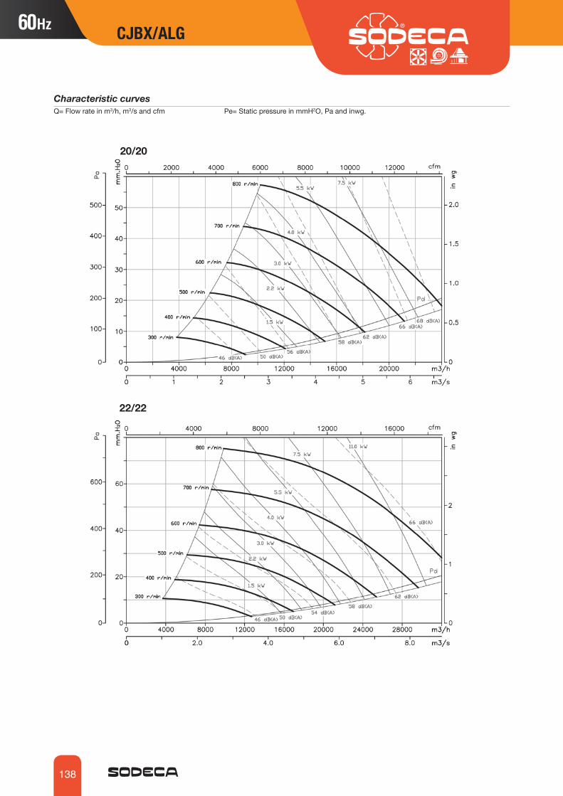
138
CJBX/ALG
Characteristic curves Q= Flow rate in m3/h, m3/s and cfm Pe= Static pressure in mmH2O, Pa and inwg.
20/20
22/22
CJBX/ALG

139
CJBX/ALG
Accessories
VIS TEJINT C2V AETRM VSD3/A-RFT
Characteristic curves Q= Flow rate in m3/h, m3/s and cfm Pe= Static pressure in mmH2O, Pa and inwg.
25/25
30/28

140
CDXR: Belt-driven double inlet centrifugal fans with shaft outlet on both sides and backward-curved impeller
CDXRT: Belt-driven double inlet centrifugal fans fitted with electric motors, a set of pulleys and belts, protectors and backward-curved impeller
CJDXR: Ventilation units with backward-curved impeller, acoustic insulation, fitted with fans from the CDXR series, resting on rubber shock-absorbers
Fan:• Galvanised sheet steel casing.• Backward-curved impeller blades made of galvanised sheet steel.• Galvanised sheet steel structure with thermal and acoustic insulation (CJDXR).• Cable gland for cable entry (CJDXR).
Motor:• IE3 efficiency motors for powers equal to or greater than
0.75kW except single-phase, 2-speed and 8-pole.• Class F motors with ball bearings and IP55 protection.• Multi voltage motor, special design valid for 220/380V
60Hz, 254/440V 60Hz, 265/460V 60Hz, 277/480V 60Hz.• Maximum temperature of air to be carried: -20 ºC. +60 ºC.
Finish:• Anti-corrosive finished galvanised sheet steel.
On request:• Different impulsion nozzle positions.• Special windings for different voltages.• With 2-speed motors.
Order code
CDXR 450
Impeller size mmCDXR: Belt-driven double inlet centrifugal fans with shaft outlet and backward-curved impeller
CDXRT 450 3
Impeller size mm
CDXRT: Belt-driven double inlet centrifugal fans fitted with electric motors, impeller with backward-curved blades
CJDXR: Ventilation units with a backward-curved impeller
Motor power (hp)
CDXRCDXRTCJDXR
CDXR
CDXRT CJDXR
CDXR-200 4900 2.2 3950 -20 85 10.0CDXR-250 4100 3.0 5500 -20 85 18.0CDXR-315 3200 4.0 10550 -20 85 32.6 CDXR-355 2800 5.5 13950 -20 85 42.7CDXR-400 2400 5.5 16000 -20 85 50.6CDXR-450 2200 7.5 20700 -20 85 67.5 CDXR-500 2000 11.0 27200 -20 85 84.2 CDXR-560 1800 15.0 34710 -20 85 142.0CDXR-630 1700 22.0 47000 -20 85 168.0CDXR-710 1400 22 53750 -20 85 223
Technical characteristicsMax.
speed(r/min)
Model Installed power(kW)
Maximum flow rate
(m3/h)
Approx. weight
(kg)
Air temperature (ºC) min. max.
60Hz 60Hz
CDXR CDXRT CJDXR CDXR CDXRT CJDXR

141
CDXR CDXRT CJDXR CDXR CDXRT CJDXR
Technical characteristics
CDXRT CJDXR 355-0.5 1085 1.84 1.06 0.37 5600 -20 +85 47.7 ACDXRT CJDXR 355-0.75 1230 2.28 1.31 0.55 6400 -20 +85 49.3 ACDXRT CJDXR 355-1 1360 3.10 1.79 0.75 7100 -20 +85 50.9 ACDXRT CJDXR 355-1.5 1540 4.03 2.32 1.10 8060 -20 +85 52.6 ACDXRT CJDXR 355-2 1700 5.96 3.44 1.50 8890 -20 +85 55.6 ACDXRT CJDXR 355-3 1930 8.36 4.83 2.20 10100 -20 +85 58.4 ACDXRT CJDXR 355-4 2180 10.96 6.33 3.00 11395 -20 +85 65.7 ACDXRT CJDXR 355-5.5 2400 14.10 8.12 4.00 12545 -20 +85 72.7 BCDXRT CJDXR 355-7.5 2670 11.60 5.50 13955 -20 +85 85.7 BCDXRT CJDXR 400-0.75 1010 2.28 1.31 0.55 7340 -20 +85 57.2 ACDXRT CJDXR 400-1 1130 3.10 1.79 0.75 8140 -20 +85 58.8 ACDXRT CJDXR 400-1.5 1290 4.03 2.32 1.10 9350 -20 +85 60.5 ACDXRT CJDXR 400-2 1420 5.96 3.44 1.50 10260 -20 +85 63.5 ACDXRT CJDXR 400-3 1620 8.36 4.83 2.20 11650 -20 +85 66.3 ACDXRT CJDXR 400-4 1820 10.96 6.33 3.00 13110 -20 +85 73.6 ACDXRT CJDXR 400-5.5 2000 14.10 8.12 4.00 14430 -20 +85 80.6 BCDXRT CJDXR 400-7.5 2230 11.60 5.50 16040 -20 +85 93.6 BCDXRT CJDXR 450-1 940 3.10 1.79 0.75 9500 -20 +85 75.7 ACDXRT CJDXR 450-1.5 1075 4.03 2.32 1.10 10750 -20 +85 77.4 ACDXRT CJDXR 450-2 1190 5.96 3.44 1.50 11960 -20 +85 80.4 ACDXRT CJDXR 450-3 1340 8.36 4.83 2.20 13600 -20 +85 83.2 ACDXRT CJDXR 450-4 1510 10.96 6.33 3.00 15100 -20 +85 90.5 ACDXRT CJDXR 450-5.5 1670 14.10 8.12 4.00 16835 -20 +85 97.5 BCDXRT CJDXR 450-7.5 1850 11.60 5.50 18500 -20 +85 110.5 BCDXRT CJDXR 450-10 2060 14.20 7.50 20760 -20 +85 120.5 BCDXRT CJDXR 500-1.5 880 4.03 2.32 1.10 12460 -20 +85 94.1 ACDXRT CJDXR 500-2 970 5.96 3.44 1.50 13815 -20 +85 97.1 ACDXRT CJDXR 500-3 1100 8.36 4.83 2.20 15700 -20 +85 99.9 ACDXRT CJDXR 500-4 1240 10.96 6.33 3.00 17650 -20 +85 107.2 ACDXRT CJDXR 500-5.5 1370 14.10 8.12 4.00 19430 -20 +85 114.2 BCDXRT CJDXR 500-7.5 1510 11.60 5.50 21600 -20 +85 127.2 BCDXRT CJDXR 500-10 1675 14.20 7.50 23950 -20 +85 137.2 BCDXRT CJDXR 500-15 1910 20.20 11.00 27220 -20 +85 156.2 BCDXRT CJDXR 560-2 810 5.96 3.44 1.50 15620 -20 +85 154.9 ACDXRT CJDXR 560-3 925 8.36 4.83 2.20 17830 -20 +85 157.7 ACDXRT CJDXR 560-4 1050 10.96 6.33 3.00 20380 -20 +85 165.0 ACDXRT CJDXR 560-5.5 1150 14.10 8.12 4.00 22170 -20 +85 172.0 BCDXRT CJDXR 560-7.5 1290 11.60 5.50 24940 -20 +85 185.0 BCDXRT CJDXR 560-10 1420 14.20 7.50 27658 -20 +85 195.0 BCDXRT CJDXR 560-15 1610 20.20 11.00 31050 -20 +85 214.0 BCDXRT CJDXR 560-20 1800 27.50 15.00 34710 -20 +85 227.0 BCDXRT CJDXR 630-3 740 8.36 4.83 2.20 21210 -20 +85 183.7 ACDXRT CJDXR 630-4 830 10.96 6.33 3.00 23860 -20 +85 191.0 ACDXRT CJDXR 630-5.5 920 14.10 8.12 4.00 26260 -20 +85 198.0 BCDXRT CJDXR 630-7.5 1020 11.60 5.50 29200 -20 +85 211.0 BCDXRT CJDXR 630-10 1135 14.20 7.50 32385 -20 +85 221.0 BCDXRT CJDXR 630-15 1285 20.20 11.00 36800 -20 +85 240.0 BCDXRT CJDXR 630-20 1450 27.50 15.00 41415 -20 +85 253.0 BCDXRT CJDXR 630-25 1550 35.00 18.50 44410 -20 +85 270.0 BCDXRT CJDXR 630-30 1640 42.00 22.00 47050 -20 +85 313.0 BCDXRT CJDXR 710-3 580 8.36 4.83 2.20 23200 -20 +85 238.7 ACDXRT CJDXR 710-4 655 10.96 6.33 3.00 26200 -20 +85 246.0 ACDXRT CJDXR 710-5.5 730 14.10 8.12 4.00 29200 -20 +85 253.0 BCDXRT CJDXR 710-7.5 805 11.60 5.50 32200 -20 +85 266.0 BCDXRT CJDXR 710-10 890 14.20 7.50 35600 -20 +85 276.0 BCDXRT CJDXR 710-15 1015 20.20 11.00 40600 -20 +85 295.0 BCDXRT CJDXR 710-20 1140 27.50 15.00 45600 -20 +85 308.0 BCDXRT CJDXR 710-25 1225 35.00 18.50 49000 -20 +85 325.0 BCDXRT CJDXR 710-30 1300 42.00 22.00 52000 -20 +85 368.0 B
Model Max.speed
Max. admissible current (A)
Installed power
Maximum flow rate
Air temperature (ºC)
Approx. weight
TypeAssembly
(r/min) 220-277V 380-480V (kW) (m3/h) min. max. (kg)

142
Dimensions mm
Model A B B1 B2 C E øe H K L N P Q V X x Y ZCDXRT-355-0.5 578 655 6 383 453 261 30 266 700 453 13x18 355 355 548 533 493 830 780CDXRT-355-0.75 578 655 6 383 453 261 30 266 700 453 13x18 355 355 548 533 493 850 780CDXRT-355-1 578 655 6 383 453 261 30 266 700 453 13x18 355 355 548 533 493 850 780CDXRT-355-1.5 578 655 6 383 453 261 30 266 700 453 13x18 355 355 548 533 493 870 780CDXRT-355-2 578 655 6 383 453 261 30 266 700 453 13x18 355 355 548 533 493 870 780CDXRT-355-3 578 655 6 383 453 261 30 266 700 453 13x18 355 355 548 533 493 885 780CDXRT-355-4 578 655 6 383 453 261 30 266 700 453 13x18 355 355 548 533 493 885 780CDXRT-400-0.75 651 736 4.5 431.5 507 290 30 300 760 507 13x18 355 355 613 587 547 925 840CDXRT-400-1 651 736 4.5 431.5 507 290 30 300 760 507 13x18 355 355 613 587 547 925 840CDXRT-400-1.5 651 736 4.5 431.5 507 290 30 300 760 507 13x18 355 355 613 587 547 940 840CDXRT-400-2 651 736 4.5 431.5 507 290 30 300 760 507 13x18 355 355 613 587 547 940 840CDXRT-400-3 651 736 4.5 431.5 507 290 30 300 760 507 13x18 355 355 613 587 547 956 840CDXRT-400-4 651 736 4.5 431.5 507 290 30 300 760 507 13x18 355 355 613 587 547 956 840CDXRT-450-1 728 827 5 486 569 322 35 336 845 569 13x18 530 530 681 649 609 1000 925CDXRT-450-1.5 728 827 5 486 569 322 35 336 845 569 13x18 530 530 681 649 609 1020 925CDXRT-450-2 728 827 5 486 569 322 35 336 845 569 13x18 530 530 681 649 609 1020 925CDXRT-450-3 728 827 5 486 569 322 35 336 845 569 13x18 530 530 681 649 609 1035 925CDXRT-450-4 728 827 5 486 569 322 35 336 845 569 13x18 530 530 681 649 609 1035 925CDXRT-500-1.5 800 918 5 538 638 352 35 375 915 638 13x18 530 530 750 718 678 1090 995CDXRT-500-2 800 918 5 538 638 352 35 375 915 638 13x18 530 530 750 718 678 1090 995CDXRT-500-3 800 918 5 538 638 352 35 375 915 638 13x18 530 530 750 718 678 1105 995CDXRT-500-4 800 918 5 538 638 352 35 375 915 638 13x18 530 530 750 718 678 1105 995CDXRT-560-2 893 1030 8 602 715 390 40 420 1000 715 13x18 530 530 845 815 765 1185 1080CDXRT-560-3 893 1030 8 602 715 390 40 420 1000 715 13x18 530 530 845 815 765 1205 1080CDXRT-560-4 893 1030 8 602 715 390 40 420 1000 715 13x18 530 530 845 815 765 1205 1080CDXRT-630-3 999 1157 7 678.5 801 434 45 471.5 1090 801 13x18 530 530 946 901 851 1310 1170CDXRT-630-4 999 1157 7 678.5 801 434 45 471.5 1090 801 13x18 530 530 946 901 851 1310 1170CDXRT-710-3 1121 1303 7 765 898 485 50 531 1255 898 17x22 630 630 1058 998 948 1435 1335CDXRT-710-4 1121 1303 7 765 898 485 50 531 1255 898 17x22 630 630 1058 998 948 1435 1335
CDXRTAssembly A
CDXR 200 - 250
A B B1 B2 C E øe H K L N P Q V X xCDXR-200 343 370 4 215 256 164 20 151 420 256 11x16 224 224 306 306 281
CDXR-250 419 461 4 270 322 195 20 187 490 322 11x16 224 224 384 372 347
CDXR-315 518 578 3 340 404 236 25 235 640 404 13x18 280 280 480 464 434
CDXR-355 578 655 6 383 453 261 30 266 700 453 13x18 355 355 548 533 493
CDXR-400 651 736 4.5 431.5 507 290 30 300 760 507 13x18 355 355 613 587 547
CDXR-450 728 827 5 486 569 322 35 336 845 569 13x18 530 530 681 649 609
CDXR-500 800 918 5 538 638 352 35 375 915 638 13x18 530 530 750 718 678
CDXR-560 893 1030 8 602 715 390 40 420 1000 715 13x18 530 530 845 815 765
CDXR-630 999 1157 7 678.5 801 434 45 471.5 1090 801 13x18 530 530 946 901 851
CDXR-710 1121 1303 7 765 898 485 50 531 1255 898 17x22 630 630 1058 998 948
CDXR 315...710
CDXR CDXRT CJDXR

143
CDXR CDXRT CJDXR
Dimensions mm
CJDXR
Assembly A Assembly B
CDXRTAssembly B
CDXR CDXRT CJDXR
CJDXR-355 1265 815 800 655 640 84.5 960 503.5 60 165 1020 454 -CJDXR-400 1370 900 900 740 743 82 1060 564 60 152 1120 508 -CJDXR-450 1480 990 1000 830 843 80.5 1160 623.5 60 152 1240 570 -CJDXR-500 1625 1080 1100 920 942 80 1260 680.5 60 152 1340 639 670CJDXR-560 1760 1195 1200 1035 1040 82.5 1360 851.5 60 165 1490 716 745CJDXR-630 1880 1322 1300 1162 1142 80 1460 841 60 152 1610 802 820CJDXR-710 2180 1500 1500 1340 1342 82 1660 968.5 80 168 1910 899 955
Model A B C D1 D2 E F G1 H I J L M
Model A B B2 C E øe H H1 K øO P V x XCDXRT-355-5.5 578 715 383 453 261 30 266 60 700 8 - 1110 493 533CDXRT-355-7.5 578 715 383 453 261 30 266 60 700 8 - 1110 493 533CDXRT-400-5.5 651 796 431.5 507 290 30 300 60 760 10 - 1210 547 587CDXRT-400-7.5 651 796 431.5 507 290 30 300 60 760 10 - 1210 547 587CDXRT-450-5.5 728 887 486 569 322 35 336 60 845 10 - 1330 609 649CDXRT-450-7.5 728 887 486 569 322 35 336 60 845 10 - 1330 609 649CDXRT-450-10 728 887 486 569 322 35 336 60 845 10 - 1330 609 649CDXRT-500-5.5 800 978 538 638 352 35 375 60 915 10 670 1430 678 718CDXRT-500-7.5 800 978 538 638 352 35 375 60 915 10 670 1430 678 718CDXRT-500-10 800 978 538 638 352 35 375 60 915 10 670 1430 678 718CDXRT-500-15 800 978 538 638 352 35 375 60 915 10 670 1430 678 718CDXRT-560-5.5 893 1090 602 715 390 40 420 60 1000 10 745 1580 765 815CDXRT-560-7.5 893 1090 602 715 390 40 420 60 1000 10 745 1580 765 815CDXRT-560-10 893 1090 602 715 390 40 420 60 1000 10 745 1580 765 815CDXRT-560-15 893 1090 602 715 390 40 420 60 1000 10 745 1580 765 815CDXRT-560-20 893 1090 602 715 390 40 420 60 1000 10 745 1580 765 815CDXRT-630-5.5 999 1217 678.5 801 434 45 471.5 60 1090 10 805 1700 851 901CDXRT-630-7.5 999 1217 678.5 801 434 45 471.5 60 1090 10 805 1700 851 901CDXRT-630-10 999 1217 678.5 801 434 45 471.5 60 1090 10 805 1700 851 901CDXRT-630-15 999 1217 678.5 801 434 45 471.5 60 1090 10 805 1700 851 901CDXRT-630-20 999 1217 678.5 801 434 45 471.5 60 1090 10 805 1700 851 901CDXRT-630-25 999 1217 678.5 801 434 45 471.5 60 1090 10 805 1700 851 901CDXRT-630-30 999 1217 678.5 801 434 45 471.5 60 1090 10 805 1700 851 901CDXRT-710-5.5 1121 1383 765 898 485 50 531 80 1255 10 955 2000 948 998CDXRT-710-7.5 1121 1383 765 898 485 50 531 80 1255 10 955 2000 948 998CDXRT-710-10 1121 1383 765 898 485 50 531 80 1255 10 955 2000 948 998CDXRT-710-15 1121 1383 765 898 485 50 531 80 1255 10 955 2000 948 998CDXRT-710-20 1121 1383 765 898 485 50 531 80 1255 10 955 2000 948 998CDXRT-710-25 1121 1383 765 898 485 50 531 80 1255 10 955 2000 948 998CDXRT-710-30 1121 1383 765 898 485 50 531 80 1255 10 955 2000 948 998

144
Characteristic curves Q= Flow rate in m3/h, m3/s and cfm Pe= Static pressure in mmH2O, Pa and inwg.
200
250
CDXR CDXRT CJDXR

145
Characteristic curves Q= Flow rate in m3/h, m3/s and cfm Pe= Static pressure in mmH2O, Pa and inwg.
315
355
CDXR CDXRT CJDXR CDXR CDXRT CJDXR
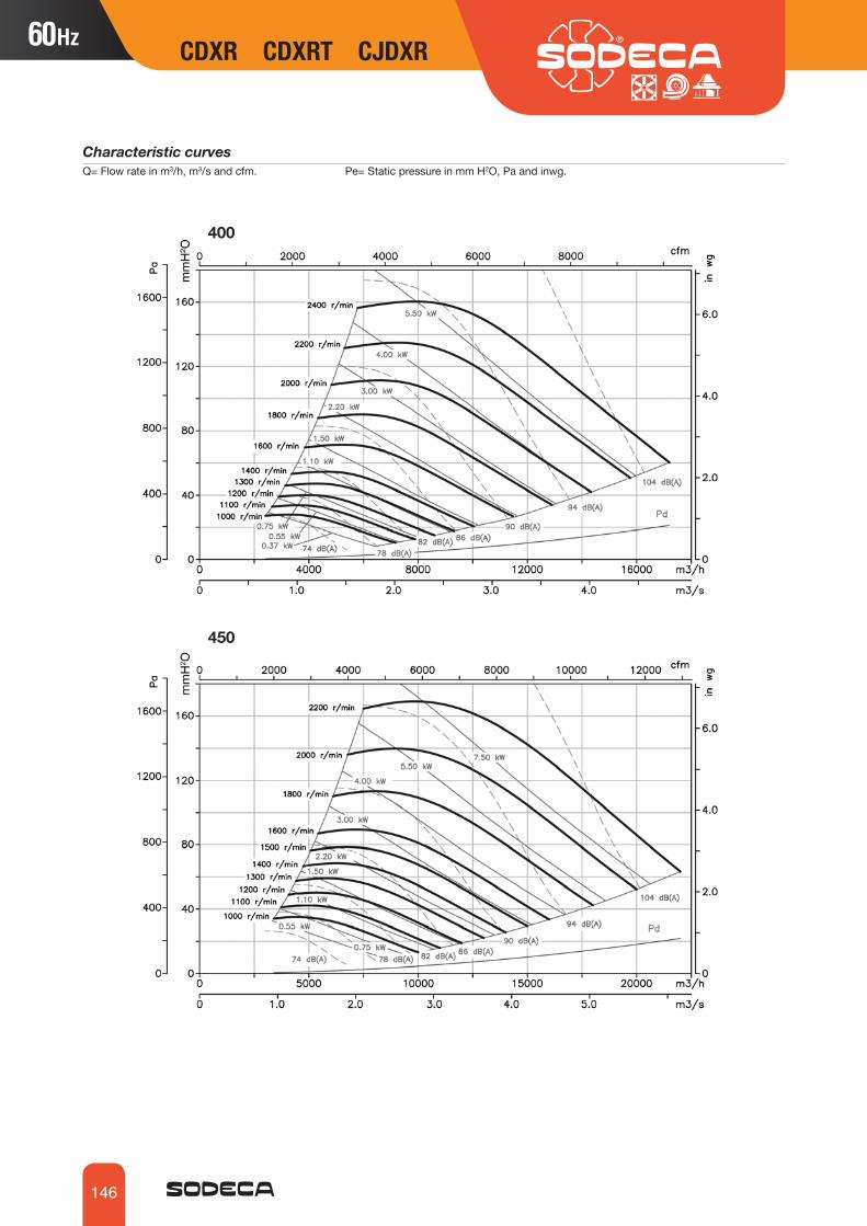
146
Characteristic curvesQ= Flow rate in m3/h, m3/s and cfm. Pe= Static pressure in mm H2O, Pa and inwg.
CDXR CDXRT CJDXR
400
450

147
CDXR CDXRT CJDXR CDXR CDXRT CJDXR
Characteristic curvesQ= Flow rate in m3/h, m3/s and cfm. Pe= Static pressure in mm H2O, Pa and inwg.
500
560

148
Characteristic curvesQ= Flow rate in m3/h, m3/s and cfm. Pe= Static pressure in mm H2O, Pa and inwg.
CDXR CDXRT CJDXR
Accessories
VIS TEJINT C2V AETRM VSD3/A-RFT
630
710

149
CDXR CDXRT CJDXR
CSXRCSXRTCJSXR
CSXR: Belt-driven single inlet centrifugal fans with shaft outlet and backward-curved impeller
CSXRT: Belt-driven single inlet centrifugal fans fitted with electric motors, a set of pulleys and belts, protectors and backward-curved impeller
CJSXR: Ventilation units with backward-curved impeller, acoustic insulation, fitted with fans from the CSXR series, resting on rubber shock-absorbers
Fan:• Galvanised sheet steel casing.• Backward-curved impeller blades made of galvanised sheet steel.• Galvanised sheet steel structure with thermal and acoustic insulation (CJSXR).• Cable gland for cable entry (CJSXR).
Motor:• IE3 efficiency motors for powers equal to or greater
than 0.75kW except single-phase, 2-speed and 8-pole.• Class F motors with ball bearings and IP55 protection.• Multi voltage motor, special design valid for 220/380V
60Hz, 254/440V 60Hz, 265/460V 60Hz, 277/480V 60Hz.• Maximum temperature of air to be carried: -20 ºC. +60 ºC.
Finish:• Anti-corrosive finished galvanised sheet steel.
On request:• Different impulsion nozzle positions.• Special windings for different voltages.• With 2-speed motors.
CSXR
CSXRT CJSXR
Order code
CSXR 400
Impeller size
CSXRT 500 4
Impeller size Motor power (hp)CSXRT: Single inlet, belt-driven centrifugal fans fitted with electric motors
CJSXR: Ventilation units with a backward-curved impeller
CSXR: Single inlet centrifugal fans with free shaft outlet
Technical characteristics
60Hz 60Hz
CSXR CSXRT CJSXR
CSXR-315 3200 1.50 4345 -20 +85 27CSXR-355 2800 2.20 5905 -20 +85 39CSXR-400 2400 3.00 7850 -20 +85 44CSXR-450 2200 4,00 10045 -20 +85 55CSXR-500 2200 5.50 12855 -20 +85 70CSXR-560 2000 7.50 17555 -20 +85 110CSXR-630 1600 7.50 18600 -20 +85 125CSXR-710 1400 7.50 23200 -20 +85 175CSXR-800 1600 22,00 39430 -20 +85 252CSXR-900 1400 30,00 46375 -20 +85 360CSXR-1000 1400 45,00 58225 -20 +85 445
Max.speed(r/min)
Model Max. installed power(kW)
Maximum flow rate
(m3/h)
Approx. weight
(kg)
MinimumAir temperature (ºC) min. max.

150
Technical characteristics
CSXR CSXRT CJSXR
CSXRT CJSXR 315-0.75 2520 2.4 1.4 0.55 4000 32 A BCSXRT CJSXR 315-1 2800 3.1 1.8 0.75 4500 34 A BCSXRT CJSXR 315-1.5 3250 4.4 2.5 1.1 5050 36 A BCSXRT CJSXR 355-0.75 2100 2.4 1.4 0.55 4750 41 A BCSXRT CJSXR 355-1 2300 3.1 1.8 0.75 5200 44 A BCSXRT CJSXR 355-1.5 2600 4.4 2.5 1.1 6000 46 A BCSXRT CJSXR 355-2 2875 5.8 3.4 1.5 6650 48 A BCSXRT CJSXR 400-0.75 1730 2.4 1.4 0.55 5600 49 A BCSXRT CJSXR 400-1 1900 3.3 1.9 0.75 6100 52 A BCSXRT CJSXR 400-1.5 2180 4.5 2.6 1.1 7000 54 A BCSXRT CJSXR 400-2 2400 5.8 3.4 1.5 7700 56 A BCSXRT CJSXR 450-0.75 1230 2.4 1.4 0.55 5800 61 A BCSXRT CJSXR 450-1 1380 3.3 1.9 0.75 6500 64 A BCSXRT CJSXR 450-1.5 1550 4.5 2.6 1.1 7500 66 A BCSXRT CJSXR 450-2 1700 6.0 3.5 1.5 8050 68 A BCSXRT CJSXR 450-3 1950 8.4 4.8 2.2 9050 72 A BCSXRT CJSXR 450-4 2200 10.4 6.0 3 10100 76 A BCSXRT CJSXR 500-1.5 1250 4.5 2.6 1.1 8200 88 A BCSXRT CJSXR 500-2 1380 6.0 3.5 1.5 9000 90 A BCSXRT CJSXR 500-3 1560 8.4 4.8 2.2 10200 93 A BCSXRT CJSXR 500-4 1730 11.3 6.5 3 11500 98 A BCSXRT CJSXR 500-5.5 1900 13.9 8.0 4 12500 107 A BCSXRT CJSXR 500-7.5 2130 - 11.1 5.5 14000 116 A BCSXRT CJSXR 560-2 1200 6.0 3.5 1.5 11000 100 A BCSXRT CJSXR 560-3 1380 8.4 4.8 2.2 12200 103 A BCSXRT CJSXR 560-4 1500 11.3 6.5 3 14000 108 A BCSXRT CJSXR 560-5.5 1670 13.9 8.0 4 15500 117 A BCSXRT CJSXR 560-7.5 1850 - 11.1 5.5 16200 122 A BCSXRT CJSXR 560-10 2050 - 14.8 7.5 18300 132 A BCSXRT CJSXR 630-3 1060 8.4 4.8 2.2 13200 119 A BCSXRT CJSXR 630-4 1150 11.3 6.5 3 14400 123 A BCSXRT CJSXR 630-5.5 1300 13.9 8.0 4 16000 132 A BCSXRT CJSXR 630-7.5 1450 - 11.1 5.5 18000 138 A BCSXRT CJSXR 630-10 1600 - 14.8 7.5 19800 147 A BCSXRT CJSXR 710-4 1000 11.3 6.5 3 17280 186 A BCSXRT CJSXR 710-5.5 1100 13.9 8.0 4 19080 195 A BCSXRT CJSXR 710-7.5 1200 - 11.1 5.5 20880 200 A BCSXRT CJSXR 710-10 1350 - 14.8 7.5 23760 210 A BCSXRT CJSXR 710-12.5 1480 - 17.5 9.2 25920 219 A BCSXRT 800-4 800 11.3 6.5 3 20800 226 BCSXRT 800-5.5 880 13.9 8.0 4 22680 234 BCSXRT 800-7.5 970 - 11.1 5.5 25100 240 BCSXRT 800-10 1070 - 14.8 7.5 27720 250 BCSXRT 800-12.5 1150 - 17.5 9.2 30000 259 BCSXRT 800-15 1230 - 22.0 11 32040 284 BCSXRT 800-20 1350 - 29.0 15 34000 305 BCSXRT 800-25 1450 - 36.5 18.5 37800 325 BCSXRT 800-30 1540 - 42.0 22 40000 344 BCSXRT 900-4 650 11.3 6.5 3 23760 281 BCSXRT 900-5.5 720 13.9 8.0 4 26000 289 BCSXRT 900-7.5 790 - 11.1 5.5 29500 295 BCSXRT 900-10 860 - 14.8 7.5 32100 305 BCSXRT 900-12.5 940 - 17.5 9.2 34200 314 BCSXRT 900-15 1020 - 22.0 11 37900 339 BCSXRT 900-20 1120 - 29.0 15 42000 360 BCSXRT 900-25 1190 - 36.5 18.5 43500 380 BCSXRT 900-30 1250 - 42.0 22 45500 399 BCSXRT 900-40 1400 - 59.0 30 51000 453 BCSXRT 1000-5.5 600 13.9 8.0 4 30500 342 BCSXRT 1000-7.5 660 - 11.1 5.5 33000 348 BCSXRT 1000-10 730 - 14.8 7.5 37000 358 BCSXRT 1000-12.5 790 - 17.5 9.2 40000 366 BCSXRT 1000-15 840 - 22.0 11 42500 392 BCSXRT 1000-20 940 - 29.0 15 46000 413 BCSXRT 1000-25 1000 - 36.5 18.5 50000 432 BCSXRT 1000-30 1060 - 42.0 22 52500 452 BCSXRT 1000-40 1160 - 59.0 30 59000 506 BCSXRT 1000-50 1260 - 68.0 37 64000 549 B
Model Max.speed
Max. admissible current (A)
Installed power
Maximum flow rate
Approx. weight
TypeAssembly
(r/min) 220-277V 380-480V (kW) (m3/h) (kg) CSXRT CJSXR

151
Dimensions mm
CSXR
Model A B B1 B2 C øD øe E F H K L N P Q V X x
CSXR-315 518 578 3 340 223 322 25 236 83 235 395 404 13x18 280 280 480 283 253
CSXR-355 578 655 6 383 247 362 30 261 78 266 425 453 13x18 355 355 548 327 287
CSXR-400 651 736 4.5 431.5 274 404 30 290 78 300 452 507 13x18 355 355 613 354 314
CSXR-450 726 827 5 486 308 448 35 322 92 336 500 569 13x18 530 530 681 388 348
CSXR-500 800 918 5 538 344 510 35 352 92 375 535 638 13x18 530 530 750 424 394
CSXR-560 893 1030 8 602 383 570 40 390 87 420 600 715 13x18 530 530 845 483 433
CSXR-630 999 1157 7 678.5 432 635 45 434 87 471.5 650 801 13x18 530 530 946 532 482
CSXR-710 1121 1303 7 765 478 722 50 485 115 531 725 898 17x22 630 630 1058 578 528
CSXR CSXRT CJSXR CSXR CSXRT CJSXR
Model A B C L øD H øe E F K X øO P V x1 x2
CSXR-800 1250 1615.5 533 1010 798 762 42 535 358.5 1291.5 1231.5 14 980 1050 515 614
CSXR-900 1408 1475 595 1130 898 850 48 604 407 1353.5 1293.5 14 1080 1150 515 676
CSXR-1000 1541 1966 663 1260 998 900 48 651 433 1529.5 1468.5 14 1180 1250 642 729.5

152
Dimensions mm
Model A B B1 B2 C øD øe E H H1 K L N P Q V X x
CSXRT-315-0.75 518 578 3 340 223 322 25 236 835 235 395 404 13x18 280 280 480 283 253
CSXRT-315-1 518 578 3 340 223 322 25 236 855 235 395 404 13x19 280 280 480 283 253
CSXRT-315-1.5 518 578 3 340 223 322 25 236 855 235 395 404 13x20 280 280 480 283 253
CSXRT-315-2 518 578 3 340 223 322 25 236 875 235 395 404 13x21 280 280 480 283 253
CSXRT-315-3 518 578 3 340 223 322 25 236 875 235 395 404 13x22 280 280 480 283 253
CSXRT-355-0.75 578 655 6 383 247 362 30 261 910 266 425 453 13x18 355 355 548 327 287
CSXRT-355-1 578 655 6 383 247 362 30 261 930 266 425 453 13x19 355 355 548 327 287
CSXRT-355-1.5 578 655 6 383 247 362 30 261 930 266 425 453 13x20 355 355 548 327 287
CSXRT-355-2 578 655 6 383 247 362 30 261 945 266 425 453 13x21 355 355 548 327 287
CSXRT-355-3 578 655 6 383 247 362 30 261 945 266 425 453 13x22 355 355 548 327 287
CSXRT-355-4 578 655 6 383 247 362 30 261 963 266 425 453 13x23 355 355 548 327 287
CSXRT-400-0.75 651 736 4.5 431.5 274 404 30 290 1012 300 452 507 13x18 355 355 613 354 314
CSXRT-400-1 651 736 4.5 431.5 274 404 30 290 1012 300 452 507 13x19 355 355 613 354 314
CSXRT-400-1.5 651 736 4.5 431.5 274 404 30 290 1012 300 452 507 13x20 355 355 613 354 314
CSXRT-400-2 651 736 4.5 431.5 274 404 30 290 1033 300 452 507 13x21 355 355 613 354 314
CSXRT-400-3 651 736 4.5 431.5 274 404 30 290 1033 300 452 507 13x22 355 355 613 354 314
CSXRT-400-4 651 736 4.5 431.5 274 404 30 290 1045 300 452 507 13x23 355 355 613 354 314
CSXRT-400-5.5 651 736 4.5 431.5 274 404 30 290 1072 300 452 507 13x24 355 355 613 354 314
CSXRT-450-0.75 726 827 5 486 308 448 35 322 1100 336 500 569 13x18 530 530 681 388 348
CSXRT-450-1 726 827 5 486 308 448 35 322 1100 336 500 569 13x19 530 530 681 388 348
CSXRT-450-1.5 726 827 5 486 308 448 35 322 1120 336 500 569 13x20 530 530 681 388 348
CSXRT-450-2 726 827 5 486 308 448 35 322 1120 336 500 569 13x21 530 530 681 388 348
CSXRT-450-3 726 827 5 486 308 448 35 322 1138 336 500 569 13x22 530 530 681 388 348
CSXRT-450-4 726 827 5 486 308 448 35 322 1138 336 500 569 13x23 530 530 681 388 348
CSXRT-450-5.5 726 827 5 486 308 448 35 322 1162 336 500 569 13x24 530 530 681 388 348
CSXRT-450-7.5 726 827 5 486 308 448 35 322 1205 336 500 569 13x25 530 530 681 388 348
CSXRT-450-10 726 827 5 486 308 448 35 322 1205 336 500 569 13x26 530 530 681 388 348
CSXRT-450-12.5 726 827 5 486 308 448 35 322 1205 336 500 569 13x27 530 530 681 388 348
CSXRT-500-1.5 800 918 5 538 344 510 35 352 1214 375 535 638 13x18 530 530 750 424 394
CSXRT-500-2 800 918 5 538 344 510 35 352 1214 375 535 638 13x19 530 530 750 424 394
CSXRT-500-3 800 918 5 538 344 510 35 352 1228 375 535 638 13x20 530 530 750 424 394
CSXRT-500-4 800 918 5 538 344 510 35 352 1228 375 535 638 13x21 530 530 750 424 394
CSXRT-500-5.5 800 918 5 538 344 510 35 352 1255 375 535 638 13x22 530 530 750 424 394
CSXRT-500-7.5 800 918 5 538 344 510 35 352 1292 375 535 638 13x23 530 530 750 424 394
CSXRT-500-10 800 918 5 538 344 510 35 352 1292 375 535 638 13x24 530 530 750 424 394
CSXRT-500-12’5 800 918 5 538 344 510 35 352 1292 375 535 638 13x25 530 530 750 424 394
CSXRT-500-15 800 918 5 538 344 510 35 352 1350 375 535 638 13x26 530 530 750 424 394
CSXRT-560-2 893 1030 8 602 383 570 40 390 1325 420 600 715 13x18 530 530 845 483 433
CSXRT
CSXR CSXRT CJSXR

153
Dimensions mm
CSXRT-560-3 893 1030 8 602 383 570 40 390 1340 420 600 715 13x19 530 530 845 483 433
CSXRT-560-4 893 1030 8 602 383 570 40 390 1340 420 600 715 13x20 530 530 845 483 433
CSXRT-560-5.5 893 1030 8 602 383 570 40 390 1365 420 600 715 13x21 530 530 845 483 433
CSXRT-560-7.5 893 1030 8 602 383 570 40 390 1410 420 600 715 13x22 530 530 845 483 433
CSXRT-560-10 893 1030 8 602 383 570 40 390 1410 420 600 715 13x23 530 530 845 483 433
CSXRT-560-12.5 893 1030 8 602 383 570 40 390 1410 420 600 715 13x24 530 530 845 483 433
CSXRT-560-15 893 1030 8 602 383 570 40 390 1464 420 600 715 13x25 530 530 845 483 433
CSXRT-630-3 999 1157 7 678.5 432 635 45 434 1470 471.5 650 801 13x18 530 530 946 532 482
CSXRT-630-4 999 1157 7 678.5 432 635 45 434 1470 471.5 650 801 13x19 530 530 946 532 482
CSXRT-630-5.5 999 1157 7 678.5 432 635 45 434 1492 471.5 650 801 13x20 530 530 946 532 482
CSXRT-630-7’5 999 1157 7 678.5 432 635 45 434 1531 471.5 650 801 13x21 530 530 946 532 482
CSXRT-630-10 999 1157 7 678.5 432 635 45 434 1531 471.5 650 801 13x22 530 530 946 532 482
CSXRT-630-12.5 999 1157 5 678.5 432 635 45 434 1531 471.5 650 801 13x23 530 530 946 532 482
CSXRT-630-15 999 1157 7 678.5 432 635 45 434 1590 471.5 650 801 13x24 530 530 946 532 482
CSXRT-630-20 999 1157 7 678.5 432 635 45 434 1590 471.5 650 801 13x25 530 530 946 532 482
CSXRT-710-4 1121 1303 7 765 478 722 50 485 1612 531 725 898 17x22 630 630 1058 578 528
CSXRT-710-5.5 1121 1303 7 765 478 722 50 485 1638 531 725 898 17x23 630 630 1058 578 528
CSXRT-710-7.5 1121 1303 7 765 478 722 50 485 1675 531 725 898 17x24 630 630 1058 578 528
CSXRT-710-10 1121 1303 7 765 478 722 50 485 1675 531 725 898 17x25 630 630 1058 578 528
CSXRT-710-12.5 1121 1303 7 765 478 722 50 485 1675 531 725 898 17x26 630 630 1058 578 528
CSXRT-710-15 1121 1303 7 765 478 722 50 485 1735 531 725 898 17x27 630 630 1058 578 528
CSXRT-710-20 1121 1303 7 765 478 722 50 485 1735 531 725 898 17x28 630 630 1058 578 528
CSXRT-710-25 1121 1303 7 765 478 722 50 485 1820 531 725 898 17x29 630 630 1058 578 528
CSXR CSXRT CJSXR CSXR CSXRT CJSXR
Model A B B1 B2 C øD øe E H H1 K L N P Q V X x
Model A B C L øD H E F K X øO P V x1 x2
CSXRT-800 1250 1615.5 533 1010 798 762 535 358.5 1321.5 1231.5 14 980 1050 515 614
CSXRT-900 1408 1475 595 1130 898 850 604 407 1383.5 1293.5 14 1080 1150 515 676
CSXRT-1000 1541 1966 663 1260 998 900 651 433 1559.5 1468.5 14 1180 1250 642 729.5
A B C D E F G H
CSXRT-800 1007 533 1063 589 268.5 250 281.5 13
CSXRT-900 1130 595 1186 651 280 300 312.5 13
CSXRT-1000 1267 663 1323 719 298.5 350 346.5 13
Impulsion flange accessory

154
Dimensions mm
Standard supply horizontal impulsion (H) RD 90 Horizontal impulsion on request (H) LG 90
CJSXR
Vertical impulsion on request (V) RD 0 Vertical impulsion on request (V) LG 0
CJSXR-315 1170 740 60 600 315 82 84.2 113 281 317.5 423.2 366.2 305 451.5 346.3 405 224 760 680 880 - 155CJSXR-355 1265 815 60 650 365 85 86.5 112.5 302.5 347.2 470.2 398 338 496 373 454 248 810 730 1020 - 152CJSXR-400 1370 900 60 680 400 82 90.2 111 331 386.2 522.2 447.2 359 543 407 508 275 840 760 1120 - 152CJSXR-450 1480 990 60 716 448 82 91.2 112.8 360 422.2 577.2 491 383 598 443 570 309 876 796 1240 - 152CJSXR-500 1625 1080 60 760 510 80.5 91 111.7 381.3 461.2 629.2 534.2 409 650 482 639 345 920 840 1340 670 152CJSXR-560 1760 1195 60 810 580 86.8 94.2 128 426 506.2 696.2 590 462 731 540 716 384 970 890 1490 745 152CJSXR-630 1880 1322 60 850 635 85.2 89.6 113.4 455.6 557.7 768.7 648.2 488 792.5 578.5 802 433 1010 930 820 1610 158CJSXR-710 2180 1500 80 910 710 103 108.2 100 491 632.2 873.2 737.2 562 865 624 899 479 1070 990 955 1910 168
Model A B B1 C ØD E E1 F F1 G1 G2 G3 H H1 H2 L K V V1 X X1 X2
CSXR CSXRT CJSXR

155
Characteristic curvesQ= Flow rate in m3/h, m3/s and cfm. Pe= Static pressure in mm H2O, Pa and inwg.
CSXR CSXRT CJSXR CSXR CSXRT CJSXR
315
355

156
Characteristic curvesQ= Flow rate in m3/h, m3/s and cfm. Pe= Static pressure in mm H2O, Pa and inwg.
CSXR CSXRT CJSXR
400
450

157
Characteristic curvesQ= Flow rate in m3/h, m3/s and cfm. Pe= Static pressure in mm H2O, Pa and inwg.
CSXR CSXRT CJSXR CSXR CSXRT CJSXR
500
560

158
Characteristic curvesQ= Flow rate in m3/h, m3/s and cfm. Pe= Static pressure in mm H2O, Pa and inwg.
CSXR CSXRT CJSXR
630
710

159
Characteristic curvesQ= Flow rate in m3/h, m3/s and cfm. Pe= Static pressure in mm H2O, Pa and inwg.
CSXR CSXRT CJSXR CSXR CSXRT CJSXR
800
900

160
Characteristic curvesQ= Flow rate in m3/h, m3/s and cfm. Pe= Static pressure in mm H2O, Pa and inwg.
Accessories
VIS TEJINT C2V AETRM VSD3/A-RFT
CSXR CSXRT CJSXR
1000

161
Technical characteristics
Max.speed(r/min)
Model Max. installed power(kW)
Maximum flow rate
(m3/h)
Air temperaturemin. max.
(ºC)
Approx. weight(kg)
TSA-12/6 1500 2.2 4800 -20 85 17.5TSA-15/7 1050 3 7400 -20 85 22.5TSA-18/9 920 4 10500 -20 85 33TSA-20/10 850 5.5 15000 -20 85 71TSA-22/11 1000 18.5 26000 -20 85 80TSA-25/13 810 18.5 32000 -20 85 93TSA-30/14 600 18.5 38000 -20 85 125
TSATSATCJTSA
TSA: Single inlet, belt-driven centrifugal fans with shaft outlet and forward-curved impeller
TSAT: Belt-driven, single inlet, centrifugal fans fitted with electric motors, a set of pulleys and belts, protectors and forward-curved impeller
CJTSA: Ventilation units with forward-curved impeller, acoustic insulation, fitted with fans from the TSA series, resting on rubber shock-absorbers
Fan:• Galvanised sheet steel casing.• Impeller with forward-curved reaction blades made of galvanised sheet steel.• Galvanised sheet steel structure with thermal and acoustic insulation (CJTSA).• Cable gland for cable entry (CJTSA).
Motor:• IE3 efficiency motors for powers equal to or greater than
0.75kW except single-phase, 2-speed and 8-pole.• Class F motors with ball bearings and IP55 protection.• Multi voltage motor, special design valid for 220/380V
60Hz, 254/440V 60Hz, 265/460V 60Hz, 277/480V 60Hz.• Maximum temperature of air to be carried: -20 ºC. +60 ºC.
Finish:• Anti-corrosive finished galvanised sheet steel.
On request:• Different impulsion nozzle positions.• Special windings for different voltages.• With 2-speed motors.
TSA
Order code
CJTSA 22/11 3
Impeller size in inches
Motor power (hp)
TSA 22/11
Impellersize
TSAT: Single inlet, belt-driven centrifugal fans fitted with electric motorsCJTSA: Ventilation units with a forward-curved impeller
TSA: Single inlet centrifugal fans with free shaft outlets
60Hz 60Hz
CSXR CSXRT CJSXR TSA TSAT CJTSA
TSAT CJTSA

162
Dimensions mm
TSA
Model A B B2 C øD E øe H K L M N O P Q V X x
TSA-12/6 498 532 290 210 325 230 25 242 435 345 75 90 9x17 324 324 468 270 242
TSA-15/7 583 632 348 269 400 265 25 284 494 404 75 90 9x17 406 406 553 329 301
TSA-18/9 694 756 415 301 475 323 25 341 526 482 75 90 9x17 520 608 664 361 333
Technical characteristics
TSA TSAT CJTSA
TSAT CJTSA 12/6-0.75 1000 2.4 1.4 0.55 2600 69 73TSAT CJTSA 12/6-1 1100 3.3 1.9 0.75 3100 71 74TSAT CJTSA 12/6-1.5 1250 4.5 2.6 1.1 3500 74 77TSAT CJTSA 12/6-2 1300 6.0 3.5 1.5 4250 77 80TSAT CJTSA 12/6-3 1500 8.3 4.8 2.2 4800 79 85TSAT CJTSA 15/7-1 800 3.3 1.9 0.75 4000 67 92TSAT CJTSA 15/7-1.5 850 4.5 2.6 1.1 4800 69 95TSAT CJTSA 15/7-2 920 6.0 3.5 1.5 5400 72 98TSAT CJTSA 15/7-3 1000 8.3 4.8 2.2 6400 75 103TSAT CJTSA 15/7-4 1050 11.2 6.5 3 7400 77 106TSAT CJTSA 18/9-1.5 750 4.5 2.6 1.1 5800 68 111TSAT CJTSA 18/9-2 790 6.0 3.5 1.5 6600 70 114TSAT CJTSA 18/9-3 800 8.3 4.8 2.2 8200 74 119TSAT CJTSA 18/9-4 850 11.2 6.5 3 9000 76 122TSAT CJTSA 18/9-5.5 920 14.9 8.6 4 10500 78 125TSAT CJTSA 20/10-2 650 6.0 3.5 1.5 8100 65 203TSAT CJTSA 20/10-3 690 8.3 4.8 2.2 10100 68 208TSAT CJTSA 20/10-4 750 11.2 6.5 3 11500 70 211TSAT CJTSA 20/10-5.5 790 14.9 8.6 4 13100 73 214TSAT CJTSA 20/10-7.5 850 11.1 5.5 15000 75 227TSAT CJTSA 22/11-3 580 8.3 4.8 2.2 11200 67 219TSAT CJTSA 22/11-4 610 11.2 6.5 3 13000 70 222TSAT CJTSA 22/11-5.5 650 14.9 8.6 4 15000 72 225TSAT CJTSA 22/11-7.5 690 11.1 5.5 17000 74 238TSAT CJTSA 22/11-10 750 14.8 7.5 19000 76 246TSAT CJTSA 22/11-12.5 790 17.8 9.2 21000 78 257TSAT CJTSA 22/11-15 830 21.5 11 22000 79 273TSAT CJTSA 22/11-20 910 28.5 15 24500 81 292TSAT CJTSA 22/11-25 1000 35.0 18.5 26000 83 322TSAT CJTSA 25/13-4 520 11.2 6.5 3 14000 62 254TSAT CJTSA 25/13-5.5 550 14.9 8.6 4 17000 65 257TSAT CJTSA 25/13-7.5 590 11.1 5.5 19500 67 270TSAT CJTSA 25/13-10 620 14.8 7.5 23000 70 278TSAT CJTSA 25/13-12.5 650 17.8 9.2 25000 72 289TSAT CJTSA 25/13-15 690 21.5 11 26500 74 305TSAT CJTSA 25/13-20 750 28.5 15 29500 75 324TSAT CJTSA 25/13-25 810 35.0 18.5 32000 77 354TSAT CJTSA 30/14-5.5 400 14.9 8.6 4 21000 69 331TSAT CJTSA 30/14-7.5 425 11.1 5.5 24000 72 344TSAT CJTSA 30/14-10 460 14.8 7.5 27500 74 352TSAT CJTSA 30/14-12.5 480 17.8 9.2 30000 76 363TSAT CJTSA 30/14-15 500 21.5 11 33000 77 379TSAT CJTSA 30/14-20 550 28.5 15 36500 78 398TSAT CJTSA 30/14-25 600 35.0 18.5 38000 81 428
Model Speed Max. admissible current (A)
Installed power
Maximum flow rate
Sound pres-sure level
Approx. weight
(r/min) 220-277V 380-480V (kW) (m3/h) dB(A) (kg)

163
TSAT
TSA
Dimensions mm
Model A B B1 B2 C øD E øe H K L M N O P Q V X x
TSA-20/10 843 963 35 523 330 575 375 35 440 620 603 100 110 9x17 646 811 798 410 370
TSA-22/11 913 1046 35 569 358 615 400 35 477 648 693 100 110 9x17 716 894 868 438 398
TSA-25/13 998 1161 35 642 412 695 423 35 519 701 793 100 110 9x17 801 1009 953 492 452
TSA-30/14 1206 1400 35 776 474 835 515 40 624 764 933 100 110 9x17 1009 1248 1161 554 514
Model A B B2 C øD E øe H H1 K K1 L M N O P Q V X x
TSAT-12/6-0.75 498 532 290 210 325 230 25 805 242 435 475 345 75 90 9x17 324 324 468 270 242
TSAT-12/6-1 498 532 290 210 325 230 25 805 242 435 475 345 75 90 9x17 324 324 468 270 242
TSAT-12/6-1.5 498 532 290 210 325 230 25 825 242 435 475 345 75 90 9x17 324 324 468 270 242
TSAT-12/6-2 498 532 290 210 325 230 25 825 242 435 475 345 75 90 9x17 324 324 468 270 242
TSAT-12/6-3 498 532 290 210 325 230 25 845 242 435 475 345 75 90 9x17 324 324 468 270 242
TSAT-15/7-1 583 632 348 269 400 265 25 905 284 494 535 404 75 90 9x17 406 406 553 329 301
TSAT-15/7-1.5 583 632 348 269 400 265 25 925 284 494 535 404 75 90 9x17 406 406 553 329 301
TSAT-15/7-2 583 632 348 269 400 265 25 925 284 494 535 404 75 90 9x17 406 406 553 329 301
TSAT-15/7-3 583 632 348 269 400 265 25 945 284 494 535 404 75 90 9x17 406 406 553 329 301
TSAT-15/7-4 583 632 348 269 400 265 25 945 284 494 535 404 75 90 9x17 406 406 553 329 301
TSAT-18/9-1.5 694 756 415 301 475 323 25 1050 341 526 566 482 75 90 9x17 520 608 664 361 333
TSAT-18/9-2 694 756 415 301 475 323 25 1050 341 526 566 482 75 90 9x17 520 608 664 361 333
TSAT-18/9-3 694 756 415 301 475 323 25 1070 341 526 566 482 75 90 9x17 520 608 664 361 333
TSAT-18/9-4 694 756 415 301 475 323 25 1070 341 526 566 482 75 90 9x17 520 608 664 361 333
TSAT-18/9-5.5 694 756 415 301 475 323 25 1095 341 526 566 482 75 90 9x17 520 608 664 361 333
TSA TSAT CJTSA TSA TSAT CJTSA

164
Dimensions mm
TSAT
Model A B B1 B2 C øD E øe H H1 K K1 L M N O P Q V X x
TSAT-20/10-2 843 963 35 523 330 575 375 35 1255 440 620 670 603 100 110 9x17 646 811 798 410 370
TSAT-20/10-3 843 963 35 523 330 575 375 35 1275 440 620 670 603 100 110 9x17 646 811 798 410 370
TSAT-20/10-4 843 963 35 523 330 575 375 35 1275 440 620 670 603 100 110 9x17 646 811 798 410 370
TSAT-20/10-5.5 843 963 35 523 330 575 375 35 1300 440 620 670 603 100 110 9x17 646 811 798 410 370
TSAT-20/10-7.5 843 963 35 523 330 575 375 35 1340 440 620 670 603 100 110 9x17 646 811 798 410 370
TSAT-22/11-3 913 1046 35 569 358 615 400 35 1355 477 648 700 693 100 110 9x17 716 894 868 438 398
TSAT-22/11-4 913 1046 35 569 358 615 400 35 1355 477 648 700 693 100 110 9x17 716 894 868 438 398
TSAT-22/11-5.5 913 1046 35 569 358 615 400 35 1280 477 648 700 693 100 110 9x17 716 894 868 438 398
TSAT-22/11-7.5 913 1046 35 569 358 615 400 35 1420 477 648 700 693 100 110 9x17 716 894 868 438 398
TSAT-22/11-10 913 1046 35 569 358 615 400 35 1420 477 648 700 693 100 110 9x17 716 894 868 438 398
TSAT-22/11-12.5 913 1046 35 569 358 615 400 35 1420 477 648 700 693 100 110 9x17 716 894 868 438 398
TSAT-22/11-15 913 1046 35 569 358 615 400 35 1480 477 648 700 693 100 110 9x17 716 894 868 438 398
TSAT-22/11-20 913 1046 35 569 358 615 400 35 1480 477 648 700 693 100 110 9x17 716 894 868 438 398
TSAT-22/11-25 913 1046 35 569 358 615 400 35 1565 477 648 700 693 100 110 9x17 716 894 868 438 398
TSAT-25/13-4 998 1161 35 642 412 695 423 35 1470 519 701 750 793 100 110 9x17 801 1009 953 492 452
TSAT-25/13-5.5 998 1161 35 642 412 695 423 35 1495 519 701 750 793 100 110 9x17 801 1009 953 492 452
TSAT-25/13-7.5 998 1161 35 642 412 695 423 35 1540 519 701 750 793 100 110 9x17 801 1009 953 492 452
TSAT-25/13-10 998 1161 35 642 412 695 423 35 1540 519 701 750 793 100 110 9x17 801 1009 953 492 452
TSAT-25/13-12.5 998 1161 35 642 412 695 423 35 1540 519 701 750 793 100 110 9x17 801 1009 953 492 452
TSAT-25/13-15 998 1161 35 642 412 695 423 35 1565 519 701 750 793 100 110 9x17 801 1009 953 492 452
TSAT-25/13-20 998 1161 35 642 412 695 423 35 1565 519 701 750 793 100 110 9x17 801 1009 953 492 452
TSAT-25/13-25 998 1161 35 642 412 695 423 35 1680 519 701 750 793 100 110 9x17 801 1009 953 492 452
TSAT-30/14-5.5 1206 1400 35 776 474 835 515 40 1735 624 764 815 933 100 110 9x17 1009 1248 1161 554 514
TSAT-30/14-7.5 1206 1400 35 776 474 835 515 40 1775 624 764 815 933 100 110 9x17 1009 1248 1161 554 514
TSAT-30/14-10 1206 1400 35 776 474 835 515 40 1775 624 764 815 933 100 110 9x17 1009 1248 1161 554 514
TSAT-30/14-12.5 1206 1400 35 776 474 835 515 40 1775 624 764 815 933 100 110 9x17 1009 1248 1161 554 514
TSAT-30/14-15 1206 1400 35 776 474 835 515 40 1835 624 764 815 933 100 110 9x17 1009 1248 1161 554 514
TSAT-30/14-20 1206 1400 35 776 474 835 515 40 1835 624 764 815 933 100 110 9x17 1009 1248 1161 554 514
TSAT-30/14-25 1206 1400 35 776 474 835 515 40 1925 624 764 815 933 100 110 9x17 1009 1248 1161 554 514
TSA TSAT CJTSA

165
CJTSA
Dimensions mm
Standard supply horizontal impulsion (H) RD-90
Horizontal impulsion on request (H) LG-90 Vertical impulsion on request (V) LG-0
Vertical impulsion on request (V) RD-0
Model A B C ØD E E F G1 G1 H L L KCJTSA-12/6-H 850 650 540 330 74 - - 288 - 288 346 - 210CJTSA-12/6-V 850 650 540 330 - - 30 318 - 328 346 - 210CJTSA-15/7-H 1000 755 600 400 74 - - 328 - 328 411 - 270CJTSA-15/7-V 1000 755 600 400 - - 30 378 - 383 411 - 270CJTSA-18/9-H 1200 875 620 480 74 - - 383 - 388 491 - 305CJTSA-18/9-V 1200 875 620 480 - - 30 433 - 448 491 - 305CJTSA-20/10-H 1485 1175 730 565 175 120 - 475 530 440 613 605 343CJTSA-20/10-V 1485 1175 730 565 - - 75 535 - 585 613 - 343CJTSA-22/11-H 1570 1250 760 615 165 110 - 510 565 470 708 700 373CJTSA-22/11-V 1570 1250 760 615 - - 75 570 - 640 708 - 373CJTSA-25/13-H 1610 1375 820 685 175 120 - 550 605 495 803 795 423CJTSA-25/13-V 1610 1375 820 685 - - 75 625 - 705 803 - 423CJTSA-30/14-H 1845 1600 855 820 160 95 - 655 710 580 943 935 488CJTSA-30/14-V 1845 1600 855 820 - - 75 760 - 825 943 - 488
with bench
with bench
with bench
TSA TSAT CJTSA TSA TSAT CJTSA
Characteristic curvesQ= Flow rate in m3/h, m3/s and cfm. Pe= Static pressure in mm H2O, Pa and inwg.
12/6
(mm
H2 O
)

166
Characteristic curvesQ= Flow rate in m3/h, m3/s and cfm. Pe= Static pressure in mm H2O, Pa and inwg.
15/7
TSA TSAT CJTSA
18/9
(mm
H2 O
)(m
mH
2 O)
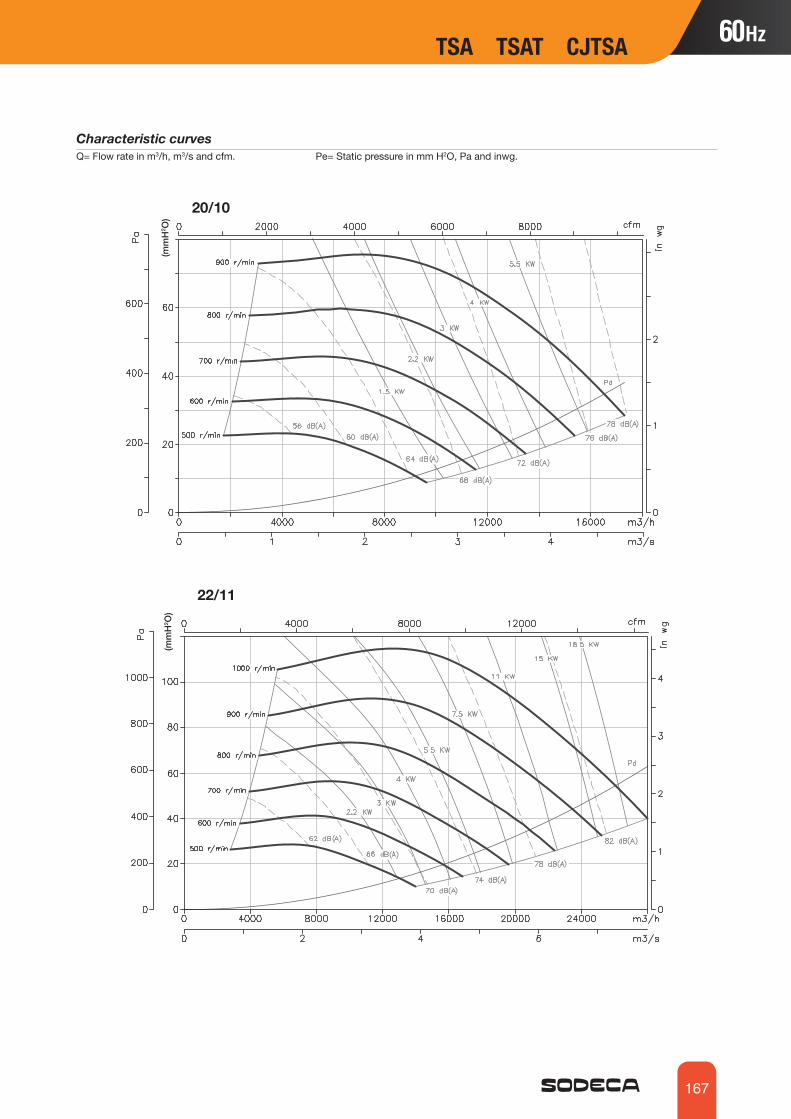
167
Characteristic curvesQ= Flow rate in m3/h, m3/s and cfm. Pe= Static pressure in mm H2O, Pa and inwg.
22/11
20/10
TSA TSAT CJTSA TSA TSAT CJTSA
(mm
H2 O
)(m
mH
2 O)

168
25/13
Characteristic curvesQ= Flow rate in m3/h, m3/s and cfm. Pe= Static pressure in mm H2O, Pa and inwg.
30/14
Accessories
VIS TEJINT C2V AETRM VSD3/A-RFT
TSA TSAT CJTSA
(mm
H2 O
)(m
mH
2 O)

169
Medium pressure, single inlet centrifugal fans with sheet steel casing and impellerCMP
Dynamically-balanced impellers with extremely robust cores
Fan:• Sheet steel casing.• Forward-curved impeller made of galvanised sheet steel.• CMP 38-2M model casing in cast aluminium.• Maximum temperature of air to be carried: -20 ºC + 120 ºC, maximum +100 ºC model
CMP-38.
Motor:• IE3 efficiency motors for powers equal to or
greater than 0.75kW except single-phase, 2-speed and 8-pole.
• Class F motors with ball bearings and IP55 protection except single-phase models, with IP54 protection CMP-38 model with IP21 protection.
• Multi voltage motor, special design valid for 220/380V 60Hz, 254/440V 60Hz, 265/460V 60Hz, 277/480V 60Hz.
Finish: • Anti-corrosive finish of polyester
resin polymerised at 190 ºC, previously degreased with phosphate-free nanotechnological treatment.
On request:• Special windings for different voltages.• Fan prepared for air transmission of up
to 250 ºC.• Stainless steel fan.• Category 2 ATEX certification
(see CMP/ATEX series).
Order code
CMP 1128 2T 5.5
Impeller sizeCMP: Medium pressure, single inlet centrifugal fans with sheet steel casing and impeller
Number of motor poles2=3500 r/min. 60 Hz4=1680 r/min. 60 Hz6=1080 r/min. 60 Hz
Motor power (hp)T= Three-phaseM=Single-phase
Technical characteristics
60Hz
TSA TSAT CJTSA CMP
CMP-38-2M/E 3180 0.54 0.01 135 50 2CMP-38-2M 3120 0.54 0.01 160 50 2CMP-512-2T 3420 0.55 0.32 0.08 490 62 4CMP-512-2M 3480 0.6 0.08 490 62 4CMP-512-4T 1728 0.55 0.32 0.05 255 55 3.5CMP-512-4M 1728 0.6 0.05 255 55 3.5CMP-514-2T 3420 1.21 0.7 0.18 800 65 5CMP-514-2M 3240 1.8 0.18 800 65 5CMP-514-4T 1728 0.55 0.32 0.08 565 58 4.5CMP-514-4M 1728 0.6 0.08 565 58 4.5CMP-616-2T 3288 1.73 1 0.55 1380 69 8CMP-616-2M 3312 2.95 0.55 1380 69 9.5CMP-616-4T 1680 0.65 0.37 0.1 850 61 7.5CMP-616-4M 1680 0.72 0.1 850 61 7.5CMP-620-2T 3288 1.73 1 0.37 765 68 9.5CMP-620-2M 3312 2.95 0.37 765 68 10CMP-620-4T 1650 0.69 0.4 0.1 810 61 7.5CMP-620-4M 1650 0.76 0.1 810 61 7.5CMP-718-2T 3426 3 1.73 0.75 1485 70 12.5CMP-718-2M 3300 5.2 0.75 1485 70 12.8
Model Speed Max. admissible current (A) Installed powerMaximum flow rate Sound pres-
sure level Approx. weight
(r/min) 220-277V 380-480V (kW) (m3/h) dB(A) (kg)

170
Technical characteristics
Acoustic characteristics
Sound power spectrum Lw(A) in dB(A) per Hz frequency band
Model 63 125 250 500 1000 2000 4000 8000 Modelo 63 125 250 500 1000 2000 4000 800038 25 35 46 53 57 54 52 45512-2 37 47 58 65 69 66 64 57512-4 30 40 51 58 62 59 57 50514-2 40 50 61 68 72 69 67 60514-4 33 43 54 61 65 62 60 53616-2 44 54 65 72 76 73 71 64616-4 36 46 57 64 68 65 63 56620-2 43 53 64 71 75 72 70 63620-4 36 46 57 64 68 65 63 56718-2 45 55 66 73 77 74 72 65718-4 38 48 59 66 70 67 65 58820-2 48 58 69 76 80 77 75 68820-4 41 51 62 69 73 70 68 61922-2-1.5 45 55 66 73 77 74 72 65922-2-2 46 56 67 74 78 75 73 66922-2-3 49 59 70 77 81 78 76 69922-4 41 51 62 69 73 70 68 611025-2-3 48 58 69 76 80 77 75 681025-2-4 52 62 73 80 84 81 79 721025-4 45 55 66 73 77 74 72 651128-2-4 52 62 73 80 84 81 79 721128-2-5.5 56 66 77 84 88 85 83 761128-4 49 59 70 77 81 78 76 69
1128-6 35 45 56 63 67 64 62 551231-4-3 51 60 71 78 82 80 78 711231-4-4 53 62 73 80 84 82 80 731231-4-5,5 55 64 75 82 86 84 82 751231-6 42 51 62 69 73 71 69 621435-4-4 54 63 74 81 85 83 81 741435-4-5.5 56 65 76 83 87 85 83 761435-4-7.5 58 67 78 85 89 87 85 781435-6 44 53 64 71 75 73 71 641640-4-5,5 55 64 75 82 86 84 82 751640-4-7,5 58 67 78 85 89 87 85 781640-4-10 60 69 80 87 91 89 87 801640-6 49 58 69 76 80 78 76 691845-4-7.5 61 71 82 89 93 91 89 811845-4-10 64 74 85 92 96 94 92 841845-6 56 66 77 84 88 86 84 762050-4-10 62 72 83 90 94 92 90 822050-4-12.5 64 74 85 92 96 94 92 842050-4-15 66 76 87 94 98 96 94 862050-4-20 68 78 89 96 100 98 96 882050-6 58 68 79 86 90 88 86 782563-6 67 77 88 95 99 96 94 87
CMP
CMP-718-4T 1692 1.32 0.76 0.25 1280 63 9.5CMP-718-4M 1692 1.4 0.25 1280 63 9.5CMP-820-2T 3414 4.16 2.4 1.1 1950 73 15CMP-820-2M 3420 7.1 1.1 1950 73 16CMP-820-4T 1620 1.32 0.76 0.25 1670 66 10CMP-820-4M 1680 2 0.25 1670 66 10CMP-922-2T-1.5 3414 4.16 2.4 1.1 1650 70 20CMP-922-2T-2 3432 5.63 3.25 1.5 2010 71 23CMP-922-2T-3 3456 7.97 4.6 2.2 2600 74 25.5CMP-922-4T 1674 2.51 1.45 0.55 2450 66 19CMP-1025-2T-3 3456 7.97 4.6 2.2 2100 73 28.5CMP-1025-2T-4 3474 10.57 6.1 3 2830 77 37.6CMP-1025-4T 1692 4.59 2.65 1.1 3400 70 38.5CMP-1128-2T-4 3474 10.57 6.1 3 2220 77 41.5CMP-1128-2T-5.5 3480 13.34 7.7 4 3210 81 47CMP-1128-4T 1704 8.49 4.9 2.2 5000 74 39CMP-1128-6T 1092 3.91 2.26 0.75 3300 60 28.5CMP-1231-4T-3 1704 8.49 4.9 2.2 4740 73 47CMP-1231-4T-4 1704 11.09 6.4 3 5910 75 49CMP-1231-4T-5.5 1728 14.38 8.3 4 6850 77 56CMP-1231-6T 1128 7.48 4.3 1.5 5115 64 49CMP-1435-4T-4 1704 11.09 6.4 3 5560 76 53CMP-1435-4T-5.5 1728 14.38 8.3 4 6260 78 61.5CMP-1435-4T-7.5 1746 11.4 5.5 7210 80 75.5CMP-1435-6T 1116 9.32 5.36 2.2 6400 66 58.5CMP-1640-4T-5.5 1728 14.38 8.3 4 7500 77 78.5CMP-1640-4T-7.5 1746 11.4 5.5 8035 80 92.5CMP-1640-4T-10 1746 15.1 7.5 9710 82 103.5CMP-1640-6T 1116 9.32 5.36 2.2 8100 71 75.5CMP-1845-4T-7.5 1746 11.4 5.5 8965 82 93.5CMP-1845-4T-10 1746 15.1 7.5 10350 85 104.5CMP-1845-6T 1116 9.32 5.36 2.2 8330 77 84CMP-2050-4T-10 1746 15.1 7.5 9000 83 134CMP-2050-4T-12.5 1740 17.8 9.2 10730 85 137CMP-2050-4T-15 1752 21.5 11 12525 87 153CMP-2050-4T-20 1746 28.5 15 19000 89 172CMP-2050-6T 1128 15.6 8.95 4 11000 79 146CMP-2563-6T 1164 31 15 21000 86 251
Model Speed Max. admissible current (A) Installed powerMaximum flow rate Sound pres-
sure level Approx. weight
(r/min) 220-277V 380-480V (kW) (m3/h) dB(A) (kg)

171
Dimensions mm
Intake nozzleImpulsion nozzle
Model A B1 B2 C C1 C2 øD1* ød1 ød2 E H1 I J J2 K k2 L øO
CMP-38-2M/E 141 165 97 122 96 26 80 85 2.4 60 60.5 100 80 46 50 77 52 8
CMP-38-2M 164.5 176.5 103.5 130 99 31 80 85 M4 79 64 95 107 82 53 72 67 6.5
Intake nozzleImpulsion nozzle
CMP-38
CMP-512...820
* Recommended nominal tube diameter
Model A B1 B2 C C1 C2 øD1* ød ød1 ød2 E H1 I J J1 J2 K k2 L øO
CMP-512-2T 185 206.5 118 251 212 39 112 140 132 M4 82.5 69 104 117 - 104.5 75 92 86 5.5
CMP-512-4T 185 206.5 118 249 210 39 112 140 132 M4 82.5 69 104 117 - 104.5 75 92 86 5.5
CMP-514-2T 225 254 150 281 236 45 140 169 151.5 M4 100 91 122 147 64 128 838 105 107 6.5
CMP-514-4T 225 254 150 261 216 45 140 169 151.5 M4 100 91 122 147 64 128 83 105 107 6.5
CMP-616-2T 258 297 173.5 320 264 56 160 204 180 M6 110 105.5 153 172 - 147 103 128 125 7
CMP-616-4T 258 297 173.5 283 227 56 160 204 180 M6 110 105.5 153 172 - 147 103 128 125 7
CMP-620-2T 298 347 202.5 321 265 56 200 247 230 M6 126 145.5 159 153 - 128 105 134 100 8
CMP-620-4T 298 347 202.5 283 227 56 200 247 230 M6 126 145.5 159 153 - 128 105 134 100 8
CMP-718-2T 303.5 348 201 355 294 61 180 238 210 M6 129.5 122 169 192 85 170 115 145 146 9
CMP-718-2M 303.5 348 201 355 245 61 180 238 210 M6 129.5 122 169 192 85 170 115 145 146 9
CMP-718-4T 303.5 348 201 331 270 61 180 238 210 M6 129.5 122 169 192 85 170 115 145 146 9
CMP-718-4M 303.5 348 201 331 270 61 180 238 210 M6 129.5 122 169 192 85 170 115 145 146 9
CMP-820-2T 322 377 223 369.5 301 68.5 200 247 230 M6 137.5 137 184 213 94.5 189 160 160 156 9
CMP-820-2M 322 377 223 369.5 301 68.5 200 247 230 M6 137.5 137 184 213 94.5 189 160 160 156 9
CMP-820-4T 322 377 223 345.5 277 68.5 200 247 230 M6 137.5 137 184 213 94.5 189 160 160 156 9
CMP-820-4M 322 377 223 345.5 277 68.5 200 247 230 M6 137.5 137 184 213 94.5 189 160 160 156 9
* Recommended nominal tube diameter
CMP CMP

172
Dimensions mm
Intake nozzleImpulsion nozzle
Intake nozzleImpulsion nozzle
CMP-922...1231
CMP-1435...2563
Model A B C C1 C2 øD1* ød ød1 ød2 E H H1 I J J1 K k2 L øO øO1 V v X X1 Y
CMP-922-2T-1.5 388.5 455 382.5 309 73.5 224 278 256 M8 180 280 134 204 282.5 128 140 180 215 9.5 10.5 290 220 114 50 105
CMP-922-2T-2 388.5 455 430.5 357 73.5 224 278 25 M8 180 280 134 204 282.5 128 140 180 215 9.5 10.5 290 220 114 50 105
CMP-922-2T-3 388.5 455 430.5 357 73.5 224 278 256 M8 180 280 134 204 282.5 128 140 180 215 9.5 10.5 290 220 114 50 105
CMP-922-4T 388.5 455 382.5 309 73.5 224 278 256 M8 180 280 134 204 282.5 128 140 180 215 9.5 10.5 290 220 114 50 105
CMP-1025-2T-3 427 503 456 370 86 250 305 282 M8 197 310 144 229 312.5 145 165 205 250 9.5 12.5 315 228 134 74 115.5
CMP-1025-2T-4 427 503 486 400 86 250 305 282 M8 197 310 144 229 312.5 145 165 205 250 9.5 12.5 315 228 134 74 115.5
CMP-1025-4T 427 503 456 370 86 250 305 282 M8 197 310 144 229 312.5 145 165 205 250 9.5 12.5 315 228 134 74 115.5
CMP-1128-2T-4 472 553 500.5 407 93.5 280 348 320 M8 216 340 152 244 364 170 180 220 296.5 9.5 12.5 348 245 144 95 122.5
CMP-1128-2T-5.5 472 553 523.5 430 93.5 280 348 320 M8 216 340 152 244 364 170 180 220 296.5 9.5 12.5 348 245 144 95 122.5
CMP-1128-4T 472 553 500.5 407 93.5 280 348 320 M8 216 340 152 244 364 170 180 220 296.5 9.5 12.5 348 245 144 95 122.5
CMP-1128-6T 472 553 470.5 377 93.5 280 348 320 M8 216 340 152 244 364 170 180 220 296.5 9.5 12.5 348 245 144 95 122.5
CMP-1231-4T-3 526 630 520.5 417 103.5 315 382 354 M8 238 390 179.5 264 382.5 180 200 240 320 11.5 13 382 322 183 140 126
CMP-1231-4T-4 526 630 520.5 417 103.5 315 382 354 M8 238 390 179.5 264 382.5 180 200 240 320 11.5 13 382 322 183 140 126
CMP-1231-4T-5.5 526 630 543.5 440 103.5 315 382 354 M8 238 390 179.5 264 382.5 180 200 240 320 11.5 13 382 322 183 140 126
CMP-1231-6T 526 630 520.5 417 103.5 315 382 354 M8 238 390 179.5 264 382.5 180 200 240 320 11.5 13 382 322 183 140 126
* Recommended nominal tube diameter
Model A B C C1 C2 øD1* ød ød1 ød2 E H H1 I J J1 K k1 L øO øO1 V v X X1 Y
CMP-1435-4T-4 573.5 715 549 431 118 355 422 394 M8 250 445 242.5 292 342.5 159 228 133 280 11.5 12 456 420 333 136.5 150
CMP-1435-4T-5.5 573.5 715 572 454 118 355 422 394 M8 250 445 242.5 292 342.5 159 228 133 280 11.5 12 456 420 333 136.5 150
CMP-1435-4T-7.5 573.5 715 610 492 118 355 422 394 M8 250 445 242.5 292 342.5 159 228 133 280 11.5 12 456 420 333 136.5 150
CMP-1435-6T 573.5 715 572 454 118 355 422 394 M8 250 445 242.5 292 342.5 159 228 133 280 11.5 12 456 420 333 136.5 150
CMP-1640-4T-5.5 634 799 596 465 130 400 464 438 M8 270 495 271 336 404 185 250 150 321 11.5 12 500 460 327 133.5 162.5
CMP-1640-4T-7.5 634 799 634 504 130 400 464 438 M8 270 495 271 336 404 185 250 150 321 11.5 12 500 460 327 133.5 162.5
CMP-1640-4T-10 634 799 634 504 130 400 464 438 M8 270 495 271 336 404 185 250 150 321 11.5 12 500 460 327 133.5 162.5
CMP-1640-6T 634 799 596 466 130 400 464 438 M8 270 495 271 336 404 185 250 150 321 11.5 12 500 460 327 133.5 162.5
CMP-1845-4T-7.5 711 901 668 521 147 450 515 485 M8 302 560 305 370 444 202 284 164 361 11.5 12 538 502 340 140 179.5
CMP-1845-4T-10 711 901 668 521 147 450 515 485 M8 302 560 305 370 444 202 284 164 361 11.5 12 538 502 340 140 179.5
CMP-1845-6T 711 901 630 483 147 450 515 485 M8 302 560 305 370 444 202 284 164 361 11.5 12 538 502 340 140 179.5
CMP-2050-4T-10 797 987 700.5 538 162.5 500 565 535 M10 345 610 313 411 544 250 315 182.5 451 11.5 12 653 615 435 188 196
CMP-2050-4T-12.5 797 987 752.5 590 162.5 500 565 535 M10 345 610 313 411 544 250 315 182.5 451 11.5 12 653 615 435 188 196
CMP-2050-4T-15 797 987 805.5 643 162.5 500 565 535 M10 345 610 313 411 544 250 315 182.5 451 11.5 12 653 615 435 188 196
CMP-2050-4T-20 797 987 805.5 643 162.5 500 565 535 M10 345 610 313 411 544 250 315 182.5 451 11.5 12 653 615 435 188 196
CMP-2050-6T 797 987 700.5 538 162.5 500 565 535 M10 345 610 313 411 544 250 315 182.5 451 11.5 12 653 615 435 188 196
CMP-2563-6T 1027 1213 1016 805 211 630 710 675 M10 460 742 378 512 706 330 410 230 600 17 14 590 540 450 200 239
* Recommended nominal tube diameter
CMP

173
Characteristic curvesQ= Flow rate in m3/h, m3/s and cfm. Pe= Static pressure in mm H2O, Pa and inwg.
CMP-38...820
2T/2M=3600 r/min
4T/4M=1800 r/min
CMP CMP

174
CMP-922...1231
2T=3600 r/min
Characteristic curvesQ= Flow rate in m3/h, m3/s and cfm. Pe= Static pressure in mm H2O, Pa and inwg.
4T=1500 r/min 6T=1200 r/min
CMP

175
Characteristic curvesQ= Flow rate in m3/h, m3/s and cfm. Pe= Static pressure in mm H2O, Pa and inwg.
4T=1800 r/min
4T=1800 r/min
CMP-1435...2563
CMP CMP

176
Characteristic curvesQ= Flow rate in m3/h, m3/s and cfm. Pe= Static pressure in mm H2O, Pa and inwg.
Accessories
RPA B BD BIC ACE S REG
OrientationStandard supply LG 270.Positions LG 180 and RD 180 on request with special anchoring measurements.
LG 45 LG 135 LG 225 LG 315
RD 45 RD 135 RD 225 RD 315
LG 0 LG 90 LG 180 LG 270
RD 0 RD 270RD 90 RD 180
INT C2V AETRM
6T=1200 r/min
VSD3/A-RFT
CMP

177
CMP
Extremely robust medium pressure, single inlet centrifugal fans fitted with a backward-curved impeller.CMRFan:• Sheet steel casing.• Impeller with reaction blades in extremely robust sheet steel.
Motor:• IE3 efficiency motors for powers equal to or
greater than 0.75kW except single-phase, 2-speed and 8-pole.
• Class F motors with ball bearings and IP55 protection.
• Multi voltage motor, special design valid for 220/380V 60Hz, 254/440V 60Hz, 265/460V 60Hz, 277/480V 60Hz.
• Maximum temperature of air to be carried: -20 ºC.+ 120 ºC.
Finish: • Anti-corrosive finish of polyester resin
polymerised at 190 ºC, previously degreased with phosphate-free nanotechnological treatment.
On request:• Special windings for different voltages.• Fan prepared for air transmission of up
to 250 ºC.• Stainless steel fan.• Category 2 ATEX certification
(see CMR/ATEX series).Extremely robust, high performance reaction impeller
Order code
CMR 1650 2T
Impeller size
CMR: Medium pressure, single inlet, centrifugal fans
Number of motor poles2=3500 r/min. 60 Hz4=1680 r/min. 60 Hz6=1080 r/min. 60 Hz8=900 r/min. 60 Hz
T= Three-phase
Technical characteristics
CMR
60Hz
CMR-1031-2T-3 3480 7.88 4.55 2.20 5950 80 44.3CMR-1135-2T-5.5 3480 13.51 7.80 4.00 7700 83 54.9CMR-1240-2T 3475 13.51 7.80 4.00 7650 86 93.5CMR-1240-4T 1745 3.22 1.86 0.75 5850 71 70.5CMR-1445-2T 3500 13.90 7.50 10800 87 126.0CMR-1445-4T 1750 5.89 3.40 1.50 8950 72 92.5CMR-1650-2T-15 3490 20.00 11.00 15950 89 178.0CMR-1650-4T-3 1730 8.49 4.90 2.20 11700 74 114.0CMR-1650-6T 1165 5.04 2.90 1.10 7850 64 114.0CMR-1856-4T-5.5 1745 14.38 8.30 4.00 15350 79 152.0CMR-1856-6T 1160 7.48 4.30 1.50 11100 70 146.5CMR-2063-4T 1750 11.40 5.50 19000 80 226.0CMR-2063-6T 1120 7.48 4.30 1.50 12300 71 208.5CMR-2063-8T 870 5.90 3.39 1.10 10550 65 210.5CMR-2271-4T 1760 21.50 11.00 30200 85 315.0CMR-2271-6T 1140 12.20 6.82 3.00 19600 76 293.5CMR-2271-8T 865 7.10 4.08 1.50 14300 69 275.5CMR-2380-4T 1680 41.00 22.00 48000 83 416.0CMR-2380-6T 1080 15.40 7.50 30000 75 363.0CMR-2380-8T 840 12.80 7.38 3.00 22000 66 317.0CMR-2590-4T 1770 68.00 37.00 54000 86 418.0CMR-2590-6T 1165 23.00 11.00 34000 76 378.0CMR-28100-4T 1770 98.00 55.00 75000 87 553.0CMR-28100-6T 1180 36.00 18.50 48000 77 521.0
Model Speed Max. admissible current (A) Installed powerMaximum flow rate Sound pres-
sure level Approx. weight
(r/min) 220-277V 380-480V (kW) (m3/h) dB(A) (kg)

178
Acoustic characteristics
Sound power spectrum Lw(A) in dB(A) per Hz frequency band.
Model 63 125 250 500 1000 2000 4000 8000 Model 63 125 250 500 1000 2000 4000 80001031-2 65 78 78 91 86 86 86 791135-2 72 79 77 89 87 93 92 791240-2 68 83 81 93 90 94 96 831240-4 56 70 76 79 79 80 70 591445-2 73 85 83 95 93 97 99 891445-4 59 72 78 83 80 83 78 641650-2 73 81 85 99 97 99 99 881650-4 64 74 82 84 83 85 76 661650-6 53 65 72 77 73 69 62 541856-4 69 78 91 87 90 91 85 711856-6 61 69 81 83 80 81 71 602063-4 80 85 91 93 91 88 81 73
2063-6 69 70 82 82 81 83 73 632063-8 64 70 77 76 77 74 66 572271-4 83 84 93 96 98 99 95 822271-6 73 73 87 86 90 90 79 682271-8 68 73 78 85 81 80 70 592380-4 76 78 94 91 96 97 93 822380-6 68 70 86 83 88 89 85 742380-8 59 61 77 74 79 80 76 652590-4 79 84 97 100 96 89 84 662590-6 70 79 89 88 85 84 74 6828100-4 82 89 101 102 97 93 87 7828100-6 73 82 91 90 88 86 77 70
The indicated values are determined by measuring the sound pressure level and sound power in dB(A) obtained in a free field at a distance equivalent to twice the size of the fan plus the impeller diameter, with a minimum of 1.5 m.
CMR
Intake nozzle
CMR-1031...2271
Dimensions mm
Model A B C øD1* ød ød1 ød2 E F G H I K k2 L M N øO1 P Q R
CMR-1031-2T 542 626 567 315 383 356 M8 250 292 245 381 320 250 285 315 276 35 11 472 556 17.5
CMR-1135-2T 600 696 583 355 425 398 M8 275 325 273 423 350 280 315 355 310 35 11 530 626 17.5
CMR-1240-2T 673 790 728 400 472 444 M10 305 368 310 480 395 315 355 400 358 40 11 593 710 20
CMR-1240-4T 673 790 590 400 472 444 M10 305 368 310 480 395 315 355 400 358 40 11 593 710 20
CMR-1445-2T 765 880 810 450 522 494 M10 350 415 339 541 445 355 405 450 404 45 11 675 790 20
CMR-1445-4T 765 880 649 450 522 494 M10 350 415 339 541 445 355 405 450 404 45 11 675 790 20
CMR-1650-2T 832 970 961 500 582 555 M10 375 457 378 592 490 400 450 500 445 45 13 742 880 20
CMR-1650-4T 832 970 715 500 582 555 M10 375 457 378 592 490 400 450 500 445 45 13 742 880 20
CMR-1650-6T 832 970 695 500 582 555 M10 375 457 378 592 490 400 450 500 445 45 13 742 880 20
CMR-1856-4T 925 1084 832 560 645 615 M10 415 510 426 658 550 450 500 560 493 50 13 825 984 25
CMR-1856-6T 925 1084 771 560 645 615 M10 415 510 426 658 550 450 500 560 493 50 13 825 984 25
CMR-2063-4T 1037 1218 973 630 720 688 M10 465 572 477 741 620 500 560 630 530 60 13 917 1098 30
CMR-2063-6T 1037 1218 893 630 720 688 M10 465 572 477 741 620 500 560 630 530 60 13 917 1098 30
CMR-2063-8T 1037 1218 893 630 720 688 M10 465 572 477 741 620 500 560 630 530 60 13 917 1098 30
CMR-2271-4T 1173 1375 1126 710 800 768 M12 525 648 538 837 690 560 625 710 603 65 13 1043 1245 32.5
CMR-2271-6T 1173 1375 1039 710 800 768 M12 525 648 538 837 690 560 625 710 603 65 13 1043 1245 32.5
CMR-2271-8T 1173 1375 1002 710 800 768 M12 525 648 538 837 690 560 625 710 603 65 13 1043 1245 32.5
* Recommended nominal tube diameter
CMR

179
CMR
CMR-2380...28100
Intake nozzleCMR-2380-4TCMR-2380-6TCMR-2380-8TCMR-2590-4TCMR-2590-6T
Intake nozzleCMR-28100-4TCMR-28100-6T
Model A B C C1 C2 øD1* ød ød1 ød2 E H H1 L øO1 V v X x x1 YCMR-2380-4T 1350 1660 1245 899 286 808 906 861 11.5 560 1000 500 800 17 930 870 1102.5 667.5 370 352.5
CMR-2380-6T 1350 1660 1030 744 286 808 906 861 11.5 56 1000 500 800 17 930 870 1102.5 667.5 370 352.5
CMR-2380-8T 1350 1660 1035 681 286 808 906 861 11.5 560 1000 500 800 17 930 870 1102.5 667.5 370 352.5
CMR-2590-4T 1495 1785 1390 1012 321 908 1008 958 14 630 1060 535 900 19 1030 970 1246 425 751 393
CMR-2590-6T 1495 1785 1235 857 321 908 1008 958 14 630 1060 535 900 19 1030 970 1121 340 721 373
CMR-28100-4T 1680 1990 1470 1051 362 1008 1108 1067 14 710 1180 610 1000 19 1130 1060 1378 460 843 454
CMR-28100-6T 1680 1990 1395 976 362 1008 1108 1067 14 710 1180 610 1000 19 1130 1060 1278 385 823 434
Dimensions mm
* Recommended nominal tube diameter
CMR-1031CMR-1135CMR-2590CMR-28100
CMR-1240CMR-1445CMR-1650
CMR-1856 CMR-2063 CMR-2271 CMR-2380Impulsion nozzle
CMR-1031 320 385 75 350 250 100 92.5 285 315 9 -CMR-1135 350 425 95 390 280 100 107.5 315 355 9 -CMR-1240 395 480 70 440 315 100 77.5 355 400 11 -CMR-1445 445 540 99 498 355 100 102.5 403 450 11 -CMR-1650 490 590 88 550 400 125 100 450 500 11 -CMR-1856 550 660 55 610 450 125 125 500 560 13 -CMR-2063 620 750 95 690 500 125 92.5 560 630 13 -CMR-2271 690 840 75 775 560 125 62.5 625 710 13 -CMR-2380 689 921 135.5 871 569 200 119.5 639 801 14 -CMR-2590 758 1018 84 968 638 200 54 708 898 18 -CMR-28100 835 1127 138.5 1077 715 200 92.5 785 1007 18 -
Model T J J1 J2 S s s1 s2 W Øz U

180
Characteristic curves Q= Flow rate in m3/h, m3/s and cfm. Pe= Static pressure in mm H2O, Pa and inwg.
CMR
2T=3600 r/min
4T=1800 r/min
4T=1800 r/min
6T=1200 r/min

181
CMR CMR
Characteristic curves Q= Flow rate in m3/h, m3/s and cfm. Pe= Static pressure in mm H2O, Pa and inwg.
OrientationStandard supply LG 270.Models 2380, 2590 and 28100 with LG 270 fixed orientation(other orientations only on request).
LG 0 LG 90 LG 270 RD 0 RD 90 RD 270LG 180 RD 180
Accessories
RPA B BD BIC ACE S REGINT C2V AETRM VSD3/A-RFT
6T=1200 r/min 8T=900 r/min

182
Medium pressure, single inlet centrifugal fans with cast aluminium casing and impellerCMAFan:• Cast aluminium casing.• Cast aluminium impeller.• Models 324, 325 and 426 impeller in polyamide, model 531-2T-3 impeller in sheet steel.
Motor:• IE3 efficiency motors for powers
equal to or greater than 0.75kW except single-phase, 2-speed and 8-pole.
• Class F motors with ball bearings and IP55 protection except single-phase models, with IP54 protection.
• Multi voltage motor, special design valid for 220/380V 60Hz, 254/440V 60Hz, 265/460V 60Hz, 277/480V 60Hz.
• Maximum temperature of air to be carried: -20 ºC + 120 ºC, maximum +70 ºC models with polyamide impeller.
Finish: • Anti-corrosive finish of polyester
resin polymerised at 190 ºC, previously degreased with phosphate-free nanotechnological treatment.
On request:• Special windings for different
voltages.• Cast aluminium impellers for
models 324, 325 and 426.• Fan prepared for air transmission
of up to 250 ºC.• Category 2 ATEX certification
(see CMA/ATEX series).Different impulsion position options
Order code
CMA 531 2T 1,5
Impeller sizeCMA: Medium pressure, single inlet centrifugal fans with cast aluminium casing and impeller
Number of motor poles2=3500 r/min. 60 Hz
Motor power (hp)T= Three-phaseM=Single-phase
Technical characteristicsSpeed(r/min)
Model Maximum admissible current (A)
220-277V 380-480V
Installed power(kW)
Maximum flow rate
(m3/h)
Sound pressure leveldB(A)
Approx. weight
(kg)CMA-218-2T 3504 0.61 0.35 0.09 265 63 6CMA-218-2M 3504 0.6 - 0.09 265 63 6CMA-324-2T 3420 1.21 0.7 0.18 440 70 9CMA-324-2M 3420 1.5 - 0.18 440 70 9CMA-325-2T 3336 1.64 0.95 0.25 600 73 11CMA-325-2M 3336 2.2 - 0.25 600 73 11CMA-426-2T 3318 1.78 1.03 0.37 850 75 13CMA-426-2M 3318 2.95 - 0.37 850 75 13CMA-527-2T 3360 2.42 1.4 0.55 1000 80 14.8CMA-527-2M 3360 3.9 - 0.55 1000 80 14.8CMA-528-2T-1 3336 3.12 1.8 0.75 1250 82 23.5CMA-528-2M-1 3336 5.2 - 0.75 1250 82 23.5CMA-528-2T-1.5 3420 4.42 2.55 1.1 1750 83 26CMA-528-2M-1.5 3420 7.1 - 1.1 1750 83 26CMA-531-2T-1.5 3456 4.42 2.55 1.1 1790 84 29CMA-531-2M-1.5 3456 7.1 - 1.1 1790 84 29CMA-531-2T-2 3420 5.89 3.4 1.5 2000 85 31CMA-531-2M-2 3420 9.3 - 1.5 2000 85 31CMA-531-2T-3 3360 8.23 4.75 2.2 2400 86 30CMA-540-2T 3468 5.89 3.4 1.5 2600 85 38CMA-545-2T-3 3408 8.23 4.75 2.2 2630 86 54CMA-545-2T-4 3456 10.91 6.3 3 3550 88 64
60Hz
CMA

183
Acoustic characteristicsSound power spectrum Lw(A) in dB(A) per Hz frequency band
Model 63 125 250 500 1000 2000 4000 8000 Modelo 63 125 250 500 1000 2000 4000 8000218 29 43 61 67 71 68 63 54324 36 50 68 74 78 75 70 61325 39 53 71 77 81 78 73 64426 41 55 73 79 83 80 75 66527 46 60 78 84 88 85 80 71528-1 48 62 80 86 90 87 82 73528-1.5 49 63 81 87 91 88 83 74
531-1.5 50 64 82 88 92 89 84 75531-2 51 65 83 89 93 90 85 76531-3 52 66 84 90 94 91 86 77540 54 67 85 91 96 92 87 79545-3 55 68 86 92 97 93 88 80545-4 57 70 88 94 99 95 90 82
Dimensions mm
Intake nozzle Impulsion nozzleCMA-218...531
Model A A1 B C C1 C2 øD ød ød1 ød2 E H H1 øI øK øk øO øO1 V v X x1 Y
CMA-218 241 236 288 239 208 32 80 113 90 M5 110 170 114.5 90 54 76 5.5 7 140 100 80 50 20
CMA-324 311 302 356 268 202 38 80 130 112 M5 145 205 145 108 62 90 7 9 173 125 90 60 20
CMA-325 335 328 399 271 223 40 94 140 122 M6 155 235 152 120 80 102 7 9 180 145 110 80 20
CMA-426 354 344 412 291 250 40 117 155 132 M6 162 240 163 140 90 119 7 13 210 160 105 65 26
CMA-527 371 361 440 295 254 42 125 170 147 M6 168 260 170 155 100 129 7 13 220 170 120 80 20
CMA-528...1 401 395 488 340 289 51 116 190 162 M6 178 290 177 190 130 160 11 13 230 180 140 100 20
CMA-528...1.5 401 395 488 337 289 48 135 190 162 M6 178 290 177 190 130 160 11 13 230 180 140 100 20
CMA-531...1.5 440 434 537 341 290 50 160 215 180 M6 193 320 200 200 140 175 11 13 240 190 160 120 21
CMA-531...2 440 434 537 388 340 50 160 215 180 M6 193 320 200 200 140 175 11 13 240 190 160 120 21
CMA-531...3 440 434 537 388 350 50 160 215 180 M6 193 320 200 200 140 175 11 13 240 190 160 120 21
Intake nozzle Impulsion nozzleCMA-540-545
Model A A1 B C C1 C2 øD ød ød1 ød2 E H H1 øI øK øk øO øO1 V v X x1 Y
CMA-540 567 580 695 375 320 80 170 240 205 M10 252 415 270 220 150 190 13 11 336 218 374 240 -
CMA-545…3 651 646 776 423 344 115 180 255 220 M10 290 450 309 250 175 220 13 13 336 238 392 292 -
CMA-545…4 651 646 776 497 344 115 180 255 220 M10 290 450 309 250 175 220 13 13 336 238 392 292 -
CMA CMA

184
Characteristic curvesQ= Flow rate in m3/h, m3/s and cfm. Pe= Static pressure in mm H2O, Pa and inwg.
Accessories
RPA B ACE S REG
OrientationStandard supply LG 270.LG 180 position on request and with special anchoring measurements.
LG 0 LG 90 LG 180 LG 270LG 45 LG 135 LG 315
INT C2V AETRM VSD3/A-RFT
CMA

185
CMA
Anti-corrosive finished, single inlet centrifugal fans made of polypropyleneCPV
Modern appearance and design
Fan:• Polypropylene casing.• Forward-curved impeller made of polypropylene.
Motor:• IE3 efficiency motors for powers equal to or greater than 0.75kW
except single-phase, 2-speed and 8-pole.• Class F motors with ball bearings and IP55 protection.• Multi voltage motor, special design valid for 220/380V 60Hz,
254/440V 60Hz, 265/460V 60Hz, 277/480V 60Hz.• Maximum temperature of air to be carried: -20 ºC +50 ºC.
Finish: • Anti-corrosive finished in plastic material.
On request:• Special windings for different voltages.• ATEX-certified Category 3.
Order code
CPV 1942 4T 10
Impeller sizeCPV: Anti-corrosive finished, single inlet centrifugal fans made of polypropylene
Number of motor poles2=3500 r/min. 60 Hz4=1680 r/min. 60 Hz6=1080 r/min. 60 Hz8=900 r/min. 60 Hz
Motorpower (hp)
T= Three-phase
Technical characteristics
*Only LG admit position
60Hz
CPV
CPV-815-2T 3372 1.73 1 0.37 950 75 14CPV-815-4T 1632 1.32 0.76 0.25 450 58 14CPV-1020-2T 3360 3 1.73 0.75 2000 81 19.5CPV-1020-4T 1632 1.32 0.76 0.25 1250 65 19.5CPV-1020-6T 1056 1.67 0.96 0.25 750 53 19.5CPV-1325-2T 3420 7.97 4.6 2.2 3250 87 27CPV-1325-4T 1632 1.78 1.03 0.37 2300 69 27CPV-1325-6T 1056 1.67 0.96 0.25 1400 59 27CPV-1630-4T 1704 5.98 3.45 1.5 4500 75 34.5CPV-1630-6T 1092 2.8 1.61 0.55 2700 63 34.5CPV-1840-4T 1704 11.09 6.4 3 6000 70 48CPV-1840-6T 1080 5.04 2.9 1.1 4200 65 42*CPV-1942-4T-7.5 1740 11.4 5.5 8500 79 66*CPV-1942-4T-10 1740 15.1 7.5 10500 84 77*CPV-1942-6T 1116 9.32 5.36 2.2 7000 75 49*CPV-1942-8T 852 7.1 4.08 1.5 5500 70 56CPV-2045-4T 1740 15.1 7.5 10400 78 102CPV-2045-6T 1140 12.2 7 3 7000 72 88CPV-1335-2T 3498 14.7 5.5 4700 84 91CPV-1160-4T 1752 21.5 11 8000 83 243CPV-2060-4T 1752 21.5 11 12000 81 245CPV-2160-4T 1746 28.5 15 15500 77 282*CPV-720-2T 3408 1.82 1.05 0.37 525 75 10*CPV-825-2T 3420 4.33 2.5 1.1 1140 79 17*CPV-930-2T 3456 7.57 4.37 2.2 1750 84 24
Model Speed Max. admissible current (A)
Installed power
Maximum flow rate
Sound pres-sure level
Approx. weight
(r/min) 220-277V 380-480V (kW) (m3/h) dB(A) (kg)

186
Acoustic characteristicsSound power spectrum Lw(A) in dB(A) per Hz frequency band
Model 63 125 250 500 1000 2000 4000 8000 Modelo 63 125 250 500 1000 2000 4000 8000815-2 56 69 77 81 81 77 73 65815-4 39 52 60 64 64 60 56 481020-2 62 75 83 87 87 83 79 711020-4 46 59 67 71 71 67 63 551020-6 34 47 55 59 59 55 51 431325-2 70 83 91 95 96 92 88 791325-4 52 65 73 77 78 74 70 611325-6 42 55 63 67 68 64 60 511630-4 60 73 81 85 86 82 78 691630-6 48 61 69 73 74 70 66 571840-4 55 68 76 80 81 77 73 641840-6 50 63 71 75 76 72 68 591942-4-7.5 75 85 87 90 89 89 87 78
1942-4-10 80 90 92 95 94 94 92 831942-6 71 81 83 86 85 85 83 741942-8 66 76 78 81 80 80 78 692045-4 63 76 84 88 89 85 81 722045-6 57 70 78 82 83 79 75 661335 67 80 88 92 93 89 85 761160 68 81 89 93 94 90 86 772060 66 79 87 91 92 88 84 752160 64 77 85 89 89 85 81 73720 56 69 77 81 81 77 73 65825 60 73 81 85 85 81 77 69930 65 78 86 90 90 86 82 74
Dimensions mm
CPV
CPV-720...1942
Model Fig. A A1 B C C1 C2 c øD E H H1 øK øO1 V v X x1 Y
CPV-720 1 375 - 486 350 80 270 45 90 212 311 130 90 6 340 320 180 160 92
CPV-815 1 307 335 521 360 100 260 30 125 100 281 177.5 125 8 355 335 180 160 90
CPV-825 1 445 - 552 433 110 323 55 125 218 320 170 125 6 340 320 180 160 103
CPV-930 1 540 - 678 477 100 377 40 160 262 390 205 160 6 420 400 240 160 137
CPV-1020-2T 1 340 397 593 445.5 116 329.5 32 160 100 290 223 160 8 355 335 180 160 127.5
CPV-1020-4/6T 1 340 397 584 422.5 116 306.5 32 160 100 281 223 160 8 355 335 180 160 122.5
CPV-1325-2T 1 413 505 735 494 130 364 35 200 103 370 265 200 8 400 380 180 160 125
CPV-1325-4/6T 1 413 505 716 432.5 130 302.5 35 200 103 351 265 200 8 400 380 180 160 113.5
CPV-1630-4T 1 480 602 890 536,5 145 391.5 35 250 117 440 323 250 8 450 430 240 220 142.5
CPV-1630-6T 1 480 602 880 503 145 358 35 250 117 430 323 250 8 450 430 240 220 138
CPV-1942-4T 1 580 750 1170 730,5 210 520.5 60 315 130 600 412.5 315 8 600 564 350 314 181.5
CPV-1942-6/8T 1 580 750 1150 679.5 210 469.5 60 315 130 580 412.5 315 8 600 564 350 314 204
CPV-1030...2045
Model Fig. A B C C1 C2 øD E H H1 I J J2 øK k k2 L øO øO1 V v X x1 x2 Y
CPV-1335 2 566 788 - 175 - 225 255 452 246 240 256 226 160 100 210 180 9 12 320 285 - 200 50 140
CPV-1840-4T 2 628 819 660 210 450 355 275 420 259 305 356 326 225 100 275 280 9 12 320 285 300 200 50 170
CPV-1840-6T 2 628 809 630 210 420 355 275 410 259 305 356 326 225 100 275 280 9 12 320 285 300 200 50 170
CPV-2045 2 724 1020 810 245 565 400 300 542 310 362 421 381 270 100 322 335 9 12 350 315 350 250 50 197

187
Dimensions mm
Characteristic curvesQ= Flow rate in m3/h, m3/s and cfm. Pe= Static pressure in mm H2O, Pa and inwg.
2T=3000 r/min. 4T=1500 r/min.
CPV CPV
CPV-1160...2160
Model Fig. A B C C1 C2 øD E H H1 I J J2 øK k k2 L øO øO1 V V1 v v1 X x x1 x2 Y
CPV-1160 3 937 1276 - 210 - 355 410 720 421 275 416 366 155 100 225 310 9 14 500 790 450 670 710 265 360 60 155
CPV-2060 3 937 1276 - 270 - 400 410 720 421 395 416 366 275 100 345 310 9 14 500 790 450 670 855 410 360 60 215
CPV-2160 3 981 1336 - 285 - 600 414 720 438.5 455 501 451 335 100 405 395 9 14 500 790 450 670 915 470 360 60 240

188
Characteristic curvesQ= Flow rate in m3/h, m3/s and cfm. Pe= Static pressure in mm H2O, Pa and inwg.
4T=1500 r/min. 6T=1000 r/min. 8T=750 r/min
2T=3000 r/min. 4T=1500 r/min
CPV

189
Accessories
Characteristic curvesQ= Flow rate in m3/h, m3/s and cfm. Pe= Static pressure in mm H2O, Pa and inwg.
LG 45 LG 315LG 0 LG 90 RD 45 RD 315RD 0 RD 90
OrientationStandard supply LG 90.
2T=3000 r/min.
BICINT C2V AETRM VSD3/A-RFT
CPV CPV

190
High pressure, single inlet centrifugal fans with cast aluminium casing and impellerCAFan:• Cast aluminium casing.• Cast aluminium impeller.
Motor:• IE3 efficiency motors for powers equal to or
greater than 0.75kW except single-phase, 2-speed and 8-pole.
• Class F motors with ball bearings and IP55 protection.
• Multi voltage motor, special design valid for 220/380V 60Hz, 254/440V 60Hz, 265/460V 60Hz, 277/480V 60Hz.
• Maximum temperature of air to be carried: -20 ºC.+ 120 ºC.
Finish: • Anti-corrosive finish of polyester resin
polymerised at 190 ºC, previously degreased with phosphate-free nanotechnological treatment.
On request:• Special windings for different voltages.• Fan prepared for air transmission of up
to 250 ºC.• ATEX-certified Category 2.
Order code
CA 148 2T 0,75
Impeller sizeCA: High pressure, single inlet centrifugal fans with cast aluminium casing and impeller
Number of motor poles2=3500 r/min. 60 Hz
Motor power (hp)T= Three-phase
Technical characteristics
Extremely thick aluminium construction to absorb noise and vibrations
60Hz
CA
CA-234-2T 3444 1.92 1.11 0.37 220 72 10.2CA-234-2M 3444 2.53 0.37 220 72 10.2CA-142-2T-0.33 3282 1.29 0.75 0.25 275 73 22.5CA-142-2T-0.5 3372 1.92 1.11 0.37 350 73 22.5CA-148-2T-0.75 3396 2.57 1.49 0.55 400 74 28.0CA-148-2T-1 3408 2.78 1.60 0.75 490 75 30.0CA-148-2T-1.5 3420 4.20 2.40 1.10 610 76 32.0CA-154-2T-1.5 3396 4.20 2.40 1.10 600 78 46.0CA-154-2T-2 3432 5.44 3.13 1.50 800 79 48.5CA-154-2T-3 3450 7.77 4.47 2.20 1280 80 50.5CA-160-2T-2 3420 5.44 3.13 1.50 500 83 57.0CA-160-2T-3 3432 7.77 4.47 2.20 900 84 58.0CA-166-2T-3 3444 7.77 4.47 2.20 500 84 67.0CA-166-2T-4 3444 10.18 5.88 3.00 950 85 73.0CA-166-2T-5.5 3432 13.60 7.82 4.00 1600 86 76.0CA-172-2T-5.5 3456 13.60 7.82 4.00 1100 87 90.0CA-172-2T-7.5 3456 10.50 5.50 1710 88 112.0CA-172-2T-10 3516 14.50 7.50 2300 89 124.0
Model Speed Max. admissible current (A) Installed powerMaximum flow rate Sound pres-
sure level Approx. weight
(r/min) 220-277V 380-480V (kW) (m3/h) dB(A) (kg)

191
Acoustic characteristicsSound power spectrum Lw(A) in dB(A) per Hz frequency band
Model 63 125 250 500 1000 2000 4000 8000 Model 63 125 250 500 1000 2000 4000 8000234 38 51 65 72 80 79 73 64142 39 52 66 73 81 80 74 65148-0.75 43 56 70 77 85 83 77 69148-1 44 57 71 78 86 84 78 70148-1.5 45 58 72 79 87 85 79 71154-1.5 47 60 74 81 89 87 81 73154-2 48 61 75 82 90 88 82 74154-3 49 62 76 83 91 89 83 75
160-2 54 67 81 88 96 94 88 80160-3 55 68 82 89 97 95 89 81166-3 55 68 82 89 97 95 89 81166-4 56 69 83 90 98 96 90 82166-5.5 57 70 84 91 99 97 91 83172-5.5 59 72 86 93 101 100 94 85172-7.5 60 73 87 94 102 101 95 86172-10 61 74 88 95 103 102 96 87
Dimensions mm
Model A A1 B C C1 C2 øD ød ød1 ød2 E H H1 øI øK øk øO øO1 V v x1 YCA-142-2T-0.33 494 488 540 270 221.52 48.5 90 160 130 M8 240 301 235 120 60 90 11 12 300 270 130 51CA-142-2T-0.5 494 488 540 290 241.5 48.5 90 160 130 M8 240 301 235 120 60 90 11 12 300 270 130 51CA-142-2T-0.75 563 557.5 639 308.5 251.5 57 100 170 140 M8 270 360 269.5 150 73 110 11 12 330 290 140 60CA-148-2T-1 563 557.5 639 324.5 267.5 57 100 170 140 M8 270 360 269.5 150 73 110 11 12 330 290 140 60CA-148-2T-1.5 563 557.5 639 324.5 267.5 57 100 170 140 M8 270 360 269.5 150 73 110 11 12 330 290 140 60CA-154-2T-1.5 630 625 708 348 268.5 79.5 115 183 155 M10 300 395 308 160 80 120 13 12 356 320 210 62CA-154-2T-2 630 625 708 371 291.5 79.5 115 183 155 M10 300 395 308 160 80 120 13 12 356 320 210 62CA-154-2T-3 630 625 708 396 316.5 79.5 115 183 155 M10 300 395 308 160 80 120 13 12 356 320 210 62CA-160-2T-2 708 699 785 381 291 90 130 230 192 M10 336 440 338 160 85 120 13 12 373 322 220 62CA-160-2T-3 708 699 785 406 316 90 130 230 192 M10 336 440 338 160 85 120 13 12 373 322 220 62CA-166-2T-3 759 752 866 399 319.5 79.5 140 230 200 M10 364 490 372 160 85 120 13 12 450 400 245 70CA-166-2T-4 759 752 866 423 343.5 79.5 140 230 200 M10 364 490 372 160 85 120 13 12 450 400 245 70CA-166-2T-5.5 759 752 866 445 365.5 79.5 140 230 200 M10 364 490 372 160 85 120 13 12 450 400 265 70CA-172-2T-5.5 818 813 923 451 371 80 148 230 200 M10 390 516 404 175 90 140 13 12 450 400 260 78CA-172-2T-7.5 818 813 923 492 412 80 148 230 200 M10 390 516 404 175 90 140 13 12 450 400 300 78CA-172-2T-10 818 813 923 492 412 80 148 230 200 M10 390 516 404 175 90 140 13 12 450 400 300 78
CA-142...172 Intake nozzle
Impulsion nozzle
Model A A1 B C C1 C2 øD ød ød1 ød2 E H H1 I J øK k øO øO1 V v x1 YCA-234-2T-0.33 376 381 415 272 242.5 29.5 98 130 115 M4 175 225 187 98 63 40 72 9 9 180 120 40 94CA-234-2M-0.33 376 381 415 272 242.5 29.5 98 130 115 M4 175 225 187 98 63 40 72 9 9 180 120 40 94
CA-234 Intake nozzle
Impulsion nozzle
CA CA

192
Characteristic curves Q= Flow rate in m3/h, m3/s and cfm. Pe= Static pressure in mm H2O, Pa and inwg.
OrientationStandard supply LG 270.LG 180 positions on request and with special anchoring measurements.
LG 45 LG 135 LG 315LG 0 LG 90 LG 180 LG 270
CJACUS
Accessories
RPA B BIC ACE S REGINT C2V AETRM VSD3/A-RFT
CA

193
CA
CAS: High pressure, single inlet centrifugal fans with sheet steel casing and impellerCAS-S: High pressure, single inlet centrifugal fans with sheet steel casing and impeller, fitted with acoustic attenuators
CAS CAS-S
Fan:• Sheet steel casing.• Backward-curved impeller made of galvanised sheet steel, except models 242-248-254-
260-640-645-650 with cast aluminium impeller.• CAS-S: Hexagonal profile acoustic attenuator built into the fan intake nozzle. Its design
permits the adjustment of the air flow at the fan entrance.
Motor:• IE3 efficiency motors for powers equal to
or greater than 0.75kW except single-phase, 2-speed and 8-pole.
• Class F motors with ball bearings and IP55 protection.
• Multi voltage motor, special design valid for 220/380V 60Hz, 254/440V 60Hz, 265/460V 60Hz, 277/480V 60Hz.
• Maximum temperature of air to be carried: -20 ºC.+ 120 ºC.
Finish: • Anti-corrosive finish of polyester resin
polymerised at 190 ºC, previously degreased with phosphate-free nanotechnological treatment.
On request:• Special windings for different voltages.• Fan prepared for air transmission of up to
250 ºC.• Stainless steel fan.• ATEX-certified Category 2.
Technical characteristics
CAS
CAS-S
CAS CAS-S
Order code
CAS 460 2T 7.5
Impeller sizeCAS: High pressure, single inlet centrifugal fans
CAS-S: High pressure, single inlet, centrifugal fans fitted with acoustic attenuators
Number of motor poles2=3500 r/min. 60 Hz
Motorpower (hp)
T= Three-phase
60Hz
CAS-242-2T-0.33 3396 1.39 0.8 0.25 450 73 67 30 33CAS-242-2T-0.5 3288 1.92 1.11 0.37 650 73 67 31 34CAS-248-2T-0,75 3360 2.42 1.4 0.55 420 74 68 43.5 46.5CAS-248-2T-1 3426 3 1.73 0.75 500 75 69 45 48CAS-248-2T-1.5 3414 4.16 2.4 1.1 990 76 70 46.5 49.5CAS-254-2T-1.5 3414 4.16 2.4 1.1 600 76 70 56.5 59.5CAS-254-2T-2 3432 5.63 3.25 1.5 800 78 72 61.5 64.5CAS-254-2T-3 3456 7.97 4.6 2.2 1300 80 73 63 66CAS-260-2T-2 3432 5.63 3.25 1.5 500 77 71 75 80CAS-260-2T-3 3456 7.97 4.6 2.2 900 79 72 78 83CAS-463-2T-5.5 3480 13.34 7.7 4 1150 82 75 88.5 93.5CAS-463-2T-7.5 3426 10.5 5.5 2000 83 76 95.5 100.5CAS-467-2T-7.5 3426 10.5 5.5 1550 84 77 117.5 122.5CAS-467-2T-10 3426 13.9 7.5 2600 85 78 122.5 127.5CAS-571-2T-10 3426 13.9 7.5 2000 86 78 144 149CAS-571-2T-15 3516 20 11 3450 87 79 175 180
Model Speed Max. admissible current (A)
Installed power
Maximum flow rate
Sound pressure level dB(A)
Approx. weight (Kg)
(r/min) 220-277V 380-480V (kW) (m3/h) CAS CAS-S CAS CAS-S

194
Technical characteristics
Acoustic characteristicsSound power spectrum Lw(A) in dB(A) per Hz frequency band
Model 63 125 250 500 1000 2000 4000 8000
Model 63 125 250 500 1000 2000 4000 8000
Model 63 125 250 500 1000 2000 4000 8000
Model 63 125 250 500 1000 2000 4000 8000
CAS 242 50 61 67 76 83 82 79 72248-0.75 51 62 68 77 84 83 80 73248-1 52 63 69 78 85 84 81 74248-1.5 53 64 70 79 86 85 82 75254-1.5 55 66 71 81 88 87 84 77254-2 57 68 73 83 90 89 86 79254-3 56 68 76 85 90 92 89 82260-2 53 69 69 83 88 88 85 78260-3 55 71 71 85 90 90 87 80463-5.5 57 69 82 91 93 93 89 80463-7.5 58 70 83 92 94 94 90 81467-7.5 69 74 83 95 95 97 93 85467-10 70 75 84 96 96 98 94 86571-10 64 76 86 96 99 99 94 86571-15 65 77 87 97 100 100 95 87640 56 67 75 82 88 84 83 76645-3 55 66 74 81 87 83 82 75645-4 55 66 77 86 90 91 87 79650-5.5 59 75 84 90 93 90 85 78650-7.5 52 68 81 91 96 93 85 78
852-7.5 68 72 82 88 92 92 89 84852-10 68 76 86 93 96 96 92 84856 63 76 90 96 96 94 90 84863-15 67 81 87 96 96 95 92 87863-20 69 81 92 99 98 95 93 87971-25 67 81 90 102 98 96 93 89971-30 68 82 91 103 99 97 94 90971-40 68 83 97 102 102 99 95 881250 75 88 97 94 91 86 82 731456 80 93 102 99 96 90 87 781663 65 74 80 95 108 100 97 931671 64 73 79 94 108 100 97 932071 66 75 81 96 110 102 99 952080 67 76 82 97 111 103 100 96680 70 74 85 96 102 93 86 80790 73 77 88 99 105 96 89 83980 61 70 76 91 105 97 94 90990 64 73 79 94 108 100 97 931080 62 71 77 92 106 98 95 911090 65 77 80 95 109 101 98 94
CAS-S 242 44 55 61 70 77 76 73 66248-0.75 45 56 62 71 78 77 74 67248-1 46 57 63 72 79 78 75 68248-1.5 47 58 64 73 80 79 76 69254-1.5 49 60 65 75 82 81 78 71254-2 51 62 67 77 84 83 80 73254-3 49 61 69 78 83 85 82 75260-2 47 63 63 77 82 82 79 72260-3 48 64 64 78 83 83 80 73463-5.5 50 62 75 84 86 86 82 73463-7.5 51 63 76 85 87 87 83 74467-7.5 62 67 76 88 88 90 86 78467-10 63 68 77 89 89 91 87 79571-10 56 68 78 88 91 91 86 78571-15 57 69 79 89 92 92 87 79640 50 61 69 76 82 78 77 70645-3 49 60 68 75 81 77 76 69645-4 48 59 70 79 83 84 80 72650-5.5 52 68 77 83 86 83 78 71650-7.5 45 61 74 84 89 86 78 71
852-7.5 61 65 75 81 85 85 82 77852-10 61 69 79 86 89 89 85 77856 56 69 83 89 89 87 83 77863-15 60 74 80 89 89 88 85 80863-20 61 73 84 91 90 87 85 79971-25 59 73 82 94 90 88 85 81971-30 60 74 83 95 91 89 86 82971-40 60 75 89 94 94 91 87 801250 68 81 90 87 84 79 75 661456 72 85 94 91 88 82 79 701663 57 66 72 87 100 92 89 851671 56 65 71 86 100 92 89 852071 57 66 72 87 101 93 90 862080 58 67 73 88 102 94 91 87680 62 66 77 88 94 85 78 72790 65 69 80 91 97 88 81 75980 53 62 68 83 97 89 86 82990 56 65 71 86 100 92 89 851080 54 63 69 84 98 90 87 831090 57 66 72 87 101 93 90 86
CAS CAS-S
CAS-640-2T-2 3432 5.63 3.25 1.5 2600 77 71 51.5 56.5CAS-645-2T-3 3456 7.97 4.6 2.2 2000 76 70 62.5 70.5CAS-645-2T-4 3474 10.57 6.1 3 3000 81 74 69.5 77.5CAS-650-2T-5.5 3480 13.34 7.7 4 3500 81 74 89 97CAS-650-2T-7.5 3426 10.5 5.5 4750 83 76 96 104CAS-852-2T-7.5 3426 10.5 5.5 3500 81 74 96 104CAS-852-2T-10 3426 13.9 7.5 5500 85 78 101 109CAS-856-2T-15 3516 20 11 7500 85 78 157.5 167.5CAS-863-2T-15 3516 20 11 4000 84 77 168 178CAS-863-2T-20 3504 26.5 15 7000 86 78 179 189CAS-971-2T-25 3504 32 18.5 5800 87 79 299 309CAS-971-2T-30 3516 39 22 8100 88 80 324 334CAS-971-2T-40 3546 53 30 12000 89 81 380 390CAS-1250-2T-15/A 3516 20 11 12000 84 77 220 230CAS-1456-2T-25/A 3504 32 18.5 18000 87 79 286 299CAS-1663-2T-50/A 3540 64 37 25000 92 84 425 438CAS-1671-2T-60/A 3528 80 45 27000 93 85 575 590CAS-2071-2T-100/A 3564 127 75 33600 95 86 750 770CAS-2080-2T-125/A 3564 152 90 42600 96 87 820 840CAS-790-2T-20 3504 26.5 15 2100 88 80 245 250CAS-980-2T-30 3516 39 22 4800 87 79 340 355CAS-990-2T-50 3540 64 37 6000 90 82 485 500CAS-1080-2T-40 3546 53 30 5400 88 80 420 435CAS-1090-2T-60 3552 79 45 6000 91 83 530 545
Model Speed Max. admissible current (A)
Installed power
Maximum flow rate
Sound pressure level dB(A)
Approx. weight (Kg)
(r/min) 220-277V 380-480V (kW) (m3/h) CAS CAS-S CAS CAS-S

195
CAS CAS-S CAS CAS-S
Dimensions mm
Model A B C C1 C2 øD1 ød1 ød2 E H H1 I J J1 K k1 k2 L øO øO1 V v X x1 x2 Y
CAS-242-2T-0.33 576 662 282 219 33 100 130 M8 270 375 270 120 155 65 60 - 95 95 11 12 305 275 260 75 - 61
CAS-242-2T-0.5 576 662 310 247 5 100 130 M8 270 375 270 120 155 65 60 - 95 95 11 12 305 275 260 75 - 61
CAS-248-2T-0.75 639 728 315 249 75 112 140 M8 300 410 297 126 165 70 66 - 101 105 11 12 320 290 300 90 - 64
CAS-248-2T-1/1.5 639 728 340 274 36 112 140 M8 300 410 297 126 165 70 66 - 101 105 11 12 320 290 300 90 - 64
CAS-254-2T-1.5 699 788 365 294.5 40.5 125 155 M8 330 440 322 135 175 75 75 - 110 115 11 14 340 310 330 100 - 68.5
CAS-254-2T-2 699 788 413 342.5 40.5 125 155 M8 330 440 322 135 175 75 75 - 110 115 11 14 340 310 330 100 - 68.5
CAS-254-2T-3 699 788 443 372.5 40.5 125 155 M8 330 440 322 135 175 75 75 - 110 115 11 14 340 310 330 100 - 68.5
CAS-260-2T-2/3 782 875 419 343.5 47.5 150 175 M8 370 485 362 145 185 80 85 - 120 125 11 14 380 350 370 115 - 73.5
CAS-463-2T-5.5 782 875 459 383.5 45.5 200 240 M8 370 485 362 145 185 80 85 - 120 125 11 14 380 350 370 115 - 73.5
CAS-463-2T-7.5 782 875 517 441.5 45.5 200 240 M8 370 485 362 145 185 80 85 - 120 125 11 14 380 350 370 115 - 73.5
CAS-467-2T-7.5/10 833 945 530 442 48 224 258 M8 390 530 395 150 190 82.5 90 - 125 130 11 14 405 375 300 125 - 76
CAS-571-2T-10 873 995 536 445.5 50.5 250 275 M8 410 560 410 155 205 90 95 - 130 145 11 14 430 400 350 150 - 79.5
CAS-571-2T-15 873 995 671 580.5 50.5 250 275 M8 410 560 410 155 205 90 95 - 130 145 11 14 430 400 410 180 - 79.5
CAS-640-2T-2 639 728 446 350.5 65.5 250 275 M8 300 410 250 185 260 78 125 80 - 200 11 14 340 310 350 100 - 93.5
CAS-645-2T-3 699 788 461 358 73 250 275 M8 330 440 267.5 200 284 86 140 87.5 - 224 11 14 380 350 380 115 - 101
CAS-645-2T-4 699 788 491 388 73 250 275 M8 330 440 267.5 200 284 86 140 87.5 - 224 11 14 380 350 380 115 - 101
CAS-650-2T-5.5 782 875 534 421 83 250 275 M8 370 485 300 220 310 95 160 97.5 - 250 11 14 405 375 490 125 190 111
CAS-650-2T-7.5 782 875 572 459 83 250 275 M8 370 485 300 220 310 95 160 97.5 - 250 11 14 405 375 490 125 190 111
CAS-852-2T-7.5/10 833 945 603 470 94.5 380 310 M8 390 530 320 240 340 78 180 107.5 - 280 11 14 430 400 540 150 190 122
CAS-856-2T-15 833 945 708 575 93 355 395 M8 390 530 320 240 340 78 180 107.5 - 280 11 14 430 400 600 180 190 122
CAS-863-2T-15/20 873 995 728 585 103 355 410 M8 410 560 325 260 375 87.5 200 117.5 - 315 11 14 430 400 620 180 210 132
CAS-971-2T-25 1012 1170 759 598 116 400 450 M10 460 670 420 294 425 100 224 132 - 355 11 14 550 510 500 150 150 145
CAS-971-2T-30 1012 1170 881 720 116 400 450 M10 460 670 420 294 425 100 224 132 - 355 11 14 550 510 500 150 150 145
CAS-971-2T-40 1012 1170 948 787 116 400 450 M10 460 670 420 294 425 100 224 132 - 355 11 14 550 510 500 150 150 145
Intake nozzle
Impulsion nozzle 242/248/254/260/463/467/571
Impulsion nozzle 852/856/863/971
Impulsion nozzle 640/645/650
CAS-242...971

196
Dimensions mmImpulsion nozzle CAS-1250-2T-15/ACAS-1456-2T-25/ACAS-1663-2T-50/A
Impulsion nozzle CAS-1671-2T-60/ACAS-2071-2T-100/ACAS-2080-2T-125/A
14 holesø 11.5
14 holesø 14
Intake nozzle
CAS-1250...2080
Model A B C C1 øD1 ød1 ød2 E H H1 I J J1 J2 K k1 k2 L øO øO1 V v X x1 x2 Y
CAS-790-2T-20 1100 1180 650 58 185 219 255 530 630 520 140 172 140 - 80 - 112 112 9 14 440 400 425 340 30 103
CAS-980-2T-30 1120 1250 725 90 255 292 325 530 710 530 210 270 241 112 140 112 182 200 11.5 14 440 400 425 340 35 145
CAS-990-2T-50 1250 1400 900 100 286 332 366 600 800 600 230 294 265 112 160 112 200 224 11.5 16 570 510 500 385 40 165
CAS-1080-2T-40 1120 1250 850 90 255 392 325 530 710 530 210 270 241 112 140 112 182 200 11.5 16 570 510 500 385 40 155
CAS-1090-2T-60 1250 1400 930 100 286 332 366 600 800 600 230 294 265 112 160 112 200 224 11.5 16 626 565 550 425 40 175
Intake nozzle
Impulsion nozzle CAS-680/790
Impulsion nozzle CAS-980...1090
CAS-680...1090
Model A B øD F CAS-S-242 155 150 276 255 CAS-S-248 158 150 276 255 CAS-S-254 162 150 276 255 CAS-S-260 249 150 371 350 CAS-S-463 247 150 371 350 CAS-S-467 249 150 371 350 CAS-S-571 251 150 371 350 CAS-S-640 267 150 371 350 CAS-S-645 275 200 581 560 CAS-S-650 295 200 661 560 CAS-S-852 305 200 661 560 CAS-S-856 304 200 683 655 CAS-S-863 314 200 758 655
Model A B øD F CAS-S-971 327 200 759 655CAS-S-1250/A 371 200 683 655 CAS-S-1456/A 230 200 804 775CAS-S-1663/A 234 200 804 775CAS-S-680 251 200 371 350 CAS-S-790 259 200 371 350CAS-S-980 290 200 581 560CAS-S-990 300 200 581 560CAS-S-1080 290 200 581 560 CAS-S-1090 300 200 581 560CAS-S-1671/A 437 200 804 775CAS-S-2071/A 437 200 804 775 CAS-S-2080/A 462 200 884 855
CAS-S
Model A B C C1 øD1 øD2 ød1 x ø ß E H H1 I J J1 J2 K K1 L M øO1 V v v1 X X1 X2 X3 Y Z Z1
CAS-1250-2T-15/A 865 1055 885 160 361 441 405 8x11.5 22º30’ 510 630 365 360 480 125 448 280 332 400 355 14 440 400 - 425 30 340 - 202 - -
CAS-1456-2T-25/A 970 1185 900 163 456 535 497 12x12 15º 555 710 410 395 530 125 497 315 366 450 400 14 440 400 - 425 30 340 - 219 - -
CAS-1663-2T-50/A 1010 1280 1035 183 568 668 629 16x11.5 11º15’ 560 800 380 435 580 125 551 355 405 500 450 16 570 510 - 500 40 385 - 263 - -
CAS-1671-2T-60/A 1130 1340 1160 206 638 738 698 16x13 11º15’ 630 800 430 500 660 160 629 400 464 560 500 19 626 565 800 550 40 425 530 292 1025 60
CAS-2071-2T-100/A 1130 1340 1290 206 638 738 698 16x13 11º15’ 630 800 430 500 660 160 629 400 464 560 500 21 760 680 800 700 50 550 545 307 1125 60
CAS-2080-2T-125/A 1270 1505 1345 231 718 818 775 16x13 11º15’ 710 900 486 550 730 160 698 450 513 630 560 24 760 680 900 700 50 550 595 333 1225 60
CAS CAS-S

197
CAS CAS-S
Characteristic curves Q= Flow rate in m3/h, m3/s and cfm. Pe= Static pressure in mm H2O, Pa and inwg.
CAS CAS-S

198
Characteristic curves Q= Flow rate in m3/h, m3/s and cfm. Pe= Static pressure in mm H2O, Pa and inwg.
OrientationStandard supply LG 270LG 180 positions on request and with special anchoring measurements. LG 45 LG 135 LG 315LG 0 LG 90 LG 180 LG 270
RD 45 RD 135 RD 315RD 0 RD 270RD 90 RD 180
Supply on requestRD 180 positions with special anchoring measurements.
CJACUS
Accessories
RPA B BIC ACE S REGINT C2V AETRM
CAS CAS-S
VSD3/A-RFT

199
CAS CAS-S
ROOF-MOUNTED EXTRACTOR FANS
VC-HDU
HTMH
RFHCXT
HTMV
RFV CRF
HT
202
227
216211
234
216 221
224
Roof-mounted centrifugal ex-tractor fans, with low noise level
Centrifugal roof-mounted extractor fans, with vertical air outlet
400 ºC/2h centrifugal roof-mounted extractor fans, with horizontal air outlet
Roof-mounted, belt-driven centrifugal fans with a vertical or horizontal air impulsion design
400 ºC/2h centrifugal roof-mounted extractor fans, with vertical air outlet
Roof-mounted axial extractor fans with flat bases
Roof-mounted multifunctional extractor fans for large flow rates
Roof-mounted axial extractor fans with verti-cal air outlet

200
EXTRACTION SYSTEMS WITH ROOF-MOUNTED FANSRoof-mounted fans eliminate the harmful effects created when high temperatures and humidity make work and physical effort difficult. They also help extend the life of the structural elements of build-ings and warehouses by preventing condensation and humidity. An adequate ventilation system in industrial buildings will considerable reduce cooling and heating expenditure. This type of system easily, continuously and effectively eliminates heat and humidity.
The Sodeca roof-mounted extractors and fans can be adapted to any type of roof. Their different models offer the perfect solution for each installation, thus optimising its operation.
ENERGY SAVINGS
The Sodeca EFFICIENT WORK fans, which have built-in next generation IE4 E.C. high-perfor-mance motors, are designed to reduce the daily energy consumption by around 45%. In addi-tion, they can be controlled with intelligent ven-tilation systems that determine the ventilation needs appropriate at any given time, thus reduc-ing energy consumption as much as possible.

201
SAFETY IN THE EVENT OF FIRE
The fire protection standards make it obligatory to apply temperature control and smoke extraction systems in accordance with standard UNE / EN-23585, calculation and design requirements and methods for planning a temperature control and smoke extraction system in the event of fire. To provide a solution to the needs established by this standard, approved roof-mounted fans exist for this purpose, pursuant to standard EN-12101-3 with an F-400 (400 ºC/2h) or F-300 (300 ºC/2h) certificate.
COMFORT AND NOISE REDUCTION
A working environment with the appropriate conditions of comfort is absolutely necessary to ensure an efficient job performance. The installation of outdoor fans brings greater comfort to work zones, re-ducing noise and the occupation of space in industrial buildings.
REDUCTION IN HEAT AND MOISTURE
The hot air generated by indoor activity and heating of the roof due to solar radiation transform the roofs of industrial buildings into huge ra-diators that give off heat, which is transferred to work areas, increas-ing the temperature and the electricity bill due to a greater need for cooling. Furthermore, in colder climates, condensation increases the moisture level, saturating the insulation material of roofs and reduc-ing their efficiency. A good ventilation system helps prevent all these effects which are harmful to the building structure and to people's health.
MAINTENANCE AND CLEANING
It is very important for roof-mounted fans to be easy to clean, as they are very difficult to access. The maintenance of all the extraction sys-tem elements is essential and very important to achieve a high stand-ard of cleaning and obtain the required grade of hygiene in each in-stallation, thus preventing the possibility of handling contaminated air particles. Ease in the maintenance and installation of roof equipment leads to important cost savings, which is a factor to be considered.
F-400

202
VC-HDUFan:• Galvanised sheet steel support base.• Impeller with reaction blades, made of sheet
steel.• Cylindrical casing and cover plate made of
aluminium.• Top cover plate easy to open for inspection
and maintenance.• Transmission unit supported by shock
absorbers to prevent noise and vibrations.
Motor:• IE3 efficiency motors for powers equal to or
greater than 0.75kW except single-phase, 2-speed and 8-pole.
• Class F motors with ball bearings and IP55 protection.
• Multi voltage motor, special design valid for 220/380V 60Hz, 254/440V 60Hz, 265/460V 60Hz, 277/480V 60Hz.
• Maximum temperature of air to be carried: -20 ºC + 120 ºC
Finish:• Anti-corrosive finished sheet aluminium with
a satin finish and parts in galvanised steel.
Centrifugal roof-mounted extractor fans, with vertical air outletsmade of aluminium
Belt-driven centrifugal roof-mounted extractor fans with vertical air outlet made of aluminium, for extraction in industrial hoods and kitchens and harmful atmospheres.
VC‐HDU 10 0.25 60Hz
Order code
Impellerdiameter in inches
Belt-driven centrifugal roof-mounted extractor fans, with vertical air outlet made of aluminium
Motor power in hp
Technical characteristics
Model Speed Maximum currentcurrent (A)
Installedpower
Maximum flow rate
Sound pressure level dB(A)
Approx.weight
(r/min) 220-277V 380-480V (kW) (m3/h) (kg)VC-HDU-10-0.25 1580 1.23 0.71 0.18 2690 36 28VC-HDU-10-0.33 1760 1.52 0.88 0.25 3000 39 28VC-HDU-12-0.25 1200 1.23 0.71 0.18 2850 38 33VC-HDU-12-0.33 1340 1.52 0.88 0.25 3180 40 33VC-HDU-12-0.5 1530 2.02 1.17 0.37 3630 43 34VC-HDU-15-0.25 840 1.23 0.71 0.18 3580 36 34VC-HDU-15-0.33 935 1.52 0.88 0.25 3990 38 34VC-HDU-15-0.5 1065 2.02 1.17 0.37 4550 41 35VC-HDU-15-0.75 1220 2.87 1.66 0.55 5190 44 37VC-HDU-15-1 1350 2.82 1.62 0.75 5750 46 42VC-HDU-18-0.25 665 1.23 0.71 0.18 4470 31 42VC-HDU-18-0.33 740 1.52 0.88 0.25 4980 33 42VC-HDU-18-0.5 845 2.02 1.17 0.37 5680 36 43VC-HDU-18-0.75 965 2.87 1.66 0.55 6490 39 45VC-HDU-18-1 1070 2.82 1.62 0.75 7190 41 50VC-HDU-18-1.5 1215 4.07 2.34 1.1 8170 44 55
VC-HDU

203
VC-HDU-18-2 1350 5.48 3.15 1.5 9080 46 58VC-HDU-20-0.33 640 1.52 0.88 0.25 5900 33 44VC-HDU-20-0.5 735 2.02 1.17 0.37 6730 36 45VC-HDU-20-0.75 835 2.87 1.66 0.55 7670 39 47VC-HDU-20-1 925 2.82 1.62 0.75 8510 41 52VC-HDU-20-1.5 1050 4.07 2.34 1.1 9670 44 57VC-HDU-20-2 1170 5.48 3.15 1.5 10740 46 60VC-HDU-22-0.33 510 1.52 0.88 0.25 6950 32 83VC-HDU-22-0.5 580 2.02 1.17 0.37 7920 35 84VC-HDU-22-0.75 660 2.87 1.66 0.55 9020 38 86VC-HDU-22-1 735 2.82 1.62 0.75 10030 40 91VC-HDU-22-1.5 835 4.07 2.34 1.1 11400 43 96VC-HDU-22-2 930 5.48 3.15 1.5 12660 45 99VC-HDU-24-0.33 495 1.52 0.88 0.25 8510 34 86VC-HDU-24-0.5 565 2.02 1.17 0.37 9700 37 87VC-HDU-24-0.75 645 2.87 1.66 0.55 11070 40 89VC-HDU-24-1 715 2.82 1.62 0.75 12270 42 94VC-HDU-24-1.5 810 4.07 2.34 1.1 13950 45 99VC-HDU-24-2 900 5.48 3.15 1.5 15490 47 102
Technical characteristics
Model Speed Maximum currentcurrent (A)
Installedpower
Maximum flow rate
Sound pressure level dB(A)
Approx.weight
(r/min) 220-277V 380-480V (kW) (m3/h) (kg)
*Sound pressure level measured at a distance of 6 metros and average flow rate (1/2 Qmax.)
Dimensions mm
Model A ØB C ØDVC-HDU-10 640 660 530 400VC-HDU-12 750 750 610 450VC-HDU-15 750 750 610 450VC-HDU-18 944 928 710 560VC-HDU-20 944 928 710 560VC-HDU-22 1050 1190 920 720VC-HDU-24 1050 1190 920 720
VC-HDU VC-HDU

204
Characteristic curvesQ= Flow rate in m3/h, m3/s and cfm Pe= Static pressure in mm H2O, Pa and inwg.
VC-HDU-10
VC-HDU

205
Characteristic curvesQ= Flow rate in m3/h, m3/s and cfm Pe= Static pressure in mm H2O, Pa and inwg.
VC-HDU-12
VC-HDU VC-HDU

206
Characteristic curvesQ= Flow rate in m3/h, m3/s and cfm Pe= Static pressure in mm H2O, Pa and inwg.
VC-HDU-15
VC-HDU

207
Characteristic curvesQ= Flow rate in m3/h, m3/s and cfm Pe= Static pressure in mm H2O, Pa and inwg.
VC-HDU-18
VC-HDU VC-HDU

208
Characteristic curvesQ= Flow rate in m3/h, m3/s and cfm Pe= Static pressure in mm H2O, Pa and inwg.
VC-HDU-20
VC-HDU

209
Characteristic curvesQ= Flow rate in m3/h, m3/s and cfm Pe= Static pressure in mm H2O, Pa and inwg.
VC-HDU-22
VC-HDU VC-HDU

210
Characteristic curvesQ= Flow rate in m3/h, m3/s and cfm Pe= Static pressure in mm H2O, Pa and inwg.
VC-HDU-24
VC-HDU

211
VC-HDU
CXTFan:• Galvanised sheet steel support base.• Aluminium rain cap and deflectors.• Aluminium profiles structure and lateral
covers in pre-lacquered sheet steel.• Activated by a belt and pulley transmission
system.• Vertical or horizontal air outlet, adjustable
by the customer depending on installation needs.
• Cable gland for cable entry.• Forward-curved impeller made of galvanised
sheet steel.• Metal air intake filters that are easy to wash.
Motor:• IE3 efficiency motors for powers equal to or
greater than 0.75 kW except single-phase, 2-speed and 8-pole.
• Class F motors with ball bearings and IP55 protection.
• 220-254V / 380-440V, 60Hz. three-phase power supply.
• Maximum temperature of air to be carried: -20 ºC. +60 ºC.
Finish:• Anti-corrosive finished pre-lacquered
galvanised sheet steel and aluminium.
On request:• With a horizontal impulsion.
Roof-mounted, belt-driven centrifugal fans with a vertical or horizontal air impulsion designRoof-mounted, centrifugal fans with a vertical or a horizontal air impulsion design, belt-driven double impulsion and washable filters.
CXT 9/9 3 V 60Hz
Order code
Impeller size in inches
CXT: Roof-mounted centrifugal fans with a vertical or horizontal air outlet design
Motor power in hp V: Vertical impulsionH: Horizontal impulsion
Technical characteristics
Model Speed Maximum currentcurrent (A)
Installedpower
Maximum flow rate
Sound pressure
level*Approx.weight
(r/min) 220‐254V 380‐440V (kW) (m3/h) dB(A) (kg)CXT-9/9-0.25 650 1.23 0.71 0.18 2635 45 111CXT-9/9-0.33 725 1.52 0.88 0.25 2940 48 111CXT-9/9-0.5 825 2.02 1.17 0.37 3350 50 112CXT-9/9-0.75 940 2.87 1.66 0.55 3820 53 114CXT-9/9-1 IE3 1045 2.82 1.62 0.75 4240 56 119CXT-9/9-1.5 IE3 1185 4.07 2.34 1.10 4815 58 124CXT-10/10-0.5 650 2.02 1.17 0.37 4065 50 121CXT-10/10-0.75 740 2.87 1.66 0.55 4640 53 123CXT-10/10-1 IE3 820 2.82 1.62 0.75 5145 55 128CXT-10/10-1.5 IE3 930 4.07 2.34 1.10 5845 58 133CXT-10/10-2 IE3 1035 5.48 3.15 1.50 6495 60 136CXT-12/12-0.5 535 2.02 1.17 0.37 4885 40 140CXT-12/12-0.75 610 2.87 1.66 0.55 5580 43 141CXT-12/12-1 IE3 680 2.82 1.62 0.75 6185 45 146CXT-12/12-1.5 IE3 770 4.07 2.34 1.10 7030 48 151CXT-12/12-2 IE3 855 5.48 3.15 1.50 7805 50 155
Standard supplyVertical impulsion
Horizontalimpulsion nozzle,
CXT

212
CXT-12/12-3 IE3 975 7.93 4.56 2.20 8890 53 163CXT-15/15-0.75 450 2.87 1.66 0.55 7195 44 159CXT-15/15-1 IE3 495 2.82 1.62 0.75 7910 46 164CXT-15/15-1.5 IE3 570 4.07 2.34 1.10 9075 49 169CXT-15/15-2 IE3 630 5.48 3.15 1.50 10075 51 173CXT-15/15-3 IE3 720 7.93 4.56 2.20 11515 54 181CXT-18/18-1.5 IE3 455 4.07 2.34 1.10 11390 50 246CXT-18/18-2 IE3 505 5.48 3.15 1.50 12650 52 249CXT-18/18-3 IE3 575 7.93 4.56 2.20 14410 55 258CXT-18/18-4 IE3 640 10.70 6.15 3.00 16020 58 264CXT-18/18-5.5 IE3 705 13.90 8.00 4.00 17695 60 270
Technical characteristics
Model Speed Maximum currentcurrent (A)
Installedpower
Maximum flow rate
Sound pressure
level*Approx.weight
(r/min) 220‐254V 380‐440V (kW) (m3/h) dB(A) (kg)
*Sound pressure level measured at a distance of 6 metros and average flow rate (1/2 Qmax.)
Standard supply vertical impulsion
Horizontal impulsion on request
Dimensions mm
CXT-9/9 824 811 362 700 314 277 196 88 192 67CXT-10/10 925 855 362 802 314 305 230 125 226 67CXT-12/12 1027 995 451 903 348 358 250 136 245 67CXT-15/15 1027 1060 451 902 411 420 211 74 207 67CXT-18/18 1129 1400 718 1005 487 496 220 46 216 67
Model A B C D E F G H I J
CXT

213
Characteristic curves
Flow rate in m3/h. Static pressure in Pa. Electrical power in W. Sound power in dBA.
CXT-9/9
CXT-10/10
CXT CXT

214
Characteristic curvesFlow rate in m3/h. Static pressure in Pa. Electrical power in W. Sound power in dBA.
CXT-12/12
CXT-15/15
CXT

215
Characteristic curvesFlow rate in m3/h. Static pressure in Pa. Electrical power in W. Sound power in dBA.
CXT-18/18
Accessories
INT C2V AETVSD VISRM
CXT CXT

216
RFH 280 4T 60Hz
Fan:• Galvanised sheet steel support base.• Impeller with reaction blades, made of
galvanised sheet steel.• Bird control grille.• Aluminium rain cap.• Approved in accordance with standard
EN 12101-3:2002/AC:2006.
Motor:• IE3 efficiency motors for powers equal to or
greater than 0.75kW except single-phase, 2-speed and 8-pole.
• Class F motors with ball bearings and IP55 protection.
• Multi voltage motor, special design valid for 220/380V 60Hz, 254/440V 60Hz, 265/460V 60Hz, 277/480V 60Hz.
• Maximum temperature of air to be carried: -25 ºC +120 ºC.
Finish:• Anti-corrosive finished galvanised sheet steel
and aluminium.
On request:• Special windings for different voltages.• ATEX-certified Category 3.
400 ºC/2h centrifugal roof-mounted extractor fans with vertical or horizontal air outletRFH
RFV
Order code
Size
RFH: 400 ºC/2h centrifugal roof-mounted extractor fans, with horizontal air outlet and aluminium rain cap.RFV: 400 ºC/2h centrifugal roof-mounted extractor fans, with vertical air outlet and aluminium rain cap.
Number of motor poles4=1680 r/min. 60 Hz6=1080 r/min. 60 Hz8=900 r/min. 60 Hz
T= Three-phase
Technical characteristics
RFH
RFV
Model Speed Maximum current(A)
Installedpower
Maximum flow rate
Sound pressure level dB(A)
Approx.weight
(r/min) 220-277V 380-480V (kW) (m3/h) Intake Discharge (kg)
RFH RFV 280-4T 1620 1.66 0.96 0.25 1450 38.85 45.15 25RFH RFV 280-4M 1656 0.65 0.25 1450 38.85 45.15 25RFH RFV 315-4T 1620 1.66 0.96 0.25 2100 43.05 49.35 25RFH RFV 315-4M 1656 0.95 0.25 2100 43.05 49.35 25RFH RFV 315-6T 1080 1.51 0.87 0.25 1400 31.50 37.80 25RFH RFV 315-6M 1068 0.50 0.25 1400 31.50 37.80 25RFH RFV 355-4T 1620 1.66 0.96 0.25 3100 47.25 52.50 32RFH RFV 355-4M 1656 1.35 0.25 3100 47.25 52.50 32RFH RFV 355-6T 1080 1.51 0.87 0.25 2000 34.65 42.00 33RFH RFV 355-6M 1068 0.65 0.25 2000 34.65 42.00 33RFH RFV 400-4T 1656 2.92 1.69 0.55 4950 50.40 56.70 35RFH RFV 400-4M 1656 3.30 0.55 4950 50.40 56.70 35
RFH: 400 ºC/2h centrifugal roof-mounted extractor fans, with horizontal air outlet and aluminium rain capRFV: 400 ºC/2h centrifugal roof-mounted extractor fans, with vertical air outlet and aluminium rain cap
RFH RFV

217
RFH RFV
Acoustic characteristics
Sound power spectrum Lw(A) in dB(A) per Hz frequency band
Values taken during intake with 2/3 maximum flow rate (2/3Qmax). Model 63 125 250 500 1000 2000 4000 8000280-4 35 41 52 55 56 52 50 44315-4 42 51 56 56 60 59 52 46315-6 31 40 45 45 49 48 41 35355-4 46 55 60 60 64 63 56 50355-6 34 43 48 48 52 51 44 38400-4 50 56 62 62 65 68 59 53400-6 39 45 51 51 54 57 48 42450-4 57 63 69 69 72 75 66 60450-6 46 52 58 58 61 64 55 49500-4 62 69 74 74 78 77 70 65500-6 50 57 62 62 66 65 58 53630-6 54 60 65 66 70 69 62 55630-8 47 53 58 59 63 62 55 48710-6 57 63 68 69 73 72 65 58710-8 49 55 60 61 65 64 57 50800-6 61 67 72 73 77 76 69 62800-8 53 59 64 65 69 68 61 54
280-4 39 44 58 60 61 61 56 51315-4 41 50 60 64 67 64 57 51315-6 30 39 49 53 56 53 46 40355-4 44 53 63 67 70 67 60 54355-6 34 43 53 57 60 57 50 44400-4 49 61 69 71 72 72 64 56400-6 38 50 58 60 61 61 53 45450-4 56 68 76 78 79 79 71 63450-6 45 57 65 67 68 68 60 52500-4 60 72 80 82 83 80 73 65500-6 50 62 70 72 73 70 63 55630-6 50 64 72 76 75 72 66 60630-8 43 57 65 69 68 65 59 53710-6 54 68 76 80 79 76 70 64710-8 46 60 68 72 71 68 62 56800-6 57 71 79 83 72 79 73 67800-8 50 64 72 76 72 72 66 60
Values taken during discharge with 2/3 maximum flow rate (2/3Qmax).Model 63 125 250 500 1000 2000 4000 8000
The indicated values are determined by measuring the pressure and sound power levels in dB(A) obtained in a free field at a distance of 6 m.
To obtain the Lwa noise power spectra in dB(A) in intake at maximum flow rate (Qmax), add the values set out in the following chart to the LpA sound pressure level given in the characteristic curves: Frequency band (Hz) 63 125 250 500 1000 2000 4000 8000 2 9 15 15 18 18 11 5
RFH RFV 400-6T 1080 2.24 1.30 0.37 3200 38.85 45.15 35RFH RFV 400-6M 1092 0.95 0.37 3200 38.85 45.15 35RFH RFV 450-4T 1692 3.10 1.79 0.75 7000 57.75 64.05 52RFH RFV 450-4M 1656 4.40 0.75 7000 57.75 64.05 52RFH RFV 450-6T 1080 2.24 1.30 0.37 4500 46.20 52.50 51RFH RFV 450-6M 1092 1.80 0.37 4500 46.20 52.50 51RFH RFV 500-4T 1716 5.96 3.44 1.50 10200 61.95 67.20 60RFH RFV 500-6T 1080 2.24 1.30 0.37 6900 49.35 56.70 53RFH RFV 500-6M 1092 2.00 0.37 6900 49.35 56.70 53RFH RFV 630-6T 1134 4.88 2.82 1.10 12000 53.55 59.85 95RFH RFV 630-8T 834 3.53 2.04 0.55 8900 46.20 52.50 95RFH RFV 710-6T 1146 9.30 5.30 2.20 17300 56.70 64.05 118RFH RFV 710-8T 846 5.63 3.25 1.10 12900 48.30 55.65 102RFH RFV 800-6T 1152 16.50 9.46 4.00 24700 60.90 67.20 160RFH RFV 800-8T 846 7.10 4.10 1.50 18400 52.50 59.85 142
Technical characteristics
Model Speed Maximum current(A)
Installedpower
Maximum flow rate
Sound pressure level dB(A)
Approx.weight
(r/min) 220-277V 380-480V (kW) (m3/h) Intake Discharge (kg)
RFH RFV

218
RFH RFV
RFV
Model A A1 ØD* F G H ØIRFV-280 515 235 250 800 450 360 12
RFV-315 540 235 250 800 450 360 12
RFV-355 610 305 355 1045 560 450 12
RFV-400 665 305 355 1045 560 450 12
RFV-450 740 340 500 1255 710 590 12
RFV-500 755 340 500 1255 710 590 12
RFV-630 845 400 630 1550 900 750 14
RFV-710 995 455 710 1875 1100 900 14
RFV-800 1065 455 710 1875 1100 900 14
(*) Recommended pipe nominal diameter
Dimensions mm
Model A ØD* F G H ØIRFH-280 515 250 460 450 360 12
RFH-315 540 250 460 450 360 12
RFH-355 610 355 565 560 450 12
RFH-400 665 355 565 560 450 12
RFH-450 740 500 735 710 590 12
RFH-500 755 500 735 710 590 12
RFH-630 845 630 890 900 750 14
RFH-710 995 710 1110 1100 900 14
RFH-800 1065 710 1110 1100 900 14
(*) Recommended pipe nominal diameter
RFH

219
Characteristic curves
Q= Flow rate in m3/h, m3/s and cfm. Pe= Static pressure in mm H2O, Pa and inwg.
RFH RFV RFH RFV
4T=1800 r/min
6T=1200 r/min

220
6T=1200 r/min
8T=900 r/min
Characteristic curves
Q= Flow rate in m3/h, m3/s and cfm. Pe= Static pressure in mm H2O, Pa and inwg.
RFH RFV

221
CRF Roof-mounted centrifugal extractor fans, with low noise level
Centrifugal roof-mounted extractor fans with low noise level and external rotor motor.
Fan:• Made of galvanised sheet steel.• Impeller with reaction blades built of aluminium sheet metal except for models
225 and 250, which are made of galvanised sheet steel.• Bird control grille.• Folding body for ease of inspection and maintenance.
Motor:• Class F motors, external rotor and IP54
protection.• Single-phase 230V-50/60Hz, except 450
and 500 230V 60Hz.• Multi voltage motor, special design valid for
220/380V 60Hz, 254/440V 60Hz, 265/460V 60Hz, 277/480V 60Hz
• Maximum temperature of air to be carried: -25ºC + 50 ºC.
Finish:• Anti-corrosive finished galvanised sheet
steel.
On request:• The variable speed drive (VSD) is supplied
on request.
CRF 240 4T 60Hz
Order code
Impeller diameter in mm
CRF: Centrifugal roof-mounted extractor fans with low noise level and external rotor.
Number of motor polesM: Single-phaseT: Three-phase
Technical characteristics
Model Speed Maximum currentcurrent (A)
Maximumelectricpower
Maximum flow rate
Sound pressure level dB(A)(1) Weight
RecommendedVSD
(r/min) 220-277V 380-480V (kW) (m3/h) Intake Discharge (kg)CRF-225-4M 1704 0.20 0.04 650 32.55 38.85 11 VSD1/M-0.5CRF-250-4M 1728 0.31 0.06 950 33.60 39.90 12 VSD1/M-0.5CRF-250-4T 1740 0.28 0.06 950 33.60 39.90 12 VSD3/A-RFT-1CRF-315-4M 1680 0.60 0.14 2000 40.95 47.25 17 VSD1/M-0.5CRF-315-4T 1716 0.35 0.14 2000 40.95 47.25 17 VSD3/A-RFT-1CRF-315-6M 1128 0.38 0.08 1280 29.40 35.70 17 VSD1/M-0.5CRF-315-6T 1080 0.20 0.07 1280 29.40 35.70 17 VSD3/A-RFT-1CRF-355-4M 1680 0.75 0.17 2500 45.15 50.40 24 VSD1/M-0.5CRF-355-4T 1680 0.45 0.18 2500 45.15 50.40 24 VSD3/A-RFT-1CRF-355-6M 1116 0.46 0.10 1800 32.55 39.90 24 VSD1/M-0.5CRF-355-6T 1140 0.32 0.10 1800 32.55 39.90 24 VSD3/A-RFT-1CRF-400-4M 1620 1.20 0.26 2810 48.30 54.60 28 VSD1/M-0.5CRF-400-4T 1656 0.60 0.27 2810 48.30 54.60 28 VSD3/A-RFT-1CRF-400-6M 1128 0.72 0.14 2400 36.75 43.05 28 VSD1/M-0.5CRF-400-6T 1080 0.40 0.15 2400 36.75 43.05 28 VSD3/A-RFT-1CRF-450-4M 1680 3.20 0.55 5400 55.65 61.95 42 VSD1/M-0.5CRF-450-4T 1608 1.00 0.55 5400 55.65 61.95 42 VSD3/A-RFT-1CRF-450-6M 1116 1.30 0.26 3700 44.10 50.40 42 VSD1/M-0.5CRF-450-6T 1104 1.00 0.30 3700 44.10 50.40 42 VSD3/A-RFT-1CRF-500-4T 1680 2.50 1.10 7600 59.85 65.10 51 VSD3/A-RFT-2CRF-500-6M 1104 1.80 0.40 5200 47.25 54.60 51 VSD1/M-0.5CRF-500-6T 1140 1.25 0.45 5200 47.25 54.60 51 VSD3/A-RFT-1(1) The noise level values are pressures in dB(A) measured at a distance of 6 metres and at 2/3 of the maximum flow rate (2/3 Qmax).
RFH RFV CRF

222
Acoustic characteristics
Sound power spectrum Lw(A) in dB(A) per Hz frequency band
Values taken during intake with 2/3 maximum flow rate (2/3Qmax). Values taken during discharge with 2/3 maximum flow rate (2/3Qmax).
To obtain the Lwa noise power spectra in dB(A) in intake at maximum flow rate (Qmax), add the values set out in the following chart to the LpA sound pressure level given in the characteristic curves: Frequency band (Hz) 63 125 250 500 1000 2000 4000 8000 2 9 15 15 18 18 11 5
225 29 35 46 49 50 46 44 38250 30 36 47 50 51 47 45 39315-4 40 49 54 54 58 57 50 44315-6 29 38 43 43 47 46 39 33355-4 44 53 58 58 62 61 54 48355-6 32 41 46 46 50 49 42 36400-4 48 54 60 60 63 66 57 51400-6 37 43 49 49 52 55 46 40450-4 55 61 67 67 70 73 64 58450-6 44 50 56 56 59 62 53 47500-4 60 67 72 72 76 75 68 63500-6 48 55 60 60 64 63 56 51
Model 63 125 250 500 1000 2000 4000 8000 Model 63 125 250 500 1000 2000 4000 8000225 33 38 52 54 55 55 50 45250 34 39 53 55 56 56 51 46315-4 39 48 58 62 65 62 55 49315-6 28 37 47 51 54 51 44 38355-4 42 51 61 65 68 65 58 52355-6 32 41 51 55 58 55 48 42400-4 47 59 67 69 70 70 62 54400-6 36 48 56 58 59 59 51 43450-4 54 66 74 76 77 77 69 61450-6 43 55 63 65 66 66 58 50500-4 58 70 78 80 81 78 71 63500-6 48 60 68 70 71 68 61 53
Dimensions mm
(*) Recommended pipe nominal diameter
Model A ØD* E F F1 G H øICRF-225 185 200 30 475 420 355 305 12CRF-250 185 250 30 515 460 400 350 12CRF-315 265 250 30 690 510 450 400 12CRF-355 280 355 30 780 620 560 510 12CRF-400 280 355 30 780 620 560 510 12CRF-450 400 500 30 1110 775 710 660 12CRF-500 400 500 30 1110 775 710 660 12
RM PA MS PT
Accessories
INT SIVSD3/A-RFT VSD1/A-RFMVSD3/A-RFT
CUADROS
CRF

223
Characteristic curves
Q= Flow rate in m3/h, m3/s and cfm. Pe= Static pressure in mm H2O, Pa and inwg.
The Lp noise levels (dB(A)) indicated in the curves are pressures measured in a free field during intake, at 6 metres.
CRF CRF
4T/4M=1500 r/min
6T/6M=1000 r/min

224
HT
Order code
Technical characteristics
HT 71...100
HT 25...63
extraction
impulsion
Roof-mounted axial extractor fans with flat bases
Roof-mounted axial extractor fans with fibreglass reinforced plastic rotor and flat base for installing on roof.
Fan:• Painted, galvanised sheet steel support base.• Fibreglass reinforced polyamide-6 rotors, except for 100 models, which have 4 poles in aluminium.• Bird control grille.• Rain cap made of painted galvanised sheet steel, with protection against corrosion.• Airflow direction from Motor to Impeller.
Motor:• IE3 efficiency motors for powers equal to or
greater than 0.75kW except single-phase, 2-speed and 8-pole.
• Class F motors with ball bearings, IP55 protection, except single-phase models from size 45 to size 63, IP54 protection.
• Multi voltage motor, special design valid for 220/380V 60Hz, 254/440V 60Hz, 265/460V 60Hz, 277/480V 60Hz
• Maximum temperature of air to be carried: -25ºC +60 ºC.
•
Finish: • Anti-corrosive finish of polyester resin
polymerised at 190 ºC, previously degreased with phosphate-free nanotechnological treatment.
On request:• Option of supply in the form of IMPULSION
FANS.• AL version rotors made of cast aluminium.• Special windings for different voltages.• ATEX-certified Category 2.
HT 25 4T I 60Hz
Roof-mounted axial extractor fans with flat bases
Rotor diameter in cm
Number of motor poles2=3500 r/min. 60 Hz4=1680 r/min. 60 Hz6=1080 r/min. 60 Hz
M=Single-phaseT= Three-phase
I: Extractor fansA: impulsion fans
HT
HT-25-4T 1740 0.65 0.38 0.09 1080 41 40 12.5HT-25-4M 1740 0.65 0.10 1080 41 40 12.5HT-31-4T 1716 0.65 0.38 0.09 1800 47 46 13.3HT-31-4M 1716 0.83 0.09 1800 47 46 13.5HT-35-4T 1632 0.65 0.38 0.09 2600 48 47 17.5HT-35-4M 1632 0.83 0.09 2600 48 47 17.5HT-40-4T 1680 1.66 0.96 0.25 4600 51 50 21HT-40-4M 1680 2.00 0.25 4600 51 50 21HT-45-4T 1656 2.02 1.17 0.37 6500 55 53 29HT-45-4M 1650 2.76 0.37 6500 55 54 30.5HT-50-4T 1656 2.92 1.69 0.55 8500 59 57 36HT-50-4M 1620 4.40 0.55 8500 59 57 39HT-56-4T 1740 3.10 1.79 0.75 9800 61 57 35HT-56-4M 1740 5.05 0.75 9800 61 57 37HT-56-6T 1140 1.51 0.87 0.25 6600 48 46 46HT-56-6M 1140 2.07 0.25 6600 48 46 46HT-63-4T 1740 4.03 2.32 1.10 14000 63 59 65.8HT-63-6T 1140 2.24 1.30 0.37 9200 52 49 61.8HT-63-6M 1140 2.69 0.37 9200 52 49 61.8HT-71-4T 1740 5.96 3.44 1.50 18000 69 67 64
Model SpeedMaximum admissible
current (A)Installed power
Maximum flow rate Sound pressure level dB(A)
Approx. weight
(r/min) 220-277V 380-480V (kW) (m3/h) Intake Discharge (kg)

225
Technical characteristics
The indicated values are determined by measuring the pressure and sound power levels in dB(A) obtained in a free field at a distance of 6 m.
Acoustic characteristics
Sound power spectrum Lw(A) in dB(A) frequency band in [Hz]
25 27 37 54 54 62 58 51 4231 33 43 60 60 68 64 57 4835 34 44 61 61 69 65 58 4940 28 45 57 65 70 70 66 5945 32 49 61 69 74 74 70 6350 36 53 65 73 78 78 74 6756-4 38 55 67 75 80 80 76 6956-6 25 42 54 62 67 67 63 5663-4 40 57 69 77 82 82 78 7163-6 29 46 58 66 71 71 67 6071-4 46 63 75 83 88 88 84 7771-6 35 52 64 72 77 77 73 6680-4 57 78 85 90 93 89 82 7180-6 48 69 76 81 84 80 73 6290-4 61 82 89 94 97 93 86 7590-6 52 73 80 85 88 84 77 66100-4-7.5 64 85 92 97 100 96 89 78100-4-10 68 89 96 101 104 100 93 82100-6-2 55 76 83 88 91 87 80 69100-6-3 59 80 87 92 95 91 84 73
Model 63 125 250 500 1000 2000 4000 8000 Model 63 125 250 500 1000 2000 4000 800025 26 36 53 53 61 57 50 4131 32 42 59 59 67 63 56 4735 33 43 60 60 68 64 57 4840 27 44 56 64 69 69 65 5845 30 47 59 67 72 72 68 6150 34 51 63 71 76 76 72 6556-4 34 51 63 71 76 76 72 6556-6 23 40 52 60 65 65 61 5463-4 36 53 65 73 78 78 74 6763-6 26 43 55 63 68 68 64 5771-4 44 61 73 81 86 86 82 7571-6 33 50 62 70 75 75 71 6480-4 54 75 82 87 90 86 79 6880-6 45 66 73 78 81 77 70 5990-4 58 79 86 91 94 90 83 7290-6 49 70 77 82 85 81 74 63100-4-7,5 61 82 89 94 97 93 86 75100-4-10 65 86 93 98 101 97 90 79100-6-2 52 73 80 85 88 84 77 66100-6-3 56 77 84 89 92 88 81 70
Values taken during intake with maximum flow rate (Qmax) Values taken during discharge with maximum flow rate (Qmax)
Dimensions mm
HT‐25 223 140 43 40 634 450 360 12HT‐31 245 140 65 40 634 500 410 12HT‐35 270 184 61 40 808 560 450 12HT‐40 295 184 86 40 808 630 530 12HT‐45 342 202 90 50 923 710 590 12HT‐50 373 238 85 50 1154 880 680 12HT‐56 402 238 124 40 1154 900 750 14HT‐63 457 277 141 40 1384 1000 850 14HT‐71 760 195 565 40 1120 1000 850 14HT‐80 790 215 575 50 1252 1150 1000 14HT‐90 910 232 678 50 1380 1150 1000 14HT‐100 1055 252 803 50 1527 1250 1100 14
Model A B C D F G H I
HT 25...63 HT 71...100
HT HT
HT-71-6T 1140 2.99 1.73 0.55 12200 58 56 64.9HT-71-6M 1140 3.84 0.55 12200 58 56 64.9HT-80-4T 1740 8.36 4.83 2.20 26200 73 70 87.8HT-80-6T 1140 4.88 2.82 1.10 18000 64 61 81.8HT-90-4T 1740 10.96 6.33 3.00 31500 77 74 94HT-90-6T 1140 6.42 3.71 1.50 21200 68 65 91HT-100-4T-7.5 1740 11.60 5.50 37000 80 77 114HT-100-4T-10 1740 13.90 7.50 44000 84 81 125HT-100-6T-2 1128 6.42 3.71 1.50 25000 71 68 102HT-100-6T-3 1152 9.30 5.30 2.20 28200 75 72 106
Model SpeedMaximum admissible
current (A)Installed power
Maximum flow rate Sound pressure level dB(A)
Approx. weight
(r/min) 220-277V 380-480V (kW) (m3/h) Intake Discharge (kg)

226
Characteristic curvesQ= Flow rate in m3/h, m3/s and cfm. Pe= Static pressure in mm H2O, Pa and inwg.
Accessories
RMINT CUADROS BTUB MS PA OP S SI
4T/4M=1800 r/min 4T/4M=1800 r/min
6T/6M=1200 r/min
BSVSD3/A-RFTVSD1/A-RFM
HT

227
Roof-mounted multifunctional extractor fans for large flow ratesHTMH Roof-mounted multifunctional extractor fans with robust structures for extraction operations with large flow rates.
Fan:• Painted, galvanised sheet steel support base.• Cast aluminium orientable rotors.• Anti-contact protective grille pursuant to standard UNE‐EN ISO 12499.• Painted, galvanised sheet steel rain cap, with natural air outlet.
Motor:• IE3 efficiency motors for powers equal to or
greater than 0.75kW except single-phase, 2-speed and 8-pole.
• Class F motors with ball bearings, IP55 protection and with 1 or 2 speeds, depending on model.
• Multi voltage motor, special design valid for 220/380V 60Hz, 254/440V 60Hz, 265/460V 60Hz, 277/480V 60Hz
• Operating temperature: -25 ºC + 50 ºC.
Finish: • Anti-corrosive finish of polyester resin
polymerised at 190 ºC, previously degreased with phosphate-free nanotechnological treatment.
• C4H quality surface finish
On request:• ATEX and 2-speed motors.• Made entirely of stainless steel.• Made of hot dip galvanised steel.• Marine motors for naval applications,
certified for essential service in accordance with different classification entities (BV, DNV, LR).
• CE, NEMA, UL, CSA motors.• C5M quality surface finish.
Order code
HTMH 56 4T 2 60Hz
Number of motor poles2=3500 r/min. 60 Hz4=1680 r/min. 60 Hz6=1080 r/min. 60 Hz8=900 r/min. 60 Hz12=750 r/min. 60 Hz
Rotor diameter in cm
Roof-mounted multifunctional extractor fans
T= Three-phase
Motorpower (hp)
Technical characteristics
HTMH-56-4T-1 1692 2.83 1.63 0.75 10545 65.10 61.95 67HTMH-56-4T-1.5 1680 4.03 2.32 1.10 11400 66.15 63.00 69HTMH-56-4/8T-1.5 1728 / 852 2.90 / 1.30 1.10 / 0.25 11400 / 5700 66.15 / 50.40 63.00 / 47.25 67HTMH-56-6T-0.75 1092 2.59 1.49 0.55 8170 53.55 51.45 67HTMH-63-4T-1.5 1680 4.03 2.32 1.10 13870 68.25 65.10 81HTMH-63-4/8T-1.5 1728 / 852 2.90 / 1.30 1.10 / 0.25 13870 / 6935 68.25 / 52.50 65.10 / 49.35 79HTMH-63-4T-2 1728 5.67 3.26 1.50 15485 69.30 66.15 87HTMH-63-4/8T-2 1704 / 840 3.50 / 1.50 1.50 / 0.37 15485 / 7742 69.30 / 53.55 66.15 / 50.40 80HTMH-63-4T-3 1722 8.07 4.64 2.20 17955 70.35 67.20 96HTMH-63-4/8T-3 1716 / 852 4.90 / 1.70 2.20 / 0.45 17955 / 8977 70.35 / 54.60 67.20 / 51.45 86HTMH-63-6T-0.75 1092 2.59 1.49 0.55 10260 58.8 56.70 79HTMH-63-6T-1 1110 3.39 1.95 0.75 11305 59.85 57.75 84HTMH-71-4T-2 1728 5.67 3.26 1.50 16150 72.45 69.30 93HTMH-71-4/8T-2 1704 / 840 3.50 / 1.50 1.50 / 0.37 16150 / 8075 72.45 / 56.70 69.30 / 53.55 86HTMH-71-4T-3 1722 8.07 4.64 2.20 18430 74.55 71.40 101HTMH-71-4/8T-3 1716 / 852 4.90 / 1.70 2.20 / 0.45 18430 / 9215 74.55 / 58.80 71.40 / 55.65 91HTMH-71-4T-4 1704 10.70 6.17 3.00 22610 75.60 72.45 104
Model Speed Maximum admissible current (A)
Installed power
Maximum flow rate Sound pressure (1) level dB(A)
Approx. weight
(r/min) 220-277V 380-480V (kW) (m3/h) Intake Discharge (kg)
HT HTMH

228
Technical characteristics
(1) The noise level values are pressures in dB(A) measured at a distance of 6 metres in a free field.
HTMH-71-4/8T-4 1716 / 852 6.50 / 2.30 3.00 / 0.60 22610 / 11305 75.60 / 59.85 72.45 / 56.70 98HTMH-71-6T-1 1110 3.39 1.95 0.75 13205 60.90 58.80 90HTMH-71-6T-1.5 1110 4.83 2.78 1.10 16245 61.95 59.85 94HTMH-80-4T-4 1704 10.70 6.17 3.00 27600 76.65 73.50 127HTMH-80-4/8T-4 1716 / 852 6.50 / 2.30 3.00 / 0.60 27600 / 13800 76.65 / 60.90 73.50 / 57.75 121HTMH-80-4T-5.5 1728 14.10 8.12 4.00 30176 77.70 74.55 136HTMH-80-4/8T-5.5 1716 / 852 8.20 / 2.90 4.00 / 0.80 30176 / 15088 77.70 / 61.95 74.55 / 58.80 125HTMH-80-6T-1.5 1110 4.83 2.78 1.10 19412 65.10 63.00 117HTMH-80-6T-2 1128 6.45 3.71 1.50 22172 66.15 64.05 122HTMH-80-6T-3 1146 10.30 5.94 2.20 24932 67.20 65.10 132HTMH-80-8T-1 846 4.68 2.70 0.75 16376 64.05 63.00 117HTMH-90-4T-5.5 1728 14.10 8.12 4.00 35052 82.95 79.80 158HTMH-90-4/8T-5.5 1716 / 852 8.20 / 2.90 4.00 / 0.80 35052 / 17526 82.95 / 67.20 79.80 / 64.05 147HTMH-90-4T-7.5 1752 10.50 5.50 38456 85.05 81.90 176HTMH-90-4/8T-7.5 1740 / 864 11.80 / 3.80 5.50 / 1.10 38456 / 19228 85.05 / 69.30 81.90 / 66.15 166HTMH-90-4T-10 IE3 1758 13.90 7.50 41308 86.10 82.95 194HTMH-90-4/8T-9 1752 / 870 15.30 / 5.40 7.50 / 1.50 41308 / 20654 86.10 / 70.35 82.95 / 67.20 175HTMH-90-6T-3 1146 10.30 5.94 2.20 29256 71.40 69.30 154HTMH-90-6/12T-3 1128 / 564 5.60 / 2.20 2.20 / 0.37 29256 / 14628 71.40 / 55.65 69.30 / 53.55 148HTMH-90-6T-4 1152 12.70 7.30 3.00 32016 72.45 70.35 177HTMH-90-6/12T-4 1152 / 576 9.00 / 3.50 3.00 / 0.55 32016 / 16008 72.45 / 56.70 70.35 / 54.60 166HTMH-90-8T-1 846 4.68 2.70 0.75 17020 64.05 63.00 139HTMH-90-8T-2 846 7.10 4.10 1.50 19596 66.15 65.10 150HTMH-100-4T-7.5 1752 10.50 5.50 40756 88.20 85.05 200HTMH-100-4/8T-7.5 1740 / 864 11.80 / 3.80 5.50 / 1.10 40756 / 20378 88.20 / 72.45 85.05 / 69.30 190HTMH-100-4T-10 IE3 1758 13.90 7.50 47564 89.25 86.10 218HTMH-100-4/8T-9 1752 / 870 15.30 / 5.40 7.50 / 1.50 44528 / 22264 88.20 / 72.45 85.05 / 69.30 199HTMH-100-4T-15 IE3 1764 20.90 11.00 51336 90.30 87.15 253HTMH-100-4/8T-14 1764 / 870 23.20 / 8.70 11.00 / 2.80 48300 / 24150 89.25 / 73.50 86.10 / 70.35 230HTMH-100-6T-3 1146 10.30 5.94 2.20 32476 77.70 75.60 178HTMH-100-6/12T-3 1128 / 564 5.60 / 2.20 2.20 / 0.37 32476 / 16238 77.70 / 61.95 75.60 / 59.85 172HTMH-100-6T-4 1152 12.70 7.30 3.00 35420 78.75 76.65 201HTMH-100-6/12T-4 1152 / 576 9.00 / 3.50 3.00 / 0.55 35420 / 17710 78.75 / 63.00 76.65 / 60.90 190HTMH-100-6T-5.5 1152 16.50 9.46 4.00 40020 79.80 77.70 208HTMH-100-6/12T-5.5 1164 / 576 11.00 / 4.00 4.00 / 0.65 40020 / 20010 79.80 / 64.05 77.70 / 61.95 200HTMH-100-8T-3 846 9.53 5.50 2.20 26404 72.45 71.40 186HTMH-100-8T-4 846 12.82 7.40 3.00 28704 73.50 72.45 193HTMH-125-4T/3-10 IE3 1758 13.90 7.50 55250 78.75 75.60 337HTMH-125-4T/3-15 IE3 1764 21.40 11.00 72150 79.80 76.65 382HTMH-125-4T/3-20 IE3 1758 28.70 15.00 83120 81.90 78.75 377HTMH-125-4T/6-15 IE3 1764 21.40 11.00 66800 79.80 76.65 398HTMH-125-4T/6-20 IE3 1758 28.70 15.00 72900 79.80 76.65 393HTMH-125-4T/9-20 IE3 1758 28.70 15.00 76310 78.75 75.60 408HTMH-125-6T/6-5.5 1152 16.50 9.46 4.00 47760 66.15 64.05 343HTMH-125-6T/6-7.5 1152 12.80 5.50 55600 66.15 64.05 347HTMH-125-6T/6-10 IE3 1164 14.80 7.50 66170 68.25 66.15 369HTMH-125-6T/6-15 IE3 1164 22.00 11.00 76380 70.35 68.25 399HTMH-125-6T/9-7.5 1152 12.80 5.50 50000 67.20 65.10 362HTMH-125-6T/9-10 IE3 1164 14.80 7.50 59340 67.20 65.10 384HTMH-125-6T/9-15 IE3 1164 22.00 11.00 71890 70.35 68.25 414HTMH-125-6T/9-20 IE3 1170 28.00 15.00 83660 73.50 71.40 467HTMH-125-8T/6-4 846 12.82 7.40 3.00 47510 58.80 57.75 328HTMH-125-8T/6-5.5 852 16.11 9.30 4.00 52770 60.90 59.85 345HTMH-125-8T/6-7.5 852 12.00 5.50 60410 63.00 61.95 361HTMH-125-8T/6-10 870 16.00 7.50 66030 64.05 63.00 389HTMH-125-8T/9-5.5 852 16.11 9.30 4.00 51330 60.90 59.85 360HTMH-125-8T/9-7.5 852 12.00 5.50 54480 64.05 63.00 376HTMH-125-8T/9-10 870 16.00 7.50 65660 66.15 65.10 404HTMH-125-8T/9-15 864 24.00 11.00 73870 67.20 66.15 426
Model Speed Maximum admissible current (A)
Installed power
Maximum flow rate Sound pressure (1) level dB(A)
Approx. weight
(r/min) 220-277V 380-480V (kW) (m3/h) Intake Discharge (kg)
HTMH

229
Values taken during intake with maximum flow rate
Acoustic characteristics
Sound power spectrum Lw(A) in dB(A) frequency band in [Hz]
Values taken during discharge with maximum flow rate
56-4-1 46 67 74 79 82 78 71 6056-4-1.5 47 68 75 80 83 79 72 6156-6-0,75 35 56 63 68 71 67 60 4956-8-1.5 32 53 60 65 68 64 57 4663-4-1,5 49 70 77 82 85 81 74 6363-4-2 50 71 78 83 86 82 75 6463-4-3 51 72 79 84 87 83 76 6563-6-0,75 40 61 68 73 76 72 65 5463-6-1 41 62 69 74 77 73 66 5563-8-1,5 34 55 62 67 70 66 59 4863-8-2 35 56 63 68 71 67 60 4963-8-3 36 57 64 69 72 68 61 5071-4-2 53 74 81 86 89 85 78 6771-4-3 55 76 83 88 91 87 80 6971-4-4 56 77 84 89 92 88 81 7071-6-1 42 63 70 75 78 74 67 5671-6-1,5 43 64 71 76 79 75 68 5771-8-2 38 59 66 71 74 70 63 5271-8-3 40 61 68 73 76 72 65 5471-8-4 41 62 69 74 77 73 66 5580-4-4 57 78 85 90 93 89 82 7180-4-5,5 58 79 86 91 94 90 83 7280-6-1,5 46 67 74 79 82 78 71 6080-6-2 47 68 75 80 83 79 72 6180-6-3 48 69 76 81 84 80 73 6280-8-1 45 66 73 78 81 77 70 5980-8-4 42 63 70 75 78 74 67 5680-8-5,5 43 64 71 76 79 75 68 5790-4-5,5 63 84 91 96 99 95 88 7790-4-7,5 65 86 93 98 101 97 90 7990-4-9 66 87 94 99 102 98 91 8090-4-10 66 87 94 99 102 98 91 8090-6-3 52 73 80 85 88 84 77 6690-6-4 53 74 81 86 89 85 78 6790-8-1 45 66 73 78 81 77 70 5990-8-2 47 68 75 80 83 79 72 6190-8-5,5 48 69 76 81 84 80 73 6290-8-7,5 50 71 78 83 86 82 75 6490-8-9 51 72 79 84 87 83 76 6590-12-3 37 58 65 70 73 69 62 5190-12-4 38 59 66 71 74 70 63 52100-4-7,5 68 89 96 101 104 100 93 82100-4-9 68 89 96 101 104 100 93 82100-4-10 69 90 97 102 105 101 94 83100-4-14 69 90 97 102 105 101 94 83100-4-15 70 91 98 103 106 102 95 84100-6-3 58 79 86 91 94 90 83 72100-6-4 59 80 87 92 95 91 84 73100-6-5,5 60 81 88 93 96 92 85 74100-8-3 53 74 81 86 89 85 78 67100-8-4 54 75 82 87 90 86 79 68100-8-7,5 53 74 81 86 89 85 78 67100-8-9 53 74 81 86 89 85 78 67100-8-14 54 75 82 87 90 86 79 68100-12-3 43 64 71 76 79 75 68 57100-12-4 44 65 72 77 80 76 69 58100-12-5,5 45 66 73 78 81 77 70 59125-4T/3-10 66 73 84 94 95 90 82 78125-4T/3-15 67 74 85 95 96 91 83 79125-4T/3-20 69 76 87 97 98 93 85 81125-4T/6-15 63 72 87 94 97 91 85 81125-4T/6-20 63 72 87 94 97 91 85 81125-4T/9-20 62 71 87 93 95 89 84 80125-6T/6-5,5 56 66 78 81 83 79 68 64125-6T/6-7,5 56 66 78 81 83 79 68 64125-6T/6-10 58 68 80 83 85 81 70 66125-6T/6-15 60 70 82 85 87 83 72 68125-6T/9-7,5 54 65 79 83 83 81 70 66125-6T/9-10 54 65 79 83 83 81 70 66125-6T/9-15 57 68 82 86 86 84 73 69125-6T/9-20 60 71 85 89 89 87 76 72125-8T/6-4 50 59 70 75 75 69 58 54125-8T/6-5.5 52 61 72 77 77 71 60 56125-8T/6-7.5 54 63 74 79 79 73 62 58125-8T/6-10 55 64 75 80 80 74 63 59125-8T/9-5.5 49 61 70 76 78 72 61 57125-8T/9-7.5 52 64 73 79 81 75 64 60125-8T/9-10 54 66 75 81 83 77 66 62125-8T/9-15 55 67 76 82 84 78 67 63
Model 63 125 250 500 1000 2000 4000 8000 Model 63 125 250 500 1000 2000 4000 800056-4-1 43 64 71 76 79 75 68 5756-4-1,5 44 65 72 77 80 76 69 5856-6-0,75 33 54 61 66 69 65 58 4756-8-1,5 29 50 57 62 65 61 54 4363-4-1,5 46 67 74 79 82 78 71 6063-4-2 47 68 75 80 83 79 72 6163-4-3 48 69 76 81 84 80 73 6263-6-0,75 38 59 66 71 74 70 63 5263-6-1 39 60 67 72 75 71 64 5363-8-1,5 31 52 59 64 67 63 56 4563-8-2 32 53 60 65 68 64 57 4663-8-3 33 54 61 66 69 65 58 4771-4-2 50 71 78 83 86 82 75 6471-4-3 52 73 80 85 88 84 77 6671-4-4 53 74 81 86 89 85 78 6771-6-1 40 61 68 73 76 72 65 5471-6-1,5 41 62 69 74 77 73 66 5571-8-2 35 56 63 68 71 67 60 4971-8-3 37 58 65 70 73 69 62 5171-8-4 38 59 66 71 74 70 63 5280-4-4 54 75 82 87 90 86 79 6880-4-5,5 55 76 83 88 91 87 80 6980-6-1,5 44 65 72 77 80 76 69 5880-6-2 45 66 73 78 81 77 70 5980-6-3 46 67 74 79 82 78 71 6080-8-1 44 65 72 77 80 76 69 5880-8-4 39 60 67 72 75 71 64 5380-8-5,5 40 61 68 73 76 72 65 5490-4-5,5 60 81 88 93 96 92 85 7490-4-7,5 62 83 90 95 98 94 87 7690-4-9 63 84 91 96 99 95 88 7790-4-10 63 84 91 96 99 95 88 7790-6-3 50 71 78 83 86 82 75 6490-6-4 51 72 79 84 87 83 76 6590-8-1 44 65 72 77 80 76 69 5890-8-2 46 67 74 79 82 78 71 6090-8-5,5 45 66 73 78 81 77 70 5990-8-7,5 47 68 75 80 83 79 72 6190-8-9 48 69 76 81 84 80 73 6290-12-3 35 56 63 68 71 67 60 4990-12-4 36 57 64 69 72 68 61 50100-4-7,5 65 86 93 98 101 97 90 79100-4-9 65 86 93 98 101 97 90 79100-4-10 66 87 94 99 102 98 91 80100-4-14 66 87 94 99 102 98 91 80100-4-15 67 88 95 100 103 99 92 81100-6-3 56 77 84 89 92 88 81 70100-6-4 57 78 85 90 93 89 82 71100-6-5,5 58 79 86 91 94 90 83 72100-8-3 52 73 80 85 88 84 77 66100-8-4 53 74 81 86 89 85 78 67100-8-7,5 50 71 78 83 86 82 75 64100-8-9 50 71 78 83 86 82 75 64100-8-14 51 72 79 84 87 83 76 65100-12-3 41 62 69 74 77 73 66 55100-12-4 42 63 70 75 78 74 67 56100-12-5,5 43 64 71 76 79 75 68 57125-4T/3-10 63 70 81 91 92 87 79 75125-4T/3-15 64 71 82 92 93 88 80 76125-4T/3-20 66 73 84 94 95 90 82 78125-4T/6-15 60 69 84 91 94 88 82 78125-4T/6-20 60 69 84 91 94 88 82 78125-4T/9-20 59 68 84 90 92 86 81 77125-6T/6-5,5 54 64 76 79 81 77 66 62125-6T/6-7,5 54 64 76 79 81 77 66 62125-6T/6-10 56 66 78 81 83 79 68 64125-6T/6-15 58 68 80 83 85 81 70 66125-6T/9-7,5 52 63 77 81 81 79 68 64125-6T/9-10 52 63 77 81 81 79 68 64125-6T/9-15 55 66 80 84 84 82 71 67125-6T/9-20 58 69 83 87 87 85 74 70125-8T/6-4 49 58 69 74 74 68 57 53125-8T/6-5.5 51 60 71 76 76 70 59 55125-8T/6-7.5 53 62 73 78 78 72 61 57125-8T/6-10 54 63 74 79 79 73 62 58125-8T/9-5.5 48 60 69 75 77 71 60 56125-8T/9-7.5 51 63 72 78 80 74 63 59125-8T/9-10 53 65 74 80 82 76 65 61125-8T/9-15 54 66 75 81 83 77 66 62
HTMH HTMH

230
Dimensions mm
Model A B C D F G H IHTMH-56 650 185 465 40 960 900 750 14HTMH-63 680 215 465 40 1092 1000 850 14HTMH-71 760 195 565 40 1120 1000 850 14HTMH-80 790 215 575 50 1252 1150 1000 14HTMH-90 910 232 678 50 1380 1150 1000 14HTMH-100 1055 252 803 50 1527 1250 1100 14HTMH-125 1170 310 859 50 1802 1600 1450 17
Sound pressure validation depending on distanceThe noise level may vary depending on the roof or tile structure.
RT
Accessories
INT AET VSD3/A-RFTVSD1/A-RFM
HTMH

231
Characteristic curvesQ= Flow rate in m3/h, m3/s and cfm. Pe= Static pressure in mm H2O, Pa and inwg.
HTMH-56 HTMH-63
HTMH-71 HTMH-80
HTMH HTMH

232
Characteristic curvesQ= Flow rate in m3/h, m3/s and cfm. Pe= Static pressure in mm H2O, Pa and inwg.
HTMH-90 HTMH-100
HTMH-125-4T/3 HTMH-125-4T/6/9
HTMH

233
Characteristic curvesQ= Flow rate in m3/h, m3/s and cfm. Pe= Static pressure in mm H2O, Pa and inwg.
HTMH-125-6T/6
HTMH-125-8T/6
HTMH-125-6T/9
HTMH-125-8T/9
HTMH HTMH

234
Roof-mounted axial extractor fans with vertical air outletHTMV Roof-mounted axial extractor fans with vertical air outlet, designed forextracting large air volumes in industrial or similar premises.
Fan:• Galvanised sheet steel support base with anti-corrosive treatment.• Cast aluminium orientable rotors.• Anti-contact protective grille pursuant to standard UNE‐EN ISO 12499.• Anti-return hatch in aluminium sheet metal to prevent the entry of water when the fan
is not operating.• Airflow direction from Motor to Impeller.
Motor:• Class F motors with ball bearings and IP55
protection.• IE3 efficiency motors for powers equal to
or greater than 0.75kW except single-phase, 2-speed and 8-pole.
• Multi voltage motor, special design valid for 220/380V 60Hz, 254/440V 60Hz, 265/460V 60Hz, 277/480V 60Hz
• Maximum temperature of air to be carried: ‐20 ºC +40 ºC.
Finish: • Anti-corrosive finish of polyester
resin polymerised at 190 ºC, previously degreased with phosphate-free nanotechnological treatment.
On request:• Extractor fans with 2-speed motors.• 2 and 8-pole fans depending on diameter.• Special windings for different voltages and
frequencies.• Made entirely of stainless steel.• Made of hot dip galvanised steel.
Order code
Technical characteristics
HTMV-40-4T-0.75 1656 2.92 1.69 0.55 4800 53.55 48.30 39HTMV-40-6T-0.75 1080 2.99 1.73 0.55 3150 42.00 37.80 47HTMV-45-4T-0.75 1656 2.92 1.69 0.55 7450 57.75 52.50 42HTMV-45-6T-0.75 1080 2.99 1.73 0.55 4450 44.10 39.90 50HTMV-50-4T-1 IE3 1704 2.82 1.62 0.75 9750 61.95 56.70 54HTMV-50-6T-0.75 1080 2.99 1.73 0.55 7000 49.35 45.15 57HTMV-56-4T-1 IE3 1704 2.82 1.62 0.75 11250 66.15 60.90 61HTMV-56-4T-1.5 IE3 1746 4.07 2.34 1.1 13600 67.20 61.95 60HTMV-56-4T-2 IE3 1728 5.41 3.11 1.5 15050 68.25 63.00 71HTMV-56-6T-0.75 1080 2.99 1.73 0.55 10150 54.60 50.40 60HTMV-63-4T-1.5 IE3 1746 4.07 2.34 1.1 17800 66.15 61.95 69HTMV-63-4T-2 IE3 1728 5.41 3.11 1.5 19300 66.15 61.95 81HTMV-63-4T-3 IE3 1722 7.93 4.56 2.2 22150 68.25 64.05 83HTMV-63-4T-4 IE3 1728 10.7 6.15 3 24250 69.30 65.10 93HTMV-63-6T-0.75 1080 2.99 1.73 0.55 13600 57.75 53.55 70
Model Speed Maximum admissible current (A)
Installed power
Maximum flow rate
Sound pressure (1) level dB(A)
Approx. weight
(r/min) 220-277V 380-480V (kW) (m3/h) Intake Discharge (kg)
HTMV 56 4T 2 60Hz
Number of motor poles4=1680 r/min. 60 Hz6=1080 r/min. 60 Hz
Rotor diameter in cm
Roof-mounted axial extractor fans with vertical air outlet
T= Three-phase Motorpower (hp)
From size 40 to size 100
HTMV 125 4T / 9 25 60Hz
Number of motor poles4=1680 r/min. 60 Hz6=1080 r/min. 60 Hz
Rotor diameter in cm
Roof-mounted axial extractor fans with vertical air outlet
T= Three-phase Motorpower (hp)
Size 125
Numberof blades3 blades6 blades9 blades
HTMV

235
HTMV-63-6T-1 IE3 1128 3.36 1.93 0.75 15900 59.85 55.65 72HTMV-71-4T-2 IE3 1728 5.41 3.11 1.5 20900 71.40 67.20 88HTMV-71-4T-3 IE3 1722 7.93 4.56 2.2 25100 70.35 66.15 90HTMV-71-4T-4 IE3 1728 10.7 6.15 3 27500 71.40 67.20 100HTMV-71-6T-0.75 1080 2.99 1.73 0.55 16100 58.80 55.65 77HTMV-71-6T-1 IE3 1128 3.36 1.93 0.75 17300 59.85 55.65 79HTMV-71-6T-1.5 IE3 1134 4.68 2.69 1.1 19950 60.90 56.70 90HTMV-80-4T-4 IE3 1728 10.7 6.15 3 30250 74.55 70.35 122HTMV-80-4T-5.5 IE3 1740 13.9 8 4 32750 74.55 70.35 125HTMV-80-6T-1.5 IE3 1134 4.68 2.69 1.1 21450 64.05 59.85 112HTMV-80-6T-2 IE3 1140 6.43 3.7 1.5 25950 65.10 60.90 120HTMV-80-6T-3 IE3 1140 9.08 5.22 2.2 29950 66.15 61.95 122HTMV-90-4T-5.5 IE3 1740 13.9 8 4 38900 78.75 74.55 138HTMV-90-4T-7.5 IE3 1758 10.3 5.5 46150 77.70 73.50 185HTMV-90-4T-10 IE3 1758 13.9 7.5 50150 76.65 72.45 141HTMV-90-6T-2 IE3 1140 6.43 3.7 1.5 28800 67.20 63.00 133HTMV-90-6T-3 IE3 1140 9.08 5.22 2.2 34000 68.25 63.00 136HTMV-90-6T-4 IE3 1164 12 6.91 3 38900 69.30 65.10 172HTMV-100-4T-7.5 IE3 1758 10.3 5.5 46850 82.95 78.75 196HTMV-100-4T-10 IE3 1758 13.9 7.5 57400 80.85 76.65 152HTMV-100-4T-15 IE3 1764 21.4 11 66300 79.80 75.60 231HTMV-100-4T-20 IE3 1758 28.7 15 76150 81.90 77.70 222HTMV-100-6T-3 IE3 1140 9.08 5.22 2.2 37600 70.35 67.20 148HTMV-100-6T-4 IE3 1164 12 6.91 3 41150 70.35 65.10 184HTMV-100-6T-5.5 IE3 1152 15.6 8.99 4 47800 71.40 67.20 177HTMV-125-4T/3-25 IE3 1764 33.6 18.5 98350 85.05 79.80 428HTMV-125-4T/3-30 IE3 1770 40.6 22 110350 86.10 80.85 443HTMV-125-4T/3-40 IE3 1776 55.9 30 125000 87.15 81.90 489HTMV-125-4T/6-25 IE3 1764 33.6 18.5 92550 84.00 78.75 437HTMV-125-4T/6-30 IE3 1770 40.6 22 98850 84.00 78.75 452HTMV-125-4T/6-40 IE3 1776 55.9 30 117450 86.10 80.85 497HTMV-125-4T/6-50 IE3 1776 69.2 37 131050 87.15 81.90 537HTMV-125-4T/9-25 IE3 1764 33.6 18.5 79650 81.90 76.65 446HTMV-125-4T/9-30 IE3 1770 40.6 22 88300 82.95 77.70 461HTMV-125-4T/9-40 IE3 1776 55.9 30 104050 85.05 79.80 506HTMV-125-4T/9-50 IE3 1776 69.2 37 118400 87.15 81.90 546HTMV-125-6T/3-4 IE3 1164 12 6.91 3 46750 73.50 68.25 280HTMV-125-6T/3-5.5 IE3 1152 15.6 8.99 4 55400 73.50 69.30 273HTMV-125-6T/3-7.5 IE3 1164 11.2 5.5 68400 74.55 70.35 251HTMV-125-6T/3-10 IE3 1164 14.8 7.5 79150 76.65 72.45 270HTMV-125-6T/3-15 IE3 1164 22 11 87150 77.70 73.50 323HTMV-125-6T/3-20 IE3 1170 28 15 91650 78.75 74.55 429HTMV-125-6T/6-5.5 IE3 1152 15.6 8.99 4 51500 69.3 65.10 282HTMV-125-6T/6-7.5 IE3 1164 11.2 5.5 60650 69.30 65.10 260HTMV-125-6T/6-10 IE3 1164 14.8 7.5 72650 71.40 67.20 279HTMV-125-6T/6-15 IE3 1164 22 11 85850 73.50 69.30 332HTMV-125-6T/6-20 IE3 1170 28 15 92850 74.55 70.35 438HTMV-125-6T/9-10 IE3 1164 14.8 7.5 63500 71.40 67.20 288HTMV-125-6T/9-15 IE3 1164 22 11 77550 74.55 70.35 341HTMV-125-6T/9-20 IE3 1170 28 15 92950 77.70 73.50 447
Technical characteristics
Model Speed Maximum admissible current (A)
Installed power
Maximum flow rate
Sound pressure (1) level dB(A)
Approx. weight
(r/min) 220-277V 380-480V (kW) (m3/h) Intake Discharge (kg)
(1) The noise level values are pressures in dB(A) measured at a distance of 6 metres in a free field.
HTMV HTMV
RT
Accessories
INT AET VSD PA MS

236
Values taken during intake with maximum flow rate
Acoustic characteristics
Sound power spectrum Lw(A) in dB(A) frequency band in [Hz]Values taken during discharge with maximum flow rate
40-4-0,75 36 57 64 69 72 68 61 5040-6-0,75 25 46 53 58 61 57 50 3945-4-0,75 40 61 68 73 76 72 65 5445-6-0,75 27 48 55 60 63 59 52 4150-4-1 44 64 72 77 79 76 69 5850-6-0,75 32 52 60 65 67 64 57 4656-4-1 48 68 76 81 83 80 73 6256-4-1.5 49 69 77 82 84 81 74 6356-4-2 50 70 78 83 85 82 75 6456-6-0,75 37 57 65 70 72 69 62 5163-4-1.5 48 68 76 81 83 80 73 6563-4-2 52 68 76 81 83 80 73 6663-4-3 53 70 78 83 85 82 77 6763-4-4 54 71 79 84 86 83 78 6863-6-0,75 42 60 68 73 75 72 65 5663-6-1 43 62 70 75 77 74 67 5771-4-2 53 73 81 86 88 85 78 7071-4-3 58 72 80 85 87 84 77 7171-4-4 59 73 81 86 88 85 78 7271-6-0,75 44 63 72 74 76 73 66 5571-6-1 45 65 73 75 77 74 67 5671-6-1.5 46 66 71 76 78 75 68 5780-4-4 56 76 84 89 91 88 81 7480-4-5.5 56 76 84 89 91 88 81 7480-6-1.5 49 66 74 79 81 78 71 6080-6-2 50 67 75 80 82 79 72 6180-6-3 51 68 76 81 83 80 73 6290-4-5.5 60 81 88 93 96 92 85 7490-4-7.5 59 80 87 92 95 91 84 7390-4-10 58 79 86 91 94 90 83 7290-6-2 49 70 77 82 85 81 74 6390-6-3 56 70 77 82 85 81 74 6390-6-4 57 72 79 84 87 83 76 65100-4-7.5 64 84 92 97 99 96 89 78100-4-10 62 82 90 95 97 94 87 76100-4-15 61 81 89 94 96 93 86 75100-4-20 63 83 91 96 98 95 88 77100-6-3 61 72 80 85 87 84 77 66100-6-4 64 72 80 85 87 84 77 66100-6-5.5 64 73 81 86 88 85 78 67125-4/3-25 73 79 91 101 101 97 89 85125-4/3-30 74 80 92 102 102 98 90 86125-4/3-40 75 81 93 103 103 99 91 87125-4/6-25 68 76 92 99 101 96 90 86125-4/6-30 68 76 92 99 101 96 90 86125-4/6-40 70 78 94 101 103 98 92 88125-4/6-50 71 79 95 102 104 99 93 89125-4/9-25 66 74 91 97 98 93 88 84125-4/9-30 67 75 92 98 99 94 89 85125-4/9-40 69 77 94 100 101 96 91 87125-4/9-50 71 79 96 102 103 98 93 89125-6/3-4 66 74 86 90 88 83 74 70125-6/3-5.5 66 74 86 90 88 83 74 70125-6/3-7.5 67 75 87 91 89 84 75 71125-6/3-10 69 77 89 93 91 86 77 73125-6/3-15 70 78 90 94 92 87 78 74125-6/3-20 71 79 91 95 93 88 79 75125-6/6-5.5 60 69 82 85 86 83 72 68125-6/6-7.5 60 69 82 85 86 83 72 68125-6/6-10 62 71 84 87 88 85 74 70125-6/6-15 64 73 86 89 90 87 76 72125-6/6-20 65 74 87 90 91 88 77 73125-6/9-10 58 68 83 87 86 85 74 70125-6/9-15 61 71 86 90 89 88 77 73125-6/9-20 64 74 89 93 92 91 80 76
Model 63 125 250 500 1000 2000 4000 8000
The indicated values are determined by measuring the pressure and sound power levels in dB(A) obtained in a free field at a distance of 6 m.
40-4-0,75 31 52 59 64 67 63 56 4540-6-0,75 21 42 49 54 57 53 46 3545-4-0,75 35 56 63 68 71 67 60 4945-6-0,75 23 44 51 56 59 55 48 3750-4-1 39 59 67 72 74 71 64 5350-6-0,75 28 48 56 61 63 60 53 4256-4-1 43 63 71 76 78 75 68 5756-4-1.5 44 64 72 77 79 76 69 5856-4-2 45 65 73 78 80 77 70 5956-6-0,75 33 53 61 66 68 65 58 4763-4-1.5 44 64 72 77 79 76 69 6063-4-2 47 64 72 77 79 76 69 6163-4-3 48 66 74 79 81 78 73 6263-4-4 49 67 75 80 82 79 74 6363-6-0,75 38 56 64 69 71 68 61 5263-6-1 39 58 66 71 73 70 63 5371-4-2 49 69 77 82 84 81 74 6571-4-3 53 68 76 81 83 80 73 6771-4-4 54 69 77 82 84 81 74 6871-6-0,75 40 60 68 71 73 70 63 5271-6-1 41 61 69 71 73 70 63 5271-6-1.5 42 62 67 72 74 71 64 5380-4-4 52 72 80 85 87 84 77 6980-4-5.5 52 72 80 85 87 84 77 7080-6-1.5 45 62 70 75 77 74 67 5680-6-2 46 63 71 76 78 75 68 5780-6-3 47 64 72 77 79 76 69 5890-4-5.5 56 77 84 89 92 88 81 7090-4-7.5 55 76 83 88 91 87 80 6990-4-10 54 75 82 87 90 86 79 6890-6-2 45 66 73 78 81 77 70 5990-6-3 52 66 73 78 81 77 70 5990-6-4 53 68 75 80 83 79 72 61100-4-7.5 60 80 88 93 95 92 85 74100-4-10 58 78 86 91 93 90 83 72100-4-15 57 77 85 90 92 89 82 71100-4-20 59 79 87 92 94 91 84 73100-6-3 58 69 77 82 84 81 74 63100-6-4 59 67 75 80 82 79 72 61100-6-5.5 60 69 77 82 84 81 74 63125-4/3-25 68 74 86 96 96 92 84 80125-4/3-30 69 75 87 97 97 93 85 81125-4/3-40 70 76 88 98 98 94 86 82125-4/6-25 63 71 87 94 96 91 85 81125-4/6-30 63 71 87 94 96 91 85 81125-4/6-40 65 73 89 96 98 93 87 83125-4/6-50 66 74 90 97 99 94 88 84125-4/9-25 61 69 86 92 93 88 83 79125-4/9-30 62 70 87 93 94 89 84 80125-4/9-40 64 72 89 95 96 91 86 82125-4/9-50 66 74 91 97 98 93 88 84125-6/3-4 61 69 81 85 83 78 69 65125-6/3-5.5 62 70 82 86 84 79 70 66125-6/3-7.5 63 71 83 87 85 80 71 67125-6/3-10 65 73 85 89 87 82 73 69125-6/3-15 66 74 86 90 88 83 74 70125-6/3-20 67 75 87 91 89 84 75 71125-6/6-5.5 56 65 78 81 82 79 68 64125-6/6-7.5 56 65 78 81 82 79 68 64125-6/6-10 58 67 80 83 84 81 70 66125-6/6-15 60 69 82 85 86 83 72 68125-6/6-20 61 70 83 86 87 84 73 69125-6/9-10 54 64 79 83 82 81 70 66125-6/9-15 57 67 82 86 85 84 73 69125-6/9-20 60 70 85 89 88 87 76 72
Model 63 125 250 500 1000 2000 4000 8000
HTMV
Dimensions mm
Model A B C D ØF G H ØIHTMV-40 690 360 244 35 519 630 530 12HTMV-45 700 374 244 35 569 710 590 12HTMV-50 740 412 244 35 626 900 750 12HTMV-56 770 438 244 40 686 900 750 14HTMV-63 810 475 244 40 753 1000 850 14HTMV-71 890 510 292 40 833 1000 850 14HTMV-80 950 555.5 292 50 923 1150 1000 14HTMV-90 1040 611 338 40 1031 1150 1000 14HTMV-100 1197 659 438 50 1128 1250 1100 14HTMV-125 1373 785.5 488 50 1376 1600 1450 17

237
HTMV
Characteristic curvesQ= Flow rate in m3/h, m3/s and cfm. Pe= Static pressure in mm H2O, Pa and inwg.
Absorbed power Recommended Motor Power kW(hp)
Static and dynamic pressures40‐4T
HTMV THT/ROOF
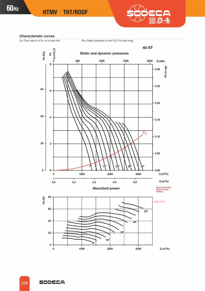
238
Characteristic curvesQ= Flow rate in m3/h, m3/s and cfm. Pe= Static pressure in mm H2O, Pa and inwg.
Absorbed power Recommended Motor Power kW(hp)
Static and dynamic pressures40‐6T
HTMV THT/ROOF

239
Characteristic curvesQ= Flow rate in m3/h, m3/s and cfm. Pe= Static pressure in mm H2O, Pa and inwg.
Absorbed power Recommended Motor Power kW(hp)
Static and dynamic pressures45‐4T
HTMV THT/ROOF HTMV THT/ROOF

240
Characteristic curvesQ= Flow rate in m3/h, m3/s and cfm. Pe= Static pressure in mm H2O, Pa and inwg.
Absorbed power Recommended Motor Power kW(hp)
Static and dynamic pressures45‐6T
HTMV THT/ROOF

241
Characteristic curvesQ= Flow rate in m3/h, m3/s and cfm. Pe= Static pressure in mm H2O, Pa and inwg.
Absorbed power Recommended Motor Power kW(hp)
Static and dynamic pressures50‐4T
HTMV THT/ROOF HTMV THT/ROOF

242
Characteristic curvesQ= Flow rate in m3/h, m3/s and cfm. Pe= Static pressure in mm H2O, Pa and inwg.
Absorbed power Recommended Motor Power kW(hp)
Static and dynamic pressures50‐6T
HTMV THT/ROOF

243
Characteristic curvesQ= Flow rate in m3/h, m3/s and cfm. Pe= Static pressure in mm H2O, Pa and inwg.
Absorbed power Recommended Motor Power kW(hp)
Static and dynamic pressures56‐4T
HTMV THT/ROOF HTMV THT/ROOF

244
Characteristic curvesQ= Flow rate in m3/h, m3/s and cfm. Pe= Static pressure in mm H2O, Pa and inwg.
Absorbed power Recommended Motor Power kW(hp)
Static and dynamic pressures56‐6T
HTMV THT/ROOF

245
Characteristic curvesQ= Flow rate in m3/h, m3/s and cfm. Pe= Static pressure in mm H2O, Pa and inwg.
Absorbed power Recommended Mo-tor Power kW(hp)
Static and dynamic pressures63‐4T
HTMV THT/ROOF HTMV THT/ROOF

246
Characteristic curvesQ= Flow rate in m3/h, m3/s and cfm. Pe= Static pressure in mm H2O, Pa and inwg.
Absorbed power Recommended Mo-tor Power kW(hp)
Static and dynamic pressures63‐6T
HTMV THT/ROOF

247
Characteristic curvesQ= Flow rate in m3/h, m3/s and cfm. Pe= Static pressure in mm H2O, Pa and inwg.
Absorbed power Recommended Motor Power kW(hp)
Static and dynamic pressures71‐4T
HTMV THT/ROOF HTMV THT/ROOF

248
Characteristic curvesQ= Flow rate in m3/h, m3/s and cfm. Pe= Static pressure in mm H2O, Pa and inwg.
Absorbed power Recommended Motor Power kW(hp)
Static and dynamic pressures71‐6T
HTMV THT/ROOF

249
Characteristic curvesQ= Flow rate in m3/h, m3/s and cfm. Pe= Static pressure in mm H2O, Pa and inwg.
Absorbed power Recommended Motor Power kW(hp)
Static and dynamic pressures80‐4T
HTMV THT/ROOF HTMV THT/ROOF

250
Characteristic curvesQ= Flow rate in m3/h, m3/s and cfm. Pe= Static pressure in mm H2O, Pa and inwg.
Absorbed power Recommended Motor Power kW(hp)
Static and dynamic pressures80‐6T
HTMV THT/ROOF

251
Characteristic curvesQ= Flow rate in m3/h, m3/s and cfm. Pe= Static pressure in mm H2O, Pa and inwg.
Absorbed power Recommended Motor Power kW(hp)
Static and dynamic pressures90‐4T
HTMV THT/ROOF HTMV THT/ROOF

252
Characteristic curvesQ= Flow rate in m3/h, m3/s and cfm. Pe= Static pressure in mm H2O, Pa and inwg.
Absorbed power Recommended Motor Power kW(hp)
Static and dynamic pressures90‐6T
HTMV THT/ROOF

253
Characteristic curvesQ= Flow rate in m3/h, m3/s and cfm. Pe= Static pressure in mm H2O, Pa and inwg.
Absorbed power Recommended Motor Power kW(hp)
Static and dynamic pressures100‐4T/6
HTMV THT/ROOF HTMV THT/ROOF
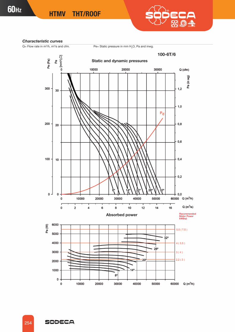
254
Characteristic curvesQ= Flow rate in m3/h, m3/s and cfm. Pe= Static pressure in mm H2O, Pa and inwg.
Absorbed power Recommended Motor Power kW(hp)
Static and dynamic pressures100‐6T/6
HTMV THT/ROOF

255
Characteristic curvesQ= Flow rate in m3/h, m3/s and cfm. Pe= Static pressure in mm H2O, Pa and inwg.
Absorbed power Recommended Motor Power kW(hp)
Static and dynamic pressures125‐4T/3
HTMV THT/ROOF HTMV THT/ROOF

256
Characteristic curvesQ= Flow rate in m3/h, m3/s and cfm. Pe= Static pressure in mm H2O, Pa and inwg.
Absorbed power Recommended Motor Power kW(hp)
Static and dynamic pressures125‐4T/6
HTMV THT/ROOF

257
Characteristic curvesQ= Flow rate in m3/h, m3/s and cfm. Pe= Static pressure in mm H2O, Pa and inwg.
Absorbed power Recommended Motor Power kW(hp)
Static and dynamic pressures125‐4T/9
HTMV THT/ROOF HTMV THT/ROOF

258
Characteristic curvesQ= Flow rate in m3/h, m3/s and cfm. Pe= Static pressure in mm H2O, Pa and inwg.
Absorbed power Recommended Motor Power kW(hp)
Static and dynamic pressures125‐6T/3
HTMV THT/ROOF

259
Characteristic curvesQ= Flow rate in m3/h, m3/s and cfm. Pe= Static pressure in mm H2O, Pa and inwg.
Absorbed power Recommended Motor Power kW(hp)
Static and dynamic pressures125‐6T/6
HTMV THT/ROOF HTMV THT/ROOF

260
Characteristic curvesQ= Flow rate in m3/h, m3/s and cfm. Pe= Static pressure in mm H2O, Pa and inwg.
Absorbed power Recommended Motor Power kW(hp)
Static and dynamic pressures125‐6T/9
HTMV THT/ROOF

261
HTMV THT/ROOF
Thanks to its knowledge gained during 25 years of experience in manufacturing fans for continuous operation at high temperatures, SODECA has become a specialist in the production of extractor fans for smoke evacuation in the event of fire and overpres-sure protection systems for smoke control in escape routes in the presence of fire.
Our production systems are certified by external control entities such as BUREAU VERITAS, and the quality controls performed on manufacturing processes and ex-tractor control for smoke evacuation at high temperatures are also audited in full by independent organisations such as APPLUS, thus ensuring their correct operation and that they comply with the legislation and technical characteristics established for ex-tractor fans.
All our extractor fans for smoke evacuation comply with European standard EN 12101-3:2002/AC:2006 “Powered smoke and heat exhaust ventilators for use in Construction Works”, and are certified by an independent laboratory and accredited by the Euro-pean directives.
EXTRACTOR FANS FOR SMOKE EVACUATIONIN THE EVENT OF FIRE
F-300 AND F-400 EXTRACTOR FANS FOR SMOKE EVACUATION IN CAR PARKS AND SIMILAR
F-400 CERTIFICATION
F-400
THT
TCR/R
THT/IMP
CJTCR/R
CI
CJTX-C
HTMF
CJSX
THT/ROOF
CSX
266
334
319
334
323
339
324
347
331
353
400 ºC/2h and 300 ºC/2h roof-mounted multifunctional extractor fans
400 ºC/2h and 300 ºC/2htubular axial extractor fans
400 ºC/2h centrifugal extractor fanwith reaction impeller
400 ºC/2h extractor fan units with reactionimpeller
400 ºC/2h extractor fan units with motor and belt drive insidebox
400 ºC/2h belt-driven, single inlet extractor fan units
400 ºC/2h belt-driven centrifugalextractor fans with reaction impeller
300 ºC/2h and 400 ºC/2h long range, induction centrifugal fans
300 ºC/2h and 400 ºC/2h long-range one-way or reversible jet fans with a circular or anoctagonal design
400 ºC/2h and 300 ºC/2h roof-mounted axial extractor fans with vertical air outlet

262
FANS FOR IMMERSED OPERATION
Installation of fan for immersed operation in fire risk zone
Smoke evacuation in: CAR PARKSSmoke evacuation method with certified extractor fans for operating at high tem-peratures for a certain length of time, based on their classification and certification. This method is normally applied in buildings, shopping centres, tunnels, car parks and other large constructions with vast open areas, in industrial warehouses with a high risk of fire, and for smoke extraction in industrial kitchens.
EXTERNAL FANS
Installation of outdoor fans in fire risk zone
JET FANSInstallation of jet fans for immersed operation in fire risk zones
THT/IMP-O CITHT/IMP-L
EXAMPLES OF APPLICATION
THT
CJSXCJTX-CCSX CJTCR/R TCR/R
CERTIFIED EXTRACTOR FANS FOR SMOKE EVACUATION IN THE EVENT OF FIRE

263
Extractor fans suitable for use in industrial kitchensFor the correct application of the standard:• C.T.E. Código Técnico de la Edificación (Technical Building Code). Basic
Document SI on fire safety. Basic Document HS on health and safety.
The overpressure smoke control method consists of pressurisation by injecting air into spaces which are used as escape routes by people in the case of fire, such as stairwells, corridors, passageways, lifts, etc., especially in tall buildings with large oc-cupancy. The method is based on smoke control by the air speed and the artificial bar-rier created by air overpressure on the smoke, preventing it from entering the escape routes. In accordance with the EN-12101-6-2006 standards:
Smoke evacuation in: INDUSTRIAL KITCHENS
Extractor fans suitable for use in industrial warehousesFor the correct application of the standard:• Regulations governing Fire Protection in Industrial Establishments, Royal
Decree 2267/2004, EN-23585:2004 Fire Protection
Smoke evacuation in: INDUSTRIAL WAREHOUSES
Smoke control by differential pressure systems for: EVACUATION ROUTES
STAIRCASE OVERPRESSURE KITFor three-phase equipment
KIT SOBREPRESIÓN WITH BACKUP FAN
STAIRCASE OVERPRESSURE KIT For single-phase equipment
CJSX
CJTX-CCSX
CJTCR/R TCR/R
THT HTMF THT/ROOF
EXAMPLES OF APPLICATION EXAMPLES OF APPLICATION
RFH RFV VC-HDU

264
CI installed in car park
Smoke machine for conducting real smoke tests
CI installed in car park
THT/IMP installed in car park

265
IMPULSE VENTILATIONAs an alternative to traditional ventilation systems, in recent years horizontal ventilation systems (also known as impulse or induction ventilation systems) have been implemented, using extraction duct networks and the supply of air.
This new technique is based on the reproduction of longi-tudinal ventilation systems used in tunnels, creating an air front with a speed that is sufficient to provoke a sweep of the area to be ventilated.
The installation of fans at the air and smoke inlet and outlet points gives rise to the induction phenomenon, extracting the mass of air/smoke to the exterior.
This ventilation system is based on the impulsion of a small quantity of air at high speed, which generates a homogenisation effect on the rest of the air.
In addition, the system makes it possible to maintain really low con-taminant gas levels, without having to start up the entire car park ventilation system.
By putting just two inductive fans into operation, or designing sector-based or phase ventilation systems and using a gas detection sys-tem, it is possible to achieve lower power consumption, less noise and extend the useful life of the equipment.
Impulse ventilation also enables the design of smoke-control sys-tems in the event of fire in accordance with the three objectives set by the British and Belgian standards, which constitute the basis used by the European Standardisation Committee to draft the future Euro-pean Standard on Car Park Smoke Control, EN 12101-11:
• Smoke extraction during and after fire (smoke clearance)
• Facilitate the work of the fire service (fire fighting)
• Facilitate the safe evacuation of occupants (means of escape)
SYSTEM BENEFITSThe two most important benefits of the impulse or induction ven-tilation system are:• Maintaining of a low contaminant gas concentration level• Increased safety in smoke control in the event of fire
Furthermore, these systems have the following additional benefits.• They are faster and easier to install and generate less interference
with other systems (sprinkler networks, electric ducts, drains)• Lower occupancy under the slab, thus facilitating the installa-
tion of the ventilation system in car parks with lower heights and a reduction in excavation costs.
• Greater visibility in the car park, with the ensuing improved performance of CCTV systems.
• Reduction in the use of the ventilation system, as the fans do not have to overcome duct load losses, with fewer start-ups and hours of operation.
JET FANS VENTILATION IN CAR PARKS
Examples of studies
using compu-tational fluid
dynamics (CFD) simulations

266
400 ºC/2h and 300 ºC/2h tubular axial extractor fansTHT400 ºC/2h tubular axial extractor fans with short casings for immersed operation in fire risk zones.
Fan:• Sheet steel tubular casing. • Cast aluminium orientable rotors.• Approved in accordance with standard EN-12101-3-2002.• Airflow direction from Motor to Impeller.
Motor:• Class H motors, S1 continuous operation
and S2 emergency use, with ball bearings, IP55 protection and with 1 or 2 speeds, depending on model.
• Multi voltage motor, special design valid for 220/380V 60Hz, 254/440V 60Hz, 265/460V 60Hz, 277/480V 60Hz
• Maximum temperature of air to be carried: S1 continuous operation -20 ºC +40 ºC, S2 operation 300 ºC/2h, 400 ºC/2h.
Finish: • Anti-corrosive finish of polyester
resin polymerised at 190 ºC, previously degreased with phosphate-free nanotechnological treatment.
On request:• Long case fans fitted with an inspection
hatch. • Rotors 100 % reversible.
Order code
From size 40 to size 100
From size 125 to size 160
THT 56 4T 2 F-400
Number of motor poles2=3500 r/min. 60 Hz4=1680 r/min. 60 Hz6=1080 r/min. 60 Hz8=900 r/min. 60 Hz12=750 r/min. 60 Hz
Rotor diameter in cm
THT: 400 ºC/2h and 300 ºC/2h tubular axial extractor fans
THT/CL: 400 ºC/2h and 300 ºC/2h tubular axial extractor fans with long casings, fitted with inspection hatches
T= Three-phase
F-300: 300 ºC/2h approvedF-400: 400 ºC/2h approved
Motorpower (hp)
60Hz
THT 125 4T 15 9-10 F-400
Number of motor poles2=3500 r/min. 60 Hz4=1680 r/min. 60 Hz6=1080 r/min. 60 Hz8=900 r/min. 60 Hz12=750 r/min. 60 Hz
Rotor diam-eter in cm
THT: 400 ºC/2h and 300 ºC/2h tubular axial extractor fans
THT/CL: 400 ºC/2h and 300 ºC/2h tubular axial extractor fans with long casings, fitted with inspection hatches
T= Three-phase
F-300: 300 ºC/2h approvedF-400: 400 ºC/2h approved
Number of blades3 blades6 blades 9 blades
Blade in-clination angle
Motorpower (c.v.)
60Hz
THT
0370-CPR-0305

267
THT THT
Technical characteristics
THT-40-2T-1.5 3455 4.70 2.70 1.10 6750 76 33 31THT-40-2/4T-1.5 3505/1750 2.90/2.10 1.10/0.25 6750/3400 76/61 34 32THT-40-2T-2 3455 5.90 3.40 1.50 7350 77 35 33THT-40-2/4T-2 3530/1750 4.40/1.40 1.50/0.37 7350/3650 77/62 35 33THT-40-4T-0.75 1690 2.73 1.57 0.55 5800 64 32 29THT-40-6T-0.75 1150 4.10 2.40 0.55 3800 53 37 34THT-40-6/12T-0.75 1130/530 1.60/0.55 0.55/0.09 3800/1750 53/38 41 38THT-45-2T-2 3455 5.90 3.40 1.50 8800 78 38 34THT-45-2/4T-2 3530/1750 5.70/1.80 1.50/0.37 8800/4400 78/63 37 34THT-45-2T-3 3480 8.70 5.00 2.20 11300 80 39 36THT-45-2/4T-3 3515/1740 4.40/1.40 2.20/0.60 11300/5650 80/65 39 36THT-45-4T-0.75 1690 2.73 1.57 0.55 7500 68 34 30THT-45-6T-0.75 1150 4.10 2.40 0.55 6050 55 38 35THT-45-6/12T-0.75 1130/530 1.60/0.55 0.55/0.09 6050/2800 55/40 42 39THT-50-2T-4 3455 11.20 6.50 3.00 12100 82 49 42THT-50-2/4T-4 3505/1730 6.70/2.00 3.00/0.80 12100/6050 82/67 51 44THT-50-2T-5.5 3470 9.30 4.00 14300 83 65 57THT-50-2/4T-6 3515/1740 10.00/3.20 4.50/1.30 15400/7700 83/68 67 60THT-50-4T-1 1700 3.50 2.03 0.75 8950 69 37 33THT-50-6T-0.75 1150 4.10 2.40 0.55 9150 57 40 36THT-50-6/12T-0.75 1130/530 1.60/0.55 0.55/0.09 9150/4250 57/42 44 40THT-56-2T-5.5 3505 9.50 4.00 18150 88 69 60THT-56-2/4T-6 3515/1740 10.00/3.20 4.50/1.30 19650/9800 88/72 71 63THT-56-2T-12 3540 19.20 9.00 27000 89 147 139THT-56-2/4T-12 3505/1730 20.70/5.50 9.00/2.50 27000/13500 89/74 137 129THT-56-4T-1 1715 3.50 2.00 0.75 10550 73 45 40THT-56-4T-1.5 1715 4.80 2.80 1.10 12750 74 44 40THT-56-4/8T-1.5 1730/850 2.90/1.40 1.10/0.25 12750/6300 74/59 48 43THT-56-4T-2 1705 6.20 3.60 1.50 15000 75 48 43THT-56-4/8T-2 1700/860 3.60/1.50 1.50/0.30 15000/7400 75/60 59 55THT-56-6T-0.75 1150 4.10 2.40 0.55 10650 62 44 39THT-56-6/12T-0.75 1130/530 1.60/0.55 0.55/0.09 10650/4950 62/47 48 43THT-63-2T-12 3540 19.20 9.00 33100 90 161 143THT-63-2/4T-12 3505/1730 18.50/5.50 9.00/2.50 33100/16550 90/75 151 133THT-63-2T-22 3550 32.30 16.00 44750 91 188 170THT-63-2/4T-22 3550/1775 32.30/8.90 16.00/4.00 44750/22400 91/76 188 170THT-63-4T-1 1715 3.50 2.00 0.75 13800 73 49 43THT-63-4T-1.5 1715 4.80 2.80 1.10 16550 74 51 45THT-63-4/8T-1.5 1730/850 2.90/1.40 1.10/0.25 16550/8200 74/59 55 49THT-63-4T-2 1705 6.20 3.60 1.50 19100 75 55 49THT-63-4/8T-2 1700/860 3.60/1.50 1.50/0.30 19100/9450 75/60 70 60THT-63-4T-3 1715 9.00 5.20 2.20 22400 76 64 54THT-63-4/8T-3 1700/860 5.20/1.90 2.20/0.45 22400/11050 76/61 77 66THT-63-4T-4 1715 11.40 6.60 3.00 25150 77 73 63THT-63-4/8T-4 1710/850 6.80/2.20 3.00/0.60 25150/12450 77/62 86 77THT-63-6T-0.75 1150 4.10 2.40 0.55 14650 65 51 45THT-63-6/12T-0.75 1130/530 1.60/0.55 0.55/0.09 14650/6800 65/50 55 49THT-63-6T-1 1140 4.70 2.70 0.75 15900 66 54 48THT-63-6/12T-1 1130/530 2.20/0.87 0.75/0.15 15900/7400 66/51 61 55THT-71-4T-1.5 1715 4.80 2.80 1.10 19950 78 58 52THT-71-4/8T-1.5 1730/850 2.90/1.40 1.10/0.25 19950/9850 78/63 61 56THT-71-4T-2 1705 6.20 3.60 1.50 19950 79 61 56THT-71-4/8T-2 1700/860 3.60/1.50 1.50/0.30 19950/9850 79/64 76 67THT-71-4T-3 1715 9.00 5.20 2.20 25250 81 70 61THT-71-4/8T-3 1700/860 5.20/1.90 2.20/0.45 25250/12450 81/66 82 74THT-71-4T-4 1715 11.40 6.60 3.00 28100 82 79 70THT-71-4/8T-4 1710/850 6.80/2.20 3.00/0.60 28100/13900 82/67 92 83THT-71-6T-0.75 1150 4.10 2.40 0.55 15400 67 57 52
Model Speed Maximum admissible current (A)
Installed power
Maximum flow rate
Sound pressure level
Approx. weight(kg)
(r/min) 220-277V 380-480V (kW) (m3/h) dB(A) Long Short

268
Technical characteristics
THT
THT-71-6/12T-0.75 1130/530 1.60/0.55 0.55/0.09 15400/7150 67/52 61 56THT-71-6T-1 1140 4.70 2.70 0.75 17450 68 61 55THT-71-6/12T-1 1130/530 2.20/0.87 0.75/0.15 17450/8100 68/53 67 62THT-71-6T-1.5 1130 5.50 3.20 1.10 20300 69 69 61THT-71-6/12T-1.5 1140/565 3.00/1.15 1.10/0.18 20300/9450 69/54 77 69THT-80-4T-3 1715 9.00 5.20 2.20 25050 82 79 69THT-80-4/8T-3 1700/860 5.20/1.90 2.20/0.45 25050/12400 82/67 91 82THT-80-4T-4 1715 11.40 6.60 3.00 27850 83 88 78THT-80-4/8T-4 1710/850 6.80/2.20 3.00/0.60 27850/13750 83/68 101 92THT-80-4T-5.5 1720 8.40 4.00 33450 84 94 85THT-80-4/8T-5.5 1745/870 9.30/3.40 4.00/0.80 33450/16550 84/69 127 118THT-80-6T-1.5 1130 5.50 3.20 1.10 20100 72 78 69THT-80-6/12T-1.5 1140/565 3.00/1.15 1.10/0.18 20100/9350 72/57 86 77THT-80-6T-2 1135 7.40 4.30 1.50 23900 73 87 78THT-80-6/12T-2 1140/550 4.60/1.90 1.50/0.25 23900/11100 73/58 91 82THT-80-6T-3 1120 9.50 5.50 2.20 30150 74 94 84THT-80-6/12T-3 1130/565 5.60/2.20 2.20/0.37 30150/14000 74/59 100 91THT-80-8T-0.75 840 3.60 2.10 0.55 16550 70 71 62THT-80-8T-1 850 4.80 2.80 0.75 19550 71 78 69THT-90-4T-4 1715 11.40 6.60 3.00 34700 87 110 93THT-90-4/8T-4 1710/850 6.80/2.20 3.00/0.60 34700/17150 87/72 124 106THT-90-4T-5.5 1720 8.40 4.00 39900 89 117 99THT-90-4/8T-5.5 1745/870 9.30/3.40 4.00/0.80 39900/19700 89/74 150 132THT-90-4T-7.5 1750 12.60 5.50 43350 91 143 126THT-90-4/8T-7.5 1745/870 12.80/4.60 5.50/1.10 43350/21450 91/76 157 140THT-90-4T-10 1750 17.70 7.50 50000 92 154 137THT-90-4/8T-9 1745/870 15.60/6.30 6.70/1.50 46850/23150 92/77 157 140THT-90-6T-2 1135 7.40 4.30 1.50 28400 77 110 92THT-90-6/12T-2 1140/550 4.60/1.90 1.50/0.25 28400/13200 77/62 114 96THT-90-6T-3 1120 9.50 5.50 2.20 32750 78 116 99THT-90-6/12T-3 1130/565 5.60/2.20 2.20/0.37 32750/15250 78/63 123 105THT-90-6T-4 1165 13.50 7.80 3.00 38150 79 142 124THT-90-6/12T-4 1150/570 8.90/3.50 3.00/0.55 38150/17750 79/64 143 126THT-90-8T-1 850 4.80 2.80 0.75 23150 71 100 84THT-90-8T-2 850 7.80 4.50 1.50 29850 73 116 99THT-90-8T-3 850 11.40 6.60 2.20 35350 74 134 116THT-100-4T-7.5 1750 12.60 5.50 51700 92 151 131THT-100-4/8T-7.5 1745/870 12.80/4.60 5.50/1.10 46950/23200 92/77 165 145THT-100-4T-10 1750 17.70 7.50 56400 93 162 142THT-100-4/8T-9 1745/870 15.60/6.30 6.70/1.50 56400/27900 93/78 165 145THT-100-4T-15 1750 22.00 11.00 65850 94 215 195THT-100-4/8T-15 1765/870 23.20/8.70 11.00/2.80 65850/32550 94/79 215 195THT-100-4T-20 1750 29.00 15.00 72500 95 230 210THT-100-4/8T-20 1765/870 31.70/11.80 15.00/3.80 72500/35850 95/80 230 210THT-100-6T-3 1120 9.50 5.50 2.20 36950 82 124 105THT-100-6/12T-3 1130/565 5.60/2.20 2.20/0.37 36950/17200 82/67 130 112THT-100-6T-4 1165 13.50 7.80 3.00 43150 83 150 130THT-100-6/12T-4 1150/570 8.90/3.50 3.00/0.55 43150/20050 83/68 151 131THT-100-6T-5.5 1165 11.00 4.00 47500 84 162 142THT-100-6/12T-5.5 1165/575 11.30/4.20 4.00/0.65 47500/22100 84/69 162 142THT-100-8T-2 850 7.80 4.50 1.50 32550 77 124 105THT-100-8T-3 850 11.40 6.60 2.20 37450 77 142 122THT-100-8T-4 850 15.60 9.00 3.00 43400 78 162 142THT-125-4T/3-10 1750 17.70 7.50 54400 88 243 210THT-125-4/8T/3-9 1745/870 15.60/6.30 6.70/1.50 50550/25000 88/68 243 210THT-125-4T/3-15 1750 22.00 11.00 69800 89 294 266THT-125-4/8T/3-15 1765/870 23.20/8.70 11.00/2.80 69800/34500 89/69 294 266THT-125-4T/3-20 1750 29.00 15.00 77500 91 309 281
Model Speed Maximum admissible current (A)
Installed power
Maximum flow rate
Sound pressure level
Approx. weight(kg)
(r/min) 220-277V 380-480V (kW) (m3/h) dB(A) Long Short

269
THT THT
Technical characteristics
THT-125-4/8T/3-20 1765/870 31.70/11.80 15.00/3.80 77500/38300 91/71 309 281THT-125-4T/3-25 1760 37.00 18.50 92950 91 377 334THT-125-4T/3-30 1765 42.00 22.00 101300 92 391 348THT-125-4/8T/3-27 1765/880 38.00/13.00 20.00/4.00 92950/45950 92/71 391 348THT-125-4/8T/3-37 1770/880 51.00/20.60 27.00/6.00 118000/58350 93/72 472 429THT-125-4T/3-40 1770 58.00 30.00 118000 93 472 429THT-125-4/8T/3-40 1775/880 62.00/27.00 30.00/10.00 118000/58350 93/72 618 562THT-125-4T/6-20 1750 29.00 15.00 69250 89 318 290THT-125-4/8T/6-20 1765/870 31.70/11.80 15.00/3.80 73400/36250 89/68 318 290THT-125-4/8T/6-22 1765/880 31.80/12.00 16.50/3.30 77500/38300 89/69 303 275THT-125-4T/6-25 1760 37.00 18.50 81600 90 386 343THT-125-4/8T/6-27 1765/880 38.00/13.00 20.00/4.00 85750/42350 90/69 400 357THT-125-4T/6-30 1765 42.00 22.00 93950 90 400 357THT-125-4/8T/6-37 1770/880 51.00/20.60 27.00/6.00 102200/50500 90/70 481 437THT-125-4T/6-40 1770 58.00 30.00 110400 92 481 437THT-125-4/8T/6-40 1775/880 62.00/27.00 30.00/10.00 110400/54600 92/71 627 571THT-125-4T/6-50 1775 73.00 37.00 117700 93 529 473THT-125-4T/9-25 1760 37.00 18.50 69850 88 395 352THT-125-4/8T/9-22 1765/880 31.80/12.00 16.50/3.30 59500/29400 88/69 312 284THT-125-4T/9-30 1765 42.00 22.00 85350 89 409 366THT-125-4/8T/9-27 1765/880 38.00/13.00 20.00/4.00 75000 89/70 409 366THT-125-4/8T/9-37 1770/880 51.00/20.60 27.00/6.00 85350/42200 90/70 490 446THT-125-4T/9-40 1770 58.00 30.00 95700 91 490 446THT-125-4/8T/9-40 1775/880 62.00/27.00 30.00/10.00 95700/47300 91/71 636 580THT-125-4T/9-50 1775 73.00 37.00 106050 93 538 482THT-125-6T/3-4 1165 13.50 7.80 3.00 35650 79 230 197THT-125-6/12T/3-4 1150/570 8.90/3.50 3.00/0.55 40700/18900 79/64 232 199THT-125-6T/3-5.5 1165 11.00 4.00 50800 80 242 209THT-125-6/12T/3-5.5 1165/575 11.30/4.20 4.00/0.65 50800/23600 80/65 243 210THT-125-6T/3-7.5 1165 12.40 5.50 60900 81 249 216THT-125-6/12T/3-7.5 1165/575 13.20/5.30 5.50/1.00 60900/28300 81/66 263 230THT-125-6T/3-10 1165 17.00 7.50 71850 83 274 246THT-125-6/12T/3-10 1150/565 20.00/9.00 7.50/1.40 71850/33400 83/68 294 266THT-125-6T/3-15 1145 26.00 11.00 91650 84 304 276THT-125-6/12T/3-15 1150/565 28.50/13.00 11.00/2.00 91650/42600 84/69 309 281THT-125-6T/3-20 1170 31.00 15.00 101650 85 377 334THT-125-6/12T/3-24 1165/575 36.00/14.50 17.50/3.50 104450/48550 85/70 472 429THT-125-6T/6-5.5 1165 11.00 4.00 45400 77 251 218THT-125-6/12T/6-5.5 1165/575 11.30/4.20 4.00/0.65 50750/23600 77/62 252 219THT-125-6T/6-7.5 1165 12.40 5.50 56150 77 258 225THT-125-6/12T/6-7.5 1165/575 13.20/5.30 5.50/1.00 56150/26100 77/62 272 239THT-125-6T/6-10 1165 17.00 7.50 66950 79 283 255THT-125-6/12T/6-10 1150/565 20.00/9.00 7.50/1.40 66950/31150 79/64 303 275THT-125-6T/6-15 1145 26.00 11.00 81900 81 313 285THT-125-6/12T/6-15 1150/565 28.50/13.00 11.00/2.00 81900/38100 81/66 318 290THT-125-6T/6-20 1170 31.00 15.00 91950 82 386 343THT-125-6/12T/6-24 1165/575 36.00/14.50 17.50/3.50 102550/47700 82/67 481 437THT-125-6T/9-10 1165 17.00 7.50 55900 78 292 264THT-125-6/12T/9-10 1150/565 20.00/9.00 7.50/1.40 55900/26000 78/63 312 284THT-125-6T/9-15 1145 26.00 11.00 76250 81 322 294THT-125-6/12T/9-15 1150/565 28.50/13.00 11.00/2.00 76250/35450 81/66 327 299THT-125-6T/9-20 1170 31.00 15.00 87450 84 395 352THT-125-6/12T/9-24 1165/575 36.00/14.50 17.50/3.50 93050/43250 84/69 490 446THT-140-6T/3-5.5 1130 8.72 4.00 47700 83 279 242THT-140-6T/3-7.5 1150 12.20 5.50 61200 84 287 250THT-140-6T/3-10 1165 15.60 7.50 67950 85 339 300THT-140-6T/3-15 1165 23.30 11.00 88800 86 356 317THT-140-6T/3-20 1165 27.40 15.00 103450 88 436 386
Model Speed Maximum admissible current (A)
Installed power
Maximum flow rate
Sound pressure level
Approx. weight(kg)
(r/min) 220-277V 380-480V (kW) (m3/h) dB(A) Long Short

270
Technical characteristics
THT
THT-140-6T/6-7.5 1150 12.20 5.50 60700 84 297 260THT-140-6T/6-10 1165 15.60 7.50 67950 85 349 310THT-140-6T/6-15 1165 23.30 11.00 82350 86 366 327THT-140-6T/6-20 1165 27.40 15.00 96800 87 445 396THT-140-6T/6-25 1170 34.40 18.50 103200 88 497 448THT-140-6T/6-30 1170 41.40 22.00 116000 89 506 457THT-140-6T/9-10 1165 15.60 7.50 56700 84 358 319THT-140-6T/9-15 1165 23.30 11.00 74850 86 375 336THT-140-6T/9-20 1165 27.40 15.00 83900 87 455 405THT-140-6T/9-25 1170 34.40 18.50 102050 88 506 458THT-140-6T/9-30 1170 41.40 22.00 109500 89 515 467THT-140-6T/9-40 1180 54.20 30.00 124500 91 673 611THT-140-6T/9-50 1175 66.40 37.00 133300 92 751 696THT-140-8T/3-3 860 9.17 5.27 2.20 41050 78 279 242THT-140-8T/3-4 850 12.50 7.20 3.00 51250 78 287 250THT-140-8T/3-5.5 875 10.40 4.00 61450 79 337 298THT-140-8T/3-7.5 875 13.80 5.50 72500 81 346 307THT-140-8T/3-10 870 17.80 7.50 87700 82 357 318THT-140-8T/6-3 860 9.17 5.27 2.20 45800 78 289 252THT-140-8T/6-4 850 12.50 7.20 3.00 51250 79 297 260THT-140-8T/6-5.5 875 10.40 4.00 56700 80 347 308THT-140-8T/6-7.5 875 13.80 5.50 67600 81 356 317THT-140-8T/6-10 870 17.80 7.50 77850 82 367 328THT-140-8T/6-15 870 21.70 11.00 92850 83 453 404THT-140-8T/9-4 850 12.50 7.20 3.00 42750 79 306 269THT-140-8T/9-5.5 875 10.40 4.00 49600 79 356 317THT-140-8T/9-7.5 875 13.80 5.50 56450 81 365 326THT-140-8T/9-10 870 17.80 7.50 70150 82 376 337THT-140-8T/9-15 870 21.70 11.00 82600 83 463 413THT-140-8T/9-20 870 32.90 15.00 100550 86 516 468THT-160-6T/3-10 1165 15.60 7.50 71150 83 412 358THT-160-6T/3-15 1165 23.30 11.00 91350 85 429 375THT-160-6T/3-20 1165 27.40 15.00 101450 86 522 453THT-160-6T/3-25 1170 34.40 18.50 121600 87 574 504THT-160-6T/3-30 1170 41.40 22.00 132550 89 583 513THT-160-6T/6-15 1165 23.30 11.00 90650 85 440 386THT-160-6T/6-20 1165 27.40 15.00 101400 86 532 463THT-160-6T/6-25 1170 34.40 18.50 112200 87 584 515THT-160-6T/6-30 1170 41.40 22.00 122950 88 593 524THT-160-6T/6-40 1180 54.20 30.00 144500 89 768 669THT-160-6T/6-50 1175 66.40 37.00 163600 91 842 757THT-160-6T/9-15 1165 23.30 11.00 71100 85 450 396THT-160-6T/9-20 1165 27.40 15.00 84600 86 542 473THT-160-6T/9-25 1170 34.40 18.50 98150 87 594 525THT-160-6T/9-30 1170 41.40 22.00 111700 88 603 534THT-160-6T/9-40 1180 54.20 30.00 125250 89 778 679THT-160-6T/9-50 1175 66.40 37.00 152300 90 852 768THT-160-6T/9-60 1180 84.50 45.00 163500 91 1067 968THT-160-6T/9-75 1180 100.00 55.00 174650 92 1112 1013THT-160-8T/3-4 850 12.50 7.20 3.00 53700 77 356 304THT-160-8T/3-5.5 875 10.40 4.00 61300 79 410 356THT-160-8T/3-7.5 875 13.80 5.50 68900 80 419 365THT-160-8T/3-10 870 17.80 7.50 84150 81 430 376THT-160-8T/3-15 870 21.70 11.00 108250 83 530 461THT-160-8T/6-5.5 875 10.40 4.00 68350 77 421 367THT-160-8T/6-7.5 875 13.80 5.50 76500 79 430 376THT-160-8T/6-10 870 17.80 7.50 84650 80 441 387THT-160-8T/6-15 870 21.70 11.00 100900 82 540 471
Model Speed Maximum admissible current (A)
Installed power
Maximum flow rate
Sound pressure level
Approx. weight(kg)
(r/min) 220-277V 380-480V (kW) (m3/h) dB(A) Long Short

271
THT
Technical characteristics
Model 63 125 250 500 1000 2000 4000 8000 Model 63 125 250 500 1000 2000 4000 8000
The indicated values are determined by measuring the sound pressure level and sound power in dB(A) obtained in a free field at a distance equivalent to twice the size of the fan plus the rotor diameter, with a minimum of 1.5 m.
Acoustic characteristics
Sound power spectrum Lw(A) in dB(A) per Hz frequency band
40-2-1.5 48 69 76 81 84 80 73 6240-2-2 49 70 77 82 85 81 74 6340-4-0.75 36 57 64 69 72 68 61 5040-4-1.5 33 54 61 66 69 65 58 4740-4-2 34 55 62 67 70 66 59 4840-6 25 46 53 58 61 57 50 3940-12 10 31 38 43 46 42 35 2445-2-2 50 71 78 83 86 82 75 6445-2-3 52 73 80 85 88 84 77 6645-4-0.75 40 61 68 73 76 72 65 5445-4-2 35 56 63 68 71 67 60 4945-4-3 37 58 65 70 73 69 62 5145-6 27 48 55 60 63 59 52 4145-12 12 33 40 45 48 44 37 2650-2-4 57 77 85 90 92 89 82 7150-2-5.5 58 78 86 91 93 90 83 7250-2-6 58 78 86 91 93 90 83 7250-4-1 44 64 72 77 79 76 69 5850-4-4 42 62 70 75 77 74 67 5650-4-6 43 63 71 76 78 75 68 5750-6 32 52 60 65 67 64 57 4650-12 17 37 45 50 52 49 42 3150-2-5.5 63 83 91 96 98 95 88 7756-2-6 63 83 91 96 98 95 88 7756-2-12 64 84 92 97 99 96 89 7856-4-1 48 68 76 81 83 80 73 6256-4-1.5 49 69 77 82 84 81 74 6356-4-2 50 70 78 83 85 82 75 6456-4-6 48 68 76 81 83 80 73 6256-4-12 49 69 77 82 84 81 74 6356-6 37 57 65 70 72 69 62 5156-8-1.5 34 54 62 67 69 66 59 4856-8-2 35 55 63 68 70 67 60 4956-12 22 42 50 55 57 54 47 3663-2-12 67 87 95 100 102 99 92 8163-2-22 68 88 96 101 103 100 93 8263-4-1 50 70 78 83 85 82 75 6463-4-1.5 48 68 76 81 83 80 73 6563-4-2 52 68 76 81 83 80 73 6663-4-3 53 70 78 83 85 82 77 6763-4-4 54 71 79 84 86 83 78 6863-4-12 52 72 80 85 87 84 77 6663-4-22 53 73 81 86 88 85 78 6763-6-0.75 42 60 68 73 75 72 65 5663-6-1 43 62 70 75 77 74 67 5763-8-1.5 33 53 61 66 68 65 58 5063-8-2 37 53 61 66 68 65 58 5163-8-3 38 55 63 68 70 67 62 5263-8-4 39 56 64 69 71 68 63 5363-12-0.75 27 43 51 56 58 55 48 3763-12-1 28 45 53 58 60 57 50 4271-4-1.5 54 74 82 87 89 86 79 6971-4-2 53 73 81 86 88 85 78 7071-4-3 58 72 80 85 87 84 77 7171-4-4 59 73 81 86 88 85 78 7271-6-0.75 44 63 72 74 76 73 66 5571-6-1 45 65 73 75 77 74 67 5671-6-1.5 46 66 71 76 78 75 68 5771-8-1.5 38 58 66 71 73 70 63 5471-8-2 38 58 66 71 73 70 63 5571-8-3 43 57 65 70 72 69 62 5671-8-4 44 58 66 71 73 70 63 57
71-12-0.75 29 44 52 57 59 56 49 3871-12-1 30 46 54 59 61 58 51 4071-12-1.5 31 46 54 59 61 58 51 4080-4-3 57 77 85 90 92 89 82 7380-4-4 56 76 84 89 91 88 81 7480-4-5.5 56 76 84 89 91 88 81 7080-6-1.5 49 66 74 79 81 78 71 6080-6-2 50 67 75 80 82 79 72 6180-6-3 51 68 76 81 83 80 73 6280-8-0.75 47 60 68 73 75 72 65 5480-8-1 48 61 69 74 76 73 66 5580-8-3 42 62 70 75 77 74 67 5880-8-4 41 61 69 74 76 73 66 5980-8-5.5 40 60 68 73 75 72 65 5980-12-1.5 34 49 57 62 64 61 54 4380-12-2 35 50 58 63 65 62 55 4480-12-3 36 51 59 64 66 63 56 4590-4-4 61 82 89 94 97 93 86 7990-4-5.5 60 81 88 93 96 92 85 7490-4-7.5 59 80 87 92 95 91 84 7390-4-9 58 79 86 91 94 90 83 7290-4-10 58 79 86 91 94 90 83 7290-6-2 49 70 77 82 85 81 74 6390-6-3 56 70 77 82 85 81 74 6390-6-4 57 72 79 84 87 83 76 6590-8-1 42 63 70 75 78 74 67 5690-8-2 51 66 73 78 81 77 70 5990-8-3 52 66 73 78 81 77 70 5990-8-4 46 67 74 79 82 78 71 6490-8-5.5 45 66 73 78 81 77 70 5990-8-7.5 43 64 71 76 79 75 68 5790-8-9 43 64 71 76 79 75 68 5790-12-2 32 53 60 65 68 64 57 4690-12-3 41 53 60 65 68 64 57 4690-12-4 42 55 62 67 70 66 59 48100-4-7.5 64 84 92 97 99 96 89 78100-4-9 63 83 91 96 98 95 88 77100-4-10 62 82 90 95 97 94 87 76100-4-15 61 81 89 94 96 93 86 75100-4-20 63 83 91 96 98 95 88 77100-6-3 61 72 80 85 87 84 77 66100-6-4 64 72 80 85 87 84 77 66100-6-5.5 64 73 81 86 88 85 78 67100-8-2 56 66 74 79 81 78 71 60100-8-3 57 68 76 81 83 80 73 62100-8-4 58 68 76 81 83 80 73 62100-8-7.5 49 69 77 82 84 81 74 63100-8-9 48 68 76 81 83 80 73 62100-8-15 46 66 74 79 81 78 71 60100-8-20 47 67 75 80 82 79 72 61100-12-3 46 55 63 68 70 67 60 49100-12-4 48 55 63 68 70 67 60 49100-12-5.5 49 56 64 69 71 68 61 50125-4/3-9 70 76 88 98 98 94 86 82125-4/3-10 70 76 88 98 98 94 86 82125-4/3-15 71 77 89 99 99 95 87 83125-4/3-20 73 79 91 101 101 97 89 85125-4/3-25 73 79 91 101 101 97 89 85125-4/3-27 74 80 92 102 102 98 90 86125-4/3-30 74 80 92 102 102 98 90 86125-4/3-37 75 81 93 103 103 99 91 87125-4/3-40 75 81 93 103 103 99 91 87
THT
THT-160-8T/6-20 870 32.90 15.00 116200 83 594 525THT-160-8T/6-25 875 34.90 18.50 130600 84 741 642THT-160-8T/9-7.5 875 13.80 5.50 63850 79 440 386THT-160-8T/9-10 870 17.80 7.50 74050 80 451 397THT-160-8T/9-15 870 21.70 11.00 84250 82 550 481THT-160-8T/9-20 870 32.90 15.00 104700 83 604 535THT-160-8T/9-25 875 34.90 18.50 114900 84 751 652THT-160-8T/9-30 875 41.10 22.00 131750 85 776 677THT-160-8T/9-40 875 56.30 30.00 150100 86 837 753
Model Speed Maximum admissible current (A)
Installed power
Maximum flow rate
Sound pressure level
Approx. weight(kg)
(r/min) 220-277V 380-480V (kW) (m3/h) dB(A) Long Short

272
Acoustic characteristicsSound power spectrum Lw(A) in dB(A) per Hz frequency band
125-6/3-5.5 66 74 86 90 88 83 74 70125-6/3-7.5 67 75 87 91 89 84 75 71125-6/3-10 69 77 89 93 91 86 77 73125-6/3-15 70 78 90 94 92 87 78 74125-6/3-20 71 79 91 95 93 88 79 75125-6/3-24 71 79 91 95 93 88 79 75125-8/3-9 50 56 68 78 78 74 66 62125-8/3-15 51 57 69 79 79 75 67 63125-8/3-20 53 59 71 81 81 77 69 65125-8/3-27 53 59 71 81 81 77 69 65125-8/3-37 54 60 72 82 82 78 70 66125-8/3-40 54 60 72 82 82 78 70 66125-6/3-4 65 73 85 89 87 82 73 69125-12/3-4 50 58 70 74 72 67 58 54125-12/3-5.5 51 59 71 75 73 68 59 55125-12/3-7.5 52 60 72 76 74 69 60 56125-12/3-10 54 62 74 78 76 71 62 58125-12/3-15 55 63 75 79 77 72 63 59125-12/3-24 56 64 76 80 78 73 64 60125-4/6-20 67 75 91 98 100 95 89 85125-4/6-22 67 75 91 98 100 95 89 85125-4/6-25 68 76 92 99 101 96 90 86125-4/6-27 68 76 92 99 101 96 90 86125-4/6-30 68 76 92 99 101 96 90 86125-4/6-37 68 76 92 99 101 96 90 86125-4/6-40 70 78 94 101 103 98 92 88125-4/6-50 71 79 95 102 104 99 93 89125-6/6-5.5 60 69 82 85 86 83 72 68125-6/6-7.5 60 69 82 85 86 83 72 68125-6/6-10 62 71 84 87 88 85 74 70125-6/6-15 64 73 86 89 90 87 76 72125-6/6-20 65 74 87 90 91 88 77 73125-6/6-24 65 74 87 90 91 88 77 73125-8/6-20 46 54 70 77 79 74 68 64125-8/6-22 47 55 71 78 80 75 69 65125-8/6-27 47 55 71 78 80 75 69 65125-8/6-37 48 56 72 79 81 76 70 66125-8/6-40 49 57 73 80 82 77 71 67125-12/6-5.5 45 54 67 70 71 68 57 53125-12/6-7.5 45 54 67 70 71 68 57 53125-12/6-10 47 56 69 72 73 70 59 55125-12/6-15 49 58 71 74 75 72 61 57125-12/6-24 50 59 72 75 76 73 62 58125-4/9-22 66 74 91 97 98 93 88 84125-4/9-25 66 74 91 97 98 93 88 84125-4/9-27 67 75 92 98 99 94 89 85125-4/9-30 67 75 92 98 99 94 89 85125-4/9-37 68 76 93 99 100 95 90 86125-4/9-40 69 77 94 100 101 96 91 87125-4/9-50 71 79 96 102 103 98 93 89125-6/9-10 58 68 83 87 86 85 74 70125-6/9-15 61 71 86 90 89 88 77 73125-6/9-20 64 74 89 93 92 91 80 76125-6/9-24 64 74 89 93 92 91 80 76125-8/9-22 47 55 72 78 79 74 69 65125-8/9-27 48 56 73 79 80 75 70 66125-8/9-37 48 56 73 79 80 75 70 66125-8/9-40 49 57 74 80 81 76 71 67125-12/9-10 43 53 68 72 71 70 59 55125-12/9-15 46 56 71 75 74 73 62 58125-12/9-24 49 59 74 78 77 76 65 61140-6/3-5.5 69 79 87 92 91 90 77 77140-6/3-7.5 70 80 88 93 92 91 78 78140-6/3-10 71 81 89 94 93 92 79 79140-6/3-15 72 82 90 95 94 93 80 80140-6/3-20 74 84 92 97 96 95 82 82140-6/6-7.5 68 83 92 94 91 85 77 73
140-6/6-10 69 84 93 95 92 86 78 74140-6/6-15 70 85 94 96 93 87 79 75140-6/6-20 71 86 95 97 94 88 80 76140-6/6-25 72 87 96 98 95 89 81 77140-6/6-30 73 88 97 99 96 90 82 78140-6/9-10 66 84 93 92 91 87 78 73140-6/9-15 68 86 95 94 93 89 80 75140-6/9-20 69 87 96 95 94 90 81 76140-6/9-25 70 88 97 96 95 91 82 77140-6/9-30 71 89 98 97 96 92 83 78140-6/9-40 73 91 100 99 98 94 85 80140-6/9-50 74 92 101 100 99 95 86 81140-8/3-3 64 74 82 87 86 85 72 67140-8/3-4 64 74 82 87 86 85 72 67140-8/3-5.5 65 75 83 88 87 86 73 68140-8/3-7.5 67 77 85 90 89 88 75 70140-8/3-10 68 78 86 91 90 89 76 71140-8/6-3 63 75 84 88 86 80 70 67140-8/6-4 64 76 85 89 87 81 71 68140-8/6-5.5 65 77 86 90 88 82 72 69140-8/6-7.5 66 78 87 91 89 83 73 70140-8/6-10 67 79 88 92 90 84 74 71140-8/6-15 68 80 89 93 91 85 75 72140-8/9-4 62 73 84 89 87 83 73 68140-8/9-5.5 62 73 84 89 87 83 73 68140-8/9-7.5 64 75 86 91 89 85 75 70140-8/9-10 65 76 87 92 90 86 76 71140-8/9-15 66 77 88 93 91 87 77 72140-8/9-20 69 80 91 96 94 90 80 75160-6/3-10 69 79 87 92 91 90 77 72160-6/3-15 71 81 89 94 93 92 79 74160-6/3-20 72 82 90 95 94 93 80 75160-6/3-25 73 83 91 96 95 94 81 76160-6/3-30 75 85 93 98 97 96 83 78160-6/6-15 69 84 93 95 92 86 78 74160-6/6-20 70 85 94 96 93 87 79 75160-6/6-25 71 86 95 97 94 88 80 76160-6/6-30 72 87 96 98 95 89 81 77160-6/6-40 73 88 97 99 96 90 82 78160-6/6-50 75 90 99 101 98 92 84 80160-6/9-15 67 85 94 93 92 88 79 74160-6/9-20 68 86 95 94 93 89 80 75160-6/9-25 69 87 96 95 94 90 81 76160-6/9-30 70 88 97 96 95 91 82 77160-6/9-40 71 89 98 97 96 92 83 78160-6/9-50 72 90 99 98 97 93 84 79160-6/9-60 73 91 100 99 98 94 85 80160-6/9-75 74 92 101 100 99 95 86 81160-8/3-4 63 73 81 86 85 84 71 66160-8/3-5.5 65 75 83 88 87 86 73 68160-8/3-7.5 66 76 84 89 88 87 74 69160-8/3-10 67 77 85 90 89 88 75 70160-8/3-15 69 79 87 92 91 90 77 72160-8/6-5.5 61 76 85 87 84 78 70 66160-8/6-7.5 63 78 87 89 86 80 72 68160-8/6-10 64 79 88 90 87 81 73 69160-8/6-15 66 81 90 92 89 83 75 71160-8/6-20 67 82 91 93 90 84 76 72160-8/6-25 68 83 92 94 91 85 77 73160-8/9-7.5 61 79 88 87 86 82 73 68160-8/9-10 62 80 89 88 87 83 74 69160-8/9-15 64 82 91 90 89 85 76 71160-8/9-20 65 83 92 91 90 86 77 72160-8/9-25 66 84 93 92 91 87 78 73160-8/9-30 67 85 94 93 92 88 79 74160-8/9-40 68 86 95 94 93 89 80 75
P-400 R RI
Accessories
INT IAT C2VCABLE BOX AET CENTRAL CO
THT
VSD3/A-RFT
THT
Model 63 125 250 500 1000 2000 4000 8000 Model 63 125 250 500 1000 2000 4000 8000

273
Dimensions mm
THT
Motor construction sizes, depending on power (1 speed)
hp
0.75 1 1.5 2 3 4 5.5 7.5 10 12 15 20 22 25 30 40 50 60 75 1002T (3000 r/min) 80 80 80 90S 90L 100LB 112M 132S 132S 132MA 160M 160M 160L 180M 180L 200L 225S/M 225S/M 250S/M 280S/M
4T (1500 r/min) 90S 90S 90S 90L 100LA 100LB 112M 132S 132M - 160M 160L - 180M 180L 200L 225S/M 225S/M 250S/M 280S/M
6T (1000 r/min) 90S 90S 90L 100L 112M 132S 132MA 132MB 160M - 160L 180L - 200MLA 200MLB 225SMB 250S/M 280S/M 280S/M -
8T (750 r/min) 90L 100LA 100L 112M 132S 132M 160MA 160M 160L - 180L 200MLA - 225SMA 225SMB 250SMA 280S/M 280S/M - -
Motor construction sizes, depending on power (2 speed)
hp
0.75 1 1.5 2 3 4 5.5 6 7.5 8 9 10 12 15 18 20 22 24 27 37 38 402/4(3000/1500 r/min) - - 90S 90S 90L 100L - 112M - - 132M - 160MA - 160M - 160L - - - - -
4/8(1500/750 r/min) - - 90S 100L 100LA 100LC 132S - 132S 132S - 132M - 160M - 160L 180M 180M 180L 200MLA 200L 225S/M
6/12(1000/500 r/min) 90L 100L 100LB 112M 112M 132MC 160M 160M 160LB 160LB - 160LB - 200MLC 160L 200M - 250SMB 22S/M - 225S/M -
Short
(Standard)
Long
C (Consult motor size, depending on power)
Model ØA ØB 80 90S 90L 100 112 132S 132M 132ML 160M 160L 180M 180L 200L 225 250 280 ØD Short Long ØJ NTHT-40 490 450 348 364 389 - - - - - - - - - - - - - 410 250 400 12 8x45º
THT-45 540 500 348 364 389 - - - - - - - - - - - - - 460 250 400 12 8x45º
THT-50 600 560 339 364 389 - - - - - - - - - - - - - 514 250 400 12 12x30º
THT-50 600 560 - - - 419 438 - - - - - - - - - - - 514 250 500 12 12x30º
THT-56 660 620 275 364 389 - - - - - - - - - - - - - 560 250 400 12 12x30º
THT-56 660 620 - - - 416 432 480 518 - - - - - - - - - 560 250 500 12 12x30º
THT-56 660 620 - - - - - - - - 620 - - - - - - - 560 250 650 12 12x30º
THT-63 730 690 339 359 389 - - - - - - - - - - - - - 640 250 400 12 12x30º
THT-63 730 690 - - - 420 437 - - - - - - - - - - - 640 250 500 12 12x30º
THT-63 730 690 - - - - - 539 577 - - - - - - - - - 640 250 650 12 12x30º
THT-63 730 690 - - - - - - - - 630 674 - - - - - - 640 350 650 12 12x30º
THT-71 810 770 366 379 404 - - - - - - - - - - - - - 710 300 430 12 16x22º30’
THT-71 810 770 - - - 438 433 - - - - - - - - - - - 710 300 500 12 16x22º30’
THT-80 900 860 - - 422 456 472 - - - - - - - - - - - 800 300 500 12 16x22º30’
THT-80 900 860 - - - - - 515 - - - - - - - - - - 800 300 600 12 16x22º30’
THT-90 1015 970 - - - 466 482 525 565 590 - - - - - - - - 900 350 600 15 16x22º30’
THT-100 1115 1070 - - - - 482 525 565 590 - - - - - - - - 1000 450 600 15 16x22º30’
THT-100 1115 1070 - - - - - - - - 695 695 - - - - - - 1000 450 700 15 16x22º30’
THT-125 1365 1320 - - - - - 561 601 - - - - - - - - - 1250 500 700 15 20x18º
THT-125 1365 1320 - - - - - - - 626 695 695 - - - - - - 1250 500 700 15 20x18º
THT-125 1365 1320 - - - - - - - - - - 740 740 860 - - - 1250 500 900 15 20x18º
THT-125 1365 1320 - - - - - - - - - - - - - 907 - - 1250 500 1000 15 20x18º
THT-125 1365 1320 - - - - - - - - - - - - - - 987 - 1250 600 1000 15 20x18º
THT-125 1365 1320 - - - - - - - - - - - - - - - 1077 1250 600 1200 15 20x18º
THT-140 1515 1470 - - - - - 532 570 - - - - - - - - - 1400 400 650 15 20x18º
THT-140 1515 1470 - - - - - - - - 650 700 - - - - - - 1400 450 700 15 20x18º
THT-140 1515 1470 - - - - - - - - - - - 765 - - - - 1400 550 900 15 20x18º
THT-140 1515 1470 - - - - - - - - - - - - 825 - - - 1400 550 900 15 20x18º
THT-140 1515 1470 - - - - - - - - - - - - - 910 - - 1400 550 1000 15 20x18º
THT-140 1515 1470 - - - - - - - - - - - - - - 985 - 1400 600 1000 15 20x18º
THT-160 1735 1680 - - - - - 532 570 - - - - - - - - - 1600 400 650 19 24x15º
THT-160 1735 1680 - - - - - - - - - 700 - - - - - - 1600 450 700 19 24x15º
THT-160 1735 1680 - - - - - - - - - - - 765 - - - - 1600 550 900 19 24x15º
THT-160 1735 1680 - - - - - - - - - - - - 825 - - - 1600 550 1000 19 24x15º
THT-160 1735 1680 - - - - - - - - - - - - - 910 - - 1600 550 1000 19 24x15º
THT-160 1735 1680 - - - - - - - - - - - - - - 985 - 1600 600 1000 19 24x15º
THT-160 1735 1680 - - - - - - - - - - - - - - - 1190 1600 700 1000 19 24x15º
E
* Standard version supplied with short casing. Long casing with inspection hatch available on request.

274
Serial name:THTCJTHT
THT 40 4T 2 6-20 F-400
Number of motor poles2=3500 r/min. 60 Hz4=1680 r/min. 60 Hz6=1080 r/min. 60 Hz8=900 r/min. 60 Hz12=750 r/min. 60 Hz
Rotor diameter in cm
T= Three-phaseM=Single-phase
Number of blades3 blades6 blades 9 blades
SELECTION EXAMPLE
ORDER CODE EXAMPLE
F-300: 300 ºC/2h approvedF-400: 400 ºC/2h approvedCAT3: With ATEX Category 3 Ex II3G certification
Blade in-clination angle
Starting data• Working point:• Flow rate: 12,500 m3/h• Load loss: 7.5 mm c.a.
Equipment selection steps
On the pressure graph:• 1. Mark the working point defined
by the flow rate (12,500 m3/h) and the load loss (7.5 mm H2O).
• 2. Select the nearest equipment curve above the working point. In this case, a blade angle curve of 22º is obtained.
On the power graph:• 3. Mark the working point defined
by the working flow rate (12,500 m3/h) and the selected blade angle curve (22º).
• 4. Read the absorbed power on the left power axis. Pa= 560 W at the working point.
• 5. Find the nearest straight red line above the working point. The installed motor power is given on the right side of the graph. In this case, 0.75 kW or 1 hp.
Absorbed power Recommended Motor Power kW(hp)
Characteristic curves THT CJTHT
Rotor diameter (cm): 71 Number of poles: 6 Number of blades: 6Q= Flow rate in m3/h, m3/s and cfm. Pe= Static pressure in mmH2O, Pa and inwg.
Motor power (hp)
THT

275
THT
Characteristic curves
Rotor diameter (cm): 40 Number of poles: 2 Number of blades: 6
Absorbed power Recommended Motor Power kW(hp)
Q= Flow rate in m3/h, m3/s and cfm. Pe= Static pressure in mm H2O, Pa and inwg.
THT

276
Characteristic curves
Rotor diameter (cm): 40 Number of poles: 4 Number of blades: 6 Q= Flow rate in m3/h, m3/s and cfm. Pe= Static pressure in mm H2O, Pa and inwg.
Absorbed power Recommended Motor Power kW(hp)
THT

277
THT
Rotor diameter (cm): 40 Number of poles: 6 Number of blades: 6 Q= Flow rate in m3/h, m3/s and cfm. Pe= Static pressure in mm H2O, Pa and inwg.
Characteristic curves
Absorbed power Recommended Motor Power kW(hp)
THT

278
Rotor diameter (cm): 45 Number of poles: 2 Number of blades: 6 Q= Flow rate in m3/h, m3/s and cfm. Pe= Static pressure in mm H2O, Pa and inwg.
Characteristic curves
Absorbed power Recommended Motor Power kW(hp)
THT

279
THT
Rotor diameter (cm): 45 Number of poles: 4 Number of blades: 6 Q= Flow rate in m3/h, m3/s and cfm. Pe= Static pressure in mm H2O, Pa and inwg.
Characteristic curves
Absorbed power Recommended Motor Power kW(hp)
THT

280
Rotor diameter (cm): 45 Number of poles: 6 Number of blades: 6 Q= Flow rate in m3/h, m3/s and cfm. Pe= Static pressure in mm H2O, Pa and inwg.
Characteristic curves
Absorbed power Recommended Motor Power kW(hp)
THT

281
THT
Rotor diameter (cm): 50 Number of poles: 2 Number of blades: 6 Q= Flow rate in m3/h, m3/s and cfm. Pe= Static pressure in mm H2O, Pa and inwg.
Characteristic curves
Absorbed power Recommended Motor Power kW(hp)
THT

282
Rotor diameter (cm): 50 Number of poles: 4 Number of blades: 6 Q= Flow rate in m3/h, m3/s and cfm. Pe= Static pressure in mm H2O, Pa and inwg.
Characteristic curves
Absorbed power Recommended Motor Power kW(hp)
THT

283
THT
Rotor diameter (cm): 50 Number of poles: 6 Number of blades: 6 Q= Flow rate in m3/h, m3/s and cfm. Pe= Static pressure in mm H2O, Pa and inwg.
Characteristic curves
Absorbed power Recommended Motor Power kW(hp)
THT

284
Rotor diameter (cm): 56 Number of poles: 2 Number of blades: 6 Q= Flow rate in m3/h, m3/s and cfm. Pe= Static pressure in mm H2O, Pa and inwg.
Characteristic curves
Absorbed power Recommended Motor Power kW(hp)
THT

285
THT
Rotor diameter (cm): 56 Number of poles: 4 Number of blades: 6 Q= Flow rate in m3/h, m3/s and cfm. Pe= Static pressure in mm H2O, Pa and inwg.
Characteristic curves
Absorbed power Recommended Motor Power kW(hp)
THT

286
Rotor diameter (cm): 56 Number of poles: 6 Number of blades: 6 Q= Flow rate in m3/h, m3/s and cfm. Pe= Static pressure in mm H2O, Pa and inwg.
Characteristic curves
Absorbed power Recommended Motor Power kW(hp)
THT

287
THT
Rotor diameter (cm): 63 Number of poles: 2 Number of blades: 6 Q= Flow rate in m3/h, m3/s and cfm. Pe= Static pressure in mm H2O, Pa and inwg.
Characteristic curves
Absorbed power Recommended Motor Power kW(hp)
THT

288
Rotor diameter (cm): 63 Number of poles: 4 Number of blades: 6 Q= Flow rate in m3/h, m3/s and cfm. Pe= Static pressure in mm H2O, Pa and inwg.
Characteristic curves
Absorbed power Recommended Motor Power kW(hp)
THT

289
THT
Rotor diameter (cm): 63 Number of poles: 6 Number of blades: 6 Q= Flow rate in m3/h, m3/s and cfm. Pe= Static pressure in mm H2O, Pa and inwg.
Characteristic curves
Absorbed power Recommended Motor Power kW(hp)
THT

290
Rotor diameter (cm): 71 Number of poles: 4 Number of blades: 6 Q= Flow rate in m3/h, m3/s and cfm. Pe= Static pressure in mm H2O, Pa and inwg.
Characteristic curves
Absorbed power Recommended Motor Power kW(hp)
THT

291
THT
Rotor diameter (cm): 71 Number of poles: 6 Number of blades: 6 Q= Flow rate in m3/h, m3/s and cfm. Pe= Static pressure in mm H2O, Pa and inwg.
Characteristic curves
Absorbed power Recommended Motor Power kW(hp)
THT

292
Rotor diameter (cm): 80 Number of poles: 4 Number of blades: 6 Q= Flow rate in m3/h, m3/s and cfm. Pe= Static pressure in mm H2O, Pa and inwg.
Characteristic curves
Absorbed power Recommended Motor Power kW(hp)
THT

293
THT
Rotor diameter (cm): 80 Number of poles: 6 Number of blades: 6 Q= Flow rate in m3/h, m3/s and cfm. Pe= Static pressure in mm H2O, Pa and inwg.
Characteristic curves
Absorbed power Recommended Motor Power kW(hp)
THT

294
Rotor diameter (cm): 80 Number of poles: 8 Number of blades: 6 Q= Flow rate in m3/h, m3/s and cfm. Pe= Static pressure in mm H2O, Pa and inwg.
Characteristic curves
Absorbed power Recommended Motor Power kW(hp)
THT

295
THT
Rotor diameter (cm): 90 Number of poles: 4 Number of blades: 6 Q= Flow rate in m3/h, m3/s and cfm. Pe= Static pressure in mm H2O, Pa and inwg.
Characteristic curves
Absorbed power Recommended Motor Power kW(hp)
THT

296
Rotor diameter (cm): 90 Number of poles: 6 Number of blades: 6 Q= Flow rate in m3/h, m3/s and cfm. Pe= Static pressure in mm H2O, Pa and inwg.
Characteristic curves
Absorbed power Recommended Motor Power kW(hp)
THT

297
THT
Rotor diameter (cm): 90 Number of poles: 8 Number of blades: 6 Q= Flow rate in m3/h, m3/s and cfm. Pe= Static pressure in mm H2O, Pa and inwg.
Characteristic curves
Absorbed power Recommended Motor Power kW(hp)
THT

298
Rotor diameter (cm): 100 Number of poles: 4 Number of blades: 6 Q= Flow rate in m3/h, m3/s and cfm. Pe= Static pressure in mm H2O, Pa and inwg.
Characteristic curves
Absorbed power Recommended Motor Power kW(hp)
THT

299
THT
Rotor diameter (cm): 100 Number of poles: 6 Number of blades: 6 Q= Flow rate in m3/h, m3/s and cfm. Pe= Static pressure in mm H2O, Pa and inwg.
Characteristic curves
Absorbed power Recommended Motor Power kW(hp)
THT
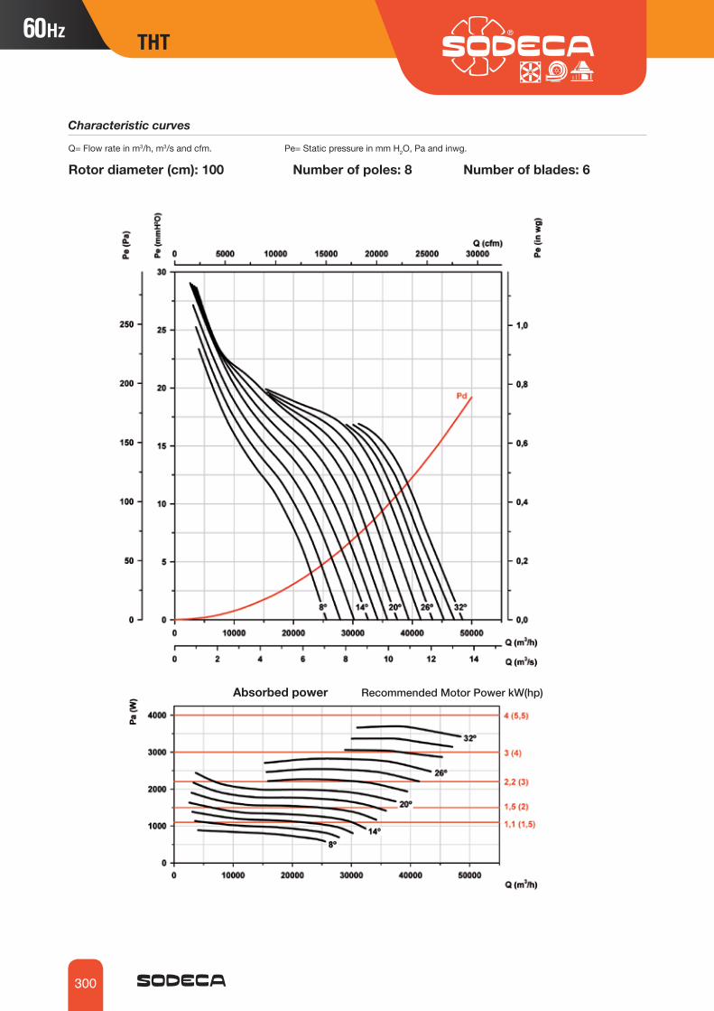
300
Rotor diameter (cm): 100 Number of poles: 8 Number of blades: 6 Q= Flow rate in m3/h, m3/s and cfm. Pe= Static pressure in mm H2O, Pa and inwg.
Characteristic curves
Absorbed power Recommended Motor Power kW(hp)
THT

301
THT
Rotor diameter (cm): 125 Number of poles: 4 Number of blades: 3 Q= Flow rate in m3/h, m3/s and cfm. Pe= Static pressure in mm H2O, Pa and inwg.
Characteristic curves
Absorbed power Recommended Motor Power kW(hp)
THT

302
Rotor diameter (cm): 125 Number of poles: 4 Number of blades: 6 Q= Flow rate in m3/h, m3/s and cfm. Pe= Static pressure in mm H2O, Pa and inwg.
Characteristic curves
Absorbed power Recommended Motor Power kW(hp)
THT

303
THT
Rotor diameter (cm): 125 Number of poles: 4 Number of blades: 9 Q= Flow rate in m3/h, m3/s and cfm. Pe= Static pressure in mm H2O, Pa and inwg.
Characteristic curves
Absorbed power Recommended Motor Power kW(hp)
THT

304
Rotor diameter (cm): 125 Number of poles: 6 Number of blades: 3 Q= Flow rate in m3/h, m3/s and cfm. Pe= Static pressure in mm H2O, Pa and inwg.
Characteristic curves
Absorbed power Recommended Motor Power kW(hp)
THT

305
THT
Rotor diameter (cm): 125 Number of poles: 6 Number of blades: 6 Q= Flow rate in m3/h, m3/s and cfm. Pe= Static pressure in mmH2O, Pa and inwg.
Characteristic curves
Absorbed power Recommended Motor Power kW(hp)
THT

306
Rotor diameter (cm): 125 Number of poles: 6 Number of blades: 9 Q= Flow rate in m3/h, m3/s and cfm. Pe= Static pressure in mmH2O, Pa and inwg.
Characteristic curves
Absorbed power Recommended Motor Power kW(hp)
THT

307
THT
Rotor diameter (cm): 140 Number of poles: 6 Number of blades: 3 Q= Flow rate in m3/h, m3/s and cfm. Pe= Static pressure in mmH2O, Pa and inwg.
Characteristic curves
Absorbed power Recommended Motor Power kW(hp)
THT

308
Rotor diameter (cm): 140 Number of poles: 6 Number of blades: 6 Q= Flow rate in m3/h, m3/s and cfm. Pe= Static pressure in mmH2O, Pa and inwg.
Characteristic curves
Absorbed power Recommended Motor Power kW(hp)
THT

309
THT
Rotor diameter (cm): 140 Number of poles: 6 Number of blades: 9 Q= Flow rate in m3/h, m3/s and cfm. Pe= Static pressure in mmH2O, Pa and inwg.
Characteristic curves
Absorbed power Recommended Motor Power kW(hp)
THT

310
Rotor diameter (cm): 140 Number of poles: 8 Number of blades: 3 Q= Flow rate in m3/h, m3/s and cfm. Pe= Static pressure in mmH2O, Pa and inwg.
Characteristic curves
Absorbed power Recommended Motor Power kW(hp)
THT

311
THT
Rotor diameter (cm): 140 Number of poles: 8 Number of blades: 6 Q= Flow rate in m3/h, m3/s and cfm. Pe= Static pressure in mmH2O, Pa and inwg.
Characteristic curves
Absorbed power Recommended Motor Power kW(hp)
THT

312
Rotor diameter (cm): 140 Number of poles: 8 Number of blades: 9Q= Flow rate in m3/h, m3/s and cfm. Pe= Static pressure in mmH2O, Pa and inwg.
Characteristic curves
Absorbed power Recommended Motor Power kW(hp)
THT
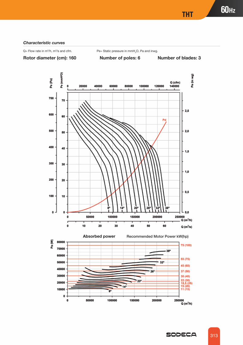
313
THT
Rotor diameter (cm): 160 Number of poles: 6 Number of blades: 3Q= Flow rate in m3/h, m3/s and cfm. Pe= Static pressure in mmH2O, Pa and inwg.
Characteristic curves
Absorbed power Recommended Motor Power kW(hp)
THT

314
Rotor diameter (cm): 160 Number of poles: 6 Number of blades: 6 Q= Flow rate in m3/h, m3/s and cfm. Pe= Static pressure in mmH2O, Pa and inwg.
Characteristic curves
Absorbed power Recommended Motor Power kW(hp)
THT
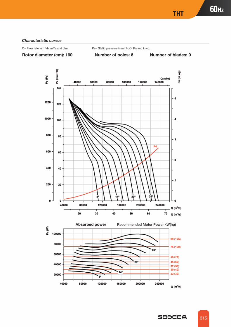
315
THT
Rotor diameter (cm): 160 Number of poles: 6 Number of blades: 9Q= Flow rate in m3/h, m3/s and cfm. Pe= Static pressure in mmH2O, Pa and inwg.
Characteristic curves
Absorbed power Recommended Motor Power kW(hp)
THT

316
Rotor diameter (cm): 160 Number of poles: 8 Number of blades: 3 Q= Flow rate in m3/h, m3/s and cfm. Pe= Static pressure in mmH2O, Pa and inwg.
Characteristic curves
Absorbed power Recommended Motor Power kW(hp)
THT

317
THT
Rotor diameter (cm): 160 Number of poles: 8 Number of blades: 6 Q= Flow rate in m3/h, m3/s and cfm. Pe= Static pressure in mmH2O, Pa and inwg.
Characteristic curves
Absorbed power Recommended Motor Power kW(hp)
THT

318
Rotor diameter (cm): 160 Number of poles: 8 Number of blades: 9 Q= Flow rate in m3/h, m3/s and cfm. Pe= Static pressure in mmH2O, Pa and inwg.
Characteristic curves
Absorbed power Recommended Motor Power kW(hp)
THT

319
THT THT/IMP
Order code
THT/IMP O UNI 38 2/4T 1.5 F-400 60Hz
THT/IMP 400 ºC/2h and 300 ºC/2h long range one-way or reversible jet fans
300 ºC/2h and 400 ºC/2h long range one-way or reversible jet fans with a circular (THT/IMP-C), octagonal (THT/IMP-L) or octagonal painted (THT/IMP-O) design
Fan:• One-way or reversible fan unit including fan, silencers, deflectors and
support, approved for smoke extraction in accordance with standard EN 12101-3, with certification no.: 0370-CPR-0394
• Adjustable rotors made of cast aluminium and designed to produce great thrusts.
• Anti-contact protective grille pursuant to standard UNE‐EN ISO 12499.• Deflector to increase the air range on the impulsion side. Reversible
models are fitted with deflectors on both sides.• High attenuation silencers with thermal and acoustic insulation.• IAT series safety switch built into the fan (THT/IMP-L and THT/ IMP-O)
or on request (THT/IMP-C).• Air direction from Motor to Impeller or 100 % reversible.• THT/IMP-C: Circular casing in painted sheet steel.• THT/IMP-L: Galvanised sheet steel casing.• THT/IMP-O: Painted steel casing.• THT/IMP-LS: Short length galvanised sheet steel casing.
Motor:• Class H motors, S1 continuous operation
and S2 emergency use, with ball bearings, IP55 protection and 2 speeds.
• Multi voltage motor, special design valid for 220/380V 60Hz, 254/440V 60Hz, 265/460V 60Hz, 277/480V 60Hz.
• Maximum temperature of air to be carried: S1 continuous operation -20 ºC +40 ºC, S2 operation 300 ºC/2h and 400 ºC/2h.
Finish: • Anti-corrosive finish of polyester resin
polymerised at 190 ºC, previously degreased with phosphate-free nanotechnological treatment (THT/IMP-C, THT/IMP-O) or with a galvanised sheet steel anticorrosive finish (THT/IMP-L).
On request:• Thrust features different from those
indicated.• Version for outdoor operation in the fire
risk zone (see HCT/IMP series).
Deflector for increasing range
0370-CPR-0394
Number of motor poles2=3500 r/min. 60 Hz4=1680 r/min. 60 Hz6=1080 r/min. 60 Hz8=900 r/min. 60 Hz12=750 r/min. 60 Hz
Rotor diameter in cm
THT/IMP: Large range jet fans
T= Three-phase
F-300: Approval.Tested for 300 ºC/2h.F-400: 400 ºC/2h approved
Motor power (hp)
DesignC: Circular casingO: Painted casingL: Galvanised sheet steel casing.LS: Small-sized casing
Airflow directionUNI: One-wayREV: Reversible
THT/IMP-L
THT/IMP-LS
THT/IMP-C
THT/IMP-O
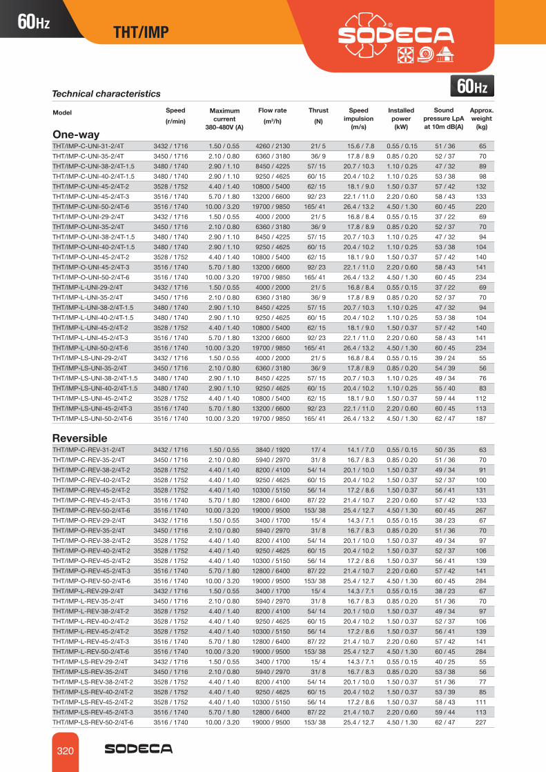
320
THT/IMP
Technical characteristicsSpeed(r/min)
Model Maximum current
380-480V (A)
Installed power(kW)
Thrust(N)
Sound pressure LpA at 10m dB(A)
Approx. weight
(kg)
Flow rate(m3/h)
Speedimpulsion
(m/s)One-wayTHT/IMP-C-UNI-31-2/4T 3432 / 1716 1.50 / 0.55 4260 / 2130 21/ 5 15.6 / 7.8 0.55 / 0.15 51 / 36 65THT/IMP-C-UNI-35-2/4T 3450 / 1716 2.10 / 0.80 6360 / 3180 36/ 9 17.8 / 8.9 0.85 / 0.20 52 / 37 70THT/IMP-C-UNI-38-2/4T-1.5 3480 / 1740 2.90 / 1.10 8450 / 4225 57/ 15 20.7 / 10.3 1.10 / 0.25 47 / 32 89THT/IMP-C-UNI-40-2/4T-1.5 3480 / 1740 2.90 / 1.10 9250 / 4625 60/ 15 20.4 / 10.2 1.10 / 0.25 53 / 38 98THT/IMP-C-UNI-45-2/4T-2 3528 / 1752 4.40 / 1.40 10800 / 5400 62/ 15 18.1 / 9.0 1.50 / 0.37 57 / 42 132THT/IMP-C-UNI-45-2/4T-3 3516 / 1740 5.70 / 1.80 13200 / 6600 92/ 23 22.1 / 11.0 2.20 / 0.60 58 / 43 133THT/IMP-C-UNI-50-2/4T-6 3516 / 1740 10.00 / 3.20 19700 / 9850 165/ 41 26.4 / 13.2 4.50 / 1.30 60 / 45 220THT/IMP-O-UNI-29-2/4T 3432 / 1716 1.50 / 0.55 4000 / 2000 21/ 5 16.8 / 8.4 0.55 / 0.15 37 / 22 69THT/IMP-O-UNI-35-2/4T 3450 / 1716 2.10 / 0.80 6360 / 3180 36/ 9 17.8 / 8.9 0.85 / 0.20 52 / 37 70THT/IMP-O-UNI-38-2/4T-1.5 3480 / 1740 2.90 / 1.10 8450 / 4225 57/ 15 20.7 / 10.3 1.10 / 0.25 47 / 32 94THT/IMP-O-UNI-40-2/4T-1.5 3480 / 1740 2.90 / 1.10 9250 / 4625 60/ 15 20.4 / 10.2 1.10 / 0.25 53 / 38 104THT/IMP-O-UNI-45-2/4T-2 3528 / 1752 4.40 / 1.40 10800 / 5400 62/ 15 18.1 / 9.0 1.50 / 0.37 57 / 42 140THT/IMP-O-UNI-45-2/4T-3 3516 / 1740 5.70 / 1.80 13200 / 6600 92/ 23 22.1 / 11.0 2.20 / 0.60 58 / 43 141THT/IMP-O-UNI-50-2/4T-6 3516 / 1740 10.00 / 3.20 19700 / 9850 165/ 41 26.4 / 13.2 4.50 / 1.30 60 / 45 234THT/IMP-L-UNI-29-2/4T 3432 / 1716 1.50 / 0.55 4000 / 2000 21/ 5 16.8 / 8.4 0.55 / 0.15 37 / 22 69THT/IMP-L-UNI-35-2/4T 3450 / 1716 2.10 / 0.80 6360 / 3180 36/ 9 17.8 / 8.9 0.85 / 0.20 52 / 37 70THT/IMP-L-UNI-38-2/4T-1.5 3480 / 1740 2.90 / 1.10 8450 / 4225 57/ 15 20.7 / 10.3 1.10 / 0.25 47 / 32 94THT/IMP-L-UNI-40-2/4T-1.5 3480 / 1740 2.90 / 1.10 9250 / 4625 60/ 15 20.4 / 10.2 1.10 / 0.25 53 / 38 104THT/IMP-L-UNI-45-2/4T-2 3528 / 1752 4.40 / 1.40 10800 / 5400 62/ 15 18.1 / 9.0 1.50 / 0.37 57 / 42 140THT/IMP-L-UNI-45-2/4T-3 3516 / 1740 5.70 / 1.80 13200 / 6600 92/ 23 22.1 / 11.0 2.20 / 0.60 58 / 43 141THT/IMP-L-UNI-50-2/4T-6 3516 / 1740 10.00 / 3.20 19700 / 9850 165/ 41 26.4 / 13.2 4.50 / 1.30 60 / 45 234THT/IMP-LS-UNI-29-2/4T 3432 / 1716 1.50 / 0.55 4000 / 2000 21/ 5 16.8 / 8.4 0.55 / 0.15 39 / 24 55THT/IMP-LS-UNI-35-2/4T 3450 / 1716 2.10 / 0.80 6360 / 3180 36/ 9 17.8 / 8.9 0.85 / 0.20 54 / 39 56THT/IMP-LS-UNI-38-2/4T-1.5 3480 / 1740 2.90 / 1.10 8450 / 4225 57/ 15 20.7 / 10.3 1.10 / 0.25 49 / 34 76THT/IMP-LS-UNI-40-2/4T-1.5 3480 / 1740 2.90 / 1.10 9250 / 4625 60/ 15 20.4 / 10.2 1.10 / 0.25 55 / 40 83THT/IMP-LS-UNI-45-2/4T-2 3528 / 1752 4.40 / 1.40 10800 / 5400 62/ 15 18.1 / 9.0 1.50 / 0.37 59 / 44 112THT/IMP-LS-UNI-45-2/4T-3 3516 / 1740 5.70 / 1.80 13200 / 6600 92/ 23 22.1 / 11.0 2.20 / 0.60 60 / 45 113THT/IMP-LS-UNI-50-2/4T-6 3516 / 1740 10.00 / 3.20 19700 / 9850 165/ 41 26.4 / 13.2 4.50 / 1.30 62 / 47 187 Reversible THT/IMP-C-REV-31-2/4T 3432 / 1716 1.50 / 0.55 3840 / 1920 17/ 4 14.1 / 7.0 0.55 / 0.15 50 / 35 63THT/IMP-C-REV-35-2/4T 3450 / 1716 2.10 / 0.80 5940 / 2970 31/ 8 16.7 / 8.3 0.85 / 0.20 51 / 36 70THT/IMP-C-REV-38-2/4T-2 3528 / 1752 4.40 / 1.40 8200 / 4100 54/ 14 20.1 / 10.0 1.50 / 0.37 49 / 34 91THT/IMP-C-REV-40-2/4T-2 3528 / 1752 4.40 / 1.40 9250 / 4625 60/ 15 20.4 / 10.2 1.50 / 0.37 52 / 37 100THT/IMP-C-REV-45-2/4T-2 3528 / 1752 4.40 / 1.40 10300 / 5150 56/ 14 17.2 / 8.6 1.50 / 0.37 56 / 41 131THT/IMP-C-REV-45-2/4T-3 3516 / 1740 5.70 / 1.80 12800 / 6400 87/ 22 21.4 / 10.7 2.20 / 0.60 57 / 42 133THT/IMP-C-REV-50-2/4T-6 3516 / 1740 10.00 / 3.20 19000 / 9500 153/ 38 25.4 / 12.7 4.50 / 1.30 60 / 45 267THT/IMP-O-REV-29-2/4T 3432 / 1716 1.50 / 0.55 3400 / 1700 15/ 4 14.3 / 7.1 0.55 / 0.15 38 / 23 67THT/IMP-O-REV-35-2/4T 3450 / 1716 2.10 / 0.80 5940 / 2970 31/ 8 16.7 / 8.3 0.85 / 0.20 51 / 36 70THT/IMP-O-REV-38-2/4T-2 3528 / 1752 4.40 / 1.40 8200 / 4100 54/ 14 20.1 / 10.0 1.50 / 0.37 49 / 34 97THT/IMP-O-REV-40-2/4T-2 3528 / 1752 4.40 / 1.40 9250 / 4625 60/ 15 20.4 / 10.2 1.50 / 0.37 52 / 37 106THT/IMP-O-REV-45-2/4T-2 3528 / 1752 4.40 / 1.40 10300 / 5150 56/ 14 17.2 / 8.6 1.50 / 0.37 56 / 41 139THT/IMP-O-REV-45-2/4T-3 3516 / 1740 5.70 / 1.80 12800 / 6400 87/ 22 21.4 / 10.7 2.20 / 0.60 57 / 42 141THT/IMP-O-REV-50-2/4T-6 3516 / 1740 10.00 / 3.20 19000 / 9500 153/ 38 25.4 / 12.7 4.50 / 1.30 60 / 45 284THT/IMP-L-REV-29-2/4T 3432 / 1716 1.50 / 0.55 3400 / 1700 15/ 4 14.3 / 7.1 0.55 / 0.15 38 / 23 67THT/IMP-L-REV-35-2/4T 3450 / 1716 2.10 / 0.80 5940 / 2970 31/ 8 16.7 / 8.3 0.85 / 0.20 51 / 36 70THT/IMP-L-REV-38-2/4T-2 3528 / 1752 4.40 / 1.40 8200 / 4100 54/ 14 20.1 / 10.0 1.50 / 0.37 49 / 34 97THT/IMP-L-REV-40-2/4T-2 3528 / 1752 4.40 / 1.40 9250 / 4625 60/ 15 20.4 / 10.2 1.50 / 0.37 52 / 37 106THT/IMP-L-REV-45-2/4T-2 3528 / 1752 4.40 / 1.40 10300 / 5150 56/ 14 17.2 / 8.6 1.50 / 0.37 56 / 41 139THT/IMP-L-REV-45-2/4T-3 3516 / 1740 5.70 / 1.80 12800 / 6400 87/ 22 21.4 / 10.7 2.20 / 0.60 57 / 42 141THT/IMP-L-REV-50-2/4T-6 3516 / 1740 10.00 / 3.20 19000 / 9500 153/ 38 25.4 / 12.7 4.50 / 1.30 60 / 45 284THT/IMP-LS-REV-29-2/4T 3432 / 1716 1.50 / 0.55 3400 / 1700 15/ 4 14.3 / 7.1 0.55 / 0.15 40 / 25 55THT/IMP-LS-REV-35-2/4T 3450 / 1716 2.10 / 0.80 5940 / 2970 31/ 8 16.7 / 8.3 0.85 / 0.20 53 / 38 56THT/IMP-LS-REV-38-2/4T-2 3528 / 1752 4.40 / 1.40 8200 / 4100 54/ 14 20.1 / 10.0 1.50 / 0.37 51 / 36 77THT/IMP-LS-REV-40-2/4T-2 3528 / 1752 4.40 / 1.40 9250 / 4625 60/ 15 20.4 / 10.2 1.50 / 0.37 53 / 39 85THT/IMP-LS-REV-45-2/4T-2 3528 / 1752 4.40 / 1.40 10300 / 5150 56/ 14 17.2 / 8.6 1.50 / 0.37 58 / 43 111THT/IMP-LS-REV-45-2/4T-3 3516 / 1740 5.70 / 1.80 12800 / 6400 87/ 22 21.4 / 10.7 2.20 / 0.60 59 / 44 113THT/IMP-LS-REV-50-2/4T-6 3516 / 1740 10.00 / 3.20 19000 / 9500 153/ 38 25.4 / 12.7 4.50 / 1.30 62 / 47 227

321
THT/IMP THT/IMP
Dimensions mm
Model ØA ØB C L Ød E (UNI) E (REV) H X ZTHT/IMP-C-31 315 415 320 700 10 1956 2000 220 345 275THT/IMP-C-35 355 460 325 700 12 1960 2005 250 346 300THT/IMP-C-38 380 415 340 1000 12 2570 2620 225 530 517THT/IMP-C-40 410 510 340 950 12 2485 2540 280 376 340THT/IMP-C-45 460 630 360 950 12 2500 2554 355 396 440
C: Circular casing
Model ØA ØB C L Ød E(UNI) E(REV) H H1- X X1 X2 Z Z1THT/IMP-C-50 514 710 450 1100 12 2895 2950 498 80 518 320 700 380 370

322
THT/IMP
For use in garages
P-400
Accessories
INT IAT C2VCABLE BOX AET CENTRAL CO VSD
Installation of jet fans for immersed operation in fire risk zones
O: Painted casingL: Galvanised sheet steel casing.LS: Small-sized casing
A B C ød E (UNI) E (REV) L X X1 Z Z1THT/IMP-LS-29 319.5 324 479 12x26 1410 1610 1200 400 167 580 610THT/IMP-L-29 319.5 324 479 12x26 2210 2410 2000 400 167 580 610THT/IMP-O-29 319.5 324 479 12x26 2210 2410 2000 400 167 580 610THT/IMP-LS-35 383 386 523 12x26 1410 1610 1200 400 167 614 644THT/IMP-L-35 383 386 523 12x26 2210 2410 2000 400 167 614 644THT/IMP-O-35 383 386 523 12x26 2210 2410 2000 400 167 614 644THT/IMP-LS-38 406 409 550 12x26 1410 1610 1200 400 170 640 670THT/IMP-L-38 406 409 550 12x26 2210 2410 2000 400 170 640 670THT/IMP-O-38 406 409 550 12x26 2210 2410 2000 400 170 640 670THT/IMP-LS-40 436 439 582 12x26 1410 1610 1200 400 170 670 700THT/IMP-L-40 436 439 582 12x26 2210 2410 2000 400 170 670 700THT/IMP-O-40 436 439 582 12x26 2210 2410 2000 400 170 670 700THT/IMP-LS-45 486 489 630 12x26 1410 1610 1200 400 170 724 754THT/IMP-L-45 486 489 630 12x26 2210 2410 2000 400 170 724 754THT/IMP-O-45 486 489 630 12x26 2210 2410 2000 400 170 724 754THT/IMP-LS-50 546 549 742 12x26 1445 1675 1200 580 255 778 808THT/IMP-L-50 546 549 742 12x26 2245 2475 2000 580 255 778 808THT/IMP-O-50 546 549 742 12x26 2245 2475 2000 580 255 778 808
LS:
L

323
THT/IMP
CI
Order code
CI 50 4T F-300
Technical characteristics
60Hz
CI
External junction box.Support feet
Long-range 300 ºC/2h and 400 ºC/2h centrifugal induction jet fans for use in fire risk zones with a low profile.
Long-range 300 ºC/2h and 400 ºC/2h centrifugal induction jet fans for use in fire risk zones with a low profile.
Fan:• Sheet steel casing.• Impeller with reaction blades in extremely robust sheet steel.• External junction box.• Support feet included.
Motor:• Class H motors, S1 continuous operation
and S2 emergency use, with ball bearings, IP55 protection and with 1 or 2 speeds, depending on model.
• Multi voltage motor, special design valid for 220/380V 60Hz, 254/440V 60Hz, 265/460V 60Hz, 277/480V 60Hz
• Maximum temperature of air to be carried: S1 continuous operation -20 ºC +40 ºC, S2 operation 300 ºC/2h and 400 ºC/2h.
Finish:• Anti-corrosive finish of polyester resin po-
lymerised at 190 ºC, previously degreased with phosphate-free nanotechnological treatment.
On request:• Version for outdoor operation in the fire risk
zone (see CI-CO series)
0370-CPR-0715
Number of motor poles2=3500 r/min. 60 Hz4=1680 r/min. 60 Hz6=1080 r/min. 60 Hz8=900 r/min. 60 Hz12=750 r/min. 60 Hz
Rotor diameter in cm
Long-range 300 ºC/2h and 400 ºC/2h centrifugal induction jet fans for use in fire risk zones with a low profile.
T= Three-phase F-300: Approval.Tested for 300 ºC/2h
F-400: 400 ºC/2h approved
Dimensions mm
Model A B C V2 V1 X1 X2 KxnCI-50-F300 1240 840 272.5 741.5 524.5 413 477 12x26CI-50-F400 1240 840 261.5 741.5 524.5 413 477 12x26CI-75-F300 1778 1040 311 1143 662 494 596 12x26CI-75-F400 1778 1040 299 1143 662 494 596 12x26CI-100 F-300 1778 1040 323 1143 662 494 596 12x26CI-100 F-400 1778 1040 323 1143 662 494 596 12x26
Accessories
INT IAT C2VCABLE BOX AET CENTRAL CO VSD
220-277V 380-480V
Speed(r/min)
Model Maximum admissible current (A)
Flow rate (m3/h)
Sound pres-sure LpA
at 1m dB(A)
Approx. weight
(kg)
CI-50-4T 1674 5.00 2.90 6050 50 1.20 78 83CI-50-4/8T 1674/780 2.90 / 1.20 6050 / 3020 50 / 13 1.20 / 0.30 78/63 83CI-75-4T 1740 9.00 5.20 8080 75 2,20 85 139CI-75-4/8T 1740/876 5.20 / 2.05 8080 / 4040 75 / 19 2.20 / 0.37 85/70 139CI-100-4T 1734 9.90 5.70 9340 100 2.40 89 141CI-100-4/8T 1734/858 5.70 / 2.20 9340 / 4670 100 / 25 2.40 / 0.55 89/14 141
Installed power(kW)
Thrust(N)

324
HTMF
HTMF 56 4T 2 F-400
Number of motor poles2=3500 r/min. 60 Hz4=1680 r/min. 60 Hz6=1080 r/min. 60 Hz8=900 r/min. 60 Hz12=750 r/min. 60 Hz
Rotor diameter in cm
HTMF: 400 ºC/2h and 300 ºC/2h roof-mounted multi-functional extractor fans
T= Three-phase F-300: 300 ºC/2h approvedF-400: 400 ºC/2h approved
Motorpower (hp)
60Hz
400 ºC/2h (F-400) and 300 ºC/2h (F-300) rated roof-mounted multifunctional extractor fansHTMF400 ºC/2h rated roof-mounted multifunctional extractor fans for work in fire risk zones, designed for smoke extraction in industrial or similar buildings
Fan:• Painted, galvanised sheet steel support base.• Cast aluminium orientable rotors.• Anti-contact protective grille pursuant to standard
UNE‐EN ISO 12499.• Painted, galvanised sheet steel rain cap, with natural air outlet.
Approved based on standard EN 12101-3, with certificate no. 0370-CPR-0544.
Motor:• Class H motors, S1 continuous operation
and S2 emergency use, with ball bearings, IP55 protection and with 1 or 2 speeds, depending on model.
• Multi voltage motor, special design valid for 220/380V 60Hz, 254/440V 60Hz, 265/460V 60Hz, 277/480V 60Hz
• Maximum temperature of air to be carried: S1 continuous operation -20 ºC +40 ºC, S2 operation 300 ºC/2h, 400 ºC/2h.
Finish: • Anti-corrosive finish of polyester resin
polymerised at 190 ºC, previously degreased with phosphate-free nanotechnological treatment.
Order code
Technical characteristics
0370-CPR-0544
HTMF-56-4T-1 1716 3.80 2.20 0.75 10545 62 59 65HTMF-56-4T-1.5 1704 4.70 2.70 1.10 11400 63 60 71HTMF-56-4/8T-1.5 1728 / 852 2.90 / 1.40 1.10 / 0.25 11400 / 5700 63 / 48 60 / 45 75HTMF-56-6T-0.75 1116 3.30 1.90 0.55 8170 51 49 64HTMF-63-4T-1.5 1704 4.70 2.70 1.10 13870 65 62 83HTMF-63-4/8T-1,5 1728 / 852 2.90 / 1.40 1.10 / 0.25 13870 / 6935 65 / 50 62 / 47 87HTMF-63-4T-2 1710 6.60 3.80 1.50 15485 66 63 85HTMF-63-4/8T-2 1698 / 858 3.60 / 1.50 1.50 / 0.30 15485 / 7742 66 / 51 63 / 48 90HTMF-63-4T-3 1722 9.20 5.30 2.20 17955 67 64 90HTMF-63-4/8T-3 1698 / 858 5.20 / 1.90 2.20 / 0.45 17955 / 8977 67 / 52 64 / 49 103HTMF-63-6T-0.75 1116 3.30 1.90 0.55 10260 56 54 76HTMF-63-6T-1 1128 4.40 2.60 0.75 11305 57 55 85HTMF-71-4T-2 1710 6.60 3.80 1.50 16150 69 66 90HTMF-71-4/8T-2 1698 / 858 3.60 / 1.50 1.50 / 0.30 16150 / 8075 69 / 54 66 / 51 96HTMF-71-4T-3 1722 9.20 5.30 2.20 18430 71 68 96HTMF-71-4/8T-3 1698 / 858 5.20 / 1.90 2.20 / 0.45 18430 / 9215 71 / 56 68 / 53 109HTMF-71-4T-4 1716 11.40 6.60 3.00 22610 72 69 100HTMF-71-4/8T-4 1704 / 846 6.90 / 2.30 3.00 / 0.60 22610 / 11305 72 / 57 69 / 54 111
Model Speed Maximum admissible current (A)
Installed power
Maximum flow rate
Sound pressure (1) level dB(A)
Approx. weight
(r/min) 220-277V 380-480V (kW) (m3/h) Intake Discharge (kg)

325
HTMF HTMF
Technical characteristics
Model Speed Maximum admissible current (A)
Installed power
Maximum flow rate
Sound pressure (1) level dB(A)
Approx. weight
(r/min) 220-277V 380-480V (kW) (m3/h) Intake Discharge (kg)
(1) The noise level values are pressures in dB(A) measured at a distance of 6 metres in a free field.
HTMF-71-6T-1 1128 4.40 2.60 0.75 13205 58 56 90HTMF-71-6T-1.5 1134 6.40 3.70 1.10 16245 59 57 92HTMF-80-4T-4 1716 11.40 6.60 3.00 27600 73 70 123HTMF-80-4/8T-4 1704 / 846 6.90 / 2.30 3.00 / 0.60 27600 / 13800 73 / 58 70 / 55 134HTMF-80-4T-5.5 1728 8.40 4.00 30176 74 71 134HTMF-80-4/8T-5,5 1740 / 864 9.40 / 3.50 4.00 / 0.80 30176 / 15088 74 / 59 71 / 56 138HTMF-80-6T-1.5 1134 6.40 3.70 1.10 19412 62 60 115HTMF-80-6T-2 1134 7.40 4.30 1.50 22172 63 61 120HTMF-80-6T-3 1140 10.30 5.90 2.20 24932 64 62 134HTMF-80-8T-1 852 4.80 2.80 0.75 16376 61 60 132HTMF-90-4T-5.5 1728 8.40 4.00 35052 79 76 156HTMF-90-4/8T-5,5 1740 / 864 9.40 / 3.50 4.00 / 0.80 35052 / 17526 79 / 64 76 / 61 160HTMF-90-4T-7.5 1716 11.50 5.50 38456 81 78 161HTMF-90-4/8T-7,5 1746 / 870 12.80 / 4.60 5.50 / 1.10 38456 / 19228 81 / 66 78 / 63 207HTMF-90-4T-10 1752 17.70 7.50 41308 82 79 225HTMF-90-4/8T-9 1746 / 870 15.50 / 5.50 6.70 / 1.50 41308 / 20654 82 / 67 79 / 64 215HTMF-90-6T-3 1140 10.30 5.90 2.20 29256 68 66 156HTMF-90-6/12T-3 1128 / 564 5.60 / 2.20 2.20 / 0.37 29256 / 14628 68 / 53 66 / 51 161HTMF-90-6T-4 1134 15.00 8.70 3.00 32016 69 67 164HTMF-90-6/12T-4 1164 / 570 8.90 / 3.50 3.00 / 0.55 32016 / 16008 69 / 54 67 / 52 188HTMF-90-8T-1 852 4.80 2.80 0.75 17020 61 60 154HTMF-90-8T-2 840 9.00 5.20 1.50 19596 63 62 158HTMF-100-4T-7.5 1716 11.50 5.50 40756 84 81 185HTMF-100-4/8T-7,5 1746 / 870 12.80 / 4.60 5.50 / 1.10 40756 / 20378 84 / 69 81 / 66 231HTMF-100-4T-10 1752 17.70 7.50 47564 85 82 249HTMF-100-4/8T-9 1746 / 870 15.50 / 5.50 6.70 / 1.50 44528 / 22264 84 / 69 81 / 66 239HTMF-100-4T-15 1746 23.00 11.00 51336 86 83 268HTMF-100-4/8T-14 1764 / 870 23.20 / 8.70 11.00 / 2.80 48300 / 24150 85 / 70 82 / 67 280HTMF-100-6T-3 1140 10.30 5.90 2.20 32476 74 72 180HTMF-100-6/12T-3 1128 / 564 5.60 / 2.20 2.20 / 0.37 32476 / 16238 74 / 59 72 / 57 185HTMF-100-6T-4 1134 15.00 8.70 3.00 35420 75 73 188HTMF-100-6/12T-4 1164 / 570 8.90 / 3.50 3.00 / 0.55 35420 / 17710 75 / 60 73 / 58 212HTMF-100-6T-5.5 1164 11.00 4.00 40020 76 74 212HTMF-100-6/12T-5.5 1164 / 576 11.30 / 4.20 4.00 / 0.65 40020 / 20010 76 / 61 74 / 59 239HTMF-100-8T-3 846 13.20 7.60 2.20 26404 69 68 189HTMF-100-8T-4 852 15.60 9.00 3.00 28704 70 69 249HTMF-THT-125-4T/3/-10 1752 13.90 7.50 55250 75 72 333HTMF-THT-125-4T/3/-15 1764 20.90 11.00 72150 76 73 372HTMF-THT-125-4T/3/-20 1758 27.90 15.00 83120 78 75 394HTMF-THT-125-4T/6/-15 1764 20.90 11.00 66800 76 73 388HTMF-THT-125-4T/6/-20 1758 27.90 15.00 72900 76 73 410HTMF-THT-125-4T/9/-20 1758 27.90 15.00 76310 75 72 425HTMF-THT-125-6T/6/-5.5 1164 11.00 4.00 47760 63 61 347HTMF-THT-125-6T/6/-7.5 1164 14.00 5.50 55600 63 61 384HTMF-THT-125-6T/6/-10 1170 14.80 7.50 66170 65 63 393HTMF-THT-125-6T/6/-15 1170 21.90 11.00 76380 67 65 415HTMF-THT-125-6T/9/-7.5 1164 14.00 5.50 50000 64 62 399HTMF-THT-125-6T/9/-10 1170 14.80 7.50 59340 64 62 408HTMF-THT-125-6T/9/-15 1170 21.90 11.00 71890 67 65 430HTMF-THT-125-6T/9/-20 1170 28.20 15.00 83660 70 68 475HTMF-THT-125-8T/6/-4 852 15.60 9.00 3.00 47510 56 55 384HTMF-THT-125-8T/6/-5.5 852 13.00 4.00 52770 58 57 404HTMF-THT-125-8T/6/-7.5 852 15.10 5.50 60410 60 59 416HTMF-THT-125-8T/6/-10 858 20.60 7.50 66030 61 60 424HTMF-THT-125-8T/9/-5.5 852 13.00 4.00 51330 58 57 419HTMF-THT-125-8T/9/-7.5 852 15.10 5.50 54480 61 60 431HTMF-THT-125-8T/9/-10 858 20.60 7.50 65660 63 62 439HTMF-THT-125-8T/9/-15 870 21.70 11.00 73870 64 63 445

326
HTMF
Values taken during intake with maximum flow rate Values taken during discharge with maximum flow rate
Acoustic characteristics
Sound power spectrum Lw(A) in dB(A) per Hz frequency band.
56-4-1 46 67 74 79 82 78 71 6056-4-1.5 47 68 75 80 83 79 72 6156-6-0.75 35 56 63 68 71 67 60 4956-8-1.5 32 53 60 65 68 64 57 4663-4-1.5 49 70 77 82 85 81 74 6363-4-2 50 71 78 83 86 82 75 6463-4-3 51 72 79 84 87 83 76 6563-6-0.75 40 61 68 73 76 72 65 5463-6-1 41 62 69 74 77 73 66 5563-8-1.5 34 55 62 67 70 66 59 4863-8-2 35 56 63 68 71 67 60 4963-8-3 36 57 64 69 72 68 61 5071-4-2 53 74 81 86 89 85 78 6771-4-3 55 76 83 88 91 87 80 6971-4-4 56 77 84 89 92 88 81 7071-6-1 42 63 70 75 78 74 67 5671-6-1.5 43 64 71 76 79 75 68 5771-8-2 38 59 66 71 74 70 63 5271-8-3 40 61 68 73 76 72 65 5471-8-4 41 62 69 74 77 73 66 5580-4-4 57 78 85 90 93 89 82 7180-4-5.5 58 79 86 91 94 90 83 7280-6-1.5 46 67 74 79 82 78 71 6080-6-2 47 68 75 80 83 79 72 6180-6-3 48 69 76 81 84 80 73 6280-8-1 45 66 73 78 81 77 70 5980-8-4 42 63 70 75 78 74 67 5680-8-5.5 43 64 71 76 79 75 68 5790-4-5.5 63 84 91 96 99 95 88 7790-4-7.5 65 86 93 98 101 97 90 7990-4-9 66 87 94 99 102 98 91 8090-4-10 66 87 94 99 102 98 91 8090-6-3 52 73 80 85 88 84 77 6690-6-4 53 74 81 86 89 85 78 6790-8-1 45 66 73 78 81 77 70 5990-8-2 47 68 75 80 83 79 72 6190-8-5.5 48 69 76 81 84 80 73 6290-8-7.5 50 71 78 83 86 82 75 6490-8-9 51 72 79 84 87 83 76 6590-12-3 37 58 65 70 73 69 62 5190-12-4 38 59 66 71 74 70 63 52100-4-7.5 68 89 96 101 104 100 93 82100-4-9 68 89 96 101 104 100 93 82100-4-10 69 90 97 102 105 101 94 83100-4-14 69 90 97 102 105 101 94 83100-4-15 70 91 98 103 106 102 95 84100-6-3 58 79 86 91 94 90 83 72100-6-4 59 80 87 92 95 91 84 73100-6-5.5 60 81 88 93 96 92 85 74100-8-3 53 74 81 86 89 85 78 67100-8-4 54 75 82 87 90 86 79 68100-8-7.5 53 74 81 86 89 85 78 67100-8-9 53 74 81 86 89 85 78 67100-8-14 54 75 82 87 90 86 79 68100-12-3 43 64 71 76 79 75 68 57100-12-4 44 65 72 77 80 76 69 58100-12-5.5 45 66 73 78 81 77 70 59125-4T/3-10 66 73 84 94 95 90 82 78125-4T/3-15 67 74 85 95 96 91 83 79125-4T/3-20 69 76 87 97 98 93 85 81125-4T/6-15 63 72 87 94 97 91 85 81125-4T/6-20 63 72 87 94 97 91 85 81125-4T/9-20 62 71 87 93 95 89 84 80125-6T/6-5,5 56 66 78 81 83 79 68 64125-6T/6-7,5 56 66 78 81 83 79 68 64125-6T/6-10 58 68 80 83 85 81 70 66125-6T/6-15 60 70 82 85 87 83 72 68125-6T/9-7,5 54 65 79 83 83 81 70 66125-6T/9-10 54 65 79 83 83 81 70 66125-6T/9-15 57 68 82 86 86 84 73 69125-6T/9-20 60 71 85 89 89 87 76 72125-8T/6-4 50 59 70 75 75 69 58 54125-8T/6-5.5 52 61 72 77 77 71 60 56125-8T/6-7.5 54 63 74 79 79 73 62 58125-8T/6-10 55 64 75 80 80 74 63 59125-8T/9-5.5 49 61 70 76 78 72 61 57125-8T/9-7.5 52 64 73 79 81 75 64 60125-8T/9-10 54 66 75 81 83 77 66 62125-8T/9-15 55 67 76 82 84 78 67 63
56-4-1 43 64 71 76 79 75 68 5756-4-1.5 44 65 72 77 80 76 69 5856-6-0.75 33 54 61 66 69 65 58 4756-8-1.5 29 50 57 62 65 61 54 4363-4-1.5 46 67 74 79 82 78 71 6063-4-2 47 68 75 80 83 79 72 6163-4-3 48 69 76 81 84 80 73 6263-6-0.75 38 59 66 71 74 70 63 5263-6-1 39 60 67 72 75 71 64 5363-8-1.5 31 52 59 64 67 63 56 4563-8-2 32 53 60 65 68 64 57 4663-8-3 33 54 61 66 69 65 58 4771-4-2 50 71 78 83 86 82 75 6471-4-3 52 73 80 85 88 84 77 6671-4-4 53 74 81 86 89 85 78 6771-6-1 40 61 68 73 76 72 65 5471-6-1.5 41 62 69 74 77 73 66 5571-8-2 35 56 63 68 71 67 60 4971-8-3 37 58 65 70 73 69 62 5171-8-4 38 59 66 71 74 70 63 5280-4-4 54 75 82 87 90 86 79 6880-4-5.5 55 76 83 88 91 87 80 6980-6-1.5 44 65 72 77 80 76 69 5880-6-2 45 66 73 78 81 77 70 5980-6-3 46 67 74 79 82 78 71 6080-8-1 44 65 72 77 80 76 69 5880-8-4 39 60 67 72 75 71 64 5380-8-5.5 40 61 68 73 76 72 65 5490-4-5.5 60 81 88 93 96 92 85 7490-4-7.5 62 83 90 95 98 94 87 7690-4-9 63 84 91 96 99 95 88 7790-4-10 63 84 91 96 99 95 88 7790-6-3 50 71 78 83 86 82 75 6490-6-4 51 72 79 84 87 83 76 6590-8-1 44 65 72 77 80 76 69 5890-8-2 46 67 74 79 82 78 71 6090-8-5.5 45 66 73 78 81 77 70 5990-8-7.5 47 68 75 80 83 79 72 6190-8-9 48 69 76 81 84 80 73 6290-12-3 35 56 63 68 71 67 60 4990-12-4 36 57 64 69 72 68 61 50100-4-7.5 65 86 93 98 101 97 90 79100-4-9 65 86 93 98 101 97 90 79100-4-10 66 87 94 99 102 98 91 80100-4-14 66 87 94 99 102 98 91 80100-4-15 67 88 95 100 103 99 92 81100-6-3 56 77 84 89 92 88 81 70100-6-4 57 78 85 90 93 89 82 71100-6-5.5 58 79 86 91 94 90 83 72100-8-3 52 73 80 85 88 84 77 66100-8-4 53 74 81 86 89 85 78 67100-8-7.5 50 71 78 83 86 82 75 64100-8-9 50 71 78 83 86 82 75 64100-8-14 51 72 79 84 87 83 76 65100-12-3 41 62 69 74 77 73 66 55100-12-4 42 63 70 75 78 74 67 56100-12-5.5 43 64 71 76 79 75 68 57125-4T/3-10 63 70 81 91 92 87 79 75125-4T/3-15 64 71 82 92 93 88 80 76125-4T/3-20 66 73 84 94 95 90 82 78125-4T/6-15 60 69 84 91 94 88 82 78125-4T/6-20 60 69 84 91 94 88 82 78125-4T/9-20 59 68 84 90 92 86 81 77125-6T/6-5,5 54 64 76 79 81 77 66 62125-6T/6-7,5 54 64 76 79 81 77 66 62125-6T/6-10 56 66 78 81 83 79 68 64125-6T/6-15 58 68 80 83 85 81 70 66125-6T/9-7,5 52 63 77 81 81 79 68 64125-6T/9-10 52 63 77 81 81 79 68 64125-6T/9-15 55 66 80 84 84 82 71 67125-6T/9-20 58 69 83 87 87 85 74 70125-8T/6-4 49 58 69 74 74 68 57 53125-8T/6-5.5 51 60 71 76 76 70 59 55125-8T/6-7.5 53 62 73 78 78 72 61 57125-8T/6-10 54 63 74 79 79 73 62 58125-8T/9-5.5 48 60 69 75 77 71 60 56125-8T/9-7.5 51 63 72 78 80 74 63 59125-8T/9-10 53 65 74 80 82 76 65 61125-8T/9-15 54 66 75 81 83 77 66 62
Model 63 125 250 500 1000 2000 4000 8000 Model 63 125 250 500 1000 2000 4000 8000

327
HTMF HTMF
Dimensions mm
Model A B C D F G H IHTMF-56 650 185 465 40 960 900 750 14HTMF-63 680 215 465 40 1092 1000 850 14HTMF-71 760 195 565 40 1120 1000 850 14HTMF-80 790 215 575 50 1252 1150 1000 14HTMF-90 910 232 678 50 1380 1150 1000 14HTMF-100 1055 252 803 50 1527 1250 1100 14HTMF-125 1170 310 859 50 1802 1600 1450 17
Sound pressure validation depending on distanceThe noise level may vary depending on the roof or tile structure.
RT
See accessories sectionAccessories
INT IAT C2VCABLE BOX AET CENTRAL CO VSD

328
Characteristic curvesQ= Flow rate in m3/h, m3/s and cfm. Pe= Static pressure in mmH2O, Pa and inwg.
HTMF-56
HTMF-71
HTMF-63
HTMF-80
HTMF

329
Characteristic curvesQ= Flow rate in m3/h, m3/s and cfm. Pe= Static pressure in mmH2O, Pa and inwg.
HTMF-90
HTMF-THT-125-4T/3
HTMF-100
HTMF-THT-125-4T/6/9
HTMF HTMF

330
Characteristic curvesQ= Flow rate in m3/h, m3/s and cfm. Pe= Static pressure in mmH2O, Pa and inwg.
HTMF
HTMF-THT-125-6T/6 HTMF-THT-125-6T/9

331
THT/ROOF 400 ºC/2h and 300 ºC/2h roof-mounted axial extractor fans with vertical air outlet
Roof-mounted axial extractor fans with vertical air outlet, for work in fire risk zones, designed for smoke extraction in industrial or similar buildings.
Fan:• Galvanised sheet steel support base with anti-corrosive treatment.• Cast aluminium orientable rotors.• Anti-contact protective grille pursuant to standard
UNE‐EN ISO 12499.• Anti-return hatch in aluminium sheet metal to prevent the entry
of water when the fan is not operating.• Approved in accordance with standard EN 12101-3. With
0370‐CPR‐0305 (F400) and 0370‐CPR‐0973 (F300) certifications.• Airflow direction from Motor to Impeller.
Motor:• Class H motors for S1 continuous
operation and S2 emergency use. With ball bearings and class IP55 protection.
• Multi voltage motor, special design valid for 220/380V 60Hz, 254/440V 60Hz, 265/460V 60Hz, 277/480V 60Hz
• Maximum temperature of air to be carried: S1 continuous operation ‐20 ºC +40 ºC. S2 operation, 300 ºC/2h, 400 ºC/2h.
Finish:• Anti-corrosive finish of polyester resin
polymerised at 190 ºC, previously degreased with phosphate-free nanotechnological treatment.
On request:• Extractor fans with 2-speed motors.• 2 and 8-pole fans depending on diameter.
Order code
THT/ROOF 56 4T 2 F400 60Hz
THT/ROOF 125 4T/9 24 F400 60Hz
THT/ROOF: 400 ºC/2h and 300 ºC/2h roof-mounted axial extractor fans with vertical air outlet
THT/ROOF: Extremely robust,roof-mounted axial extractor fans with vertical air outlet
From size 40 to size 100
Size 120
Rotordiameter in cm
Rotordiameter in cm
Number of motor polesT: Three-phase
Number of motor polesT: Three-phase
Numberof blades3 blades6 blades9 blades
Motor power(c.v.)
Motor power(c.v.)
F-300: Approval. Tested for 300 ºC/2h.F-400: 400 ºC/2h approved
F-300: Approval. Tested for 300 ºC/2h.F-400: 400 ºC/2h approved
0370-CPR-0897
Technical characteristics
THT/ROOF-40-4T-0.75 1704 2.90 1.70 0.55 32 4800 53.55 48.3 39THT/ROOF-40-6T-0.75 1116 3.30 1.90 0.55 32 3150 42 37.8 44THT/ROOF-45-4T-0.75 1704 2.90 1.70 0.55 36 7450 57.75 52.5 42THT/ROOF-45-6T-0.75 1116 3.30 1.90 0.55 30 4450 44.1 39.9 47THT/ROOF-50-4T-1 1716 3.80 2.20 0.75 28 9750 61.95 56.7 51THT/ROOF-50-6T-0.75 1116 3.30 1.90 0.55 32 7000 49.35 45.15 54THT/ROOF-56-4T-1 1716 3.80 2.20 0.75 22 11250 66.15 60.9 58THT/ROOF-56-4T-1.5 1704 4.70 2.70 1.10 30 13600 67.2 61.95 58THT/ROOF-56-4T-2 1710 6.60 3.80 1.50 36 15050 68.25 63 61THT/ROOF-56-6T-0.75 1116 3.30 1.90 0.55 38 10150 54.6 50.4 57THT/ROOF-63-4T-1.5 1704 4.70 2.70 1.10 20 17800 66.15 61.95 67THT/ROOF-63-4T-2 1710 6.60 3.80 1.50 24 19300 66.15 61.95 71THT/ROOF-63-4T-3 1722 9.20 5.30 2.20 32 22150 68.25 64.05 76THT/ROOF-63-4T-4 1716 11.40 6.60 3.00 38 24250 69.3 65.1 85THT/ROOF-63-6T-0.75 1116 3.30 1.90 0.55 28 13600 57.75 53.55 67
Model SpeedMaximum admissible
current (A)Installedpower
Angleinclination
blades
Maximumflow rate
Sound pressure leveldB(A)(1)
Approx. weight
(r/min) 220-277V 380-480V (W) (º) (m3/h) Intake Discharge (kg)
HTMF THT/ROOF

332
THT/ROOF-63-6T-1 1128 4.40 2.60 0.75 38 15900 59.85 55.65 70THT/ROOF-71-4T-2 1710 6.60 3.80 1.50 14 20900 71.4 67.2 78THT/ROOF-71-4T-3 1722 9.20 5.30 2.20 22 25100 70.35 66.15 83THT/ROOF-71-4T-4 1716 11.40 6.60 3.00 28 27500 71.4 67.2 92THT/ROOF-71-6T-0.75 1116 3.30 1.90 0.55 20 16100 58.8 55.65 74THT/ROOF-71-6T-1 1128 4.40 2.60 0.75 26 17300 59.85 55.65 77THT/ROOF-71-6T-1.5 1134 6.40 3.70 1.10 34 19950 60.9 56.7 83THT/ROOF-80-4T-4 1716 11.40 6.60 3.00 16 30250 74.55 70.35 114THT/ROOF-80-4T-5.5 1728 8.40 4.00 18 32750 74.55 70.35 121THT/ROOF-80-6T-1.5 1134 6.40 3.70 1.10 18 21450 64.05 59.85 105THT/ROOF-80-6T-2 1134 7.40 4.30 1.50 26 25950 65.1 60.9 114THT/ROOF-80-6T-3 1140 10.30 5.90 2.20 32 29950 66.15 61.95 120THT/ROOF-90-4T-5.5 1728 8.40 4.00 12 38900 78.75 74.55 134THT/ROOF-90-4T-7.5 1716 11.50 5.50 18 46150 77.7 73.5 161THT/ROOF-90-4T-10 1752 17.70 7.50 22 50150 76.65 72.45 172THT/ROOF-90-6T-2 1134 7.40 4.30 1.50 16 28800 67.2 63 127THT/ROOF-90-6T-3 1140 10.30 5.90 2.20 24 34000 68.25 63 134THT/ROOF-90-6T-4 1134 15.00 8.70 3.00 30 38900 69.3 65.1 159THT/ROOF-100-4T-7.5 1716 11.50 5.50 10 46850 82.95 78.75 172THT/ROOF-100-4T-10 1752 17.70 7.50 16 57400 80.85 76.65 183THT/ROOF-100-4T-15 1746 23.00 11.00 22 66300 79.8 75.6 236THT/ROOF-100-4T-20 1752 29.00 15.00 28 76150 81.9 77.7 251THT/ROOF-100-6T-3 1140 10.30 5.90 2.20 16 37600 70.35 67.2 146THT/ROOF-100-6T-4 1134 15.00 8.70 3.00 20 41150 70.35 65.1 171THT/ROOF-100-6T-5.5 1164 11.00 4.00 26 47800 71.4 67.2 183THT/ROOF-125-4T/3-25 1758 37.00 18.50 20 98350 85.05 79.8 404THT/ROOF-125-4T/3-30 1764 42.00 22.00 24 110350 86.1 80.85 418THT/ROOF-125-4T/3-40 1770 58.00 30.00 30 125000 87.15 81.9 499THT/ROOF-125-4T/6-25 1758 37.00 18.50 14 92550 84 78.75 413THT/ROOF-125-4T/6-30 1764 42.00 22.00 16 98850 84 78.75 427THT/ROOF-125-4T/6-40 1770 58.00 30.00 22 117450 86.1 80.85 507THT/ROOF-125-4T/6-50 1776 73.00 37.00 26 131050 87.15 81.9 543THT/ROOF-125-4T/9-25 1758 37.00 18.50 10 79650 81.9 76.65 422THT/ROOF-125-4T/9-30 1764 42.00 22.00 12 88300 82.95 77.7 436THT/ROOF-125-4T/9-40 1770 58.00 30.00 16 104050 85.05 79.8 516THT/ROOF-125-4T/9-50 1776 73.00 37.00 20 118400 87.15 81.9 552THT/ROOF-125-6T/3-4 1134 15.00 8.70 3.00 12 46750 73.5 68.25 267THT/ROOF-125-6T/3-5.5 1164 11.00 4.00 16 55400 73.5 69.3 279THT/ROOF-125-6T/3-7.5 1164 14.00 5.50 22 68400 74.55 70.35 286THT/ROOF-125-6T/3-10 1152 18.60 7.50 28 79150 76.65 72.45 316THT/ROOF-125-6T/3-15 1146 26.00 11.00 34 87150 77.7 73.5 346THT/ROOF-125-6T/3-20 1140 35.50 15.00 38 91650 78.75 74.55 404THT/ROOF-125-6T/6-5.5 1164 11.00 4.00 10 51500 69.3 65.1 288THT/ROOF-125-6T/6-7.5 1164 14.00 5.50 14 60650 69.3 65.1 295THT/ROOF-125-6T/6-10 1152 18.60 7.50 20 72650 71.4 67.2 325THT/ROOF-125-6T/6-15 1146 26.00 11.00 26 85850 73.5 69.3 355THT/ROOF-125-6T/6-20 1140 35.50 15.00 30 92850 74.55 70.35 413THT/ROOF-125-6T/9-10 1152 18.60 7.50 14 63500 71.4 67.2 334THT/ROOF-125-6T/9-15 1146 26.00 11.00 20 77550 74.55 70.35 364THT/ROOF-125-6T/9-20 1140 35.50 15.00 26 92950 77.7 73.5 422
Technical characteristics
(1) The noise level values are pressures in dB(A) measured at a distance of 6 metres in a free field.
Acoustic characteristicsSound power spectrum Lw(A) in dB(A) per Hz frequency band
Values taken during intake with maximum flow rate Values taken during discharge with maximum flow rateModel 63 125 250 500 1000 2000 4000 8000 Model 63 125 250 500 1000 2000 4000 800040-4-0.75 36 57 64 69 72 68 61 5040-6-0.75 25 46 53 58 61 57 50 3945-4-0.75 40 61 68 73 76 72 65 5445-6-0,75 27 48 55 60 63 59 52 4150-4-1 44 64 72 77 79 76 69 5850-6-0,75 32 52 60 65 67 64 57 4656-4-1 48 68 76 81 83 80 73 6256-4-1.5 49 69 77 82 84 81 74 6356-4-2 50 70 78 83 85 82 75 6456-6-0,75 37 57 65 70 72 69 62 5163-4-1.5 48 68 76 81 83 80 73 6563-4-2 52 68 76 81 83 80 73 6663-4-3 53 70 78 83 85 82 77 6763-4-4 54 71 79 84 86 83 78 6863-6-0,75 42 60 68 73 75 72 65 56
40-4-0,75 31 52 59 64 67 63 56 4540-6-0,75 21 42 49 54 57 53 46 3545-4-0,75 35 56 63 68 71 67 60 4945-6-0,75 23 44 51 56 59 55 48 3750-4-1 39 59 67 72 74 71 64 5350-6-0,75 28 48 56 61 63 60 53 4256-4-1 43 63 71 76 78 75 68 5756-4-1.5 44 64 72 77 79 76 69 5856-4-2 45 65 73 78 80 77 70 5956-6-0,75 33 53 61 66 68 65 58 4763-4-1.5 44 64 72 77 79 76 69 6063-4-2 47 64 72 77 79 76 69 6163-4-3 48 66 74 79 81 78 73 6263-4-4 49 67 75 80 82 79 74 6363-6-0,75 38 56 64 69 71 68 61 52
THT/ROOF
Model SpeedMaximum admissible
current (A)Installedpower
Angleinclination
blades
Maximumflow rate
Sound pressure leveldB(A)(1)
Approx. weight
(r/min) 220-277V 380-480V (W) (º) (m3/h) Intake Discharge (kg)

333
Acoustic characteristicsSound power spectrum Lw(A) in dB(A) per Hz frequency band
Values taken during intake with maximum flow rate Values taken during discharge with maximum flow rateModel 63 125 250 500 1000 2000 4000 8000 Model 63 125 250 500 1000 2000 4000 8000
Dimensions mm
Model A B C D ØF G H ØITHT/ROOF-40 690 360 244 35 519 630 530 12THT/ROOF-45 700 374 244 35 569 710 590 12THT/ROOF-50 740 412 244 35 626 900 750 12THT/ROOF-56 770 438 244 40 686 900 750 14THT/ROOF-63 810 475 244 40 753 1000 850 14THT/ROOF-71 890 510 292 40 833 1000 850 14THT/ROOF-80 950 555.5 292 50 923 1150 1000 14THT/ROOF-90 1040 611 338 40 1031 1150 1000 14THT/ROOF-100 1197 659 438 50 1128 1250 1100 14THT/ROOF-125 1373 785.5 488 50 1376 1600 1450 17
Characteristic curvesSee HTMV series
63-6-1 43 62 70 75 77 74 67 5771-4-2 53 73 81 86 88 85 78 7071-4-3 58 72 80 85 87 84 77 7171-4-4 59 73 81 86 88 85 78 7271-6-0,75 44 63 72 74 76 73 66 5571-6-1 45 65 73 75 77 74 67 5671-6-1.5 46 66 71 76 78 75 68 5780-4-4 56 76 84 89 91 88 81 7480-4-5.5 56 76 84 89 91 88 81 7480-6-1.5 49 66 74 79 81 78 71 6080-6-2 50 67 75 80 82 79 72 6180-6-3 51 68 76 81 83 80 73 6290-4-5.5 60 81 88 93 96 92 85 7490-4-7.5 59 80 87 92 95 91 84 7390-4-10 58 79 86 91 94 90 83 7290-6-2 49 70 77 82 85 81 74 6390-6-3 56 70 77 82 85 81 74 6390-6-4 57 72 79 84 87 83 76 65100-4-7.5 64 84 92 97 99 96 89 78100-4-10 62 82 90 95 97 94 87 76100-4-15 61 81 89 94 96 93 86 75100-4-20 63 83 91 96 98 95 88 77100-6-3 61 72 80 85 87 84 77 66100-6-4 64 72 80 85 87 84 77 66100-6-5.5 64 73 81 86 88 85 78 67125-4/3-25 73 79 91 101 101 97 89 85125-4/3-30 74 80 92 102 102 98 90 86125-4/3-40 75 81 93 103 103 99 91 87125-4/6-25 68 76 92 99 101 96 90 86125-4/6-30 68 76 92 99 101 96 90 86125-4/6-40 70 78 94 101 103 98 92 88125-4/6-50 71 79 95 102 104 99 93 89125-4/9-25 66 74 91 97 98 93 88 84125-4/9-30 67 75 92 98 99 94 89 85125-4/9-40 69 77 94 100 101 96 91 87125-4/9-50 71 79 96 102 103 98 93 89125-6/3-4 66 74 86 90 88 83 74 70125-6/3-5.5 66 74 86 90 88 83 74 70125-6/3-7.5 67 75 87 91 89 84 75 71125-6/3-10 69 77 89 93 91 86 77 73125-6/3-15 70 78 90 94 92 87 78 74125-6/3-20 71 79 91 95 93 88 79 75125-6/6-5.5 60 69 82 85 86 83 72 68125-6/6-7.5 60 69 82 85 86 83 72 68125-6/6-10 62 71 84 87 88 85 74 70125-6/6-15 64 73 86 89 90 87 76 72125-6/6-20 65 74 87 90 91 88 77 73125-6/9-10 58 68 83 87 86 85 74 70125-6/9-15 61 71 86 90 89 88 77 73125-6/9-20 64 74 89 93 92 91 80 76
63-6-1 39 58 66 71 73 70 63 5371-4-2 49 69 77 82 84 81 74 6571-4-3 53 68 76 81 83 80 73 6771-4-4 54 69 77 82 84 81 74 6871-6-0,75 40 60 68 71 73 70 63 5271-6-1 41 61 69 71 73 70 63 5271-6-1.5 42 62 67 72 74 71 64 5380-4-4 52 72 80 85 87 84 77 6980-4-5.5 52 72 80 85 87 84 77 7080-6-1.5 45 62 70 75 77 74 67 5680-6-2 46 63 71 76 78 75 68 5780-6-3 47 64 72 77 79 76 69 5890-4-5.5 56 77 84 89 92 88 81 7090-4-7.5 55 76 83 88 91 87 80 6990-4-10 54 75 82 87 90 86 79 6890-6-2 45 66 73 78 81 77 70 5990-6-3 52 66 73 78 81 77 70 5990-6-4 53 68 75 80 83 79 72 61100-4-7.5 60 80 88 93 95 92 85 74100-4-10 58 78 86 91 93 90 83 72100-4-15 57 77 85 90 92 89 82 71100-4-20 59 79 87 92 94 91 84 73100-6-3 58 69 77 82 84 81 74 63100-6-4 59 67 75 80 82 79 72 61100-6-5.5 60 69 77 82 84 81 74 63125-4/3-25 68 74 86 96 96 92 84 80125-4/3-30 69 75 87 97 97 93 85 81125-4/3-40 70 76 88 98 98 94 86 82125-4/6-25 63 71 87 94 96 91 85 81125-4/6-30 63 71 87 94 96 91 85 81125-4/6-40 65 73 89 96 98 93 87 83125-4/6-50 66 74 90 97 99 94 88 84125-4/9-25 61 69 86 92 93 88 83 79125-4/9-30 62 70 87 93 94 89 84 80125-4/9-40 64 72 89 95 96 91 86 82125-4/9-50 66 74 91 97 98 93 88 84125-6/3-4 61 69 81 85 83 78 69 65125-6/3-5.5 62 70 82 86 84 79 70 66125-6/3-7.5 63 71 83 87 85 80 71 67125-6/3-10 65 73 85 89 87 82 73 69125-6/3-15 66 74 86 90 88 83 74 70125-6/3-20 67 75 87 91 89 84 75 71125-6/6-5.5 56 65 78 81 82 79 68 64125-6/6-7.5 56 65 78 81 82 79 68 64125-6/6-10 58 67 80 83 84 81 70 66125-6/6-15 60 69 82 85 86 83 72 68125-6/6-20 61 70 83 86 87 84 73 69125-6/9-10 54 64 79 83 82 81 70 66125-6/9-15 57 67 82 86 85 84 73 69125-6/9-20 60 70 85 89 88 87 76 72
RT
Accessories
INT IAT C2VCABLE BOX AET CENTRAL CO VSD
THT/ROOF THT/ROOF

334
400 ºC/2h centrifugal extractor fans and extractor fan units with reaction impeller
TCR/RCJTCR/R
TCR/R: 400 ºC/2h centrifugal, single inlet extractor fans for operation outside the fire risk zone, with extreme robustness and fitted with a backward-curved impellerCJTCR/R: Extremely robust 400 ºC/2h single inlet extractor fan units with acoustically insulated box, for outdoor operation in fire risk zones
Fan:• Sheet steel casing.• Impeller with reaction blades in robust sheet steel, coated with
heat resistant paint.• Approved in accordance with standard EN 12101-3, with
certificate no.: 0370-CPR-0400 (TCR/R) and 0370-CPR-0401 (CJTCR/R).
Motor:• Class F motors with ball bearings and IP55
protection.• Multi voltage motor, special design valid
for 220/380V 60Hz, 254/440V 60Hz, 265/460V 60Hz, 277/480V 60Hz
• Maximum temperature of air to be carried: S1 continuous operation -20 ºC +250 ºC, S2 operation 300 ºC/2h and 400 ºC/2h.
Finish: • Anti-corrosive finish of polyester resin pol-
ymerised at 190 ºC, previously degreased with phosphate-free nanotechnological treatment.
• CJTCR/R: Anti-corrosive finished galvanised sheet steel.
On request:• Extractor fans with 2-speed motors.• Belt-driven extractor fans.
Extremely robust, high performance reaction impeller
Order code
TCR/R 1650 4T F-400
Number of motor poles2=3500 r/min. 60 Hz4=1680 r/min. 60 Hz6=1080 r/min. 60 Hz8=900 r/min. 60 Hz12=750 r/min. 60 Hz
Impeller sizeTCR/R: 400 ºC/2h centrifugal extractor fans with reaction impeller
CJTCR/R: 400 ºC/2h extractor fan units with reaction impeller
T= Three-phase F-400: 400 ºC/2h approved
For S2 operation: 300 ºC/2h and 400 ºC/2h
TCR/R
CJTCR/R
60Hz
TCR/R CJTCR/R
0370-CPR-0400 0370-CPR-0401

335
TCR/R CJTCR/R TCR/R CJTCR/R
The indicated values are determined by measuring the sound pressure level and sound power in dB(A) obtained in a free field at a distance equivalent to twice the size of the fan plus the impeller diameter, with a minimum of 1.5 m.
Acoustic characteristics
Sound power spectrum Lw(A) in dB(A) per Hz frequency band
Model TCR/R 63 125 250 500 1000 2000 4000 80001240-2 68 83 81 93 90 94 96 831240-4 56 40 76 79 79 80 70 591445-2 73 85 83 95 93 97 99 891445-4 59 72 78 83 80 83 78 641650-4 64 74 82 84 83 85 76 661650-6 53 65 72 77 73 69 62 541856-4 69 78 91 87 90 91 85 711856-6 61 69 81 83 80 81 71 602063-4 80 85 91 93 91 88 81 732063-6 69 70 82 82 81 83 73 632271-4 83 84 93 96 98 99 95 822271-6 73 73 87 86 90 90 79 68
Model CJTCR/R 63 125 250 500 1000 2000 4000 80001240-2 63 78 76 88 85 89 91 781240-4 51 65 71 74 74 75 65 541445-2 68 80 78 90 88 92 94 841445-4 54 67 73 78 75 78 73 591650-4 58 68 76 78 77 79 70 601650-6 48 60 67 72 68 64 57 491856-4 64 73 86 82 85 86 80 661856-6 56 64 76 78 75 76 66 552063-4 75 80 86 88 86 83 76 682063-6 64 65 77 77 76 78 68 582271-4 77 78 87 90 92 93 89 762271-6 68 68 82 81 85 85 74 63
Technical characteristics
OrientationStandard supply LG 270
LG 0 LG 90 LG 180 LG 270 RD 0 RD 90 RD 180 RD 270
TCR/R CJTCR/R 1240-2T 3474 13.16 7.6 4 11100 86 81 93 147TCR/R CJTCR/R 1240-4T 1692 3.29 1.9 0.75 5800 71 66 71 125TCR/R CJTCR/R 1445-2T 3432 13.9 7.5 16500 87 82 126 210TCR/R CJTCR/R 1445-4T 1692 4.49 2.59 1.1 8030 72 67 93 177TCR/R CJTCR/R 1650-4T 1704 5.98 3.45 1.5 10500 74 68 114 189TCR/R CJTCR/R 1650-6T 1116 4.09 2.36 0.75 7410 64 59 111 186TCR/R CJTCR/R 1856-4T 1716 11.22 6.48 3 15150 79 74 152 273TCR/R CJTCR/R 1856-6T 1116 5.63 3.25 1.1 10050 70 65 145 266TCR/R CJTCR/R 2063-4T 1740 11.1 5.5 24450 80 75 225 380TCR/R CJTCR/R 2063-6T 1140 6.79 3.92 1.5 16100 71 66 209 364TCR/R CJTCR/R 2271-4T 1752 22 11 34610 85 79 315 508TCR/R CJTCR/R 2271-6T 1152 11.95 6.9 3 22750 76 71 280 473
Model SpeedMaximum admissible
current (A)Installedpower
Maximumflow rate
Sound pressure leveldB(A)
Approx. weight (Kg)
(r/min) 220-277V 380-480V (kW) (m3/h) TCR/R CJTCR/R TCR/R CJTCR/R

336
Dimensions mm
Model I J J1 J2 K k k1 k2 L Ø0TCR/R-1240 395 480 70 440 315 100 77.5 355 400 11TCR/R-1445 445 540 99 498 355 100 102.5 405 450 11TCR/R-1650 490 590 87.5 550 400 125 100 450 500 13TCR/R-1856 550 660 55 610 450 125 125 500 560 13TCR/R-2063 620 750 95 690 500 125 92.5 560 630 13TCR/R-2271 690 840 75 775 560 125 62.5 625 710 13
124014451650
Impulsion nozzle
Model A B C ØD1 E H H2 K L YCJTCR/R-1240 970 970 970 400 312 549 308 315 400 307.5CJTCR/R-1445 1070 1070 1070 450 357 610 339 355 450 333.5CJTCR/R-1650 1160 1160 1160 500 382 660 365 400 500 355CJTCR/R-1856 1260 1260 1050 560 422 727 399 450 560 360CJTCR/R-2063 1400 1400 1200 630 472 810 444 500 630 395CJTCR/R-2271 1555 1555 1355 710 532 906 560 560 715 430
Standard supply: LG-270
TCR/R CJTCR/R
Model A B C ØD1* Ød Ød1 Ød2 E F G H I M N Ø01 P Q RTCR/R 1240-2T 673 790 734 400 472 444 M.8 305 368 310 480 395 358.5 40 11 593 710 20TCR/R 1240-4T 673 790 634 400 472 444 M.8 305 368 310 480 395 358.5 40 11 593 710 20TCR/R 1445-2T 765 880 815 450 522 494 M.8 350 415 339 541 445 407 45 11 675 790 20TCR/R 1445-4T 765 880 727 450 522 494 M.8 350 415 339 541 445 407 45 11 675 790 20TCR/R 1650-4T 832 970 770.5 500 582 555 M.10 375 457 378 592 490 445 45 13 742 880 20TCR/R 1650-6T 832 970 770.5 500 582 555 M.10 375 457 378 592 490 445 45 13 742 880 20TCR/R 1856-4T 925 1084 857.5 560 645 615 M.10 415 510 424 660 550 493 50 13 825 984 25TCR/R 1856-6T 925 1084 828 560 645 615 M.10 415 510 424 660 550 493 50 13 825 984 25TCR/R 2063-4T 1037 1218 955 630 720 688 M.10 465 572 477 741 620 530 60 13 917 1098 30TCR/R 2063-6T 1037 1218 932 630 720 688 M.10 465 572 477 741 620 530 60 13 917 1098 30TCR/R 2271-4T 1173 1375 1149 710 800 768 M.12 525 648 538 837 690 603.5 65 13 1043 1245 32.5TCR/R 2271-6T 1173 1375 1112 710 800 768 M.12 525 648 538 837 690 603.5 65 13 1043 1245 32.5
Intake nozzle
* recommended nominal pipe diameter

337
TCR/R CJTCR/R
Model A B C ØD1 E H H2 K L YCJTCR/R-1240 970 970 970 400 533 437 322 315 400 307.5CJTCR/R-1445 1070 1070 1070 450 586 484 367 355 450 333.5CJTCR/R-1650 1160 1160 1160 500 634.5 525.5 391.5 400 500 355CJTCR/R-1856 1260 1260 1050 560 681.5 578.5 442.5 450 560 360CJTCR/R-2063 1400 1400 1200 630 759 641 482 500 630 395CJTCR/R-2271 1555 1555 1355 710 838 717 518.5 560 715 430
Supply on request: LG-0
Model A B C ØD1 E H H2 K L YCJTCR/R-1240 970 970 970 400 312 379 350 315 400 307.5CJTCR/R-1445 1070 1070 1070 450 357 408 391 355 450 333.5CJTCR/R-1650 1160 1160 1160 500 382 447 419 400 500 355CJTCR/R-1856 1260 1260 1050 560 422 495 438 450 560 360CJTCR/R-2063 1400 1400 1200 630 472 546 488 500 630 395CJTCR/R-2271 1555 1555 1355 710 532 607 532 560 715 430
1240144516502271
Detail of impulsion nozzle holes
18562063
Model k1 k2 J1 J2 Ø0CJTCR/R-1240 177.5 - - 440 11CJTCR/R-1445 202.5 - - 498 11CJTCR/R-1650 225 - - 550 13CJTCR/R-1856 - 500 305 - 13CJTCR/R-2063 - 560 345 - 13CJTCR/R-2271 312.5 - - 775 13
Dimensions mm
TCR/R CJTCR/R
Supply on request: LG-90

338
Characteristic curvesQ= Flow rate in m3/h, m3/s and cfm. Pe= Static pressure in mmH2O, Pa and inwg.
Accessories
INT IAT C2V RPA B BD
BIC ACE/400
TEJ VIS
CABLE BOX AET CENTRAL CO
6T=1200 r/min
2T=3600 r/min 4T=1800 r/min
TCR/R CJTCR/R
VSD3/A-RFT
(mm
H2 O
)(m
mH
2 O)
(mm
H2 O
)

339
TCR/R CJTCR/R
400 ºC/2h belt-driven double inlet extractor fan unitsCJTX-C400 ºC/2h extractor fan units, with motor and transmission mounted inside the box, for outdoor operation in fire risk zones.
Fan:• Galvanised sheet steel structure.• Forward-curved impeller made of galvanised sheet steel.• Approved in accordance with standard EN 12101-3, with
certificate no.: 0370-CPR-0468.• Linear air flow direction.
Motor:• Class F motors with ball bearings, IP55
protection and with 1 or 2 speeds, depending on model.
• Multi voltage motor, special design valid for 220/380V 60Hz, 254/440V 60Hz, 265/460V 60Hz, 277/480V 60Hz
• Maximum temperature of air to be carried: S1 continuous operation -20 ºC +120 ºC, S2 operation 300 ºC/2h and 400 ºC/2h.
Finish: • Anti-corrosive finished galvanised
sheet steel.
On request:• Vertical outlet extractor fans
Technical characteristics
Order code
CJTX-C 15/15 0.75 F-400 60Hz
Impeller size400 ºC/2h belt-driven double inlet extractor fan units
F-400: 400 ºC/2h approved
For S2 operation: 300 ºC/2h and 400 ºC/2h
Motor power (hp)
CJTX-C
0370-CPR-0468
CJTX-C-7/7-0.25 1000 1.03 0.59 0.18 1600 58 53CJTX-C-7/7-0.33 1200 1.30 0.75 0.25 1825 60 54CJTX-C-7/7-0.5 1400 1.85 1.06 0.37 2100 64 54CJTX-C-7/7-0.75 1600 2.59 1.49 0.55 2350 67 58CJTX-C-7/7-1 1800 2.96 1.71 0.75 2600 69 62CJTX-C-9/9-0.33 850 1.30 0.75 0.25 2300 58 65CJTX-C-9/9-0.5 960 1.85 1.06 0.37 2800 61 66CJTX-C-9/9-0.75 1060 2.59 1.49 0.55 3200 65 69CJTX-C-9/9-1 1200 2.96 1.71 0.75 3500 67 73CJTX-C-9/9-1.5 1340 4.38 2.53 1.10 4100 70 80CJTX-C-9/9-2 1500 5.53 3.19 1.50 4400 72 84CJTX-C-10/10-0.33 660 1.30 0.75 0.25 2800 57 77CJTX-C-10/10-0.5 800 1.85 1.06 0.37 3300 61 77CJTX-C-10/10-0.75 880 2.59 1.49 0.55 3800 63 81CJTX-C-10/10-1 1000 2.96 1.71 0.75 4200 65 85CJTX-C-10/10-1.5 1130 4.38 2.53 1.10 4800 68 92
Model SpeedMaximum admissible
current (A)Installedpower
Maximumflow rate
Sound pressure level
Approx. weight
(r/min) 220-277V 380-480V (kW) (m3/h) dB(A) (kg)

340
Technical characteristics
CJTX-C
CJTX-C-10/10-2 1270 5.53 3.19 1.50 5300 71 94CJTX-C-10/10-3 1450 8.40 4.85 2.20 5900 74 89CJTX-C-12/12-0.5 600 1.85 1.06 0.37 4200 60 96CJTX-C-12/12-0.75 700 2.59 1.49 0.55 4600 63 99CJTX-C-12/12-1 800 2.96 1.71 0.75 5100 65 104CJTX-C-12/12-1.5 880 4.38 2.53 1.10 5700 68 111CJTX-C-12/12-2 1020 5.53 3.19 1.50 6400 70 113CJTX-C-12/12-3 1140 8.40 4.85 2.20 7400 73 107CJTX-C-12/12-4 1250 11.22 6.48 3.00 8200 75 115CJTX-C-15/15-0.75 530 2.59 1.49 0.55 4700 59 126CJTX-C-15/15-1 560 2.96 1.71 0.75 6000 61 130CJTX-C-15/15-1.5 630 4.38 2.53 1.10 7000 64 138CJTX-C-15/15-2 700 5.53 3.19 1.50 7800 66 141CJTX-C-15/15-3 800 8.40 4.85 2.20 9000 69 135CJTX-C-15/15-4 880 11.22 6.48 3.00 10000 72 144CJTX-C-15/15-5.5 970 14.98 8.65 4.00 11000 73 145CJTX-C-18/18-1 460 2.96 1.71 0.75 7500 60 163CJTX-C-18/18-1.5 510 4.38 2.53 1.10 9000 61 171CJTX-C-18/18-2 540 5.53 3.19 1.50 10800 64 175CJTX-C-18/18-3 610 8.40 4.85 2.20 12500 67 170CJTX-C-18/18-4 680 11.22 6.48 3.00 14000 70 177CJTX-C-18/18-5.5 750 14.98 8.65 4.00 15000 72 178CJTX-C-18/18-7.5 850 11.40 5.50 16500 74 188CJTX-C-18/18-10 930 14.80 7.50 18000 77 202CJTX-C-20/20-2 450 5.53 3.19 1.50 13000 64 276CJTX-C-20/20-3 530 8.40 4.85 2.20 15000 68 270CJTX-C-20/20-4 580 11.22 6.48 3.00 16300 70 277CJTX-C-20/20-5.5 660 14.98 8.65 4.00 18000 72 279CJTX-C-20/20-7.5 740 11.40 5.50 20500 74 289CJTX-C-20/20-10 815 14.80 7.50 22500 77 304CJTX-C-22/22-2 380 5.53 3.19 1.50 14000 62 318CJTX-C-22/22-3 430 8.40 4.85 2.20 16000 64 312CJTX-C-22/22-4 480 11.22 6.48 3.00 18000 68 320CJTX-C-22/22-5.5 520 14.98 8.65 4.00 20000 69 323CJTX-C-22/22-7.5 580 11.40 5.50 22500 72 333CJTX-C-22/22-10 650 14.80 7.50 25000 74 346CJTX-C-22/22-15 740 21.00 11.00 28000 77 358CJTX-C-22/22-20 780 28.60 15.00 31000 79 424CJTX-C-25/25-3 340 8.40 4.85 2.20 20000 66 369CJTX-C-25/25-4 380 11.22 6.48 3.00 22000 68 376CJTX-C-25/25-5.5 420 14.98 8.65 4.00 24000 70 377CJTX-C-25/25-7.5 470 11.40 5.50 26500 73 393CJTX-C-25/25-10 510 14.80 7.50 29000 75 401CJTX-C-25/25-15 570 21.00 11.00 34000 78 419CJTX-C-25/25-20 630 28.60 15.00 38000 80 482CJTX-C-30/28-3 250 8.40 4.85 2.20 25000 64 502CJTX-C-30/28-4 280 11.22 6.48 3.00 27000 66 516CJTX-C-30/28-5.5 340 14.98 8.65 4.00 29000 68 517CJTX-C-30/28-7.5 360 11.40 5.50 32500 71 530CJTX-C-30/28-10 410 14.80 7.50 36000 73 545CJTX-C-30/28-15 480 21.00 11.00 40000 76 557CJTX-C-30/28-20 520 28.60 15.00 45000 78 627CJTX-C-30/28-25 550 36.00 18.50 49000 79 609
Model SpeedMaximum admissible
current (A)Installedpower
Maximumflow rate
Sound pressure level
Approx. weight
(r/min) 220-277V 380-480V (kW) (m3/h) dB(A) (kg)

341
CJTX-C CJTX-C
Dimensions mm
PLAN VIEW
PLAN VIEW
Model A B B1 C C1 ød ød1 D1 D2 F G H I K L X X1 X2CJTX-C-7/7 700 480 - 730 695 10,5 9 354 470 62 202 750 685 239 216 - - -CJTX-C-9/9 785 592 - 759 716 10,5 9 466 490 92 230 835 714 305 270 - - -CJTX-C-10/10 860 618 - 825 782 10,5 9 492 520 87 235 910 780 334 296 - - -CJTX-C-12/12 970 680 - 945 902 10,5 9 554 620 80 250 1020 900 395 350 - - -CJTX-C-15/15 1100 776 - 1100 1057 10,5 9 650 720 80 285 1150 1055 483 411 - - -CJTX-C-18/18 1278 900 60 1250 1207 10,5 11 774 870 95 325 1328 1205 552 480 614,5 20 1229CJTX-C-20/20 1495 1050 60 1474 1431 13 11 954 1100 122 347 1555 1419 611 611 722,5 20 1545CJTX-C-22/22 1640 1180 60 1625 1582 13 11 1054 1250 125 350 1700 1570 665 705 795,5 20 1591CJTX-C-25/25 1800 1300 60 1825 1782 13 11 1174 1450 125 369 1860 1770 775 806 8755 20 1751CJTX-C-30/28 2000 1525 60 2134 2091 13 11 1399 1760 118 465 2060 2079 900 942 975.5 20 1951
Standard supply horizontal impulsion (H): LG-90
Supply on request: Vertical impulsion (V) LG-0
Model A B B1 C C1 ød ød1 D1 D2 F H I K L X X1 X2CJTX-C-7/7 700 480 - 730 695 10,5 9 354 470 165 750 685 238 210 - - -CJTX-C-9/9 785 592 - 759 716 10,5 9 466 490 157 835 714 312 272 - - -CJTX-C-10/10 860 618 - 825 782 10,5 9 492 520 135 910 780 333 300 - - -CJTX-C-12/12 970 680 - 945 902 10,5 9 554 620 183 1020 900 397 355 - - -CJTX-C-15/15 1100 776 - 1100 1057 10,5 9 650 720 197 1150 1055 479 421 - - -CJTX-C-18/18 1278 900 60 1250 1207 10,5 11 774 870 281 1328 1205 550 495 614,5 20 1229CJTX-C-20/20 1495 1050 60 1474 1431 13 11 954 1100 283 1555 1419 610 611 722,5 20 1545CJTX-C-22/22 1640 1180 60 1625 1582 13 11 1054 1250 325 1700 1570 666 701 795,5 20 1591CJTX-C-25/25 1800 1300 60 1825 1782 13 11 1174 1450 367 1860 1770 775 798 8755 20 1751CJTX-C-30/28 2000 1525 60 2134 2091 13 11 1399 1760 407 2060 2079 894 947 975.5 20 1951

342
Characteristic curvesQ= Flow rate in m3/h, m3/s and cfm. Pe= Static pressure in mmH2O, Pa and inwg.
CJTX-C-7/7
CJTX-C-9/9
CJTX-C

343
CJTX-C CJTX-C
Characteristic curvesQ= Flow rate in m3/h, m3/s and cfm. Pe= Static pressure in mmH2O, Pa and inwg.
CJTX-C-10/10
CJTX-C-12/12

344
Characteristic curvesQ= Flow rate in m3/h, m3/s and cfm. Pe= Static pressure in mmH2O, Pa and inwg.
CJTX-C-15/15
CJTX-C-18/18
CJTX-C

345
CJTX-C CJTX-C
Characteristic curvesQ= Flow rate in m3/h, m3/s and cfm. Pe= Static pressure in mmH2O, Pa and inwg.
CJTX-C-20/20
CJTX-C-22/22

346
Characteristic curvesQ= Flow rate in m3/h, m3/s and cfm. Pe= Static pressure in mmH2O, Pa and inwg.
CJTX-C-25/25
CJTX-C-30/28
Accessories
INT IAT C2V RPA B BD BIC ACE/400
TEJ VIS
CABLE BOX AET CENTRAL CO
CJTX-C
VSD3/A-RFT

347
CJTX-C
400 ºC/2h, belt-driven extractor fan units with single inlet fans
CJSX400 ºC/2h extractor fan units, with motor mounted outside the airflow path, for operation outside the fire risk zone
Fan:• Galvanised sheet steel structure.• Forward-curved impeller made of galvanised sheet steel.• Approved in accordance with standard EN 12101-3, with
certificate no.: 0370-CPR-0503
Motor:• Class F motors with ball bearings and IP55
protection.• Multi voltage motor, special design valid for
220/380V 60Hz, 254/440V 60Hz, 265/460V 60Hz, 277/480V 60Hz
• Maximum temperature of air to be carried: S1 continuous operation -20 ºC +120 ºC, S2 operation 300 ºC/2h and 400 ºC/2h.
Finish: • Anti-corrosive finished galvanised
sheet steel.
On request:• Extractor fans with 2-speed motors.• Vertical outlet extractor fans.
with motor outside the air flow
Order code
Technical characteristics
CJSX 22/11 3 F-400
Impeller size400 ºC/2h centrifugal extrac-tor fans with reaction impeller
F-400: 400 ºC/2h approved
For S2 operation: 300 ºC/2h and 400 ºC/2h
Motorpower (hp)
60Hz
0370-CPR-0503
CJSX
CJSX-12/6-0,75 1000 2.42 1.40 0.55 2600 69 73CJSX-12/6-1 1100 3.29 1.90 0.75 3100 71 74CJSX-12/6-1,5 1250 4.49 2.59 1.10 3500 74 77CJSX-12/6-2 1300 5.98 3.45 1.50 4250 77 80CJSX-12/6-3 1500 8.31 4.80 2.20 4800 79 85CJSX-15/7-1 800 3.29 1.90 0.75 4000 67 92CJSX-15/7-1,5 850 4.49 2.59 1.10 4800 69 95CJSX-15/7-2 920 5.98 3.45 1.50 5400 72 98CJSX-15/7-3 1000 8.31 4.80 2.20 6400 75 103CJSX-15/7-4 1050 11.22 6.48 3.00 7400 77 106CJSX-18/9-1,5 750 4.49 2.59 1.10 5800 68 111CJSX-18/9-2 790 5.98 3.45 1.50 6600 70 114CJSX-18/9-3 800 8.31 4.80 2.20 8200 74 119CJSX-18/9-4 850 11.22 6.48 3.00 9000 76 122CJSX-18/9-5,5 920 14.90 8.60 4.00 10500 78 125CJSX-20/10-2 650 5.98 3.45 1.50 8100 65 203CJSX-20/10-3 690 8.31 4.80 2.20 10100 68 208CJSX-20/10-4 750 11.22 6.48 3.00 11500 70 211CJSX-20/10-5,5 790 14.90 8.60 4.00 13100 73 214CJSX-20/10-7,5 850 11.10 5.50 15000 75 227CJSX-22/11-3 580 8.31 4.80 2.20 11200 67 219CJSX-22/11-4 610 11.22 6.48 3.00 13000 70 222CJSX-22/11-5,5 650 14.90 8.60 4.00 15000 72 225CJSX-22/11-7,5 690 11.10 5.50 17000 74 238
Model SpeedMaximum admissible
current (A)Installedpower
Maximumflow rate
Sound pressure level
Approx. weight
(r/min) 220-277V 380-480V (kW) (m3/h) dB(A) (kg)

348
Dimensions mm
Technical characteristics
Standard supply horizontal impulsion (H) RD-90
Horizontal impulsion on request (H) LG-90 Vertical impulsion on request (V) LG-0
Vertical impulsion on request (V) RD-0
Model A B C ØD E E F G1 G1 H L L KCJSX-12/6-H 850 650 540 330 74 - - 288 - 288 346 - 210CJSX-12/6-V 850 650 540 330 - - 30 318 - 328 346 - 210CJSX-15/7-H 1000 755 600 400 74 - - 328 - 328 411 - 270CJSX-15/7-V 1000 755 600 400 - - 30 378 - 383 411 - 270CJSX-18/9-H 1200 875 620 480 74 - - 383 - 388 491 - 305CJSX-18/9-V 1200 875 620 480 - - 30 433 - 448 491 - 305CJSX-20/10-H 1485 1175 730 565 175 120 - 475 530 440 613 605 343CJSX-20/10-V 1485 1175 730 565 - - 75 535 - 585 613 - 343CJSX-22/11-H 1570 1250 760 615 165 110 - 510 565 470 708 700 373CJSX-22/11-V 1570 1250 760 615 - - 75 570 - 640 708 - 373CJSX-25/13-H 1610 1375 820 685 175 120 - 550 605 495 803 795 423CJSX-25/13-V 1610 1375 820 685 - - 75 625 - 705 803 - 423CJSX-30/14-H 1845 1600 855 820 160 95 - 655 710 580 943 935 488CJSX-30/14-V 1845 1600 855 820 - - 75 760 - 825 943 - 488
with bench
with bench
with bench
CJSX
CJSX-22/11-10 750 14.80 7.50 19000 76 246CJSX-22/11-12,5 790 17.80 9.20 21000 78 257CJSX-22/11-15 830 21.50 11.00 22000 79 273CJSX-22/11-20 910 28.50 15.00 24500 81 292CJSX-22/11-25 1000 35.00 18.50 26000 83 322CJSX-25/13-4 520 11.22 6.48 3.00 14000 62 254CJSX-25/13-5,5 550 14.90 8.60 4.00 17000 65 257CJSX-25/13-7,5 590 11.10 5.50 19500 67 270CJSX-25/13-10 620 14.80 7.50 23000 70 278CJSX-25/13-12,5 650 17.80 9.20 25000 72 289CJSX-25/13-15 690 21.50 11.00 26500 74 305CJSX-25/13-20 750 28.50 15.00 29500 75 324CJSX-25/13-25 810 35.00 18.50 32000 77 354CJSX-30/14-5,5 400 14.90 8.60 4.00 21000 69 331CJSX-30/14-7,5 425 11.10 5.50 24000 72 344CJSX-30/14-10 460 14.80 7.50 27500 74 352CJSX-30/14-12,5 480 17.80 9.20 30000 76 363CJSX-30/14-15 500 21.50 11.00 33000 77 379CJSX-30/14-20 550 28.50 15.00 36500 78 398CJSX-30/14-25 600 35.00 18.50 38000 81 428
Model SpeedMaximum admissible
current (A)Installedpower
Maximumflow rate
Sound pressure level
Approx. weight
(r/min) 220-277V 380-480V (kW) (m3/h) dB(A) (kg)

349
Characteristic curvesQ= Flow rate in m3/h, m3/s and cfm. Pe= Static pressure in mmH2O, Pa and inwg.
CJSX 12/6
CJSX 15/7
CJSX CJSX
(mm
H2 O
)(m
mH
2 O)

350
Characteristic curvesQ= Flow rate in m3/h, m3/s and cfm. Pe= Static pressure in mmH2O, Pa and inwg.
CJSX 18/9
CJSX
(mm
H2 O
)
CJSX 20/10
(mm
H2 O
)

351
Characteristic curvesQ= Flow rate in m3/h, m3/s and cfm. Pe= Static pressure in mmH2O, Pa and inwg.
CJSX 22/11
CJSX 25/13
CJSX CJSX
(mm
H2 O
)(m
mH
2 O)

352
Characteristic curvesQ= Flow rate in m3/h, m3/s and cfm. Pe= Static pressure in mmH2O, Pa and inwg.
CJSX 30/14
Accessories
INT IAT C2V RPA B BD BIC ACE/400
TEJ VIS
CABLE BOX AET CENTRAL CO VSD3/A-RFT
CJSX
(mm
H2 O
)

353
400 ºC/2h, belt-driven centrifugal fans for outdoor operation in the fire risk zone fitted with a reaction impellerCSX400 ºC/2h, belt-driven centrifugal extractor fans with reaction impeller fitted with electric motors and a standardised set of pulleys, belts and protectors in accordance with standard ISO-13857
Fan:• Sheet steel casing.• Impeller with reaction blades made of sheet steel.• Approved in accordance with standard EN 12101-3:2002/AC:2006
with certification number 0370-CPR-1577.• Standardised set of pulleys, belts and
protectors in accordance with standard ISO-13857.
Order code
CSX 800 5,5 F-400 60Hz
Impeller sizeCSX: 400 ºC/2h, belt-driven, centrifugal fans for outdoor operation in the fire risk zone.
F-400: 400 ºC/2h approvedMotorpower (hp)
0370-CPR-1577
Extremely robust, high performance reaction impeller
Motor:• IE3 efficiency motors for powers equal to or
greater than 0.75kW except single-phase, 2-speed and 8-pole.
• Class F motors with ball bearings and IP55 protection.
• Multi voltage motor, special design valid for 220/380V 60Hz, 254/440V 60Hz, 265/460V 60Hz, 277/480V 60Hz
• Maximum temperature of air to be carried: -20 ºC + 150 ºC.
Finish: • Anti-corrosive finish of polyester resin
polymerised at 190 ºC, previously degreased with phosphate-free nanotechnological treatment.
On request:• Special windings for different voltages.
Technical characteristics
CJSX CSX
CSX-315-0.5 1650 1.84 1.06 0.37 2700 56 CSX-315-0.75 1880 2.35 1.35 0.55 3075 58 CSX-315-1 2095 3.13 1.80 0.75 3430 57 CSX-315-1.5 2375 4.35 2.50 1.10 3885 62 CSX-315-2 2655 5.83 3.35 1.50 4345 63 CSX-315-3 3000 7.60 4.37 2.20 4910 75 CSX-315-4 3380 10.35 5.95 3.00 5530 77 CSX-355-0.5 1385 1.84 1.06 0.37 3235 64 CSX-355-0.75 1580 2.43 1.40 0.55 3685 65 CSX-355-1 1765 3.13 1.80 0.75 4120 65 CSX-355-1.5 2010 4.35 2.50 1.10 4690 70 CSX-355-2 2225 5.83 3.35 1.50 5190 71 CSX-355-3 2530 7.60 4.37 2.20 5905 82 CSX-355-4 2860 10.35 5.95 3.00 6675 84 CSX-355-5.5 3100 13.22 7.60 4.00 7235 94 CSX-400-0.75 1320 2.35 1.35 0.55 4375 81 CSX-400-1 1465 3.30 1.90 0.75 4855 84 CSX-400-1.5 1665 4.50 2.59 1.10 5515 86 CSX-400-2 1845 5.83 3.35 1.50 6110 93 CSX-400-3 2100 7.60 4.37 2.20 6955 101
Model SpeedMaximum admissible
current (A)Installedpower
Maximumflow rate
Approx. weight
(r/min) 220-277V 380-480V (kW) (m3/h) (kg)

354
Technical characteristics
CSX
CSX-400-4 2370 10.35 5.95 3.00 7850 99 CSX-400-5.5 2610 13.22 7.60 4.00 8645 109 CSX-450-0.75 1095 2.43 1.40 0.55 5045 101 CSX-450-1 1220 3.30 1.90 0.75 5620 106 CSX-450-1.5 1390 4.50 2.59 1.10 6405 106 CSX-450-2 1540 6.00 3.45 1.50 7095 113 CSX-450-3 1750 8.35 4.80 2.20 8065 121 CSX-450-4 1980 10.35 5.95 3.00 9120 119 CSX-450-5.5 2180 13.22 7.60 4.00 10045 129 CSX-450-7.5 2420 - 10.50 5.50 11150 151 CSX-450-10 2670 - 13.90 7.50 12300 154 CSX-500-1 1005 3.30 1.90 0.75 6465 132 CSX-500-1.5 1140 4.50 2.59 1.10 7330 132 CSX-500-2 1270 6.00 3.45 1.50 8165 138 CSX-500-3 1445 8.35 4.80 2.20 9290 147 CSX-500-4 1635 11.27 6.48 3.00 10510 149 CSX-500-5.5 1800 13.91 8.00 4.00 11570 158 CSX-500-7.5 2000 - 11.10 5.50 12855 176 CSX-500-10 2220 - 13.90 7.50 14270 179 CSX-500-15 2300 - 20.50 11.00 14785 204 CSX-560-2 1035 6.00 3.45 1.50 9885 189 CSX-560-3 1185 8.35 4.80 2.20 11360 191 CSX-560-4 1340 11.27 6.48 3.00 12880 194 CSX-560-5.5 1475 13.91 8.00 4.00 14210 203 CSX-560-7.5 1640 - 11.10 5.50 15830 221 CSX-560-10 1815 - 14.80 7.50 17555 224 CSX-560-15 2065 - 20.50 11.00 20010 249 CSX-630-3 1010 8.35 4.80 2.20 12120 216 CSX-630-4 1140 11.27 6.48 3.00 13680 218 CSX-630-5.5 1255 13.91 8.00 4.00 15060 227 CSX-630-7.5 1395 - 11.10 5.50 16740 245 CSX-630-10 1550 - 14.80 7.50 18600 248 CSX-630-15 1760 - 22.00 11.00 21120 273 CSX-630-20 1900 - 29.00 15 22800 303 CSX-710-4 960 11.27 6.48 3.00 17065 260 CSX-710-5.5 1060 13.91 8.00 4.00 18845 269 CSX-710-7.5 1180 - 11.10 5.50 20980 287 CSX-710-10 1305 - 14.80 7.50 23200 289 CSX-710-15 1485 - 22.00 11.00 26400 315 CSX-710-20 1670 - 29.00 15.00 29690 345 CSX-710-25 1750 - 36.50 18.50 31110 363 CSX-800-4 765 11.27 6.48 3.00 19975 306 CSX-800-5.5 845 13.91 8.00 4.00 22065 315 CSX-800-7.5 940 - 11.10 5.50 24545 333 CSX-800-10 1040 - 14.80 7.50 27155 336 CSX-800-15 1185 - 22.00 11.00 30940 361 CSX-800-20 1330 - 29.00 15.00 34730 391 CSX-800-25 1420 - 36.50 18.50 37080 409 CSX-900-4 640 11.27 6.48 3.00 21200 385 CSX-900-5.5 705 13.91 8.00 4.00 23355 394 CSX-900-7.5 785 - 11.10 5.50 26005 412 CSX-900-10 870 - 14.80 7.50 28820 415 CSX-900-15 990 - 22.00 11.00 32795 440 CSX-900-20 1100 - 29.00 15.00 36440 470 CSX-900-25 1150 - 36.50 18.50 38095 488 CSX-900-30 1200 - 42.00 22.00 39750 522 CSX-1000-5.5 575 13.91 8.00 4.00 25555 487 CSX-1000-7.5 645 - 11.10 5.50 28665 479 CSX-1000-10 715 - 14.80 7.50 31780 482 CSX-1000-15 815 - 22.00 11.00 36220 507 CSX-1000-20 915 - 29.00 15.00 40665 537 CSX-1000-25 980 - 36.50 18.50 43555 555 CSX-1000-30 1040 - 42.00 22.00 46220 589 CSX-1000-40 1120 - 59.00 30.00 49780 619
Model SpeedMaximum admissible
current (A)Installedpower
Maximumflow rate
Approx. weight
(r/min) 220-277V 380-480V (kW) (m3/h) (kg)

355
CSX CSX
Dimensions mm
A B C L K2 K1 J2 J1 N øD H E F K X øO P V x1 x2 x
CSX-315 522 771.5 223 404 253 126.5 434 - 13x9 313 400 236 139.5 769 679 12 454 504 315 264 415CSX-355 582.5 869.5 247 453 277 138.5 483 - 13x9 353 450 261 158 793 703 12 496 546 315 288 415CSX-400 651 963 274 507 304 152 537 - 13x9 398 500 290 179.5 820 730 12 542 592 315 315 415CSX-450 727.5 1067 308 569 338 169 599 - 13x9 448 550 322 202.5 959 829 12 595 645 380 349 480CSX-500 801 1180 344 638 374 187 658 - 13x9 498 600 352 221 1005 875 12 654 704 380 380 480CSX-560 892.5 1295 383 715 413 206.5 745 - 13x9 558 650 390 247.5 1202 1064 12 715 765 515 424 630CSX-630 998.5 1489.5 432 801 462 231 831 - 13x9 628 769 434 280 1251 1113 12 780 830 515 473 630CSX-710 1117 1547 479 902 508 254 928 200 13x9 708 730 481.5 316 1298 1160 14 890 930 515 520 630CSX-800 1250 1665.5 533 1010 563 283.5 1037 250 13x9 798 762 535 358.5 1362 1219 14 980 1050 515 574.5 630CSX-900 1408 1525 595 1130 625 312.5 1160 300 13x9 898 850 604 407 1424 1281 14 1080 1150 515 636.5 630CSX-1000 1546 2016 663 1260 693 346.5 1297 350 13x9 998 900 651 433 1600 1456 14 1180 1250 642 690 742
Standard supply RD-90

356
CSX
Characteristic curvesQ= Flow rate in m3/h, m3/s and cfm. Pe= Static pressure in mmH2O, Pa and inwg.
315
355

357
CSX CSX
Characteristic curvesQ= Flow rate in m3/h, m3/s and cfm. Pe= Static pressure in mmH2O, Pa and inwg.
400
450

358
CSX
Characteristic curvesQ= Flow rate in m3/h, m3/s and cfm. Pe= Static pressure in mmH2O, Pa and inwg.
500
560

359
CSX CSX
Characteristic curvesQ= Flow rate in m3/h, m3/s and cfm. Pe= Static pressure in mmH2O, Pa and inwg.
630
710

360
CSX
Characteristic curvesQ= Flow rate in m3/h, m3/s and cfm. Pe= Static pressure in mmH2O, Pa and inwg.
800
900

361
CSX CSX
Characteristic curvesQ= Flow rate in m3/h, m3/s and cfm. Pe= Static pressure in mmH2O, Pa and inwg.
Accessories
INT IAT C2V RPA B BD BIC ACE/400 CABLE BOX AET CENTRAL CO VSD
1000

362
STAIRCASE OVERPRESSURE KIT
KIT SOBREPRESIÓN KIT BOXPDS HATCH PDS
369 373 375
Pressurisationsystem forstaircases,escape routes or confinement
Pressurisationequipmentfor staircases,escape routesand fire fighting lobbies
Pressurisationequipmentfor staircases,escape routesand fire fighting lobbies

363
SODECA pressurization control systems have been designed in ac-cordance with European standards and with European standard “EN 12101-6 Smoke and heat control systems: Specifications for differential pressure systems
The overpressure smoke control method consists of pressurisation by injecting air into spaces which are used as escape routes by people in the case of fire, such as stairwells, corridors, passageways, lifts, etc. This method is based on smoke control by means of the speed of air and the artificial barrier created by the overpressure.
In accordance with the European standard, there are different classes of differential pressure systems in buildings, depending on their use.
+50 Pa
0.75 m/S
Class A system: As a means of escape. On-site protection:
Class B system: As a means of escape and fire fighting
Class C system: As a means of escape via simultaneous evacuation
Class D system: As a means of escape. Risk to persons who are sleeping
Class E system: As a means of escape with evacuation in phases
Class F system: Fire protection system and means of escape:
System class Examples of use
In selecting and classifying the system for each specific case, it is nec-essary to consider the building use, size and evacuation instructions in the event of fire, as this choice will determine the necessary flow rate delivered by the pressurisation equipment. It is very important to pay special attention to the choice of the system as, depending on its class, different flow rates will be required.
PRESSURISATION CONTROL SYSTEMS

364
CLASS B SYSTEMA class B differential pressure system may be used to minimise the possibility of serious smoke contamination of the fire control sta-tions during the evacuation of persons and while the fire fighters are extinguishing the fire.
During the extinguishing operations, it will be necessary to open the door between the lobby and the living quarters to fight a po-tentially developed fire.
CLASS C SYSTEMClass C systems are designed for all the occupants of the building to be evacuated at once when the fire alarm is activated.
In the case of a simultaneous evacuation, it is assumed that the staircase will be occupied for the normal evacuation period and then be free of people. Thus, the evacuation will take place during the first stages of the fire development, and during this period, it is accepted that a certain volume of smoke may reach the staircase.
The air flow contributed by the pressurization system can eliminate that smoke from the staircase.
It is assumed that during the evacuation, the occupants will remain alert and ready, and be familiar with the area in which they are moving, with the ensuing reduction of the time they remain inside the building.
CLASS A SYSTEMThe project conditions are based on assuming that the building will not be evacuated unless it is directly threatened by the fire.
The level of compartmentalisation of the fire is normally safe for the occupants who remain inside the building.
Therefore it is not very likely that more than one door will be open at the same time in the protected space (either between the stairs and the lobby / corridor or the final exit door).
1. Door open2. Door closed3. Air emission flow *An open door may indicate a free passage of air through one lobby
1. Fire stairs2. Fire fighting lobbies3. Door open4. Door closed5. Air exhaust openings
6. Door open (fire fighting lobbies)7. Door closed (fire fighting lobbies)8. Air flow from fire fighter lift shaft
1. Door open2. Door closed3. Air exhaust openings *The figure may include lobbies
SYSTEM CLASSES
Air flow criterion Differential pressure criterion (all the doors closed)
1 3 3
2
0.75 m/S 50 Pa
Air flow criterion Differential pressure criterion (all the doors closed)
5 5
6
7
8
2 2
3
1 1
4
50 Pa
45 Pa2.0 m/S
Air flow criterion Differential pressure criterion Differential pressure criterion (all the doors closed)
1
1
2 2
3 3 310 Pa 50 Pa
0.75 m/S

365
CLASS E SYSTEMThey are used in buildings where fire evacuation is done by phases or as staggered evacuations.
In “evacuation by phases” it is considered that the building would still be occupied for a considerable time while the fire is devel-oping, and so higher fire loads must be considered and hence, a larger volume of smoke and hot gases. (These factors may vary considerable, depending on the type of material in combustion, the fire load generated by them and the load geometry).
In such a situation, the protected staircases must be kept free of smoke to allow the safe evacuation of the people occupying the floors where there is no fire.
CLASS F SYSTEMClass F differential pressure systems are used to minimise the possibility of serious smoke contamination of the staircases that are used by fire fighters while the building is being evacuated and while the fire fighters are extinguishing the fire.
During the extinguishing operations, it will be necessary to open the door between the lobby and the living quarters to fight a po-tentially developed fire.
This system must be designed so that the stairwell and lift shaft (if any) remain free of smoke. If the smoke enters the lobby, the staircase pressure must not lead the smoke to the shaft, and vice versa.
CLASS D SYSTEM:Class D systems are designed for buildings where the occupants may be sleeping, for example, hotels, shelters and boarding es-tablishments. The time necessary for the occupants to move in a protected space before reaching the final exit may be longer than that expected in the case of persons who are awake and in good physical condition, and the occupants may not be familiar with the building or need help to reach the final exit / protected space.
1. Door open2. Door closed3. Air exhaust openings *The figure may include lobbies
1. Staircase2. Lobby3. Living quarters4. External air supply5. Door gratings, etc.6. Air exhaust openings from the building to the exterior7. Overpressure hatch for discharg-ing air to the exterior8. Living quarters9. Lift landing10. Lift cabin
Air flow criterion Differential pressure criterion Differential pressure criterion (all the doors closed)
2
2
2
1
1
3 3 310 Pa 50 Pa
0.75 m/S
Air flow criterion Differential pressure criterion Differential pressure criterion (all the doors closed)
1. Door open2. Door closed3. Air exhaust openings *The figure may include lobbies
2
1
1
2
3 3 3
2
10 Pa 50 Pa
0.75 m/S
4 4
4 4
1 12 23
6 6
95
3
8 86
7 710 1095
0Pa 0Pa
50Pa 50Pa50Pa 50Pa
50Pa 50Pa
50Pa
4 4
6

366
Differential pressure between staircase and living quarters (all the doors closed) 50 Pa 50 Pa 50 Pa 50 Pa 50 Pa 50 Pa
Differential pressure on both sides of the living quarters door (final exit door open) - - 10 Pa 10 Pa 10 Pa -
Doors open (differential pressure criterion)Final exit to exterior NO NO YES YES YES NO
Doors open (differential pressure criterion)Fire floor NO NO NO NO NO NO
Doors open (differential pressure criterion)No. of floors other than fire floor 0 0 0 1 2 0
Differential pressure (between lobby and living quarters) 45 Pa* 45 Pa 45 Pa* 45 Pa* 45 Pa* 45 Pa
Differential pressure (between life shaft and living quarters) - 50 Pa - - - 50 Pa
Differential pressure criterion
SYSTEM CLASS A B C D E F
SYSTEM CLASS A B C D E F
Air speed at fire floor door (doors open) - 2 m/S 0.75 m/S 0.75 m/S 0.75 m/S - 1 m/S
Air speed at fire floor staircase (doors open) 0.75 m/S - - - - 2 m/S -
Doors openFinal exit to exterior NO YES NO YES YES YES YES
Doors openLift NO YES NO NO NO YES NO
Doors openStaircase – fire floor lobby YES YES YES YES YES YES NO
Doors openStaircase – lobby on floor other than fire floor NO YES NO NO NO YES NO
Doors openFire floor YES YES YES YES YES YES YES
Doors openNo. of floors other than fire floor 0 0 0 0 1 0 0
Air flow criterion
*It is not mandatory to pressurise the lobby if it only has doors connecting it with the staircase and floors.
Situation 1 Situation 2

367
Response time
All the systems must be designed so that the force to be applied to the door handle to open it does not exceed 100N.
The SODECA equipment has next-generation, built-in controls that meet the most stringent requirements and are extremely reliable in the face of changes in situation that may occur during a fire, and in “chaotic” evacuation situations in which doors between fire zones and in pressurised smoke-free areas are opened and closed at random. Our systems react quickly and precisely to such changes, always en-suring an Overpressure of 50Pa for closed doors and maintaining the required air speed in each open door situation. This response capacity guarantees that the force used to open a door does not exceed 100N, as set out in European standards.
The SODECA equipment fully complies with the following reaction times:
The SODECA systems offer different types of equipment to satisfy all installation needs, depending on the building in which the pressurisation control system is used.
Examples of application
KIT BOXPDS / HATCH PDS / KIT SOBREPRESIÓN
On the roof
KIT BOXPDS / KIT SOBREPRESIÓN
In technical room
PRESSKIT / KIT SOBREPRESIÓN
In separate lobby
When selecting the equipment, it is important to consider where it will be installed and determine the intake of external air and its impulsion to the pressurised zone, based on the following recommendations:
Intake of external airThe external air inlet must be far from areas where there is a risk of fire, to ensure the entry of clean air through the pressurization system. In the event of an indoor installation, two air intakes will be needed, at a considerable distance from each other, and fitted with smoke detec-tion systems so that if smoke enters through one of the nozzles, it can be closed automatically by a motorised damper (KIT DAMPER) or another equivalent system.
Impulsion of air to the interiorA single air impulsion point to the pressurised zone is accepted for buildings less than 11 metres in height. For taller buildings, an air entry point must be provided for every three floors, using for example diffus-ers and an air conduit throughout the entire staircase.
t0 t1 t2 t3 t4 t[s]
p
ptraus
pnom
nom
90¼
Q
Q
Q
Door movement
Door open
t1: Opening of door (1 second)t2: Door open. The system delivers 100% of the necessary flow rate in less than 6 secondst3: Closing of door (3 seconds)
t4: Door closed. The system acquires the nominal pressure in less than 6 seconds, thus preventing pro-longed excess pressure and ensuring that the force used on the door handle is no greater than 100N. Q= Flow rate P= Pressure

368
All the equipment manufactured by SODECA is subject to stringent tests in real-life simulations using our installations and our test cam-era with fire doors, motorised dampers for leakage simulation and fire rated door opening/closing operations, in accordance with standard EN-12101-6 Smoke and heat control systems: Specifications for dif-ferential pressure systems
SODECA goes one step further, adapting to new market needs and of-fering a response to new technological demands. Our systems include advanced options and connectivity to facilitate the supervision and maintenance of the equipment, once installed in any building.
Any BMS (Building Management System) system can be connected to our equipment via the Modbus protocol, allowing end users or main-tenance services to supervise the status and correct operation of the systems at all times.
Equipment certified by independent laboratories
REAL-LIFE SIMULATION TESTS
REMOTE CONNECT START CONTROL
Certified: NR331151
EN-12101-6Smoke and heat control systems: Specifications for differential pressure systems

369
STAIRCASE OVERPRESSURE KITFor three-phase equipment
OVERPRESSURE KIT WITH RESERVE FAN
The staircase, escape routes or confinement pressurization system enables automatic control of the flow rate and the maintenance of a differential pressure of 50 Pa in a single phase, based on stand-ard UNE EN 12101-6-2006
KIT SOBREPRESIÓNSTAIRCASE OVERPRESSURE KIT• Staircase overpressure kit comprised of a control panel (BOXPRES KIT) and impulsion units
(CJHCH or CJBD), for pressurising staircases and escape routes. Also available for NEOLINEO AND CJBC single-phase equipment.
OVERPRESSURE KIT WITH RESERVE FAN• Overpressure kit with reserve fan comprised of a control panel (BOXPRES KIT II) with a built-in
automatic switching system that maintains the overpressure in the event of a failure in the main fan and air impulsion units with a TWIN or CJHCH/DUPLEX series reserve fan.
BOXPRES
• The correct operation of the pressurization systems depends not only on their sound design, but also on the correct regulation performed by the system. For this reason, it is extremely important to have calibrated, high precision regulation elements that will permit both situations present in the event of a fire to be maintained simultaneously, quickly and stably.
• The BOXPRES control panel not only complies with the strictest requirements, it simplifies the work for the installer.
It includes:• A frequency changer programmed at 50 Pa.• A differential pressure probe.• A magnetothermal switch.• A line and failure led lamp.• A check push button.
All the BOXPRES equipment interconnections have been made and tested.• Ready to operate and execute its function of controlling the installation pressure.• Option of checking the installation to prevent failures.• Only the power supply line, impulsion fan and fire signal need to be connected.
The single-phase panels include:• A voltage adjuster programmed at 50 Pa.• A differential pressure probe outside the equipment.
· Easy to install· A compact, autonomous solution· Preventive maintenance· Easy start-up· Safe, functional installation
Order code
KIT SOBREPRESIÓN 7.100
Kit sobrepresión: Staircase overpressure unitKit sobrepresión II: Overpressure unit with reserve fan
Maximum flow rate
STAIRCASE OVERPRESSURE KIT For single-phase equipment
60Hz
KIT SOBREPRESIÓN

370
Technical characteristics
Model Power supply
Flow rate(m3/h)
Irradiatedsound level *
dB(A)
Dimensions mm
Model A C D1 CJHCH-40/45/50 700 550 565CJHCH-56/63 825 550 690
CJHCH CJBD
Model Equiv. A B C E D1xD2 G1 L K inchesCJBD-3333 12/12 650 650 700 92 556X606 379 358 400
Impulsion unitOutput
KIT SOBREPRESION-1060-LED 230 Vac II 230 Vac II NEOLINEO-200 1060 38KIT SOBREPRESION-2300-LED 230 Vac II 230 Vac II NEOLINEO-315 2300 47KIT SOBREPRESION-2880-LED 230 Vac II 230 Vac II CJBC-2828-6M 1/3 2880 61 KIT SOBREPRESION-7100-LED 230 Vac II 230 Vac III CJHCH-45-4T-0.5 7100 55KIT SOBREPRESION-7800-LED 230 Vac II 230 Vac III CJBD-3333-6T-1.5 7800 55KIT SOBREPRESION-12900-LED 230 Vac II 230 Vac III CJHCH-56-4T-1 12900 60KIT SOBREPRESION-17000-LED 230 Vac II 230 Vac III CJHCH-63-4T-1.5 17000 61 KIT SOBREPRESION-7100-BOX 400 Vac III 400 Vac III CJHCH-45-4T-0.5 7100 55KIT SOBREPRESION-7800-BOX 400 Vac III 400 Vac III CJBD-3333-6T-1.5 7800 55KIT SOBREPRESION-12900-BOX 400 Vac III 400 Vac III CJHCH-56-4T-1 12900 60KIT SOBREPRESION-17000-BOX 400 Vac III 400 Vac III CJHCH-63-4T-1.5 17000 61
KIT SOBREPRESION II-6240-BOX 400 Vac III 400 Vac III TWIN-12/12-6T-1.5 6240 55KIT SOBREPRESION II-9520-BOX 400 Vac III 400 Vac III TWIN-15/15-6T-3 9520 54KIT SOBREPRESION II-12900-BOX 400 Vac III 400 Vac III CJHCH/DUPLEX-56-4T-1-H 12900 60KIT SOBREPRESION II-17000-BOX 400 Vac III 400 Vac III CJHCH/DUPLEX-63-4T-1.5-H 17000 61
SI-PRESIÓN TPDA SI-PRESIÓN TPDA w/DISPLAY
BOXPRES KIT-3A 230Vac 230 Vac II 230 Vac II BOXPRES KIT-10A 230Vac 230 Vac II 230 Vac II BOXPRES KIT-0.75KW 230Vac 230 Vac II 230 Vac III BOXPRES KIT-1.5KW 230Vac 230 Vac II 230 Vac IIIBOXPRES KIT-0.75KW 400Vac 400 Vac III 400 Vac IIIBOXPRES KIT-1.5KW 400Vac 400 Vac III 400 Vac IIIBOXPRES KIT-2.2KW 400Vac 400 Vac III 400 Vac IIIBOXPRES KIT II-1.5KW 400Vac 400 Vac III 400 Vac IIIBOXPRES KIT II-2.2KW 400Vac 400 Vac III 400 Vac III
KIT SOBREPRESIÓN

371
Model A B CTWIN-12/12 1103 1139 610TWIN 15/15 1279 1639 698
TWIN CJHCH/DUPLEX
Model A B C D1 CJHCH/DUPLEX-56/63 825 1650 550 690
BOXPRESS KIT SOBREPRESIÓN
Technical characteristics and dimensions
Model PowerkW
Power supply(V/Hz)
Outlet current (A)
Output(V/Hz)
Size Measurements(length x width x depth)
BOXPRES KIT-3A 230Vac - 380 Vac II 380 Vac II 3 - 255 x 170 x 140 mmBOXPRES KIT-10A 230Vac - 380 Vac II 380 Vac II 10 - 255 x 170 x 140 mm BOXPRES KIT-0.75kW 230Vac 0.75 220 V II / 60Hz 220 V II / 60Hz 4.3 1 270x270x170mmBOXPRES KIT-1.5kW 230Vac 1.5 220 V II / 60Hz 220 V II / 60Hz 7 1 270x270x170mmBOXPRES KIT-0.75KW 400Vac 0.75 380 V III / 60Hz 380 V III / 60Hz 2,2 1 270x270x170mmBOXPRES KIT-1.5KW 400Vac 1.5 380 V III / 60Hz 380 V III / 60Hz 4.1 1 270x270x170mmBOXPRES KIT-2.2KW 400Vac 2.2 380 V III / 60Hz 380 V III / 60Hz 5,8 2 360x360x205mm
Dimensions mm
NEOLINEO CJBC
Model A B H K L øO V v1 X x1CJBC-2828-6M-1/3 696 645 460 290 320 15 755 725 445 100
Model A B C C1 C2 øD ENEOLINEO-200 300 234,5 260,5 125,5 235 196 140NEOLINEO-315 448 361,5 392,5 188,5 359 312 220.5
M 20 x 1.5mmPower supply and motor connection
M 12 x 1.5mmFire signal connection
Pressure connection
BOXPRES KIT-3A / KIT-10A
Power supply and motor connection
Regulator
Sensor
Pressure connection
Cable gland for equipment cable entry
BOXPRES KIT size 1 and 2
KIT SOBREPRESIÓNKIT SOBREPRESIÓN

372
Example of application
The overpressure smoke control method consists of pressurisation by injecting air into spaces which are used as escape routes by people in the case of fire, such as stairwells, corridors, passageways, lifts, etc., especially in tall buildings with large occupancy. The method is based on smoke control by the air speed and the artificial barrier created by air overpressure on the smoke, preventing it from entering the escape routes.
BOXPRESS KIT SOBREPRESIÓN II
Technical characteristics and dimensions
Model PowerkW
Power supply(V/Hz)
Outlet current (A)
BOXPRES KIT II - 1.5KW 400Vac 1.5 380 V III / 60Hz 380 V III / 60Hz 4.1 1 270 x 270 x 170 mmBOXPRES KIT II - 2.2KW 400Vac 2.2 380 V III / 60Hz 380 V III / 60Hz 5.4 2 360 x 360 x 205 mm
Output(V/Hz)
Size Measurements(length x width x depth)
For equipment with a reserve fan
* Both motors will never operate simultaneously
M 20 x 1.5mmPower supply and motor connection
M 12 x 1.5mmFire signal connection
Pressure connection
Cable gland for equipment cable entry
BOXPRES KIT size 1 and 2
KIT SOBREPRESIÓN

373
KIT BOXPDSPressurisation equipment for escape routes in the event of a fire, pursuant to the requirements of European standard EN 12101-6. The KIT BOXPDS automatically regulates the air flow and is able to maintain the 50 Pa over-pressure, even in the present of leakages in the installation. The system can maintain the overpressure (pressure criteria) and a speed of 0.75 m/s in an open door situation (airflow criteria) almost immediately.
KIT BOXPDS• It is comprised of the BOXPDS control panel, a CJHCH ventilation unit
and a Kit Damper with a built-in optical smoke sensor.
BOXPDS• Variable Frequency Drive.• High precision differential pressure probe.• Electrical panel with magneto thermal protections
and general power supply failure indication.• Electronic control for the management of alarms,
maintenance, ModBUS RTU port for BMS (Building management systems) connection and DAMPER control.
• Certified power supply with batteries to ensure power supply to control equipment in the event of a power failure.
Control panel: • External control panel for real-time viewing of
pressure, alarm pilot lamps and manual system activation
· Easy to install· A compact, autonomous solution· Preventive maintenance· Easy start-up· Safe, functional installation
Order code
KIT BOXPDS 800 5.5 60Hz
Pressurisation equipment for staircases, escape routes and fire fighting lobbies
Power (hp)
Fan diameter
Technical characteristics
BOXPDS-710-1.5 1680 2.32 1.1 19750 78.75 188BOXPDS-710-2 1716 3.44 1.5 21100 78.75 190.5BOXPDS-710-3 1734 4.83 2.2 23950 81.9 200BOXPDS-800-3 1734 4.83 2.2 28000 82.95 208BOXPDS-800-4 1734 6.33 3 32700 84 210BOXPDS-800-5.5 1728 8.12 4 37200 85.05 215
Model Speed Max. admissible current 400V
Installed power Maximum flow rate Irradiated SPL Approx. weight
(r/min) (A) (kW) (m3/h) dB(A) (kg)
Pressurisation equipment for staircases, escape routes and fire fighting lobbies, pursuant to European standard EN 12101-6
BOXPDS
+50 Pa +50 Pa
KIT BOXPDSKIT SOBREPRESIÓN

374
Dimensions mm
Model A C D1 CJHCH-71/80 1000 650 850
BOXPDS CJHCHDAMPER
Examples of application
Two dampers can be used by installing two intake points at a considerable dis-tance from the fan, so that one of the points is always in the open position and the other closed. In the event of smoke being detected in the intake nozzle with an open damper, the damper closes and the second damper opens to ensure the entry of clean air into the space to be protected (smoke-free escape route).
BOXPDS DAMPER
Next to ventilation unitIn technical room
Next to ventila-tion unit
In intake conduit
KIT BOXPDS
Model A B C BOXPDS 900 650 280
Model A B C DAMPER 995 326,5 855
KIT BOXPDS

375
HATCH PDS Pressurisation equipment for staircases, escape routes and fire fighting lobbies, pursuant to European standard EN 12101-6Pressurisation equipment for escape routes in the event of a fire, pursuant to the requirements of European standard EN 12101-6. The HATCH PDS automatically regulates the air flow and is able to maintain the 50 Pa overpressure, even in the present of leakages in the installation. The system can maintain the overpressure (pressure criteria) and a speed of 0.75 m/s in an open door situation (airflow criteria) almost immediately.
HATCH PDSIt is formed by a HATCH-S ventilation unit with a motorized hatch opening function and a BOXPDS control panel.
• An extremely robust structure that is able to withstand severe weather changes.• Equipment structure made of corrosive-proof galvanised sheet steel.• Water-tight design to prevent the entry of water.• Heat insulation to prevent hot air loss in the winter.• Adaptable skirting for correct, easy installation on the roof.
Opening system:• Motorised opening arms, with encapsulated IP-65 mechanism.• Supply voltage 230 V AC 60Hz or 24V DC.• Reinforced, guaranteed system with more than 10,000 operations at maximum
load.• Maximum load 1000 Nw.• Automatic opening via external control system signal (fire station, smoke
detector, manual switch...). • Control systems not included in the supply.• Manual opening for environmental ventilation via switch.• Limit switch to signal the hatch position.
Fan:• HCT series extractor fans.• Tubular casing made of in sheet steel with polyester resin anti-corrosive
treatment.• Cast aluminium rotors.
Motor:• IE3 efficiency motors for powers equal to or greater than 0.75kW except
single-phase, 2-speed and 8-pole.• Class F motors with ball bearings and IP55 protection.• Multi voltage motor, special design valid for 220/380V 60Hz, 254/440V 60Hz,
265/460V 60Hz, 277/480V 60Hz.• Operating temperature: -25ºC +50 ºC.
Finish:• Anti-corrosive finished galvanised sheet steel.
On request:• Fitted with F-300 and F-400 rated fans.• Reversible pressurisation equipment for smoke evacuation
in case of need.• Polyester resin anti-corrosive paint finish.
BOXPDS• Variable Frequency Drive.• High precision differential pressure sensor.• Electrical panel with magneto thermal protections and general
power supply failure indication.• Electronic control for the management of alarms, maintenance, ModBUS RTU
port for BMS (Building management systems) connection and DAMPER control.• Certified power supply with batteries to ensure power supply to control
equipment in the event of a power failure.
Control panel: • External control panel for real-time viewing of pressure,
alarm pilot lamps and manual system activation.
+50 Pa
HATCH PDSKIT BOXPDS

376
Technical characteristics
Technical characteristics of the dynamic discharge system based on standard EN 12101-3:2002/AC:2006
HATCH PDS - Class F RE 10000 T(-15) WL 1500 SL 500
Model Approval °C Motor insulation class
Durability Minimum room temperature
Wind load (Pa) Snow load (Pa)
HATCH PDS 80 4T 5.5 N 1 G 60Hz
Order code
SizeModel Number of motor poles2=3500 r/min. 60 Hz4=1680 r/min. 60 Hz6=1080 r/min. 60 Hz
T= Three-phase
Motorpower (hp)
Electric accessoriesN= no accessoriesY= Limit switch
Opening system supply voltage1=230 V.AC2=24 V.DC
FinishG=galvanisedP=painted in special colour
HATCH PDS
HATCH PDS-40-2T-1 3420 3.15 1.80 0.75 6115 76.60 184HATCH PDS-40-2T-1.5 3456 4.70 2.70 1.10 7050 76.65 188HATCH PDS-45-2T-2 3456 5.90 3.40 1.50 9405 78.75 193HATCH PDS-45-2T-3 3408 8.70 5.00 2.20 11325 80.85 194HATCH PDS-50-2T-2 3456 5.90 3.40 1.50 10100 80.85 197HATCH PDS-50-2T-3 3408 8.70 5.00 2.20 11925 81.90 199HATCH PDS-50-2T-4 3456 11.20 6.50 3.00 13860 82.95 206HATCH PDS-50-2T-5.5 3444 9.30 4.00 15900 84.00 222HATCH PDS-56-2T-5.5 3444 9.50 4.00 18840 89.25 226HATCH PDS-56-2T-7.5 3492 10.60 5.50 22510 90.30 237HATCH PDS-56-4T-2 1728 6.20 3.60 1.50 15020 75.60 205HATCH PDS-63-4T-3 1710 9.00 5.20 2.20 22460 76.65 262HATCH PDS-63-4T-4 1716 11.40 6.60 3.00 24460 77.70 271HATCH PDS-63-6T-1 1128 4.70 2.70 0.75 16025 66.15 252HATCH PDS-80-4T-3 1710 9.00 5.20 2.20 25545 82.95 280HATCH PDS-80-4T-4 1716 11.40 6.60 3.00 30410 84.00 289HATCH PDS-80-4T-5.5 1728 8.40 4.00 32940 85.05 295HATCH PDS-80-4T-7.5 1752 12.60 5.50 39820 86.10 311HATCH PDS-80-6T-1.5 1134 5.50 3.20 1.10 21580 72.45 279HATCH PDS-80-6T-2 1134 7.40 4.30 1.50 26090 73.50 288HATCH PDS-90-4T-7.5 1752 12.60 5.50 46325 92.40 392HATCH PDS-90-4T-10 1752 17.70 7.50 50315 93.45 403HATCH PDS-90-4T-15 1752 22.00 11.00 59610 94.50 456HATCH PDS-90-6T-3 1140 9.50 5.50 2.20 34055 78.75 365HATCH PDS-90-6T-4 1164 13.50 7.80 3.00 39055 79.80 391HATCH PDS-100-4T-10 1752 17.70 7.50 57650 94.50 413HATCH PDS-100-4T-15 1752 22.00 11.00 66505 95.55 466HATCH PDS-100-6T-5.5 1164 11.00 4.00 47955 85.05 413HATCH PDS-100-6T-7.5 1164 12.40 5.50 53545 86.10 420
Model SpeedMaximum admissible
current (A)Installedpower
Maximumflow rate
Sound pressure level
Approx. weight
(r/min) 220-277V 380-480V (kW) (m3/h) dB(A) (kg)

377
The values given are determined by measuring the noise power in dB(A) obtained in a free field at a distance equivalent to twice the size of the fan plus the rotor diameter, with a minimum of 1.5 m.
Acoustic characteristics
Sound power spectrum Lw(A) in dB(A) per Hz frequency bandModel 63 125 250 500 1000 2000 4000 800040-2-1 44 65 72 77 80 76 69 5840-2-1.5 45 66 73 78 81 77 70 5945-2-2 47 68 75 80 83 79 72 6145-2-3 49 70 77 82 85 81 74 6350-2-2 52 72 80 85 87 84 77 6650-2-3 53 73 81 86 88 85 78 6750-2-4 54 74 82 87 89 86 79 6850-2-5.5 55 75 83 88 90 87 80 6956-2-5.5 60 80 88 93 95 92 85 7456-2-7.5 61 81 89 94 96 93 86 7556-4-2 47 67 75 80 82 79 72 6163-4-3 50 68 76 81 83 80 75 6463-4-4 51 69 77 82 84 81 76 6563-6-1 41 60 68 73 75 72 65 5580-4-3 56 75 83 89 90 87 81 70
80-4-4 54 74 82 87 89 86 79 7180-4-5.5 54 74 82 87 89 86 79 7280-4-7.5 55 75 83 88 90 87 80 7380-6-1.5 47 64 72 77 79 76 69 5880-6-2 48 65 73 78 80 77 70 5990-4-7.5 57 78 85 90 93 89 82 7190-4-10 56 77 84 89 92 88 81 7090-4-15 58 79 86 91 94 90 83 7290-6-3 54 68 75 80 83 79 72 6190-6-4 55 70 77 82 85 81 74 63100-4-10 60 80 88 93 95 92 85 74100-4-15 59 79 87 92 94 91 84 73100-4-20 61 81 89 94 96 93 86 75100-6-5.5 62 71 79 84 86 83 76 65100-6-7.5 63 72 80 85 87 84 77 66
Model 63 125 250 500 1000 2000 4000 8000
HATCH PDSHATCH PDS
BOXPDSModel A B C BOXPDS 900 650 280
Dimensions mm
HATCH PDS-40-2T-1 1100 990 1022 920 400 1100 1000 760 820
HATCH PDS-40-2T-1.5 1100 990 1022 920 400 1100 1000 760 820
HATCH PDS-45-2T-2 1100 990 1022 920 450 1100 1000 760 820
HATCH PDS-45-2T-3 1100 990 1022 920 450 1100 1000 760 820
HATCH PDS-50-2T-2 1100 990 1022 920 500 1100 1000 760 820
HATCH PDS-50-2T-3 1100 990 1022 920 500 1100 1000 760 820
HATCH PDS-50-2T-4 1100 990 1022 920 500 1100 1000 760 820
HATCH PDS-50-2T-5.5 1100 990 1022 920 500 1100 1000 760 820
HATCH PDS-56-2T-5.5 1100 990 1022 920 560 1100 1000 760 820
HATCH PDS-56-2T-7.5 1100 990 1022 920 560 1100 1000 760 820
HATCH PDS-56-4T-2 1100 990 1022 920 560 1100 1000 760 820
HATCH PDS-63-4T-3 1295 1195 1222 1122 630 1300 1200 760 820
HATCH PDS-63-4T-4 1295 1195 1222 1122 630 1300 1200 760 820
HATCH PDS-63-6T-1 1295 1195 1222 1122 630 1300 1200 760 820
HATCH PDS-80-4T-3 1295 1195 1222 1122 800 1300 1200 760 820
HATCH PDS-80-4T-4 1295 1195 1222 1122 800 1300 1200 760 820
HATCH PDS-80-4T-5.5 1295 1195 1222 1122 800 1300 1200 760 820
HATCH PDS-80-4T-7.5 1295 1195 1222 1122 800 1300 1200 760 820
HATCH PDS-80-6T-1.5 1295 1195 1222 1122 800 1300 1200 760 820
HATCH PDS-80-6T-2 1295 1195 1222 1122 800 1300 1200 760 820
HATCH PDS-90-4T-7.5 1492 1392 1420 1320 900 1500 1400 860 920
HATCH PDS-90-4T-10 1492 1392 1420 1320 900 1500 1400 860 920
HATCH PDS-90-4T-15 1492 1392 1420 1320 900 1500 1400 860 920
HATCH PDS-90-6T-3 1492 1392 1420 1320 900 1500 1400 860 920
HATCH PDS-90-6T-4 1492 1392 1420 1320 900 1500 1400 860 920
HATCH PDS-100-4T-10 1492 1392 1420 1320 1000 1500 1400 860 920
HATCH PDS-100-4T-15 1492 1392 1420 1320 1000 1500 1400 860 920
HATCH PDS-100-4T-20 1492 1392 1420 1320 1000 1500 1400 860 920
HATCH PDS-100-6T-5.5 1492 1392 1420 1320 1000 1500 1400 860 920
HATCH PDS-100-6T-7.5 1492 1392 1420 1320 1000 1500 1400 860 920
Model A B C D ød1 E F H H1 Model A B C D ød1 E F H H1
HATCH PDS

378
ATEX EXTRACTOR FANS FOR EXPLOSIVE ATMOSPHERES
ATEX CERTIFIED
HCDF
CMP/ATEX
HDF
CMR/ATEX
HCH/ATEX HCT/ATEX CMA/ATEX
385
394
385
398
388 388 392
Axial extractor fans with a square frame and ATEX Ex dcertification
Wall-mountedmedium pressure,centrifugal fansfitted with multi-bladeimpeller and withATEX certification
Axial fanswith a circular frame andATEX Ex dcertification
Extremely robust,medium pressure,centrifugal extrac-tor fans fitted withreaction impeller and with ATEXcertification
Extremely robust, wall-mountedaxial extractor fans withATEX certification
Extremely robust, wall-mountedaxial extractor fans withwith ATEXcertification
Medium pressure,centrifugalfans made of cast aluminium, with ATEXcertification

379
ATEX EXPLOSIVE ATMOSPHERES
Since it was first established, Sodeca has specialised in the design and ma-nufacture of fans and their accessories for industrial applications.
The combination of its experience gained over decades of working with fans and the technology provided by the engineers employed in its different de-partments has allowed Sodeca to occupy a leading international position as a fan manufacturer.
Industrial applications require an important capacity to adapt to the speci-fications of each project and flexibility in production in order to comply with the real needs of each client.
To comply with this objective, Sodeca has a standard products line and a specially-manufactured products line for building fans that meet the de-mands of our clients.
In the different projects we can use motors that meet the most stringent market standards:
NEMA super premium efficiency NEMA premium efficiency NEMA high efficiency U.L. motors C.S.A. motors
All the extractors and fans manufactured by SODE-CA for explosive atmospheres comply with the re-quirements of the European ATEX 94/9/EC Directive and have been designed in accordance with stand-ard EN-14986 “Design of fans working in potentially explosive atmospheres”. This guarantees product quality and ensures the maximum safety of people and facilities.
Fan design:In accordance with standard EN-14986 and to prevent ignition in the event of friction or impact between the moving and the static parts, they are made with materials that are compatible with each other to prevent sparks.
Centrifugal fans:To prevent sparks generated by the impeller: . Copper intake nozzle . Protective bushings to protect the screwed/riveted joints . Verification of distances between components
Axial fans:- To prevent sparks generated by the rotor: . Copper or aluminium strip over the inner side of the ring . Verification of distances between components
Pursuant to the standard, all the fan parts that are not welded together and secured using mechanical means through other systems or are different parts coated with pain that could insulate conductivity are joined by equipo-tential bonding to prevent differences in power between these non-welded or painted parts.
ATEX EXPLOSIVEATMOSPHERE APPLICATIONS

QUALITY ISO 9001:2015 Sistemas de gestión de la calidad. Requisitos. Quality management systems -- Requirements
TRIALS ISO 5801 Ventiladores industriales. Ensayos de comportamiento en circuitos normalizados. Industrial fans -- Performance testing using standardized airwaysAMCA 210-07 Ventiladores industriales. Métodos de ensayos de ventiladores y su representación de ensayos. Laboratory Methods of Testing Fans for Aerodynamic Performance RatingUNE-EN ISO 5801 Ventiladores. Dispositivos e instalaciones para el ensayo de ventiladores. UNE-EN ISO 13350 Ventiladores industriales. Ensayos de comportamiento de ventiladores de chorro. Industrial fans -- Performance testing of jet fansISO 13348 Industrial fans -- Tolerances, methods of conversion and technical data presentation
HIGH TEMPERATURE FANS EN 12101-3 Sistemas de control de humos y calor. Parte 3: Especificaciones para aireadores extractores de humos y calor mecánicos. Smoke and heat control systems - Part 3: Specification for powered smoke and heat exhaust ventilators
ACOUSTICS ISO 3744 Acústica. Determinación de los niveles de potencia acústica de fuentes de ruido a partir de la presión acústica. Método de ingeniería para condiciones de campo libre sobre un plano reflectante. Acoustics -- Determination of sound power levels of noise sources using sound pressure -- Engineering method in an essentially free field over a reflecting plane
BALANCING AND VIBRATIONS ISO 1940-1 Vibraciones mecánicas. Calidad de equilibrado Mechanical vibration -- Balance quality requirements for rotors in a constant (rigid) state -- Part 1: Specification and verification of balance tolerances ISO 10816-1 Vibraciones mecánicas. Evaluación de las vibraciones de máquinas Mechanical vibration -- Evaluation of machine vibration by measurements on non-rotating parts -- Part 1: General guidelines ISO 14694 Ventiladores industriales. Especificaciones para equilibrado y niveles de vibración Industrial fans -- Specifications for balance quality and vibration levels
SAFETY (EC Declaration of Conformity) EN ISO 12100 Seguridad de las máquinas. Conceptos básicos, principios generales para el diseño. Parte 1: Terminología básica, metodología. Safety of machinery -- Basic concepts, general principles for design -- Part 1: Basic terminology, methodology EN ISO 12100 Seguridad de las máquinas. Conceptos básicos, principios generales para el diseño. Parte 2: Principios técnicos. Safety of machinery -- Basic concepts, general principles for design -- Part 2: Technical principles UNE EN 60204-1 Seguridad de las máquinas. Equipo eléctrico de las máquinas. Parte 1: Requisitos generales. Safety of machinery - Electrical equipment of machines - Part 1: General requirements ISO 13857 Seguridad de máquinas. Distancias de seguridad para impedir que se alcancen zonas peligrosas con los miembros superiores e inferiores. Safety of machinery -- Safety distances to prevent danger zones being reached by upper and lower limbsUNE-EN ISO 12499 Ventiladores industriales. Seguridad mécanica en los ventiladores Industrial fans -- Mechanical safety of fans -- Guarding
DIRECTIVES AND REGULATIONS Directiva 2006/42/CE Directiva de máquinas Machinery Directive
SODECA fans and extractors comply with the following standards:
COMPLIANCE WITH STANDARDS
Directive 2014/35/UE Directiva de baja tensión Low Voltage DirectiveDirective 2014/30/UE Directiva compatibilidad electromagnética EMC DirectiveRegulation 305/2011 Directiva productos de construcción Construction Products Directive (CPR)Directive 2009/125/CE Directiva de requisitos de diseño ecológico para productos que utilizan energía. Ecodesign Requirements for Energy-related Products Directive
AEX EXECUTIONS ATEX directive 2014/34/UE Aparatos y sistemas de protección para uso en atmósferas potencialmente explosivas Equipment and protective systems intended for use in potentially explosive atmospheresEN 14986 Diseño de ventiladores para trabajar en atmósferas potencialmente explosivas. Design of fans working in potentially explosive atmospheresEN 13463-1 Equipos no eléctricos destinados a atmósferas potencialmente explosivas. Parte 1: Requisitos y metodología básica. Non-electrical equipment for use in potentially explosive atmospheres - Part 1: Basic method and requirementsEN 1127-1 Explosive atmospheres. Prevención y protección contra la explosión. Parte 1: Conceptos básicos y metodología. Explosive atmospheres - Explosion prevention and protection - Part 1: Basic concepts and methodology

381
Extractor fans for ATEX EXPLOSIVE ATMOSPHERES
An ATEX zone is an area containing a mixture of air with inflammable gas, inflammable liquid vapour, combustible liquid mist or combustible dust and when they ignite, they all do so at once.
Sensitivity to ignition of solids: LEL or MEC Minimum explosive concentration » g/m3
LOC Limiting oxygen concentration » % volume MIE Minimum ignition energy at » 10-3 μ Joules MIT Minimum ignition temperature in ºC: - In a MIT cloud n (cloud of dust in contact with a hot surface). – In a MIT layer c with ignition of a layer of 5 mm. – (limit of T the lesser of: 2/3 of MIT n or MIT c -75 ºC)
II 3G Ex nA II 3D Ex tc IIIB (non-conductive dust)
II 3D Ex tc IIIC (conductive dust)
Summary of zone definitions
Explosive atmospheres
Zone 2 (gas)Zone 22 (dust)Not likely under normal operating conditions
Zone 1 (gas)Zone 21 (dust)Likely under normal operating conditions
Zone 0 (gas)Zone 20 (dust)Not possible to use electric motors
Sensitivity to gas ignition: LEL Lower explosive limit » % volume. UEL Upper explosive limit » % volume. MIE Minimum ignition energy at » 10-6 μ Joules Flash Point Minimum temperature of a liquid forming inflammable gases Ignition Temperature at which a gas ignites Temperature (T1, T2, T3, T4, T5 y T6)
Definition of zones:
Gases and vapours / Dust:• Zone 0 / Zone 20:
Constantly present during long periods of time or frequently. Not possible to use electric motors
• Zone 1 / Zone 21: Likely under normal operating conditions.
• Zone 2 / Zone 22: Not likely that an ATEX zone will be created under normal operating conditions
Appliance groups and categories:
GROUP I: equipment for underground and surface mining work with hazards posed by firedamp or explosive dust.• Category M1: must remain operative• Category M2: must be able to shut off the power supply
GROUP II: Other risk zones • Category 1: very high level of protection. Very likely zone.• Category 2: high level of protection. Likely zone.• Category 3: normal level of protection. Not a very likely zone.
II 2G Ex d II 2G Ex de II 2G Ex e II 2D Ex tb IIIB (non-conductive dust)
II 2D Ex tb IIIC (conductive dust)

382
ZONE CATEGORY 0 or 20 1 1 or 21 1 or 2 2 or 22 1, 2 or 3
CATEGORY ZONE 1 All 2 1, 21, 2 or 22 3 2 or 22
Explosion group and temperature class
Explosion group
Temperature class
T1 T2 T3 T4 T5 T6AcetoneEthaneEthyl acetateEthyl chlorideAmmoniaBenzene Acetic acid
1-amyl acetateButanen-butyl alcoholCyclohexane1,2-dichloroethaneAcetic anhydride
GasolineOtto fuelsAviation fuelFuel oilsHexane
AcetaldehydeCarbon oxideMethaneMethanolMethyl chloridePropaneNatural gasToluene
Ethyl alcoholEthyleneEthylene oxide
Hydrogen sulphide Ethyl ether
Hydrogen Acetylene Carbonsulphide
II A
II B
II C
Selection of category depending on zone: Selection of zone depending on category:
Temperature class Ignition temperature T1 >450 ºC T2 >300 ºC T3 >200 ºC T4 >135 ºC T5 >100 ºC T6 >85 ºC
Temperature class and ignition temperature: Solid fuel explosive values
Product Kmax Pmax MIE LOC TMIn TIMcCorn flour 127 6.7 300 -- 530 460Rice flour 40 6.7 >10 -- 370 480Wheat flour 47 8.2 >300 11% 460 470Malted flour 100 7.8 >10 11% 310 460Corn starch 143 10.6 >100 9% 440 400Rice starch 220 10.0 >10 -- 470 390Potato starch 89 9.4 >3000 -- 520 570
ATEX marked
EN marked
Motors marked in accordance with ATEX directive
Marking
0081 II 2 G/D
Name of the certifying body (e.g. LCIE)
Marking for Ex
products
Grouping of electrical appliances
Equipment category (2 or 3)
Gas or Dust
Additional standard marking for motors
Appliance protected against explosions
Ex d II C T4 Gb
Type of protection
Groups (all except mines)
Groups depending on gas (only necessary for explosion-proof equipment)
Temperature class
Level of protection against explosion

383
Combustible gas explosive values
Chloroethane IIA 3.6 64.51Chloroethane lIIA 5.0 106.97Chloroethylene(vinyl chloride) IIA 3.8 62.50Chloromethane IIA 7.6 50.49Chloropropane IIA 2.6 78.54Cetyl chloride IIA 5.0 78.50Allyl chloride IIA 3.3 76.53Cresium lIIA 1.0 108.14Decahydronaphthalene(decaline) IIA 0.7 138.25Decane IIA 0.81 42.28Diacetone alcohol lIIA 1.8 116.16Dichloroethane IIA 5.6 98.96Dichloroethylene IIA 6.5 96.94Dichloropropane IIA 3.4 112.99Diethylamine IIA 1.7 73.14Dimethylamine IIA 2.8 45.08Dimethylamine IIA 1.2 121.18Dipropyl ether IIA 102.18Styrene IIA 1.1 104.15Ethane IIA 3.0 30.07Ethane lIIA 3.3 46.07Ethyl methyl ketone IIA 1.8 72.11Ethylbenzene IIA 1.0 106.17Ethyl mercaptan IIA 2.8 62.13Feno lIIA 1.3 94.11Ethyl formate IIA 2.7 74.08
Gas group %vol LEL g/mol M Gas group %vol LEL g/mol MMethane I 5.0 16.04Amyl acetate IIA 1.1 130.19Butyl acetate IIA 1.2 116.16Ethyl acetate IIA 2.1 88.11Methyl acetate IIA 3.1 74.08Propyl acetate IIA 1.7 102.13Acetone IIA 2.2 55.06Acetonitrile IIA 3.0 41.05Acetic acid IIA 4.0 60.05Acetic aldehyde IIA 4.0 44.05Ammonia IIA 15.0 17.03Aniline IIA 1.2 107.13Benzene IIA 1.2 78.11Bromobutane IIA 2.6 137.02Bromoethane IIA 6.7 108.97Butane IIA 1.5 58.12Butane lIIA 1.4 74.12Butyl methyl ketone IIA 1.2 100.16Butylamine IIA 1.7 73.14Cyclobutane IIA 1.8 56.11Cyclohexane IIA 1.2 84.16Cyclohexane lIIA 1.2 100.16Cyclohexanone IIA 1.3 98.14Cyclopentane IIA 1.1 70.13Chlorobenzene IIA 1.1 112.56Chlorobutane IIA 1.8 92.57
NAVALAPPLICATIONS
ATEX EXPLOSIVEATMOSPHERE APPLICATIONS
INDUSTRIALAPPLICATIONS

384
OFF-SHOREAPPLICATIONS
Combustible gas explosive values
Gas group %vol LEL g/mol M Gas group %vol LEL g/mol MMethyl formate IIA 5 60.05Gasoline 0.7 73.95Heptane IIA 1.1 100.20Hexane IIA 1.2 86.18Hexane lIIA 1.2 102.18Kerosene IIA 0.7 87.00Methylamine IIA 4.9 31.06Methylcyclohexane IIA 1.1 98.19Carbon monoxide IIA 12.5 28.01Naphthalene IIA 0.9 128.17Nitroethane IIA 4.0 75.07Nitromethane IIA 7.1 61.04Nonane IIA 0.7 128.26Nonane lIIA 8.0 144.26Octane IIA 6.0 114.23Pentane IIA 1.4 72.15Pentane lIIA 1.2 88.15Petroleum IIA 1.0 87.00Pyridine IIA 1.7 79.10Propane IIA 2.0 44.10Propane lIIA 2.1 60.10Propene (propylene) IIA 2.0 42.08Propylamine IIA 2.0 59.11Toluene IIA 1.2 92.14Triethylamine IIA 1.2 53.15
Trimethylamine IIA 2.0 59.11Xylene IIA 1.0 106.171,2-epoxypropane (propylene oxide) IIB 1.9 58.081,3,5-trioxane IIB 3.6 90.081,3-butadiene IIB 1.4 54.091,4-dioxane IIB 1.9 88.11Cyanhydric acid IIB 46.5 27.03Ethyl acrylate IIB 1.7 100.12Methyl acrylate IIB 2.4 86.09Acrylonitrile IIB 2.8 53.06Tetrahydrofurfuric alcohol IIB 1.5 102.13Cyclopropane IIB 2.4 42.08Dibutyl ether IIB 0.9 130.23Diethyl ether IIB 1.9 74.12Ethyl methyl ether IIB 2.0 60.10Ethylene IIB 2.7 28.05Furan IIB 2.3 68.08Coke oven gas IIB 5.0Methylacetylene (propyne) IIB 1.7 40.06Isopropyl nitrate IIB 2.0 105.09Ethylene oxide (epoxyethane) IIB 2.6 44.05Tetrahydrofuran IIB 1.5 72.11Acetylene IIC 1.5 26.04Carbon disulphide IIC 1.0 76.13Hydrogen IIC 4.0 2.02
CHEMICAL INDUSTRYAPPLICATIONS
MINING AND PUBLIC WORKSAPPLICATIONS

385
HCDF: ATEX Ex d-certified axial extractor fans with square framesHDF: ATEX Ex d-certified axial extractor fans with circular frames
HCDFHDF
ATEX-certified, wall-mounted (HCDF) or circular (HDF) axial extractor fans with CEE ExII2G Ex d non-sparking motor for working in explosive atmospheres.
Fan:• Cast aluminium rotor.• Airflow direction from Motor to Impeller.• Non-sparking cable gland included.• HCDF: Support frame in sheet steel with aluminium strip in rotor
zone, in accordance with standard EN-14986.• HCDF: Anti-contact protective grille pursuant to standard
UNE‐EN ISO 12499.• HDF: Support ring made of sheet steel with aluminium strip in rotor
zone, in accordance with standard EN-14986.
Motor:• ATE-certified, non-sparking Ex”d” IIBT4, class F motors with ball
bearings and IP55 protection.• Multi voltage motor, special design valid for 220/380V 60Hz,
254/440V 60Hz, 265/460V 60Hz, 277/480V 60Hz• HDF: Operating temperature: -20 ºC +40 ºC.• HCDF: Operating temperature: -20 ºC +50 ºC.
Technical characteristics
Speed(r/min)
Model Maximum admissible current (A)
220-277 380-480V
Installed power(kW)
Maximum flow rate
(m3/h)
Sound pressure
level dB(A)Approx. weight
(kg)
Order code
HCDF 45 4T
Rotor diameter (cm) Number of motor poles4=1680 r/min. 60 Hz6=1080 r/min. 60 Hz
T= Three-phaseM=Single-phase
HCDF
HDF
Aluminium strips to prevent sparking in accordance with standard EN-14986:2006
Finish: • Anti-corrosive finish, with
non-ferric ATEX paint of polyester resin polymerised at 190 ºC, previously degreased with phosphate-free nanotechnological treatment.
On request:• Special windings for different voltages
and frequencies.• ATEX construction for different
categories.• Extractor fans with 2-speed motors.
60Hz
HCDF HDF
HCDF-25-4T 1644 0.78 0.45 0.09 890 51 6.5HCDF-25-4M 1692 0.72 0.06 890 51 6.5HCDF-31-4T 1644 0.78 0.45 0.09 1700 54 7.5HCDF-31-4M 1692 0.72 0.06 1700 54 7.5HCDF-35-4T 1644 0.78 0.45 0.09 2950 58 8.5HCDF-35-4M 1692 0.72 0.06 2950 58 8.5HCDF-40-4T 1704 1.3 0.75 0.25 4400 63 12.5HCDF-40-4M 1680 3.25 0.25 4400 63 15HCDF-45-4T 1704 1.3 0.75 0.25 6450 66 14.5HCDF-45-4M 1680 3.25 0.25 6450 66 17HCDF-45-6T 1110 0.95 0.55 0.12 5200 57 14.5HCDF-50-4T 1668 1.73 1 0.37 8600 69 16.5HCDF-50-6T 1104 1.56 0.9 0.18 6300 59 16HCDF-56-4T 1668 3.08 1.78 0.55 10500 72 36.5HCDF-56-6T 1092 1.59 0.92 0.25 8400 63 30.5HDF-63-4T 1698 4.5 2.6 1.1 15100 76 49HDF-63-6T 1086 2.37 1.37 0.37 12400 64 36.5HDF-71-4T 1680 5.2 3 1.1 20000 79 52HDF-71-6T 1080 3.29 1.9 0.55 13800 67 43HDF-80-4T 1680 13.86 8 3 34100 83 76HDF-80-6T 1092 5.89 3.4 1.1 20200 72 65.5HDF-90-4T 1680 15.42 8.9 4 48200 89 87HDF-90-6T 1104 7.45 4.3 1.5 30000 77 83
Marking: II 2G Ex d Notified Body: L.O.M. Identification no.: LOM3ATEX0157
HCDF: ATEX Ex D-certified axial extractor fans with square framesHDF: ATEX Ex D-certified axial extractor fans with square framesMarking: II 2G c

386
HCDF HDF
The indicated values are determined by measuring the sound pressure level and sound power in dB(A) obtained in a free field at a distance equivalent to twice the size of the fan plus the rotor diameter, with a minimum of 1.5 m.
Acoustic characteristics
Sound power spectrum Lw(A) in dB(A) frequency band in [Hz]
Dimensions mm
HCDF 25...50
HDF
HCDF 56
25 22 37 56 55 56 55 50 4131 25 40 59 58 59 58 53 4435 29 44 63 62 63 62 57 4840 34 49 68 67 68 67 62 5345-4 37 52 71 70 71 70 65 5645-6 28 43 62 61 62 61 56 4750-4 43 57 76 76 77 75 71 6256-4 46 60 79 79 80 78 74 6556-6 37 51 70 70 71 69 65 56
Model 63 125 250 500 1000 2000 4000 8000 Model 63 125 250 500 1000 2000 4000 800063-4 52 66 85 85 86 84 80 7163-6 40 54 73 73 74 72 68 5971-4 56 76 84 89 91 88 81 7071-6 44 64 72 77 79 76 69 5880-4 60 80 88 93 95 92 85 7480-6 49 69 77 82 84 81 74 6390-4 67 88 95 100 103 99 92 8190-6 55 76 83 88 91 87 80 69
Model A B C D E G H I JHCDF-25-4T 330 275 262 260 275 11 56 110 8.5HCDF-25-4M 330 275 262 260 275 11 56 110 8.5HCDF-31-4T 400 336 310.5 308 285 11 65 110 10.5HCDF-31-4M 400 336 310.5 308 285 11 65 110 10.5HCDF-35-4T 465 390 362.5 360 296 11 76 110 10.5HCDF-35-4M 465 390 362.5 360 296 11 76 110 10.5HCDF-40-4T 532 452 412.5 410 335 11 98 136 10.5HCDF-40-4M 532 452 412.5 410 335 11 98 136 10.5HCDF-45-4T 596 504 462.5 460 331 11 105 136 10.5HCDF-45-4M 596 504 462.5 460 331 11 105 136 10.5HCDF-45-6T 596 504 462.5 460 338 11 105 136 10.5HCDF-50-4T 665 562 516.5 514 345 11 115 136 10.5HCDF-56-4T 710 630 563 560 397 15 115 - 10.5HCDF-56-6T 710 630 563 560 386 15 115 - 10.5
Model A B C D E F J NHDF-63-4T 730 690 645 640 370 150 12 12x30ºHDF-63-6T 730 690 645 640 330 150 12 12x30ºHDF-71-4T 810 770 715 710 349 150 12 16x22º30’HDF-71-6T 810 770 715 710 323 150 12 16x22º30’HDF-80-4T 900 860 805 800 421 180 12 16x22º30’HDF-80-6T 900 860 805 800 371 180 12 16x22º30’HDF-90-4T 1015 970 906 900 457 180 15 16x22º30’HDF-90-6T 1015 970 906 900 415 180 15 16x22º30’

387
Accessories
INT CUADROS P RI SRVSD3/A-RFTVSD1/A-RFM
HCDF HDFHCDF HDF
Characteristic curvesQ= Flow rate in m3/h, m3/s and cfm. Pe= Static pressure in mmH2O, Pa and inwg.

388
Order code
HCH/ATEX: Extremely robust, ATEX-certified, wall-mounted axial extractor fansHCT/ATEX: Extremely robust, ATEX-certified, tubular axial extractor fans
HCH/ATEXHCT/ATEX
ATEX-certified circular axial (HCH) or tubular (HCT) extractor fans with CEE ExII2G Ex e, CEE ExII2G Ex d, Ex tc, or Ex tb explosion-proof, non-sparking motors for operating in explosive atmospheres.
Fan:• HCH/ATEX: Support ring made of sheet
steel with aluminium strip in rotor zone, in accordance with standard EN-14986.
• HCT/ATEX: Tubular casing made of sheet steel with aluminium strip in rotor zone, in accordance with standard EN-14986.
• Cast aluminium rotor.• With built-in inspection hatch (HCT).• Airflow direction from Motor to Impeller.
Motor:• ATEX-certified, Ex e explosion-proof, Ex d,
Ex tc or Ex tb non-sparking class F motors with ball bearings
• Multi voltage motor, special design valid for 220/380V 60Hz, 254/440V 60Hz, 265/460V 60Hz, 277/480V 60Hz
• Operating temperature: -20 ºC +40 ºC.
Finish: • Anti-corrosive finish, with non-
ferric ATEX paint of polyester resin polymerised at 190 ºC, previously degreased with phosphate-free nanotechnological treatment.
On request:• Motors with built-in PTC.• Special windings for different voltages
and frequencies.• ATEX construction for different
categories.• Extractor fans with 2-speed motors.• Single-phase, Ex d non-sparking motors.
HCT/ATEX
HCH/ATEX
HCT/ATEX 56 4T 1.5 Ex-e
Rotor diameter (cm) Number of motor poles2=3500 r/min. 60 Hz4=1680 r/min. 60 Hz6=1080 r/min. 60 Hz
T= Three-phase Motor power (hp)
60Hz
HCH/ATEX HCT/ATEX
Ex “e” marking: II 2G Ex eEx “d” marking: II 2G Ex dEx tc marking: II 3D Ex tcEx tb marking: II 2D Ex tbNotified Body: L.O.M.Identification no.: LOM3ATEX0157
HCH: Wall-mounted axial extractor fansHCT: Tubular axial extractor fans
Marking: II 2G c II 2D c II 3D c
Ex-e: marking: II 2G Ex e IIB T3
Ex “d” marking: II 2G Ex d IIB T5
Ex tc marking: II 3D Ex tc
Ex tb marking: II 2D Ex tb

389
Technical characteristics
HCH/ATEX HCT/ATEXHCH/ATEX HCT/ATEX
HCH/ATEX HCT/ATEX 35-2T 3360 2.08 1.20 0.37 5750 77 13 23HCH/ATEX HCT/ATEX 35-4T 1728 1.28 0.74 0.12 3100 59 12 19HCH/ATEX HCT/ATEX 40-2T-1.5 3480 4.50 2.60 1.1 8750 84 27 40HCH/ATEX HCT/ATEX 40-4T-0.33 1740 2.08 1.20 0.25 5100 64 21 30
HCT/ATEX 45-2T-2 3480 6.24 3.60 1.5 10300 86 30 49HCT/ATEX 45-2T-3 3480 8.66 5.00 2.2 12800 88 33 54
HCH/ATEX HCT/ATEX 45-4T-0.5 1740 2.60 1.50 0.37 7100 68 25 33HCT/ATEX 50-4T-0,75 1740 2.94 1.70 0.55 10300 70 27 41
HCH/ATEX HCT/ATEX 56-4T-0,75 1740 2.94 1.70 0.55 11000 72 32 46HCH/ATEX HCT/ATEX 56-4T-1 1740 3.81 2.20 0.75 12900 73 34 47HCH/ATEX HCT/ATEX 56-4T-1.5 1740 5.20 3.00 1.1 14000 74 36 55HCH/ATEX HCT/ATEX 56-4T-2 1740 6.93 4.00 1.5 15300 75 39 59HCH/ATEX HCT/ATEX 56-6T-0.33 1140 2.42 1.40 0.25 8400 61 31 39HCH/ATEX HCT/ATEX 56-6T-0,5 1140 2.77 1.60 0.37 9300 61 34 43HCH/ATEX HCT/ATEX 56-6T-0,75 1140 3.46 2.00 0.55 10000 62 34 47HCH/ATEX HCT/ATEX 63-4T-1 1740 3.81 2.20 0.75 14100 73 43 56HCH/ATEX HCT/ATEX 63-4T-1,5 1740 5.20 3.00 1.1 17000 74 45 64HCH/ATEX HCT/ATEX 63-4T-2 1740 6.93 4.00 1.5 18900 75 48 68HCH/ATEX HCT/ATEX 63-4T-3 1740 9.01 5.20 2.2 22000 76 53 76HCH/ATEX HCT/ATEX 63-4T-4 1740 12.30 7.10 3 25200 77 56 79HCH/ATEX HCT/ATEX 63-6T-0,5 1140 2.77 1.60 0.37 12000 64 43 52HCH/ATEX HCT/ATEX 63-6T-0,75 1140 3.46 2.00 0.55 12600 65 43 56HCH/ATEX HCT/ATEX 63-6T-1 1140 4.16 2.40 0.75 13800 66 45 64HCH/ATEX HCT/ATEX 71-4T-1,5 1740 5.20 3.00 1.1 19900 78 51 70HCH/ATEX HCT/ATEX 71-4T-2 1740 6.93 4.00 1.5 21000 79 54 74HCH/ATEX HCT/ATEX 71-4T-3 1740 9.01 5.20 2.2 24000 81 60 83HCH/ATEX HCT/ATEX 71-4T-4 1740 12.30 7.10 3 29400 82 63 86HCH/ATEX HCT/ATEX 71-6T-0,75 1140 3.46 2.00 0.55 15000 67 49 62HCH/ATEX HCT/ATEX 71-6T-1 1140 4.16 2.40 0.75 17200 68 51 70HCH/ATEX HCT/ATEX 71-6T-1,5 1140 5.89 3.40 1.1 21100 69 54 75HCH/ATEX HCT/ATEX 80-4T-3 1740 9.01 5.20 2.2 29500 82 69 92HCH/ATEX HCT/ATEX 80-4T-4 1740 12.30 7.10 3 37000 83 72 95HCH/ATEX HCT/ATEX 80-4T-5,5 1740 15.76 9.10 4 40500 84 74 98HCH/ATEX HCT/ATEX 80-6T-1 1140 4.16 2.40 0.75 23000 71 60 79HCH/ATEX HCT/ATEX 80-6T-1,5 1140 5.89 3.40 1.1 26000 72 63 84HCH/ATEX HCT/ATEX 80-6T-2 1140 7.62 4.40 1.5 29700 73 71 95HCH/ATEX HCT/ATEX 80-6T-3 1140 9.35 5.40 2.2 33500 74 74 98HCH/ATEX HCT/ATEX 90-4T-4 1740 12.30 7.10 3 40000 87 87 110HCH/ATEX HCT/ATEX 90-4T-5,5 1740 15.76 9.10 4 46500 89 90 114HCH/ATEX HCT/ATEX 90-4T-7,5 1740 12.00 5.5 51000 91 103 142HCH/ATEX HCT/ATEX 90-4T-10 1140 16.30 7.5 54700 92 111 145HCH/ATEX HCT/ATEX 90-6T-2 1140 7.62 4.40 1.5 34300 77 86 110HCH/ATEX HCT/ATEX 90-6T-3 1140 9.35 5.40 2.2 38000 78 90 114HCH/ATEX HCT/ATEX 90-6T-4 1740 14.72 8.50 3 42400 79 102 142HCH/ATEX HCT/ATEX 100-4T-7,5 1740 12.00 5.5 54000 92 115 154HCH/ATEX HCT/ATEX 100-4T-10 1740 16.30 7.5 63000 93 122 156HCH/ATEX HCT/ATEX 100-4T-15 1740 23.80 11 68000 94 159 256HCH/ATEX HCT/ATEX 100-4T-20 1140 30.60 15 72000 95 178 279HCH/ATEX HCT/ATEX 100-6T-3 1140 9.35 5.40 2.2 43000 82 101 125HCH/ATEX HCT/ATEX 100-6T-4 1140 14.72 8.50 3 47000 83 113 153HCH/ATEX HCT/ATEX 100-6T-5,5 1740 18.88 10.90 4 53000 84 120 156
Model Speed Maximum currentcurrent (A)
Installed power
Maximum flow rate
Sound pressure
level
Approx. weightwith motor (kg)
(r/min) 220-277V 380-480V (kW) (m3/h) dB(A) Ex-e Ex-d

390
Dimensions mm
HCH/ATEX HCT/ATEX
HCH-35-2 425 395 358 355 -- -- 285 -- -- -- -- -- -- -- -- -- -- -- 110 10 8x45ºHCH-35-4 425 395 358 355 257 -- -- -- -- -- -- -- -- -- -- -- -- -- 110 10 8x45ºHCH-40-2 490 450 414 410 -- -- -- -- -- 314 -- -- -- -- -- -- -- -- 120 12 8x45ºHCH-40-4 490 450 414 410 -- 305 -- -- -- -- -- -- -- -- -- -- -- -- 120 12 8x45ºHCH-45-4 540 500 464 460 -- -- 295 -- -- -- -- -- -- -- -- -- -- -- 120 12 8x45ºHCH-45-6 540 500 464 460 -- 295 -- -- -- -- -- -- -- -- -- -- -- -- 120 12 8x45ºHCH-56-4 660 620 564 560 -- -- -- 316 316 330 354 -- -- -- -- -- -- -- 120 12 12x30ºHCH-56-6 660 620 564 560 -- 298 316 316 -- -- -- -- -- -- -- -- -- -- 120 12 12x30ºHCH-63-4 730 690 645 640 -- -- -- -- 332 340 366 420 420 -- -- -- -- -- 150 12 12x30ºHCH-63-6 730 690 645 640 -- -- 332 332 340 -- -- -- -- -- -- -- -- -- 150 12 12x30ºHCH-71-4 810 770 715 710 -- -- -- -- -- 334 360 430 430 -- -- -- -- -- 150 12 16x22º30'HCH-71-6 810 770 715 710 -- -- -- 323 334 360 -- -- -- -- -- -- -- -- 150 12 16x22º30'HCH-80-4 900 860 805 800 -- -- -- -- -- -- -- 425 425 445 -- -- -- -- 180 12 16x22º30'HCH-80-6 900 860 805 800 -- -- -- -- 360 386 425 445 -- -- -- -- -- -- 180 12 16x22º30'HCH-90-4 1015 970 906 900 - - - - - - - - 436 430 465 465 - - 180 12 16x22º30'HCH-90-6 1015 970 906 900 - - - - - - 436 430 465 - - - - - 180 12 16x22º30'HCH-100-4 1115 1070 1006 1000 - - - - - - - - - - 480 503 612 612 200 15 16x22º30'HCH-100-6 1115 1070 1006 1000 - - - - - - - 440 503 503 - - - - 200 15 16x22º30'
ØA ØB ØC ØD 0.16 0.33 0.5 0.75 1 1.5 2 3 4 5.5 7.5 10 15 20 F ØJ N ModelE
HCH/ATEX
Measurements correspond to the Ex “e” version
HCT/ATEX
Measurements correspond to the Ex “e” version
Model A B D E E1 J NHCT-35-2T/ATEX 425 395 355 280 306 10 8x45º HCT-35-4T/ATEX 425 395 355 280 322 10 8x45º HCT-40-2T-1.5/ATEX 490 450 410 400 400 12 8x45º HCT-40-4T-0.33/ATEX 490 450 410 400 400 12 8x45º HCT-45-2T-2/ATEX 540 500 460 400 422 12 8x45º HCT-45-2T-3/ATEX 540 500 460 400 422 12 8x45º HCT-45-4T-0.5/ATEX 540 500 460 400 400 12 8x45º HCT-50-4T-0.75/ATEX 600 560 514 400 400 12 12x30º HCT-56-4T-0.75/ATEX 660 620 560 400 400 12 12x30º HCT-56-4T-1/ATEX 660 620 560 400 400 12 12x30º HCT-56-4T-1.5/ATEX 660 620 560 400 422 12 12x30º HCT-56-4T-2/ATEX 660 620 560 400 422 12 12x30º HCT-56-6T-0.33/ATEX 660 620 560 400 400 12 12x30º HCT-56-6T-0.5/ATEX 660 620 560 400 400 12 12x30º HCT-56-6T-0.75/ATEX 660 620 560 400 400 12 12x30º HCT-63-4T-1/ATEX 730 690 640 400 400 12 12x30º HCT-63-4T-1.5/ATEX 730 690 640 400 422 12 12x30º HCT-63-4T-2/ATEX 730 690 640 400 422 12 12x30º HCT-63-4T-3/ATEX 730 690 640 500 500 12 12x30º HCT-63-4T-4/ATEX 730 690 640 500 500 12 12x30º HCT-63-6T-0.5/ATEX 730 690 640 400 400 12 12x30º HCT-63-6T-0.75/ATEX 730 690 640 400 400 12 12x30º HCT-63-6T-1/ATEX 730 690 640 400 422 12 12x30º HCT-71-4T-1.5/ATEX 810 770 710 430 442 12 16x22º30’ HCT-71-4T-2/ATEX 810 770 710 430 442 12 16x22º30’ HCT-71-4T-3/ATEX 810 770 710 500 500 12 16x22º30’
Model A B D E E1 J N HCT-71-4T-4/ATEX 810 770 710 500 500 12 16x22º30’ HCT-71-6T-0.75/ATEX 810 770 710 430 430 12 16x22º30’ HCT-71-6T-1/ATEX 810 770 710 500 442 12 16x22º30’ HCT-71-6T-1.5/ATEX 810 770 710 500 442 12 16x22º30’ HCT-80-4T-3/ATEX 900 860 800 500 500 12 16x22º30’ HCT-80-4T-4/ATEX 900 860 800 500 500 12 16x22º30’ HCT-80-4T-5.5/ATEX 900 860 800 500 519 12 16x22º30’ HCT-80-6T-1/ATEX 900 860 800 500 500 12 16x22º30’ HCT-80-6T-1.5/ATEX 900 860 800 500 500 12 16x22º30’ HCT-80-6T-2/ATEX 900 860 800 500 500 12 16x22º30’ HCT-80-6T-3/ATEX 900 860 800 500 519 12 16x22º30’ HCT-90-4T-4/ATEX 1015 970 900 600 600 15 16x22º30’ HCT-90-4T-5.5/ATEX 1015 970 900 600 600 15 16x22º30’ HCT-90-4T-7.5/ATEX 1015 970 900 600 636 15 16x22º30’ HCT-90-4T-10/ATEX 1015 970 900 600 716 15 16x22º30’ HCT-90-6T-2/ATEX 1015 970 900 600 600 15 16x22º30’ HCT-90-6T-3/ATEX 1015 970 900 600 600 15 16x22º30’ HCT-90-6T-4/ATEX 1015 970 900 600 636 15 16x22º30’ HCT-100-4T-7.5/ATEX 1115 1070 1000 600 636 15 16x22º30’ HCT-100-4T-10/ATEX 1115 1070 1000 600 716 15 16x22º30’ HCT-100-4T-15/ATEX 1115 1070 1000 700 738 15 16x22º30’ HCT-100-4T-20/ATEX 1115 1070 1000 700 738 15 16x22º30’ HCT-100-6T-3/ATEX 1115 1070 1000 600 600 15 16x22º30’ HCT-100-6T-4/ATEX 1115 1070 1000 600 636 15 16x22º30’ HCT-100-6T-5.5/ATEX 1115 1070 1000 600 716 15 16x22º30’

391
The indicated values are determined by measuring the sound pressure level and sound power in dB(A) obtained in a free field at a distance equivalent to twice the size of the fan plus the rotor diameter, with a minimum of 1.5 m.
Acoustic characteristics
Sound power spectrum Lw(A) in dB(A) frequency band in [Hz]
Model 63 125 250 500 1000 2000 4000 8000 Model 63 125 250 500 1000 2000 4000 8000 35-2T 77 48 63 82 81 82 81 76 6735-4T 59 30 45 64 63 64 63 58 4940-2T-1.5 84 55 70 89 88 89 88 83 7440-4T-0.33 64 35 50 69 68 69 68 63 5445-2T-2 86 51 68 80 88 93 93 89 8245-2T-3 88 53 70 82 90 95 95 91 8445-4T-0.5 68 33 50 62 70 75 75 71 6450-4T-0.75 70 37 54 67 74 79 80 75 6856-4T-0.75 72 47 67 75 80 82 79 72 6156-4T-1 73 48 68 76 81 83 80 73 6256-4T-1.5 74 49 69 77 82 84 81 74 6356-4T-2 75 50 70 78 83 85 82 75 6456-6T-0.33 61 36 56 64 69 71 68 61 5056-6T-0.5 61 36 56 64 69 71 68 61 5056-6T-0.75 62 37 57 65 70 72 69 62 5163-4T-1 73 50 70 78 83 85 82 75 6463-4T-1.5 74 51 71 79 84 86 83 76 6563-4T-2 75 52 72 80 85 87 84 77 6663-4T-3 76 53 73 81 86 88 85 78 6763-4T-4 77 54 74 82 87 89 86 79 6863-6T-0.5 64 41 61 69 74 76 73 66 5563-6T-0.75 65 42 62 70 75 77 74 67 5663-6T-1 66 43 63 71 76 78 75 68 5771-4T-1.5 78 55 75 83 88 90 87 80 6971-4T-2 79 56 76 84 89 91 88 81 7071-4T-3 81 58 78 86 91 93 90 83 72
71-4T-4 82 59 79 87 92 94 91 84 7371-6T-0.75 67 44 64 72 77 79 76 69 5871-6T-1 68 45 65 73 78 80 77 70 5971-6T-1.5 69 46 66 74 79 81 78 71 6080-4T-3 82 59 79 87 92 94 91 84 7380-4T-4 83 60 80 88 93 95 92 85 7480-4T-5.5 84 61 81 89 94 96 93 86 7580-6T-1 71 48 68 76 81 83 80 73 6280-6T-1.5 72 49 69 77 82 84 81 74 6380-6T-2 73 50 70 78 83 85 82 75 6480-6T-3 74 51 71 79 84 86 83 76 6590-4T-4 87 65 86 93 98 101 97 90 7990-4T-5,5 89 67 88 95 100 103 99 92 8190-4T-7.5 91 69 90 97 102 105 101 94 8390-4T-10 92 70 91 98 103 106 102 95 8490-6T-2 77 55 76 83 88 91 87 80 6990-6T-3 78 56 77 84 89 92 88 81 7090-6T-4 79 57 78 85 90 93 89 82 71100-4T-7.5 92 72 92 100 105 107 104 97 86100-4T-10 93 73 93 101 106 108 105 98 87100-4T-15 94 74 94 102 107 109 106 99 88100-4T-20 95 75 95 103 108 110 107 100 89100-6T-3 82 62 82 90 95 97 94 87 76100-6T-4 83 63 83 91 96 98 95 88 77100-6T-5.5 84 64 84 92 97 99 96 89 78
Characteristic curves
Accessories
RT BTUB PSINT CUADROS P RI SR BAC
See HCH and HCT series
VSD3/A-RFTVSD1/A-RFM
HCH/ATEX HCT/ATEXHCH/ATEX HCT/ATEX

392
Technical characteristics
Order code
CMA/ATEX 531 4T 2 Ex-e
Impeller size Number of motor poles2=3500 r/min. 60 Hz
T= Three-phase
Motor power (hp)
ATEX-certified medium pressure centrifugal extractor fans made of cast aluminium
CMA/ATEXCentrifugal, medium pressure, single intake extractor fans with cast aluminium casing and impeller, for opera-tion in explosive atmospheres.
Fan:• Cast aluminium casing.• Cast aluminium impeller.
Motor:• ATEX-certified, class F, Ex “e” explosion-proof or Ex
“d” non-sparking motors with ball bearings and IP55 protection.
• Multi voltage motor, special design valid for 220/380V 60Hz, 254/440V 60Hz, 265/460V 60Hz, 277/480V 60Hz.
• Maximum temperature of air to be carried: -20 ºC +80 ºC.
Finish: • Anti-corrosive finish, with non-ferric ATEX
paint of polyester resin polymerised at 190 ºC, previously degreased with phosphate-free nanotechnological treatment.
On request:• Motors with built-in PTC.• Special windings for different voltages
and frequencies.• ATEX construction for different categories.
60Hz
CMA/ATEX
Ex “e” marking: II 2G Ex eEx “d” marking: II 2G Ex dEx tc marking: II 3D Ex tcEx tb marking: II 2D Ex tbNotified Body: L.O.M.Identification no.: LOM04ATEX0007
ATEX-certified medium pressure centrifugal extractor fans made of cast aluminium.
Marking: II 2G c II 2D c II 3D c
Ex-e: marking: II 2G Ex e IIB T3
Ex “d” marking: II 2G Ex d IIB T5
Ex tc marking: II 3D Ex tc
Ex tb marking: II 2D Ex tb
Model Speed Maximum current(A)
Installed power
Maximum flow rate
Sound pressure
level
Approx. weightwith motor (kg)
(r/min) 220-277V 380-480V (kW) (m3/h) dB(A) Ex-e Ex-dCMA-324-2T/ATEX 3420 1.21 0.70 0.18 440 70 10 16CMA-325-2T/ATEX 3336 1.73 1.00 0.25 600 73 12 19CMA-426-2T/ATEX 3318 2.08 1.20 0.37 850 75 14 24CMA-527-2T/ATEX 3360 2.94 1.70 0.55 1000 80 17 25CMA-528-2T-1/ATEX 3336 3.46 2.00 0.75 1250 82 24 36CMA-528-2T-1.5/ATEX 3420 4.50 2.60 1.1 1750 83 27 40CMA-531-2T-1.5/ATEX 3456 4.50 2.60 1.1 1790 84 30 43CMA-531-2T-2/ATEX 3420 6.24 3.60 1.5 2000 85 31 50CMA-540-2T/ATEX 3468 6.24 3.60 1.5 2600 85 38 57CMA-545-2T-3/ATEX 3408 8.66 5.00 2.2 2630 86 54 75CMA-545-2T-4/ATEX 3456 12.12 7.00 3 3550 88 63 87

393
The indicated values are determined by measuring the sound pressure level and sound power in dB(A) obtained in a free field at a distance equivalent to twice the size of the fan plus the impeller diameter, with a minimum of 1.5 m.
Acoustic characteristics
Sound power spectrum Lw(A) in dB(A) frequency band in [Hz]
Model Lp dB (A) 63 125 250 500 1000 2000 4000 8000CMA-324-2T/ATEX 70 36 50 68 74 78 75 70 61CMA-325-2T/ATEX 73 39 53 71 77 81 78 73 64CMA-426-2T/ATEX 75 41 55 73 79 83 80 75 66CMA-527-2T/ATEX 80 46 60 78 84 88 85 80 71CMA-528-2T-1/ATEX 82 48 62 80 86 90 87 82 73CMA-528-2T-1.5/ATEX 83 49 63 81 87 91 88 83 74
CMA-531-2T-1.5/ATEX 84 50 64 82 88 92 89 84 75CMA-531-2T-2/ATEX 85 51 65 83 89 93 90 85 76CMA-540-2T/ATEX 85 54 67 85 91 96 92 87 79CMA-545-2T-3/ATEX 86 55 68 86 92 97 93 88 80CMA-545-2T-4/ATEX 88 57 70 88 94 99 95 90 82
Model Lp dB (A) 63 125 250 500 1000 2000 4000 8000
Dimensions mm
Model A A1 B C C1 C C1 C2 øD ød ød1 ød2 E H H1 øI øK øk øO øO1 V v X x1 YCMA-324-2T/ATEX 311 302 356 263 225 288 250 38 80 130 112 M5 145 205 145 108 62 90 7 9 173 125 90 60 20CMA-325-2T/ATEX 335 328 399 266 226 291 251 40 94 140 122 M6 155 235 152 120 80 102 7 9 180 145 110 80 20CMA-426-2T/ATEX 354 344 412 293 253 316 276 40 117 155 132 M6 162 240 163 140 90 119 7 13 210 160 105 65 26CMA-527-2T/ATEX 371 361 440 297 255 320 280 42 125 170 147 M6 168 260 170 155 100 129 7 13 220 170 120 80 20CMA-528-2T-1/ATEX 401 395 488 340 292 342 294 51 116 190 162 M6 178 290 177 190 130 160 11 13 230 180 140 100 20CMA-528-2T-1’5/ATEX 401 395 488 339 291 337 289 48 135 190 162 M6 178 290 177 190 130 160 11 13 230 180 140 100 20CMA-531-2T-1’5/ATEX 440 434 537 340 292 342 294 50 160 215 180 M6 193 320 200 200 140 175 11 13 240 190 160 120 21CMA-531-2T-2/ATEX 440 434 537 338 288 392 342 50 160 215 180 M6 193 320 200 200 140 175 11 13 240 190 160 120 21
Ex-”e” Ex-”d”
Model A A1 B C C1 C C1 C2 øD ød ød1 ød2 E H H1 øI øK øk øO øO1 V v X x1 YCMA-540-2T/ATEX 567 580 695 365 285 419 339 80 170 240 205 M10 252 415 270 220 150 190 13 11 336 218 374 240 -CMA-545-2T-3/ATEX 651 646 776 438 323 467 352 115 180 255 220 M10 290 450 309 250 175 220 13 13 336 238 392 292 -CMA-545-2T-4/ATEX 651 646 776 461 346 511 396 115 180 255 220 M10 290 450 309 250 175 220 13 13 336 238 392 292 -
Ex-”e” Ex-”d”
Characteristic curvesSee CMA series
Accessories
RPA B ACE/ATEX REGINT CUADROS SBIC CJACUSVSD3/A-RFTVSD1/A-RFM
CMA/ATEXCMA/ATEX

394
Technical characteristics
Order code
CMP/ATEX 1128 2T 5.5 Ex-e
Impeller size Number of motor poles2=3500 r/min. 60 Hz4=1680 r/min. 60 Hz
T= Three-phase Motor power (hp)
ATEX-certified, medium pressure centrifugal extractor fans fitted with multi-blade impeller.
CMP/ATEXCentrifugal, medium pressure, single intake extractor fans with cast aluminium casing and impeller, for operation in explosive atmospheres.
Fan:• Sheet steel casing.• Forward-curved impeller made of galvanised sheet steel.• Non-sparking intake ring made of copper or aluminium.• Maximum temperature of air to be carried:
-20 ºC +80 ºC.
Motor:• ATEX-certified, class F, Ex “e” explosion-proof or Ex
“d” non-sparking motors with ball bearings and IP55 protection.
• Multi voltage motor, special design valid for 220/380V 60Hz, 254/440V 60Hz, 265/460V 60Hz, 277/480V 60Hz.
Finish: • Anti-corrosive finish, with non-ferric ATEX
paint of polyester resin polymerised at 190 ºC, previously degreased with phos-phate-free nanotechnological treatment.
On request:• Motors with built-in PTC.• Special windings for different voltages
and frequencies.• ATEX construction for different categories.• Construction entirely of stainless steel.
On request ATEX version construc-tion in stainless steel
60Hz
CMP/ATEX
Ex “e” marking: II 2G Ex eEx “d” marking: II 2G Ex dNotified Body: L.O.M.Ex tc marking: II 3D Ex tcEx tb marking: II 2D Ex tb Identification no.: LOM04ATEX0007
ATEX-certified, medium pressure centrifugal extractor fans fitted with multi-blade impeller.
Marking: II 2G c II 2D c II 3D c
Ex-e: marking: II 2G Ex e IIB T3
Ex “d” marking: II 2G Ex d IIB T5
Ex tc marking: II 3D Ex tc
Ex tb marking: II 2D Ex tb
Model Speed Maximum current(A)
Installed power
Maximum flow rate
Sound pressurelevel
Approx. weightwith motor (kg)
(r/min) 220-277V 380-480V (kW) (m3/h) dB(A) Ex-e Ex-d
CMP-616-2T/ATEX 3288 2.94 1.70 0.55 1380 69 9 19CMP-616-4T/ATEX 1680 0.65 0.38 0.09 850 61 9 16CMP-620-2T/ATEX 3288 2.08 1.20 0.37 765 68 11 21CMP-620-4T/ATEX 1650 0.65 0.38 0.09 810 61 9 16CMP-718-2T/ATEX 3426 3.46 2.00 0.75 1485 70 14 26CMP-718-4T/ATEX 1692 2.08 1.20 0.25 1280 63 11 20CMP-820-2T/ATEX 3414 4.50 2.60 1.10 1950 73 18 31CMP-820-4T/ATEX 1620 2.08 1.20 0.25 1670 66 12 21CMP-922-2T-1.5/ATEX 3414 4.50 2.60 1.10 1650 70 23 36CMP-922-2T-2/ATEX 3432 6.24 3.60 1.50 2010 71 24 43CMP-922-2T-3/ATEX 3456 8.66 5.00 2.20 2600 74 27 48CMP-922-4T/ATEX 1674 2.94 1.70 0.55 2450 66 20 34CMP-1025-2T-3/ATEX 3456 8.66 5.00 2.20 2100 73 29 50CMP-1025-2T-4/ATEX 3474 12.12 7.00 3.00 2830 77 34 58CMP-1025-4T/ATEX 1692 5.20 3.00 1.10 3400 70 27 46CMP-1128-2T-4/ATEX 3474 12.12 7.00 3.00 2220 77 37 61CMP-1128-2T-5.5/ATEX 3480 15.42 8.90 4.00 3210 81 41 62CMP-1128-4T/ATEX 1704 9.01 5.20 2.20 5000 74 37 60CMP-1231-4T-3/ATEX 1704 9.01 5.20 2.20 4740 73 46 69CMP-1231-4T-4/ATEX 1704 12.30 7.10 3.00 5910 75 49 72CMP-1231-4T-5.5/ATEX 1728 15.76 9.10 4.00 6850 77 53 77

395
Technical characteristics
Acoustic characteristics
Sound power spectrum Lw(A) in dB(A) frequency band in [Hz]
Model Lp dB (A) 63 125 250 500 1000 2000 4000 8000CMP-616-2T/ATEX 69 44 54 65 72 76 73 71 64CMP-616-4T/ATEX 61 36 46 57 64 68 65 63 56CMP-620-2T/ATEX 68 43 53 64 71 75 72 70 63CMP-620-4T/ATEX 61 36 46 57 64 68 65 63 56CMP-718-2T/ATEX 70 45 55 66 73 77 74 72 65CMP-718-4T/ATEX 63 38 48 59 66 70 67 65 58CMP-820-2T/ATEX 73 48 58 69 76 80 77 75 68CMP-820-4T/ATEX 66 41 51 62 69 73 70 68 61CMP-922-2T-1,5/ATEX 70 45 55 66 73 77 74 72 65CMP-922-2T-2/ATEX 71 46 56 67 74 78 75 73 66CMP-922-2T-3/ATEX 74 49 59 70 77 81 78 76 69CMP-922-4T/ATEX 66 41 51 62 69 73 70 68 61CMP-1025-2T-3/ATEX 73 48 58 69 76 80 77 75 68CMP-1025-2T-4/ATEX 77 52 62 73 80 84 81 79 72CMP-1025-4T/ATEX 70 45 55 66 73 77 74 72 65CMP-1128-2T-4/ATEX 77 52 62 73 80 84 81 79 72
CMP-1128-2T-5.5/ATEX 81 56 66 77 84 88 85 83 76CMP-1128-4T/ATEX 74 49 59 70 77 81 78 76 69CMP-1231-4T-3/ATEX 73 51 60 71 78 82 80 78 71CMP-1231-4T-4/ATEX 75 53 62 73 80 84 82 80 73CMP-1231-4T-5.5/ATEX 77 55 64 75 82 86 84 82 75CMP-1435-4T-4/ATEX 76 54 63 74 81 85 83 81 74CMP-1435-4T-5.5/ATEX 78 56 65 76 83 87 85 83 76CMP-1435-4T-7.5/ATEX 80 58 67 78 85 89 87 85 78CMP-1640-4T-5.5/ATEX 77 55 64 75 82 86 84 82 75CMP-1640-4T-7.5/ATEX 80 58 67 78 85 89 87 85 78CMP-1640-4T-10/ATEX 82 60 69 80 87 91 89 87 80CMP-1845-4T-7.5/ATEX 82 61 71 82 89 93 91 89 81CMP-1845-4T-10/ATEX 85 64 74 85 92 96 94 92 84CMP-2050-4T-10/ATEX 83 62 72 83 90 94 92 90 82CMP-2050-4T-15/ATEX 87 66 76 87 94 98 96 94 86CMP-2050-4T-20/ATEX 89 68 78 89 96 100 98 96 88
Model Lp dB (A) 63 125 250 500 1000 2000 4000 8000
Dimensions mm
Model A B1 B2 C C1 C2 øD1 ød ød1 ød2 E H1 I J J1 J2 K k2 L øOCMP-616-2T/ATEX 258 297 173.5 375 318 56 160 204 180 M.6 110 105.5 153 172 - 147 103 128 125 7CMP-616-4T/ATEX 258 297 173.5 345 288 56 160 204 180 M.6 110 105.5 153 172 - 147 103 128 125 7CMP-620-2T/ATEX 298 347 202.5 376 320 56 200 247 230 M.6 126 145.5 159 153 - 128 105 134 100 8CMP-620-4T/ATEX 298 347 202.5 345 290 56 200 247 230 M.6 126 145.5 159 153 - 128 105 134 100 8CMP-718-2T/ATEX 303.5 348 201 396 335 64 180 238 210 M.6 129.5 122 169 192 85 170 115 145 146 9CMP-718-4T/ATEX 303.5 348 201 385 324 64 180 238 210 M.6 129.5 122 169 192 85 170 115 145 146 9CMP-820-2T/ATEX 322 377 223 411 343 68 200 247 230 M.6 137.5 137 184 213 94.5 189 130 160 156 9CMP-820-4T/ATEX 322 377 223 400 332 68 200 247 230 M.6 137.5 137 184 213 94.5 189 130 160 156 9
CMP-616...820
The indicated values are determined by measuring the sound pressure level and sound power in dB(A) obtained in a free field at a distance equivalent to twice the size of the fan plus the impeller diameter, with a minimum of 1.5 m.
CMP/ATEXCMP/ATEX
CMP-1435-4T-4/ATEX 1704 12.30 7.10 3.00 5560 76 54 77CMP-1435-4T-5.5/ATEX 1728 15.76 9.10 4.00 6260 78 61 85CMP-1435-4T-7.5/ATEX 1746 12.00 5.50 7210 80 74 113CMP-1640-4T-5.5/ATEX 1728 15.76 9.10 4.00 7000 77 79 103CMP-1640-4T-7.5/ATEX 1746 12.00 5.50 8035 80 92 131CMP-1640-4T-10/ATEX 1746 16.30 7.50 9710 82 100 134CMP-1845-4T-7.5/ATEX 1746 12.00 5.50 8000 82 94 133CMP-1845-4T-10/ATEX 1746 16.30 7.50 10000 85 102 136CMP-2050-4T-10/ATEX 1746 16.30 7.50 9000 83 135 169CMP-2050-4T-15/ATEX 1752 23.80 11.00 12525 87 162 259CMP-2050-4T-20/ATEX 1746 30.60 15.00 16500 89 181 282
Model Speed Maximum current(A)
Installed power
Maximum flow rate
Sound pressurelevel
Approx. weightwith motor (kg)
(r/min) 220-277V 380-480V (kW) (m3/h) dB(A) Ex-e Ex-d

396
Model A B C C1 C2 øD1 ød ød1 ød2 E H H1 I J J1 J2 K k1 L øO øO1 V v X x1 Y
CMP (Ex-d)-616-2T 258 400 376 318.5 57.5 160 204 180 M.6 109.5 251 107 153 172 - 147 103 128 125 7 9 250 215 175 145 83.5
CMP (Ex-d)-616-4T 258 380 346 288.5 57.5 160 204 180 M.6 109.5 243 107 153 172 - 147 103 128 125 7 9 250 215 175 145 78.5
CMP (Ex-d)-620-2T 298 400 376 320 56 200 247 230 M.6 126 251 145.5 159 153 - 128 105 134 100 8 9 250 215 175 145 84.5
CMP (Ex-d)-620-4T 298 388 346 290 56 200 247 230 M.6 126 243 145.5 159 153 - 128 105 134 100 9 9 250 215 175 145 79.5
CMP (Ex-d)-718-2T 303.5 440 396 335 61 180 238 210 M.6 129.5 260 122 169 192 85 170 115 145 146 9 9 250 215 175 145 94.5
CMP (Ex-d)-718-4T 303.5 400 386 325 61 180 238 210 M.6 129.5 251 122 169 192 - 170 115 145 146 9 9 250 215 175 145 94.5
CMP (Ex-d)-820-2T 322 440 415 343.5 71.5 200 247 230 M.6 137.5 260 137 184 213 94.5 189 130 160 156 9 9 250 215 175 145 102
CMP (Ex-d)-820-4T 322 405 403 331.5 71.5 200 247 230 M.6 137.5 251 137 184 213 94.5 189 130 160 156 9 9 250 215 175 145 97
Model A B C C1 C C1 C2 øD1* ød ød1 ød2 E H H1 I J J1 K k2 L øO øO1 V v X x1 Y
CMP-922-2T-1.5/ATEX 388.5 455 382 309 424 351 73,5 224 278 256 M.8 180 280 134 204 282.5 128 140 180 215 9,5 10,5 290 220 114 50 105
CMP-922-2T-2/ATEX 388.5 455 423.5 350 430.5 357 73,5 224 278 256 M.8 180 280 134 204 282.5 128 140 180 215 9,5 10,5 290 220 114 50 105
CMP-922-2T-3/ATEX 388.5 455 423.5 350 430.5 357 73,5 224 278 256 M.8 180 280 134 204 282.5 128 140 180 215 9,5 10,5 290 220 114 50 105
CMP-922-4T/ATEX 388.5 455 382.5 309 424 351 73.5 224 278 256 M.8 180 280 134 204 282.5 128 140 180 215 9.5 10.5 290 220 114 50 105
CMP-1025-2T-3/ATEX 427 503 456 370 466 380 86 250 305 282 M.8 197 310 144 229 312.5 145 165 205 250 9,5 12,5 315 228 134 74 115.5
CMP-1025-2T-4/ATEX 427 503 486 400 516 430 86 250 305 282 M.8 197 310 144 229 312.5 145 165 205 250 9,5 12,5 315 228 134 74 115.5
CMP-1025-4T/ATEX 427 503 456 370 466 380 86 250 305 282 M.8 197 310 144 229 312.5 145 165 205 250 9.5 12.5 315 228 134 74 115.5
CMP-1128-2T-4/ATEX 472 553 493.5 400 532.5 434 93.5 280 348 320 M.8 216 340 152 244 364 170 180 220 296.5 9,5 12,5 348 245 144 95 122.5
CMP-1128-2T-5.5/ATEX 472 553 553.5 451 553.5 451 93.5 280 348 320 M.8 216 340 152 244 364 170 180 220 296.5 9,5 12,5 348 245 144 95 122.5
CMP-1128-4T/ATEX 472 553 493.5 400 532.5 434 93.5 280 348 320 M.8 216 340 152 244 364 170 180 220 296.5 9.5 12.5 348 245 144 95 122.5
CMP-1231-4T-3/ATEX 526 630 520.5 417 547.5 444 103.5 315 382 354 M.8 238 390 179.5 264 382.5 180 200 240 320 11.5 13 382 322 183 140 126
CMP-1231-4T-4/ATEX 526 630 520.5 417 457.5 444 103.5 315 382 354 M.8 238 390 179.5 264 382.5 180 200 240 320 11.5 13 382 322 183 140 126
CMP-1231-4T-5.5/ATEX 526 630 543.5 440 576.5 434 103.5 315 382 354 M.8 238 390 179.5 264 382.5 180 200 240 320 11.5 13 382 322 183 140 126
Ex-”e” Ex-”d”
* Recommended nominal tube diameter
Intake nozzle
Impulsion nozzle
Dimensions mm
CMP-616...820
CMP-922...1231
CMP/ATEX

397
Dimensions mm
Model A B C C1 C C1 C2 øD1* ød ød1 ød2 E H H1 I J J1 K k1 L øO øO1 V v X x1 Y
CMP-1435-4T-4/ATEX 573.5 715 527 409 577 459 118 355 422 394 M.8 250 445 242.5 292 342.5 159 228 133 280 11.5 12 456 420 333 136.5 150
CMP-1435-4T-5.5/ATEX 573.5 715 572 545 597 479 118 355 422 394 M.8 250 445 242.5 292 342.5 159 228 133 280 11.5 12 456 420 333 136.5 150
CMP-1435-4T-7.5/ATEX 573.5 715 610 492 670 552 118 355 422 394 M.8 250 445 242.5 292 342.5 159 228 133 280 11.5 12 456 420 333 136.5 150
CMP-1640-4T-5.5/ATEX 634 799 596 465 621 491 130 400 464 438 M.8 270 495 271 336 404 185 250 150 321 11.5 12 500 460 327 133.5 162.5
CMP-1640-4T-7.5/ATEX 634 799 634 504 693 563 130 400 464 438 M.8 270 495 271 336 404 185 250 150 321 11.5 12 500 460 327 133.5 162.5
CMP-1640-4T-10/ATEX 634 799 634 504 693 563 130 400 464 438 M.8 270 495 271 336 404 185 250 150 321 11.5 12 500 460 327 133.5 162.5
CMP-1845-4T-7.5/ATEX 711 901 668 521 727 580 147 450 515 485 M.8 302 560 305 370 444 202 284 164 361 11.5 12 538 502 340 140 179.5
CMP-1845-4T-10/ATEX 711 901 668 521 727 580 147 450 515 485 M.8 302 560 305 370 444 202 284 164 361 11.5 12 538 502 340 140 179.5
CMP-2050-4T-10/ATEX 797 987 700.5 538 759 596.5 162.5 500 565 535 M.10 345 610 313 411 544 250 315 182.5 451 11.5 12 653 615 435 188 196
CMP-2050-4T-15/ATEX 797 987 818.5 656 923.5 764.5 162.5 500 565 535 M.10 345 610 313 411 544 250 315 182.5 451 11.5 12 653 615 435 188 196
CMP-2050-4T-20/ATEX 797 987 859.5 697 923.5 764.5 162.5 500 565 535 M.10 345 610 313 411 544 250 315 182.5 451 11.5 12 653 615 435 188 196
Ex-”e” Ex-”d”
* Recommended nominal tube diameter
Intake nozzle
Impulsion nozzle
Characteristic curvesSee CMP series
CMP-1435...2050
OrientationStandard supply LG 270Positions LG 180 and RD 180 on request with special anchoring measurements.
LG 45 LG 135 LG 225 LG 315
RD 45 RD 135 RD 225 RD 315
LG 0 LG 90 LG 180 LG 270
RD 0 RD 270RD 90 RD 180
Accessories
RPA B ACE/ATEX REGINT CUADROS SBIC CJACUSVSD3/A-RFTVSD1/A-RFM
CMP/ATEXCMP/ATEX

398
Technical characteristics
Order code
CMR/ATEX 1650 2T 5.5 DIP65
Impeller size Number of motor poles2=3500 r/min. 60 Hz4=1680 r/min. 60 Hz6=1080 r/min. 60 Hz
T= Three-phase Motor power (hp)
Extremely robust centrifugal medium pressure extractor fans fitted with reaction impeller, and with ATEX certification
CMR/ATEXExtremely robust medium pressure, single inlet centrifugal fans for operation in explosive atmospheres.
Fan:• Sheet steel casing.• Impeller with reaction blades in extremely
robust sheet steel.• Non-sparking intake ring made of copper
or aluminium.
Motor:• ATEX-certified, class F, Ex “e” explosion-proof
or Ex “d” non-sparking motors with ball bearings and IP55 protection.
• Multi voltage motor, special design valid for 220/380V 60Hz, 254/440V 60Hz, 265/460V 60Hz, 277/480V 60Hz.
• Maximum temperature of air to be carried: -20 ºC +80 ºC.
Finish: • Anti-corrosive finish, with non-ferric
ATEX paint of polyester resin polymerised at 190 ºC, previously degreased with phosphate-free nanotechnological treatment.
On request:• Motors with built-in PTC.• Special windings for different voltages
and frequencies.• ATEX construction for different categories.• Construction entirely of stainless steel.
60Hz
CMR/ATEX
Ex “e” marking: II 2G Ex eEx “d” marking: II 2G Ex dEx tc marking: II 3D Ex tcEx tb marking: II 2D Ex tb Notified Body: L.O.M.Identification no.: LOM3ATEX147
Extremely robust centrifugal medium pressure extractor fans fitted with reaction impeller, and with ATEX certification
Marking: II 2G c II 2D c II 3D c
Ex-e: marking: II 2G Ex e IIB T3
Ex “d” marking: II 2G Ex d IIB T5
Ex tc marking: II 3D Ex tc
Ex tb marking: II 2D Ex tb
Model Speed Maximum current(A)
Installed power
Maximum flow rate
Sound pressurelevel
Approx. weightwith motor (kg)
(r/min) 220-277V 380-480V (kW) (m3/h) dB(A) Ex-e Ex-d
CMR-1240-4T/ATEX 1745 3.81 2.20 0.75 5800 71 70 84CMR-1445-2T/ATEX 3500 15.70 7.50 16500 87 141 163CMR-1445-4T/ATEX 1750 5.20 3.00 1.10 8030 72 93 112CMR-1650-2T/ATEX 3490 22.00 11.00 18850 89 178 258CMR-1650-4T/ATEX 1730 6.93 4.00 1.50 10500 74 114 134CMR-1650-6T/ATEX 1165 4.16 2.40 0.75 7410 64 111 130CMR-1856-4T/ATEX 1745 12.30 7.10 3.00 15150 79 152 175CMR-1856-6T/ATEX 1160 5.89 3.40 1.10 10050 70 145 166CMR-2063-4T/ATEX 1750 12.00 5.50 24450 80 225 264CMR-2063-6T/ATEX 1120 7.62 4.40 1.50 16100 71 209 233CMR-2271-4T/ATEX 1760 23.80 11.00 34610 85 315 412CMR-2271-6T/ATEX 1140 14.72 8.50 3.00 22750 76 280 320CMR-2380-4T/ATEX 1680 42.00 22.00 48000 83 416 495CMR-2380-6T/ATEX 1080 16.40 7.50 30000 75 363 441

399
Dimensions mm
Acoustic characteristics
Sound power spectrum Lw(A) in dB(A) frequency band in [Hz]
Model Lp dB (A) 63 125 250 500 1000 2000 4000 8000CMR-1240-4T/ATEX 71 56 70 76 79 79 80 70 59CMR-1445-2T/ATEX 87 73 85 83 95 93 97 99 89CMR-1445-4T/ATEX 72 59 72 78 83 80 83 78 64CMR-1650-2T/ATEX 89 73 81 85 99 97 99 99 88CMR-1650-4T/ATEX 74 64 74 82 84 83 85 76 66CMR-1650-6T/ATEX 64 53 65 72 77 73 69 62 54CMR-1856-4T/ATEX 79 69 78 91 87 90 91 85 71
CMR-1856-6T/ATEX 70 61 69 81 83 80 81 71 60CMR-2063-4T/ATEX 80 80 85 91 93 91 88 81 73CMR-2063-6T/ATEX 71 69 70 82 82 81 83 73 63CMR-2271-4T/ATEX 85 83 84 93 96 98 99 95 82CMR-2271-6T/ATEX 76 73 73 87 86 90 90 79 68CMR-2380-4T/ATEX 83 76 78 94 91 96 97 93 82CMR-2380-6T/ATEX 75 68 70 86 83 88 89 85 74
Model Lp dB (A) 63 125 250 500 1000 2000 4000 8000
The indicated values are determined by measuring the sound pressure level and sound power in dB(A) obtained in a free field at a distance equivalent to twice the size of the fan plus the impeller diameter, with a minimum of 1.5 m.
CMR/ATEXCMR/ATEX
Intake nozzle
* Recommended nominal tube diameter
CMR-1240...2271
Model A B C C ØD1* Ød Ød1 Ød2 E F G H I K k2 L M N Ø01 P Q R CMR-1240-4T/ATEX 673 790 596 638 400 472 444 M.10 305 368 310 480 395 315 355 400 358 40 11 593 710 20 CMR-1445-2T/ATEX 765 880 774 857 450 522 494 M.10 350 415 339 541 445 355 403 450 404 45 11 675 790 21 CMR-1445-4T/ATEX 765 880 679 687 450 522 494 M.10 350 415 339 541 445 355 403 450 404 45 11 675 790 21 CMR-1650-2T/ATEX 832 970 945.5 1018 500 582 555 M.10 375 457 378 592 490 400 450 500 445 45 13 742 880 20 CMR-1650-4T/ATEX 832 970 724.5 724.5 500 582 555 M.10 375 457 378 592 490 400 450 500 445 45 13 742 880 20 CMR-1650-6T/ATEX 832 970 724.5 724.5 500 582 555 M.10 375 457 378 592 490 400 450 500 445 45 13 742 880 20 CMR-1856-4T/ATEX 925 1084 798 889 560 645 615 M.10 415 510 426 658 550 450 500 560 493 50 13 825 984 25 CMR-1856-6T/ATEX 925 1084 780.5 809 560 645 615 M.10 415 510 426 658 550 450 500 560 493 50 13 825 984 25 CMR-2063-4T/ATEX 1037 1218 937 1020 630 720 688 M.10 465 572 477 741 620 500 560 630 530 60 13 917 1098 30 CMR-2063-6T/ATEX 1037 1218 839 930 630 720 688 M.10 465 572 477 741 620 500 560 630 530 60 13 917 1098 30 CMR-2271-4T/ATEX 1173 1375 1129 1201 710 800 768 M.12 525 648 538 837 690 560 625 710 603 65 13 1043 1245 32.5 CMR-2271-6T/ATEX 1173 1375 973 1056 710 800 768 M.12 525 648 538 837 690 560 625 710 603 65 13 1043 1245 32.5
Ex-”e” Ex-”d”
CMR-1240...2380CMR-1031CMR-1135CMR-2590CMR-28100
CMR-622CMR-625CMR-728CMR-731
CMR-1240CMR-1445CMR-1650
CMR-1856 CMR-2063 CMR-2271 CMR-2380
Model T J J1 J2 S s s1 s2 W Øz UCMR-1240 395 480 70 440 315 100 77.5 355 400 11 -CMR-1445 445 540 99 498 355 100 102.5 403 450 11 -CMR-1650 490 590 88 550 400 125 100 450 500 11 -CMR-1856 550 660 55 610 450 125 125 500 560 13 -CMR-2063 620 750 95 690 500 125 92.5 560 630 13 -CMR-2271 690 840 75 775 560 125 62.5 625 710 13 -CMR-2380 680 920 160 871 560 200 140 639 800 14 -

400
Dimensions mm
OrientationStandard supply LG 270
LG 0 LG 90 LG 270 RD 0 RD 90 RD 270LG 180 RD 180
Accessories
RPA B ACE/ATEX REGINT CUADROS SBIC CJACUS
Characteristic curvesSee CMR series
VSD3/A-RFTVSD1/A-RFM
CMR/ATEX
Intake nozzleCMR-2380
Model A B C C1 C C1 C2 ØD1* Ød Ød1 Ød2 E H H1 L Ø01 V v X x x1 YCMR-2380-4T/ATEX 1350 1660 1019 733 1063 777 286 808 906 861 11.5 560 1000 500 800 17 930 870 1102.5 667.5 370 352.5CMR-2380-6T/ATEX 1350 1660 590 304 716 430 286 808 906 861 11.5 560 1000 500 800 17 930 870 1102.5 667.5 370 352.5
Ex-”e” Ex-”d”
* Recommended nominal pipe diameter

401
CMR/ATEX
HEAT RECOVERY UNITS · AIR FILTER AND TREATMENT UNITS
RECUP SV/FILTER UFR UDT UDTX
407 411 415 419 425Configurable heat recovery units with cross-flow plates for horizontal (H) or vertical (V)installation
Low-noise, in-line duct extractor fans with different filtering phases.
Filter units acoustically insulated with sandwich panel
Ventilation units with air treatment systems and direct drive motors
Belt-driven ventilation units with air treatment systems

HEAT RECOVERY UNITS, AIR FILTER AND TREATMENT UNITSDue to the international and EU objective of promoting improved energy ef-ficiency in buildings, SODECA presents this new heat recovery units and Filter units catalogue, which is adapted to the strictest European standards, to offer solutions to all needs and achieve the required standard of efficiency in each building.
The teamwork of our engineering department, along with universities and tech-nological centres, and the close cooperation of our customers has made it pos-sible to find new solutions for current market needs, with a view to obtaining major improvements in energy efficiency.
The combination of its experience gained over decades of working with fans and the technology provided by the engineers employed in its different depart-ments has allowed Sodeca to occupy a leading international position as a fan manufacturer.
• Energy saving and the ensuing reduction in the use of natural resources.
OUR OBJECTIVES
• Energy efficiency improvement.
• Reduction in noise pollution.
• Environmental protection.
• Reduction in CO2 emissions.
In EU member states, air treatment units must comply with new requirements related to energy efficiency.
ENERGY ENERGY
REQUIRED SAVE
+++ 45%
++ 35%
+ 5%
0%
MOTOR TYPE
EC BRUSHLESS IE4+VSD
AC IE3+VSD
AC IE3
AC IE2
EFFICIENT WORK

403
Heat recovery units function by means of a combination of two centrifugal fans, in which one extracts stale air from the interior of the premises and discharges it to the exterior, and the other pumps fresh air from the exterior to the interior of the premises.Both circuits cross each other but without mixing, and the heat from the discharged air is transferred to the fresh air from the exterior, heating it.
HEAT RECOVERY UNITS
The Filter units remove particles from the air, guaranteeing its quality. Filter units components · Centrifugal fan in a closed box structure. · Prefiltration and filtration phases. · Filter status control elements: Manometers and pressure switches. · Constant flow rate control elements.
FILTER UNITS
FANS
EXCHANGER
FILTERS
Air impulsion
External air
Return air
Extracted air
16º
4º
20º
0º
PREFILTER
FANFILTER
BENCH
MANOMETERS AND/OR PRESSURE SWITCHES

404
FILTRATION PHASE POSITION
TYPES OF INSTALLATION
Air extraction from premises
Air impulsion from premises FINAL
FILTERS
PREFILTERS PREFILTERSExternalfresh air
Exit of stale air
PREFILTERSFINAL
FILTERS
Impulsion of filtered air
Air filter intake
HEAT RECOVERY UNITS
FILTER UNITS
Wall-mountedHousehold equipment for heat recovery in small rooms.
In technical ceilingsLow-profile equipment with access to components through the side or base.
On the roofEquipment for outdoor operation, with lateral access to components. They may require accessories such as roofs, rain shields or other elements.
In technical roomCompact equipment with lateral access to components. The most common case is equipment with nozzles installed at the top.

405
THERMAL BY-PASS
The BY-PASS device diverts the air flow and prevents it from passing through the heat recovery unit and the thermal exchange of the unit.
It has the following benefits:. Rapid cooling of air in premises (free cooling). Enables the rapid cooling of
the premises when the temperature inside them is too high and the external temperature is more appropriate for the need.
. Protection from freezing (only in plate heat exchangers). Reduces the risk of freezing in winter.
. In rotating heat exchanger equipment, the BY-PASS function is achieved by stopping the rotation of the rotor.
. In plate heat exchanger equipment, the BY-PASS provides an alternate flow passage through the equipment.
MOTORISATIONS
Types of motor that can be installed in the equipment fans:. AC: Conventional high efficiency motors. They may have different speeds or speed drives, depending on the models or accessories.. EC: High efficiency motors with proportional control capacities. BRUSHLESS
HEAT RECOVERY UNITS
The heat exchanger component in the recovery unit transfers heat from the stale air extraction circuit to the external clean air supply circuit. The greater the exchanger thermal efficiency, the less the need to supply additional air conditioning. Main types of exchangers, depending on their construction:
Cross-flow panels. 50-70% thermal efficiency.. With no leaks between air circuits.. Compact and economical.
Cross-flow panels. 80-95% thermal efficiency.. With no leaks between air circuits.. Smaller equipment required.
Rotating. 70-85% thermal efficiency.. Compact.. Can operate in BY-PASS mode.
Heat exchangers may be the heat-sensitive or the enthalpy type. Enthalpy heat exchangers recover heat and moisture, which increases their efficiency, but they require regular cleaning to ensure safe operation.

406
AIR CONDITIONING OPTIONS
Some types of equipment have versions or accessories with coils that heat or cool the air supply. This is verycommon in heat exchangers, but this may also occur in filter units. The most habitual options are the following:
Environmental version With no air conditioning supply.
Electric coil version Heat supplied by electric coils.
Water coil version Thermal treatment supplied cold or hot water coils.
AUTOMATIC CONTROL
In heat recovery units, automatic control may offer a wide range of functions, depending on the equipment series or models. The most important are:. Time programming.. Number of speeds and variable speed drive (VSD) option.. Flow rate control based on CO2 levels or air pressure in duct.. Connection of equipment to a centralised control system (BMS), Usually by means of a MODBUS RTU protocol.
In the case of filter units, supply of the following elements:. Manometers and pressure switches that make it possible to know when the filters must be replaced.. Accessories that regulate the fan, to stabilise the flow rate and increase the life of the filters.
FILTERS
Filters retain particles that affect air quality and they must be replaced after a certain length of time. The load loss of the filters gradually increases.
Some pieces of equipment have load loss control elements that optimise filter replacement.. Pressure fittings: Small air fittings that enable the detection of load loss in filtering phases.. Differential manometer: Visual detection of load loss during the filtering phase.. Pressure switch: Pressure switch that switches an electric circuit depending on the filter load loss reading.
Each filtration phase has one or more filters with the same efficiency, depending on the needs of each application. Depending on its configuration, the equipment may have:. A pre-filter phase to guarantee the correct operation of the equipment. Depending on the system requirements, the efficiencies may be: G4, F6, F7.. Final filter phases to ensure the quality of the air supplied to the premises, in which the efficiencies are usually: F6, F7, F8, F9, CA (activated carbon gases) or even HEPA, based on the IDA/ODA category.
F6
F8F6
F7
F9F7
G4 F6

407
Characteristics:• Plate heat exchanger made of aluminium
panels with an efficiency of between 52%-55%.
• Possibility of configuration with different nozzle positions.
• Built-in filters, classes G4, F6 and F6+F8. Other combinations available on request.
• Box made of galvanised steel with built-in acoustic insulation.
Construction:• Galvanised sheet steel structure.• Entry and exit nozzles with water-tight
gaskets.• Interchangeable nozzles.
• Access door for ease of maintenance and cleaning.
Versions:• Horizontal (H) or vertical (V).• Environmental: Air renewal
without heat supply (S).
On request: • Electric: Heat supplied by
electric coils (EB). • Water coil: Heat supplied
by water coils (WB). • Adiabatic module.
Configurable heat recovery units with cross-flow panels, for horizontal (H) or vertical (V) installation
RECUP F6 F8F6
Order code
RECUP 20 H C F6
H: Horizontal configurationV: Vertical configuration
SizeModel A-F: Nozzle position(Standard C or B based on model)
F6 filterF6+F8 filterG4 filter
Technical characteristics
Voltage (V)
Current(A)
Motor power(W)
Maximum flow rateF6(m3/h)
Speed(r/min)
Thermal efficiency
(%)
Irradiated SPL
dB(A)
FilterEN 779
Weight (kg)
Model
RECUP-12-H 1710 1x220 2x2.00 2x450 1300 52 53 G4, F6, F6+F8 67RECUP-20-H 1620 1x220 2x2.00 2x450 2050 52 48 G4, F6, F6+F8 86RECUP-20-V 1620 1x220 2x2.00 2x450 2050 52 48 G4, F6, F6+F8 86RECUP-30-H 1500 1x220 2x5.40 2x600 3150 54 52 G4, F6, F6+F8 112RECUP-30-V 1500 1x220 2x5.40 2x600 3150 54 52 G4, F6, F6+F8 112RECUP-40-H 1080 3x380 2x3.60 2x1100 4250 55 46 G4, F6, F6+F8 167RECUP-40-V 1080 3x380 2x3.60 2x1100 4250 55 46 G4, F6, F6+F8 167RECUP-50-H 1536 3x380 2x3.50 2x1500 5350 53 54 G4, F6, F6+F8 182RECUP-50-V 1536 3x380 2x3.50 2x1500 5350 53 54 G4, F6, F6+F8 182RECUP-60-H 1740 3x380 2x4.83 2x2200 6150 50 56 G4, F6, F6+F8 205RECUP-60-V 1740 3x380 2x4.83 2x2200 6150 50 56 G4, F6, F6+F8 205
RECUP-H
RECUP-V
60Hz
RECUP

408
Configurations (horizontal version)Standard supply C configuration. Except model 12, B configuration.Configuration A
FilterFilter
IL
SV
AF
EL
FilterFilter IL
SVAF
EL
FilterFilter
IL
SVAF
EL
FilterFilter
SV
ILEL
AF
FilterFilter
SV
IL
AF
EL
FilterFilter
SV
EL
AF
IL
B configuration C configuration D configuration E configuration F configuration
AF: External fresh air / IL: Impulsion of air to premises / SV: Exit of stale air / EL: Air extraction from premises
RECUP
Dimensions mm
RECUP-12-H 415 1000 1000 315 260.4 479.2 260.4 207.5 207.5RECUP-20-H 490 1050 1050 315 251 548 251 280 280RECUP-30-H 590 1100 1200 315 266 668 266 350 350RECUP-40-H 670 1500 1500 450 350 800 350 368 368RECUP-50/60-H 850 1500 1700 450 351.5 997 351.5 424.5 424.5
Model A B L øD H1 H2 H3 W W1
RECUP-12-H 415 1000 1525 1000 315 260.4 479.2 260.4 207.5 207.5 207.5 207.5RECUP-20-H 490 1050 1575 1050 315 251 548 251 250 280 280 280RECUP-30-H 590 1100 1625 1200 315 266 668 266 320 350 350 350RECUP-40-H 670 1500 2025 1500 450 350 800 350 368 368 368 368RECUP-50/60-H 849 1500 2025 1700 450 351.5 997 351.5 424.5 424.5 424.5 424.5
Model A B B1 L øD H1 H2 H3 W W1 W2 W3
RECUP H F6
RECUP H F6+F8

409
Dimensions mm
RECUPRECUP
RECUP-20-V 500 620 1050 30 1050 315 298 501 251 250 250RECUP-30-V 600 720 1202 30 1102 315 384 548 270 300 300RECUP-40-V 670 790 1500 30 1500 450 391.5 739 369.5 334 335RECUP-50-V 805 925 1700 30 1500 450 441 912 347 402.5 402.5RECUP-60-V 805 925 1700 30 1500 450 441 912 347 402.5 402.5
Model A A1 B B1 L øD H1 H2 H3 W W1
RECUP-20-V 500 620 1050 30 1050 1487 315 252 501 251 298 250 250RECUP-30-V 600 720 1202 30 1102 1540 315 335 548 270 384 300 300RECUP-40-V 670 790 1500 30 1500 1933 450 369.5 739 369.5 391.5 334 335RECUP-50-V 805 925 1700 30 1500 1933 450 403.5 912 347 441 402.5 402.5RECUP-60-V 805 925 1700 30 1500 1933 450 403.5 912 347 441 402.5 402.5
Model A A1 B B1 L L1 øD H1 H2 H3 H4 W W1
RECUP V F6
RECUP V F6+F8

410
Characteristic curves
The indicated values are determined by measuring the sound power level in dB(A) obtained in a free field at a distance of no less than 1.5 m from the equipment.
Acoustic characteristics
Sound power spectrum Lw(A) in dB(A) per Hz frequency band
Model 63 125 250 500 1000 2000 4000 8000RECUP-12 54 56 49 52 54 50 45 38RECUP-20 49 51 44 47 49 45 40 33RECUP-30 54 56 50 51 48 43 35 31
RECUP-40 49 51 43 37 36 30 29 15RECUP-50 57 59 50 44 42 36 37 22RECUP-60 59 61 52 46 44 38 39 24
Model 63 125 250 500 1000 2000 4000 8000
RECUP
Accessories
CJFILTER SI-PRESIÓN INT TEJPRESSURE SWITCH
GENERAL BENCH
SILENT-BLOCKS
FILTERS ADIABATIC BOX WATER COILFOR RECOV
ELECTRIC COILFOR RECOV
VIS

411
Characteristics:• Acoustic casing coated with
phonoabsorbent material.• Standardised intake and impulsion
flanges allowing for easy installation in ducts.
• G4 + F6, F6 + F8 and F7 + F9 filters, depending on model.
• Inspection and cleaning chambers that are easy to access.
Construction:• Galvanised sheet steel casing. • Impeller with reaction blades, except
models 125 and 150 with multi-blade impeller. Supplied with 4 support feet to facilitate mounting.
• Access door for ease of maintenance and cleaning.
Motor:• External rotor motors with built-in thermal
protector, class F, with ball bearings, IP54 protection.
• Single-phase 220V 60Hz Adjustable• Maximum temperature of air to be carried
+50 ºC.
Finish:• Anti-corrosive finish of polyester
resin polymerised at 190 ºC, previously degreased with phosphate-free nanotechnological treatment.
Low-noise, in-line duct extractor fans with different filtering phasesSV/FILTER
Technical characteristics
Maximum admissible
current (A) 220V
Installed power(kW)
Maximum flow rate(m3/h)Model
Speed(r/min)
No. of pre-filters
No. of
filters
Filter dimensions (mm)
SV/FILTER-125/H 2664 0.65 0.08 300 255 240 1 1 282x194x48 282x194x98 9.1SV/FILTER-150/H 2640 1.25 0.17 445 385 360 1 1 334x216x48 334x216x98 12.3SV/FILTER-200/H 1488 0,85 0.12 515 520 390 1 1 389x248x48 389x248x98 15.1SV/FILTER-250/H 2856 0.95 0.14 660 560 525 1 1 414x267x48 414x267x98 17.8SV/FILTER-315/H 1596 0.75 0.12 1035 850 790 1 1 513x344x48 513x344x98 26.4SV/FILTER-350/H 1536 0.95 0.14 1550 1270 1180 1 1 602x385x48 602x385x98 36.3SV/FILTER-400/H 1596 1.8 0.3 2050 1720 1600 1 1 660x405x48 660x405x98 46.4
Order code
SV/FILTER 200/H F7+F9
SizeModel Filter combination
Filters (G4+F6)
Filters (F6+F8)
Filters (F7+F9)
G4
F9F7
F6
F6 F8
Filters (G4)
Filters (F)
Weight(kg)
60Hz
SV/FILTERRECUP

412
Dimensions mm
Model A B C1 C2 Ø D1 L Ø D2 EC1 EC2 TSV/FILTER-125/H 657 290 80 222 125 36,5 7 607 240 730SV/FILTER-150/H 700 340 92 244 150 36,5 7 650 290 773SV/FILTER-200/H 775 395 117 273 200 36 7 725 345 847SV/FILTER-250/H 775 395 140 293 250 50 7 725 345 875SV/FILTER-315/H 860 520 175 371 315 48 8.5 809 469 956SV/FILTER-350/H 960 610 200 410 355 48 8.5 909 564 1056SV/FILTER-400/H 1035 670 219 455 400 38 8.5 984 624 1111
Characteristic curvesEquipment curve based on built-in filters G4+F6 F6+F8 F7+F91 2 3Static pressure Dynamic pressure Absorbed power
SV/FILTER 125/H SV/FILTER 150/H
Pd
Pa
Pd
Pa
SV/FILTER

413
Characteristic curvesEquipment curve based on built-in filters G4+F6 F6+F8 F7+F91 2 3Static pressure Dynamic pressure Absorbed power
SV/FILTER 315/H SV/FILTER 350/H
SV/FILTER 200/H SV/FILTER 250/H
Pd
Pa
Pd
Pa
Pd
Pa
Pd
Pa
SV/FILTERSV/FILTER

414
Accessories
PRESSURE SENSOR
VISCJFILTER SI-PRESIÓNPRESSURE SWITCH
FILTERS INT TEJ
Characteristic curvesEquipment curve based on built-in filters G4+F6 F6+F8 F7+F91 2 3Static pressure Dynamic pressure Absorbed power
SV/FILTER 400/H
Pd
Pa
SV/FILTER

415
Characteristics:• Acoustically insulated structure.• Direct actuation.• Air impulsion configurable on 4 sides.• F6 + F8, F7 + F9 and G4 + F6 filters,
depending on selected model.• Prefilter option, plus two filtering phases.• Inspection and cleaning chambers that
are easy to access.• Pressure connections for filter control.• Pressure sensor for filter control.
Construction:• Galvanised sheet steel structure with
acoustic insulation.• High performance impeller with reaction
blades made of sheet steel.• Built-in general support bench.
Motor:• Class F motors with ball bearings and IP55
protection.• Multi voltage motor, special design valid for
220/380V 60Hz, 254/440V 60Hz, 265/460V 60Hz, 277/480V 60Hz
• Maximum temperature of air to be carried: -20 ºC + 60 ºC.
Finish:• Anti-corrosive finished galvanised sheet
steel.
Filter units with sandwich acoustic insulation, fitted with high performance reaction impeller fans and with different filtering phases, depending on modelUFR
Technical characteristicsMaximum admissible
current (A) Installed power(kW)
Maximum flow rate
(m3/h) Filters
(F6+F8)
Model
UFR-1240-4T 1716 3.34 1.93 0.75 3.245 3.185 3.005 1 0 1 0 107.5UFR-1850-4T 1704 5.97 3.45 1.5 4.705 4.620 4.350 1 0 1 0 110UFR-2056-4T 1716 8.38 4.84 2.2 7.680 7.580 7.235 1 2 1 2 168.5UFR-2056-6T 1122 3.77 2.18 0.75 5.325 5.250 5.010 1 2 1 2 163UFR-2263-4T 1752 11.03 5.5 11.995 11.680 11.375 1 2 1 2 221.5UFR-2263-6T 1140 5.23 3.02 1.1 7.200 7.100 7.000 1 2 1 2 177.5UFR-2071-4T 1752 20.64 11 15.045 14.535 14.060 1 2 1 2 265UFR-2071-6T-3 1128 9.28 5.36 2.2 9.175 8.990 8.810 1 2 1 2 195UFR-2071-6T-5.5 1164 16.35 9.44 4 10.130 9.770 9.440 1 2 1 2 241.5UFR-2880-6T 1164 16.35 9.44 4 11.500 11.165 10.845 1 2 1 2 242
220-277V 380-480V
Maximum flow rate
(m3/h) Filters
(F7+F9)
Maximum flow rate
(m3/h) Filters
(G4+F6)
Speed(r/min)
Order code
UFR 2056 6T F7+F9
Motor poles4=1680 r/min. 60 Hz6=1080 r/min. 60 Hz
SizeModel Three-phase Filter combination
No. of pre-filters
Full* Half* Full* Half*
No. of filters
*Prefilter dimensions: Full: 585x585x48. Half: 290x585x48*Filter dimensions: Full: 593x593x292. Half: 288x593x292
F9F7
G4 F6
F6 F8
Weight(kg)
60Hz
UFRSV/FILTER

416
Dimensions mm
Model A B C D E Ø d X ZUFR-1240-4T 800 800 950 700 640 M6 800 1906UFR-1850-4T 800 800 950 700 640 M6 800 1906UFR-2056-4T 925 925 1000 823 763 M6 925 2081UFR-2056-6T 925 925 1000 823 763 M6 925 2081UFR-2263-4T 1000 1000 1000 960 838 M6 1000 2156UFR-2263-6T 925 925 1000 960 763 M6 925 2081UFR-2071-4T 1060 1060 1000 960 900 M6 1060 2216UFR-2071-6T 1000 1000 1000 960 838 M6 1000 2156UFR-2071-6T-5.5 1060 1060 1000 960 900 M6 1060 2216UFR-2880-6T 1060 1060 1000 960 900 M6 1060 2216
Characteristic curvesEquipment curve based on built-in filters F6+F8 F7+F9 G4+F61 2 3Static pressure Dynamic pressure Absorbed power
UFR-1240-4T UFR-1850-4T
0 1000 2000 30000
10
20
30
40
0,0 0,2 0,4 0,6 0,8 1,0
0
100
200
300
400
0 500 1000 1500 2000
0,0
0,4
0,8
1,2
1,6
0
100
200
300
400
500
Q (cfm)
Q (m /h)3
Q (m /s)3
Pe (m
mca
)
Pe (P
a)
Pe (i
n w
g)
Pa (W
)
2
3
1
Pa
Pd
0 1000 2000 3000 40000
10
20
30
40
50
60
70
0,0 0,2 0,4 0,6 0,8 1,0 1,2
0
100
200
300
400
500
600
700
0 500 1000 1500 2000 2500
0,0
0,4
0,8
1,2
1,6
2,0
2,4
2,8
0
200
400
600
800
1000
1200
Q (cfm)
Q (m /h)3
Q (m /s)3
Pe (m
mca
)
Pe (P
a)
Pe (i
n w
g)
Pa (W
)
2
3
1
Pa
Pd
Accessories
PRESSURE SENSOR
CONSTANT FLOW RATE KIT
VISCJFILTER SI-PRESIÓNPRESSURE SWITCH
FILTERS INT
TEJ GENERAL BENCH
SILENT-BLOCKS
UFR

417
Characteristic curvesEquipment curve based on built-in filters F6+F8 F7+F9 G4+F61 2 3Static pressure Dynamic pressure Absorbed power
UFR-2056-4T UFR-2056-6T
0 2000 4000 6000 80000
20
40
60
80
100
0,0 0,5 1,0 1,5 2,0
0
100
200
300
400
500
600
700
800
900
0 1000 2000 3000 4000 5000
0,0
0,4
0,8
1,2
1,6
2,0
2,4
2,8
3,2
3,6
0
500
1000
1500
Q (cfm)
Q (m /h)3
Q (m /s)3
Pe (m
mca
)
Pe (P
a)
Pe (i
n w
g)
Pa (W
)
2
3
1
Pa
Pd
0 1000 2000 3000 4000 50000
10
20
30
40
0,0 0,2 0,4 0,6 0,8 1,0 1,2 1,4
0
100
200
300
400
0 500 1000 1500 2000 2500 3000 3500
0,0
0,4
0,8
1,2
1,6
0
100
200
300
400
500
2
3
1
Q (cfm)
Q (m /h)3
Q (m /s)3
Pe (m
mca
)
Pe (P
a)
Pe (i
n w
g)
Pa (W
)
Pa
Pd
UFR-2263-4T UFR-2263-6T
Pa
Pd
Pa
Pd
UFRUFR

418
Characteristic curvesEquipment curve based on built-in filters F6+F8 F7+F9 G4+F61 2 3Static pressure Dynamic pressure Absorbed power
UFR-2071-4T UFR-2071-6T-3
Pa
Pd
Pa
Pd
UFR-2880-6TUFR-2071-6T-5.5
Pa
Pd
Pa
Pd
UFR

419
UDTBox:• Aluminium profiles structure with thermal
and acoustic insulation.• Lateral access panel to ensure correct
maintenance.• Modular construction for adding filter or
air treatment modules.• Cable gland for cable entry.
Fan:• Ventilation units fitted with CBD-series
fans.• Impellers with forward-curved blades
made of galvanised sheet steel.
Motor:• High efficiency (HE) motors in compliance
with ErP 2015.• Class F motors with ball bearings and
IP54 protection.• Multi voltage motor, special design valid
for 220/380V 60Hz, 254/440V 60Hz, 265/460V 60Hz, 277/480V 60Hz
• Maximum temperature of air to be carried: -20 ºC + 60 ºC.
Versions:• MF: Filtration module. Standard F6+F8
version and optional F7+F9.• ME: Electric coil module. Standard G4
version and optional with F6+F8 or F7+F9 filters.
• MA: Water coil module. Standard G4 version and optional with F6+F8 or F7+F9 filters.
On request:• Vertical impulsion.• Impulsion-mounted module.
Ventilation units with air treatment system and direct drive motors and acoustic insulation, fitted with double inlet fans and with optional filter, electric or water heating modules
Technical characteristics
Order code
UDT 7/7 4M 1/5 MF F6+F8 60Hz
Ventilation units with air treatment system
Impeller size in inches
Number of motor poles4=1680 r/min. 60 Hz6=1080 r/min. 60 Hz
Motor power(hp)
MF module filter options• Standard version F6+F8• Option: G4+F7, F7+F9
T= Three-phaseM=Single-phase
Air treatment modules• MF: filter module (standard version)• ME: electric coil module (G4 filter included)• MA: water coil module (G4 filter included)
Model Speed Max. admissible current (A) Installed power Maximum flow rate Sound level Approx. weight
(r/min) 220 V 380 V (kW) (m3/h) dB(A) (kg)UDT-7/7-4M 1/5 1476 1.4 0.15 1520 60.90 22.5UDT-9/9-4M 1/2 1584 3.3 0.37 2800 69.30 31.8UDT-9/9-4M 3/4 1572 4.5 0.55 3600 73.50 32.6UDT-10/10-4M 1/2 1584 3.3 0.37 2800 68.25 37.3UDT-10/10-4M 3/4 1572 4.5 0.55 3950 73.50 38.1UDT-12/12-6T 1 1/2 1080 6.6 3.8 1.1 7800 77.70 53.8UDT-12/12-6M 3/4 1020 5 0.55 4900 66.15 52.3UDT-12/12-6M 1 1020 6 0.75 6000 73.50 53.3UDT-15/15-6T 3 1068 10.9 6.3 2.2 11900 77.70 80
UDTUFR

420
Dimensions mm
UDT-7/7 981 490 490 428 428 91 226 247UDT-9/9 1041 550 550 488 488 86 279 317UDT-10/10 1096 605 605 543 543 88 306 343UDT-12/12 1171 680 680 618 618 84 360 404UDT-15/15 1346 855 855 793 793 119 423 490
Model A B C D1 D2 E L K
Acoustic characteristics
Air treatment module options
Model 63 125 250 500 1000 2000 4000 80007/7-4M 1/5 43 54 58 62 64 63 62 539/9-4M 1/2 51 62 66 70 72 71 70 619/9-4M 3/4 55 66 70 74 76 75 74 6510/10-4M 1/2 50 61 65 69 71 70 69 6010/10-4M 3/4 55 66 70 74 76 75 74 6512/12-6T 1 1/2 59 70 74 78 80 79 78 6912/12-6M 3/4 48 59 63 67 69 68 67 5812/12-6M 1 55 66 70 74 76 75 74 6515/15-6T 3 61 72 77 81 83 81 80 71
Sound power spectrum Lw(A) in dB(A) per Hz frequency band
• Aluminium profiles structure with thermal and acoustic insulation.
• Lateral access panel to ensure correct maintenance.
• Modular construction for adding filter or air treatment modules.
• Standard F6+F8 version and optional F7+F9 version module.
• Compatible with the UDT, UDTX, CJBD/ALG, CJBD/ALS, CJBX/ALG and CJBX/ALS series.
MF: Filtration modules• Aluminium profiles structure with thermal
and acoustic insulation.• Lateral access panel to ensure correct
maintenance.• Modular construction for adding filter
or air treatment modules.• Cable gland for cable entry.• Standard G4 version module and optional
with F6+F8 or F7+F9 filters.• Compatible with the UDT, UDTX,
CJBD/ALG, CJBD/ALS, CJBX/ALG and CJBX/ALS series.
ME: Electric coil modules• Aluminium profiles structure with thermal
and acoustic insulation.• Lateral access panel to ensure correct
maintenance.• Modular construction for adding filter
or air treatment modules.• Standard G4 version module and
optional with F6+F8 or F7+F9 filters.• Compatible with the UDT, UDTX,
CJBD/ALG, CJBD/ALS, CJBX/ALG and CJBX/ALS series.
MA: Water coil modules
UDT

421
7 7
7
7
7
9
9
9
9
910
10
10
10
1012
12
12
12
1215
15
15
15
15
7= MF 7/79= MF 9/910= MF 10/1012= MF 12/1215= MF 15/15
MF: Filtration module characteristics
Filter load loss
ME: Electric coil module characteristics
Model Current(A)
Installed power(kW)
Maximum flow rate Approx. weight
380-480V Phase 1 Phase 2 Phase 3 (m3/h) (kg)ME-7/7 13 3 3 3 1500 23ME-9/9 23 5.4 5.4 5.4 3300 33ME-10/10 33 7.7 7.7 7.7 4500 44ME-12/12 52 12 12 12 6000 61ME-15/15 81 18.8 18.8 18.8 10000 96
UDTUDT

422
MA: 90/70 ºC water coil module characteristics with air at 0 ºC
Water coil load loss
Model Power Maximum flow rate Water flow rate Water load loss Connection Approx. weight
(kW) (m3/h) (m3/h) (kPa) (inch) (kg)MA-7/7 23 1500 1.0 16.3 1/2” 18MA-9/9 37 2500 1.7 26.6 1/2” 25MA-10/10 46 3000 2.0 17.6 3/4” 31MA-12/12 66 4500 2.9 29.8 3/4” 39MA-15/15 108 5500 4.8 21.4 1” 63
MA: 80/60 ºC water coil module characteristics with air at 0 ºC
Model Power Maximum flow rate Water flow rate Water load loss Connection Approx. weight
(kW) (m3/h) (m3/h) (kPa) (inch) (kg)MA-7/7 20 1500 0.9 13.0 1/2” 18MA-9/9 33 2500 1.4 21.3 1/2” 25MA-10/10 40 3000 1.7 14.0 3/4” 31MA-12/12 58 4500 2.5 23.8 3/4” 39MA-15/15 100 5500 4.2 17.5 1” 63
97 10 12 15
MA MA
Electric coil load loss
9
710 12
15
ME ME
UDT

423
Module dimensions mm
Compatible with the UDT, UDTX, CJBD/ALG, CJBD/ALS, CJBX/ALG and CJBX/ALS series.
MF MODULES
ME MODULES
MA MODULES
MF-7/7 490 490 490 428 428MF-9/9 550 550 550 488 488MF-10/10 605 605 605 543 543MF-12/12 680 680 680 618 618MF-15/15 855 855 855 793 793
ME-7/7 490 490 490 428 428 245ME-9/9 550 550 550 488 488 275ME-10/10 605 605 605 543 543 302.5ME-12/12 680 680 680 618 618 340ME-15/15 855 855 855 793 793 427.5
MA-7/7 490 490 490 428 428 267 224 334 60MA-9/9 550 550 550 488 488 297 254 410 57MA-10/10 605 605 605 543 543 324 281 452 54MA-12/12 680 680 680 618 618 362 319 527 79MA-15/15 855 855 855 793 793 460 395 671 42
Model A B C D1 D2
Model A B C D1 D2 E
Model A B C D1 D2 E1 E2 G H
Installation diagrams and filter position
Intake-mounted module.
Filtration module
Coil modules
Impulsion-mounted module.
UDTUDT

424
Fan characteristic curves
UDT
7/7
10/10
9/9
12/12 15/15

425
UDTXBox:• Aluminium profiles structure with thermal
and acoustic insulation.• Lateral access panel to ensure correct
maintenance.• Modular construction for adding filter or
air treatment modules.• Cable gland for cable entry.
Fan:• Ventilation units fitted with fans from the
CBX, CBXC and CBXR series.• Impellers with forward-curved blades
made of galvanised sheet steel.
Motor:• IE3 efficiency motors for powers equal
to or greater than 0.75kW except single-phase, 2-speed and 8-pole.
• Class F motors with ball bearings and IP54 protection.
• Multi voltage motor, special design valid for 220/380V 60Hz, 254/440V 60Hz, 265/460V 60Hz, 277/480V 60Hz
• Maximum temperature of air to be carried: -20 ºC + 60 ºC.
Versions:• MF: Filtration module. Standard F6+F8
version and optional F7+F9.• ME: Electric coil module. Standard G4
version and optional with F6+F8 or F7+F9 filters.
• MA: Water coil module. Standard G4 version and optional with F6+F8 or F7+F9 filters.
On request:• Vertical impulsion.• Left side transmission.• Impulsion-mounted module.
Ventilation units with belt-driven air treatment systems and acoustic insulation, fitted with double inlet fans and with optional filter, electric or water heating modules
Technical characteristics
Order code
UDTX 15/15 2 MF F6+F8 60Hz
Ventilation units with air treatment system
Impeller size in inches
Motor power(hp)
MF module filter options• Standard version F6+F8• Option: G4+F7, F7+F9
Air treatment modules• MF: filter module (standard version)• ME: electric coil module (G4 filter included)• MA: water coil module (G4 filter included)
Model Speed Max. admissible current (A) Installed power
Maximum flow rate Sound level Approx.
weightMountingversion
(r/min) 220-277V 380-480V (kW) (m3/h) dB(A) (kg)UDTX-7/7-0.25 1090 1.23 0.71 0.18 1050 48 37 AUDTX-7/7-0.33 1220 1.66 0.96 0.25 1100 50 37.8 AUDTX-7/7-0.5 1420 2.02 1.17 0.37 1250 53 39 AUDTX-7/7-0,75 1600 2.92 1.69 0.55 1450 56 41 AUDTX-7/7-1 1790 3.1 1.79 0.75 1500 58 42.5 AUDTX-9/9-0.25 825 1.23 0.71 0.18 1700 45 48 AUDTX-9/9-0.33 920 1.66 0.96 0.25 1800 48 50 AUDTX-9/9-0.5 1020 2.02 1.17 0.37 2200 51 51.5 AUDTX-9/9-0,75 1050 2.92 1.69 0.55 2900 55 54.5 AUDTX-9/9-1 1070 3.1 1.79 0.75 3200 56 56 AUDTX-9/9-1,5 1260 4.03 2.32 1.1 3750 60 59 AUDTX-10/10-0,5 845 2.02 1.17 0.37 2950 52 55 A
UDTXUDT

426
Dimensions mm
UDTX-7/7 1321 490 490 428 428 91 226 247UDTX-9/9 1411 550 550 488 488 86 279 317UDTX-10/10 1461 605 605 543 543 88 306 343UDTX-12/12 1541 680 680 618 618 84 360 404UDTX-15/15 1711 855 855 793 793 119 423 490UDTX-18/18 1847 1000 1000 938 938 137 498 554
Model A B C D1 D2 E L K
Technical characteristics
Model Speed Max. admissible current (A) Installed power
Maximum flow rate Sound level Approx.
weightMountingversion
(r/min) 220-277V 380-480V (kW) (m3/h) dB(A) (kg)UDTX-10/10-0,75 845 2.92 1.69 0.55 3800 56 57 AUDTX-10/10-1 960 3.1 1.79 0.75 4175 58 58.5 AUDTX-10/10-1,5 1070 4.03 2.32 1.1 4800 61 61.3 AUDTX-10/10-2 1140 5.96 3.44 1.5 5400 63 64.6 AUDTX-12/12-0,5 595 2.02 1.17 0.37 4200 52 69 AUDTX-12/12-0,75 675 2.92 1.69 0.55 4800 54 71 AUDTX-12/12-1 765 3.1 1.79 0.75 5400 57 72.4 AUDTX-12/12-1,5 855 4.03 2.32 1.1 5800 59 75.3 AUDTX-12/12-2 965 5.96 3.44 1.5 6500 62 78.6 AUDTX-12/12-3 1180 8.36 4.83 2.2 7400 65 87 AUDTX-15/15-0,75 525 2.92 1.69 0.55 5900 49 85 BUDTX-15/15-1 595 3.1 1.79 0.75 6500 52 86.4 BUDTX-15/15-1,5 635 4.03 2.32 1.1 7500 54 89.3 BUDTX-15/15-2 670 5.96 3.44 1.5 8200 56 92.6 BUDTX-15/15-3 740 8.36 4.83 2.2 9500 59 101 BUDTX-15/15-4 805 10.96 6.33 3 10600 61 103 BUDTX-15/15-5,5 965 14.1 8.12 4 12000 63 108 BUDTX-18/18-1,5 480 4.03 2.32 1.1 9000 48 122 BUDTX-18/18-2 605 5.96 3.44 1.5 9250 51 125.3 BUDTX-18/18-3 590 8.36 4.83 2.2 11500 54 133.7 BUDTX-18/18-4 640 10.96 6.33 3 13200 56 135.7 BUDTX-18/18-5,5 675 14.1 8.12 4 15000 58 141 BUDTX-18/18-7,5 760 11.6 5.5 17000 60 154.5 B
UDTX

427
Air treatment module options
• Aluminium profiles structure with thermal and acoustic insulation.
• Lateral access panel to ensure correct maintenance.
• Modular construction for adding filter or air treatment modules.
• Standard F6+F8 version and optional F7+F9 version module.
• Compatible with the UDT, UDTX, CJBD/ALG, CJBD/ALS, CJBX/ALG and CJBX/ALS series.
MF: Filtration modules• Aluminium profiles structure with thermal
and acoustic insulation.• Lateral access panel to ensure correct
maintenance.• Modular construction for adding filter
or air treatment modules.• Cable gland for cable entry.• Standard G4 version module and optional
with F6+F8 or F7+F9 filters.• Compatible with the UDT, UDTX,
CJBD/ALG, CJBD/ALS, CJBX/ALG and CJBX/ALS series.
ME: Electric coil modules• Aluminium profiles structure with
thermal and acoustic insulation.• Lateral access panel to ensure correct
maintenance.• Modular construction for adding filter
or air treatment modules.• Standard G4 version module and
optional with F6+F8 or F7+F9 filters.• Compatible with the UDT, UDTX, • CJBD/ALG, CJBD/ALS, CJBX/ALG
and CJBX/ALS series.
MA: Water coil modules
7 7
7
7
7
9
9
9
9
910
10
10
10
1012
12
12
12
1215
15
15
15
1518
18
18
18
18
7= MF 7/79= MF 9/910= MF 10/1012= MF 12/1215= MF 15/1518= MF 18/18
MF: Filtration module characteristics
Filter load loss
UDTXUDTX

428
ME: Electric coil module characteristics
Model Current(A)
Installed power(kW)
Maximum flow rate Approx. weight
400V Phase 1 Phase 2 Phase 3 (m3/h) (kg)ME-7/7 13 3 3 3 1500 23ME-9/9 23 5.4 5.4 5.4 3300 33ME-10/10 33 7.7 7.7 7.7 4500 44ME-12/12 52 12 12 12 6000 61ME-15/15 81 18.8 18.8 18.8 10000 96ME-18/18 97 22.5 22.5 22.5 13000 123
MA: 90/70 ºC water coil module characteristics with air at 0 ºC
Model Power Maximum flow rate Water flow rate Water load loss Connection Approx. weight
(kW) (m3/h) (m3/h) (kPa) (inch) (kg)MA-7/7 23 1500 1.0 16.3 1/2” 18MA-9/9 37 2500 1.7 26.6 1/2” 25MA-10/10 46 3000 2.0 17.6 3/4” 31MA-12/12 66 4500 2.9 29.8 3/4” 39MA-15/15 108 5500 4.8 21.4 1” 63MA-18/18 153 10000 6.8 21.9 1 1/4” 87
Electric coil load loss
9
710 12
15 18
ME ME
MA: 80/60 ºC water coil module characteristics with air at 0 ºC
Model Power Maximum flow rate Water flow rate Water load loss Connection Approx. weight
(kW) (m3/h) (m3/h) (kPa) (inch) (kg)MA-7/7 20 1500 0.9 13.0 1/2” 18MA-9/9 33 2500 1.4 21.3 1/2” 25MA-10/10 40 3000 1.7 14.0 3/4” 31MA-12/12 58 4500 2.5 23.8 3/4” 39MA-15/15 100 5500 4.2 17.5 1” 63MA-18/18 133 10000 5.8 17.5 1 1/4” 87
Water coil load loss
97 10 12 15 18
MA MA
UDTX

429
Module dimensions mm
Compatible with the UDT, UDTX, CJBD/ALG, CJBD/ALS, CJBX/ALG and CJBX/ALS series.
MF MODULES
ME MODULES
MA MODULES
MF-7/7 490 490 490 428 428MF-9/9 550 550 550 488 488MF-10/10 605 605 605 543 543MF-12/12 680 680 680 618 618MF-15/15 855 855 855 793 793MF-18/18 1000 1000 1000 938 938
ME-7/7 490 490 490 428 428 245ME-9/9 550 550 550 488 488 275ME-10/10 605 605 605 543 543 302.5ME-12/12 680 680 680 618 618 340ME-15/15 855 855 855 793 793 427.5ME-18/18 1000 1000 1000 938 938 500
MA-7/7 490 490 490 428 428 267 224 334 60MA-9/9 550 550 550 488 488 297 254 410 57MA-10/10 605 605 605 543 543 324 281 452 54MA-12/12 680 680 680 618 618 362 319 527 79MA-15/15 855 855 855 793 793 460 395 671 42MA-18/18 1000 1000 1000 938 938 522 479 814 47
Model A B C D1 D2
Model A B C D1 D2 E
Model A B C D1 D2 E1 E2 G H
Installation diagrams and filter position
Intake-mounted module.
Filtration module
Coil modules
Impulsion-mounted module.
UDTXUDTX

430
Fan characteristic curves
9/9
7/7
UDTX

431
Fan characteristic curves
12/12
10/10
UDTXUDTX

432
Fan characteristic curves
15/15
18/18
UDTX

433
VARIED CONTROL OPTIONS
INDUSTRIAL AND COMMERCIAL AIR CURTAINS30%
ENERGYSAVINGS
EFFICIENCY WITHOUT RESERVATIONS
Air curtains achieve savings in consumption of up to 30% in indoor air conditioning systems, preventing draughts and temperature gradients that also affect comfort and well-being.
Curtains with a perfect blend of innovation and design.
NEW DESIGN
Large range of curtains appropriate for multiple applications, door dimensions and mounting options.
MULTIPLE APPLICATIONS
Most air curtains have different control options, to respond to different needs.
EFFICIENT DESIGNS
Efficient designs that achieve adjustable laminar flows with a large range and efficiency and minimal power consumptions.
UDTX

434
ENVIRONMENTAL Recirculation of ambient air with fans, without supplying heat.
ELECTRIC Recirculation of ambient air and when necessary, heating the air with electric elements during the winter.
HOT WATER Recirculation of ambient air and when necessary, heating the air with hot water coils during the winter.
Curtains with electric or water coil heating can be used as heating elements, as their performance and hot air volumes are able to heat up a surface area of 500 to 750 m2, depending on the model, in the door area.
AIR CURTAIN TYPES
The air curtains may be used for simply recirculating the interior air or they can be used for heating buildings:
Define the air curtain series you are interested in, the door height and the preferred design.
Select the most appropriate model, depending on the door length. The curtain must cover the door opening and an extra 100mm on each side.
Select the type of curtain you want: environmental, electric or hot water type.
Select the air curtain that best suits your needs to obtain the adequate noise level.
Install the curtain as close as possible to the entrance, on the inside wall of the premises.
In the case of separated premises that are very cool, install the air curtain on the wall with the most heat.
For optimal operation, it is advisable to install and control the air curtain using controllers specifically designed for this application.
SELECTION AND INSTALLATION OF AIR CURTAINS
1
2
3
4
5
6

435
Economical air curtains for heights of up to 3m. for horizontal installation, specially designed for small commercial establishments.Construction:• Painted metal structure• Designed for horizontal mounting• Version S: Two-speed fan operation• Operation led indicator lamp• Supports for attachment to wall• Version E: Electric coil control with safety
elements. Delayed fan stop to evacuate residual heat
Version: Environmental: Recirculation of air Electric: Built-in electric elements
External control• Version E: Remote control operation
Applications: Small commercial premisesStores
BarsOffices
Technical characteristics
Model Door height (m)
Max. flow rate
(m3/h)
Weight (kg)
Irradiated SPL
dB(A)
Heating power(kW)
Coil voltage(V)
Coilcurrent
(A)
Fan voltage(V)
Fancurrent
(A)AC-09-S 3 1440 45.15 1x220 0.65 14.5AC-10-S 3 1620 46.20 1x220 0.72 16AC-15-S 3 2520 48.30 1x220 0.95 23.5AC-09-E 3 1200 47.25 3.5 1x230 15 1x220 0.65 18AC-10-E 3 1380 48.30 4.0 1x230 19 1x220 0.72 20AC-15-E 3 2160 49.35 5.5 3X400 9 1x220 0.95 31AC-20-E 3 2880 53.55 10 3X400 16 1x220 1.38 39
Control: Operation manual manualSpeeds 2 speeds 1 speedElectric coil control no 1 power levelDoor contact no noOperation indicator lamp yes yes
AC 10 E 60HZ
S: Environmental E: Electric 230V or 400V based on model
09: Length 90 cm10: Length 100 cm15: Length 150 cm20: Length 200 cm
AC: ECONOMIC series
Order code
Dimensions mm
Model A B CAC-09-S 200 215 900AC-10-S 200 215 1000AC-15-S 200 215 1500AC-09-E 195 220 900AC-10-E 195 220 1000AC-15-E 195 220 1500AC-20-E 195 220 2000
Control
Economical air curtains for small commercial establishmentsECONOMIC
ECONOMIC

436
Alphabetical Index of References. FANS
CA 190
CAS 193
CAS-S 193
CBD 116
CBX 122
CBXC 122
CBXR 122
CBXT 122
CDXR 140
CDXRT 140
CI 323
CI-CO 106
CJBD/ALG 119
CJBX/ALG 132
CJDXR 140
CJSX 347
CJSXR 149
CJTCR/R 334
CJTSA 161
CJTX-C 339
CMA 182
CMA/ATEX 392
CMP 169
CMP/ATEX 394
CMR 177
CMR/ATEX 398
CMX 107
CPV 185
CRF 221
CSX 353
CSXR 149
CSXRT 149
CXT 211
ECONOMIC 435
EDMF 24
HATCH PDS 375
HBA 101
HC 27
HCD 35
HCDF 385
HCH 37
HCH/ATEX 388
HCT 37
HCT/ATEX 388
HCT/IMP 51
HCT/IMP-C 49
HDF 385
HFW 53
HGI 33
HGT 71
HGTX 71
HPX 98
HT 224
HTMF 324
HTMH 227
HTMV 234
HTP 58
KIT BOXPDS 373
KIT SOBREPRESIÓN 369
NEOLINEO/V 19
NEOSILENT 21
RECUP 407
RFH 216
RFV 216
SV/FILTER 411
SVE 13
SVE/PLUS 13
TCR/R 334
THT 266
THT/IMP 319
THT/ROOF 331
TSA 161
TSAT 161
UDT 419
UDTX 425
UFR 415
VC-HDU 202


438
Fast and flexible industrial fan solutions and tailored fansLarge experience in smoke control systems and ATEX applicationsWide range of certified products for specific markets
HEAT RECOVERY UNITS, FILTER UNITS
AND TREATMENT UNITS
EXTRACTION SYSTEMS FOR
HOMES
AXIAL FANS AND ROOF-MOUNTED EXTRACTOR
FANS
IN-LINE CENTRIFUGAL FANS AND EXTRACTORS
HEAVY DUTY FANSAND EXTRACTOR FANS FOR
ATEX EXPLOSIVE ATMOSPHERES
AIR CURTAINS FOR COMMERCIAL AND INDUSTRIAL
APPLICATIONS
SMOKE EXTRACTOR
FANS
EFFICIENT WORK FANS
ASK US FOR INFORMATION
www.sodeca.com

SODECA S.L.UCtra. de Berga, km 0,7E-08580 SANT QUIRZE DE BESORA(Barcelona - Spain)Tel. +34 93 852 91 11Fax +34 93 852 90 42General sales: [email protected] sales: [email protected]
COLOMBIASodeca Latam S.A.SSra. Luisa Stella PrietoCalle7 No. 13 A-44 Manzana 4 Lote 1Mosquera Cundinamarca Bogotá, COLOMBIATel. +57 1 756 [email protected]
CHILESodeca Ventiladores LtdaSr. Frederic CousquerSanta Bernardita 12.005 (Esquina con Puerta Sur) Bodegas 24 a 26 San Bernardo, Santiago, CHILETel. +56 22 840 [email protected]
ZONA CARIBESodeca CubaResidencial Miramar, Apto. Nº 108Ave. 7ma Nº 1805 entre 18 y 20 Miramar Playa, Havana, CUBATel. +537 20 [email protected]
PERÚSodeca Perú SACSr. José Luis JiménezTel. +51 1 4216486Cel. +51 [email protected]
FINLANDSodeca Finland OyMr. Kai Yli-SipiläMetsälinnankatu 30, PL2FI-32700 Huittinen, FINLANDTel. + 358 400 320 [email protected]
PORTUGALSodeca Portugal LdaPORTORua Veloso Salgado 1120/1138, 4450-801 Leça de Palmeira,Tel. +351 229 991 100Fax. +351 229 991 [email protected]
PORTUGALSodeca Portugal LdaLISBOAParque Empresarial da GranjaPavilhão 8, 2625-607 Vialonga, Tel. +351 219 748 491 Fax. +351 219 748 [email protected]
UNITED KINGDOMSodeca Fans UK LtdMr. Mark NewcombePacific House, Relay Point Tamworth, B77 5PAUNITED KINGDOMTel. +44 (0) 1827 264 435Mob. +44 (0) 7488 [email protected]
RUSSIASodeca, L.L.C.Mr. Stanislav AlifanovMyasischeva str, 1, room 603Business Сenter “Chaika”140180 Zhukovskiy,Moscow, RUSSIATel. +7 495 955 90 [email protected]
COLOMBIA
CHILE
PERÚ
HEADQUARTERSSodeca S.L.U.Ctra. de Berga, km 0,7E-08580 SANT QUIRZE DE BESORABarcelona, SPAINTel. +34 93 852 91 11Fax +34 93 852 90 42General sales:[email protected] sales: [email protected]
SOUTH AMERICA
EUROPE
RUSSIA
SPAINPORTUGAL
UNITEDKINGDOM
RUSSIA
FINLAND

SODECA S.L.U.Ctra. de Berga, km 0,7E-08580 SANT QUIRZE DE BESORABarcelona - SPAINTel. +34 93 852 91 11Fax +34 93 852 90 42General sales: [email protected] sales: [email protected]
www.sodeca.com
Ref
. 03/
2017