
FliteTop Matveyor ULTOP General Catalogue
324
General Catalogue
-
Upload
khangminh22 -
Category
Documents
-
view
3 -
download
0
Transcript of FliteTop Matveyor ULTOP General Catalogue

ItalyREGINA S.I.C.C. S.p.A.Via Monza, 9023870 Cernusco Lombardone (LC) - ItalyTEL. +39-039-99801FAX [email protected]
REGINA SUD S.p.A.Head office and Plant S.S. 156 dei Monti Lepini km 50,00Traversa Via dei Lavoratori, 2304010 Borgo San Michele (LT) - ItalyTEL. +39-0773-25491FAX +39-0773-258496
Sales office Via Monza, 9023870 Cernusco Lombardone (LC) - ItalyTEL. +39-039-9980370FAX [email protected]
United KingdomREGINA INTERNATIONAL LimitedUnit 1, Dyneley Road,Greenbank Business ParkWhitebirk, Blackburn,Lancs BB1 3AB - U.K.TEL. +44-1254-661116FAX [email protected]
FranceREGINA INDUSTRIE S.a.r.l.ZAC des Chatelliers31, rue des Frères Lumière45800 Saint-Jean-de-BrayeTEL. +33-238-836363FAX [email protected]
GermanyREGINATel. ++49-2662939196 Fax ++49-2662939198 [email protected]
United StatesREGINA USA, INC.824 Chesapeake DriveCambridge, MD 21613 - U.S.A.TEL. +1-410-221-2800FAX [email protected]
MexicoREGINA USA de MEXICO, S.A. DE C.V. Av. Aviacion 5051-28 Col. San Juan De Ocotan 45019 Zapopan, Jalisco - Mexico TEL. +52-33-36274043 FAX +52-33-36273930 [email protected]
South AmericaREGINA INTERNATIONAL S.A.Diagonal 190, 18441655 Josè Leon Suarez - B.A.ArgentinaTEL. +54-11-4729-6667FAX [email protected]
ChinaREGINA (TIANJIN) Chain & Belt Co.,Ltd Head office and Plant 3-B, Tian Zhi Industrial Park Xi Qing Economic Development Area 300385 Tianjin - China TEL. +86-22-83961223 FAX +86-22-83961202 [email protected]
REGINA S.I.C.C. S.p.A.Shanghai Rep. OfficeRoom 23, Lombardy PalaceNo. 999 Ningqiao Rd,Shanghai 201206, P.R. ChinaTEL. +86-21-50312408FAX [email protected]
FM
U05
e
Art
wo
rk A
. P
OLI
PU
BB
LIC
ITÀ
- V
are
se -
Ita
ly
General Catalogue
Ge
ne
ral
Ca
talo
gu
e


ON FRONT PAGE: LEONARDO DA VINCI - CHAIN DRAWINGS FROM CODICE ATLANTICO 357 R-A BIBLIOTECA AMBROSIANA MILANO
Regina is constantly seeking ways to improve specification, design and production of its belts and belt accessories. While every effort is made to provide up to date literature, this brochure should not be regarded as an infallible guide to current specifications, nor does it constitute an offer for sale of any particular product. Reproduction in whole or in part is forbidden without written permission.

1864Straight running, 3/
4” pitch
18741874M Sideflexing, 3/
4” pitch
M815 - 815Straight running Single hinge
915 Straight running GAP 1,6 mm
HD 915 Increased
pin hardness
2815Straight running Double hinge
HD 9157Straight running 57 mm hinge
803Straight running Mini hinge
515Straight running 1” pitch
Steel chains
820Straight running Single hinge
831 Straight running Reinforced top plate thickness
821Straight running Double hinge
Plasticchains
Two-piecechains

72
pag.
62
pag.
46
pag.
36
pag.
18
pag.
HF 882T Sideflexing TABHeavy Dutyhinge
HF 878T200 mm Sideflexing radius
HF 821 Straight running Double hinge
HF 880Sideflexing Bevel
HF 880TSideflexing TAB
HF 1873T Sideflexing Two-piece
HF 820 Straight running Single hinge
843 Straight running, 1/
2” pitch
845 Straight running, 1/
2” pitch,
Bidirectional
RR845 Straight running, 1/
2” pitch,
Raised Rib
863 - 963 Straight running, 3/
4” pitch
1843T Sideflexing, 1/
2” pitch
1863TSideflexing, 3/
4” pitch
Reduced gap
1873T Sideflexing, 3/
4” pitch
881 Sideflexing Bevel
881T Sideflexing TAB
981 Sideflexing Bevel
981T Sideflexing TABReduced Sideflexing gap
981M Sideflexing Magnetic
HD 981M increased pin hardness
HD 9857MSideflexing Magnetic57 mm hinge
982T200 mm Sideflexing radius
880Sideflexing Bevel
880TSideflexing TAB
879 Sideflexing Bevel
879TSideflexing TAB Reinforced top plate thickness
880M Sideflexing Magnetic
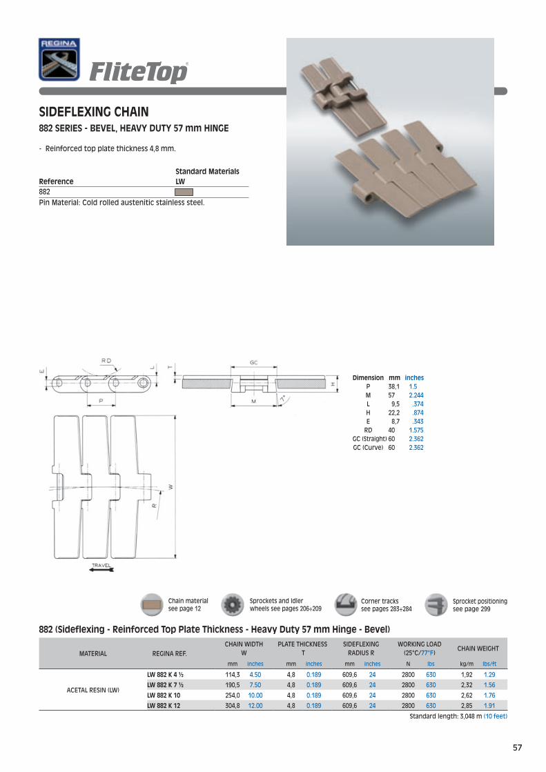
882 Sideflexing Bevel
882TSideflexing TABHeavy Duty hinge
878T200 mm Sideflexing radius
880TASideflexing TAB, for vaccum
HDG 9157 Straight running 57 mm hinge
G 981 Sideflexing Bevel
G 981TSideflexing TAB
G 815 Straight running Single hinge
G 2815 Straight running Double hinge
HDG 9857M Sideflexing Magnetic57 mm hinge
Rubber surface steel chains
Rubber surface plastic chains
G 981M Sideflexing Magnetic

Gripperchains
GV 1874TSteel flights,Short fingers
EV 1874TSteel flights,Long fingers

171
pag.
106
pag.
100
pag.
94
pag.
84
pag.GD 1873T Plastic flights D-shape
GU 1873TPlastic flights U-shape
GW 1873TPlastic flights Short fingers
EW 1873TPlastic flights Long fingers
HG 878TOne-piece 200 mm Sideflexing radius
LBP 821 Straight running Double hinge
LBP 882T SideflexingHeavy Dutyhinge
P600-O Sideflexing, Open surface
P600T-OSideflexing TAB, Open surface
P2600-C Sideflexing, Closed surface
P2600T-CSideflexing TAB, Closed surface
1700 Sideflexing
1702Sideflexing
1701T Sideflexing TAB
Case conveyor chains
Sprockets
Low Back-line Pressure chains
Biplanar chains

Light DutySeries (MetricStandard)
USPMSolid Top 1” pitch 12,7 mm thickness
USPMG ATMActive Transfer Modules Solid Top1” pitch 12,7 mm thickness
793MSideflexing Magnetic 1” pitchSolid Top12,7 mm thickness
793TSideflexing TAB, Solid Top 1” pitch12,7 mm thickness
600 Solid top 1/
2” pitch
8,7 mm thickness
600G ATMActive Transfer modules Solid Top 1/
2” pitch
8,7 mm thickness
1500Flush grid 1” pitch 8,7 mm thickness
1600Solid Top 1” pitch 8,7 mm thickness
Heavy DutySeries (MetricStandard)
USPSolid Top 1” pitch 12,7mm thickness
USPG ATMActive Transfer Modules Solid Top 1” pitch 12,7mm thickness
Heavy DutySeries (AmericanStandard) 793T
Sideflexing TAB, Solid Top 1” pitch12,7 mm thickness

164
pag.
152
pag.
138
pag.
132
pag.
114
pag.
UCC Heavy Duty Series (AmericanStandard)
UCC Solid Top1 1/
2” pitch
12,7 mm thickness
UCCG ATMActive Transfer Modules Solid Top1 1/
2” pitch
12,7 mm thickness
HF USPM Rubber surface 1” pitch12,7 mm thickness
LBP USPMLow Back-line Pressure 1” pitch12,7 mm thickness
3110 Raised Rib2” pitch
3120Raised Rib2” pitch
C24 CAM-CLEAN®
Raised Rib2” pitch
1110Raised Rib, 1” pitch 9,6 mm thickness
1210Flush grid 1” pitch 9,6 mm thickness
1500G ATMActive Transfer Modules Flush Grid 1” pitch 8,7 mm thickness
1600G ATM Active Transfer Modules Solid Top 1” pitch 8,7 mm thickness
1310Solid Top 1” pitch 9,6 mm thickness
782MSideflexing Magnetic Flush Grid 1” pitch8,7 mm thickness
783MSideflexing Magnetic Solid Top 1” pitch 8,7 mm thickness
783TSideflexing TAB, Solid Top 1” pitch8,7 mm thickness
Heavy duty Raised RibSeries
UCC 138Solid TopNo gap between the flights
RR1600Raised Rib 1” pitch 8,7mm thickness
Light DutySeries (AmericanStandard)


298
pag.
288
pag.
280
pag.
238
pag.
218
pag.
Magneticcurves
for FliteTop® and Matveyor®
chains
for FliteTop® chains
Turning discs
for FliteTop® chains
BEVELcurves
TABcurves
for FliteTop® and Matveyor®
chains
Sprockets
Transfercombs
for FliteTop® and Matveyor®
Raised Rib Series
Positioning
for FliteTop®, Matveyor® and Ultop®
chains and belts

12
MATERIALSFliteTop® STEEL CHAINS
Through hardened carbon steel Surface and core hardness of 43 HRC. Excellent strength and wear resistance.Only for dry running application.
Superior grade of cold rolled special ferritic stainless steel Special Cr-Ni alloy offering very good wear and mechanical properties.Particularly suitable for high productivity lines (combiners and inliners).
Cr-Ni austenitic cold rolled stainless steel It guarantees the best corrosion resistance to withstand chemical attack. It offers very good wear resistance, due to work hardening and homogeneous chemical structure.
FliteTop® THERMOPLASTIC CHAINS
DuPont™ Delrin® acetal resin It offers good mechanical strength and wear resistance in combination with low coefficients of friction.
DuPont™ Delrin® special acetal resin It offers improved wear resistance for more demanding applications.Consistently low coefficients of friction.
A superior grade of DuPont™ Delrin® acetal resin reinforced withDuPont™ Kevlar®. Due to the excellent wear resistance, dusting is extremely reduced. In addiction, the coefficient of friction with new glass, PET and can containers is extremely low. Particularly suitable for applications where good lubrication is not possible.
Reinforced polyamideExcellent wear resistance and low dusting. Only for dry running applications. Particularly suitable for glass manufacturing application.
Antistatic acetal resinConductive, it is particularly suitable for all applications where static charge on the chain must be avoided.
Reinforced polypropylene It guarantees the best corrosion resistance to withstand chemical attack.
S
SS
SS-4
Prima
Light Brown
Dark Grey
LW
UP
Dark Grey
DK
Black
Black
AR
AS
Light Blue
P
Flight MaterialRef. Pin Material
Case hardened stainless steel
Cold Rolled ferritic stainless steelGood wear and mechanical resistance.Good corrosion resistance for food & beverage application.
Cold rolled austenitic stainless steel
Cold rolled austenitic stainless steel HD Series: Hardened martensitic stainless steel
Cold rolled austenitic stainless steel
Flight MaterialRef./Color Pin Material
Cold rolled austenitic stainless steelZinc steel
Cold rolled austenitic stainless steelMagnetic Series: magnetic stainless steel
DuPont™ Delrin® acetal resin It offers very good mechanical strength and wear resi-stance in combination with low coefficients of friction.
Cold rolled austenitic stainless steelMagnetic Series: magnetic stainless steel
AcetalWhite
Cold rolled austenitic stainless steelMagnetic Series: magnetic stainless steel
Cold rolled austenitic stainless steel
Cold rolled austenitic stainless steel
Cold rolled austenitic stainless steelPP Series: reinforced light blue polypropylene
DuPont™ Delrin® and DuPont™ Kevlar® are registered trade marks of E.I. DuPont De Nemours and Associates

- 4%
- 20%- 21%
Coefficient of Friction Reduction DK Vs Acetal Resin
Water Water & SoapDry
0,00
10,00
20,00
30,00
40,00
50,00
60,00
70,00
80,00
0 500 1000 1500 2000 2500
0
10
20
30
40
50
60
70
80
90
100
Coefficient of friction comparison with PET bottles
Water Water & SoapDry
- 4%- 20%
- 21%
Sliding distance [Km]
Loss
of
volu
me
pe
r ch
ain
flig
ht
(mm
3 )
Delrin® WITH Kevlar®
ACETAL WITH PTFE
MATERIALSMatveyor®-ULTOP® THERMOPLASTIC CHAINS AND BELTS
Flight MaterialRef./Color Pin Material
DuPont™ Delrin® special acetal resin It offers better wear resistance for more demanding applications.Consistently low coefficients of friction.
A superior grade of DuPont™ Delrin® acetal resin reinforced withDuPont™ Kevlar®. Due to the excellent wear resistance, dusting is extremely reduced. In addiction, the coefficient of friction with new glass, PET and can containers is extremely low. Particularly suitable for applications where good lubrication is not possible.
Light Brown
Dark Grey
LW
UP
Dark Grey
DK
- PBT- 793T Series: austenitic stainless steel- 793M Series: magnetic stainless steel
DuPont™ Delrin® acetal resin It offers very good mechanical strength and wear resi-stance in combination with a low coefficients of friction.
- Polypropylene- PBT- 783T Series: austenitic stainless steel- 782M & 783M Series: magnetic stainless steel
- Polypropylene- PBT- 783T, 793T & UCC Series: austenitic stainless steel- 782M, 783M & 793M Series: magnetic
stainless steel
Reinforced polypropylene It guarantees the best corrosion resistance to withstand chemical attack.
Grey
PP- Polypropylene- PBT
Wear test: New glass bottles in accumulation PET BottlesCoefficient of Friction Reduction DK vs Acetal Resin
DuPont™ Delrin® and DuPont™ Kevlar® are registered trade marks of E.I. DuPont De Nemours and Associates
13

14
WORKING TEMPERATURES AND CHEMICAL RESISTANCE
CHEMICAL AGENT
CARBONSTEEL
(S)
AUSTENITIC STAINLESS
STEEL(SS)
FERRITIC STAINLESS
STEEL(SS-4) - PRIMA
THERMOPLAS-TIC ACETAL (LW) - (AS)(UP) - (DK)
CHEMICALLYRESISTANT
THERMOPLAS-TIC (P)
ABRASIONRESISTANT
THERMOPLAS- TIC (AR)
UHMWPE
ACETIC ACID 5% - * - - * + *ACETONE - * * + * * *ALCOHOL * * * * * * *
AMMONIA CONC. + * * - * * *AMMONIA WATER SOL. + * * * * * *
ANILINE 3% / / / * * / *AQUA REGIA - - - - + / -
BEER + * * * * * *BENZENE * * * * * * +BENZOL * * * * * * +
BRINE ACID - + - + * + *BUTIRYC ACID * * * - * - /
CARBON TETRACHLORIDE + + + * - * +CHLORINE WATER - + + - * - -
CHOCOLATE + * * - + - -CITRIC ACID - * + + * + *
FORMALDEHYDE * * * * * * +FORMIC ACID 10% - - - - * - *
FRUIT JUICE - * + * * * *GASOLINE * * * * + * +
GRAPE HUSK - + - - * - -HYDROCHLORIC ACID 2% - - - - * - *
HYDROCHLORIC ACID 37% - - - - * - *HYDROGEN PEROXIDE - * + - * - *
IODINE - - - - - - -LACTIC ACID - * + * * + *
MILK * * * * * * *MUSTARD * * * - + - -
NITRIC ACID 5% - * * - * - +OIL * * * * - - -
OIL (VEGETABLE &MINERAL) * * * * * * *PARAFIN * * * * * * *
PHOSPHORIC ACID % - * + - * - *SEA WATER - + - + * - *
SOAP & WATER + * * * * * *SODIUM CHLORIDE - + - * * * *
SODIUM HYDROXIDE 25% - * * - * / *SODIUM HYPOCHORITE - + - - * * *
SOFT DRINKS + * * * * * *SPIRITS * * * * * * *
SULPHURIC ACID 40% - - - - * - +TOLUENE / / / + + / -
TURPENTINE * * * / * / -VEGETABLE JUICE + * * * * * *
WATER - * * * * * *WINE * * * * * * *XYLOL / / / / / / /
LEGEND*=SATISFACTORY+=MARGINAL-=UNSATISFACTORY/=UNDETERMINED
FliteTop®, Matveyor® and ULTOP® materials can be used in the range of temperatures stated in the following table:
MATERIALMIN. TEMPERATURE
MAX. TEMPERATURE DRY ENVIRONMENT WET ENVIRONMENT
°C °F °C °F °C °F
STEELCARBON STEEL -40 -40 +180 +356 – –
FERRITIC STAINLESS STEEL & PRIMA -40 -40 +260 +500 +120 +248AUSTENITIC STAINLESS STEEL -40 -40 +425* +797 +120 +248
PLASTIC
ACETAL RESIN (LW, AS, UP, DK) -40 -40 +80 (1) +176 +65 (1) +149CHEMICAL RESISTANT RESIN (P) 0 32 +100 (1) +212 +100 (1) +212
ABRASION RESISTANT (AR)** -40 -40 +120 +248 – –REINFORCED POLYAMIDE -20 -4 +120 +248 +120 +248
* For higher temperatures please contact our technical service. (1) Up to 125°C (257°F) for short exposures** Use in dry environment because water decreases mechanical characteristics and deforms the material.
CHEMICAL RESISTANCE For chemical handling applications it is important to chose the right material for FliteTop®, Matveyor® and ULTOP® series.As a guide TABLE “B” shows the performance characteristics of FliteTop®, Matveyor® and ULTOP® products materials with various chemicals. For chemicals not listed in TABLE “B”, please contact our Technical Services group for advice.
TABLE “B”
TABLE “A”
Data shown in the table was taken from laboratory tests performed on unstrained samples and are merely indicative. Chemical resistance under normal working conditions can depend on various factors, such as stress and temperature, concentration of the chemical agent and duration of its effects.


Steel Chains

18
CARBON STEEL CHAINS
APPLICATIONS (only dry running): - Glass manufacturing - Automotive /mechanical- General purpose conveyors- Heavy loads and abrasive surfaces
STAINLESS STEEL CHAINS
APPLICATIONS: - New glass bottle- Returnable glass bottle- Glass manufacturing- Keg line- Crate conveyors- General purpose conveying
BENEFITS:
- Very good flatness and surface finish- High wear resistance (special alloys)- Reduced transversal and longitudinal gaps (Prima chains)- For stainless steel chains: austenitic stainless steel pins
guarantee high wear resistance for less chain elongation

19
Standard MaterialsReference SS-4 P SSM815
Pin Material: Cold rolled austenitic stainless steel.
STRAIGHT RUNNING CHAINM815 SERIES - FLIGHT GAP 2,8 mmREDUCED BACKFLEXING RADIUS (75 mm)
M815 (Straight Running - Gap 2,8 mm)
MATERIAL REGINA REF.
CHAIN WIDTHW
GAPG
SURFACE FINISH Ra
YIELD LOAD AVERAGE
CHAIN WEIGHT
mm inches mm inches µm N lbs kg/m lbs/ft
FERRITIC STAINLESS STEEL (SS-4) SSM 815-4 K 3 ¼ 82,6 3.25 2,8 0.110 0,3 5800 1,305 2,73 1.83
PRIMA (P) PM 815 K 3 ¼ 82,6 3.25 2,8 0.110 0,3 8500 1,913 2,52 1.69
AUSTENITIC STAINLESS STEEL (SS) SSM 815 K 3 ¼ 82,6 3.25 2,8 0.110 0,4 5600 1,260 2,73 1.83
Standard length: 3,048 m (10 feet)
Sprockets and Idlerwheels see pages 172÷178
Chain materialsee page 12
Sprocket positioningsee page 299
Dimension mm inches P 38,1 1.5 T 3 .118 M 42 1.654 L 6,4 .252 H 13 .512 E 6,35 .25 RD 75 2.953 GC 44 1.732

20
Dimension mm inches P 38,1 1.5 T 3 .118 M 42 1.654 L 6,4 .252 H 13 .512 E 6,35 .25 RD 150 5.906 GC 44 1.732
STRAIGHT RUNNING CHAIN
Standard MaterialsReference S 815
Pin Material: Case hardened steel.
815 (Straight Running - Gap 1,8 mm)
MATERIAL REGINA REF.
CHAIN WIDTHW
GAPG
YIELD LOAD AVERAGE
CHAIN WEIGHT
mm inches mm inches N lbs kg/m lbs/ft
CARBON STEEL (S)
S 815 K 2 ¼ 57,1 2.25 1,8 0.071 12300 2,768 2,05 1.38
S 815 K 2 ½ 63,5 2.50 1,8 0.071 12300 2,768 2,15 1.44
S 815 K 2 5/8 66,7 2.63 1,8 0.071 12300 2,768 2,40 1.61
S 815 K 3 ¼ 82,6 3.25 1,8 0.071 12300 2,768 2,73 1.83
S 815 K 3 ½ 88,9 3.50 1,8 0.071 12300 2,768 3,00 2.02
S 815 K 4 101,6 4.00 1,8 0.071 12300 2,768 3,20 2.15
S 815 K 4 ½ 114,3 4.50 1,8 0.071 12300 2,768 3,48 2.34
S 815 K 6 152,4 6.00 1,8 0.071 12300 2,768 4,38 2.94
S 815 K 7 ½ 190,5 7.50 1,8 0.071 12300 2,768 5,27 3.54
Standard length: 3,048 m (10 feet)
815 SERIES - FLIGHT GAP 1,8 mm
Sprockets and Idlerwheels see pages 172÷178
Chain materialsee page 12
Sprocket positioningsee page 299

21
Dimension mm inches P 38,1 1.5 T 3 .118 M 42 1.654 L 6,4 .252 H 13 .512 E 6,35 .25 RD 150 5.906 GC 44 1.732
STRAIGHT RUNNING CHAIN
Standard MaterialsReference P SS 815
Pin Material: Cold rolled austenitic stainless steel
815 (Straight Running - Gap 1,8 mm)
MATERIAL REGINA REF.
CHAIN WIDTHW
GAPG
SURFACE FINISH Ra
YIELD LOAD AVERAGE
CHAIN WEIGHT
mm inches mm inches µm N lbs kg/m lbs/ft
PRIMA (P)
P 815 K 2 ¼ 57,1 2.25 1,8 0.071 0,3 8500 1,913 1,99 1.34
P 815 K 2 ½ 63,5 2.50 1,8 0.071 0,3 8500 1,913 2,13 1.43
P 815 K 2 5/8 66,7 2.63 1,8 0.071 0,3 8500 1,913 2,19 1.47
P 815 K 2 7/8 73,0 2.87 1,8 0.071 0,3 8500 1,913 2,33 1.57
P 815 K 3 76,2 3.00 1,8 0.071 0,3 8500 1,913 2,40 1.61
P 815 K 3 ¼ 82,6 3.25 1,8 0.071 0,3 8500 1,913 2,54 1.71
P 815 K 3 ½ 88,9 3.50 1,8 0.071 0,3 8500 1,913 2,68 1.80
P 815 K 4 101,6 4.00 1,8 0.071 0,3 8500 1,913 2,97 2.00
P 815 K 4 ½ 114,3 4.50 1,8 0.071 0,3 8500 1,913 3,25 2.18
P 815 K 6 152,4 6.00 1,8 0.071 0,3 8500 1,913 4,09 2.75
P 815 K 7 ½ 190,5 7.50 1,8 0.071 0,3 8500 1,913 4,95 3.33
AUSTENITIC STAINLESS STEEL (SS)
SS 815 K 2 ¼ 57,1 2.25 1,8 0.071 0,4 5600 1,260 2,18 1.46
SS 815 K 2 ½ 63,5 2.50 1,8 0.071 0,4 5600 1,260 2,32 1.56
SS 815 K 2 5/8 66,7 2.63 1,8 0.071 0,4 5600 1,260 2,40 1.61
SS 815 K 2 7/8 73,0 2.87 1,8 0.071 0,4 5600 1,260 2,56 1.72
SS 815 K 3 ¼ 82,6 3.25 1,8 0.071 0,4 5600 1,260 2,73 1.83
SS 815 K 3 ½ 88,9 3.50 1,8 0.071 0,4 5600 1,260 3,00 2.02
SS 815 K 4 101,6 4.00 1,8 0.071 0,4 5600 1,260 3,20 2.15
SS 815 K 4 ½ 114,3 4.50 1,8 0.071 0,4 5600 1,260 3,48 2.34
SS 815 K 6 152,4 6.00 1,8 0.071 0,4 5600 1,260 4,38 2.94
SS 815 K 7 ½ 190,5 7.50 1,8 0.071 0,4 5600 1,260 5,27 3.54
Standard length: 3,048 m (10 feet)
815 SERIES - FLIGHT GAP 1,8 mm
Sprockets and Idlerwheels see pages 172÷178
Chain materialsee page 12
Sprocket positioningsee page 299

22
STRAIGHT RUNNING CHAIN
- Reduced trasversal and longitudinal gap for better product handling.- 83.8 mm wide chains available: for gap reduction on 85 mm transversal pitch conveyors. - XP series: brushed hinges for inliners/inclined combiners
- HD: Increased pin hardness for better resistance to chain elongation
Standard MaterialsReference SS-4 P 915 HD 915
Pin Material: Cold rolled austenitic stainless steel (for 915 series). Hardened martensitic stainless steel (for HD 915 series).
915 (Straight Running - Gap 1,6 mm)
MATERIAL REGINA REF.
CHAIN WIDTHW
GAPG
SURFACE FINISH Ra
YIELD LOAD AVERAGE
CHAIN WEIGHT
mm inches mm inches µm N lbs kg/m lbs/ft
FERRITIC STAINLESS STEEL (SS-4)
SS 915-4 K 3 ¼ 82,6 3.25 1,6 0.063 0,3 5800 1,305 2,52 1.69
SS 915-4 K 83,8 83,8 3.30 1,6 0.063 0,3 5800 1,305 2,55 1.71
SS 915-4 K 4 ½ 114,3 4.50 1,6 0.063 0,3 5800 1,305 3,21 2.16
SS 915-4 K 7 ½ 190,5 7.50 1,6 0.063 0,3 5800 1,305 4,87 3.27
PRIMA (P)
P 915 K 3 ¼ 82,6 3.25 1,6 0.063 0,3 8500 1,913 2,57 1.73
P 915 K 83,8 83,8 3.30 1,6 0.063 0,3 8500 1,913 2,60 1.75
P 915 K 4 ½ 114,3 4.50 1,6 0.063 0,3 8500 1,913 3,28 2.20
P 915 K 7 ½ 190,5 7.50 1,6 0.063 0,3 8500 1,913 4,98 3.35
XP 915 K 3 ¼ 82,6 3.25 1,6 0.063 0,2 8500 1,913 2,57 1.73
XP 915 K 83,8 83,8 3.30 1,6 0.063 0,2 8500 1,913 2,60 1.75
Standard length: 3,048 m (10 feet)
HD 915 (Straight Running - Gap 1,6 mm Increased Pin Hardness)
MATERIAL REGINA REF.
CHAIN WIDTHW
GAPG
SURFACE FINISH Ra
YIELD LOAD AVERAGE
CHAIN WEIGHT
mm inches mm inches µm N lbs kg/m lbs/ft
PRIMA (P)
PHD 915 K 3 ¼ 82,6 3.25 1,6 0.063 0,3 8500 1,913 2,57 1.73
PHD 915 K 83,8 83,8 3.30 1,6 0.063 0,3 8500 1,913 2,60 1.75
PHD 915 K 4 ½ 114,3 4.50 1,6 0.063 0,3 8500 1,913 3,28 2.20
PHD 915 K 7 ½ 190,5 7.50 1,6 0.063 0,3 8500 1,913 4,98 3.35
Standard length: 3,048 m (10 feet)
HD 915 (Straight Running - Gap 1,6 mm Increased Pin Hardness) NE
W
915 SERIES - FLIGHT GAP 1,6 mm
Dimension mm inches P 38,1 1.5 T 3 .118 M 42 1.654 L 6,4 .252 H 13 .512 E 6,35 .25 RD 150 5.906 GC 44 1.732
Sprockets and Idlerwheels see pages 172÷178
Chain materialsee page 12
Sprocket positioningsee page 299
Sprockets and Idlerwheels see pages 172÷178
Chain materialsee page 12
Sprocket positioningsee page 299

23
STRAIGHT RUNNING CHAIN
Standard MaterialsReference S SS-4 P SS2815
Pin Material: Case hardened steel (for carbon steel chains). Cold rolled austenitic stainless steel (for stainless steel chains).
Dimension mm inches P 38,1 1.5 T 3 .118 M 80 3.15 L 6,4 .252 H 13 .512 E 6,35 .25 RD 150 5.906 GC 82,5 3.248
MATERIAL REGINA REF.
CHAIN WIDTHW
GAPG
SURFACE FINISH Ra
YIELD LOAD AVERAGE
CHAIN WEIGHT
mm inches mm inches µm N lbs kg/m lbs/ft
CARBON STEEL (S) S 2815 K 7 ½ 190,5 7.50 1,8 0.071 - 18000 4,050 5,90 3.96
FERRITIC STAINLESS STEEL (SS-4) SS 2815-4 K 7 ½ 190,5 7.50 1,8 0.071 0,3 10300 2,318 5,40 3.62
PRIMA (P) P 2815 K 7 ½ 190,5 7.50 1,8 0.071 0,3 15000 3,375 5,62 3.77
AUSTENITIC STAINLESS STEEL (SS) SS 2815 K 7 ½ 190,5 7.50 1,8 0.071 0,4 10600 2,385 5,40 3.62
Standard length: 3,048 m (10 feet)
2815 (Straight Running - Double Hinge)
2815 SERIES - DOUBLE HINGE
Sprockets and Idlerwheels see pages 179÷183
Chain materialsee page 12
Sprocket positioningsee page 299

24
Dimension mm inches P 38,1 1.5 T 3 .118 M 57 2.244 L 6,4 .252 H 13 .512 E 6,35 .25 RD 150 5.906 GC 60 2.362
STRAIGHT RUNNING CHAIN
Standard MaterialsReference P HD 9157
Pin Material: Hardened martensitic stainless steel
MATERIAL REGINA REF.
CHAIN WIDTHW
GAPG
SURFACE FINISH Ra
YIELD LOAD AVERAGE
CHAIN WEIGHT
mm inches mm inches µm N lbs kg/m lbs/ft
PRIMA (P) PHD 9157 K 7 ½ 190,5 7.50 1,6 0.063 0,3 10500 2,363 5,28 3.55
Standard length: 3,048 m (10 feet)
HD 9157 (Straight Running - Heavy Duty - 57 mm Hinge - Increased Pin Hardness )
- HD: Increased pin hardness for better resistance to chain elongation.
HD 9157 NEW
9157 SERIES - HEAVY DUTY 57 mm HINGE.
Sprockets and Idlerwheels see pages 184÷185
Chain materialsee page 12
Sprocket positioningsee page 299

25
STRAIGHT RUNNING CHAIN
MATERIAL REGINA REF.
CHAIN WIDTHW
GAPG
SURFACE FINISH Ra
YIELD LOAD AVERAGE
CHAIN WEIGHT
mm inches mm inches µm N lbs kg/m lbs/ft
PRIMA (P)P 803 K 1 ¼ 31,8 1.25 2,8 0.110 0,3 4100 923 1,07 0.72
P 803 K 1 ¾ 44,5 1.75 2,8 0.110 0,3 4100 923 1,34 0.90
Standard length: 3,048 m (10 feet)
803 (Straight Running - Mini Hinge)
Dimension mm inches P 38,1 1.5 T 3 .118 M 22 .866 L 6,4 .252 H 13 .512 E 6,35 .25 RD 75 2.953 GC 24 .945
Standard MaterialsReference P 803
Pin Material: Cold rolled austenitic stainless steel
Sprockets see pages 186÷187
Chain materialsee page 12
Sprocket positioningsee page 299
803 SERIES - MINI HINGE

26
Dimension mm inches P 25,4 1 T 3 .118 M 42 1.654 L 6,4 .252 H 13 .512 E 6,35 .25 RD 100 3.937 GC 44 1.732
STRAIGHT RUNNING CHAIN
- Particularly suitable for bottle washer infeed applications
Standard MaterialsReference SS 515
Pin Material: Cold rolled austenitic stainless steel.
515 (Straight Running - Short Pitch)
MATERIAL REGINA REF.
CHAIN WIDTHW
GAPG
SURFACE FINISH Ra
YIELD LOAD AVERAGE
CHAIN WEIGHT
mm inches mm inches µm N lbs kg/m lbs/ft
AUSTENITIC STAINLESS STEEL (SS)
SS 515 K 50 50,0 1.97 1,6 0.063 0,4 5600 1,260 2,20 1.48
SS 515 K 55 55,0 2.17 1,6 0.063 0,4 5600 1,260 2,30 1.55
SS 515 K 60 60,0 2.36 1,6 0.063 0,4 5600 1,260 2,40 1.61
SS 515 K 2 ½ 63,5 2.50 1,6 0.063 0,4 5600 1,260 2,50 1.68
SS 515 K 72 72,0 2.83 1,6 0.063 0,4 5600 1,260 2,70 1.81
SS 515 K 3 ¼ 82,6 3.25 1,6 0.063 0,4 5600 1,260 2,90 1.95
SS 515 K 3 ½ 88,9 3.50 1,6 0.063 0,4 5600 1,260 3,00 2.02
SS 515 K 100 100,0 3.94 1,6 0.063 0,4 5600 1,260 3,30 2.22
Standard length: 3,048 m (10 feet)
515 SERIES - 1’’ PITCH
Sprockets see pages 188÷189
Chain materialsee page 12
Sprocket positioningsee page 299

27
Dimension mm inches P 38,1 1.5 T 3 .118 M 43 1.693 N 38,3 1.508 L 6,4 .252 H 14,5 .571 E 6,35 .25 F 13 .512 RD 75 2.953 GC (Straight) 44,5 1.752 GC (Curve) 41,5 1.634
SIDEFLEXING CHAIN
Standard MaterialsReference S SS 881
Pin Material: Case hardened steel (for carbon steel chains). Cold rolled austenitic stainless steel (for stainless steel chains).
881 (Sideflexing - Bevel)
MATERIAL REGINA REF.
CHAIN WIDTHW
SURFACE FINISH Ra
SIDEFLEXING RADIUS R
YIELD LOAD AVERAGE
CHAIN WEIGHT
mm inches µm mm inches N lbs kg/m lbs/ft
CARBON STEEL (S)
S 881 K 3 ¼ 82,6 3.25 - 457,2 18 11600 2,610 3,00 2.02
S 881 K 4 ½ 114,3 4.50 - 609,6 24 11600 2,610 3,70 2.49
S 881 K 7 ½ 190,5 7.50 - 609,6 24 11600 2,610 5,50 3.70
AUSTENITIC STAINLESS STEEL (SS)
SS 881 K 3 ¼ 82,6 3.25 0,4 457,2 18 5600 1,260 3,00 2.02
SS 881 K 4 ½ 114,3 4.50 0,4 609,6 24 5600 1,260 3,70 2.49
SS 881 K 7 ½ 190,5 7.50 0,4 609,6 24 5600 1,260 5,50 3.70
Standard length: 3,048 m (10 feet)
881 SERIES - BEVEL
Corner trackssee page 283
Sprockets and Idlerwheels see pages 190÷195
Chain materialsee page 12
Sprocket positioningsee page 299

28
SIDEFLEXING CHAIN
Standard MaterialsReference S SS 881T
Pin Material: Case hardened steel (for carbon steel chains). Cold rolled austenitic stainless steel (for stainless steel chains).
881T (Sideflexing - Tab)
MATERIAL REGINA REF.
CHAIN WIDTHW
SURFACE FINISH Ra
SIDEFLEXING RADIUS R
YIELD LOAD AVERAGE
CHAIN WEIGHT
mm inches µm mm inches N lbs kg/m lbs/ft
CARBON STEEL (S)
S 881T K 3 ¼ 82,6 3.25 - 457,2 18 11600 2,610 3,20 2.15
S 881T K 4 ½ 114,3 4.50 - 609,6 24 11600 2,610 3,90 2.62
S 881T K 7 ½ 190,5 7.50 - 609,6 24 11600 2,610 5,70 3.83
AUSTENITIC STAINLESS STEEL (SS)
SS 881T K 3 ¼ 82,6 3.25 0,4 457,2 18 5600 1,260 3,20 2.15
SS 881T K 4 ½ 114,3 4.50 0,4 609,6 24 5600 1,260 3,90 2.62
SS 881T K 7 ½ 190,5 7.50 0,4 609,6 24 5600 1,260 5,70 3.83
Standard length: 3.048 m (10 feet)
881T SERIES - TAB
Corner trackssee page 280
Sprockets and Idlerwheels see pages 190÷195
Chain materialsee page 12
Sprocket positioningsee page 299
Dimension mm inches P 38,1 1.5 T 3 .118 M 43 1.693 N 38,3 1.508 C 56 2.205 L 6,4 .252 H 19,3 .76 E 6,35 .25 B 12,8 .504 F 13 .512 RD 75 2.953 GC (Straight) 46 1.811 GC (Curve) 44,5 1.752

29
SIDEFLEXING CHAIN
Standard MaterialsReference P 981
Pin Material: Cold rolled austenitic stainless steel.
981 (Sideflexing - Bevel)
MATERIAL REGINA REF.
CHAIN WIDTHW
SURFACE FINISH Ra
SIDEFLEXING RADIUS R
YIELD LOAD AVERAGE
CHAIN WEIGHT
mm inches µm mm inches N lbs kg/m lbs/ft
PRIMA (P)
P 981 K 3 ¼ 82,6 3.25 0,3 457,2 18 8000 1,800 2,72 1.83
P 981 K 83,8 83,8 3.30 0,3 457,2 18 8000 1,800 2,75 1.85
P 981 K 4 ½ 114,3 4.50 0,3 609,6 24 8000 1,800 3,35 2.25
P 981 K 7 ½ 190,5 7.50 0,3 609,6 24 8000 1,800 4,76 3.20
Standard length: 3,048 m (10 feet)
- 83.8 mm wide chains available: for gap reduction on 85 mm transversal pitch conveyors.
Corner trackssee page 283
Sprockets and Idlerwheels see pages 190÷195
Chain materialsee page 12
Sprocket positioningsee page 299
981 SERIES - BEVEL, REDUCED FLIGHT GAP
Dimension mm inches P 38,1 1.5 T 3 .118 M 43 1.693 N 38,3 1.508 L 6,4 .252 H 14,5 .571 E 6,35 .25 F 13 .512 RD 75 2.953 GC (Straight) 44,5 1.752 GC (Curve) 41,5 1.634

30
Dimension mm inches P 38,1 1.5 T 3 .118 M 43 1.693 N 38,3 1.508 C 56 2.205 L 6,4 .252 H 19,3 .76 E 6,35 .25 B 12,8 .504 F 13 .512 RD 75 2.953 GC (Straight) 46 1.811 GC (Curve) 44,5 1.752
SIDEFLEXING CHAIN
Standard MaterialsReference P 981T
Pin Material: Cold rolled austenitic stainless steel.
981T (Sideflexing - Tab)
MATERIAL REGINA REF.
CHAIN WIDTHW
SURFACE FINISH Ra
SIDEFLEXING RADIUS R
YIELD LOAD AVERAGE
CHAIN WEIGHT
mm inches µm mm inches N lbs kg/m lbs/ft
PRIMA (P)
P 981T K 3 ¼ 82,6 3.25 0,3 457,2 18 8000 1,800 2,95 1.98
P 981T K 83,8 83,8 3.30 0,3 457,2 18 8000 1,800 2,96 1.98
P 981T K 4 ½ 114,3 4.50 0,3 609,6 24 8000 1,800 3,58 2.41
P 981T K 7 ½ 190,5 7.50 0,3 609,6 24 8000 1,800 4,99 3.35
Standard length: 3,048 m (10 feet)
- 83.8 mm wide chains available: for gap reduction on 85 mm transversal pitch conveyors.
NEWCorner tracks
see page 280Sprockets and Idlerwheels see pages 190÷195
Chain materialsee page 12
Sprocket positioningsee page 299
981T SERIES - TAB, REDUCED FLIGHT GAP

31
Standard MaterialsReference SS-4 P 981M
HD 981M
Pin Material: Cold rolled austenitic stainless steel (for 981M series). Hardened martensitic stainless steel (for HD 981M series).
SIDEFLEXING CHAIN
Dimension mm inches P 38,1 1.5 T 3 .118 M 42 1.654 L 6,4 .252 H 13 .512 E 6,35 .25 RD 75 2.953 GC (Straight) 44 1.732 GC (Curve) 44 1.732
981M (Sideflexing - Magnetic)
MATERIAL REGINA REF.
CHAIN WIDTHW
SURFACE FINISH Ra
SIDEFLEXING RADIUS R
YIELD LOAD AVERAGE
CHAIN WEIGHT
mm inches µm mm inches N lbs kg/m lbs/ft
FERRITIC STAINLESS STEEL (SS-4)SS 981M-4 K 3 ¼ 82,6 3.25 0,3 500 19.69 5400 1,215 2,40 1.61
SS 981M-4 K 83,8 83,8 3.30 0,3 500 19.69 5400 1,215 2,42 1.63
PRIMA (P)
P 981M K 3 ¼ 82,6 3.25 0,3 500 19.69 8500 1,913 2,46 1.65
P 981M K 83,8 83,8 3.30 0,3 500 19.69 8500 1,913 2,48 1.67
P 981M K 4 ½ 114,3 4.50 0,3 500 19.69 8500 1,913 3,08 2.07
P 981M K 7 ½ 190,5 7.50 0,3 500 19.69 8500 1,913 4,47 3.00
Standard length: 3,048 m (10 feet)
HD 981M (Sideflexing - Magnetic - Increased Pin Hardness)
MATERIAL REGINA REF.
CHAIN WIDTHW
SURFACE FINISH Ra
SIDEFLEXING RADIUS R
YIELD LOAD AVERAGE
CHAIN WEIGHT
mm inches µm mm inches N lbs kg/m lbs/ft
PRIMA (P)
PHD 981M K 3 ¼ 82,6 3.25 0,3 500 19.69 8500 1,913 2,46 1.65
PHD 981M K 83,8 83,8 3.30 0,3 500 19.69 8500 1,913 2,48 1.67
PHD 981M K 4 ½ 114,3 4.50 0,3 500 19.69 8500 1,913 3,08 2.07
PHD 981M K 7 ½ 190,5 7.50 0,3 500 19.69 8500 1,913 4,47 3.00
Standard length: 3,048 m (10 feet)
- Brushed side hinge to reduce wear of magnetic curves.- 83.8 mm wide chains available: for gap reduction on 85 mm transversal pitch conveyors.
- HD: Increased pin hardness for better resistance to chain elongation.
HD 981M (Sideflexing - NEW
Corner trackssee page 241
Sprockets and Idlerwheels see pages 172÷178
Chain materialsee page 12
Sprocket positioningsee page 299
981M SERIES - MAGNETIC, REDUCED FLIGHT GAP
Corner trackssee page 241
Sprockets and Idlerwheels see pages 172÷178
Chain materialsee page 12
Sprocket positioningsee page 299

32
HD 9857M (Sideflexing - Magnetic - Heavy Duty 57 mm Hinge - Increased Pin Hardness)
MATERIAL REGINA REF.
CHAIN WIDTHW
SURFACE FINISH Ra
SIDEFLEXING RADIUS R
YIELD LOAD AVERAGE
CHAIN WEIGHT
mm inches µm mm inches N lbs kg/m lbs/ft
PRIMA (P) PHD 9857M K 7 ½ 190,5 7.50 0,3 750 29.53 10500 2,363 4,97 3.34
Standard length: 3,048 m (10 feet)
Dimension mm inches P 38,1 1.5 T 3 .118 M 57 2.244 L 6,4 .252 H 13 .512 E 6,35 .25 RD 75 2.953 GC (Straight) 60 2.362 GC (Curve) 60 2.362
SIDEFLEXING CHAIN
Standard MaterialsReference P HD 9857M
Pin Material: Hardened martensitic stainless steel.
- Brushed side hinge to reduce wear of magnetic curves.- HD: Increased pin hardness for better resistance to chain elongation.
HD 9857M (Sideflexing - Magnetic - Heavy Duty NEW
Corner trackssee page 241
Sprockets and Idlerwheels see pages 184÷185
Chain materialsee page 12
Sprocket positioningsee page 299
9857M SERIES - MAGNETIC, HEAVY DUTY 57 mm HINGE

33
Standard MaterialsReference SS 982T
Pin Material: Cold rolled austenitic stainless steel.
SIDEFLEXING CHAIN
Dimension mm inches P 38,1 1.5 T 3 .118 M 43 1.693 N 38,3 1.508 C 56 2.205 L 6,4 .252 H 19,3 .76 E 6,35 .25 B 12,8 .504 F 13 .512 RD 75 2.953 GC (Straight) 46 1.811 GC (Curve) 44,5 1.752
982T (Sideflexing - Tab - Reduced Sideflexing Radius)
MATERIAL REGINA REF.
CHAIN WIDTHW
SURFACE FINISH Ra
SIDEFLEXING RADIUS R
YIELD LOAD AVERAGE
CHAIN WEIGHT
mm inches µm mm inches N lbs kg/m lbs/ft
AUSTENITIC STAINLESS STEEL (SS) SS 982T K 3 ¼ 82,6 3.25 0,4 200 7.874 5000 1,125 3,00 2.02
Standard length: 3,048 m (10 feet)
- Suitable for use with turning discs (Ref. CMA 09 878)
Sprockets and Idlerwheels see pages 190÷195
Chain materialsee page 12
Sprocket positioningsee page 299
982T SERIES - TAB, REDUCED SIDEFLEXING RADIUS (200 mm)


Rubber SurfaceStainless Steel Chains

36
STAINLESS STEEL CHAINS WITH RUBBER SURFACE
APPLICATIONS: - Conveying of plastic crates on inclined conveyors (Maximum ramp
angle of 25°; for higher angles, please contact Regina Application Engineering).
BENEFITS:
- The nitrile rubber pad offers the best wear resistance and long life. Vulcanization process offers optimum adhesion of the rubber pads to the flight.
RUBBERMATERIAL
COLOURAVERAGE
HARDNESS
MINTEMPERATURE
°C °F
MAX TEMPERATUREWITHOUT LUBRICATION DAMP ENVIRONMENT NON SUITABLE WITH RESISTANT TO
°C °F °C °F
NITRILE BLACK 55 ShA -10 +14 +110 +230 +80 +176 STRONG ACID AND BASES OILS
Rubber standard material

37
Dimension mm inches P 38,1 1.5 T 3 .118 S 2 .079 M 42 1.654 L 6,4 .252 H 13 .512 E 6,35 .25 Z 76 2.992 RD 150 5.906 GC 44 1.732
STRAIGHT RUNNING CHAINWITH RUBBER SURFACE
Standard MaterialsReference P G 815
Pad Material: Nitrile rubber (see page 36).Pin Material: Cold rolled austenitic stainless steel
MATERIAL REGINA REF.
CHAIN WIDTHW
GAPG
YIELD LOAD AVERAGE
CHAIN WEIGHT
mm inches mm inches N lbs kg/m lbs/ft
PRIMA (P)
PG 815 K 3 ¼ 82,6 3.25 1,8 0.071 8500 1,913 2,66 1.79
PG 815 K 4 ½ 114,3 4.50 1,8 0.071 8500 1,913 3,37 2.26
PG 815 K 7 ½ 190,5 7.50 1,8 0.071 8500 1,913 5,24 3.52
Standard length: 3,048 m (10 feet)
G 815 (Straight Running - Rubber Surface)
Dimension mm inches P 38,1 1.5 T 3 .118 S 2,8 .11 M 42 1.654 L 6,4 .252 H 13 .512 E 6,35 .25 Z 146 5.748 RD 150 5.906 GC 44 1.732
Sprockets and Idlerwheels see pages 172÷178
Chain materialsee page 12
Sprocket positioningsee page 299
G 815 SERIES - SINGLE HINGE
K 3¼ - K 4½
K 7½

38
STRAIGHT RUNNING CHAIN WITH RUBBER SURFACE
Standard MaterialsReference P G 2815
Pad Material: Nitrile rubber (see page 36).Pin Material: Cold rolled austenitic stainless steel.
MATERIAL REGINA REF.
CHAIN WIDTHW
GAPG
YIELD LOAD AVERAGE
CHAIN WEIGHT
mm inches mm inches N lbs kg/m lbs/ft
PRIMA (P) PG 2815 K 7 ½ 190,5 7.50 1,8 0.071 15000 3,375 5,94 3.99
Standard length: 3,048 m (10 feet)
G 2815 (Straight Running - Double Hinge - Rubber Surface)
Dimension mm inches P 38,1 1.5 T 3 .118 S 2,8 .11 M 80 3.15 L 6,4 .252 H 13 .512 E 6,35 .25 Z 140 5.512 RD 150 5.906 GC 82,5 3.248
NEW
G 2815 SERIES - DOUBLE HINGE
Sprockets and Idlerwheels see pages 179÷183
Chain materialsee page 12
Sprocket positioningsee page 299

39
Dimension mm inches P 38,1 1.5 T 3 .118 S 3 .118 M 57 2.244 L 6,4 .252 H 13 .512 E 6,35 .25 Z 140 5.512 RD 150 5.906 GC 60 2.362
STRAIGHT RUNNING CHAINWITH RUBBER SURFACE
Standard MaterialsReference P HDG 9157
Pad Material: Nitrile rubber (see page 36).Pin Material: Hardened martensitic stainless steel
MATERIAL REGINA REF.
CHAIN WIDTHW
GAPG
YIELD LOAD AVERAGE
CHAIN WEIGHT
mm inches mm inches N lbs kg/m lbs/ft
PRIMA (P) PHDG 9157 K 7 ½ 190,5 7.50 1,6 0.063 10500 2,363 5,60 3.76
Standard length: 3,048 m (10 feet)
HDG 9157 (Straight Running - Heavy Duty 57 mm Hinge - Increased Pin Hardness - Rubber Surface)HDG 9157 NEW
- HD: Increased pin hardness for better resistance to chain elongation.
Sprockets and Idlerwheels see pages 184÷185
Chain materialsee page 12
Sprocket positioningsee page 299
G 9157 SERIES - HEAVY DUTY 57 mm HINGE

40
SIDEFLEXING CHAIN WITH RUBBER SURFACE
Standard MaterialsReference P G 981
Pad Material: Nitrile rubber (see page 36).Pin Material: Cold rolled austenitic stainless steel.
MATERIAL REGINA REF.
CHAIN WIDTHW
SIDEFLEXING RADIUSR
YIELD LOAD AVERAGE
CHAIN WEIGHT
mm inches mm inches N lbs kg/m lbs/ft
PRIMA (P) PG 981 K 3 ¼ 82,6 3.25 457,2 18 8000 1,800 2,90 1.95
Standard length: 3,048 m (10 feet)
G 981 (Sideflexing - Bevel - Rubber Surface)
Corner trackssee page 283
Sprockets and Idlerwheels see pages 190÷195
Chain materialsee page 12
Sprocket positioningsee page 299
G 981 SERIES - BEVEL, REDUCED FLIGHT GAP
Dimension mm inches P 38,1 1.5 T 3 .118 S 2 .079 M 43 1.693 N 38,3 1.508 L 6,4 .252 H 14,5 .571 E 6,35 .25 F 13 .512 Z 76 2.992 RD 75 2.953GC (Straight) 44,5 1.752 GC (Curve) 44,5 1.634

41
SIDEFLEXING CHAIN WITH RUBBER SURFACE
Standard MaterialsReference P G 981T
Pad Material: Nitrile rubber (see page 36).Pin Material: Cold rolled austenitic stainless steel
MATERIAL REGINA REF.
CHAIN WIDTHW
SIDEFLEXING RADIUSR
YIELD LOAD AVERAGE
CHAIN WEIGHT
mm inches mm inches N lbs kg/m lbs/ft
PRIMA (P)PG 981T K 3 ¼ 82,6 3.25 457,2 18 8000 1,800 3,07 2.06
PG 981T K 7 ½ 190,5 7.50 609,6 24 8000 1,800 5,30 3.56
Standard length: 3,048 m (10 feet)
G 981T (Sideflexing - Tab - Rubber Surface)
G 981T SERIES - TAB, REDUCED FLIGHT GAP
Corner trackssee page 280
Sprockets and Idlerwheels see pages 190÷195
Chain materialsee page 12
Sprocket positioningsee page 299
K 3¼
K 7½
Dimension mm inches P 38,1 1.5 T 3 .118 S 2 .079 M 43 1.693 N 38,3 1.508 C 56 2.205 L 6,4 .252 H 19,3 .760 E 6,35 .25 B 12,8 .504 F 13 .512 Z 76 2.992 RD 75 2.953GC (Straight) 46 1.811 GC (Curve) 44,5 1.752
Dimension mm inches P 38,1 1.5 T 3 .118 S 2,8 .11 M 43 1.693 N 38,3 1.508 C 56 2.205 L 6,4 .252 H 19,3 .76 E 6,35 .25 B 12,8 .504 F 13 .512 Z 146 5.748 RD 75 2.953GC (Straight) 46 1.811 GC (Curve) 44,5 1.752

42
SIDEFLEXING CHAIN WITH RUBBER SURFACE
Standard MaterialsReference P G 981M
Pad Material: Nitrile rubber (see page 36).Pin Material: Cold rolled austenitic stainless steel.
MATERIAL REGINA REF.
CHAIN WIDTHW
SIDEFLEXING RADIUSR
YIELD LOAD AVERAGE
CHAIN WEIGHT
mm inches mm inches N lbs kg/m lbs/ft
PRIMA (P) PG 981M K 7 ½ 190,5 7.50 500 19.685 8500 1,913 4,77 3.21
Standard length: 3,048 m (10 feet)
G 981M (Sideflexing - Magnetic - Rubber Surface) NEW
G 981M SERIES - MAGNETIC, REDUCED FLIGHT GAP
Corner trackssee page 241
Sprockets and Idlerwheels see pages 172÷178
Chain materialsee page 12
Sprocket positioningsee page 299
Dimension mm inches P 38,1 1.5 T 3 .118 S 2,8 .11 M 42 1.654 L 6,4 .252 H 13 .512 E 6,35 .25 Z 146 5.748 RD 75 2.953GC (Straight) 44 1.732 GC (Curve) 44 1.732

43
Dimension mm inches P 38,1 1.5 T 3 .118 S 3 .118 M 57 2.244 L 6,4 .252 H 13 .512 E 6,35 .25 Z 140 5.512 RD 75 2.953GC (Straight) 60 2.362 GC (Curve) 60 2.362
SIDEFLEXING CHAIN WITH RUBBER SURFACE
Standard MaterialsReference P HDG 9857M
Pad Material: Nitrile rubber (see page 36).Pin Material: Hardened martensitic stainless steel
MATERIAL REGINA REF.
CHAIN WIDTHW
SIDEFLEXING RADIUSR
YIELD LOAD AVERAGE
CHAIN WEIGHT
mm inches mm inches N lbs kg/m lbs/ft
PRIMA (P) PHDG 9857M K 7 ½ 190,5 7.50 750 29.528 10500 2,363 5,26 3.53
Standard length: 3,048 m (10 feet)
HDG 9857M (Sideflexing - Magnetic - Heavy Duty 57 mm Hinge - Increased Pin Hardness - Rubber Surface)
- Brushed side hinge to reduce wear of magnetic curves.- HD: Increased pin hardness for better resistance to chain elongation.
HDG 9857M NEW
G 9857M SERIES - MAGNETIC, HEAVY DUTY 57 mm HINGE
Corner trackssee page 241
Sprockets and Idlerwheels see pages 184÷185
Chain materialsee page 12
Sprocket positioningsee page 299


Thermoplastic Chains

46
THERMOPLASTIC CHAINS
APPLICATIONS: - Pet bottle- Pet petaloid bottle- Aluminum and steel can- Cartons- Non Returnable glass- Glass mfg- Packaged products (cartons, shrink packs)- Paper and cardboard- General purpose conveyors
BENEFITS:
- DuPont™ Delrin® acetal resins give the maximum mechanical strength in the class and high wear resistance
- Accuracy of molding process guarantees optimum flatness- Austenitic pin with high corrosion and wear resistance- Availability of a complete range of straight running and sideflexing
83.8 mm wide chains, for gap reduction on 85mm pitch conveyors
DuPont™ Delrin® and DuPont™ Kevlar® are registered trade marks of E.I. DuPont De Nemours and Associates

47
DK (DuPont™ Delrin® with DuPont™ Kevlar®) CHAINS
APPLICATIONS: - Glass manufacturing PET, aluminium can, glass bottle lines where
good lubrication is not possible
BENEFITS:
- DK material has excellent wear resistance. Consequently, dusting on conveyors is very limited and chain life is longer
Lower coefficient of friction = lower pressure on containers in the accumulation sections of conveyor
- High productivity of combiners
AR (ABRASION RESISTANT) CHAINS
APPLICATIONS (ONLY DRY RUNNING):
- Glass manufacturing- Automotive/mechanical- General purpose conveyors
BENEFITS:
- Dusting on conveyors is very limited- Excellent wear resistance
0,00
10,00
20,00
30,00
40,00
50,00
60,00
70,00
80,00
0 500 1000 1500 2000 2500
0
10
20
30
40
50
60
70
80
90
100
Coefficient of friction comparison with PET bottles
Water Water & SoapDry
- 4%- 20%
- 21%
Sliding distance [Km]
Loss
of
volu
me
pe
r ch
ain
flig
ht
(mm
3 )
Delrin® WITH Kevlar®
ACETAL WITH PTFE
Wear test: New glass bottles in accumulation
DuPont™ Delrin® and DuPont™ Kevlar® are registered trade marks of E.I. DuPont De Nemours and Associates

48
Dimension mm inches P 38,1 1.5 M 41,6 1.638 L 7,2 .283 H 14,3 .563 E 6,35 .25 RD 40 1.575 GC 44 1.732
STRAIGHT RUNNING CHAIN
- 83.8 mm wide chains available: for gap reduction on 85 mm transversal pitch conveyors.
Standard MaterialsReference LW UP DK 820
Pin Material: Cold rolled austenitic stainless steel.
MATERIAL REGINA REF.
CHAIN WIDTHW
PLATE THICKNESS T
WORKING LOAD(25°C/77°F)
CHAIN WEIGHT
mm inches mm inches N lbs kg/m lbs/ft
ACETAL RESIN (LW)
LW 820 K 3 ¼ 82,6 3.25 4,0 0.157 1600 360 0,87 0.58
LW 820 K 83,8 83,8 3.30 4,0 0.157 1600 360 0,88 0.59
LW 820 K 87 87,0 3.43 4,0 0.157 1600 360 0,93 0.62
LW 820 K 4 101,6 4.00 4,0 0.157 1600 360 0,95 0.64
LW 820 K 4 ½ 114,3 4.50 4,0 0.157 1600 360 1,03 0.69
LW 820 K 6 152,4 6.00 4,0 0.157 1600 360 1,25 0.84
LW 820 K 7 ½ 190,5 7.50 4,0 0.157 1600 360 1,47 0.99
ULTRA PERFORMANCEACETAL RESIN (UP)
UP 820 K 3 ¼ 82,6 3.25 4,0 0.157 1600 360 0,87 0.58
UP 820 K 83,8 83,8 3.30 4,0 0.157 1600 360 0,88 0.59
UP 820 K 4 101,6 4.00 4,0 0.157 1600 360 0,95 0.64
UP 820 K 4 ½ 114,3 4.50 4,0 0.157 1600 360 1,03 0.69
UP 820 K 6 152,4 6.00 4,0 0.157 1600 360 1,25 0.84
UP 820 K 7 ½ 190,5 7.50 4,0 0.157 1600 360 1,47 0.99
REGINA DK
DK 820 K 3 ¼ 82,6 3.25 4,0 0.157 1600 360 0,87 0.58
DK 820 K 83,8 83,8 3.30 4,0 0.157 1600 360 0,88 0.59
DK 820 K 4 ½ 114,3 4.50 4,0 0.157 1600 360 1,03 0.69
Standard length: 3,048 m (10 feet)
820 (Straight Running)
820 SERIES
Sprockets and Idlerwheels see pages 196÷199
Chain materialsee page 12
Sprocket positioningsee page 299

49
Dimension mm inches P 38,1 1.5 M 41,6 1.638 L 7,2 .283 H 14,3 .563 E 6,35 .25 RD 40 1.575 GC 44 1.732
STRAIGHT RUNNING CHAIN
Standard MaterialsReference *P *AR AS 820
Pin Material: Cold rolled austenitic stainless steel. Chemical resistant light blue resin (for PP series).
MATERIAL REGINA REF.
CHAIN WIDTHW
PLATE THICKNESS T
WORKING LOAD(25°C/77°F)
CHAIN WEIGHT
mm inches mm inches N lbs kg/m lbs/ft
ABRASION RESISTANTRESIN* (AR)
AR 820 K 3 ¼ 82,6 3.25 4,0 0.157 1300 293 0,84 0.56
AR 820 K 4 ½ 114,3 4.50 4,0 0.157 1300 293 1,02 0.69
ANTISTATIC RESIN (AS)
AS 820 K 3 ¼ 82,6 3.25 4,0 0.157 1200 270 0,87 0.58
AS 820 K 4 ½ 114,3 4.50 4,0 0.157 1200 270 1,02 0.69
AS 820 K 7 ½ 190,5 7.50 4,0 0.157 1200 270 1,47 0.99
CHEMICAL RESISTANTRESIN* (P)
P 820 K 3 ¼ 82,6 3.25 4,0 0.157 800 180 1,02 0.69
P 820 K 4 101,6 4.00 4,0 0.157 800 180 1,15 0.77
P 820 K 4 ½ 114,3 4.50 4,0 0.157 800 180 1,21 0.81
P 820 K 6 152,4 6.00 4,0 0.157 800 180 1,41 0.95
P 820 K 7 ½ 190,5 7.50 4,0 0.157 800 180 1,69 1.14
PP 820 K 3 ¼ 82,6 3.25 4,0 0.157 800 180 0,78 0.52
PP 820 K 4 101,6 4.00 4,0 0.157 800 180 0,91 0.61
PP 820 K 4 ½ 114,3 4.50 4,0 0.157 800 180 0,98 0.66
PP 820 K 6 152,4 6.00 4,0 0.157 800 180 1,17 0.79
PP 820 K 7 ½ 190,5 7.50 4,0 0.157 800 180 1,46 0.98
* Due to different shrinkage of materials, actual width is larger than the standard. Standard length: 3,048 m (10 feet)
820 (Straight Running)
820 SERIES
Sprockets and Idlerwheels see pages 196÷199
Chain materialsee page 12
Sprocket positioning see page 299

50
Dimension mm inches P 38,1 1.5 M 41,6 1.638 L 7,2 .283 H 14,3 .563 E 6,35 .25 RD 40 1.575 GC 44 1.732
Standard MaterialsReference LW UP DK831
Pin Material: Cold rolled austenitic stainless steel.
MATERIAL REGINA REF.
CHAIN WIDTHW
PLATE THICKNESS T
WORKING LOAD(25°C/77°F)
CHAIN WEIGHT
mm inches mm inches N lbs kg/m lbs/ft
ACETAL RESIN (LW)
LW 831 K 3 ¼ 82,6 3.25 4,8 0.189 1600 360 0,90 0.60
LW 831 K 83,8 83,8 3.30 4,8 0.189 1600 360 0,91 0.61
LW 831 K 4 ½ 114,3 4.50 4,8 0.189 1600 360 1,09 0.73
LW 831 K 7 ½ 190,5 7.50 4,8 0.189 1600 360 1,51 1.01
ULTRA PERFORMANCEACETAL RESIN (UP)
UP 831 K 3 ¼ 82,6 3.25 4,8 0.189 1600 360 0,90 0.60
UP 831 K 83,8 83,8 3.30 4,8 0.189 1600 360 0,91 0.61
UP 831 K 4 ½ 114,3 4.50 4,8 0.189 1600 360 1,09 0.73
UP 831 K 7 ½ 190,5 7.50 4,8 0.189 1600 360 1,51 1.01
REGINA DK
DK 831 K 3 ¼ 82,6 3.25 4,8 0.189 1600 360 0,90 0.60
DK 831 K 83,8 83,8 3.30 4,8 0.189 1600 360 0,91 0.61
DK 831 K 4 ½ 114,3 4.50 4,8 0.189 1600 360 1,09 0.73
Standard length: 3,048 m (10 feet)
831 (Straight Running - Reinforced Top Plate Thickness)
STRAIGHT RUNNING CHAIN
- Reinforced top plate thickness 4,8 mm.- 83.8mm wide chains available: for gap reduction on 85 mm transversal pitch conveyors.
831 SERIES - REINFORCED TOP PLATE
Sprockets and Idlerwheels see pages 196÷199
Chain materialsee page 12
Sprocket positioningsee page 299

51
STRAIGHT RUNNING CHAIN
- Top plate thickness 4,8 mm.
Dimension mm inches P 38,1 1.5 M 136,5 5.374 L 8 .315 H 14,3 .563 E 6,35 .25 RD 40 1.575 GC 140 5.512
Standard MaterialsReference LW UP DK821
Pin Material: Cold rolled austenitic stainless steel.
MATERIAL REGINA REF.
CHAIN WIDTHW
PLATE THICKNESS T
WORKING LOAD(25°C/77°F)
CHAIN WEIGHT
mm inches mm inches N lbs kg/m lbs/ft
ACETAL RESIN (LW)
LW 821 K 7 ½ 190,5 7.50 4,8 0.189 2750 619 2,46 1.65
LW 821 K 10 254,0 10.00 4,8 0.189 2750 619 2,98 2.00
LW 821 K 12 304,8 12.00 4,8 0.189 2750 619 3,34 2.24
ULTRA PERFORMANCEACETAL RESIN (UP)
UP 821 K 7 ½ 190,5 7.50 4,8 0.189 2750 619 2,46 1.65
UP 821 K 10 254,0 10.00 4,8 0.189 2750 619 2,98 2.00
UP 821 K 12 304,8 12.00 4,8 0.189 2750 619 3,34 2.24
Standard length: 3,048 m (10 feet)
821 (Straight Running - Reinforced Top Plate Thickness - Double Hinge)
onrequest
821 SERIES - DOUBLE HINGE, REINFORCED
Sprockets and Idlerwheels see pages 200÷201
Chain materialsee page 12
Sprocket positioningsee page 299

52
SIDEFLEXING CHAIN
Standard MaterialsReference LW UP *AR880
Pin Material: Cold rolled austenitic stainless steel.
880 (Sideflexing - Bevel)
MATERIAL REGINA REF.
CHAIN WIDTHW
PLATE THICKNESS T
SIDEFLEXING RADIUS R
WORKING LOAD(25°C/77°F)
CHAIN WEIGHT
mm inches mm inches mm inches N lbs kg/m lbs/ft
ACETAL RESIN (LW)LW 880 K 3 ¼ 82,6 3.25 4,0 0.157 457,2 18 2000 450 0,89 0.60
LW 880 K 4 ½ 114,3 4.50 4,0 0.157 609,6 24 2000 450 1,04 0.70
ULTRA PERFORMANCEACETAL RESIN (UP)
UP 880 K 3 ¼ 82,6 3.25 4,0 0.157 457,2 18 2000 450 0,89 0.60
UP 880 K 4 ½ 114,3 4.50 4,0 0.157 609,6 24 2000 450 1,04 0.70
ABRASION RESISTANT RESIN* (AR)
AR 880 K 3 ¼ 82,6 3.25 4,0 0.157 457,2 18 1600 360 0,79 0.53
AR 880 K 4 ½ 114,3 4.50 4,0 0.157 609,6 24 1600 360 0,89 0.60
* Due to different shrinkage of materials, actual width is larger than the standard. Standard length: 3,048 m (10 feet
880 SERIES - BEVEL
Dimension mm inches P 38,1 1.5 M 43 1.693 L 7,6 .299 H 19,9 .783 E 7,05 .278 RD 40 1.575GC (Straight) 44,5 1.752 GC (Curve) 41,5 1.634
Corner trackssee page 283
Sprockets and Idlerwheels see pages 202÷205
Chain materialsee page 12
Sprocket positioningsee page 299

53
SIDEFLEXING CHAIN
- Top plate thickness 4,8 mm
Standard MaterialsReference LW UP 879
Pin Material: Cold rolled austenitic stainless steel.
879 (Sideflexing - Reinforced Top Plate Thickness - Bevel)
MATERIAL REGINA REF.
CHAIN WIDTHW
PLATE THICKNESS T
SIDEFLEXING RADIUS R
WORKING LOAD(25°C/77°F)
CHAIN WEIGHT
mm inches mm inches mm inches N lbs kg/m lbs/ft
ACETAL RESIN (LW)LW 879 K 3 ¼ 82,6 3.25 4,8 0.189 457,2 18 2000 450 0,96 0.65
LW 879 K 4 ½ 114,3 4.50 4,8 0.189 609,6 24 2000 450 1,11 0.75
ULTRA PERFORMANCEACETAL RESIN (UP)
UP 879 K 3 ¼ 82,6 3.25 4,8 0.189 457,2 18 2000 450 0,96 0.65
UP 879 K 4 ½ 114,3 4.50 4,8 0.189 609,6 24 2000 450 1,11 0.75
Standard length: 3,048 m (10 feet)
Corner trackssee page 283
Sprockets and Idlerwheels see pages 202÷205
Chain materialsee page 12
Sprocket positioningsee page 299
879 SERIES - BEVEL, REINFORCED
Dimension mm inches P 38,1 1.5 M 43 1.693 L 7,6 .299 H 19,9 .783 E 7,05 .278 RD 40 1.575GC (Straight) 44,5 1.752 GC (Curve) 41,5 1.634

54
880T (Sideflexing - Tab)
MATERIAL REGINA REF.
CHAIN WIDTHW
PLATE THICKNESS T
SIDEFLEXING RADIUS R
WORKING LOAD(25°C/77°F)
CHAIN WEIGHT
mm inches mm inches mm inches N lbs kg/m lbs/ft
ACETAL RESIN (LW)
LW 880T K 3 ¼ 82,6 3.25 4,0 0.157 457,2 18 2000 450 1,05 0.71
LW 880T K 83,8 83,8 3.30 4,0 0.157 457,2 18 2000 450 1,06 0.71
LW 880T K 87 87,0 3.43 4,0 0.157 457,2 18 2000 450 1,11 0.75
LW 880T K 4 ½ 114,3 4.50 4,0 0.157 609,6 24 2000 450 1,24 0.83
ULTRA PERFORMANCEACETAL RESIN (UP)
UP 880T K 3 ¼ 82,6 3.25 4,0 0.157 457,2 18 2000 450 1,05 0.71
UP 880T K 83,8 83,8 3.30 4,0 0.157 457,2 18 2000 450 1,06 0.71
UP 880T K 4 ½ 114,3 4.50 4,0 0.157 609,6 24 2000 450 1,24 0.83
REGINA DK
DK 880T K 3 ¼ 82,6 3.25 4,0 0.157 457,2 18 2000 450 1,05 0.71
DK 880T K 83,8 83,8 3.30 4,0 0.157 457,2 18 2000 450 1,06 0.71
DK 880T K 4 ½ 114,3 4.50 4,0 0.157 609,6 24 2000 450 1,24 0.83
ABRASION RESISTANTRESIN* (AR)
AR 880T K 3 ¼ 82,6 3.25 4,0 0.157 457,2 18 1600 360 0,89 0.60
AR 880T K 4 ½ 114,3 4.50 4,0 0.157 609,6 24 1600 360 1,02 0.69
ANTISTATIC RESIN (AS)AS 880T K 3 ¼ 82,6 3.25 4,0 0.157 457,2 18 1700 383 1,05 0.71
AS 880T K 4 ½ 114,3 4.50 4,0 0.157 609,6 24 1700 383 1,09 0.73
CHEMICAL RESISTANTRESIN* (P)
P 880T K 3 ¼ 82,6 3.25 4,0 0.157 457,2 18 1100 248 1,28 0.86
P 880T K 4 ½ 114,3 4.50 4,0 0.157 609,6 24 1100 248 1,47 0.99
* Due to different shrinkage of materials, actual width is larger than the standard. Standard length: 3,048 m (10 feet)
SIDEFLEXING CHAIN
- 83.8 mm wide chains available: for gap reduction on 85 mm transversal pitch conveyors.
Dimension mm inches P 38,1 1.5 M 42,9 1.689 C 62 2.441 L 7,6 .299 H 19,9 .783 E 7,05 .278 B 11,9 .469 RD 40 1.575GC (Straight) 46 1.811 GC (Curve) 44,5 1.752
Standard MaterialsReference LW UP DK *AR AS *P880T
Pin Material: Cold rolled austenitic stainless steel.
880T SERIES - TAB
Corner trackssee page 280
Sprockets and Idlerwheels see pages 202÷205
Chain materialsee page 12
Sprocket positioningsee page 299

55
Dimension mm inches P 38,1 1.5 M 42,9 1.689 C 62 2.441 L 7,6 .299 H 19,9 .783 E 7,05 .278 B 11,9 .469 RD 40 1.575GC (Straight) 46 1.811 GC (Curve) 44,5 1.752
SIDEFLEXING CHAIN
MATERIAL REGINA REF.
CHAIN WIDTHW
PLATE THICKNESS T
SIDEFLEXING RADIUS R
WORKING LOAD(25°C/77°F)
CHAIN WEIGHT
mm inches mm inches mm inches N lbs kg/m lbs/ft
ACETAL RESIN (LW)
LW 879T K 3 ¼ 82,6 3.25 4,8 0.189 457,2 18 2000 450 1,07 0.72
LW 879T K 83,8 83,8 3.30 4,8 0.189 457,2 18 2000 450 1,08 0.73
LW 879T K 4 ½ 114,3 4.50 4,8 0.189 609,6 24 2000 450 1,28 0.86
ULTRA PERFORMANCEACETAL RESIN (UP)
UP 879T K 3 ¼ 82,6 3.25 4,8 0.189 457,2 18 2000 450 1,07 0.72
UP 879T K 83,8 83,8 3.30 4,8 0.189 457,2 18 2000 450 1,08 0.73
UP 879T K 4 ½ 114,3 4.50 4,8 0.189 609,6 24 2000 450 1,28 0.86
REGINA DK
DK 879T K 3 ¼ 82,6 3.25 4,8 0.189 457,2 18 2000 450 1,07 0.72
DK 879T K 83,8 83,8 3.30 4,8 0.189 457,2 18 2000 450 1,08 0.73
DK 879T K 4 ½ 114,3 4.50 4,8 0.189 609,6 24 2000 450 1,28 0.86
Standard length: 3,048 m (10 feet)
879T (Sideflexing - Reinforced Top Plate Thickness - Tab)
Standard MaterialsReference LW UP DK 879T
Pin Material: Cold rolled austenitic stainless steel.
Corner trackssee page 280
Sprockets and Idlerwheels see pages 202÷205
Chain materialsee page 12
Sprocket positioningsee page 299
- Top plate thickness 4,8 mm- 83.8 mm wide chains available: for gap reduction on
85 mm transversal pitch conveyors.
879T SERIES - TAB, REINFORCED

56
SIDEFLEXING CHAIN
- 83.8 mm wide chains available: for gap reduction on 85 mm transversal pitch conveyors.
Standard MaterialsReference LW UP DK880M
Pin Material: Magnetic stainless steel.
MATERIAL REGINA REF.
CHAIN WIDTHW
PLATE THICKNESS T
SIDEFLEXING RADIUS R
WORKING LOAD(25°C/77°F)
CHAIN WEIGHT
mm inches mm inches mm inches N lbs kg/m lbs/ft
ACETAL RESIN (LW)LW 880M K 3 ¼ 82,6 3.25 4,0 0.157 500 19.685 2000 450 0,97 0.65
LW 880M K 83,8 83,8 3.30 4,0 0.157 500 19.685 2000 450 0,98 0.66
ULTRA PERFORMANCEACETAL RESIN (UP)
UP 880M K 3 ¼ 82,6 3.25 4,0 0.157 500 19.685 2000 450 0,97 0.65
UP 880M K 83,8 83,8 3.30 4,0 0.157 500 19.685 2000 450 0,98 0.66
REGINA DKDK 880M K 3 ¼ 82,6 3.25 4,0 0.157 500 19.685 2000 450 0,97 0.65
DK 880M K 83,8 83,8 3.30 4,0 0.157 500 19.685 2000 450 0,98 0.66
Standard length: 3,048 m (10 feet)
880M (Sideflexing - Magnetic)
880M SERIES - MAGNETIC
Corner trackssee page 241
Sprockets and Idlerwheels see pages 202÷205
Chain materialsee page 12
Sprocket positioningsee page 299
Dimension mm inches P 38,1 1.5 M 42 1.654 L 7,6 .299 H 15,1 .594 E 7,1 .28 RD 40 1.575GC (Straight) 44 1.732 GC (Curve) 44 1.732
57
Dimension mm inches P 38,1 1.5 M 57 2.244 L 9,5 .374 H 22,2 .874 E 8,7 .343 RD 40 1.575GC (Straight) 60 2.362 GC (Curve) 60 2.362
882 (Sideflexing - Reinforced Top Plate Thickness - Heavy Duty 57 mm Hinge - Bevel)
MATERIAL REGINA REF.
CHAIN WIDTHW
PLATE THICKNESS T
SIDEFLEXING RADIUS R
WORKING LOAD(25°C/77°F)
CHAIN WEIGHT
mm inches mm inches mm inches N lbs kg/m lbs/ft
ACETAL RESIN (LW)
LW 882 K 4 ½ 114,3 4.50 4,8 0.189 609,6 24 2800 630 1,92 1.29
LW 882 K 7 ½ 190,5 7.50 4,8 0.189 609,6 24 2800 630 2,32 1.56
LW 882 K 10 254,0 10.00 4,8 0.189 609,6 24 2800 630 2,62 1.76
LW 882 K 12 304,8 12.00 4,8 0.189 609,6 24 2800 630 2,85 1.91
Standard length: 3,048 m (10 feet)
SIDEFLEXING CHAIN
- Reinforced top plate thickness 4,8 mm.
Standard MaterialsReference LW 882
Pin Material: Cold rolled austenitic stainless steel.
882 SERIES - BEVEL, HEAVY DUTY 57 mm HINGE
Corner trackssee pages 283÷284
Sprockets and Idlerwheels see pages 206÷209
Chain materialsee page 12
Sprocket positioning see page 299

58
SIDEFLEXING CHAIN
- Reinforced top plate thickness 4,8 mm.
Standard MaterialsReference LW UP DK882T
Pin Material: Cold rolled austenitic stainless steel.
882T SERIES - TAB, HEAVY DUTY 57 mm HINGE
Dimension mm inches P 38,1 1.5 M 57 2.244 C 76 2.992 L 9,5 .374 H 27,1 1.067 E 8,7 .343 B 17 .669 RD 40 1.575GC (Straight) 60 2.362 GC (Curve) 60 2.362
Corner trackssee pages 280÷281
Sprockets and Idlerwheels see pages 206÷209
Chain materialsee page 12
Sprocket positioningsee page 299
882T (Sideflexing - Reinforced Top Plate Thickness - Heavy Duty 57 mm Hinge - Tab)
MATERIAL REGINA REF.
CHAIN WIDTHW
PLATE THICKNESST
SIDEFLEXING RADIUS R
WORKING LOAD(25°C/77°F)
CHAIN WEIGHT
mm inches mm inches mm inches N lbs kg/m lbs/ft
ACETAL RESIN (LW)
LW 882T K 4 ½ 114,3 4.50 4,8 0.189 609,6 24 2800 630 2,00 1.34
LW 882T K 7 ½ 190,5 7.50 4,8 0.189 609,6 24 2800 630 2,43 1.63
LW 882T K 10 254,0 10.00 4,8 0.189 609,6 24 2800 630 2,72 1.83
LW 882T K 12 304,8 12.00 4,8 0.189 609,6 24 2800 630 2,95 1.98
ULTRA PERFORMANCEACETAL RESIN (UP)
UP 882T K 4 ½ 114,3 4.50 4,8 0.189 609,6 24 2800 630 2,00 1.34
UP 882T K 7 ½ 190,5 7.50 4,8 0.189 609,6 24 2800 630 2,43 1.63
UP 882T K 10 254,0 10.00 4,8 0.189 609,6 24 2800 630 2,72 1.83
UP 882T K 12 304,8 12.00 4,8 0.189 609,6 24 2800 630 2,95 1.98
Standard length: 3,048 m (10 feet)
onrequest

59
SIDEFLEXING CHAIN
- Reinforced top plate thickness 4,8 mm - Suitable for use with turning discs (ref: CMA 09 878).
Standard MaterialsReference LW *AR UP DK AS878T
Pin Material: Cold rolled austenitic stainless steel.
878T (Sideflexing - Reinforced Top Plate Thickness - Tab - Reduced sideflexing radius)
MATERIAL REGINA REF.
CHAIN WIDTHW
PLATE THICKNESST
SIDEFLEXING RADIUS R
WORKING LOAD(25°C/77°F)
CHAIN WEIGHT
mm inches mm inches mm inches N lbs kg/m lbs/ft
ACETAL RESIN (LW) LW 878T K 3 ¼ 82,6 3.25 4,8 0.189 200 7.874 2000 450 0,89 0.60
ABRASION RESISTANT RESIN* (AR) AR 878T K 3 ¼ 82,6 3.25 4,8 0.189 200 7.874 1600 360 0,89 0.60
* Due to different shrinkage of materials, actual width is larger than the standard. Standard length: 3,048 m (10 feet)
onrequest
onrequest
onrequest
878T SERIES - TAB, REDUCED SIDEFLEXING RADIUS (200 mm)
Sprockets and Idlerwheels see pages 202÷205
Chain materialsee page 12
Sprocket positioningsee page 299
Dimension mm inches P 38,1 1.5 M 42,9 1.689 C 61,8 2.433 L 8,3 .327 H 20,8 .819 E 7,05 .278 B 11,9 .469 RD 40 1.575GC (Straight) 46 1.811 GC (Curve) 44,5 1.752

60
Standard MaterialsReference LW 880TA
Pin Material: Cold rolled austenitic stainless steel.
- For vacuum conveyors.
SIDEFLEXING CHAIN
880TA (Sideflexing - Tab - Vacuum)
MATERIAL REGINA REF.
CHAIN WIDTHW
PLATE THICKNESS T
SIDEFLEXING RADIUS R
WORKING LOAD(25°C/77°F)
CHAIN WEIGHT
mm inches mm inches mm inches N lbs kg/m lbs/ft
ACETAL RESIN (LW) LW 880TA K 3 ¼ 82,6 3.25 4,0 0.157 457,2 18 2000 450 0,91 0.61
Standard length: 3,048 m (10 feet)
Corner trackssee page 280
Sprockets and Idlerwheels see pages 202÷205
Chain materialsee page 12
Sprocket positioningsee page 299
880TA SERIES - TAB, PLATE WITH HOLE
Dimension mm inches P 38,1 1.5 M 42,9 1.689 C 62 2.441 L 7,6 .299 H 19,9 .783 E 7,05 .278 B 11,9 .469 F 9,5 .374 Y 15,6 .614 RD 40 1.575GC (Straight) 46 1.811 GC (Curve) 44,5 1.752

Rubber SurfaceThermoplastic Chains

62
APPLICATIONS:
- Thermoplastic Chains with Rubber Surface- Conveying of plastic crates on inclined conveyors
BENEFITS:
- The HF series chains are manufactured in special light brown acetal resin (LW) with friction pads securely bonded on the top surface by means of an ultrasonic welding process. All of the excellent characteristics of standard FliteTop thermoplastic LW chains are maintained: high mechanical strength, low friction carrying and return surface on wear strips and curves, same dimensional configuration as our standard series FliteTop chains for conveyor trackways.
- The maximum angle of the ramp is a function of type, shape and material of the product to be conveyed. Please contact Regina Application Engineers for a more detailed evaluation.
THERMOPLASTIC CHAINS WITH RUBBER SURFACE
RUBBERMATERIAL
COLOURAVERAGE
HARDNESS
MINTEMPERATURE
MAX TEMPERATURENON SUITABLE WITH RESISTANT TO
C° F C° F
THERMOPLASTIC GREEN 80 ShA -40 -40 +80 +176 STRONG ACID AND BASES OILS
* Please note that the maximum working temperature of the plastic flight is +65° (+149°F)
Rubber Standard Material
On request UF chains: thermoplastic flights with black ultra friction pads (59 ShA).

63
Dimension mm inches P 38,1 1.5 M 41,6 1.638 L 7,2 .283 H 14,3 .563 E 6,35 .25 S 3 .118 V 16 .63 Z 30 1.181 RD 40 1.575 GC 44 1.732
Standard MaterialsReference LW HF 820
Pad Material: Thermoplastic rubber (see page 62).Pin Material: Cold rolled austenitic stainless steel.
STRAIGHT RUNNING CHAIN WITH RUBBER SURFACE
MATERIAL REGINA REF.
CHAIN WIDTHW
PLATE THICKNESS T
PADSPITCH D A
WORKING LOAD(25°C/77°F)
CHAIN WEIGHT
mm inches mm inches mm inches mm inches N lbs kg/m lbs/ft
ACETAL RESIN (LW)
HF 820 LW K 3 ¼ 82,6 3.25 4,0 0.157 37,5 1.476 4,5 0.177 1600 360 0,97 0.65
HF 820 LW K 4 101,6 4.00 4,0 0.157 37,5 1.476 14,0 0.551 1600 360 1,09 0.73
HF 820 LW K 4 ½ 114,3 4.50 4,0 0.157 37,5 1.476 20,4 0.803 1600 360 1,15 0.77
HF 820 LW K 6 152,4 6.00 4,0 0.157 37,5 1.476 20,7 0.815 1600 360 1,35 0.91
HF 820 LW K 7 ½ 190,5 7.50 4,0 0.157 50,0 1.969 27,3 1.075 1600 360 1,58 1.06
Standard length: 3,048 m (10 feet)
HF 820 (Straight Running - Rubber Pad)Sprockets and Idlerwheels see pages 196÷199
Chain materialsee page 12
Sprocket positioningsee page 299
K 3¼
K 4
K 4½
K 6
K 7½
Rubber pads positioning
HF 820 SERIES

64
- Reinforced top plate thickness 4,8 mm.
Standard MaterialsReference LW HF 821
Pad Material: Thermoplastic rubber (see page 62).Pin Material: Cold rolled austenitic stainless steel.
Dimension mm inches P 38,1 1.5 M 136,5 5.374 L 8 .315 H 14,3 .563 E 6,35 .25 S 3 .118 V 16 .63 Z 30 1.181 RD 40 1.575 GC 140 5.512
MATERIAL REGINA REF.
CHAIN WIDTHW
PLATE THICKNESS T
PADSPITCH D A
WORKING LOAD(25°C/77°F)
CHAIN WEIGHT
mm inches mm inches mm inches mm inches N lbs kg/m lbs/ft
ACETAL RESIN (LW)
HF 821 LW K 7 ½ 190,5 7.50 4,8 0.189 50,0 1.969 27,3 1.075 2750 619 2,64 1.77
HF 821 LW K 10 254,0 10.00 4,8 0.189 75,0 2.953 34,0 1.339 2750 619 3,08 2.07
HF 821 LW K 12 304,8 12.00 4,8 0.189 75,0 2.953 21,9 0.862 2750 619 3,40 2.28
Standard length: 3,048 m (10 feet)
HF 821 (Straight Running - Reinforced Top Plate Thickness - Double Hinge - Rubber Pad)
STRAIGHT RUNNING CHAIN WITH RUBBER SURFACE
Sprockets and Idlerwheels see pages 200÷201
Chain materialsee page 12
Sprocket positioningsee page 299
Rubber pads positioning
HF 821 SERIES - DOUBLE HINGE
K 7½
K 10
K 12

65
HF 880 SERIES - BEVEL
Standard MaterialsReference LW HF 880
Pad Material: Thermoplastic rubber (see page 62).Pin Material: Cold rolled austenitic stainless steel.
SIDEFLEXING CHAIN WITH RUBBER SURFACE
Dimension mm inches P 38,1 1.5 M 43,0 1.693 L 7,6 .299 H 19,9 .783 E 7,05 .278 S 3 .118 V 16 .63 Z 30 1.181 RD 40 1.575GC (Straight) 44,5 1.752 GC (Curve) 41,5 1.634
MATERIAL REGINA REF.
CHAIN WIDTHW
PLATE THICKNESS T
PADS PITCHD A
SIDEFLEXINGRADIUS R
WORKING LOAD(25°C/77°F)
CHAIN WEIGHT
mm inches mm inches mm inches mm inches mm inches N lbs kg/m lbs/ft
ACETAL RESIN (LW)HF 880 LW K 3 ¼ 82,6 3.25 4,0 0.157 37,5 1.476 4,5 0.177 457,2 18 2000 450 1,04 0.70
HF 880 LW K 4 ½ 114,3 4.50 4,0 0.157 37,5 1.476 20,4 0.803 609,6 24 2000 450 1,19 0.80
Standard length: 3,048 m (10 feet)
HF 880 (Sideflexing - Bevel - Rubber Pad)
Rubber pads positioning
K 3¼
K 4½
Corner trackssee page 283
Sprockets and Idlerwheels see pages 202÷205
Chain materialsee page 12
Sprocket positioningsee page 299

66
HF 880T SERIES - TAB
Standard MaterialsReference LW HF 880T
Pad Material: Thermoplastic rubber (see page 62).Pin Material: Cold rolled austenitic stainless steel.
SIDEFLEXING CHAIN WITH RUBBER SURFACE
Dimension mm inches P 38,1 1.5 M 42,9 1.689 C 62 2.441 L 7,6 .299 H 19,9 .783 E 7,05 .278 B 11,9 .469 S 3 .118 V 16 .63 Z 30 1.181 RD 40 1.575GC (Straight) 46 1.811 GC (Curve) 44,5 1.752
MATERIAL REGINA REF.
CHAIN WIDTHW
PLATETHICKNESS T
PADS PITCHD A
SIDEFLEXINGRADIUS R
WORKING LOAD(25°C/77°F)
CHAIN WEIGHT
mm inches mm inches mm inches mm inches mm inches N lbs kg/m lbs/ft
ACETAL RESIN (LW)HF 880T LW K 3 ¼ 82,6 3.25 4,0 0.157 37,5 1.476 4,5 0.177 457,2 18 2000 450 1,16 0.78
HF 880T LW K 4 ½ 114,3 4.50 4,0 0.157 37,5 1.476 20,4 0.803 609,6 24 2000 450 1,35 0.91
Standard length: 3,048 m (10 feet)
HF 880T (Sideflexing - Tab - Rubber Pad)
Rubber pads positioning
Corner trackssee page 280
Sprockets and Idlerwheels see pages 202÷205
Chain materialsee page 12
Sprocket positioningsee page 299
K 3¼
K 4½

67
MATERIAL REGINA REF.
CHAIN WIDTHW
PLATETHICKNESS T
PADS PITCHD A
SIDEFLEXINGRADIUS R
WORKING LOAD(25°C/77°F)
CHAIN WEIGHT
mm inches mm inches mm inches mm inches mm inches N lbs kg/m lbs/ft
ACETAL RESIN (LW)
HF 882T LW K 4 ½ 114,3 4.50 4,8 0.189 37,5 1.476 1,6 0.063 609,6 24 2800 630 2,17 1.46
HF 882T LW K 7 ½ 190,5 7.50 4,8 0.189 50,0 1.969 27,2 1.071 609,6 24 2800 630 2,59 1.74
HF 882T LW K 10 254,0 10.00 4,8 0.189 75,0 2.953 34,0 1.339 609,6 24 2800 630 2,88 1.94
HF 882T LW K 12 304,8 12.00 4,8 0.189 75,0 2.953 21,9 0.862 609,6 24 2800 630 3,17 2.13
Standard length: 3,048 m (10 feet)
- Reinforced top plate thickness 4,8 mm.
Standard MaterialsReference LW HF 882T
Pad Material: Thermoplastic rubber (see page 62).Pin Material: Cold rolled austenitic stainless steel.
SIDEFLEXING CHAIN WITH RUBBER SURFACE
Dimension mm inches P 38,1 1.5 M 57 2.244 C 76 2.992 L 9,5 .374 H 27,1 1.067 E 8,7 .343 B 17 .669 S 3 .118 V 16 .63 Z 30 1.181 Y 6 .236 RD 40 1.575GC (Straight) 60 2.362 GC (Curve) 60 2.362
HF 882T (Sideflexing - Reinforced Top Plate Thickness - Heavy Duty 57 mm Hinge - Tab - Rubber Pad)
Corner trackssee pages 280÷281
Sprockets and Idlerwheels see pages 206÷209
Chain materialsee page 12
Sprocket positioningsee page 299
HF 882T SERIES - TAB, HEAVY DUTY 57 mm HINGE
Rubber pads positioning
K 4½
K 7½
K 12
K 10

68
Sprocket positioningsee page 299
- Suitable for use with turning discs (Ref. CMA 09 878).- Reinforced top plate thickness 4,8 mm.
Standard MaterialsReference LW HF 878T
Pad Material: Thermoplastic rubber (see page 62).Pin Material: Cold rolled austenitic stainless steel.
SIDEFLEXING CHAIN WITH RUBBER SURFACE
MATERIAL REGINA REF.
CHAIN WIDTHW
PLATETHICKNESS T
PADS PITCHD A
SIDEFLEXINGRADIUS R
WORKING LOAD(25°C/77°F)
CHAIN WEIGHT
mm inches mm inches mm inches mm inches mm inches N lbs kg/m lbs/ft
ACETAL RESIN (LW) HF 878T LW K 3 ¼ 82,6 3.25 4,8 0.189 37,5 1.476 4,5 0.177 200,0 7.874 2000 450 1,16 0.78
Standard length: 3,048 m (10 feet)
HF 878T (Sideflexing - Reinforced Top Plate Thickness - Tab - Reduced sideflexing Radius - Rubber Pad)
Sprockets and Idlerwheels see pages 202÷205
Chain materialsee page 12
HF 878T SERIES - TAB, REDUCED SIDEFLEXING RADIUS (200 mm)
Rubber pads positioning
K 3¼
Dimension mm inches P 38,1 1.5 M 42,9 1.689 C 61,8 2.433 L 8,3 .327 H 20,8 .819 E 7,05 .278 B 11,9 .469 S 3 .118 V 11 .433 Z 30 1.181 RD 40 1.575GC (Straight) 46 1.811 GC (Curve) 44,5 1.752

69
BASE CHAINMATERIAL
FLIGHTMATERIAL
REGINA REF.
CHAIN WIDTHW
PADS PITCHD A
SIDEFLEXINGRADIUS R
WORKING LOAD (25°C/77°F)
CHAIN WEIGHT
mm inches mm inches mm inches mm inches N lbs kg/m lbs/ft
CARBON STEEL
ACETAL RESIN (LW)
HF 1873T LW K 3 ¼ 82,6 3.25 37,5 1.476 4,5 0.177 355,6 14 4500 1,013 2,42 1.63
HF 1873T LW K 4 ½ 114,3 4.50 37,5 1.476 20,4 0.803 355,6 14 4500 1,013 2,51 1.69
HF 1873T LW K 6 152,4 6.00 37,5 1.476 20,7 0.815 457,2 18 4500 1,013 2,74 1.84
HF 1873T LW K 7 ½ 190,5 7.50 50,0 1.969 27,2 1.071 457,2 18 4500 1,013 3,03 2.04
HF 1873T LW K 10 254,0 10.00 75,0 2.953 34,0 1.339 457,2 18 4500 1,013 3,16 2.12
HF 1873T LW K 12 304,8 12.00 75,0 2.953 21,9 0.862 609,6 24 4500 1,013 3,38 2.27
STAINLESS STEEL (SS)
HF 1873T LW SS K 3 ¼ 82,6 3.25 37,5 1.476 4,5 0.177 355,6 14 3500 788 2,41 1.62
HF 1873T LW SS K 4 ½ 114,3 4.50 37,5 1.476 20,4 0.803 355,6 14 3500 788 2,46 1.65
HF 1873T LW SS K 6 152,4 6.00 37,5 1.476 20,7 0.815 457,2 18 3500 788 2,72 1.83
HF 1873T LW SS K 7 ½ 190,5 7.50 50,0 1.969 27,2 1.071 457,2 18 3500 788 3,01 2.02
HF 1873T LW SS K 10 254,0 10.00 75,0 2.953 34,0 1.339 457,2 18 3500 788 3,14 2.11
HF 1873T LW SS K 12 304,8 12.00 75,0 2.953 21,9 0.862 609,6 24 3500 788 3,36 2.26
Standard length: 3,048 m (10 feet)
- Higher mechanical strength, possibility of longer conveyors and reduced elongation vs. one piece chains, even in presence of frequent starts under load.
Standard MaterialsReference LW HF 1873T
Pad Material: Thermoplastic rubber (see page 62).Base Chain Material: Carbon steel or Stainless steel.
SIDEFLEXING TWO PIECE CHAINWITH RUBBER SURFACE
Dimension mm inches P 19,05 .75 T 4 .157 M 32,1 1.264 C 56,5 2.224 L 14,3 .563 H 29 1.142 E 5,08 .2 B 21 .827 F 17 .669 N 12,7 .5 J 11,9 .469 S 3 .118 V 16 .63 Z 30 1.181 RD 304,8 12GC (Straight) 35 1.378 GC (Curve) 35 1.378
HF 1873T (Sideflexing - Tab - Rubber Pad)
HF 1873T SERIES
K 7½
Rubber pads positioning
K 3¼
K 10
K 4½
K 6
K 12
Corner trackssee pages 280÷281
Sprockets see page 211
Chain materialsee page 12
Sprocket positioningsee page 300


Two-Piece Chains

72
TWO PIECE CHAINS
APPLICATIONS: - Packaging lines- Packaging machines- Glass manufacturing- Automotive
RANGE:
Flight Materials
STEEL FLIGHTS
- Carbon Steel: Good wear resistance - Stainless Steel: Good wear and corrosion resistance
PLASTIC FLIGHTS
- AR – Abrasion Resistant reinforced polyamide. Excellent wear resistance and low dusting. Particularly suitable for glass mfg lines - LW – DuPont™ Delrin® acetal resin. It offers very good mechanical
strength and wear resistance in combination with low coefficients of friction
Base roller chain materials
- Carbon Steel: excellent mechanical strength, excellent resistance to the elongation
- Stainless Steel: good mechanical strength, corrosion resistance, good resistance to the elongation
On request, it is possible to supply carbon steel chain with stainless steel flights
Available pitches:
- ½” (12.7 mm) – packaging machines applications - ¾” (19.05 mm) – for applications with heavy loads and long center to center distance,
where excellent mechanical strength and resistance to the elongation are required
BENEFITS:
- Possibility of longer conveyors and reduced elongation vs. one piece chains, even in presence of frequent starts under load
- Higher speed
- Very high loads
- Easily replaceable plastic flights
- 1874TM (sideflexing chain with steel flights): reduced gaps
- 1863T (sideflexing chain with plastic flights): overlapping flights for reduced gaps
DuPont™ Delrin® and DuPont™ Kevlar® are registered trade marks of E.I. DuPont De Nemours and Associates

73
Dimension mm inches P 19,05 0.75 T 3 .118 M 27 1.063 C 30,2 1.189 L 14,3 .563 H 26,4 1.039 E 5,95 .234 F 18 .709 N 12,7 .5 J 11,9 .469 RD 160 6.299 GC 35 1.378
BASE CHAINMATERIAL
FLIGHTMATERIAL
REGINA REF.
CHAIN WIDTHW
GAPG
WORKING LOAD (25°C/77°F)
CHAIN WEIGHT
mm inches mm inches N lbs kg/m lbs/ft
CARBON STEEL CARBON STEEL
1864 K 3 ¼ 82,6 3.25 3,2 1.126 5500 1,238 4,02 2.70
1864 K 4 ½ 114,3 4.50 3,2 1.126 5500 1,238 4,60 3.09
1864 K 6 152,4 6.00 3,2 1.126 5500 1,238 5,70 3.83
1864 K 7 ½ 190,5 7.50 3,2 1.126 5500 1,238 6,40 4.30
STAINLESS STEEL (SS) STAINLESS STEEL (SS)
SS 1864 K 3 ¼ 82,6 3.25 3,2 1.126 4500 1,013 3,99 2.68
SS 1864 K 4 ½ 114,3 4.50 3,2 1.126 4500 1,013 4,80 3.23
SS 1864 K 6 152,4 6.00 3,2 1.126 4500 1,013 5,70 3.83
SS 1864 K 7 ½ 190,5 7.50 3,2 1.126 4500 1,013 6,10 4.10
Standard length: 3,048 m (10 feet)
1864 (Straight Running - ¾’’ pitch)
1864 SERIES - ¾’’ PITCH
Standard Flight MaterialsReference S SS 1864
Base Chain Material: Carbon steel or Stainless steel.
STRAIGHT RUNNING TWO PIECE CHAIN STEEL FLIGHTS
Sprockets see page 211
Chain materialsee page 12
Sprocket positioning see page 300

74
BASE CHAINMATERIAL
FLIGHTMATERIAL
REGINA REF.
CHAIN WIDTHW
GAPG
SIDEFLEXINGRADIUS R
WORKING LOAD (25°C/77°F)
CHAIN WEIGHT
mm inches mm inches mm inches N lbs kg/m lbs/ft
CARBON STEEL CARBON STEEL
1874T K 3 ¼ 82,6 3.25 8,2 0.323 381,0 15 4500 1,013 4,20 2.82
1874T K 4 ½ 114,3 4.50 8,2 0.323 381,0 15 4500 1,013 4,76 3.20
1874T K 6 152,4 6.00 8,2 0.323 457,2 18 4500 1,013 5,58 3.75
1874T K 7 ½ 190,5 7.50 8,2 0.323 609,6 24 4500 1,013 6,40 4.30
STAINLESS STEEL (SS) STAINLESS STEEL (SS)
SS 1874T K 3 ¼ 82,6 3.25 8,2 0.323 381,0 15 3500 788 4,20 2.82
SS 1874T K 4 ½ 114,3 4.50 8,2 0.323 381,0 15 3500 788 4,80 3.23
SS 1874T K 6 152,4 6.00 8,2 0.323 457,2 18 3500 788 5,55 3.73
SS 1874T K 7 ½ 190,5 7.50 8,2 0.323 609,6 24 3500 788 6,30 4.23
Standard length: 3,048 m (10 feet)
1874T (Sideflexing - Tab - ¾’’ pitch)
1874T SERIES - TAB, ¾’’ PITCH1874TM SERIES - TAB, REDUCED GAP
Standard Flight MaterialsReference S SS 1874T 1874TM
Base Chain Material: Carbon steel or Stainless steel.
SIDEFLEXING TWO PIECE CHAINSTEEL FLIGHTS
BASE CHAINMATERIAL
FLIGHTMATERIAL
REGINA REF.
CHAIN WIDTHW
GAPG
SIDEFLEXINGRADIUS R
WORKING LOAD (25°C/77°F)
CHAIN WEIGHT
mm inches mm inches mm inches N lbs kg/m lbs/ft
CARBON STEEL CARBON STEEL 1874TM K 4 ½ 114,3 4.50 5,7 0.224 609,6 24 4500 1,013 4,80 3.23
Standard length: 3,048 m (10 feet)
1874TM (Sideflexing - Tab - ¾’’ pitch - Reduced Gap)
Corner trackssee pages 280÷281
Sprockets see page 211
Chain materialsee page 12
Sprocket positioning see page 300
Dimension mm inches P 19,05 .750 T 3 .118 M 31,8 1.252 C 56,5 2.224 L 14,3 .563 H 26,8 1.055 E 5,08 .2 B 21 .827 F 17 .669 N 12,7 .5 J 11,9 .469 RD 250 9.843 GC (Straight) 35 1.378 GC (Curve) 35 1.378
Corner trackssee pages 280÷281
Sprockets see page 211
Chain materialsee page 12
Sprocket positioning see page 300

75
Sprocket positioningsee page 300
Standard Flight MaterialsReference LW 843
Base Chain Material: Carbon steel or Stainless steel.
STRAIGHT RUNNING TWO PIECE CHAINTHERMOPLASTIC FLIGHTS843 SERIES - ½’’ PITCH.
BASE CHAINMATERIAL
FLIGHTMATERIAL
REGINA REF.
CHAIN WIDTHW
WORKING LOAD (25°C/77°F)
CHAIN WEIGHT
mm inches N lbs kg/m lbs/ft
CARBON STEEL
ACETAL RESIN (LW)
LW 843 K 1 3/8 34,9 1,37 3500 788 0,83 0,56
LW 843 K 2 50,8 2,00 3500 788 0,89 0,60
LW 843 K 3 ¼ 82,6 3,25 3500 788 1,04 0,70
STAINLESS STEEL (SS)
LW 843 SS K 1 3/8 34,9 1,37 2700 680 0,83 0,56
LW 843 SS K 2 50,8 2,00 2700 680 0,89 0,60
LW 843 SS K 3 ¼ 82,6 3,25 2700 680 1,04 0,70
Standard length: 3,048 m (10 feet)
843 (Straight Running - ½’’ pitch) Sprockets see page 210
Chain materialsee page 12
Dimension mm inches P 12,7 .5 T 3,2 .126 M 20,6 .811 L 9,1 .358 H 14,3 .563 E 3,96 .156 F 11,1 .437 N 7,95 .313 J 7,95 .313 RD 90 3.543 GC 23,8 .937

76
Standard Flight MaterialsReference LW 845
Base Chain Material: Carbon steel or Stainless steel.
STRAIGHT RUNNING TWO PIECE CHAINTHERMOPLASTIC FLIGHTS845 SERIES - BIDIRECTIONAL, ½’’ PITCH
BASE CHAINMATERIAL
FLIGHTMATERIAL
REGINA REF.
CHAIN WIDTHW
GAPG
WORKING LOAD (25°C/77°F)
CHAIN WEIGHT
mm inches mm inches N lbs kg/m lbs/ft
CARBON STEEL
ACETAL RESIN (LW)
LW 845 K 1 3/8 34,9 1.37 0,2 0.01 3500 788 0,81 0.54
LW 845 K 40 40,0 1.57 0,2 0.01 3500 788 0,83 0.56
LW 845 K 2 50,8 2.00 0,2 0.01 3500 788 0,89 0.60
STAINLESS STEEL (SS)
LW 845 SS K 1 3/8 34,9 1.37 0,2 0.01 2700 608 0,81 0.54
LW 845 SS K 40 40,0 1.57 0,2 0.01 2700 608 0,83 0.56
LW 845 SS K 2 50,8 2.00 0,2 0.01 2700 608 0,89 0.60
Standard length: 3,048 m (10 feet)
845 (Straight Running - ½’’ pitch - Bidirectional)Sprockets see page 210
Chain materialsee page 12
Sprocket positioningsee page 300
Dimension mm inches P 12,7 .5 T 3,2 .126 M 20,6 .811 L 9,1 .358 H 14,3 .563 E 3,96 .156 F 11,1 .437 N 7,95 .313 J 7,95 .313 GC 23,8 .937

77
Sprocket positioningsee page 300
Standard Flight MaterialsReference LW RR 845
Base Chain Material: Carbon steel or Stainless steel.Comb Material: Acetal resin
STRAIGHT RUNNING TWO PIECE CHAINTHERMOPLASTIC FLIGHTSRR 845 SERIES - BIDIRECTIONAL, ½’’ PITCH, RAISED RIB
BASE CHAINMATERIAL
FLIGHTMATERIAL
REGINA REF.
CHAIN WIDTHW
GAPG
WORKING LOAD (25°C/77°F)
CHAIN WEIGHT
mm inches mm inches N lbs kg/m lbs/ft
CARBON STEELACETAL
RESIN (LW)
RR 845 LW 40 40,0 1.57 0,2 0.01 3500 788 1,08 0.73
RR 845 LW K 53,6 53,6 2.11 0,2 0.01 3500 788 1,22 0.82
STAINLESS STEEL (SS)RR 845 LW SS K 40 40,0 1.57 0,2 0.01 2700 608 1,08 0.73
RR 845 LW SS K 53,6 53,6 2.11 0,2 0.01 2700 608 1,22 0.82
Standard length: 3,048 m (10 feet)
RR 845 (Straight Running - ½’’ pitch - Bidirectional - Raised Rib)
Sprockets see page 210
Chain materialsee page 12
- Suitable for use with transfer comb.
Dimension mm inches P 12,7 .5 T 3,2 .126 M 20,6 .811 L 18,1 .713 H 14,3 .563 E 3,96 .156 F 11,1 .437 N 7,95 .313 J 7,95 .313 S 9 .354 X 2,8 .11 Y 3,6 .142 GC 23,8 .937
Dimension mm inches KC 59,5 2.343 HC 152,4 6 TC 12,7 .5 NC 63,5 2.5 IC 31,8 1.252 LC 21,6 .85
Ref: TC845-01 Ref: 16300005

78
Dimension mm inches P 19,05 .75 T 4 .157 M 34,1 1.343 L 14,3 .563 H 22,2 .874 F 18 .709 N 12,7 .5 J 11,9 .469 RD 115 4.528 GC 36,5 1.437
Standard Flight MaterialsReference LW 863 963
Base Chain Material: Carbon steel or Stainless steel.
STRAIGHT RUNNING TWO PIECE CHAINTHERMOPLASTIC FLIGHTS863 SERIES - ¾’’ PITCH963 SERIES - ¾’’ PITCH, SIDEBOW BASE CHAIN
BASE CHAINMATERIAL
FLIGHTMATERIAL
REGINA REF.
CHAIN WIDTHW
PIN DIAMETERP
WORKING LOAD (25°C/77°F)
CHAIN WEIGHT
mm inches mm inches N lbs kg/m lbs/ft
CARBON STEEL
ACETAL RESIN (LW)
LW 863 K 3 ¼ 82,6 3.25 5,94 0.23 5000 1,125 2,19 1.47
LW 863 K 4 ½ 114,3 4.50 5,94 0.23 5000 1,125 2,35 1.58
LW 863 K 6 152,4 6.00 5,94 0.23 5000 1,125 2,53 1.70
LW 863 K 7 ½ 190,5 7.50 5,94 0.23 5000 1,125 2,68 1.80
STAINLESS STEEL (SS)
LW 863 SS K 3 ¼ 82,6 3.25 5,94 0.23 4000 900 2,10 1.41
LW 863 SS K 4 ½ 114,3 4.50 5,94 0.23 4000 900 2,23 1.50
LW 863 SS K 6 152,4 6.00 5,94 0.23 4000 900 2,53 1.70
LW 863 SS K 7 ½ 190,5 7.50 5,94 0.23 4000 900 2,68 1.80
Standard length: 3,048 m (10 feet)
863 (Straight Running - ¾’’ pitch)
BASE CHAINMATERIAL
FLIGHTMATERIAL
REGINA REF.
CHAIN WIDTHW
PIN DIAMETERP
WORKING LOAD (25°C/77°F)
CHAIN WEIGHT
mm inches mm inches N lbs kg/m lbs/ft
CARBON STEEL
ACETAL RESIN (LW)
LW 963 K 3 ¼ 82,6 3.25 5,08 0.20 4500 1,013 2,11 1.42
LW 963 K 4 ½ 114,3 4.50 5,08 0.20 4500 1,013 2,27 1.53
LW 963 K 6 152,4 6.00 5,08 0.20 4500 1,013 2,45 1.65
LW 963 K 7 ½ 190,5 7.50 5,08 0.20 4500 1,013 2,60 1.75
STAINLESS STEEL (SS)
LW 963 SS K 3 ¼ 82,6 3.25 5,08 0.20 3500 788 2,02 1.36
LW 963 SS K 4 ½ 114,3 4.50 5,08 0.20 3500 788 2,15 1.44
LW 963 SS K 6 152,4 6.00 5,08 0.20 3500 788 2,45 1.65
LW 963 SS K 7 ½ 190,5 7.50 5,08 0.20 3500 788 2,60 1.75
Standard length: 3,048 m (10 feet)
963 (Straight Running - ¾’’ pitch - Side Bow Base Chain)
Sprockets see page 211
Chain materialsee page 12
Sprocket positioningsee page 300
Sprockets see page 211
Chain materialsee page 12
Sprocket positioningsee page 300

79
Standard Flight MaterialsReference LW 1843T
Base Chain Material: Carbon steel or Stainless steel.
SIDEFLEXING TWO PIECE CHAINTHERMOPLASTIC FLIGHTS1843T SERIES - TAB, ½’’ PITCH
BASE CHAINMATERIAL
FLIGHTMATERIAL
REGINA REF.
CHAIN WIDTHW
SIDEFLEXINGRADIUS R
WORKING LOAD (25°C/77°F)
CHAIN WEIGHT
mm inches mm inches N lbs kg/m lbs/ft
CARBON STEEL ACETAL RESIN (LW)
LW 1843T K 1 ¼ 31,8 1.25 254,0 10 2600 585 0,81 0.54
STAINLESS STEEL LW 1843T SS K 1 ¼ 31,8 1.25 254,0 10 2000 450 0,82 0.55
Standard length: 3,048 m (10 feet)
1843T (Sideflexing - Tab - ½’’ pitch)
Corner trackssee pages 280÷281
Sprockets see page 210
Chain materialsee page 12
Sprocket positioningsee page 300
Dimension mm inches P 12,7 .5 T 3,2 .126 M 20 .787 C 31,8 1.252 L 9,2 .362 H 17,2 .677 E 3,45 .136 B 10,9 .429 F 11,1 .437 N 7,95 .313 J 7,95 .313 RD 50 1.969GC (Straight) 22,5 .886 GC (Curve) 22,5 .886

80
Standard Flight MaterialsReference LW *AR 1863T
Base Chain Material: Carbon steel or Stainless steel.
SIDEFLEXING TWO PIECE CHAINTHERMOPLASTIC FLIGHTS1863T SERIES - TAB, ¾’’ PITCH, REDUCED GAP
Dimension mm inches P 19,05 .75 T 4 .157 M 32,1 1.264 C 56,5 2.224 L 14,3 .563 H 29 1.142 E 5,08 .2 B 21 .827 F 17 .669 N 12,7 .5 J 11,9 .469 RD 120 4.724GC (Straight) 35 1.378 GC (Curve) 35 1.378
BASE CHAINMATERIAL
FLIGHTMATERIAL
REGINA REF.
CHAIN WIDTHW
SIDEFLEXINGRADIUS R
WORKING LOAD (25°C/77°F)
CHAIN WEIGHT
mm inches mm inches N lbs kg/m lbs/ft
CARBON STEEL
ACETAL RESIN (LW)
LW 1863T K 2 ¼ 57,2 2.25 457,2 18 4500 1,013 2,03 1.36
LW 1863T K 3 ¼ 82,6 3.25 457,2 18 4500 1,013 2,16 1.45
LW 1863T K 4 ½ 114,3 4.50 457,2 18 4500 1,013 2,29 1.54
LW 1863T K 7 ½ 190,5 7.50 609,6 24 4500 1,013 2,67 1.79
LW 1863T K 12 304,8 12.00 609,6 24 4500 1,013 3,16 2.12
LW 1863T K 16 406,4 16.00 750,0 29.53 4500 1,013 3,54 2.38
ABRASION RESISTANTRESIN* (AR)
AR 1863T K 3 ¼ 82,6 3.25 457,2 18 4500 1,013 2,12 1.42
AR 1863T K 4 ½ 114,3 4.50 457,2 18 4500 1,013 2,22 1.49
STAINLESS STEEL (SS)ACETAL
RESIN (LW)
LW 1863T SS K 2 ¼ 57,2 2.25 457,2 18 3500 788 2,01 1.35
LW 1863T SS K 3 ¼ 82,6 3.25 457,2 18 3500 788 2,14 1.44
LW 1863T SS K 4 ½ 114,3 4.50 457,2 18 3500 788 2,26 1.52
LW 1863T SS K 7 ½ 190,5 7.50 609,6 24 3500 788 2,65 1.78
LW 1863T SS K 12 304,8 12.00 609,6 24 3500 788 3,14 2.11
LW 1863T SS K 16 406,4 16.00 750,0 29.53 3500 788 3,51 2.36
* Due to different shrinkage of materials, actual width is larger than the standard. Standard length: 3,048 m (10 feet)
1863T (Sideflexing - Tab - ¾’’ pitch - Reduced Gap)
Corner trackssee pages 280÷281
Sprockets see page 211
Chain materialsee page 12
Sprocket positioningsee page 300

81
Standard Flight MaterialsReference LW *AR 1873T
Base Chain Material: Carbon steel or Stainless steel.
SIDEFLEXING TWO PICE CHAINTHERMOPLASTIC FLIGHTS1873T SERIES - TAB, ¾’’ PITCH
Dimension mm inches P 19,05 .75 T 4 .157 M 32,1 1.264 C 56,5 2.224 L 14,3 .563 H 29 1.142 E 5,08 .2 B 21 .827 F 17 .669 N 12,7 .5 J 11,9 .469 RD 304,8 12GC (Straight) 35 1.378 GC (Curve) 35 1.378
BASE CHAINMATERIAL
FLIGHTMATERIAL
REGINA REF.
CHAIN WIDTHW
SIDEFLEXINGRADIUS R
WORKING LOAD (25°C/77°F)
CHAIN WEIGHT
mm inches mm inches N lbs kg/m lbs/ft
CARBON STEEL
ACETAL RESIN (LW)
LW 1873T K 3 ¼ 82,6 3.25 355,6 14 4500 1,013 2,10 1.41
LW 1873T K 4 ½ 114,3 4.50 355,6 14 4500 1,013 2,26 1.52
LW 1873T K 6 152,4 6.00 457,2 18 4500 1,013 2,41 1.62
LW 1873T K 7 ½ 190,5 7.50 457,2 18 4500 1,013 2,56 1.72
LW 1873T K 10 254,0 10.00 457,2 18 4500 1,013 2,78 1.87
LW 1873T K 12 304,8 12.00 609,6 24 4500 1,013 3,00 2.02
ABRASION RESISTANTRESIN* (AR)
AR 1873T K 3 ¼ 82,6 3.25 355,6 14 4500 1,013 2,06 1.38
AR 1873T K 4 ½ 114,3 4.50 457,2 18 4500 1,013 2,19 1.47
STAINLESS STEEL (SS)ACETAL
RESIN (LW)
LW 1873T SS K 3 ¼ 82,6 3.25 355,6 14 3500 788 2,08 1.40
LW 1873T SS K 4 ½ 114,3 4.50 355,6 14 3500 788 2,24 1.51
LW 1873T SS K 6 152,4 6.00 457,2 18 3500 788 2,39 1.61
LW 1873T SS K 7 ½ 190,5 7.50 457,2 18 3500 788 2,53 1.70
LW 1873T SS K 10 254,0 10.00 457,2 18 3500 788 2,75 1.85
LW 1873T SS K 12 304,8 12.00 609,6 24 3500 788 2,97 2.00
* Due to different shrinkage of materials, actual width is larger than the standard. Standard length: 3,048 m (10 feet)
1873T (Sideflexing - Tab - ¾’’ pitch)
Corner trackssee pages 280÷281
Sprockets see page 211
Chain materialsee page 12
Sprocket positioningsee page 300


Gripper Chains

84
GRIPPER CHAINS
APPLICATIONS:
- Elevators- Lowerators- Pass through conveyors- Rinsers
RANGE:
Two Piece base roller chain:
Flight Materials
STEEL FLIGHTS - Carbon Steel: Good wear resistance - Stainless Steel: Good wear and corrosion resistance
PLASTIC FLIGHTS - UP - DuPont™ Delrin® special acetal resin. It offers good wear resistance - DK - DuPont™ Delrin® with DuPont™ Kevlar®.
Excellent wear resistance, extremely reduced dusting. Particularly suitable for applications where good lubrication is not possible
Base roller chain materials (¾’’ pitches)
- Carbon Steel: excellent mechanical strength, excellent resistance to elongation
- Stainless Steel: good mechanical strength, corrosion resistance, good resistance to elongation
One Piece gripper chain (HG 878T Series):
Flight Materials
PLASTIC FLIGHTS - LW - DuPont™ Delrin® special acetal resin. It offers good wear resistance
BENEFITS:
Special rubber material, extends life without loosing elasticity
Gripper securely fixed to flight by an austenitic stainless steel pin, eliminating pop-off
Fingers and materials designed for exerting an ideal and not excessive force for each specific applications
DuPont™ Delrin® and DuPont™ Kevlar® are registered trade marks of E.I. DuPont De Nemours and Associates
F F
Note: Regina Stainless steel base chains have plates made in austenitic stainless steel and round parts (pins, bushings, rollers)made in martensitic steel thermically treated for a higher wear resistance

85
RUBBER
MATERIALCOLOUR
MINTEMPERATURE
°C °F
MAX TEMPERATURE
NON SUITABLE WITH RESISTANT TOWITHOUT LUBRICATION DAMP ENVIRONMENT
°C °F °C °F
STANDARD NEOPRENE BLACK - 30 -22 + 90 +194 + 60 +140 OIL AND ACIDS WEAK BASES
On Request NITRILE GREEN - 10 +14 + 110 +230 + 80 +176 STRONG ACID AND BASES OILS
On Request EPDM GREY - 30 -22 + 120 +248 + 120 +248 OILS ACID (WEAK)
Chains with Steel Flights (GV, EV)
GV 1874T has shorter fingers, which exert a higher force on the conveyed products.Particularly suitable for conveying heavier containers and packaged products.
GRIPPER CHAINSPRODUCTION RANGE / APPLICATIONS
Steel Flights:
Plastic Flights:
RUBBER STANDARD MATERIAL
GW 1873T is designed with shorter fingers, which exert a higher force on the conveyed products.Particularly suitable for conveying heavier containers and packaged products.
RUBBER
MATERIALCOLOUR
MINTEMPERATURE
°C °F
MAX TEMPERATURE
NON SUITABLE WITH RESISTANT TOWITHOUT LUBRICATION DAMP ENVIRONMENT
°C °F °C °F
STANDARD THERMOPLASTIC GREEN -40 - 40 + 80 +176 + 80 +176 OILS WEAK ACIDS
Chains with Plastic Flights (GW, EW, GD, GU)
* Please note that the maximum working temperature of the plastic flight is 65°C (+149°F)
EV 1874T has fingers which flex without increasing the force over product and conveyor.Particularly suitable for conveying empty glass containers.
EW 1873T has fingers which flex without increasing the force over product and conveyor.Particularly suitable for conveying empty glass and Pet containers.
GD 1873T offers a flat and more continuous contact surface between the rubber part and the conveyed product. Because of the particular cross section of the rubber pad, the force on the conveyed products remains controlled and uniform. Bidirectional.
GU 1873T guarantees a gentle handling of the conveyed product.For special applications.
NEW
NEW

86
Standard Flight MaterialsReference S SS GV 1874T
Base Chain Material: Carbon steel or Stainless steel.Rubber Material: see page 85
GRIPPER CHAINSTEEL FLIGHTSGV 1874T SERIES - SHORT FINGERS
Dimension mm inches P 19,05 .75 T 3 .118 M 31,8 1.252 C 56,5 2.224 L 14,3 .563 H 26,8 1.055 E 5,08 .2 B 21 .827 F 17 .669 N 12,7 .5 J 11,9 .469 S 22,4 .882GC (Straight) 35 1.378 GC (Curve) 35 1.378
BASE CHAINMATERIAL
FLIGHTMATERIAL
REGINA REF.
CHAIN WIDTHW
SIDEFLEXINGRADIUS R
WORKING LOAD (25°C/77°F)
CHAIN WEIGHT
mm inches mm inches N lbs kg/m lbs/ft
CARBON STEEL CARBON STEELGV 1874T K 3 ¼ 82,6 3.25 381,0 15 4500 1,013 5,70 3.83
GV 1874T K 4 ½ 114,3 4.50 381,0 15 4500 1,013 6,61 4.44
STAINLESS STEEL (SS) STAINLESS STEEL (SS)GV 1874T SS K 3 ¼ 82,6 3.25 381,0 15 3500 788 5,40 3.63
GV 1874T SS K 4 ½ 114,3 4.50 381,0 15 3500 788 7,03 4.72
Standard length: 3,048 m (10 feet)
GV 1874T (Short Fingers)Corner trackssee pages 280÷281
Sprockets see page 211
Chain materialsee page 12
Sprocket positioningsee page 300

87
Standard Flight MaterialsReference S SS EV 1874T
Base Chain Material: Carbon steel or Stainless steel.Rubber Material: see page 85
GRIPPER CHAINSTEEL FLIGHTSEV 1874T SERIES - LONG FINGERS
BASE CHAINMATERIAL
FLIGHTMATERIAL
REGINA REF.
CHAIN WIDTHW
SIDEFLEXINGRADIUS R
WORKING LOAD (25°C/77°F)
CHAIN WEIGHT
mm inches mm inches N lbs kg/m lbs/ft
CARBON STEEL CARBON STEEL EV 1874T K 3 ¼ 82,6 3.25 381,0 15 4500 1,013 6,13 4.12
STAINLESS STEEL (SS) STAINLESS STEEL (SS) EV 1874T SS K 3 ¼ 82,6 3.25 381,0 15 3500 788 5,85 3.93
Standard length: 3,048 m (10 feet)
EV 1874T (Long Fingers)Corner trackssee pages 280÷281
Sprockets see page 211
Chain materialsee page 12
Sprocket positioningsee page 300
Dimension mm inches P 19,05 .75 T 3 .118 M 31,8 1.252 C 56,5 2.224 L 14,3 .563 H 26,8 1.055 E 5,08 .2 B 21 .827 F 17 .669 N 12,7 .5 J 11,9 .469 S 30 1.181GC (Straight) 35 1.378 GC (Curve) 35 1.378

88
Dimension mm inches P 19,05 .75 T 4 .157 M 32,1 1.264 C 56,5 2.224 L 14,3 .563 H 29 1.142 E 5,08 .2 B 21 .827 F 17 .669 N 12,7 .5 J 11,9 .469 S 30 1.181GC (Straight) 35 1.378 GC (Curve) 35 1.378
BASE CHAINMATERIAL
FLIGHTMATERIAL
REGINA REF.
CHAIN WIDTHW
SIDEFLEXINGRADIUS R
WORKING LOAD (25°C/77°F)
CHAIN WEIGHT
mm inches mm inches N lbs kg/m lbs/ft
CARBON STEEL ULTRA PERFORMANCE ACETAL RESIN (UP)
GW 1873T UP K 3 ¼ 82,6 3.25 355,6 14 4500 1,013 4,15 2.79
STAINLESS STEEL (SS) GW 1873T UP SS K 3 ¼ 82,6 3.25 355,6 14 3500 788 4,13 2.78
CARBON STEELREGINA DK
GW 1873T DK K 3 ¼ 82,6 3.25 355,6 14 4500 1,013 4,15 2.79
STAINLESS STEEL (SS) GW 1873T DK SS K 3 ¼ 82,6 3.25 355,6 14 3500 788 4,13 2.78
Standard length: 3,048 m (10 feet)
GW 1873T (Short Fingers)
Standard Flight MaterialsReference UP DK GW 1873T
Base Chain Material: Carbon steel or Stainless steel.Rubber Material: Thermoplastic Rubber (see page 85).
GRIPPER CHAINTHERMOPLASTIC FLIGHTSGW 1873T SERIES - SHORT FINGERS
Corner trackssee pages 280÷281
Sprockets see page 211
Chain materialsee page 12
Sprocket positioningsee page 300

89
Dimension mm inches P 19,05 .75 T 4 .157 M 32,1 1.264 C 56,5 2.224 L 14,3 .563 H 29 1.142 E 5,08 .2 B 21 .827 F 17 .669 N 12,7 .5 J 11,9 .469 S 40 1.575GC (Straight) 35 1.378 GC (Curve) 35 1.378
BASE CHAINMATERIAL
FLIGHTMATERIAL
REGINA REF.
CHAIN WIDTHW
SIDEFLEXINGRADIUS R
WORKING LOAD (25°C/77°F)
CHAIN WEIGHT
mm inches mm inches N lbs kg/m lbs/ft
CARBON STEELULTRA PERFORMANCE
ACETAL RESIN (UP)
EW 1873T UP K 3 ¼ 82,6 3.25 355,6 14 4500 1,013 4,30 2.89
EW 1873T UP K 4 ½ 114,3 4.50 355,6 14 4500 1,013 5,23 3.51
STAINLESS STEEL (SS)EW 1873T UP SS K 3 ¼ 82,6 3.25 355,6 14 3500 788 4,28 2.88
EW 1873T UP SS K 4 ½ 114,3 4.50 355,6 14 3500 788 5,21 3.50
CARBON STEEL
REGINA DK
EW 1873T DK K 3 ¼ 82,6 3.25 355,6 14 4500 1,013 4,30 2.89
EW 1873T DK K 4 ½ 114,3 4.50 355,6 14 4500 1,013 5,23 3.51
STAINLESS STEEL (SS)EW 1873T DK SS K 3 ¼ 82,6 3.25 355,6 14 3500 788 4,28 2.88
EW 1873T DK SS K 4 ½ 114,3 4.50 355,6 14 3500 788 5,21 3.50
Standard length: 3,048 m (10 feet)
EW 1873T (Long Fingers)
Standard Flight MaterialsReference UP DK EW 1873T
Base Chain Material: Carbon steel or Stainless steel.Rubber Material: Thermoplastic Rubber (see page 85).
GRIPPER CHAINTHERMOPLASTIC FLIGHTSEW 1873T SERIES - LONG FINGERS
NEW
NEW
NEW
NEW
Corner trackssee pages 280÷281
Sprockets see page 211
Chain materialsee page 12
Sprocket positioningsee page 300

90
Standard Flight MaterialsReference UP DK GD 1873T
Base Chain Material: Carbon steel or Stainless steel.Rubber Material: Thermoplastic Rubber (see page 85).
GRIPPER CHAINTHERMOPLASTIC FLIGHTS
GD 1873T SERIES - D-SHAPE
Dimension mm inches P 19,05 .75 T 4 .157 M 32,1 1.264 C 56,5 2.224 L 14,3 .563 H 29 1.142 E 5,08 .2 B 21 .827 F 17 .669 N 12,7 .5 J 11,9 .469 S 30 1.181GC (Straight) 35 1.378 GC (Curve) 35 1.378
BASE CHAINMATERIAL
FLIGHTMATERIAL
REGINA REF.
CHAIN WIDTHW
SIDEFLEXINGRADIUS R
WORKING LOAD (25°C/77°F)
CHAIN WEIGHT
mm inches mm inches N lbs kg/m lbs/ft
CARBON STEEL ULTRA PERFORMANCE ACETAL RESIN (UP)
GD 1873T UP K 3 ¼ 82,6 3.25 355,6 14 4500 1,013 4,03 2.71
STAINLESS STEEL (SS) GD 1873T UP SS K 3 ¼ 82,6 3.25 355,6 14 3500 788 4,00 2.69
CARBON STEELREGINA DK
GD 1873T DK K 3 ¼ 82,6 3.25 355,6 14 4500 1,013 4,03 2.71
STAINLESS STEEL (SS) GD 1873T DK SS K 3 ¼ 82,6 3.25 355,6 14 3500 788 4,00 2.69
Standard length: 3,048 m (10 feet)
GD 1873T (D - Shape)GD 1873T (D - Shape)NEW Corner tracks
see pages 280÷281Sprockets see page 211
Chain materialsee page 12
Sprocket positioningsee page 300
NEW

91
BASE CHAINMATERIAL
FLIGHTMATERIAL
REGINA REF.
CHAIN WIDTHW
SIDEFLEXINGRADIUS R
WORKING LOAD (25°C/77°F)
CHAIN WEIGHT
mm inches mm inches N lbs kg/m lbs/ft
CARBON STEELULTRA PERFORMANCE
ACETAL RESIN (UP)
GU 1873T UP K 3 ¼ 82,6 3.25 355,6 14 4500 1,013 4,12 2.77
GU 1873T UP K 4 ½ 114,3 4.50 355,6 14 4500 1,013 4,95 3.33
STAINLESS STEEL (SS)GU 1873T UP SS K 3 ¼ 82,6 3.25 355,6 14 3500 788 4,10 2.76
GU 1873T UP SS K 4 ½ 114,3 4.50 355,6 14 3500 788 4,93 3.31
CARBON STEEL
REGINA DK
GU 1873T DK K 3 ¼ 82,6 3.25 355,6 14 4500 1,013 4,12 2.77
GU 1873T DK K 4 ½ 114,3 4.50 355,6 14 4500 1,013 4,95 3.33
STAINLESS STEEL (SS)GU 1873T DK SS K 3 ¼ 82,6 3.25 355,6 14 3500 788 4,10 2.76
GU 1873T DK SS K 4 ½ 114,3 4.50 355,6 14 3500 788 4,93 3.31
Standard length: 3,048 m (10 feet)
GU 1873T (U - Shape)
Standard Flight MaterialsReference UP DK GU 1873T
Base Chain Material: Carbon steel or Stainless steel.Rubber Material: Thermoplastic Rubber (see page 85).
GRIPPER CHAINTHERMOPLASTIC FLIGHTSGU 1873T SERIES - U-SHAPE
Corner trackssee pages 280÷281
Sprockets see page 211
Chain materialsee page 12
Sprocket positioningsee page 300GU 1873T (U - Shape)NE
W
Dimension mm inches P 19,05 .75 T 4 .157 M 32,1 1.264 C 56,5 2.224 L 14,3 .563 H 29 1.142 E 5,08 .2 B 21 .827 F 17 .669 N 12,7 .5 J 11,9 .469 S 35 1.378GC (Straight) 35 1.378 GC (Curve) 35 1.378

92
Standard Flight MaterialsReference LW HG 878T
Rubber Material: Thermoplastic rubber.Pin Material: Cold rolled austenitic stainless steel.
GRIPPER CHAINTHERMOPLASTIC FLIGHTSHG 878T SERIES - ONE PIECE CHAIN
MATERIAL REGINA REF.
CHAIN WIDTHW
THICKNESSPLATE T
SIDEFLEXING RADIUS R
WORKING LOAD(25°C/77°F)
CHAIN WEIGHT
mm inches mm inches mm inches N lbs kg/m lbs/ft
ACETAL RESIN (LW) HG 878T LW K 3 ¼ 82,6 3.25 4,8 0.189 200 7.874 2000 450 1,44 0.97
Standard length: 3,048 m (10 feet)
HG 878T (One Piece - Tab - Reduced sideflexing radius)
- Reduced sideflexing radius (200 mm)- Suitable for use with turning discs (Ref: CMA 09 878)- Reinforced top plate thickness 4,8 mm
Sprockets and Idlerwheels see pages 202÷205
Chain materialsee page 12
Sprocket positioningsee page 299
Dimension mm inches P 38,1 1.5 M 42,9 1.689 C 61,8 2.433 L 8,3 .327 H 20,8 .819 E 7,05 .278 B 11,9 .469 S 27 1.063 Z 67,5 2.657 Y 7,5 .295GC (Straight) 46 1.811 GC (Curve) 44,5 1.752

LBP Chains

94
LBP CHAINS
APPLICATIONS:
- Packaging lines (cartons, shrink packs)- Paper and carboard boxes
BENEFITS:
DuPont™ Delrin® and DuPont™ Kevlar® are registered trade marks of E.I. DuPont De Nemours and Associates
Ø 4mm
Ø 11mmAustenitic stainless steel pins
- On larger widths additional support pin are provided to maintain a flat carrying surface
- Flights made of DuPont™ Delrin® special dark grey acetal resin, for good wear resistance and mechanical strength.
- Rollers made of specifically designed thermoplastic resin, in order
to achieve the lowest friction in combination with low noise.
- High ratio outside/inside roller diameter: better rotation capability, lower coefficient of friction

95
Standard Plate MaterialsReference DG LBP 821
Roller Material: Low friction and low noise acetal resin.Pin Material: Cold rolled austenitic stainless steel.
LOW BACK-LINE PRESSURESTRAIGHT RUNNING CHAIN LBP 821 SERIES - DOUBLE HINGE
Dimension mm inches P 38,1 1.5 M 136,5 5.374 L 8 .315 H 28,8 1.134 E 6,35 .25 F 22,5 .886 S 19,3 .76 J 11 .433 x 101,6 4 RD 230 9.055 GC 140 5.512
BASE CHAINMATERIAL
REGINA REF.
CHAIN WIDTHW
PLATE TICKNESS T
WORKING LOAD (25°C/77°F)
CHAIN WEIGHT
mm inches mm inches N lbs kg/m lbs/ft
ACETAL RESIN (DG)
LBP 821 DG K 7 ½ 190,5 7.50 4,8 0.189 2750 619 5,40 3.63
LBP 821 DG K 10 254,0 10.00 4,8 0.189 2750 619 6,80 4.57
LBP 821 DG K 12 304,8 12.00 4,8 0.189 2750 619 8,10 5.44
Standard length: 1,524 m (5 feet)
LBP 821 (Straight Running - Double Hinge)
K 7½
Other widths
K 10 - K 12
Sprockets and Idlerwheels see pages 200÷201
Chain materialsee page 12
Sprocket positioningsee page 299
- Reinforced top plate thickness 4,8 mm

96
Dimension mm inches P 38,1 1.5 M 57 2.244 C 76 2.992 L 9,5 .374 H 41,6 1.638 E 8,7 .343 F 24 .945 B 17 .669 S 19,3 .76 J 11 .433 RD 230 9.055GC (Straight) 60 2.362 GC (Curve) 60 2.362
Standard Plate MaterialsReference DG LBP 882T
Roller Material: Low friction and low noise acetal resin.Pin Material: Cold rolled austenitic stainless steel.
LOW BACK-LINE PRESSURESIDEFLEXING CHAIN LBP 882T SERIES - TAB, HEAVY DUTY 57 mm HINGE
MATERIAL REGINA REF.
CHAIN WIDTHW
PLATETHICKNESS T
SIDEFLEXING RADIUS R
WORKING LOAD(25°C/77°F)
CHAIN WEIGHT
mm inches mm inches mm inches N lbs kg/m lbs/ft
ACETAL RESIN (DG) LBP 882T DG K 3 ¾ 95,3 3.75 4,8 0.189 667 26.26 2800 630 3,40 2.28
Standard length: 1,524 m (5 feet)
LBP 882T (Sideflexing - Tab - Heavy Duty 57 mm Hinge)
Corner trackssee pages 280÷281
Sprockets and Idlerwheels see pages 206÷209
Chain materialsee page 12
Sprocket positioningsee page 299
- Reinforced top plate thickness 4,8 mm

97
MATERIAL REGINA REF.
CHAIN WIDTHW
PLATETHICKNESS T
DISTANCE BETWEEN AXLES X
SIDEFLEXING RADIUS R
WORKING LOAD(25°C/77°F)
CHAIN WEIGHT
mm inches mm inches mm inches mm inches N lbs kg/m lbs/ft
ACETAL RESIN (DG)
LBP 882T DG K 7 ½ 190,5 7.50 4,8 0.189 - - 609,6 24 2800 630 5,10 3.43
LBP 882T DG K 10 254,0 10.00 4,8 0.189 167,5 6.594 609,6 24 2800 630 6,10 4.10
LBP 882T DG K 12 304,8 12.00 4,8 0.189 192,8 7.591 609,6 24 2800 630 6,70 4.50
Standard length: 1,524 m (5 feet)
LBP 882T (Sideflexing - Tab - Heavy Duty 57 mm Hinge)
Dimension mm inches P 38,1 1.5 M 57 2.244 C 76 2.992 L 9,5 .374 H 41,6 1.638 E 8,7 .343 F 24 .945 B 17 .669 S 19,3 .76 J 11 .433 Y 83,5 3.287 RD 230 9.055GC (Straight) 60 2.362 GC (Curve) 60 2.362
Standard Plate MaterialsReference DG LBP 882T
Roller Material: Low friction and low noise acetal resin.Pin Material: Cold rolled austenitic stainless steel.
LOW BACK-LINE PRESSURESIDEFLEXING CHAIN LBP 882T SERIES - TAB, HEAVY DUTY 57 mm HINGE
- Reinforced top plate thickness 4,8 mm
K 7½
Other widths
K 10 - K 12
Corner trackssee pages 280÷281
Sprockets and Idlerwheels see pages 206÷209
Chain materialsee page 12
Sprocket positioningsee page 299


Biplanar Chains

100
BIPLANAR CHAINS
APPLICATIONS: - Wax paperboard boxes (milk and fruit juice)- Crate conveyors- General purpose conveying with long distance center to
center and many curves (use of turning discs)
CHAIN MATERIALS:
- Delrin® white acetal resin. It offers good wear resistance and mechanical strength
- LW - DuPont™ Delrin® special acetal resin. It offers very good wear resistance and mechanical strength
- DK - DuPont™ Delrin® with DuPont™ Kevlar®. Excellent wear resistance, extremely reduced coefficient of friction and dusting. Particularly suitable for applications where good lubrication is not possible
1700 chains can be used in combination with turning discs
Regina can supply, on request, loose flight with holes plus pins and pushers which the customer can assemble on the standard biplanar chains type 1702 and 1701TA (see page 104).
BENEFITS: - A small sideflexing radius promotes a compact conveyor layout for the most
economical use of floor space.
DK 1700 chain
- The coefficient of friction with carton bricks is extremely low even when lubrication is reduced or not possible, therefore the force on accumulated bricks is reduced.
Pivot is made of a special reinforced polyamide resin, in order to reduce chain elongation
DuPont™ Delrin® and DuPont™ Kevlar® are registered trade marks of E.I. DuPont De Nemours and Associates

101
Dimension mm inches P 50 1.969 L 12 .472 H 24 .945 E 8 .315 F 12 .472 S 3 .118 RD 50 1.969GC (Straight) 58 2.283 GC (Curve) 60 2.283
Standard MaterialsReference White Acetal LW DK1700
SIDEFLEXING BIPLANAR CHAIN
LINKMATERIAL
PINMATERIAL
REGINA REF.
CHAIN WIDTHW
PLATETHICKNESS T
SIDEFLEXINGRADIUS R
WORKING LOAD (25°C/77°F)
CHAIN WEIGHT
mm inches mm inches mm inches N lbs kg/m lbs/ft
WHITE ACETAL RESINZINC STEEL B 1700 55,0 2.17 4,0 0.157 140 5.512 3300 743 1,27 0.85
STAINLESS STEEL C 1700 55,0 2.17 4,0 0.157 140 5.512 3300 743 1,27 0.85
ACETAL RESIN (LW)ZINC STEEL LW 1700 55,0 2.17 4,0 0.157 140 5.512 2800 630 1,27 0.85
STAINLESS STEEL A 1700 55,0 2.17 4,0 0.157 140 5.512 2800 630 1,27 0.85
REGINA DK STAINLESS STEEL DK 1700A 55,0 2.17 4,0 0.157 140 5.512 3000 675 1,27 0.85
Standard length: 3,000 m (9.842 feet)
1700 (Sideflexing)
1700 SERIES
Turning disc see page 294
Sprockets see pages 212÷213
Chain materialsee page 12
Sprocket positioningsee page 301

102
Dimension mm inches P 50 1.969 L 12,5 .492 H 25 .984 E 8 .315 RD 50 1.969GC (Straight) 56 2.205 GC (Curve) 56 2.205
SIDEFLEXING BIPLANAR CHAIN
LINKMATERIAL
PINMATERIAL
REGINA REF.
CHAIN WIDTHW
PLATETHICKNESS T
SIDEFLEXINGRADIUS R
WORKING LOAD (25°C/77°F)
CHAIN WEIGHT
mm inches mm inches mm inches N lbs kg/m lbs/ft
WHITE ACETAL RESIN STAINLESS STEEL 1702A 53,0 2.09 5,0 0.197 140 5.512 3300 743 1,37 0.92
Standard length: 3,000 m (9.842 feet)
1702 (Sideflexing)
Standard MaterialsReference White Acetal 1702
1702 SERIES
Sprockets see pages 212÷213
Chain materialsee page 12
Sprocket positioningsee page 301

103
Dimension mm inches P 50 1.969 C 66 2.598 L 12,5 .492 H 25 .984 E 8 .315 B 6 .236 RD 50 1.969GC (Straight) 56 2.205 GC (Curve) 56 2.205
LINKMATERIAL
PINMATERIAL
REGINA REF.
CHAIN WIDTHW
PLATETHICKNESS T
SIDEFLEXINGRADIUS R
WORKING LOAD (25°C/77°F)
CHAIN WEIGHT
mm inches mm inches mm inches N lbs kg/m lbs/ft
WHITE ACETAL RESIN STAINLESS STEEL
1701TA 53,0 2.09 5,0 0.197 140 5.512 3300 743 1,40 0.94
ACETAL RESIN (LW) LW 1701TA 53,0 2.09 5,0 0.197 140 5.512 2800 630 1,40 0.94
Standard length: 3,000 m (9.842 feet)
1701T (Sideflexing - Tab)
SIDEFLEXING BIPLANAR CHAIN1701T series - TAB
Standard MaterialsReference White Acetal LW DK1701T
Corner trackssee pages 280÷281
Sprockets see pages 212÷213
Chain materialsee page 12
Sprocket positioningsee page 301
onrequest

104
Dimension mm inches Y 20,2 .795
BIPLANAR CHAINS TYPE 1702 AND 1701T WITH PUSHERS
Regina can supply, on request, loose flights with holes plus pins and pushers which the customer can assemble on the standard biplanar chains type 1702 and 1701T
Two types of pushers are available:
TYPE “S” PUSHERS: With possibility of product accumulation. This type of pusher has a rounded shape which allows some products accumulation.
TYPE “L” PUSHERS:With no possibility of product accumulation. This type of pusher has a height that prevents any products accumulation.
Example of 1702 chain with pushers:
Dimension mm inches WS 20 .787 HS 32,5 1.28 WL 12 .472 HL 42,5 1.673
Dimension mm inches P 50 1.969 H 25 .984 E 8 .315 WS 20 .787 TS 8 .315 WL 12 .472 TL 18 .709
Ref: 136/1702 Ref: 136/1701T
Ref: 232/1700 Ref: 233/1700

Case Conveyor Chains

106
CASE CONVEYOR CHAINSP 600-O SERIES - OPEN SURFACE
LINKMATERIAL
REGINA REF.
CHAIN WIDTHW
CHAIN HEIGHTH
SIDEFLEXINGRADIUS R
WORKING LOAD (25°C/77°F)
CHAIN WEIGHT
mm inches mm inches mm inches N lbs kg/m lbs/ft
WHITE ACETAL RESIN P 600-O 43,0 1.69 28,0 1.102 508 20 2000 450 1,30 0.87
Standard length: 3,048 m (10 feet)
P 600-O (Sideflexing - Open Surface)
Standard MaterialsReference White Acetal P 600-O
Pin Material: Cold rolled stainless steel.
Sprockets see pages 214÷215
Chain materialsee page 12
Sprocket positioningsee page 301
Dimension mm inches P 63,5 2.5 L 14 .551 E 11 .433 RD 50 1.969GC (Straight) 46 1.811 GC (Curve) 46 1.811

107
P 600T-O (Sideflexing - Tab - Open Surface)
CASE CONVEYOR CHAINSP 600T-O SERIES - TAB, OPEN SURFACE
Standard MaterialsReference White Acetal P 600T-O
Pin Material: Cold rolled stainless steel.
Sprockets see pages 214÷215
Chain materialsee page 12
Sprocket positioningsee page 301
Dimension mm inches P 63,5 2.5 C 53 2.087 L 14 .551 E 11 .433 B 14 .551 RD 50 1.969GC (Straight) 46 1.811 GC (Curve) 46 1.811
LINKMATERIAL
REGINA REF.
CHAIN WIDTHW
CHAIN HEIGHTH
SIDEFLEXINGRADIUS R
WORKING LOAD (25°C/77°F)
CHAIN WEIGHT
mm inches mm inches mm inches N lbs kg/m lbs/ft
WHITE ACETAL RESIN P 600T-O 43,0 1.69 28,0 1.102 508 20 2000 450 1,35 0.91
Standard length: 3,048 m (10 feet)

108
CASE CONVEYOR CHAINSP 2600-C SERIES - CLOSED SURFACE
LINKMATERIAL
REGINA REF.
CHAIN WIDTHW
CHAIN HEIGHTH
SIDEFLEXINGRADIUS R
WORKING LOAD (25°C/77°F)
CHAIN WEIGHT
mm inches mm inches mm inches N lbs kg/m lbs/ft
WHITE ACETAL RESIN P 2600-C 43,0 1.69 29,0 1.142 609,6 24 2000 450 1,39 0.93
Standard length: 3,048 m (10 feet)
P 2600-C (Sideflexing - Closed Surface)
Standard MaterialsReference White Acetal P 2600-C
Pin Material: Cold rolled stainless steel.
Sprockets see pages 214÷215
Chain materialsee page 12
Sprocket positioningsee page 301
Dimension mm inches P 63,5 2.5 T 3,5 .138 L 14,5 .571 E 11 .433 RD 50 1.969GC (Straight) 46 1.811 GC (Curve) 46 1.811

109
Dimension mm inches P 63,5 2.5 T 3,5 .138 C 53 2.087 L 14,5 .571 E 11 .433 B 14,5 .571 RD 50 1.969GC (Straight) 46 1.811 GC (Curve) 46 1.811
LINKMATERIAL
REGINA REF.
CHAIN WIDTHW
CHAIN HEIGHTH
SIDEFLEXINGRADIUS R
WORKING LOAD (25°C/77°F)
CHAIN WEIGHT
mm inches mm inches mm inches N lbs kg/m lbs/ft
WHITE ACETAL RESIN P 2600T-C 43,0 1.69 29,0 1.142 609,6 24 2000 450 1,43 0.96
Standard length: 3,048 m (10 feet)
P 2600T-C (Sideflexing - Tab - Closed Surface)
CASE CONVEYOR CHAINSP 2600T-C SERIES - TAB, CLOSED SURFACE
Standard MaterialsReference White Acetal P 2600T-C
Pin Material: Cold rolled stainless steel.
Sprockets see pages 214÷215
Chain materialsee page 12
Sprocket positioningsee page 301


783T782M783M
RR1600

Light Duty - Metric Standard
600
16001500
783T782M783M
RR1600

114
Installation guidelines
These belts are the ideal solution for applications where a head transfer of the conveyed products is preferred or required.
600 SERIES - ½” PITCH, LIGHT DUTY
600 series belts can be used together with magnetic or tab sideflexing chains 783 series (see pag. 123). Same thickness for easy installation side by side and standardization of wear strips.
Widths and guide shoes designed for installation on conveyors with 85 mm pitch between parallel tracks and 44 mm clearance between wear strips.
Head transfer of products: conveyor set-up guidelines
The dimensions shown below refer to the use of a 20mm roller for the head transfer and can normally be adopted.However, it is recommended that pre-production tests are carried out and adjustments are made as necessary to achieve successful product transfer.
For 90° products transfer, also availability of ATM (Active Transfer Modules) series (see pag. 118).
MODULAR PLASTIC BELTS

115
Reduced chordal effect
Vertical oscillation of the belt when engaging the sprocket is known as “chordal effect” and, if excessive, it can cause unstable products to fall during head transfer. The “chordal effect” is minimized due to the reduced pitch (½”) and the special design of the hinges.
FEATURES AND BENEFITS
High sliding surface area
The modules have the industry’s largest surface area to maxi-mize the wear resistance.
Easy assembly and disassembly
Retention clips can easily be moved from the side of the beltfor assembling and disassembling. Only a small movement is required and the clip remains in its pocket.
Reliable drive
The highly resistant cross section offered by the double row of teeth pockets ensures high drive capacity and long wear and fatigue life.
CHORDAL EFFECTonly 1,1mm with a 20mm roller

116
Shoe guide position Dedicated width:
This belt offers a smooth and completely closed surface to provide excellent support and minimize product tippage.Particularly suitable for conveyors where a head transfer of products is required.
600 SERIES - ½” PITCH, SOLID TOP DEDICATED WIDTHS AND MODULAR BELTS
Standard MaterialsProducts Ref. LW DK Solid top 600
Solid top with guide 600G
Belt widths: 85 mm (3.346’’) or wider in 85 mm increments - Pin material: PP- Polypropylene (PBT on request) - Working Load (at 25°C/77°F): 14000 N/m (960 lb/ft)
BELT NOMINAL
WIDTH “W”
ACETAL RESIN (LW) REGINA DK BELT
WEIGHTREGINA REF. REGINA REF.
mm inches WITHOUT GUIDE WITH GUIDE G WITH GUIDE G1 WITHOUT GUIDE WITH GUIDE G WITH GUIDE G1 kg/m lbs/ft
85 3.35 600B LW 0085 600BG LW 0085 600B DK 0085 600BG DK 0085 0.81 0.54
170 6.69 600B LW 0170 600BG LW 0170 600BG1 LW 0170 600B DK 0170 600BG DK 0170 600BG1 DK 0170 1,61 1.08
255 10.04 600B LW 0255 600BG LW 0255 600BG1 LW 0255 600B DK 0255 600BG DK 0255 600BG1 DK 0255 2,40 1.61
340 13.39 600B LW 0340 600BG LW 0340 600BG1 LW 0340 600B DK 0340 600BG DK 0340 600BG1 DK 0340 3,20 2.15
425 16.73 600B LW 0425 600BG LW 0425 600BG1 LW 0425 600B DK 0425 600BG DK 0425 600BG1 DK 0425 3,99 2.68
510 20.08 600B LW 0510 600BG LW 0510 600BG1 LW 0510 600B DK 0510 600BG DK 0510 600BG1 DK 0510 4,78 3.21
595 23.43 600B LW 0595 600BG LW 0595 600BG1 LW 0595 600B DK 0595 600BG DK 0595 600BG1 DK 0595 5,58 3.75
680 26.77 600B LW 0680 600BG LW 0680 600BG1 LW 0680 600B DK 0680 600BG DK 0680 600BG1 DK 0680 6,37 4.28
765 30.12 600B LW 0765 600BG LW 0765 600BG1 LW 0765 600B DK 0765 600BG DK 0765 600BG1 DK 0765 7,17 4.82
850 33.46 600B LW 0850 600BG LW 0850 600BG1 LW 0850 600B DK 0850 600BG DK 0850 600BG1 DK 0850 7,96 5.35
935 36.81 600B LW 0935 600BG LW 0935 600BG1 LW 0935 600B DK 0935 600BG DK 0935 600BG1 DK 0935 8,75 5.88
1020 40.16 600B LW 1020 600BG LW 1020 600BG1 LW 1020 600B DK 1020 600BG DK 1020 600BG1 DK 1020 9,55 6.42
1105 43.50 600B LW 1105 600BG LW 1105 600BG1 LW 1105 600B DK 1105 600BG DK 1105 600BG1 DK 1105 10,34 6.95
1190 46.85 600B LW 1190 600BG LW 1190 600BG1 LW 1190 600B DK 1190 600BG DK 1190 600BG1 DK 1190 11,14 7.49
1275 50.20 600B LW 1275 600BG LW 1275 600BG1 LW 1275 600B DK 1275 600BG DK 1275 600BG1 DK 1275 11,93 8.02
1360 53.54 600B LW 1360 600BG LW 1360 600BG1 LW 1360 600B DK 1360 600BG DK 1360 600BG1 DK 1360 12,73 8.56
1445 56.89 600B LW 1445 600BG LW 1445 600BG1 LW 1445 600B DK 1445 600BG DK 1445 600BG1 DK 1445 13,52 9.09
1530 60.24 600B LW 1530 600BG LW 1530 600BG1 LW 1530 600B DK 1530 600BG DK 1530 600BG1 DK 1530 14,13 9.50 Belts wider than 1530 mm available (increments of 85 mm). Example: 1530+85=1615 mm width, without guide Ref. (in LW material) 600B LW 1615.
Standard length for belts up to a width of 680 mm: 3,048 m (10 feet). Wider belts available in any requested length.
Sprockets and Idlerwheels see pages 219÷223
Belt materialsee page 13
Sprocket positioning see pages 302÷303
600 (Solid top - ½” Pitch)
G version
G1 version
Modular belt:
Dimension mm inches A 6 .236 B 8 .315 C 63,5 2.5 E 4,6 .181 G 42 1.654 L 4,35 .171 P 12,7 .5 RD 20 .787 T 8,7 .343 GC 44 1.732

117
BELT NOMINAL WIDTH “W”
POLYPROPYLENE *(PP)BELT
WEIGHTREGINA REF.
mm inches WITHOUT GUIDE WITH GUIDE G WITH GUIDE G1 kg/m lbs/ft
85 3.35 600B PP 0085 600BG PP 0085 0,56 0.38
170 6.69 600B PP 0170 600BG PP 0170 600BG1 PP 0170 1,10 0.74
255 10.04 600B PP 0255 600BG PP 0255 600BG1 PP 0255 1,64 1.10
340 13.39 600B PP 0340 600BG PP 0340 600BG1 PP 0340 2,18 1.47
425 16.73 600B PP 0425 600BG PP 0425 600BG1 PP 0425 2,72 1.83
510 20.08 600B PP 0510 600BG PP 0510 600BG1 PP 0510 3,25 2.18
595 23.43 600B PP 0595 600BG PP 0595 600BG1 PP 0595 3,79 2.55
680 26.77 600B PP 0680 600BG PP 0680 600BG1 PP 0680 4,33 2.91
765 30.12 600B PP 0765 600BG PP 0765 600BG1 PP 0765 4,87 3.27
850 33.46 600B PP 0850 600BG PP 0850 600BG1 PP 0850 5,41 3.64
935 36.81 600B PP 0935 600BG PP 0935 600BG1 PP 0935 5,94 3.99
1020 40.16 600B PP 1020 600BG PP 1020 600BG1 PP 1020 6,48 4.36
1105 43.50 600B PP 1105 600BG PP 1105 600BG1 PP 1105 7,02 4.72
1190 46.85 600B PP 1190 600BG PP 1190 600BG1 PP 1190 7,56 5.08
1275 50.20 600B PP 1275 600BG PP 1275 600BG1 PP 1275 8,10 5.45
1360 53.54 600B PP 1360 600BG PP 1360 600BG1 PP 1360 8,63 5.80
1445 56.89 600B PP 1445 600BG PP 1445 600BG1 PP 1445 9,17 6.16
1530 60.24 600B PP 1530 600BG PP 1530 600BG1 PP 1530 9,71 6.53 Belts wider than 1530 mm available (increments of 85 mm) Example: 1530+85=1615 mm width, without guide Ref. (in PP material) 600B PP 1615.*Due to different shrinkage of materiales, actual width is larger than the standard.
Standard length for belts up to a width of 680 mm: 3,048 m (10 feet). Wider belts available in any requested length.
600 (Solid top - ½” Pitch)
Shoe guide position Dedicated width:
G version
G1 version
Modular belt:
This belt offers a smooth and completely closed surface to provide excellent support and minimize product tippage.Particularly suitable for conveyors where a head transfer of products is required.
600 SERIES - ½” PITCH, SOLID TOP DEDICATED WIDTHS AND MODULAR BELTS
Standard MaterialsProducts Ref. *PP Solid top 600 Solid top with guide 600G
Belt widths: 85 mm (3.346’’) or wider in 85 mm increments - Pin material: PP- Polypropylene (PBT on request) - Working Load (at 25°C/77°F): 10000 N/m (685 lb/ft)
Dimension mm inches A 6 .236 B 8 .315 C 63,5 2.5 E 4,6 .181 G 42 1.654 L 4,35 .171 P 12,7 .5 RD 20 .787 T 8,7 .343 GC 44 1.732
Sprockets and Idlerwheels see pages 219÷223
Belt materialsee page 13
Sprocket positioning see pages 302÷303

118
Active transfer modules 600GATM series allow the transfer of the products between two 90° conveyor tracks without using dead plates.Available left and right version
Standard MaterialsProducts Ref. LW DK *PPSolid top with guide 600GATM
Pin material: PP - Polypropylene
600 SERIES - ½ PITCH‚ SOLID TOP
600GATM (Solid top - Right Version)
MATERIAL REGINA REF.
CHAIN WIDTHW
PLATE THICKNESS T
WORKING LOAD (25°C/77°F)
CHAINWEIGHT
mm inches mm inches N lbs kg/m lbs/ft
ACETAL RESIN (LW) 600BGATM LW 0085 DX 110 4.33 8,7 0.34 1190 268 0,97 0.65
REGINA DK 600BGATM DK 0085 DX 110 4.33 8,7 0.34 1190 268 0,97 0.65
Standard length: 3,048 m (10 feet)
600GATM (Solid top - Left Version)
MATERIAL REGINA REF.
CHAIN WIDTHW
PLATE THICKNESS T
WORKING LOAD (25°C/77°F)
CHAINWEIGHT
mm inches mm inches N lbs kg/m lbs/ft
ACETAL RESIN (LW) 600BGATM LW 0085 SX 110 4.33 8,7 0.34 1190 268 0,97 0.65
REGINA DK 600BGATM DK 0085 SX 110 4.33 8,7 0.34 1190 268 0,97 0.65
Example (in PP material, Right version): 600BGATM PP 0085 DX.*Due to different shrinkage of materials, actual width is larger than the standard.
Standard length :3,048 m (10 feet)
Right Version
600 SERIESNEW
ACTIVE TRANSFER MODULES
Left Version
Dimension mm inches A 6 .236 B 8 .315 C 21,3 .839 D 25,4 1 E 4,6 .181 G 42 1.654 L 4,35 .171 P 12,7 .5 RD 20 .787 GC 44 1.732
Sprockets and Idlerwheels see pages 219÷223
Belt materialsee page 13
Sprocket positioningsee pages 302-304
Sprockets and Idlerwheels see pages 219÷223
Belt materialsee page 13
Sprocket positioningsee pages 302-304

119
1500 AND 1600 SERIES - 1” PITCH, LIGHT DUTY
Installation guidelines
Widths and guides are designed for installation on conveyors with 85 mm pitch between parallel tracks and 44 mm clearancebetween the wear strips.
These belts can be used on conveyors side by side with magnetic or tab sideflexing chains 782 or 783 series (see pag. 123). Same thickness of 8,7 mmfor easy installation side by side and standardization of wear strips. For 90° products transfer, also availability of ATM (Active Trasfer Modules) series (see pag. 126÷127)
Gentle product handling
The extremely good flatness, the manufacturing accuracy, the reduced side gaps on conveyors and the availability of materials with extremely low friction coefficients make these belts suitable for high efficiency lines with unstable products.
9mm
Smooth and uniform surface
The surface near the edge of the modules is uniform,with no discontinuities, thus the side transfer of products is not disturbed.
Easy assembly and disassembly
Retention clips can easily be moved from the side of the belt for assembling and disassembling. Only a small movement is required, the clip remains in the module.
Reliable drive
The accurate tooth profile with a large cross section ensures high drive capacity and long wear life of sprocketsand modules. The central pocket makes these belts bidirectional.
Features and Benefits
MODULAR PLASTIC BELTS

120
1600 SERIES - 1” PITCH, SOLID TOP
Extremely good flatness, manufacturing accuracy, and low coefficient of friction, make the side transfer of the products very easy.Completely closed surface, no gap between the modules, evenwhen engaging on the sprockets.Particularly suitable for glass products, small sized products and unstable containers (for example PET bottles with petaloid base).
83,8 mm wide chains available for gap reduction on 85 mm transversal pitch conveyors. Particularly suitable for inliners.
Standard MaterialsProducts Ref. LW DK *PPSolid top with guide 1600G
Pin material: PBT
1600 (Solid top – 1” Pitch)
MATERIAL REGINA REF.
CHAIN WIDTHW
PLATE THICKNESS T
WORKING LOAD (25°C/77°F)
CHAINWEIGHT
mm inches mm inches N lbs kg/m lbs/ft
ACETAL RESIN (LW)1600AG LW K 3¼ 82,6 3.25 8,7 0.34 1850 415 0,64 0.43
1600AG LW K 83,8 83,8 3.30 8,7 0.34 1850 415 0,66 0.44
REGINA DK1600AG DK K 3¼ 82,6 3.25 8,7 0.34 1850 415 0,64 0.43
1600AG DK K 83,8 83,8 3.30 8,7 0.34 1850 415 0,66 0.44
*Due to different shrinkage of materials, actual width is larger than the standard. Standard length: 3,048 m (10 feet)
onrequest
1600 NEW
DEDICATED WIDTHS
Dimension mm inches A 6,7 .264 B 4,4 .173 C 21,3 .839 E 4,6 .181 G 42 1.654 L 4,35 .171 P 25,4 1 RD 20 .787 GC 44 1.732
Sprockets and Idlerwheels see pages 224÷227
Belt materialsee page 13
Sprocket positioningsee pages 305÷306

121
1600 SERIES - 1” PITCH, SOLID TOP
This belt offers a smooth surface to provide excellent supportand minimize product tippage.Particularly suitable for glass products, small sized productsand unstable containers (for example PET bottles with petaloid base).
onrequest
BELT NOMINAL
WIDTH “W”
ACETAL RESIN (LW) REGINA DKBELT
WEIGHTREGINA REF. REGINA REF.
mm inches WITHOUT GUIDE WITH GUIDE G WITH GUIDE G1 WITHOUT GUIDE WITH GUIDE G WITH GUIDE G1 kg/m lbs/ft
85 3.35 1600A LW 0085 1600AG LW 0085 1600A DK 0085 1600AG DK 0085 0,67 0.45
170 6.69 1600B LW 0170 1600BG LW 0170 1600BG1 LW 0170 1600B DK 0170 1600BG DK 0170 1600BG1 DK 0170 1,29 0.87
255 10.04 1600B LW 0255 1600BG LW 0255 1600BG1 LW 0255 1600B DK 0255 1600BG DK 0255 1600BG1 DK 0255 1,93 1.30
340 13.39 1600B LW 0340 1600BG LW 0340 1600BG1 LW 0340 1600B DK 0340 1600BG DK 0340 1600BG1 DK 0340 2,57 1.73
425 16.73 1600B LW 0425 1600BG LW 0425 1600BG1 LW 0425 1600B DK 0425 1600BG DK 0425 1600BG1 DK 0425 3,20 2.15
510 20.08 1600B LW 0510 1600BG LW 0510 1600BG1 LW 0510 1600B DK 0510 1600BG DK 0510 1600BG1 DK 0510 3,84 2.58
595 23.43 1600B LW 0595 1600BG LW 0595 1600BG1 LW 0595 1600B DK 0595 1600BG DK 0595 1600BG1 DK 0595 4,47 3.00
680 26.77 1600B LW 0680 1600BG LW 0680 1600BG1 LW 0680 1600B DK 0680 1600BG DK 0680 1600BG1 DK 0680 5,11 3.43
765 30.12 1600B LW 0765 1600BG LW 0765 1600BG1 LW 0765 1600B DK 0765 1600BG DK 0765 1600BG1 DK 0765 5,75 3.86
850 33.46 1600B LW 0850 1600BG LW 0850 1600BG1 LW 0850 1600B DK 0850 1600BG DK 0850 1600BG1 DK 0850 6,38 4.29
935 36.81 1600B LW 0935 1600BG LW 0935 1600BG1 LW 0935 1600B DK 0935 1600BG DK 0935 1600BG1 DK 0935 7,02 4.72
1020 40.16 1600B LW 1020 1600BG LW 1020 1600BG1 LW 1020 1600B DK 1020 1600BG DK 1020 1600BG1 DK 1020 7,66 5.15
1105 43.50 1600B LW 1105 1600BG LW 1105 1600BG1 LW 1105 1600B DK 1105 1600BG DK 1105 1600BG1 DK 1105 8,29 5.57
1190 46.85 1600B LW 1190 1600BG LW 1190 1600BG1 LW 1190 1600B DK 1190 1600BG DK 1190 1600BG1 DK 1190 8,93 6.00
1275 50.20 1600B LW 1275 1600BG LW 1275 1600BG1 LW 1275 1600B DK 1275 1600BG DK 1275 1600BG1 DK 1275 9,56 6.43
1360 53.54 1600B LW 1360 1600BG LW 1360 1600BG1 LW 1360 1600B DK 1360 1600BG DK 1360 1600BG1 DK 1360 10,20 6.86
1445 56.89 1600B LW 1445 1600BG LW 1445 1600BG1 LW 1445 1600B DK 1445 1600BG DK 1445 1600BG1 DK 1445 10,84 7.29
1530 60.24 1600B LW 1530 1600BG LW 1530 1600BG1 LW 1530 1600B DK 1530 1600BG DK 1530 1600BG1 DK 1530 11,47 7.71
Standard MaterialsProducts Ref. LW DK *PPSolid top 1600Solid top with guide 1600G
Belt widths: 85 mm (3.346’’) or wider in 85 mm increments - Pin material: PBT (dedicated width) PP- Polypropylene (Modular belts) (PBT on request) - Working Load (at 25°C/77°F): 21600 N/m (1,480 lb/ft) (for LW and DK materials)
Belts wider than 1530 mm available (increments of 85 mm) Example: 1530+85=1615 mm width, without guide Ref. (in LW material) 1600B LW 1615.*Due to different shrinkage of materials, actual width is larger than the standard.
Standard length for belts up to a width of 680 mm: 3,048 m (10 feet). Wider belts available in any requested length.
1600 (Solid top – 1” Pitch)
Shoe guide positionDedicated width:
Modular belt:
G version
G1 version
MODULAR BELTS
Dimension mm inches A 6,7 .264 B 4,4 .173 C 63,5 2.5 E 4,6 .181 G 42 1.654 L 4,35 .171 P 25,4 .1 RD 20 .787 T 8,7 .343 GC 44 1.732
Sprockets and Idlerwheels see pages 224÷227
Belt materialsee page 13
Sprocket positioning see pages 305÷306

122
1500 SERIES - 1” PITCH, FLUSH GRID
This belt has an excellent combination of open and support areas to allow drainage of liquids and good support of the conveyed products. This belt is particularly suitable for conveying of aluminium cans.
Standard MaterialsProducts Ref. LW DK *PPFlush grid 1500
Flush grid with guide 1500G
Belt widths: 85 mm (3.346’’) or wider in 85 mm increments 82,6 mm (3.25”) dedicated width also available - Pin material: PBT (dedicated width) PP- Polypropylene (Modular belts) (PBT on request) - Working Load (at 25°C/77°F): 21600 N/m (1,480 lb/ft) (for LW and DK materials) - Open surface: 31%
BELT NOMINAL
WIDTH “W”
ACETAL RESIN (LW) REGINA DKBELT
WEIGHTREGINA REF. REGINA REF.
mm inches WITHOUT GUIDE WITH GUIDE G WITH GUIDE G1 WITHOUT GUIDE WITH GUIDE G WITH GUIDE G1 kg/m lbs/ft
82,6 3.25 1500A LW K 3¼ 1500AG LW K 3¼ 1500A DK K 3¼ 1500AG DK K 3¼ 0,56 0.38
85 3.35 1500A LW 0085 1500AG LW 0085 1500A DK 0085 1500AG DK 0085 0,59 0.40
170 6.69 1500B LW 0170 1500BG LW 0170 1500BG1 LW 0170 1500B DK 0170 1500BG DK 0170 1500BG1 DK 0170 1,20 0.81
255 10.04 1500B LW 0255 1500BG LW 0255 1500BG1 LW 0255 1500B DK 0255 1500BG DK 0255 1500BG1 DK 0255 1,67 1.12
340 13.39 1500B LW 0340 1500BG LW 0340 1500BG1 LW 0340 1500B DK 0340 1500BG DK 0340 1500BG1 DK 0340 2,20 1.48
425 16.73 1500B LW 0425 1500BG LW 0425 1500BG1 LW 0425 1500B DK 0425 1500BG DK 0425 1500BG1 DK 0425 2,76 1.86
510 20.08 1500B LW 0510 1500BG LW 0510 1500BG1 LW 0510 1500B DK 0510 1500BG DK 0510 1500BG1 DK 0510 3,31 2.22
595 23.43 1500B LW 0595 1500BG LW 0595 1500BG1 LW 0595 1500B DK 0595 1500BG DK 0595 1500BG1 DK 0595 3,85 2.59
680 26.77 1500B LW 0680 1500BG LW 0680 1500BG1 LW 0680 1500B DK 0680 1500BG DK 0680 1500BG1 DK 0680 4,40 2.96
765 30.12 1500B LW 0765 1500BG LW 0765 1500BG1 LW 0765 1500B DK 0765 1500BG DK 0765 1500BG1 DK 0765 4,94 3.32
850 33.46 1500B LW 0850 1500BG LW 0850 1500BG1 LW 0850 1500B DK 0850 1500BG DK 0850 1500BG1 DK 0850 5,49 3.69
935 36.81 1500B LW 0935 1500BG LW 0935 1500BG1 LW 0935 1500B DK 0935 1500BG DK 0935 1500BG1 DK 0935 6,03 4.05
1020 40.16 1500B LW 1020 1500BG LW 1020 1500BG1 LW 1020 1500B DK 1020 1500BG DK 1020 1500BG1 DK 1020 6,58 4.42
1105 43.50 1500B LW 1105 1500BG LW 1105 1500BG1 LW 1105 1500B DK 1105 1500BG DK 1105 1500BG1 DK 1105 7,13 4.79
1190 46.85 1500B LW 1190 1500BG LW 1190 1500BG1 LW 1190 1500B DK 1190 1500BG DK 1190 1500BG1 DK 1190 7,67 5.16
1275 50.20 1500B LW 1275 1500BG LW 1275 1500BG1 LW 1275 1500B DK 1275 1500BG DK 1275 1500BG1 DK 1275 8,22 5.52
1360 53.54 1500B LW 1360 1500BG LW 1360 1500BG1 LW 1360 1500B DK 1360 1500BG DK 1360 1500BG1 DK 1360 8,76 5.89
1445 56.89 1500B LW 1445 1500BG LW 1445 1500BG1 LW 1445 1500B DK 1445 1500BG DK 1445 1500BG1 DK 1445 9,31 6.26
1530 60.24 1500B LW 1530 1500BG LW 1530 1500BG1 LW 1530 1500B DK 1530 1500BG DK 1530 1500BG1 DK 1530 9,86 6.63
Shoe guide position Dedicated width:
Modular belt:
G version
G1 version
Belts wider than 1530 mm available (increments of 85 mm) Example: 1530+85=1615 mm width, without guide Ref. (in LW material) 1500B LW 1615.*Due to different shrinkage of materials, actual width is larger than the standard.
Standard length for belts up to a width of 680 mm: 3,048 m (10 feet). Wider belts available in any requested length.
1500 (Flush grid – 1” Pitch)
Dimension mm inches A 6,7 .264 B 4,4 .173 C 63,5 2.5 E 4,6 .181 G 42 1.654 L 4,35 .171 P 25,4 1 RD 20 .787 T 8,7 .343 GC 44 1.732
DEDICATED WIDTHS AND MODULAR BELTS
onrequest
Sprockets and Idlerwheels see pages 224÷227
Belt materialsee page 13
Sprocket positioning see pages 305÷306

123
783T, 782M AND 783M SERIES - 1” PITCH LIGHT DUTY
Installation guidelines
Matveyor® sideflexing chains 783T, 782M and 783M can be used on conveyors side by side with Matveyor® belts 600 series and 1500/1600 series.Same thickness of 8,7mm for easy installation side by side and standardization of wear strips.
Tab chains 783T use the same curves as Flitetop® plastic chains 880T, 879T and Flitetop® steel chains 881T and 981T.(For tab curves see pag. 280)
Magnetic chains 782M and 783M have no tab or bevel profile and have been designed to be installed on magnetic curves.(For magnetic curves see pag. 238)
Gentle product handling
The small 1” pitch top-plate combination results in a very low gap between flights. Availability of materials with extremely low friction coefficients (see page 13).
reduced gap
Features and Benefits
Standardization in conveyor construction
Easy installation side by side with Matveyor® belts.
SIDEFLEXING CHAINS

124
783T SERIES - 1” PITCH‚ SOLID TOP
To be used in combination with 600 or 1600 series.
83,8 mm wide chains available for gap reduction on 85 mm transversal pitch conveyors.
783T SR series have reduced sideflexing radius.
Standard MaterialsProducts Ref. LW DKSolid top 783T
Solid top, SR 783T SR
Pin material: austenitic stainless steel
Dimension mm inches P 25,4 1 B 11,9 .468 M 42,9 1.688 C 61,6 2.425 L 12 .472 H 24,6 .968 E 7,10 .279 RD 130 5.118 GC(straight) 46 1.811 GC (curve) 44,5 1.752
783T (Solid Top - Tab)
MATERIAL REGINA REF.
CHAIN WIDTHW
PLATE THICKNESS T
SIDEFLEXING RADIUS R
WORKING LOAD (25°C/77°F)
CHAINWEIGHT
mm inches mm inches mm inches N lbs kg/m lbs/ft
ACETAL RESIN (LW)
LW 783T K 3¼ 82,6 3.25 8,7 0.34 457,2 18.00 1700 382 1,73 1.16
LW 783T K 83,8 83,8 3.30 8,7 0.34 457,2 18.00 1700 382 1,76 1.18
LW 783T K 4½ 114,3 4.50 8,7 0.34 609,6 24.00 1700 382 1,99 1.33
REGINA DK
DK 783T K 3¼ 82,6 3.25 8,7 0.34 457,2 18.00 1700 382 1,73 1.16
DK 783T K 83,8 83,8 3.30 8,7 0.34 457,2 18.00 1700 382 1,69 1.18
DK 783T K 4½ 114,3 4.50 8,7 0.34 609,6 24.00 1700 382 1,69 1.33
Standard length: 3,048 m (10 feet)
783T SR (Solid Top - Tab - Reduced sideflexing Radius)
MATERIAL REGINA REF.
CHAIN WIDTHW
PLATE THICKNESS T
SIDEFLEXING RADIUS R
WORKING LOAD (25°C/77°F)
CHAINWEIGHT
mm inches mm inches mm inches N lbs kg/m lbs/ft
ACETAL RESIN (LW) LW 783T SR K 3¼ 82,6 3.25 8,7 0.34 298,5 11.75 1700 382 1,73 1.16
REGINA DK DK 783T SR K 3¼ 82,6 3.25 8,7 0.34 298,5 11.75 1700 382 1,73 1.16
Standard length: 3,048 m (10 feet)
Corner trackssee page 280
Sprockets see page 228
Chain materialsee page 13
Sprocket positioningsee page 308
Sprockets see page 228
Chain materialsee page 13
Sprocket positioningsee page 308
SIDEFLEXING TAB CHAINS
783T SR (Solid Top - Tab - Reduced sideflexing Radius)NEW

125
782M AND 783M SERIES - 1” PITCH‚ FLUSH GRID AND SOLID TOP
782M series can be used in combination with 1500 series. 783M series can be used in combination with 600 and 1600 series.
83,8 mm wide chains for gap reduction on 85 mm transversal pitch conveyors. Particularly suitable for inliners.
Standard MaterialsProducts Ref. LW DKFlush grid 782M
Solid top 783M
Pin material: magnetic stainless steel
Dimension mm inches P 25,4 1 M 42 1.654 L 12 .472 H 21 .827 E 8 .315 RD 120 4.724 GC(straight) 44 1.732 GC (curve) 44 1.732
782M (Flush grid - Magnetic)
MATERIAL REGINA REF.
CHAIN WIDTHW
PLATE THICKNESS T
SIDEFLEXING RADIUS R
WORKING LOAD (25°C/77°F)
CHAINWEIGHT
mm inches mm inches mm inches N lbs kg/m lbs/ft
ACETAL RESIN (LW) LW 782M K 83,8 83,8 3.30 8,7 0.34 500 19.68 1700 382 1,69 1.13
REGINA DK DK 782M K 83,8 83,8 3.30 8,7 0.34 500 19.68 1700 382 1,69 1.13
Standard length: 3,048 m (10 feet)
Dimension mm inches P 25,4 1 M 42 1.654 L 12 .472 H 21 .827 E 8 .315 RD 120 4.724 GC(straight) 44 1.732 GC (curve) 44 1.732
783M (Solid Top - Magnetic)
MATERIAL REGINA REF.
CHAIN WIDTHW
PLATE THICKNESS T
SIDEFLEXING RADIUS R
WORKING LOAD (25°C/77°F)
CHAINWEIGHT
mm inches mm inches mm inches N lbs kg/m lbs/ft
ACETAL RESIN (LW) LW 783M K 83,8 83,8 3.30 8,7 0.34 500 19.68 1700 382 1,82 1.22
REGINA DK DK 783M K 83,8 83,8 3.30 8,7 0.34 500 19.68 1700 382 1,82 1.22
Standard length: 3,048 m (10 feet)
Corner trackssee page 241
Sprockets and Idlerwheels see page 228
Chain materialsee page 13
Sprocket positioningsee page 308
SIDEFLEXING MAGNETIC CHAINS
Corner trackssee page 241
Sprockets and Idlerwheels see page 228
Chain materialsee page 13
Sprocket positioningsee page 308

126
1600 SERIES - 1”PITCH, SOLID TOP
1600GATM can be used in combination with 1600 Modular belts.Active transfer modules 1600GATM allow the transfer of products between two 90° conveyor tracks without using dead plates.The special wing shaped module profile supports the products dynamically during transfer on the take-away belt.Available left and right version.
Standard MaterialsProducts Ref. LW DK *PPSolid top with guide 1600GATM
Pin material: PP - Polypropylene
Dimension mm inches A 6,7 .264 B 4,9 .193 C 21,3 .839 D 25,4 1 E 4,6 .181 G 42 1.654 L 4,35 .171 P 25,4 1 RD 20 .787 GC 44 1.732
1600GATM (Solid top - Right Version)
MATERIAL REGINA REF.
CHAIN WIDTHW
PLATE THICKNESS T
WORKING LOAD (25°C/77°F)
CHAINWEIGHT
mm inches mm inches N lbs kg/m lbs/ft
ACETAL RESIN (LW)1600BGATM LW 0085 DX 110 4.33 8,7 0.34 1840 415 0,84 0.56
1600BGATM LW 0170 DX 195 7.68 8,7 0.34 3670 825 1,51 1.01
REGINA DK1600BGATM DK 0085 DX 110 4.33 8,7 0.34 1840 415 0,84 0.56
1600BGATM DK 0170 DX 195 7.68 8,7 0.34 3670 825 1,51 1.51
Standard length: 3,048 m (10 feet)
1600GATM (Solid top - Left Version)
Sprockets and Idlerwheels see pages 224÷227
Chain materialsee page 13
Sprocket positioningsee pages 305-307
MATERIAL REGINA REF.
CHAIN WIDTHW
PLATE THICKNESS T
WORKING LOAD (25°C/77°F)
CHAINWEIGHT
mm inches mm inches N lbs kg/m lbs/ft
ACETAL RESIN (LW) 1600BGATM LW 0085 SX 110 4.33 8,7 0.34 1840 415 0,84 0.56
REGINA DK 1600BGATM DK 0085 SX 110 4.33 8,7 0.34 1840 415 0,84 0.56
*Due to different shrinkage of materials, actual width is larger than the standard. Standard length: 3,048 m (10 feet)
onrequest
1600 SERIESNEW
ACTIVE TRANSFER MODULES
Right Version Left Version
Sprockets and Idlerwheels see pages 224÷227
Chain materialsee page 13
Sprocket positioningsee pages 305-307

127
1500 SERIES - 1” PITCH, FLUSH GRID
1500GATM can be used in combination with 1500 Modular belts series.Active transfer modules 1500GATM allow the transfer of products between two 90° conveyor tracks without using dead plates.The special wing shaped module profile supports the products dynamically during transfer on the take-away belt.This system is particularly suitable for aluminium cans.
Standard MaterialsProducts Ref. LW DK *PPFlush grid with guide 1500GATM
Pin material: PP - Polypropylene
Dimension mm inches A 6,7 .264 B 4,9 .193 C 21,3 .839 D 25,4 1 E 4,6 .181 G 42 1.654 L 4,35 .171 P 25,4 1 RD 20 .787 GC 44 1.732
1500GATM (Flush grid – Right Version)
MATERIAL REGINA REF.
CHAIN WIDTH W
PLATE THICKNESS T
WORKING LOAD (25°C/77°F)
CHAIN WEIGHT
mm inches mm inches N lbs kg/m lbs/ft
ACETAL RESIN (LW) 1500BGATM LW 0170 DX 195 7.68 8,7 0.34 3670 825 1,21 0.81
REGINA DK 1500BGATM DK 0170 DX 195 7.68 8,7 0.34 3670 825 1,21 0.81
*Due to different shrinkage of materials, actual width is larger than the standard. Standard length: 3,048 m (10 feet)
onrequest
ACTIVE TRANSFER MODULES
Sprockets and Idlerwheels see pages 224÷227
Chain materialsee page 13
Sprocket positioning see pages 305-307

128
NEWRR1600 SERIES - 1” PITCH, LIGHT DUTY, RAISED RIB
Application
- Packaging machines
Installation guidelines
RR 1600 dedicated widths are used in combination with combs for the head transfer of the products.Different widths (30 mm, 38,5 mm, 47 mm and 58 mm), combs and sprockets are available for the maximum flexibility in conveyor lay-out definition.See page 289 for the recommended sprocket/comb matching.
The “Z” rib design offers the maximum support to the conveyed products, even near the module’s edge.
Benefits
DEDICATED WIDHTS
Ideal support for
unstableproducts
Easy assembly and disassembly
Retention clips can easily be moved from the side of the belt for assembling and disassembling.Only a small movement is required, the clip remains in the module.
Reliable drive
The accurate tooth profile with a large cross section ensures high drive capacity and long wear life of sprockets and modules.The central pocket makes these belts bidirectional.

129
RR1600 SERIES - 1” PITCH, RAISED RIB
The ideal ratio rib thickness/spacing offers high support even for the most unstable products, such as PET bottles with petaloid bottom, cans, 3-piece cans.Optimum liquid drainage and good mechanical strength.
Standard MaterialsProducts Ref. UP *PPRaised Rib RR1600
Pin material: PBT
Dimension mm inches E 4,6 .181 H 14,3 .562 L 4,35 .171 P 25,4 1 RD 240 9.448
RR1600 (Raised Rib – 1” Pitch)
MATERIAL REGINA REF.
CHAIN WIDTHW
PLATE THICKNESS T
WORKING LOAD (25°C/77°F)
CHAINWEIGHT
mm inches mm inches N lbs kg/m lbs/ft
ULTRA PERFORMANCE ACETAL RESIN (UP)
RR1600A UP K 30 30 1.17 8,7 0.34 700 162 0,39 0.26
RR1600A UP K 38,5 38,5 1.50 8,7 0.34 950 219 0,50 0.36
RR1600A UP K 47 47 1.83 8,7 0.34 1150 265 0,60 0.40
RR1600A UP K 58 58 2.26 8,7 0.34 1400 323 0,75 0.50
POLYPROPYLENE* (PP)
RR1600A PP K 30 30 1.17 8,7 0.34 315 73 0,27 0.18
RR1600A PP K 38,5 38,5 1.50 8,7 0.34 415 96 0,33 0.22
RR1600A PP K 47 47 1.83 8,7 0.34 500 115 0,40 0.27
RR1600A PP K 58 58 2.26 8,7 0.34 650 150 0,49 0.33
*Due to different shrinkage of materials, actual width is larger than the standard. Standard length: 3,048 m (10 feet)
Sprockets see pages 224÷227
Chain materialsee page 13
Sprocket positioningsee pages 305÷306
Combs seepages 288
RR1600 SERIESNEW
DEDICATED WIDTHS

130130

Light duty - American standard
1110
1210
1310

132
American standard
These belts are ideal for depalletizing, palletizing and mass flow conveying in food, beverage and packaging applications.Due to their high mechanical strength and large sliding area they also offer the best performance in applications with high product loads and a long center to center distance.
High mechanical strength
The high mechanical strength and transversalstiffness of these belts make them suitable forthe most critical applications (high product loads and long center to center distance).
Reliable drive
The accurate tooth profile with high cross section ensures high drive capacity and long wear life of sprockets and modules. The central pocket makes these belts bidirectional.
Easy assembly and disassembly
Retention clips can easily be moved from theside of the belt for assembling and disassembling.The clip remains located in the module.
1110, 1210 AND 1310 SERIES - 1” PITCH, LIGHT DUTY
9mm
MODULAR PLASTIC BELTS
Features and Benefits

133
1110 SERIES - 1” PITCH, RAISED RIB
This belt allows the head transfer of the products by usingtransfer combs and has a open area to permit liquid drainage and belt cleaning.Particularly suitable for product infeed of packaging machines.
Standard MaterialsProducts Ref. LW *PPRaised rib 1110
Belt widths: 152,4 mm (6’’) or wider in 76,2 mm (3”) increments - Pin material: PP- Polypropylene - Working Load (at 25°C/77°F): 21580 N/m (1,480 lb/ft) (for LW material) 10920 N/m (748 lb/ft) (for PP material) - Open Surface: 30%
BELT NOMINAL
WIDTH “W”
ACETAL RESIN (LW)BELT
WEIGHT
POLYPROPYLENE* PPBELT
WEIGHTREGINA REF. REGINA REF.
mm inches kg/m lbs/ft kg/m lbs/ft
152,4 6 1110 LW 006 1,33 0.89 1110 PP 006 0,90 0.60
228,6 9 1110 LW 009 2,00 1.34 1110 PP 009 1,35 0.91
304,8 12 1110 LW 012 2,65 1.78 1110 PP 012 1,78 1.20
381,0 15 1110 LW 015 3,30 2.22 1110 PP 015 2,22 1.49
457,2 18 1110 LW 018 3,95 2.65 1110 PP 018 2,66 1.79
533,4 21 1110 LW 021 4,61 3.10 1110 PP 021 3,10 2.08
609,6 24 1110 LW 024 5,26 3.54 1110 PP 024 3,54 2.38
685,8 27 1110 LW 027 5,91 3.97 1110 PP 027 3,98 2.68
762,0 30 1110 LW 030 6,57 4.42 1110 PP 030 4,42 2.97
838,2 33 1110 LW 033 7,22 4.85 1110 PP 033 4,86 3.27
914,4 36 1110 LW 036 7,87 5.29 1110 PP 036 5,30 3.56
990,6 39 1110 LW 039 8,53 5.73 1110 PP 039 5,74 3.86
1066,8 42 1110 LW 042 9,18 6.17 1110 PP 042 6,17 4.15
1143,0 45 1110 LW 045 9,83 6.61 1110 PP 045 6,61 4.44
1219,2 48 1110 LW 048 10,50 7.06 1110 PP 048 7,06 4.75
1295,4 51 1110 LW 051 11,14 7.49 1110 PP 051 7,49 5.03
1371,6 54 1110 LW 054 11,79 7.92 1110 PP 054 7,93 5.33
1447,8 57 1110 LW 057 12,45 8.37 1110 PP 057 8,37 5.63
1524,0 60 1110 LW 060 13,10 8.80 1110 PP 060 8,81 5.92
Belts wider than 1524mm (60”) available, with increments of 76,2mm (3”).Example: 60 + 3 = 63 inches Ref. (in LW material) 1110 LW 063.*Due to different shrinkage of materials, actual width is larger than the standard.
Belts available in the requested length.
Dimension mm inches E 5,4 .212 H 15 .591 L 4,8 .189 P 25,4 1 RD 80 3.15 T 9,6 .378
Sprockets see pages 224÷227
Belt materialsee page 13
Sprocket positioning see page 309
Combs see pages 2901110 (Raised Rib – 1”Pitch)
MODULAR BELTS

134
This belt has an open surface area to permit drainage ofliquid, sanitation and cooling or warming of products.Particularly suitable for conveying aluminium cans.
Standard MaterialsProducts Ref. LW *PP DKFlush grid 1210
Belt widths: 152,4 mm (6’’) or wider in 76,2 mm (3”) increments - Pin material: PP- Polypropylene - Working Load (at 25°C/77°F): 21580 N/m (1,480 lb/ft) (for LW material) 10920 N/m (748 lb/ft) (for PP material) - Open Surface: 30%
BELT NOMINAL
WIDTH “W”
ACETAL RESIN (LW)BELT
WEIGHT
POLYPROPYLENE* PPBELT
WEIGHTREGINA REF. REGINA REF.
mm inches kg/m lbs/ft kg/m lbs/ft
152,4 6 1210 LW 006 1,06 0.71 1210 PP 006 0,72 0.48
228,6 9 1210 LW 009 1,58 1.06 1210 PP 009 1,07 0.72
304,8 12 1210 LW 012 2,10 1.41 1210 PP 012 1,42 0.95
381,0 15 1210 LW 015 2,62 1.76 1210 PP 015 1,77 1.19
457,2 18 1210 LW 018 3,14 2.11 1210 PP 018 2,12 1.42
533,4 21 1210 LW 021 3,65 2.45 1210 PP 021 2,46 1.65
609,6 24 1210 LW 024 4,17 2.80 1210 PP 024 2,81 1.89
685,8 27 1210 LW 027 4,69 3.15 1210 PP 027 3,16 2.12
762,0 30 1210 LW 030 5,31 3.57 1210 PP 030 3,51 2.36
838,2 33 1210 LW 033 5,72 3.84 1210 PP 033 3,86 2.59
914,4 36 1210 LW 036 6,24 4.19 1210 PP 036 4,21 2.83
990,6 39 1210 LW 039 6,76 4.54 1210 PP 039 4,55 3.06
1066,8 42 1210 LW 042 7,28 4.89 1210 PP 042 4,90 3.29
1143,0 45 1210 LW 045 7,80 5.24 1210 PP 045 5,25 3.53
1219,2 48 1210 LW 048 8,32 5.59 1210 PP 048 5,61 3.77
1295,4 51 1210 LW 051 8,83 5.93 1210 PP 051 5,95 4.00
1371,6 54 1210 LW 054 9,35 6.28 1210 PP 054 6,30 4.23
1447,8 57 1210 LW 057 9,87 6.63 1210 PP 057 6,64 4.46
1524,0 60 1210 LW 060 10,38 6.98 1210 PP 060 7,00 4.70
Belts wider than 1524 mm (60”) available, with increments of 76,2 mm (3”).Example: 60 + 3 = 63 inches Ref. (in LW material) 1210 LW 063.*Due to different shrinkage of materials, actual width is larger than the standard.
Belts available in the requested length.
Dimension mm inches E 5,4 .212 L 4,8 .189 P 25,4 1 RD 20 .787 T 9,6 .378
Sprockets see pages 224÷227
Belt materialsee page 13
Sprocket positioning see page 309
onrequest
1210 SERIES - 1” PITCH, FLUSH GRID
1210 (Flush Grid – 1”Pitch)
MODULAR BELTS

135
1310 SERIES - 1” PITCH, SOLID TOP
This belt offers a smooth surface to provide excellent support and minimize product tippage.It is particularly suitable for small sized products and unstable containers (for example PET bottles with petaloid bottom, glass bottles and products of small diameter).
Standard MaterialsProducts Ref. LW *PP DK *ASSolid Top 1310
Belt widths: 152,4 mm (6’’) or wider in 76,2 mm (3”) increments - Pin material: PP- Polypropylene - Working Load (at 25°C/77°F): 21580 N/m (1.480 lb/ft) (for LW material) 10920 N/m (748 lb/ft) (for PP material)
BELT NOMINAL
WIDTH “W”
ACETAL RESIN (LW)BELT
WEIGHT
POLYPROPYLENE* PPBELT
WEIGHTREGINA REF. REGINA REF.
mm inches kg/m lbs/ft kg/m lbs/ft
152,4 6 1310 LW 006 1,18 0.79 1310 PP 006 0,80 0.54
228,6 9 1310 LW 009 1,77 1.19 1310 PP 009 1,19 0.80
304,8 12 1310 LW 012 2,35 1.58 1310 PP 012 1,58 1.06
381,0 15 1310 LW 015 2,92 1.96 1310 PP 015 1,97 1.32
457,2 18 1310 LW 018 3,50 2.35 1310 PP 018 2,36 1.59
533,4 21 1310 LW 021 4,08 2.74 1310 PP 021 2,74 1.84
609,6 24 1310 LW 024 4,66 3.13 1310 PP 024 3,13 2.10
685,8 27 1310 LW 027 5,24 3.52 1310 PP 027 3,52 2.37
762,0 30 1310 LW 030 5,82 3.91 1310 PP 030 3,91 2.63
838,2 33 1310 LW 033 6,40 4.30 1310 PP 033 4,30 2.89
914,4 36 1310 LW 036 6,98 4.69 1310 PP 036 4,68 3.15
990,6 39 1310 LW 039 7,55 5.07 1310 PP 039 5,07 3.41
1066,8 42 1310 LW 042 8,13 5.46 1310 PP 042 5,46 3.67
1143,0 45 1310 LW 045 8,71 5.85 1310 PP 045 5,85 3.93
1219,2 48 1310 LW 048 9,30 6.25 1310 PP 048 6,24 4.19
1295,4 51 1310 LW 051 9,87 6.63 1310 PP 051 6,62 4.45
1371,6 54 1310 LW 054 10,45 7.02 1310 PP 054 7,00 4.70
1447,8 57 1310 LW 057 11,03 7.41 1310 PP 057 7,40 4.97
1524,0 60 1310 LW 060 11,60 7.80 1310 PP 060 7,78 5.23
Belts wider than 1524 mm (60”) available, with increments of 76,2 mm (3”).Example: 60 + 3 = 63 inches Ref. (in LW material) 1310 LW 063.*Due to different shrinkage of materials, actual width is larger than the standard.
Belts available in the requested length.
Dimension mm inches E 5,4 .212 L 4,8 .189 P 25,4 1 RD 20 .787 T 9,6 .378
onrequest
1310 (Solid Top – 1”Pitch)
MODULAR BELTS
Sprockets see pages 224÷227
Belt materialsee page 13
Sprocket positioning see page 309
onrequest


Heavy duty - Metric standard
USPM
793T793M
LPB USPM
HF USPM

138
USPM SERIES - 1” PITCH, HEAVY DUTY
Installation guidelines
Widths and guides are designed for installation on conveyors with 85 mm between parallel tracks and 44 mm clearance between the wear strips.
Features and Benefits
Large bottom sliding surface
The extremely large contact surface reduces the specific pressure with the wear strips and consequently the wear of the belt bottom surface (limited reduction in thickness).
Smooth and uniform surface
The surface near the edge of the modules, which is critical for the side transfer of the product, is uniform, with no discontinuities.The side transfer of the products is not disturbed.
Easy assembly and disassembly
Retention clips can easily be moved from the side of the belt for assembling and disassembling. Only a small movement is required, the clip remains located in the module.
USPM series can be used together with magnetic or tab sideflexing chains 793 series (see page 141). Same thickness of 12,7 mm for easy installation side by side and standardization of wear strips.
Tab chains 793T use the same curves as Flitetop® plastic chains 880T, 879T and Flitetop® steel chains 881T and 981T.(For tab curves see pag. 280)
Magnetic chains 793M have no tab or bevel profile and have been designed to be installed on magnetic curves.(For magnetic curves see pag. 238).
For 90° products transfer, also availability of ATM (Active Transfer Modules) series (see pag. 144)
MODULAR PLASTIC BELTS - METRIC STANDARD

139
USPM SERIES - 1” PITCH, SOLID TOP
The extremely good flatness, manufacturing accuracy, low coefficient of friction, make the side transfer of the products very easy.Completely closed surface, no gap between the modules, even when engaging on the sprockets.Particularly suitable for glass products, small sized products and unstable containers (for example PET bottles with petaloid base).
83,8 mm wide chains for gap reduction on 85 mm transversal pitch conveyors. Particularly suitable for inliners.
Standard MaterialsProducts Ref. UP DKSolid top with guide USPMG
Pin material: PBT
Dimension mm inches A 10 .394 B 6,5 .256 E 6,26 .246 G 42,2 1.661 L 6,35 .25 P 25,4 1 RD 25 .984 GC 44 1.732
USPM (Solid top – 1” Pitch)
MATERIAL REGINA REF.
CHAIN WIDTH W
PLATE THICKNESS T
WORKING LOAD (25°C/77°F)
CHAIN WEIGHT
mm inches mm inches N lbs kg/m lbs/ft
ULTRA PERFORMANCE ACETAL RESIN (UP) USPMG UP K 83,8 83,8 3.30 12,7 0.50 2975 670 1,21 0.81
REGINA DK USPMG DK K 83,8 83,8 3.30 12,7 0.50 2975 670 1,21 0.81
Standard length: 3,048 m (10 feet)
Sprockets and Idlerwheels see pages 229÷231
Chain materialsee page 13
Sprocket positioning see pages 310÷311
DEDICATED WIDTHS

140
USPM SERIES - 1” PITCH, SOLID TOP
Extremely good flatness, manufacturing accuracy and low coefficient of friction make the side transfer of the products very easy.Completely closed surface, no gap between the modules, even when engaging on the sprockets. Particularly suitable for glass products, small sized products and unstable containers (for example PET bottles with petaloid base).
Standard MaterialsProducts Ref. UP DK Solid top USPM Solid top with guide USPMG
Belt widths: 170 mm (6.693’’) or wider in 85 mm increments - Pin material: PBT - Working Load (at 25°C/77°F): 35000 N/m (2,400 lb/ft)
Dimension mm inches A 10 .394 B 6,5 .256 C 63,5 2.5 E 6,26 .246 G 42,2 1.661 L 6,35 .25 P 25,4 1 RD 25 .984 T 12,7 .5 GC 44 .173
BELT NOMINAL
WIDTH “W”
ACETAL RESIN (UP) REGINA DKBELT
WEIGHTREGINA REF. REGINA REF.
mm inches WITHOUT GUIDE WITH GUIDE G WITH GUIDE G1 WITHOUT GUIDE WITH GUIDE G WITH GUIDE G1 kg/m lbs/ft
170 6.69 USPM UP 0170 USPMG UP 0170 USPMG1 UP 0170 USPM DK 0170 USPMG DK 0170 USPMG1 DK 0170 2,34 1.57
255 10.04 USPM UP 0255 USPMG UP 0255 USPMG1 UP 0255 USPM DK 0255 USPMG DK 0255 USPMG1 DK 0255 3,49 2.35
340 13.39 USPM UP 0340 USPMG UP 0340 USPMG1 UP 0340 USPM DK 0340 USPMG DK 0340 USPMG1 DK 0340 4,64 3.12
425 16.73 USPM UP 0425 USPMG UP 0425 USPMG1 UP 0425 USPM DK 0425 USPMG DK 0425 USPMG1 DK 0425 5,78 3.88
510 20.08 USPM UP 0510 USPMG UP 0510 USPMG1 UP 0510 USPM DK 0510 USPMG DK 0510 USPMG1 DK 0510 6,92 4.65
595 23.43 USPM UP 0595 USPMG UP 0595 USPMG1 UP 0595 USPM DK 0595 USPMG DK 0595 USPMG1 DK 0595 8,07 5.42
680 26.77 USPM UP 0680 USPMG UP 0680 USPMG1 UP 0680 USPM DK 0680 USPMG DK 0680 USPMG1 DK 0680 9,21 6.19
765 30.12 USPM UP 0765 USPMG UP 0765 USPMG1 UP 0765 USPM DK 0765 USPMG DK 0765 USPMG1 DK 0765 10,36 6.96
850 33.46 USPM UP 0850 USPMG UP 0850 USPMG1 UP 0850 USPM DK 0850 USPMG DK 0850 USPMG1 DK 0850 11,51 7.74
935 36.81 USPM UP 0935 USPMG UP 0935 USPMG1 UP 0935 USPM DK 0935 USPMG DK 0935 USPMG1 DK 0935 12,65 8.50
1020 40.16 USPM UP 1020 USPMG UP 1020 USPMG1 UP 1020 USPM DK 1020 USPMG DK 1020 USPMG1 DK 1020 13,80 9.28
1105 43.50 USPM UP 1105 USPMG UP 1105 USPMG1 UP 1105 USPM DK 1105 USPMG DK 1105 USPMG1 DK 1105 14,94 10.04
1190 46.85 USPM UP 1190 USPMG UP 1190 USPMG1 UP 1190 USPM DK 1190 USPMG DK 1190 USPMG1 DK 1190 16,08 10.81
1275 50.20 USPM UP 1275 USPMG UP 1275 USPMG1 UP 1275 USPM DK 1275 USPMG DK 1275 USPMG1 DK 1275 17,23 11.58
1360 53.54 USPM UP 1360 USPMG UP 1360 USPMG1 UP 1360 USPM DK 1360 USPMG DK 1360 USPMG1 DK 1360 18,37 12.35
1445 56.89 USPM UP 1445 USPMG UP 1445 USPMG1 UP 1445 USPM DK 1445 USPMG DK 1445 USPMG1 DK 1445 19,52 13.12
1530 60.24 USPM UP 1530 USPMG UP 1530 USPMG1 UP 1530 USPM DK 1530 USPMG DK 1530 USPMG1 DK 1530 20,66 13.89
G version
G1 version
Belts wider than 1530 mm available (increments of 85 mm) Example: 1530+85=1615 mm width, without guide Ref. (in DK material) USPM DK 1615.
Standard length for belts up to a width of 680 mm: 3,048 m (10 feet). Wider belts available in any requested length.
Sprockets and Idlerwheels see pages 229÷231
Belt materialsee page 13
Sprocket positioning see pages 310÷311USPM (Solid top - 1” Pitch)
Shoe guide positionModular belt:
MODULAR BELTS

141
793T AND 793M SERIES - 1” PITCH, HEAVY DUTY
Installation guidelines
Matveyor® sideflexing chain 793T and 793M can be used on conveyors side by side with ULTOP® UCC and Matveyor® USP and USPM series.Same thickness of 12,7mm for easy installation side by side and standardization of wear strips.
Tab chains 793T use the same curves as Flitetop® plastic chains 880T, 879T and Flitetop® steel chains 881T and 981T.(for TAB curves see pag. 280)
Magnetic chains 793M have no tab or bevel profile and have been designed to be installed on magnetic curves.(For magnetic curves see pag. 238)
Gentle product handling
The small 1” pitch top-plate combination results in a very low gap between flights. Availability of materials with extremely low friction coefficients (see pag. 13).
Features and Benefits
Standardization in conveyor construction
Easy installation side by side with Matveyor® and Ultop® belts.
SIDEFLEXING CHAINS
reduced gap

142
793T SERIES - 1” PITCH, SOLID TOP
To be used in combination with USPM, USP and UCC series.
83,8 mm wide chains available for gap reduction on 85 mm transversal pitch conveyors. Particularly suitable for inliners.
Standard MaterialsProducts Ref. UP DKSolid top 793T
Pin material: austenitic stainless steel
MATERIAL REGINA REF.
CHAIN WIDTH W
PLATE THICKNESS T
SIDEFLEXING RADIUS R
WORKING LOAD (25°C/77°F)
CHAIN WEIGHT
mm inches mm inches mm inches N lbs kg/m lbs/ft
ULTRA PERFORMANCE ACETAL RESIN (UP)
UP 793T K 3¼ 82,6 3.25 12,7 0.50 457,2 18 2200 494.5 2,05 1.37
UP 793T K 83,8 83,8 3.30 12,7 0.50 457,2 18 2200 494.5 2,08 1.39
UP 793T K 4½ 114,3 4.50 12,7 0.03 609,6 24 2200 494.5 2,45 1.64
REGINA DK
DK 793T K 3¼ 82,6 3.25 12,7 0.50 457,2 18 2200 494.5 2,05 1.37
DK 793T K 83,8 83,8 3.30 12,7 0.50 457,2 18 2200 494.5 2,08 1.39
DK 793T K 4½ 114,3 4.50 12,7 0.50 609,6 24 2200 494.5 2,45 1.64
Standard length: 3,048 m (10 feet)
793T (Solid Top - Tab)Corner trackssee page 280
Sprockets see page 228
Chain materialsee page 13
Sprocket positioningsee page 308
Dimension mm inches P 25,4 1 B 11,9 .468 M 42,9 1.688 C 61,6 2.425 L 16 .629 H 28,6 1.125 E 7,10 .279 RD 130 5.118 GC(straight) 46 1.811 GC (curve) 44,5 1.752
SIDEFLEXING TAB CHAINS

143
793M SERIES - 1” PITCH, SOLID TOP
To be used in combination with USPM, USP and UCC series.
83,8 mm wide chain available for gap reduction on 85 mm transversal pitch conveyors. Particularly suitable for inliners
Dimension mm inches P 25,4 1 M 42 1.654 L 16 .63 H 25 .984 E 8 .315 RD 130 5.118 GC(straight) 44 1.732 GC (curve) 44 1.732
Standard MaterialsProducts Ref. UP DKSolid top 793M
Pin material: magnetic stainless steel
MATERIAL REGINA REF.
CHAIN WIDTH W
PLATE THICKNESS T
SIDEFLEXING RADIUS R
WORKING LOAD (25°C/77°F)
CHAIN WEIGHT
mm inches mm inches mm inches N lbs kg/m lbs/ft
ULTRA PERFORMANCE ACETAL RESIN (UP) UP 793M K 83,8 83,8 3.30 12,7 0.50 457,2 18 2200 494.5 2,07 1.39
REGINA DK DK 793M K 83,8 83,8 3.30 12,7 0.50 457,2 18 2200 494.5 2,07 1.39
Standard length: 3,048 m (10 feet)
793M (Solid Top - Magnetic)
Corner trackssee page 241
Sprockets and Idlerwheels see page 228
Chain materialsee page 13
Sprocket positioningsee page 308
SIDEFLEXING MAGNETIC CHAINS

144
USPM SERIES - 1” PITCH, SOLID TOP
To be used in combination with USPM belts series.Active transfer modules USPMGATM series allow the transfer of the products between two 90° conveyor tracks without using dead plates.The special module profile, wing shaped, supports the products dynamicallyduring transfer on the take-away belt. Available left and right version.
USPMGATM (Solid top - Right Version)
USPMGATM (Solid top - Left Version)
Standard MaterialsProducts Ref. UP DKSolid top with guide USPMGATM
Pin material: PBT
MATERIAL REGINA REF.
CHAIN WIDTHW
PLATE THICKNESS T
WORKING LOAD (25°C/77°F)
CHAINWEIGHT
mm inches mm inches N lbs kg/m lbs/ft
ULTRA PERFORMANCE ACETAL RESIN (UP) USPMGATM UP 0085 DX 127,5 5.02 12,7 0.50 2975 670 1,54 1.03
REGINA DK USPMGATM DK 0085 DX 127,5 5.02 12,7 0.50 2975 670 1,54 1.03
Standard length: 3,048 m (10 feet)
MATERIAL REGINA REF.
CHAIN WIDTHW
PLATE THICKNESS T
WORKING LOAD (25°C/77°F)
CHAINWEIGHT
mm inches mm inches N lbs kg/m lbs/ft
ULTRA PERFORMANCE ACETAL RESIN (UP) USPMGATM UP 0085 SX 127,5 5.02 12,7 0.50 2975 670 1,54 1.03
REGINA DK USPMGATM DK 0085 SX 127,5 5.02 12,7 0.50 2975 670 1,54 1.03
Standard length: 3,048 m (10 feet)
Sprockets and Idlerwheel see pages 229÷231
Chains materialsee page 13
Sprocket positioningsee pages 310-313
ACTIVE TRANSFER MODULES
Right version Left version
USPMGATM (Solid top - Left VersionNEW
Dimension mm inches A 10 .394 B 6,5 .256. C 21,3 .839 D 38,1 1.5 E 6,26 .246 G 42,2 1.661 L 6,35 .25 P 25,4 1 RD 25 .984 GC 44 1.732
Sprockets and Idlerwheel see pages 229÷231
Chains materialsee page 13
Sprocket positioningsee pages 310-313

145
- It is possible to build wide accumulation tables with rollers over the entire width, due to 85 mm width increments
- High ratio outside/inside roller diameter: better rotation capa bility, lower coefficient of friction in combination with low noise.
- Self cleaning roller profile (barrel shaped).
Benefits
LBP USPM SERIES - 1” PITCH, HEAVY DUTY WITH ROLLERS
Applications
Food and beverage industry packaging line (PET bottle packs in heat shrink film).Paper and cardboard boxes.General purpose conveying applications with problems of back-line pressure between products.
LBP Modular Belts are based on USPM series (see page 138). Modules are made by DuPontTM Delrin® special dark grey acetal resin, for good wear resistance and mechanical strength.Rollers made of specifically designed thermoplastic resin.
Features and materials
DuPont™ Delrin® and DuPont™ Kevlar® are registered trade marks of E.I. DuPont De Nemours and Associates
MANCA FOTO
Ø 4 mm
Ø 11 mm austenitic stainless
steel pins
MODULAR PLASTIC BELTS

146
Dimension mm inches A 10 .394 B 6,5 .256 C 63,5 2.5 E 6,26 .246 G 42,2 1.661 H 27,2 1.071 J 11 .433 L 6,35 .25 P 25,4 1 RD 230 9.055 T 12,7 .5 GC 44 1.732
LBP USPM SERIES 1” PITCH, WITH LBP ROLLERS
Standard MaterialsProducts Ref. DGLBP LBP USPM
LBP with guide LBP USPMG1
Belt widths: 85 mm (3.346’’) or wider in 85 mm (3.346’’) increments - Pin material: PBT - Roller material: Low friction and low noise acetal resin - Working Load (at 25°C/77°F): 35000 N/m (2,400 lb/ft)
BELT NOMINAL WIDTH “W”
ACETAL RESIN (DG)BELT WEIGHT
REGINA REF.
mm inches WITHOUT GUIDE WITH GUIDE kg/m lbs/ft
85 3.35 LBP USPM DG 0085 LBP USPMG DG 0085 2,73 1.83
170 6.69 LBP USPM DG 0170 LBP USPMG1 DG 0170 5,34 3.59
255 10.04 LBP USPM DG 0255 LBP USPMG1 DG 0255 7,90 5.31
340 13.39 LBP USPM DG 0340 LBP USPMG1 DG 0340 10,56 7.10
425 16.73 LBP USPM DG 0425 LBP USPMG1 DG 0425 13,22 8.89
510 20.08 LBP USPM DG 0510 LBP USPMG1 DG 0510 15,78 10.61
595 23.43 LBP USPM DG 0595 LBP USPMG1 DG 0595 18,38 12.35
680 26.77 LBP USPM DG 0680 LBP USPMG1 DG 0680 20,98 14.10
Belts wider than 680 mm available ( increments of 85 mm ). Standard length for belts up to a width of 425 mm: 1,524 m (60 pitches).Example: 680 + 85 = 765 mm width, without guide Ref. (in DG material) LBP USPM DG 0765 Wider belts available in any requested length.
Suitable for applications where a large accumulating conveyor section is needed.
Shoe guide position Dedicated width:
Modular belt:
with guide
LBP USPM (1” Pitch)
DEDICATED WIDTHS AND MODULAR BELTS
Sprockets and Idlerwheel see pages 229÷231
Belt materialsee page 13
Sprocket positioning see pages 310-312

147
- Available either full rubberized or side indent (to allow a return on straight guides without interferences with rubberized portion).
- Outstanding rubber retention (Patent Pending).
- Excellent and reliable rubber grip.
- Large sliding surface for extended wear life.
- Wide sprocket tooth for reliable drive and extended life.
- The maximum angle of the ramp is a function of type, shapeand material of the product to be conveyed. Please contact Regina Application Engineers for a more detailed evaluation.Temperature and other environmental conditions can influence maximum value of the incline.
Benefits
HF USPM SERIES - 1” PITCH, HEAVY DUTY WITH RUBBER SURFACE
Applications
Packaging lines (cardboard, shrink packs).Paper and cardboard boxes.General conveying on inclined conveyors.
HF Modular Belts are based on USPM series (see pag. 138). Modules are available in:• UP - DuPont™ Delrin® special acetal resin.High friction surface is thermoplastic rubber (see table below).
On request it is possible to provide belts rubberized on steps (even) or in accordance with the design of the customer.
Features and materials
DuPont™ Delrin® and DuPont™ Kevlar® are registered trade marks of E.I. DuPont De Nemours and Associates
RUBBERMATERIAL
COLOUR AVERAGE HARDNESS NON SUITABLE WITH RESISTANT TO
THERMOPLASTIC GREEN 80 ShA STRONG ACIDS AND BASES OILS
MODULAR PLASTIC BELTS

148
HF USPM SERIES 1” PITCH, RUBBER SURFACE, FULL COVER
Dimension mm inches A 10 .394 B 6,5 .256 C 63,5 2.5 E 6,26 .246 G 42,2 1.661 L 6,35 .25 P 25,4 1 RD 25 .984 S 3 .118 T 12,7 .5 GC 44 1.732
Standard MaterialsProducts Ref. UPFull Cover HF USPM
Full Cover with Guide HF USPMG1
Belt widths: 170 mm (6.69’’) or wider in 85 mm (3.35’’) increments- Pin material: PBT- Rubber material: Thermoplastic- Rubber hardness: 80 ShA (see page 147)- Working Load (at 25°C/77°F): 35000 N/m (2,400 lb/ft)
BELT NOMINAL WIDTH “W”
ACETAL RESIN (UP)BELT WEIGHT
REGINA REF.
mm inches WITHOUT GUIDE WITH GUIDE kg/m lbs/ft
85 3.35 HF USPM UP 0085 HF USPMG UP 0085 1,33 0.89
170 6.69 HF USPM UP 0170 HF USPMG1 UP 0170 2,67 1.79
255 10.04 HF USPM UP 0255 HF USPMG1 UP 0255 3,93 2.64
340 13.39 HF USPM UP 0340 HF USPMG1 UP 0340 5,23 3.52
425 16.73 HF USPM UP 0425 HF USPMG1 UP 0425 6,53 4.39
510 20.08 HF USPM UP 0510 HF USPMG1 UP 0510 7,83 5.26
595 23.43 HF USPM UP 0595 HF USPMG1 UP 0595 9,13 6.14
680 26.77 HF USPM UP 0680 HF USPMG1 UP 0680 10,43 7.00
765 30.12 HF USPM UP 0765 HF USPMG1 UP 0765 11,73 7.88
850 33.46 HF USPM UP 0850 HF USPMG1 UP 0850 13,02 8.75
Belts wider than 850 mm available (increments of 85 mm). Standard length for belts up to a width of 425 mm: 1,524 m (60 pitches).Example: 850 + 85 = 935 mm width, without guide Ref. (in UP material) HF USPM UP 0935 Wider belts available in any requested length.
HF USPM belts are a ideal solution for heavy duty inclines, declines and package handling (acceleration, deceleration, rotation).
Shoe guide positionDedicated width:
with guide
HF USPM SERIES1” PITCH,
NEW
HF USPM (Full cover – 1” Pitch)
NEW
DEDICATED WIDTHS AND MODULAR BELTS
Sprockets and Idlerwheel see pages 229÷231
Belt materialsee page 13
Sprocket positioningsee pages 310÷311
Modular belt:

149
Shoe guide positionModular belt:
with guide
Standard MaterialsProducts Ref. UPSide Indent HFS USPM
Side Indent with Guide HFS USPMG1
Belt widths: 255 mm (10.04’’) or wider in 85 mm (3.35’’) increments- Pin material: PBT- Rubber material: Thermoplastic- Rubber hardness: 80 ShA (see page 147)- Working Load (at 25°C/77°F): 35000 N/m (2,400 lb/ft)
Dimension mm inches A 10 .394 B 6,5 .256 C 63,5 2.5 E 6,26 .246 G 42,2 1.661 L 6,35 .25 P 25,4 1 RD 25 .984 S 3 .118 T 12,7 .5 GC 44 1.732 Z 43,9 1.728
BELT NOMINAL WIDTH “W”
ACETAL RESIN (UP)BELT WEIGHT
REGINA REF.
mm inches WITHOUT GUIDE WITH GUIDE kg/m lbs/ft
255 10.04 HFS USPM UP 0255 HFS USPMG1 UP 0255 2,73 1.83
340 13.39 HFS USPM UP 0340 HFS USPMG1 UP 0340 3,68 2.47
425 16.73 HFS USPM UP 0425 HFS USPMG1 UP 0425 4,63 3.11
510 20.08 HFS USPM UP 0510 HFS USPMG1 UP 0510 5,58 3.75
595 23.43 HFS USPM UP 0595 HFS USPMG1 UP 0595 6,53 4.39
680 26.77 HFS USPM UP 0680 HFS USPMG1 UP 0680 7,48 5.03
765 30.12 HFS USPM UP 0765 HFS USPMG1 UP 0765 8,43 5.67
850 33.46 HFS USPM UP 0850 HFS USPMG1 UP 0850 9,38 6.30
Belts wider than 850 mm available (increments of 85 mm). Standard length for belts up to a width of 425 mm: 1,524 m (60 pitches).Example: 850 + 85 = 935 mm width, without guide Ref. (in UP material) HFS USPM UP 0935 Wider belts available in any requested length.
HFS USPM (Side indent – 1” Pitch)
HFS USPM SERIES1” PITCH, RUBBER SURFACE, SIDE INDENT HFS USPM SERIES1” PITCH,
NEW
MODULAR BELTS
Sprockets and Idlerwheel see pages 229÷231
Belt materialsee page 13
Sprocket positioningsee pages 310÷311


151
Heavy duty - American Standard
USP
793T
UCC

152
USP SERIES - 1” PITCH, HEAVY DUTY
Installation guidelines
Widths according to American standards. Dedicated widths: 3 ¼”, 4 ½”, 7 ½”.Brick laid modular belts in 1” increments.
Features and Benefits
Large bottom sliding surface
The extremely large contact surface reduces the specific pres-sure with the wear strips and consequently the wear of the bottom surface of the belt (limited reduction in thickness).
Smooth and uniform surface
The surface near the edge of the modules which is critical for the side transfer of the products is uniform with no discontinuities.The side transfer of the products is not disturbed.
Easy assembly and disassembly
Retention clips can easily be moved from the side of the belt for assembling and disassembling. Only a small movement is required, the clip remains located in the module.
USP series can be used together with magnetic or tab sideflexing chains 793 series (see pag. 141). Same thickness of 12,7mm for easy installation side by side and standardization of wear strips.
For 90° products transfer, also availability of ATM (Active Transfer Modules) series (see pages 155÷157).
MODULAR PLASTIC BELTS, AMERICAN STANDARD

153
Dimension mm inches A 10 .394 B 6,5 .256 E 6,26 .246 G 43 1.693 L 6,35 .25 P 25,4 1 RD 25 .984 GC 44.5 1.751
Shoe guide position Dedicated width:
USP SERIES - 1” PITCH, SOLID TOP
Completely closed surface, no gap between the modules, even when engaging on the sprockets.Particularly suitable for glass products.
USP (Solid top – 1” Pitch)
Standard MaterialsProducts Ref. UP DKSolid top USP
Solid top with guide USPG
Pin material: PBT
MATERIALREGINA REF.
WITHOUT GUIDEREGINA REF. WITH GUIDE
CHAIN WIDTH W
PLATE THICKNESST
WORKING LOAD (25°C/77°F)
CHAIN WEIGHT
mm inches mm inches N lbs kg/m lbs/ft
ULTRA PERFORMANCEACETAL RESIN (UP)
USP UP 325 USPG UP 325 82,6 3.25 12,7 0.50 2500 562 1,24 0.83
USP UP 450 USPG UP 450 114,3 4.50 12,7 0.50 3430 770 1,71 1.15
USP UP 750 USPG UP 750 190,5 7.50 12,7 0.50 5710 1,280 2,73 1.83
REGINA DK
USP DK 325 USPG DK 325 82,6 3.25 12,7 0.50 2500 562 1,24 0.83
USP DK 450 USPG DK 450 114,3 4.50 12,7 0.50 3430 770 1,71 1.15
USP DK 750 USPG DK 750 190,5 7.50 12,7 0.50 5710 1,280 2,73 1.83
Standard length: 3,048 m (10 feet)
DEDICATED WIDTHS
Sprockets and Idlerwheel see pages 229÷231
Chain materialsee page 13
Sprocket positioning see pages 314-316

154
USP SERIES - 1” PITCH, SOLID TOP
Completely closed surface, no gap between the modules, even when engaging on the sprockets. Particularly suitable for glass products.
Standard MaterialsProducts Ref. UP DK Solid top USP
Belt widths: 152,4 mm (6’’) or wider in 76,2 mm (3”) standard increments- Pin material: PBT- Working Load (at 25°C/77°F): 30000 N/m (2,055 lb/ft)
Dimension mm inches E 6,26 .246 L 6,35 .25 P 25,4 1 RD 25 .984 T 12,7 .5 GC 44 .173
BELT NOMINAL WIDTH “W”
ACETAL RESIN (UP) REGINA DKBELT WEIGHT
REGINA REF. REGINA REF.
mm inches kg/m lbs/ft
152,4 6 USP UP 006 USP DK 006 2,15 1.45
228,6 9 USP UP 009 USP DK 009 3,18 2.14
304,8 12 USP UP 012 USP DK 012 4,24 2.85
381,0 15 USP UP 015 USP DK 015 5,27 3.54
457,2 18 USP UP 018 USP DK 018 6,37 4.28
533,4 21 USP UP 021 USP DK 021 7,43 4.99
609,6 24 USP UP 024 USP DK 024 8,41 5.65
685,8 27 USP UP 027 USP DK 027 9,56 6.43
762,0 30 USP UP 030 USP DK 030 10,62 7.14
838,2 33 USP UP 033 USP DK 033 11,68 7.85
914,4 36 USP UP 036 USP DK 036 12,75 8.57
990,6 39 USP UP 039 USP DK 039 13,81 9.28
1066,8 42 USP UP 042 USP DK 042 14,87 9.99
1143,0 45 USP UP 045 USP DK 045 15,93 10.71
1219,2 48 USP UP 048 USP DK 048 17,00 11.43
1295,4 51 USP UP 051 USP DK 051 18,06 12.14
1371,6 54 USP UP 054 USP DK 054 19,12 12.85
1447,8 57 USP UP 057 USP DK 057 20,18 13.56
1524,0 60 USP UP 060 USP DK 060 21,25 14.28
Belts wider than 1524mm (60”) available, with standard increments of 76,2mm (3”). Example: 60+3=63 inches Ref. (in UP material) USP UP 063.Also available on request increments of 25,4mm (1”). Example: 48+1=49 inches Ref. (in UP material): USP UP 049.
Belts available in the requested length.
USP (Solid top – 1” Pitch)
MODULAR BELTS
Sprockets see pages 229÷231
Belt materialsee page 13
Sprocket positioningsee pages 314-316
NEW

155
Right version Left version
Dimension mm inches A 10 .394 B 6,5 .256 C(K4½“) 35,5 1.398 C(K7½“) 73,6 2.898 D 38,1 1.5 E 6,26 .246 G 43 1.693 L 6,35 .25 P 25,4 1 RD 25 .984 GC 46 1.811
USP SERIES - 1” PITCH, SOLID TOP
To be used in combination with USP belts series.Active transfer modules USPGATM series allow the transfer of the products between two 90° conveyor tracks without using dead plates. The special modu-le profile, wing shaped, supports the products dynamicallyduring transfer on the take-away belt.Available left and right version.
USPGATM (Solid top - Left Version)
USPGATM (Solid top - Right Version)
Standard MaterialsProducts Ref. UP DKSolid top with guide USPGATM
Pin material: PBT
MATERIAL REGINA REF.
CHAIN WIDTHW
PLATE THICKNESS T
WORKING LOAD (25°C/77°F)
CHAINWEIGHT
mm inches mm inches N lbs kg/m lbs/ft
ULTRA PERFORMANCE ACETAL RESIN (UP)
USPGATM UP 450 SX 152,4 6 12,7 0.50 3480 780 1,93 1.30
USPGATM UP 750 SX 228,6 9 12,7 0.50 5715 1,280 2,97 1.99
REGINA DKUSPGATM DK 450 SX 152,4 6 12,7 0.50 3480 780 1,93 1.30
USPGATM DK 750 SX 228,6 9 12,7 0.50 5715 1,280 2,97 1.99
Standard length: 3,048 m (10 feet)
MATERIAL REGINA REF.
CHAIN WIDTHW
PLATE THICKNESS T
WORKING LOAD (25°C/77°F)
CHAINWEIGHT
mm inches mm inches N lbs kg/m lbs/ft
ULTRA PERFORMANCE ACETAL RESIN (UP)
USPGATM UP 450 DX 152,4 6 12,7 0.50 3480 780 1,93 1.30
USPGATM UP 750 DX 228,6 9 12,7 0.50 5715 1,280 2,97 1.99
REGINA DKUSPGATM DK 450 DX 152,4 6 12,7 0.50 3480 780 1,93 1.30
USPGATM DK 750 DX 228,6 9 12,7 0.50 5715 1,280 2,97 1.99
Standard length: 3,048 m (10 feet)
USPGATM (Solid top - Right VersionNEW
ACTIVE TRANSFER MODULES
Sprockets and Idlerwheel see pages 229÷231
Chain materialsee page 13
Sprocket positioningsee pages 315-317
Sprockets and Idlerwheel see pages 229÷231
Chain materialsee page 13
Sprocket positioningsee pages 315-317

156
USP SERIES - 1” PITCH, SOLID TOP
Dimension mm inches A 10 .394 B 6,5 .256 C 35,5 1.398 D 38,1 1.5 E 6,26 .246 G 43 1.693 L 6,35 .25 P 25,4 1 RD 25 .984 T 12,7 .5 GC 46 1.811
Standard MaterialsProducts Ref. UP DKSolid top with guide USPGATM
Belt widths: total width (with wing) 12” (304.8 mm) or wider in 3” (76,2 mm) increments- Pin material: PBT- Working Load (at 25°C/77°F): 30000 N/m (2,055 lb/ft)
BELT NOMINAL WIDTH “W”
ACETAL RESIN (UP) REGINA DKBELT WEIGHT
REGINA REF. REGINA REF.
mm inches kg/m lbs/ft
304,8 12 USPGATM UP 010M SX USPGATM DK 010M SX 4,01 2.70
381,0 15 USPGATM UP 013M SX USPGATM DK 013M SX 5,08 3.41
457,2 18 USPGATM UP 016M SX USPGATM DK 016M SX 6,14 4.13
533,4 21 USPGATM UP 019M SX USPGATM DK 019M SX 7,20 4.84
609,6 24 USPGATM UP 022M SX USPGATM DK 022M SX 8,27 5.56
685,8 27 USPGATM UP 025M SX USPGATM DK 025M SX 9,33 6.27
On request, belts wider than 685,8 mm (27”) available, with standard increments of 76,2 mm (3”). Example: 27+3=30 inches Ref. (in DK material): USPGATM DK 028M SX
Wider belts available in any requested length.
USPGATM (Modular belts - Left Version)
ACTIVE TRANSFER MODULESMODULAR BELTS LEFT VERSION
NEW
Sprockets and Idlerwheel see pages 229÷231
Belt materialsee page 13
Sprocket positioningsee pages 315-317

157
USP SERIES - 1” PITCH, SOLID TOP
Dimension mm inches A 10 .394 B 6,5 .256 C 35,5 1.398 D 38,1 1.5 G 43 1.693 L 6,35 .25 P 25,4 1 RD 25 .984 T 12,7 .5 GC 46 1.811
BELT NOMINAL WIDTH “W”
ACETAL RESIN (UP) REGINA DKBELT WEIGHT
REGINA REF. REGINA REF.
mm inches kg/m lbs/ft
304,8 12 USPGATM UP 010M DX USPGATM DK 010M DX 4,01 2.70
381,0 15 USPGATM UP 013M DX USPGATM DK 013M DX 5,08 3.41
457,2 18 USPGATM UP 016M DX USPGATM DK 016M DX 6,14 4.13
533,4 21 USPGATM UP 019M DX USPGATM DK 019M DX 7,20 4.84
609,6 24 USPGATM UP 022M DX USPGATM DK 022M DX 8,27 5.56
685,8 27 USPGATM UP 025M DX USPGATM DK 025M DX 9,33 6.27
On request, belts wider than 685,8 mm (27”) available, with standard increments of 76,2 mm (3”). Example: 27+3=30 inches Ref. (in DK material): USPGATM DK 028M DX
Wider belts available in any requested length.
USPGATM (Modular belts - Right Version)
Standard MaterialsProducts Ref. UP DKSolid top with guide USPGATM
Belt widths: total width (with wing) 12” (304.8 mm) or wider in 3” (76,2 mm) increments- Pin material: PBT- Working Load (at 25°C/77°F): 30000 N/m (2,055 lb/ft)
USP NEW
ACTIVE TRANSFER MODULESMODULAR BELTS RIGHT VERSION
Sprockets and Idlerwheel see pages 229÷231
Belt materialsee page 13
Sprocket positioningsee pages 315-317

158
793T SERIES - 1” PITCH, HEAVY DUTY
Installation guidelines
Matveyor® sideflexing chain 793T can be used on conveyors side by side with ULTOP® UCC and Matveyor® USP and USPM series.Same thickness of 12,7mm for easy installation side by side and standardization of wear strips.
For 793T series see page 142.
Tab chains 793T use the same curves as Flitetop® plastic chains 880T, 879T and Flitetop® steel chains 881T and 981T.(for TAB curves see pag. 280)
Gentle product handling
The small 1” pitch-top plate combination results in a very low gap between flights. Availability of materials with extremely low friction coefficients (see pag. 13).
Features and Benefits
Standardization in conveyor construction
Easy installation side by side with Matveyor® and Ultop® belts.
SIDEFLEXING CHAINS
reduced gap

159
UCC SERIES - 1 ½” PITCH, HEAVY DUTY
Installation guidelines
Chain widths according to American standard sizes. Dedicated widths 3 ¼”, 4 ½”, 6”, 7 ½”, 12, 15”, 18” and 24”.Active transfer modules for 90° transfer without dead plates.
Smooth and uniform surface, special edge profiles
The surface near the edge of the modules is uniform with no discontinuities. Thus, the side transfer of the products is not disturbed. The special edge profile is designed for smooth transfer of products, even when the two side by side belts may have a different thickness due to normal wear.
Availability of active transfer modules
Elimination of dead plates at 90° corners, thanks to the wing shaped ATM modules (see pag. 161).A tippage-free transfer with self clearing corners is feasible because products are actively transferred from the ATM mod-ules to the take-away conveyors.
Easy assembly and disassembly
Snapsert™ snaps into place to secure pins. Allows quick as-sembly/disassembly from either side and the reuse of pins.
Reliability in heavy duty application
Completely closed surface, no gap between the flights even when engaging the sprocket.Equipped by stainless steel pins, recommended for heavy duty application because of their superior mechanical characteris-tics. Heavy duty sprocket teeth.
Features and Benefits
UCC GATM chain
TAKE-AWAY chain
DEDICATED WIDTHS, AMERICAN STANDARD

160
UCC SERIES - 1 ½” PITCH, SOLID TOP
Stainless steel pins for ideal performance in heavy duty applications.A complete range of dedicated width chains. Completely closed surface, no gap between the modules, even when engaging the sprockets.Particularly suitable for glass bottles lines and glass manufacturing.
Standard MaterialsProducts Ref. DK ULF Solid top UCCSS
Pin material: austenitic stainless steel
Dimension mm inches E 6,26 .246 L 6,35 .25 P 38,1 1.5 RD 40 1.575
UCC (Solid top – 1 ½” Pitch)
MATERIAL REGINA REF.
CHAIN WIDTH W
PLATE THICKNESS T
WORKING LOAD (25°C/77°F)
CHAIN WEIGHT
mm inches mm inches N lbs kg/m lbs/ft
REGINA DK
DK UCC 325 SS 82,6 3.2 12,7 0.50 2505 563 1,37 0.92
DK UCC 450 SS 114,3 4.5 12,7 0.50 3469 780 1,84 1.24
DK UCC 600 SS 152,4 6.0 12,7 0.50 4625 1,039 2,5 1.68
DK UCC 750 SS 190,5 7.5 12,7 0.50 5781 1,299 3,02 2.03
DK UCC 1200 SS 304,8 12.0 12,7 0.50 9270 2,083 4,88 3.28
DK UCC 1500 SS 381,0 15.0 12,7 0.50 11590 2,604 6,04 4.06
DK UCC 1800 SS 457,2 18.0 12,7 0.50 13900 3,123 7,26 4.88
DK UCC 2400 SS 609,6 24.0 12,7 0.50 18540 4,165 9,72 6.53
Standard length: 3,048 m (10 feet)
Sprockets see page 232
Chain materialsee page 13
Sprocket positioning see pages 318÷319
DEDICATED WIDTHS
onrequest

161
UCC SERIES - 1 ½” PITCH, SOLID TOP
Active transfer modules UCCGATM allow transfer of products between two 90° conveyor tracks without using dead plates. The special wing shaped module profile supports the products dynamically during transfer on the take-away belt.
Standard MaterialsProducts Ref. DK ULFSolid top UCCGATMSS
Pin material: austenitic stainless steel
Dimension mm inches A 19 .748 B 5,9 .232 C(450) 71,4 2.811 C(750) 139,5 5.492 D 50,8 2 E 6,26 .246 L 6,35 .25 P 38,1 1.5 RD 40 .787
UCCGATM (Solid top - 1 ½” Pitch)
MATERIAL REGINA REF.
CHAIN WIDTH W
PLATE THICKNESS T
WORKING LOAD (25°C/77°F)
CHAIN WEIGHT
mm inches mm inches N lbs kg/m lbs/ft
REGINA DK DK UCC 450GATM SS 165,1 6.5 12,7 0.50 3469 780 2,21 1.49
DK UCC 750GATM SS 241,3 9.5 12,7 0.50 5781 1,299 3,42 2.30
Standard length: 3,048 m (10 feet)
ACTIVE TRANSFER MODULES
onrequest
Sprockets see page 232
Chain materialsee page 13
Sprocket positioning see pages 318-320

162
UCC138 SERIES - ¾” PITCH, SOLID TOP
Optimum support of the conveyed products, no risk for flight detachment (compared to two piece chains).No gap between the flights even when engaging the sprockets.Particularly suitable for packaging machines applications.
Standard MaterialsProducts Ref. ULFSolid top UCC138SS
Pin material: austenitic stainless steel
Dimension mm inches E 4,76 .187 L 6,35 .25 P 19,05 .750 RD 20 .787
UCC138 (Solid top - ¾” Pitch)
MATERIAL REGINA REF. CHAIN WIDTH
WPLATE THICKNESS
HWORKING LOAD
(25°C/77°F) CHAIN
WEIGHT
mm inches mm inches N lbs kg/m lbs/ft
ULF UCC 138 SS 34,9 1.4 15,0 0.59 1225 275 0,68 0.46
Standard length: 3,048 m (10 feet)
Sprockets see page 233
DEDICATED WIDTHS

163
Heavy duty Raised Rib
3120
3110
C24

164
3110, 3120 AND C24 SERIES 2” PITCH, HEAVY DUTY, RAISED RIB
Installation guidelines
The modular plastic belts 3120, 3110 and C24 are used in combination with combs for the head transfer of the products. Different combs and sprockets are available for the maximum flexibility in conveyor lay-out definition.See page 293 for the recommended sprocket/comb matching.
Benefits
Uniform and optimum conveying surface
The ideal ratio rib thickness/spacing offers high support for the most unstable products such as PET bottles with petaloid bottom.
Reliable drive
Accurate tooth profile with a large cross section ensures high capacity and long wear life of sprockets and modules.The central pocket makes these belts bidirectional.
Easy assembly and disassembly of the belt
These belts have retaining clips for easy assembly and disassembly.
In particular 3120 belts have integrated clips located into the module, which can be easily rotated to remove the rod.
Range
3110: High mechanical strength
Due to its high working load, the 3110 belt can be used for the most demanding applications such as process conveyors with high product load and long distance.The cross rib design offers high lateral strength.
C24: Good combination open area/mechanical strength
Optimum liquid drainage and good mechanical strength.
3120: Optimum combination open area/mechanical strength
Very good liquid drainage and mechanical strength.
MODULAR PLASTIC BELTS

165
Dimension mm inches E 7,2 .283 H 23,9 .941 L 7,9 .311 P 50,8 2 R 9,7 .382 RD 76,2 3 T 14,2 .560
3110 SERIES - 2” PITCH, RAISED RIB
Standard MaterialsProducts Ref. PPRaised Rib 3110
Belt widths: 12” (304,8 mm) or wider in 3” (76,2 mm) increments - Pin material: PP- Polypropylene - Working Load (at 25°C/77°F): 27380 N/m (1,880 lb/ft) - Open surface: 26%
The ideal ratio rib thickness/spacing offers high support even for the most unstable products such as PET bottles with petaloid bottom. Very good liquid drainage and mechanical strength. Due to its high working load, the 3110 belt can be used for the most demanding applications such as process conveyors with high product load and long distance. The open area of raised rib belt guarantees optimum drainage of liquids and mechanical strength; it is also designed for easy cleaning and cooling or warming of products. The cross rib design offers high lateral strength.
BELT NOMINAL WIDTH “W”
POLYPROPYLENE PP BELT WEIGHT
REGINA REF.
mm inches kg/m lbs/ft
304,8 12 3110 PP 012 3,50 2.35
381,0 15 3110 PP 015 4,35 2.92
457,2 18 3110 PP 018 5,21 3.50
533,4 21 3110 PP 021 6,06 4.07
609,6 24 3110 PP 024 6,93 4.66
685,8 27 3110 PP 027 7,78 5.23
762,0 30 3110 PP 030 8,64 5.81
838,2 33 3110 PP 033 9,49 6.38
914,4 36 3110 PP 036 10,35 6.96
990,6 39 3110 PP 039 11,20 7.53
1066,8 42 3110 PP 042 12,07 8.11
1143,0 45 3110 PP 045 12,92 8.68
1219,2 48 3110 PP 048 13,78 9.26
1295,4 51 3110 PP 051 14,63 9.83
1371,6 54 3110 PP 054 15,50 10.42
1447,8 57 3110 PP 057 16,35 10.99
1524,0 60 3110 PP 060 17,21 11.57
Belts wider than 1524 mm (60”) available, with increments of 76,2 mm (3”). Belt available in the requested length.Example: 60 + 3 = 63 inches Ref. 3110 PP 063.
Sprockets see pages 234÷235
Belt materialsee page 13
Sprocket positioning see pages 321÷322
Combs see page 292
3110 (Raised Rib - 2” Pitch)
MODULAR BELTS

166
3120 SERIES - 2” PITCH, RAISED RIB
Standard MaterialsProducts Ref. PPRaised Rib 3120
Belt widths: 12” (304,8 mm) or wider in 3” (76,2 mm) increments - Pin material: PP- Polypropylene - Working Load (at 25°C/77°F): 24670 N/m (1,690 lb/ft) - Open surface: 29%
The ideal ratio rib thickness/spacing offers high support even for the most unstable products such as PET bottles with petaloid bottom.The open area of raised rib belt guarantees optimum drainage of liquids and mechanical strength; it is also designed for easy cleaning and cooling or warming of products.
Dimension mm inches E 7,2 .283 H 23,9 .941 L 7,9 .311 P 50,8 2 R 9,7 .382 RD 76,2 3 T 14,2 .560
BELT NOMINAL WIDTH “W”
POLYPROPYLENE PP BELT WEIGHT
REGINA REF.
mm inches kg/m lbs/ft
304,8 12 3120 PP 012 3,30 2.22
381,0 15 3120 PP 015 4,13 2.78
457,2 18 3120 PP 018 4,94 3.32
533,4 21 3120 PP 021 5,78 3.88
609,6 24 3120 PP 024 6,58 4.42
685,8 27 3120 PP 027 7,40 4.97
762,0 30 3120 PP 030 8,21 5.52
838,2 33 3120 PP 033 9,05 6.08
914,4 36 3120 PP 036 9,84 6.61
990,6 39 3120 PP 039 10,66 7.16
1066,8 42 3120 PP 042 11,18 7.51
1143,0 45 3120 PP 045 12,31 8.27
1219,2 48 3120 PP 048 13,11 8.81
1295,4 51 3120 PP 051 13,93 9.36
1371,6 54 3120 PP 054 14,74 9.91
1447,8 57 3120 PP 057 15,58 10.47
1524,0 60 3120 PP 060 16,37 11.00
Belts wider than 1524 mm (60”) available, with increments of 76,2 mm (3”). Belt available in the requested length.Example: 60 + 3 = 63 inches Ref. 3120 PP 063. On request, belts available in 1.5” (38,1 mm) increments, starting from 12” (304,8 mm). Example: 45+1.5 = 46.5 inches Ref. 3120 PP 046M
3120 (Raised Rib - 2” Pitch)
MODULAR BELTS
Sprockets see pages 234÷235
Belt materialsee page 13
Sprocket positioning see pages 321÷322
Combs see page 292

167
C24 CAM-CLEAN® SERIES 2” PITCH, RAISED RIB
Standard MaterialsProducts Ref. PPRaised Rib C24
Belt widths: 12” (304,8 mm) or wider in 3” (76,2 mm) increments - Pin material: PP- Polypropylene - Working Load (at 25°C/77°F): 18500 N/m (1,270 lb/ft) - Open surface: 30%
The ideal ratio rib thickness/spacing offers high support even for the most unstable products such as PET bottles with petaloid bottom.The open area of raised rib belt guarantees optimum drainage of liquids and mechanical strength; it is also designed for easy cleaning and cooling or warming of products.
Dimension mm inches E 6,20 .244 H 22,2 .874 L 7,9 .311 P 50,8 2 R 9,5 .374 RD 76,2 3 T 12,7 .5
BELT NOMINAL WIDTH “W”
POLYPROPYLENE PP BELT WEIGHT
REGINA REF.
mm inches kg/m lbs/ft
304,8 12 C24 PP 012 2,91 1.96
381,0 15 C24 PP 015 3,64 2.45
457,2 18 C24 PP 018 4,37 2.94
533,4 21 C24 PP 021 4,91 3.30
609,6 24 C24 PP 024 5,82 3.91
685,8 27 C24 PP 027 6,54 4.40
762,0 30 C24 PP 030 7,27 4.89
838,2 33 C24 PP 033 8,00 5.38
914,4 36 C24 PP 036 8,73 5.87
990,6 39 C24 PP 039 9,45 6.35
1066,8 42 C24 PP 042 10,18 6.84
1143,0 45 C24 PP 045 10,90 7.33
1219,2 48 C24 PP 048 11,64 7.82
1295,4 51 C24 PP 051 12,36 8.31
1371,6 54 C24 PP 054 13,08 8.79
1447,8 57 C24 PP 057 13,81 9.28
1524,0 60 C24 PP 060 14,53 9.77
Belts wider than 1524 mm (60”) available, with increments of 76,2 mm (3”). Belt available in the requested length.Example: 60 + 3 = 63 inches Ref. C24 PP 063. On request, belts available in 1” (25,4 mm) increments, starting from 12” (304,8 mm). Example: 45+1 = 46 inches Ref. C24 PP 046
C24 (Raised Rib - 2” Pitch)
MODULAR BELTS
Sprockets see pages 234÷235
Belt materialsee page 13
Sprocket positioning see pages 321÷322
Combs see page 292


Sprockets


171
REINFORCED RESIN SPLIT SPROCKETS AND WHEELSCAST IRON SPROCKETS
Regina presents a complete line of plastic, steel and cast iron sprockets to be used with the REGINA range of chains.All sprockets have a tooth design to ensure smooth operation and correct chain sprocket interaction.Sprockets made of reinforced plastic resin with glass fiber allow high torque resistance, ensuring a very accurate tooth profile and wear resistance.The use of plastic materials, considerably reduces the amount of noise.Plastic sprockets are lighter (up to 5 times) than steel sprockets and their resistance to corrosion and chemical attack is excellent.Split sprocket design allows for easy assembly and disassembly of drive or idler shafts without their removal, reducing the time required for installation and maintainence.No additional cost for optional guide rings. All connecting bolts are manufactured in Stainless Steel.For double hinge chains 2815 - 821 sprocket and covers are provided to avoid the build up of dirt around the sprocket location.
Index
M815, 815, 915, HD 915, G 815 series PAG 172
2815, G 2815 series PAG 179
HD 9157, HDG 9157 series PAG 184
803 series PAG 186
515 series PAG 188
881, 881T, 981, 981T, 982T, G 981, G 981T series PAG 190
981M, HD 981M, G 981M series PAG 172
HD 9857, HDG 9857M series PAG 184
820, 831, HF 820 series PAG 196
821, HF 821, LBP 821 series PAG 200
880, 879, 880T, 879T, 880M, 878T, 880TA, HF 880, HF 880T, HF 878T, HG 878T series PAG 202
882, 882T, HF 882T, LBP 882T series PAG 206
843, 845, RR 845, 1843T series PAG 210
1864, 1874T, 863, 963, 1863T, 1873T, HF 1873T, GV 1874, EV 1874T, GW 1873T, EW 1873T, GD 1873T, GU 1873T series PAG 211
1700, 1702, 1701T series PAG 212
P 600-0, P 600T-0, P 2600-C, P 2600T-C series PAG 214

172
SPROCKETS FOR M815 - 815 - 915 - HD 915 - 981M - HD 981M - G 815 - G 981M SERIES
N° TEETH PITCH DIAM. OUTSIDE DIAM. HD PB SIZE REGINA WEIGHT
Z actual Z effective mm inches mm inches mm inches mm inches Ref Kg lb
19 9 ½ 117,34 4.62 117,0 4.6 50,00 1.97 19 0.75 CMA 02 260 19 00 4,00 8.82
21 10 ½ 129,26 5.09 129,4 5.1 63,00 2.48 19 0.75 CMA 02 260 21 00 5,20 11.46
23 11 ½ 141,22 5.56 141,9 5.6 63,00 2.48 19 0.75 CMA 02 260 23 00 5,50 12.13
25 12 ½ 153,20 6.03 154,2 6.1 63,00 2.48 19 0.75 CMA 02 260 25 00 7,00 15.43
27 13 ½ 165,21 6.50 166,4 6.6 63,00 2.48 19 0.75 CMA 02 260 27 00 C 7,40 16.31
29 14 ½ 177,23 6.98 178,7 7.0 63,00 2.48 19 0.75 CMA 02 260 29 00 C 8,00 17.64
31 15 ½ 189,27 7.45 191,3 7.5 63,00 2.48 19 0.75 CMA 02 260 31 00 C 8,30 18.30
CAST IRON SPROCKETS (TYPE C)
N° TEETH PITCH DIAM. OUTSIDE DIAM. PB SIZE REGINA WEIGHT
Z actual Z effective mm inches mm inches mm inches Ref Kg lb
13 6 ½ 81,98 3.23 79,0 3.1 19 0.75 CMA 02 260 13 00 1,35 2.98
15 7 ½ 93,67 3.69 92,5 3.6 19 0.75 CMA 02 260 15 00 2,10 4.63
16 8 99,51 3.92 98,1 3.9 19 0.75 CMA 02 260 16 00 2,20 4.85
17 8 ½ 105,47 4.15 104,4 4.1 19 0.75 CMA 02 260 17 00 2,70 5.95
18 9 110,40 4.35 110,0 4.3 19 0.75 CMA 02 260 18 00 3,30 7.28
19 9 ½ 117,34 4.62 117,0 4.6 19 0.75 CMA 02 260 19 00 A 4,00 8.82
20 10 123,29 4.85 123,5 4.9 19 0.75 CMA 02 260 20 00 3,40 7.50
21 10 ½ 129,26 5.09 129,4 5.1 19 0.75 CMA 02 260 21 00 A 5,20 11.46
22 11 135,23 5.32 135,9 5.3 19 0.75 CMA 02 260 22 00 3,80 8.38
23 11 ½ 141,22 5.56 141,9 5.6 19 0.75 CMA 02 260 23 00 A 5,50 12.13
24 12 147,22 5.80 148,1 5.8 19 0.75 CMA 02 260 24 00 5,40 11.90
25 12 ½ 153,20 6.03 154,2 6.1 19 0.75 CMA 02 260 25 00 A 7,00 15.43
27 13 ½ 165,21 6.50 166,4 6.6 19 0.75 CMA 02 260 27 00 7,10 15.65
29 14 ½ 177,23 6.98 178,7 7.0 19 0.75 CMA 02 260 29 00 8,40 18.52
31 15 ½ 189,27 7.45 191,3 7.5 19 0.75 CMA 02 260 31 00 9,60 21.16
41 20 ½ 249,59 9.83 252,1 9.9 19 0.75 CMA 02 260 41 00 16,50 36.38
CARBON STEEL SPROCKETS (TYPE A)
TYPE C
TYPE A

173
N° TEETH PITCH DIAM. OUTSIDE DIAM. RB SIZE REGINA WEIGHT
Z actual Z effective mm inches mm inches mm inches Ref Kg lb
21 10,5 129,26 5.09 129,4 5.1
25 CMT 02 815 21 01
0,47 1.04
30 CMT 02 815 21 02
35 CMT 02 815 21 03
40 CMT 02 815 21 04
45 CMT 02 815 21 05
1 CMT 02 815 21 06
1 ³/16 CMT 02 815 21 07
1 ¼ CMT 02 815 21 08
1 7/16 CMT 02 815 21 09
1 ½ CMT 02 815 21 10
1 5/8 CMT 02 815 21 12
23 11,5 141,22 5.56 141,9 5.6
25 CMT 02 815 23 01
0,53 1.17
30 CMT 02 815 23 02
35 CMT 02 815 23 03
40 CMT 02 815 23 04
45 CMT 02 815 23 05
1 CMT 02 815 23 06
1 ³/16 CMT 02 815 23 07
1 ¼ CMT 02 815 23 08
1 7/16 CMT 02 815 23 09
1 ½ CMT 02 815 23 10
1 5/8 CMT 02 815 23 12
25 12,5 153,20 6.03 154,2 6.1
25 CMT 02 815 25 01
0,60 1.32
30 CMT 02 815 25 02
35 CMT 02 815 25 03
40 CMT 02 815 25 04
45 CMT 02 815 25 05
1 CMT 02 815 25 06
1 ³/16 CMT 02 815 25 07
1 ¼ CMT 02 815 25 08
1 7/16 CMT 02 815 25 09
1 ½ CMT 02 815 25 10
1 5/8 CMT 02 815 25 12
SPROCKETS FOR M815 - 815 - 915 - HD 915 981M - HD 981M - G 815 - G 981M SERIES
THERMOPLASTIC SPLIT DRIVE SPROCKETS

174
N° TEETH PITCH DIAM. OUTSIDE DIAM. RB SIZE REGINA WEIGHT
Z actual Z effective mm inches mm inches mm inches DRIVE IDLER Kg lb
15 7,5 93,67 3.69 92,5 3.6
19 CMAS 02 815 15 19G CMAS 02 815 15 19G 0,32 0.71
25 CMAS 02 815 15 25 CMAS 03 815 15 25 0,31 0.69
30 CMAS 02 815 15 30 CMAS 03 815 15 30 0,30 0.66
35 CMAS 02 815 15 35 CMAS 03 815 15 35 0,29 0.64
1 CMAS 02 815 15 254 CMAS 03 815 15 254 0,32 0.71
1 ³/16 CMAS 02 815 15 301 CMAS 03 815 15 301 0,31 0.68
1 ³/8 CMAS 02 815 15 349 CMAS 03 815 15 349 0,30 0.66
17 8,5 105,47 4.15 104,4 4.1
19 CMAS 02 815 17 19G CMAS 02 815 17 19G 0,37 0.82
25 CMAS 02 815 17 25 CMAS 03 815 17 25 0,36 0.79
30 CMAS 02 815 17 30 CMAS 03 815 17 30 0,35 0.77
35 CMAS 02 815 17 35 CMAS 03 815 17 35 0,34 0.75
40 CMAS 02 815 17 40 CMAS 03 815 17 40 0,32 0.71
1 CMAS 02 815 17 254 CMAS 03 815 17 254 0,37 0.82
1 ¼ CMAS 02 815 17 317 CMAS 03 815 17 317 0,34 0.75
1 ½ CMAS 02 815 17 381 CMAS 03 815 17 381 0,31 0.68
19 9,5 117,34 4.62 117,0 4.6
19 CMAS 02 815 19 19G CMAS 02 815 19 19G 0,50 1.10
25 CMAS 02 815 19 25 CMAS 03 815 19 25 0,46 1.01
30 CMAS 02 815 19 30 CMAS 03 815 19 30 0,45 0.99
35 CMAS 02 815 19 35 CMAS 03 815 19 35 0,44 0.97
40 CMAS 02 815 19 40 CMAS 03 815 19 40 0,43 0.95
1 CMAS 02 815 19 254 CMAS 03 815 19 254 0,47 1.04
1 7/16 CMAS 02 815 19 365 CMAS 03 815 19 365 0,45 0.99
1 15/16 CMAS 02 815 19 492 CMAS 03 815 19 492 0,42 0.93
21 10,5 129,26 5.09 129,4 5.1
19 CMAS 02 815 21 19G CMAS 02 815 21 19G 0,58 1.28
25 CMAS 02 815 21 25 CMAS 03 815 21 25 0,56 1.23
30 CMAS 02 815 21 30 CMAS 03 815 21 30 0,55 1.21
35 CMAS 02 815 21 35 CMAS 03 815 21 35 0,54 1.19
40 CMAS 02 815 21 40 CMAS 03 815 21 40 0,52 1.15
1 CMAS 02 815 21 254 CMAS 03 815 21 254 0,57 1.26
1 ½ CMAS 02 815 21 381 CMAS 03 815 21 381 0,51 1.12
2 CMAS 02 815 21 508 CMAS 03 815 21 508 0,50 1.10
Note: Other bore sizes in imperial units are available
SPROCKETS FOR M815 - 815 - 915 - HD 915 981M - HD 981M - G 815 - G 981M SERIES
SPLIT DRIVE AND IDLER SPROCKETS

175
N° TEETH PITCH DIAM. OUTSIDE DIAM. PB SIZE REGINA WEIGHT
Z actual Z effective mm inches mm inches mm inches DRIVE IDLER Kg lb
23 11,5 141,22 5.56 141,9 5.6
19 CMAS 02 815 23 19G CMAS 02 815 23 19G 0,69 1.52
25 CMAS 02 815 23 25 CMAS 03 815 23 25 0,68 1.50
30 CMAS 02 815 23 30 CMAS 03 815 23 30 0,67 1.48
35 CMAS 02 815 23 35 CMAS 03 815 23 35 0,65 1.43
40 CMAS 02 815 23 40 CMAS 03 815 23 40 0,64 1.41
1 CMAS 02 815 23 254 CMAS 03 815 23 254 0,67 1.48
1 ½ CMAS 02 815 23 381 CMAS 03 815 23 381 0,63 1.39
2 CMAS 02 815 23 508 CMAS 03 815 23 508 0,60 1.32
25 12,5 153,20 6.03 154,2 6.1
19 CMAS 02 815 25 19G CMAS 02 815 25 19G 0,83 1.83
25 CMAS 02 815 25 25 CMAS 03 815 25 25 0,80 1.76
30 CMAS 02 815 25 30 CMAS 03 815 25 30 0,80 1.76
35 CMAS 02 815 25 35 CMAS 03 815 25 35 0,77 1.70
40 CMAS 02 815 25 40 CMAS 03 815 25 40 0,76 1.68
1 CMAS 02 815 25 254 CMAS 03 815 25 254 0,79 1.74
1 ½ CMAS 02 815 25 381 CMAS 03 815 25 381 0,75 1.65
2 ½ CMAS 02 815 25 635 CMAS 03 815 25 635 0,82 1.81
27 13,5 165,21 6.50 166,4 6.6
19 CMAS 02 815 27 19G CMAS 02 815 27 19G 1,02 2.24
25 CMAS 02 815 27 25 CMAS 03 815 27 25 1,01 2.22
30 CMAS 02 815 27 30 CMAS 03 815 27 30 1,00 2.20
35 CMAS 02 815 27 35 CMAS 03 815 27 35 0,98 2.17
40 CMAS 02 815 27 40 CMAS 03 815 27 40 0,97 2.14
1 CMAS 02 815 27 254 CMAS 03 815 27 254 1,00 2.20
1 ½ CMAS 02 815 27 381 CMAS 03 815 27 381 0,98 2.16
2 ½ CMAS 02 815 27 635 CMAS 03 815 27 635 0,85 1.87
29 14,5 177,23 6.98 178,7 7.0
19 CMAS 02 815 29 19G CMAS 02 815 29 19G 1,17 2.58
25 CMAS 02 815 29 25 CMAS 03 815 29 25 1,16 2.56
30 CMAS 02 815 29 30 CMAS 03 815 29 30 1,15 2.54
35 CMAS 02 815 29 35 CMAS 03 815 29 35 1,14 2.51
40 CMAS 02 815 29 40 CMAS 03 815 29 40 1,13 2.48
1 CMAS 02 815 29 254 CMAS 03 815 29 254 1,15 2.54
2 CMAS 02 815 29 508 CMAS 03 815 29 508 1,11 2.45
3 CMAS 02 815 29 762 CMAS 03 815 29 762 1,05 2.31
Note: Other bore sizes in imperial units are available
SPROCKETS FOR M815 - 815 - 915 - HD 915 981M - HD 981M - G 815 - G 981M SERIES
SPLIT DRIVE AND IDLER SPROCKETS

176
IDLER WHEELS FOR M815 - 815 - 915 - HD 915 - 881 - 981 - 981M - HD 981M - G 815 G 981 - G 981M - 820 - 831 - 880 - 879 - 880M HF 820 - HF 880 SERIES
SPLIT IDLER WHEELS
N° TEETH OUTSIDE DIAM. PB SIZE REGINA WEIGHT
Z equivalent mm inches mm inches Ref Kg lb
17 106,5 4.2
19 CMAS 04 815 17 19G 0,46 1.01
25 CMAS 04 815 17 25 0,45 0.99
30 CMAS 04 815 17 30 0,43 0.95
35 CMAS 04 815 17 35 0,42 0.93
40 CMAS 04 815 17 40 0,36 0.79
1 CMAS 04 815 17 254 0,45 0.99
1 ¼ CMAS 04 815 17 317 0,43 0.95
1 ½ CMAS 04 815 17 381 0,31 0.79
19 118,0 4.6
19 CMAS 04 815 19 19G 0,56 1.23
25 CMAS 04 815 19 25 0,54 1.19
30 CMAS 04 815 19 30 0,52 1.15
35 CMAS 04 815 19 35 0,51 1.12
40 CMAS 04 815 19 40 0,50 1.10
1 CMAS 04 815 19 254 0,54 1.19
1 7/16 CMAS 04 815 19 365 0,51 1.12
1 ¾ CMAS 04 815 19 444 0,49 1.08
21 129,8 5.1
19 CMAS 04 815 21 19G 0,72 1.59
25 CMAS 04 815 21 25 0,71 1.57
30 CMAS 04 815 21 30 0,69 1.52
35 CMAS 04 815 21 35 0,68 1.50
40 CMAS 04 815 21 40 0,66 1.46
1 CMAS 04 815 21 254 0,70 1.54
1 ½ CMAS 04 815 21 381 0,66 1.46
2 CMAS 04 815 21 508 0,64 1.41
Note: Other bore sizes in imperial units are available

177
IDLER WHEELS FOR M815 - 815 - 915 - HD 915 - 881 - 981 - 981M - HD 981M - G 815 G 981 - G 981M - 820 - 831 - 880 - 879 - 880M HF 820 - HF 880 SERIES
SPLIT IDLER WHEELS
N° TEETH OUTSIDE DIAM. PB SIZE REGINA WEIGHT
Z equivalent mm inches mm inches Ref Kg lb
23 142,3 5.6
19 CMAS 04 815 23 19G 0,81 1.79
25 CMAS 04 815 23 25 0,80 1.76
30 CMAS 04 815 23 30 0,78 1.72
35 CMAS 04 815 23 35 0,77 1.70
40 CMAS 04 815 23 40 0,76 1.68
1 CMAS 04 815 23 254 0,80 1.76
1 ½ CMAS 04 815 23 381 0,76 1.68
2 CMAS 04 815 23 508 0,74 1.63
25 154,7 6.1
19 CMAS 04 815 25 19G 1,02 2.25
25 CMAS 04 815 25 25 1,00 2.20
30 CMAS 04 815 25 30 0,99 2.18
35 CMAS 04 815 25 35 0,97 2.14
40 CMAS 04 815 25 40 0,95 2.09
1 CMAS 04 815 25 254 1,00 2.20
1 ½ CMAS 04 815 25 381 0,95 2.09
2 ½ CMAS 04 815 25 635 0,90 1.98
27 167,2 6.6
19 CMAS 04 815 27 19G 1,18 2.59
25 CMAS 04 815 27 25 1,16 2.56
30 CMAS 04 815 27 30 1,15 2.53
35 CMAS 04 815 27 35 1,13 2.48
40 CMAS 04 815 27 40 1,11 2.44
1 CMAS 04 815 27 254 1,16 2.56
1 ½ CMAS 04 815 27 381 1,11 2.44
2 ½ CMAS 04 815 27 635 1,08 2.38
29 179,3 7.1
19 CMAS 04 815 29 19G 1,38 3.05
25 CMAS 04 815 29 25 1,37 3.02
30 CMAS 04 815 29 30 1,35 2.98
35 CMAS 04 815 29 35 1,33 2.94
40 CMAS 04 815 29 40 1,31 2.89
1 CMAS 04 815 29 254 1,37 3.02
2 CMAS 04 815 29 508 1,29 2.84
3 CMAS 04 815 29 762 1,24 2.73
Note: Other bore sizes in imperial units are available

178
N° TEETH OUTSIDE DIAM. PB SIZE REGINA WEIGHT
Z equivalent mm inches mm inches Ref Kg lb
21 129,8 5.1
25 CMT 03 250 21 01 0,22 0.48
30 CMT 03 250 21 02 0,22 0.48
35 CMT 03 250 21 03 0,22 0.48
40 CMT 03 250 21 04 0,20 0.44
1 CMT 03 250 21 06 0,22 0.49
1 ³/16 CMT 03 250 21 07 0,21 0.46
1 ¼ CMT 03 250 21 08 0,21 0.47
1 ½ CMT 03 250 21 10 0,22 0.49
23 142,3 5.6
25 CMT 03 250 23 01 0,25 0.54
30 CMT 03 250 23 02 0,25 0.55
35 CMT 03 250 23 03 0,24 0.53
40 CMT 03 250 23 04 0,24 0.54
1 CMT 03 250 23 06 0,24 0.54
1 ³/16 CMT 03 250 23 07 0,24 0.54
1 ¼ CMT 03 250 23 08 0,24 0.53
1 ½ CMT 03 250 23 10 0,25 0.55
25 154,7 6.1
25 CMT 03 250 25 01 0,30 0.65
30 CMT 03 250 25 02 0,29 0.64
35 CMT 03 250 25 03 0,29 0.64
40 CMT 03 250 25 04 0,28 0.62
1 CMT 03 250 25 06 0,30 0.65
1 ³/16 CMT 03 250 25 07 0,30 0.65
1 ¼ CMT 03 250 25 08 0,29 0.64
1 ½ CMT 03 250 25 10 0,25 0.54
IDLER WHEELS FOR M815 - 815 - 915 - HD 915 - 881 - 981 - 981M - HD 981M - G 815 G 981 - G 981M - 820 - 831 - 880 - 879 - 880M HF 820 - HF 880 SERIES
THERMOPLASTIC IDLER WHEELS

179
N° TEETH PITCH DIAM. OUTSIDE DIAM. HD PB SIZE REGINA WEIGHT
Z actual Z effective mm inches mm inches mm inches mm inches Ref Kg lb
19 9 ½ 117,34 4.62 117,1 4.6 63,00 2.48 19 0.75 CMA 02 280 19 00 3,00 6.61
21 10 ½ 129,26 5.09 130,1 5.1 63,00 2.48 19 0.75 CMA 02 280 21 00 4,00 8.82
23 11 ½ 141,22 5.56 141,9 5.6 63,00 2.48 19 0.75 CMA 02 280 23 00 4,50 9.92
25 12 ½ 153,20 6.03 154,2 6.1 71,00 2.80 19 0.75 CMA 02 280 25 00 5,10 11.24
27 13 ½ 165,21 6.50 166,4 6.6 71,00 2.80 19 0.75 CMA 02 280 27 00 12,40 27.34
29 14 ½ 177,23 6.98 179,1 7.1 71,00 2.80 19 0.75 CMA 02 280 29 00 14,40 31.75
31 15 ½ 189,28 7.45 191,3 7.5 71,00 2.80 19 0.75 CMA 02 280 31 00 20,00 44.09
SPROCKETS FOR 2815 - G 2815 SERIES
CAST IRON SPROCKETS (TYPE C)
TYPE C

180
N° TEETH PITCH DIAM. OUTSIDE DIAM. RB SIZE REGINA WEIGHT
Z actual Z effective mm inches mm inches mm inches DRIVE IDLER Kg lb
25 12,5 153,20 6.03 154,2 6.1
25 CMT 02 280 25 01 CMT 03 280 25 01
0,99 2.18
30 CMT 02 280 25 02 CMT 03 280 25 02
35 CMT 02 280 25 03 CMT 03 280 25 03
40 CMT 02 280 25 04 CMT 03 280 25 04
45 CMT 02 280 25 05 CMT 03 280 25 05
1 CMT 02 280 25 06 CMT 03 280 25 06
1 ³/16 CMT 02 280 25 07 CMT 03 280 25 07
1 ¼ CMT 02 280 25 08 CMT 03 280 25 08
1 7/16 CMT 02 280 25 09 CMT 03 280 25 09
1 ½ CMT 02 280 25 10 CMT 03 280 25 10
1 5/8 CMT 02 280 25 12 CMT 03 280 25 12
THERMOPLASTIC SPLIT DRIVE AND IDLER SPROCKETS
SPROCKETS FOR 2815 - G 2815 SERIES

181
N° TEETH PITCH DIAM. OUTSIDE DIAM. RB SIZE REGINA WEIGHT
Z actual Z effective mm inches mm inches mm inches DRIVE IDLER Kg lb
19 9,5 117,34 4.62 117,0 4.6
19 CMAS 02 2815 19 19G CMAS 02 2815 19 19G 0,89 1.96
25 CMAS 02 2815 19 25 CMAS 03 2815 19 25 0,87 1.92
30 CMAS 02 2815 19 30 CMAS 03 2815 19 30 0,85 1.87
35 CMAS 02 2815 19 35 CMAS 03 2815 19 35 0,82 1.81
40 CMAS 02 2815 19 40 CMAS 03 2815 19 40 0,78 1.72
1 CMAS 02 2815 19 254 CMAS 03 2815 19 254 0,87 1.92
1 7/16 CMAS 02 2815 19 365 CMAS 03 2815 19 365 0,81 1.79
1 15/16 CMAS 02 2815 19 492 CMAS 03 2815 19 492 0,79 1.74
21 10,5 129,26 5.09 129,4 5.1
19 CMAS 02 2815 21 19G CMAS 02 2815 21 19G 1,08 2.38
25 CMAS 02 2815 21 25 CMAS 03 2815 21 25 1,06 2.34
30 CMAS 02 2815 21 30 CMAS 03 2815 21 30 1,03 2.27
35 CMAS 02 2815 21 35 CMAS 03 2815 21 35 1,01 2.23
40 CMAS 02 2815 21 40 CMAS 03 2815 21 40 0,99 2.18
1 CMAS 02 2815 21 254 CMAS 03 2815 21 254 1,05 2.31
1 ½ CMAS 02 2815 21 381 CMAS 03 2815 21 381 0,99 2.18
2 CMAS 02 2815 21 508 CMAS 03 2815 21 508 0,96 2.12
23 11,5 141,22 5.56 141,9 5.6
19 CMAS 02 2815 23 19G CMAS 02 2815 23 19G 1,33 2.93
25 CMAS 02 2815 23 25 CMAS 03 2815 23 25 1,30 2.87
30 CMAS 02 2815 23 30 CMAS 03 2815 23 30 1,27 2.80
35 CMAS 02 2815 23 35 CMAS 03 2815 23 35 1,23 2.71
40 CMAS 02 2815 23 40 CMAS 03 2815 23 40 1,22 2.69
1 CMAS 02 2815 23 254 CMAS 03 2815 23 254 1,30 2.87
1 ½ CMAS 02 2815 23 381 CMAS 03 2815 23 381 1,21 2.67
2 CMAS 02 2815 23 508 CMAS 03 2815 23 508 1,19 2.62
Note: Other bore sizes in imperial units are available For Z=25, 27 and 29 see next page
SPROCKETS FOR 2815 - G 2815 - 821 -HF 821 - LBP 821 SERIES
SPLIT DRIVE AND IDLER SPROCKETS

182
N° TEETH PITCH DIAM. OUTSIDE DIAM. RB SIZE REGINA WEIGHT
Z actual Z effective mm inches mm inches mm inches DRIVE IDLER Kg lb
25 12,5 153,20 6.03 154,2 6.1
19 CMAS 02 2815 25 19G CMAS 02 2815 25 19G 1,60 3.53
25 CMAS 02 2815 25 25 CMAS 03 2815 25 25 1,51 3.33
30 CMAS 02 2815 25 30 CMAS 03 2815 25 30 1,50 3.31
35 CMAS 02 2815 25 35 CMAS 03 2815 25 35 1,47 3.24
40 CMAS 02 2815 25 40 CMAS 03 2815 25 40 1,44 3.17
1 CMAS 02 2815 25 254 CMAS 03 2815 25 254 1,50 3.31
1 ½ CMAS 02 2815 25 381 CMAS 03 2815 25 381 1,44 3.17
2 ½ CMAS 02 2815 25 635 CMAS 03 2815 25 635 1,40 3.09
27 13,5 165,21 6.50 166,4 6.6
19 CMAS 02 2815 27 19G CMAS 02 2815 27 19G 1,93 4.26
25 CMAS 02 2815 27 25 CMAS 03 2815 27 25 1,91 4.22
30 CMAS 02 2815 27 30 CMAS 03 2815 27 30 1,89 4.18
35 CMAS 02 2815 27 35 CMAS 03 2815 27 35 1,87 4.13
40 CMAS 02 2815 27 40 CMAS 03 2815 27 40 1,84 4.07
1 CMAS 02 2815 27 254 CMAS 03 2815 27 254 1,91 4.21
1 ½ CMAS 02 2815 27 381 CMAS 03 2815 27 381 1,84 4.06
2 ½ CMAS 02 2815 27 635 CMAS 03 2815 27 635 1,80 3.97
29 14,5 177,23 6.98 178,7 7.0
19 CMAS 02 2815 29 19G CMAS 02 2815 29 19G 2,23 4.91
25 CMAS 02 2815 29 25 CMAS 03 2815 29 25 2,21 4.87
30 CMAS 02 2815 29 30 CMAS 03 2815 29 30 2,19 4.83
35 CMAS 02 2815 29 35 CMAS 03 2815 29 35 2,17 4.78
40 CMAS 02 2815 29 40 CMAS 03 2815 29 40 2,14 4.72
1 CMAS 02 2815 29 254 CMAS 03 2815 29 254 2,20 4.85
2 CMAS 02 2815 29 508 CMAS 03 2815 29 508 2,12 4.67
3 CMAS 02 2815 29 762 CMAS 03 2815 29 762 2,10 4.63
Note: Other bore sizes in imperial units are available For Z=19, 21 and 23 see previous page
SPROCKETS FOR 2815 - G 2815 - 821 - HF 821 - LBP 821 SERIES
SPLIT DRIVE AND IDLER SPROCKETS

183
IDLER WHEELS FOR 2815 - G2815 SERIES
SPLIT IDLER WHEELS
N° TEETH OUTSIDE DIAM. PB SIZE REGINA WEIGHT
Z equivalent mm inches mm inches Ref Kg lb
19 118,0 4.6
19 CMAS 04 2815 19 19G 0,94 2.07
25 CMAS 04 2815 19 25 0,91 2.01
30 CMAS 04 2815 19 30 0,86 1.90
35 CMAS 04 2815 19 35 0,83 1.83
40 CMAS 04 2815 19 40 0,81 1.79
1 CMAS 04 2815 19 254 0,90 1.98
1 7/16 CMAS 04 2815 19 365 0,82 1.81
1 ¾ CMAS 04 2815 19 444 0,80 1.76
21 129,8 5.1
19 CMAS 04 2815 21 19G 1,16 2.56
25 CMAS 04 2815 21 25 1,12 2.47
30 CMAS 04 2815 21 30 1,10 2.43
35 CMAS 04 2815 21 35 1,08 2.38
40 CMAS 04 2815 21 40 1,05 2.31
1 CMAS 04 2815 21 254 1,12 2.47
1 ½ CMAS 04 2815 21 381 1,05 2.31
2 CMAS 04 2815 21 508 1,03 2.27
23 142,3 5.6
19 CMAS 04 2815 23 19G 1,40 3.09
25 CMAS 04 2815 23 25 1,39 3.06
30 CMAS 04 2815 23 30 1,37 3.02
35 CMAS 04 2815 23 35 1,36 3.00
40 CMAS 04 2815 23 40 1,34 2.95
1 CMAS 04 2815 23 254 1,38 3.04
1 ½ CMAS 04 2815 23 381 1,34 2.95
2 CMAS 04 2815 23 508 1,30 2.87
25 154,7 6.1
19 CMAS 04 2815 25 19G 1,70 3.75
25 CMAS 04 2815 25 25 1,68 3.70
30 CMAS 04 2815 25 30 1,65 3.64
35 CMAS 04 2815 25 35 1,62 3.57
40 CMAS 04 2815 25 40 1,58 3.48
1 CMAS 04 2815 25 254 1,67 3.68
1 ½ CMAS 04 2815 25 381 1,58 3.48
2 ½ CMAS 04 2815 25 635 1,54 3.40
Note: Other bore sizes in imperial units are available

184
N° TEETH PITCH DIAM. OUTSIDE DIAM. RB SIZE REGINA WEIGHT
Z actual Z effective mm inches mm inches mm inches DRIVE IDLER Kg lb
17 8,5 105,47 4.15 104,4 4.1
19 CMAS 02 9157 17 19G CMAS 02 9157 17 19G 0,55 1.22
25 CMAS 02 9157 17 25 CMAS 03 9157 17 25 0,54 1.19
30 CMAS 02 9157 17 30 CMAS 03 9157 17 30 0,53 1.16
35 CMAS 02 9157 17 35 CMAS 03 9157 17 35 0,51 1.12
40 CMAS 02 9157 17 40 CMAS 03 9157 17 40 0,49 1.08
1 CMAS 02 9157 17 254 CMAS 03 9157 17 254 0,54 1.19
1 ¼ CMAS 02 9157 17 317 CMAS 03 9157 17 317 0,53 1.17
1 ½ CMAS 02 9157 17 381 CMAS 03 9157 17 381 0,48 1.06
19 9,5 117,34 4.62 117,0 4.6
19 CMAS 02 9157 19 19G CMAS 02 9157 19 19G 0,69 1.52
25 CMAS 02 9157 19 25 CMAS 03 9157 19 25 0,68 1.49
30 CMAS 02 9157 19 30 CMAS 03 9157 19 30 0,66 1.46
35 CMAS 02 9157 19 35 CMAS 03 9157 19 35 0,64 1.42
40 CMAS 02 9157 19 40 CMAS 03 9157 19 40 0,63 1.38
1 CMAS 02 9157 19 254 CMAS 03 9157 19 254 0,68 1.50
1 7/16 CMAS 02 9157 19 365 CMAS 03 9157 19 365 0,64 1.41
1 15/16 CMAS 02 9157 19 492 CMAS 03 9157 19 492 0,62 1.37
21 10,5 129,26 5.09 129,4 5.1
19 CMAS 02 9157 21 19G CMAS 02 9157 21 19G 0,84 1.85
25 CMAS 02 9157 21 25 CMAS 03 9157 21 25 0,83 1.82
30 CMAS 02 9157 21 30 CMAS 03 9157 21 30 0,81 1.79
35 CMAS 02 9157 21 35 CMAS 03 9157 21 35 0,79 1.75
40 CMAS 02 9157 21 40 CMAS 03 9157 21 40 0,78 1.71
1 CMAS 02 9157 21 254 CMAS 03 9157 21 254 0,82 1.81
1 ½ CMAS 02 9157 21 381 CMAS 03 9157 21 381 0,78 1.72
2 CMAS 02 9157 21 508 CMAS 03 9157 21 508 0,74 1.63
23 11,5 141,22 5.56 141,9 5.6
19 CMAS 02 9157 23 19G CMAS 02 9157 23 19G 1,00 2.21
25 CMAS 02 9157 23 25 CMAS 03 9157 23 25 0,99 2.18
30 CMAS 02 9157 23 30 CMAS 03 9157 23 30 0,98 2.15
35 CMAS 02 9157 23 35 CMAS 03 9157 23 35 0,96 2.12
40 CMAS 02 9157 23 40 CMAS 03 9157 23 40 0,94 2.07
1 CMAS 02 9157 23 254 CMAS 03 9157 23 254 0,99 2.18
1 ½ CMAS 02 9157 23 381 CMAS 03 9157 23 381 0,94 2.07
2 CMAS 02 9157 23 508 CMAS 03 9157 23 508 0,92 2.03
Note: Other bore sizes in imperial units are available
SPROCKETS FOR HD 9157 - HD 9857M - HDG 9157 - HDG 9857M SERIES
SPLIT DRIVE AND IDLER SPROCKETS

185
N° TEETH PITCH DIAM. OUTSIDE DIAM. RB SIZE REGINA WEIGHT
Z actual Z effective mm inches mm inches mm inches DRIVE IDLER Kg lb
25 12,5 153,20 6.03 154,2 6.1
19 CMAS 02 9157 25 19G CMAS 02 9157 25 19G 1,18 2.61
25 CMAS 02 9157 25 25 CMAS 03 9157 25 25 1,17 2.58
30 CMAS 02 9157 25 30 CMAS 03 9157 25 30 1,16 2.55
35 CMAS 02 9157 25 35 CMAS 03 9157 25 35 1,14 2.51
40 CMAS 02 9157 25 40 CMAS 03 9157 25 40 1,12 2.47
1 CMAS 02 9157 25 254 CMAS 03 9157 25 254 1,16 2.56
1 ½ CMAS 02 9157 25 381 CMAS 03 9157 25 381 1,12 2.47
2 ½ CMAS 02 9157 25 635 CMAS 03 9157 25 635 1,05 2.31
27 13,5 165,21 6.50 166,4 6.6
19 CMAS 02 9157 27 19G CMAS 02 9157 27 19G 1,38 3.04
25 CMAS 02 9157 27 25 CMAS 03 9157 27 25 1,37 3.01
30 CMAS 02 9157 27 30 CMAS 03 9157 27 30 1,35 2.98
35 CMAS 02 9157 27 35 CMAS 03 9157 27 35 1,33 2.94
40 CMAS 02 9157 27 40 CMAS 03 9157 27 40 1,32 2.90
1 CMAS 02 9157 27 254 CMAS 03 9157 27 254 1,37 3.02
1 ½ CMAS 02 9157 27 381 CMAS 03 9157 27 381 1,32 2.91
2 ½ CMAS 02 9157 27 635 CMAS 03 9157 27 635 1,29 2.84
29 14,5 177,23 6.98 178,7 7.0
19 CMAS 02 9157 29 19G CMAS 02 9157 29 19G 1,59 3.50
25 CMAS 02 9157 29 25 CMAS 03 9157 29 25 1,58 3.47
30 CMAS 02 9157 29 30 CMAS 03 9157 29 30 1,56 3.44
35 CMAS 02 9157 29 35 CMAS 03 9157 29 35 1,54 3.41
40 CMAS 02 9157 29 40 CMAS 03 9157 29 40 1,53 3.36
1 CMAS 02 9157 29 254 CMAS 03 9157 29 254 1,58 3.48
2 CMAS 02 9157 29 508 CMAS 03 9157 29 508 1,50 3.31
3 CMAS 02 9157 29 762 CMAS 03 9157 29 762 1,47 3.24
Note: Other bore sizes in imperial units are available
SPROCKETS FOR HD 9157 - HD 9857M - HDG 9157 - HDG 9857M SERIES
SPLIT DRIVE AND IDLER SPROCKETS
SPLIT IDLER WHEELSSEE PAGES 194÷195 - Ref. CMAS 04 881T .. ..

186
N° TEETH PITCH DIAM. OUTSIDE DIAM. RB SIZE REGINA WEIGHT
Z actual Z effective mm inches mm inches mm inches DRIVE IDLER Kg lb
17 8,5 105,47 4.15 104,4 4.1
19 CMAS 02 803 17 19G CMAS 02 803 17 19G 0,22 0.48
25 CMAS 02 803 17 25 CMAS 03 803 17 25 0,21 0.47
30 CMAS 02 803 17 30 CMAS 03 803 17 30 0,21 0.45
35 CMAS 02 803 17 35 CMAS 03 803 17 35 0,20 0.44
40 CMAS 02 803 17 40 CMAS 03 803 17 40 0,19 0.42
1 CMAS 02 803 17 254 CMAS 03 803 17 254 0,21 0.46
1 ¼ CMAS 02 803 17 317 CMAS 03 803 17 317 0,20 0.44
1 ½ CMAS 02 803 17 381 CMAS 03 803 17 381 0,19 0.42
19 9,5 117,34 4.62 117,0 4.6
19 CMAS 02 803 19 19G CMAS 02 803 19 19G 0,27 0.59
25 CMAS 02 803 19 25 CMAS 03 803 19 25 0,26 0.58
30 CMAS 02 803 19 30 CMAS 03 803 19 30 0,26 0.57
35 CMAS 02 803 19 35 CMAS 03 803 19 35 0,25 0.56
40 CMAS 02 803 19 40 CMAS 03 803 19 40 0,24 0.54
1 CMAS 02 803 19 254 CMAS 03 803 19 254 0,26 0.57
1 7/16 CMAS 02 803 19 365 CMAS 03 803 19 365 0,25 0.55
1 15/16 CMAS 02 803 19 492 CMAS 03 803 19 492 0,23 0.51
21 10,5 129,26 5.09 129,4 5.1
19 CMAS 02 803 21 19G CMAS 02 803 21 19G 0,33 0.72
25 CMAS 02 803 21 25 CMAS 03 803 21 25 0,32 0.71
30 CMAS 02 803 21 30 CMAS 03 803 21 30 0,32 0.70
35 CMAS 02 803 21 35 CMAS 03 803 21 35 0,31 0.68
40 CMAS 02 803 21 40 CMAS 03 803 21 40 0,30 0.67
1 CMAS 02 803 21 254 CMAS 03 803 21 254 0,32 0.71
1 ½ CMAS 02 803 21 381 CMAS 03 803 21 381 0,30 0.66
2 CMAS 02 803 21 508 CMAS 03 803 21 508 0,39 0.86
23 11,5 141,22 5.56 141,9 5.6
19 CMAS 02 803 23 19G CMAS 02 803 23 19G 0,39 0.86
25 CMAS 02 803 23 25 CMAS 03 803 23 25 0,39 0.85
30 CMAS 02 803 23 30 CMAS 03 803 23 30 0,38 0.84
35 CMAS 02 803 23 35 CMAS 03 803 23 35 0,37 0.82
40 CMAS 02 803 23 40 CMAS 03 803 23 40 0,37 0.81
1 CMAS 02 803 23 254 CMAS 03 803 23 254 0,39 0.86
1 ½ CMAS 02 803 23 381 CMAS 03 803 23 381 0,37 0.82
2 CMAS 02 803 23 508 CMAS 03 803 23 508 0,36 0.79
Note: Other bore sizes in imperial units are available
SPROCKETS FOR 803 SERIES
SPLIT DRIVE AND IDLER SPROCKETS

187
CARBON STEEL AND CAST IRON SPROCKETSSEE PAGE 190 - Ref. CMA 02 300 .. ..
THERMOPLASTIC SPLIT DRIVE AND IDLER SPROCKETSSEE PAGE 191 - Ref. CMT 02 881 .. ..
N° TEETH PITCH DIAM. OUTSIDE DIAM. RB SIZE REGINA WEIGHT
Z actual Z effective mm inches mm inches mm inches DRIVE IDLER Kg lb
25 12,5 153,20 6.03 154,2 6.1
19 CMAS 02 803 25 19G CMAS 02 803 25 19G 0,46 1.01
25 CMAS 02 803 25 25 CMAS 03 803 25 25 0,45 1.00
30 CMAS 02 803 25 30 CMAS 03 803 25 30 0,45 0.99
35 CMAS 02 803 25 35 CMAS 03 803 25 35 0,44 0.98
40 CMAS 02 803 25 40 CMAS 03 803 25 40 0,44 0.96
1 CMAS 02 803 25 254 CMAS 03 803 25 254 0,45 0.99
1 ½ CMAS 02 803 25 381 CMAS 03 803 25 381 0,44 0.97
2 ½ CMAS 02 803 25 635 CMAS 03 803 25 635 0,42 0.93
27 13,5 165,21 6.50 166,4 6.6
19 CMAS 02 803 27 19G CMAS 02 803 27 19G 0,54 1.18
25 CMAS 02 803 27 25 CMAS 03 803 27 25 0,53 1.17
30 CMAS 02 803 27 30 CMAS 03 803 27 30 0,52 1.16
35 CMAS 02 803 27 35 CMAS 03 803 27 35 0,52 1.14
40 CMAS 02 803 27 40 CMAS 03 803 27 40 0,51 1.13
1 CMAS 02 803 27 254 CMAS 03 803 27 254 0,53 1.17
1 ½ CMAS 02 803 27 381 CMAS 03 803 27 381 0,51 1.12
2 ½ CMAS 02 803 27 635 CMAS 03 803 27 635 0,49 1.08
Note: Other bore sizes in imperial units are available
SPROCKETS FOR 803 SERIES
SPLIT DRIVE AND IDLER SPROCKETS

188
N° TEETH PITCH DIAM. OUTSIDE DIAM. RB SIZE REGINA WEIGHT
Z actual Z effective mm inches mm inches mm inches DRIVE IDLER Kg lb
13 6,5 106,14 4.18 108,2 4.3
19 CMAS 02 515 13 19G CMAS 02 515 13 19G 0,41 0.91
25 CMAS 02 515 13 25 CMAS 03 515 13 25 0,40 0.89
30 CMAS 02 515 13 30 CMAS 03 515 13 30 0,39 0.87
35 CMAS 02 515 13 35 CMAS 03 515 13 35 0,38 0.84
40 CMAS 02 515 13 40 CMAS 03 515 13 40 0,37 0.81
1 CMAS 02 515 13 254 CMAS 03 515 13 254 0,40 0.88
1 ½ CMAS 02 515 13 381 CMAS 03 515 13 381 0,37 0.82
2 CMAS 02 515 13 508 CMAS 03 515 13 508 0,35 0.77
15 7,5 122,17 4.81 124,5 4.9
19 CMAS 02 515 15 15G CMAS 02 515 15 15G 0,55 1.22
25 CMAS 02 515 15 25 CMAS 03 515 15 25 0,54 1.20
30 CMAS 02 515 15 30 CMAS 03 515 15 30 0,53 1.17
35 CMAS 02 515 15 35 CMAS 03 515 15 35 0,52 1.15
40 CMAS 02 515 15 40 CMAS 03 515 15 40 0,51 1.12
1 CMAS 02 515 15 254 CMAS 03 515 15 254 0,54 1.19
1 ½ CMAS 02 515 15 381 CMAS 03 515 15 381 0,51 1.12
2 CMAS 02 515 15 508 CMAS 03 515 15 508 0,50 1.10
17 8,5 138,23 5.44 141,0 5.6
19 CMAS 02 515 17 19G CMAS 02 515 17 19G 0,71 1.56
25 CMAS 02 515 17 25 CMAS 03 515 17 25 0,70 1.54
30 CMAS 02 515 17 30 CMAS 03 515 17 30 0,69 1.52
35 CMAS 02 515 17 35 CMAS 03 515 17 35 0,68 1.49
40 CMAS 02 515 17 40 CMAS 03 515 17 40 0,66 1.46
1 CMAS 02 515 17 254 CMAS 03 515 17 254 0,70 1.54
1 ½ CMAS 02 515 17 381 CMAS 03 515 17 381 0,66 1.46
2 ½ CMAS 02 515 17 635 CMAS 03 515 17 635 0,60 1.32
Note: Other bore sizes in imperial units are available
SPROCKETS FOR 515 SERIES
SPLIT DRIVE AND IDLER SPROCKETS

189
SPROCKETS FOR 515 SERIES
N° TEETH PITCH DIAM. OUTSIDE DIAM. RB SIZE REGINA WEIGHT
Z actual Z effective mm inches mm inches mm inches DRIVE IDLER Kg lb
19 9,5 154,32 6.08 157,2 6.2
19 CMAS 02 515 19 19G CMAS 02 515 19 19G 0,89 1.95
25 CMAS 02 515 19 25 CMAS 03 515 19 25 0,88 1.93
30 CMAS 02 515 19 30 CMAS 03 515 19 30 0,87 1.91
35 CMAS 02 515 19 35 CMAS 03 515 19 35 0,85 1.88
40 CMAS 02 515 19 40 CMAS 03 515 19 40 0,84 1.85
1 CMAS 02 515 19 254 CMAS 03 515 19 254 0,88 1.94
1 ½ CMAS 02 515 19 381 CMAS 03 515 19 381 0,84 1.85
2 ½ CMAS 02 515 19 635 CMAS 03 515 19 635 0,80 1.76
21 10,5 170,42 6.71 173,3 6.8
19 CMAS 02 515 21 19G CMAS 02 515 21 19G 1,08 2.39
25 CMAS 02 515 21 25 CMAS 03 515 21 25 1,07 2.37
30 CMAS 02 515 21 30 CMAS 03 515 21 30 1,06 2.34
35 CMAS 02 515 21 35 CMAS 03 515 21 35 1,05 2.32
40 CMAS 02 515 21 40 CMAS 03 515 21 40 1,04 2.28
1 CMAS 02 515 21 254 CMAS 03 515 21 254 1,07 2.36
1 ½ CMAS 02 515 21 381 CMAS 03 515 21 381 1,04 2.29
2 ½ CMAS 02 515 21 635 CMAS 03 515 21 635 1,00 2.20
23 11,5 186,54 7.34 189,7 7.5
19 CMAS 02 515 23 19G CMAS 02 515 23 19G 1,30 2.86
25 CMAS 02 515 23 25 CMAS 03 515 23 25 1,29 2.84
30 CMAS 02 515 23 30 CMAS 03 515 23 30 1,28 2.82
35 CMAS 02 515 23 35 CMAS 03 515 23 35 1,27 2.79
40 CMAS 02 515 23 40 CMAS 03 515 23 40 1,25 2.76
1 CMAS 02 515 23 254 CMAS 03 515 23 254 1,29 2.84
2 CMAS 02 515 23 508 CMAS 03 515 23 508 1,23 2.71
3 CMAS 02 515 23 762 CMAS 03 515 23 762 1,20 2.65
25 12,5 202,66 7.98 206,0 8.1
19 CMAS 02 515 25 19G CMAS 02 515 25 19G 1,54 3.38
25 CMAS 02 515 25 25 CMAS 03 515 25 25 1,53 3.36
30 CMAS 02 515 25 30 CMAS 03 515 25 30 1,51 3.34
35 CMAS 02 515 25 35 CMAS 03 515 25 35 1,50 3.31
40 CMAS 02 515 25 40 CMAS 03 515 25 40 1,49 3.28
1 CMAS 02 515 25 254 CMAS 03 515 25 254 1,53 3.37
2 CMAS 02 515 25 508 CMAS 03 515 25 508 1,45 3.20
3 CMAS 02 515 25 762 CMAS 03 515 25 762 1,40 3.09
Note: Other bore sizes in imperial units are available
SPLIT DRIVE AND IDLER SPROCKETS

190
N° TEETH PITCH DIAM. OUTSIDE DIAM. HD PB SIZE REGINA WEIGHT
Z actual Z effective mm inches mm inches mm inches mm inches Ref Kg lb
19 9 ½ 117,34 4.62 117,0 4.6 63,00 2.48 19 0.75 CMA 02 300 19 00 A 4,00 8.82
21 10 ½ 129,26 5.09 129,4 5.1 63,00 2.48 19 0.75 CMA 02 300 21 00 A 5,20 11.46
23 11 ½ 141,22 5.56 141,9 5.6 63,00 2.48 19 0.75 CMA 02 300 23 00 A 5,50 12.13
25 12 ½ 153,20 6.03 154,2 6.1 63,00 2.48 19 0.75 CMA 02 300 25 00 A 7,00 15.43
27 13 ½ 165,21 6.50 166,4 6.6 63,00 2.48 19 0.75 CMA 02 300 27 00 7,30 16.09
31 15 ½ 189,27 7.45 191,3 7.5 63,00 2.48 19 0.75 CMA 02 300 31 00 7,80 17.20
SPROCKETS FOR 881 - 881T - 981 - 981T - 982T - G 981 - G 981T - 803 SERIES
CARBON STEEL SPROCKETS (TYPE A)
N° TEETH PITCH DIAM. OUTSIDE DIAM. HD PB SIZE REGINA WEIGHT
Z actual Z effective mm inches mm inches mm inches mm inches Ref Kg lb
19 9 ½ 117,34 4.62 117,1 4.6 50,00 1.97 19 0.75 CMA 02 300 19 00 2,00 4.41
21 10 ½ 129,26 5.09 130,1 5.1 63,00 2.48 19 0.75 CMA 02 300 21 00 2,30 5.07
23 11 ½ 141,22 5.56 141,9 5.6 63,00 2.48 19 0.75 CMA 02 300 23 00 2,60 5.73
25 12 ½ 153,20 6.03 154,2 6.1 63,00 2.48 19 0.75 CMA 02 300 25 00 2,80 6.17
27 13 ½ 165,21 6.50 166,4 6.6 63,00 2.48 19 0.75 CMA 02 300 27 00 C 3,00 6.61
29 14 ½ 177,23 6.98 178,7 7.0 63,00 2.48 19 0.75 CMA 02 300 29 00 C 3,20 7.05
31 15 ½ 189,27 7.45 191,3 7.5 63,00 2.48 19 0.75 CMA 02 300 31 00 C 3,30 7.28
CAST IRON SPROCKETS (TYPE C)
TYPE C
TYPE A

191
SPROCKETS FOR 881 - 881T - 981 - 981T - 982T - G 981 - G 981T - 803 SERIES
THERMOPLASTIC SPLIT DRIVE AND IDLER SPROCKETS
N° TEETH PITCH DIAM. OUTSIDE DIAM. RB SIZE REGINA WEIGHT
Z actual Z effective mm inches mm inches mm inches DRIVE IDLER Kg lb
21 10,5 129,30 5.09 130,0 5.1
25 CMT 02 881 21 01 CMT 03 881 21 01
0,40 0.88
30 CMT 02 881 21 02 CMT 03 881 21 02
35 CMT 02 881 21 03 CMT 03 881 21 03
40 CMT 02 881 21 04 CMT 03 881 21 04
45 CMT 02 881 21 05 CMT 03 881 21 05
1 CMT 02 881 21 06 CMT 03 881 21 06
1 ³/16 CMT 02 881 21 07 CMT 03 881 21 07
1 ¼ CMT 02 881 21 08 CMT 03 881 21 08
1 7/16 CMT 02 881 21 09 CMT 03 881 21 09
1 ½ CMT 02 881 21 10 CMT 03 881 21 10
1 5/8 CMT 02 881 21 12 CMT 03 881 21 12
23 11,5 141,20 5.56 141,9 5.6
25 CMT 02 881 23 01 CMT 03 881 23 01
0,45 0.99
30 CMT 02 881 23 02 CMT 03 881 23 02
35 CMT 02 881 23 03 CMT 03 881 23 03
40 CMT 02 881 23 04 CMT 03 881 23 04
45 CMT 02 881 23 05 CMT 03 881 23 05
1 CMT 02 881 23 06 CMT 03 881 23 06
1 ³/16 CMT 02 881 23 07 CMT 03 881 23 07
1 ¼ CMT 02 881 23 08 CMT 03 881 23 08
1 7/16 CMT 02 881 23 09 CMT 03 881 23 09
1 ½ CMT 02 881 23 10 CMT 03 881 23 10
1 5/8 CMT 02 881 23 12 CMT 03 881 23 12
25 12,5 153,20 6.03 154,2 6.1
25 CMT 02 881 25 01 CMT 03 881 25 01
0,50 1.10
30 CMT 02 881 25 02 CMT 03 881 25 02
35 CMT 02 881 25 03 CMT 03 881 25 03
40 CMT 02 881 25 04 CMT 03 881 25 04
45 CMT 02 881 25 05 CMT 03 881 25 05
1 CMT 02 881 25 06 CMT 03 881 25 06
1 ³/16 CMT 02 881 25 07 CMT 03 881 25 07
1 ¼ CMT 02 881 25 08 CMT 03 881 25 08
1 7/16 CMT 02 881 25 09 CMT 03 881 25 09
1 ½ CMT 02 881 25 10 CMT 03 881 25 10
1 5/8 CMT 02 881 25 12 CMT 03 881 25 12
881 - 981 - G 981THERMOPLASTIC IDLER WHEELS (only for Bevel chains) SEE PAGE 178 - Ref. CMT 03 250 .. ..

192
N° TEETH PITCH DIAM. OUTSIDE DIAM. RB SIZE REGINA WEIGHT
Z actual Z effective mm inches mm inches mm inches DRIVE IDLER Kg lb
17 8,5 105,47 4.15 104,4 4.1
19 CMAS 02 881 17 19G CMAS 02 881 17 19G 0,33 0.73
25 CMAS 02 881 17 25 CMAS 03 881 17 25 0,31 0.68
30 CMAS 02 881 17 30 CMAS 03 881 17 30 0,29 0.64
35 CMAS 02 881 17 35 CMAS 03 881 17 35 0,28 0.62
40 CMAS 02 881 17 40 CMAS 03 881 17 40 0,26 0.57
1 CMAS 02 881 17 254 CMAS 03 881 17 254 0,31 0.68
1 ¼ CMAS 02 881 17 317 CMAS 03 881 17 317 0,29 0.64
1 ½ CMAS 02 881 17 381 CMAS 03 881 17 381 0,26 0.57
19 9,5 117,34 4.62 117,0 4.6
19 CMAS 02 881 19 19G CMAS 02 881 19 19G 0,43 0.95
25 CMAS 02 881 19 25 CMAS 03 881 19 25 0,41 0.90
30 CMAS 02 881 19 30 CMAS 03 881 19 30 0,39 0.86
35 CMAS 02 881 19 35 CMAS 03 881 19 35 0,38 0.84
40 CMAS 02 881 19 40 CMAS 03 881 19 40 0,36 0.79
1 CMAS 02 881 19 254 CMAS 03 881 19 254 0,41 0.90
1 7/16 CMAS 02 881 19 365 CMAS 03 881 19 365 0,38 0.84
1 15/16 CMAS 02 881 19 492 CMAS 03 881 19 492 0,34 0.75
21 10,5 129,26 5.09 129,4 5.1
19 CMAS 02 881 21 19G CMAS 02 881 21 19G 0,49 1.08
25 CMAS 02 881 21 25 CMAS 03 881 21 25 0,47 1.04
30 CMAS 02 881 21 30 CMAS 03 881 21 30 0,45 0.99
35 CMAS 02 881 21 35 CMAS 03 881 21 35 0,44 0.97
40 CMAS 02 881 21 40 CMAS 03 881 21 40 0,42 0.93
1 CMAS 02 881 21 254 CMAS 03 881 21 254 0,47 1.04
1 ½ CMAS 02 881 21 381 CMAS 03 881 21 381 0,42 0.93
2 CMAS 02 881 21 508 CMAS 03 881 21 508 0,39 0.86
Note: Other bore sizes in imperial units are available
SPROCKETS FOR 881 - 881T - 981 - 981T - 982T - G 981 - G 981T SERIES
SPLIT DRIVE AND IDLER SPROCKETS

193
N° TEETH PITCH DIAM. OUTSIDE DIAM. RB SIZE REGINA WEIGHT
Z actual Z effective mm inches mm inches mm inches DRIVE IDLER Kg lb
23 11,5 141,22 5.56 141,9 5.6
19 CMAS 02 881 23 19G CMAS 02 881 23 19G 0,60 1.32
25 CMAS 02 881 23 25 CMAS 03 881 23 25 0,57 1.26
30 CMAS 02 881 23 30 CMAS 03 881 23 30 0,55 1.21
35 CMAS 02 881 23 35 CMAS 03 881 23 35 0,54 1.19
40 CMAS 02 881 23 40 CMAS 03 881 23 40 0,52 1.15
1 CMAS 02 881 23 254 CMAS 03 881 23 254 0,57 1.26
1 ½ CMAS 02 881 23 381 CMAS 03 881 23 381 0,52 1.15
2 CMAS 02 881 23 508 CMAS 03 881 23 508 0,50 1.10
25 12,5 153,20 6.03 154,2 6.1
19 CMAS 02 881 25 19G CMAS 02 881 25 19G 0,70 1.54
25 CMAS 02 881 25 25 CMAS 03 881 25 25 0,68 1.50
30 CMAS 02 881 25 30 CMAS 03 881 25 30 0,67 1.48
35 CMAS 02 881 25 35 CMAS 03 881 25 35 0,65 1.43
40 CMAS 02 881 25 40 CMAS 03 881 25 40 0,64 1.41
1 CMAS 02 881 25 254 CMAS 03 881 25 254 0,68 1.50
1 ½ CMAS 02 881 25 381 CMAS 03 881 25 381 0,64 1.41
2 ½ CMAS 02 881 25 635 CMAS 03 881 25 635 0,60 1.32
27 13,5 165,21 6.50 166,4 6.6
19 CMAS 02 881 27 19G CMAS 02 881 27 19G 0,84 1.86
25 CMAS 02 881 27 25 CMAS 03 881 27 25 0,83 1.84
30 CMAS 02 881 27 30 CMAS 03 881 27 30 0,82 1.81
35 CMAS 02 881 27 35 CMAS 03 881 27 35 0,81 1.79
40 CMAS 02 881 27 40 CMAS 03 881 27 40 0,80 1.75
1 CMAS 02 881 27 254 CMAS 03 881 27 254 0,83 1.83
1 ½ CMAS 02 881 27 381 CMAS 03 881 27 381 0,80 1.76
2 ½ CMAS 02 881 27 635 CMAS 03 881 27 635 0,75 1.65
29 14,5 177,23 6.98 178,7 7.0
19 CMAS 02 881 29 19G CMAS 02 881 29 19G 0,98 2.15
25 CMAS 02 881 29 25 CMAS 03 881 29 25 0,97 2.13
30 CMAS 02 881 29 30 CMAS 03 881 29 30 0,96 2.11
35 CMAS 02 881 29 35 CMAS 03 881 29 35 0,94 2.08
40 CMAS 02 881 29 40 CMAS 03 881 29 40 0,93 2.05
1 CMAS 02 881 29 254 CMAS 03 881 29 254 0,97 2.14
2 CMAS 02 881 29 508 CMAS 03 881 29 508 0,90 1.98
3 CMAS 02 881 29 762 CMAS 03 881 29 762 0,88 1.94
Note: Other bore sizes in imperial units are available
SPROCKETS FOR 881 - 881T - 981 - 981T - 982T - G 981 - G 981T SERIES
SPLIT DRIVE AND IDLER SPROCKETS

194
IDLER WHEELS FOR HD 9157 - 881T - 981T - HD 9857M - 982T - HDG 9157 - G 981T - HDG 9857M SERIES
SPLIT IDLER WHEELS
N° TEETH OUTSIDE DIAM. PB SIZE REGINA WEIGHT
Z equivalent mm inches mm inches Ref Kg lb
17 106,5 4.2
19 CMAS 04 881T 17 19G 0,46 1.00
25 CMAS 04 881T 17 25 0,44 0.96
30 CMAS 04 881T 17 30 0,42 0.92
35 CMAS 04 881T 17 35 0,39 0.87
40 CMAS 04 881T 17 40 0,37 0.81
1 CMAS 04 881T 17 254 0,44 0.97
1 ¼ CMAS 04 881T 17 317 0,42 0.93
1 ½ CMAS 04 881T 17 381 0,36 0.79
19 118,0 4.6
19 CMAS 04 881T 19 19G 0,60 1.33
25 CMAS 04 881T 19 25 0,58 1.29
30 CMAS 04 881T 19 30 0,56 1.24
35 CMAS 04 881T 19 35 0,54 1.19
40 CMAS 04 881T 19 40 0,51 1.13
1 CMAS 04 881T 19 254 0,58 1.28
1 7/16 CMAS 04 881T 19 365 0,54 1.19
1 ¾ CMAS 04 881T 19 444 0,50 1.10
21 129,8 5.1
19 CMAS 04 881T 21 19G 0,77 1.70
25 CMAS 04 881T 21 25 0,75 1.66
30 CMAS 04 881T 21 30 0,73 1.61
35 CMAS 04 881T 21 35 0,71 1.56
40 CMAS 04 881T 21 40 0,68 1.50
1 CMAS 04 881T 21 254 0,75 1.65
1 ½ CMAS 04 881T 21 381 0,68 1.50
2 CMAS 04 881T 21 508 0,65 1.43
23 142,3 5.6
19 CMAS 04 881T 23 19G 0,96 2.12
25 CMAS 04 881T 23 25 0,94 2.08
30 CMAS 04 881T 23 30 0,92 2.04
35 CMAS 04 881T 23 35 0,90 1.99
40 CMAS 04 881T 23 40 0,87 1.93
1 CMAS 04 881T 23 254 0,94 2.07
1 ½ CMAS 04 881T 23 381 0,87 1.92
2 CMAS 04 881T 23 508 0,84 1.85
Note: Other bore sizes in imperial units are available

195
IDLER WHEELS FOR HD 9157 - 881T - 981T - HD 9857M - 982T - HDG 9157 - G 981T - HDG 9857M SERIES
SPLIT IDLER WHEELS
N° TEETH OUTSIDE DIAM. PB SIZE REGINA WEIGHT
Z equivalent mm inches mm inches Ref Kg lb
25 154,7 6.1
19 CMAS 04 881T 25 19G 1,18 2.59
25 CMAS 04 881T 25 25 1,16 2.55
30 CMAS 04 881T 25 30 1,14 2.51
35 CMAS 04 881T 25 35 1,11 2.46
40 CMAS 04 881T 25 40 1,09 2.40
1 CMAS 04 881T 25 254 1,16 2.56
1 ½ CMAS 04 881T 25 381 1,09 2.40
2 ½ CMAS 04 881T 25 635 1,04 2.29
27 167,2 6.6
19 CMAS 04 881T 27 19G 1,42 3.14
25 CMAS 04 881T 27 25 1,41 3.10
30 CMAS 04 881T 27 30 1,39 3.05
35 CMAS 04 881T 27 35 1,36 3.00
40 CMAS 04 881T 27 40 1,34 2.94
1 CMAS 04 881T 27 254 1,41 3.11
1 ½ CMAS 04 881T 27 381 1,34 2.95
2 ½ CMAS 04 881T 27 635 1,30 2.87
29 179,3 7.1
19 CMAS 04 881T 29 19G 1,68 3.70
25 CMAS 04 881T 29 25 1,66 3.66
30 CMAS 04 881T 29 30 1,64 3.61
35 CMAS 04 881T 29 35 1,62 3.56
40 CMAS 04 881T 29 40 1,59 3.50
1 CMAS 04 881T 29 254 1,66 3.66
2 CMAS 04 881T 29 508 1,57 3.46
3 CMAS 04 881T 29 762 1,50 3.31
Note: Other bore sizes in imperial units are available
881 - 981 - G 981SPLIT IDLER WHEELS (only for Bevel chains) SEE PAGES 176÷177 - Ref. CMAS 04 815 .. ..

196
N° TEETH PITCH DIAM. OUTSIDE DIAM. PB SIZE REGINA WEIGHT
Z actual Z effective mm inches mm inches mm inches Ref Kg lb
13 6 ½ 81,98 3.23 79,0 3.1 19 0.75 CMA 02 270 13 00 1,20 2.65
15 7 ½ 93,67 3.69 92,5 3.6 19 0.75 CMA 02 270 15 00 1,80 3.97
16 8 99,51 3.92 98,1 3.9 19 0.75 CMA 02 270 16 00 1,90 4.19
17 8 ½ 105,47 4.15 104,4 4.1 19 0.75 CMA 02 270 17 00 2,20 4.85
18 9 110,40 4.35 110,0 4.3 19 0.75 CMA 02 270 18 00 2,50 5.51
19 9 ½ 117,34 4.62 117,0 4.6 19 0.75 CMA 02 270 19 00 A 2,80 6.17
20 10 123,29 4.85 123,5 4.9 19 0.75 CMA 02 270 20 00 3,00 6.61
21 10 ½ 129,26 5.09 129,4 5.1 19 0.75 CMA 02 270 21 00 A 3,60 7.94
22 11 135,23 5.32 135,9 5.3 19 0.75 CMA 02 270 22 00 3,90 8.60
23 11 ½ 141,22 5.56 141,9 5.6 19 0.75 CMA 02 270 23 00 A 4,30 9.48
24 12 147,22 5.80 148,1 5.8 19 0.75 CMA 02 270 24 00 4,80 10.58
25 12 ½ 153,20 6.03 154,2 6.1 19 0.75 CMA 02 270 25 00 A 5,20 11.46
27 13 ½ 165,21 6.50 166,4 6.6 19 0.75 CMA 02 270 27 00 6,40 14.11
29 14 ½ 177,23 6.98 178,7 7.0 19 0.75 CMA 02 270 29 00 7,60 16.75
31 15 ½ 189,27 7.45 191,3 7.5 19 0.75 CMA 02 270 31 00 8,20 18.08
41 20 ½ 249,59 9.83 252,1 9.9 19 0.75 CMA 02 270 41 00 14,80 32.63
SPROCKETS FOR 820 - 831 - HF 820 SERIES
CARBON STEEL SPROCKETS (TYPE A)
N° TEETH PITCH DIAM. OUTSIDE DIAM. HD PB SIZE REGINA WEIGHT
Z actual Z effective mm inches mm inches mm inches mm inches Ref Kg lb
19 9 ½ 117,34 4.62 117,0 4.6 50,00 1.97 19 0.75 CMA 02 270 19 00 1,45 3.20
21 10 ½ 129,26 5.09 129,4 5.1 63,00 2.48 19 0.75 CMA 02 270 21 00 1,75 3.86
23 11 ½ 141,22 5.56 141,9 5.6 63,00 2.48 19 0.75 CMA 02 270 23 00 1,90 4.19
25 12 ½ 153,20 6.03 154,2 6.1 63,00 2.48 19 0.75 CMA 02 270 25 00 2,55 5.62
27 13 ½ 165,21 6.50 166,4 6.6 63,00 2.48 19 0.75 CMA 02 270 27 00 C 6,40 14.11
29 14 ½ 177,23 6.98 178,7 7.0 63,00 2.48 19 0.75 CMA 02 270 29 00 C 7,60 16.75
31 15 ½ 189,27 7.45 191,3 7.5 63,00 2.48 19 0.75 CMA 02 270 31 00 C 8,20 18.08
CAST IRON SPROCKETS (TYPE C)
TYPE C
TYPE A

197
N° TEETH PITCH DIAM. OUTSIDE DIAM. RB SIZE REGINA WEIGHT
Z actual Z effective mm inches mm inches mm inches Ref Kg lb
21 10,5 129,26 5.09 129,4 5.1
25 CMT 02 820 21 01
0,42 0.93
30 CMT 02 820 21 0235 CMT 02 820 21 0340 CMT 02 820 21 0445 CMT 02 820 21 05
1 CMT 02 820 21 061 ³/16 CMT 02 820 21 071 ¼ CMT 02 820 21 081 7/16 CMT 02 820 21 091 ½ CMT 02 820 21 101 5/8 CMT 02 820 21 12
23 11,5 141,20 5.56 141,9 5.6
25 CMT 02 820 23 01
0,47 1.04
30 CMT 02 820 23 0235 CMT 02 820 23 0340 CMT 02 820 23 0445 CMT 02 820 23 05
1 CMT 02 820 23 061 ³/16 CMT 02 820 23 071 ¼ CMT 02 820 23 081 7/16 CMT 02 820 23 091 ½ CMT 02 820 23 101 5/8 CMT 02 820 23 12
25 12,5 153,20 6.03 154,2 6.1
25 CMT 02 820 25 01
0,52 1.15
30 CMT 02 820 25 0235 CMT 02 820 25 0340 CMT 02 820 25 0445 CMT 02 820 25 05
1 CMT 02 820 25 061 ³/16 CMT 02 820 25 071 ¼ CMT 02 820 25 081 7/16 CMT 02 820 25 091 ½ CMT 02 820 25 101 5/8 CMT 02 820 25 12
SPROCKETS FOR 820 - 831 - HF 820 SERIES
THERMOPLASTIC SPLIT DRIVE SPROCKETS
THERMOPLASTIC IDLER WHEELS SEE PAGE 178 - Ref. CMT 03 250 .. ..

198
SPROCKETS FOR 820 - 831 - HF 820 SERIES
N° TEETH PITCH DIAM. OUTSIDE DIAM. RB SIZE REGINA WEIGHT
Z actual Z effective mm inches mm inches mm inches DRIVE IDLER Kg lb
15 7,5 93,67 3.69 92,5 3.6
19 CMAS 02 820 15 19G CMAS 02 820 15 19G 0,32 0.71
25 CMAS 02 820 15 25 CMAS 03 820 15 25 0,31 0.68
30 CMAS 02 820 15 30 CMAS 03 820 15 30 0,30 0.66
35 CMAS 02 820 15 35 CMAS 03 820 15 35 0,29 0.64
1 CMAS 02 820 15 254 CMAS 03 820 15 254 0,31 0.68
1 ³/16 CMAS 02 820 15 301 CMAS 03 820 15 301 0,30 0.66
1 ³/8 CMAS 02 820 15 349 CMAS 03 820 15 349 0,29 0.64
17 8,5 105,47 4.15 104,4 4.1
19 CMAS 02 820 17 19G CMAS 02 820 17 19G 0,33 0.73
25 CMAS 02 820 17 25 CMAS 03 820 17 25 0,32 0.71
30 CMAS 02 820 17 30 CMAS 03 820 17 30 0,31 0.68
35 CMAS 02 820 17 35 CMAS 03 820 17 35 0,29 0.64
40 CMAS 02 820 17 40 CMAS 03 820 17 40 0,28 0.62
1 CMAS 02 820 17 254 CMAS 03 820 17 254 0,32 0.71
1 ¼ CMAS 02 820 17 317 CMAS 03 820 17 317 0,31 0.68
1 ½ CMAS 02 820 17 381 CMAS 03 820 17 381 0,28 0.62
19 9,5 117,34 4.62 117,0 4.6
19 CMAS 02 820 19 19G CMAS 02 820 19 19G 0,43 0.95
25 CMAS 02 820 19 25 CMAS 03 820 19 25 0,42 0.93
30 CMAS 02 820 19 30 CMAS 03 820 19 30 0,41 0.90
35 CMAS 02 820 19 35 CMAS 03 820 19 35 0,39 0.86
40 CMAS 02 820 19 40 CMAS 03 820 19 40 0,38 0.84
1 CMAS 02 820 19 254 CMAS 03 820 19 254 0,42 0.93
1 7/16 CMAS 02 820 19 365 CMAS 03 820 19 365 0,39 0.86
1 15/16 CMAS 02 820 19 492 CMAS 03 820 19 492 0,36 0.79
21 10,5 129,26 5.09 129,4 5.1
19 CMAS 02 820 21 19G CMAS 02 820 21 19G 0,53 1.17
25 CMAS 02 820 21 25 CMAS 03 820 21 25 0,52 1.15
30 CMAS 02 820 21 30 CMAS 03 820 21 30 0,51 1.12
35 CMAS 02 820 21 35 CMAS 03 820 21 35 0,50 1.10
40 CMAS 02 820 21 40 CMAS 03 820 21 40 0,48 1.06
1 CMAS 02 820 21 254 CMAS 03 820 21 254 0,52 1.15
1 ½ CMAS 02 820 21 381 CMAS 03 820 21 381 0,48 1.06
2 CMAS 02 820 21 508 CMAS 03 820 21 508 0,44 0.97
23 11,5 141,22 5.56 141,9 5.6
19 CMAS 02 820 23 19G CMAS 02 820 23 19G 0,64 1.41
25 CMAS 02 820 23 25 CMAS 03 820 23 25 0,63 1.39
30 CMAS 02 820 23 30 CMAS 03 820 23 30 0,61 1.34
35 CMAS 02 820 23 35 CMAS 03 820 23 35 0,60 1.32
40 CMAS 02 820 23 40 CMAS 03 820 23 40 0,58 1.28
1 CMAS 02 820 23 254 CMAS 03 820 23 254 0,63 1.39
1 ½ CMAS 02 820 23 381 CMAS 03 820 23 381 0,58 1.28
2 CMAS 02 820 23 508 CMAS 03 820 23 508 0,55 1.21
Note: Other bore sizes in imperial units are available
SPLIT DRIVE AND IDLER SPROCKETS

199
N° TEETH PITCH DIAM. OUTSIDE DIAM. RB SIZE REGINA WEIGHT
Z actual Z effective mm inches mm inches mm inches DRIVE IDLER Kg lb
25 12,5 153,20 6.03 154,2 6.1
19 CMAS 02 820 25 19G CMAS 02 820 25 19G 0,77 1.70
25 CMAS 02 820 25 25 CMAS 03 820 25 25 0,75 1.65
30 CMAS 02 820 25 30 CMAS 03 820 25 30 0,74 1.63
35 CMAS 02 820 25 35 CMAS 03 820 25 35 0,72 1.59
40 CMAS 02 820 25 40 CMAS 03 820 25 40 0,71 1.57
1 CMAS 02 820 25 254 CMAS 03 820 25 254 0,75 1.65
1 ½ CMAS 02 820 25 381 CMAS 03 820 25 381 0,71 1.57
2 ½ CMAS 02 820 25 635 CMAS 03 820 25 635 0,69 1.52
27 13,5 165,21 6.50 166,4 6.6
19 CMAS 02 820 27 19G CMAS 02 820 27 19G 0,93 2.05
25 CMAS 02 820 27 25 CMAS 03 820 27 25 0,92 2.02
30 CMAS 02 820 27 30 CMAS 03 820 27 30 0,91 2.00
35 CMAS 02 820 27 35 CMAS 03 820 27 35 0,90 1.97
40 CMAS 02 820 27 40 CMAS 03 820 27 40 0,88 1.94
1 CMAS 02 820 27 254 CMAS 03 820 27 254 0,92 2.03
1 ½ CMAS 02 820 27 381 CMAS 03 820 27 381 0,88 1.94
2 ½ CMAS 02 820 27 635 CMAS 03 820 27 635 0,84 1.85
29 14,5 177,23 6.98 178,7 7.0
19 CMAS 02 820 29 19G CMAS 02 820 29 19G 1,08 2.37
25 CMAS 02 820 29 25 CMAS 03 820 29 25 1,07 2.35
30 CMAS 02 820 29 30 CMAS 03 820 29 30 1,06 2.33
35 CMAS 02 820 29 35 CMAS 03 820 29 35 1,04 2.30
40 CMAS 02 820 29 40 CMAS 03 820 29 40 1,03 2.27
1 CMAS 02 820 29 254 CMAS 03 820 29 254 1,07 2.36
2 CMAS 02 820 29 508 CMAS 03 820 29 508 1,01 2.23
3 CMAS 02 820 29 762 CMAS 03 820 29 762 0,99 2.18
Note: Other bore sizes in imperial units are available
SPROCKETS FOR 820 - 831 - HF 820 SERIES
SPLIT DRIVE AND IDLER SPROCKETS
SPLIT IDLER WHEELS SEE PAGES 176÷177 - Ref. CMAS 04 815 .. ..

200
SPROCKETS FOR 821 - HF 821 - LBP 821 SERIES
THERMOPLASTIC SPLIT DRIVE AND IDLER SPROCKETS
CAST IRON SPROCKETS (TYPE C) SEE PAGE 179 - Ref. CMA 02 280 .. ..
N° TEETH PITCH DIAM. OUTSIDE DIAM. RB SIZE REGINA WEIGHT
Z actual Z effective mm inches mm inches mm inches DRIVE IDLER Kg lb
25 12,5 153,20 6.03 154,2 6.1
25 CMT 02 821 25 01 CMT 03 821 25 01
0,99 2.18
30 CMT 02 821 25 02 CMT 03 821 25 02
35 CMT 02 821 25 03 CMT 03 821 25 03
40 CMT 02 821 25 04 CMT 03 821 25 04
45 CMT 02 821 25 05 CMT 03 821 25 05
1 CMT 02 821 25 06 CMT 03 821 25 06
1 ³/16 CMT 02 821 25 07 CMT 03 821 25 07
1 ¼ CMT 02 821 25 08 CMT 03 821 25 08
1 7/16 CMT 02 821 25 09 CMT 03 821 25 09
1 ½ CMT 02 821 25 10 CMT 03 821 25 10
1 5/8 CMT 02 821 25 12 CMT 03 821 25 12

201
IDLER WHEELS FOR 821 - HF 821 - LBP 821 SERIES
SPLIT DRIVE AND IDLER SPROCKETS SEE PAGES 181÷182 - Ref. CMAS 02 2815 .. ..
SPLIT IDLER WHEELS
N° TEETH OUTSIDE DIAM. PB SIZE REGINA WEIGHT
Z equivalent mm inches mm inches Ref Kg lb
19 118,0 4.6
19 CMAS 04 821 19 19G 1,07 2.36
25 CMAS 04 821 19 25 1,03 2.28
30 CMAS 04 821 19 30 0,99 2.19
35 CMAS 04 821 19 35 0,95 2.09
40 CMAS 04 821 19 40 0,89 1.97
1 CMAS 04 821 19 254 1,03 2.27
1 7/16 CMAS 04 821 19 365 0,95 2.09
1 ¾ CMAS 04 821 19 444 0,87 1.92
21 129,8 5.1
19 CMAS 04 821 21 19G 1,36 3.01
25 CMAS 04 821 21 25 1,33 2.93
30 CMAS 04 821 21 30 1,29 2.84
35 CMAS 04 821 21 35 1,24 2.74
40 CMAS 04 821 21 40 1,19 2.62
1 CMAS 04 821 21 254 1,33 2.93
1 ½ CMAS 04 821 21 381 1,19 2.62
2 CMAS 04 821 21 508 1,16 2.56
23 142,3 5.6
19 CMAS 04 821 23 19G 1,75 3.86
25 CMAS 04 821 23 25 1,71 3.78
30 CMAS 04 821 23 30 1,68 3.69
35 CMAS 04 821 23 35 1,63 3.59
40 CMAS 04 821 23 40 1,58 3.48
1 CMAS 04 821 23 254 1,71 3.77
1 ½ CMAS 04 821 23 381 1,58 3.48
2 CMAS 04 821 23 508 1,54 3.39
25 154,7 6.1
19 CMAS 04 821 25 19G 2,16 4.75
25 CMAS 04 821 25 25 2,12 4.67
30 CMAS 04 821 25 30 2,08 4.58
35 CMAS 04 821 25 35 2,03 4.48
40 CMAS 04 821 25 40 1,98 4.37
1 CMAS 04 821 25 254 2,12 4.67
1 ½ CMAS 04 821 25 381 1,98 4.37
2 ½ CMAS 04 821 25 635 1,95 4.30
Note: Other bore sizes in imperial units are available

202
SPROCKETS FOR 880 - 879 - 880T - 879T - 880M - 878T - 880TA - HF 880 - HF 880T - HF 878T - HG 878T SERIES
N° TEETH PITCH DIAM. OUTSIDE DIAM. HD PB SIZE REGINA WEIGHT
Z actual Z effective mm inches mm inches mm inches mm inches Ref Kg lb
9 9 111,40 4.39 109,8 4.3 63,00 2.48 19 0.75 CMA 02 310 09 00 1,50 3.31
10 10 123,29 4.85 122,4 4.8 63,00 2.48 19 0.75 CMA 02 310 10 00 1,90 4.19
11 11 135,24 5.32 134,9 5.3 63,00 2.48 19 0.75 CMA 02 310 11 00 2,20 4.85
12 12 147,21 5.80 147,3 5.8 63,00 2.48 19 0.75 CMA 02 310 12 00 2,50 5.51
15 15 183,86 7.24 184,5 7.3 63,00 2.48 19 0.75 CMA 02 310 15 00 3,90 8.60
CAST IRON SPROCKETS

203
SPROCKETS FOR 880 - 879 - 880T - 879T - 880M - 878T - 880TA - HF 880 - HF 880T - HF 878T - HG 878T SERIES
THERMOPLASTIC SPLIT DRIVE AND IDLER SPROCKETS
N° TEETH PITCH DIAM. OUTSIDE DIAM. RB SIZE REGINA WEIGHT
Z actual Z effective mm inches mm inches mm inches DRIVE IDLER Kg lb
12 12 147,21 5.80 147,3 5.8
25 CMT 02 880 12 01 CMT 03 880 12 01
0,40 0.88
30 CMT 02 880 12 02 CMT 03 880 12 02
35 CMT 02 880 12 03 CMT 03 880 12 03
40 CMT 02 880 12 04 CMT 03 880 12 04
45 CMT 02 880 12 05 CMT 03 880 12 05
1 CMT 02 880 12 06 CMT 03 880 12 06
1 ³/16 CMT 02 880 12 07 CMT 03 880 12 07
1 ¼ CMT 02 880 12 08 CMT 03 880 12 08
1 7/16 CMT 02 880 12 09 CMT 03 880 12 09
1 ½ CMT 02 880 12 10 CMT 03 880 12 10
1 5/8 CMT 02 880 12 12 CMT 03 880 12 12
1 ¾ CMT 02 880 12 13 CMT 03 880 12 13
880 - HF 880 - 880M - 879THERMOPLASTIC IDLER WHEELS (only for Bevel and magnetic chains) SEE PAGE 178 - Ref. CMT 03 250 .. ..

204
N° TEETH PITCH DIAM. OUTSIDE DIAM. HD RB SIZE REGINA WEIGHT
Z actual Z effective mm inches mm inches mm inches mm inches DRIVE IDLER Kg lb
9 9 111,40 4.39 109,8 4.3 75 29.5
19 CMAS 02 880 09 19G CMAS 02 880 09 19G 0,33 0.73
25 CMAS 02 880 09 25 CMAS 03 880 09 25 0,31 0.68
30 CMAS 02 880 09 30 CMAS 03 880 09 30 0,29 0.64
35 CMAS 02 880 09 35 CMAS 03 880 09 35 0,27 0.60
40 CMAS 02 880 09 40 CMAS 03 880 09 40 0,25 0.55
1 CMAS 02 880 09 254 CMAS 03 880 09 254 0,31 0.68
1 7/16 CMAS 02 880 09 365 CMAS 03 880 09 365 0,27 0.60
1 15/16 CMAS 02 880 09 492 CMAS 03 880 09 492 0,23 0.51
10 10 123,29 4.85 122,4 4.8 85 33.4
19 CMAS 02 880 10 19G CMAS 02 880 10 19G 0,39 0.86
25 CMAS 02 880 10 25 CMAS 03 880 10 25 0,37 0.82
30 CMAS 02 880 10 30 CMAS 03 880 10 30 0,36 0.79
35 CMAS 02 880 10 35 CMAS 03 880 10 35 0,35 0.77
40 CMAS 02 880 10 40 CMAS 03 880 10 40 0,34 0.75
1 CMAS 02 880 10 254 CMAS 03 880 10 254 0,37 0.82
1 ½ CMAS 02 880 10 381 CMAS 03 880 10 381 0,34 0.75
2 CMAS 02 880 10 508 CMAS 03 880 10 508 0,31 0.68
11 11 135,24 5.32 134,9 5.3 90 35.4
19 CMAS 02 880 11 19G CMAS 02 880 11 19G 0,43 0.95
25 CMAS 02 880 11 25 CMAS 03 880 11 25 0,42 0.93
30 CMAS 02 880 11 30 CMAS 03 880 11 30 0,41 0.90
35 CMAS 02 880 11 35 CMAS 03 880 11 35 0,40 0.88
40 CMAS 02 880 11 40 CMAS 03 880 11 40 0,38 0.84
1 CMAS 02 880 11 254 CMAS 03 880 11 254 0,42 0.93
1 ½ CMAS 02 880 11 381 CMAS 03 880 11 381 0,38 0.84
2 ½ CMAS 02 880 11 635 CMAS 03 880 11 635 0,34 0.75
12 12 147,21 5.80 147,3 5.8 95 37.3
19 CMAS 02 880 12 19G CMAS 02 880 12 19G 0,55 1.21
25 CMAS 02 880 12 25 CMAS 03 880 12 25 0,54 1.19
30 CMAS 02 880 12 30 CMAS 03 880 12 30 0,53 1.17
35 CMAS 02 880 12 35 CMAS 03 880 12 35 0,52 1.15
40 CMAS 02 880 12 40 CMAS 03 880 12 40 0,51 1.12
1 CMAS 02 880 12 254 CMAS 03 880 12 254 0,54 1.19
1 ½ CMAS 02 880 12 381 CMAS 03 880 12 381 0,51 1.12
2 ½ CMAS 02 880 12 635 CMAS 03 880 12 635 0,49 1.08
Note: Other bore sizes in imperial units are available
SPROCKETS FOR 880 - 879 - 880T - 879T - 880M - 878T - 880TA - HF 880 - HF 880T - HF 878T - HG 878T SERIES
SPLIT DRIVE AND IDLER SPROCKETS

205
IDLER WHEELS FOR 880T - 879T - 878T - 880TA - HF 880T - HF 878T - HG 878T SERIES
880 - 879 - 880M - HF 880SPLIT IDLER WHEELS (only for Bevel and magnetic chains) SEE PAGES 176÷177 - Ref. CMAS 04 815 .. ..
SPLIT IDLER WHEELS
N° TEETH OUTSIDE DIAM. RB SIZE REGINA WEIGHT
Z equivalent mm inches mm inches Ref Kg lb
9 118,0 4.6
19 CMAS 04 880T 09 19G 0,63 1.38
25 CMAS 04 880T 09 25 0,61 1.34
30 CMAS 04 880T 09 30 0,59 1.29
35 CMAS 04 880T 09 35 0,56 1.24
40 CMAS 04 880T 09 40 0,53 1.18
1 CMAS 04 880T 09 254 0,61 1.34
1 7/16 CMAS 04 880T 09 365 0,56 1.23
1 ¾ CMAS 04 880T 09 444 0,52 1.15
10 129,8 5.1
19 CMAS 04 880T 10 19G 0,80 1.77
25 CMAS 04 880T 10 25 0,78 1.72
30 CMAS 04 880T 10 30 0,76 1.68
35 CMAS 04 880T 10 35 0,74 1.63
40 CMAS 04 880T 10 40 0,71 1.56
1 CMAS 04 880T 10 254 0,78 1.72
1 ½ CMAS 04 880T 10 381 0,71 1.57
2 CMAS 04 880T 10 508 0,69 1.52
11 142,3 5.6
19 CMAS 04 880T 11 19G 1,00 2.21
25 CMAS 04 880T 11 25 0,98 2.17
30 CMAS 04 880T 11 30 0,96 2.12
35 CMAS 04 880T 11 35 0,94 2.07
40 CMAS 04 880T 11 40 0,91 2.01
1 CMAS 04 880T 11 254 0,98 2.16
1 ½ CMAS 04 880T 11 381 0,91 2.01
2 CMAS 04 880T 11 508 0,89 1.96
12 154,7 6.1
19 CMAS 04 880T 12 19G 1,23 2.70
25 CMAS 04 880T 12 25 1,21 2.66
30 CMAS 04 880T 12 30 1,19 2.61
35 CMAS 04 880T 12 35 1,16 2.56
40 CMAS 04 880T 12 40 1,13 2.50
1 CMAS 04 880T 12 254 1,21 2.67
1 ½ CMAS 04 880T 12 381 1,13 2.49
2 ½ CMAS 04 880T 12 635 1,09 2.40
Note: Other bore sizes in imperial units are available

206
N° TEETH PITCH DIAM. OUTSIDE DIAM. HD PB SIZE REGINA WEIGHT
Z actual Z effective mm inches mm inches mm inches mm inches Ref Kg lb
9 9 111,40 4.39 111,8 4.4 63,00 2.48 19 0.75 CMA 02 320 09 00 2,10 4.63
10 10 123,29 4.85 124,4 4.9 63,00 2.48 19 0.75 CMA 02 320 10 00 2,60 5.73
11 11 135,24 5.32 136,9 5.4 63,00 2.48 19 0.75 CMA 02 320 11 00 2,95 6.50
12 12 147,21 5.80 149,3 5.9 68,00 2.68 19 0.75 CMA 02 320 12 00 3,30 7.28
CAST IRON SPROCKETS
SPROCKETS FOR 882 - 882T - HF 882T - LBP 882T SERIES

207
SPROCKETS FOR 882 - 882T - HF 882T - LBP 882T SERIES
THERMOPLASTIC SPLIT DRIVE AND IDLER SPROCKETS
N° TEETH PITCH DIAM. OUTSIDE DIAM. RB SIZE REGINA WEIGHT
Z actual Z effective mm inches mm inches mm inches DRIVE IDLER Kg lb
12 12 147,21 5.80 149,3 5.9
25 CMT 02 882 12 01 CMT 03 882 12 01
0,44 0.97
30 CMT 02 882 12 02 CMT 03 882 12 02
35 CMT 02 882 12 03 CMT 03 882 12 03
40 CMT 02 882 12 04 CMT 03 882 12 04
1 CMT 02 882 12 06 CMT 03 882 12 06
1 ³/16 CMT 02 882 12 07 CMT 03 882 12 07
1 ¼ CMT 02 882 12 08 CMT 03 882 12 08
1 7/16 CMT 02 882 12 09 CMT 03 882 12 09
1 5/8 CMT 02 882 12 12 CMT 03 882 12 12
1 ¾ CMT 02 882 12 13 CMT 03 882 12 13

208
N° TEETH PITCH DIAM. OUTSIDE DIAM. HD RB SIZE REGINA WEIGHT
Z actual Z effective mm inches mm inches mm inches mm inches DRIVE IDLER Kg lb
9 9 111,40 4.39 111,8 4.4 60,00 23.58
19 CMAS 02 882 09 19G CMAS 02 882 09 19G 0,34 0.75
25 CMAS 02 882 09 25 CMAS 03 882 09 25 0,33 0.73
30 CMAS 02 882 09 30 CMAS 03 882 09 30 0,32 0.71
35 CMAS 02 882 09 35 CMAS 03 882 09 35 0,31 0.68
40 CMAS 02 882 09 40 CMAS 03 882 09 40 0,29 0.64
1 CMAS 02 882 09 254 CMAS 03 882 09 254 0,33 0.73
1 ¼ CMAS 02 882 09 317 CMAS 03 882 09 317 0,32 0.71
1 ½ CMAS 02 882 09 381 CMAS 03 882 09 381 0,29 0.64
10 10 123,29 4.85 124,4 4.9 75,00 29.48
19 CMAS 02 882 10 19G CMAS 02 882 10 19G 0,38 0.84
25 CMAS 02 882 10 25 CMAS 03 882 10 25 0,37 0.82
30 CMAS 02 882 10 30 CMAS 03 882 10 30 0,37 0.82
35 CMAS 02 882 10 35 CMAS 03 882 10 35 0,36 0.79
40 CMAS 02 882 10 40 CMAS 03 882 10 40 0,35 0.77
1 CMAS 02 882 10 254 CMAS 03 882 10 254 0,37 0.82
1 7/16 CMAS 02 882 10 365 CMAS 03 882 10 365 0,35 0.77
1 15/16 CMAS 02 882 10 492 CMAS 03 882 10 492 0,33 0.73
11 11 135,24 5.32 136,9 5.4 85,00 33.41
19 CMAS 02 882 11 19G CMAS 02 882 11 19G 0,45 0.99
25 CMAS 02 882 11 25 CMAS 03 882 11 25 0,44 0.97
30 CMAS 02 882 11 30 CMAS 03 882 11 30 0,44 0.97
35 CMAS 02 882 11 35 CMAS 03 882 11 35 0,42 0.93
40 CMAS 02 882 11 40 CMAS 03 882 11 40 0,41 0.90
1 CMAS 02 882 11 254 CMAS 03 882 11 254 0,44 0.98
1 ½ CMAS 02 882 11 381 CMAS 03 882 11 381 0,41 0.90
2 CMAS 02 882 11 508 CMAS 03 882 11 508 0,39 0.86
12 12 147,21 5.80 149,3 5.9 90,00 35.37
19 CMAS 02 882 12 19G CMAS 02 882 12 19G 0,55 1.21
25 CMAS 02 882 12 25 CMAS 03 882 12 25 0,54 1.19
30 CMAS 02 882 12 30 CMAS 03 882 12 30 0,54 1.19
35 CMAS 02 882 12 35 CMAS 03 882 12 35 0,53 1.17
40 CMAS 02 882 12 40 CMAS 03 882 12 40 0,52 1.15
1 CMAS 02 882 12 254 CMAS 03 882 12 254 0,54 1.19
1 ½ CMAS 02 882 12 381 CMAS 03 882 12 381 0,52 1.15
2 ½ CMAS 02 882 12 635 CMAS 03 882 12 635 0,49 1.08
Note: Other bore sizes in imperial units are available
SPLIT DRIVE AND IDLER SPROCKETS
SPROCKETS FOR 882 - 882T - HF 882T - LBP 882T SERIES

209
IDLER WHEELS FOR 882 - 882T - HF 882T - LBP 882T SERIES
SPLIT IDLER WHEELS
N° TEETH OUTSIDE DIAM. PB SIZE REGINA WEIGHT
Z equivalent mm inches mm inches Ref Kg lb
9 118,0 4.6
19 CMAS 04 882T 09 19G 0,49 1.08
25 CMAS 04 882T 09 25 0,47 1.04
30 CMAS 04 882T 09 30 0,44 0.97
35 CMAS 04 882T 09 35 0,42 0.93
40 CMAS 04 882T 09 40 0,38 0.84
1 CMAS 04 882T 09 254 0,47 1.04
1 ¼ CMAS 04 882T 09 317 0,44 0.97
1 ½ CMAS 04 882T 09 381 0,38 0.84
10 129,8 5.1
19 CMAS 04 882T 10 19G 0,67 1.48
25 CMAS 04 882T 10 25 0,65 1.43
30 CMAS 04 882T 10 30 0,63 1.39
35 CMAS 04 882T 10 35 0,60 1.32
40 CMAS 04 882T 10 40 0,57 1.26
1 CMAS 04 882T 10 254 0,65 1.43
1 7/16 CMAS 04 882T 10 365 0,60 1.32
1 15/16 CMAS 04 882T 10 492 0,52 1.15
11 142,3 5.6
19 CMAS 04 882T 11 19G 0,86 1.90
25 CMAS 04 882T 11 25 0,84 1.85
30 CMAS 04 882T 11 30 0,82 1.81
35 CMAS 04 882T 11 35 0,79 1.74
40 CMAS 04 882T 11 40 0,76 1.68
1 CMAS 04 882T 11 254 0,84 1.85
1 ½ CMAS 04 882T 11 381 0,76 1.68
2 CMAS 04 882T 11 508 0,73 1.61
12 154,7 6.1
19 CMAS 04 882T 12 19G 1,10 2.43
25 CMAS 04 882T 12 25 1,08 2.38
30 CMAS 04 882T 12 30 1,06 2.34
35 CMAS 04 882T 12 35 1,03 2.27
40 CMAS 04 882T 12 40 1,00 2.20
1 CMAS 04 882T 12 254 1,08 2.38
1 ½ CMAS 04 882T 12 381 1,00 2.20
2 ½ CMAS 04 882T 12 635 0,98 2.16
Note: Other bore sizes in imperial units are available

210
SPROCKETS FOR 843 - 845 - RR 845 - 1843T SERIES
N° TEETH PITCH DIAM. OUTSIDE DIAM. HD PB SIZE H REGINA WEIGHT
Z actual Z effective mm inches mm inches mm inches mm inches mm inches Ref Kg lb
13* 6 ½ 53,06 2.09 57,4 2.3 37,00 1.46 10 0.39 28,00 1.10 CMA 02 843 13 00 0,28 0.62
15* 7 ½ 61,09 2.41 65,5 2.6 45,00 1.77 10 0.39 28,00 1.10 CMA 02 843 15 00 0,41 0.90
17* 8 ½ 69,11 2.72 73,6 2.9 52,00 2.05 10 0.39 28,00 1.10 CMA 02 843 17 00 0,54 1.19
19 9 ½ 77,16 3.04 81,7 3.2 60,00 2.36 12 0.47 28,00 1.10 CMA 02 843 19 00 0,70 1.54
21 10 ½ 85,22 3.36 89,7 3.5 68,00 2.68 12 0.47 28,00 1.10 CMA 02 843 21 00 0,89 1.96
23 11 ½ 93,27 3.67 98,2 3.9 70,00 2.76 12 0.47 28,00 1.10 CMA 02 843 23 00 0,98 2.16
25 12 ½ 101,33 3.99 105,8 4.2 70,00 2.76 12 0.47 28,00 1.10 CMA 02 843 25 00 1,06 2.34
27 13 ½ 109,40 4.31 114,0 4.5 70,00 2.76 15 0.59 30,00 1.18 CMA 02 843 27 00 1,17 2.58
29 14 ½ 117,46 4.62 122,0 4.8 80,00 3.15 15 0.59 30,00 1.18 CMA 02 843 29 00 1,47 3.24
31 15 ½ 125,54 4.94 130,2 5.1 90,00 3.54 16 0.63 30,00 1.18 CMA 02 843 31 00 1,79 3.95
33 16 ½ 133,60 5.26 138,4 5.4 90,00 3.54 16 0.63 30,00 1.18 CMA 02 843 33 00 1,88 4.15
* Do not use with 1843 Series
CARBON STEEL SPROCKETS

211
SPROCKETS FOR 1864 - 1874T - 863 - 963 - 1863T - 1873T - HF 1873T - GV 1874T - EV 1874T - GW 1873T - EW 1873T - GD 1873T - GU 1873T SERIES
N° TEETH PITCH DIAM. OUTSIDE DIAM. HD PB SIZE H REGINA WEIGHT
Z actual Z effective mm inches mm inches mm inches mm inches mm inches Ref Kg lb
15* 7 ½ 91,63 3.61 99,8 3.9 70,00 2.76 14 0.55 35,00 1.38 CMA 02 863 15 00 1,26 2.78
17* 8 ½ 103,67 4.08 111,5 4.4 80,00 3.15 16 0.63 35,00 1.38 CMA 02 863 17 00 1,67 3.68
19 9 ½ 115,75 4.56 124,2 4.9 80,00 3.15 16 0.63 35,00 1.38 CMA 02 863 19 00 1,82 4.01
21 10 ½ 127,82 5.03 136,0 5.4 90,00 3.54 20 0.79 40,00 1.57 CMA 02 863 21 00 2,48 5.47
23 11 ½ 139,90 5.51 149,0 5.9 90,00 3.54 20 0.79 40,00 1.57 CMA 02 863 23 00 2,71 5.59
25 12 ½ 152,00 5.98 160,0 6.3 90,00 3.54 20 0.79 40,00 1.57 CMA 02 863 25 00 2,91 6.42
27 13 ½ 164,09 6.46 172,3 6.8 95,00 3.74 20 0.79 40,00 1.57 CMA 02 863 27 00 3,39 7.48
29 14 ½ 176,19 6.94 184,1 7.2 95,00 3.74 20 0.79 40,00 1.57 CMA 02 863 29 00 3,68 8.12
31 15 ½ 188,31 7.41 196,3 7.7 100,00 3.94 25 0.98 40,00 1.57 CMA 02 863 31 00 4,18 9.22
* Do not use with 1863 1873 and 1874 Series
CARBON STEEL SPROCKETS

212
SPROCKETS FOR 1700 - 1702 - 1701T SERIES
N° TEETH PITCH DIAM. OUTSIDE DIAM. HD PB SIZE REGINA WEIGHT
Z actual Z effective mm inches mm inches mm inches mm inches Ref Kg lb
8 8 130,66 5.14 132,3 5.2 65,00 2.56 19 0.75 CMA 02 330 08 00 2,00 4.41
10 10 161,80 6.37 165,2 6.5 65,00 2.56 19 0.75 CMA 02 330 10 00 2,50 5.51
12 12 193,19 7.61 198,0 7.8 65,00 2.56 19 0.75 CMA 02 330 12 00 3,30 7.28
CAST IRON SPROCKETS

213
N° TEETH PITCH DIAM. OUTSIDE DIAM. HD RB SIZE REGINA WEIGHT
Z actual Z effective mm inches mm inches mm inches mm inches DRIVE IDLER Kg lb
8 8 130,66 5.14 132,3 5.2 80,00 31.44
19 CMAS 02 1700 08 19G CMAS 02 1700 08 19G 0,32 0.71
25 CMAS 02 1700 08 25 CMAS 03 1700 08 25 0,31 0.68
30 CMAS 02 1700 08 30 CMAS 03 1700 08 30 0,29 0.64
35 CMAS 02 1700 08 35 CMAS 03 1700 08 35 0,28 0.62
40 CMAS 02 1700 08 40 CMAS 03 1700 08 40 0,27 0.60
1 CMAS 02 1700 08 254 CMAS 03 1700 08 254 0,31 0.68
1 ¼ CMAS 02 1700 08 317 CMAS 03 1700 08 317 0,29 0.64
1 ½ CMAS 02 1700 08 381 CMAS 03 1700 08 381 0,27 0.60
10 10 161,80 6.37 165,2 6.5 110,00 43.23
19 CMAS 02 1700 10 19G CMAS 02 1700 10 19G 0,62 1.37
25 CMAS 02 1700 10 25 CMAS 03 1700 10 25 0,61 1.34
30 CMAS 02 1700 10 30 CMAS 03 1700 10 30 0,60 1.32
35 CMAS 02 1700 10 35 CMAS 03 1700 10 35 0,58 1.28
40 CMAS 02 1700 10 40 CMAS 03 1700 10 40 0,57 1.26
1 CMAS 02 1700 10 254 CMAS 03 1700 10 254 0,61 1.34
1 ½ CMAS 02 1700 10 381 CMAS 03 1700 10 381 0,57 1.26
2 CMAS 02 1700 10 508 CMAS 03 1700 10 508 0,55 1.21
12 12 193,19 7.61 198,0 7.8 130,00 51.09
19 CMAS 02 1700 12 19G CMAS 02 1700 12 19G 0,80 1.76
25 CMAS 02 1700 12 25 CMAS 03 1700 12 25 0,78 1.72
30 CMAS 02 1700 12 30 CMAS 03 1700 12 30 0,76 1.68
35 CMAS 02 1700 12 35 CMAS 03 1700 12 35 0,75 1.65
40 CMAS 02 1700 12 40 CMAS 03 1700 12 40 0,73 1.61
1 CMAS 02 1700 12 254 CMAS 03 1700 12 254 0,78 1.72
1 ½ CMAS 02 1700 12 381 CMAS 03 1700 12 381 0,73 1.61
2 ½ CMAS 02 1700 12 635 CMAS 03 1700 12 635 0,69 1.52
13 13 208,93 8.23 214,2 8.4 150,00 58.95
19 CMAS 02 1700 13 19G CMAS 02 1700 13 19G 0,81 1.79
25 CMAS 02 1700 13 25 CMAS 03 1700 13 25 0,80 1.76
30 CMAS 02 1700 13 30 CMAS 03 1700 13 30 0,77 1.70
35 CMAS 02 1700 13 35 CMAS 03 1700 13 35 0,76 1.68
40 CMAS 02 1700 13 40 CMAS 03 1700 13 40 0,74 1.63
1 CMAS 02 1700 13 254 CMAS 03 1700 13 254 0,80 1.76
1 ½ CMAS 02 1700 13 381 CMAS 03 1700 13 381 0,74 1.63
2 ½ CMAS 02 1700 13 635 CMAS 03 1700 13 635 0,70 1.54
Note: Other bore sizes in imperial units are available
SPROCKETS FOR 1700 - 1702 - 1701T SERIES
SPLIT DRIVE AND IDLER SPROCKETS

214
SPROCKETS FOR P 600-O - P 600T-O - P 2600-C - P2600T-C SERIES
N° TEETH PITCH DIAM. OUTSIDE DIAM. HD H PB SIZE REGINA WEIGHT
Z actual Z effective mm inches mm inches mm inches mm inches mm inches Ref Kg lb
8 8 167,40 6.59 175,3 6.9 75,00 2.95 50,00 1.97 19 0.75 CMA 02 340 08 00 3,40 7.50
10 10 207,30 8.16 216,0 8.5 100,00 3.94 50,00 1.97 19 0.75 CMA 02 340 10 00 5,70 12.57
12 12 247,40 9.74 254,0 10.0 100,00 3.94 63,50 2.5 19 0.75 CMA 02 340 12 00 8,20 18.08
14 14 287,80 11.33 294,6 11.6 100,00 3.94 63,50 2.5 19 0.75 CMA 02 340 14 00 9,00 19.84
CARBON STEEL SPROCKETS

215
SPROCKETS FOR P 600-O - P 600T-O - P 2600-C - P2600T-C SERIES
SPLIT DRIVE AND IDLER SPROCKETS
N° TEETH PITCH DIAM. OUTSIDE DIAM. HD RB SIZE REGINA WEIGHT
Z actual Z effective mm inches mm inches mm inches mm inches DRIVE IDLER Kg lb
8 8 165,93 6.53 171,6 6.8 96,0 3.8
19 CMAS 02 P600 08 19G CMAS 02 P600 08 19G 0,53 1.17
30 CMAS 02 P600 08 30 CMAS 03 P600 08 30 0,51 1.12
35 CMAS 02 P600 08 35 CMAS 03 P600 08 35 0,49 1.08
40 CMAS 02 P600 08 40 CMAS 03 P600 08 40 0,47 1.04
1 CMAS 02 P600 08 254 CMAS 03 P600 08 254 0,51 1.12
1 ½ CMAS 02 P600 08 381 CMAS 03 P600 08 381 0,47 1.04
2 CMAS 02 P600 08 508 CMAS 03 P600 08 508 0,44 0.97
10 10 205,49 8.09 213,7 8.4 125,0 4.9
19 CMAS 02 P600 10 19G CMAS 02 P600 10 19G 0,60 1.32
30 CMAS 02 P600 10 30 CMAS 03 P600 10 30 0,57 1.26
35 CMAS 02 P600 10 35 CMAS 03 P600 10 35 0,56 1.23
40 CMAS 02 P600 10 40 CMAS 03 P600 10 40 0,54 1.19
1 CMAS 02 P600 10 254 CMAS 03 P600 10 254 0,57 1.26
1 ½ CMAS 02 P600 10 381 CMAS 03 P600 10 381 0,54 1.19
2 CMAS 02 P600 10 508 CMAS 03 P600 10 508 0,50 1.10
12 12 245,35 9.66 255,3 10.1 160,0 6.3
19 CMAS 02 P600 12 19G CMAS 02 P600 12 19G 1,42 3.12
30 CMAS 02 P600 12 30 CMAS 03 P600 12 30 1,39 3.07
35 CMAS 02 P600 12 35 CMAS 03 P600 12 35 1,38 3.03
40 CMAS 02 P600 12 40 CMAS 03 P600 12 40 1,36 3.00
1 CMAS 02 P600 12 254 CMAS 03 P600 12 254 1,39 3.06
2 CMAS 02 P600 12 508 CMAS 03 P600 12 508 1,34 2.95
3 CMAS 02 C600 12 762 CMAS 03 P600 12 762 1,30 2.87
14 14 285,37 11.24 296,5 11.7 160,0 6.3
19 CMAS 02 P600 14 19G CMAS 02 P600 14 19G 1,62 3.57
30 CMAS 02 P600 14 30 CMAS 03 P600 14 30 1,59 3.51
35 CMAS 02 P600 14 35 CMAS 03 P600 14 35 1,58 3.48
40 CMAS 02 P600 14 40 CMAS 03 P600 14 40 1,56 3.44
1 CMAS 02 P600 14 254 CMAS 03 P600 14 254 1,59 3.51
2 CMAS 02 P600 14 508 CMAS 03 P600 14 508 1,53 3.37
3 CMAS 02 P600 14 762 CMAS 03 P600 14 762 1,49 3.28
Note: Other bore sizes in imperial units are available


218
SPROCKETS
Regina presents a complete line of plastic sprockets and wheels to match Matveyor® and ULTOP® belts and dedicated widths.
Sprockets for Matveyor® ULTOP® series have been designed to obtain a precise engagement for the belt traction, thus ensuring maximum transmission of the load.Due to their characteristics of reinforced edges and bevelled teeth, the sprockets easily engage the drive pockets guaranteeing maximum transmission power with minimum belt tensioning. The optimum correspondence between sprockets and drive pockets eliminates the eventual deformation of the belt modules.
Regina can offer split or solid sprockets, round or square bores, in inch and metric dimensions.The split sprocket design allows easy assembly and disassembly from the drive or idler shaft without their removal, reducing the time required for installation and maintenance of conveyor parts. All connecting bolts are manufactured in stainless steel.
Sprocket material is reinforced polyamide ( only sprockets for 3000 series belts are manufactured in acetal resin ). Materials and the geometry of the sprockets allow for high wear resistance and considerable reduction in noise.
Index
600 series PAG 219
1500, 1600, 1110, 1210, 1310 series PAG 224
782M, 783M, 783T series PAG 228
USP, USPM, HF USPM, LBP USPM series PAG 229
793M, 793T series PAG 228
UCC series PAG 232
C24, 3120, 3110 series PAG 234

219
SPROCKETS FOR • 600 SERIES
SOLID DRIVE AND IDLER SPROCKETS
N° TEETH
Z
PITCH DIAMETER OUTSIDE DIAM. BORE SIZE SQUARE BORE ROUND BORE WEIGHT TYPE
mm inches mm inches mm inches Ref DRIVE IDLER Kg lb
16 65,10 2.6 66,302.6
20 MPB T 600 16 20 MPB F 600 16 20 0,05 0.11
25 MPB Q 600 16 25 MPB T 600 16 25 MPB F 600 16 25 0,05 0.11
30 MPB T 600 16 30 MPB F 600 16 30 0,04 0.09
1 MPB Q 600 16 254 MPB T 600 16 254 MPB F 600 16 254 0,05 0.11
1 ¼ MPB T 600 16 317 MPB F 600 16 317 0,04 0.09
19 77,16 3.0 78,80 3.1
25 MPBA T 600 19 25 MPBA F 600 19 25 0,07 0.16
30 MPBA T 600 19 30 MPBA F 600 19 30 0,07 0.15
35 MPBA T 600 19 35 MPBA F 600 19 35 0,06 0.13
40 MPBA Q 600 19 40 MPBA T 600 19 40 MPBA F 600 19 40 0,05 0.12
1 MPBA T 600 19 254 MPBA F 600 19 254 0,07 0.16
1 ¼ MPBA T 600 19 317 MPBA F 600 19 317 0,06 0.14
1 ½ MPBA Q 600 19 381 MPBA T 600 19 381 MPBA F 600 19 381 0,06 0.12
28 113,43 4.5 114,70 4.5
25 MPB T 600 28 25 MPB F 600 28 25 0,15 0.33
30 MPB T 600 28 30 MPB F 600 28 30 0,14 0.32
35 MPB T 600 28 35 MPB F 600 28 35 0,14 0.30
40 MPB Q 600 28 40 MPB T 600 28 40 MPB F 600 28 40 0,13 0.28
60 MPB Q 600 28 60 0,10 0.21
1 MPB T 600 28 254 MPB F 600 28 254 0,15 0.33
1 ¼ MPB T 600 28 317 MPB F 600 28 317 0,14 0.31
1 ½ MPB Q 600 28 381 MPB T 600 28 381 MPB F 600 28 381 0,13 0.29

220
SPROCKETS FOR: • 600 SERIES
SPLIT DRIVE AND IDLER SPROCKETSN°
TEETH Z
PITCH DIAMETER OUTSIDE DIAM. BORE SIZE SQUARE BORE ROUND BORE WEIGHT TYPE
mm inches mm inches mm inches Ref DRIVE IDLER Kg lb
32 129,57 5.1 131,00 5.2
25 MPBAS T 600 32 25 MPBAS F 600 32 25 0,41 0.89
30 MPBAS T 600 32 30 MPBAS F 600 32 30 0,40 0.88
35 MPBAS T 600 32 35 MPBAS F 600 32 35 0,39 0.85
40 MPBAS Q 600 32 40 MPBAS T 600 32 40 MPBAS F 600 32 40 0,37 0.83
45 MPBAS T 600 32 45 MPBAS F 600 32 45 0,36 0.80
50 MPBAS Q 600 32 50 MPBAS T 600 32 50 MPBAS F 600 32 50 0,35 0.76
1 MPBAS T 600 32 254 MPBAS F 600 32 254 0,41 0.89
1 ³/16 MPBAS T 600 32 301 MPBAS F 600 32 301 0,40 0.88
1 ¼ MPBAS T 600 32 317 MPBAS F 600 32 317 0,39 0.87
1 7/16 MPBAS T 600 32 365 MPBAS F 600 32 365 0,38 0.84
1 ½ MPBAS Q 600 32 381 MPBAS T 600 32 381 MPBAS F 600 32 381 0,38 0.841 15/16 MPBAS T 600 32 492 MPBAS F 600 32 492 0,35 0.77
36 145,70 5.7 148,00 5.8
25 MPBAS T 600 36 25 MPBAS F 600 36 25 0,52 1.15
30 MPBAS T 600 36 30 MPBAS F 600 36 30 0,51 1.13
35 MPBAS T 600 36 35 MPBAS F 600 36 35 0,50 1.11
40 MPBAS Q 600 36 40 MPBAS T 600 36 40 MPBAS F 600 36 40 0,49 1.08
45 MPBAS T 600 36 45 MPBAS F 600 36 45 0,48 1.05
50 MPBAS Q 600 36 50 MPBAS T 600 36 50 MPBAS F 600 36 50 0,46 1.02
60 MPBAS Q 600 36 60 0,40 .088
1 MPBAS T 600 36 254 MPBAS F 600 36 254 0,52 1.15
1 ³/16 MPBAS T 600 36 301 MPBAS F 600 36 301 0,51 1.13
1 ¼ MPBAS T 600 36 317 MPBAS F 600 36 317 0,51 1.13
1 7/16 MPBAS T 600 36 365 MPBAS F 600 36 365 0,50 1.10
1 ½ MPBAS Q 600 36 381 MPBAS T 600 36 381 MPBAS F 600 36 381 0,50 1.09
1 15/16 MPBAS T 600 36 492 MPBAS F 600 36 492 0,47 1.03
2 ½ MPBAS Q 600 36 635 0,38 0.84
38 153,80 6.1 156,00 6.1
25 MPBAS T 600 38 25 MPBAS F 600 38 25 0,54 1.19
30 MPBAS T 600 38 30 MPBAS F 600 38 30 0,53 1.18
35 MPBAS T 600 38 35 MPBAS F 600 38 35 0,52 1.15
40 MPBAS Q 600 38 40 MPBAS T 600 38 40 MPBAS F 600 38 40 0,51 1.12
45 MPBAS T 600 38 45 MPBAS F 600 38 45 0,50 1.09
50 MPBAS Q 600 38 50 MPBAS T 600 38 50 MPBAS F 600 38 50 0,48 1.06
60 MPBAS Q 600 38 60 0,42 0.92
1 MPBAS T 600 38 254 MPBAS F 600 38 254 0,54 1.19
1 ³/16 MPBAS T 600 38 301 MPBAS F 600 38 301 0,53 1.18
1 ¼ MPBAS T 600 38 317 MPBAS F 600 38 317 0,53 1.17
1 7/16 MPBAS T 600 38 385 MPBAS F 600 38 385 0,52 1.14
1 ½ MPBAS Q 600 38 381 MPBAS T 600 38 381 MPBAS F 600 38 381 0,52 1.14
1 15/16 MPBAS T 600 38 492 MPBAS F 600 38 492 0,48 1.06
2 ½ MPBAS Q 600 38 635 MPBAS T 600 38 635 MPBAS F 600 38 635 0,45 0.99

221
N° TEETH Z EQUIVALENT
OUTSIDE DIAM. PB SIZE REGINA WEIGHT TYPE
mm inches mm inches Ref Kg lb
21 129,80 5.1
25 CMT 03 250 21 01 0,22 0.48
30 CMT 03 250 21 02 0,22 0.48
35 CMT 03 250 21 03 0,22 0.48
40 CMT 03 250 21 04 0,20 0.44
1 CMT 03 250 21 06 0,22 0.49
1 ³/16
CMT 03 250 21 07 0,21 0.46
1 ¼ CMT 03 250 21 08 0,21 0.47
1 ½ CMT 03 250 21 10 0,22 0.49
23 142,30 5.6
25 CMT 03 250 23 01 0,25 0.54
30 CMT 03 250 23 02 0,25 0.55
35 CMT 03 250 23 03 0,24 0.53
40 CMT 03 250 23 04 0,24 0.54
1 CMT 03 250 23 06 0,24 0.54
1 ³/16
CMT 03 250 23 07 0,244 0.54
1 ¼ CMT 03 250 23 08 0,24 0.53
1 ½ CMT 03 250 23 10 0,25 0.55
25 154,70 6.1
25 CMT 03 250 25 01 0,30 0.65
30 CMT 03 250 25 02 0,29 0.64
35 CMT 03 250 25 03 0,29 0.64
40 CMT 03 250 25 04 0,28 0.62
1 CMT 03 250 25 06 0,30 0.65
1 ³/16
CMT 03 250 25 07 0,296 0.65
1 ¼ CMT 03 250 25 08 0,29 0.64
1 ½ CMT 03 250 25 10 0,28 0.61
IDLER WHEELS FOR:• 600 SERIES• 1500 - 1600 SERIES• USPM - USP SERIES• 782M - 783M - 793M SERIES
THERMOPLASTIC IDLER WHEELS

222
SPLIT IDLER WHEELS
N° TEETH Z EQUIVALENT
OUTSIDE DIAM. PB SIZE REGINA WEIGHT TYPE
mm inches mm inches Ref Kg lb
17 106,50 4.2
19 CMAS 04 815 17 19G 0,46 1.01
25 CMAS 04 815 17 25 0,45 0.99
30 CMAS 04 815 17 30 0,43 0.95
35 CMAS 04 815 17 35 0,42 0.93
40 CMAS 04 815 17 40 0,36 0.79
1 CMAS 04 815 17 254 0,45 0.99
1 ¼ CMAS 04 815 17 317 0,43 0.95
1 ½ CMAS 04 815 17 381 0,36 0.79
19 118,00 4.6
19 CMAS 04 815 19 19G 0,56 1.23
25 CMAS 04 815 19 25 0,54 1.19
30 CMAS 04 815 19 30 0,52 1.15
35 CMAS 04 815 19 35 0,51 1.12
40 CMAS 04 815 19 40 0,50 1.10
1 CMAS 04 815 19 254 0,54 1.19
1 7/16 CMAS 04 815 19 365 0,51 1.12
1¾ CMAS 04 815 19 444 0,49 1.08
21 129,80 5.1
19 CMAS 04 815 21 19G 0,72 1.59
25 CMAS 04 815 21 25 0,71 1.57
30 CMAS 04 815 21 30 0,69 1.52
35 CMAS 04 815 21 35 0,68 1.50
40 CMAS 04 815 21 40 0,66 1.46
1 CMAS 04 815 21 254 0,70 1.54
1 ½ CMAS 04 815 21 381 0,66 1.46
2 CMAS 04 815 21 508 0,64 1.41
23 142,30 5.6
19 CMAS 04 815 23 19G 0,81 1.79
25 CMAS 04 815 23 25 0,80 1.76
30 CMAS 04 815 23 30 0,78 1.72
35 CMAS 04 815 23 35 0,77 1.70
40 CMAS 04 815 23 40 0,76 1.68
1 CMAS 04 815 23 254 0,80 1.76
1 ½ CMAS 04 815 23 381 0,76 1.68
2 CMAS 04 815 23 508 0,74 1.63
IDLER WHEELS FOR:• 600 SERIES• 1500 - 1600 SERIES• USPM - USP SERIES• 782M - 783M - 793M SERIES

223
SPLIT IDLER WHEELS
N° TEETH Z EQUIVALENT
OUTSIDE DIAM. PB SIZE REGINA WEIGHT TYPE
mm inches mm inches Ref Kg lb
25 154,70 6.1
19 CMAS 04 815 25 19G 1,02 2.25
25 CMAS 04 815 25 25 1,00 2.20
30 CMAS 04 815 25 30 0,99 2.18
35 CMAS 04 815 25 35 0,97 2.14
40 CMAS 04 815 25 40 0,95 2.09
1 CMAS 04 815 25 254 1,00 2.20
1 ½ CMAS 04 815 25 381 0,95 2.09
2 ½ CMAS 04 815 25 635 0,90 1.98
27 167,20 6.6
19 CMAS 04 815 27 19G 1,18 2.59
25 CMAS 04 815 27 25 1,16 2.56
30 CMAS 04 815 27 30 1,15 2.53
35 CMAS 04 815 27 35 1,13 2.48
40 CMAS 04 815 27 40 1,11 2.44
1 CMAS 04 815 27 254 1,16 2.56
1 ½ CMAS 04 815 27 381 1,11 2.44
2 ½ CMAS 04 815 27 635 1,08 2.38
29 179,30 7.1
19 CMAS 04 815 29 19G 1,38 3.05
25 CMAS 04 815 29 25 1,37 3.02
30 CMAS 04 815 29 30 1,35 2.98
35 CMAS 04 815 29 35 1,33 2.94
40 CMAS 04 815 29 40 1,31 2.89
1 CMAS 04 815 29 254 1,37 3.02
2 CMAS 04 815 29 508 1,29 2.84
3 CMAS 04 815 29 762 1,24 2.73
IDLER WHEELS FOR:• 600 SERIES• 1500 - 1600 SERIES• USPM - USP SERIES• 782M - 783M - 793M SERIES

224
SPROCKETS FOR:• 1500 - 1600 SERIES• 1110 - 1210 - 1310 SERIES
SOLID DRIVE AND IDLER SPROCKETS
N° TEETH
Z
PITCH DIAMETER OUTSIDE DIAM. BORE SIZE SQUARE BORE ROUND BORE WEIGHT TYPE
mm inches mm inches mm inches Ref DRIVE IDLER Kg lb
8 66,37 2.6 64,50 2.5
20 MPB T 1010 08 20 MPB F 1010 08 20 0,05 0.11
25 MPB T 1010 08 25 MPB F 1010 08 25 0,04 0.09
30 MPB T 1010 08 30 MPB F 1010 08 30 0,04 0.08
¾ MPB T 1010 08 190 MPB F 1010 08 190 0,05 0.11
1 MPB Q 1010 08 254 MPB T 1010 08 254 MPB F 1010 08 254 0,04 0.10
1 ¼ MPB T 1010 08 317 MPB F 1010 08 317 0,03 0.07
10 82,20 3.2 81,30 3.2
25 MPBA T 1010 10 25 MPBA F 1010 10 25 0,09 0.20
30 MPBA T 1010 10 30 MPBA F 1010 10 30 0,08 0.18
35 MPBA T 1010 10 35 MPBA F 1010 10 35 0,07 0.15
1 MPBA Q 1010 10 254 MPBA T 1010 10 254 MPBA F 1010 10 254 0,08 0.18
1 ¼ MPBA T 1010 10 317 MPBA F 1010 10 317 0,07 0.15
1 ½ MPBA T 1010 10 381 MPBA F 1010 10 381 0,06 0.13
11 90,16 3.5 89,60 3.5
25 MPBA T 1010 11 25 MPBA F 1010 11 25 0,11 0.24
30 MPBA T 1010 11 30 MPBA F 1010 11 30 0,10 0.22
35 MPBA T 1010 11 35 MPBA F 1010 11 35 0,09 0.20
40 MPBA T 1010 11 40 MPBA F 1010 11 40 0,08 0.18
1 MPBA Q 1010 11 254 MPBA T 1010 11 254 MPBA F 1010 11 254 0,11 0.24
1 ¼ MPBA T 1010 11 317 MPBA F 1010 11 317 0,10 0.22
1 ½ MPBA T 1010 11 381 MPBA F 1010 11 381 0,09 0.20
12 98,14 3.9 97,90 3.9
30 MPB T 1010 12 30 MPB F 1010 12 30 0,14 0.30
35 MPB T 1010 12 35 MPB F 1010 12 35 0,12 0.27
40 MPB Q 1010 12 40 MPB T 1010 12 40 MPB F 1010 12 40 0,12 0.26
45 MPB T 1010 12 45 MPB F 1010 12 45 0,11 0.23
50 MPB T 1010 12 50 MPB F 1010 12 50 0,09 0.19
1 3/16 MPB T 1010 12 301 MPB F 1010 12 301 0,14 0.31
1 7/16 MPB T 1010 12 365 MPB F 1010 12 365 0,13 0.29
1 ½ MPB T 1010 12 381 MPB F 1010 12 381 0,12 0.26
1 15/16 MPB T 1010 12 492 MPB F 1010 12 492 0,09 0.20

225
SPROCKETS FOR:• 1500 - 1600 SERIES• 1110 - 1210 - 1310 SERIES
SOLID DRIVE AND IDLER SPROCKETS
N° TEETH
Z
PITCH DIAMETER OUTSIDE DIAM. BORE SIZE SQUARE BORE ROUND BORE WEIGHT TYPE
mm inches mm inches mm inches Ref DRIVE IDLER Kg lb
13 106,14 4.2 106,20 4.2
30 MPB T 1010 13 30 MPB F 1010 13 30 0,13 0.29
35 MPB T 1010 13 35 MPB F 1010 13 35 0,12 0.26
40 MPB Q 1010 13 40 MPB T 1010 13 40 MPB F 1010 13 40 0,11 0.23
45 MPB T 1010 13 45 MPB F 1010 13 45 0,10 0.22
50 MPB T 1010 13 50 MPB F 1010 13 50 0,09 0.20
1 3/16 MPB T 1010 13 301 MPB F 1010 13 301 0,13 0.29
1 7/16 MPB T 1010 13 365 MPB F 1010 13 365 0,11 0.25
1 ½ MPB Q 1010 13 381 MPB T 1010 13 381 MPB F 1010 13 381 0,11 0.24
1 15/16 MPB T 1010 13 492 MPB F 1010 13 492 0,09 0.19
18 146,27 5.8 147,20 5.8
30 MPB T 1010 18 30 MPB F 1010 18 30 0,16 0.35
35 MPB T 1010 18 35 MPB F 1010 18 35 0,16 0.35
40 MPB Q 1010 18 40 MPB T 1010 18 40 MPB F 1010 18 40 0,15 0.35
60 MPB Q 1010 18 60 0,14 0.33
1 3/16 MPB T 1010 18 301 MPB F 1010 18 301 0,16 0.32
1 7/16 MPB T 1010 18 365 MPB F 1010 18 365 0,16 0.35
1 ½ MPB T 1010 18 381 MPB F 1010 18 381 0,15 0.34
19 154,32 6.1 155,30 6.1
25 MPB T 1010 19 25 MPB F 1010 19 25 0,19 0.42
30 MPB T 1010 19 30 MPB F 1010 19 30 0,18 0.40
35 MPB T 1010 19 35 MPB F 1010 19 35 0,17 0.38
40 MPB Q 1010 19 40 MPB T 1010 19 40 MPB F 1010 19 40 0,16 0.35
45 MPB T 1010 19 45 MPB F 1010 19 45 0,21 0.45
50 MPB T 1010 19 50 MPB F 1010 19 50 0,19 0.42
60 MPB Q 1010 19 60 MPB T 1010 19 60 MPB F 1010 19 60 0,15 0.33
65 MPB Q 1010 19 65 0,13 0.30
1 MPB T 1010 19 254 MPB F 1010 19 254 0,19 0.42
1 3/16 MPB T 1010 19 301 MPB F 1010 19 301 0,18 0.40
1 7/16 MPB T 1010 19 365 MPB F 1010 19 365 0,17 0.37
1 ½ MPB Q 1010 19 381 MPB T 1010 19 381 MPB F 1010 19 381 0,16 0.36
1 15/16 MPB T 1010 19 492 MPB F 1010 19 492 0,19 0.42
2 ½ MPB Q 1010 19 635 MPB T 1010 19 635 MPB F 1010 19 635 0,14 0.32
21 170,42 6.7 171,60 6.8
30 MPB T 1010 21 30 MPB F 1010 21 30 0,22 0.49
35 MPB T 1010 21 35 MPB F 1010 21 35 0,21 0.46
40 MPB Q 1010 21 40 MPB T 1010 21 40 MPB F 1010 21 40 0,20 0.43
45 MPB T 1010 21 45 MPB F 1010 21 45 0,20 0.43
50 MPB T 1010 21 50 MPB F 1010 21 50 0,19 0.41
60 MPB Q 1010 21 60 MPB T 1010 21 60 MPB F 1010 21 60 0,19 0.41
1 3/16 MPB T 1010 21 301 MPB F 1010 21 301 0,22 0.49
1 7/16 MPB T 1010 21 365 MPB F 1010 21 365 0,21 0.45
1 ½ MPB Q 1010 21 381 MPB T 1010 21 381 MPB F 1010 21 381 0,20 0.44
1 15/16 MPB T 1010 21 492 MPB F 1010 21 492 0,23 0.50
2 ½ MPB Q 1010 21 635 0,19 0.41

226
SPROCKETS FOR:• 1500 - 1600 SERIES• 1110 - 1210 - 1310 SERIES
SPLIT DRIVE AND IDLER SPROCKETS
N° TEETH
Z
PITCH DIAMETER OUTSIDE DIAM. BORE SIZE SQUARE BORE ROUND BORE WEIGHT TYPE
mm inches mm inches mm inches Ref DRIVE IDLER Kg lb
14 114,15 4.5 114,40 4.5
25 MPBAS T 1010 14 25 MPBAS F 1010 14 25 0,25 0.55
30 MPBAS T 1010 14 30 MPBAS F 1010 14 30 0,25 0.55
35 MPBAS T 1010 14 35 MPBAS F 1010 14 35 0,24 0.53
40 MPBAS T 1010 14 40 MPBAS F 1010 14 40 0,23 0.51
45 MPBAS T 1010 14 45 MPBAS F 1010 14 45 0,22 0.48
1 MPBAS T 1010 14 254 MPBAS F 1010 14 254 0,25 0.55
1 ³/16 MPBAS T 1010 14 301 MPBAS F 1010 14 301 0,25 0.55
1 ¼ MPBAS T 1010 14 317 MPBAS F 1010 14 317 0,24 0.53
1 7/16 MPBAS T 1010 14 365 MPBAS F 1010 14 365 0,23 0.51
1 ½ MPBAS T 1010 14 381 MPBAS F 1010 14 381 0,22 0.48
16 130,20 5.1 130,10 5.1
30 MPBS T 1010 16 30 MPBS F 1010 16 30 0,25 0.56
35 MPBS T 1010 16 35 MPBS F 1010 16 35 0,25 0.54
40 MPBS Q 1010 16 40 MPBS T 1010 16 40 MPBS F 1010 16 40 0,24 0.53
45 MPBS T 1010 16 45 MPBS F 1010 16 45 0,23 0.51
50 MPBS Q 1010 16 50 MPBS T 1010 16 50 MPBS F 1010 16 50 0,22 0.49
60 MPBS Q 1010 16 60 0,18 0.40
1 MPBS Q 1010 16 254 MPBS T 1010 16 254 MPBS F 1010 16 254 0,26 0.57
1 ³/16 MPBS T 1010 16 301 MPBS F 1010 16 301 0,25 0.56
1 ¼ MPBS T 1010 16 317 MPBS F 1010 16 317 0,25 0.55
1 7/16 MPBS T 1010 16 365 MPBS F 1010 16 365 0,24 0.54
1 ½ MPBS Q 1010 16 381 MPBS T 1010 16 381 MPBS F 1010 16 381 0,24 0.53
1 15/16 MPBS T 1010 16 492 MPBS F 1010 16 492 0,22 0.49
2 MPBS Q 1010 16 508 MPBS T 1010 16 508 MPBS F 1010 16 508 0,22 0.48

227
SPROCKETS FOR:• 1500 - 1600 SERIES• 1110 - 1210 - 1310 SERIES
SPLIT DRIVE AND IDLER SPROCKETS
N° TEETH
Z
PITCH DIAMETER OUTSIDE DIAM. BORE SIZE SQUARE BORE ROUND BORE WEIGHT TYPE
mm inches mm inches mm inches Ref DRIVE IDLER Kg lb
18 146,27 5.8 146,50 5.8
30 MPBS T 1010 18 30 MPBS F 1010 18 30 0,30 0.6635 MPBS T 1010 18 35 MPBS F 1010 18 35 0,29 0.6440 MPBS Q 1010 18 40 MPBS T 1010 18 40 MPBS F 1010 18 40 0,28 0.6345 MPBS T 1010 18 45 MPBS F 1010 18 45 0,28 0.6150 MPBS Q 1010 18 50 MPBS T 1010 18 50 MPBS F 1010 18 50 0,27 0.5960 MPBS Q 1010 18 60 MPBS T 1010 18 60 MPBS F 1010 18 60 0,25 0.5465 MPBS Q 1010 18 65 0,21 0.47
1 MPBS Q 1010 18 254 MPBS T 1010 18 254 MPBS F 1010 18 254 0,30 0.661 ³/16 MPBS T 1010 18 301 MPBS F 1010 18 301 0,30 0.661 ¼ MPBS T 1010 18 317 MPBS F 1010 18 317 0,30 0.651 7/16 MPBS T 1010 18 365 MPBS F 1010 18 365 0,29 0.641 ½ MPBS Q 1010 18 381 MPBS T 1010 18 381 MPBS F 1010 18 381 0,29 0.631 15/16 MPBS T 1010 18 492 MPBS F 1010 18 492 0,27 0.59
2 MPBS T 1010 18 508 MPBS F 1010 18 508 0,27 0.582 ½ MPBS Q 1010 18 635 0,22 0.48
19 154,32 6.1 154,60 6.1
30 MPBS T 1010 19 30 MPBS F 1010 19 30 0,33 0.7235 MPBS T 1010 19 35 MPBS F 1010 19 35 0,32 0.7040 MPBS Q 1010 19 40 MPBS T 1010 19 40 MPBS F 1010 19 40 0,31 0.6945 MPBS T 1010 19 45 MPBS F 1010 19 45 0,30 0.6750 MPBS Q 1010 19 50 MPBS T 1010 19 50 MPBS F 1010 19 50 0,29 0.6560 MPBS Q 1010 19 60 MPBS T 1010 19 60 MPBS F 1010 19 60 0,27 0.6065 MPBS Q 1010 19 65 0,24 0.53
1 MPBS Q 1010 19 254 MPBS T 1010 19 254 MPBS F 1010 19 254 0,33 0.731 ³/16 MPBS T 1010 19 301 MPBS F 1010 19 301 0,33 0.721 ¼ MPBS T 1010 19 317 MPBS F 1010 19 317 0,32 0.711 7/16 MPBS T 1010 19 365 MPBS F 1010 19 365 0,32 0.701 ½ MPBS Q 1010 19 381 MPBS T 1010 19 381 MPBS F 1010 19 381 0,32 0.691 15/16 MPBS T 1010 19 492 MPBS F 1010 19 492 0,30 0.65
2 MPBS T 1010 19 508 MPBS F 1010 19 508 0,29 0.642 ½ MPBS Q 1010 19 635 0,25 0.54
20 162,37 6.4 162,80 6.4
30 MPBS T 1010 20 30 MPBS F 1010 20 30 0,33 0.7335 MPBS T 1010 20 35 MPBS F 1010 20 35 0,33 0.7240 MPBS Q 1010 20 40 MPBS T 1010 20 40 MPBS F 1010 20 40 0,32 0.7045 MPBS T 1010 20 45 MPBS F 1010 20 45 0,31 0.6850 MPBS Q 1010 20 50 MPBS T 1010 20 50 MPBS F 1010 20 50 0,30 0.6660 MPBS Q 1010 20 60 MPBS T 1010 20 60 MPBS F 1010 20 60 0,28 0.6265 MPBS Q 1010 20 65 0,25 0.54
1 MPBS Q 1010 20 254 MPBS T 1010 20 254 MPBS F 1010 20 254 0,34 0.751 ³/16 MPBS T 1010 20 301 MPBS F 1010 20 301 0,33 0.731 ¼ MPBS T 1010 20 317 MPBS F 1010 20 317 0,33 0.731 7/16 MPBS T 1010 20 365 MPBS F 1010 20 365 0,32 0.711 ½ MPBS Q 1010 20 381 MPBS T 1010 20 381 MPBS F 1010 20 381 0,32 0.711 15/16 MPBS T 1010 20 492 MPBS F 1010 20 492 0,30 0.67
2 MPBS T 1010 20 508 MPBS F 1010 20 508 0,30 0.662 ½ MPBS Q 1010 20 635 0,25 0.54
SOLID IDLER WHEELSSEE PAGE 221 - Ref. CMT 03 250 .. ..
SPLIT IDLER WHEELS SEE PAGES 222÷223 - Ref. CMAS 04 815 .. ..

228
SPROCKETS FOR: • 782M - 783M - 783T SERIES• 793M - 793T SERIES
SPLIT DRIVE AND IDLER SPROCKETS
N° TEETH
Z
PITCH DIAMETER OUTSIDE DIAM. BORE SIZE ROUND BORE WEIGHT TYPE
mm inches mm inches mm inches DRIVE IDLER Kg lb
16 130,20 5.1 131,30 5.2
25 CMT 02 782 16 01 CMT 03 782 16 01 0,25 0.5530 CMT 02 782 16 02 CMT 03 782 16 02 0,24 0.5335 CMT 02 782 16 03 CMT 03 782 16 03 0,24 0.5340 CMT 02 782 16 04 CMT 03 782 16 04 0,23 0.5145 CMT 02 782 16 05 CMT 03 782 16 05 0,22 0.4950 CMT 02 782 16 15 CMT 03 782 16 15 0,21 0.46
1 CMT 02 782 16 06 CMT 03 782 16 06 0,25 0.551 ³/16 CMT 02 782 16 07 CMT 03 782 16 07 0,24 0.531 ¼ CMT 02 782 16 08 CMT 03 782 16 08 0,24 0.531 ³/8 CMT 02 782 16 11 CMT 03 782 16 11 0,24 0.531 7/16 CMT 02 782 16 09 CMT 03 782 16 09 0,24 0.531 ½ CMT 02 782 16 10 CMT 03 782 16 10 0,23 0.511 15/16 CMT 02 782 16 14 CMT 03 782 16 14 0,21 0.46
18 146,27 5.8 147,60 5.8
25 CMT 02 782 18 01 CMT 03 782 18 01 0,29 0.6430 CMT 02 782 18 02 CMT 03 782 18 02 0,28 0.6235 CMT 02 782 18 03 CMT 03 782 18 03 0,28 0.6240 CMT 02 782 18 04 CMT 03 782 18 04 0,27 0.6045 CMT 02 782 18 05 CMT 03 782 18 05 0,27 0.6050 CMT 02 782 18 15 CMT 03 782 18 15 0,26 0.57
1 CMT 02 782 18 06 CMT 03 782 18 06 0,29 0.641 ³/16 CMT 02 782 18 07 CMT 03 782 18 07 0,28 0.621 ¼ CMT 02 782 18 08 CMT 03 782 18 08 0,28 0.621 ³/8 CMT 02 782 18 11 CMT 03 782 18 11 0,28 0.621 7/16 CMT 02 782 18 09 CMT 03 782 18 09 0,28 0.621 ½ CMT 02 782 18 10 CMT 03 782 18 10 0,27 0.601 15/16 CMT 02 782 18 14 CMT 03 782 18 14 0,26 0.57
19 154,32 6.1 156,30 6.2
25 CMT 02 782 19 01 CMT 03 782 19 01 0,32 0.7130 CMT 02 782 19 02 CMT 03 782 19 02 0,32 0.7135 CMT 02 782 19 03 CMT 03 782 19 03 0,31 0.6840 CMT 02 782 19 04 CMT 03 782 19 04 0,31 0.6845 CMT 02 782 19 05 CMT 03 782 19 05 0,30 0.6650 CMT 02 782 19 15 CMT 03 782 19 15 0,29 0.64
1 CMT 02 782 19 06 CMT 03 782 19 06 0,32 0.711 ³/16 CMT 02 782 19 07 CMT 03 782 19 07 0,32 0.711 ¼ CMT 02 782 19 08 CMT 03 782 19 08 0,32 0.711 ³/8 CMT 02 782 19 11 CMT 03 782 19 11 0,31 0.681 7/16 CMT 02 782 19 09 CMT 03 782 19 09 0,31 0.681 ½ CMT 02 782 19 10 CMT 03 782 19 10 0,31 0.681 15/16 CMT 02 782 19 14 CMT 03 782 19 14 0,29 0.64
SOLID IDLER WHEELS (Only for magnetic chains)SEE PAGE 221 - Ref. CMT 03 250 .. ..
SPLIT IDLER WHEELS(Only for magnetic chains)SEE PAGES 222÷223 - Ref. CMAS 04 815 .. ..

229
SPROCKETS FOR:• USPM SERIES• USP SERIES
SOLID DRIVE AND IDLER SPROCKETS
N° TEETH
Z
PITCH DIAMETER
OUTSIDE DIAM.
BORE SIZE SQUARE BORE ROUND BORE WEIGHT TYPE
mm inches mm inches mm inches Ref DRIVE IDLER Kg lb
8 66,37 2.6 63,80 2.5
20 MPBA T USP 08 20 MPBA F USP 08 20 0,05 0.11
25 MPBA T USP 08 25 MPBA F USP 08 25 0,05 0.10
30 MPBA T USP 08 30 MPBA F USP 08 30 0,04 0.09
35 MPBA T USP 08 35 MPBA F USP 08 35 0,03 0.07
1 MPBA T USP 08 254 MPBA F USP 08 254 0,05 0.10
1 ³/16 MPBA T USP 08 301 MPBA F USP 08 301 0,04 0.09
1 ¼ MPBA T USP 08 317 MPBA F USP 08 317 0,04 0.08
10 82,20 3.2 80,40 3.2
25 MPBA T USP 10 25 MPBA F USP 10 25 0,09 0.20
30 MPBA Q USP 10 30 MPBA T USP 10 30 MPBA F USP 10 30 0,09 0.20
35 MPBA Q USP 10 35 MPBA T USP 10 35 MPBA F USP 10 35 0,08 0.17
40 MPBA Q USP 10 40 MPBA T USP 10 40 MPBA F USP 10 40 0,07 0.15
1 MPBA Q USP 10 254 MPBA T USP 10 254 MPBA F USP 10 254 0,09 0.20
1 ³/16 MPBA T USP 10 301 MPBA F USP 10 301 0,09 0.20
1 ¼ MPBA T USP 10 317 MPBA F USP 10 317 0,08 0.17
1 7/16 MPBA T USP 10 365 MPBA F USP 10 365 0,08 0.17
1 ½ MPBA Q USP 10 381 MPBA T USP 10 381 MPBA F USP 10 381 0,07 0.15

230
SPROCKETS FOR:• USPM SERIES • USP SERIES
SPLIT DRIVE AND IDLER SPROCKETS
N° TEETH
Z
PITCH DIAMETER OUTSIDE DIAM. BORE SIZE SQUARE BORE ROUND BORE WEIGHT TYPE
mm inches mm inches mm inches Ref DRIVE IDLER Kg lb
13 106,14 4.2 105,50 4.2
30 MPBAS T USP 13 30 MPBAS F USP 13 30 0,21 0.4635 MPBAS T USP 13 35 MPBAS F USP 13 35 0,19 0.4240 MPBAS T USP 13 40 MPBAS F USP 13 40 0,18 0.40
1 MPBAS T USP 13 254 MPBAS F USP 13 254 0,21 0.461 ³/16 MPBAS T USP 13 301 MPBAS F USP 13 301 0,21 0.461 ¼ MPBAS T USP 13 317 MPBAS F USP 13 317 0,20 0.441 7/16 MPBAS T USP 13 365 MPBAS F USP 13 365 0,19 0.421 ½ MPBAS T USP 13 381 MPBAS F USP 13 381 0,18 0.40
14 114,15 4.5 113,50 4.5
30 MPBAS T USP 14 30 MPBAS F USP 14 30 0,26 0.5735 MPBAS T USP 14 35 MPBAS F USP 14 35 0,25 0.5540 MPBAS T USP 14 40 MPBAS F USP 14 40 0,24 0.53
1 MPBAS T USP 14 254 MPBAS F USP 14 254 0,27 0.591 ³/16 MPBAS T USP 14 301 MPBAS F USP 14 301 0,26 0.571 ¼ MPBAS T USP 14 317 MPBAS F USP 14 317 0,26 0.571 7/16 MPBAS T USP 14 365 MPBAS F USP 14 365 0,25 0.551 ½ MPBAS T USP 14 381 MPBAS F USP 14 381 0,24 0.53
15 122,17 4.8 121,50 4.8
30 MPBAS T USP 15 30 MPBAS F USP 15 30 0,31 0.6835 MPBAS T USP 15 35 MPBAS F USP 15 35 0,30 0.6640 MPBAS Q USP 15 40 MPBAS T USP 15 40 MPBAS F USP 15 40 0,29 0.6445 MPBAS T USP 15 45 MPBAS F USP 15 45 0,27 0.5950 MPBAS T USP 15 50 MPBAS F USP 15 50 0,26 0.57
1 MPBAS T USP 15 254 MPBAS F USP 15 254 0,32 0.701 ³/16 MPBAS T USP 15 301 MPBAS F USP 15 301 0,31 0.681 ¼ MPBAS T USP 15 317 MPBAS F USP 15 317 0,31 0.681 7/16 MPBAS T USP 15 365 MPBAS F USP 15 365 0,30 0.661 ½ MPBAS Q USP 15 381 MPBAS T USP 15 381 MPBAS F USP 15 381 0,29 0.641 15/16 MPBAS T USP 15 492 MPBAS F USP 15 492 0,26 0.57
2 MPBAS T USP 15 508 MPBAS F USP 15 508 0,25 0.55
16 130,19 5.1 129,20 5.1
30 MPBAS T USP 16 30 MPBAS F USP 16 30 0,34 0.7435 MPBAS T USP 16 35 MPBAS F USP 16 35 0,33 0.7240 MPBAS Q USP 16 40 MPBAS T USP 16 40 MPBAS F USP 16 40 0,31 0.6945 MPBAS T USP 16 45 MPBAS F USP 16 45 0,30 0.6650 MPBAS T USP 16 50 MPBAS F USP 16 50 0,28 0.63
1 MPBAS Q USP 16 254 MPBAS T USP 16 254 MPBAS F USP 16 254 0,34 0.741 ³/16 MPBAS T USP 16 301 MPBAS F USP 16 301 0,34 0.741 ¼ MPBAS T USP 16 317 MPBAS F USP 16 317 0,33 0.731 7/16 MPBAS T USP 16 365 MPBAS F USP 16 365 0,32 0.711 ½ MPBAS Q USP 16 381 MPBAS T USP 16 381 MPBAS F USP 16 381 0,32 0.701 15/16 MPBAS T USP 16 492 MPBAS F USP 16 492 0,29 0.63
2 MPBAS T USP 16 508 MPBAS F USP 16 508 0,28 0.62

231
SPROCKETS FOR:• USPM SERIES • USP SERIES
SPLIT DRIVE AND IDLER SPROCKETS
N° TEETH
Z
PITCH DIAMETER OUTSIDE DIAM. BORE SIZE SQUARE BORE ROUND BORE WEIGHT TYPE
mm inches mm inches mm inches Ref DRIVE IDLER Kg lb
18 146,27 5.8 145,00 5.7
30 MPBS T USP 18 30 MPBS F USP 18 30 0,30 0.6735 MPBS T USP 18 35 MPBS F USP 18 35 0,30 0.6640 MPBS Q USP 18 40 MPBS T USP 18 40 MPBS F USP 18 40 0,29 0.6445 MPBS T USP 18 45 MPBS F USP 18 45 0,28 0.6250 MPBS Q USP 18 50 MPBS T USP 18 50 MPBS F USP 18 50 0,27 0.6060 MPBS Q USP 18 60 MPBS T USP 18 60 MPBS F USP 18 60 0,25 0.5565 MPBS Q USP 18 65 0,22 0.48
1 MPBS Q USP 18 254 MPBS T USP 18 254 MPBS F USP 18 254 0,31 0.681 ³/16 MPBS T USP 18 301 MPBS F USP 18 301 0,31 0.671 ¼ MPBS T USP 18 317 MPBS F USP 18 317 0,30 0.671 7/16 MPBS T USP 18 365 MPBS F USP 18 365 0,30 0.651 ½ MPBS Q USP 18 381 MPBS T USP 18 381 MPBS F USP 18 381 0,29 0.651 15/16 MPBS T USP 18 492 MPBS F USP 18 492 0,27 0.60
2 MPBS T USP 18 508 MPBS F USP 18 508 0,27 0.602 ½ MPBS Q USP 18 635 0,22 0.48
21 170,42 6.7 170,00 6.7
30 MPBS T USP 21 30 MPBS F USP 21 30 0,37 0.8135 MPBS T USP 21 35 MPBS F USP 21 35 0,36 0.7940 MPBS Q USP 21 40 MPBS T USP 21 40 MPBS F USP 21 40 0,35 0.7845 MPBS T USP 21 45 MPBS F USP 21 45 0,34 0.7650 MPBS Q USP 21 50 MPBS T USP 21 50 MPBS F USP 21 50 0,34 0.7460 MPBS Q USP 21 60 MPBS T USP 21 60 MPBS F USP 21 60 0,31 0.6965 MPBS Q USP 21 65 0,28 0.62
1 MPBS Q USP 21 254 MPBS T USP 21 254 MPBS F USP 21 254 0,37 0.821 ³/16 MPBS T USP 21 301 MPBS F USP 21 301 0,37 0.811 ¼ MPBS T USP 21 317 MPBS F USP 21 317 0,37 0.801 7/16 MPBS T USP 21 365 MPBS F USP 21 365 0,36 0.791 ½ MPBS Q USP 21 381 MPBS T USP 21 381 MPBS F USP 21 381 0,36 0.781 15/16 MPBS T USP 21 492 MPBS F USP 21 492 0,34 0.74
2 MPBS T USP 21 508 MPBS F USP 21 508 0,33 0.732 ½ MPBS Q USP 21 635 0,29 0.63
SOLID IDLER WHEELSSEE PAGE 221 - Ref. CMT 03 250 .. ..
SPLIT IDLER WHEELS SEE PAGES 222÷223 - Ref. CMAS 04 815 .. ..

232
SPROCKETS FOR:• UCC SERIES
SPLIT DRIVE AND IDLER SPROCKETS
N° TEETH
Z
PITCH DIAMETER OUTSIDE DIAM. BORE SIZE ROUND BORE WEIGHT TYPE
mm inches mm inches mm inches DRIVE IDLER Kg lb
12 147,21 5.8 146,80 5.8
30 UCCS T 12 30 UCCS F 12 30 0,37 0.81
35 UCCS T 12 35 UCCS F 12 35 0,34 0.75
40 UCCS T 12 40 UCCS F 12 40 0,33 0.73
1 UCCS T 12 254 UCCS F 12 254 0,36 0.79
1 ³/16 UCCS T 12 301 UCCS F 12 301 0,35 0.77
1 ¼ UCCS T 12 317 UCCS F 12 317 0,35 0.77
1 ³/8 UCCS T 12 349 UCCS F 12 349 0,34 0.75
1 7/16 UCCS T 12 365 UCCS F 12 365 0,34 0.75
1 ½ UCCS T 12 381 UCCS F 12 381 0,33 0.73
14 171,22 6.7 170,20 6.7
30 UCCS T 14 30 UCCS F 14 30 0,42 0.93
35 UCCS T 14 35 UCCS F 14 35 0,41 0.90
40 UCCS T 14 40 UCCS F 14 40 0,40 0.88
1 UCCS T 14 254 UCCS F 14 254 0,43 0.95
1 ³/16 UCCS T 14 301 UCCS F 14 301 0,42 0.93
1 ¼ UCCS T 14 317 UCCS F 14 317 0,42 0.93
1 ³/8 UCCS T 14 349 UCCS F 14 349 0,41 0.90
1 7/16 UCCS T 14 365 UCCS F 14 365 0,41 0.90
1 ½ UCCS T 14 381 UCCS F 14 381 0,41 0.90
Note: Different number of teeth are available on request

233
SPROCKETS FOR:• UCC138 SERIES
CARBON STEEL SPROCKETS
N° TEETH
Z
PITCH DIAMETER OUTSIDE DIAM. BORE SIZE ROUND BORE HUB LENGHT H HUB DIAMETER HD WEIGHT TYPE
mm inches mm inches mm inches DRIVE mm inches mm inches Kg lb
9 55,70 2.193 56,9 2.24 12 0.47 CMA 02 138 09 00 30 1.18 32 1.26 0,31 0.68
11 67,62 2.662 69,5 2.74 14 0.55 CMA 02 138 11 00 35 1.38 45 1.77 0,57 1.26
13 79,60 3.134 81,9 3.22 14 0.55 CMA 02 138 13 00 35 1.38 57 2.24 0,87 1.92
15 91,63 3.607 94,2 3.71 14 0.55 CMA 02 138 15 00 35 1.38 69 2.72 1,24 2.74
17 103,67 4.081 106,5 4.19 16 0.63 CMA 02 138 17 00 35 1.38 80 3.15 1,63 3.60
19 115,74 4.557 118,8 4.68 16 0.63 CMA 02 138 19 00 35 1.38 80 3.15 1,82 4.01
21 127,82 5.032 131,0 5.16 20 0.79 CMA 02 138 21 00 40 1.57 90 3.54 2,48 5.47
23 139,90 5.508 143,2 5.64 20 0.79 CMA 02 138 23 00 40 1.57 90 3.54 2,71 5.98
25 152,00 5.984 155,4 6.12 20 0.79 CMA 02 138 25 00 40 1.57 90 3.54 2,97 6.55

234
SPROCKETS FOR:• 3110 SERIES• 3120 SERIES• C24 CAM-CLEAN® SERIES
SOLID DRIVE SPROCKETS
N° TEETH
Z
PITCH DIAMETER
OUTSIDE DIAM.
BORE SIZE SQUARE BORE HUB LENGHT H ROUND BORE HUB LENGHT H WEIGHT TYPE
mm inches mm inches mm inches Ref mm inches DRIVE mm inches Kg lb
10 164,40 6.5 162,60 6.4
40 19200026 22,2 0.87 19200028 22,20 0.87 0,20 0.44
50 19200036 22,20 0.87 0,18 0.40
60 19200024 47,6 1.87 0,29 0.64
65 19200027 47,6 1.87 0,25 0.55
1 ½ 19200016 22,2 0.87 19200009 22,20 0.87 0,19 0.42
1 15/16 19200066 22,20 0.87 0,20 0.44
2 19200017 22,2 0.87 19200010 22,20 0.87 0,18 0.40
2 ½ 19200018 47,6 1.87 0,17 0.37
13 212,27 8.4 212,30 8.4
40 19200025 22,2 0.87 19200032 22,20 0.87 0,33 0.73
60 19200037 47,6 1.87 0,42 0.93
65 19200030 47,6 1.87 19200033 22,20 0.87 0,39 0.86
65 19200053 47,60 1.87 0,42 0.93
90 19200031 47,6 1.87 19200045 47,60 1.87 0,40 0.88
1 ½ 19200019 22,2 0.87 19200001 22,20 0.87 0,35 0.77
2 ½ 19200011 22,20 0.87 0,32 0.71
2 ½ 19200020 47,6 1.87 19200056 47,60 1.87 0,45 0.99
3 ½ 19200021 47,6 1.87 19200046 47,60 1.87 0,42 0.93
16 260,40 10.3 261,60 10.3
65 19200034 47,6 1.87 19200055 47,60 1.87 0,49 1.08
90 19200035 47,6 1.87 19200054 47,60 1.87 0,49 1.08
120 19200038 47,6 1.87 0,52 1.15
2 ½ 19200014 47,6 1.87 19200050 47,60 1.87 0,49 1.08
3 ½ 19200015 47,6 1.87 19200051 47,60 1.87 0,51 1.12

235
SPROCKETS FOR:• 3110 SERIES • 3120 SERIES • C24 CAM-CLEAN® SERIES
SPLIT DRIVE SPROCKETS
N° TEETH
Z
PITCH DIAMETER
OUTSIDE DIAM.
BORE SIZE SQUARE BORE HUB LENGHT H ROUND BORE HUB LENGHT H WEIGHT TYPE
mm inches mm inches mm inches Ref mm inches DRIVE mm inches Kg lb
16 260,40 10.3 261,60 10.3
65 19200111W 54 2.13 19200109W 54,00 2.13 1,60 3.53
90 19200114W 54 2.13 19200112W 54,00 2.13 1,58 3.48
2 ½ 19200105W 54 2.13 19200103W 54,00 2.13 1,89 4.17
3 ½ 19200108W 54 2.13 19200106W 54,00 2.13 1,58 3.48


Magnetic Curves

238
Magnetic curvesMagnetic Curves will accommodate both stainless steel and plastic chains
Steel and plastic magnetic chains can be installed on the same Regina magnetic curves allowing for the standardization of parts.For plastic chains, the magnetic attraction is formed between the magnets in the curve and the ferritic stainless steel pins.
Characteristics of the magnetic field of Regina magnetic curves
Dimensions, field strength and position of the magnets have been carefully studied in order to get the ideal distribution and strength of magnetic field for steel or plastic chains.
See for example the graph distribution of magnetic field measured along the longitudinal development of the Regina magnetic curve version F01, code MF04AAY/110, track n. 4.
The magnetic field for all Regina magnetic curves has the following peculiarity:The oscillation amplitude “A” of the magnetic field value around the average and the distance “L” between two consecutive summits of the field value are small. The consequently magnetic field is very uniform, the chains run very smoothly with uni-form speed without oscillations which could cause the unstable products to fall down.
Magnetic field comparisonR500 4 track 90° (Track N°4)
Mag
ne
tic
fie
ld (
m T
esl
a)
Angle α (°)
mean value
mean value
Regina magnetic curves
Other types of magnetic curves
L A

239
Magnetic curves
The return part of the curve is made from U.H.M.W.P.E. virgin material (about 4 million gr/mole). This allows for high wear resistance that exceeds most applications.
Stainless steel screws are used to fix the upper part to the intermediate base member.
The threaded inserts (code I-SCTBM10) which can be inserted into the return part and used for fixing the curve to the conveyor side are made of brass.
Stainless steel screws and nuts are used to attach the upper and lower return section.
The return guide shoe is made of U.H.M.W.P.E. virgin with a molecular weight of about 4 million gr/mole.
Threaded inserts located in the intermediate base member guarantee a reliable fit.
Stainless Steel ChainRegina magnetic curves can be used worldwide, with no restrictions, if used in combination with stainless steel magnetic chains.
Thermoplastic ChainThe use of Regina magnetic curves is subjected to some restrictions in specific countries, if they are used in combination with thermoplastic magnetic chains.Please contact our Customer Service for more detailed information.
The upper part of the curve uses U.H.M.W.P.E. virgin material (about 7 million gr/mole) which has extremely high wear
resistance. This limits the amount of wear due to possible high chain
pull and speed values. For special applications other
materials can be used. (please contact Regina Technical Services).
Materials

240
Magnetic curves
Return guide shoe
All our magnetic curves are supplied with return guide shoe.
For exemple: Magnetic Curve code MF01AAX/101
Installation of magnetic curves
Regina magnetic curves can be typically installed on conveyors as follows:
a) Upper and return parts connected together by means of screws and nuts.
The complete curve is connected to the conveyor structure by means of the brass inserts M10 (code I-SCTBM10), separately supplied.
b) Upper and return parts are installed on the con-veyor separately.
The two parts are fixed to the conveyor structure by means of screws of the same diameter and longer than the ones used by Regina for the connection of the two parts together (see point a).
The angular fixing positions are shown on the drawings of the specific curve version.

241
Magnetic curves
RADIUS(1) R TRANSVERSAL BASIC INFEED UPPER PART TOTAL VERSION PAGE mm PITCH P WIDTH B LENGTH L HEIGHT U HEIGHT H NUMBER mm mm mm mm mm
100
0 82(2)/90(3) U 01 270
500 85 100 90 U 02 271
111 100 90 U 03 272
83.8 12,7 42 750 85
100 100 27
90 U 04 273
111 100 90 U 05 274
860 - 100 125 82 U 06 275
1000
- 100 0 82 U 07 276
85 111 100 90 U 08 277
100
0 82(2)/90(3) M 01 262
500 85 100 90 M 02 263
111 100 90 M 03 264
83.8 8,7 42 750 85
100 100 27
90 M 04 265
111 100 90 M 05 266
860 - 100 125 82 M 06 267
1000
- 100 0 82 M 07 268
85 111 100 90 M 08 269
REFERENCE TABLE MAGNETIC CURVES
100 0 82(2)/90(3) F 01 242
85 100 100 90 F 02 243
500
111 100 90 F 03 244
89 100 125 82(2)/90(3) F 04 245
3 1/4
3 or 4 680 - 100 100
27 82 F 05 246
83.8 42
100 100 82(2)/90(3) F 06 247
750
85 111 100 90 F 07 248
860 - 100 125 82 F 08 249
1000
- 100 0 82 F 09 250
85 111 100 90 F 10 251
500 120 129 125 90 F 11 252
4 1/2 3 42
610 120 129 125 27 90 F 12 253
117 129 0 90 F 13 254
610 196 214 125 90 F 14 255
7 1/2 3 42 860 - 214 0 27 82 F 15 256
1000 - 214 0 82 F 16 257
FOR CHAIN TYPE
REF. WIDTH THICKNESS HINGE WIDTH mm mm mm
(1) For multitracks curves: radius internal way(2) For one track(3) For multitracks curves(4) Please contact Application Engineers for more information
981MHD 981M
880M
981MHD 981M
981MHD 981MG 981M(4)
782M783M
750 195 200 100 82(2)/95(3) H 01 258
7 1/
2 3 57
860 - 214
0 32
87 H 02 259
100 87 H 03 260
1000 - 214 0 87 H 04 261
HD 9857MHDG 9857M
793M
Curves with different dimensions from above table can be supplied on request (see pag 278)

242
Magnetic curvesVERSION F 01Suitable for chains with:- Thickness: 3 mm (stainless steel) or 4 mm (plastic)- Hinge: 42 mm - Width: 3¼” and 83,8 mm
Basic width: 100 mm
Infeed Length: 0 mm
Pitch: 85 mm
Radius: 500 mm
See pag. 56See pag. 31
Number of tracks
TOTAL WIDTH(mm)
Curve angle
15° 30° 45° 60° 75° 90°
1 100 MF01AFX/100 MF01AEX/100 MF01ACX/100 MF01ABX/100 MF01ALX/100 MF01AAX/100
2 185 MF02AFY/110 MF02AEY/110 MF02ACY/110 MF02ABY/110 MF02ALY/110 MF02AAY/110
3 270 MF03AFY/110 MF03AEY/110 MF03ACY/110 MF03ABY/110 MF03ALY/110 MF03AAY/110
4 355 MF04AFY/110 MF04AEY/110 MF04ACY/110 MF04ABY/110 MF04ALY/110 MF04AAY/110
5 440 MF05AFY/110 MF05AEY/110 MF05ACY/110 MF05ABY/110 MF05ALY/110 MF05AAY/110
6 525 MF06AFY/110 MF06AEY/110 MF06ACY/110 MF06ABY/110 MF06ALY/110 MF06AAY/110
7 610 MF07AFY/110 MF07AEY/110 MF07ACY/110 MF07ABY/110 MF07ALY/110 MF07AAY/110
8 695 MF08AFY/110 MF08AEY/110 MF08ACY/110 MF08ABY/110 MF08ALY/110 MF08AAY/110
9 780 MF09AFY/110 MF09AEY/110 MF09ACY/110 MF09ABY/110 MF09ALY/110 MF09AAY/110
10 865 MF10AFY/110 MF10AEY/110 MF10ACY/110 MF10ABY/110 MF10ALY/110 MF10AAY/110
Curve installationsee page 240
Curve materialsee page 239

243
Magnetic curvesVERSION F 02Suitable for chains with:- Thickness: 3 mm (stainless steel) or 4 mm (plastic)- Hinge: 42 mm - Width: 3¼” and 83,8 mm
Basic width: 100 mm
Infeed Length: 100 mmRadius: 500 mm
Pitch: 85 mm
See pag. 56See pag. 31
Number of tracks
TOTAL WIDTH(mm)
Curve angle
15° 30° 45° 60° 75° 90°
1 100 MF01AFY/101 MF01AEY/101 MF01ACY/101 MF01ABY/101 MF01ALY/101 MF01AAY/101
2 185 MF02AFY/111 MF02AEY/111 MF02ACY/111 MF02ABY/111 MF02ALY/111 MF02AAY/111
3 270 MF03AFY/111 MF03AEY/111 MF03ACY/111 MF03ABY/111 MF03ALY/111 MF03AAY/111
4 355 MF04AFY/111 MF04AEY/111 MF04ACY/111 MF04ABY/111 MF04ALY/111 MF04AAY/111
5 440 MF05AFY/111 MF05AEY/111 MF05ACY/111 MF05ABY/111 MF05ALY/111 MF05AAY/111
6 525 MF06AFY/111 MF06AEY/111 MF06ACY/111 MF06ABY/111 MF06ALY/111 MF06AAY/111
7 610 MF07AFY/111 MF07AEY/111 MF07ACY/111 MF07ABY/111 MF07ALY/111 MF07AAY/111
8 695 MF08AFY/111 MF08AEY/111 MF08ACY/111 MF08ABY/111 MF08ALY/111 MF08AAY/111
9 780 MF09AFY/111 MF09AEY/111 MF09ACY/111 MF09ABY/111 MF09ALY/111 MF09AAY/111
10 865 MF10AFY/111 MF10AEY/111 MF10ACY/111 MF10ABY/111 MF10ALY/111 MF10AAY/111
Curve installationsee page 240
Curve materialsee page 239

244
Magnetic curvesVERSION F 03Suitable for chains with:- Thickness: 3 mm (stainless steel) or 4 mm (plastic)- Hinge: 42 mm - Width: 3¼” and 83,8 mm
Basic width: 111 mm
Infeed Length: 100 mmRadius: 500 mm
Pitch: 85 mm
See pag. 56See pag. 31
Number of tracks
TOTAL WIDTH(mm)
Curve angle
15° 30° 45° 60° 75° 90°
1 111 MF01AFY/301 MF01AEY/301 MF01ACY/301 MF01ABY/301 MF01ALY/301 MF01AAY/301
2 196 MF02AFY/311 MF02AEY/311 MF02ACY/311 MF02ABY/311 MF02ALY/311 MF02AAY/311
3 281 MF03AFY/311 MF03AEY/311 MF03ACY/311 MF03ABY/311 MF03ALY/311 MF03AAY/311
4 366 MF04AFY/311 MF04AEY/311 MF04ACY/311 MF04ABY/311 MF04ALY/311 MF04AAY/311
5 451 MF05AFY/311 MF05AEY/311 MF05ACY/311 MF05ABY/311 MF05ALY/311 MF05AAY/311
6 536 MF06AFY/311 MF06AEY/311 MF06ACY/311 MF06ABY/311 MF06ALY/311 MF06AAY/311
7 621 MF07AFY/311 MF07AEY/311 MF07ACY/311 MF07ABY/311 MF07ALY/311 MF07AAY/311
8 706 MF08AFY/311 MF08AEY/311 MF08ACY/311 MF08ABY/311 MF08ALY/311 MF08AAY/311
Curve installationsee page 240
Curve materialsee page 239

245
Magnetic curves
Radius: 500 mm
VERSION F 04
Basic width: 100 mm
Infeed Length: 125 mm
Pitch: 89 mm
Suitable for chains with:- Thickness: 3 mm (stainless steel) or 4 mm (plastic)- Hinge: 42 mm - Width: 3¼” and 83,8 mm See pag. 56See pag. 31
Number of tracks
TOTAL WIDTH(mm)
Curve angle
15° 30° 45° 60° 75° 90°
1 100 MF01AFX/102 MF01AEX/102 MF01ACX/102 MF01ABX/102 MF01ALX/102 MF01AAX/102
2 189 MF02AFY/122 MF02AEY/122 MF02ACY/122 MF02ABY/122 MF02ALY/122 MF02AAY/122
3 278 MF03AFY/122 MF03AEY/122 MF03ACY/122 MF03ABY/122 MF03ALY/122 MF03AAY/122
4 367 MF04AFY/122 MF04AEY/122 MF04ACY/122 MF04ABY/122 MF04ALY/122 MF04AAY/122
5 456 MF05AFY/122 MF05AEY/122 MF05ACY/122 MF05ABY/122 MF05ALY/122 MF05AAY/122
6 545 MF06AFY/122 MF06AEY/122 MF06ACY/122 MF06ABY/122 MF06ALY/122 MF06AAY/122
7 634 MF07AFY/122 MF07AEY/122 MF07ACY/122 MF07ABY/122 MF07ALY/122 MF07AAY/122
8 723 MF08AFY/122 MF08AEY/122 MF08ACY/122 MF08ABY/122 MF08ALY/122 MF08AAY/122
Curve installationsee page 240
Curve materialsee page 239

246
Magnetic curvesVERSION F 05Suitable for chains with:- Thickness: 3 mm (stainless steel) or 4 mm (plastic)- Hinge: 42 mm - Width: 3¼” and 83,8 mm
Basic width: 100 mm
Infeed Length: 100 mm
See pag. 56See pag. 31
Radius: 680 mm
Number of tracks
TOTAL WIDTH(mm)
Curve angle
15° 30° 45° 60° 75° 90°
1 100 MF01DFX/101 MF01DEX/101 MF01DCX/101 MF01DBX/101 MF01DLX/101 MF01DAX/101
Curve installationsee page 240
Curve materialsee page 239

247
Magnetic curvesVERSION F 06
Basic width: 100 mm
Infeed Length: 100 mm
Pitch: 85 mm
Radius: 750 mm
Suitable for chains with:- Thickness: 3 mm (stainless steel) or 4 mm (plastic)- Hinge: 42 mm - Width: 3¼” and 83,8 mm See pag. 56See pag. 31
Number of tracks
TOTAL WIDTH(mm)
Curve angle
15° 30° 45° 60° 75° 90°
1 100 MF01EFX/101 MF01EEX/101 MF01ECX/101 MF01EBX/101 MF01ELX/101 MF01EAX/101
2 185 MF02EFY/111 MF02EEY/111 MF02ECY/111 MF02EBY/111 MF02ELY/111 MF02EAY/111
3 270 MF03EFY/111 MF03EEY/111 MF03ECY/111 MF03EBY/111 MF03ELY/111 MF03EAY/111
4 355 MF04EFY/111 MF04EEY/111 MF04ECY/111 MF04EBY/111 MF04ELY/111 MF04EAY/111
5 440 MF05EFY/111 MF05EEY/111 MF05ECY/111 MF05EBY/111 MF05ELY/111 MF05EAY/111
6 525 MF06EFY/111 MF06EEY/111 MF06ECY/111 MF06EBY/111 MF06ELY/111 MF06EAY/111
7 610 MF07EFY/111 MF07EEY/111 MF07ECY/111 MF07EBY/111 MF07ELY/111 MF07EAY/111
8 695 MF08EFY/111 MF08EEY/111 MF08ECY/111 MF08EBY/111 MF08ELY/111 MF08EAY/111
Curve installationsee page 240
Curve materialsee page 239

248
Magnetic curvesVERSION F 07Suitable for chains with:- Thickness: 3 mm (stainless steel) or 4 mm (plastic)- Hinge: 42 mm - Width: 3¼” and 83,8 mm
Basic width: 111 mm
Infeed Length: 100 mm
Pitch: 85 mm
See pag. 56See pag. 31
Radius: 750 mm
Number of tracks
TOTAL WIDTH(mm)
Curve angle
15° 30° 45° 60° 75° 90°
1 111 MF01EFY/301 MF01EEY/301 MF01ECY/301 MF01EBY/301 MF01ELY/301 MF01EAY/301
2 196 MF02EFY/311 MF02EEY/311 MF02ECY/311 MF02EBY/311 MF02ELY/311 MF02EAY/311
3 281 MF03EFY/311 MF03EEY/311 MF03ECY/311 MF03EBY/311 MF03ELY/311 MF03EAY/311
4 366 MF04EFY/311 MF04EEY/311 MF04ECY/311 MF04EBY/311 MF04ELY/311 MF04EAY/311
5 451 MF05EFY/311 MF05EEY/311 MF05ECY/311 MF05EBY/311 MF05ELY/311 MF05EAY/311
6 536 MF06EFY/311 MF06EEY/311 MF06ECY/311 MF06EBY/311 MF06ELY/311 MF06EAY/311
7 621 MF07EFY/311 MF07EEY/311 MF07ECY/311 MF07EBY/311 MF07ELY/311 MF07EAY/311
8 706 MF08EFY/311 MF08EEY/311 MF08ECY/311 MF08EBY/311 MF08ELY/311 MF08EAY/311
Curve installationsee page 240
Curve materialsee page 239

249
Magnetic curvesVERSION F 08
Basic width: 100 mm
Infeed Length: 125 mmRadius: 860 mm
Suitable for chains with:- Thickness: 3 mm (stainless steel) or 4 mm (plastic)- Hinge: 42 mm - Width: 3¼” and 83,8 mm See pag. 56See pag. 31
Number of tracks
TOTAL WIDTH(mm)
Curve angle
15° 30° 45° 60° 75° 90°
1 100 MF01FFX/102 MF01FEX/102 MF01FCX/102 MF01FBX/102 MF01FLX/102 MF01FAX/102
Curve installationsee page 240
Curve materialsee page 239

250
Magnetic curves
See pag. 56See pag. 31
VERSION F 09Suitable for chains with:- Thickness: 3 mm (stainless steel) or 4 mm (plastic)- Hinge: 42 mm - Width: 3¼” and 83,8 mm
Basic width: 100 mm
Infeed Length: 0 mmRadius: 1000 mm
Number of tracks
TOTAL WIDTH(mm)
Curve angle
15° 30° 45° 60° 75° 90°
1 100 MF01GFX/100 MF01GEX/100 MF01GCX/100 MF01GBX/100 MF01GLX/100 MF01GAX/100
Curve installationsee page 240
Curve materialsee page 239

251
Magnetic curvesVERSION F 10
Basic width: 111 mm
Infeed Length: 100 mm
Pitch: 85 mm
Radius: 1000 mm
Suitable for chains with:- Thickness: 3 mm (stainless steel) or 4 mm (plastic)- Hinge: 42 mm - Width: 3¼” and 83,8 mm See pag. 56See pag. 31
Number of tracks
TOTAL WIDTH(mm)
Curve angle
15° 30° 45° 60° 75° 90°
1 111 MF01GFY/301 MF01GEY/301 MF01GCY/301 MF01GBY/301 MF01GLY/301 MF01GAY/301
2 196 MF02GFY/311 MF02GEY/311 MF02GCY/311 MF02GBY/311 MF02GLY/311 MF02GAY/311
3 281 MF03GFY/311 MF03GEY/311 MF03GCY/311 MF03GBY/311 MF03GLY/311 MF03GAY/311
4 366 MF04GFY/311 MF04GEY/311 MF04GCY/311 MF04GBY/311 MF04GLY/311 MF04GAY/311
5 451 MF05GFY/311 MF05GEY/311 MF05GCY/311 MF05GBY/311 MF05GLY/311 MF05GAY/311
6 536 MF06GFY/311 MF06GEY/311 MF06GCY/311 MF06GBY/311 MF06GLY/311 MF06GAY/311
7 621 MF07GFY/311 MF07GEY/311 MF07GCY/311 MF07GBY/311 MF07GLY/311 MF07GAY/311
8 706 MF08GFY/311 MF08GEY/311 MF08GCY/311 MF08GBY/311 MF08GLY/311 MF08GAY/311
Curve installationsee page 240
Curve materialsee page 239

252
Magnetic curvesVERSION F 11Suitable for stainless steel chains with:- Thickness: 3 mm - Hinge: 42 mm - Width: 4½”
Basic width: 129 mm
Infeed Length: 125 mm
Pitch: 120 mm
Radius: 500 mm
Number of tracks
TOTAL WIDTH(mm)
Curve angle
15° 30° 45° 60° 75° 90°
1 129 MF01AFY/402 MF01AEY/402 MF01ACY/402 MF01ABY/402 MF01ALY/402 MF01AAY/402
2 249 MF02AFY/442 MF02AEY/442 MF02ACY/442 MF02ABY/442 MF02ALY/442 MF02AAY/442
3 369 MF03AFY/442 MF03AEY/442 MF03ACY/442 MF03ABY/442 MF03ALY/442 MF03AAY/442
4 489 MF04AFY/442 MF04AEY/442 MF04ACY/442 MF04ABY/442 MF04ALY/442 MF04AAY/442
5 609 MF05AFY/442 MF05AEY/442 MF05ACY/442 MF05ABY/442 MF05ALY/442 MF05AAY/442
6 729 MF06AFY/442 MF06AEY/442 MF06ACY/442 MF06ABY/442 MF06ALY/442 MF06AAY/442
7 849 MF07AFY/442 MF07AEY/442 MF07ACY/442 MF07ABY/442 MF07ALY/442 MF07AAY/442
8 969 MF08AFY/442 MF08AEY/442 MF08ACY/442 MF08ABY/442 MF08ALY/442 MF08AAY/442
Curve installationsee page 240
Curve materialsee page 239
See pag. 31

253
Magnetic curvesVERSION F 12Suitable for stainless steel chains with:- Thickness: 3 mm - Hinge: 42 mm - Width: 4½”
Basic width: 129 mm
Infeed Length: 125 mm
Pitch: 120 mm
Radius: 610 mm
Number of tracks
TOTAL WIDTH(mm)
Curve angle
15° 30° 45° 60° 75° 90°
1 129 MF01CFY/402 MF01CEY/402 MF01CCY/402 MF01CBY/402 MF01CLY/402 MF01CAY/402
2 249 MF02CFY/442 MF02CEY/442 MF02CCY/442 MF02CBY/442 MF02CLY/442 MF02CAY/442
3 369 MF03CFY/442 MF03CEY/442 MF03CCY/442 MF03CBY/442 MF03CLY/442 MF03CAY/442
4 489 MF04CFY/442 MF04CEY/442 MF04CCY/442 MF04CBY/442 MF04CLY/442 MF04CAY/442
5 609 MF05CFY/442 MF05CEY/442 MF05CCY/442 MF05CBY/442 MF05CLY/442 MF05CAY/442
6 729 MF06CFY/442 MF06CEY/442 MF06CCY/442 MF06CBY/442 MF06CLY/442 MF06CAY/442
7 849 MF07CFY/442 MF07CEY/442 MF07CCY/442 MF07CBY/442 MF07CLY/442 MF07CAY/442
8 969 MF08CFY/442 MF08CEY/442 MF08CCY/442 MF08CBY/442 MF08CLY/442 MF08CAY/442
Curve installationsee page 240
Curve materialsee page 239
See pag. 31

254
Magnetic curvesVERSION F 13Suitable for stainless steel chains with:- Thickness: 3 mm - Hinge: 42 mm - Width: 4½”
Basic width: 129 mm
Infeed Length: 0 mm
Pitch: 117 mm
Radius: 610 mm
Number of tracks
TOTAL WIDTH(mm)
Curve angle
15° 30° 45° 60° 75° 90°
1 129 MF01CFY/400 MF01CEY/400 MF01CCY/400 MF01CBY/400 MF01CLY/400 MF01CAY/400
2 246 MF02CFY/450 MF02CEY/450 MF02CCY/450 MF02CBY/450 MF02CLY/450 MF02CAY/450
3 363 MF03CFY/450 MF03CEY/450 MF03CCY/450 MF03CBY/450 MF03CLY/450 MF03CAY/450
4 480 MF04CFY/450 MF04CEY/450 MF04CCY/450 MF04CBY/450 MF04CLY/450 MF04CAY/450
5 597 MF05CFY/450 MF05CEY/450 MF05CCY/450 MF05CBY/450 MF05CLY/450 MF05CAY/450
6 714 MF06CFY/450 MF06CEY/450 MF06CCY/450 MF06CBY/450 MF06CLY/450 MF06CAY/450
7 831 MF07CFY/450 MF07CEY/450 MF07CCY/450 MF07CBY/450 MF07CLY/450 MF07CAY/450
8 948 MF08CFY/450 MF08CEY/450 MF08CCY/450 MF08CBY/450 MF08CLY/450 MF08CAY/450
Curve installationsee page 240
Curve materialsee page 239
See pag. 31

255
Magnetic curvesVERSION F 14
Basic width: 214 mm
Infeed Length: 125 mm
Pitch: 196 mm
Radius: 610 mm
Suitable for stainless steel chains with:- Thickness: 3 mm - Hinge: 42 mm - Width: 7½”
Number of tracks
TOTAL WIDTH(mm)
Curve angle
15° 30° 45° 60° 75° 90°
1 214 MF01CFY/602 MF01CEY/602 MF01CCY/602 MF01CBY/602 MF01CLY/602 MF01CAY/602
2 410 MF02CFY/672 MF02CEY/672 MF02CCY/672 MF02CBY/672 MF02CLY/672 MF02CAY/672
3 606 MF03CFY/672 MF03CEY/672 MF03CCY/672 MF03CBY/672 MF03CLY/672 MF03CAY/672
4 802 MF04CFY/672 MF04CEY/672 MF04CCY/672 MF04CBY/672 MF04CLY/672 MF04CAY/672
Curve installationsee page 240
Curve materialsee page 239
See pag. 31

256
Magnetic curvesVERSION F 15Suitable for stainless steel chains with:- Thickness: 3 mm - Hinge: 42 mm - Width: 7½”
Basic width: 214 mm
Infeed Length: 0 mmRadius: 860 mm
Number of tracks
TOTAL WIDTH(mm)
Curve angle
15° 30° 45° 60° 75° 90°
1 214 MF01FFX/600 MF01FEX/600 MF01FCX/600 MF01FBX/600 MF01FLX/600 MF01FAX/600
Curve installationsee page 240
Curve materialsee page 239
See pag. 31

257
Magnetic curvesVERSION F 16
Basic width: 214 mm
Infeed Length: 0 mmRadius: 1000 mm
Suitable for stainless steel chains with:- Thickness: 3 mm - Hinge: 42 mm - Width: 7½”
Number of tracks
TOTAL WIDTH(mm)
Curve angle
15° 30° 45° 60° 75° 90°
1 214 MF01GFX/600 MF01GEX/600 MF01GCX/600 MF01GBX/600 MF01GLX/600 MF01GAX/600
Curve installationsee page 240
Curve materialsee page 239
See pag. 31

258
Magnetic curves
See pag. 32-43
VERSION H 01Suitable for stainless steel chains with:- Thickness: 3 mm - Hinge: 57 mm - Width: 7½”
Basic width: 200 mm
Infeed Length: 100 mm
Pitch: 195 mm
Radius: 750 mm
Number of tracks
TOTAL WIDTH(mm)
Curve angle
15° 30° 45° 60° 75° 90°
1 200 MH01EFW/501 MH01EEW/501 MH01ECW/501 MH01EBW/501 MH01ELW/501 MH01EAW/501
2 395 MH02EFZ/561 MH02EEZ/561 MH02ECZ/561 MH02EBZ/561 MH02ELZ/561 MH02EAZ/561
3 590 MH03EFZ/561 MH03EEZ/561 MH03ECZ/561 MH03EBZ/561 MH03ELZ/561 MH03EAZ/561
4 785 MH04EFZ/561 MH04EEZ/561 MH04ECZ/561 MH04EBZ/561 MH04ELZ/561 MH04EAZ/561
Curve installationsee page 240
Curve materialsee page 239

259
Magnetic curves
See pag. 32-43
VERSION H 02Suitable for stainless steel chains with:- Thickness: 3 mm - Hinge: 57 mm - Width: 7½”
Basic width: 214 mm
Infeed Length: 0 mmRadius: 860 mm
Number of tracks
TOTAL WIDTH(mm)
Curve angle
15° 30° 45° 60° 75° 90°
1 214 MH01FFW/600 MH01FEW/600 MH01FCW/600 MH01FBW/600 MH01FLW/600 MH01FAW/600
Curve installationsee page 240
Curve materialsee page 239

260
Magnetic curves
See pag. 32-43
VERSION H 03Suitable for stainless steel chains with:- Thickness: 3 mm - Hinge: 57 mm - Width: 7½”
Basic width: 214 mm
Infeed Length: 100 mmRadius: 860 mm
Number of tracks
TOTAL WIDTH(mm)
Curve angle
15° 30° 45° 60° 75° 90°
1 214 MH01FFW/601 MH01FEW/601 MH01FCW/601 MH01FBW/601 MH01FLW/601 MH01FAW/601
Curve installationsee page 240
Curve materialsee page 239

261
Magnetic curvesVERSION H 04
Basic width: 214 mm
Infeed Length: 0 mmRadius: 1000 mm
See pag. 32-43
Suitable for stainless steel chains with:- Thickness: 3 mm - Hinge: 57 mm - Width: 7½”
Number of tracks
TOTAL WIDTH(mm)
Curve angle
15° 30° 45° 60° 75° 90°
1 214 MH01GFW/600 MH01GEW/600 MH01GCW/600 MH01GBW/600 MH01GLW/600 MH01GAW/600
Curve installationsee page 240
Curve materialsee page 239

262
Magnetic curvesVERSION M 01Suitable for thermoplastic chains with:- Thickness: 8.7 mm - Hinge: 42 mm - Width: 83,8 mm
Basic width: 100 mm
Infeed Length: 0 mm
Pitch: 85 mm
See pag. 125
Radius: 500 mm
Number of tracks
TOTAL WIDTH(mm)
Curve angle
15° 30° 45° 60° 75° 90°
1 100 MM01AFX/100 MM01AEX/100 MM01ACX/100 MM01ABX/100 MM01ALX/100 MM01AAX/100
2 185 MM02AFY/110 MM02AEY/110 MM02ACY/110 MM02ABY/110 MM02ALY/110 MM02AAY/110
3 270 MM03AFY/110 MM03AEY/110 MM03ACY/110 MM03ABY/110 MM03ALY/110 MM03AAY/110
4 355 MM04AFY/110 MM04AEY/110 MM04ACY/110 MM04ABY/110 MM04ALY/110 MM04AAY/110
5 440 MM05AFY/110 MM05AEY/110 MM05ACY/110 MM05ABY/110 MM05ALY/110 MM05AAY/110
6 525 MM06AFY/110 MM06AEY/110 MM06ACY/110 MM06ABY/110 MM06ALY/110 MM06AAY/110
7 610 MM07AFY/110 MM07AEY/110 MM07ACY/110 MM07ABY/110 MM07ALY/110 MM07AAY/110
8 695 MM08AFY/110 MM08AEY/110 MM08ACY/110 MM08ABY/110 MM08ALY/110 MM08AAY/110
Curve installationsee page 240
Curve materialsee page 239

263
Magnetic curves
See pag. 125
VERSION M 02Suitable for thermoplastic chains with:- Thickness: 8.7 mm - Hinge: 42 mm - Width: 83,8 mm
Basic width: 100 mm
Infeed Length: 100 mm
Pitch: 85 mm
Radius: 500 mm
Number of tracks
TOTAL WIDTH(mm)
Curve angle
15° 30° 45° 60° 75° 90°
1 100 MM01AFY/101 MM01AEY/101 MM01ACY/101 MM01ABY/101 MM01ALY/101 MM01AAY/101
2 185 MM02AFY/111 MM02AEY/111 MM02ACY/111 MM02ABY/111 MM02ALY/111 MM02AAY/111
3 270 MM03AFY/111 MM03AEY/111 MM03ACY/111 MM03ABY/111 MM03ALY/111 MM03AAY/111
4 355 MM04AFY/111 MM04AEY/111 MM04ACY/111 MM04ABY/111 MM04ALY/111 MM04AAY/111
5 440 MM05AFY/111 MM05AEY/111 MM05ACY/111 MM05ABY/111 MM05ALY/111 MM05AAY/111
6 525 MM06AFY/111 MM06AEY/111 MM06ACY/111 MM06ABY/111 MM06ALY/111 MM06AAY/111
7 610 MM07AFY/111 MM07AEY/111 MM07ACY/111 MM07ABY/111 MM07ALY/111 MM07AAY/111
8 695 MM08AFY/111 MM08AEY/111 MM08ACY/111 MM08ABY/111 MM08ALY/111 MM08AAY/111
Curve installationsee page 240
Curve materialsee page 239

264
Magnetic curves
Suitable for thermoplastic chains with:- Thickness: 8.7 mm - Hinge: 42 mm - Width: 83,8 mm See pag. 125
VERSION M 03
Basic width: 111 mm
Infeed Length: 100 mm
Pitch: 85 mm
Radius: 500 mm
Number of tracks
TOTAL WIDTH(mm)
Curve angle
15° 30° 45° 60° 75° 90°
1 111 MM01AFY/301 MM01AEY/301 MM01ACY/301 MM01ABY/301 MM01ALY/301 MM01AAY/301
2 196 MM02AFY/311 MM02AEY/311 MM02ACY/311 MM02ABY/311 MM02ALY/311 MM02AAY/311
3 281 MM03AFY/311 MM03AEY/311 MM03ACY/311 MM03ABY/311 MM03ALY/311 MM03AAY/311
4 366 MM04AFY/311 MM04AEY/311 MM04ACY/311 MM04ABY/311 MM04ALY/311 MM04AAY/311
5 451 MM05AFY/311 MM05AEY/311 MM05ACY/311 MM05ABY/311 MM05ALY/311 MM05AAY/311
6 536 MM06AFY/311 MM06AEY/311 MM06ACY/311 MM06ABY/311 MM06ALY/311 MM06AAY/311
7 621 MM07AFY/311 MM07AEY/311 MM07ACY/311 MM07ABY/311 MM07ALY/311 MM07AAY/311
8 706 MM08AFY/311 MM08AEY/311 MM08ACY/311 MM08ABY/311 MM08ALY/311 MM08AAY/311
Curve installationsee page 240
Curve materialsee page 239

265
Magnetic curves
See pag. 125
VERSION M 04Suitable for thermoplastic chains with:- Thickness: 8.7 mm - Hinge: 42 mm - Width: 83,8 mm
Basic width: 100 mm
Infeed Length: 100 mm
Pitch: 85 mm
Radius: 750 mm
Number of tracks
TOTAL WIDTH(mm)
Curve angle
15° 30° 45° 60° 75° 90°
1 111 MM01AFY/301 MM01AEY/301 MM01ACY/301 MM01ABY/301 MM01ALY/301 MM01AAY/301
2 196 MM02AFY/311 MM02AEY/311 MM02ACY/311 MM02ABY/311 MM02ALY/311 MM02AAY/311
3 281 MM03AFY/311 MM03AEY/311 MM03ACY/311 MM03ABY/311 MM03ALY/311 MM03AAY/311
4 366 MM04AFY/311 MM04AEY/311 MM04ACY/311 MM04ABY/311 MM04ALY/311 MM04AAY/311
5 451 MM05AFY/311 MM05AEY/311 MM05ACY/311 MM05ABY/311 MM05ALY/311 MM05AAY/311
6 536 MM06AFY/311 MM06AEY/311 MM06ACY/311 MM06ABY/311 MM06ALY/311 MM06AAY/311
7 621 MM07AFY/311 MM07AEY/311 MM07ACY/311 MM07ABY/311 MM07ALY/311 MM07AAY/311
8 706 MM08AFY/311 MM08AEY/311 MM08ACY/311 MM08ABY/311 MM08ALY/311 MM08AAY/311
Curve installationsee page 240
Curve materialsee page 239

266
Magnetic curves
Suitable for thermoplastic chains with:- Thickness: 8.7 mm - Hinge: 42 mm - Width: 83,8 mm See pag. 125
VERSION M 05
Basic width: 111 mm Pitch: 85 mm
Infeed Length: 100 mmRadius: 750 mm
Number of tracks
TOTAL WIDTH(mm)
Curve angle
15° 30° 45° 60° 75° 90°
1 111 MM01EFY/301 MM01EEY/301 MM01ECY/301 MM01EBY/301 MM01ELY/301 MM01EAY/301
2 196 MM02EFY/311 MM02EEY/311 MM02ECY/311 MM02EBY/311 MM02ELY/311 MM02EAY/311
3 281 MM03EFY/311 MM03EEY/311 MM03ECY/311 MM03EBY/311 MM03ELY/311 MM03EAY/311
4 366 MM04EFY/311 MM04EEY/311 MM04ECY/311 MM04EBY/311 MM04ELY/311 MM04EAY/311
5 451 MM05EFY/311 MM05EEY/311 MM05ECY/311 MM05EBY/311 MM05ELY/311 MM05EAY/311
6 536 MM06EFY/311 MM06EEY/311 MM06ECY/311 MM06EBY/311 MM06ELY/311 MM06EAY/311
7 621 MM07EFY/311 MM07EEY/311 MM07ECY/311 MM07EBY/311 MM07ELY/311 MM07EAY/311
8 706 MM08EFY/311 MM08EEY/311 MM08ECY/311 MM08EBY/311 MM08ELY/311 MM08EAY/311
Curve installationsee page 240
Curve materialsee page 239

267
Magnetic curves
See pag. 125
VERSION M 06Suitable for thermoplastic chains with:- Thickness: 8.7 mm - Hinge: 42 mm - Width: 83,8 mm
Basic width: 100 mm
Infeed Length: 125 mmRadius: 860 mm
Number of tracks
TOTAL WIDTH(mm)
Curve angle
15° 30° 45° 60° 75° 90°
1 100 MM01FFX/102 MM01FEX/102 MM01FCX/102 MM01FBX/102 MM01FLX/102 MM01FAX/102
Curve installationsee page 240
Curve materialsee page 239

268
Magnetic curves
Suitable for thermoplastic chains with:- Thickness: 8.7 mm - Hinge: 42 mm - Width: 83,8 mm See pag. 125
VERSION M 07
Basic width: 100 mm
Infeed Length: 0 mmRadius: 1000 mm
Number of tracks
TOTAL WIDTH(mm)
Curve angle
15° 30° 45° 60° 75° 90°
1 100 MM01GFX/100 MM01GEX/100 MM01GCX/100 MM01GBX/100 MM01GLX/100 MM01GAX/100
Curve installationsee page 240
Curve materialsee page 239

269
Magnetic curves
See pag. 125
VERSION M 08Suitable for thermoplastic chains with:- Thickness: 8.7 mm - Hinge: 42 mm - Width: 83,8 mm
Basic width: 111 mm
Infeed Length: 100 mm
Pitch: 85 mm
Radius: 1000 mm
Number of tracks
TOTAL WIDTH(mm)
Curve angle
15° 30° 45° 60° 75° 90°
1 111 MM01GFY/301 MM01GEY/301 MM01GCY/301 MM01GBY/301 MM01GLY/301 MM01GAY/301
2 196 MM02GFY/311 MM02GEY/311 MM02GCY/311 MM02GBY/311 MM02GLY/311 MM02GAY/311
3 281 MM03GFY/311 MM03GEY/311 MM03GCY/311 MM03GBY/311 MM03GLY/311 MM03GAY/311
4 366 MM04GFY/311 MM04GEY/311 MM04GCY/311 MM04GBY/311 MM04GLY/311 MM04GAY/311
Curve installationsee page 240
Curve materialsee page 239

270
Magnetic curves
Basic width: 100 mm
Infeed Length: 0 mm
Pitch: 85 mm
Suitable for thermoplastic chains with:- Thickness: 12.7 mm - Hinge: 42 mm - Width: 83,8 mm See pag. 143
VERSION U 01
Radius: 500 mm
Number of tracks
TOTAL WIDTH(mm)
Curve angle
15° 30° 45° 60° 75° 90°
1 100 MU01AFX/100 MU01AEX/100 MU01ACX/100 MU01ABX/100 MU01ALX/100 MU01AAX/100
2 185 MU02AFY/110 MU02AEY/110 MU02ACY/110 MU02ABY/110 MU02ALY/110 MU02AAY/110
3 270 MU03AFY/110 MU03AEY/110 MU03ACY/110 MU03ABY/110 MU03ALY/110 MU03AAY/110
4 355 MU04AFY/110 MU04AEY/110 MU04ACY/110 MU04ABY/110 MU04ALY/110 MU04AAY/110
5 440 MU05AFY/110 MU05AEY/110 MU05ACY/110 MU05ABY/110 MU05ALY/110 MU05AAY/110
6 525 MU06AFY/110 MU06AEY/110 MU06ACY/110 MU06ABY/110 MU06ALY/110 MU06AAY/110
7 610 MU07AFY/110 MU07AEY/110 MU07ACY/110 MU07ABY/110 MU07ALY/110 MU07AAY/110
8 695 MU08AFY/110 MU08AEY/110 MU08ACY/110 MU08ABY/110 MU08ALY/110 MU08AAY/110
Curve installationsee page 240
Curve materialsee page 239

271
Magnetic curves
See pag. 143
VERSION U 02Suitable for thermoplastic chains with:- Thickness: 12.7 mm - Hinge: 42 mm - Width: 83,8 mm
Basic width: 100 mm
Infeed Length: 100 mm
Pitch: 85 mm
Radius: 500 mm
Number of tracks
TOTAL WIDTH(mm)
Curve angle
15° 30° 45° 60° 75° 90°
1 100 MU01AFY/101 MU01AEY/101 MU01ACY/101 MU01ABY/101 MU01ALY/101 MU01AAY/101
2 185 MU02AFY/111 MU02AEY/111 MU02ACY/111 MU02ABY/111 MU02ALY/111 MU02AAY/111
3 270 MU03AFY/111 MU03AEY/111 MU03ACY/111 MU03ABY/111 MU03ALY/111 MU03AAY/111
4 355 MU04AFY/111 MU04AEY/111 MU04ACY/111 MU04ABY/111 MU04ALY/111 MU04AAY/111
5 440 MU05AFY/111 MU05AEY/111 MU05ACY/111 MU05ABY/111 MU05ALY/111 MU05AAY/111
6 525 MU06AFY/111 MU06AEY/111 MU06ACY/111 MU06ABY/111 MU06ALY/111 MU06AAY/111
7 610 MU07AFY/111 MU07AEY/111 MU07ACY/111 MU07ABY/111 MU07ALY/111 MU07AAY/111
8 695 MU08AFY/111 MU08AEY/111 MU08ACY/111 MU08ABY/111 MU08ALY/111 MU08AAY/111
Curve installationsee page 240
Curve materialsee page 239

272
Magnetic curves
Suitable for thermoplastic chains with:- Thickness: 12.7 mm - Hinge: 42 mm - Width: 83,8 mm See pag. 143
VERSION U 03
Basic width: 111 mm
Infeed Length: 100 mm
Pitch: 85 mm
Radius: 500 mm
Number of tracks
TOTAL WIDTH(mm)
Curve angle
15° 30° 45° 60° 75° 90°
1 111 MU01AFY/301 MU01AEY/301 MU01ACY/301 MU01ABY/301 MU01ALY/301 MU01AAY/301
2 196 MU02AFY/311 MU02AEY/311 MU02ACY/311 MU02ABY/311 MU02ALY/311 MU02AAY/311
3 281 MU03AFY/311 MU03AEY/311 MU03ACY/311 MU03ABY/311 MU03ALY/311 MU03AAY/311
4 366 MU04AFY/311 MU04AEY/311 MU04ACY/311 MU04ABY/311 MU04ALY/311 MU04AAY/311
5 451 MU05AFY/311 MU05AEY/311 MU05ACY/311 MU05ABY/311 MU05ALY/311 MU05AAY/311
6 536 MU06AFY/311 MU06AEY/311 MU06ACY/311 MU06ABY/311 MU06ALY/311 MU06AAY/311
7 621 MU07AFY/311 MU07AEY/311 MU07ACY/311 MU07ABY/311 MU07ALY/311 MU07AAY/311
8 706 MU08AFY/311 MU08AEY/311 MU08ACY/311 MU08ABY/311 MU08ALY/311 MU08AAY/311
Curve installationsee page 240
Curve materialsee page 239

273
Magnetic curves
See pag. 143
VERSION U 04Suitable for thermoplastic chains with:- Thickness: 12.7 mm - Hinge: 42 mm - Width: 83,8 mm
Basic width: 100 mm
Infeed Length: 100 mm
Pitch: 85 mm
Radius: 750 mm
Number of tracks
TOTAL WIDTH(mm)
Curve angle
15° 30° 45° 60° 75° 90°
1 100 MU01EFY/101 MU01EEY/101 MU01ECY/101 MU01EBY/101 MU01ELY/101 MU01EAY/101
2 185 MU02EFY/111 MU02EEY/111 MU02ECY/111 MU02EBY/111 MU02ELY/111 MU02EAY/111
3 270 MU03EFY/111 MU03EEY/111 MU03ECY/111 MU03EBY/111 MU03ELY/111 MU03EAY/111
4 355 MU04EFY/111 MU04EEY/111 MU04ECY/111 MU04EBY/111 MU04ELY/111 MU04EAY/111
5 440 MU05EFY/111 MU05EEY/111 MU05ECY/111 MU05EBY/111 MU05ELY/111 MU05EAY/111
6 525 MU06EFY/111 MU06EEY/111 MU06ECY/111 MU06EBY/111 MU06ELY/111 MU06EAY/111
7 610 MU07EFY/111 MU07EEY/111 MU07ECY/111 MU07EBY/111 MU07ELY/111 MU07EAY/111
8 695 MU08EFY/111 MU08EEY/111 MU08ECY/111 MU08EBY/111 MU08ELY/111 MU08EAY/111
Curve installationsee page 240
Curve materialsee page 239

274
Magnetic curves
Suitable for thermoplastic chains with:- Thickness: 12.7 mm - Hinge: 42 mm - Width: 83,8 mm See pag. 143
VERSION U 05
Basic width: 111 mm
Infeed Length: 100 mm
Pitch: 85 mm
Radius: 750 mm
Number of tracks
TOTAL WIDTH(mm)
Curve angle
15° 30° 45° 60° 75° 90°
1 111 MU01EFY/301 MU01EEY/301 MU01ECY/301 MU01EBY/301 MU01ELY/301 MU01EAY/301
2 196 MU02EFY/311 MU02EEY/311 MU02ECY/311 MU02EBY/311 MU02ELY/311 MU02EAY/311
3 281 MU03EFY/311 MU03EEY/311 MU03ECY/311 MU03EBY/311 MU03ELY/311 MU03EAY/311
4 366 MU04EFY/311 MU04EEY/311 MU04ECY/311 MU04EBY/311 MU04ELY/311 MU04EAY/311
5 451 MU05EFY/311 MU05EEY/311 MU05ECY/311 MU05EBY/311 MU05ELY/311 MU05EAY/311
6 536 MU06EFY/311 MU06EEY/311 MU06ECY/311 MU06EBY/311 MU06ELY/311 MU06EAY/311
7 621 MU07EFY/311 MU07EEY/311 MU07ECY/311 MU07EBY/311 MU07ELY/311 MU07EAY/311
8 706 MU08EFY/311 MU08EEY/311 MU08ECY/311 MU08EBY/311 MU08ELY/311 MU08EAY/311
Curve installationsee page 240
Curve materialsee page 239

275
Magnetic curvesVERSION U 06Suitable for thermoplastic chains with:- Thickness: 12.7 mm - Hinge: 42 mm - Width: 83,8 mm
Basic width: 100 mm
Infeed Length: 125 mm
See pag. 143
Radius: 860 mm
Number of tracks
TOTAL WIDTH(mm)
Curve angle
15° 30° 45° 60° 75° 90°
1 100 MU01FFX/102 MU01FEX/102 MU01FCX/102 MU01FBX/102 MU01FLX/102 MU01FAX/102
Curve installationsee page 240
Curve materialsee page 239

276
Magnetic curves
Suitable for thermoplastic chains with:- Thickness: 12.7 mm - Hinge: 42 mm - Width: 83,8 mm See pag. 143
VERSION U 07
Basic width: 100 mm
Infeed Length: 0 mmRadius: 1000 mm
Number of tracks
TOTAL WIDTH(mm)
Curve angle
15° 30° 45° 60° 75° 90°
1 100 MU01GFX/100 MU01GEX/100 MU01GCX/100 MU01GBX/100 MU01GLX/100 MU01GAX/100
Curve installationsee page 240
Curve materialsee page 239

277
Magnetic curves
See pag. 143
VERSION U 08Suitable for thermoplastic chains with:- Thickness: 12.7 mm - Hinge: 42 mm - Width: 83,8 mm
Basic width: 111 mm
Infeed Length: 100 mm
Pitch: 85 mm
Radius: 1000 mm
Number of tracks
TOTAL WIDTH(mm)
Curve angle
15° 30° 45° 60° 75° 90°
1 111 MU01GFY/301 MU01GEY/301 MU01GCY/301 MU01GBY/301 MU01GLY/301 MU01GAY/301
2 196 MU02GFY/311 MU02GEY/311 MU02GCY/311 MU02GBY/311 MU02GLY/311 MU02GAY/311
3 281 MU03GFY/311 MU03GEY/311 MU03GCY/311 MU03GBY/311 MU03GLY/311 MU03GAY/311
4 366 MU04GFY/311 MU04GEY/311 MU04GCY/311 MU04GBY/311 MU04GLY/311 MU04GAY/311
Curve installationsee page 240
Curve materialsee page 239

278
Magnetic curvesOn request, Magnetic curves with different dimensions than the standard can be supplied.Please specify all the requested curve parameters filling in the below form and contact Regina sales and Technical Services.
FOR CHAIN SERIES: REQUESTED CURVE PARAMETERS
CHAIN WIDTH: mm inches °
FIRST RADIUS R:
CURVE ANGLE α:
N° OF TRACKS:
TRANSVERSAL PITCH P:
BASIC WIDTH B:
TOTAL WIDTH W:
INFEED LENGTH L:
On request, it is possible to supply inserts assembled directly on the curve in accordance with the customer drawing.

Tab and Bevel curves

280
Tab curvesTAB CURVES FOR FliteTop® AND Matveyor® SIDEFLEXING CHAINS
* First radius for multitrack curves.
Tab curves are manufactured in UHMWPE material.Curves can be manufactured in single or multiples lanes. Detailed dimensional data appears below.
Two parts (upper carryway and lower return) are required to make one complete curve.Multiple tracks, different angle/radius and non-standard Tab curves available on request (see pag. 282).
For Chain type Radius* RNumber of Tracks
Transversal Pitch P
Basic Width B
Total Width W
Height H
TAB crossingT
ReginaRef.
Ref. Width mm inches mm inches mm inches mm inches mm inches mm inches
880T879T881T981T783T793T
3 ¼’’
83.8 mm
500 19.69
1 - - 100 3.94 100 3.94 25 0.98 10,5 0.41 T80KD1A/10002 85 3.35 100 3.94 185 7.28 25 0.98 10,5 0.41 T80KD2A/10003 85 3.35 100 3.94 270 10.63 25 0.98 10,5 0.41 T80KD3A/10004 85 3.35 100 3.94 355 13.98 25 0.98 10,5 0.41 T80KD4A/10005 85 3.35 100 3.94 440 17.32 25 0.98 10,5 0.41 T80KD5A/10006 85 3.35 100 3.94 525 20.67 25 0.98 10,5 0.41 T80KD6A/10007 85 3.35 100 3.94 610 24.02 25 0.98 10,5 0.41 T80KD7A/10008 85 3.35 100 3.94 695 27.36 25 0.98 10,5 0.41 T80KD8A/1000
610 24.02
1 - - 100 3.94 100 3.94 25 0.98 10,5 0.41 T80KD1C/10002 85 3.35 100 3.94 185 7.28 25 0.98 10,5 0.41 T80KD2C/10003 85 3.35 100 3.94 270 10.63 25 0.98 10,5 0.41 T80KD3C/10004 85 3.35 100 3.94 355 13.98 25 0.98 10,5 0.41 T80KD4C/10005 85 3.35 100 3.94 440 17.32 25 0.98 10,5 0.41 T80KD5C/10006 85 3.35 100 3.94 525 20.67 25 0.98 10,5 0.41 T80KD6C/1000
800 31.50
1 - - 100 3.94 100 3.94 25 0.98 10,5 0.41 T80KD1T/10002 85 3.35 100 3.94 185 7.28 25 0.98 10,5 0.41 T80KD2T/10003 85 3.35 100 3.94 270 10.63 25 0.98 10,5 0.41 T80KD3T/10004 85 3.35 100 3.94 355 13.98 25 0.98 10,5 0.41 T80KD4T/10005 85 3.35 100 3.94 440 17.32 25 0.98 10,5 0.41 T80KD5T/10006 85 3.35 100 3.94 525 20.67 25 0.98 10,5 0.41 T80KD6T/1000
1000 39.37
1 - - 100 3.94 100 3.94 25 0.98 10,5 0.41 T80KD1G/10002 85 3.35 100 3.94 185 7.28 25 0.98 10,5 0.41 T80KD2G/10003 85 3.35 100 3.94 270 10.63 25 0.98 10,5 0.41 T80KD3G/10004 85 3.35 100 3.94 355 13.98 25 0.98 10,5 0.41 T80KD4G/10005 85 3.35 100 3.94 440 17.32 25 0.98 10,5 0.41 T80KD5G/10006 85 3.35 100 3.94 525 20.67 25 0.98 10,5 0.41 T80KD6G/1000
880T 879T881T981T783T793T
4 ½’’
610 24.021 - - 130 5.12 130 5.12 25 0.98 10,5 0.41 T80KG1C/10002 120 4.72 130 5.12 250 9.84 25 0.98 10,5 0.41 T80KG2C/1000
800 31.501 - - 130 5.12 130 5.12 25 0.98 10,5 0.41 T80KG1T/10002 120 4.72 130 5.12 250 9.84 25 0.98 10,5 0.41 T80KG2T/1000
1000 39.371 - - 130 5.12 130 5.12 25 0.98 10,5 0.41 T80KG1G/10002 120 4.72 130 5.12 250 9.84 25 0.98 10,5 0.41 T80KG2G/1000
881T 981T
7 ½’’
610 24.021 - - 200 7.87 200 7.87 25 0.98 10,5 0.41 T80KL1C/10002 195 7.68 200 7.87 395 15.55 25 0.98 10,5 0.41 T80KL2C/1000
800 31.501 - - 200 7.87 200 7.87 25 0.98 10,5 0.41 T80KL1T/10002 195 7.68 200 7.87 395 15.55 25 0.98 10,5 0.41 T80KL2T/1000
1000 39.371 - - 200 7.87 200 7.87 25 0.98 10,5 0.41 T80KL1G/10002 195 7.68 200 7.87 395 15.55 25 0.98 10,5 0.41 T80KL2G/1000
Reference table Tab curves
The following tables show REGINA standard Tab curves available.

281
Tab curves
For Chain type Radius RNumber of Tracks
Basic Width B
Total Width W
Height H
TAB crossing T Regina
Ref.Ref. Width mm inches mm inches mm inches mm inches mm inches
LBP 882T 3 ¾’’ 700 27.56 1 110 4.33 110 4.33 30 1.18 15 0.59 T82KEA1Z/1000
882T 4 ½’’
610 24.02 1 130 5.12 130 5.12 30 1.18 15 0.59 T82KG1C/1000
800 31.50 1 130 5.12 130 5.12 30 1.18 15 0.59 T82KG1T/1000
1000 39.37 1 130 5.12 130 5.12 30 1.18 15 0.59 T82KG1G/1000
882T LBP 882T
7 ½’’
610 24.02 1 200 7.87 200 7.87 30 1.18 15 0.59 T82KL1C/1000
800 31.50 1 200 7.87 200 7.87 30 1.18 15 0.59 T82KL1T/1000
1000 39.37 1 200 7.87 200 7.87 30 1.18 15 0.59 T82KL1G/1000
882T LBP 882T
10’’
610 24.02 1 270 10.63 270 10.63 30 1.18 15 0.59 T82KM1C/1000
800 31.50 1 270 10.63 270 10.63 30 1.18 15 0.59 T82KM1T/1000
1000 39.37 1 270 10.63 270 10.63 30 1.18 15 0.59 T82KM1G/1000
882T LBP 882T
12’’
610 24.02 1 320 12.60 320 12.60 30 1.18 15 0.59 T82KN1C/1000
800 31.50 1 320 12.60 320 12.60 30 1.18 15 0.59 T82KN1T/1000
1000 39.37 1 320 12.60 320 12.60 30 1.18 15 0.59 T82KN1G/1000
Reference table Tab curves
For Chain type Radius RNumber of Tracks
Basic Width B
Total Width W
Height H
TAB crossingT Regina
Ref.Ref. Width mm inches mm inches mm inches mm inches mm inches
1863T 2 ¼’’ 500 19.69 1 75 2.95 75 2.95 35 1.38 19 0.78 T73KS1A/1000
1874T1863T1873T
3 ¼’’
500 19.69 1 100 3.94 100 3.94 35 1.38 19 0.78 T73KD1A/1000
610 24.02 1 100 3.94 100 3.94 35 1.38 19 0.78 T73KD1C/1000
800 31.50 1 100 3.94 100 3.94 35 1.38 19 0.78 T73KD1T/1000
1000 39.37 1 100 3.94 100 3.94 35 1.38 19 0.78 T73KD1G/1000
1874T1863T1873T
4 ½’’
610 24.02 1 130 5.12 130 5.12 35 1.38 19 0.78 T73KG1C/1000
800 31.50 1 130 5.12 130 5.12 35 1.38 19 0.78 T73KG1T/1000
1000 39.37 1 130 5.12 130 5.12 35 1.38 19 0.78 T73KG1G/1000
1874T1873T
6’’ 500 19.69 1 170 6.70 170 6.70 35 1.38 19 0.78 T73KH1A/1000
1874T1863T1873T
7 ½’’
610 24.02 1 200 7.87 200 7.87 35 1.38 19 0.78 T73KL1C/1000
800 31.50 1 200 7.87 200 7.87 35 1.38 19 0.78 T73KL1T/1000
1000 39.37 1 200 7.87 200 7.87 35 1.38 19 0.78 T73KL1G/1000
1873T 10’’
610 24.02 1 270 10.63 270 10.63 35 1.38 19 0.78 T73KM1C/1000
800 31.50 1 270 10.63 270 10.63 35 1.38 19 0.78 T73KM1T/1000
1000 39.37 1 270 10.63 270 10.63 35 1.38 19 0.78 T73KM1G/1000
1863T 1873T
12’’
610 24.02 1 320 12.60 320 12.60 35 1.38 19 0.78 T73KN1C/1000
800 31.50 1 320 12.60 320 12.60 35 1.38 19 0.78 T73KN1T/1000
1000 39.37 1 320 12.60 320 12.60 35 1.38 19 0.78 T73KN1G/1000
1863T 16’’800 31.50 1 420 16.53 420 16.54 35 1.38 19 0.78 T73KJ1T/1000
1000 39.37 1 420 16.53 420 16.54 35 1.38 19 0.78 T73KJ1G/1000
1843T 1 ¼’’300 11.81 1 50 1.97 50 1.97 25 0.98 9,5 0.37 T43KPA1Y/1000
500 19.69 1 50 1.97 50 1.97 25 0.98 9,5 0.37 T43KPA1A/1000
1701T 53 mm250 9.84 1 100 3.94 100 3.94 30 0.18 12 0.47 T17KD1V/1000
500 19.69 1 100 3.94 100 3.94 30 0.18 12 0.47 T17KD1A/1000

282
Tab curvesOn request, Tab curves with different dimensions than the standard can be supplied.Please specify all the requested curve parameters filling in the below form and contact Regina sales and Technical Services.
FOR CHAIN SERIES: REQUESTED CURVE PARAMETERS
CHAIN WIDTH: mm inches °
FIRST RADIUS R:
CURVE ANGLE α:
N° OF TRACKS:
TRANSVERSAL PITCH P:
BASIC WIDTH B:
TOTAL WIDTH W:
INFEED LENGTH L:

283
Bevel curvesBEVEL CURVES FOR FliteTop® SIDEFLEXING CHAINS
Bevel-curves are manufactured in UHMWPE material.Curves can be manufactured in single or multiples lanes. Detailed dimensional data appears below.
Three parts are required to make one complete curve.Other numbers of tracks, different angles and non-standard tab-curves available on request (see pag. 285).
For Chain type Radius* RNumber of Tracks
Transversal Pitch P
Basic Width B
Total Width W
Height H
Height S
ReginaRef.
Ref. Width mm inches mm inches mm inches mm inches mm inches mm inches
880879881981
3 ¼’’ 83.8 mm
500 19.69
1 - - 100 3.94 100 3.94 25 0.98 15 0.59 B80KD1A/10002 85 3.35 100 3.94 185 7.28 25 0.98 15 0.59 B80KD2A/10003 85 3.35 100 3.94 270 10.63 25 0.98 15 0.59 B80KD3A/10004 85 3.35 100 3.94 355 13.98 25 0.98 15 0.59 B80KD4A/10005 85 3.35 100 3.94 440 17.32 25 0.98 15 0.59 B80KD5A/10006 85 3.35 100 3.94 525 20.67 25 0.98 15 0.59 B80KD6A/10007 85 3.35 100 3.94 610 24.02 25 0.98 15 0.59 B80KD7A/10008 85 3.35 100 3.94 695 27.36 25 0.98 15 0.59 B80KD8A/1000
610 24.02
1 - - 100 3.94 100 3.94 25 0.98 15 0.59 B80KD1C/10002 85 3.35 100 3.94 185 7.28 25 0.98 15 0.59 B80KD2C/10003 85 3.35 100 3.94 270 10.63 25 0.98 15 0.59 B80KD3C/10004 85 3.35 100 3.94 355 13.98 25 0.98 15 0.59 B80KD4C/10005 85 3.35 100 3.94 440 17.32 25 0.98 15 0.59 B80KD5C/10006 85 3.35 100 3.94 525 20.67 25 0.98 15 0.59 B80KD6C/1000
800 31.50
1 - - 100 3.94 100 3.94 25 0.98 15 0.59 B80KD1T/10002 85 3.35 100 3.94 185 7.28 25 0.98 15 0.59 B80KD2T/10003 85 3.35 100 3.94 270 10.63 25 0.98 15 0.59 B80KD3T/10004 85 3.35 100 3.94 355 13.98 25 0.98 15 0.59 B80KD4T/10005 85 3.35 100 3.94 440 17.32 25 0.98 15 0.59 B80KD5T/10006 85 3.35 100 3.94 525 20.67 25 0.98 15 0.59 B80KD6T/1000
1000 39.37
1 - - 100 3.94 100 3.94 25 0.98 15 0.59 B80KD1G/10002 85 3.35 100 3.94 185 7.28 25 0.98 15 0.59 B80KD2G/10003 85 3.35 100 3.94 270 10.63 25 0.98 15 0.59 B80KD3G/10004 85 3.35 100 3.94 355 13.98 25 0.98 15 0.59 B80KD4G/10005 85 3.35 100 3.94 440 17.32 25 0.98 15 0.59 B80KD5G/10006 85 3.35 100 3.94 525 20.67 25 0.98 15 0.59 B80KD6G/1000
880 879881981
4 ½’’
610 24.021 - - 130 5.12 130 5.12 25 0.98 15 0.59 B80KG1C/10002 120 4.72 130 5.12 250 9.84 25 0.98 15 0.59 B80KG2C/1000
800 31.501 - - 130 5.12 130 5.12 25 0.98 15 0.59 B80KG1T/10002 120 4.72 130 5.12 250 9.84 25 0.98 15 0.59 B80KG2T/1000
1000 39.371 - - 130 5.12 130 5.12 25 0.98 15 0.59 B80KG1G/10002 120 4.72 130 5.12 250 9.84 25 0.98 15 0.59 B80KG2G/1000
881981
7 ½’’
610 24.021 - - 200 7.87 200 7.87 25 0.98 15 0.59 B80KL1C/10002 195 7.68 200 7.87 395 15.55 25 0.98 15 0.59 B80KL2C/1000
800 31.501 - - 200 7.87 200 7.87 25 0.98 15 0.59 B80KL1T/10002 195 7.68 200 7.87 395 15.55 25 0.98 15 0.59 B80KL2T/1000
1000 39.371 - - 200 7.87 200 7.87 25 0.98 15 0.59 B80KL1G/10002 195 7.68 200 7.87 395 15.55 25 0.98 15 0.59 B80KL2G/1000
Reference table Bevel curves
The following tables show REGINA standard Bevel curves available.
* First radius for multitrack curves.

284
Bevel curves
For Chain type Radius RNumber of Tracks
Basic Width B
Total Width W
Height H
Height S Regina
Ref.Ref. Width mm inches mm inches mm inches mm inches mm inches
882
4 ½’’
610 24.02 1 130 5.12 130 5.12 30 1.18 15 0.59 B82KG1C/1000
800 31.50 1 130 5.12 130 5.12 30 1.18 15 0.59 B82KG1T/1000
1000 39.37 1 130 5.12 130 5.12 30 1.18 15 0.59 B82KG1G/1000
7 ½’’
610 24.02 1 200 7.87 200 7.87 30 1.18 15 0.59 B82KL1C/1000
800 31.50 1 200 7.87 200 7.87 30 1.18 15 0.59 B82KL1T/1000
1000 39.37 1 200 7.87 200 7.87 30 1.18 15 0.59 B82KL1G/1000
10’’
610 24.02 1 270 10.63 270 10.63 30 1.18 15 0.59 B82KM1C/1000
800 31.50 1 270 10.63 270 10.63 30 1.18 15 0.59 B82KM1T/1000
1000 39.37 1 270 10.63 270 10.63 30 1.18 15 0.59 B82KM1G/1000
12’’
610 24.02 1 320 12.60 320 12.60 30 1.18 15 0.59 B82KN1C/1000
800 31.50 1 320 12.60 320 12.60 30 1.18 15 0.59 B82KN1T/1000
1000 39.37 1 320 12.60 320 12.60 30 1.18 15 0.59 B82KN1G/1000
Reference table Bevel curves

285
Bevel curvesOn request, Bevel curves with non-standard dimensions can be supplied.Please specify all the requested curve parameters filling in the below form and contact Regina sales and Technical Services.
FOR CHAIN SERIES: REQUESTED CURVE PARAMETERS
CHAIN WIDTH: mm inches °
FIRST RADIUS R:
CURVE ANGLE α:
N° OF TRACKS:
TRANSVERSAL PITCH P:
BASIC WIDTH B:
TOTAL WIDTH W:
INFEED LENGTH L:


Combs and Turning Discs

288
COMBS FOR RR1600 SERIES
Combs are supplied complete with slot covers but without stainless steel fastening screws.One fastening screw is required for each comb.It can be ordered using ref. 16300020.
Standard MaterialsProducts Ref. ACETAL RESINComb TC1600-01
Comb TC1600-02*
Comb TC1600-03*
Comb TC1600-04*
Comb dimensions
REGINA REF.
COMB DIMENSIONS
L W P E T S
mm inches mm inches mm inches mm inches mm inches mm inches
TC1600-01 152,4 6 62,5 2.46 75 2.95 21,6 0.85 8,7 0.34 14 0.55
TC1600-02* 152,4 6 56 2.20 75 2.95 21,6 0.85 8,7 0.34 14 0.55
TC1600-03* 152,4 6 49,5 1.95 75 2.95 21,6 0.85 8,7 0.34 14 0.55
TC1600-04* 152,4 6 41 1.61 75 2.95 21,6 0.85 8,7 0.34 14 0.55
* Obtained by cutting comb code TC1600-01
Ref: TC 1600-01
Ref: 16300020
Chainsee page 129

289
COMB POSITIONING
RECOMMENDED POSITIONING DIMENSIONS
N° of teeth Z
Pitch Diameter
A B C D E F
mm inches mm inches mm inches mm inches mm inches mm inches mm inches
8 66,4 2.61 28,8 1.13 43,1 1.70 25 0.98 34,4 1.35 43,1 1.70 79,5 3.13
10 82,2 3.24 36,7 1.44 51 2.01 25 0.98 42,4 1.67 51,1 2.01 79,5 3.13
11 90,2 3.55 40,7 1.60 55 2.17 25 0.98 46,3 1.82 55 2.17 79,5 3.13
12 98,1 3.86 44,7 1.76 59 2.32 25 0.98 50,3 1.98 59 2.32 79,5 3.13
13 106,1 4.18 48,7 1.92 63 2.48 25 0.98 54,3 2.14 63,5 2.50 79,5 3.13
14 114,2 4.49 52,7 2.07 67 2.64 25 0.98 58,3 2.30 67 2.64 79,5 3.13
16 130,2 5.13 60,7 2.39 75 2.95 25 0.98 66,3 2.61 75,1 2.96 79,5 3.13
18 146,3 5.76 68,8 2.71 83,1 3.27 25 0.98 74,4 2.93 83,1 3.27 79,5 3.13
19 154,3 6.07 72,8 2.87 87,1 3.43 25 0.98 78,4 3.09 87,1 3.43 79,5 3.13
20 162,4 6.39 76,8 3.02 91,1 3.59 25 0.98 82,4 3.24 91,1 3.59 79,5 3.13
21 170,4 6.71 80,9 3.19 95,2 3.75 25 0.98 86,5 3.41 95,2 3.75 79,5 3.13
Please contact Application Engineers for a more detailed evaluation
Sprockets see pages 224÷227

290
COMBS FOR 1110 SERIES
Combs are supplied complete with slot covers but without stainless steel fastening screws.Two fastening screws are required for each comb.They can be ordered using ref. 16300020.
Special note: the comb fastening screws of 1110 belts are not interchangeable with fastening screws of 3120, 3110 and C24 belts.
Standard MaterialsProducts Ref. ACETAL RESINComb TC1110-01
Comb TC1110-02
Comb dimensions
REGINA REF.
COMB DIMENSIONS
L W P E T A B S
mm inches mm inches mm inches mm inches mm inches mm inches mm inches mm inches
TC1110-01 100 3.94 152,4 6 50 1.97 12 0.47 6,4 0.25 38,1 1.5 76,2 3 16 0.63
TC1110-02 167,4 6.59 152,4 6 117,4 4.62 50,8 2 6,4 0.25 38,1 1.5 76,2 3 16 0.63
Ref: TC 1110-01
Ref: TC 1110-02
Ref: 16300020
Beltsee page 133

291
RECOMMENDED POSITIONING DIMENSIONS
N° of teeth Z
Pitch Diameter
A B C D EF
mm inches mm inches mm inches mm inches mm inches mm inches mm inches
8 66,4 2.61 28,4 1.12 43,4 1.71 25 0.98 37 1.46 43,5 1.71 54,2 2.13
10 82,2 3.24 36,3 1.43 51,3 2.02 25 0.98 44,9 1.77 51,5 2.03 55,8 2.20
11 90,2 3.55 40,3 1.59 55,3 2.18 25 0.98 48,9 1.93 55,5 2.19 56,5 2.22
12 98,1 3.86 44,3 1.74 59,3 2.33 25 0.98 52,9 2.08 59,5 2.34 57,2 2.25
13 106,1 4.18 48,3 1.90 63,3 2.49 25 0.98 56,9 2.24 63,5 2.50 57,8 2.28
COMB POSITIONING
RECOMMENDED POSITIONING DIMENSIONS
N° of teeth Z
Pitch Diameter
A B C D E F
mm inches mm inches mm inches mm inches mm inches mm inches mm inches
14 114,2 4.49 52,3 2.06 67,3 2.65 25 0.98 60,9 2.40 67,5 2.66 87,1 3.43
16 130,2 5.13 60,3 2.37 75,3 2.96 25 0.98 68,9 2.71 75,5 2.97 88,3 3.48
18 146,3 5.76 68,3 2.69 83,3 3.28 25 0.98 76,9 3.03 83,5 3.29 89,4 3.52
19 154,3 6.07 72,4 2.85 87,4 3.44 25 0.98 81 3.19 87,5 3.44 89,9 3.54
20 162,4 6.39 76,4 3.01 91,4 3.60 25 0.98 85 3.35 91,6 3.61 90,4 3.56
21 170,4 6.71 80,4 3.17 95,4 3.76 25 0.98 89 3.50 95,6 3.76 90,9 3.58
Please contact Application Engineers for a more detailed evaluation
TC1110-01 Comb positioning
TC1110-02 Comb positioningSprockets see pages 225÷227
Sprockets see pages 224÷225

292
Standard MaterialsProducts Ref. ACETAL RESINComb TC3000-01
Comb TC3000-02
Comb TC3000-03
Comb TC3000-04
COMBS FOR 3120, 3110 AND C24 CAM-CLEAN® SERIES
Combs are supplied complete with slot covers but without stainless steel fastening screws. Two fastening screws are required for each comb. They can be ordered using ref. 16300005.Special note: the comb fastening screws of 3120, 3110 and C24 belts are not interchangeable with fastening screws of 1110 belts.
Comb dimensions
TYPEREGINA
REF.
COMB DIMENSIONS
L W P E T A B S
mm inches mm inches mm inches mm inches mm inches mm inches mm inches mm inches
LONG TOOTH COMBS
TC3000-01 152,4 6 150,9 5.94 63,5 2.5 21,6 0.85 12,7 0.5 37,4 1.47 76,2 3 31,8 1.25
TC3000-02 190,5 7.5 150,9 5.94 101,6 4 38,1 1.5 12,7 0.5 37,4 1.47 76,2 3 31,8 1.25
Comb dimensions
TYPEREGINA
REF.
COMB DIMENSIONS
L W P E T A B S
mm inches mm inches mm inches mm inches mm inches mm inches mm inches mm inches
SHORT TOOTH COMBS
TC3000-03 127 5 150,9 5.94 92,7 3.65 21,6 0.85 12,7 0.5 37,4 1.47 72,6 2.86 50,8 2
TC3000-04 165,1 6.5 150,9 5.94 130,8 5.15 38,1 1.5 12,7 0.5 37,4 1.47 72,6 2.86 50,8 2
Ref: TC 3000-01
Ref: TC 3000-02
Ref: 16300005
Ref: TC 3000-03
Ref: TC 3000-04
Ref: 16300005
Belt see pages 165÷167
Belt see pages 165÷167

293
COMB POSITIONING
RECOMMENDED POSITIONING DIMENSIONS
Belt series
N° of teeth Z
Pitch Diameter
A B C D EF
TC3000-01TC3000-03
FTC3000-02TC3000-04
mm inches mm inches mm inches mm inches mm inches mm inches mm inches mm inches
3110 3120
10 164,4 6.47 74,3 2.93 98,2 3.87 50 1.97 85,5 3.37 97,4 3.83 95,3 3.75 116,9 4.60
13 212,3 8.36 98,2 3.87 122,1 4.81 50 1.97 109,5 4.31 121,5 4.78 99,3 3.91 120,9 4.76
16 260,4 10.25 122,3 4.81 146,2 5.76 50 1.97 133,5 5.26 145,7 5.74 102,9 4.05 124,4 4.90
C24
10 164,4 6.47 74,3 2.93 96,5 3.80 50 1.97 83,8 3.30 95,9 3.78 95,1 3.74 116,7 4.59
13 212,3 8.36 98,2 3.87 120,4 4.74 50 1.97 107,8 4.24 120 4.72 99,2 3.91 120,7 4.75
16 260,4 10.25 122,3 4.81 144,5 5.69 50 1.97 131,8 5.19 144,1 5.67 102,7 4.04 124,2 4.89
Please contact Application Engineers for a more detailed evaluation
Sprockets see pages 234÷235

294
TURNING DISC FOR 1700 SERIES
Anti-friction turn discs for 1700 series (see pag. 101) together with the special thermoplastic chain material allow longer chain runs and multiple turns to be incorporated in such applications as: in line accumulation, routing to automatic or manual inspection points, elevation or lowering to automatic or manual inspection points and product distribution.
INSTALLATION
Standard MaterialsVersion Ref. REINFORCED POLYAMIDEClosed CMT 09 1700 A 00
Open CMT 09 1700 C 00
Ref: CMT 09 1700 A 00
Ref: CMT 09 1700 C 00

295
Please contact Application Engineers for a more detailed evaluation.
SHAFT AND TURNING DISC DIMENSIONS: COMPONENTS:
Ref: CMT 09 1700 A 00
Ref: CMT 09 1700 C 00
Turning discs are supplied with the following separated components:
- External retaining ring, Ø 25 UNI 7435-25;
- Single race radial bearing with two sliding seals, 6005-2RS1 (25x47x12);
- Bearing spacer;
- Internal retaining ring, Ø 47 UNI 7437-47;
- Seal ring with dust cover, DPSM 25477 DIN 3760 (25x47x7);
- Seal ring with dust cover, DPSM 25477 DIN 3760 (25x47x7), only for open version (CMT 09 1700 C 00).
Dimension mm inches A 25 .984 B 47 1.85 C 55 2.165 D 42 1.645 E 23,9 .941 F 9 .354 G 8 .335 H 4,5 .177 L 32,2 1.268 M 1,3 .051 N 3,5 .138


Positioning

298
POSITIONING
Index
FliteTop®
815, 915, 2815, 9157 Series PAG 299
515 Series PAG 299
803 Series PAG 299
881, 981, 982, 9857 Series PAG 299
820 Series PAG 299
831 Series PAG 299
821 Series PAG 299
880 Series PAG 299
879 Series PAG 299
878 Series PAG 299
882 Series PAG 299
1864 Series PAG 300
1874T Series PAG 300
843, 845 Series PAG 300
963, 863 Series PAG 300
1843T Series PAG 300
1863T Series PAG 300
1873T Series PAG 300
1700 Series PAG 301
1701T, 1702 Series PAG 301
P600 Series PAG 301
P2600 Series PAG 301
Matveyor® - ULTOP®
600 Series PAG 302
1500, 1600 Series PAG 305
782M, 783M and 783T Series PAG 308
793M and 793T Series PAG 308
1110, 1210, 1310 Series PAG 309
USPM Series PAG 310
LBP USPM Series PAG 312
USP Series PAG 314
UCC Series PAG 318
3120, 3110, C24 CAM-CLEAN® Series PAG 321

299
STEEL AND THERMOPLASTIC ONE-PIECE CHAINS
Below is a chain and sprocket installation with a typical catenary arrangement.To ensure a proper interaction between the chain and the sprocket, it is important to position the sprockets at the right height and distance from the wearstrips. The right position depends on the type of chain and the sprocket size, see drawing below.Particular care should be taken to ensure that rail or slider bed carry ways at the drive end of the conveyor are tapered or angled downward to ensure smooth entry of the chain.
CHAIN SERIES A BS* T* C D E R
mm inches mm inches mm inches mm inches mm inches mm inches
815, 915, 2815, 9157 3,4 0.13 3 0.12 40 1.60 450-600 17.7-23.6 75-125 3-5 150 5.90
515 3,4 0.13 3 0.12 26 1.02 450-600 17.7-23.6 75-125 3-5 150 5.90
803 3,4 0.13 3 0.12 40 1.60 450-600 17.7-23.6 75-125 3-5 75 2.95
881, 981, 982, 9857 3,4 0.13 3 0.12 40 1.60 450-600 17.7-23.6 75-125 3-5 75 2.95
820 3,2 0.12 4 0.16 40 1.60 450-600 17.7-23.6 75-125 3-5 40 1.60
831 2,4 0.09 4,8 0.19 40 1.60 450-600 17.7-23.6 75-125 3-5 40 1.60
821 3,2 0.12 4,8 0.19 40 1.60 450-600 17.7-23.6 75-125 3-5 40 1.60
880 3,6 0.14 4 0.16 40 1.60 450-600 17.7-23.6 75-125 3-5 40 1.60
879 2,8 0.11 4,8 0.19 40 1.60 450-600 17.7-23.6 75-125 3-5 40 1.60
878 3,6 0.14 4,8 0.19 40 1.60 450-600 17.7-23.6 75-125 3-5 40 1.60
882 4,7 0.18 4,8 0.19 40 1.60 450-600 17.7-23.6 75-125 3-5 40 1.60
S*= Distance from pin centerline to underside of chain;T*= Plate thickness of the chain;D
P*= Sprocket pitch diameter (see sprockets page 171);
SPROCKETS/WEAR STRIP POSITIONING
D*P + S*
2A + T*
Please contact Application Engineers for a more detailed evaluation.
STRAIGHT RUNNING AND SIDEFLEXING CHAINS

300
TWO-PIECE CHAINS WITH STEEL AND THERMOPLASTIC FLIGHTS
Below is a chain and sprocket installation with a typical catenary arrangement.To ensure a proper interaction between the chain and the sprocket, it is important to position the sprockets at the right height and distance from the wearstrips. The right position depends on the type of chain and the sprocket size, see drawing below.Particular care should be taken to ensure that rail or slider bed carry ways at the drive end of the conveyor are tapered or angled downward to ensure smooth entry of the chain.
CHAIN SERIES A BS* T* C D E R
mm inches mm inches mm inches mm inches mm inches mm inches
1864 11,4 0.45 3 0.12 40 1.57 450-600 17.7-23.6 75-125 3-5 160 6.30
1874T 11,4 0.44 3 0.12 40 1.57 450-600 17.7-23.6 75-125 3-5 250 9.84
843, 845 5,9 0.23 3,2 0.12 25 0.98 450-600 17.7-23.6 75-125 3-5 90 3.54
963, 863 10,4 0.40 4 0.16 40 1.57 450-600 17.7-23.6 75-125 3-5 115 4.53
1843T 6 0.23 3,2 0.12 25 0.98 450-600 17.7-23.6 75-125 3-5 50 1.97
1863T 10,4 0.41 4 0.16 10 0.39 450-600 17.7-23.6 75-125 3-5 120 4.72
1873T 10,4 0.41 4 0.16 40 1.57 450-600 17.7-23.6 75-125 3-5 305 12.01
S*= Distance from pin centerline to underside of chain;T*= Plate thickness of the chain;D
P*= Sprocket pitch diameter (see sprockets page 171);
SPROCKETS/WEAR STRIP POSITIONING
D*P + S*
2A + T*
Please contact Application Engineers for a more detailed evaluation.
STRAIGHT RUNNING AND SIDEFLEXING CHAINS

301
BIPLANAR AND CASE CONVEYOR CHAINS
Below is a chain and sprocket installation with a typical catenary arrangement.To ensure a proper interaction between the chain and the sprocket, it is important to position the sprockets at the right height and distance from the wearstrips. The right position depends on the type of chain and the sprocket size, see drawing below.Particular care should be taken to ensure that rail or slider bed carry ways at the drive end of the conveyor are tapered or angled downward to ensure smooth entry of the chain.
CHAIN SERIES A BS* H* C D E R
mm inches mm inches mm inches mm inches mm inches mm inches
1700 12 0.47 24 0.94 50 1.97 450-600 17.7-23.6 75-125 3-5 50 1.97
1701T, 1702 12,5 0.49 25 0.98 50 1.97 450-600 17.7-23.6 75-125 3-5 50 1.97
P600 14 0.55 28 1.10 65 2.56 450-600 17.7-23.6 75-125 3-5 50 1.97
P2600 14,5 0.57 29 1.14 65 2.56 450-600 17.7-23.6 75-125 3-5 50 1.97
S*= Distance from pin centerline to underside of chain;H
C*= Plate thickness of the chain;
DP*= Sprocket pitch diameter (see sprockets page 171);
SPROCKETS/WEAR STRIP POSITIONING
D*P – S*
2A + H*
Please contact Application Engineers for a more detailed evaluation.
STRAIGHT RUNNING AND SIDEFLEXING CHAINS

302
600 SERIES:
MODULAR BELTS:
For other widths please consider first pocket position dimension of 42,5 mm (1.673”) from belt edge, and 85 mm (3.346”) spacing between other consecutive pockets. A spacing of 170 mm (6.693”) between idler sprockets (or wheels) should normally be used on idler shaft.
The example refers to a 340 mm (13.384”) wide belt.
Please contact Application Engineers for a more detailed evaluation.
SPROCKETS/POCKETS POSITIONING INSTRUCTIONS
DEDICATED WIDTHS:
For chain 85 mm (3.346’’) wide use N°1 drive sprocket and N°1 idler wheel. Please consider pocket positioning dimension of 42,5 mm (1.673”) from chain edge.
ACTIVE TRANSFER MODULES:
For chain 600GATM use N°1 drive sprocket and N°1 idler wheel. Please consider pocket positioning dimensions of 42,5 mm (1.673”) from chain edge.

303
600 SERIES:
Below is a belt and sprocket installation with a typical catenary arrangement.Particular care should be taken to ensure that rail or slider bed carry ways at the drive end of the conveyor are tapered or angled downward to ensure smooth entry of the chain.
N° OF TEETH
Z
DIMENSIONS
A B C D E R
mm inches mm inches mm inches mm inches mm inches mm inches
16 28,2 1.11 36,9 1.45 12 0.47 450-600 17.7-23.6 50-100 2-4 100 4
19 34,2 1.35 42,9 1.69 12 0.47 450-600 17.7-23.6 50-100 2-4 100 4
28 52,4 2.06 61,1 2.40 12 0.47 450-600 17.7-23.6 50-100 2-4 100 4
32 60,4 2.38 69,1 2.72 12 0.47 450-600 17.7-23.6 50-100 2-4 100 4
36 68,5 2.70 77,2 3.04 12 0.47 450-600 17.7-23.6 50-100 2-4 100 4
38 72,5 2.85 81,2 3.20 12 0.47 450-600 17.7-23.6 50-100 2-4 100 4
Please contact Application Engineers for a more detailed evaluation.
SPROCKETS/WEAR STRIP POSITIONING
Sprockets see pages 219÷220

304
600 SERIES:
When using the active transfer system, particular attention must be paid to the vertical oscillation of the take-away belt when engaging the sprocket (chordal effect): if excessive, it could cause unstable products to fall down during the head transfer.
The smaller the number of teeth, the larger the chordal effect.
N° OF TEETH
Z
DIMENSIONS
A F G H L
mm inches mm inches mm inches mm inches mm inches
16 28,2 1.11 28,3 1.11 10,2 0.40 0,1 0.004 56,9 2.24
19 34,2 1.35 34,3 1.35 11 0.43 0,1 0.004 57,7 2.27
28 52,4 2.06 52,5 2.06 13,1 0.52 0,1 0.004 59,8 2.35
32 60,4 2.38 60,5 2.38 14 0.55 0,1 0.004 60,6 2.39
36 68,5 2.70 68,6 2.70 14,7 0.58 0,1 0.004 61,4 2.42
38 72,5 2.85 72,6 2.86 15,1 0.59 0,1 0.004 61,8 2.43
Note: Recommended that pre-production tests are carried out and adjustments be made as necessary to both feed and discharge belts to achievesuccessful product transfer.
Please contact Application Engineers for a more detailed evaluation.
INSTALLATION DIMENSIONS FOR ACTIVE TRANSFER MODULES
Sprockets see pages 219÷220

305
1500 - 1600 SERIES:
DEDICATED WIDTHS:
For chain 82,6 mm (3.25”) wide use N°1drive sprocket and N°1 idler wheel. Please consider pocket positioning dimension of 41,3 mm (1.626”) from chain edge. For chain 83,8 mm (3.3”) wide use N°1drive sprocket and N°1 idler wheel. Please consider pocket positioning dimensionof 41,9 mm (1.65”) from chain edge.For chain 85 mm (3.346’’) wide use N°1drive sprocket and N°1 idler wheel. Please consider pocket positioning dimensionof 42,5 mm (1.673’’) from chain edge.
MODULAR BELTS:
For other widths please always consider the same first pocket position dimension of 42,5 mm (1.673”) from belt edge, and 85 mm (3.346”) spacing between other consecutive pockets. A spacing of 170 mm (6.693”) between idler sprockets (or wheels) should normally be used on idler shaft.
The example refers to a 340 mm (13.384”) wide belt.
ACTIVE TRANSFER MODULES:
For 1500-1600GATM chain of 85 mm (3.346”) wide use N°1 drive sprocket and N°1 idler wheel. Please consider pocket positioning dimension of 42,5 mm (1.673”) from chain edge.
For 1500-1600GATM chain of 170 mm (6.693”) wide, N°2 drive sprockets and N°1 idler sprocket can be used.For drive sprockets please consider pocket positioning dimension of 42,5 mm (1.673”) from chain edge and 85 mm (3.346”) spacing between other consecutive pocket.For idler sprocket please consider pocket positioning dimension of 85 mm (3.346”) from chain edge.
For lighter applications N°1 drive sprocket and N°1 idler sprocket can be used.
Please contact Application Engineers for a more detailed evaluation.
SPROCKETS/POCKETS POSITIONING INSTRUCTIONS
For chain RR1600 use N°1 drive sprocket and N°1 idler wheel.Please consider pocket positioning in the middle of the chain.

306
1500-1600 SERIES:
Below is a belt and sprocket installation with a typical catenary arrangement.Particular care should be taken to ensure that rail or slider bed carry ways at the drive end of the conveyor are tapered or angled downward to ensure smooth entry of the chain.
N° OF TEETH
Z
DIMENSIONS
A B C D E R
mm inches mm inches mm inches mm inches mm inches mm inches
8 28,8 1.13 37,5 1.48 25 0.98 450-600 17.7-23.6 50-100 2-4 100 4
10 36,7 1,44 45,4 1,79 25 0,98 450-600 17.7-23.6 50-100 2-4 100 4
11 40,7 1.60 49,4 1.94 25 0.98 450-600 17.7-23.6 50-100 2-4 100 4
12 44,7 1.76 53,4 2.10 25 0.98 450-600 17.7-23.6 50-100 2-4 100 4
13 48,7 1.92 57,4 2.26 25 0.98 450-600 17.7-23.6 50-100 2-4 100 4
14 52,7 2.07 61,4 2.42 25 0.98 450-600 17.7-23.6 50-100 2-4 100 4
16 60,7 2.39 69,4 2.73 25 0.98 450-600 17.7-23.6 50-100 2-4 100 4
18 68,8 2.71 77,5 3.05 25 0.98 450-600 17.7-23.6 50-100 2-4 100 4
19 72,8 2.87 81,5 3.21 25 0.98 450-600 17.7-23.6 50-100 2-4 100 4
20 76,8 3.02 85,5 3.37 25 0.98 450-600 17.7-23.6 50-100 2-4 100 4
21 80,9 3.19 89,6 3.53 25 0.98 450-600 17.7-23.6 50-100 2-4 100 4
Please contact Application Engineers for a more detailed evaluation.
SPROCKETS/WEAR STRIP POSITIONING
Sprockets see pages 224÷227

307
1500 - 1600 SERIES:
When using the active transfer system, particular attention must be paid to the vertical oscillation of the take-away belt when engaging the sprocket (chordal effect): if excessive, it could cause unstable products to fall down during the head transfer.
The smaller the number of teeth, the larger the chordal effect
N° OF TEETH
Z
DIMENSIONS
A F G HL
(K85)L
(K170)mm inches mm inches mm inches mm inches mm inches mm inches
8 28,8 1.13 28,9 1.14 11,9 0.47 0,1 0.004 58,6 2.31 143,6 5.65
10 36,7 1.44 36,8 1.45 13,1 0.52 0,1 0.004 59,8 2.35 144,8 5.70
11 40,7 1.60 40,8 1.61 13,7 0.54 0,1 0.004 60,4 2.38 145,4 5.72
12 44,7 1.76 44,8 1.76 14,3 0.56 0,1 0.004 61,0 2.40 145,9 5.74
13 48,7 1.92 48,8 1.92 14,8 0.58 0,1 0.004 61,5 2.42 146,4 5.76
14 52,7 2.07 52,8 2.08 15,3 0.60 0,1 0.004 62,0 2.44 146,9 5.78
16 60,7 2.39 60,8 2.39 16,2 0.64 0,1 0.004 63,0 2.48 147,9 5.82
18 68,8 2.71 68,9 2.71 17,2 0.68 0,1 0.004 63,9 2.52 148,8 5.86
19 72,8 2.87 72,9 2.87 17,6 0.69 0,1 0.004 64,3 2.53 149,3 5.88
20 76,8 3.02 76,9 3.03 18 0.71 0,1 0.004 64,7 2.55 149,7 5.89
21 80,9 3.19 81,0 3.19 18,5 0.73 0,1 0.004 65,2 2.57 150,1 5.91
Note: Recommended that pre-production tests are carried out and adjustments be made as necessary to both feed and discharge belts to achieve successful product transfer.
Please contact Application Engineers for a more detailed evaluation.
INSTALLATION DIMENSIONS FOR ACTIVE TRANSFER MODULES
Sprockets see pages 224÷227

308
SIDEFLEXING CHAINS:SPROCKETS/WEAR STRIP POSITIONING
Below is a chain and sprocket installation with a typical catenary arrangement.Particular care should be taken to ensure that rail or slider bed carry ways at the drive end of the conveyor are tapered or angled downward to ensure smooth entry of the chain.
N° OF TEETH
Z
DIMENSIONS
A B (782, 783)
B (793)
C D E R
mm inches mm inches mm inches mm inches mm inches mm inches mm inches
16 68,4 2.69 77,1 3.04 81,1 3.19 25 0.98 450-600 17.7-23.6 75-125 3-5 200 7.87
18 76,5 3.01 85,1 3.35 89,1 3.51 25 0.98 450-600 17.7-23.6 75-125 3-5 200 7.87
19 80,5 3.17 89,2 3.51 93,2 3.67 25 0.98 450-600 17.7-23.6 75-125 3-5 200 7.87
Please contact Application Engineers for a more detailed evaluation.
Sprockets see page 228
793M AND 793T
782M, 783M AND 783T

309
1110 - 1210 - 1310 SERIES:
MODULAR BELTS:
Please always consider the first pocket positioning dimension of 28,6 mm (1.125”) from belt edge, and 76,2 mm (3”) spacing between other consecutive pockets. A spacing of 152,4 mm (6”) between idler sprockets (or wheels) should normally be used on idler shaft.For applications with long center to center distances and high loads a spacing of 38,1 mm (1.5”) is recommended.
The example refers to a 304,8 mm (12”) wide belt.
SPROCKETS/WEAR STRIP POSITIONING
N° OF TEETH
Z
DIMENSIONS
AB
(1210/1310)B
(1110)C D E R
mm inches mm inches mm inches mm inches mm inches mm inches mm inches
8 28,4 1.12 38,0 1.50 43,4 1.71 25 0.98 450-600 17.7-23.6 50-100 2-4 100 4
10 36,3 1.43 45,9 1.81 51,3 2.02 25 0.98 450-600 17.7-23.6 50-100 2-4 100 4
11 40,3 1.59 49,9 1.96 55,3 2.18 25 0.98 450-600 17.7-23.6 50-100 2-4 100 4
12 44,3 1.74 53,9 2.12 59,3 2.33 25 0.98 450-600 17.7-23.6 50-100 2-4 100 4
13 48,3 1.90 57,9 2.28 63,3 2.49 25 0.98 450-600 17.7-23.6 50-100 2-4 100 4
14 52,3 2.06 61,9 2.44 67,3 2.65 25 0.98 450-600 17.7-23.6 50-100 2-4 100 4
16 60,3 2.37 69,9 2.75 75,3 2.96 25 0.98 450-600 17.7-23.6 50-100 2-4 100 4
18 68,3 2.69 77,9 3.07 83,3 3.28 25 0.98 450-600 17.7-23.6 50-100 2-4 100 4
19 72,4 2.85 82,0 3.23 87,4 3.44 25 0.98 450-600 17.7-23.6 50-100 2-4 100 4
20 76,4 3.01 86,0 3.39 91,4 3.60 25 0.98 450-600 17.7-23.6 50-100 2-4 100 4
21 80,4 3.17 90,0 3.54 95,4 3.76 25 0.98 450-600 17.7-23.6 50-100 2-4 100 4
Please contact Application Engineers for a more detailed evaluation.
SPROCKETS/POCKETS POSITIONING INSTRUCTIONS
Sprockets see pages 224÷227
At left is a belt and sprocket installation with a typical catenary arrangement.Particular care should be taken to ensure that rail or slider bed carry ways at the drive end of the conveyor are tapered or angled downward to ensure smooth entry of the chain.

310
USPM SERIES:
DEDICATED WIDTHS:
For chain USPM 83,8 mm (3.3”) wide use N°1 drive sprocket and N°1 idler wheel. Please consider pocket positioning dimension of 41,9 mm (1.65”) from chain edge.
For chains HF USPM and LBP USPM 85 mm (3.346’’) wide use N°1 drive sprocket and N°1 idler wheel. Please consider pocket positioning dimensionof 42,5 mm (1.673’’) from chain edge.
MODULAR BELTS:
For other widths please always consider the same first pocket position dimension of 42,5 mm (1.673”) from belt edge, and 85 mm (3.346”) spacing between other consecutive pockets. A spacing of 170 mm (6.693”) between idler sprockets (or wheels) could normally used on idler shaft.
The example refers to a 340 mm (13.384”) wide belt.
ACTIVE TRANSFER MODULES:
For USPMGATM chain use N°1 drive sprocket and N°1 idler wheel. Please consider pocket positioning dimension of 42,5 mm (1.673”) from chain edge.
Please contact Application Engineers for a more detailed evaluation.
SPROCKETS/POCKETS POSITIONING INSTRUCTIONS

311
USPM SERIES:
Below is a belt and sprocket installation with a typical catenary arrangement.Particular care should be taken to ensure that rail or slider bed carry ways at the drive end of the conveyor are tapered or angled downward to ensure smooth entry of the chain.
N° OF TEETH
Z
DIMENSIONS
A B C D E R
mm inches mm inches mm inches mm inches mm inches mm inches
8 26,8 1.06 39,5 1.56 25 0.98 450-600 17.7-23.6 50-100 2-4 100 4
10 34,7 1.37 47,4 1.87 25 0.98 450-600 17.7-23.6 50-100 2-4 100 4
13 46,7 1.84 59,4 2.34 25 0.98 450-600 17.7-23.6 50-100 2-4 100 4
14 50,7 2.00 63,4 2.50 25 0.98 450-600 17.7-23.6 50-100 2-4 100 4
15 54,7 2.15 67,4 2.65 25 0.98 450-600 17.7-23.6 50-100 2-4 100 4
16 58,8 2.31 71,5 2.81 25 0.98 450-600 17.7-23.6 50-100 2-4 100 4
18 66,8 2.63 79,5 3.13 25 0.98 450-600 17.7-23.6 50-100 2-4 100 4
21 78,9 3.11 91,6 3.61 25 0.98 450-600 17.7-23.6 50-100 2-4 100 4
Please contact Application Engineers for a more detailed evaluation.
SPROCKETS/WEAR STRIP POSITIONING
Sprockets see pages 229÷231

312
LBP USPM SERIES:
Below is a belt and sprocket installation with a typical catenary arrangement.Particular care should be taken to ensure that rail or slider bed carry ways at the drive end of the conveyor are tapered or angled downward to ensure smooth entry of the chain.
N° OF TEETH
Z
DIMENSIONS
A B C D E R
mm inches mm inches mm inches mm inches mm inches mm inches
8 26,8 1.06 54,0 2.13 25 0.98 450-600 17.7-23.6 50-100 2-4 200 7.87
10 34,7 1.37 61,9 2.44 25 0.98 450-600 17.7-23.6 50-100 2-4 200 7.87
13 46,7 1.84 73,9 2.91 25 0.98 450-600 17.7-23.6 50-100 2-4 200 7.87
14 50,7 2.00 77,9 3.07 25 0.98 450-600 17.7-23.6 50-100 2-4 200 7.87
15 54,7 2.15 81,9 3.22 25 0.98 450-600 17.7-23.6 50-100 2-4 200 7.87
16 58,8 2.31 86,0 3.39 25 0.98 450-600 17.7-23.6 50-100 2-4 200 7.87
18 66,8 2.63 94,0 3.70 25 0.98 450-600 17.7-23.6 50-100 2-4 200 7.87
21 78,9 3.11 106,1 4.18 25 0.98 450-600 17.7-23.6 50-100 2-4 200 7.87
Please contact Application Engineers for a more detailed evaluation.
SPROCKETS/WEAR STRIP POSITIONING
Sprockets see pages 229÷231

313
USPM SERIES:
When using the active transfer system, particular attention must be paid to the vertical oscillation of the take-away belt when engaging the sprocket (chordal effect): if excessive, it could cause unstable products to fall down during the head transfer.
The smaller the number of teeth, the larger the chordal effect (on take-away belts, the Z = 21 is reccomended).
N° OF TEETH
Z
DIMENSIONS
A F G H L
mm inches mm inches mm inches mm inches mm inches
8 26,8 1.06 26,9 1.06 12,3 0.48 0,1 0.004 76,1 3.00
10 34,7 1.37 34,8 1.37 13,5 0.53 0,1 0.004 77,3 3.04
13 46,7 1.84 46,8 1.84 15,1 0.59 0,1 0.004 78,9 3.11
14 50,7 2.00 50,8 2.00 15,5 0.61 0,1 0.004 79,3 3.12
15 54,7 2.15 54,8 2.16 16,0 0.63 0,1 0.004 79,8 3.14
16 58,8 2.31 58,9 2.32 16,4 0.65 0,1 0.004 80,3 3.16
18 66,8 2.63 66,9 2.63 17,3 0.68 0,1 0.004 81,1 3.19
21 78,9 3.11 79 3.11 18,5 0.73 0,1 0.004 82,3 3.24
Note: Recommended that pre-production tests are carried out and adjustments be made as necessary to both feed and discharge belts to achievesuccessful product transfer.
Please contact Application Engineers for a more detailed evaluation.
INSTALLATION DIMENSIONS FOR ACTIVE TRANSFER MODULES
Sprockets see pages 229÷231

314
USP SERIES:
DEDICATED WIDTHS:
For chain 82,6 mm (3.25”) wide, use N°1 drive sprocket and N°1 idler sprocket.Please consider pocket positioning dimensions of 41,3 mm (1.625”) from chain edge.
For chain 114,3 mm (4.5”) wide, use N°1 drive sprocket and N°1 idler sprocket.Please consider pocket positioning dimensions of 57,15 mm (2.25”) from chain edge.
For chain 190,5 mm (7.5”) wide, N°2 drive sprockets and N°1 idler sprocket could be used.For drive sprockets please consider pocket positioning dimension of 57,15 mm (2.25”) from chain edge and 76,2 mm (3”) spacing between other consecutive pocket.For idler sprocket please consider pocket positioning dimension of 95,25 mm (3.75”) from chain edge.
For lighter applications N°1 drive sprocket and N°1 idler sprocket can be used.
MODULAR BELTS:
For other widths please always consider same first pocket positioning dimension of 38,1 mm (1.5”) from belt edge, and 76,2 mm (3”) spacing between other consecutive pockets.A spacing of 152,4 mm (6”) between idler sprockets (or wheels) should normally be used on idler shaft.
The example refers to a 304,8 mm (12”) wide belt.
Please contact Application Engineers for a more detailed evaluation.
SPROCKETS/POCKETS POSITIONING INSTRUCTIONS

315
ACTIVE TRANSFER MODULES MODULAR BELTS:
For USPGATM modular belts please consider, for drive sprocket, starting from wing side, the first pocket positioning dimension of 95,25 mm (3.75”), a spacing of 95,25 mm (3.75”) between first and second pocket and a spacing of 76,2 mm (3”) between other consecutive pockets.For idler sprockets please consider, starting from wing side, the first pocket positioning dimension of 95,25 mm (3.75”), a spacing of 171,45 mm (6.75’’) between first and second pocket and a spacing of 152,4 mm (6”) between other consecutive pockets.
The example refers to a 304,8 mm (12”) wide belt.
Please contact Application Engineers for a more detailed evaluation.
ACTIVE TRANSFER MODULES:
For USPGATM chain of 114,3 mm (4.5”) wide, use N°1 drive sprocket and N°1 idler sprocket.Please consider pocket positioning dimension of 57,15 mm (2.25”) from chain edge.
For USPGATM chain of 190,5 mm (7.5”) wide, N°2 drive sprockets and N°1 idler sprocket can be used.For drive sprockets please consider pocket positioning dimension of 38,1 mm (1.5”) from chain edge and 95,25 mm (3.75”) spacing between other consecutive pocket.For idler sprocket please consider pocket positioning dimension of 95,25 mm (3.75”) from chain edge.
For lighter applications, N°1 drive sprocket and N°1 idler sprocket can be used.

316
USP SERIES:
Below is a belt and sprocket installation with a typical catenary arrangement.Particular care should be taken to ensure that rail or slider bed carry ways at the drive end of the conveyor are tapered or angled downward to ensure smooth entry of the chain.
N° OF TEETH
Z
DIMENSIONS
A B C D E R
mm inches mm inches mm inches mm inches mm inches mm inches
8 26,8 1.06 39,5 1.56 25 0.98 450-600 17.7-23.6 50-100 2-4 100 4
10 34,7 1.37 47,4 1.87 25 0.98 450-600 17.7-23.6 50-100 2-4 100 4
13 46,7 1.84 59,4 2.34 25 0.98 450-600 17.7-23.6 50-100 2-4 100 4
14 50,7 2.00 63,4 2.50 25 0.98 450-600 17.7-23.6 50-100 2-4 100 4
15 54,7 2.15 67,4 2.65 25 0.98 450-600 17.7-23.6 50-100 2-4 100 4
16 58,8 2.31 71,5 2.81 25 0.98 450-600 17.7-23.6 50-100 2-4 100 4
18 66,8 2.63 79,5 3.13 25 0.98 450-600 17.7-23.6 50-100 2-4 100 4
21 78,9 3.11 91,6 3.61 25 0.98 450-600 17.7-23.6 50-100 2-4 100 4
Please contact Application Engineers for a more detailed evaluation.
SPROCKETS/WEAR STRIP POSITIONING
Sprockets see pages 229÷231

317
When using the active transfer system, particular attention must be paid to the vertical oscillation of the take-away belt when engaging the sproc-ket (chordal effect): if excessive, it could cause unstable products to fall down during the head transfer.
The smaller the number of teeth, the larger the chordal effect (On take-away belts, the Z=21 is recommended )
N° OF TEETH
Z
DIMENSIONS
A F G HL
(K 4½ & Belts)L
(K 7½)
mm inches mm inches mm inches mm inches mm inches mm inches
8 26,8 1.06 26,9 1.06 12,3 0.48 0,1 0.004 85,9 3.38 124 4.88
10 34,7 1.37 34,8 1.37 13,5 0.53 0,1 0.004 87,2 3.43 125,3 4.93
13 46,7 1.84 46,8 1.84 15,1 0.59 0,1 0.004 88,7 3.49 126,8 4.99
14 50,7 2.00 50,8 2.00 15,5 0.61 0,1 0.004 89,2 5.51 127,3 5.01
15 54,7 2.15 54,8 2.16 16,0 0.63 0,1 0.004 89,7 3.53 127,8 5.03
16 58,8 2.31 58,9 2.32 16,4 0.65 0,1 0.004 90,1 3.55 128,2 5.05
18 66,8 2.63 66,9 2.63 17,3 0.68 0,1 0.004 90,9 3.58 129 5.08
21 78,9 3.11 79 3.11 18,5 0.73 0,1 0.004 92,1 3.63 130,2 5.13
Note: Recommended that pre-production tests are carried out anda adjustments be made as necessary to both feed and discharge belts to achievesuccessful product transfer.
Please contact Application Engineers for a more detailed evaluation.
Sprockets see pages 229÷231
USP SERIES:INSTALLATION DIMENSIONS FOR ACTIVE TRANSFER MODULES

318
UCC SERIES:
DEDICATED WIDTHS:
The following positioning instruction refers to applications with high product loads and long center to center distances, thus can be safely used for most of applications, either for drive shaft or idler shaft ( please refer to draft below ).For some of the UCC chains listed below and for less demanding applications, the number of sprockets could be reduced.
ACTIVE TRANSFER MODULES:
Please contact Application Engineers for a more detailed evaluation.
SPROCKETS/POCKETS POSITIONING INSTRUCTIONS
UCC 325 UCC 1200
UCC 450 UCC 1500
UCC 600 UCC 1800
UCC 750 UCC 2400
UCC 450G ATM UCC 750G ATM

319
UCC SERIES:
Below is a belt and sprocket installation with a typical catenary arrangement.Particular care should be taken to ensure that rail or slider bed carry ways at the drive end of the conveyor are tapered or angled downward to ensure smooth entry of the chain.
N° OF TEETH
Z
DIMENSIONS
A B C D E R
mm inches mm inches mm inches mm inches mm inches mm inches
12 67,3 2.65 80 3.15 38,1 1.5 600-1200 24-48 25-100 1-4 25-30 1-1.18
14 79,3 3.12 92 3.62 38,1 1.5 600-1200 24-48 25-100 1-4 25-30 1-1.18
Please contact Application Engineers for a more detailed evaluation.
SPROCKETS/WEAR STRIP POSITIONING
Sprockets see page 232

320
UCC SERIES:
When using the active transfer system, particular attention must be paid to the vertical oscillation of the take-away belt when engaging the sprocket (chordal effect): if excessive, it could cause unstable products to fall down during the head transfer.
The smaller the number of teeth, the larger the chordal effect (On take-away belts, the Z=14 is recommended )
N° OF TEETH
Z
DIMENSIONS
A F G HL
(K 450)L
(K 750)
mm inches mm inches mm inches mm inches mm inches mm inches
12 67,3 2.65 67,8 2.67 14,9 0.59 0,5 0.02 102,3 4.03 110,5 4.35
14 79,3 3.12 79,8 3.14 16 0.63 0,5 0.02 103,4 4.07 111,6 4.39
Note: Recommended that pre-production tests are carried out and adjustments be made as necessary to both feed and discharge belts to achievesuccessful products transfer.
Please contact Application Engineers for a more detailed evaluation.
INSTALLATION DIMENSIONS FOR ACTIVE TRANSFER MODULES
Sprockets see page 232

321
3120 - 3110 - C24 CAM-CLEAN® SERIES:
3120:
Please always consider the same first pocket position dimension of 47,6 mm (1.875”) from belt edge, and 76,2 mm (3”) spacing between other consecutive pockets. A spacing of 152,4 mm (6”) between idler sprockets should normally be used on idler shaft.For applications with long center to center distances and high loads a spacing of 57,15 mm (2.25”) is recommended.
The example refers to a 457,2 mm (18”) wide belt.
3110:
Please always consider the same first pocket position dimension of 29,4 mm (1.157”) from belt edge, and 76,2 mm (3”) spacing between other con-secutive pockets. A spacing of 152,4 mm (6”) between idler sprockets should normally be used on idler shaft.For applications with long center to center distances and high loads a spacing of 57,15 mm (2.25”) is recommended.
The example refers to a 457,2 mm (18”) wide belt.
C 24 CAM-CLEAN®:
Please always consider the same first pocketposition dimension of 16 mm (.63”) from belt edge, and 76,2 mm (3”) spacing between other consecutive pockets. A spacing of 152,4 mm (6”) between idler sprockets should normally be used on idler shaft.For applications with long center to center distances and high loads a spacing of 50,8 mm (2”) is recommended.
The example refers to a 457,2 mm (18”) wide belt.
Please contact Application Engineers for a more detailed evaluation.
SPROCKETS/POCKETS POSITIONING INSTRUCTIONS

322
3120 - 3110 - C24 CAM-CLEAN® SERIES:
Below is a belt and sprocket installation with a typical catenary arrangement.Particular care should be taken to ensure that rail or slider bed carry ways at the drive end of the conveyor are tapered or angled downward to ensure smooth entry of the chain.
N° OF TEETH
Z
DIMENSIONS
A B C D E R
mm inches mm inches mm inches mm inches mm inches mm inches
10 74,30 2.93 125,10 4.93 50 1.97 450-600 17.7-23.6 50-100 2-4 200 7.87
13 98,20 3.87 149,00 5.87 50 1.97 450-600 17.7-23.6 50-100 2-4 200 7.87
16 122,30 4.81 173,10 6.81 50 1.97 450-600 17.7-23.6 50-100 2-4 200 7.87
Please contact Application Engineers for a more detailed evaluation.
SPROCKETS/WEAR STRIP POSITIONING
Sprockets see pages 234÷235


ItalyREGINA S.I.C.C. S.p.A.Via Monza, 9023870 Cernusco Lombardone (LC) - ItalyTEL. +39-039-99801FAX [email protected]
REGINA SUD S.p.A.Head office and Plant S.S. 156 dei Monti Lepini km 50,00Traversa Via dei Lavoratori, 2304010 Borgo San Michele (LT) - ItalyTEL. +39-0773-25491FAX +39-0773-258496
Sales office Via Monza, 9023870 Cernusco Lombardone (LC) - ItalyTEL. +39-039-9980370FAX [email protected]
United KingdomREGINA INTERNATIONAL LimitedUnit 1, Dyneley Road,Greenbank Business ParkWhitebirk, Blackburn,Lancs BB1 3AB - U.K.TEL. +44-1254-661116FAX [email protected]
FranceREGINA INDUSTRIE S.a.r.l.ZAC des Chatelliers31, rue des Frères Lumière45800 Saint-Jean-de-BrayeTEL. +33-238-836363FAX [email protected]
GermanyREGINATel. ++49-2662939196 Fax ++49-2662939198 [email protected]
United StatesREGINA USA, INC.824 Chesapeake DriveCambridge, MD 21613 - U.S.A.TEL. +1-410-221-2800FAX [email protected]
MexicoREGINA USA de MEXICO, S.A. DE C.V. Av. Aviacion 5051-28 Col. San Juan De Ocotan 45019 Zapopan, Jalisco - Mexico TEL. +52-33-36274043 FAX +52-33-36273930 [email protected]
South AmericaREGINA INTERNATIONAL S.A.Diagonal 190, 18441655 Josè Leon Suarez - B.A.ArgentinaTEL. +54-11-4729-6667FAX [email protected]
ChinaREGINA (TIANJIN) Chain & Belt Co.,Ltd Head office and Plant 3-B, Tian Zhi Industrial Park Xi Qing Economic Development Area 300385 Tianjin - China TEL. +86-22-83961223 FAX +86-22-83961202 [email protected]
REGINA S.I.C.C. S.p.A.Shanghai Rep. OfficeRoom 23, Lombardy PalaceNo. 999 Ningqiao Rd,Shanghai 201206, P.R. ChinaTEL. +86-21-50312408FAX [email protected]
FM
U05
e
Art
wo
rk A
. P
OLI
PU
BB
LIC
ITÀ
- V
are
se -
Ita
ly
General Catalogue
Ge
ne
ral
Ca
talo
gu
e