GAS SEPARATION MEMBRANE EXPERIMENTS
7
( Membranes in ChE Education ) A Simple Analysis For GAS SEPARATION MEMBRANE EXPERIMENTS RICHARD A. DAVIS, ORVILLE C. SANDALL* University of Minnesota Duluth • Duluth, MN 55812 M embrane applications for gas separations have made rapid ad- vances over the past decdeYl In some cases, membrane tech- nologies have been used to enhance or replace more traditional methods of gas purification. The need for educating undergraduate chemi- cal engineering students about membrane-based separations has not gone unnoticed. Newer editions of popular separations textbooks have added chapters on membranes with sections on gas permeation_l2- 4 l Earlier, Davis and Sandall[ 5 J described an undergraduate laboratory mem- brane experiment and analysis for separating the components of air. It remains relevant today as one approach to providing students with hands- on experience with this important technology. The experimental objec- tives included an inverse mass transfer analysis of experimental data for key membrane transport parameters. The original analysis involved solv- ing a set of differential species balances and fitting the results to experi- mental data by iterative, trial-and-error techniques. They found that the numerical methods required to implement their analysis were beyond the scope of the undergraduate chemical engineering laboratory experience. Consequently, they provided students with True BASIC programs that were used to solve the model equations. Unfortunately, the programs were limited to the specific membrane configuration in the laboratory. Stu- dents were unable to explore alternative designs using the validated mod- els without modifying the programs. In the meantime, several popular, modem, computational software applications (such as Excel, Mathcad, Matlab, or Polymath) have emerged that provide readily accessible tools for solving complex problems that involve nonlinear algebraic and dif- ferential equations. The drawbacks in the original analysis, along with developments in computational tools, have led to a simpler alternative analysis described in this paper. EXPERIMENT Davis and Sandall[ 5 J provided specific details of the experimental ob- jectives, apparatus, and procedure for a commercial hollow-fiber mem- brane unit for air separation. The Prism separator developed by Permea * University of California, Santa Barbara, CA 93106 Figure 1. Prism hollow-fiber membrane apparatus. Richard A. Davis is Associate Professor in the Department of Chemical Engineering at the University of Minnesota Duluth. He earned his BS in Chemical Engineering from Brigham Young University and his PhD from the University of California, Santa Barbara. He teaches a variety of courses in transport phenom- ena and separations, and his current research interests include process modeling and optimization. Orville C. Sandall is Professor of Chemical Engineering at the University of California, Santa Barbara. He is a graduate of the University of Alberta (BSc and MSc) and the University of California, Berkeley (PhD). His teaching and research inter- ests are in the areas of mass transfer and separation processes. © Copyright ChE Division of ASEE 2003 74 Chemical Engineering Education
-
Upload
khangminh22 -
Category
Documents
-
view
0 -
download
0
Transcript of GAS SEPARATION MEMBRANE EXPERIMENTS

( Membranes in ChE Education )
A Simple Analysis For
GAS SEPARATION MEMBRANE EXPERIMENTS
RICHARD A. DAVIS, ORVILLE C. SANDALL*
University of Minnesota Duluth • Duluth, MN 55812
M embrane applications for gas separations have made rapid advances over the past decdeYl In some cases, membrane technologies have been used to enhance or replace more traditional
methods of gas purification. The need for educating undergraduate chemical engineering students about membrane-based separations has not gone unnoticed. Newer editions of popular separations textbooks have added chapters on membranes with sections on gas permeation_l2-4l
Earlier, Davis and Sandall[5J described an undergraduate laboratory membrane experiment and analysis for separating the components of air. It remains relevant today as one approach to providing students with handson experience with this important technology. The experimental objectives included an inverse mass transfer analysis of experimental data for key membrane transport parameters. The original analysis involved solving a set of differential species balances and fitting the results to experimental data by iterative, trial-and-error techniques. They found that the numerical methods required to implement their analysis were beyond the scope of the undergraduate chemical engineering laboratory experience. Consequently, they provided students with True BASIC programs that were used to solve the model equations. Unfortunately, the programs were limited to the specific membrane configuration in the laboratory. Students were unable to explore alternative designs using the validated models without modifying the programs. In the meantime, several popular, modem, computational software applications (such as Excel, Mathcad, Matlab, or Polymath) have emerged that provide readily accessible tools for solving complex problems that involve nonlinear algebraic and differential equations. The drawbacks in the original analysis, along with developments in computational tools, have led to a simpler alternative analysis described in this paper.
EXPERIMENT
Davis and Sandall[5J provided specific details of the experimental ob
jectives, apparatus, and procedure for a commercial hollow-fiber membrane unit for air separation. The Prism separator developed by Permea
* University of California, Santa Barbara, CA 93106
Figure 1. Prism hollow-fiber membrane apparatus.
Richard A. Davis is Associate Professor in the Department of Chemical Engineering at the University of Minnesota Duluth. He earned his BS in Chemical Engineering from Brigham Young University and his PhD from the University of California, Santa Barbara. He teaches a variety of courses in transport phenomena and separations, and his current research interests include process modeling and optimization. Orville C. Sandall is Professor of Chemical Engineering at the University of California, Santa Barbara. He is a graduate of the University of Alberta (BSc and MSc) and the University of California, Berkeley (PhD). His teaching and research interests are in the areas of mass transfer and separation processes.
© Copyright ChE Division of ASEE 2003
74 Chemical Engineering Education
( Membranes in ChE Education )
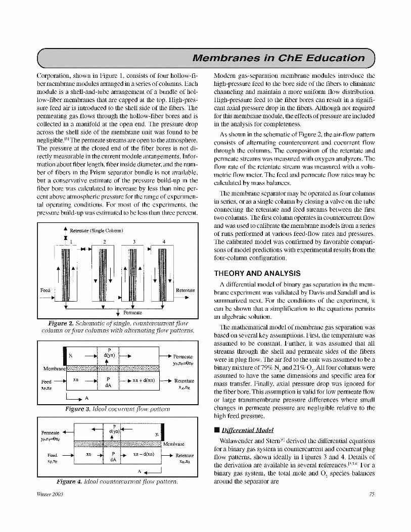
Corporation, shown in Figure 1, consists of four hollow-fiber membrane modules arranged in a series of columns. Each module is a shell-and-tube arrangement of a bundle of hollow-fiber membranes that are capped at the top. High-pressure feed air is introduced to the shell side of the fibers. The permeating gas flows through the hollow-fiber bores and is collected in a manifold at the open end. The pressure drop across the shell side of the membrane unit was found to be negligible. [5J The permeate streams are open to the atmosphere. The pressure at the closed end of the fiber bores is not directly measurable in the current module arrangements. Information about fiber length, fiber inside diameter, and the number of fibers in the Prism separator bundle is not available, but a conservative estimate of the pressure build-up in the fiber bore was calculated to increase by less than nine percent above atmospheric pressure for the range of experimental operating conditions. For most of the experiments, the pressure build-up was estimated to be less than three percent.
Retentate (Single Column)
i Feed 'I
I Retentate
Figure 2. Schematic of single, countercurrent flow column or four columns with alternating flow patterns.
Permeate Yr,ne=0np
Feed Xp,Tip
p
d(yn) i •
p dA
i • xn +d(xn)
Figure 3. Ideal cocurrent flow pattern
p : d(yn)r
xn + d(xn)
y;
Permeate yp,np=0np
Retentate XR,flR
Retentate
Figure 4. Ideal countercurrent flow pattern.
Winter2003
Modem gas-separation membrane modules introduce the high-pressure feed to the bore side of the fibers to eliminate channeling and maintain a more uniform flow distribution. High-pressure feed to the fiber bores can result in a significant axial pressure drop in the fibers. Although not required for this membrane module, the effects of pressure are included in the analysis for completeness.
As shown in the schematic of Figure 2, the air-flow pattern consists of alternating countercurrent and cocurrent flow through the columns. The composition of the retentate and permeate streams was measured with oxygen analyzers. The flow rate of the retentate stream was measured with a volumetric flow meter. The feed and permeate flow rates may be calculated by mass balances.
The membrane separator may be operated as four columns in series, or as a single column by closing a valve on the tube connecting the retentate and feed streams between the first two columns. The first column operates in countercurrent flow and was used to calibrate the membrane models from a series of runs performed at various feed-flow rates and pressures. The calibrated model was confirmed by favorable comparisons of model predictions with experimental results from the four-column configuration.
THEORY AND ANALYSIS
A differential model of binary gas separation in the membrane experiment was validated by Davis and Sandall and is summarized next. For the conditions of the experiment, it can be shown that a simplification to the equations permits an algebraic solution.
The mathematical model of membrane gas separation was based on several key assumptions. First, the temperature was assumed to be constant. Further, it was assumed that all streams through the shell and permeate sides of the fibers were in plug flow. The air fed to the unit was assumed to be a binarymixtureof79% N
2 and21 % O
2.Allfourcolumns were
assumed to have the same dimensions and specific area for mass transfer. Finally, axial pressure drop was ignored for the fiber bore. This assumption is valid for low permeate flow or large transmembrane pressure differences where small changes in permeate pressure are negligible relative to the high feed pressure.
• Differential Model
Walawender and Stem[6J derived the differential equations
for a binary gas system in countercurrent and cocurrent plug flow patterns, shown ideally in Figures 3 and 4. Details of the derivation are available in several referencesP·5
•6
l For a binary gas system, the total mole and 0
2 species balances
around the separator are
75

( Membranes in ChE Education ) n F = nR + np
Xpllp =xRnR +ypnp
(1)
(2)
where nF, nR, and nr are the molar flow rates of the feed, retentate, and permeate streams, respectively, and xF, xR, and xr are the feed, retentate, and permeate 0
2 mole fractions,
respectively. The species balances around a differential volume element in the membrane give
d(xn) = Q'02 (xP-yp)dA (3)
ct[(l- x)n] = Q~J(l- x)P-(1-y)p]dA (4)
where Qj is the permeance of species j, A is the membrane surface area, and P and pare the average retentate and permeate side pressures, respectively.
For convenience in the analysis, Eqs. (1) to (4) were combined into the following dimensionless equations for countercurrent flow:
KR ~j ~ l{cx*(l-x)(xr-y)-x[(l-x)r-(1-y)]} dA lxR -yi)
(5)
KR ~j x-y l{cx*(l-y)(xr-y)-y[(l-x)r-(1-y)]} dA lxR -x)
(6)
KR::: =cx'(xr-y)+(l-x)r-(1-y) (7)
where Y; is the mole fraction in the permeate at the closed end of the fibers. The dimensionless transport parameters are defined as
A* =Al Am (8)
r=P Ip (9)
KR =nR IQN2Amp (10)
a* =Q·o IQ,N 2 2
(11)
n* =nlnR (12)
where Am is the total membrane area. The ideal separation factor, a*, was assumed constant, but the dimensionless transport parameter, KR, was defined as a function of the retentate molar flow rate. The solution to Eq. (7) was used to check the assumptions leading to the algebraic model of the next section. The countercurrent flow equations are integrated from the retentate end of the membrane, subject to the initial conditions
76
x=xRf Y:Yi atA* =0
n =1
Note the discontinuity in Eq. (6) at x = xR requires application of l'H6pital's rule.[6l
(13)
The dimensionless cocurrent flow model equations are
Kp~=( 2.=l'.... l{a*(l-x)(xr-y)-x[(l-x)r-(1-y)]} dA ly-xp)
(14)
Kp dy* =( 2.=l'.... l{a*(l-y)(xr-y)-y[(l-x)r-(1-y)]} dA lx-xp)
(15)
where
(16)
The cocurrent model equations are integrated from the feed end, subject to the initial conditions
X = Xp} * at A = 0 y= Yi
(17)
The permeate composition at the capped end of the hollow fibers is calculated from the ratio ofEqs. (3) and (4)
__l'.i_ a*[xr-yi]
1-yi [(1-x)r-(1-yi)] (18)
where, for countercurrent flow, x = xR. For cocurrent flow, x = xF. Equation (18) is quadratic in Y;· Note that there is an error in the denominators of Eqs. (17) and (22) of the paper by Davis and Sandall_l5l The correct solution to the quadratic equation is
Yi
(a* -l)(xr+l)+r- [(a* -l)(xr+l)+rj2-4(a* -l)a*xr
2( a* - 1) (19)
Davis and Sandall successfully used the differential model in their analysis of O/N
2 separation in the membrane mod
ule. At the time, they found that the background required to solve the model equations for a* and KR was beyond the scope of an undergraduate student in their laboratory course. Consequently, they developed True BASIC programs that were provided to the students to solve the model equations. Since then, advances in computational software (such as Mathcad) have simplified the process of solving the model
Chemical Engineering Education

( Membranes in ChE Education )
equations. Undergraduate students are now able to develop their own solutions using standard numerical methods for solving systems of nonlinear equations or differential equations that are readily available in these computer tools.
Nevertheless, students are still required to set up a standard method such as Euler's or Runge-Kutta for the initialvalue problems in order to find the values for a* and KR by inverse analysis of the first column in countercurrent flow. For example, Mathcad and Polymath do not permit their intrinsic capabilities for solving systems of first-order differential equations to be treated as part of another function. An example of programming required in Math cad for the inverse mass transfer is shown in Figure 5. This type of solution may be intimidating for undergraduate students, depending on their level of experience. This realization, along with the observation that the composition profiles along the membrane were approximately linear, led to the following alternative analysis that avoids the initial-value problem solution requirements entirely.
Xp:=0.21 "R :=0.16 yp:=0.48 r:=6.465 a :=6 KR :=50
(a- 1)-(r·"R + t) + r-J[(a - 1)-(r·"R + 1) + r]2
-4-a-r•"R•(a - 1) yia): ( )
2- a -1
ctx(x,y,KR,a) := .2.. . ..:..::.1...-[(l - x)·a•(r•x- y) - x-[r-(1 - x) - (I - y)J] KR y -"R
dy(x,y,KR,a) := if x= "R
Yin<- Yia)
("R - Yin)·r{ a - Yin·(a - t)]
("R - Yin){(a - 1).{2·Yin - r·"R - 1) - r] KR
ctx( "R• Yin•KR,a)
.2.. . .!:.::..L-[(l -y)•a•(r-x- y) -y-[r·(l - x) - (1-y)J] otherwise KR x-"R
( ) ·- _a·.c.(x_·r_-'-'-y)_+..c.( l_-_x'-) -_('-l _-'-'-y) dn x,y,KR,a .-
KR
f(KR,a) := z0 <- 0
"o t-- I
for jE L.m
Zjf-Zj-l +£l.z
~ t-- xj-l + £l.z-dx(xj-t'Yj-l'KR,o:)
Yi<- yj-l + &z-dyh-1,Yj-l'KR,a)
nj t-- "j-l + Az-dn(xj-l'yj-l'KR,a)
so f- z
<-- Eule~s method
m= 100 l
!:iz;:;m
Solve fora• and Ka
Given
(49.032)
Find(KR, a) = 5.903
Figure 5. Example of Mathcad programming for inverse mass transfer analysis for a* and KR'
Winter2003
• Algebraic Model
Boucif, et al., [7l presented a series solution to the binary component differential model Eqs. (5), (6), (14), and (15) that requires a numerical solution to a pair of third-order polynomial equations. The solution to the series equations agrees with numerical solutions to the differential model when the cut is less than 50%. The series solution does not include axial pressure effects in the feed or permeate gas, however. Hundyil and Koros[81 presented a more complete analysis of hollow-fiber membrane modules for multicomponent gas separation that includes pressure effects. Their approach is based on a finite-volume element model that requires iterative solutions to a large system of nonlinear algebraic equations. The finite-element approach is recommended when detailed information of pressure, temperature, and composition effects is required.
A simpler, alternative analysis of the membrane unit described here was developed that involves only the solution to a small system of nonlinear algebraic equations and includes pressure effects when necessary. The simpler-model equations are analogous to the shell-and-tube heat-exchanger design equations that are familiar to undergradute chemical engineering students. The following analysis assumes laminar flow and constant species permeances that are independent of the pressure and composition of the feed or permeate gas. The Hagen-Poisseuille equation is commonly used to calculate axial pressure effects[9l
dp 128 RT µn - 4 dz pndrNr
(20)
where R is the ideal gas constant, T is the gas temperature, µ is the gas viscosity, n is the variable molar flow rate of permeate gas, dr is the inside fiber bore diameter, and Nr is the number of fibers in a bundle. Other expressions derived from the Hagen-Poisseuille equation have been developed to account for compressibility and flow in porous channels when necessary. [3,10-121
It has been observed that when the change in the feed mole fraction of oxygen is less than 50%, the differential balances may be replaced with algebraic expressions involving the logarithmic mean of the transmembrane partial-pressure differenceY31 In Eq. (3), let
L'i = xP-yp (21)
The driving force for diffusion across the membrane, Li, is assumed to be a linear function of the change in the molar flow on the feed side of the membrane
(xn)R -(xn)F M L'iR -L'ip
(22)
Combine eqs. (2), (3), and (22), separate variables and inte-
77

( Membranes in ChE Education
grate 2 128RTµLnp
)
(23)
or
Ypllp=Q'o2(xP-yp\mAm (24)
where the log-mean difference in 02
partial pressure across the membrane is defined as
( ) (xP-yp)R -(xP-yp)F
xP-ypl = [ ] m £n (xP-yp)R !(xP-yp)F
(25)
A similar result is found for a N2
flux expression
(1-yp )np = Q'N2 [(1-x)P-(1-y)pJim Am (26)
The steady-state binary-gas membrane equations can be written in dimensionless form using the average pressures
Xp=xR(l-0)+yp0 (27)
YpKR0 = (1- 0)a *(xr - y\m (28)
(1-yp )KR0 = (1-0)[(1- x)r -(1-y)Jim (29)
where the cut is defined here as the ratio of permeate-to-feed flow rates
0=np/nr (30)
Alternative forms of Eqs. (28) and (29) in terms of~ are
(1-yp )Kp0 = [(1- x)r -(1-y)Jim
(31)
(32)
The permeate composition at the closed end of the hollowfiber membranes is calculated from Eq. (19).
The experimental separation factor was calculated from the measured compositions of the permeate and retentate streams
Yp(l-xR) a=~,------,- (33)
xR(l-yp)
Under conditions where the change in the feed composition exceeds 50%, the log-mean model can be applied two or more times as necessary across a module such that each cut does not exceed a 50% change in xF from the previous step. The pressure at the closed end of the fiber bore can be calculated by assuming that the permeate flow rate is a linear function of distance along the fiber
n = npz L
(34)
where L is the fiber length. Equation (20) can be integrated with substitution from Eq. (34) to give an estimate for the permeate pressure at the closed end of the fibers[91
78
Pc= p + 4 ndrNr
(35)
• Solution Method
The algebraic model Eqs. (19) and (27-29) represent a system with four degrees of freedom, or four equations in eight variables: xF, xR, yr, Y;, 0, a*, KR, and r. The model was initially calibrated by fixing xF and r and measuring xR and yr, leaving Y;, 0, a*, and KR as unknowns in the solution.
The solution of the system of nonlinear algebraic equations requires an iterative, trial-and-error technique, such as Newton's method. The log-mean approximation of the partial-pressure driving force is notoriously difficult to converge under these circumstances. Fortunately, there are good approximations to the log-mean that avoid problems of divergence in the solution. The following form of the Chen approximation was used:[141
(36)
Floudas noted that the Chen approximation to the log-mean has the advantage that it becomes zero if either the feed or exit partial-pressure driving forces become zeroY51
The four-column configuration requires sequential solution to the countercurrent and cocurrent models. Note that n
2F =
n1R and K
2F = K
1R between the first and second columns, and
that n4F = n3R and K4F = K3R between the third and fourth columns. The feed flow rates to each column are calculated from the cut for the previous column.
RESULTS AND DISCUSSION
The experimental data of Davis and Sandall[51 were used to illustrate the analysis procedure. The assumption ofEq. (22) for the log-mean approximation was evaluated by plotting a representative numerical solution to Eq. (7), shown in Figure 6. A linear least-squares regression of the numerical results
Figure 6. Numerical 0.22
results to support the 0.21
logarithmic- 0.2
mean assumptions for ~ 0.19
XF=Q.21, 0.18
XR=Q.16, 0.17
yP=0.48 r=6.47 0.16
* =5.9 a 0.15
and KR=4900. 0.6 0.65 0.7 0.75 0.8 0.85 0.9
xr-y
Chemical Engineering Education
( Membranes in ChE Education )
shows that the assumption of a linear function for Li is valid for the conditions of this laboratory experiment.
A sample calculation of the single countercurrent flow model calibration using Math cad is shown in Figure 7. The experimental data and results of the algebraic model are compared with the results from the differential model in Table 1 for a* and KR. There are no significant differences in the results between these models.
"F := 0.21 "R := 0.16 Yp := 0.48 r := 6.465
KR :=50 a :=6 Yi:=0.5 e :=0.2
Given
"F = "R·(l - 0) + Yp·0
Yi a•("R·r- Yi)
1 - Yi = ( 1 - xR)·r - ( 1 - Yi)
Yp·KR'0 = (1 - 0)·a·6ini"F•r-yp,"R•r- Yi)
Find(KR,a,yi,e) =[~~
03214
] 0.426
0.156
Figure 7. Example of Mathcad calculation for inverse mass transfer analysis using the log-mean model.
TABLE 1 Calibration Data151 and Results for Single Countercurrent Column
Ex[!.erimental Data Differential Model Al,:.ebraic Model
nRxl02
* * P(kPa) (gmol/s) XR Yr a KR a KR
377 0.73 0.18 0.43 5.81 31.1 5.82 31.1 377 0.74 0.18 0.43 5.81 31.1 5.82 31.1 377 1.03 0.19 0.44 5.98 49.6 5.98 49.6 377 1.32 0.19 0.44 5.98 49.6 5.98 49.6 377 2.54 0.20 0.44 5.71 98.7 5.71 98.6
515 0.62 0.15 0.45 5.93 26.2 5.97 26.1 515 0.73 0.16 0.46 6.02 33.3 6.05 33.2 515 0.95 0.17 0.47 6.12 43.9 6.14 43.9 515 1.51 0.18 0.47 5.85 58.2 5.86 58.2 515 2.25 0.19 0.48 5.96 92.1 5.96 92.1
653 0.74 0.14 0.46 5.78 31.5 5.84 31.4 653 0.95 0.15 0.47 5.84 38.8 5.88 38.7 653 1.32 0.16 0.48 5.90 49.1 5.93 49.0 653 2.18 0.18 0.49 5.73 85.7 5.74 85.6 653 3.44 0.19 0.5 5.81 135 5.81 135
Average 5.88 5.90
Winter2003
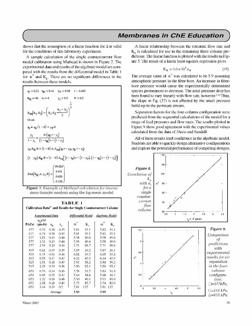
A linear relationship between the retentate flow rate and KR is calculated for use in the remaining three column predictions. The linear function is plotted with the results in Figure 5. The result of a linear least-squares regression gives
(37)
The average value of a* was calculated to be 5.9 assuming atmospheric pressure in the fiber bore. An increase in fiberbore pressure would cause the experimentally determined species permeances to decrease. The axial pressure drop has been found to vary linearly with flow rate, howeverY61 Thus, the slope in Eq. (37) is not affected by the small pressure build-up in the permeate stream.
Separation factors for the four-column configuration were predicted from the sequential calculations of the model for a range of feed pressures and flow rates. The results plotted in Figure 9 show good agreement with the experimental values calculated from the data of Davis and Sandall.
All of these results lend confidence in the algebraic model. Students are able to quickly design alternative configurations and explore the potential performance of competing designs.
140
120
Figure 8.
Correlation of 100
KR 0
with n " " 80
for; single 60
counter- 0 0
current 0 40
flow column 20
0.5 1.5 2 2.5 3 3.5
nR X 1r,i gmol/s
5.5 Figure 9.
Comparison
5 of
predictions with
4.5 experimental
" " results for air 0 separation
4 0
in the four-column
3.5 configura-tion:
3 • =377kPa,
3 3.5 4 4.5 5 5.5 0=515 kPa,
a, 6=653 kPa.
79

( Membranes in ChE Education ) For example, students usually start by comparing the performance of cocurrent and countercurrent flow. This leads to a design for one column operating in countercurrent flow with the same membrane surface area as the four columns. The single column design gives a predicted increase of 10% N
2
recovery when compared to the modular design. Students may use the models to predict a dimensionless membrane area, 1/K, to recover a desired fraction of oxygen fed to the permeator. Other designs include four columns operating in parallel with countercurrent flow or four columns with the feed side in series and the permeate side in parallel.
The Mathcad files used in the analysis are available at <www.d.umn.edu/-rdavis/cee>
CONCLUSIONS A membrane experiment for investigating gas separation
has been in use for over ten years in the undergraduate laboratory at the University of California, Santa Barbara. A simple analysis method was presented that requires only the solution to a system of four algebraic equations. The simpler analysis is equally applicable to newer membrane configurations that introduce the high-pressure feed to the fiber bores in order to maintain better flow patterns in the membrane module. The experimental apparatus was designed to permit single- and four-column investigations of air separation. The single column was used to calibrate the models for binary gas separation. Comparing results for the four-column operation validated the calibrated model. Good model and experimental agreement lend confidence in the model and validate the model assumptions. Students are then able to use the model to develop competing designs for gas separation and optimize their designs for maximizing efficiency of separation. The advantages of the simpler approach are that students can readily set up and solve the model equations without complicated programming. Students are also able to explore alternative designs by building models and comparing the results.
NOMENCLATURE A membrane area, m2
d diameter, m K dimensionless membrane transport parameter L fiber length, m n molar flow rate, gmol/s N number of fibers in a bundle p permeate side pressure, kPa P feed side pressure, kPa Q' permeance, gmol/(s-kPa-m2)
R ideal gas constant, kPa-m3/gmol-K T temperature, K x feed stream mole fraction of oxygen y permeate stream mole fraction of oxygen
80
z variable fiber length, m Greek Symbols
a experimental separation factor ti. transmembrane partial pressure, kPa µ viscosity, N-rn/s 0 cut of feed to permeate stream
Subscripts/Superscripts c closed end of fiber bore e
f F
experimental fiber feed
lm closed end of permeate stream log-mean result membrane nitrogen oxygen predicted retentate
* dimensionless or ideal parameter
REFERENCES 1. Pandey, P., and R.S. Chauhan, "Membranes for Gas Separation," Prag.
Polym. Sci., 26(6), 853 (2001) 2. McCabe, W.L., J.C. Smith, and P. Harriott, Unit Operations of Chemi
cal Engineering, 5th ed., McGraw-Hill, New York, NY (1993) 3. Geankoplis, C., Transport Processes and Unit Operations, 3rd ed.,
Prentice-Hall, Englewood Cliffs, NJ (1993) 4. Seader, J.D., and E.J. Henley, Separation Process Principles, John
Wiley and Sons, New York, NY (1998) 5. Davis, R.A., and O.C. Sandall, "A Membrane Gas Separation Experi
ment for the Undergraduate Laboratory," Chem. Eng. Ed., 25(1), 10 (1991)
6. Walawender, W.P., and S.A. Stern, "Analysis of Membrane Separation Parameters. II: Counter-Current and Cocurrent Flow in a Single Permeation Stage," Sep. Sci., 7(5), 553 (1972)
7. Boucif, N., S. Majumdar, and K.K. Sirkar, "Series Solutions for a Gas Permeator with Countercurrent and Cocurrent Flow," Ind. Eng. Chem. Fund., 23, 470 (1984)
8. Thundyil, M.J., and W.J. Korns, "Mathematical Modeling of Gas Separation Permeators: For Radial Crossflow, Countercurrent, and Cocurrent Hollow Fiber Membrane Modules," J. Mem. Sci., 125, 275 (1997)
9. Zolandz, R.R., and G.K. Fleming, "Design of Gas Permeation Systems," in Membrane Handbook, W.S. Ho and K.K. Sirkar, eds., Van Nostrand Reinhold, New York, NY, p. 66 (1992)
10. Bruining, W.J., "A General Description of Flows and Pressures in Hollow Fiber Membrane Modules," Chem Eng. Sci., 44(6), 1441 (1989)
11. Federspiel, W.J., J.L. Williams, and B.G. Hattier, "Gas Flow Dynamics in Hollow-Fiber Membranes," AIChE J., 42(7), 2094 (1996)
12. Lim, S.P., X. Tan, and K. Li, "GasNapour Separation Using Membranes: Effect of Pressure Drop in Lumen of Hollow Fibers," Chem. Eng. Sci., 55, 2641 (2000)
13. Mulder, M., Basic Principles of Membrane Technology, Kluwer Academic Publishers, Dordrecht, Netherlands (1991)
14. Chen. J.J.J., "Comments on Improvements on a Replacement for the Logarithmic Mean," Chem. Eng. Sci., 42(10), 2488 (1987)
15. Floudas, C.A., Nonlinear and Mixed-Integer Optimization, Oxford University Press, Oxford (1995)
16. Vladisavljevic, G. T., and M. V. Mitrovic, "Pressure Drops and H ydraulic Resistances in a Three-Phase Hollow Fiber Membrane Contactor with Frame Elements," Chem. Eng. Proc., 40, 3 (2001) 0
Chemical Engineering Education