Biodiesel separation through membrane technology
141
CHAPTER ONE 1.0 INTRODUCTION Currently, the concept of biodiesel as a source of energy has been receiving great attention among the futurists and the world policy makers (Kusdiana & Saka, 2001; Lu et al., 2007). This is so because of its renewability, biodegradability, and better quality of exhaust gas emissions. The idea of vegetable oil based fuel to run diesel engines has been on the world stage over a century ago. The discovery of the potential of vegetable oil to serve as fuel was made by one of the most famous scientists of the nineteenth century called “Rudolf Diesel”. Rudolf Diesel, in 1912 stated that ‘‘the use of vegetable oils for engine fuels may seem insignificant today. But such oils may become in course of time as important as petroleum and the coal tar products of the present time’’(Avinash, 2007). Lack in interest to develop the technology of biodiesel fuel over the years was due to availability and low cost of petroleum products (Antunes et al., 2007). However, the renewed and increasing interest in the growth and development of 1
Transcript of Biodiesel separation through membrane technology

CHAPTER ONE
1.0 INTRODUCTION
Currently, the concept of biodiesel as a source of
energy has been receiving great attention among the
futurists and the world policy makers (Kusdiana & Saka,
2001; Lu et al., 2007). This is so because of its
renewability, biodegradability, and better quality of
exhaust gas emissions. The idea of vegetable oil based
fuel to run diesel engines has been on the world stage
over a century ago. The discovery of the potential of
vegetable oil to serve as fuel was made by one of the most
famous scientists of the nineteenth century called “Rudolf
Diesel”. Rudolf Diesel, in 1912 stated that ‘‘the use of
vegetable oils for engine fuels may seem insignificant
today. But such oils may become in course of time as
important as petroleum and the coal tar products of the
present time’’(Avinash, 2007). Lack in interest to
develop the technology of biodiesel fuel over the years
was due to availability and low cost of petroleum products
(Antunes et al., 2007). However, the renewed and
increasing interest in the growth and development of
1

biodiesel fuel is driven mainly by its potential to solve
three main challenges confronting the global economy.
These include amongst others: how to attain energy
independence, reduce environmental impact and achieve fuel
of affordable prices that can compete favourably with the
conventional diesel fuel. Biodiesel fuel in large
quantities could be achieved if certain technologies are
developed. Some of these technologies include: (1)
Establishment of a scheme for the production of low cost
feedstocks. (2) Development of sound technology for the
purification of crude biodiesel. (3) Development of
suitable catalysts that can give higher yields of
biodiesel with less separation and purification
difficulties. (4) Establishment of polices that can
enhance the production of biodiesel fuels. (5) Exploration
and exploitation of biodiesel production systems with the
aim of minimizing energy and water utilization. (6)
Development of technologies to covert by-product glycerol
to added value chemicals (Lu et al., 2007).
In addition environmental concerns that have
drastically increased globally over the past decade due to
global warming effects are among the greatest challenges
2

facing the globe, particularly after the Earth Summit ’92
(Avinash, 2007). Thus, the most viable approach to meet
this rising demands, decrease greenhouse gas emissions and
minimize the effects of fossil fuel depletion is by
exploring alternative renewable energy sources (Guo et
al., 2010; Dias et al., 2012). Biofuels, particularly
biodiesel is such a fuel that shows great potential to
replace petro-diesel (Kafuku & Mbarawa, 2010; Leung et
al., 2010). Biofuels are commonly known to offer several
advantages over fossil fuels such as sustainability,
biodegradability, lower greenhouse gas emissions, regional
development, social structure and agriculture development,
and fuel security supply. Further, replacing petro-diesel
with biodiesel fuel could reduce the accumulation of
greenhouse gases such as CO2 in the atmosphere (Bhatti et
al., 2008). Also biodiesel fuel has been commonly found to
offer engine performance comparable to that of petro-
diesel fuel, whilst reducing engine emissions of
particulates, hydrocarbons and carbon monoxide (Haas et
al., 2006).
Biodiesel fuel is usually produced from virgin and
used vegetable oils and animal fats. Presently several
3

efforts are made to produce biodiesel from microalgae.
Microalgae clearly offer some advantages among other
feedstocks. These advantages include: much higher biomass
productivities than land plants (doubling times may be as
short as 3.5 hrs), some species can accumulate up to 20–
50% triacylglycerols, while no high-quality agricultural
land is necessary to grow the biomass, and even no land at
all, offshore microalgae farming could be a reasonable
alternative (Amaro et al., 2011). Biodiesel fuel can be
produced via direct blending with normal diesel,
microemulsion, pyrolysis and transesterification (Naik et
al., 2010; Zabeti et al., 2009). However,
transesterification reaction is the most adopted
technology for the transformation of fats and oils into
biodiesel fuel (Bhatti et al., 2008). Usually the
triglycerides of fats and oils are transesterified using
short-chain alcohols such as methanol and ethanol in the
presence of alkali catalysts. In addition, acid catalysts
can be used for the transesterification reaction (Harding
et al., 2008; Montefrio et al., 2010).
Recently enzymes are applied as biocatalysts for the
production of biodiesel. Both virgin and used oils and
4

animal fats can serve as feedstock sources for the
production of biodiesel fuel. Biodiesel has been
conventionally produced using batch reactors, plug flow
reactors, and continuous stirred tank reactors. However,
the recent introduction of membrane reactor has remarkably
provided excellent conversions of fats and oils to
biodiesel fuel (Cao et al., 2008a; He et al., 2012). The
membrane reactor is very significant in the production of
biodiesel for its ability to completely block the passage
of unreacted triglycerides to final biodiesel product.
This phenomenon has the benefits of providing high-quality
biodiesel fuel (Cao et al., 2008a). Generally, production
of biodiesel with full conformity to biodiesel
international standard specifications (EN 14214 or ASTM
6751- 07) is technically difficult, especially meeting the
requirements of both biodiesel standards of 99.7wt% methyl
esters (Sandra & Dejan, 2009).
At the end of transesterification, biodiesel is
mostly separated via gravitational settling or
centrifugation. The crude biodiesel is then purified and
dried to meet the stringent international standard
specification provided by EN14214 (Vicente et al., 2007).
5

The production of biodiesel using alkaline catalysts can
provide higher biodiesel yield (>98%), but the process of
biodiesel refining is difficult (Balat & Balat, 2008;
Sharma et al., 2008). This is due to soap formation
associated with alkaline catalysts. Further, the formation
of soap decreases biodiesel yield obtained after the
clarification and separation stages. As well, the
dissolved soap increase the biodiesel solubility in
glycerol, an additional cause of yield loss (Leung, et
al., 2010). However to mitigate the problems faced with
the use of homogeneous alkaline and acid catalysts,
heterogeneous catalysts such as solid and enzymes
catalysts have been developed and used during biodiesel
production process (Chew & Bhatia, 2008).
1.1 Research Problem Statement
Purification of crude biodiesel is necessary so as to
make biodiesel suitable for diesel engines consumption and
other applications. However it was clearly evident from
the literature reviewed that the problems with biodiesel
purification process is associated with the nature of
catalysts, alcohol to oil molar ratio, water and free
6

fatty acid contents. Several attempts have been made in
producing biodiesel using heterogeneous catalyst to
overcome the problems associated with homogeneous catalyst
such as difficulties in biodiesel purification, but so
many issues are yet to be addressed such as reaction rate,
conversion, catalyst leaching, catalyst regeneration, and
reuse. The purification of crude biodiesel is usually
achieved via two notable techniques; wet and dry washings.
Conventionally wet washing is the most employed technique
to remove impurities such as soap, catalyst, glycerol and
residual alcohol etc. from biodiesel. Conventional
purification of these impurities poses challenges. The
major disadvantage in the use of water to purify biodiesel
is increase in cost and production time (Berrios &
Skelton, 2008). Besides, separation of biodiesel phase
from water phase is difficult and produces large amount of
wastewater. For each litre of biodiesel, close to 10
litres of wastewater is produced (Saleh et al., 2010). In
addition biodiesel purification alone accounts for 60 to
80% of the process cost (Tai-Shung, 2007). As a result,
dry washing technique (ion exchange resins and magnesol
powder) was introduced to substitute water washing to
7

remove biodiesel contaminants. This technique is also
employed in commercial plants to purify biodiesel (Cooke
et al., 2003). However, the understanding of the chemistry
of dry washing substances is still skeletal (Mike, 2011).
Furthermore based on the published literature
reviewed, it was found that biodiesel separation and
purification through conventional processes have presented
high-quality biodiesel that can be used on diesel engines
without necessary engine modification. However, issues
such as longer settling time, cost of equipment, high
water and energy consumptions, and lack of regeneration
and reuse of adsorbents have been the main problems
confronting the application of these techniques. These
problems have resulted to the exploration and exploitation
of membrane technology for the purification of biodiesel.
Biodiesel purification via membranes have so far provided
promising results, in addition to less water utilization
(Low & Cheong, 2009.). Membrane biodiesel purification
processes are very good in providing high-quality
biodiesel fuel (Baroutian et al., 2011). Besides membrane
processes are more economical compared to classical
processes. Further, a large portion of membrane separation
8

processes are carried out under reasonable temperature and
pressure conditions, and also the implementation of their
scale-up are less cumbersome. Additionally, membranes are
generally most preferred in the refining processes for the
following reasons: low energy consumption, safety, simple
operation, elimination of wastewater treatment, easy
change of scale, higher mechanical, thermal and chemical
stability, and resistance to corrosion. Use of ceramic
membranes in biodiesel production, separation and
purification is fast growing due their stability in
organic solvents. Also, apart from the ability to
withstand the reaction conditions, chemical and thermal
stability also allows the ceramic carbon membrane to be
cleaned more proficiently when unrefined feedstocks such
as used/waste cooking oils are employed (Cao et al.,
2008b; Ochoa et al., 2001; Sarmento et al., 2004).
In all the previous researches conducted, the lowest
membrane pore size studied was 0.05µm. In addition most of
the studies focused only on single impurity retention. To
the best of our knowledge there is no research so far
conducted on the purification of crude biodiesel using
membrane with pore size of 0.02µm. In addition no
9
optimization study was carried on both membranes (0.02µm
and 0.05µm). Also no research conducted on the comparison
between the efficiencies of water washing, dry washing and
membrane separation for the purification of crude
biodiesel.
1.2 Research Approach
Presently separation and purification of biodiesel
using membrane technology is new. Nonetheless, current
investigations have shown the effectiveness of membrane
technology for the production of biodiesel (Cao et al.,
2008a; Dubé et al., 2007). Membrane separation technology
has been effectively employed in numerous applications,
such as gas separations, protein separations and water
purification. This technology has not being investigated
to a great extent in the separation and purification of
biodiesel. Membrane technology presents a great propensity
toward providing solutions to environmental problems by
recovering valuable products as well as treating effluents
and minimizing their harm to the atmosphere. The most
broadly employed membrane processes are membrane micro-
filtration (MF) and ultrafiltration (UF) pressure-driven
10

processes capable of separating particles in the
approximate size range of 0.1–10 µm and 1–100 nm,
respectively (Montefrio et al., 2010). Typically, UF will
remove high molecular weight substances, colloidal
materials, and organic and inorganic molecules (Saleh et
al., 2011). Membrane separation system is defined by the
nature of its material and type. Further, optimum membrane
performance is influenced by choice of adequate membrane
material. The membrane separation processes are made by
different kinds of membranes which could either be
polymeric or ceramic. The polymeric membranes include
amongst others: polyvinylidene fluoride (PVDF),
polysulfone, polyamide, and polycarbonate. Some of these
polymers can appreciably influence the efficiency,
maintenance characteristics and membrane performance. In
this study, ceramic membrane was selected because of its
numerous advantages over polymeric membrane. These
advantages include; structural stiffness and enhanced
mechanical strength, chemical and thermal resistance,
corrosion resistance, stability of operating
characteristics, resistance to bacterial attack and
chances of numerous regenerations. These defined
11

characteristics make separation of solutions under adverse
conditions such as corrosive media, higher pressures (1–10
MPa), higher temperatures and wide range of pH values (0–
14) to be possible. Additionally, ceramic membranes are
made from materials such as oxides of zirconium, titanium
and aluminum (Komolikov & Blaginina, 2002).
In this study, ceramic membranes with pore sizes of
0.02µm and 0.05µm were used to purify crude biodiesel
without water wash steps. As well as studying the effects
of process operating parameters such as transmembrane
pressure, flow rate and temperature on the performance of
the membranes. Further, rigorous optimization using
central composite design (CCD) coupled with Response
Surface Methodology (RSM) was separately performed on the
membranes for the simultaneous retention of glycerol, soap
and catalyst. In addition comparison between the membrane
process, water washing (acidified water), and dry washing
(magnesol) for the removal of free glycerol, soap, and
catalyst (potassium) from crude biodiesel toward biodiesel
quality were also carried out.
1.3 Aims and Objectives of the Research Study
12

The main aims and objectives of this research work
are:
i. To set up a laboratory scale membrane system for
the purification of crude biodiesel.
ii. To study the influence of process operating
parameters on the membrane performance during
separation and purification of crude biodiesel.
iii. To optimize the membrane process parameters in
terms of biodiesel purity using the Design of
Experiments approach.
iv. To compare the performance of the developed
membrane system in terms of the quality of
biodiesel product to the conventional biodiesel
purification processes such as biodiesel wet
washing and dry washing.
1.4 Thesis Outline
The thesis consists of the following chapters:
1.4.1 Chapter one: This chapter describes the
introductory aspect of the work comprising of the
research problem statement, research approach and the
research objectives.
13

1.4.2 Chapter two: This chapter discusses the reviewed
literature comprising of biodiesel production
processes, purification processes and the
friendliness of biodiesel to the environment.
1.4.3 Chapter three: This chapter provides the
methodology adopted. It comprises biodiesel
production process, membrane purification process and
the techniques used to analyse the initial and the
final concentrations of the contaminants in
biodiesel.
1.4.4 Chapter four: This chapter describes the results
obtained from biodiesel water washing, dry washing
through magnesol and purification through membrane.
The effects of process parameters on membrane
separation for the purification of biodiesel are
discussed. Furthermore the optimization of the
process parameters is also reported.
1.4.5 Chapter five: This chapter discusses the
conclusions derived from the research work conducted
and the recommendations for the future work.
1.4.6 Appendix: This part presents the journal
articles published, articles under review process and
14

the papers presented at national/international
conferences.
15

CHAPTER TWO
2.0 LITERATURE REVIEW
2.1 Biodiesel as Diesel Engine Fuel
Biodiesel is an important alternative vehicular fuel.
It has excellent properties as diesel engine fuel, so it
can be used in compression-ignition diesel engines (Kent
Hoekman et al., 2012). Biodiesel can be derived from
several different vegetable oils or animal fats feedstock.
Vegetable oil and animal fat direct use as fuel in diesel
engines is limited due to two main factors; low volatility
and high viscosity. Traditional processing involves an
alkali-catalyzed process, but this process is difficult
for lower cost high free fatty acid feedstock due to soap
formation. Pre-treatment of the feedstock with high free
fatty acid using strong homogeneous acid catalysts such as
sulfuric acid have been shown to provide reasonable
conversion rate, higher yields and high-quality biodiesel
final products. These technologies have played a vital16

role in ensuring the production of biodiesel from
feedstock like soap-stock that are normally regarded as
waste. Biodiesel is now mainly being produced from
rapeseed, cottonseed, soybean, canola and palm oils
(Demirbas, 2008; Demirbas and Demirbas, 2011). Furthermore
Demirbas (2009) stated that the higher heating values
(HHVs) of biodiesels are relatively high. The values of
HHVs of biodiesels ranged from 39–41 MJ/kg and are
slightly lower when compared to those of gasoline (46
MJ/kg), petro-diesel (43 MJ/kg), or petroleum (42 MJ/kg),
but greater than coal (32–37 MJ/kg). Further almost all
types of vegetable oils can be used to replace the diesel
oil; however the rapeseed oil and palm oil can be the most
suitable vegetable oils which can be used as diesel fuel,
additive or diesel fuel extender. Biodiesel termed as
clean fuel does not contain carcinogenic substances and
its sulfur content is also lower than its content in
petro-diesel. The ability of biodiesel to be highly
biodegradable and its superb lubricating property when
used in compression-ignition diesel engines makes it to be
an excellent fuel. Also its renewability and similarities
in physicochemical properties to petro-diesel, revealed
17

its potential and practical usability as fuel for the
replacement of petro-diesel in the nearest future. More
so, few other physical and chemical properties of
biodiesel fuel are of great concern and require to be
enhanced to make it fit for use in clean form (i.e. 100%
biodiesel). These properties include among others; engine
power, increase in calorific value, reduced emission of
nitrogen oxides (NOx), and low temperature properties
improvement. Furthermore methyl esters can improve the
lubrication properties of the diesel fuel blend. Biodiesel
decrease long term engine wear in compression-ignition
diesel engines. Biodiesel is a good lubricant and is about
66% better than petro-diesel. Its oxidation stability
improvement is also important to prevent it from
deteriorating when stored over time. Currently biodiesel
is compatible in blended form with petro-diesel in the
ratio 20 (biodiesel): 80 (mineral diesel). Biodiesel has
also being in use in many countries such as United States
of America, Malaysia, Indonesia, Brazil, Germany, France,
Italy and other European nations (Demirbas, 2009).
Biodiesel as an alternative to diesel fuel could only
be successfully used in compression-ignition diesel18

engines, if its physical and chemical properties conform
to the international standard specifications of biodiesel.
These standards (ASTM 6571-3, EN 14214) describe the
minimum requirement that must be met before biodiesel is
used as a pure fuel or blended with petroleum-based diesel
fuel. Biodiesel fuels are characterized by their cetane
number, density, viscosity, cloud and pour points, flash
point, copper corrosion, ash content, distillation range,
sulfur content, carbon residue, acid value, free glycerine
content, total glycerine content and higher heating value
(HHV) etc. The viscosity values of vegetable oils
decreases sharply after transesterification reaction.
Further the flash point values of fatty acid methyl esters
(FAME) are significantly lower than those of vegetable
oils. Also high regression between the density and
viscosity values of vegetable oil methyl esters and a
considerable regular relationship between viscosity and
flash point of vegetable oil methyl esters has been
established (Balat & Balat, 2008; Demirbas, 2009).
Transesterification reaction converts triglycerides
into methyl or ethyl esters and reduces the molecular
weight to one third that of the triglyceride and decreases19

the viscosity of vegetable oils by a factor of about
eight. The viscosities of biodiesel fuel from animal fats
such as lard and tallow show the same trends as
temperatures, higher than the soybean and rapeseed
biodiesel fuels. Virgin and waste vegetable oils can be
used as fuel for compression-ignition diesel engines, but
their viscosity is much higher than that of common diesel
fuels and this requires major diesel engines
modifications. Also the burning of vegetable oils in
diesel engines is not clean resulting to the formation of
unwanted materials such as acrolein and organic acid.
These materials lead to significant negative effects on
the performance and longitudinal engine durability.
However vegetable oils can be converted into their fatty
acid methyl esters by transesterification reaction and can
be convertibly used as fuels for diesel engine
applications without major modifications (Atapour &
Kariminia, 2011; Balat & Balat, 2008; Canakci & Gerpen,
1999; Alexandre et al., 2012).
2.2 Biodiesel Economic and Environmental Analysis
2.2.1 Biodiesel Economic Analysis
20

Biodiesel can reduce country’s over-reliance on the
importation of crude oil imports. It also supports
agricultural activities by providing a new labour and
market opportunities for domestic crops. And it is broadly
accepted by vehicle manufacturers (Demirbas, 2003). The
statistic of world biodiesel production revealed, 42% of
the global total in 2006 was accounted for by Germany,
where market conditions were favourable. Other countries
with major biodiesel markets in 2006 included United
States, France, Italy, and the United Kingdom (Balat &
Balat, 2008). Currently, soybean oil, alkaline catalyst
and short-chain alcohol, methanol are used to produce
biodiesel, however the huge quantities of less cost fats
and oils such as animal fats and restaurant wastes that
could be converted to biodiesel have lessen the problems
faced in using soybean oil as feedstock for biodiesel
production. Furthermore the costs of biodiesel from
oilseed or animal fats have been projected by economic
feasibility. The costs ranged from US$0.30–0.69/l,
including meal and glycerine credits and the assumption of
reduced capital investment costs by having the crushing
and/or esterification facility added onto an existing
21

grain or tallow facility. Biodiesel cost from waste grease
and vegetable oil are roughly projected to be US$0.34–
0.42/l and US$0.54–0.62/l respectively (Wen et al., 2009).
Presently, biodiesel is not economically realistic,
therefore more development in research and technology will
be required because of pre-tax diesel priced at US$0.20–
0.24/l in some European countries and US$0.18/l in the
United States (Demirbas, 2009). More so, if less expensive
feedstocks are used to produce biodiesel, a 25 per cent
reduction in cost production is possible (all other
production costs kept equal). Also, approximate
projections of the cost of biodiesel fuel produced from
vegetable oil and waste grease are US$0.54±0.62/l and
US$0.34±0.42/l respectively. Further, biodiesel from palm
oil costs around $0.66/L or 35% higher than petroleum
diesel. This suggests converting palm oil to biodiesel
fuel adds about $0.14/L to the price of the oil. As well
for biodiesel from palm oil to be competitive with petro-
diesel, the price of palm oil should not go beyond
$0.48/L, assuming no tax on biodiesel. By means of similar
equivalence, a considerable target price for microalgal
oil is $0.48/L, for algal-derived diesel fuel to be cost
22

competitive with petroleum diesel ( Canakci, 2007; Balat &
Balat, 2008; Demirbas, 2009; Demirbas & Demirbas, 2011).
Furthermore Haas et al. (2006) carried out economic
analysis to produce biodiesel by using low value
triglycerides as feedstocks. It has been suggested that
vegetable oil soap-stock used in producing biodiesel would
nearly cost US$ 0.41/l, a 25% reduction relative to the
estimated cost of biodiesel produced from soy oil (Fan and
Burton, 2009). Biodiesel production cost was reported to
vary inversely and linearly with variations in the market
value of glycerol, increasing by US$0.0022/l ($0.0085/gal)
for every US$0.022/kg ($0.01/lb) decrease in glycerol
value. The model is flexible in that it can be modified to
calculate the effects on capital and production costs of
changes in feedstock cost. So also the changes in process
chemistry and technology, the changes in the type of
feedstock employed, and changes in the value of the
glycerol co-product (Haas et al., 2006). Besides the cost
of feedstocks which contributes to high cost of biodiesel
compared to petro-diesel, the major limiting factor to
biomass use is the technology development for the
separation, purification, and its transformation into
23

biochemicals and biofuels (Tai-Shung, 2007). Consequently,
purification of biodiesel via membrane is envisaged to
benefit from low cost membrane process.
2.2.2 Biodiesel Environmental Consideration
Presently great attention is given to production of
biodiesel due to its environmental friendliness, providing
low emissions compared to non-renewable petro-diesel
fuels. Over a century ago, vegetable oil was tested by
Rudolf Diesel on his combustion engine. Due low prices of
fossil fuels interest in research on vegetable oils was
low at that time. The current fossil fuel price hike and
increase in environmental concerns due to greenhouse gas
emissions (e.g., carbon dioxide) have reignited scientists
and Engineers to concentrate on the development of
vegetable oils and their derivatives as substitute fuel
sources. The use of vegetable oil and its derivative has
the ability to reduce the concentration of pollutants and
carcinogens in our environment (Fukuda et al., 2001; Ma &
Hanna, 1999). Further, in 28 days, biodiesel can be
biodegraded by 95% compared to petro-diesel that can only
be degraded by only 40%. As well, compared to petro-
24
diesel, biodiesel combustion emissions, such as unburned
hydrocarbons, carbon monoxide, particulates, SOx emissions
and soot are much lower. In addition a slight increase in
NOx emissions can be positively influenced by delaying the
injection timing in engines. Similarly, a substantial
reduction in the total particulate matter (32%), SOx (8%),
and CO (35%), relative to petro-diesel was reported by
Demirbas (2009).
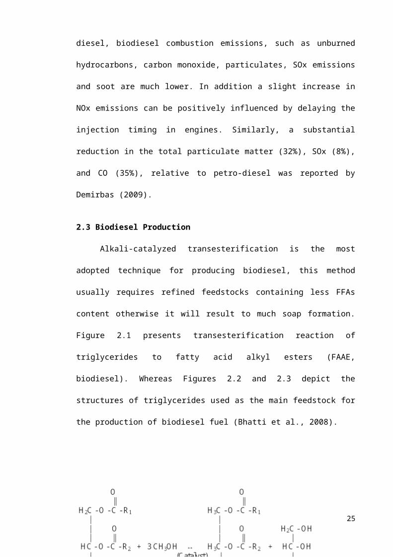
2.3 Biodiesel Production
Alkali-catalyzed transesterification is the most
adopted technique for producing biodiesel, this method
usually requires refined feedstocks containing less FFAs
content otherwise it will result to much soap formation.
Figure 2.1 presents transesterification reaction of
triglycerides to fatty acid alkyl esters (FAAE,
biodiesel). Whereas Figures 2.2 and 2.3 depict the
structures of triglycerides used as the main feedstock for
the production of biodiesel fuel (Bhatti et al., 2008).
25

For alkali-catalyzed transesterification, if the
feedstocks contains high amount of FFAs then it has to
undergo pre-treatment steps before transesterification is
carried out (Leung et al., 2010). Ramadhas et al. (2005)
recommended the acid value of feedstocks to be less than
4.0mg KOH/g before performing alkaline
26
Figure 2.1: Transeterification of vegetable oil with
methanol

transesterification. Although Canakci & Gerpen (1999)
stated that before alkali-catalyzed transesterification is
performed, the acid value of a feedstock has to be 2.0 mg
KOH/g. Nonetheless, the use of heterogeneous catalysts in
biodiesel production has reduced the effects of using low
quality feedstocks, especially enzymes catalysts that has
the potential of converting FFAs into biodiesel, besides
high purity by-products.
2.3.1 Feedstocks for Biodiesel Production.
Biodiesel production is achieved via different kinds
of feedstocks. The nature of feedstock used is dependent
on the geographical position and climate of the place. For
instance Europe employs sunflower and rapeseed oils, palm
oil predominates in tropical countries, soybean oil in
United States and canola oil in Canada (Cao et al.,
2008a). The major feedstocks employed in producing
biodiesel are cotton seed, palm oil, sunflower, soybean,
canola, rapeseed, and Jatropha curcas (Singh & Singh,
2010). Additionally, Zhang et al. (2003) remarked that
employing feedstocks such as waste frying oils, non-edible
oils, and animal fats, as feedstocks could be useful in
27

producing biodiesel. Even though, Banerjee & Chakraborty
(2009) stated that FFAs contents in the waste cooking oil
should be kept within certain limit (<0.5<3) for reaction
involving both acid- and alkali-catalyzed
transesterification reactions. Otherwise these substances
may cause severe difficulties in the refining of biodiesel
products. The cost of feedstocks decreases as FFAs
content increases. In case of industrial biodiesel
production, there is need for low-cost (high FFAs)
feedstocks such as used cooking oils, waste cooking oils,
and non-edible vegetable oils to be used, since biodiesel
fuels from refined oils are costly when compared to petro-
diesel fuel. Besides, application of such feedstocks in
biodiesel production could minimize competition between
demand of edible vegetable oils and cost of biofuel
(Zabeti et al., 2009). As well, application of vegetable
oils as sources of biodiesel requires great efforts to
either develop more productive plant species with a high
yield of oil or to increase oilseeds’ production.
Furthermore, many studies have reported microalgal oil as
feedstock for producing biodiesel. Demirbas (2010) noted
that microalgal oil is the only feedstock that can meet
28

the global demand for transport fuels. The author also
reported that soon microalgal oil will become the most
important feedstock for biofuel production. In addition
microalgae feedstocks are receiving great attention as
sources of energy because of their quick growth potential
coupled with reasonably high lipid, carbohydrate and
nutrients contents. In another study, Demirbas & Demirbas
(2011) highlighted that microalgae possess much quicker
growth-rates than terrestrial crops. The author noted the
per unit area yield of oil from algae is estimated to be
from 20,000 to 80,000 l per acre, per year. In deed this
is 7–31 times more than the next best crop, palm oil. Also
to highlight the significance of microalgae as feedstock
for biodiesel production, Tran et al. (2010) have reviewed
biodiesel production via microalgal oil. The authors noted
that catalysts such as acid, base and zeolites catalysts
can be used in catalyzing transesterification involving
microalgal oil as feedstock. Table 2.1 presents biodiesel
production through different feedstocks.
29
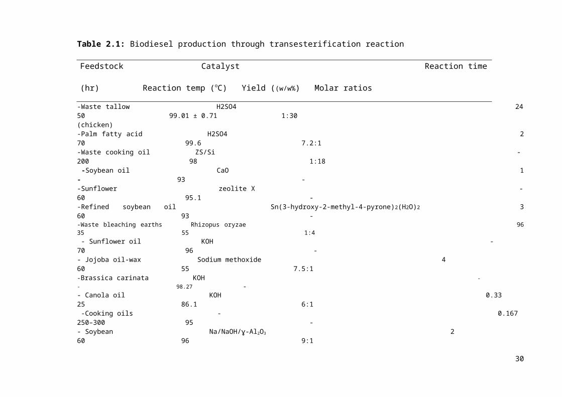
Table 2.1: Biodiesel production through transesterification reaction
Feedstock Catalyst Reaction time
(hr) Reaction temp (oC) Yield ((w/w%) Molar ratios
-Waste tallow H2SO4 2450 99.01 ± 0.71 1:30 (chicken)-Palm fatty acid H2SO4 270 99.6 7.2:1 -Waste cooking oil ZS/Si -200 98 1:18 -Soybean oil CaO 1- 93 - -Sunflower zeolite X -60 95.1 - -Refined soybean oil Sn(3-hydroxy-2-methyl-4-pyrone)2(H2O)2 360 93 - -Waste bleaching earths Rhizopus oryzae 9635 55 1:4 - Sunflower oil KOH - 70 96 - - Jojoba oil-wax Sodium methoxide 4 60 55 7.5:1 -Brassica carinata KOH - - 98.27 - - Canola oil KOH 0.33 25 86.1 6:1 -Cooking oils - 0.167 250–300 95 - - Soybean Na/NaOH/ɣ-Al2O3 2 60 96 9:1
30
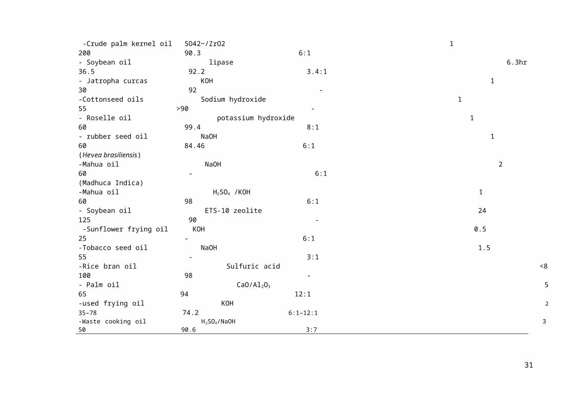
-Crude palm kernel oil SO42−/ZrO2 1 200 90.3 6:1 - Soybean oil lipase 6.3hr 36.5 92.2 3.4:1 - Jatropha curcas KOH 1 30 92 - -Cottonseed oils Sodium hydroxide 1 55 >90 - - Roselle oil potassium hydroxide 1 60 99.4 8:1 - rubber seed oil NaOH 1 60 84.46 6:1 (Hevea brasiliensis) -Mahua oil NaOH 2 60 - 6:1 (Madhuca Indica) -Mahua oil H2SO4 /KOH 1 60 98 6:1 - Soybean oil ETS-10 zeolite 24 125 90 - -Sunflower frying oil KOH 0.5 25 - 6:1 -Tobacco seed oil NaOH 1.5 55 - 3:1 -Rice bran oil Sulfuric acid <8100 98 - - Palm oil CaO/Al2O3 565 94 12:1 -used frying oil KOH 235–78 74.2 6:1–12:1 -Waste cooking oil H2SO4/NaOH 350 90.6 3:7
31

2.3.2 Biodiesel Production via Homogeneous Catalysts
2.3.2(a) Biodiesel Production via Homogeneous Alkaline
Catalysts
Application of alkali-catalyzed transesterification
reaction provides faster rate, nearly 4000 times faster
than that catalyzed by the same amount of an acid catalyst
(Fukuda et al., 2001). Some of the alkaline catalysts used
for the transesterification reaction include among others;
NaOH, KOH, and sodium methoxide. Other alkaline catalysts
include; sodium ethoxide, potassium methoxide, sodium
propoxide, sodium butoxide and carbonates. Based on
biodiesel yield, CH3ONa or CH3OK are better and more
suitable catalysts than NaOH and KOH. Thus, CH3ONa and
CH3OK are more suitable due to their ability to dissociate
into CH3O- and Na+ and CH3O-and K+ respectively. Besides, the
catalysts do not form water during transesterification
reaction (Sharma et al., 2008). Transesterification of
refined oils with less than 0.5 wt% FFAs via chemical
catalysts could lead to high-quality biodiesel fuel with
better yield within short time of 30–60 min (Wang et al.,
2007). Furthermore, Vicente et al. (2004) have compared
different basic catalysts (sodium hydroxide, potassium32

hydroxide, sodium methoxide and potassium methoxide,) to
produce biodiesel fuel using sunflower oil. The reactions
were conducted at a temperature of 65oC, methanol to oil
molar ratio of 6:1 and basic catalyst by weight of
vegetable oil of 1%. They achieved 85.9 and 91.67 wt%
yield of esters for NaOH and KOH and 99.33 and 98.4 6 wt%
yields of esters for CH3ONa and CH3OK respectively. The
authors recorded 98 wt% yields of esters for methoxides
after separation and purification steps were completed.
Further, less yield losses and negligible ester
dissolution in glycerol were observed with methoxides
compared to hydroxides. Rashid et al. (2008) used alkali
catalyst to produce sunflower oil methyl esters. They
reported notable yield of 97.1wt% at 60oC. In addition,
alkaline catalysts concentrations ranging from 0.5–1wt%
could yield 94–99wt% conversion of vegetable oils to alkyl
esters. However, increase in catalyst concentration above
1wt% does not increase the conversion but could add to
extra costs of production. Since, it is essential to
remove the catalyst from the products after the reaction
is completed (Avinash, 2007).
33

2.3.2(b) Biodiesel Production via Homogeneous Acid
Catalysts
The most notable acids commonly employed in
transesterification reaction include among others;
sulfuric acid, sulfonic acid, hydrochloric acid, organic
sulfonic acid, and ferric sulphate (Leung et al., 2010).
Among these acids, hydrochloric acid, sulfonic acid and
sulfuric acid are usually favoured as catalysts for the
production of biodiesel. Brønsted acids preferably
sulfuric acid or sulfonic acid is used to catalyze the
reaction. Although the catalysts give high yield of
biodiesel, but the reaction rates are slow. The alcohol to
oil molar ratio is the main factor influencing the
reaction. Therefore addition of excess alcohol speeds up
the reaction and favours the formation of biodiesel
products. The steps involved during acid-catalyzed
transesterification are: (1) initial protonation of the
acid to give an oxonium ion (2) The oxonium ion and an
alcohol undergo an exchange reaction to give the
intermediate (3) and this in turn can lose a proton to
become an ester. Reversibility of each of the above step
is possible but the equilibrium point of the reaction is
34

displaced in the presence of excess large alcohol, by
allowing esterification to advance to completion
(Demirbas, 2009). Leung et al. (2010) reported that
esterification by acid-catalysis makes the best use of the
FFAs in the animal fats and vegetable oils and converts
them into fatty acid alkyl esters. The authors noted that
one-step esterification pre-treatment may not reduce the
FFAs efficiently, if the acid value of the oils or fats is
very high. This is because of the high content of water
produced during the reaction. In this case, addition of
mixture of alcohol and sulphuric acid into the oils or
fats three times (three-step pre-esterification) is
required. The time needed for this process is about 2hrs
and removal of water is necessary by a separation funnel
before adding the mixture into the oils or fats for
esterification again. Additionally, Soriano Jr et al.
(2009) studied transesterification of canola oil to
produce biodiesel via homogeneous Lewis acid (AlCl3 and
ZnCl2) as catalyst. The reaction occurred in a round bottom
flask submerged in an oil bath equipped with a reflux
condenser, temperature controller and a magnetic stirrer.
The authors reported use of variable parameters such as:
35
reaction time (6,18,24hr), methanol to oil molar ratio
(6:1, 12:1, 24:1, 42:1 and 60:1), reaction temperature
(75,110oC). And tetrahydrofuran (THF) as co-solvent (1:1
methanol to THF by weight in runs with THF), and catalyst
(AlCl3 or ZnCl2). In all the runs, the catalyst amount was
kept at 5% based on the weight of oil. 1H NMR monitored
converting canola oil into fatty acid methyl esters. Thus
the best conditions with AlCl3 were 24:1 molar ratio at
110oC and 18hr reaction time with THF as co-solvent
provided a conversion of 98%. AlCl3 was far more active
compared to ZnCl2 due to its higher acidity.
2.3.3 Biodiesel Production via Heterogeneous Catalysts
Despite the problems surrounding alkali-catalyzed
transesterification, the process is still favourable in
producing biodiesel fuel. The main reason is due to their
faster kinetic rate and economic viability (Wang & Yang,
2007). Several researches were conducted on heterogeneous
catalysts with the aim of finding solutions to the
problems caused by using homogeneous catalysts in
producing biodiesel (Chew & Bhatia, 2008). As a result a
good number of heterogeneous catalysts were explored and
many of the catalysts have displayed very good catalytic36

performances. Some of these catalysts include among
others; oxides, hydrotalcides, and zeolites. Currently,
majority of heterogeneous catalysts used in producing
biodiesel are either oxides of alkali or oxides of
alkaline earth metals supported over large surface area
(Zabeti et al., 2009). In addition, biodiesel is
commercially produced using heterogeneous catalyst through
the Esterfip-H process. This biodiesel process is
commercialized by Axens. The process requires neither
catalyst recovery nor aqueous treatment steps, which are
major bottlenecks from the current homogeneous catalytic
processes. Additionally the Esterfip-H process displays
high biodiesel yields and directly produces salt-free
glycerol at purities exceeding 98% compared to 80%
glycerol purity from homogeneous catalyzed process (Semwal
et al., 2011).
Moreover, Semwal et al. (2011) reported that many
studies on solid acidic catalysts for producing biodiesel
were carried out, however lower reaction rates and
unfavorable side reactions have limited their use. The
authors noted that a good number of investigations on
basic heterogeneous catalysts were also conducted but
37

their activity gets degraded in the presence of water.
They stated that acid–base catalysts are among the most
promising catalysts to employ in biodiesel production;
this is because they can catalyze both esterification and
transesterification simultaneously. Lee & Saka (2010)
reported simultaneous esterification and
transesterification of waste cooking oil using solid
catalyst ZnO– La2O3, which combines acid (ZnO) and base
sites (La2O3). Although the process provided high
conversion of 96% in 3hrs, but like zirconia, lanthanum is
a rare and expensive metal, therefore cost of the catalyst
would prohibit it high use in the production of biodiesel.
Furthermore gelular resin catalysts having covalently
bound sulfonic groups are developed and employed to
simultaneously esterify and transesterify variety of
feedstocks including beef tallow and soybean oil of high
acid number. The authors noted that the key factors
influencing the feasibility and performance of solid
catalysts are durability, catalytic activity and cost of
production. Therefore the main challenges to R&D in using
solid catalyst in the production of biodiesel are
exploring the impacts of those chemical properties of
38

supports on the catalytic activity, and designing
specifically tailored deactivation–prevention and/or
renewal techniques for each catalyst and developing less
expensive supports.
2.3.3(a) The Effects of Solid Alkaline Catalysts on
Biodiesel Production
In recent times there is a great development in the
preparation of solid alkaline catalysts for producing
biodiesel. Solid alkaline catalysts such as CaO provides
many advantages for instance higher activity, long
catalyst life time, and could run under moderate reaction
conditions (Kouzu et al., 2008). Antunes et al. (2007)
noted that like homogeneous catalysts, solid alkaline
catalysts present more catalytic activity than solid acid
catalysts.
Kouzu et al. (2008) produced biodiesel via solid
base-catalyzed transesterification at a reaction time of
1hr and obtained esters yield of 93wt% for CaO, 12wt% for
Ca(OH)2, and 0% for CaCO3. The authors stated that CaO will
39

provide good productivity as NaOH as well as easy recovery
of products and environmental benignity. They used CaO to
transesterified waste cooking oil with an acid value of
5.1 mg-KOH/g. The yield of esters was above 99% at a
reaction time of 2hrs. But a portion of the catalyst
transformed into calcium soap. Thus, solving this problem
will entail removal of FFAs before transesterification
reaction. The authors also noted that due to
neutralization reaction of the catalyst, concentration of
calcium in the produced biodiesel increased from 187 ppm
to 3065 ppm. Conversely, Lim et al. (2009) noted that
transesterification reaction involving CaO requires longer
reaction time. But the benefits gained from the process
such as elimination of neutralization process, less waste
generation and prospect of catalyst reusability
compensates the delay. The authors also achieved biodiesel
purity of 98.6 ± 0.8% within 2.5hrs. Besides for CaO
catalyst, the process generated 90.4% biodiesel yield
compared to biodiesel yield of 45.5% for NaOH and 61.0%
for KOH catalysts. Furthermore, it was observed that
compared to biodiesel yield of 80% under anhydrous
conditions using CaO, addition of 2.03 wt.% water into the
40

reaction medium of 8 wt.% catalysts, 12:1 alcohol/oil
molar ratio and at 3hr of reaction time, could provide
biodiesel yield above 95%. Besides the catalyst active
sites were found not to leach and the activity of the
catalyst was stable after 20 cycles of the reaction.
Moreover, Zabeti et al. (2010) optimized biodiesel
yield produced using transesterification of palm oil via
CaO/Al2O3. They used a 150 ml glass jacketed reactor
equipped with a water-cooled condenser and a magnetic
stirrer (1000 rpm) to perform the experiments for 5hrs.
The estimated optimal reaction conditions achieved were;
reaction temperature of 65°C, catalyst content of 6 wt%
and alcohol/oil molar ratio of 12:1, and achieved a
corresponding yield of 98.64wt%. The authors reported that
the values achieved from ICP-MS showed little leaching of
CaO/Al2O3 active species into the reaction medium and the
catalyst was successfully reused for two successive
cycles. To further examine the potential of solid alkaline
catalysts, different heterogeneous catalysts such as
K2CO3/γ-Al2O3,Na2CO3/γ-Al2O3,LiOH/γ-Al2O3,NaOH/γ-Al2O3, γ−Al2O3,
and KOH/γ-Al2O3 were used providing biodiesel yield of
89.40%.
41

Furthermore, hydrotalcites materials are receiving
great attention because they can be applied as precursors
and as catalyst. Hydrotalcite-like compounds (HTlcs) are a
category of anionic and basic clays referred as layered
double hydroxides (LDH) with the formula
Mg6Al2(OH)16CO3.4H2O. Thus production of biodiesel was
experimented using different hydrotalcites such as
activated Mg–Al hydrotalcites. Xie et al. (2006) have
synthesized fatty acid methyl esters from vegetable oil
with methanol catalyzed by Li-doped magnesium oxide
catalysts. A number of Li-doped MgO samples were prepared
by the incipient wetness impregnation with the Li/Mg molar
ratio in the range of 0.02–0.15. The catalyst weight was
varied in the range of 3–15 wt% (methanol/oil molar ratio
of 12, temperature of 338 K, residence time of 2 hrs). The
results showed that the formation of strong base sites was
principally promoted by adding Li. This results to an
increase of fatty acid methyl esters synthesis.
In addition, Suppes et al. (2004) have
transesterified soybean oil with zeolites (ETS-10 zeolite,
NaX faujasite zeolite) and metal catalysts. The
transesterification reaction was performed at 6:1 molar
42

ratio of alcohol and temperatures of 60, 120, and 150oC.
The conversion to esters increases from 60-150oC with an
average conversion of 90% achieved at 125oC. Thus, ETS-10
gave better conversions of triglycerides than zeolite-X
type catalysts. This was attributed to the higher activity
of ETS-10 zeolites and larger pore structures that
improved intra-particle diffusion. The catalyst activity
was not affected after reused. However, FFAs loadings in
excess of 25% quench the catalyst activity.
2.3.3(b) The Effects of Solid Acid Catalysts on Biodiesel
Production
The replacement of homogenous catalysts by the solid
acid catalysts is useful for green chemistry. Solid acid
catalysts have strong capacity to substitute liquid acids,
thus wiping out separation, corrosion and environmental
problems (Jacobson et al., 2008). The authors evaluated
different solid catalysts for the production of biodiesel
from high FFAs feedstocks (waste cooking oil). The
catalysts investigated include; Zinc stearate/SiO2,
MoO3/ZrO2, WO3/ZrO2, WO3/ZrO2–Al2O3, MoO3/SiO2, TPA/ZrO2, and
Zinc ethanoate/SiO2. They stated that zinc stearate
43

immobilized on silica gel was most active and stable. The
catalyst recycled several times at optimized conditions of
reaction temperature of 470 K, 1:18 molar ratio of oil to
alcohol, and 3wt% catalyst loading without being
deactivated. The authors recorded a maximum ester content
of 98 wt%. Generally, catalyst recycling reduces biodiesel
processing cost. In another study, Ngo et al. (2010) have
esterified FFAs in greases (12–40 wt% FFA) using a
diphenylammonium triflate acid catalyst immobilized onto
two robust and highly porous solid silica supports(MCM-48
and SBA-15). The authors evaluated the catalytic
activities of the catalysts. The catalysts were reported
to be effective for the esterification of FFAs in greases
with a conversion to biodiesel of 95–99%, resulting in a
pre-treated grease with a final FFAs content of <1 wt%. As
well Furuta et al. (2004) studied biodiesel fuel
production via transesterification using soybean oil and
methanol with solid superacid catalysts; sulfated tin
oxide (SO4/SnO2), zirconium oxide (SO4/ZrO2) and tungstated
zirconia (WO3/ZrO2) at 200-300oC. And conducted
esterififcation of n-octanoic acid with methanol at 175–
200oC in fixed bed reactor under atmospheric pressure. The
44

authors noted that out of the catalysts prepared,
tungstated zirconia–alumina catalyst (WZA) showed high
performance, yielding over 90% conversion for
esterification processes. Although detail analysis for the
acidity of WZA has not yet been determine.
In addition Jitputti et al. (2006) investigated
transesterification of palm and coconut oils using solid
catalysts such as KNO3/ZrO2, KNO3/KL zeolite, SO42-/ZrO2,
SO42-/SnO2, and ZnO. The authors noted that
transesterification of crude palm kernel oil using
SO42−/SnO2 and SO4/ZrO2 catalysts provided highest yield of
methyl esters (90.3 wt%). The purities of the esters were
95.4% for SO42−/SnO2 and 95.8% for SO4
2−/ZrO2, respectively.
However, for ZnO the highest content of the esters was
98.9wt%. As well, owing to the availability of enough acid
site strength, solid acid catalysts for example sulfated
zirconia, tungstated zirconia and Nafion-NR50 were
selected to catalyze transesterification.
Furthermore, zeolites are used as a catalyst for
esterification and as a support material for
transesterification. Zeolites are microporous crystalline
solids with well-defined structures and that they contain
45

aluminum, silicon and oxygen in their framework and
cations. As catalysts, unlike the compositionally
equivalent amorphous catalysts, zeolites demonstrate
substantial acid activity and shape selective features
(Chung et al., 2008). Moreover, Chung, et al. (2008)
employed different Si/Al molar ratio to remove FFAs in
waste frying oil by esterification with methanol using
different zeolite catalysts. The catalysts used include
mordenite (MOR), faujasite (FAU), beta (BEA) zeolites,
ZSM-5 (MFI), and silicalite. The pore structure and the
acidic properties of the zeolites were particularly useful
in the removal of FFAs. These properties influenced the
catalytic activity in FFAs removal. High conversion of
FFAs was comparatively induced by strong acid sites of
zeolites. The MFI zeolite induced an improvement of the
FFAs removal efficiency by cracking the FFAs in its pore
structure owing to its constricted pore mouth. Converting
FFAs on HMFI and HMOR zeolites provided conversion of 80%
at a reaction temperature of 60oC.
2.3.3(c) The Effects of Enzymes Catalysts on Biodiesel
Production
46

Transesterification reaction can be catalyzed with
enzymes catalysts such as Candida Antarctica lipase,
Pseudomonas cepacia, candida sp. 99–125, Pseudomonas
fluorescens, Rhizomucor Miehei, Chromobacterium viscosum
and Rhizopus oryzae lipase (Lara Pizarro & Park, 2003).
The immobilized candida antarctica lipase was explored by
Watanabe et al. (2000) for the continuous production of
biodiesel fuel from vegetable oil. The transesterification
of vegetable oil was conducted using 4% immobilized
Candida lipase as a catalyst at 30°C in a 20- or 50-mL
screw-capped vessel, shaken at 130 oscillations/min. The
authors noted that the activity of candida antarctica
lipase was not affected in a mixture of vegetable oil and
more than 1:2 molar equivalent of methanol against the
total fatty acids. They discovered inactivation of the
lipase to be eliminated via three consecutive additions of
1:3 molar equivalent of methanol. The authors then
developed a three-step methanolysis by which over 95% of
the oil triacylglycerols (TAG) were transformed to their
corresponding esters.
Additionally, biodiesel have been prepared by Shah et
al. (2004) from jatropha oil using lipase catalyst. The47

authors have screened pancreas porcine, candida rugosa,
and chromobacterium viscosum in a solvent-free system for
the production of biodiesel. They employed a screw-capped
vial, and jatropha seed oil (0.5 g) and ethanol were taken
in the ratio of 1:4 (mol mol-1). Also 50 mg of enzyme
(tuned or immobilized) was added and incubated at 40°C
with constant shaking at 200 rpm. The immobilization of
lipase (Chromobacterium viscosum) on Celite-545 improved
yield of esters from 62% to 71% by free tuned enzyme
preparation with a process time of 8hr at 40°C. In
addition to explore more information on the use of enzymes
for the production of biodiesel, Tan et al. (2010)
reviewed biodiesel production using immobilized lipase.
The immobilized lipase as biocatalyst drew great interest
because the process is environmentally friendly. The
authors noted different techniques for lipase
immobilization such as covalent bonding, cross-linking,
encapsulation, entrapment and adsorption. Lipase
immobilization technique is commonly used to increase the
stability of lipase in biodiesel production. They stated
that for biodiesel (fatty acid methyl esters) preparation,
at least a stoichiometric amount of methanol is needed for
48

the complete conversion of triglycerides to their
resultant fatty acid methyl ester. But, methanolysis is
reduced considerably by adding >1/2 molar equivalent of
methanol at the commencement of the enzymatic process.
Usually, the polar short-chain alcohols causes
inactivation of enzymes and this is the major obstacle for
the enzymatic-transesterification reaction. Therefore to
overcome this difficulty one of these options is
suggested: acyl acceptor alterations, solvent engineering
and methanol stepwise addition. The authors reported that
biodiesel yield of 97wt% was obtained after 24 hrs at
temperature of 50°C with a reaction mixture containing
13.5% methanol, 32.5% t-butanol, 54% oil and 0.017 g
enzyme (g oil)−1. With the same mixture, a 95% biodiesel
yield was achieved using a one-step fixed bed continuous
reactor with a flow rate of 9.6 ml h−1 (g enzyme)−1. The
authors concluded that low cost of immobilized Candida sp.
99–125 lipases is rather competitive for industrial use.
Also Fukuda et al. (2001) noted use of enzymatic-catalyzed
transesterification to avoid problems associated with
homogeneous catalysts. The authors reported conversion of
high FFAs feedstocks to biodiesel using immobilized
49

antarctica lipase (Novozym-435) with ease of separation
process.
2.4 Issues Governing Biodiesel Production Processes
Homogeneously catalyzed transesterification in a
stirred tank reactor is most favoured technique for
biodiesel production. Homogeneous catalysts such as NaOH,
KOH, CH3ONa and CH3OK are well established to provide
excellent catalytic activities in the production of
biodiesel. However issues such as difficulties in
biodiesel refining, cost of refining process and
wastewater generation etc, have being the major problems
of this technology. Therefore to overcome these problems
heterogeneous catalysts are explored and exploited, these
catalysts can be easily removed with a resultant high-
quality biodiesel product ( Leung et al., 2010; Saleh et
al., 2011). Despite the current development of
heterogeneous catalysts to circumvent problems associated
with conventional biodiesel production, biodiesel is still
associated with impurities that need to be removed to make
it suitable for diesel engine consumption.
2.4.1 Conventional Reactors used for Biodiesel Production
50

The non-membrane reactors that have been employed for
the production of biodiesel include among others: batch
reactors, plug flow reactors, continuous stirred tank
reactors (CSTR), fixed bed reactors, helicoidal reactor,
transport riser reactor and Oscillatory flow reactor.
Using batch reactors, a good number of researchers have
reported higher conversions of triglycerides to biodiesel
fuel (Helwani et al., 2009).
2.4.2 Challenges in Producing Biodiesel using Conventional
Reactors
Commercial production of biodiesel fuel via batch
reactors is mostly discouraged due to their tedious mode
of operations (Helwani et al., 2009), but batch reactors
are the most widely used. Besides, cost of biodiesel
production due to labour. These problems have led to the
use of plug flow reactors, CSTR and fixed bed reactors for
the production of biodiesel. These reactors have the
potentials of being used for the production of biodiesel
fuels, but problems ranging from lower conversion
efficiencies, difficulties in processing low quality
feedstocks, mass transfer limitation, non-uniform product
51
distribution, low quality biodiesel products, poor
biodiesel yields, higher reaction conditions, labour and
reactor facility degradation due to chemical attacks have
discourage their commercial applications. In addition,
Helwani et al. (2009) reported that the main drawback of
the continuous stirred tank reactors or tubular reactors
is that the temperature of the reaction is narrowed to the
boiling point of alcohol; 65°C for methanol, if the
reactor is to operate at atmospheric pressure. The authors
noted that for industrial size reactor, significant mass
transfer resistance is expected even when higher shear
mixing is employed. These problems have eventually led to
the exploration and exploitation of membrane technology
for the production of biodiesel fuel. Additionally, the
technical difficulties such as immiscibility of
triglycerides and alcohols and reversibility problems
commonly encountered with conventional reactors can be
overcome via membrane reactor (Cao et al., 2008a; Dubé et
al., 2007).
2.5 Application of Membranes for the Production of
Biodiesel Fuel
52
Membrane system exploits the inherent characteristics
of high selectivity, high surface area per unit volume,
and their potential for controlling the level of
components mixing between the two phases (Catherine,
2006). The application of membranes for biodiesel
production is usually designed in to two phases, one phase
is the membrane reactor to transesterfy fats and oils to
biodiesel, and the other phase is the separative membrane
to separate the crude biodiesel from its impurities such
as: catalysts, soap, glycerol, and alcohol etc, without
necessarily using water, acids, organic solvents and
absorbents etc. Membranes are usually classified into
organic, inorganic or combination of the two. Organic
membranes are mostly avoided for processes involving high
acidic and basic environments due to their less
resilience. However, inorganic membranes such as metallic,
ceramic, zeolitic or carbon-made are mostly preferred
because of their ability to withstand harsh conditions
such as higher temperatures, high acidic and basic
environments (Saracco et al., 1999). The term ceramic
membranes are porous fine ceramic filters sintered from
aluminia or titania, zirconia oxides under ultra-high
53
temperature and usually have an asymmetrical structures
with porous support active membrane layer. The macro-
porous support ensures the mechanical resistance whereas
the active layer allows microfiltration, ultrafiltration
separation process. Also, ceramic membranes always runs at
a across flow filtration mode (Jiangsu Jiuwu Hitech CO.,
2010). In the cross flow mode, the fluid to be filtered
flows parallel to the membrane surface and permeates
through the membrane due to a pressure difference
(Catherine, 2006). This characteristic of ceramic
membranes reduces fouling effects and improve high
filtration rate (Jiangsu Jiuwu Hitech CO., 2010).
The development of a membrane reactor and its
successful application in producing biodiesel has renewed
the strong interest to develop alternative renewable and
sustainable fuel to replace petro-diesel fuel. Membrane
reactors can serve different purposes such as intensifying
the contact between reactants and catalyst, selectively
remove the products from the reaction mixture, and control
the addition of reactants to the reaction mixture. These
reactors can be employed to avoid the equilibrium
conversion limits of conventional reactors. Besides, the
54

reactors can efficiently improve the maximum achievable
conversion of reversible reactions and the general
reaction pathways (Dubé et al., 2007). Furthermore,
membrane reactors can provide higher selectivities and
yields in many different processes as well as being safe
and more environmentally friendly (Coronas & Santamarı́a,
1999). A novel membrane reactor was developed by Dubé et
al., (2007) which enabled both acid- or base-catalyzed-
transesterification of canola oil as well as separation of
unreacted canola oil from reaction products. The membrane
reactor consisted of membrane pore size of 0.05 µm, inside
and outside diameters of the membrane were 6 and 8 mm,
length of carbon membrane tube of 1200 mm and a surface
area of 0.022 m2. The membrane reactor was charged with
canola oil (100g) and sealed. Following circulation time
of 10min, the reactor was operated continuously at a
pressure of 138kPa with feed (mixture of methanol and
acid) pump flow rate of 6.1 (mL/min). The heat exchanger
was switched on to achieve temperatures of reaction (60,
65 and 70oC) which was monitored by a thermocouple. After
starting the heat exchanger a stable reaction (+ 0.1oC)
time was achieved with 30min for 60oC, 40min for 65oC and
55

45min for 70oC. The experiments were all conducted for 6
hrs. The authors remarked that additional experiments were
also performed to study the effects of methanol/acid
catalyst, and feed flow rate on conversion for both acid-
and base-catalyzed transesterifications. The flow rates
were 2.5, 3.2 and 6.1 mL/min. Similarly Cao et al. (2008a)
transesterified a number of vegetable oils such as canola,
soybean, palm, and yellow grease lipids via a membrane
reactor. The authors noted that despite the wide range of
feedstocks used, the membrane reactor presented a
moderately consistent performance at one set of operating
conditions and enabled the production of high-quality
biodiesel fuel which was confirmed by gas chromatography
(GC) analysis based on the ASTM D6584 standard. The
biodiesel from all the feedstocks met the ASTM D6751
standard. Also, the glycerol content of biodiesel produced
using a membrane reactor was significantly lower than that
produced via a conventional batch reaction. Another study
conducted by Cao et al. (2008b) compared three different
recycling ratios for the production of biodiesel via
membrane reactor: 100%, 75% and 50% by volume, for
instance, 75% recycling entails that every 0.75 L of polar
56

phase was mixed with 0.25 L methanol with 1 wt.% (by
weight of oil) NaOH catalyst and pumped into the reactor
circulating loop at a feed rate of 3 L/h, while the feed
rate of canola oil was also kept at 3 L/h. The authors
noted that the catalysts and glycerol were also recycled.
Furthermore, to maintain biodiesel-rich non polar phase
containing 85wt.%, the permeate was consistently removed
as well as methanol/glycerol polar phase. Consequently, at
maximum recycle ratio, the fatty acid methyl esters
concentration ranging from 85.7 to 92.4 wt.% was found in
biodiesel-rich non-polar phase. The overall molar ratio of
methanol:oil in the reaction system was significantly
decreased to 10:1 while maintaining a FAME production rate
of 0.04 kg/min. Also in biodiesel-rich non-polar phase no
triglycerides (TG), monoglycerides (MG) or glycerol were
observed. The authors noted that despite the samples not
being water washed prior to analysis, high purity
biodiesel product free of non-saponifiable materials was
achieved. The yield obtained via homogeneous catalyst in
membrane reactor was below the value prescribed by EN14214
standard (Cao et al., 2008a). Therefore, to circumvent the
problems associated with use of homogeneous catalyst,
57

which despite use of membrane reactor still poses
difficulties. A novel continuous packed bed membrane
reactor (a tubular ceramic (TiO2/Al2O3) membrane) was
developed by Baroutian et al. (2011) to produce biodiesel
fuel using solid alkaline catalyst (potassium hydroxide
catalyst supported on activated carbon). The membrane
reactor comprised; length, inner diameter, outer diameter
and pore size of the membrane 40 cm, 1.60 cm, 2.54 cm and
0.05 µm, respectively. The filtration surface area for the
entire membrane was 0.0201 m2. The authors noted that
during transesterification the membrane reactor was able
to block the triglycerides, but biodiesel and by-product
glycerol alongside methanol passed through the membrane
pore size due their smaller molecular sizes. As discussed
earlier the ability of a membrane reactor to block the
triglycerides provided high-quality biodiesel fuel.
Conversion of 94% was obtained at 70 ºC reaction
temperature, 157.04g catalyst per unit volume of reactor
and 0.21 cm/sec cross flow circulation velocity. The
properties of the biodiesel produced at the optimum
conditions were within the ASTM standard.
58

The overall membrane performance is strongly
dependent on the membrane selectivity. Further membrane
performance is mostly affected by several numbers of
parameters such as; membrane composition, temperature,
pressure, velocity of flow, and interaction between
components of the feedstocks with the membrane surface.
Similarly, the performance of membrane separation process
can be characterized by permeate flow rate yielded by a
given membrane device which can be, in the simplest case,
calculated by the product of constant permeate flux and
total filtration area. The higher the selectivity factor
the better the membrane performance. The selectivity
factor is sometimes independent of temperature but
dependent on the nature of material used in the membrane
preparation. In addition, higher temperatures do not
necessarily produce higher selectivities. Thus extensive
researches must be carried in the near future using
various types of materials to form membrane with better
selectivity factor (Low & Cheong, 11-13 march, 2009; Lu et
al., 2007). In another study, Saracco et al. (1999) noted a
change in interest from improving the equilibrium limited
reactions through membrane separation of one of the
59

products, to the increase in selectivity through
membranes. Additionally the retention coefficient (%R) of
glycerol or other related substance can be calculated as:
%R = [(Cal − Cper) × 100]/Cal.
Where: Cal and Cper are the concentration of those
components, in the feed and permeate respectively.
Although current membrane technology has provided
promising results toward biodiesel production, but the
biodiesel produce through membrane reactors require
further purification process so as to achieve the
stringent specifications provided by ASTMD6751-03 and
EN14214. Thus, use of separative membranes has
proficiently provided high quality biodiesel that has met
the international standards specifications stipulated by
ASTMD6751-03 and EN14214 (Wang et al., 2009; Gomes et al,
2010; Gomes et al., 2011).
2.6 Biodiesel Separation Technologies
The first step usually employed to recover biodiesel
after transesterification reaction is separation of crude
biodiesel from the by-product, glycerol. The fast
separation of biodiesel and glycerol is as a result of
60

differences in their polarities and also significant
difference in their densities. The density of biodiesel
and glycerol are about 0.88 gm/cc and 1.05 gm/cc
respectively. The density of glycerol is dependent on the
amount of water, catalyst and methanol present in it. This
density difference is sufficient to employ simple gravity
separation technique to separate biodiesel phase from
glycerol phase (Van Gerpen et al., 2004). However, the
separation process between biodiesel and glycerol can be
difficult in the presence of soap formation, which in most
cases solidifies and form a semi solid substance.
2.6.1 Effects of Catalyst on Biodiesel Separation
Heterogeneous catalysts are simply estranged from the
crude biodiesel product and recyclable. Several
researchers have tried heterogeneous catalysts to
circumvent the problem of time and water consumption
encountered during alkali-biodiesel refining process
(Sharma et al., 2008). Table 2.2 presents reduced
biodiesel water washing process using heterogeneous
catalysts in biodiesel production (Fukuda et al., 2001). A
review was conducted by Zabeti et al. (2009) on biodiesel
production via heterogeneous catalysts (solid catalysts).61

The authors noted that heterogeneous catalysts are not
dissolved or consumed during transesterification, hence
they are easily separated. This characteristic limits
impurities and reduces cost of final biodiesel product
separation. Additionally, the catalysts can be regenerated
and reused, and as an added advantage, the catalysts are
environmentally friendly since the need to use acids,
solvents and water during separation stage is minimized.
Also reviewed is the enzymatic alcoholysis for biodiesel
fuel production (Shimada et al., 2002). Production of
biodiesel via enzymes could alleviate separation
difficulties commonly encountered with alkaline catalyst.
Application of enzymes also minimizes large quantity of
wastewater generated via use of homogeneous catalyst. As
well increase biodiesel purity above 90%.
62

Table 2.2: Comparison between alkaline catalysts and heterogeneous catalysts on the purification of biodiesel (Fukuda et al., 2001).
Variable Alkaline catalysis Enzyme catalysis Solid catalyst
Reaction temperature oC 60-70 30-40 453-493
Free fatty acids in raw materials Saponified products Alkyl esters very Low
Water in raw materials Inhibit transesterification insignificant insignificant
reaction
Yield of methyl esters Normal Higher Normal
Recovery of glycerol Difficult straightforward straightforward
Purification of methyl esters Repeated washings None straightforward
Production cost of catalyst Not exorbitant Relatively exorbitant potentially cheap
63

2.6.2 Effects of Alcohol to Oil Molar Ratio on Biodiesel
Separation
The application of higher alcohol to oil ratios
during transesterification could enhance the rate of
biodiesel production. However, this process complicates
removal of alcohol and increase the cost of biodiesel
purification (Behzadi & Farid, 2009).It was reported by
Avinash (2007) that conversion of vegetable oils to
biodiesel is effected by alcohol to oil molar ratio
ranging from 1:1 to 6:1, and noted conversion of 93–98% at
a 6:1 molar ratio. The author stated that alcohol to oil
molar ratios greater than 6:1 do not improve the yield of
biodiesel above 98–99%, but could hinder the separation of
glycerol from the product mixture.
Also, to simplify biodiesel separation, production of
biodiesel through non-catalytic transesterification of
vegetable oil with supercritical methanol was proposed by
Kusdiana & Saka (2001) and Demirbas (2003). Kusdiana &
Saka (2001) observed that post treatment of crude
biodiesel produced via conventional methods causes severe
separation difficulties, since several steps are required
to remove the catalyst, glycerol, alcohol, soap, and
`64

glycerides etc. They adopted supercritical methanol method
under the following conditions; temperature of 350 and
400oC, pressure of 45-60 MPa, and molar ratio of 1:42 of
the rapeseed oil to methanol with the aim of circumventing
problems associated with the common method. They noted
that supercritical methanol method for biodiesel
production consumes less energy, and present less
separation difficulties. Furthermore, supercritical
methanol technique using methanol to oil ratio of 24,
temperature of 280oC, CO2 to methanol ratio of 0.1, and
pressure of 14.3 MPa can result to biodiesel yield of 98%
within 10 min. This process is practically viable in the
industry, safer, and less costly (Han et al., 2005).
However the process requires higher temperatures and
pressures ranging from 252–402oC and 35–60 MPa respectively
(Demirbas, 2009).
2.6.3 Effects of Water and Free Fatty Acids
Water and free fatty acids (FFAs) in oils and fats
can pose a great problem during transesteri cation. Whenfi
water is present, especially at elevated temperatures, it
can hydrolyze the triglycerides to diglycerides and form
`65

FFAs as shown in Figure 2.4. Further, the presence of
water at average temperatures leads to formation of
excessive soap formation. When an alkali catalyst such as
sodium or potassium hydroxides is present, the FFAs will
react to form saponi ed product. The formation offi
saponi ed products of saturated fatty acids tend to befi
strengthened at ambient temperatures and the reaction
mixture may gel and form a semi-solid substance that is
very difficult to recover. The negative effects of
excessive soap formation include amongst others;
consumption of the catalyst, reduction of catalyst
effectiveness, difficulty in glycerol separation, and
prevention of crude biodiesel purification. Demirbas
(2009) reported that even a little amount of water (0.1%)
in the transesteri cation reaction will reduce the methylfi
ester conversion from vegetable oil. At the same time the
presence of water has a signi cant effect in the yield offi
methyl esters when methanol at ambient temperature is
replaced by supercritical methanol. In conventional
catalyzed methods, the presence of water has bad effects
on the yields of methyl esters (Demirbas, 2009).
`66

Further the separation between biodiesel and the by-
product, glycerol is primarily achieved through different
techniques such as gravitational settling (Chongkhong et
al., 2009), centrifugation (Zabeti et al., 2010),
filtration (Semwal et al., 2011), decantation (Gomes et
al., 2010) and sedimentation (Suppalakpanya et al., 2010).
It was remarked that separation of biodiesel from glycerol
via decantation is cost effective (Gomes et al., 2010).
However, the process requires a long period ranging from
1-8hrs to achieve good separation. Therefore to speed up
products separation process, centrifugation technique is
mostly employed. The process of centrifugation is fast,
but the cost involved is considerably high (Van Gerpen et
al., 2004.).
`67

2.7 Biodiesel Purification Technologies
The purification of the crude biodiesel can be
technically difficult thereby contributing to the increase
in biodiesel production cost. The purity of biodiesel must
be high and generally have to conform to the international
biodiesel standards specifications provided by American
standard for testing materials (ASTM) and the European
Union (EU) standards for alternative fuels. Otherwise the
contaminants could reduce biodiesel quality and affects
engine performance as shown in Table 2.3. According to
the European Union (EU) standard specifications for
biodiesel fuel; water content, free fatty acids, and free
and bound glycerine must be kept to a minimum level and
the purity of the fuel must exceed 96.5%. The crude
products of transesterification reaction consist mainly of
fatty acid alkyl esters (biodiesel), and other secondary
products such as soap, diglycerides, monoglycerides,
glycerol, alcohol, and catalyst etc in different
concentration levels. The main objective in the
purification of crude biodiesel is to remove the fatty
acid alkyl esters from the mixture, and maintain lower
`68

cost of production and also ensure a highly purified
biodiesel product (Karaosmanogˇlu et al., 1996).
`69

Table 2.3: Negative effects of contaminants on biodiesel and engines
Contaminants Negative effectMethanol Deterioration of natural rubber seals and gaskets, lower flash points (problems in storage, transport, and utilization etc.), Lower viscosity and density values, Corrosion of pieces of Aluminum (Al) and Zinc (Zn).
Water Reduces heat of combustion, corrosion of system components (such as fuel tubes and injector pumps etc) failure of fuel pump,hydrolysis (FFAs formation), formation of ice crystals resulting to gelling of residual fuel, Bacteriologicalgrowth causing blockage of filters, and Pitting in the pistons.
Catalyst/Soap Damage injectors, pose corrosion problems in engines, plugging of filters and weakening of engines Free fatty acids (FFAs) Less oxidation stability, corrosionof vital engine components. Glycerides Crystallization, turbidity, higher viscosities, and deposits formation at pistons, valves and injection Nozzles. Glycerol Decantation, storage problem, fuel tank bottom deposits Injector fouling, settling problems, higher aldehydes and acrolein emissions, and severity of engine durability problems.
`70

`71

Glycerol, considered as a major secondary product of
the transesterifcation reaction in its purest form can be
sold to various commercial manufacturing industries such
as cosmetic, food, tobacco and pharmaceutical industries
etc for different applications. In order to make biodiesel
production cost effective removal and resale of glycerol
is mandatory. The remaining product mixtures containing
other by-products such as alcohols also need to be
recovered through either distillation or evaporation
process. However achievement of high conversion rate
results in the immediate formation of distinct two liquid
phases, with also sharp solid phase when heterogeneous
catalyst is employed. The bottom phase of the product
consists of glycerol and the upper phase contains fatty
acid alkyl esters and alcohol. For cases whereby the
reaction could not attain complete conversion the
unreacted triglycerides and bound glycerol will form solid
substance at the bottom phase posing severe difficulties
in the separation and purification of crude fatty acid
alkyl esters. It was reported that a higher molar ratio of
alcohols to vegetable oils greater than 5.67 creates a lot
of difficulties in the separation of glycerol from
`72

methanol. Refined vegetable oils tend to ease the
difficulties encountered during separation and
purification of the transesterified products (biodiesel)
and provide biodiesel with better physicochemical
properties such as viscosity, flash point and densities
etc. However the use of unrefined vegetable oils as raw
materials in the production of biodiesel poses great
difficulties in the purification processes, leading to low
quality biodiesel fuel (Kusdiana & Saka, 2001). It was
also stated that poor-quality vegetable oils may
inactivate the basic catalysts or even enzyme catalysts,
lowering the yield and rendering purification of fatty
acid methyl esters difficult (Casimir et al., 2007). In
another study, Srivastava (2008) stated that vegetable oil
moisture content was removed by subjecting the oil to a
temperature of 110oC in an oven for 1hr before starting the
transesterification reaction. They stated that for
effective use of vegetable oils as raw materials for the
production of biodiesel, both free fatty acids and the
water level must fall within the stipulated standard
specifications. Free fatty acid must fall within 0.5-3%
and the water content to be less than 0.6% respectively.
`73

2.7.1 Biodiesel Wet Washing Technologies
Production of biodiesel is usually followed with soap
formation and water production especially when low quality
feedstock and alkaline catalysts are used as shown in
Figure 2.5.
The water content, free fatty acid level, and
saturation level are the main differences between
feedstocks. Thus, feedstocks should be dried to control
water content which causes hydrolysis of fats and oils to
FFAs. The presence of FFAs leads to soap formation, thus
interfering in the product purification process (Van
Gerpen et al., 2004). For alkali-catalyzed
transesterification, the yields of fatty acid methyl
esters and purification process are negatively affected by
the presence of water. It was remarked that during
transesterification reaction, water content is a more
`74
Figure 2.5: Formation of Soap and water.

critical variable than FFAs (Ma & Hanna, 1999).
Consequently, feedstocks with high amount of water and
FFAs molecules could easily interfere with the
transesterification reaction resulting in soap formation,
thereby affecting the purification of crude biodiesel and
lowering the yield of alkyl esters as shown in Figure 2.6
and 2.7.
`75
Figure: 2.6 Graph of yield of methyl esters against water content intransesterification (Kusdiana & Saka, 2001))
Figure 2.2: Graph of yield of methyl esters against watercontent in transesterification [Extracted from ref. [38]
Alkali catalyst

Thus to meet international standard specifications of
high purity requirements for biodiesel fuel as provided by
European standard (EN 14214) and the American standard for
testing materials (ASTM D6751) as shown in Table 2.4
(Demirbas, 2009), it is necessary to extensively purify
crude biodiesel. Traditionally until recently the
commonest effective technique to remove glycerol and
methanol from biodiesel product mixture is by water
washing, since both glycerol and methanol are highly
soluble in water. It was reported that use of hot water
`76
Figure: 2.7 Graph of yield of methyl esters against FFAs in transesterification (Kusdiana & Saka, 2001)
Alkali

washing can provide ester yield of 86% and high purity of
99%. However to meet either EN 14214 or ASTM D6751-07,
biodiesel should contain 96.5wt% Fatty acid methyl esters
(Sandra & Dejan, 2009).
`77

Table 2.4: International Biodiesel Standard Specifications (Demirbas, 2009).
Properties Units ASTM Method EN14214
Ester content % (m/m) - 96.5
Flash point OC 130 min. >101 Water and sediment vol.% 0.050 max. 0.05 Kinematic viscosity, 40 OC. mm2/s 1.9–6.0 3.5-5 Sulfated ash % (m/m) 0.020 max. 0.02 Sulfur mg/kg – <10 S 15 grade ppm 15max. - S 500 grade - 500 max. - Copper strip corrosion rating No.3 max. class1 Cetane - 47 min. >51 Cloud point OC Report - Carbon residue 100% sample % (m/m)
`78

0.050 max, - Acid number mg KOH/gm 0.50 max. 0.50max.
Triglyceride % (m/m) 0.20max 0.20max
Free glycerin % (m/m) 0.020 max 0.02max. Total glycerin % (m/m) 0.240 max. 0.25max. Phosphorus content mass% 0.001 max. 0.001 max
Methanol content (%m/m) 0.20max
Distillation temperature, atmospheric
equivalent temperature, 90% recovered OC 360 max. - Sodium/potassium ppm 5 max. combined 5max
Max: Maximum
Min: Minimum
`79

Biodiesel wet washing technique involves addition of
certain amount of water to crude biodiesel and agitating
it gently to avoid formation of emulsion. The process is
repeated until colourless wash water is obtained,
indicating complete removal of impurities. Wet washing
processes usually require a lot of water (Nakpong, 2010),
approximately water wash solution at the rate of 28% by
volume of oil and 1 g of tannic acid per liter of water
(Demirbas, 2003). The use of large quantity of water
generates huge amount of wastewater and incur high energy
cost (Wang et al., 2009). Jaruwat et al. (2010) reported
that Thailand is producing about 350,000 (l/day) of fatty
acid esters (biodiesel), resulting to production of no
less than 70,000 (l/day) of contaminated wastewater. The
authors noted that the wastewater disposed is at a high pH
due to significant levels of residual KOH and hexane-
extracted oil, high solid content and low nitrogen
concentration, besides higher concentration values of BOD,
COD, oil and grease etc as shown in Table 2.5. These
components were found to inhibit the growth of
microorganisms, making it difficult for the wastewater to
naturally degrade (Jaruwat et al., 2010).
`80

`81

Table 2.5: Chemical and physical properties of raw biodiesel wastewater.
Parameters Thailand Standard Values of raw biodiesel wastewater. Biodiesel waste water
pH 5.5-9 9.25-10.76 6.7
COD (mg/l) < 400 312,000-588,800 18,362
BOD (mg/l) <60 168,000-300,000 -
Oil and grease (mg/l) <5 18,000-22,000 -
TKN (mg/l) < 100 439-464 -
Conductivity (Scm-1) - 1119TSSb (mg/L) - 8850VSSc (mg/L) - 8750MSSd (mg/L)
`82

- 100
TKN: Total kjeldahl Nitrogena Chemical oxygen demand.b Total suspended solids.c Volatile suspended solids.d Mineral suspended solids.).
`83

Wet washing is mostly conducted through washing with
dionized water, washing with acid and water and washing
with organic solvent and water as discussed below:
2.7.2 Dionized Water Washing Technology
Water washing has been traditionally used to purify
crude biodiesel after its separation from glycerol. It was
reported by Demirbas (2003) that air was carefully
introduced into the aqueous layer, while gently stirring
the mixture of crude biodiesel and water. The process was
continued until the ester layer became cleared. In
addition, after settling the aqueous solution was drained
and water alone was added at 28% by volume of oil for the
final washing process. In addition after
transeterification, crude biodiesel and glycerol can be
phase separated within the first 10min and a complete
separation could be achieved in 2hr after stirring is
stopped. Also alcohol can be removed through distillation
and evaporation and that care must be taken to ensure zero
water accumulation in the recovered alcohol stream (Balat
& Balat, 2008). Fangrui et al. (1998) noted that washing
two times is enough to get rid of impurities from the
methyl esters. After washing, the product was then dried`84

at 80°C for 10 min to remove traces of moisture and the
methyl ester yield was found to be 97-99%. Chongkhong et
al. (2009) stated that after transesterification, 10.24wt%
of 3M NaOH-H2O solution was used to neutralize crude
biodiesel product containing residual FFAs of about 1.4wt
%. The crude biodiesel and the solution of NaOH-H2O were
mixed and stirred at a temperature of 80oC for 20min. The
biodiesel phase was removed from the top of the separator
whilst soap was taken from the bottom. The final biodiesel
product was then heated in an evaporator to remove the
residual water in the product.
Furthermore, Suprihastuti & Aswati (2007) reported
that to achieve low glycerol content in biodiesel as
stipulated by ASTM D6751 and EN14214 standards, the
washing should be done in multistage process. The authors
noted that water washing could significantly affect the
extraction of glycerol. They added that during water
washing process, higher temperatures gives more glycerol
extraction. The authors experimented different washing
times and remarked that for washing time more than twenty
minutes and at room temperature and by using esters to
water volume ratio of 1:3, the glycerol content in esters
`85

was reduced from 0.9331 % to 0.0423 % and the pH was down
to 7.3. Even though, the glycerol value obtained was
higher than the allowable value for international
standards.
2.7.3 Acids and Dionized Water Washing Technology
Acids such as phosphoric acid, sulfuric acid and
hydrochloric acid are mostly used in the purification of
crude biodiesel. This process is followed with use of
distilled water to completely remove biodiesel impurities.
For the purpose of immediate use on diesel engines and
long term storage, purified biodiesel is properly dried.
It was noted by Leung et al. (2010) that after one-step
transesterification reaction, the crude methyl esters
produced were purified with hot water at 70oC, and 5% H3PO4
(aq) at 50oC. The authors reported drying methyl ester
layer in a vacuum and checking with ceric ammonium nitrate
for glycerol removal. Hass et al. (2006) stated that water
have to be reduced to a limit of 0.050% (v/v) to meet the
ASTM D6751 standard specification. The authors washed
biodiesel using water with pH of 4.5. The process helped
in neutralizing the catalyst and converting the soap
formed to FFAs, thus reducing its emulsifying tendencies.`86

Further, vacuum dryer was used to reduce the residual
water from the initial value of 2.4% to the final value of
0.045%. The water removed via drying was recycled into
washing operation. As well, to reduce the cost of
production, the glycerol produced was also refined to a
concentration level suitable to the market value (80w/w%).
The refining of crude biodiesel via neutralization with
Sulfuric acid (1:1) was investigated by (Karaosmanogˇlu et
al., 1996). Two processes were explored: use of catalyst
in solid form and use of catalyst dissolved in methanol.
In the case of refining technique for catalyst in solid
form, decantation was used to remove the catalyst and the
product was transferred into a separatory funnel to
separate biodiesel from glycerol. Sulfuric acid (1:1) was
then applied to reduce the pH from the initial 11.92 to a
pH of 7.0. For the case of catalyst dissolved in methanol
containing pH of 13.07, the pH was reduced to neutral pH
value of 7.0 with similar refining approach as that of
catalyst in solid form being adopted. In addition Faccini
et al. (2010) thoroughly washed crude biodiesel using 10%
acid water at 55 ºC. The acid water was prepared by adding
2% (v/v) H3PO4 to distilled water. This washing step was
`87

conducted in the same transesterification reactor with
constant stirring over 5 min, maintaining the temperature
at 55 ºC. Subsequently, the mixture of wastewater and
biodiesel was separated using separatory funnel. The
wastewater (bottom layer) was removed and the biodiesel
was washed three times with portions of 10% (v/v) hot
water (55 ºC). The upper layer, containing the purified
biodiesel, was dried and stored for further analysis.
Furthermore, HCl of pH 1 was used to treat crude
biodiesel at room temperature (20oC). The product was then
washed twice with deionized water at a volume ratio of
1:1. The final biodiesel product was placed over heated
Na2SO4 (10% of the amount of biodiesel) for a period of
12hrs to remove biodiesel water content and the product
was filtered (He et al., 2006) . Similarly Atapour &
Kariminia (2011) used 35 ml of hot distilled water to wash
the biodiesel produced. In order to neutralize the
residual catalyst and decompose the soap formed, the
product was treated with 35 ml of HCl (0.5%). Further the
product was washed three times with 35 ml of hot distilled
water. They observed that successive rinses successfully
removed contaminants such as methanol, residual catalyst,
`88

soaps and glycerol. Finally the biodiesel obtained was
then dried using manganese sulfate and filtered under
vacuum conditions to eliminate manganese sulfate crystals.
As well Van Gerpen et al. (2004) noted that to eliminate
magnesium and calcium contamination and neutralize the
remaining base catalysts, softened water (slightly acidic)
is usually applied. Similarly, copper and iron ions
removal eradicates the sources of catalysts that decreases
the fuel stability and minimize the tendency for the fuel
to be out of specification. Finally, the refined biodiesel
is dried using vacuum flash technique, sent to storage
unit and made available for diesel engine consumption.
2.7.4 Organic Solvents Washing Technology
Organic solvents such as petroleum ether have been
used to purify crude biodiesel. This process is usually
followed with the use of large amount of demineralized
water to remove residual soap and catalyst. Further fatty
acid methyl esters were distilled under vacuum (40+5 mmHg)
at 180oC. When the temperature reached 240oC (40+5 mmHg),
the distillation was assumed to be completed. The crude
esters were separated after acidic transesterification and
`89

then purified with petroleum ether and washed with hot
water (50oC) until the washing water reached a neutral pH
(Sharma & Singh, 2009). n-Hexane was also used for the
extraction of crude biodiesel at a 1:1 ratio at room
temperature. The mixture was washed three times using
distilled water and the final yield obtained was 93.0 wt%
(Wang & Yang, 2007). Also after transesterification, the
residual alcohol and the tetrahydrofuran (THF) were
removed via vacuum distillation followed by extraction
with petroleum ether. The residual catalyst was then
removed by filtration process. The final biodiesel product
was achieved by using vacuum distillation (He et al.,
2006).
Furthermore, Fangrui et al. (1998) reported that
methyl esters were washed with petroleum ether, and
glacial acetic acid was added to adjust the pH to 7. The
authors revealed that the products obtained were further
purified by washing three times with water. The products
were then dried over anhydrous magnesium sulfate, filtered
and the solvent removed by evaporation. Karaosmanogˇlu et
al. (1996) used petroleum ether to refine crude biodiesel.
The process was employed after biodiesel and glycerol were
`90

separated via decantation. The catalyst was removed in
solid form from the reacting vessel while rotary
evaporator under vacuum was used to remove the methanol.
The crude biodiesel was then poured into a separatory
funnel and then petroleum ether and distilled water were
added, the pH of the mixture was adjusted by adding acetic
acid. To further purify the product, water washing was
repeated three times and the final biodiesel was heated
via Na2SO4 overnight and separated. The separation of
petroleum ether was achieved via rotary evaporator under
vacuum.
2.8 Dry Washing Technologies
The dry washing technique commonly employed to purify
crude biodiesel is usually achieved through the use of
silicates (Magnesol or Trisyl), ion exchange resins
(Amberlite or purolite), cellulosics, activated clay,
activated carbon, and activated fibre etc. These
Adsorbents consist of acidic and basic adsorption
(binding) sites and have strong affinity for polar
compounds such as methanol, glycerin, glycerides, metals
and soap. This technique is followed with the use of a
filter to enable the process to be more effective and`91

efficient. Dry washing is usually carried out at a
temperature of 65oC and the process is mostly completed
within 20-30min (Van Gerpen, 2008). Therefore during
washing process, the amount of glycerides and total
glycerol in crude biodiesel are lowered to a reasonable
level. Besides, the process has the advantage of being
waterless, strong affinity to polar compounds, easy to
integrate into existing plant, significantly lower
purification time, no wastewater, total surface area
coverage of wash tank is minimized, solid waste has
alternate uses, saves space, and improves fuel quality
(Cooke et al., 2003). The process of dry washing technique
was discussed by Dugan (2010) to purify biodiesel, and
noted the process to decrease production time, and lower
cost of production. The author stated that dry washing
provides high-quality fuel and since water is not added,
it is possible to achieve less than 500ppm water content
as stipulated by ASTM D6751. However in wet washing, the
water content of the fuel is usually above 1,000 ppm,
which makes its removal difficult, time-consuming and
costly. The use of magnesol, ion exchange resin, and other
`92

adsorbents such as activated clay, activated carbon, and
activated fibre are discussed as follows:
2.8.1 Magnesol
Water washing is been substituted by dry washing
(magnesol powder or an ion exchange resin) to neutralize
impurities (Cooke et al., 2003). The molecular formula of
magnesol is C6H12MgO10S. Further Figure 2.8 presents the
structure of magnesol.
Figure 2.8: Molecular Structure of magnesol
Cooke et al. (2003) reported the adoption of both dry
washing techniques in industrial plants. The treatment of
crude biodiesel with magnesol, a synthetic magnesium
silicate, requires 1.5-3wt% of biodiesel and need to be
thoroughly mixed. The mixture is filtered using cloth
filter of size 5μm and 1μm, nominal filter is used to
conduct final filtration process. The final product is`93

polished through a filter with sizes of 0.45μm or 0.55μm
before being used as fuel. The process of magnesol
biodiesel purification was experimented and the results
obtained were comparable to those provided by ASTM D6751
and EN14214. In addition, Bryan (2010) experimented use
of magnesol on both soybean and grease biodiesels and the
physicochemical properties met both EN 14214 and ASTM
D6751. The author stated that megnesol has a strong
affinity for polar compounds, thereby actively filtering
out metal contaminants, mono and di-glycerides, free
glycerin, and excess methanol as well as free fatty acids
and soap. In another study, Berrios & Skelton (2008)
reported that a vacuum filtration using a Büchner funnel
and water ejector was employed to separate the final
product. As well, a centrifuge was used to remove the
intermediate product. The authors noted that since
magnesol is hygroscopic the bag was opened with care and
re-sealed as tightly as possible. They suggested use of
mask before handling magnesol, since the powder is very
fine. Further the major limitation about use of magnesol
is that little is known about the process, its catalytic
efficiency and performance intricacies.
`94

2.8.2 Washing with Ion Exchange Resins
Ion exchange resin is an insoluble matrix (or support
structure) normally in the form of small (1-2 mm diameter)
beads, usually white or yellowish, fabricated from an
organic polymer substrate. The application of ion exchange
resins as a dry washing agent is being promoted by the
resins manufacturers; Purolite (PD206) and Rohm snd Haas
(BD10 Dry). Purolite (PD206) is a dry polishing media
specifically formulated to remove by-products remaining
after production of biodiesel. Although being sold as ion
exchange materials, but none of the suppliers advocates
its regeneration because of being acting as adsorbents.
The effects of ion exchange resins on the purification of
crude biodiesel were studied by Berrios & Skelton (2008).
The authors reported that the feed were passed through a
column of resin supported in a glass tube and metered pump
was used to control the flow, and restricted outlets were
employed to ensure a liquid head above the resins. They
noted that initial loading and flows of the resins were
based on the recommendation of R&H trade literature. The
authors analyzed the samples at interval of 2hrs for
`95

methanol and glycerol and demonstrated that ion exchange
resin has the capability to reduce glycerol to a value of
0.01wt% and considerably remove soap, but could not
successfully remove methanol. They obtained methanol
content of 1.14wt%, which is far above EN14214 standard
specification. More so, the adsorption of little soap
indicates a constraint for feed containing high soap
content (Cooke et al., 2003). Additionally, ion exchange
resins offers good performance and provide cost benefits
in the removal of glycerine and water, removal of salts,
soap, and catalyst and also eradicate water washing.
However, it has less effect on the removal of methanol.
2.8.3 Washing with Other Dry Washing Agents
Dry washing agent such as activated carbon is
commonly used to remove biodiesel excess colour. Thus for
effective dry washing of crude biodiesel, the adsorbent is
channeled into a paddle type mixing tank and thoroughly
agitated. Purification of biodiesel was experimented by
Hayafuji et al. (1999) using activated fibres, activated
carbon, activated clay and acid clay. Further, glycerine
was also used as a solvent to wash impurities. The authors
noted that clay; especially acid clay treated with`96

sulfuric acid is preferable, which is superior in the
aspects of dealkaline effect, deodorant effect and
decoloring effect. Also clay grain size ranging from 0.1mm
to 1.5mm is more suitable for effective biodiesel
purification. They stated that clay with smaller grain
size provides superior purification process, but
separation after the purification treatment is more
difficult. However, when the clay grain size is larger,
separation after the treatment becomes easier, but
purification process is inferior.
2.9 Biodiesel Membrane Separation and Purification
Technology
Membranes are semi-permeable barriers that separate
different species of a solution by allowing restricted
passage of some components in a selective manner. A
membrane can be homogenous or heterogeneous, symmetric or
asymmetric in structure, solid or liquid, and can carry a
positive or negative charge or be neutral or bipolar.
Transport through a membrane can be affected by convection
or by diffusion of individual molecules, induced by an
electric field or concentration, pressure or temperature
gradient. Membrane based separations are well-established`97

technologies in water purification, protein separations
and gas separations. However, commercial applications of
membrane technologies are limited to separations involving
aqueous solutions and relatively inert gases. Thus the use
of membranes to treat non aqueous fluids is an emerging
area in membrane technologies. Membrane separation is
primarily a size exclusion-based pressure-driven process
(Dubé et al., 2007). Therefore, different components are
separated according to their particle sizes and shapes of
individual components or molecular weights. The mode of
components’ operation is somewhat dependent on their
interactions with the membrane surface and other
components of the mixture. Also, performance of membrane
separation is affected by membrane composition, pressure,
temperature, velocity of flow and interactions between
components of the feed with membrane surface.
Operations involving membrane technologies in the
last years have shown their potentialities in the
rationalization of production systems. Membrane
performance is usually governed by: selectivity or
separation factor and permeability. In the absence of
defects, the selectivity is a function of the material`98

properties at given operating conditions. The productivity
is a function of the material properties as well as the
thickness of the membrane film, and the lower the
thickness, the higher the productivity.
Permeability, Lp = Qfiltrate-------------------------------------------------------2.1. A∆P
Selectivity, α = Flux ofimpurity-------------------------------------------------2.2. Flux of product
Membrane reactors intrinsic characteristics of
efficiency, operational simplicity and flexibility,
relatively high selectivity and permeability, low energy
requirements, good stability under a wide spectrum of
operating conditions, environment compatibility, easy
control and scale up have been confirmed in a numerous
variety of applications and operations, as molecular
separations, fractionations, concentrations,
purifications, clarifications, emulsifications, and
crystallisations etc (Erinco, 2004).
2.9.1 Organic Membranes
`99
The membranes used for the pressure driven separation
processes, are microfiltration (MF), ultrafiltration (UF)
and reverse osmosis (RO). Initially most of such membranes
were cellulosic in nature. These are now being replaced by
polyamide, polyvinylidenfluoride, polyacrylonitrile,
polysulphone, polycarbonate and several other advanced
polymers. These synthetic polymers have improved chemical
stability and better resistance to microbial degradation.
Additionally, It was remarked by Salahi et al (2010) that
polyacrylonitrile (PAN) is porous and asymmetric membrane
which combines high selectivity with high permeation rate.
However in organic solvents, polymeric membranes may
swell, resulting to instant and/or long-term pore-size
changes. Consequently, polymeric membranes in solvent
applications have shorter operating lifetimes (Dubé et
al., 2007).
2.9.2 Ceramic Membranes
Ceramic membranes have great potentials and represent
a distinct class of inorganic membranes. Much attention
has been focused on inorganic membranes for their
superiority than organic ones in thermal, chemical and
mechanical stability, high porosity, high flux, long life`100

time, resistance to microbial degradation, increased
resistance to fouling, and a narrower pore size
distribution. Thus, porous inorganic membranes (e.g. Al2O3,
TiO2, ZrO2, SiC) possess some practical advantages over the
polymeric ones such as higher mechanical strength, thermal
and corrosive resistance among others. In addition to
membrane material, pore size influences membranes and
small pore sizes give more stable membranes. Porous
ceramic membranes are normally prepared by sol–gel or
hydrothermal methods, and have high stability and
durability in high temperature, harsh impurity and
hydrothermal environments (Lu et al., 2007). Also using
asymmetric multilayer configuration, ceramic membranes
with high performance parameters such as permeation flow
and mechanical resistance can be achieved. The development
of such a multilayer configuration includes: shaping of a
suitable support material, formation of a microfiltration
interlayer and synthesis of an ultrafiltration (UF) top
layer. Multilayer asymmetric membranes usually consist of
permselective material as a thin film on one or a series
of porous supports, which provide the required mechanical
stability without dramatically reducing the total flux.
`101

Further, one indicator of molecular size is molecular
weight, i.e. a molecular sieving effect. Therefore, the
interaction between solutes and membrane appears to be
important. The effect of interaction between solutes and
membrane surface would be more pronounced in
nanofiltration membranes having pores approximately 1nm
than for ultrafiltration and microfitration membranes
having much larger pores (Tsuru et al., 1998).
2.9.3 Prospects of Biodiesel Membranes Refining Technology
The criteria for selecting membranes are difficult
and dependent on the application. Important considerations
on productivity and separation selectivity, as well as the
membrane’s durability and mechanical integrity at the
operating conditions must be balanced against cost issues.
The relative importance of each of these requirements
varies with the application. However, selectivity and
permeation rate (permeances) are clearly the most basic
properties of a membrane. The higher the selectivity, the
more efficient the process, the lower the driving force
required to achieve a given separation. The higher the
flux, the smaller the membrane area is required. Further
`102

the driving force is often pressure or concentration
gradient across the membrane. Additionally, an
authoritative outline of basic concepts and definitions
for membranes is obtained in a report of International
Union of Pure and Applied Chemistry (Lu, et al., 2007).
Thus, Table 2.6 compares polymeric and inorganic membranes
features. Thus, inorganic membranes favour applications
under higher temperature and chemical conditions, whereas
polymeric ones have the advantages of being economical.
The successful application of membrane technology to
purify crude biodiesel has boosted the interest in the
struggle to develop commercial biodiesel production.
Contrary to both wet and dry washing techniques, membrane
biodiesel purification process does not require both water
and adsorbent. Membrane processes are usually based on the
theory that higher permeates fluxes are followed by lower
selectivity and higher selectivity is followed with lower
permeates fluxes (Tsuru et al., 1998; Lu et al., 2007).
Figure 2.9 shows ceramic membrane biodiesel purification
process.
`103

Table 2.6: Comparison of polymeric and inorganic membranes (Lu et al., 2007).
Membrane Advantages Disadvantages Current status
Inorganic - Long term durability - Brittle (Pd - Small scale applications
- High thermal stability (>200 ◦C) - Expensive - Surface modifications to
improve hydrothermal stability
- Chemical stability in wide pH - Some have low
- High structural integrity hydrothermal stability.
Polymeric - Cheap - Structurally weak, - Wide applications in aqueous
not stable, temp. Limited. phase, and some gas
- Mass production (larger scale) - Prone to denature & be
contaminated separation.
`104

- Good quality control - short life
`105

Removal of glycerol/ alcohol/other contaminants
Consum ption/storage
Inorganic M embrne
Crude fatty acid alkyl esters (Biodiesel)
Purified Biodiesel
Purified glycerol for sale to other industries
Alcohol for storage/recycling
Recovered catalyst
Figure 8: Inorganic membrane for biodiesel purification
Recently, membranes are applied to separate and
purify crude biodiesel. The process seems to be promising
providing high-quality biodiesel (Low & Cheong, 2009),
besides being energy efficient. The application of
membrane reactor to produce biodiesel fuel was
investigated by Dubé et al. (2007). The membrane reactor
performed well for its ability to retain the unreacted
triglycerides, and provide high purity and quality
biodiesel fuel. The authors noted that one of the
advantages of triglycerides free fatty alkyl esters is the
simplification of the often onerous downstream
purification of crude biodiesel. Further maintaining a
`106
Figure 2.9: Inorganic membrane for biodiesel purification

separate lipid phase is a key factor to assure high-
quality biodiesel production with the membrane reactor
system (Cao et al., 2008a). The membrane used had a 300kDa
MWCO. This property provided an exceptional means of
retaining emulsions formed. Table 2.7 compares glycerine
purification results obtained from membrane and
conventional refining technologies. In the case of batch
reaction, the total glycerine and free glycerine were
approximately twice that obtained from the membrane
system. The use of inorganic (ceramic) membrane to purify
biodiesel from impurities such as; glycerol, soap,
catalyst etc was examined by Wang et al. (2009). The
removal of glycerol was less difficult due to the
formation of reverse micelle with soap forming molecule
size of 2.21μm which was analyzed by zeta potential
analyzer and showed to be bigger than that of biodiesel
molecule, and therefore was easily removed by the
membrane. However, great caution is required during
membrane refining process to achieve biodiesel with
glycerol content of 0.02wt%. They also showed that ceramic
membranes can considerably reduce biodiesel metal contents
as depicted in Table 2.8.
`107

Table 2.7: Comparison between different refining techniques for the removal of glycerine from biodiesel
Lipid feedstock Biodiesel from membrane reactor (w%) Biodiesel from batch reaction (w%)
Total glycerine Free glycerine Total glycerine Free glycerine
Canola 0.0712 0.00654 0.131 0.0124
Yellow grease 0.0989 0.00735 0.685a 0.0234a
Brown grease 0.104 0.0138 0.797a 0.0171
Palm oil - 0.0152±0.0074 - 0.0179±0.0067
canola oil - 0.013a - -
soybean oil - 0.04 ± 0.004a - -
- - - - 0.03a,b
`108

- - - - 0.03a,c
a Does not meet the ASTM standard for glycerin in biodiesel (0.02wt%).bIon exchange resincMagnesol
`109

Table 2.8: Contents of metals in the permeates and the retentate by membrane (Wang et al., 2009).
Component Metals content (mg/kg)a
Potassium Sodium Calcium Magnesium
Feed biodiesel 160±19 8.98±1.52 1.45±0.36 0.33±0.12
The permeate (0.6 μm): 4.25±0.37 0.68±0.15 0.70±0.24 0.25±0.11
The permeate (0.2 μm): 2.20±0.42 0.88±0.23 0.55±0.25 0.26±0.16
The permeate (0.1 μm): 1.70±0.31 1.36±0.34 0.95±0.38 0.15±0.07
Biodiesel by water washing: 2.46±0.41 1.41±0.35 0.64±0.29 0.18±0.08 a Results are means±S.D. (n=5).
Furthermore He et al. (2006) conducted experimental studies
on membrane extraction using hollow polysulfone and
polyacrylonitrile fiber membranes and the conventional extraction
techniques to purify crude biodiesel. The biodiesel obtained from
polysulfone fibre membrane gave purity of 99%, besides properties
such as kinematic viscosity (3.906 mm/s2) density (0.876 g/cm3)
and water content (0.042 wt%) met the ASTM D6751 standard`110
specifications. The authors remarked that, these results were
possible due to the absence of emulsion formation, zero density
difference between fluids for hollow fiber membranes, and high
interfacial area. The membrane purification provided better
results in terms of low water requirement, zero emulsion and less
wastewater discharges than the conventional methods such as water
washing, which produce significant amounts of wastewater
containing impurities. This results in an economic gain and the
avoidance of a serious environmental disposal problem (Saleh et
al., 2011). In another study, Low & Cheong, 2009) used polymeric
membrane system to purify crude biodiesel and reported improved
biodiesel yield and less water consumption. They have
experimented different types of membranes such as: PAN membrane,
hydrophobic polypropylene 0.2μm, 0.2μm polyethersulfone membrane,
flat PVDF 0.2μm membrane, 0.2μm ceramic tube membrane, 0.45μm
polysulfone membrane, and 0.2μm flat mixed cellulose acetate
membrane. The water discharged from the membranes was slightly
basic and only contained trace of oil content.
2.9.4 Biodiesel Membrane Separation Processes
`111

Membranes are selective either by pore size (porous
membrane) or because of their chemical affinity for permeating
component. Ceramic membrane in biodiesel separation and
purification technology is fast growing due to their stability in
organic solvents. Further over the last 30 years, membrane
separation processes have enjoyed great popularity and is widely
becoming a promising technology. This is due to stable effluent
quality, small area and zero chemicals needs. And in addition
membranes are becoming cheaper, fabrication technologies is
improved to allow for excellent control of pore size (Sarmento et
al., 2004).
The introduction of membrane technology in the field of
biodiesel production is remarkable in that both organic and
ceramic membranes have shown high prospects for the refining of
crude biodiesel products. Furthermore, pressure-driven membrane
technique provide permeate of excellent quality. Membrane
technology can be useful to industries in simplifying the entire
separation process, reducing energy consumption and decreasing
wastewater production. It is also worth mentioning, the
significant reduction in energy cost associated with membrane
`112

processes (Pagliero et al., 2007). As an added advantage, one is
required to consider the total adequacy of this new technology to
environmental and safety issues, since explosion risks, for
example, are minimized. Membrane separation process is usually
classified based on the size range of material to be separated
and driving force used for the separation. This separation
process is mainly a size-exclusion-based pressure-driven process.
The two most often used membrane processes for the separation of
crude biodiesel are the micro-filtration and ultra-filtration. In
addition ultra-filtration (UF) is a pressure-driven membrane
separation process used to separate different molecules in a
liquid mixture (Cao, 2008; Xu et al., 2010).
2.9.4 (a) Biodiesel Separation through Ultra-filtration Process
In comparison to the conventional treatments, ultra-
filtration method is environmentally friendly and the separation
process of contaminants from crude products is economical. Thus
to continuously obtain biodiesel of high purity, a membrane
separator integrated with liquid–liquid extraction for the oil–
FAME–MeOH system was studied by Cheng et al. (2009). The authors
`113

used porous ceramic disc membranes (47mm in diameter) with an
effective membrane area of 13.1cm2, the pore size of 0.14µm, and
the molecular weights cut off (MWCO) of 300 kDa. The membrane
active layer consisted of zirconia oxide supported on carbon. The
analysis of biodiesel used showed that the actual methyl oleate
(C18:1) content was 58.89 wt.%, and the overall content of C
(C16:0–C18:3) was 98.68% with TG, DG, MG and free fatty acids of
0.017%, 0.029%, 0.037% and 0.376%, respectively. The experiments
were conducted in a total recycle mode at 20oC, 40oC, 60oC, and at
transmembrane pressure range of 0–1000mmHg. After the permeate
began to be collected, each run took another 60 min for its
completion. At first, the ultrafiltration experiments were
conducted at three transmembrane pressures (600mmHg, 500mmHgand
400mmHg) and three feed flow rates (300ml/min, 400ml/min and
500ml/min). Furthermore, the runs were performed over a range of
composition of oil:FAME:MeOH (20:30:50wt%, 20:40:40wt%,
20:65:15wt% and 20:75:5wt%) at constant transmembrane pressure
and feed flow rate. The samples of permeates were taken every 10
min and the compositions of permeate and retentate were examined.
The authors demonstrated that a two-phase system is necessary for
`114

the successful operation of the membrane separator for biodiesel
purification. They further stated that the TG-free permeate
obtained was as a result of the feed bulk concentration being
controlled within two-phase zone such as oil:FAME:MeOH of
20:30:50 wt%, FAME and the methanol contents of the permeate were
about 14 wt% and 85 wt% respectively, regardless of the operating
pressure and the cross flow rate. The authors noted that the
tested modified UNIFAC models are not adequate for simulating the
phase behaviour of the oil–FAME–MeOH system and envisage
exploration of different models using the results of liquid-
liquid extraction (LLE) obtained.
Moreover Saleh et al. (2011) investigated the ability of
membrane processes to efficiently remove free glycerol particles
from FAME, without using a water wash step, as well as the effect
of different materials such as water, soap, and methanol on the
final separation performance. Modified polyacrylonitrile (PAN)
membrane; with 100 kD molecular weight cut-off were employed in
all the runs to remove free glycerol from biodiesel, which was
conducted at a temperature of 25oC and pressure of 552 kPa. For
FAME only the removal of glycerol via membrane was extremely
`115

difficult. Consequently different percentages of water, methanol
and soap were added to the FAME to facilitate the eradication of
glycerol. For FAME containing 1% methanol, the separation was
very low indicating that methanol does not lead to the formation
of a dispersed phase but solubilises glycerol in the FAME, thus
ASTM level was not reached. But for the case using FAME + 0.1 and
0.2 mass% water, excellent separation results were obtained.
Results of the tests showed that the addition of water in small
quantities (0.06 mass%), improved the % separation. The complete
miscibility of glycerol and water caused the formation of larger
particles and thus, two immiscible phases were formed: a water
and glycerol phase, and a FAME phase. This phenomenon eased the
separation of glycerol from biodiesel. Furthermore, the ASTM
level was reached without methanol when 1% soap and 0.06% of
water was added. The DLS measurement also indicated that the true
phase separation occurred between 0.06 and 0.1 mass% as the
particle size increased 10-fold in this range. The authors used
gas chromatography according to ASTM D6584 to analyze the free
glycerol content in the feed, retentate and permeate of the
membrane system. The results obtained revealed that low
`116

concentrations of water had a great effect in the removal of
glycerol from biodiesel even at 0.08wt%. The authors concluded
that the size of the distributed glycerol phase was increased by
water in the untreated biodiesel resulting to its ultra-
filtration membrane separation. They found that application of
membrane technology for the removal of free glycerol from
biodiesel used 2.0 g of water per liter of treated biodiesel
(0.225wt% water) against the current 10 liter of water per liter
of treated biodiesel. The process had avoided formation of
emulsion with great decrease in loss of esters. The authors
recorded excellent results in the removal of glycerol from
biodiesel via membranes compared to conventional glycerol removal
from biodiesel.
In a similar study, Saleh et al. (2010) investigated the
effect of different levels of the components such as water,
methanol, soap, and glycerol of the FAME phase (i.e., water,
methanol, soap, and glycerol) on particle size of
polyacrylonitrile (PAN). The addition of water to FAME mixture
served to decompatibilize the glycerol and increased its particle
size. At the same time, the addition of methanol acted in the
`117

opposite manner by enhancing the solubility of glycerol in FAME
and reducing the particle size. The addition of soap caused a
reduction in particle size by stabilizing more particles and
thus, resulted in smaller particles. The authors noted that the
addition of small amounts of water was found to improve the
removal of glycerol from FAME, and a glycerol content as low as
0.013 mass %, well below standard of 0.020 mass %, was achieved.
Similarly, Cao et al. (2008a) noted that the final biodiesel
product obtained via membrane system met the ASTM D6751 standard,
which compels the free glycerol content to be less than 0.02wt%
and the total glycerol content to be less than 0.24 wt%
respectively. Furthermore, Low & Cheong, 2009) stated that
membrane filtration is a method that may improve the process of
separation and purification of crude methyl ester by increasing
biodiesel yield, reducing water consumption, and generating less
waste materials. The authors reported improved biodiesel yield
with less water use. Thus, development and application of
membrane technology to refine crude biodiesel process could be
environmentally valuable, lower the energy consumption and
decrease losses of alkyl esters.
`118
2.9.4(b) Biodiesel Separation through Micro-filtration Process
Wang et al. (2009) developed a ceramic membrane separation
process to refine biodiesel. The crude biodiesel produced from
refined palm oil was micro-filtered by ceramic membranes of the
pore sizes of 0.6, 0.2 and 0.1 μm. The membrane pore size of
0.1μm was most suitable and was used at different transmembrane
pressures between 0.05 and 0.20 MPa and temperatures of 30, 40,
50, 60, 70°C. The authors micro-filtered ten kg of crude
biodiesel using membrane pore size of 0.1μm at transmembrane
pressure of 0.15 MPa and at a set temperature of 60°C. The pump
was stopped when the volumetric concentrate factor reached 4. The
flux of permeate was automatically recorded by the flow meter at
every 3 min. After each run the membrane was rinsed by the
methanol. For the process of biodiesel microfiltration by
membrane pore size of 0.1μm, the flux was quite stable over 300
Lm−2 h−1 because of low contents of soap and free glycerol in the
crude biodiesel. The contents of free glycerol, potassium,
sodium, calcium and magnesium in the permeate were reduced to
0.0108% (Below ASTM6751 and EN14214 stipulated value (0.020%)),
`119

1.40 mg/kg, 1.78 mg/kg, 0.81 mg/kg and 0.20 mg/kg (below EN14538
specifications), respectively. The authors obtained high-quality
biodiesel product and noted decrease in use of water required in
the conventional water washing process. In another study, Gomes
et al. (2010) stated that to produce biodiesel fuel, separation
of free glycerol is ranked among the most critical factors to
consider. The authors studied the effectiveness of
microfiltration with ceramic membranes to separate biodiesel and
glycerol. They experimented tubular Al2O3/TiO2 ceramic membranes
with filtration area of 0.005m2 and average pore sizes of 0.2,
0.4, and 0.8µm and the crude biodiesel was microfiltered at
transmembrane pressures of 1.0, 2.0, and 3.0 bar and temperature
of 60oC. They reported that the quantity of molecular glycerol
and free glycerol dissolved in biodiesel is a vital factor in the
quality control of biodiesel. Therefore free glycerol in
biodiesel fuel must be less than 0.02%. The preliminary results
showed the prospects of membrane technology to improve the
process of biodiesel separation. The authors highlighted the
importance of transmembrane pressure during biodiesel refining
process.
`120

Similarly, Murphy et al. (2010) employed micro-filtration
technique to determine the stability and effectiveness of
different polymeric membranes for the removal of residual
glycerol and water from biodiesel. These membranes include among
others: polycarbonate (GE osmonics), fluoropore (millipore),
SUPOR-200 (Gelman science), polypropylene (GE osmonics) and GS
filter type (millipore). They observed that the recovery of
biodiesel in the permeate could possibly be due to interaction
between the hydrophobic membranes and non-polar biodiesel. Both
fluoropore (millipore) and GS filter type (millipore) provided
biodiesel with glycerol less than 0.02% (ASTM limit). The authors
stated that transmembrane pressure was instrumental for the
separation of water from biodiesel and preliminary results showed
that biodiesel can be efficiently purified via polymeric
membranes. However, Choi et al. (2005) reported that micro-
filtration membrane process is more easily fouled than the ultra-
filtration membrane.
2.9.4(c) Biodiesel Separation through Pervaporation Process
`121

Pervaporation is also used for the purification of crude
biodiesel. This membrane process is useful in effectively
removing alcohol from biodiesel fuel. Shao (2007) reported that
pervaporation is an efficient membrane process for liquid
separation. The authors reviewed the opportunities, and the
prospect of pervaporation in membrane separation. In addition,
Van Gemert & Petrus Cuperus (1995 ) reported that polymeric
pervaporation membranes sometimes show great variety in
performance when they are alternately used for different solvent
mixtures. Further, one of the most promising uses of
pervaporation is the removal of ethanol from transesterified
products. The authors noted that ethanol forms azeotropes with
many esters, so driving out ethanol also removes a reactant. As a
result, separation of these azeotropic mixtures via conventional
distillation and evaporation is difficult. Therefore polymeric
membranes with low degree of linkages can be engineered which
will preferentially permeate ethanol. Similarly, Nick (2010)
noted that pervaporation, a membrane process is a promising
technique in removing ethanol from alkyl esters.
2.9.5 Parametric Effects on Biodiesel Membrane Separation`122

Biodiesel membrane separation is usually affected by a
number of parameters. Thus, in this study, the parameters chosen
to optimize the membrane process for the separation of
contaminants from biodiesel using membrane filtration process
include: transmembrane pressure (TMP), flow rate and temperature.
The choice of these parameters was made based on the literature
reviewed on membrane biodiesel separation process (Alventosa-
deLara, 2010; Gomes et al., 2011; Gomes et al., 2010).
2.9.5(a) The Effects of Transmembrane Pressure
Transmembrane pressure is referred to as the average feed
pressure minus the permeate pressure or the membrane pressure
gradient. The gauging of feed pressure is often done at the
initial point of a membrane module. Nonetheless, this pressure is
not equivalent to the average feed pressure, since hydraulic
pressure losses could occur due to flow through a membrane
(http://www.lenntech.com/membrane-systems-management.htm).
Application of a high pressure may lead to forceful permeation of
free glycerol via the membrane pores. Thus retention of free
glycerol is reduced when the TMP is increased; besides a
transmembrane pressure above 2 bar could result in the reduction`123

of permeate flux. The forceful permeation of the molecules
through the membrane pores leads to the reduction of filtration
area because of the blocking of the membrane pores, thus
decreasing the permeate flux. The application of TMP proved to be
an exceedingly a vital variable in the filtration of biodiesel
(Gomes et al., 2010). Similar behavour was accounted by Wang et
al. (2009) for the ultrafiltration of oil–water emulsions by
means of membranes consisting of pore sizes ranging from 0.1–
0.2 μm. The authors noted decreases in both permeate flux and oil
retention rate for pressures above 2.0 bar, thus demonstrating
the passing of oil through the membrane pores.
Abadi et al. (2011) remarked that based on Darcy's law,
increase in transmembrane pressure increases permeate flux.
Nonetheless, increasing transmembrane pressure can be a
compensated fouling layer compression. At lower transmembrane
pressures, permeate flux is directly proportional to
transmembrane pressure. Higher transmembrane pressures causes
droplets to rapidly permeate through the pores of the membrane,
hence more oil droplets accumulate on the membrane surface and in
the membrane pores, leading to membrane fouling. Furthermore,
`124

high TMP could lead to a more rapid flux decline and lower steady
state flux due to more compact cake formation and greater in-pore
plugging when tubular ceramic membrane are used (Muthukumaran et
al., 2011). Gomes et al. (2010) reported that even though the
stabilized fluxes at 2.0 bar were very close for membranes with
pore size of 0.2 and 0.4 μm, the higher concentration of glycerol
in the permeate for the membrane with pore size of 0.4 μm at
transmembrane pressure of 3.0 bar implies that membrane with a
smaller pore size have to be utilized to achieve a better quality
permeate. The authors noted that the best performance was
achieved with membrane pore size of 0.2 μm at transmembrane
pressure of 2.0 bar, giving glycerol retention of 99.4% and a
steady-state permeate flux of 78.4 kg/h m2. Further Hua et al.
(2007) investigated the microfiltration of oil emulsions with
ceramic membrane with pore size of 0.5 μm. They remarked that
operating membrane at a transmembrane pressure of 2 bar could
considerably reduce membrane fouling.
2.9.5(b) The Effects of Flow Rate (Cross Flow Velocity)
In ultrafiltration, it is essential to balance retention
with flow rate to achieve best performance. With ultrafiltration
`125

membranes, flux is the term that is more frequently used. The
reason that flux is used with ultrafiltration membranes is the
need for scalability. A membrane’s flux is defined as flow
divided by the membrane area. Ultrafiltration membranes are
usually utilized in the refining of valuable biomolecules. Prior
to scale up to larger volumes in a production setting,
separations are studied on a small scale in the laboratory.
Membrane separations are characterized on the basis of flux which
makes it easier for a laboratory scale study to be converted to a
production scale process (http://www.mem-teq.co.uk/page002.html).
The difference in flow rates could be attributed to the
differences in thickness, porosity, and pore architecture.
2.9.5(c) The Effect of Temperature
Temperature plays a vital role during membrane separation
process. Pagliero et al., (2007) reported that an increase in
temperature leads to a decrease in the kinetic constant, i.e.
there is a lower fouling. This effect is due to a decrease in the
solution viscosity. Further Abadi et al. (2011) noted that
permeation flux is increased with increased in operating
temperature. Temperature has dual permeation flux effects;`126

increased in temperature decreases viscosity, and as a result
increases permeation flux. From another point of view, increased
in temperature increases osmotic pressure and this decreases
permeation flux. Therefore, an optimum temperature must be
specified, because of the bilateral effects of temperature. Xu et
al. (2010) reported that higher feed temperature causes lower
viscosity of feed and increase solubility of some feed
constituents. The same as well decreases the concentration
polarization and intensifies transport of solvent through the
membrane pores, providing a higher permeates flux. The authors
also reported that increase in feed temperature usually increases
the energy (operational) cost and the potential of scaling, and
decreases the durability of membrane system despite the
superiority of the thermal stability of ceramic membrane compared
to polymeric membrane. It would, therefore, be practical to
operate membranes at ambient temperature unless a greater flux is
required at the expense of operational costs.
Wang et al. (2009) investigated the effect of temperature on
the permeate flux. The study was conducted by the cross-filtering
`127

the biodiesel through a membrane pore size of 0.1 μm at
temperatures of 30, 40, 50, 60, 70°C. The permeate flux was
increased with increasing temperature. The authors noted that the
permeate flux of the membrane (0.1 μm) was reasonably stable when
micro-filtering the crude biodiesel at the temperature of 60°C
and the transmembrane pressure 0.15 MPa. Gomes et al. (2010)
stated that a rheological study of glycerol showed that an
increase in the temperature leads to sharp decrease in the
viscosity, which becomes less accentuated above 60°C. They
concluded that for their system, 60oC is the optimum temperature
in terms of permeates flux.
2.10 Selection of Membrane for the Separation and Purification
Process
Different considerations are made in the selection of a
suitable membrane for biodiesel separation process. Some of the
considerations made include: configuration of membrane module,
membrane pore size, membrane stability and membrane material etc.`128

2.10.1 Membrane Module Configuration
Membrane module is the key component of the reactor system.
Module configurations include among others: tubular, hollow
fiber, spiral wound and rotating devices and flat plate. Tubular
modules are commonly applied where it is beneficial to have a
turbulent flow regime; for instance, in the concentration of high
solids content feeds. The membrane is cast on the inside of a
porous support tube which is often housed in a perforated
stainless steel pipe. Individual modules contain a cluster of
tubes in series held in a stainless steel permeate shroud. The
tubes are generally 1–6 m in length and 10–25 mm in diameter.
Tubular modules are cleaned without difficulty and a good deal of
operating data exists for them. Their major disadvantages are the
fairly low membrane surface area and their high volumetric hold-
up (Ghasem, 2007). Figure 2.10 presents different types of
tubular membrane modules
`129

Figure 2.10: Different types of tubular membrane modules (Jiangsu
Jiuwu HITECH CO., LTD, 2010)
2.10.2 Membrane Material
Membrane materials are characteristically ceramic or
polymer-based. Proper membrane material selection is critical in
achieving desired results. When a high throughput is required,
polymeric spiral membranes are usually used. For processes which
are frequently cleaned, polymeric tubular membranes are
preferably used. These processes include fluids with suspended
materials, highly viscous products, and low-maintenance
operations. However ceramic membranes are usually selected in
processes involving high levels of solvents, hostile
environments, wide pH ranges, and other process considerations.
`130

Typically this technology uses an alumina or zirconia coating
that is applied to the inside surface of a ceramic support. The
capital cost of conventional polymeric membranes is much lower
compared to the ceramic membranes. Presently the cost of ceramic
membrane is becoming more and more affordable, besides ceramic
membranes often provide a longer operational lifetime (Pearson,
2012).
2.10.3 Membrane Pore Size for Biodiesel Separation and
Purification
The membrane pore size plays a significant role in the
separation and purification of crude biodiesel. It is important
to estimate the minimum particle sizes in the oil-alcohol
emulsion for efficient refining process. Since separation of
crude biodiesel is to some extent dependent on the molecular size
of the constituents comprising biodiesel mixture. Cao et al.
(2007) investigated the effect of membrane pore size on the
performance of a membrane reactor for biodiesel production. The
average pore size for an oil emulsion was determined to be 44µm
with lower and upper limits of 12µm and 400µm respectively. The
oil droplet was found not to pass through the membrane pores`131
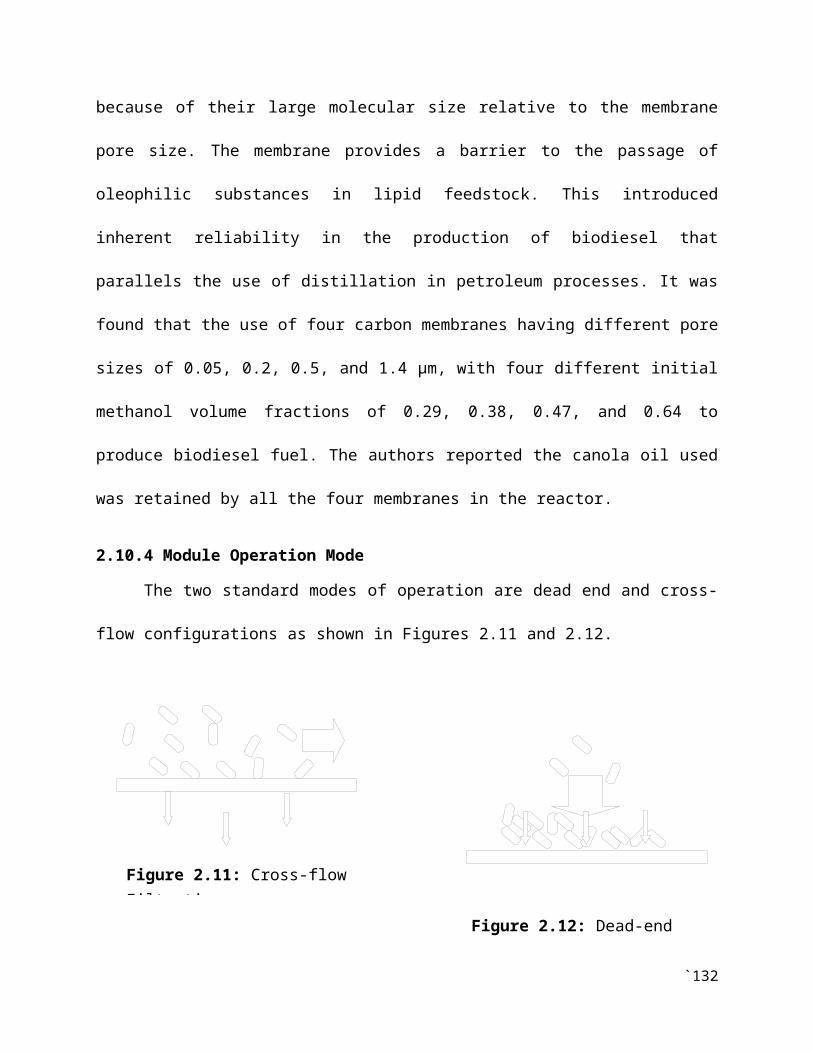
because of their large molecular size relative to the membrane
pore size. The membrane provides a barrier to the passage of
oleophilic substances in lipid feedstock. This introduced
inherent reliability in the production of biodiesel that
parallels the use of distillation in petroleum processes. It was
found that the use of four carbon membranes having different pore
sizes of 0.05, 0.2, 0.5, and 1.4 µm, with four different initial
methanol volume fractions of 0.29, 0.38, 0.47, and 0.64 to
produce biodiesel fuel. The authors reported the canola oil used
was retained by all the four membranes in the reactor.
2.10.4 Module Operation Mode
The two standard modes of operation are dead end and cross-
flow configurations as shown in Figures 2.11 and 2.12.
`132
Figure 2.11: Cross-flow Filtration
Figure 2.12: Dead-endFiltration
In a cross flow filtration, the fluids to undergo filtration
process flows parallel to the surface of the membrane and
permeate through the membrane pores because of the difference in
pressure. The cross-flow process decreases the formation of the
filter cake and keeps it at a low level. Most membrane separation
systems used are operated in a cross-flow feed configuration
where the concentrate passes parallel to the membrane surface as
opposed to perpendicular flow used in dead-end filtration. The
application of solute on the membrane surface is decreased and
the subsequent loss of permeate flux due to increased
hydrodynamic resistance at membrane surface is minimized by
cross-flow induced by hydraulic turbulence (Komolikov &
Blaginina, 2002). The cross-flow mode of filtration reduces the
effect of concentration polarization which induces mass transfer
limitations (Tansel et al., 2009).
Cross-flow filtration is a continuous process in which the
feed stream flows parallel (tangential) to the membrane
filtration surface and generates two outgoing streams. A small
portion of feed, called filtrates or permeates, separates out as
purified liquid passing through the membrane pores. The remaining
`133

portion of the feed is called retentate or concentrate. The
separation is driven by the trans-membrane pressure or the
pressure difference across the membrane. The parallel flow of the
feed stream, combined with the boundary layer turbulence created
by the cross-flow velocity, continually sweeps away particles and
other material that would otherwise build up on the membrane
surface (Sondhi et al., 2003).
2.11 Application of Acidified Water on Membrane Separation
Process
The solubility of glycerol in the esters is reduced by
producing crude biodiesel using a molar ratio of 1:7.5 and the
microfiltration temperature of 50°C. The addition of water
presented a much higher permeate flux. Nonetheless, a sharp drop
in the permeate flux occurred to a mean value of 6.9 kg/h m2,
which remained constant until the end of the run. The results
obtained demonstrated the significance of adding water for the
retention of glycerol, thus the glycerol mass content was lower
than 0.02% demonstrating the efficiency of the methodology used
(Gomes et al., 2011). Saleh et al. (2011) reported that after
`134

addition of water, improved membrane performance in the
separation of glycerol and esters was observed. The authors noted
that addition of water in the range of 0.06 to 0.2wt% led to the
retention of glycerol by the formation of an aqueous phase
dispersed in the esters, which was removed by ultrafiltration.
2.12 Membrane Fouling and Cleaning Process
Membrane fouling and cleaning process are key variables in
the membrane filtration process and these variables are discussed
as follows:
2.12.1 Membrane Fouling
One of the key problems in pressure-driven membrane
processes is reduction in permeate flux far below the theoretical
capability of the membrane due to fouling of the membrane
(Abbasia et al., 2012). The fouling of membrane manifests itself
as a decline in permeates flux with time of operation. The
problem of membrane fouling is the sole most significant reason
for the relatively slow membrane technology acceptance in its
early days. Fouling is due to the deposition and accumulation of
`135

submicron particles on the surface of membranes and/or the
crystallization, precipitation of smaller solutes within the
pores of membrane and the formation of a slowly thickening layer
on the surface of the membrane, thereby causing continuous
permeates flux reduction during the first hours of operation
(Basso et al., 2006; Komolikov & Blaginina, 2002). Membrane
structure has an important influence on improving permeate flux.
If the sizes of the solute molecules are smaller than the
membrane pores, these particles/oil droplets may enter the pores
of the membrane causing irreversible fouling. When the size of
the particles/oil droplets present in the feed solution are
larger than the membrane pores, these particles/oil droplets
accumulate over the membrane surface causing the formation of a
cake/gel layer and/or pore sealing (Salahi et al., 2010).
On start-up of a process, a reduction in membrane permeation
rate to 30–10% of the pure water permeation rate after a few
minutes of operation is common for ultrafiltration. Such a quick
decrease may be even more intense for microfiltration. This is
often followed by a more steady decrease throughout processing.
The degree of membrane fouling is dependent on the properties of
`136
the process feed and on the nature of the membrane employed.
Therefore membrane fouling is firstly controlled by careful
choice of membrane type. Secondly, a good choice of module design
that offers appropriate hydrodynamic conditions for the
particular application. Equally, process feed pretreatment is
also essential. When membrane fouling occurred, the permeation
rate can be substantially restored through back-flushing of the
membrane. Nevertheless, this is rarely totally effective, thus
chemical cleaning is eventually required. The process of membrane
cleaning entails disruption of the membrane separation process.
Due to the extensive nature of cleaning required, quite
substantial time losses may result. Therefore, a typical cleaning
method would necessitate: flushing with filtered water at 35–50oC
to displace residual retentate; back-flushing or recirculation
with cleaning agent, probably at higher temperatures; and rinsing
with water to remove sterilizing solution. More recent approaches
to the control of membrane fouling include the use of more
sophisticated hydrodynamic control affected by pulsated feed
flows or non-planar membrane surfaces, and the application of
`137

further perturbations at the membrane surface such as continuous
or pulsated electric fields (Ghasem, 2007).
2.12.2 Membrane Cleaning
During membrane cleaning process, components are removed
physically, chemically or hydraulically. A module is temporarily
out of order, when the cleaning process is performed. As a
result, dead-end management is a discontinuous process. The
length of time that a module performs filtration is called
filtration time and the length of time that a module is cleaned
is called cleaning time. In practise one always tries to apply
the lowest possible cleaning time and make filtration time last
as long as possible. In addition, ceramic membranes are ideal for
in-place chemical cleaning at high temperatures, while using
hydrogen peroxide, chlorine, caustic, steam sterilization and/or
ozone and strong inorganic acids. These membranes can also be
back-pulsed, which is essentially a permeate flow reversal
technique to decrease fouling and to increase filtration
efficiency. Back-pulsing is an in situ technique for the cleaning of
membrane by periodically reversing the permeate flow by applying
`138

pressure to the filtrate side. In this manner, permeate liquid is
forced back through the membrane to the feed side. This permeate
flow reversal dislodges deposited foulants, which are then
carried out of the membrane module by the tangential flow of
retentate, or which may re-deposit on the membrane surface later
on (Sondhi et al., 2003). The cleaning process is more efficient
when using transmembrane pressure of 0.45 bar. It was suggested
that an efficient way to clean and recover permeate flux of a
ceramic membrane that is submitted to crude soybean oil
ultrafiltration, is by using only hexane. In this way it can help
to the understanding of the behavior of the cleaning process of
deguming of crude oil using ceramic membranes (Basso et al.,
2006).
2.13 Membrane Stability
The remarkable physical and chemical stability of ceramic
membranes permits them to provide reproducible performance over
long service lifetime, which is well established in many
industrial installations. It was demonstrated that the capability
of ceramic membranes to increase yields, recover valuable
products and concentrate process streams, makes them a preferred`139

method of filtration and cost-effective (Sondhi et al., 2003;
Komolikov & Blaginina, 2002).
2.14 Biodiesel Purity via Membrane Refining
The use of membranes to refine crude biodiesel product has
been remarkable, producing biodiesel purity of 99% (He et al.,
2006). This is so because blockage of unreacted triglycerides
during membrane biodiesel production enabled achievement of low
impurity biodiesel (Cao, 2008) as shown in Figure 2.13. Moreover,
Cao et al. (2008a) stated that the glycerol content of biodiesel
produced using membrane reactor is significantly lower than that
produced through a traditional batch reaction. Also, membrane
extraction technique was found to provide about 90% purity of
biodiesel (Leung et al., 2010). Further Cao (2008) reported the
biodiesel produced was of excellent purity without any
confirmation of the presence of particulate matter.
`140

Figure 2.13: Cross flow filtration configuration (Lu et
al., 2007)
`141
= Triglyceride = Biodiesel mixture