Frameless stereotactic ultrasonography: Method and applications
12
Pergamon Computerized Medical Imaging and Graphics, Vol.18, No.4, pp. 235-246, 1994 Copyright 0 1994 Elsevier Science Ltd Printed in the USA. All rights reserved 0895-61 I l/94 $6.00 + .OO 0895_6111(94)E0007-X FRAMELESS STEREOTACTIC ULTRASONOGRAPHY: METHOD AND APPLICATIONS Jason W. Trobaugh *?, William D. Richard*, Kurt R. Smith*, and Richard D. Bucholz§ *Department of Electrical Engineering, Washington University in St. Louis, One Brookings Drive, Campus Box 1127, St. Louis, MO 63 130, USA, ‘Stealth Technologies, Inc. Marine, IL 6206 l-0427, USA, and “Division of Neurosurgery, St. Louis University Medical Center, St. Louis, MO 63 110, USA (Received 2 September 1993) Abstract-In stereotactic neurosurgery, computed tomography ((3) and magnetic resonance (MR) images are registered in a coordinate system defined with respect to the skull. By intraoperatively tracking the coordinate position of a surgical instrument, various displays can be formed which show the position of the instrument in the MR and/or CT images. However, the accuracy of this display varies because intracranial structures may shift or warp from their position prior to surgery. Ultrasonic imaging systems provide real-time images of the brain, but structures in these images are difficult to interpret because the images are based on ultrasonic echoes. A method has been developed for the real-time registration of these images. With this registration, software continuously updates a corresponding image constructed from the s&t of MR and/or CT images used for guidance. By developing this second view of the structures in the ultrasound image, the surgeon can easily interpret the ultrasound image, and it becomes possiblle to determine the extent of the intra-operative structure shift between the two images. Key Words: Stereotactic neurosurgery,Computed tomography, Magneticresonance, Image registration, Structure shift, Stereotactic ultrasonography, Direction cosines, Gram-schmidt orthogonalization INTRODUCTION Various diagnostic imaging modalities have extensively aided the neurosurgeon in areas ranging from pre-sur- gical planning to intra-operative guidance (l-4). Com- puted Tomography (CT) and Magnetic Resonance (MR) images offer tremendous detail and differentia- tion between intracranial structures (3). These images are often used in planning a surgical procedure and are used in stereotactic neurosurgery as a guide for the surgeon. Use of these images as a guide is limited in that the images are formed prior to surgery and do not reflect changes in the structure position or shape that occur during surgery. Ultrasonography is the only real- time, intra-operative imaging modality currently available (4). It has been successfully used in the guid- ance of biopsies and othler procedures (4), but it has been disregarded by some neurosurgeons due to noisy, difficult-to-read images and the inability to differentiate some types of tumors from the surrounding tissue. In stereotactic neurosurgery, the CT/MR images are registered in “surgical space,” a coordinate system defined with respect to the skull. Special surgical in- struments have been de,signed such that the surgical space position of the instrument can be determined +To whom correspondence should be addressed. 235 throughout the course of surgery (2, 5). By displaying images corresponding to that position, the surgeon is given a “guided tour” of the brain as the surgical pro- cedure is performed (6). The system of Bucholz (5) was designed to localize the surgical space position of a modified surgical forceps. Using optical cameras to sense the locations of infrared LEDs (7), the position of the forceps tip is found relative to a simple base frame that attaches to the skull of the patient. The CT/MR images are formed and registered in surgical space prior to surgery. During surgery, struc- tures shift, and the accuracy of the registration is there- fore degraded. Currently, no method exists whereby one can correct the resulting error. Ultrasound provides a real-time image, and if the surgical space position of that image can be determined, a corresponding image can be constructed from the registered CT/MR images. Shift can be measured based on the difference in struc- ture positions between the constructed pre-surgical (CT/MR) image and the intra-operative ultrasound image. In addition, interpretation of the ultrasound image becomes easier because structures in the image can be interpreted based on the corresponding struc- tures in the CT/MR image. This paper describes the design, development, and use of a method for the real- time localization (i.e., determination of surgical space position, of ultrasound images).
-
Upload
independent -
Category
Documents
-
view
0 -
download
0
Transcript of Frameless stereotactic ultrasonography: Method and applications

Pergamon
Computerized Medical Imaging and Graphics, Vol. 18, No. 4, pp. 235-246, 1994 Copyright 0 1994 Elsevier Science Ltd Printed in the USA. All rights reserved
0895-61 I l/94 $6.00 + .OO
0895_6111(94)E0007-X
FRAMELESS STEREOTACTIC ULTRASONOGRAPHY: METHOD AND APPLICATIONS
Jason W. Trobaugh *?, William D. Richard*, Kurt R. Smith*, and Richard D. Bucholz§
*Department of Electrical Engineering, Washington University in St. Louis, One Brookings Drive, Campus Box 1127, St. Louis, MO 63 130, USA, ‘Stealth Technologies, Inc. Marine, IL 6206 l-0427, USA, and
“Division of Neurosurgery, St. Louis University Medical Center, St. Louis, MO 63 110, USA
(Received 2 September 1993)
Abstract-In stereotactic neurosurgery, computed tomography ((3) and magnetic resonance (MR) images are registered in a coordinate system defined with respect to the skull. By intraoperatively tracking the coordinate position of a surgical instrument, various displays can be formed which show the position of the instrument in the MR and/or CT images. However, the accuracy of this display varies because intracranial structures may shift or warp from their position prior to surgery. Ultrasonic imaging systems provide real-time images of the brain, but structures in these images are difficult to interpret because the images are based on ultrasonic echoes. A method has been developed for the real-time registration of these images. With this registration, software continuously updates a corresponding image constructed from the s&t of MR and/or CT images used for guidance. By developing this second view of the structures in the ultrasound image, the surgeon can easily interpret the ultrasound image, and it becomes possiblle to determine the extent of the intra-operative structure shift between the two images.
Key Words: Stereotactic neurosurgery, Computed tomography, Magnetic resonance, Image registration, Structure shift, Stereotactic ultrasonography, Direction cosines, Gram-schmidt orthogonalization
INTRODUCTION
Various diagnostic imaging modalities have extensively aided the neurosurgeon in areas ranging from pre-sur- gical planning to intra-operative guidance (l-4). Com- puted Tomography (CT) and Magnetic Resonance (MR) images offer tremendous detail and differentia- tion between intracranial structures (3). These images are often used in planning a surgical procedure and are used in stereotactic neurosurgery as a guide for the surgeon. Use of these images as a guide is limited in that the images are formed prior to surgery and do not reflect changes in the structure position or shape that occur during surgery. Ultrasonography is the only real- time, intra-operative imaging modality currently available (4). It has been successfully used in the guid- ance of biopsies and othler procedures (4), but it has been disregarded by some neurosurgeons due to noisy, difficult-to-read images and the inability to differentiate some types of tumors from the surrounding tissue.
In stereotactic neurosurgery, the CT/MR images are registered in “surgical space,” a coordinate system defined with respect to the skull. Special surgical in- struments have been de,signed such that the surgical space position of the instrument can be determined
+ To whom correspondence should be addressed.
235
throughout the course of surgery (2, 5). By displaying images corresponding to that position, the surgeon is given a “guided tour” of the brain as the surgical pro- cedure is performed (6). The system of Bucholz (5) was designed to localize the surgical space position of a modified surgical forceps. Using optical cameras to sense the locations of infrared LEDs (7), the position of the forceps tip is found relative to a simple base frame that attaches to the skull of the patient.
The CT/MR images are formed and registered in surgical space prior to surgery. During surgery, struc- tures shift, and the accuracy of the registration is there- fore degraded. Currently, no method exists whereby one can correct the resulting error. Ultrasound provides a real-time image, and if the surgical space position of that image can be determined, a corresponding image can be constructed from the registered CT/MR images. Shift can be measured based on the difference in struc- ture positions between the constructed pre-surgical (CT/MR) image and the intra-operative ultrasound image. In addition, interpretation of the ultrasound image becomes easier because structures in the image can be interpreted based on the corresponding struc- tures in the CT/MR image. This paper describes the design, development, and use of a method for the real- time localization (i.e., determination of surgical space position, of ultrasound images).

236 Computerized Medical Imaging and Graphics July-August/l 994, Volume 18, Number 4
Sector-scanning ultrasound probes have histori- cally been used for neurosurgical purposes because of their small size in relation to a linear array (4). The position of such an ultrasound probe was monitored by attaching LEDs to the probe in a rigid fashion. A commercial position-sensing system was used to mon- itor the surgical space positions of the LEDs (7). Cal- ibration was necessary for each probe due to the me- chanical tolerances inherent in the manufacture of the probes. Calibration was accomplished by determining the image position for a fixed probe position. The po- sitions of real-time images were then obtained by find- ing the three-dimensional (3D) movement of the probe and image from the calibration position. Optimized solutions for calibration and movement resulted in lo- calization accuracy at a limit set by the error inherent in the LED position-sensing system. Software was de- veloped to localize the image in real-time and to con- struct corresponding oblique CT/MR images. The ef- fectiveness and accuracy of the technique was first demonstrated on various phantoms. The equipment was then modified to allow its use in the operating room, and the system was used successfully in several stereotactic neurosurgery cases.
METHOD OF LOCALIZATION
Calibration Localization of an ultrasound image involves de-
termining a direct correlation between each pixel in the image and its position in surgical space. This can be specified mathematically by the following equation:
where the left hand side represents the surgical space position of image pixel (x, y). The unknown vectors are the surgical space position for the lower-left comer of the image [pixel (0, 0)], the surgical space vector distance between adjacent horizontal pixels (horiz), and the surgical space vector distance between adja- cent vertical pixels (vet-t). This is shown graphically in Fig. 1.
Equation (1) can also be represented as follows:
[Gl /-%,0, xs%~,Z XS&<J r 11
The 3 X 3 matrix in this equation contains all of the unknown quantities. This matrix can be deter- mined by any system of equations approach if the sur-
,Y (%p* Yup> E
(x,Y,zkJ,lJ /“”
@
%,Y)
@rt~:‘lrzrt)
*X
Fig. 1. A 2D image in a 3D coordinate system.
gical space positions are known for at least three pixels in the ultrasound image. Phantoms have been created for calibration consisting of three objects that can be imaged simultaneously. The surgical space position of each object must be found, and an image pixel location corresponding to that position on each object must be determined. With these values, the matrix in Eq. (2) can be solved for.
The final calibration phantom consisted of 0.4 mm nylon wire connected through a plastic container to make three wire “crosses.” This phantom is shown in Fig. 2. When imaging a cross, the image shows two wires unless the center of the cross is directly in the plane of the image. This characteristic makes it easy to image the cross center and feasible to image all three objects simultaneously. However, because there will be error inherent in each of the required measurements, the use of optimization techniques can increase the accuracy of the localization. The application of these techniques to calibration are de- tailed in a later section.
Movement For any position of the probe, image localization
is obtained by finding the solution to Eq. (1). The po- sition of the image is fixed in relation to the probe. Thus, the image and probe can be viewed as a single object, and movement of the probe requires the same movement of the image. A mathematical relation that defines the movement of the probe also defines the movement of the image. After solving Eq. (1) for the calibration position, an image at any new position can

Frameless stereotactic ultrasonography ??J. W. TROBAUGH et al. 231
Fig. 2. Wire “Cross” Calibration Phantom.
be localized if there is a method for defining the move- ment between the two positions.
Object movement can be uniquely described in a coordinate system by an equation that allows both translation and rotation. Ftotation of the object about each of the three coordinate axes is specified by a 3 X 3 matrix. Then, a vector for translation is added to the coordinates for the rotated object. This transformation can be mathematically defined by the following general relation:
The new position of a point fixed in relation to the object can be calculated given the old position. Intu- itively, the matrix A allows for rotation about the axes, and the vector tran allows for translation between the two positions, However, this relation is not constrained to consist only of translation and rotation; nonuniform scaling with respect to each axis can be included in this simple relation. Thus, a solution to Eq. (3) using a system of equations approach would compensate for error inherent in the input points by incorporating scaling. Thus, it is necessary to find a relation that is constrained to simple movement in 3D.
Rotation about the origin is uniquely described by
(4)
1 4x 4,” +z 1 where the elements are the direction cosines for each axis (8). Each direction cosine is the cosine of the angle between the new axis and the old axis (i.e., X, is the cosine of the angle between the old x axis and the new
y axis). Equivalently, each row of Eq. (4) is the unit vector that defines each new axis in the old reference frame. Therefore, rotation from the new system to the reference system is obtained by multiplication of the new point by (4). Rotation from the reference system to the new system is defined by the transpose of the direction cosines matrix (8).
This concept can be extended to rotation between two systems defined in the same reference system. The two-system rotation can be viewed as rotation from the initial system to the reference system and then to the new system. Thus, the overall rotation matrix is the product of the transpose of the second system ma- trix and the first system matrix.
For the probe, movement from one position to a new position can be defined by constructing an equiv- alent coordinate system in each of the two positions. This “probe coordinate system” remains fixed with re- spect to the probe. It can be constructed based on points fixed in the probe coordinate system (i.e., LEDs mounted rigidly to the probe). At least three fixed points are required, and the points must form a plane (i.e., they cannot lie on the same line). One of the three points can be chosen as the origin of the system. The x-axis can be defined as the vector from the defined origin to a second point. By defining the vector from the origin to the third point to be in the upper half of the x-y plane, the coordinate system is uniquely de- fined. To determine the direction cosine matrices, the unit vectors for each axis need to be determined. The z-axis is the cross product of the x-axis vector and the vector in the x-y plane. The y-axis is then the cross product of the z and x axes. This method for con- struction of equivalent coordinate systems is shown in Fig. 3.
With this approach, the transformation can consist of only translation and rotation, and it is mathemati- cally defined as follows:
where 0 designates the probe coordinate system origin for that position.
In constructing the probe coordinate system, the simplest choice for the three required points is to mea- sure the positions for three points fixed with respect to the probe. In implementation, a method of sensing surgical space position for each point is required. Ac-
238 Computerized Medical Imaging and Graphics July-August/ 1994, Volume 18, Number 4
Fig. 3. Construction of equi\ ralent coordinate systems.
curacy of the method is crucial to obtaining useful im- age localization. Currently, infrared LEDs attached to the probe are tracked by an optical position-sensing system (7). Three linear CCD camera arrays detect the emitted light and determine the 3D position of each LED. Surgical space is defined by a metal ring that holds three LEDs and attaches to a frame affixed to the skull of the patient. The positions of these LEDs are determined relative to the cameras, and software in the optical system determines the position of surgical space. Positions for any additional LEDs are then re- ported in surgical space coordinates. An alternative method for position-sensing is a mechanical arm such as the one described in eq. (2).
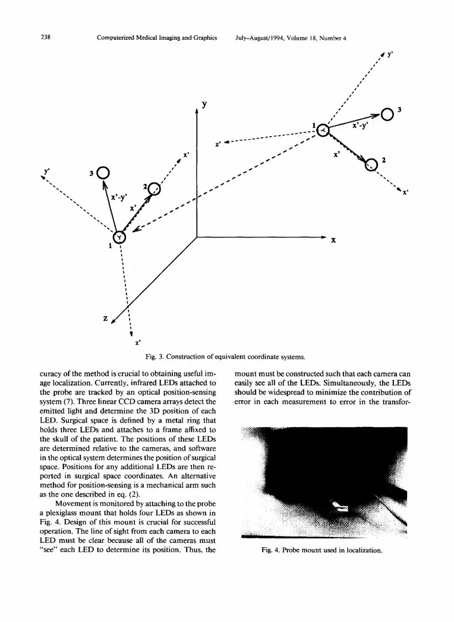
Movement is monitored by attaching to the probe a plexiglass mount that holds four LEDs as shown in Fig. 4. Design of this mount is crucial for successful operation. The line of sight from each camera to each LED must be clear because all of the cameras must “see” each LED to determine its position. Thus, the
t’ #’
1 -( I' 0
3
x'_y' __ ___--- )
____-- ___--- . . . . . .'
%
X’ /
.)) 2
*\ 0& *\
,@ ‘. \
mount must be constructed such that each camera can easily see all of the LEDs. Simultaneously, the LEDs should be widespread to minimize the contribution of error in each measurement to error in the transfor-
Fig. 4. Probe mount used in localization.

Frameless stereotactic ultrasonography ??J. W. TROBAUGH et al. 239
mation solution. Also, the lmount must be small enough to be easily used and maneuvered by the physician during surgery.
In order to be used in the operating room, the probe and LED mount must be sterilized. By itself, the ultrasound probe used here cannot be sterilized but is covered with a sterile drape. LEDs cannot be seen through the drape, and the mount must remain fixed with respect to the probe after calibration. Thus, the mount was designed so th(at it could be removed and then attached in exactly the same position. An inner ring is affixed directly to the probe, and the LED mount is attached to the fixed ring over a sterilized drape. The probe can then be used in the operating room, and calibration must be performed only one time for a given probe. In Fig. 4, the inner ring is already attached to the probe, and the mount is being attached. In use, the drape fits between the ring and the mount.
Real-time localization After calibration has been performed for a given
probe, images can be localized in real-time. The cali- bration image has been defined by the matrix in eq. (2) for the calibration position. Movement from the calibration position to any new position is defined as in eq. (5). The matrix in eq. (2) for the real-time image can then be easily determined. The first vector in eq. (2), the surgical space position for pixel (0, 0) in the image, is found by transforming the first vector in eq. (2) from the calibration image with the defined move- ment. Because the other two vectors in the matrix are directions, they have only been rotated between posi- tions, and the calibration vectors need only to be ro- tated with the two direction cosines matrices from eq. (5). These calculations can be done in real-time, allow- ing the position of the read-time ultrasound image to be continuously monitoreld.
For use in neurosurgical imaging, a correction must made in the localization. In calibration, the wires are submerged in water to allow imaging. The speed of ultrasound is 1498 m/s in distilled water at room temperature, while the average speed of ultrasound in the brain is 1560 m/s. Thus, any spatial measurements made with the ultrasound system must be compensated to account for this difference if the system is not prop- erly adjusted. In one PS, the wave travels 1.560 mm in the brain. If not adjusted, the system reports the dis- tance travelled to be 1.498 mm. Thus, every distance measured by the system should be scaled by a correc- tion factor of 1.560/1.498. If the correction factor is not included, spatial measnrements in the image will contain errors of approximately 4% of the distance from probe crystal to the position measured.
OPTIMIZATION
Calibration The accuracy of the system is critical if position
measurements are to be used to assess shift. There are essentially two main sources of error in real-time image localization. First, the error inherent in the position- sensing equipment was approximately 1.5 mm, on av- erage. These measurements of position are used in the movement solution and in determining position for calibration objects. Second, in calibration, it is difficult to align the scanning plane of the ultrasound probe exactly with the plane formed by the three calibration objects, and the measure of the image pixel location for each object is imperfect. Reduction of the error in position-sensing is dependent only on advances in that technology, and imaging error can be limited with ex- perience in using the ultrasound system. Given that some error will inevitably be present, a technique was developed to optimally localize an image by utilizing knowledge about the system and by incorporating re- dundancy in the required measurements.
Localization for the calibration image can be ac- quired directly by solving the system of equations that results when three corresponding points in surgical space and in the ultrasound image are known. Yet, this solution will include error because of the error inherent in the image plane, the measurement of pixel locations for each object, and the error in measured surgical space position for each object. Two optimization methods have been investigated to find the best solution given the available information.
Given three points, one can build a constraining equation that must always be true based on the fact that the 3D vectors describing horizontal and vertical directions for the image are perpendicular, that is,
( Xhoriz, Yhorh zhoriz) -L (xvero Yvert~ ZverJ. (f-5)
An optimal solution can be acquired by forcing this constraint to be true (i.e., setting the dot product equal to zero and solving for the least-squared error relation given the three points). This requires an iterative so- lution. An initial guess is made at the solution, and this guess is then adjusted iteratively based on the value of the constraining equation. The process is continued until the constraint is met within a certain range. This approach was not implemented because the second method is more flexible, easier to implement, and al- lows the use of redundant information.
The second approach is based on incorporating redundancy in the measurements. If surgical space po- sitions can be measured for more than three points in the image, a least-squared-error solution can be found using Gram-Schmidt Orthogonalization (9). Extending

240 Computerized Medical Imaging and Graphics
the localization equation so that it contains y1 points results in the following:
or
A = x*B. (8)
This relation is orthogonalized by multiplying both sides by BT,
and
A*B= = x*B*B=, (9)
x = A* BT*(B* B=)-‘. (10)
Assuming that these matrices are of full rank (i.e., no equation can be formed from any linear combi- nation of the other equations), the desired matrix can be found explicitly as in eq. (10). It can be shown that this is the least-squared-error solution given the y1 points found in the image (9).
Obtaining one image with enough points to make this method feasible, however, is difficult as it would require construction of a phantom with n coplanar ob- jects that could be imaged simultaneously. Because ul- trasound operates on the reception of reflected sound waves, it becomes extremely difficult to “see” one ob- ject separated from the probe by another object. Also, the construction of a phantom with several coplanar objects would require significant mechanical precision. However, given the ability to transform images between probe positions, points can be taken at several locations and then transformed to one position. This results in essentially one image with several points whose loca- tions are known. This method offers distinct advan- tages: it allows use of the orthogonalization for an un- limited number of points, and it requires imaging only one object at a time allowing increased accuracy with less difficulty. The primary limitation to this method is the fact that the accuracy of the transformed points depends largely on the accuracy of the solution to the transformation.
Movement Use of eq. (5) in determining the movement be-
tween positions eliminates the inclusion of scaling that
July-August/ 1994, Volume 18, Number 4
would exist in a direct solution, but some error will still be present since the points used to construct the coordinate system will always have some degree of in- accuracy. It is, thus, beneficial to minimize the prop- agation of this error through the system. The choice of the three points used for construction of the probe co- ordinate system will affect the accuracy of the solution.
Measurements of the positions of the LEDs at- tached to the probe give information about the position of the probe and image. These measurements must be used to develop the probe coordinate system. Again, the simplest choice would be the use of three LED measurements as the three required points for the con- structed coordinate system. However, given that each measurement has an error of approximately 1.5 mm, it is desirable to find a choice for the points that min- imizes the error in the solution. Error inherent in a point chosen as the origin will be propagated directly through the solution since the translation of the probe is determined from this point. The points chosen to define the axes of the coordinate system determine the rotation of the system. Thus, a better choice for the construction points will minimize the error from any one LED measurement in the choice of the origin. This can be accomplished by choosing the center of all LED measurements as the coordinate system origin. Note that this point will remain fixed with respect to the probe but contains an average of the error inherent in each of the LEDs. The second and third points form vectors with the origin that are used to determine the axes of the coordinate system. It is best to use points that form vectors separated by 90”. Thus, any error in the measurement will contribute less rotational error than if a smaller or larger angle was formed. Error can also be decreased by choosing the second and third construction points as an average of some LED mea- surements, again to average the error contributed by any one measurement.
The orthogonalization technique could be used to obtain an optimal transformation solution. Again, as each measurement is inherently approximate to some degree, it is desirable to minimize the weight of any one measurement in arriving at a solution. A coordi- nate system origin can be obtained using an average of all measurements, the center of the LEDs. This can be extended to any number of points, making it useful when applying an orthogonalization procedure to the solution. Once the origins are obtained, the rotation matrix must be acquired. With more than three points, this can be obtained using the procedure described above to find the least-squared-error solution. Though this method does not maintain the purely rotational quality as desired, the resultant matrix could be ad-

Frameless stereotactic ultrasonography ??J. W. TROBAUGH et al. 241
Table 1. T:ypes of error
Error Amount (mm)
Measured (Any Image) .3-2.8 Measured (Calibration Images) .l-.75 Movement Solution .3 Position Sensing 1.5 Actual Error 1.5
justed to form the direction cosines matrix which is “closest” to the resultant matrix.
In the current system, four LEDs are mounted on the probe. From measurernents of their locations, the rotation matrix is calculated using each of the four possible combinations of the three points. The four matrices are averaged to obtain the best possible ro- tation matrix. The accuracy of the system based on this method has proven sufficient in that it has main- tained the level of accuracy inherent in the point mea- surements used to define ihe transformation (i.e., ap- proximately 1.5 mm).
The accuracy in localization has been improved significantly by incorporating redundancy into the sys- tem and by utilizing the optimization techniques de- scribed above. In addition, these techniques are such that the amount of redundancy can be increased with minimal changes in the software used in the imple- mentation.
RESULTS
Table 1 lists the types of errors involved in the system and the magnitude: of those errors for a given probe. The tests were perl’ormed using the wire cali- bration phantom and the optical position-sensing sys- tem. Eight images were talcen of one wire cross at dif- ferent positions in the image. The position of this cross was acquired using the optical position-sensing system. The eight images were then transformed to one position to form a composite image with eight crosses. To assure that the solution for movement between positions was accurate, the positions of the LEDs were transformed and compared to those for the composite position. Seven of the eight transformations were within 0.3 mm for each LED point. The orthogonalization procedure was then used with the va.lues for those seven points to localize the composite irnage. Using this calibration, localization accuracy was tested for several images of a wire cross at different positions. Surgical space lo- cation for the cross was ‘calculated using the trans- formed image position, and measured using the digi- tizer system. The difference in these locations was the measured error in localization. When tested for the calibration images, this error ranged from . 1 to .75 mm.
The error ranged from .3 to 2.8 mm with an average of 1.5 mm for images not used in the calibration. This error can be attributed partly to the inaccuracy inherent in positions sensed by the digitizer and by user difficulty in obtaining an accurate measure of position to the nearest mm for a wire cross. It could be decreased through the use of a less user-sensitive position-sensing mechanism in both the calibration and the measure- ment procedure. Assuming that the position-sensing system contributes 1.5 mm of error, error in the image localization is estimated to be +1.5 mm.
The system has been tested on several phantoms constructed so that the contents could be imaged with ultrasound and CT or MR. Work with various elements suspended in gelatin, a commonly used ultrasound phantom, showed preliminary success, but limited dif- ferences in densities of the gelatin and elements proved to yield poor quality CT and MR images. Figures 5 and 6 show an ultrasound image of the phantom and the corresponding CT construction. In this phantom, the elements were olives with pimentoes.
Experience with other elements in gelatin showed that none would give the desired detail in CT/MR im- ages, so a canine brain was acquired from a research animal. One half of the brain was suspended in gelatin, and an MR scan of the phantom was used to test and demonstrate the effectiveness of the system. Figures 7 and 8 show an ultrasound image of the brain and an image constructed from an MR volume to match the
Fig. 5. Ultrasound image of olive phantom.

Computerized Medical Imaging and Graphics July-August/ 1994, Volume 18, Number 4
Fig. 6. Constructed CT image to match ultrasound image.
ultrasound image. In the ultrasound image, a sharp horizontal echo near the top represents the gelatin/ water interface; the representation of the brain in the image is limited due to attenuation of the ultrasound. However, the utility of image comparison is apparent in that the source of the echoes in the ultrasound image can be determined by looking at the corresponding MR image. In addition, these images demonstrate the shift that can occur after acquisition of a CT/MR set. Afier the MR volume was constructed, the gelatin mold cracked and the brain shifted. A measurement of brain position in the horizontal direction for both images shows this shift.
USES AND APPLICATIONS
The original goal for the localization of ultrasound images was its possible role in stereotactic neurosurgery. Ultrasound has been used extensively in neurosurgery, but its full potential has never been realized due to difficulties in the interpretation of the images, especially in comparison with CT or MR. Structures are difficult to discern since the image is based on received echoes rather than characteristics of the tissue as in CT or M& However, the use of a real-time imaging system in the operating room is invaluable. No other modality allows constant monitoring of the surgery as it occurs (4). By localizing the ultrasound image with reference to the same coordinate system as a volume of CT or MR data, an image can be constructed from this vol- ume to complement the ultrasound image and aid in its interpretation.
The required position-sensing is accomplished by optically tracking infra-red LEDs. This method works well but is limited because the LEDs must be seen by the optical equipment for a position to be measured.
Fig. 7. Ultrasound image of canine brain.
The stereotactic ultrasound methods described here are independent of the method used to determine position, however. Another possibility for position-sensing is the use of a mechanical arm constructed so that its position can be determined (2). This method is not limited by the “line-of-sight” problems in the optical method, al- though this method has its own disadvantages.
Currently, 3D rendering software can be used to show the volume of CT/MR data with the plane of the ultrasound image exposed. This gives a view of the structures in the image along with a representation of the surrounding 3D structures. A cross-section of the volume in the plane of the image can also be displayed in the same orientation as the ultrasound image. A fan shape is overlaid to show exactly where the corre- sponding ultrasound image would be. In addition, a CT/MR image is constructed to correspond to the ul-
Fig. 8. Constructed MR image to match ultrasound image.

Frameless stereotactic ultrasonography ??J. W. TROBAUGH et al. 243
Fig. 9. Ultrasound image during neurosurgery Case 1.
trasound image; the calculated position for each pixel in the ultrasound image is used to determine a CT/ MR pixel value based on the same position in the CT/ MR volume. Brightnesses are interpolated trilinearly from the eight nearest voxels in the volume. The time required to render is about 5 s with a volume consisting of sixty 256 X 256 images. A second version of the software displays only the (constructed CT/MR image with emphasis on the speed of rendering. Approxi- mately three images per second can be displayed, al- though this time is not yet realizable during surgery due to delays in the interface between the optical po- sition-sensing system and the Silicon GraphicsTM workstation. In final form, this software will provide a continuous real-time update of the constructed image giving the surgeon a nearly “live” CT/MR image.
Figures 9 and 10 show an ultrasound image and a matching MR image from a stereotactic neurosurgery case. In these images, the tumor is apparent near the top of the images. Additionally, a large space exists at the bottom of the ultrasound image where no echoes were received. The corresponding MR image shows a section of uniformly dense tissue at this same position. Thus, one would expect the absence of echoes seen in the ultrasound image. Also, what appears to be noise in the left side of the ultraisound image is most likely echoes resulting from highly reflective interfaces in the tumor seen in the MR imaige.
Figures 1 l- 16 are matching images for another case and further show the utility of stereotactic ultra-
Fig. 10. Constructed MR image from neurosurgery Case 1.
sound in neurosurgery. In the first set, Figs. 11 and 12, the tumor can be seen in the center of each image, approximately 45 mm in from the skull. Tumors seated this deeply are especially susceptible to shift and reg- istration degradation. The second set, Figs. 13 and 14, show the extent to which structures from the ultrasound image can be interpreted from corresponding structures in the MR image. In Fig. 14, the side of the tumor is seen though it is not apparent in the ultrasound image. This may be due to one or more of several possible
Fig. 11. Ultrasound image 1 during neurosurgery Case 2.

244 Computerized Medical Imaging and Graphics July-August/ 1994, Volume 18, Number 4
Fig. 12. Constructed MR image 1 from neurosurgery Case 2.
sources of error: calibration and localization error, structure shift, and/or error in registration of MR im- ages including error due to MR distortions and error in mathematical registration. The final set, Figs. 15 and 16, also show several intracranial structures and the advantage of having the corresponding MR image to aid in interpretation of the ultrasound image.
Research is underway to develop methods for as- sessing brain shift that occurs after CT/MR images are
Fig. 14. Constructed MR image 2 from Case 2.
formed. Upon opening the skull for surgery, the tissue moves in relation to its preoperative position. By com- paring the ultrasound image and corresponding CT/ MR image, an assessment of the shift in structures can be made. Ideally, this information would be used along with template deformation techniques (10) to realign the CT/MR image to represent the current shape and position of the brain during surgery. Furthermore, by taking several images at different locations, a volume
Fig. 13. Ultrasound image 2 during neurosurgery Case 2. Fig. 15. Ultrasound image 3 during neurosurgery Case 2.

Frameless stereotactic ultrasonography ??J. W. TROBAUGH et al. 245
of ultrasound data could be constructed using inter-
Fig. 16. Constructed MIX image 3 from Case 2.
polation techniques. This volume could be accessed so that template deformation could be used to deform all of the original slices from the CT/MR volume.
Other surgical techniques may also benefit from stereotactic ultrasound. As long as the desired area can be imaged with ultrasound and CT or MR, a 3D vol- ume of CT or MR slices can be registered to allow construction of corresponding CT/MR images. Es- pecially interesting is the possibility for use with recent advances in cryogenic liver surgery (11).
Possibilities also exist for using the localization technique to construct 3D ultrasound images. Tech- niques are being developed for construction of a 3D volume based on the brig,htnesses at a number of known locations within the volume. By assigning a po- sition in space to the volume, the pixels in localized images can be used to estima.te the true brightness value that should be associated wllth each voxel. This would have a distinct advantage lover 3D ultrasound tech- niques requiring strict position movement in that a basic ultrasound system could be used with the addition of position-sensing equipment. This volume could be displayed as an image using 3D rendering software, or could be used for measurements of position for 3D structures.
CONCLUSIONS
Stereotactic neurosurgery is not used by all neu- rosurgeons because of the limitations inherent in cur- rent techniques. Problems with accuracy in the regis- tration of CT/MR images result from movement of tissue during surgery. Localj.zed ultrasound allows the
surgeon to constantly monitor the intra-operative po- sition of structures relative to their pre-operative po- sitions in addition to using ultrasound itself as a guide. A simple assessment of the shift in these structures can be made qualitatively, and a venue is created through which automatic segmentation and correlation of structures in the corresponding images could provide a continuous update of the original volume contents and thereby reduce the degenerate accuracy caused by tissue movement.
SUMMARY
In stereotactic neurosurgery, the position of a sur- gical instrument is tracked in a coordinate system de- fined with respect to the skull. By registering CT or MR images in the defined coordinate system, position can be visually displayed. However, guidance based on CT/MR images registered prior to surgery suffers be- cause brain structures shift with respect to the skull as surgery progresses. An alternative method for moni- toring progress with medical images involves the use of real-time ultrasonography. The instrument can be seen in the image, and its position with respect to sur- rounding structures can be monitored. Structures in the ultrasound image are difficult to interpret, though, because the image is based on echoes reflected from various tissues. These two problems with current neu- rosurgical techniques motivated the development of stereotactic ultrasound.
By monitoring positions of infra-red LEDs at- tached to an ultrasound probe, the position of ultra- sound images is determined in the standard coordinate system. By constructing a corresponding CT/MR im- age from the same position, one sees a second view of the structures in the ultrasound image, and it becomes possible to measure shift of structures from preopera- tive to intra-operative position.
Localization is accomplished in two steps. The probe is first “calibrated” by determining the image position for a given probe position. Given this cali- brated probe, if movement of the probe can be defined, the movement of the image is known because it re- mains fixed with respect to the probe. Optimal cali- bration is found using the Gram-Schmidt Orthogon- alization Procedure to find a relation for image position. A method for determining movement of the probe is based on the direction cosines and simple 3D translation. Thus, for any position of the ultrasound probe during imaging, the position of the image can be determined.
The stereotactic ultrasound system was tested on several phantoms and then used in neurosurgical cases. The accuracy was tested to be 1.5 mm, the limit set by

246 Computerized Medical Imaging and Graphics July-August/l994, Volume 18, Number 4
error inherent in the LED-sensing equipment. Images are shown that demonstrate the effectiveness of this method, and further research possibilities are stressed.
Acknowledgments-We would like to extend our appreciation to Linscan Systems, Inc., of Rolla, Missouri for the use of their ultrasonic equipment in this research project, and to Joe Tricamo of the St. Louis University Machine Shop for his assistance in the production of the LED mounts for the ultrasound probe. Jason Trobaugh was funded under a fellowship grant from the Department of Education.
REFERENCES
I. Kandel, E.L. Functional and stereotactic neurosurgery. New York: Prenum Medical Book Publishing Company; 1989.
2. Guthrie, B.L.; Adler, Jr., J.R. Computer-assisted preoperative planning, interactive surgery, and frameless stereotaxy. In: Clin- ical neurosurgery. Baltimore: Williams and Wilkins; 1990: I 12.
3. Kazner, E.; Wend, S.; Grumme, T.; Stochdorph, 0.; Felix, R.; Claussen, C. Computed tomography and magnetic resonance tomography of intracranial tumors. New York: Springer-Vedag; 1989.
4. Rubin, J.M.; Chandler, W.F. Ultrasound in neurosurgery. New York: Raven Press; 1990.
5. Bucholz, R.D. System for indicating the position of a surgical probe within a head on an image of the head. U.S. Patent Pending. Application S.N. 07/600,753.
6. Smith, K.R.; Bucholz, R.D. Computer methods for improved diagnostic image display applied to frameless stereotactic neu- rosurgery. Automedica 14371-382; 1992.
7. Macellari, V. A computer peripheral remote sensing device for 3-dimensional monitoring of human motion. Med. Biol. Eng. Comput. 21:31 l-318; 1983.
8. Beyer, W.H. CRC standard mathematical tables. Boca Raton, Florida: CRC Press, Inc.; 1987.
9. Dorny, N. A vector space approach to models and optimization. USA: John Wiley and Sons, Inc.; 1975.
10. Amit, Y.; Grenander, U.; Piccioni, M. Structural image resto- ration through deformable templates. J. Am. Stat. Assoc. 86: 376-87; June 199 1.
I 1. Scearce, K. Freezing away tumors: Cryomedical sciences launches new product. Washington Technology 7( 10):32; Aug 27, 1992.
About the Author-JASON W. TROBAUGH received his M.S.E.E. in May of 1993 and is currently working on his D.Sc. at Washington University in St. Louis. His research interests include medical imaging computer vision, ultrasonic imaging and image processing.
About the Author-WILLIAM D. RICHARD received his Ph.D. from the University of Missouri-Rolla and joined the faculty at Washington University in St. Louis in 1988. His research interests include ultra- sonic imaging and medical instrumentation.
About the Author-KURT R. SMITH received his D.Sc in Electrical Engineering from Washington University in St. Louis and is currently the President and Director of Product Development at Stealth Tech- nologies, Inc. His research interests include imaging and computer vision algorithms for medicine, custom high-speed implementations of these algorithms, the development of integrated computer work- stations for surgery and radiology, and high-bandwidth communi- cation systems for multimedia in medicine.
About the Author-RICHARD D. BUCHOLZ received his M.D. at Yale University and is currently an Associate Professor of Surgery at St. Louis University Medical Center. His research interests include the application of computer technology in neurosurgical procedures and post-operative patient monitoring, the application of intra-operative ultrasonography to correct distortions in preoperative datasets, skull base surgery with carbon dioxide and YAG lasers, and any and all uses of personal computers.