Formation of Riedel shear fractures in granular materials: Findings from analogue shear experiments...
7
Formation of Riedel shear fractures in granular materials: Findings from analogue shear experiments and theoretical analyses Santanu Misra a, ⁎, Nibir Mandal b , Chandan Chakraborty c a Department of Geological Sciences; Jadavpur University, Kolkata 700032, India b Indian Institute of Science Education and Research, Kolkata 700106, India c Geological Studies Unit, Indian Statistical Institute, Kolkata 700108, India abstract article info Article history: Received 31 August 2008 Received in revised form 11 February 2009 Accepted 18 February 2009 Available online 28 February 2009 Keywords: Brittle failure Coulomb–Navier criterion Shear fractures Rheology Anisotropy We performed simple shear experiments to investigate the development of low- (R 1 ) and high- (R 2 ) angle Riedel shear localization in wet sand–talc mixtures with varying volume proportions. With increasing talc content, the granular medium underwent rheological changes, showing larger homogeneous ductile strains prior to brittle failure. Talc-rich models developed a perceptible penetrative planar fabric of flaky talc grains in response to the ductile strains. The relative growth of R 1 and R 2 also varies consistently with talc content. Both R 1 and R 2 formed equally at angles of ~15° and ~75° to the bulk shear direction, respectively, when the medium was of pure sand. In contrast, a talc-rich (90% by volume) medium produced only R 1 shear fractures. The rheological changes and the presence of a shape fabric in the medium appear to be the potential factors resulting in the variation of R 1 versus R 2 growth in the experiments. We present a theoretical analysis to show possible effects of the penetrative fabric independently, considering mechanical anisotropy in the medium. This analysis takes into account two anisotropic factors, m: ratio of shear and Young's modulii, and n: ratio of Young's modulii along and across the fabric. The shear failure is assumed to follow a Coulomb– Navier criterion. Theoretical calculations show that the Coulomb stress factor (F) for isotropic materials (m= 0.33 and n =1) reaches maximum values on planes oriented at angles of 15° and 75° to the bulk shear plane, leading to shear failure along both R 1 and R 2 . In the case of anisotropic materials (mb 0.33 or n N 1), the stress factor is characterized by a single maximum of F within the range of 0° to 90°, corresponding to planes oriented at a low angle to the bulk shear plane (R 1 ). © 2009 Elsevier B.V. All rights reserved. 1. Introduction Granular materials, such as rocks, soils and ceramics, fail at a critical yield stresses, forming deformation bands or shear fractures arranged in multiple sets with varying geometry and kinematics. The most important varieties of these failure surfaces are known as Riedel shear bands or fractures (Cloos, 1928; Riedel, 1929; Oertel, 1965; Tchalenko, 1970; Wilcox et al., 1973; Rutter et al., 1986; Pollard and Segall, 1987; Evans et al., 1990; Davis et al., 2000; Nova, 2003; Schmocker et al., 2003). Riedel shears generally occur in two orientations: one at an angle of about 15° (R 1 ) and the other at an angle of about 75° (R 2 ) to the bulk shear direction (Logan et al., 1979; Dresen, 1991; Katz et al., 2004). The sense of shear on R 1 is synthetic, whereas that on R 2 is antithetic to the sense of bulk shear. The issue of R 1 versus R 2 shear localizations is important in the study of shear failure, as both experimental and field observations suggest that they do not grow equally in the course of progressive shear deformation. For example, shear failure can take place with the preferential development of a single set of R 1 fractures. Closely spaced R 2 fractures develop later due to secondary stress localization in the bridges between adjacent R 1 surfaces (Davis et al., 2000, Ahlgren, 2001; Schultz and Balasco, 2003; Katz et al., 2004). There are many instances in the field as well as in experiments where shear zones contain only R 1 shear fractures, and R 2 is virtually absent. However, according to the theory of failure mechanics, shear fractures are likely to form equally as two sets, disposed symmetrically with respect to the principal axes of stress in shear zones. Several workers have dealt with this issue and attempted to explain the preferential growth of R 1 (e.g., Muhunthan et al., 2003; Schmocker et al., 2003, Katz et al., 2006). Based on rock deformation experiments, Schmocker et al. (2003) have proposed that intergranular pores develop in larger concentrations along low-angle shear surfaces and thereby promote the growth of R 1 in preference to R 2 . In such a situation, R 2 bands remain dormant, whereas R 1 shear fractures propagate at high rates. On the other hand, Katz et al. (2006) considered materials with a non-linear (power-law) rheology and estimated the growth rate of band porosity as a function of the band orientation. With increasing non- linearity, the growth rate shows a transition from a single peak at 45 o to two symmetrically disposed peaks at 15° and 75° to the shear direction, implying equal development of R 1 and R 2 shear. It follows from their Tectonophysics 471 (2009) 253–259 ⁎ Corresponding author. Present address: Structural Geology and Tectonics Group, Geological Institute, ETH, NO E 59, Sonneggstrasse 5, Zurich 8092, Switzerland. Fax: +41 44 632 10 80. E-mail address: [email protected] (S. Misra). 0040-1951/$ – see front matter © 2009 Elsevier B.V. All rights reserved. doi:10.1016/j.tecto.2009.02.017 Contents lists available at ScienceDirect Tectonophysics journal homepage: www.elsevier.com/locate/tecto
Transcript of Formation of Riedel shear fractures in granular materials: Findings from analogue shear experiments...

Tectonophysics 471 (2009) 253–259
Contents lists available at ScienceDirect
Tectonophysics
j ourna l homepage: www.e lsev ie r.com/ locate / tecto
Formation of Riedel shear fractures in granular materials: Findings from analogueshear experiments and theoretical analyses
Santanu Misra a,⁎, Nibir Mandal b, Chandan Chakraborty c
a Department of Geological Sciences; Jadavpur University, Kolkata 700032, Indiab Indian Institute of Science Education and Research, Kolkata 700106, Indiac Geological Studies Unit, Indian Statistical Institute, Kolkata 700108, India
⁎ Corresponding author. Present address: StructuralGeological Institute, ETH, NO E 59, Sonneggstrasse 5, Z+41 44 632 10 80.
E-mail address: [email protected] (S. Mis
0040-1951/$ – see front matter © 2009 Elsevier B.V. Adoi:10.1016/j.tecto.2009.02.017
a b s t r a c t
a r t i c l e i n f oArticle history:
We performed simple shea Received 31 August 2008Received in revised form 11 February 2009Accepted 18 February 2009Available online 28 February 2009Keywords:Brittle failureCoulomb–Navier criterionShear fracturesRheologyAnisotropy
r experiments to investigate the development of low- (R1) and high- (R2) angleRiedel shear localization in wet sand–talc mixtures with varying volume proportions. With increasing talccontent, the granular medium underwent rheological changes, showing larger homogeneous ductile strainsprior to brittle failure. Talc-rich models developed a perceptible penetrative planar fabric of flaky talc grainsin response to the ductile strains. The relative growth of R1 and R2 also varies consistently with talc content.Both R1 and R2 formed equally at angles of ~15° and ~75° to the bulk shear direction, respectively, when themediumwas of pure sand. In contrast, a talc-rich (90% by volume) medium produced only R1 shear fractures.The rheological changes and the presence of a shape fabric in the medium appear to be the potential factorsresulting in the variation of R1 versus R2 growth in the experiments. We present a theoretical analysis toshow possible effects of the penetrative fabric independently, considering mechanical anisotropy in themedium. This analysis takes into account two anisotropic factors, m: ratio of shear and Young's modulii, andn: ratio of Young's modulii along and across the fabric. The shear failure is assumed to follow a Coulomb–Navier criterion. Theoretical calculations show that the Coulomb stress factor (F) for isotropic materials(m=0.33 and n=1) reaches maximum values on planes oriented at angles of 15° and 75° to the bulk shearplane, leading to shear failure along both R1 and R2. In the case of anisotropic materials (mb0.33 or nN1), thestress factor is characterized by a single maximum of F within the range of 0° to 90°, corresponding to planesoriented at a low angle to the bulk shear plane (R1).
© 2009 Elsevier B.V. All rights reserved.
1. Introduction
Granular materials, such as rocks, soils and ceramics, fail at a criticalyield stresses, forming deformation bands or shear fractures arranged inmultiple sets with varying geometry and kinematics. Themost importantvarieties of these failure surfaces are known as Riedel shear bands orfractures (Cloos,1928; Riedel,1929; Oertel,1965; Tchalenko,1970;Wilcoxet al., 1973; Rutter et al., 1986; Pollard and Segall, 1987; Evans et al., 1990;Davis et al., 2000; Nova, 2003; Schmocker et al., 2003). Riedel shearsgenerally occur in two orientations: one at an angle of about 15° (R1) andthe other at an angle of about 75° (R2) to the bulk shear direction (Loganet al., 1979; Dresen, 1991; Katz et al., 2004). The sense of shear on R1 issynthetic, whereas that on R2 is antithetic to the sense of bulk shear.
The issue of R1 versus R2 shear localizations is important in thestudy of shear failure, as both experimental and field observationssuggest that they do not grow equally in the course of progressiveshear deformation. For example, shear failure can take place with the
Geology and Tectonics Group,urich 8092, Switzerland. Fax:
ra).
ll rights reserved.
preferential development of a single set of R1 fractures. Closely spacedR2 fractures develop later due to secondary stress localization in thebridges between adjacent R1 surfaces (Davis et al., 2000, Ahlgren,2001; Schultz and Balasco, 2003; Katz et al., 2004). There are manyinstances in the field as well as in experiments where shear zonescontain only R1 shear fractures, and R2 is virtually absent. However,according to the theory of failure mechanics, shear fractures are likelyto form equally as two sets, disposed symmetrically with respect tothe principal axes of stress in shear zones.
Several workers have dealt with this issue and attempted to explainthe preferential growth of R1 (e.g., Muhunthan et al., 2003; Schmockeret al., 2003, Katz et al., 2006). Based on rock deformation experiments,Schmocker et al. (2003) have proposed that intergranular pores developin larger concentrations along low-angle shear surfaces and therebypromote the growth of R1 in preference to R2. In such a situation, R2
bands remain dormant, whereas R1 shear fractures propagate at highrates. On the other hand, Katz et al. (2006) considered materials with anon-linear (power-law) rheology and estimated the growth rate of bandporosity as a function of the band orientation. With increasing non-linearity, the growth rate shows a transition from a single peak at 45o totwo symmetrically disposed peaks at 15° and 75° to the shear direction,implying equal development of R1 and R2 shear. It follows from their

Fig. 1. (a) Closely spaced low-angle (R1) shear fractures in an analogue (sand–talc) model in dextral shear. (b) Formation of a penetrative shape fabric (dashed line) in sheared talc-rich model developed during homogeneous ductile deformation. γ is the finite shear in model.
254 S. Misra et al. / Tectonophysics 471 (2009) 253–259
theoretical model that the growth rate of R2 decreases markedly as itrapidly rotates in response to bulk shearing, and becomes far away fromangles with positive growth rates. Consequently, R1 becomes more
Fig. 2. Progressive development of Riedel fractures in sand–talc models in dextral shear. (a) S(pure sand) model. (b) Faster growth of R1 relative to R2 in anisotropic (sand–talc) model (c)Scale bar: 1 cm. Volume ratios of sand and talc in the mixtures are shown at the top. γ is th
dominantwith increasing shear, similar to observations from inphysicalexperiments and natural examples (Zimmerman et al., 1999; Holtzmanet al., 2003).
imultaneous localization of low-angle (R1) and high-angle (R2) Riedel shears in isotropicFormation of a single set of R1 shear fractures in strongly anisotropic (talc-rich) models.e finite shear in model.
255S. Misra et al. / Tectonophysics 471 (2009) 253–259
All the studies discussed above considered materials with homo-geneous, isotropic rheology. In this study we performed a series ofhomogeneous simple shear experiments on wet granular materialscontaining flaky grains in varying volume proportions. The presence offlaky grains enhanced ductility, and introduced a shape fabric in themedium during shearing. Our experiments show that increasingcontent of flaky grains promotes the preferential development of low-angle (R1) Riedel shear fractures (Fig. 1a). We present a theoreticalanalysis to explain R1 versus R2 growth, considering fabric-inducedmechanical anisotropy as one of the possible controlling factors. Thisanalysis uses the stress field based on the existing elastic theory ofanisotropic rheology (Savin, 1961; Cobbold, 1976; Honda, 1986;Weijermars, 1992). Two anisotropic factors,m (ratio of shear modulusand Young's modulus) and n (ratio of Young's modulii along andacross the fabric) (Ramsay and Lisle, 2000; Mandal et al., 2005) havebeen taken into account in this analysis.
2. Experimental method
2.1. Model materials and preparation
We performed experiments on analogue models containing a layerof mixed sand and talc. For this, we used natural quartz-rich sand(grain size: 500 µm) and commercial talc powder (grain size: 2 to90 µmwith an average of 20 µm). Flaky talc powder was added to drysand in varying volume proportions, and mixed homogeneously. Themixture was then wet with water in a volume ratio of 10:1. Tri-axialtests (confining pressure 0.25 kg cm−2) on wet pure sand producedbrittle deformation following a small amount of elastic strain (4%).With increasing talc content the material showed increasing ductiledeformation prior to fracture failure, and the amount of ductile flowwas large (8%) when the sand–talc ratio was 1:9.
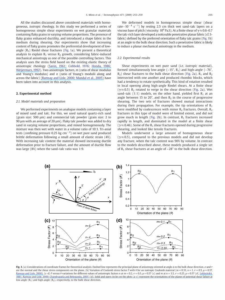
Fig. 3. (a) Considerations of coordinate frames for theoretical analysis. Dashed line representsare the normal and the shear stress components on the plane. (b) Variation of Coulomb strRamsay and Lisle, 2000). (c–d) F versus θ variations for different values of anisotropic factor1981; Ramsay and Lisle, 2000; Chandrupatla and Belegundu, 2001) (d). Solid and open circlelow-angle (R1) and high-angle (R2), respectively, to the bulk shear direction.
We deformed models in homogeneous simple shear (shearrate~10−4 s−1) by resting 2.5 cm thick wet sand–talc layers on aviscous base of pitch (viscosity: 106 Pa.S). At a finite shear ofγ≈0.6–0.7the talc-rich layerdevelopedanoticeable penetrative planar fabric (cf. S-fabric) defined by the preferred orientation of flaky talc grains (Fig. 1b)at an angle to the bulk shear direction. Such a penetrative fabric is likelyto induce a planar mechanical anisotropy in the medium.
2.2. Experimental results
Shear experiments on wet pure sand (i.e. isotropic material),formed simultaneously low-angle (~15°, R1) and high-angle (~76°,R2) shear fractures to the bulk shear direction (Fig. 2a). R1 and R2
intersected with one another and produced rhombic blocks, whichhad a tendency to rotate synthetically. This kind of rotation resultedin local opening along high-angle Riedel shears. At a finite shear(γ≈0.5) R2 rotated to verge in the shear direction (Fig. 2a). Wetsand–talc (1:1) models, on the other hand, yielded first R1 at anangle between 15 to 20°, and then R2 in the course of progressiveshearing. The two sets of fractures showed mutual interactionsduring their propagation. For example, the tip orientations of R1
were modified by coalescences with minor R2 fractures. Overall, R2
fractures in this type of model were of limited extent, and did notgrow much in length (Fig. 2b). In contrast, R1 fractures increasedrapidly in length, and dominated in the model at a finite shear(γ≈0.46). Some of the R1 shear fractures opened during progressiveshearing, and looked like tensile fractures.
Models underwent a large amount of homogeneous shear(γ≈0.5), compared to the previous models and did not developany fracture, when the talc content was 90% by volume. In contrastto the models described above, these models produced a single setof R1 shear fractures at an angle of ~28° to the bulk shear direction.
the principal plane of anisotropy oriented at angle ϕ to the bulk shear direction. σ and τess factor F with θ for an isotropic Coulomb material (m=0.33, n=1, ν=0.5, µ=0.57,s n at m=0.2, ν=0.5, µ=0.57 (c) and m at n=3.5, ν=0.25, µ=0.57 (cf., Lekhnitskii,s on the plots (a–c) represent the orientations of the planes of potential shear failure at

256 S. Misra et al. / Tectonophysics 471 (2009) 253–259
R2 shear fractures were not perceptible on the macro-scale (Fig. 2c).Models at a large finite shear (γ=1.33) had numerous closelyspaced R1 (cf. Fig. 1a), resembling C′-fabrics in mylonites.
To summarize the experimental results, low- and high-angleRiedel shear fractures develop more or less equally in the pure sandmedium. Low-angle fractures become progressively dominating asthe granular medium contains flaky talc with increasing volumeproportions. Experiments show that the amount of homogeneousductile strain is larger for larger talc contents, implying rheological(increasing ductility) changes of the medium. Another changeinvolves an isotropic to anisotropic rheological transition due todevelopment of the shape fabric prior to shear failure. Both theserheological changes might control the process of Riedel shearlocalization in shear deformation, as discussed in a later section.However, we dealt with a theoretical analysis to investigate theprobable controls of mechanical anisotropy in Riedel shear fractur-ing. The analysis is presented in the following section.
3. Theoretical interpretation
3.1. Mathematical formulations
Consider a shear zone containing a shape fabric oriented at anangle of ϕ to the shear boundary and subjected to a bulk simple shearγb (Fig. 3a). A Cartesian coordinate frame, xy, is chosen at the center ofshear zone with x-axis parallel to the bulk shear plane. Forconvenience, we take another Cartesian frame x′y′ with x′ axis alongthe fabric (Fig. 3a). Considering the medium as orthotropic (fabricbeing one of the principal planes of anisotropy), the stresscomponents can be written in terms of the x′y′ reference as:
σ xVxV= K n − m212� �
exVxV + 1 + m13ð Þm12eyVyVh i
ð1aÞ
σyVyV= K 1 + m13ð Þm12exVx V+ 1− m213
� �eyVyV
h ið1bÞ
σ xVyV = G12exVyV ð1cÞ
where K = G12
mn 1 + m13ð Þ 1 − m13 − 2nm212ð Þ (Lekhnitskii, 1981; Ramsay and
Lisle, 2000; Chandrupatla and Belegundu, 2001). v12 and v13 arePoisson's ratios along and across the fabric. For a small amount ofdeformation we consider that the value of v12 and v13 are identical.G12 is the shear modulus along the fabric. m and n are the twoanisotropic factors defined by the following expressions (cf. Cobbold,1976; Honda, 1986; Ramsay and Lisle, 2000, Mandal et al., 2005):
m =G12
E2and n =
E1E2
; ð2Þ
where E1 and E2 are Young's modulii along and across the fabric. Thestrain components in Eq. (1) can be expressed in terms of bulk shearin the shear zone:
exVxV=12γb sin 2/; ex Vy V= − 1
2γb sin 2/ and exVyV= γb cos 2/: ð3Þ
Replacing the expressions of Eq. (3) in Eq. (1), we have
σ⁎xVxV =
L2
n − m212� �
− 1 + m13ð Þm12h i
sin 2/ ð4aÞ
σ⁎yVyV =
L2
1 + m13ð Þm12 + 1− m212
� �h isin 2/ ð4bÞ
σ⁎xVyV= cos2/: ð4cÞ
The stress components in Eq. (4) are normalized to G12γb. L is adimensionless quantity, the expression of which is:
L =1
mn 1 + m13ð Þ 1− m13 − 2nm212� � : ð5Þ
The transformation equation for a second-rank tensor follows,
σ ij = amianjσ Vmn; ð6Þ
where aij =cos/ sin/− sin/ cos/
� �: ð7Þ
With the help of Eqs. (4), (6) and (7), we have
σxx =A + B
2sin 2/ +
A − B4
− 12
� sin 4/
σyy =A + B
2sin 2/ − A − B
4− 1
2
� sin 4/
σxy = cos2 2/ +A − B
2sin2 2/
ð8Þ
where
A =L2
n − m212� �
− 1 + m13ð Þm12h i
andB =L2
1 + m13ð Þm12 + 1− m212� �h i
: ð9Þ
Eq. (8) describes the stress field in the shear zone undergoingsimple shear movement.
In our experiments brittle failure took place through shearfractures. We therefore employ Coulomb–Navier failure criterion tostudy development of shear fractures in shear deformations. Accord-ing to this criterion, shear failure occurs along planes where |τ|+μσ isa maximum, σ and τ are the normal stress and shear stresscomponents on the plane of failure and µ is the co-efficient of friction.σ and τ can be obtained from the following equations.
σ =σxx + σyy
2+
σxx − σyy
2cos 2θ and τ = −
σxx − σyy
2sin 2θ: ð10Þ
θ is the inclination of the normal (n–) to the planewith respect to the x-axis (Fig. 3a). For brevity, |τ|+μσ is expressed as F, which we will callCoulomb stress factor in the following discussions. According to theCoulomb–Navier criterion, the material will fail by shear fracturesalong planes where F is a maximum. Using Eq. (10) we thereforederive the variation of F as a function of θ, and find its maxima. θcorresponding to the maximum value of F defines the orientation ofthe potential plane of shear failure. The analysis was performed withthe help of a computer program developed in the environment ofVisual Basic (Version 6.0). We analyzed F versus θ variationconsidering the two anisotropic factors, m and n and the co-efficientof friction µ. During the analyses, we kept the orientation of the shapefabric at a constant value (ϕ=30°).
3.2. Analysis of R1 versus R2 fracture formation
We first consider a mechanically isotropic medium, and choosem=0.33, n=1, ν=0.5, µ=0.57 (Ramsay and Lisle, 2000). In thisanalysis θwill be varied between 0 and 90° (Katz et al., 2006) becauseRiedel fractures verge opposite to the bulk shear direction. The F–θvariations in this case show two distinct maxima of equal values andsymmetrically disposed at θ ~15 and ~75° (Fig. 3b). According toCoulomb–Navier criterion, these two orientations correspond to thepotential planes of shear failure in shear deformation, as noticed insand-rich models (Fig. 2a).
For anisotropic rheology, F–θ variations turns to define a singlemaximum at θ=75° with increasing n (N4, Fig. 3c). It follows that the

257S. Misra et al. / Tectonophysics 471 (2009) 253–259
conjugate set of Riedel shears will be replaced by a single set of R1
shear fracture if the degree of anisotropy crosses a threshold value.However, the effective stress for Riedel fracturing increases withincreasing n. The anisotropic factorm also exerts a similar effect on F–θ variations (Fig. 3d), implying that increasing mechanical anisotropyfavors formation of low-angle Riedel fractures.
According to the theoretical analysis presented above, both R1 andR2 shear planes can localize in isotropic or moderately anisotropic(nb4) materials, as noticed in sand–talc (1:1) experiments. In theexperiments, the growth of R1 dominated over that of R2 withprogressive shear. R2 remained as a minor set of fractures after a finiteshear (Fig. 2b). Employing the same theoretical method, we can
Fig. 4. Theoretical explanation for contrasting strain softening (reduction in shearmodulus) along R1 and R2 shear bands. (a) Geometrical considerations: θ is theorientation of the normal (n ̅) to the shear plane, α is the inclination of the plane ofanisotropy (fabric) with the band-normal n ̅. (b–c) Contrasting shear softeningparameter (h) with α for R1 and R2 shear bands, respectively.
explain this difference in R1 and R2 growth, considering the effectiveshear modulii along them as
G⁎ = 1 +mn
1 + n − nm
+ 2m12h i
sin2 2α; ð11Þ
where G⁎ =G12GV12
, α is the angle between the plane of anisotropy andthe normal to shear bands (Fig. 4a). G12′ is the band-parallel shearmodulus. Differentiating Eq. (11) with time, it follows
G⁎ =dG⁎
dt= 2
mn
1 + n − nm
+ 2m12h i
sin 4αdαdt
: ð12Þ
Considering shear parallel to the band, we can write
dαdt
= − sin2 αγ̇; γ̇= − γ̇b cos 2θ: ð13Þ
With the help of Eqs. (12) and (13), the rate of shear hardening canbe obtained in terms of the following equation.
h =
:G⁎
γ̇ b = 2mn
1 + n − nm
+ 2m12h i
sin 4α sin2 α cos 2θ: ð14Þ
The parameter h can be considered as a measure of shearhardening (i.e. change in effective shear modulus) along a band,which is negative and positive for shear hardening and softening,respectively. Strain softening, i.e. reducing shear modulus, willpreferentially cause shear localization. Considering the theoreticalresult presented in Section 3 (Fig. 3), we can take θ values between 65and 90° and 0 and 15° for low-angle and high-angle shear bands,respectively. The probable initial values of α for R1 and R2 are +35°and −25°, respectively, when the fabric is assumed to make an angleof 40° to the bulk shear direction. Eq. (14) shows that the parameter his positive when αb45°, and becomes a maximum when α≈35°,implying that there occurs an instantaneous shear softening at thehighest rate along low-angle shear bands (Fig. 4b). In contrast, high-angle shear bands with α=−25° involve shear softening at arelatively lower rate (Fig. 4c).
In order to show the contrasting softening behavior, we haveconsidered specific values for the orientations of shear bands andpenetrative fabric. With progressive shear deformations, the fabricsand the two sets of shear bands are likely to rotate at different rates(Katz et al., 2006). The relative angle α would, therefore, be differentat different instants of progressive shear. Moreover, the fabricorientation can strongly vary due to strain heterogeneity in theneighbourhood of incipient Riedel shear cracks. Thus, the examplecited here is somewhat simplistic. We use this example merely tosuggest that there can be difference in strain softening along R1 and R2
shear bands in anisotropic media.
4. Discussion
We conducted sand–talc experiments to study the nature of Riedelshear localization in simple shear deformation. Our experimentsclearly suggest that low- and high-angle Riedel shear fractures do notgrow equally in granular media, as the talc content increases in itsvolume proportions. Low-angle shear tends to dominate withincreasing talc content, which must have resulted from somerheological transitions. In our experiments the granular medium ofpure sand was almost like a brittle, Coulomb material. Increasing talccontent led the granular medium to be more and more ductile.However, this brittle to ductile transition does not seem to be the solefactor in determining the preferential growth of low-angle fractures,as discussed below.

Fig. 5. (a) Stress factor F versus θ plots for increasing mechanical anisotropy. Solid andopen circles represent failure through R1 and R2 shear planes. Note that the point ofmaxima (open circles) shifts to the negative side of the plot, implying that the potentialplane of shear failure (solid triangle) verges in the bulk shear direction. (b–c) Analoguemodel experiments showing contrasting growth of two sets of shear cracks initiallyinduced at 165° and 80° to the bulk shear direction. Note that shear cracks oriented at165° propagated and linked one another forming R1 Riedel shear, whereas thoseoriented at 80° did not propagate, but rotated passively in the bulk shear direction.
258 S. Misra et al. / Tectonophysics 471 (2009) 253–259
In a recent study Katz et al. (2006) have dealt with Newtonian topower-law rheological transitions to analyze the growth of Riedelshear in ductile materials. They have shown that Riedel shear canlocalize in a power-law medium with exponent factor (n, in theirterminology) N1. This is likely to occur along low- and high-anglebands under instantaneous shear deformations. According to theiranalysis, the two sets of shear bands growat unequal rates due to theirdifferent rotations in progressive shear. High-angle shear bands rotateat a faster rate, and dampen their growth due to their rotation tounfavourable orientations. In case of granular materials, like sand–talcmixtures, the growth of Riedel shear depend also upon the physicalproperties controlling the propagation rate of shear fractures. Forexample, the pure sand medium in our experiments produced bothlow- and high-angle shear fractures, which propagated fast, and grewto large lengths before any significant rotation. With continued sheardeformation, long high-angle fractures rotated like passive markers.On the other hand, the talc-rich medium did not produce any high-angle shear fractures even at the instant of brittle failure. Weapprehend that increasing talc content brought in rheologicaltransitions responsible for the preferential growth of low-angleshear fractures. The transitions could be: 1) brittle to ductile and2) isotropic to anisotropic. Considering the first case, shear fractureswould localize symmetrically with respect to the principal compres-sion direction, which is oriented at an angle of 45° to the sheardirection, irrespective of the ductility of medium, as shown from thetheory for isotropic materials. Thus, two sets of shear fractures wouldnucleate at potential angles of about 15° and 75° at the instant ofbrittle failure. In the talc-rich experiments, high-angle fractures couldgrow during their rotation from 75° to 90° positions, albeit at slowerrates. But such a growth was absent in our experiments. An alternativeexplanation can be as follows. The rate of fracture propagationdecreases with increasing ductility due to larger volume proportionsof talc in the granular medium. Therefore, the growth rate of high-angle shear fractures fails to compete with the rotation rate. Theyrotate to unfavourable orientations before their growth to significantlengths, in contrast to that observed in relatively more brittle sandmodels. However, the rapid growth of low-angle shear suggests thatpre-failure ductility did not influence significantly the development ofRiedel fractures in talc-rich models.
The mechanical anisotropy that develops prior to brittle failureseems to be a plausible factor in dampening the growth of high-angleRiedel fractures. According to the theoretical analysis presented inSection 3, the potential orientations for shear localization vary withincreasing degrees of mechanical anisotropy. The variation appears tobe more pronounced for high-angle Riedel shear fractures. Forisotropic materials, its potential orientations are 75°, which tends tobe greater than 90° as the medium becomes mechanically anisotropic.Therefore, high-angle fractures either lie in or quickly rotate to a strainfield where these involve shortening across them. Consequently, theirgrowth turns to be slow. On the other hand, low-angle shear fracturescontinue to occur in a field with an extensional component acrossthem, and thereby rapidly grow in progressive shear, compared tohigh-angle shear fractures. We thus emphasize that the developmentof Riedel fractures will also be controlled by the mechanicalanisotropy in the granular medium. Our theoretical analysis showsprobable effects of the anisotropy independently. We need to advancethis study considering the independent effects of ductility.
The co-efficient of internal friction of the granular medium can beanother potential rheological factor in determining the growth ofRiedel shear. According to the Coulomb–Navier criterion, the plane ofshear failure makes an angle (θ) to the principal compression axis:θ = π
4 − ψ2 (Jaeger, 1969), where ψ is the angle of friction. In case of
isotropic materials, the principal axis of compression is oriented at anangle of 45° to the shear direction. Thus, two sets of Riedel fracturesare oriented at angle of ψ
2 and π2 − ψ
2. With decrease in ψ, low-angleshear fractures would tend to be parallel, whereas high-angle
fractures would be perpendicular to the shear direction. However,talc-rich medium, apparently with lower co-efficient of friction,contains low-angle Riedel shear at relatively higher inclinations.This is about 28°, in contrast to 15° for pure sand materials. Thevarying orientations of low-angle shear fractures cannot be attributedto the frictional property. Alternatively, we can explain this variationconsidering mechanical anisotropy of the medium. Our theoreticalanalysis shows that low-angle Riedel shear fractures make aninclination of about 15° in case of isotropic materials (m=0.33), asnoticed in sand models. The inclination increases to about 28° foranisotropic materials with m=0.1 (Fig. 3d), as observed in talc-rich
259S. Misra et al. / Tectonophysics 471 (2009) 253–259
experiments. This experimental finding indicates that the mechanicalanisotropy has played a role in the process of shear failure in talc-richgranular materials.
In order to analyze relative development of R1 and R2 shear fractureswe considered the variation of Coulomb stress factor for planes withnormal at an angle between0 and90° to the bulk sheardirection (Fig. 3a).The stress is found to have a single maximum in this antithetic rangewhen the shearedmedium ismechanicallyanisotropic (Fig. 3c andd).Weran a few computations encompassing planes with normal making anegative angle to the bulk shear plane and to represent the result weextend the θ axis from −15 to 90°. These runs showed that withincreasing mechanical anisotropy the plane of maximum Coulomb stressprogressively rotate towards thedirectionof applied shear (Fig. 5a),whichimplies that the orientation of the second set of shear failure is likely tooccur on planes at an angle less than 0°, i.e. with opposite vergence(Fig. 5a). However, oppositely verging shear fractures were not producedin our experiments. To test the growth of high-angle shear planes, weperformed a set of physical experiments on sand–talcmodels (containing90% talc, by volume)with pre-existing cuts in two populations. Individualcracks in the twopopulationswere oriented at an angle of 80° and 165° tothe shear direction (Fig. 5b).Model deformation showed that cracks at anangle of 165° began to propagate fast following homogeneous ductileshear strain, and produced low-angle Riedel fractures (Fig. 5c) with littleor no rotation. In contrary, cracks in the other population remain virtuallyintact, and rotatedaspassivemarkers.Withprogressivedeformation theirinclinationwasmore towards the direction of applied shear. Based on thisexperimental finding, we suggest that the second set of failure planes inanisotropic materials, undergoing simple shear deformation, probablynucleate, but their growth fails to compete with that of R1 shear.
There are some limitations in our study. Firstly, the granularmaterial was extremely soft. Thus, it has not been possible to measurerheological parameters, like Young's modulus and shear modulus,which was necessary for estimation of the anisotropic factors used inthe theoretical analysis. We have inferred qualitatively themechanicalanisotropy from the presence of a penetrative shape fabric in the talc-rich granular materials. Secondly, our theoretical study takes intoaccount arbitrary values of the anisotropic factors. Some values aresomewhat exaggerated in order to show the effect of mechanicalanisotropy more explicitly.
5. Conclusions
Based on the experimental and theoretical results we arrive at thefollowing conclusions. 1) In granular materials, the development ofRiedel shear fractures depends on the grain constituents that control therheologyand themechanical properties of thematerials. (2) Rheological(brittle to ductile) changes and the penetrative shape fabrics of flakygrain constituents in the granular materials appears to be potentialfactors in determining the relative growth of low- and high-angle Riedelshear fractures. The two sets of fractures develop equally only when thegranular materials are mostly brittle, and do not contain any shapefabric. On the other hand, they develop in a single set, at a low-angle tothe bulk shear direction as the materials become ductile and contain ashape fabric of flaky grains (volume proportionsN90%). 3) Mechanicalanisotropy imparted by the shape fabric of flaky grains largely governsthe process of Riedel shear formation. For isotropic materials, theCoulomb stress becomes a maximum on two oppositely verging planesat an angle of 15 and 75° to the bulk shear direction. With increasinganisotropy the stress shows a single maximum between 0–90°,corresponding to low-angle Riedel shear fractures. 4) In anisotropicmedia low-angle Riedel shears involve relatively higher strain softeningand grow at relatively higher rates.
Acknowledgements
The manuscript has been greatly improved by the comments of twoanonymous reviewers. We are grateful to Professor Tom Parsons forgiving us a guideline for revision. We thank Professor Neil Mancktelowfor his valuable comments on an early version of the manuscript. Thework has been carried out under a project of the Department of Scienceand Technology, India, and a research fellowship of SM from Council ofScientific and Industrial Research (CSIR), India.
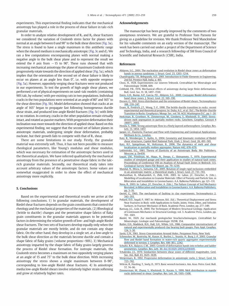
References
Ahlgren, S.G., 2001. The nucleation and evolution in Riedel shear zones as deformationbands in porous sandstone. J. Struct. Geol. 23, 1203–1214.
Chandrupatla, T.R., Belegundu, A.D., 2001. Introduction to Finite Elements in Engineering,2nd Ed. Prentice Hall, India, p. 461.
Cloos, H., 1928. Experimenten zur inneren Tektonik. Centralblatt fur Mineralogie andPaleontologie 1928B, 609.
Cobbold, P.R., 1976. Mechanical effects of anisotropy during large finite deformations.Bull. Geol. Soc. Fr. 18, 1497–1510.
Davis, G.H., Bump, A.P., Garcia, P.E., Ahlgren, S.G., 2000. Conjugate Riedel deformationband shear zones. J. Struct. Geol. 22, 169–190.
Dresen, G., 1991. Stress distribution and the orientation of Riedel shears. Tectonophysics188, 239–247.
Evans, B., Fredrich, J.T., Wong, T.-F., 1990. The brittle ductile transition in rocks: recentexperimental and theoretical progress. In: Duba, A.G., et al. (Ed.), The Brittle–DuctileTransition in Rocks. Geophysics.Mongr. Ser., vol. 56. AGU,WashingtonD.C., pp.1–20.
Holtzman, B., Groebner, N., Zimmerman, M., Ginsberg, S., Kholstedt, D., 2003. Stress-driven melt segregation in partially molten rocks. Geochem. Geophys. Geosyst 4(8607), 2003.
Honda, S., 1986. Strong anisotropic flow in a finely layered asthenosphere. Geophys. Res.Lett. 13, 1454–1457.
Jaeger, J.C., Elasticity, Fracture and Flow with Engineering and Geological Applications.Methuen & Co., London.
Katz, R., Weinberger, Y., Aydin, A., 2004. Geometry and kinematic evolution of Riedelshear structures, Capitol Reef National Park, Utah. J. Struct. Geol. 26, 491–501.
Katz, R.F., Spiegelman, M., Holtzman, B., 2006. The dynamics of melt and shearlocalization in partially molten aggregates. Nature 442, 676–679.
Lekhnitskii, S.G., 1981. Theory of Elasticity of an Anisotropic Body. Mir Publishers,Moscow, p. De430.
Logan, J.M., Friedman, M., Higgs, N., Dengo, C., Shimamoto, T., 1979. Experimentalstudies of simulated gouge and their application to studies of natural fault zones.Proceedings of Conference VIII on Analysis of Actual Fault Zones in Bedrock: U.S.Geological Survey Open-File Report, pp. 79–1239.
Mandal, N., Misra, S., Samanta, S.K., 2005. Rotation of single rigid inclusions embeddedin an anisotropic matrix: a theoretical study. J. Struct. Geol. 27, 731–743.
Muhunthan, B., Alhattamleh, O., Zbib, H.M., 2003. In: Labuz, J.F., Drescher, A. (Eds.),Modelling of Localization in Granular Materials: Effect of Porosity and Particle Size, inBifurcation and Instabilities in Geomechanics. A.A. Balkema Publishers, pp. 121–131.
Nova, R., 2003. In: Labuz, J.F., Drescher, A. (Eds.), The Failure Concept of Soil MechanicsRevisited, in Bifurcation and Instabilities in Geomechanics. A.A. Balkema Publishers,pp. 3–16.
Oertel, G., 1965. The mechanism of faulting in clay experiments. Tectonophysics 2,343–393.
Pollard, D.D., Segall, P., 1987. In: Atkinson, B.K. (Ed.), Theoretical Displacement and StressNear Fractures in Rock: with Applications to Faults, Joints, Veins, Dikes, and SolutionSurfaces, in Fracture Mechanics of Rock. Academic Press, London, pp. 277–349.
Ramsay, J.G., Lisle, R., 2000. The Techniques of Modern Structural Geology. Applicationof Continuum Mechanics in Structural Geology, vol. 3. Academic Press, London, pp.701–1601.
Riedel, W., 1929. Zur mechanik geologischer brucherscheinungen. Centralblatt furMinerologie, Geologie und Paleontologie 1929B, 354.
Rutter, E.H., Maddock, R.H., Hall, S.H., White, S.H., 1986. Comparative microstructures ofnatural and experimentally produced clay bearing fault gouges. Pure Appl. Geophys.124, 3–30.
Savin, G.N., 1961. Stress Concentration Around Holes. Pergamon Press, New York.Schmocker, M., Bystricky, M., Kunze, K., Burlini, L., Stunitz, H., Burg, J.-P., 2003. Granular
flow and Riedel band formation in water-rich quartz aggregates experimentallydeformed in torsion. J. Geophys. Res. 108 (B5), 2242.
Schultz, R.A., Balasco, C.M., 2003. Growth of deformation bands into echelon and laddergeometries. Geophys. Res. Lett. 30. doi:10.1029/2003GL018449.
Tchalenko, J.S., 1970. Similarities between shear zones of different magnitudes. Geol.Soc. Am. Bull. 81, 1625–1639.
Weijermars, R., 1992. Progressive deformation in anisotropic rocks. J. Struct. Geol. 14,723–742.
Wilcox, R., Harding, T., Seely, D.,1973. Basic wrench tectonics. Am. Asso. Petro. Geol. Bull.57, 74–96.
Zimmerman, M., Zhang, S., Kholstedt, D., Karato, S., 1999. Melt distribution in mantlerocks deformed in shear. Geophys. Res. Lett. 26, 1505–1508.