GOCE: ESA's first Earth Explorer Core mission - European ...
Upload
independentCategory
view
1download
0
Flying at the Edge – Extremely Low Altitude Operations for ESA’s Drag-Free Gravity Mission GOCE
Christoph Steiger1, Massimo Romanazzo2, Pier P. Emanuelli3 ESA/ESOC, Robert-Bosch Str. 5, 64293 Darmstadt, Germany
Rune Floberghagen4 ESA/ESRIN, Via Galileo Galilei, 00044 Frascati, Italy
and
Michael Fehringer5 ESA/ESTEC, Keplerlaan 1, 2200 AG Noordwijk, Netherlands
ESA’s Gravity Field and Steady-State Ocean Circulation Explorer (GOCE) has been operated from launch in 2009 up to mid-2012 in a very low Earth orbit at an altitude of 260 km. The spacecraft design features a unique aerodynamic shape and employs drag-free control with an ion propulsion system to counteract the atmospheric drag. While the routine mission of GOCE has been very successful, it is inevitably coming to an end once all consumables are exhausted. To maximize the scientific return of the mission prior to its end of life, ESA has implemented a campaign to lower the orbit of GOCE even further, culminating in May 2013 with reaching the new science altitude of 229 Km. This constituted a challenging endeavour, requiring major re-evaluations and changes on both space and ground segment. This paper presents the planning and execution of the low orbit operations campaign.
I. Introduction he Gravity Field and Steady-state Ocean Circulation Explorer (GOCE) was selected in 1999 as the first mission of ESA’s Living Planet Programme. After nearly a decade of development, GOCE was launched on 17th March
2009.
A. GOCE Mission Overview GOCE’s scientific objective is to measure the Earth’s gravity field and to provide a model of the geoid with
unprecedented accuracy, determining gravity field anomalies with an accuracy of 1 mGal (or 10−5 m/s2), and the geoid to an accuracy of 1 to 2 cm at a spatial resolution of 100 km. The high accuracy expected for GOCE’s gravity field model is in particular essential for precise determination of ocean circulation. GOCE data will also be used for leveling by GPS, navigation, continental lithosphere studies and for global unification of height systems, e.g. to establish a global sea-level monitoring system.
GOCE is the first spacecraft employing the concept of gradiometry, i.e. the measurement of acceleration differences over short baselines between proof masses of a set of accelerometers of the Electrostatic Gravity Gradiometer (EGG). The EGG is used to measure high-resolution features of the gravity field, while large-scale phenomena in the gravity field are obtained through analysis of the spacecraft’s orbit as measured with a scientific GNSS receiver on-board the spacecraft, the Satellite-to-Satellite Tracking Instrument (SSTI).
1 GOCE Spacecraft Operations Manager, Mission Operations Department, ESA/ESOC Darmstadt, Germany. 2 GOCE Spacecraft Operations Engineer, Mission Operations Department, ESA/ESOC Darmstadt, Germany. 3 Head of Earth Observation Missions Division, Mission Operations Department, ESA/ESOC Darmstadt, Germany. 4 GOCE Mission Manager, Earth Observation Ground Segment & Mission Operations Department, ESA/ESRIN Frascati, Italy. 5 GOCE Satellite System Manager, Earth Observation Projects Department, ESA/ESTEC Noordwijk, Netherlands.
T
American Institute of Aeronautics and Astronautics
1
To obtain a sufficiently strong gravity field signal, GOCE is in a sun-synchronous Earth orbit at an exceptionally low altitude of around 260 km, where the density of the Earth’s atmosphere is significant. GOCE is specifically designed for minimising air drag forces and torques, possessing the capability to counteract the drag and cancel out non-gravitational forces. The actual altitude is chosen according to the current solar activity level, which drives the atmospheric drag forces encountered.
GOCE is operated by the European Space Operations Centre (ESOC) in Darmstadt, Germany. Science data is processed and archived by the Payload Data Ground Segment (PDGS) at ESRIN in Frascati, Italy. Further processing is done by the High-level Processing Facility (HPF), operated under ESA contract by the European GOCE Gravity Consortium.
See Ref. 1, 2 and 6 for general information on the mission.
B. The GOCE Spacecraft GOCE was built under ESA contract by a
consortium led by Thales Alenia Space Italy, with EADS Astrium Germany responsible for the platform, and Thales Alenia Space France for the gradiometer.
The specifics of the GOCE mission drive the spacecraft design. As far as possible, the spacecraft has to be free of non-gravitational forces to not disturb gradiometer measurements. To minimize aerodynamic drag forces and torques, the spacecraft structure is a slim octagonal design (about 4.8 m long with a cross section of 1.1 m2, launch mass 1050 kg), fully symmetric and with winglets for additional aerodynamic stability (Fig. 1). Table 1 contains an overview of the characteristics of GOCE’s subsystems. The following major elements set GOCE apart from more conventional Earth observation spacecraft:
Drag-free Attitude and Orbit Control System (DFACS): The DFACS provides 3-axis stabilised attitude control with magnetic torquers as actuators. An ion propulsion assembly (IPA) is used for continuous, closed-loop counteraction of atmospheric drag. To minimize internal disturbances, the satellite has no moving parts (like e.g. reaction wheels). The absence of strong actuators leads to complex attitude control laws sensitive to environmental changes. There is no clear distinction between platform and payload: EGG and SSTI are used in closed loop when in drag-free mode.
Electrostatic Gravity Gradiometer (EGG): The EGG contains three accelerometer pairs mounted on an ultra-stable carbon-carbon honeycomb support structure. For each accelerometer a proof mass is kept in the centre of the cage by electrostatic forces representative of the accelerations seen by the mass. The accelerations measurable are as small as one part in 10’000’000’000’000 of the gravity experienced on Earth, making these units about 100 times more sensitive than any accelerometers previously flown.
Figure 1. Artist’s impression of the spacecraft.
American Institute of Aeronautics and Astronautics
2

C. Flight Operations Setup and Approach Figure 2 gives an overview of the main facilities
and interfaces of the GOCE Flight Operations Segment (FOS) at ESOC. The FOS incorporates all systems required for operating GOCE, and is implemented following the standard approach for ESA missions. ESA’s Kiruna station in Sweden is the prime station for GOCE. The SvalSat station in Svalbard of Kongsberg Satellite Services AS (KSAT) is used to augment the Kiruna station passes. In addition, KSAT’s Troll station in Antarctica was used during the routine phase for contingency support. In routine, every day 6 Kiruna station passes are taken, augmented by 1 to 2 passes on the SvalSat station. As from the start of the low orbit operations campaign, an additional Troll contact is taken around midnight to close the night visibility gap from Kiruna and Svalbard and allow early detection of spacecraft anomalies.
Due to the very low operational altitude, the GOCE Mission is characterised by very short ground contacts (up to a maximum of 6 minutes of commanding duration) and gaps between subsequent ground contacts lasting up to 12 hours. As a consequence of GOCE’s short pass durations, the routine pass activities are automated as much as possible, with virtually all pass-related activities (e.g. connection of links to ground station, start and stop of mass memory playback) performed through an automatic release-based stack running on the mission control system, or by time-tagged command from the on-board mission timeline.
Orbit determination and prediction is performed daily based on the S/C position vector obtained from the SSTI, with the orbit prediction having to take into account the S/C mode (drag-free or in decay). Deviations with respect to the planned S/C mode need to be immediately communicated to the orbit prediction system to generate new predictions and update them at the ground stations. Orbit determination can also be based on ranging data, however this is nominally not done as it would require establishment of a low bit rate TM mode, which would not allow the dump of playback data.
The main interface of the FOS is with the PDGS at ESRIN, with the FOS providing all playback telemetry dumped from the spacecraft in raw format, and planning-related information exchanged between the two entities. Further interfaces not indicated in the figure are with GOCE mission management (at ESRIN) and with the S/C manufacturer, e.g. for the delivery of flight software patches.
Table 1. Spacecraft subsystem characteristics.
Figure 2. Overview of the GOCE Flight Operations Segment (FOS) at ESA/ESOC.
American Institute of Aeronautics and Astronautics
3

D. Mission profile 2009-2012 GOCE was built for a sun-synchronous, near-circular orbit with an inclination of 96.7 deg and ascending node at 18:00 local solar time (Dusk-Dawn). A peculiarity of the mission is that it has not been designed for a particular, fixed reference orbit. Altitude selection is driven by several factors: while a low altitude is beneficial for science, it is constrained by the higher atmospheric drag which shall not exceed the S/C design limits. In addition, the ground track has to be such that the objective of retrieving the Earth’s geopotential at spatial scales down to 100 km can be reached around the globe, requiring to select an orbit with a sufficiently high repeat cycle.
Figure 3 shows the mission profile in terms of altitude and eclipse pattern before start of orbit lowering activities in summer 2012. The routine science operations phase of the mission was performed at 259.6 km altitude (slightly lower than originally planned), offering a favourable repeat cycle of 61 days (979 revolutions). Owing to the very low altitude of its sun-synchronous orbit, the S/C originally experienced 2 eclipse seasons per year. A significant evolution in the eclipse pattern has taken place, as the S/C design only allows to do in-plane manoeuvres to control the semi-major axis. The Local Time of Ascending Node (LTAN) of the orbit is hence left to drift. As of 2011, there is no eclipse-free period between the former eclipse seasons, hence the S/C is in eclipse season for most of the year.
Figure 4 shows the evolution of the ion propulsion thrust in drag-free mode needed to compensate the atmospheric drag. The increase in solar activity towards the upcoming solar maximum had a noticeable impact on the drag levels.
For more details about GOCE flight operations and evolution of the mission profile during the routine phase, see Ref. 3, 4 and 7.
Figure 3. Altitude and eclipse pattern from launch up to May 2012. The change in the eclipse pattern is due to drift of the inclination. Spikes in the mean altitude plot after end of commissioning (Sept 2009) indicate interruptions of science operations in drag-free mode (decay of the orbit due to uncompensated atmospheric drag).
Figure 4. IPA thrust in routine operations to compensate the air drag, showing instantaneous thrust and thrust averaged over each orbit. The variations are caused by changes in solar and geomagnetic activity.
American Institute of Aeronautics and Astronautics
4
II. The Drag-Free Control System This chapter describes the DFACS. See Ref. 5, 8 and 9 for more information on DFACS design and in-flight
experience.
A. Attitude and Orbit Control Requirements GOCE implements two measurement techniques for the gravity field recovery (Ref. 8):
• Gravity gradient measurements by the EGG; • Precise Orbit Determination (POD) by Global Positioning System (GPS).
The two techniques are complementary. POD allows reconstructing with high accuracy the lower harmonics of the gravity field, while the EGG provides better performance at the medium and high harmonics. The intersection is somewhere around Earth gravity field degree and order equal to 15. This leads to the definition of the Measurement Bandwidth (MBW) for the EGG from 5 to 100 mHz, the frequency region where the measurement accuracy of the gravity gradients is maximized. The EGG-measured signals correspond to the gradients of the components of the gravity acceleration along three orthogonal axes, i.e. to the second derivatives of the gravitational potential.
The S/C design is driven by the need for a very quiet environment. Therefore, the attitude control is performed uniquely via magnetic actuators enforced by a passive aerodynamic stabilisation.
Non gravitational accelerations, e.g. due to air drag, affect all EGG accelerometers in the same manner and can theoretically be cancelled out when taking differences between acceleration readings along the same axis (differential acceleration signals). The common mode acceleration signal –resulting from the average of acceleration readings along the same axis– is the DFACS input signal, while the differential acceleration signals constitute the scientific signal. Misalignments and imperfections of the individual accelerometers cause a fraction of the common mode acceleration to leak into the differential channels.
The drag-free control has the task of reducing the non-gravitational linear accelerations below a threshold compatible with the accelerometer dynamic range and with the gradiometric performance, when coupled to the gradiometer imperfections and residual accelerometer non-linearity effects. For the same reason, the attitude control must constrain the angular accelerations and the angular rates maximum value and stability. The DFACS implements a 4 degrees of freedom control, using an ion thruster for linear axis control and magnetic torquers (MTR) for three axis angular control. The linear axis control in the in-flight direction allows to dynamically compensate for the effects of the atmospheric drag.
B. DFACS Sensors and Actuators The DFACS uses the following sensors: • Three hot redundant autonomous star trackers (STR), providing high accuracy and autonomous inertial
attitude determination from “lost in space” conditions; • Two hot redundant Digital Sun Sensors (DSS), providing high accuracy sun vector information; • A Coarse Earth and Sun Sensor (CESS) consisting of 6 sensor heads, providing robust attitude line of sight
measurements with respect to the Sun and Earth for initial acquisition and coarse pointing (safe) mode; • Three 3-axis fluxgate magnetometers (MGM), used for magnetic torquer control and as rate sensors. The
readings from the three MGM on each axis are subject to a 2 out of 3 majority voting scheme. The DFACS uses the following actuators: • Two Ion Propulsion Assembly (IPA) units operated in cold redundancy, for linear drag free control and orbit
semi-major axis control. The IPA is based on a ‘Kaufman’-type electron bombardment ion motor running on Xenon gas. The thrust can be in the range from 0.6 mN to 20 mN, providing a resolution of 12 μN and a slew rate up to 2.5 mN/s.
• Three internally redundant magnetic torquers (MTR) for attitude control. Two operating modes are implemented: Coarse Mode (±0.5A, switching regulation, dead band around zero crossing) and Fine Mode (for scientific mode only; ±0.05A, continuous regulation, 0.05mA/√Hz noise spectral density);
• One internally redundant Gradiometer Calibration Assembly (GCA), constituted by a cold-gas propulsion system (8 thrusters), used to shake the satellite for EGG calibration purposes.
The DFACS sensors and actuators work at different sampling frequencies: EGG and IPA @ 10 Hz; STR, DSS, MGM and MTR @ 2 Hz; CESS, SSTI and GCA @ 1 Hz.
The DFACS also uses data from two payloads in closed loop: the Electrostatic Gravity Gradiometer (EGG), for the gravity measurements and the Satellite to Satellite Tracking Instrument (SSTI) for GPS measurements.
American Institute of Aeronautics and Astronautics
5

Electrostatic Gravity Gradiometer (EGG): The EGG consists of three pairs of three-axis accelerometers mounted in a diamond configuration on ultra-stable
Carbon/Carbon honeycomb panels. Each accelerometer can measure linear accelerations along three orthogonal axes. Each accelerometer pair forms a 0.5 m long gradiometer arm, with the difference in gravitational pull measured between the two ends. The three arms are mounted orthogonally and are aligned with the along-track, cross-track and vertical directions. The functional modules of the gradiometer include:
• Six three-axis accelerometer units, called Accelerometer Sensor Head (ASH); • Three internally redundant Front End Electronic Units (FEEU); • One internally redundant Gradiometer Accelerometer Interface Electronic Unit (GAIEU); • One internally redundant Thermal Control Electronic Unit (TCEU). The ASH (see Fig. 5) is based on the electrostatic suspension of a proof mass (Platinum-Rhodium, 320g,
4x4x1cm³) maintained motionless with respect to the cage in a given bandwidth. The active control (1 kHz sampling frequency) of the 6 degrees of freedom in translation and rotation is through 8 pairs of electrodes, used by both capacitive sensors and electrostatic actuators. Each of the 3 accelerometer pairs on its ultra-stable baseline measures the gravity gradient used to reconstruct the gravity field. The GAIEU provides output data from a scientific channel and a DFAC channel. The output values for the scientific channel are the measured electrodes voltage (FEEU readout), and for the DFAC channel the commanded electrode voltages (FEEU DAC input).
Two EGG calibrations aimed at measuring and adjusting the Quadratic factors (K2) and the Inverse Calibration Matrices (ICM) elements respectively are foreseen to reduce gradiometer measurement errors. While the K2 calibration is performed at EGG unit level through a shaking of the proof masses, the ICM calibration is performed at system level via a shaking of the S/C for a duration of 24 hours using the IPA and the GCA as actuators.
Satellite-to-Satellite Tracking Instrument (SSTI): The SSTI is a state-of-the-art GPS receiver capable of determining a navigation solution tracking GPS signals
from up to 12 GPS satellites. GOCE embarks two SSTI units operated in cold redundancy. Besides providing real-time navigation data with conventional accuracy, the SSTI accurately measure pseudo-
ranges and integrated carrier phase (raw data), to be later processed on ground for scientific purposes, making it ideally suited for Precise Orbit Determination applications. The receiver processes the received GPS signals in both the L1 and L2 frequency bands, allowing compensation of ionosphere delays. The instrument is equipped with one hemispherical-coverage antenna mounted with the bore-sight aligned with the Zenith direction. The SSTI provides at 1Hz C/A code range on L1, P(Y) code range on L1 and L2, carrier phase on L1 and L2, Time measurements.
a), b), c) Figure 5. Electrostatic Gravity Gradiometer. (a) ASH, (b) core consisting of three orthogonally mounted pairs of ASHs, and (c) global view of ASHs and electronic units.
American Institute of Aeronautics and Astronautics
6
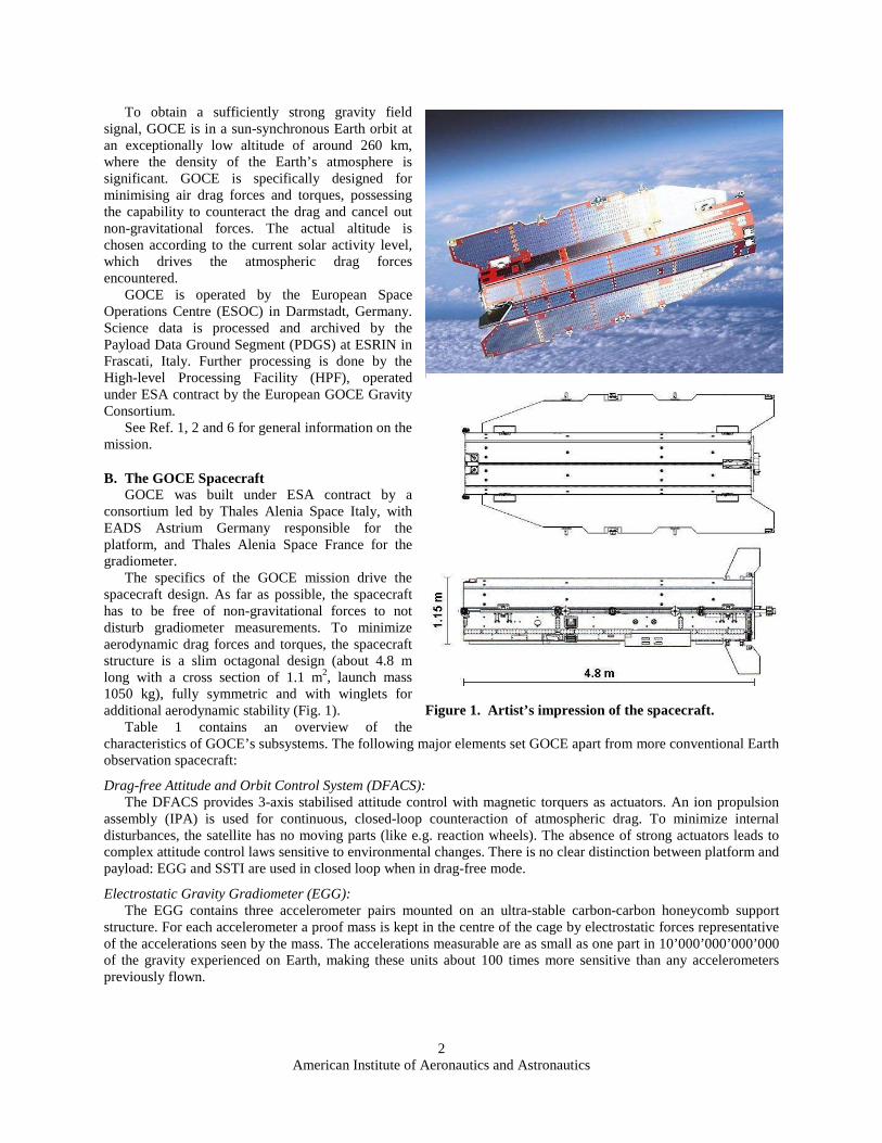
C. DFACS Modes Definition and Control Design The DFACS provides 3-axis stabilised Earth-pointing attitude in all modes, which include Coarse Pointing Mode
(CPM), Extended Coarse Pointing Mode (ECPM), Fine Pointing Mode (FPM) and the Drag-Free Modes (DFM_PREP, DFM_COARSE, DFM_FINE). Table 2 shows the sensors and actuators used in each DFAC mode:
• CPM is an acquisition mode as well as an FDIR-triggered survival mode. In CPM, a stable pointing with respect to Sun and Earth is achieved. CPM was designed to cope with an angular rate at separation from the launcher of up to 1°/s on each axis and to guarantee Sun acquisition in less than 5 hours.
• ECPM improves the LORF pointing to limit the altitude decay and to ensure the star trackers are not affected by the Earth limb, allowing a transition to the next mode (FPM). Compared to CPM, the pointing accuracy is improved due to a better LORF definition making use of the SSTI, and due to an enhanced attitude determination algorithm using an Earth Magnetic Field model and a Sun propagator.
• FPM is the normal non drag-free operating mode during mission phases when orbit decay is required. The attitude is determined using Star Tracker data. The target attitude is defined by a reference generator driven by SSTI data, as used in all modes except CPM.
• DFM_PREP: the IPA is switched on and operated at a constant thrust level to maintain the orbit. The EGG can be switched on out of the control loop. The MTR are operated in Coarse Mode.
• DFM_COARSE: the EGG is in acquisition mode (i.e. with enlarged dynamic range and with coarse measurement accuracy) and the IPA is used in closed loop exploiting coarse EGG measurements, to perform a first-level linear drag-free control in the along-track direction. Angular acceleration reduction is still based on STR measurements. The MTR are operated in Fine Mode.
• DFM_FINE: the EGG is in science mode (i.e. with a smaller dynamic range, but very high measurement accuracy). Linear and angular acceleration control is performed using fine EGG measurements. STR measurements are employed to recover angular acceleration low frequency noise. The in-flight calibration of the gradiometer is also performed in DFM_FINE. The MTR are operated in Fine Mode.
III. The Low Orbit Operations Scenario
A. Rationale for Lowering GOCE’s Orbit The routine scientific mission of GOCE at 260 km altitude has been very successful. Thanks to lower than
expected drag levels, the mission has already operated longer than the originally planned 20+10 months, resulting in an excellent quality of the scientific data.
Owing to the limited amount of consumables on-board, the end of mission was inevitably coming up in early 2014 at the latest. While continuing to operate at 260 km would further reduce the noise in the scientific data, it would not yield major improvements. The only way to achieve this is to lower the orbit. This has driven ESA to plan and implement a new mission profile entailing a major lowering of the orbit, expected to yield tremendous scientific benefits.
As the mission had been designed for a specific altitude range and environment, implementing a lowering of the orbit is not straightforward. The question is how much the orbit can be lowered without putting the mission at undue
Table 2. Usage of sensors and actuators in the various DFACS modes.
MGM DSS CESS STR EGG SSTI MTR IPA GCA
CPM • • • • (5) ECPM • • • • • (5) • (2) FPM • • • • (5)
PREP • • • • (5) • (3) COARSE • • • (1) • • • DFM FINE • • • • • • • (4)
(1) EGG in acquisition mode (2) IPA commanded at constant thrust (open-loop) for emergency orbit maintenance (3) IPA commanded at constant thrust (open-loop) (4) Only when in-flight EGG calibration is requested (5) Coarse current driver
American Institute of Aeronautics and Astronautics
7

risk, while still achieving a significant improvement of the scientific return. This requires realistic modelling of environmental conditions at lower orbits, and an evaluation of the S/C performance in such conditions. The major elements of this assessment are presented in the following sections, covering the modelling and assumptions on the expected environmental conditions (III.B), the definition of reference cases for assessing the feasibility of contingency recoveries (III.C), an assessment of the expected S/C performance (III.D) and the selected altitude profile (III.E). The planning of the GOCE low orbit operations campaign was kicked off in early 2012, with the altitude lowering operations starting in July 2012. The actual environmental conditions at the altitudes reached by the spacecraft as the lowering was progressing were closely monitored. The predictions on the solar activity and density levels were reassessed in early 2013 and used to fine tune the final target altitude selection.
B. Assumptions on Atmospheric Density at 260 km and below A key factor in assessing operations at low orbits are the underlying assumptions for the expected density of the
atmosphere, in turn largely driven by solar and geomagnetic activity. Due to the latter, it is very difficult to perform long term predictions of the density levels with a high degree of accuracy. As the orbit lowering campaign progressed, a re-assessment of the expected density levels at lower orbits was performed in 2013 based on the latest solar activity and density predictions in flight data. This allowed to fine tune the final target altitude selection, going 10 km lower than what was originally planned in early 2012.
ESA/ESOC Flight Dynamics used the NASA MSFC predictions to model the expected evolution of solar activity. The MSISE00 model was used for the atmospheric density. The resulting predicted evolution of solar activity indices and atmospheric density can be seen in the following figures:
• Figure 6 shows the evolution of the F10.7 and Ap indices based on the March 2012 and April 2013 MSFC bulletin, for the 5%, 50% and 95% percentile. Although the Ap index predictions did not change significantly, the solar radio flux F10.7 index shows a significant reduction, from 140 to slightly above 120 for July 2013 (50% percentile).
• Figure 7 shows the predicted atmospheric density based on the MSISE00 model for altitudes from 259.6 km down to 225 km, assuming solar activity as per the March 2012 and April 2013 MSFC bulletins, 95% percentile. The predictions performed in April 2013 show a significant decrease of the density levels compared to the results obtained in March 2012, allowing a significant re-evaluation of the final altitude selection.
The actual evolution of the solar activity and density levels during the altitude lowering activities will be discussed in section IV.B.
a), b) Figure 6. Evolution of the F10.7 and Ap indices, based on (a) the March 2012, and (b) the April 2013 MSFC bulletins (5%, 50% and 95% percentile).
American Institute of Aeronautics and Astronautics
8

C. Altitude Decay Reference Cases Provided that the performance of drag-free mode and hence the quality of the scientific measurements can be
maintained at lower altitudes and higher drag levels, a main driver for determining by how much the orbit can be lowered is S/C safety: in case of an interruption of drag-free mode and a resulting decay of the altitude, ground must resume firing of the ion propulsion system in due time, before the increase of drag due to the altitude decay would become unrecoverable.
Concerning the assumed duration of the decay phase following a S/C contingency, the FOS was originally designed to cope with an outage of the ion propulsion system for a duration of 8 days: in case of an interruption of drag-free mode, the FOS would have to react within 8 days to stop the orbital decay. For the low orbit operations, this time was reduced to 2 days –the minimum time deemed necessary to reliably deal with the recovery of major S/C contingencies–, while also evaluating an intermediate case with 4 days recovery time. This reduction of the recovery time required important changes to the FOS setup originally put in place for an 8-days outage.
The magnitude of the decay depends on the environmental conditions and the S/C mode. The following assumptions were taken:
• Environmental conditions: atmospheric density was assumed to be in line with the worst case density as per the March 2012 MSFC bulletin, 95% percentile. In addition, a geomagnetic storm was assumed to take place in the first few days of the decay. The environmental conditions were re-assessed in 2013 based on the April 2013 MSFC bulletin, 95% percentile, allowing for a tuning of the final altitude selection (see III.B).
• DFACS mode: pointing accuracy varies depending on the mode (CPM, ECPM, FPM), thereby significantly influencing the drag force impacting the S/C and hence the decay rate. For the decay scenarios, transitions from CPM up to FPM (which take place autonomously in case a major S/C contingency results in a fallback from DFM_FINE to CPM) were assumed at the start of the decay, followed by a stay in FPM for the remainder of the decay phase. The corresponding S/C drag coefficient profile to model the mode transitions was selected based on in-flight experience.
• DFACS mode and IPA thrust for altitude recovery: the DFACS was assumed to be in DFM_PREP with a thrust level compatible with the S/C power budget and allowing the recovery of the science altitude within
a), b) Figure 7. Atmospheric density predictions, based on the MSISE00 model and (a) March 2012, and (b) April 2103 MSFC bulletins (95% percentile). The density peak in October 2013, highlighted by the arrows, shows a significant reduction.
Figure 8. Decay reference profiles for starting altitude of 251 km, 244.6 km, 239.6 km (all based on March 2012 density predictions), and a decay reference profile for 230 km (based on lower April 2013 density predictions).
American Institute of Aeronautics and Astronautics
9

a predefined time. Based on these assumptions, the minimum altitudes allowing a recovery after a decay phase of 8 days, 4 days and 2 days were evaluated in 2012 to be 251 km, 245 km, and 240 km, respectively. The low orbit operations scenario reassessment performed in April 2013 and based on the latest solar activity and density predictions allowed to update the minimum altitude corresponding to the 2 days recovery case to 229 km. Figure 8 shows the evolution of the altitude for each reference case. Figure 9 shows plots on the evolution of the altitude, atmospheric density and drag for the 2-days-outage scenario as reassessed in 2013. The simulated geomagnetic storm at the start of the decay phase is clearly visible.
D. Assessment on S/C Performance
Drag-free Control System (DFACS): The drag-free control system has been designed for certain ranges of densities depending on the DFACS mode,
which are exceeded for the conditions assumed for the reference decay scenarios. To evaluate DFACS performance, the S/C manufacturer has run simulations on a high fidelity End-to-End simulator (as used in development), with environmental conditions representative of the lowered orbit. All DFACS modes were found to work, with only little tuning activities required:
• CPM: while no major issues had been identified and the steady-state performances were found to be excellent, the duration of the initial rate damping phase in a high drag environment was found to be longer, which in one isolated simulation scenario led to the triggering of a timeout surveillance.
• ECPM: the performance strongly depends on the quality of the CESS data. Initially the mode was found to diverge in some specific cases, however when tuning the CESS model of the simulator to have an accuracy comparable to what was observed in flight, the performance turned out to be much better. Furthermore, owing to the large nodal drift of the orbit and the resulting changes in the timing of the eclipses, a seasonal tuning of a parameter governing usage of the MGM measurements for attitude estimation at eclipse entry was needed (the original design assumed the eclipse entry to be around the poles).
• FPM and DFM_*: these modes were found to perform very well. As a precise 3-axis stabilized attitude has already been acquired in FPM and higher modes, there is no negative impact of the high drag environment, which does provide increased passive aerodynamic stabilization.
Figure 9. Evolution of altitude, density and drag force for the 2-days decay scenario starting from 239.6 km, based on April 2013 density predictions. The increased density and drag at the start of the decay phase is due to a simulated geomagnetic storm.
American Institute of Aeronautics and Astronautics
10

Gradiometer Performance: Data between November 2009 and August 2011 have been analysed for a possible impact of the increased drag
environment on the gravity gradient performance. In that period, the common mode acceleration increased by a factor 2-3. While a slight performance degradation could be seen during high frequency atmospheric disturbances, overall no sensitivity of performance to the increase in drag could be detected.
S/C Power Budget: Operations at higher drag require higher thrust levels, impacting the S/C power consumption. When in sunlight,
the power budget allows to fire the IPA at the maximum thrust level (20 mN). In eclipse season, the maximum possible thrust while keeping a balanced power budget depends on the eclipse duration.
The power budget from before launch was re-evaluated to determine the maximum power that can be drawn from battery as a function of eclipse duration, while maintaining a stable battery state-of-charge. This evaluation considered the S/C power consumption as measured in flight, and the actual degradation of the S/C battery. Compared to the pre-launch budget an additional margin of 180 W was discovered, meaning that the allowable thrust level was 6 mN higher than originally thought, hence making the decay reference cases (Fig. 8) recoverable.
E. Low Orbit Operations Altitude Profile Based on the evaluation performed and taking into account (i) the lead time needed by the ground segment to
implement all necessary measures to support safe low orbit operations, (ii) the need to monitor the DFACS behavior as the altitude is gradually decreased and (iii) the evolution of the solar activity and density predictions as the altitude lowering was progressing, the altitude profile as shown in Fig. 10 was selected:
1. A first lowering from 259.6 km to 251 km altitude was planned for August 2012. 251 km is the lowest altitude still allowing an interruption of drag-free mode of 8 days, meaning that this altitude is still compatible with the setup of the ground segment for the routine mission.
2. A second lowering from 251 km to 244.6 km was planned for November 2012, reducing the worst case recovery time from drag-free mode interruption to 4 days.
3. A third lowering from 244.6 km to 239.6 km was planned for February 2013, resulting in 2 days recovery time.
4. A final lowering from 239.6 km to 229 km was planned for May 2013 following a reassessment of the density and solar activity predictions in early 2013, maintaining the 2 days recovery time.
5. Operations at 229 km up to running out of fuel in late 2013.
Figure 10. Planned altitude profile and evolution of eclipse duration for the low orbit operations campaign.
American Institute of Aeronautics and Astronautics
11

IV. In-Flight Experience for the Low Orbit Operations Scenario
A. Actual Mission Profile and Altitude Lowering Operations The low orbit operations campaign was implemented as planned. Figure 11 shows the evolution of the altitude
and the ion propulsion thrust in drag-free mode since starting the orbit lowering activities in summer 2012: • As part of the preparation for each of the first three lowerings, the precise target altitudes of 251 km, 244.3
km and 239.2 km were selected to achieve a repeat cycle around 60-75 days, while the final target altitude of 228.9 km was selected in 2013 to obtain a repeat cycle of 143 days with a sub-cycle of 56 days.
• The first two orbit lowerings were implemented by introducing a negative acceleration bias in the linear acceleration control for the flight direction while maintaining DFM_FINE (as for routine altitude maintenance in drag-free mode). This allowed to continue acquiring science data, also avoiding the critical operation of restarting the IPA, which a decay in FPM would have implied. An acceleration bias corresponding to a negative thrust bias of 2 mN was used in August, while a bias corresponding to 1.5 mN was used in November. The latter was chosen to avoid hitting the minimum possible IPA thrust level (0.6 mN) in a portion of the orbit when the drag levels are low, which would mean that the S/C is not drag-free for a short duration and hence the scientific measurements would be impacted.
• The third orbit lowering to 239.2 km in early February 2013 was performed in fine pointing mode with the ion propulsion system off, as a S/C anomaly on the Gradiometer had led to an interruption of drag-free mode shortly before the planned start of the lowering.
• Following a reassessment of the environmental conditions performed in early 2103 (see IV.B), a fourth lowering from 239.2 km to 228.9 km was executed in late May 2013. Due to the mission coming to its natural end in a few months from the execution of this last altitude lowering, it was decided to perform the relevant decay with a profile allowing to minimize the manoeuvre duration while ensuring a safe stop at the selected altitude. The lowering was started on 20th May with a ground commanded transition to FPM (ion engine off). On 24th May the DFACS was commanded in DFM_PREP with the IPA providing a very low constant thrust of 1mN. This approach allowed performing the critical operation of switching on the ion propulsion well before reaching the target altitude, while continuing the lowering with an altitude decay rate only about 150 meters per day smaller than the one achievable in FPM. The altitude of 228.9 km was eventually reached on 28th May and will be maintained until mission end, expected before the end of 2013.
• The DFACS mode transition to FPM performed as part of the last altitude lowering allowed to perform a test with the redundant IPA chain, nominally switched off during routine operations. The redundant IPA chain had last been used in early 2009 during the post-launch commissioning activities. On 21st May the DFACS was commanded to DFM_PREP using the redundant IPA chain, and a gradual thrust increase from 3 mN to 19 mN was commanded over two orbits before resuming the nominal decay in FPM. The redundant ion engine started at the first attempt and proved to be in excellent shape, giving confidence in its readiness to
Figure 11. Actual altitude profile and drag levels during the low orbit operations campaign.
American Institute of Aeronautics and Astronautics
12
take over from the prime IPA in case of need.
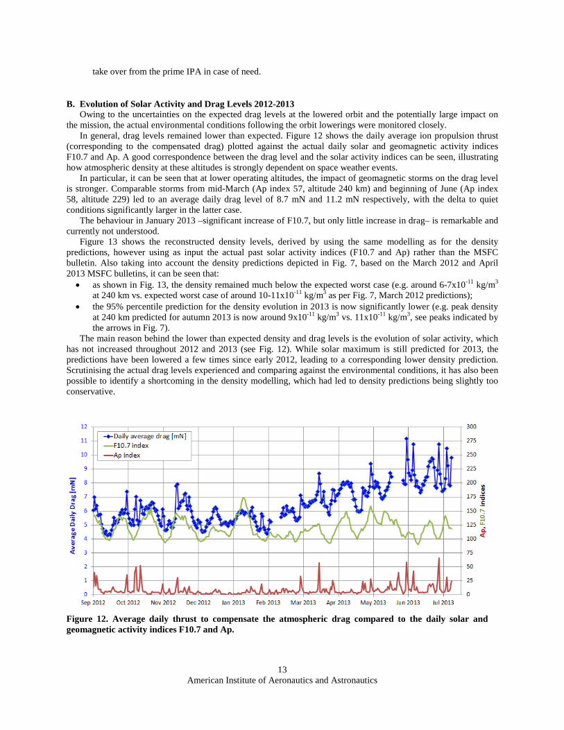
B. Evolution of Solar Activity and Drag Levels 2012-2013 Owing to the uncertainties on the expected drag levels at the lowered orbit and the potentially large impact on
the mission, the actual environmental conditions following the orbit lowerings were monitored closely. In general, drag levels remained lower than expected. Figure 12 shows the daily average ion propulsion thrust
(corresponding to the compensated drag) plotted against the actual daily solar and geomagnetic activity indices F10.7 and Ap. A good correspondence between the drag level and the solar activity indices can be seen, illustrating how atmospheric density at these altitudes is strongly dependent on space weather events.
In particular, it can be seen that at lower operating altitudes, the impact of geomagnetic storms on the drag level is stronger. Comparable storms from mid-March (Ap index 57, altitude 240 km) and beginning of June (Ap index 58, altitude 229) led to an average daily drag level of 8.7 mN and 11.2 mN respectively, with the delta to quiet conditions significantly larger in the latter case.
The behaviour in January 2013 –significant increase of F10.7, but only little increase in drag– is remarkable and currently not understood.
Figure 13 shows the reconstructed density levels, derived by using the same modelling as for the density predictions, however using as input the actual past solar activity indices (F10.7 and Ap) rather than the MSFC bulletin. Also taking into account the density predictions depicted in Fig. 7, based on the March 2012 and April 2013 MSFC bulletins, it can be seen that: • as shown in Fig. 13, the density remained much below the expected worst case (e.g. around 6-7x10-11 kg/m3
at 240 km vs. expected worst case of around 10-11x10-11 kg/m3 as per Fig. 7, March 2012 predictions); • the 95% percentile prediction for the density evolution in 2013 is now significantly lower (e.g. peak density
at 240 km predicted for autumn 2013 is now around 9x10-11 kg/m3 vs. 11x10-11 kg/m3, see peaks indicated by the arrows in Fig. 7).
The main reason behind the lower than expected density and drag levels is the evolution of solar activity, which has not increased throughout 2012 and 2013 (see Fig. 12). While solar maximum is still predicted for 2013, the predictions have been lowered a few times since early 2012, leading to a corresponding lower density prediction. Scrutinising the actual drag levels experienced and comparing against the environmental conditions, it has also been possible to identify a shortcoming in the density modelling, which had led to density predictions being slightly too conservative.
Figure 12. Average daily thrust to compensate the atmospheric drag compared to the daily solar and geomagnetic activity indices F10.7 and Ap.
American Institute of Aeronautics and Astronautics
13

C. Spacecraft Performance
Performance of the S/C and the drag-free control in particular was excellent. An interruption of drag-free mode on 14th Jan due to a problem with the ion propulsion system (not linked to the lowered altitude) could be recovered rapidly: the adapted FOS setup allowed restarting the engine within 6 hours, with an altitude loss of only 250 m.
The following special events linked to the lowered orbit and the higher drag levels were encountered: • In presence of geomagnetic storms, spikes on the observed linear acceleration in the flight direction occur.
This phenomena started during the low orbit operations campaign with some isolated cases while flying at altitudes of 240 km and higher, and significantly increased in frequency as 229 km were reached. The spikes in the observed linear acceleration are caused by the DFACS not being able to fully compensate the drag in presence of a rapid variation (increase or decrease) of the density level. In these occasions the IPA thrust as commanded by the DFACS using a dedicated thrust-limiter algorithm is not changing fast enough, resulting in a spike on the observed linear acceleration, which should nominally remain close to zero in drag-free mode. Figure 14 shows the thrust the DFACS would require to maintain the spacecraft in drag free conditions (blue line), the thrust actually delivered by the IPA (green line) and the observed linear acceleration (red line) for one of such cases. The negative spike in the observed linear acceleration means that the current drag level is being under-compensated (to be drag-free would require more thrust from the IPA, but the latter does not increase fast enough) while the positive spike means that the DFACS is over-compensating the drag (IPA provided thrust does not decrease fast enough).
• Since the spacecraft is flying at 229 km, during strong solar and geomagnetic activity periods the IPA maximum deliverable thrust of 21 mN is sporadically hit. As the DFACS is not allowed to request a thrust higher than 21 mN to the IPA, the system is not able to fully compensate the atmospheric drag, hence resulting in a negative observed linear acceleration peak. Figure 15 is showing one such case that occurred on 1st June 2013.
• The three star trackers (STR) were providing spurious invalid measurements at the same time, signalling the detection of a big bright orbit in the field of view. Each anomaly occurred at high latitudes at the time of strong geomagnetic activity. The current hypothesis is that this short transient blinding is linked to aurora phenomena: during geomagnetic storms auroras can exceptionally reach beyond GOCE’s operating altitude, and short-lived auroral rays of light may be generated. The geometry would be compatible with this hypothesis, however it is difficult to prove.
Figure 13. Average daily thrust to compensate the atmospheric drag compared to the daily solar and geomagnetic activity indices F10.7 and Ap.
American Institute of Aeronautics and Astronautics
14

-1.2E-06
-1.0E-06
-8.0E-07
-6.0E-07
-4.0E-07
-2.0E-07
0.0E+00
2.0E-07
4.0E-07
6.0E-07
8.0E-07
0
5
10
15
20
25
DFAC
S O
bser
ved
Line
ar A
ccel
erat
ion
[m/s
2 ]
Ion
Prop
ulsi
on T
hrus
t [m
N]
DFACS required thrust
IPA delivered thrust
DFACS Observed linear acceleration
Figure 15. Ion propulsion demanded and delivered thrust [mN] plotted against the observed linear acceleration [m/s2] during a 16 minutes period of a strong geomagnetic storm, with IPA reaching the maximum deliverable thrust of 21 mN.
-8.0E-07
-6.0E-07
-4.0E-07
-2.0E-07
0.0E+00
2.0E-07
4.0E-07
6.0E-07
8.0E-07
1.0E-06
1.2E-06
1.4E-06
0
2
4
6
8
10
12
14
DFAC
S O
bser
ved
Line
ar A
ccel
erat
ion
[m/s
2 ]
Ion
Prop
ulsi
on T
hrus
t [m
N]
DFACS required thrust
IPA delivered thrust
DFACS Observed linear acceleration
Figure 14. Ion propulsion demanded and delivered thrust [mN] plotted against the observed linear acceleration [m/s2] during a 3 minutes period of a geomagnetic storm with rapid changes of atmospheric density.
American Institute of Aeronautics and Astronautics
15

V. Conclusion and Outlook Following the very successful completion of GOCE’s routine mission at 259.6 km altitude, ESA has
implemented the so-called low orbit operations campaign, which entailed a further lowering of the orbit down to an exceptionally low altitude of 229 km, with the aim to tremendously improve the scientific return of GOCE prior to its end of life.
Lowering the orbit of GOCE beyond what had originally been foreseen proved to be a challenge. A scenario to decide on the minimum altitude feasible had to be devised. A range of measures on ground segment side were put in place to shorten reaction times and guarantee S/C safety at the lowered altitude. The spacecraft performance –in particular for the drag-free control system– had to be re-evaluated thoroughly for the expected high drag environment. The environmental conditions and the solar activity levels were closely monitored during the decay, allowing to select as a target the lowest possible altitude compatible with safe spacecraft operations.
The performance of both spacecraft and ground segment was excellent during the execution of the orbit lowering campaign down to 229 km. In particular the drag-free control system proved to work exceptionally well also at an extremely low altitude of 229 km, where the effects of geomagnetic storms on the space environment are pushing the ion engine to its limits in terms of maximum deliverable thrust.
The consumables are expected to run out in Q4/2013, after which the orbit will start decaying rapidly. Within a few weeks the S/C will re-enter, bringing an extremely successful mission to its end.
Appendix A Acronym List
ASH Accelerometer Sensor Head CESS Coarse Earth Sun Sensor CPM Coarse Pointing Mode DFACS Drag Free Attitude and Orbit Control System DFM Drag-free Mode DSS Digital Sun Sensor ECPM Extended Coarse Pointing Mode EGG Electrostatic Gravity Gradiometer FCT Flight Control Team FDIR Failure Detection, Isolation and Recovery FEEU Front End Electronics Unit FOP Flight Operations Plan FOS Flight Operations Segment FPM Fine Pointing Mode GAIEU Gradiometer Accelerometer Interface Electronic Unit GCA Gradiometer Calibration Assembly GOCE Gravity and Steady-state Ocean Circulation Explorer GPS Global Positioning System HPF High-level Processing Facility ILRS International Laser Ranging Service IPA Ion Propulsion Assembly KSAT Kongsberg Satellite Services AS LEOP Launch and Early Orbit Phase LORF Local Orbit Reference Frame MBW Measurement Bandwidth MCS Mission Control System MGM Magnetometer MTR Magnetic Torquer
American Institute of Aeronautics and Astronautics
16

PDGS Payload Data Ground Segment POD Precise Orbit Determination S/C Spacecraft SSTI Satellite-to-Satellite Tracking Instrument STR Star Tracker TCEU Thermal Control Electronic Unit
References 1Drinkwater, M.R., Floberghagen R., Haagmans R., Muzi D., and Popescu A., “GOCE: ESA's first Earth Explorer Core
mission,” Earth Gravity Field from Space - from Sensors to Earth Sciences, edited by G.B. Beutler, M.R. Drinkwater, R. Rummel, and R. von Steiger, Space Sciences Series of ISSI, Vol. 18, Kluwer Academic Publishers, Dordrecht, Netherlands, 2003, pp. 419-432.
2Drinkwater, M.R., Haagmans, R., Muzi, D., Popescu, A., Floberghagen, R., Kern, M., and Fehringer, M., “The GOCE Gravity Mission: ESA’s First Core Earth Explorer,” 3rd International GOCE User Workshop, ESA SP-627, ESA, Frascati, Italy, 2007.
3Steiger, C., Piñeiro, J., Emanuelli, P.P., “Operating GOCE, the European Space Agency’s Low-flying Gravity Mission,” SpaceOps 2010, Huntsville, USA.
4Steiger, C., Da Costa, A., Floberghagen, R., Fehringer, M., Emanuelli, P.P., “Weathering the Storm – GOCE Flight Operations in 2010”, 4th International GOCE User Workshop, ESA SP-696, Munich, Germany, 2011.
5Romanazzo, M., Steiger, C., Sechi, G., Saponara, M., Rezazad, M., Piris Niño, A., Da Costa, A., Fehringer, M., Floberghagen, R., André, G., Emanuelli, P.P., “In-orbit Experience with the Drag-Free Attitude and Orbit Control system of ESA’s Gravity Mission GOCE”, 8th International ESA Conference on Guidance, Navigation & Control Systems, Karlovy Vary, Czech Republic, 2011.
6Floberghagen, R., Fehringer, M., Lamarre, D., Muzi, D., Frommknecht, B., Steiger, C., Piñeiro, J., Da Costa, A., “Mission design, operation and exploitation of the gravity field and steady-state ocean circulation explorer mission”, Journal of Geodesy, Vol. 85, No. 11, 2011, pp. 749-758.
7Steiger, C., Da Costa, A., Emanuelli, P.P., Floberghagen, R., Fehringer, M., “Evolution of Flight Operations for ESA’s Gravity Mission GOCE,” SpaceOps 2012, Stockholm, Sweden.
8Allasio, A. Anselmi, A., Catastini, G., Cesare, S., Dumontel, M., Saponara, M., Sechi, G., Tramutola, A., Vinai, B., “GOCE mission: design phases and in-flight experiences”, AAS-10-081, 33rd Annual AAS Guidance and Control Conference, AAS-10-081, Breckenridge, USA, 2010.
9Sechi, G., Buonocore, M., Cometto, F., Saponara, M., Tramutola, A., Vinai, B., Andrè, G., Fehringer, M., “In-Flight Results from the Drag-Free and Attitude Control of GOCE Satellite”, 18th International Federation of Automatic Control (IFAC) world congress, Milan, Italy, 2011.
American Institute of Aeronautics and Astronautics
17
Copyright © 2022 FDOKUMEN