
Study of Ultrawide-Band Transmission in the Extremely High ...
10
IEEE TRANSACTIONS ON ANTENNAS AND PROPAGATION, VOL. 52, NO. 11, NOVEMBER 2004 2833 Study of Ultrawide-Band Transmission in the Extremely High Frequency (EHF) Band Yosef Pinhasi, Asher Yahalom, Oren Harpaz, and Guy Vilner Abstract—The growing demand for broad-band wireless com- munication links and the lack of wide frequency bands within the conventional spectrum, causes us to seek bandwidth in the higher microwave and millimeter-wave spectrum at extremely high frequencies (EHF) above 30 GHz. One of the principal challenges in realizing modern wireless communication links in the EHF band are phenomena occuring during electromagnetic wave propagation through the atmosphere. A space-frequency ap- proach for analyzing wireless communication channels operating in the EHF band is presented. Propagation of the electromagnetic radiation is studied in the frequency domain, enabling considera- tion of ultrawide-band modulated signals. The theory is employed for the analysis of a communication channel operating at EHF which utilizes pulse amplitude modulated signals. The atmo- spheric absorptive and dispersive effects on pulse propagation delay, pulse width and distortion are discussed. The theory and model are demonstrated in a study of ultrashort-pulse trans- mission at 60 GHz. Index Terms—Atmospheric attention, millimeter wave propaga- tion, ultrashort pulses, ultrawide-band transmission. I. INTRODUCTION T HE growing demand for broad-band wireless communi- cation links and the deficiency of wide frequency bands within the conventional spectrum, require utilization of higher microwave and millimeter-wave spectrum at the extremely high frequencies (EHF) above 30 GHz. In addition to the fact that the EHF band (30–300 GHz) covers a wide range, which is rela- tively free of spectrum users, it offers many advantages for wire- less communication and RADAR systems as follows: • broad bandwidths for high data rate information transfer; • high directivity and spatial resolution; • low transmission power (due to high antenna gain); • low probability of interference/interception (due to narrow antenna beamwidths); • small antenna and equipment size; • no multipath fadings (although fading can be caused by atmospheric conditions). Among the practical advantages of using the EHF region for satellite communications systems is the ability to employ Manuscript received July 27, 2003; revised February 13, 2004. This work was supported by the Israeli Software Radio Consortium, supported by the MAGNET program of the State of Israel Ministry of Industry and Commerce. Y. Pinhasi, A. Yahalom, and O. Harpaz are with the Department of Electrical and Electronic Engineering, The College of Judea and Samaria, Ariel 44837, Israel (e-mail: [email protected]). G. Vilner was with the Department of Electrical and Electronic Engineering, The College of Judea and Samaria, Ariel 44837, Israel. He is now a private contractor. Digital Object Identifier 10.1109/TAP.2004.835121 smaller transmitting and receiving antennas. This allows the use of a smaller satellite and a lighter launch vehicle. Some of the principal challenges in realizing modern wireless communication links at the EHF band are the effects emerging when the electromagnetic radiation propagates through the atmosphere. Fig. 1 is a schematic illustration of a wireless communication line-of-sight (LOS) link, where the distance between the transmitter and receiver sites is . At frequencies below the EHF band, the ratio between the received power and the transmitted power in line-of-sight (LOS) radio links, operating at a frequency , is given by the well-known Friss transmission (“link budget”) formula [1], [2] (1) where and are the transmitting and receiving antenna gains respectively, and m/s is the speed of light. The above formula describes the “free-space loss” due to diffraction of the transmitted radiation without considering atmospheric at- tenuation due to absorption and scattering and ignores multipath effects along the path of propagation. When millimeter-wave radiation passes through the atmos- phere, it suffers from selective molecular absorption [3]–[8]. Several empirical and analytical models were suggested for es- timating the millimeter and infrared wave transmission of the atmospheric medium. The transmission characteristics of the at- mosphere at the EHF band, as shown in Fig. 3 was calculated with the millimeter propagation model (MPM), developed by Liebe [9], [10]. Curves are drawn for several values of rela- tive-humidity (RH), assuming clear sky and no rain. Inspection of Fig. 3(a) reveals absorption peaks at 22 and 183 GHz, where resonance absorption of water (H O) occurs, as well as absorp- tion peaks at 60 and 119 GHz, due to absorption resonances of oxygen (O ). Between these frequencies, minimum attenuation is obtained at 35 (Ka band), 94 (W band), 130, and 220 GHz, which are known as atmospheric transmission “windows” [6]. The transmission characteristics are determined by weather conditions such as temperature, pressure and humidity. The ab- sorption is proportional to air density, and thus reduces with height. Attenuation due to fog, haze, clouds, rain and snow is one of the dominant causes of fading in wireless communication links operating in the EHF band [11], [12]. Raindrops and dust scatter millimeter wave radiation, resulting in amplitude fluctu- ations and phase randomness in the received signal. This further degrades the availability and performance of the communication links. Sufficient fade margins are essential for a reliable system. The inhomogeneous transmission in a band of frequencies causes absorptive and dispersive effects in the amplitude and in phase of wide-band signals transmitted in the EHF band. 0018-926X/04$20.00 © 2004 IEEE
-
Upload
khangminh22 -
Category
Documents
-
view
1 -
download
0
Transcript of Study of Ultrawide-Band Transmission in the Extremely High ...

IEEE TRANSACTIONS ON ANTENNAS AND PROPAGATION, VOL. 52, NO. 11, NOVEMBER 2004 2833
Study of Ultrawide-Band Transmission in theExtremely High Frequency (EHF) Band
Yosef Pinhasi, Asher Yahalom, Oren Harpaz, and Guy Vilner
Abstract—The growing demand for broad-band wireless com-munication links and the lack of wide frequency bands withinthe conventional spectrum, causes us to seek bandwidth in thehigher microwave and millimeter-wave spectrum at extremelyhigh frequencies (EHF) above 30 GHz. One of the principalchallenges in realizing modern wireless communication links inthe EHF band are phenomena occuring during electromagneticwave propagation through the atmosphere. A space-frequency ap-proach for analyzing wireless communication channels operatingin the EHF band is presented. Propagation of the electromagneticradiation is studied in the frequency domain, enabling considera-tion of ultrawide-band modulated signals. The theory is employedfor the analysis of a communication channel operating at EHFwhich utilizes pulse amplitude modulated signals. The atmo-spheric absorptive and dispersive effects on pulse propagationdelay, pulse width and distortion are discussed. The theory andmodel are demonstrated in a study of ultrashort-pulse trans-mission at 60 GHz.
Index Terms—Atmospheric attention, millimeter wave propaga-tion, ultrashort pulses, ultrawide-band transmission.
I. INTRODUCTION
THE growing demand for broad-band wireless communi-cation links and the deficiency of wide frequency bands
within the conventional spectrum, require utilization of highermicrowave and millimeter-wave spectrum at the extremely highfrequencies (EHF) above 30 GHz. In addition to the fact that theEHF band (30–300 GHz) covers a wide range, which is rela-tively free of spectrum users, it offers many advantages for wire-less communication and RADAR systems as follows:
• broad bandwidths for high data rate information transfer;• high directivity and spatial resolution;• low transmission power (due to high antenna gain);• low probability of interference/interception (due to narrow
antenna beamwidths);• small antenna and equipment size;• no multipath fadings (although fading can be caused by
atmospheric conditions).Among the practical advantages of using the EHF region
for satellite communications systems is the ability to employ
Manuscript received July 27, 2003; revised February 13, 2004. This workwas supported by the Israeli Software Radio Consortium, supported by theMAGNET program of the State of Israel Ministry of Industry and Commerce.
Y. Pinhasi, A. Yahalom, and O. Harpaz are with the Department of Electricaland Electronic Engineering, The College of Judea and Samaria, Ariel 44837,Israel (e-mail: [email protected]).
G. Vilner was with the Department of Electrical and Electronic Engineering,The College of Judea and Samaria, Ariel 44837, Israel. He is now a privatecontractor.
Digital Object Identifier 10.1109/TAP.2004.835121
smaller transmitting and receiving antennas. This allows theuse of a smaller satellite and a lighter launch vehicle.
Some of the principal challenges in realizing modern wirelesscommunication links at the EHF band are the effects emergingwhen the electromagnetic radiation propagates through theatmosphere. Fig. 1 is a schematic illustration of a wirelesscommunication line-of-sight (LOS) link, where the distancebetween the transmitter and receiver sites is .
At frequencies below the EHF band, the ratio between thereceived power and the transmitted power in line-of-sight(LOS) radio links, operating at a frequency , is given by thewell-known Friss transmission (“link budget”) formula [1], [2]
(1)
where and are the transmitting and receiving antennagains respectively, and m/s is the speed of light. Theabove formula describes the “free-space loss” due to diffractionof the transmitted radiation without considering atmospheric at-tenuation due to absorption and scattering and ignores multipatheffects along the path of propagation.
When millimeter-wave radiation passes through the atmos-phere, it suffers from selective molecular absorption [3]–[8].Several empirical and analytical models were suggested for es-timating the millimeter and infrared wave transmission of theatmospheric medium. The transmission characteristics of the at-mosphere at the EHF band, as shown in Fig. 3 was calculatedwith the millimeter propagation model (MPM), developed byLiebe [9], [10]. Curves are drawn for several values of rela-tive-humidity (RH), assuming clear sky and no rain. Inspectionof Fig. 3(a) reveals absorption peaks at 22 and 183 GHz, whereresonance absorption of water (H O) occurs, as well as absorp-tion peaks at 60 and 119 GHz, due to absorption resonances ofoxygen (O ). Between these frequencies, minimum attenuationis obtained at 35 (Ka band), 94 (W band), 130, and 220 GHz,which are known as atmospheric transmission “windows” [6].
The transmission characteristics are determined by weatherconditions such as temperature, pressure and humidity. The ab-sorption is proportional to air density, and thus reduces withheight. Attenuation due to fog, haze, clouds, rain and snow isone of the dominant causes of fading in wireless communicationlinks operating in the EHF band [11], [12]. Raindrops and dustscatter millimeter wave radiation, resulting in amplitude fluctu-ations and phase randomness in the received signal. This furtherdegrades the availability and performance of the communicationlinks. Sufficient fade margins are essential for a reliable system.
The inhomogeneous transmission in a band of frequenciescauses absorptive and dispersive effects in the amplitude andin phase of wide-band signals transmitted in the EHF band.
0018-926X/04$20.00 © 2004 IEEE

2834 IEEE TRANSACTIONS ON ANTENNAS AND PROPAGATION, VOL. 52, NO. 11, NOVEMBER 2004
Fig. 1. Wireless line-of-sight communication link.
Fig. 2. Linear system representing propagation of electromagnetic waves in a medium.
The frequency response of the atmosphere plays a significantrole as the data rate of a wireless digital radio channel is in-creased. The resulting amplitude and phase distortion leads tointer-symbol interference, and thus to an increase in the bit errorrate (BER). These effects should be taken into account in the de-sign of broad-band communication systems, including carefulconsideration of appropriate modulation, equalization and mul-tiplexing techniques.
Several theoretical papers dealt with the problem of distortionoccurring when a short pulse is propagating in absorptive anddispersive media, including gases and plasmas [13]–[19]. Theyalso studied the delay and pulse shape evolution along the pathof propagation. Gibbins [18] extended earlier investigations[14], [16] and examined distortions of short Gaussian pulses,modulating millimeter waves and propagating in the atmos-phere. An approximation of the wave propagation factor wasused to derive analytical expressions for the pulse shape. Con-ditions for pulse broadening and compression were identified.
Approximate formulations are restricted to an initialGaussian pulse and result in errors in the calculation of itsshape evolution during propagation. These errors increase asthe initial pulse duration is shortened. Moreover, the validityof the analytical expression is limited, and does not permitconsideration of ultrashort pulses, which violate the conditionsfor existence of a solution. In this paper, we develop a generalspace-frequency approach for studying wireless communica-tion channels operating in the EHF band. The theory is usedto compare between analytical and numerical models. Theconstraints of the derived analytical expressions are discussed,pointing out conditions of validity. The MPM model [9], [10]is used in the numerical model for calculation of atmosphericcharacteristics in the frequency domain. The resulting propaga-tion factor is calculated numerically, enabling one to deal withultrawide-band arbitrary signals.
The theory was used to study the effects of the atmosphericmedium on a radio link, shown in Fig. 1. The data signal, repre-sented by a complex envelope , modulates a carrier wave
at frequency . The resultant signal is transmitted and propa-gates to the receiver site through the atmosphere along a line-of-sight path. The demodulated in-phase and quadrature
signals, retrieved at the receive outputs, are examinedallowing evaluation of the performance of a high data rate dig-ital wireless channel operating at millimeter wavelengths.
The application of the model is demonstrated on a wirelessdata link operating in the 60 GHz band. The unused frequencyspace and the high attenuation due to oxygen absorption( 15 dB/Km) [20]–[22] make this frequency range naturallyfitting for local broad-band digital networks with small reusedistances [23]. The effects predicted by the analytical deriva-tion are inspected in the numerical simulations, including theevolution of pulse distortion along the path of propagationin the atmospheric medium. The numerical model enablesconsideration of further ultrashort pulses, enduring very fewcarrier periods; such situations cannot be treated with the aid ofanalytical approximated derivations.
II. MILLIMETER WAVE PROPAGATION IN THE ATMOSPHERE
The time dependent field represents an electromagneticwave propagating in a medium. The Fourier transform of thefield is
(2)
Propagation of electromagnetic waves in a medium can beviewed as transformation through a system (see Fig. 2).
In the far field, transmission of a wave, radiated from a lo-calized (point) isotropic source and propagating in a (homoge-neous) medium is characterized in the frequency domain by thetransfer function, derived in Appendix A
(3)

PINHASI et al.: STUDY OF ULTRAWIDE-BAND TRANSMISSION IN EHF BAND 2835
Fig. 3. Millimeter wave (a) attenuation coefficient 20 log(e) � �(f) in [dB/Km] and (b) wavenumber increment ��(f ) = (2�f=c) � N (f) in [rad/Km] forvarious values of relative humidity (RH).
Here, is a frequency dependent propagationfactor, where and are the permittvity and the permeability ofthe medium, respectively. The transfer function describesthe frequency response of the medium. Its inverse Fourier trans-formation corresponds to the temporal impulse response .In a dielectric medium the permeability is equal to that of thevacuum and the permittivity is given by
. If the medium introduces losses and dispersion, the rela-tive dielectric constant is a complex, frequency depen-dent function, for which its real and imaginary parts satisfy theKramers-Kronig relations [24], [25]. The resulting index of re-fraction can be presented by
(4)
where is the complex refractivityof the molecules composing the air [11]. The propagation factorcan be written in terms of the index of refraction
(5)
Substituting expressions (4) and (5) in (3), assuming horizontalpropagation in an homogeneous medium, results in the transferfunction
(6)
where is the attenua-tion coefficient andis the wavenumber of the propagating wave, shown in Fig. 3.
The power transfer function along the propagation path isgiven by
(7)
and is shown in Fig. 4 for frequencies of 35 and 94 GHz, whereminimum attenuation (“transmission window”) is obtained, aswell for 60 and 119 GHz where maximum absorption by oxygenmolecules occurs.
III. TRANSMISSION OF BROAD-BAND MODULATED SIGNAL
Assume that a carrier wave at is modulated by a wide-bandsignal
(8)
as shown in Fig. 1. Here, is acomplex envelope, representing the base-band signal, where
and are thein-phase and the quadrature information waveforms, respec-tively. The Fourier transform of the transmitted field is
(9)

2836 IEEE TRANSACTIONS ON ANTENNAS AND PROPAGATION, VOL. 52, NO. 11, NOVEMBER 2004
Fig. 4. Power transfer at the “transmission window” frequencies of 35 and94 GHz and at the oxygen absorption frequencies of 60 and 119 GHz.
where is the Fourier transform of the complex envelope. After propagating along a path with a distance , the
field is
(10)
Since the transfer function is the Fourier transform of areal function . The inverse Fourier transfor-mation of (10), results in a received field given in the time do-main by
(11)
where the complex envelope of the signal obtained at the re-ceiver cite is given by
(12)
The formalism developed above is utilized in the followingfor analytical derivation and numerical calculations of the de-modulated signal at the receiver site. The flow chart in Fig. 5summarizes the procedure carried out for solving (12). A base-band digital signal , fed to the modulator at the trans-mitter site modulates a carrier at . The MPM model [10]–[12]is called for to calculate the complex refractivity of the atmos-phere, as required in the transfer function (6). Finally, the de-modulated complex signal and its related quadraturecomponents and obtained at the receiver outputare found, employing an algorithm of fast Fourier transforma-tion (FFT) for solving (12).
IV. ULTRAWIDE-BAND PULSE MODULATION
Assume that the transmitted waveform is a carrier modulatedby a Gaussian envelope
(13)
Fig. 5. Procedure for calculation of demodulated quadrature signals receivedin a wireless communication channel.
Fig. 6. Normalized Gaussian lineshape.
characterized by a standard deviation . Fourier transforma-tion of the pulse results in a Gaussian line-shape in the frequencydomain
(14)
shown in Fig. 6. The corresponding standard deviation fre-quency bandwidth is . The full-widthhalf-maximum (FWHM) is the dB bandwidth and is equalto .
In order to calculate the pulse shape after propagationalong a horizontal path in the atmospheric medium, we substi-tute the Fourier transform (14) into expression (12). Analyticalresult can be found if the complex propagation factor (5) is

PINHASI et al.: STUDY OF ULTRAWIDE-BAND TRANSMISSION IN EHF BAND 2837
Fig. 7. Absorption line of the Oxygen at 60 GHz (a) attenuation coefficient�(f) = (2�f=c)�N (f) and (b) wavenumber increment��(f ) = (2�f=c)�N (f).
TABLE ICOMPLEX PROPAGATION FACTORS AT THE 60 GHz BAND
approximated in the vicinity of the carrier frequency , by asecond-order Taylor expansion [14]–[16]
(15)
where .The second-order approximation given in (15) can be used ifthe standard deviation of the Gaussian pulse satisfies
resulting in a complex envelope
(16)
where
The expression obtained at (16) is valid if
(17)
This condition is always satisfied if . However, at fre-quencies for which the attenuation curve is convex(in the vicinity of the absorption lines) the analytical results arevalid only for . Another interpreta-tion of this result is that for a given initial pulse width , thedistance should not exceed in order for(16) to be valid.
The magnitude (absolute value) of the complex envelopegiven by (16), has a Gaussian shape
(18)

2838 IEEE TRANSACTIONS ON ANTENNAS AND PROPAGATION, VOL. 52, NO. 11, NOVEMBER 2004
Fig. 8. Graphs of (a) group delay and (b) standard deviation versus frequency after a pulse propagation distance of d = 1 Km.
with a temporal delay
(19)
and a standard deviation given by
(20)
These results, which can be obtained from the solu-tions derived in [14] and [16], show that in the frame-work of the approximation (15), a Gaussian magnitude
is preserved while propa-gating in the medium (although its width changes) and thus canbe retrieved by the receiver.
Since the pulse cannot propagate above a velocity of the speedof light the time delay, given by (19) is always .This fact points out that the medium response should fulfill
at any frequency. For a short distance(or a wide pulse), the time delay can be approximated by
. This becomes the exact solution at attenuation peaks,where . When , the denominator of (19) may be-come arbitrary small, (however should be kept positive in orderto satisfy the validity condition (17)). In that case the time delayis approximately(where must be ), resulting in and arbitrary long delayin the pulse arrival at a distance d.
Examination of (20) reveals that when the pulsealways widens along the path of propagation. However,for (e.g., in the vicinity of absorption frequen-cies), the pulse may become narrower while propagating inthe atmospheric medium. Pulse compression occurs when
. In both cases min-imum pulse width is obtained forresulting in .
For long propagation distances, the time delay approachesand the standard deviation.
V. NUMERICAL RESULTS—PROPAGATION AT 60 GHz
An interesting application of the described approach is theanalysis of transmission of ultrashort-pulses in the 60 GHz band.The high atmospheric attenuation and dispersive effects, causedby the absorption of the oxygen molecules at this frequencyregion [23]–[25], are expressed as evident distortions on thepulse delay, duration and shape. The complex propagation factor
in the 60 GHz band is shown in Fig. 7as a solid line. The dashed lines describe curves of polyno-mials, which resulted from second-order Taylor expansions at60.5 GHz, where the absorption peaks and at 56.5 and63 GHz, where .
Table I summarizes the values of the complex propagationfactor at these three frequencies, including their first andsecond derivatives. These numbers are used in the analytical
PINHASI et al.: STUDY OF ULTRAWIDE-BAND TRANSMISSION IN EHF BAND 2839
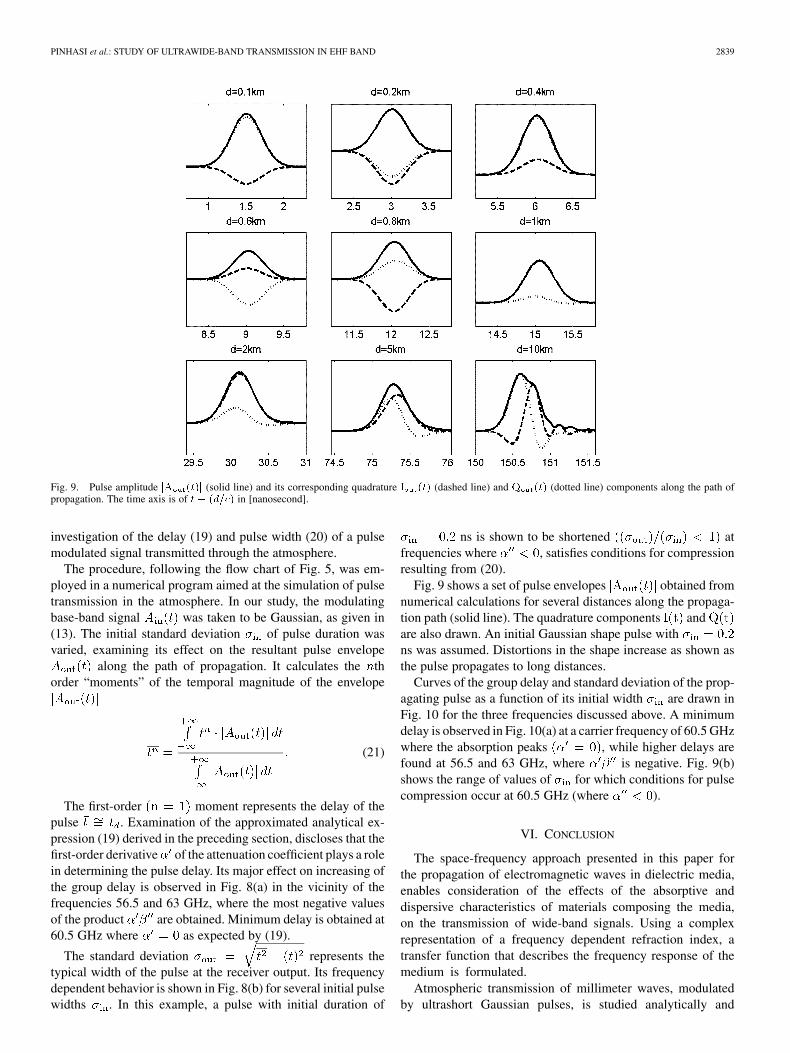
Fig. 9. Pulse amplitude jA (t)j (solid line) and its corresponding quadrature I (t) (dashed line) and Q (t) (dotted line) components along the path ofpropagation. The time axis is of t � (d=c) in [nanosecond].
investigation of the delay (19) and pulse width (20) of a pulsemodulated signal transmitted through the atmosphere.
The procedure, following the flow chart of Fig. 5, was em-ployed in a numerical program aimed at the simulation of pulsetransmission in the atmosphere. In our study, the modulatingbase-band signal was taken to be Gaussian, as given in(13). The initial standard deviation of pulse duration wasvaried, examining its effect on the resultant pulse envelope
along the path of propagation. It calculates the thorder “moments” of the temporal magnitude of the envelope
(21)
The first-order moment represents the delay of thepulse . Examination of the approximated analytical ex-pression (19) derived in the preceding section, discloses that thefirst-order derivative of the attenuation coefficient plays a rolein determining the pulse delay. Its major effect on increasing ofthe group delay is observed in Fig. 8(a) in the vicinity of thefrequencies 56.5 and 63 GHz, where the most negative valuesof the product are obtained. Minimum delay is obtained at60.5 GHz where as expected by (19).
The standard deviation represents thetypical width of the pulse at the receiver output. Its frequencydependent behavior is shown in Fig. 8(b) for several initial pulsewidths . In this example, a pulse with initial duration of
ns is shown to be shortened atfrequencies where , satisfies conditions for compressionresulting from (20).
Fig. 9 shows a set of pulse envelopes obtained fromnumerical calculations for several distances along the propaga-tion path (solid line). The quadrature components andare also drawn. An initial Gaussian shape pulse withns was assumed. Distortions in the shape increase as shown asthe pulse propagates to long distances.
Curves of the group delay and standard deviation of the prop-agating pulse as a function of its initial width are drawn inFig. 10 for the three frequencies discussed above. A minimumdelay is observed in Fig. 10(a) at a carrier frequency of 60.5 GHzwhere the absorption peaks , while higher delays arefound at 56.5 and 63 GHz, where is negative. Fig. 9(b)shows the range of values of for which conditions for pulsecompression occur at 60.5 GHz (where ).
VI. CONCLUSION
The space-frequency approach presented in this paper forthe propagation of electromagnetic waves in dielectric media,enables consideration of the effects of the absorptive anddispersive characteristics of materials composing the media,on the transmission of wide-band signals. Using a complexrepresentation of a frequency dependent refraction index, atransfer function that describes the frequency response of themedium is formulated.
Atmospheric transmission of millimeter waves, modulatedby ultrashort Gaussian pulses, is studied analytically and

2840 IEEE TRANSACTIONS ON ANTENNAS AND PROPAGATION, VOL. 52, NO. 11, NOVEMBER 2004
Fig. 10. Graphs of (a) group delay and (b) standard deviation as a function initial pulse duration, after a propagation distance of d = 1 Km.
numerically in the frequency domain revealing spectral ef-fects on pulse propagation delay, width and distortions. Usingsecond-order expansion of the propagation factors leads tothe derivation of approximated analytical expressions for thedelay and width as a function of distance and carrier frequency.Conditions under which pulse compression or expansion occurswere identified. The analytical solution is found to be limitedin describing wide-band communication links where ultrashortpulses are involved. In such links the numerical model use isrequired.
The effects, predicted by the analytical solution, were com-pared to the results obtained from a numerical simulation, aimedat the calculation of pulse evolution while propagating in theatmospheric media. By studying propagation of a pulse in theatmosphere, characterized by the millimeter-wave propagationmodel (MPM), it was shown that even in a medium of atmo-spheric air some of the effects that we predict are pronouncedespecially for carrier frequencies in the vicinity of the 60 GHz,where high absorption of oxygen molecules occurs.
APPENDIX A
This appendix is aimed at derivation of the transfer functiongiven in (3). In an homogeneous dielectric medium, the electric
and magnetic fields, excited by current
and charge densities, follow the macroscopic Maxwellequations, consisting of Faraday law
(A.1)
Ampere law
(A.2)
and Gauss laws
(A.3)
Here, and are the electric and magneticflux densities respectively. In a homogeneous isotropicdielctric medium, their Fourier transforms can be writtenas and , where
is the frequency dependent permittvity and is thepermeability of the medium. Substituting the last relations inthe Fourier transform of the Maxwell equations results in aspace-frequency Helmholtz equation
(A.4)

PINHASI et al.: STUDY OF ULTRAWIDE-BAND TRANSMISSION IN EHF BAND 2841
where . Defining a driving term
(A.5)
we obtain the equation in the form
(A.6)
The Green function is the result of a point-source exci-tation
(A.7)
This equation can be written in terms of as
(A.8)
Since the Green function must be spherically symmetric, the(A.9) can be written in the form
(A.9)
For one obtains
(A.10)
which has the trivial solution
(A.11)
For the equation takes the form
(A.12)
with the solution
(A.13)
Adjusting the two solutions (A.12) and (A.14) yields
(A.14)For a radiating source we expect only an outgoing wave. Hence,
and the solution for the radiated field is given by
(A.15)
In the far field and the field can be approxi-mated by a spherical wave radiated from a localized source
(A.16)
If we measure the field at a far-field distancefrom the source and the field at a distance ,then dividing any component of the two fields results in
(A.17)
leading to the transfer function given in (3).
ACKNOWLEDGMENT
The authors acknowledge the help of The Samuel NeamanInstitute for Advanced Studies in Science and Technology. Theauthors also thank Eng. A. Eichenbaum for useful discussions.
REFERENCES
[1] H. T. Friss, “A note on a simple transmission formula,” in Proc. IRE,vol. 34, 1946, pp. 254–256.
[2] J. D. Kraus, Antennas. New York: McGraw-Hill, 1988.[3] R. K. Crane, “Propagation phenomena affecting satellite communication
systems operating in the centimeter and millimeter wavelength bands,”Proc. of the IEEE, vol. 59, no. 2, pp. 173–188, 1971.
[4] , “Fundamental limitations caused by RF propagation,” Proc. IEEE,vol. 69, no. 2, pp. 196–209, 1981.
[5] L. J. Ippolito, “Radio propagation for space communication systems,”Proc. IEEE, vol. 69, no. 6, pp. 697–727, 1981.
[6] H. J. Liebe, “Atmospheric EHF window transparencies near 35, 90, 140,and 220 GHz,” IEEE Trans. Antennas Propagat., vol. AP-31, no. 1, pp.127–135, 1983.
[7] R. A. Bohlander and R. W. McMillan, “Atmospheric effects on nearmillimeter wave propagation,” Proc. IEEE, vol. 73, no. 1, pp. 49–60,1985.
[8] N. C. Currie and C. E. Brown, Principles and Applications of Millimeter-Wave Radar. Norwood, MA: Artech House, 1987.
[9] H. J. Liebe, “An updated model for millimeter wave propagation in moistair,” Radio Sci., vol. 20, pp. 1069–1089, 1985.
[10] , “MPM—An atmospheric millimeter-wave propagation model,”Int. J. Infrared and Millimeter Waves, vol. 10, no. 6, pp. 631–650, 1989.
[11] H. J. Liebe, T. Manabe, and G. A. Hufford, “Millimeter-wave attenua-tion and delay rates due to fog/cloud conditions,” IEEE Trans. AntennasPropagat., vol. AP-37, pp. 1617–1623, Dec. 1989.
[12] H. J. Liebe, G. A. Hufford, and T. Manabe, “A model for the complexpermittivity of water at frequencies below 1 THz,” Int. J. Infrared andMillimeter Waves, vol. 12, no. 7, pp. 659–675, 1991.
[13] O. E. Delange, “Propagation studies at microwave frequencies by meansof very short pulses,” Bell Syst. Tech. J., vol. 31, pp. 91–103, 1952.
[14] M. P. Forrer, “Analysis of millimicrosecond RF pulse transmission,” inProc. IRE, vol. 46, 1958, pp. 1830–1835.
[15] L. E. Vogler, “Pulse distortion in resonant and nonresonant gases,” RadioSci., vol. 5, pp. 1169–1180, 1970.
[16] G. I. Terina, “On distortion of pulses in ionospheric plasma,” Radio Eng.Electron. Phys., vol. 12, pp. 109–113, 1967.

2842 IEEE TRANSACTIONS ON ANTENNAS AND PROPAGATION, VOL. 52, NO. 11, NOVEMBER 2004
[17] D. B. Trizna and T. A. Weber, “Brillouin revisited: Signal velocity defi-nition for pulse propagation in a medium with resonant anomalous dis-persion,” Radio Sci., vol. 17, pp. 1169–1180, 1982.
[18] C. J. Gibbins, “Propagation of very short pulses through the absorptiveand dispersive atmosphere,” Proc. Inst. Elect. Eng., vol. 137, no. 5, pp.304–310, 1990.
[19] A. Maitra, M. Dan, A. K. Sen, S. Bhattacharyya, and C. K. Sarkar, “Prop-agation of very short pulses at millimeter wavelengths through rain filledmedium,” Int. J. Infrared Millimeter Waves, vol. 14, no. 3, pp. 703–713,1993.
[20] J. H. van Vleck, “The absorption of microwaves by oxygen,” Phys. Rev.,vol. 71, pp. 413–424, 1947.
[21] P. W. Rosenkranz, “Shape of the 5 mm oxygen band in the atmosphere,”IEEE Trans. Antennas Propagat., vol. AP-23, pp. 498–506, 1975.
[22] H. J. Liebe, P. W. Rosenkranz, and G. A. Hufford, “Atmospheric 60GHz oxygen spectrum: New laboratory measurements and line parame-ters,” J. Quantitative Spectroscopy and Radiative Transfer, vol. 48, pp.629–643, 1992.
[23] F. Giannetti, M. Luise, and R. Reggiani, “Mobile and personal commu-nications in the 60 GHz band: A survey,” Wireless Personal Communi-cations, vol. 10, pp. 207–243, 1999.
[24] H. A. Kramers, “Some remarks on the theory of absorption and refrac-tion of x-rays,” Nature, vol. 117, p. 775, 1926.
[25] R. de L. Kronig, “On the theory of dispersion of x-rays,” J. Opt. Soc.Amer., vol. 12, pp. 547–557, 1926.
[26] A. Yariv, Quantum Electronics. New York: Wiley, 1988.
Yosef Pinhasi was born in Israel on May 3, 1961.He received the B.Sc., M.Sc., and Ph.D. degrees inelectrical engineering from Tel-Aviv University, Tel-Aviv, Israel, in 1983, 1989, and 1995, respectively.
From 1983 to 1989, he worked with the IsraeliMinistry of Defense as a Research and DevelopmentEngineer. Since 1990, he has been working in thefield of electromagnetic radiation, investigatingmechanisms of its generation in high power ra-diation sources and free-electron lasers (FELs).He developed a unified coupled-mode theory of
electromagnetic field excitation and propagation in the frequency domain,enabling study of wide-band interactions of electromagnetic waves in mediain the linear and nonlinear (saturation) operation regimes. Currently, he is aProfessor on the Faculty of Engineering at the College of Judea and Samaria,and the Head of the Department of Electrical and Electronic Engineering. Heinvestigates utilization of electromagnetic waves in a wide range of frequen-cies for various applications such as communications, remote sensing, andimaging. The space-frequency approach, which he developed, is employed tostudy propagation of wide-band signals in absorptive and dispersive media inbroad-band communication links, LANs, and wireless.
Asher Yahalom was born in Israel on November 15,1968. He received the B.Sc., M.Sc., and Ph.D. de-grees in mathematics and physics from the HebrewUniversity, Jerusalem, Israel, in 1990, 1991, and 1996respectively.
From 1994 to 1998, he was Head of the Magne-tostatic Team at Direx Medical System, working onthe development of a novel MRI machine, he thenbecame a Consultant in various mathematical andalgorithmic issues related to the development of the“gamma knife”—a radiation-based head surgery
system. In 1998, he joined the Israeli Free Electron Laser (FEL) Group,College of Judea and Samaria, Ariel, Israel, both as a Postdoctoral Fellow andas a Project Manager. Among his contributions to the project are theoreticalcontributions (finding Kramers–Kronig relations for FEL amplitude-phase, for-mulating a variational principle for FEL physics), technological contributions(working on two stage and multistage electron collectors, suggesting majorimprovement in the FEL Talbot effect radiation resonator which led to the firstpowerful lasing on April 9, 2003). Currently, he is a Senior Lecturer on theFaculty of Engineering, College of Judea and Samaria, where he is also theFounder and Academic Director of the FEL User Center. His research interestsinclude works in a wide range of scientific and technological subjects rangingform the foundations of quantum mechanics to molecular dynamic, fluiddynamics, electromagnetics, communications, signal processing and imaging.
Oren Harpaz was born in Israel on May 19, 1976.He received the degree in electrical engineering fromThe College of Judea and Samaria, Ariel, Israel,in 2002. He is currently working toward the M.Sc.degree at Tel-Aviv University, Tel-Aviv, Israel. Histhesis work is aimed at research of interactionsbetween high power microwave and dielectric mate-rials and study of the resulted heating in crystals.
Guy Vilner was born in Israel on October 24, 1977. He received the degree inelectrical engineering from The College of Judea and Samaria, Ariel, Israel, in2002.
He is currently working in his own company.