One Gun Phase Points: A Reassessment of the Late Side-Notched Projectile Point System in Alberta
Upload
independentCategory
view
0download
0
Progress In Electromagnetics Research, Vol. 123, 143–158, 2012
STUDY OF AN EXTREMELY WIDEBAND MONOPOLEANTENNA WITH TRIPLE BAND-NOTCHED CHARAC-TERISTICS
J. Liu1, 2, *, K. P. Esselle1, S. G. Hay2, and S. S. Zhong3
1Centre for Microwave and Wireless Applications, Electronic Engineer-ing, Macquarie University, Sydney, NSW 2109, Australia
2CSIRO, ICT Centre, P. O. Box 76, Epping Sydney, NSW 1710,Australia
3School of Communication and Information Engineering, ShanghaiUniversity, Shanghai 200072, China
Abstract—Three notched bands are generated, at selected frequen-cies, in an extremely wideband base antenna to support multiple com-munication systems while avoiding inference from other existing nar-rowband systems. The design of a fully printed extremely widebandantenna and creating triple band-notched functions are addressed inthis paper. Measurements demonstrate that the proposed printed baseantenna has an extremely wide 2 : 1 VSWR bandwidth from 0.72 GHz,to 25GHz with a ratio bandwidth of 34 : 1. The antenna has a simplestructure and can be fabricated at low cost for multi-band and wide-band wireless communication devices. Besides, this paper presents atechnique to form three notched bands within the operating frequencyrange of the base antenna. By introducing a half-wavelength U-shapeddefected ground structure (DGS) and a pair of quarter-wavelengthopen arc-shaped slots to the radiating patch, three notched bands arecreated to prevent interference from WLAN (2.4–2.484 GHz and 5.15–5.85GHz) systems and downlinks of X-band satellite communication(7.25–7.75GHz) systems.
Received 4 November 2011, Accepted 5 December 2011, Scheduled 18 December 2011* Corresponding author: Jianjun Liu ([email protected]).

144 Liu et al.
1. INTRODUCTION
The Federal Communication Commission’s (FCC) allocation of 3.1to 10.6 GHz for ultra-wideband (UWB) communication has createdinterest in antennas with ultra or extremely wide bandwidths. ForUWB systems, printed monopole antennas with various radiationpatch shapes are widely used due to their advantages of low cost,light weight and ease of fabricating and integrating with electronicdevices [1–9]. In order to support multiple communication servicesin a single device through UWB and other communication systems, asingle antenna that has the ability to operate in all these frequencybands is highly desirable. Printed antenna designs with enhancedbandwidths for multiple wireless systems have been proposed recently.For example, in [10], a printed elliptical monopole antenna witha hexagonal ground plane has been introduced to support UMTSand UWB systems. A microstrip-fed antenna with an L-shapedramification on the radiation patch has been presented in [11] forBluetooth and UWB systems. In our lab, a printed elliptical antennawith a tapered and modified feed was designed to support a numberof wireless communication frequency bands [12].
On the other hand, within the FCC-designated band for UWBsystems, there exist several relatively narrow frequency bands usedby other wireless systems such as IEEE 802.11b/g/n wireless local-area networks (WLAN) operating at 2.4–2.484GHz, IEEE 802.11a/noperating at 5.15–5.35 GHz and 5.725–5.825GHz and downlink of X-band satellite communication systems operating at 7.25–7.75 GHz.To avoid interference between UWB systems and these narrowbandwireless communication systems, separate bandnotch filters can beadded to the system. However, these additional filters will increasethe volume, weight and complexity of the system. Recently, manywideband antennas with integrated band-notched functions have beendeveloped, to avoid the need for external bandnotch filters. It hasbeen achieved by embedding complementary resonant elements intothe main radiating element. For example, slots of various shapes madein a radiation patch can provide such a band-notched function [13–23].However, these slot layouts can provide only one notched bands, andhence their practical applications are limited. Recently, some designswith the characteristics of a dual notched band [24–33] and even atriple notched band are presented [34–36].
An extremely wideband antenna with three notched bands ispresented in this paper. It is organized as follows. Section 2describes the base antenna, which has an extremely wide bandwidth.The measured results indicate that the bandwidth of the base

Progress In Electromagnetics Research, Vol. 123, 2012 145
antenna ranges from 0.72 GHz to 25 GHz with a ratio bandwidthof 34 : 1. Hence, it can support many communication systemssuch as GSM (880–960 MHz), GPS (1.57–1.58 GHz),WCDMA (1.92–2.17GHz), UWB (3.1–10.6GHz) and MVDDS (12.2–12.7GHz). Theprinciple of its operation is also studied. Section 3 describes the tripleband-notched functions, which are realized on this extremely widebandprinted antenna. Three notched bands are achieved by introducinga half-wavelength U-shaped defected ground structure (DGS) and apair of quarter-wavelength open arc-shaped slots. The variation ofthe slots and DGS parameters on multiple band-notched functions arediscussed. The principles of the band-notched design are also presentedwith formulas in this paper.
(a)
(b) (c)
Figure 1. (a) The configuration of the base antenna. (b) The top sideof the fabricated base antenna. (c) The back side of the fabricated baseantenna.

146 Liu et al.
2. BASE ANTENNA DESIGN
The base antenna is composed of a printed monopole and a modifiedtrapezoid ground plane, illustrated in Figure 1(a). The groundplane and monopole are etched on the back and top surfaces ofa TACONIC TLX-0 substrate, respectively. Its thickness (h) is0.787mm, the relative permittivity (εr) 2.45 and the metal claddingthickness 0.01 mm. The monopole, with maximum length a and widthb, is fed by a tapered microstrip feeding line in the middle of theground plane. The ground plane is a part of the impedance matchingnetwork. The top rounded corners of the trapezoid ground plane reducethe sensitivity to fabrication tolerances and help to achieve a betterimpedance match. The radius of the rounded bends of the ground planeis denoted by R. The gap, t, between the patch and the trapezoidalground plane, plays a vital role in bandwidth performance. The widthof the central strip at the top end (Wtop) is 1.1mm, correspondingto a characteristic impedance of 75 Ω, and the width at the bottomend (Wbot) is 2.3mm, corresponding to a characteristic impedance of50Ω. The tapered feeding line gradually transforms the impedancefrom 50 to 75 Ω and provides better wideband performance than a
Table 1. Dimensions of the base antenna [mm].
Dmax Dmin H t Wtop
150 120 34 0.4 1.1a b L R Wbot
144 114 150 25 2.3
Figure 2. Measured and predicted VSWR of the base antenna.

Progress In Electromagnetics Research, Vol. 123, 2012 147
straight microstrip feed. Parametric analyses of this base antenna havebeen conducted by changing one parameter at a time while keepingthe others constant. Through proper selection of the parameters ofthe ground plane and radiation patch, a greatly enhanced impedancebandwidth can be achieved. The selected parameter values are listedin Table 1. The photograph of the fabricated antenna is shown inFigures 1(b) and (c).
The base antenna has been designed and optimised using CSTMicrowave Studio commercial software, and the measured VSWRresults have been obtained by using a Wiltron37369A vector networkanalyser (40 MHz–40GHz). The predicted 2 : 1 VSWR bandwidthis from 0.705 to 25 GHz, while the measured bandwidth covers a
(a) (b)
Figure 3. VSWR of the base antenna with different patch (a) widthsa and (b) lengths b.
Figure 4. VSWR of antennas with different gaps.

148 Liu et al.
E-plane H-plane
(a)
(b)
(c)

Progress In Electromagnetics Research, Vol. 123, 2012 149
(d)
(e)
Figure 5. Measured radiation patterns. (a) f = 1 GHz. (b)f = 5 GHz. (c) f = 10 GHz. (d) f = 15 GHz. (e) f = 20GHz.
frequency range from 0.72 to 25 GHz with a ratio bandwidth of 34 : 1(see Figure 2). A good agreement between the predicted and measuredresults can be observed. The low frequency limit of the VSWRbandwidth is determined by the total effective length of the antennacurrent path, which includes the radiation patch and the ground plane.Therefore, increasing the effective dimensions of the radiation patchand ground plane can decrease the low frequency limit. As shown inFigure 3, when the patch width a is increased from 80 to 144mm, thelower frequency limit decreases from 1.43GHz to 0.705GHz. The lowerfrequency limit is reduced from 0.84 GHz to 0.705GHz when the patchheight b is increased from 50mm to 144 mm. The higher frequency limitis associated with several parameters, including the gap between thepatch and the trapezoid ground plane and the microstrip to monopoleterminal layout. Figure 4 indicates that the impedance matching at

150 Liu et al.
high frequencies strongly depends on the gap t.The measured normalized far-field radiation patterns at 1, 5, 10,
15 and 20 GHz are shown in Figure 5. They indicate that this antennahas a nearly omni-directional radiation pattern at low frequencies inthe H-plane (e.g., at 1GHz). The E-plane radiation pattern showstwo nulls at 1 GHz, which is similar to that of a conventional dipoleantenna. The cross polarization on the E-plane stays at relativelylow levels over the whole operating frequency band. However, in theH-plane, it can be seen that the cross-polarization level rises withfrequency owing to the increasing horizontal component of surfacecurrents. Pattern ripples become more prominent at higher frequenciessince the antenna operates in higher order modes instead of the typicalmonopole mode.
3. CREATING TRIPLE NOTCHED BANDS
In this section, to avoid potential interference with 802.11a/b/g/nWLAN systems and downlink of X-band satellite communicationsystems, band notching is introduced to the base antenna described inSection 2. This is achieved by embedding a defected ground structure(DGS) and arc-shaped slots that resonate around notched bands. Theconfiguration of the antenna with triple notched bands is illustratedin Figure 6. As shown in Figure 6(a), a pair of arc-shaped openslots is symmetrically positioned on the radiation patch to achieve
(a) (b)
Figure 6. The configuration of the triple band-notched antenna. (a)Top side. (b) Back side (l1 = 5.5mm, l2 = 10.5mm, w1 = 0.3mm,w2 = 1.0mm, w3 = 0.3 mm, R1 = 65 mm).

Progress In Electromagnetics Research, Vol. 123, 2012 151
notched bands with central frequencies around 2.4 GHz and 7.5 GHz.The widths of the arc-shaped slots are 0.3 mm. To produce a notchedband around 5.5GHz, a U-shaped DGS has been formed in the groundplane, as shown in the insert of Figure 6(b). The DGS has a widthof w3 and a length of l2. The distance between the two slots of theDGS is w2. Compared with the slots on the radiation patch, the U-shaped DGS produces lesser horizontal surface currents and preventshigh cross polarization in other operating frequencies of the antenna.The parameter values of the band-notched antenna design are listed inthe caption of Figure 6.
Figure 7 shows the photograph of an antenna prototype with the
(a) (b)
Figure 7. Photograph of the fabricated triple band-notched antenna.(a) Top side. (b) Back side.
Figure 8. VSWR of the antenna with three notched bands.

152 Liu et al.
(a) (b)
(c) (d)
Figure 9. Surface current distributions at four different frequencies.(a) Top side at 2.4 GHz (within the first notched band). (b) Top side at4GHz (passband). (c) Back side at 5.5GHz (within the second notchedband). (d) Top side at 7.5 GHz (within the third notched band).
triple band-notched function. The predicted and measured VSWRcurves of this antenna are illustrated in Figure 8. The antenna displayswideband performance with three notched bands in the frequencyranges of 2.06–2.82 GHz, 4.52–5.97 GHz and 7.08–8.05 GHz. Thepredicted result agrees well with the measured one. The triple notchedbands successfully avoid interference from 802.11a/b/g WLAN systems(2.4–2.484GHz and 5.15–5.85 GHz) and downlink of X-band satellitecommunication systems (7.25–7.75 GHz).
To gain a better understanding of the antenna operation, thesurface current distributions at four different frequencies of 2.4 GHz,4GHz, 5.5 GHz and 7.5 GHz are presented in Figure 9. Thesefrequencies correspond to the centers of the three notched bands andone passband. At the notch frequencies, the strongest electric currents
Progress In Electromagnetics Research, Vol. 123, 2012 153
exist around the slot that resonates in this band while there is veryweak current flow within the interior of the monopole, as can be seen inFigures 9(a) and (c). At the passband frequency of 4GHz, the surfacecurrent distribution is more uniform than that at notched frequencies,as shown in Figure 9(b). In Figure 9(d), the current distributionconcentrates around the edge of the arc-shaped slots again, whichconfirms that the arc-slot pair also resonates at 7.5GHz. Its first-orderresonance is around 2.4 GHz and the third-order resonance is around7.5GHz. By properly placing the arc-shaped slots, two notched bandshave been generated by only one set of slots, simplifying the antennaconfiguration.
The band-notched characteristics produced by the arc-shapedslots and U-shaped DGS are investigated below. The relationshipbetween the resonance frequency and the length of the arc-shaped slotsis given by
farc =c
4larc√
εeff(1)
where larc is the length of the arc-shaped slots, c the speed of light,and εeff the effective dielectric constant.
The relationship between the resonance frequency and the lengthof the U-shaped DGS is given by
fU =c
2lU√
εeff(2)
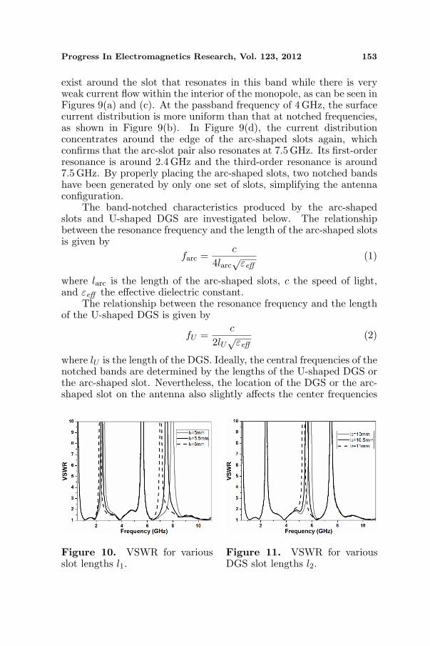
where lU is the length of the DGS. Ideally, the central frequencies of thenotched bands are determined by the lengths of the U-shaped DGS orthe arc-shaped slot. Nevertheless, the location of the DGS or the arc-shaped slot on the antenna also slightly affects the center frequencies
Figure 10. VSWR for variousslot lengths l1.
Figure 11. VSWR for variousDGS slot lengths l2.
154 Liu et al.
of the notched bands. Therefore, the above formulas have been usedto obtain initial design parameters for the resonant elements. Theseparameters have been optimized later with Microwave Studio full-wavesimulations.
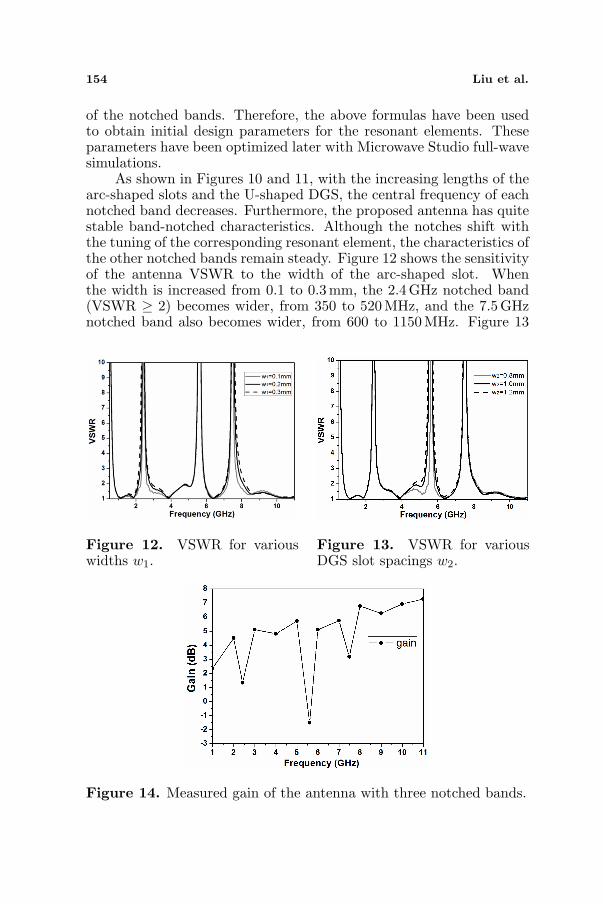
As shown in Figures 10 and 11, with the increasing lengths of thearc-shaped slots and the U-shaped DGS, the central frequency of eachnotched band decreases. Furthermore, the proposed antenna has quitestable band-notched characteristics. Although the notches shift withthe tuning of the corresponding resonant element, the characteristics ofthe other notched bands remain steady. Figure 12 shows the sensitivityof the antenna VSWR to the width of the arc-shaped slot. Whenthe width is increased from 0.1 to 0.3 mm, the 2.4 GHz notched band(VSWR ≥ 2) becomes wider, from 350 to 520 MHz, and the 7.5GHznotched band also becomes wider, from 600 to 1150 MHz. Figure 13
Figure 12. VSWR for variouswidths w1.
Figure 13. VSWR for variousDGS slot spacings w2.
Figure 14. Measured gain of the antenna with three notched bands.

Progress In Electromagnetics Research, Vol. 123, 2012 155
shows how the antenna VSWR depends on the spacing between thetwo DGS slots. A wider notched band can be observed from 710 to1260MHz, when the spacing is increased from 0.8 to 1.2 mm. Theseresults indicate that the bandwidth of the notches can be adjusted byaltering the shapes and width of the slots.
Figure 14 displays the measured gain of the antenna with multiplenotched bands. Between 1GHz and 11 GHz, three significant drops ofthe gain can be observed. The frequencies of the minima correspondto the center frequencies of the notched bands. These results confirmthe expected suppression of radiation in the notched frequency bands.
4. CONCLUSION
Three notched bands have been created within the operatingbandwidth of a printed extremely wideband antenna, which otherwisehas a continuous measured 2 : 1 VSWR bandwidth from 0.72GHzto more than 25GHz. This is achieved by introducing a DGS andtwo open arc-shaped slots. The notches have been tuned to preventinterference from WLAN (both 2.4 and 5.5GHz) bands and downlinkX-band satellite communication systems (7.5 GHz). The performanceof the proposed antenna has been investigated. Due to its extremelywide bandwidth, it can support multiple communication services whileavoiding interference from other selected systems.
ACKNOWLEDGMENT
This work has been supported by the Australian Research Council,the Shanghai Leading Academic Discipline Project under GrantNo. S30108, Macquarie University Research Excellence Scholarship(MQRES) scheme and CSIRO Postgraduate Scholarship.
REFERENCES
1. Zhang, Z. and Y. H. Lee, “A robust cad tool for integrated designof UWB antenna system,” Progress In Electromagnetics Research,Vol. 112, 441–457, 2011.
2. Jiang, W., T. Hong, Y. Liu, S.-X. Gong, Y. Guan, and S. Cui,“A novel technique for radar cross section reduction of printedantennas,” Journal of Electromagnetic Waves and Applications,Vol. 24, No. 1, 51–60, 2010.

156 Liu et al.
3. Dissanayake, T., K. P. Esselle, and Y. H. Ge, “A printedtriangular-ring antenna with a 2 : 1 bandwidth,” Microwave Opt.Tech. Lett., Vol. 44, No. 1, 51–53, 2005.
4. Liang, X. L., S.-S. Zhong, and W. Wang, “Tapered CPW-fedprinted monopole antenna,” Microwave Opt. Tech. Lett., Vol. 48,No. 7, 1411–1413, 2007.
5. Lin, C.-C. and H.-R. Chuang, “A 3–12 GHz UWB planartriangular monopole antenna with ridged ground-plane,” ProgressIn Electromagnetics Research, Vol. 83, 307–321, 2008.
6. Saleem, R. and A. K. Brown, “Empirical miniaturization analysisof inverse parabolic step sequence based UWB antennas,” ProgressIn Electromagnetics Research, Vol. 114, 369–381, 2011.
7. Zhu, F., S.-C. Gao, A. T. S. Ho, T. W. C. Brown, J. Li, and J.-D. Xu, “Low-profile directional ultra-wideband antenna for see-through-wall imaging applications,” Progress In ElectromagneticsResearch, Vol. 121, 121–139, 2011.
8. Chen, Z. and Y.-P. Zhang, “Effects of antennas and propagationchannels on synchronization performance of a pulse-based ultra-wideband radio system,” Progress In Electromagnetics Research,Vol. 115, 95–112, 2011.
9. Xu, H.-Y., H. Zhang, K. Lu, and X.-F. Zeng, “A holly-leaf-shapedmonopole antenna with low RCS for UWB application,” ProgressIn Electromagnetics Research, Vol. 117, 35–50, 2011.
10. Thomas, K. G. and M. Sreenivasan, “Printed elliptical monopolewith shaped ground plane for pattern stability,” Electronic Lett.,Vol. 45, No. 9, 445–446, 2009.
11. Yildirim, B. S., B. A. Cetiner, G. Roqueta, et al., “Integratedbluetooth and UWB antenna,” IEEE Antennas and WirelessPropag. Lett., Vol. 8, 149–152, 2009.
12. Liu, J. J., S. S. Zhong, and K. P. Esselle, “A printed ellipticalmonopole antenna with modified feeding structure for bandwidthenhancement,” IEEE Trans. Antennas Propag., Vol. 59, No. 2,667–670, 2011.
13. Habib, M. A., A. Bostani, A. Djaiz, M. Nedil, M. C. E. Yagoub,and T. A. Denidni, “Ultra wideband CPW-FED aperture antennawith WLAN band rejection,” Progress In ElectromagneticsResearch, Vol. 106, 17–31, 2010.
14. Hu, Y.-S., M. Li, G.-P. Gao, J.-S. Zhang, and M.-K. Yang,“A double-printed trapezoidal patch dipole antenna for UWBapplications with band-notched characteristic,” Progress InElectromagnetics Research, Vol. 103, 259–269, 2010.

Progress In Electromagnetics Research, Vol. 123, 2012 157
15. Su, M., Y. Liu, S. Li, and C. Yu, “A compact open slot antennafor UWB applications with band-notched characteristic,” Journalof Electromagnetic Waves and Applications, Vol. 24, No. 14–15,2001–2010, 2010.
16. Barbarino, S. and F. Consoli, “UWB circular slot antennaprovided with an inverted-L notch filter for the 5 GHz WLANband,” Progress In Electromagnetics Research, Vol. 104, 1–13,2010.
17. Xie, L., Y.-C. Jiao, Y.-Q. Wei, and G. Zhao, “A compactband-notched UWB antenna optimized by a novel self-adaptivedifferential evolution algorithm,” Journal of ElectromagneticWaves and Applications, Vol. 24, No. 17–18, 2353–2361, 2010.
18. Zhou, H. J., Q.-Z. Liu, Y.-Z. Yin, and W. B. Wei, “Studyof the band-notch function for swallow-tailed planar monopoleantennas,” Progress In Electromagnetics Research, Vol. 77, 55–65,2007.
19. Dissanayake, T. and K. P. Esselle, “Prediction of the notchfrequency of slot loaded printed UWB antennas,” IEEE Trans.Antennas Propag., Vol. 55, No. 11, 3320–3325, 2007.
20. Wei, Y.-Q., Y.-Z. Yin, L. Xie, K. Song, and X.-S. Ren, “A novelband-notched antenna with self-similar flame slot used for 2.4GHzWLAN and UWB application,” Journal of Electromagnetic Wavesand Applications, Vol. 25, No. 5–6, 693–701, 2011.
21. Yang, G., Q.-X. Chu, and Z.-H. Tu, “A compact band-notched UWB antenna with controllable notched bandwidthsby using coupled slots,” Journal of Electromagnetic Waves andApplications, Vol. 25, No. 14–15, 2148–2157, 2011.
22. Qu, X. A., S. S. Zhong, and W. Wang, “Study of the band-notchfunction for a UWB circular disc monopole antenna,” MicrowaveOpt. Technol. Lett., Vol. 48, No. 8, 1667–1670, 2006.
23. Xie, M., Q. Guo, and Y. Wu, “Design of a miniaturizedUWB antenna with band-notched and high frequency rejectioncapability,” Journal of Electromagnetic Waves and Applications,Vol. 25, No. 8–9, 1103–1112, 2011.
24. Deng, J. Y., Y. Z. Yin, J. Ma, and Q. Z. Liu, “Compactultra-wideband antenna with dual band-notched characteristic,”Journal of Electromagnetic Waves and Applications, Vol. 23,No. 1, 109–116, 2009.
25. Li, C.-M. and L.-H. Ye, “Improved dual band-notched UWBslot antenna with controllable notched bandwidths,” Progress InElectromagnetics Research, Vol. 115, 477–493, 2011.

158 Liu et al.
26. Zhang, M., X. Zhou, J. Guo, and W. Yin, “A novel ultrawidebandplanar antenna with dual band-notched performance,” MicrowaveOpt. Tech. Lett., Vol. 52, No. 1, 90–92, 2010.
27. Chu, Q. X. and Y. Y. Yang, “3.5/5.5 GHz dual band-notch ultra-wideband antenna,” Electronic Lett., Vol. 44, No. 3, 172–174,2008.
28. Anagnostou, D. E., S. Nikolaou, H. Kim, B. Kim, M. Tentzeris,and J. Papapolymerou, “Dual band-notched ultra-widebandantenna for 802.11a WLAN environments,” 2007 IEEE Antennasand Propagation Society International Symposium, 4621–4624,2007.
29. Xia, Y.-Q., J. Luo, and D.-J. Edwards, “Novel miniature printedmonopole antenna with dual tunable band-notched characteristicsfor UWB application,” Journal of Electromagnetic Waves andApplications, Vol. 24, No. 13, 1783–1793, 2010.
30. Ni, T., W.-M. Li, Y.-C. Jiao, L.-S. Ren, and L. Han, “Novel com-pact UWB antenna with 3.5/5.5 GHz band-notched characteris-tics,” Journal of Electromagnetic Waves and Applications, Vol. 25,No. 16, 2212–2221, 2010.
31. Wang, M., J.-X. Xiao, and S. Wang, “Study of a dual-band notched wideband circular slot antenna,” Journal ofElectromagnetic Waves and Applications, Vol. 24, No. 17–18,2445–2452, 2010.
32. Li, Z.-Q., C.-L. Ruan, and L. Peng, “Design and analysis of planarantenna with dual WLAN band-notched for Integrated Bluetoothand UWB applications,” Journal of Electromagnetic Waves andApplications, Vol. 24, No. 13, 1817–1828, 2010.
33. Ren, L.-S., F. Li, J.-J. Zhao, G. Zhao, and Y.-C. Jiao, “A novelcompact UWB antenna with dual band-notched characteristics,”Journal of Electromagnetic Waves and Applications, Vol. 24,No. 11–12, 1521–1529, 2010.
34. Nikolaou, S., M. Davidovic, M. Nikolic, and P. Vryonides, “Triplenotch UWB antenna controlled by three types of resonators,” 2011IEEE International Symposium on Antennas and Propagation(APSURSI), 1478–1481, 2011.
35. Nguyen, T. D., D. H. Lee, and H. C. Park, “Design and analysisof compact printed triple band-notched UWB antenna,” IEEEAntennas and Wireless Propag. Lett., Vol. 10, 403–406, 2011.
36. Liao, X.-J., H.-C. Yang, N. Han, and Y. Li, “A semi-circle-shapedaperture UWB antenna with triple band-notched characteristics,”Journal of Electromagnetic Waves and Applications, Vol. 25,No. 2–3, 257–266, 2011.
Copyright © 2022 FDOKUMEN