IFITM proteins are incorporated onto HIV-1 virion particles and negatively imprint their infectivity
Upload
independentCategory
view
1download
0
1
Flow behaviour of negatively buoyant jets in immiscible ambient fluid
Geyer, A. (1)(2), Phillips, J. (3) , De Mier, M. (1) , Idelsohn, S. (1) *, Oñate, E. (1)
1. CIMNE International Center for Numerical Models in Engineering, UPC Campus Norte , Edificio C1, C/
Gran Capitán s/n , 08034 Barcelona, Spain
2. Institute of Earth Sciences Jaume Almera, CSIC, c/Lluis Solé i Sabaris s/n, 08028 Barcelona ,Spain
3. Department of Earth Sciences, University of Bristol, Wills Memorial Building, Queen’s Road, Bristol BS8 1RJ,
UK
* ICREA Research Professor
Corresponding author: A. Geyer ([email protected])
Submitted to: Experiments in Fluids
Abstract
In this paper we investigate experimentally the injection of a negatively buoyant jet into a
homogenous immiscible ambient fluid. Experiments are carried out by injecting a jet of dyed
fresh water through a nozzle in the base of a cylindrical tank containing rapeseed oil. The
fountain inlet flow rate and nozzle diameter were varied to cover a wide range of Richardson Ri
(8×10⁻⁴ < Ri < 1.98) , Reynolds Re (467 < Re < 5928) and Weber We (2.40 < We < 308.56)
numbers. Based on the Re, Ri and We values for the experiments, we have determined a regime
map to define how these values may control the occurrence of the observed flow types. Whereas
Riplays a stronger role when determining the maximum penetration height, the effect of the
Reynolds number is stronger predicting the flow behaviour for a specific nozzle diameter and
injection velocity.
Keywords: Negatively buoyant jet, collapsing fountain, immiscible fluids, laboratory experiments
THIS MANUSCRIPT CORRESPONDS TO THE POST-PRINT DOCUMENT OF THE FOLLOWING PAPER:
Geyer, A., Phillips, J., Mier-Torrecilla, M., Idelsohn, S. and Oñate, E., 2012. Flow behaviour of negatively buoyant jets in immiscible ambient fluid. Experiments in Fluids, 52(1): 261-271.

2
1. Introduction
When a dense fluid is injected vertically upward into a lighter fluid, its momentum is
continually being decreased by buoyancy forces until the vertical velocity becomes zero at some
finite distance from the source. As the jet reaches its maximum penetration length hmax, it
reverses its direction and flows back in an annular geometry around the upflow (Fig. 1). Such
jets are called negatively buoyant jets or fountains, and the density difference between the
ambient and the injected fluids may be due to a variation in either chemical composition or
temperature. In this paper, we use the term jet to describe the initial upwards motion, and
fountain to describe the collapsing dense flow.
Negatively buoyant jets are common both in engineering and natural science. An everyday
example is the ventilation of large open structures such as aircraft hangars, which are heated
using ceiling-mounted fans to drive hot air towards the floor. In nature, geophysical buoyant jets
resulting from temperature (or salinity) differences can occur in volcanic magma chambers and
in the ocean (e.g. Campbell and Turner 1989, Turner and Campbell 1986).
The flow behaviour of negatively buoyant jets may vary depending on the following
factors (Cresswell and Szczepura 1993, Papanicolaou and Kokkalis 2008, Turner 1966): (i) jet
parameters, (ii) environmental parameters, and (iii) geometrical factors. The first group of
parameters includes the initial jet velocity distribution and turbulence level (whether the jet is
laminar or turbulent), as well as the mass, momentum and buoyancy fluxes. The fountain can be
described as strong or weak depending on the ratio of buoyancy and momentum flux, or if the
fountain is laminar or turbulent. For strong fountains (the discharge momentum is relatively
larger than the negative buoyancy of the flow), the fountain top, plunging plume and intrusion
flow are distinct features (Fig. 1a). Kinetic energy is converted into potential energy until hmax is
reached and then the fluid begins to accumulate at the top of the fountain. As the mass of
accumulated fluid increases, eventually the downward buoyancy force exceeds the inertia of the

3
jet and the collapse occurs. When the falling fluid collapses back to the level of the nozzle, it
dislodges from the jet and a new cycle begins. If the source momentum is further increased, this
oscillatory behaviour persists at increasing amplitudes until a second threshold limit is reached
above which the fountain no longer exhibits high-amplitude pulsations (Clanet 1998). For weak
fountains (discharge inertia of the fountains is equal or less than the negative buoyancy force),
the fluid exiting the fountain remains attached to the nozzle due to capillary and gravity forces,
i.e. the upward and downward flows cannot be visually distinguished. Instead, the streamlines
curve and spread from the source and fountain top (Fig 1b.). The second group of variables,
environmental parameters, includes parameters describing the ambient fluid (e.g. turbulence
level, any net flow, and density stratification) and the geometrical factors include the jet shape,
its orientation and proximity to solid boundaries or to the free surface..

4
Preceding studies suggest that the maximum penetration height hmax of negatively
buoyant jets is related to the momentum and buoyancy fluxes at the source and may be
expresssed in terms of the Richardson Ri and Reynolds Re numbers (Armienti et al. 1984,
Baines et al. 1990, Baines et al. 1993, Lin and Armfield 2000, Lin and Armfield 2003, Lin and
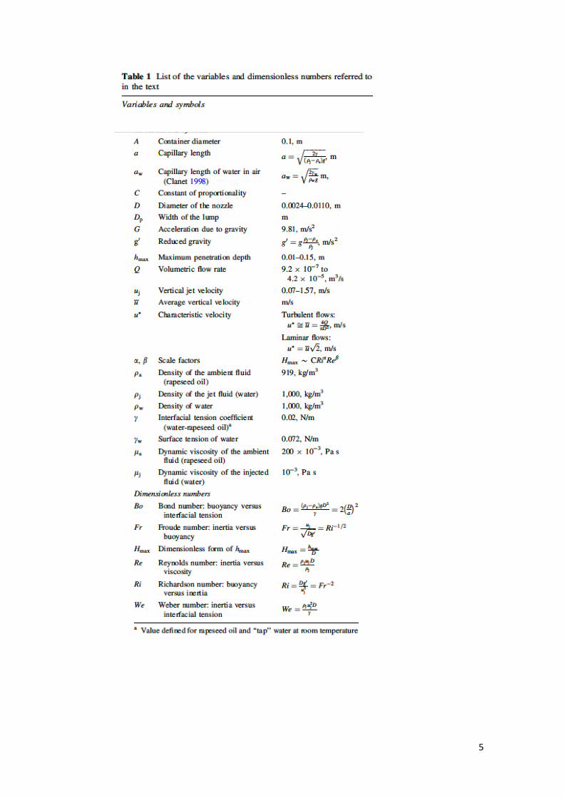
Armfield 2000, Turner 1966), i.e. Hmax ∼CRiα Reβ, where C is a constant of proportionality, α
and β are the scale factors and Hmax is the dimensionless maximum penetration height defined
as hmax / D (Table 1) . Note that the Reynolds number (Re) as defined here characterizes the ratio
between inertia and viscous effects in the flow at the nozzle and the Richardson number (Ri)
compares gravitational potential energy to kinetic energy (Table 1). After numerous
experimental studies, there are significant variations in the reported values of C, α and β that
may be attributed to (List 1982): (1) the methods for defining and measuring the maximum
height; (2) the effect of Reynolds number and (3) the effect of relative density difference and of
mass flux.
Previous experimental works on negatively buoyant jets considering immiscible
ambient-jet fluid pairs have mainly focused on the dynamics of drop formation (Chatterjee and
Bradshaw 1972, Meister and Scheele 1696), the estimate of the rise height/jet length (Banks and
Chandrasekhara 1963, Friedman 2006, Friedman and Katz 2000, Meister and Scheele 1969) and
to a lesser extent, the flow behaviour of the jet depending on the diverse dimensionless numbers
(Friedman and Katz 1999, Friedman et al. 2006, Friedman et al. 2007). Nevertheless, some
aspects concerning the dynamics of negatively buoyant jets with immiscible ambient-fluid pairs
are still poorly understood.
5

6
In this paper we investigate experimentally the flow behaviour of a negatively buoyant jet in
a homogenous immiscible ambient fluid by injecting a jet of dyed water through a nozzle in the
base of a cylindrical tank containing rapeseed oil. One of the main differences between our and
previous experiments (Friedman and Katz 1999, Friedman et al. 2006, Friedman et al.
2007)(apart from the experimental fluids and their physical properties) is the geometry we are
using (Fig. 2): a re-entrant conical nozzle located at the base of the tank whereas in their
experiments, they used a bottom issuing fountain (see Fig. 1 Friedman et al. 2006). In the
different experiments, we have varied the injection velocity and the nozzle radius to reproduce a
wide range of Reynolds, Richardson and Weber numbers. The experiments presented in this
paper cover a larger Richardson number interval, 8×10⁻⁴ < Ri< 1.98 , than previous studies
and are able to reproduce both weak and strong fountains in both turbulent and laminar regimes
(468 < Re < 5928). In contrast to previous published results, data obtained allow us to describe
three different fountain behaviours (Type I, II and III). Based on the Re , Ri and We values of
the numerical and experimental simulations, we present different regime maps to define how Re
, Ri and We may control the observed fountain behaviours.

7
2. Experiments
Experiments were conducted in which dyed water was injected into the base of a cylindrical
tank containing rapeseed oil to form a collapsing fountain (Fig. 2). The water was injected
through a re-entrant conical nozzle with taper angle of 4.5 +/- 0.3 degrees, and the inlet flow
rate was kept constant over the duration of the experiment using a constant-head supply tank.
The nozzle was situated in the centre of the cylindrical tank, which was 0.1 m in diameter and
0.3 m deep, and it was filled to a depth of 0.25 m with rapeseed oil (Fig. 2). The fountain inlet
flow rate and nozzle diameter were varied to cover a wide range of Reynolds, Richardson and
Weber number interval, 468< Re < 5928, 8×10⁻⁴ < Ri< 1.98 and 2.40 < We < 308.56,
respectively. The volume flow rate Q varied from 0.9 cm3/s to 42 cm3/s and was determined
from the rate of change of elevation in the test chamber. The calculated accuracy of the
measurement is +/-2.5%. Besides, the nozzle diameter was varied from 2.4 mm to 11 mm. The
motion of the collapsing fountain was recorded using a digital camera with resolution in time of
less than 0.1s and each pixel is 0.001 x 0.001 cm. The experiments were run for sufficiently
short times so that the depth of liquid in the tank, hence the hydrostatic pressure, was not
significantly increased.
3. Results
3.1 Description of the flow regimes
Our experimental results show that, for a given fountain geometry, the fountain exhibits
distinct flow regimes as the inlet volumetric flow rate is increased, as previously observed in
other experimental studies (Friedman and Katz 1999, Friedman et al. 2006, Friedman et al.
2007). Based on the results obtained, we have been able to categorize three different flow
regimes based on the behaviour of the fountain (Fig. 3): Type I, II and III. Flow regime I is
characterised by an approximately constant fountain height, within the range of experimental
error of the observation (Fig. 3a). In the case of Type II (pulsating) flow behaviour (Fig. 3b), the

8
fountain height is not constant, but varies continuously with time t between a maximum hmax and
a minimum height hmin. Finally, Type III behaviour is characterised by the jet initially
penetrating upward into the ambient fluid and when reaching hmax, a “cap” of accumulated jet
fluid forms at the top of the jet. The size of this cap increases due to the continuous fluid supply
from the fountain, but its vertical position remains constant at hmax. Once the cap exceeds a
critical size, it breaks up and water droplets fall back to the base of the tank (Fig. 3c). In this
regime, the fountain is characterized by a smooth and a wavy part (Fig. 3).
3.2 Dimensional analysis
As adopted in various previous publications, dimensional analysis may help to understand
and delimit the different flow regimes observed for negatively buoyant jets (e.g. Friedman 2006,
Kaye and Hunt 2006). However, an apparently unresolved issue is the choice of length scale to
adopt in dimensionless groups (see Table 1). There appears to be general consensus in selecting
the width of the nozzle, but some studies use the radius and others the diameter as characteristic
lengths (Table 2). This discrepancy is very important when comparing the results obtained from
the different studies. Here, we choose the nozzle diameter as the length scale for the flow, on the
simple basis that this is the length defined by the solid boundaries of the flow.

9
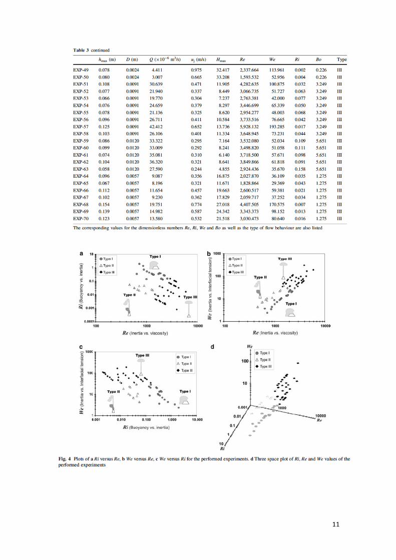
For each experiment, the values for the dimensionless number considered for the analysis
are listed in Table 3 and have been plotted in pairs and on a Re-Ri-We three space in Figure 4..
Note that whereas the Re and Ri numbers characterize the ratio inertia vs. viscous or buoyancy
effects, respectively, interfacial tension effects are non-dimensionalized in the Weber number
(Table 1).
For Type I and II behaviour, inertial forces are less important than viscosity or interfacial
tension, contrary to the case of Type III experiments for which inertia dominates (Fig. 4).
Besides, buoyancy dominates over inertia effects for Type I experiments, but not for Type II
and III (Fig. 4b).
From Figure 4c it is obvious that the transition between Type I and II behaviours to Type III
occurs at an approximate constant We ≈ 35 (Fig. 4b and c), over We>35 only Type III behaviour
is observable. Type I and II are restricted to We < 35 and the change from one to the other is
mainly controlled by the Ri number (Fig. 4c).Type I flow regime is observable for Ri >0.13

10
values and below 0.05 only Type II behaviour is observable. In the transition, regime
0.05<Ri<0.13, both Type I or II flow may occur. A more accurate definition of this limit
between Type I and II needs further experimental results.
11

12
In Figure 5 we have plotted Hmax against Ri and Re, respectively. There is a clear separation
between Type I and III flow regimes at Ri ≈ 0.13, which is not the case between Type II and III
which occur over the same Ri - Hmax range (Fig. 5a). In their work Friedman and Katz (2000)
proposed that three power law relationships are able to explain the penetration depth of a
negatively buoyant jet in terms of Ri and a jet spreading factor F (see Friedman and Katz, 2000
for more details). The paper showed that for Ri/F2<0.2 the maximum penetration height can be
predicted by 5.02max )/(2.2 −= FRiH and for Ri/F2>0.2, 12
max )/( −= FRiH . The third power
law relationship is applied for Ri/F2>2 and 1/D<< 1, which is not the case of our experimental
results. In their paper Friedman and Katz (2000) stated that these power law correlations fit a
wide variety of published data, including miscible and immiscible fluids.

13
Considering that for the experimental set-up used in this paper F = 1 (Friedman and Katz
2000), the correlation of our data with Ri <0.2 is quite consistent with the one proposed by
Friedman and Katz (2000) (Fig. 5a), namely: 45.0max )(76.2 −= RiH . Differences between our
correlation and the one proposed by Friedman and Katz (2000) may be related to experimental
errors included in both data set. From the results plotted in Figure 5a is evident that our
experiments fit also the power law 1max
−= RiH for Ri >0.2.
Friedman (2006) suggest that, apart from predicting the onset of turbulence, the value of
Re has no further effect. However, other authors have seen that the limits of stability are
dependent on Re (e.g. Lin and Armfield 2003, Lin and Armfield 2004). This observation is clear
in Figure 5b. All three different flow types can be categorized by values of Hmax and Re. Thus, it
is evident that Re plays a role when describing the different flow behaviours and Ri is a key
parameter to determine the maximum penetration height.
4. Discussion
4.1 Laminar or turbulence flow
Whereas Type I and II behaviours occur approximately over the same range of Re numbers
(467 < Re < 2500), Type III behaviour occurs at higher values Re (1500 < Re < 5928)(Table 3).
An important issue is what flow regimes (e.g. laminar, transitional or turbulent) these ranges of
Re pertain to for a negatively-buoyant jet. For example, in the case of pipe flow, the transition
region is approximately in the interval 2000 < Re < 4000, so if these limits were appropriate for
a negatively-buoyant jet, our experimental Re values would correspond principally to a laminar
but also partially a transitional regime (for Type I and II) and for Type I mainly to the
transitional but also the turbulent regime (Table 3).
However, previous studies of negatively-buoyant jets have established no consensus as to
the regime delimiting values of Re. Pearce (1966) on the basis of visual observations using dye
of the structure of nearly non-buoyant jets over a Reynolds number range of 68 to 13,100,

14
establishing in general terms that the jet was essentially laminar for Re < 500 and fully turbulent
for Re > 3000. Values of Re in between, lead to a transitional regime where a part of the jet
behaved as laminar and the other as turbulent. Another interesting classification is that proposed
by Williamson et al. (2008), who established the laminar-transitional threshold at Re = 240 and
the transitional-turbulent at Re = 4000. Considering both Pearce (1966) and Williamson et al.
(2008) definitions, all Type I and II experiments would lay in the transitional regime whereas
Type III would be transitional to turbulent. Future studies need to investigate this aspect in
detail and to try to define the limits for the laminar and turbulent regime for negatively buoyant
jets in immiscible fluids since it can provide an important control on the mixing process of both
fluids as suggested by Friedman et al. (2006).
4.2 “Stable” vs. “unstable” regime
Our experimental results, in agreement with previous published studies (Friedman and Katz
1999, Friedman et al. 2006, Friedman et al. 2007), show that for a given fountain geometry and
ambient-jet fluid pair, the fountain behaviour transitions through distinct flow regimes as the
volumetric flow rate (i.e. the vertical jet velocity) increases. Friedman and co-workers
(Friedman et al. 2006, Friedman et al. 2007) suggest that the most significant transition (referred
as the “instability threshold”, IT) occurs when the flow pattern passes from a “stable” regime
where the buoyancy, interfacial tension and viscosity dominate, to an “unstable” regime where
momentum dominates. The stable flow regime is characterized by a low, wide and rapidly-
collapsing fountain, while the unstable flow regime corresponds to a taller and narrower
fountain that periodically collapses and reforms with a characteristic collapse frequency.
Friedman and co-workers (Friedman 2006, Friedman and Katz 1999, Friedman et al. 2006,
Friedman et al. 2007) define the instability threshold using only the Richardson number and
suggest that the transition between regimes occurs at approximately RiIT = 1 for turbulent flow
and RiIT = 2 for laminar flow.

15
It is important to note that Friedman et al. (2006) suggested that the Re dependency can be
eliminated by defining Ri in terms of the characteristic velocity (u*), which is representative of
the momentum of the flow. For turbulent flows, with a nearly uniform velocity profile, the
characteristic jet velocity is approximately equal to the volumetric flow rate Q divided by the
cross-sectional area of the source )DQ
u*u( 2
4π
=≅ , while for laminar flows, the characteristic
velocity is defined as the root mean square velocity (u* = 2u ) to account for additional
momentum(Friedman et al. 2006) The effect of Re may be incorporated by defining a corrected
Richardson number (RiC). For the turbulent regime (nominally Re >2300), RiC = Ri and RiC =
Ri/2 for the laminar regime (Re< 2300). In this way, the instability thresholds defined above
using RiC is RiITC = 1 in both regimes, laminar and turbulent. In common with previous studies
(Lin and Armfield 2000, Lin and Armfield 2003, Lin and Armfield 2004), we consider
necessary to independently analyze the dependence of the flow on Re and Ri, and therefore, we
have not corrected Ri.
Whereas Friedman et al. (2006, 2007) propose only a two end-member classification as
“stable” and “unstable” jets, our experiments identify three distinct flow regimes: Type I, II and
III. In the broadest sense, our Type I experiments correspond to the “stable” regime, and our
Type II and III experiments exhibit periodic collapsing, which would correspond both to
“unstable” flows. However, there is a clear distinction between the collapse mechanism for
Type II and III experiments that is not captured in the simple classification proposed by
Friedman and co-workers (Friedman 2006, Friedman and Katz 1999, Friedman et al. 2006,
Friedman et al. 2007). Although some fluctuations of the column are observed in Type III
flows, they are not related to a collapse of the fountain as is the case of the jets in Type II
regime but to the growth and breakup of the cap region.
Additionally, the instability threshold defined at RiIT = 1 for turbulent flow and RiIT = 2 for
laminar flow is not directly applicable to our results. According to Figure 9, our instability
threshold (transition between Type I and II) occurs at Ri ≈ 0.13. However, the discrepancy

16
between the Ri values for instability threshold may be due to the high interfacial tension
between oil and water. The critical Richardson number RiIT has been shown to depend on the
interfacial tension γ between both fluids, and the viscosity ratio µj/µa (Friedman et al. 2007).
Interfacial tension contributes to the stability of the fountain and thus decreases RiIT . Viscosity
ratios deviating from unity also stabilize the fountain, inhibit the formation of waves on the
interface, and delay or even suppress the jet breakup into droplets (Campbell and Turner 1989).
In our experiments, µj/µa = 0.005, outside the range of values considered by Friedman et al.
(2007), but their results indicate that RiITC may decrease from 1 to 0.7 when reducing viscosity
ratio from 1 to µj/µa = 0.2. Considering the differences in viscosity ratios between our study and
that of Friedman et al. (2007), we do not expect agreement on the values of RiIT
Clanet (1998) presented results from a study of a water jet injected vertically upwards
into air which showed that depending on the initial momentum flux (∼ ρuj2), water fountains
exhibit distinct modes of behaviour . For very low-momentum fluxes, the water exiting the
fountain remains attached to the nozzle due to capillary and gravity forces (Dias et al. 1990) .
For values of the momentum flux above a certain threshold, a second regime is achieved where
the fluid detaches from the nozzle, forming an upward moving jet that accumulates a region of
fluid at the tip of the fountain. As the mass of this region increases, the gravitational force
eventually overcomes the jet's inertia and the lump begins to fall. As it reaches the nozzle, it
dislodges from the jet and a new cycle begins. This rising and falling process repeats itself in a
periodic or quasi-periodic fashion resulting in large-amplitude oscillations in the fountain
height. As the water momentum flux is further increased, this oscillatory behaviour persists at
increasing amplitudes until a second threshold limit is reached above which the fountain no
longer exhibits high-amplitude pulsations. According to his description, Clanet (1998) also
observes three flow regimes controlled primarily by the momentum flux (expressed in
dimensionless form as the Ri number).
In two of the three experimental studies available for the injection of a negatively
buoyant jet in an immiscible ambient fluid (Clanet (1998) and our experiments) three flow

17
regimes are observable. By contrast, in their experiments, Friedman et al. (2006, 2007) are able
to observed only two flow regimes. These differences can be explained due to differences in the
experimental geometry and the physical properties of the fluids used. Friedman et al. (2006,
2007) used a nozzle whose exist was located at the same level as the base of the tank. By
contrast, our study and that of Clanet (1998) use a re-entrant nozzle whose exit is located away
from the solid boundary of the tank. In addition, the diameters of the nozzles used varied from
less than one millimetre (Clanet 1998) to several centimetres (Friedman et al. 2006, Friedman et
al. 2007). Whereas our range of D values (2.4-11 mm) allows us to observe flow behaviours
characteristic for narrow to intermediate size nozzles, Friedman et al. (2006, 2007) and Clanet
(1998) observations are restricted to large and narrow nozzles, respectively. Comparing the D
values used by Clanet (1998) (0.318-4.1 mm) with our own and noting that both experiments
use water as the injected fluid, we would expect some similarity of qualitative observations.
However, since the ambient fluid is not the same in both cases (Clanet (1998) injects water into
air), results obtained are slightly different as explained in the next section.
4.3 Type II behaviour: The “pulsating” regime
Following the work of Clanet (1998) we now consider the region of existence of the Type II
“pulsating” regime According to Clanet (1998), the pulsating mode starts once the jet
momentum flux is high enough to overcome capillary and gravity forces. There are two
different mechanisms leading to the threshold between Type II and III (end of the pulsating
regime). The first originates in the capillary instability of the Rayleigh-type undergone by the
cylindrical jet, which is unstable with respect to disturbances of wavelengths larger than the jet
circumference. As the height of the fountain is increased, this instability has time to develop so
that the jet breaks into droplets prior to reaching the maximum height. When these droplets
migrate from the axis a sufficient distance, preventing them from interacting with the ascending
fluid, the driving cause of the oscillation is lost and the fountain exhibits a quasi-constant
height, close to its maximum height hmax. If the breakup process was symmetric for all times, all

18
the drops would stay on the axis of symmetry and the oscillations would persist independently
of the Rayleigh instability. However, as the jet breaks up, the drops acquire a small radial
velocity. When the drops have time to migrate a distance of the order of the jet diameter D
before they reach hmax, the oscillations stop. An additional physical phenomenon affecting the
stability of large-diameter fountains occurs when the dynamic pressure of the jet ∼ρuj2, becomes
of the same order of magnitude as the surface tension restoring action, ∼4γ/Dp being Dp the
width of the lump (Clanet 1998, Taylor 1963). In this limit, the region of accumulated liquid at
the fountain topbursts close to its maximum height and no large-amplitude oscillations are
observed.
In the case of water fountains, the pulsating regime exists within the limits 0.63 ≤ aw / D ≤
10 and 20 ≤ uj 2 / gD ≤ 400, where aw is the capillary length of water in air defined as (Clanet,
1998): aw = (2γw / (ρw g))1/2, ρw and γw being density and surface tension of water, respectively
(Table 1). Notice that uj 2 / gD is a reciprocal of the Richardson number with the reduced gravity
removed and aw/D is directly related to a Bond number for the experiment considering that the
characteristic length is the nozzle diameter (Table 1). Thus, we have analyzed the range of our
data in terms of the latter dimensionless numbers Ri and Bo and compared them with the
existence domain for the large-amplitude oscillating fountains defined by Clanet (1998) (Fig.6)

19
From Figure 6 we observe that several of the experiments where Type II (pulsating)
behaviour has been observed fall into the region of existence of the pulsating regime observed
for water fountains in air (Clanet 1998). However, also some of our Type I experiments fall
into the pulsating regime defined by Clanet (1998). A simple explanation for this observation is
the fact that we are using a different ambient fluid, i.e. rapeseed oil instead of air. For our
experimental configuration we estimate the capillary length of water into rapeseed oil correcting
the definition of Clanet (1998) with the density difference between both fluids a = (2γ /((ρj -ρa
)g))1/2 (e.g. Aarts, 2005)(Table 1). A simple calculus using the values for γw, γ, ρw, ρ and g listed
in Table 1 allows us to identify that a w≈ 0.54 a , i.e. according to the definition of the Bond
number used in this work (Table 1) the Bo values for the immiscible ambient-jet fluid pair are
around three times those provided by Clanet (1998). Thus, since the capillary length of water in
air aw is half the one of water in oil a, for the same uj 2 / gD or Ri-1 , the pulsating regime
defined by Clanet (1998) for water fountains in air is displaced right in the graph of Figure 6
5. Summary and Conclusions
In this study we have investigated experimentally the dynamics of negatively buoyant jets
in a homogenous immiscible ambient fluid. Experiments are carried out by injecting coloured
water into a cylindrical tank containing rapeseed oil. The water is injected using a re-entrant
trimmed conical nozzle and maintained at a constant flow rate throughout the experiment. The
fountain inlet flow rate and nozzle diameter were varied to cover a wide range of Reynolds,
Richardson and Weber number interval, 468< Re < 5928, 8×10⁻⁴ < Ri< 1.98 and 2.40 < We <
308.56, respectively.
In contrast to many previous published studies that propose two end-member classifications
of fountain behaviour: “stable” and “unstable”, our experimental results show three distinct flow
regimes:

20
- Type I behaviour is characterised as very stable. The height of the fountain is
approximately constant although we cannot discount very small fluctuations of the column
height within the systematic measurement error .
- Type II behaviour is described as a pulsating fountain for which height oscillates
continously with time from a maximum hmax to a minimum height hmin.
- Type III behaviour is observable for higher injection velocities. The jet initially penetrates
upward into the ambient fluid and when it reaches hmax , a “cap” forms at the top of the jet. The
fountain is characterized by a smooth and a wavy part.
Based on the Re, Ri and Bo values for the experimental simulations, we have determined a
regime map to define how these values may control the occurrence of each of the observed flow
types. We find that Ri may play a stronger role compared to Re to determine the penetration of
the maximum penetration height. By contrast, the effect of the Reynolds and We numbers may
be stronger than Ri’s to provide a prediction of the flow behaviour for a specific nozzle
diameter and injection velocity. The transition between Type I and II is uniquely controlled by
the Ri number and there is a clear control of the Weber number when passing from Type I or II
to Type III.
The region of existence of the Type II (pulsating) regime coincides with the one observed
for water fountains in air (Clanet 1998). The main difference is due to the fact that the capillary
length of water in air is half the one of water in rapeseed oil.
6. Acknowledgements
M. Mier-Torrecilla thanks the Catalan Agency for Administration of University and Research
Grants (AGAUR), the European Social Fund and CIMNE for their support. AG is grateful for
her post-doctoral Beatriu de Pinós Grant (2008 BP B 00318) and her Juan de la Cierva Grant
(JCI-2010-06092). We thank three anonymous reviewers for their interesting comments that

21
have helped us to improve the previous version of this manuscript. This work was partially
supported by the European Research Council under the Advanced Grant: ERC-2009-AdG “Real
Time Computational Mechanics Techniques for Multi-Fluid Problems”.
7. References
Armienti P, Barberi F, Innocenti F (1984) A model of the Phelgraean Fields magma chamber in the last 10,500 years. Bulletin of Volcanology 47:349-358
Baines WD, Corriveau AF, Reedman TJ (1990) Turbulent fountains in a open chamber. Journal of Fluid Mechanics 212:557-592
Baines WD, Corriveau AF, Reedman TJ (1993) Turbulent fountains in a closed chamber. Journal of Fluid Mechanics 255:621-646
Banks RB, Chandrasekhara S (1963) Experimental investigation of the penetration of a high-velocity gas jet through a liquid surface. Journal of Fluid Mechanics 15:13-34
Campbell IH, Turner J, S (1989) Fountains in magma chambers. Journal of Petrology 30:885-923
Clanet C (1998) On large-amplitude pulsating fountains. Journal of Fluid Mechanics 366:333-350
Cresswell RW, Szczepura RT (1993) Experimental investigation into a turbulent jet with negative buoyancy. Physics of Fluids 5:2865-2878
Chatterjee A, Bradshaw AV (1972) Breakup of a Liquid Surface by an Impinging Gas Jet. Journal of the Iron and Steel Institute 210:179-187
Dias F, eacute, ric, Vanden-Broeck J-M (1990) Flows emerging from a nozzle and falling under gravity. Journal of Fluid Mechanics 213:465-477 DOI doi:10.1017/S0022112090002403
Friedman PD (2006) Oscillation in heigth of a negatively bouyant jet. Transactions to the ASME 128:880-882
Friedman PD, Katz J (1999) The flow and mixing mechanisms caused by the impingement of an inmiscible interface with a vertical jet. Physics of Fluids 11:2598-2606
Friedman PD, Katz J (2000) Rise Height for Negatively Buoyant Fountains and Depth of Penetration for Negatively Buoyant Jets Impinging an Interface. ASME Journal of Fluids Engineering 122:779-782
Friedman PD, Meyer Jr WJ, Carey S (2006) Experimental simulation of phase mingling in a subaqueous lava fountain. Journal of Geophysical Research 111:B07201
Friedman PD, Vadakoot VD, Meyer Jr WJ, Carey S (2007) Inestability threshold of a negatively bouyant fountain. Experimental Fluids 42:751-759
Kaye NB, Hunt GR (2006) Weak fountains. Journal of Fluid Mechanics 558:319-328 Lin W, Armfield SW (2000) Very weak fountains in a homogeneous fluid. Numerical
Heat Transfer, Part A 38:377-396 Lin W, Armfield SW (2003) The Reynolds and Prandtl number dependence of weak
fountains. Computational Mechanics 31:379-389 Lin W, Armfield SW (2004) Direct simulation of fountains with intermediate Froude
and Reynolds number. ANZIAM Journal 45:C66-77

22
Lin WX, Armfield SW (2000) Direct simulation of weak axisymmetric fountains in a homogeneous fluid. Journal of Fluid Mechanics 403:67-88
List EJ (1982) Turbulent jets and plumes. Annual Review of Fluid Mechanics 14:189 Meister BJ, Scheele GF (1696) Drop formation from cylindrical jets in immiscible
liquid systems. AIChE Journal 15:700-706 Meister BJ, Scheele GF (1969) Prediction of Jet Length in immiscible Liquid Systems.
AIChE Journal 15:689-699 Papanicolaou PN, Kokkalis TJ (2008) Vertical buoyancy preserving and non-preserving
fountains in a homogeneous calm ambient. International Journal of Heat and Mass Transfer 51:4109-4120
Pearce AF (1966) Critical Reynolds Number for Fully-Developed Turbulence in Circular Submerged Water Jets. Vol. MEG 475, Pretoria, South Africa
Taylor GI (1963) The shape and acceleration of a drop in a high-speed air stream. . Scientic Papers, Cambridge University Press III:457
Turner J, S (1966) Jets and plumes with negative or reversing buoyancy. Journal of Fluid Mechanics 26:779-792
Turner J, S , Campbell I, H (1986) Convection and mixing in magma chambers. Earth Sciences Reviews 23:255-352
Williamson N, Srinarayana N, Armfield SW, McBain G, Lin W (2008) Low-Reynolds-number fountain behaviour. Journal of Fluid Mechanics 608:297-317
Copyright © 2022 FDOKUMEN