Buoyant Cable Antenna Technology for Enhancing ...
12
JOHNS HOPKINS APL TECHNICAL DIGEST, VOLUME 20, NUMBER 3 (1999) 285 F Buoyant Cable Antenna Technology for Enhancing Submarine Communications at Speed and Depth G. Richard Thompson, Hans P. Widmer, Kurt A. Rice, Robert E. Ball, and John H. Sweeney uture military and naval operations will require substantially increased connectivity and communications for force coordination, mission planning, and tactical execution. The submarine force is seeking to achieve these goals while preserving its important attributes of stealth and survivability. The Defense Advanced Research Projects Agency (DARPA) has initiated a program in conjunction with the Navy to examine advanced antenna array technologies to address these needs. This article describes the DARPA approach and APL’s role in the program. (Keywords: Antenna, Communica- tions, Submarine.) INTRODUCTION Dramatic changes are occurring in the strategies and methodologies of future U.S. military operations, as recently described in Joint Vision 2010. 1 The major thrust of JV2010 is the integration of forces to achieve full-spectrum dominance in undersea, air, and land warfare. A key Navy element of these changes is the concept of “network-centric” warfare, as defined by IT- 21, 2 whereby all major platforms and military units will be interconnected at the command, tactical, and in some cases weapons employment level to provide this coordination of forces. To achieve such a level of in- tegration and interconnection, all platforms will re- quire enhanced capabilities to receive and transmit information at varying rates and latencies from satel- lites and other platforms. Today, submarines must frequently operate at peri- scope depth to maintain ready and effective commu- nications and connectivity with theater commands and other forces. It is desirable for stealth, acoustic search, and surface hazard avoidance to achieve this needed connectivity without requiring the submarine to be at periscope depth. The major communications frequencies used by the military today for tactical connectivity and force coordination are very high fre- quency (VHF), ultra high frequency (UHF), and above. These frequencies do not penetrate seawater, and therefore require an exposed antenna for high data rate reception and transmission. In addition, more and more connectivity is being achieved via geosynchro- nous satellite links, such as UHF satellite communica- tions (SATCOM) and MILSTAR, which require at least modest antenna gain for link closure. As such, the submarine must expose an antenna of some type and size while operating at depth. Submarines are equipped with buoyant cable antennas (BCAs) that provide lim- ited, receive-only communications at depth, but are
-
Upload
khangminh22 -
Category
Documents
-
view
1 -
download
0
Transcript of Buoyant Cable Antenna Technology for Enhancing ...

BCA TECHNOLOGY FOR SUBMARINE COMMUNICATIONS
F
Buoyant Cable Antenna Technology for EnhancingSubmarine Communications at Speed and Depth
G. Richard Thompson, Hans P. Widmer, Kurt A. Rice, Robert E. Ball, and John H. Sweeney
uture military and naval operations will require substantially increased connectivityand communications for force coordination, mission planning, and tactical execution.The submarine force is seeking to achieve these goals while preserving its importantattributes of stealth and survivability. The Defense Advanced Research ProjectsAgency (DARPA) has initiated a program in conjunction with the Navy to examineadvanced antenna array technologies to address these needs. This article describes theDARPA approach and APL’s role in the program. (Keywords: Antenna, Communica-tions, Submarine.)
INTRODUCTIONDramatic changes are occurring in the strategies and
methodologies of future U.S. military operations, asrecently described in Joint Vision 2010.1 The majorthrust of JV2010 is the integration of forces to achievefull-spectrum dominance in undersea, air, and landwarfare. A key Navy element of these changes is theconcept of “network-centric” warfare, as defined by IT-21,2 whereby all major platforms and military units willbe interconnected at the command, tactical, and insome cases weapons employment level to provide thiscoordination of forces. To achieve such a level of in-tegration and interconnection, all platforms will re-quire enhanced capabilities to receive and transmitinformation at varying rates and latencies from satel-lites and other platforms.
Today, submarines must frequently operate at peri-scope depth to maintain ready and effective commu-nications and connectivity with theater commands
JOHNS HOPKINS APL TECHNICAL DIGEST, VOLUME 20, NUMBER 3 (1
and other forces. It is desirable for stealth, acousticsearch, and surface hazard avoidance to achieve thisneeded connectivity without requiring the submarineto be at periscope depth. The major communicationsfrequencies used by the military today for tacticalconnectivity and force coordination are very high fre-quency (VHF), ultra high frequency (UHF), andabove. These frequencies do not penetrate seawater,and therefore require an exposed antenna for high datarate reception and transmission. In addition, more andmore connectivity is being achieved via geosynchro-nous satellite links, such as UHF satellite communica-tions (SATCOM) and MILSTAR, which require atleast modest antenna gain for link closure. As such, thesubmarine must expose an antenna of some type andsize while operating at depth. Submarines are equippedwith buoyant cable antennas (BCAs) that provide lim-ited, receive-only communications at depth, but are
999) 285

G. R. THOMPSON ET AL.
not capable of UHF or higher-frequency two-waycommunications.
The Defense Advanced Research Projects Agency(DARPA), as well as the Navy, is pursuing advancedantenna techniques that would add two-way connec-tivity capability to BCAs. Such a capability wouldenable full and constant submarine connectivity to theemerging network-centric architecture without requir-ing periscope depth operations. This article provides adescription of the DARPA Buoyant Cable AntennaArray (BCAA) Program and APL’s role in it.
BCAA CONCEPTThe DARPA concept (Fig. 1) comprises a floating
multi-element array deployed from the submarine thatwould provide two-way communications via SATCOMand line-of-sight resources. Satellites include existingand planned military systems (e.g., UHF SATCOM),as well as existing and emerging commercial satellitessuch as INMARSAT and Iridium. The towed lineararray consists of advanced antenna elements, which,when beamformed, would provide the necessary gainfor satellite and line-of-sight link closure. This linearbeamformed array approach offers the added advantag-es of directional transmissions for increased stealth,
286 JO
noise cancellation and jamming resistance, and en-hanced array gain via additional elements if needed.
Significant technical challenges exist, includingneeded array element gain and bandwidth in designssuitable for BCA adaptation, real-time multi-elementadaptive beamforming in the presence of washovereffects and array distortion, minimal signatures formaintaining stealth, and compact design to minimizeship installation and integration impact. A major issuewith the floating antenna array concept is the exposureor washover characteristics of the array as it is towedalong the sea surface by the submarine. In rougher seas,some elements will be washed over or shadowed, andwill therefore be unable to contribute to array receptionor transmission. As such, extra elements will need tocompensate for these effects. Exposure behavior alsoaffects array detectability and vulnerability. The Lab-oratory has extensive data from a previous Navy pro-gram that investigated the exposure of test arrays. Thateffort has provided valuable information for examiningand predicting BCAA behavior, and is described in thisarticle.
A joint team comprising Massachusetts Institute ofTechnology/Lincoln Laboratory (MIT/LL), the NavalUndersea Warfare Center (NUWC), and APL is sup-porting concept and technology development. MIT/LL
Link 16
Commerciallow-Earth-orbit
satellitesUHF/SATCOM
Low detectability
Phased array(adaptive beamforming)
Additionalinboard
processing
Fiber-optictransmission line
Antenna elements andassociated electronics
Figure 1. Buoyant Cable Antenna Array concept being investigated by DARPA. The concept comprises multiple elements to mitigatewashover effects and adaptive beamforming for array gain.
HNS HOPKINS APL TECHNICAL DIGEST, VOLUME 20, NUMBER 3 (1999)
is leading the array technology development effort forthe DARPA program, including array element designs,dynamic adaptive beamforming techniques, and fiber-optic power and data transmission from the array to theship. NUWC is providing an alternative single-ele-ment antenna approach. APL is primarily conductingcritical array at-sea measurements, assessing array ob-servability and vulnerability issues, developing overallsystem concepts, and examining higher-frequency ca-pabilities and antenna technologies. A Memorandumof Agreement has been established between DARPAand the Navy in FY99 for joint assessment of thesetechnologies.
ANTENNA TECHNOLOGYTo appreciate the magnitude of the technical issues
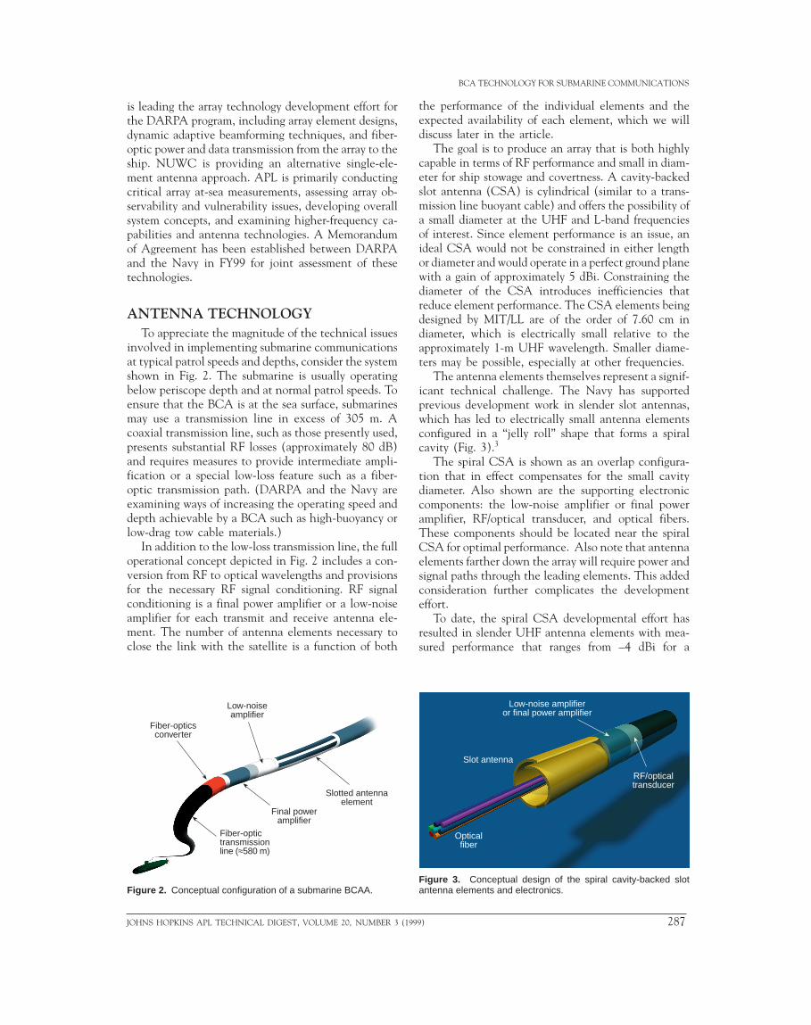
involved in implementing submarine communicationsat typical patrol speeds and depths, consider the systemshown in Fig. 2. The submarine is usually operatingbelow periscope depth and at normal patrol speeds. Toensure that the BCA is at the sea surface, submarinesmay use a transmission line in excess of 305 m. Acoaxial transmission line, such as those presently used,presents substantial RF losses (approximately 80 dB)and requires measures to provide intermediate ampli-fication or a special low-loss feature such as a fiber-optic transmission path. (DARPA and the Navy areexamining ways of increasing the operating speed anddepth achievable by a BCA such as high-buoyancy orlow-drag tow cable materials.)
In addition to the low-loss transmission line, the fulloperational concept depicted in Fig. 2 includes a con-version from RF to optical wavelengths and provisionsfor the necessary RF signal conditioning. RF signalconditioning is a final power amplifier or a low-noiseamplifier for each transmit and receive antenna ele-ment. The number of antenna elements necessary toclose the link with the satellite is a function of both
Low-noiseamplifier
Fiber-opticsconverter
Fiber-optictransmissionline (≈580 m)
Final poweramplifier
Slotted antennaelement
Figure 2. Conceptual configuration of a submarine BCAA.
JOHNS HOPKINS APL TECHNICAL DIGEST, VOLUME 20, NUMBER 3 (1
BCA TECHNOLOGY FOR SUBMARINE COMMUNICATIONS
the performance of the individual elements and theexpected availability of each element, which we willdiscuss later in the article.
The goal is to produce an array that is both highlycapable in terms of RF performance and small in diam-eter for ship stowage and covertness. A cavity-backedslot antenna (CSA) is cylindrical (similar to a trans-mission line buoyant cable) and offers the possibility ofa small diameter at the UHF and L-band frequenciesof interest. Since element performance is an issue, anideal CSA would not be constrained in either lengthor diameter and would operate in a perfect ground planewith a gain of approximately 5 dBi. Constraining thediameter of the CSA introduces inefficiencies thatreduce element performance. The CSA elements beingdesigned by MIT/LL are of the order of 7.60 cm indiameter, which is electrically small relative to theapproximately 1-m UHF wavelength. Smaller diame-ters may be possible, especially at other frequencies.
The antenna elements themselves represent a signif-icant technical challenge. The Navy has supportedprevious development work in slender slot antennas,which has led to electrically small antenna elementsconfigured in a “jelly roll” shape that forms a spiralcavity (Fig. 3).3
The spiral CSA is shown as an overlap configura-tion that in effect compensates for the small cavitydiameter. Also shown are the supporting electroniccomponents: the low-noise amplifier or final poweramplifier, RF/optical transducer, and optical fibers.These components should be located near the spiralCSA for optimal performance. Also note that antennaelements farther down the array will require power andsignal paths through the leading elements. This addedconsideration further complicates the developmenteffort.
To date, the spiral CSA developmental effort hasresulted in slender UHF antenna elements with mea-sured performance that ranges from –4 dBi for a
Low-noise amplifieror final power amplifier
Slot antenna
Opticalfiber
RF/opticaltransducer
Figure 3. Conceptual design of the spiral cavity-backed slotantenna elements and electronics.
999) 287

G. R. THOMPSON ET AL.
1.59-cm-diameter element to 0 dBi for both 2.54- and2.86-cm-diameter elements. Note that these antennaelements are linearly polarized, whereas the Navy’sUHF satellites are circularly polarized, which results inan added 3-dB signal mismatch loss (i.e., a net effectiveantenna element gain of –3 dB for the 2.54-cm-dia.element). As we will show later in the article, CSAelements operated in a linear array are believed to havesufficient performance to operate with the UHF Fol-low-on (UFO) satellite. Similar technology and designapproaches may be used for potential higher-frequency(e.g., L-band) elements.
ARRAY DYNAMICS AND WASHOVERThe degree of buoyancy in a floating antenna is
necessarily limited. Payload elements such as the actualantennas, the signal and power transmission lines, andelectronics assemblies are composed of metals, plastics,and glass; the modest diameters of the housings (1.7–7.6 cm) constrain the volume available for addedfloatation materials. The specific gravity of the flexiblebuoyant antenna designs under consideration rangesfrom 0.4 to 0.7. A floating wire antenna also has verysmall exposed height or “freeboard.” The largest cablesconsidered, even floating two-thirds out of the water,protrude barely 5.08 cm above the ocean surface, muchless than the wave heights associated with oceanicswells and comparable to the heights of locally createdwind waves.
The resulting interaction with both wind waves andswell causes washover and the deformation of the cable(departure of its shape from a straight line throughspace). Cable deformation occurs on a scale comparableto that of the swell; the antenna-phasing process mustaccount for this deformation to achieve the requiredantenna gain. Washovers are potentially more dam-aging to system performance since an element mustbe exposed, at least in part, to contribute to arrayperformance.
Knowledge of the detailed behavior of buoyant ar-rays on the ocean surface is limited. Global statistics,such as the average exposed and submerged fractionsand segment lengths for hundreds of meters of floatingwire for a test array, were obtained in 1981. Thesemeasurements were sufficient to characterize antennabehavior at current low frequencies. However, for theshort RF wavelengths encountered at UHF frequenciesand above, a more extensive understanding of thewashover behavior is required.
Figure 4 illustrates the behavior of a 1.7-cm buoyantcable test array under tow in a real seaway. The cablewas specially prepared with white bands molded in toenhance visibility and provide a distance scale. Thebands are 25.4 cm wide and spaced on 50.8-cm centers.Both the deformation and washover behaviors are very
288 JO
distinct. The sinuous shape shows some amount of de-formation. The very bright white stripes indicate cableregions that are above the water, whereas the sub-merged portions of the cable are indicated by the dis-tinctly darker (or absent) stripes. Although not easy tosee in Fig. 4, the small-diameter buoyant cable does notfloat exactly on the ocean surface, but assumes a shaperesembling an averaged version of the sea surface. Thebuoyant cable “rounds off” the extremes of the seasurface elevation, taking shortcuts through both thetroughs and crests of the waves.
To gain insights, a simulation was developed consist-ing of a moving ocean surface and a moving floatingcable responding to the buoyant forces exerted by that
Figure 4. Instrumented buoyant cable test array under tow. Thewhite bands, which were molded into the test antenna to enhancevisibility, are 25.4 cm wide and spaced on 50.8-cm centers.
HNS HOPKINS APL TECHNICAL DIGEST, VOLUME 20, NUMBER 3 (1999)

BCA TECHNOLOGY FOR SUBMARINE COMMUNICATIONS
surface. The simulated ocean surface was derived froma sophisticated, two-dimensional ocean wave spectrum;the floating cable’s response was modeled as a low-passfilter on the shape of the surface.4 The filter character-istics for the floating cable were chosen to match theaverage exposed and submerged fractions observedduring the test. The simulation, then, focused on float-ing cables with the same diameter (1.7 cm) and othercharacteristics. An extension to larger cable diametersis planned.
Figure 5 shows the simulation based on the test data.The cable is being towed to the right at 3 kt into a fullydeveloped sea with an 8.2-kt wind. The alternatingseries of exposed and submerged lengths is shown, as isthe position of the array relative to the sea surface. Notethat the exposed regions do not lie on the sea surface,but are suspended a short distance above it.
The buoyant cable in Fig. 5 shows hypothesized lo-cations of individual antenna elements within the ar-ray. The elements shown are 0.5 m long and are spacedat 1.5-m intervals, reasonable choices for a UHF sys-tem, with an RF wavelength of about 1.0 m. The keychallenge posed by washover to the system designer isillustrated by the condition of the 13 antenna elementsdepicted in Fig. 5: 5 are completely submerged andanother 2 are partially so, leaving only 6 available totransmit or receive at the instant shown. The arraydesigner then must choose a number of array elementsto build into the cable with the requirement that n ofthem contribute at any one time.
The required number of active elements n is deter-mined by the array gain needed in the RF link budget(discussed later), but the number of elements requiredin the array m is set by the washover characteristics.The relationship of m to n can be explored by runningthe simulation that produced Fig. 5 for an extendedperiod of time and tabulating the results. Figure 6 is amap of simulation output showing the exposure statusof each array element during a 3-s period.
The active elements are indexed horizontally in thefigure, and time goes from bottom to top. The gray scalevalue for each element and time shows the fraction ofthe 0.5-m length of the exposed element. Note that onlythe active elements (the dark bands of Fig. 5)are shown; the intervening parts of the cable are not
Figure 5. Simulation of a 1.7-cm array being towed through arough sea surface, which causes some elements to be exposedand others submerged. (Red portions of curve = wire, black =antenna elements.)
0
–0.2
–0.4
–0.635 40 45 50 55
Along-track range (m)
Ele
vatio
n (m
)
JOHNS HOPKINS APL TECHNICAL DIGEST, VOLUME 20, NUMBER 3 (1
represented in Fig. 6. Each element exposure (thevertical white bars) lasts about 1 s; the submerged in-tervals (vertical black bars) last somewhat longer. Atthe start of the interval, about 15 of the 50 elementsare completely exposed; the exposure status of the el-ements changes frequently, and at the end of the inter-val about 13 are completely exposed. All but a few ofthe 50 elements are completely exposed at some pointduring the interval, but no element is completely ex-posed for the entire interval. Thus, a receiver design fora BCA communications system must either be robustagainst such rapid changes or adapt to them.
Current BCA-sized designs for UHF communica-tions would require the gain from multiple antennaelements to satisfy the link budget. Therefore, statisticson the number of elements out of the water at any giventime are of great interest. If the simulation from Figs.5 and 6 is extended to an interval of several thousandseconds, the temporal statistics of the number of ex-posed elements can be tabulated. The result for theavailable antenna gain for a BCA-sized array with 50instrumented elements is shown in Fig. 7. The availableantenna array gain is related to the number of exposedelements by G = 10 log n, where G is the maximum gainavailable from the phased array, and n is the number ofelements exposed and participating in the array.
For this case, 9+ dB of array gain (8 or more elementsexposed) is available almost 99% of the time, and10+ dB (10 or more elements exposed) is available 95%of the time. Statistics such as these are used by thedesigner in folding the washover properties togetherwith the properties and requirements of the communi-cations system in order to select the number of elementsfor the aperture. Other statistics that can be computedon the basis of the simulation include fade duration(the average length of time that the gain spends belowa given threshold) and element statistics such as thedistribution of the duration of individual elementexposures and submergences.
3.0
2.5
2.0
1.5
1.0
0.5
0
Tim
e (s
)
0 10 20 504030Element number
1.0
0.8
0.2
0.4
0.6
0
Exp
osed
frac
tion
of th
e el
emen
t
Figure 6. Exposure map for the antenna elements of a 1.7-cm testarray towed at 3 kt away from an 8.2-kt wind sea. The gray scaleshows the fraction of each active element that is exposed.
999) 289

G. R. THOMPSON ET AL.
The simulation used in the previous description istied to 1.7-cm-diameter cables because it employedmeasurements of 1.7-cm test array behavior to set thecable’s response to the ocean surface. The biggest dif-ference between a 7.6- and a 1.7-cm cable is the addedfreeboard of the larger cable. This should lead to betterexposure characteristics for 7.6-cm-diameter cable ar-rays. Anecdotal evidence from very short data segmentstaken under the DARPA BCAA Program in 1998 sup-ports this observation. The trade-offs with larger diam-eters include ship impact and possible differences inobservability.
UHF SATELLITE COMMUNICATIONSMilitary UHF SATCOM relies principally on the
UFO satellite system as well as some legacy capabilityon the Fleet Satellite (FLTSAT) System. These systemshave three segments: space, ground or terminal, andcontrol.
The UFO space segment consists of eight satellitesin geosynchronous orbit above the equator, with twosatellites working simultaneously in one of fouroperational areas. Each UFO satellite has 39 UHFcommunications channels: 1 antijam uplink broadcastchannel, 17 wideband channels (25-kHz bandwidth),and 21 narrowband channels (5-kHz bandwidth). Eachwideband and narrowband channel uses a separate tran-sponder to receive, frequency translate, and amplifysignals within the channel. As such, these transpondersare often referred to as bent pipes.
The ground segment comprises fixed site, ship, sub-marine, aircraft, ground mobile, and man-portable ter-minals. Terminals consist of RF equipment (antennas,diplexers, low-noise amplifiers, power amplifiers, radiotransceivers) and baseband equipment (modems, cryp-tographic equipment, voice/data user equipment).
1.0
Pro
babi
lity
of g
ain
≥ ab
scis
sa
1.0
0.4
0.6
0.2
0.8
06 7 8 9 10 11 12 13 14
Instantaneous available BCA antenna gain (dB)
Figure 7. Distribution of available antenna gain due to washoverfor a 50-element 1.7-cm array in an 8.2-kt wind, downwind tow.
290 JO
The control segment consists of both satellite andcommunications control. Satellite control is providedby tracking, telemetry, and command subsystems thatare compatible with the Air Force Satellite ControlNetwork. Communications control is provided by theJoint (UHF) MILSATCOM Network Integrated (JMI-NI) Control System. JMINI implements demand-as-signed multiple-access (DAMA) operation, which al-lows one channel to support multiple communicationsrequirements simultaneously. This mode of operationalso allows satellite resources to be assigned to servicesaccording to a schedule (preassigned service) or basedon a request for service from a user (ad hoc service).When a communications service is no longer required,its resource is made available for another service.DAMA also allows preemption of one communicationsservice to support another higher-priority requirement.The DAMA mode of operation allows many morecommunications requirements to be satisfied than pos-sible using today’s methods by centrally controlling useraccess to the UHF MILSATCOM channels.
System Performance
The system performance of UHF SATCOM datalinks is quantified in a link budget. An example of alink budget for a seven-element BCAA is shown inTable 1. Here, it is assumed that a shore station issending data to the BCAA using a 25-kHz channel ona UFO satellite. The shore station is characterized byits effective isotropic radiated power (EIRP), whichincludes the terminal power amplifier, antenna gain,and various losses. The satellite is principally charac-terized by the receive gain-to-noise temperature ratio(G/T) and EIRP. However, the satellite produces twosecondary effects in the link budget; the use of a hard-limiter at the input to the transponder causes a 1.1-dBprocessing gain, and the use of right-hand circularpolarization causes a 3-dB mismatch with the linearlypolarized spiral CSA. The BCAA is characterized bythe peak element gain and gain derived from arrayingthese elements.
Once the characteristics of the individual elementsin a link budget are known, that satellite link is brokeninto its two components: uplink and downlink. Foreach component, carrier power-to-noise power density(C/N0) computations are made. These are simple ad-ditions and subtractions if all the elements are in deci-bels. The total C/N0 is then assessed by combining theuplink and downlink C/N0 quantities as
CN
CN
CN
.total uplink downlink0 0
1
0
11
=
+
− − −
HNS HOPKINS APL TECHNICAL DIGEST, VOLUME 20, NUMBER 3 (1999)

An important measure of performance for digitalcommunications is the probability of bit error PE. Asshown in Fig. 8, PE varies with energy per bit-to-noisepower density ratio (Eb/N0) and by modulation type.Recognizing that C/N0 is related to Eb/N0 byC/N0 = (Eb/N0)R, where R = 1/T (bit duration) or bitrate, we can relate the C/N0 derived in the link budgetto PE. Alternately, a PE can be specified, and theC/N0 that is available for communications as deter-mined by the link budget can be compared to theC/N0 that is required to support the particular data rateand modulation type. The difference between these twoC/N0 values can be considered margin.
As an example, consider Fig. 9, where the commu-nications scheme uses differential phase shift keying(DPSK) modulation and a 10–5 PE is adequate. Usingthe link budget already derived, we can see that thelink margin is 3.4 dB for a communications rate of24,000 bps.
Orientation and Washover EffectsThe link budget computed in Table 1 was made
under ideal conditions that assumed that the peakelement gain was oriented toward the satellite and thatthere were no communications channel degradations.Under operational conditions, element gain in thedirection of the satellite will be reduced relative to peak
Table 1. UHF satellite link budget.
Parameter Units
Shore station-to-satellite uplinkShore station EIRPa 26.8 dBWUplink propagation loss 2174.0 dBProcessing gain 1.1 dBBoltzmann’s constant21 228.6 dB/K/HzSatellite G/Tb 216.0 dB/KUplink C/N0
c 66.5 dBSatellite-to-BCAA downlinkSatellite EIRP (25 kHz) 26.0 dBWDownlink propagation loss 2173.0 dBNominal peak antenna element gain 20.9 dBiLPolarization mismatch 23.0 dBArray gain (10 log n) 8.5 dBNoise temperature of BCAA21 28.0 dBKBoltzmann’s constant21 228.6 dB/K/HzDownlink C/N0 58.2 dB
C/N0 total 57.5 dBaEIRP = effective isotropic radiated power.bG/T = gain-to-noise temperature ratio.cC/N0 = power-to-noise power density.
JOHNS HOPKINS APL TECHNICAL DIGEST, VOLUME 20, NUMBER 3 (19
BCA TECHNOLOGY FOR SUBMARINE COMMUNICATIONS
as angle varies from zenith and azimuth angle variesfrom broadside. Currently designed BCAA elementshave an approximately 3-dB orientation loss for oper-ational conditions where the angle from the horizon(elevation angle) is 10o and the angle from broadsideis 30o.
Communications channel degradations will resultfrom washover or other environmental effects. In thisregard, washover represents the biggest concern. As afirst-order approximation for communications model-ing, we will model the output of the BCAA beamform-er as a random variable. Power measurements madeduring at-sea testing will form a probability densityfunction for a given set of sea states and headings withrespect to the seas.
PE estimations of simple modulations can then bemade using simple continuous-wave (CW) measure-ments from the satellite:
P P E P dEC
NC
NC
N=
⌠
⌡
∞
00 0 0,
1 3 100
Pro
babi
lity
of b
it er
ror
1 3 10–2
1 3 10–4
1 3 10–6
1 3 10–8
0 2 4 6 8 10 12
Eb/N0 (dB)
Figure 8. Probability of bit error versus energy per bit-to-noisepower density (Eb/N0) for three transmission types: binary phaseshift keying (black curve), differentially coherent phase shift keying(red curve), and differential phase shift keying (blue curve).
Figure 9. Probability of bit error versus carrier power-to-noisepower density (C/N0) for three bit rates: R = 2,400 (black curve),9,000 (red curve), and 24,000 (blue curve) bps.
1 3 100
Pro
babi
lity
of b
it er
ror
1 3 10–2
1 3 10–4
1 3 10–6
1 3 10–8
40 45 50 55 6057.5
C/N0 (dB)
3.4-dBmargin
99) 291

G. R. THOMPSON ET AL.
where
P ECN0
is the PE given input C/N0, and P(C/N0) is the prob-ability density function of the measured power afteraccounting for the noise power density of the receivesystem. For DPSK modulation,
P E e RCN0
C
=
−
0 5 0. .N
Thus, for a given rate R and sea state conditions, PE canbe estimated.
This simple method has many limitations, however,the greatest being that the characterization must fullydescribe PE. Some modulations, such as coherent phaseshift keying, would arguably fail this criterion, since thephase reference will often be lost after an outage oflimited duration. Once this reference is lost, the newreference can lock incorrectly and subsequent bits willall be decoded erroneously.
Similarly, the method can not be simply extendedto include the effects of commonly used forward errorcontrol coding techniques such as Viterbi coding.Convolutional coding with Viterbi decoding is ideallysuited to an additive white Gaussian channel whereerrors occur randomly. Washover will cause burst oferrors that could easily exceed the error-correctingability of the code. It may be possible to model the bursterrors by accounting for the washover as a joint distri-bution that includes both fade depth and fade duration.
FY99 AT-SEA TESTINGFigure 10 depicts the FY99 DARPA test of BCA
experimental technologies, just completed in May–June 1999. The purpose of the test was to obtain side-by-side measurements from the MIT/LL BCAA and thesingle-element Low Profile Antenna (LPA) being de-veloped by NUWC. The test was performed in thewaters off the Pacific Missile Range Facility (PMRF) onthe island of Kauai.
The primary objectives of the test were to measureand compare the following key link budget parameters:
• Elevation loss as a function of elevation angle undera variety of environmental conditions. Elevation lossis governed by such factors as the interaction of theantenna pattern with the moving ocean surface, thepitch and yaw of the antenna elements as seen atlow grazing angles, and the increased effect of waterdroplets and water lapping at the lower angles closerto the ocean surface.
292 JOH
• Link margin and sustainable data rate using actualsatellite signals under a variety of environmentalconditions in a realistic open ocean environment.The UHF FLTSAT situated over the continentalUnited States will be used, with both CW and modu-lated waveforms. Variability in the environmentalconditions is to include sea state, headings with re-spect to the seas, and tow speeds that are as represen-tative as possible of expected operational conditions.
Secondary objectives included an initial, qualitativeassessment of the observability of the two systems, pri-marily by visual and infrared means; the collection ofdata to characterize statistically element washover andantenna availability; and the collection of data to allowextrapolations of the expected performance of variantsand hybrids of the two systems. As indicated in Fig. 10,video and IR measurements were conducted from ahelicopter and from a high-resolution automated track-ing camera on shore.
The PMRF was selected because of the 457-m-cliffsite on Makaha Ridge on the western shore of Kauai,which provides an unobstructed path from the shore-based UHF transmitter to the antennas being towed inthe waters below at relatively steep elevation angles ofup to 30°. Measurements from the FLTSAT were con-ducted in open ocean waters in the PMRF locale.Predominantly receive-only testing was done; side-by-side testing was performed so that simultaneous mea-surements could be obtained from both experimentalsystems under the same operational conditions, andso that the performance of the two experimental tech-niques could be compared using like measures ofperformance. Port and starboard outriggers were in-stalled for simultaneous side-by-side testing of bothsystems.
Environmental CharacterizationAn accurate assessment of the environment was key
because the performance of the systems was expectedto be highly dependent on factors such as sea state,significant wave height, and the direction of tow withrespect to the seas. Environmental data were collectedby two principal systems: a directional wave buoy anda scientific-grade meteorological system. The wavebuoy is a deployed system that collects directional wavespectral data while in the water, and continually trans-mits these data to the ship via an RF link. The direc-tional wave spectral data will allow an accurate assess-ment of sea state and significant wave height by use ofthe Wave Identification and Tracking System (WITS)5
onboard the US NohoLoa to analyze each 0.5-h seg-ment of data. The meteorological system provided windspeed and direction, air and sea surface temperature,relative humidity, and barometric pressure. The windspeed data will allow an alternate assessment of sea
NS HOPKINS APL TECHNICAL DIGEST, VOLUME 20, NUMBER 3 (1999)

BCA TECHNOLOGY FOR SUBMARINE COMMUNICATIONS
Pacific MissileRange Facility
Test uplinksignals (Naval Undersea
Warfare Center)
Continental U.S. satellite
Alternative openocean test siteHigh-resolutioncamera
Cliff-siteradiated test
signals UHF link budgettesting and validation
(receive mode)
30°
20°
10°
UHF/SATCOM transmissions(R/D and other channels)
Visual/IRmeasurements
Referenceantenna
Testvans
Wave buoys
Office of Naval Research towed low-profile
antennaDARPA multi-element
array
Elevation loss testing(10 to 30°)
Figure 10. An overview of the DARPA BCA technology test, showing both the elevation loss and UHF link budget test componentsconducted in Hawaii during May and June 1999.
state. Additionally, photographs taken every 30 minwill provide a visual record of the sea state.
Test Matrix and Run DescriptionA fundamental objective of the test was to measure
elevation loss and link margin under a variety of con-ditions expected to span the range of actual submarineoperating conditions for the communications system.Table 2 lists the conditions under which measurementswere to be made, both for the elevation loss and linkmargin components of the test. The principal param-eters to be varied were:
• Antenna tow heading with respect to the direction ofthe dominant wave component of the seas
• Elevation angle from the antenna to the satellite(or ridge) transmitter
• Sea state• Tow speed of the antennas through the water• Angle to the transmitter relative to the antenna
broadside
JOHNS HOPKINS APL TECHNICAL DIGEST, VOLUME 20, NUMBER 3 (19
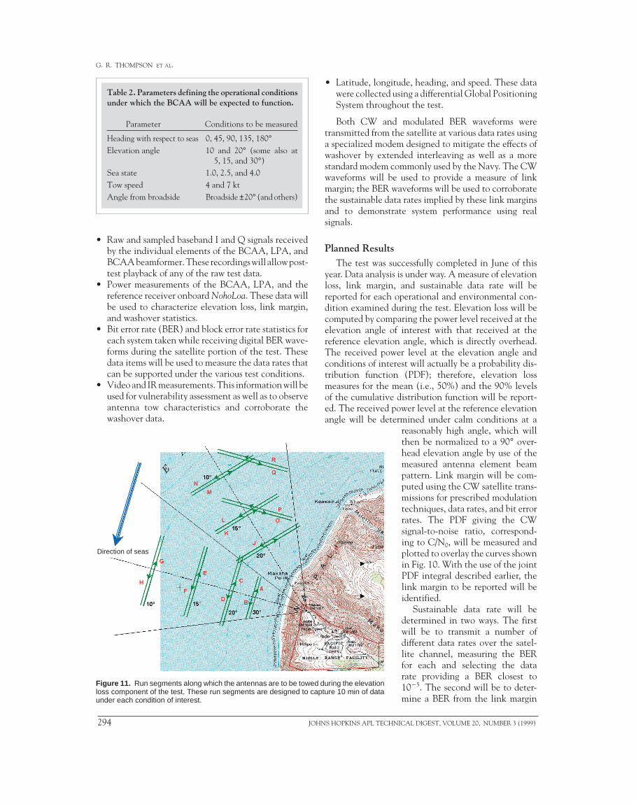
Figure 11 then shows a subset of the runs for theelevation loss testing, illustrating the differing eleva-tion angles from the shore, orientation to the seas, anddiffering reception angles. The BCA elements havea very significant falloff in gain as the angle incidentto the antenna progresses away from broadside. Mostof the testing was conducted near broadside, and mostof the results normalized to broadside so that meaning-ful, well-characterized comparisons could be madeacross the other parameters in the test matrix. How-ever, some data were collected at angles of up to 50°from broadside to obtain a good, albeit less complete,performance characterization under those conditions.Runs were conducted over multiple days to capture thedifferent sea state/swell combinations of interest.
Measurement OverviewThe test measured the following significant data in
addition to various environmental parameters alreadydescribed.
99) 293
G. R. THOMPSON ET AL.
Table 2. Parameters defining the operational conditionsunder which the BCAA will be expected to function.
Parameter Conditions to be measured
Heading with respect to seas 0, 45, 90, 135, 180°Elevation angle 10 and 20° (some also at
5, 15, and 30°)Sea state 1.0, 2.5, and 4.0Tow speed 4 and 7 ktAngle from broadside Broadside ±20° (and others)
• Raw and sampled baseband I and Q signals receivedby the individual elements of the BCAA, LPA, andBCAA beamformer. These recordings will allow post-test playback of any of the raw test data.
• Power measurements of the BCAA, LPA, and thereference receiver onboard NohoLoa. These data willbe used to characterize elevation loss, link margin,and washover statistics.
• Bit error rate (BER) and block error rate statistics foreach system taken while receiving digital BER wave-forms during the satellite portion of the test. Thesedata items will be used to measure the data rates thatcan be supported under the various test conditions.
• Video and IR measurements. This information will beused for vulnerability assessment as well as to observeantenna tow characteristics and corroborate thewashover data.
Figure 11. Run segments along which the antennas are to be towed during the elevationloss component of the test. These run segments are designed to capture 10 min of dataunder each condition of interest.
Direction of seas
294 JOHN
• Latitude, longitude, heading, and speed. These datawere collected using a differential Global PositioningSystem throughout the test.
Both CW and modulated BER waveforms weretransmitted from the satellite at various data rates usinga specialized modem designed to mitigate the effects ofwashover by extended interleaving as well as a morestandard modem commonly used by the Navy. The CWwaveforms will be used to provide a measure of linkmargin; the BER waveforms will be used to corroboratethe sustainable data rates implied by these link marginsand to demonstrate system performance using realsignals.
Planned ResultsThe test was successfully completed in June of this
year. Data analysis is under way. A measure of elevationloss, link margin, and sustainable data rate will bereported for each operational and environmental con-dition examined during the test. Elevation loss will becomputed by comparing the power level received at theelevation angle of interest with that received at thereference elevation angle, which is directly overhead.The received power level at the elevation angle andconditions of interest will actually be a probability dis-tribution function (PDF); therefore, elevation lossmeasures for the mean (i.e., 50%) and the 90% levelsof the cumulative distribution function will be report-ed. The received power level at the reference elevationangle will be determined under calm conditions at a
S HOPKINS APL TECH
reasonably high angle, which willthen be normalized to a 90° over-head elevation angle by use of themeasured antenna element beampattern. Link margin will be com-puted using the CW satellite trans-missions for prescribed modulationtechniques, data rates, and bit errorrates. The PDF giving the CWsignal-to-noise ratio, correspond-ing to C/N0, will be measured andplotted to overlay the curves shownin Fig. 10. With the use of the jointPDF integral described earlier, thelink margin to be reported will beidentified.
Sustainable data rate will bedetermined in two ways. The firstwill be to transmit a number ofdifferent data rates over the satel-lite channel, measuring the BERfor each and selecting the datarate providing a BER closest to1025. The second will be to deter-mine a BER from the link margin
NICAL DIGEST, VOLUME 20, NUMBER 3 (1999)

measurement by using curves such as those shown inFig. 10. This will be accomplished by specifying aminimum acceptable link margin and then selectingthe data rate curve that satisfies the link margin. Thesetwo measures of sustainable data rate will both be re-ported and are expected to agree fairly closely.
SUMMARYDARPA and the Navy are pursuing advanced BCA
technologies that could dramatically enhance subma-rine connectivity at speed and depth and overcomecurrent constraints that require periscope depth andmore exposed operations. Significant technical chal-lenges exist, which are being examined by DARPA andthe Navy, with a major joint field test of candidate
JOHNS HOPKINS APL TECHNICAL DIGEST, VOLUME 20, NUMBER 3 (19
BCA TECHNOLOGY FOR SUBMARINE COMMUNICATIONS
technologies just completed in FY99. APL is assistingboth DARPA and the Navy in the development, test-ing, and evaluation of this potentially important tech-nology to the submarine force.
REFERENCES1Joint Vision 2010, America’s Military Preparing for Tomorrow…., Chairman ofthe Joint Chiefs of Staff, available at http://131.84.1.34/doctrine/jv2010/jvpub.htm (accessed 20 May 1999).
2Clemens, A. (Adm.), Technology for the 21st Century, U.S. Naval Institute,Annapolis, MD (1998).
3Lee, J. C., “A Slender Resonator-Slot UHF Antenna,” in Proc. Second Int.Conf. on Antennas and Magnetics (1981).
4Apel, J. R., “An Improved Model of the Ocean Surface Wave VectorSpectrum and Its Effects on Radar Backscatter,” J. Geophys. Res. 99, 16,269–16,291 (Mar 1994).
5Hanson, J., “Wave Spectral Partitioning Applied to the Analysis of ComplexWave Conditions in the North Pacific Ocean,” in Proc. 8th Conf. on Air/SeaInteraction, pp. 61–65 (28 Jan 1996).
THE AUTHORS
G. RICHARD THOMPSON is a member of the APL Principal Professional Staffand a submarine technology specialist in the Submarine Technology Department(STD). He received a bachelor’s degree in electrical engineering from theGeorgia Institute of Technology in 1996, a master’s degree in systems analysisfrom George Washington University in 1975, and a master’s degree in technicalmanagement (with honors) from JHU in 1985. Mr. Thompson joined APL in1966 and has worked on the evaluation of SSBN navigational systems, served asthe Laboratory’s on-site representative at COMSUBPAC for the SSBN SecurityProgram, led the SSBN Tactical Development Program, and acted as ProgramManager for the DARPA Advanced Submarine Technology Program and theSSN Security Program. He is now on the staff of the Head of STD, supportinga number of Navy and DARPA submarine-related programs. His e-mail addressis [email protected].
HANS P. WIDMER is a member of the APL Principal Professional Staff in theSubmarine Technology Department (STD). He received a B.S. in electricalengineering from Concordia University, Montreal, in 1978, an M.S. in technicalmanagement from JHU in 1986, and is currently completing an M.S. inbiomedical engineering, also at JHU. From 1978 through 1986, Mr. Widmer wasinvolved in the prediction of electromagnetic interference between avionicssystems on military aircraft, for which he helped develop a computer model basedon the geometric theory of diffraction. He joined STD in 1986, and shortlythereafter became Project Manager for the LFAIR development effort. From1991 through 1998 he led the Total Ship Monitor System development effort,which has become the primary noise control system for the Seawolf and NSSNclass submarines. Since joining APL, Mr. Widmer has been actively involved infielding state-of-the-art technology in numerous at-sea experiments. His e-mailaddress is [email protected].
99) 295

G. R. THOMPSON ET AL.
296 JOHNS HOPKINS APL TECHNICAL DIGEST, VOLUME 20, NUMBER 3 (1999)
JOHN H. SWEENEY is a member of the APL Principal Professional Staff anda physicist in the Acoustics and Electromagnetics Group of the SubmarineTechnology Department. He received a B.S. in physics from the MassachusettsInstitute of Technology in 1973 and studied physics at the PennsylvaniaState University before joining APL in 1980. Mr. Sweeney has principallyworked in ocean acoustics, including long towed array beam noise, low-frequencypropagation, signal detection for low-frequency active sonars, the characteristicsof reverberation in low-frequency active sonars, and the planning and conductof large-scale at-sea experiments. He served as Test Scientist for severallong towed array experiments, including Critical Sea Test 1 (1988), CriticalSea Test 4 (1990), and SURTASS 3X-92 (1992). His e-mail address [email protected].
ROBERT E. BALL is a Senior Staff Systems Engineer in APL’s Strategic SystemsDepartment. He has an extensive background in systems and electricalengineering, especially in submarine communications systems. Recently, Mr. Ballmanaged the Diver Communications System Project, worked on an SOF combatdiver situation awareness tool, and led the development and implementation ofthe stabilized pointing submarine RF subsystem used in the SSN/MAE (Predator)interoperability demonstration. He is the Principal Investigator of two submarinecommunications IR&D projects: the Thin-Line Buoyant Cable Antenna and theSmall High Performance Antenna Systems for Special Purpose SubmarineConnectivity. Mr. Ball is also experienced in instrumentation systems develop-ment and integration as well as oceanographic optical imaging and sensing. Hise-mail address is [email protected].
KURT A. RICE is a section supervisor in the Satellite Communications Groupof APL’s Power Projection Systems Department. He received a B.S.E.E. fromDrexel University in 1983 and an M.S.E.E. from The Johns Hopkins Universityin 1987. He joined APL in 1983, working initially in the CommunicationsSystems Engineering Group, where he performed the modeling, simulation, andanalyses of U.S. strategic communications systems. Since 1988, Mr. Rice hasworked in a systems engineering capacity on Army and Navy satellitecommunications systems. Most recently, he has been performing systemsengineering and analysis toward the use of a UHF satellite data link for theTomahawk cruise missile as well as systems engineering for the Tactical ControlSystem used to control unmanned aerial vehicles. His e-mail address [email protected].


![Patch Antenna[1]](https://static.fdokumen.com/doc/165x107/63158e4cc32ab5e46f0d5c89/patch-antenna1.jpg)