
Header - Amphenol Antenna Solutions
41
-
Upload
khangminh22 -
Category
Documents
-
view
2 -
download
0
Transcript of Header - Amphenol Antenna Solutions


Header
ALDC_SW_UM ©2011 Amphenol Antenna Systems | www.amphenol-antennas.com Page 1 of 41
Contents 1. Introduction ........................................................................................................................................................................................ 2 Product Functions ................................................................................................................................................................................. 2
SmartTilt Technology .......................................................................................................................................................................... 3 2. ALDC Software Installation Setup ................................................................................................................................................... 4
Setup Preparation ............................................................................................................................................................................... 4 Downloading ALDC Software ............................................................................................................................................................. 5 Extracting ALDC Software .................................................................................................................................................................. 7 Installing ALDC Software .................................................................................................................................................................... 7
3. Launching the ALDC System Software ........................................................................................................................................... 9 4. System Configuration ..................................................................................................................................................................... 10
System Settings ................................................................................................................................................................................ 10 Changing System Settings ................................................................................................................................................................ 10
Adapter Settings .................................................................................................................................................................................. 11 Changing Adapter Settings ............................................................................................................................................................... 11 Changing Adapter Settings, cont. ..................................................................................................................................................... 12
5. Using the ALDC System Software ................................................................................................................................................. 13 Device Scan ...................................................................................................................................................................................... 13 Add a Device ..................................................................................................................................................................................... 16 Refresh .............................................................................................................................................................................................. 17 Tool Bar Commands ......................................................................................................................................................................... 17 RET Detail Settings ........................................................................................................................................................................... 20 Uploading a New Configuration File to a RET .................................................................................................................................. 21 Changing the Frequency Band ......................................................................................................................................................... 22 Set Tilt ............................................................................................................................................................................................... 23 Get Tilt ............................................................................................................................................................................................... 23 Calibration ......................................................................................................................................................................................... 24 Download Software—RET and TMA ................................................................................................................................................ 25 TMA Detail Settings .......................................................................................................................................................................... 26 Antenna Installation Data (See “Antenna Installation Data”) ............................................................................................................ 26 Antenna Model Data (See “Antenna Model Data”) ........................................................................................................................... 26 TMA Model Data ............................................................................................................................................................................... 27 Set Mode ........................................................................................................................................................................................... 27 Get Mode .......................................................................................................................................................................................... 28 Set Gain ............................................................................................................................................................................................ 28 Get Gain ............................................................................................................................................................................................ 28 Site Report ........................................................................................................................................................................................ 29 Antenna Model Management ............................................................................................................................................................ 30 Add a Vendor .................................................................................................................................................................................... 31 AISG Vendor Codes: ........................................................................................................................................................................ 32 Delete a Vendor ................................................................................................................................................................................ 33 Add an Antenna Model ..................................................................................................................................................................... 33 Delete an Antenna Model ................................................................................................................................................................. 33
Appendix A: Changing AISG Communications Mode ..................................................................................................................... 34 Switching Between Communication Modes ...................................................................................................................................... 34
Appendix B: Remote Azimuth Steering (RAS) .................................................................................................................................. 35 Overview ........................................................................................................................................................................................... 35 RAS Device Setup ............................................................................................................................................................................ 36 The Antenna Azimuth Setting ........................................................................................................................................................... 37

Heading 1
ALDC_SW_UM ©2011 Amphenol Antenna Systems | www.amphenol-antennas.com Page 2 of 41
1. Introduction The Antenna Line Device Control (ALDC) system is a portable primary controller used for configuration and control of AISG v1.1 and/or AISG v2.0 devices at a cell site. The system consists of a Portable Control Unit (PCU), data cables, a 24v power supply and ALDC software, which is installed on a user’s laptop computer. This system is an upgrade to Amphenol Antenna Solutions’ previous PCU-2 system that was only able to control AISG v1.1 devices.
Hardware Software Serial Interface AISG Version
PCU-2 (previous version) ALDC v1.x RS232 serial port AISG v1.1 (only)
PCU-4 ALDC v2.x USB 1.1 or 2.0 AISG v1.1 or v2.0
Product Functions The major functions provided in the ALDC system include:
Antenna Remote Electrical Tilt/Remote Azimuth Steering Adjustment • Antenna electrical tilt setting
• Antenna azimuth steering setting
• Antenna self-test and reset
• Antenna installation data maintenance
• Antenna model management
• Software Download
AISG TMA Adjustment • TMA gain setting
• TMA mode setting
• TMA self-test and reset
• TMA installation data maintenance
• Software Download
Device Calibration
Device Configuration
Heading 1
ALDC_SW_UM ©2011 Amphenol Antenna Systems | www.amphenol-antennas.com Page 3 of 41
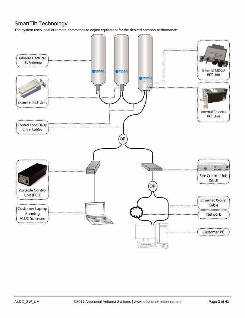
SmartTilt Technology The system uses local or remote commands to adjust equipment for the desired antenna performance.
Heading 1
ALDC_SW_UM ©2011 Amphenol Antenna Systems | www.amphenol-antennas.com Page 4 of 41
2. ALDC Software Installation Setup Setting up the ADLC software involves three steps: downloading, extracting, and then installing.
Setup Preparation Make sure prior to setup that the ADLC system you received includes the following:
• Portable Control Unit (PCU-4)
• USB Data Cable
• AISG Control Cable
• 24V Power Supply
• ALDC software v2.0 for Microsoft Windows. The best way to obtain the latest software is to download it from the Amphenol Antennas Web site.
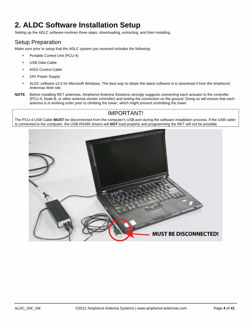
NOTE Before installing RET antennas, Amphenol Antenna Solutions strongly suggests connecting each actuator to the controller (PCU-4, Node B, or other antenna vendor controller) and testing the connection on the ground. Doing so will ensure that each antenna is in working order prior to climbing the tower, which might prevent reclimbing the tower.
IMPORTANT! The PCU-4 USB Cable MUST be disconnected from the computer’s USB port during the software installation process. If the USB cable is connected to the computer, the USB-RS485 drivers will NOT load properly and programming the RET will not be possible.
Heading 1
ALDC_SW_UM ©2011 Amphenol Antenna Systems | www.amphenol-antennas.com Page 5 of 41
Downloading ALDC Software Downloading ALDC Software from CD Not all users have the CD; if you are missing the CD skip this section. Instead refer to “Downloading ALDC Software from the Internet (Windows XP)” or “Downloading ALDC Software from the Internet (Windows 7)”, determining which operating system you are using.
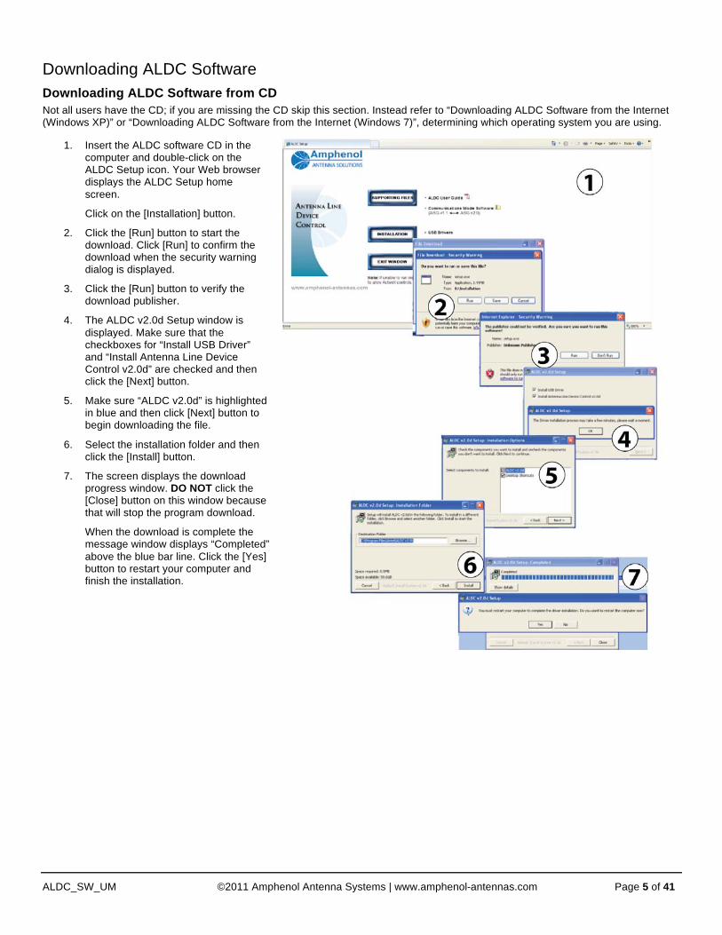
1. Insert the ALDC software CD in the computer and double-click on the ALDC Setup icon. Your Web browser displays the ALDC Setup home screen.
Click on the [Installation] button.
2. Click the [Run] button to start the download. Click [Run] to confirm the download when the security warning dialog is displayed.
3. Click the [Run] button to verify the download publisher.
4. The ALDC v2.0d Setup window is displayed. Make sure that the checkboxes for “Install USB Driver” and “Install Antenna Line Device Control v2.0d” are checked and then click the [Next] button.
5. Make sure “ALDC v2.0d” is highlighted in blue and then click [Next] button to begin downloading the file.
6. Select the installation folder and then click the [Install] button.
7. The screen displays the download progress window. DO NOT click the [Close] button on this window because that will stop the program download.
When the download is complete the message window displays “Completed” above the blue bar line. Click the [Yes] button to restart your computer and finish the installation.

Heading 1
ALDC_SW_UM ©2011 Amphenol Antenna Systems | www.amphenol-antennas.com Page 6 of 41
Downloading ALDC Software from the Internet
1. On the control computer, open a Web browser (Internet Explorer recommended) and go to the Amphenol Antenna Web site (http://www.amphenol-antennas.com). The Web browser screen displays the Amphenol Antennas home page.
2. Select Products—>RET Control Systems—>RET System Software Downloads from the Products pull-down selection list. The Web browser opens the RET System Software Downloads page.
3. The RET System Software Downloads page displays links to software files that can be downloaded. Click on the link SmartTilt Antenna Line Device Control (ALDC) Software for PCU-KIT-4-xx.
4. This opens a file download prompt. Click the Save button.
NOTE Windows 7 (4a) and Windows XP (4b) download prompts are slightly different in appearance.
5. Select your PC desktop as the target download location. The screen will display the download status, and when completed the file ALDCv2-0d-.zip is on your computer.
6. When the download is complete, click on the Open button.

Heading 1
ALDC_SW_UM ©2011 Amphenol Antenna Systems | www.amphenol-antennas.com Page 7 of 41
Extracting ALDC Software 1. Click on the file Amphenol Antenna
Solutions ALDC 2.0 for PCU-4.zip. The screen displays the Extraction Wizard tool. Click the [Next] button to extract the files.
2. Click the [Finish] button. All of the files you need to install the ALDC software have been extracted into the target directory on your PC.
3. The target directory displays the folder Antenna Line Device Control Software (ALDC) v2.0 for PCU-4.
Installing ALDC Software Installing ALDC Software (Windows XP)
1. Double-click on the folder Antenna Line Device Control Software (ALDC) v2.0 for PCU-4. The folder contains an autorun utility and the Installation folder.
2. Double-click the Installation folder to open it, then double-click on the Setup icon to start the ALDC v2.0 Setup tool.
3. Leave both installation options checked, and click the [Next] button. When the installation is complete your PC desktop displays the software icons, and it alerts you that the USB driver has been installed.

Heading 1
ALDC_SW_UM ©2011 Amphenol Antenna Systems | www.amphenol-antennas.com Page 8 of 41
Installing ALDC Software (Windows 7)
1. Double-click on the folder Antenna Line Device Control Software (ALDC) v2.0 for PCU-4. The folder contains an autorun utility and the Installation folder.
2. Double-click the Installation folder to open it, and then double-click on the Setup icon to start the ALDC v2.0 Setup tool. A confirmation window will appear. Click [Run], which will cause a new window to appear.
3. Leave both installation options checked and click the Next button. DO NOT click the [Close] button on this window while the installation is in progress, because that will interrupt the installation. When the installation is complete your PC desktop displays the software icons and alerts you that the USB driver has been installed.
4. Now, plug the USB connector from the PCU-4 into one of your computers USB ports. If your speaker(s) are enabled, you should hear an audible tone after the PCU-4 connects.
5. Click on the ALDC icon on the desktop to start the application. The screen displays the ALDC home screen.
6. Check the Port: COM number at the bottom of the home screen. Any number other than zero (0) means the USB cable is connected and detected by the system.
Heading 1
ALDC_SW_UM ©2011 Amphenol Antenna Systems | www.amphenol-antennas.com Page 9 of 41
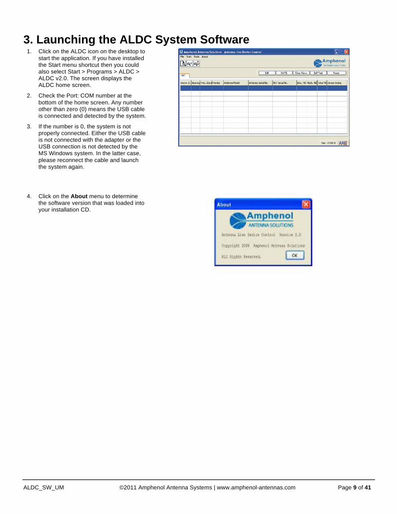
3. Launching the ALDC System Software 1. Click on the ALDC icon on the desktop to
start the application. If you have installed the Start menu shortcut then you could also select Start > Programs > ALDC > ALDC v2.0. The screen displays the ALDC home screen.
2. Check the Port: COM number at the bottom of the home screen. Any number other than zero (0) means the USB cable is connected and detected by the system.
3. If the number is 0, the system is not properly connected. Either the USB cable is not connected with the adapter or the USB connection is not detected by the MS Windows system. In the latter case, please reconnect the cable and launch the system again.
4. Click on the About menu to determine
the software version that was loaded into your installation CD.

Heading 1
ALDC_SW_UM ©2011 Amphenol Antenna Systems | www.amphenol-antennas.com Page 10 of 41
4. System Configuration This section contains information about changing the system and adapter settings.
System Settings The system settings determine how many bit-mask bytes will be used to scan the device and whether the scanning process will automatically assign bus addresses to devices found during a scan operation.
The default setting is [scan length] = 3
The scanning process will automatically assign bus addresses to the connected AISG devices.
A user will rarely need to change these default settings.
Changing System Settings 1. Select [Tools] from the menu.
2. Select [System Setting] from the Tools menu.
3. Decide whether to mark [Scan without Changing Address] and/or change the Scan Length value.
Scan without Changing Address
Changing Scan Length Value
Purpose: Used to preserve the bus address of an AISG 1.1 device for trouble shooting.
Purpose: Used to set the number of digits in the device serial number (from the far right) that the scan routine looks at during a scan operation.
NOT an applicable setting for the AISG 2 device.
MUST INCREASE the [Scan Length] value if multiple devices have serial numbers with the same last three far right digits.
NOTE This WILL increase the time required to complete a scan.
By not checking the box, the system will automatically assign bus addresses to devices found during a scan operation.
The default setting is three digits.
By leaving it on the default setting, you will reduce the time needed to complete the scan.
Heading 1
ALDC_SW_UM ©2011 Amphenol Antenna Systems | www.amphenol-antennas.com Page 11 of 41
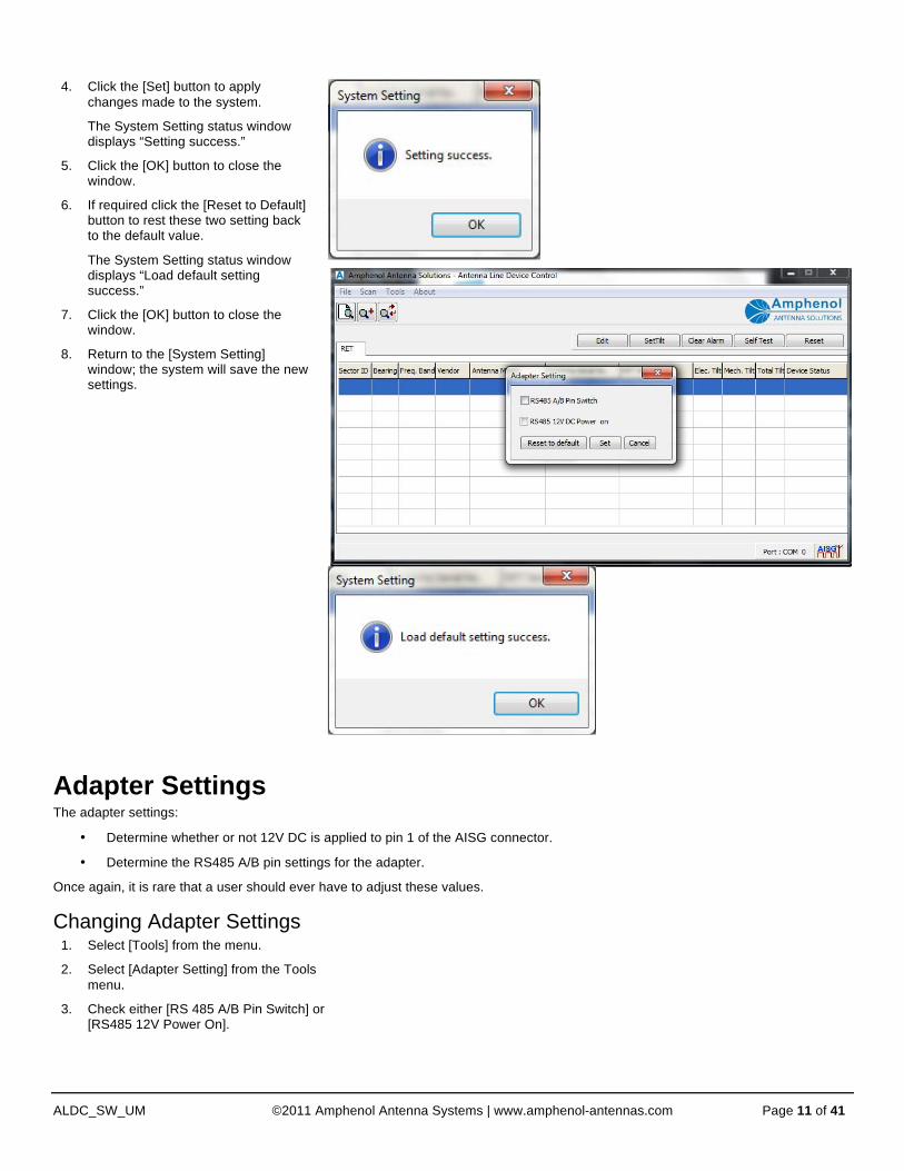
4. Click the [Set] button to apply changes made to the system.
The System Setting status window displays “Setting success.”
5. Click the [OK] button to close the window.
6. If required click the [Reset to Default] button to rest these two setting back to the default value.
The System Setting status window displays “Load default setting success.”
7. Click the [OK] button to close the window.
8. Return to the [System Setting] window; the system will save the new settings.
Adapter Settings The adapter settings:
• Determine whether or not 12V DC is applied to pin 1 of the AISG connector.
• Determine the RS485 A/B pin settings for the adapter.
Once again, it is rare that a user should ever have to adjust these values.
Changing Adapter Settings 1. Select [Tools] from the menu.
2. Select [Adapter Setting] from the Tools menu.
3. Check either [RS 485 A/B Pin Switch] or [RS485 12V Power On].
Heading 1
ALDC_SW_UM ©2011 Amphenol Antenna Systems | www.amphenol-antennas.com Page 12 of 41
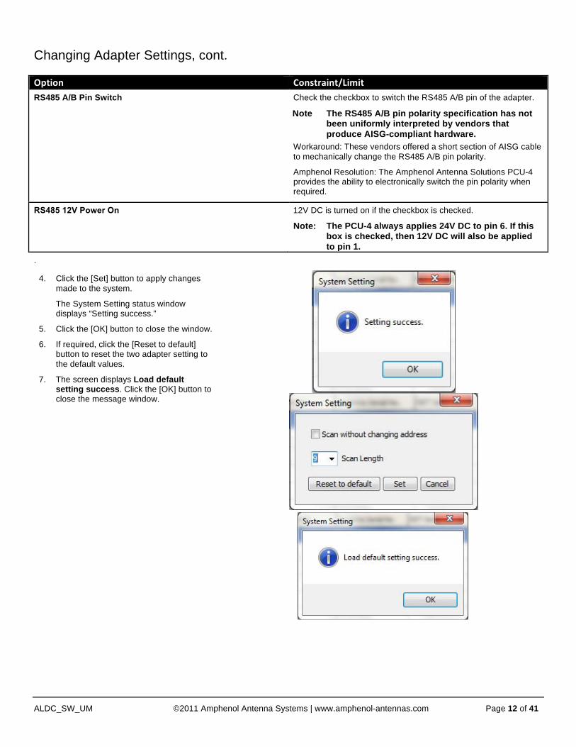
Changing Adapter Settings, cont. Option Constraint/Limit RS485 A/B Pin Switch Check the checkbox to switch the RS485 A/B pin of the adapter.
Note The RS485 A/B pin polarity specification has not been uniformly interpreted by vendors that produce AISG-compliant hardware.
Workaround: These vendors offered a short section of AISG cable to mechanically change the RS485 A/B pin polarity.
Amphenol Resolution: The Amphenol Antenna Solutions PCU-4 provides the ability to electronically switch the pin polarity when required.
RS485 12V Power On 12V DC is turned on if the checkbox is checked.
Note: The PCU-4 always applies 24V DC to pin 6. If this box is checked, then 12V DC will also be applied to pin 1.
.
4. Click the [Set] button to apply changes made to the system.
The System Setting status window displays “Setting success.”
5. Click the [OK] button to close the window.
6. If required, click the [Reset to default] button to reset the two adapter setting to the default values.
7. The screen displays Load default setting success. Click the [OK] button to close the message window.
Heading 1
ALDC_SW_UM ©2011 Amphenol Antenna Systems | www.amphenol-antennas.com Page 13 of 41
5. Using the ALDC System Software
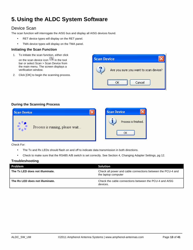
Device Scan The scan function will interrogate the AISG bus and display all AISG devices found.
• RET device types will display on the RET panel.
• TMA device types will display on the TMA panel.
Initiating the Scan Function
1. To initiate the scan function, either click
on the scan device icon in the tool bar or select Scan > Scan Device from the main menu. The screen displays a verification window.
2. Click [OK] to begin the scanning process.
During the Scanning Process
Check For:
• The Tx and Rx LEDs should flash on and off to indicate data transmission in both directions.
• Check to make sure that the RS485 A/B switch is set correctly. See Section 4, Changing Adapter Settings, pg 12.
Troubleshooting
Problem Solution The Tx LED does not illuminate. Check all power and cable connections between the PCU-4 and
the laptop computer
The Rx LED does not illuminate. Check the cable connections between the PCU-4 and AISG devices.

Heading 1
ALDC_SW_UM ©2011 Amphenol Antenna Systems | www.amphenol-antennas.com Page 14 of 41
Scan Results—RET
• The ALDC device status window displays all found RET devices.
• RET devices are automatically sorted by Sector ID.
Device Name Description/Constraint
Sector ID Sector ID
Bearing Antenna bearing in the range of 0-359 degrees
Freq. Band Current applied frequency band(s)
Vendor Vendor Name
Antenna Model Antenna model name
Antenna Serial No. Antenna serial number
RET Serial No. AISG RET device serial number
Elec. Tilt Current electrical tilt value
Mech. Tilt Current mechanical tilt value
Total Tilt Sum of mechanical tilt and electrical tilt
Device Status “OK” or device alarm messages

Heading 1
ALDC_SW_UM ©2011 Amphenol Antenna Systems | www.amphenol-antennas.com Page 15 of 41
Scan Results—TMA
• The ALDC device status window displays all found TMA devices.
• TMA devices are automatically sorted by Sector ID.
Column Name Description/Constraint
Sector ID Sector ID
Freq. Band Current applied frequency band(s)
Vendor Vendor name
Antenna Model Antenna model name
Antenna Serial No. Antenna serial number
TMA Model TMA model name
TMA Serial No. TMA serial number
Current Gain Current gain value
Mode TMA gain mode: “Bypass” or “Normal”
Device Status “OK” or device alarm messages
Sector ID Sector ID

Heading 1
ALDC_SW_UM ©2011 Amphenol Antenna Systems | www.amphenol-antennas.com Page 16 of 41
Add a Device The Add a Device function is used to add a specific AISG device to the ALDC display list if that device cannot be found through the normal scan process.
Initiating the Add a Device Function
1. Click on the scan device icon in the tool bar, or select Scan > Add Device from the main menu. The screen displays the Add Device dialog box.
2. Enter the Serial Number of the device you would like to add. NOTE: This field is case sensitive! For more about the device Serial Number, see the Additional Information section below.
3. Enter the Vendor Code if desired—this field is optional.
4. Click the [Add] button to add the device to the ALDC display list. The screen displays a process window until the process is finished.
5. Click the [OK] button to close the message window. The ALDC display list has just been updated with this device.
Additional Information about the Serial Number
According to the AISG standard, each device must be assigned a unique identification number. “Unique ID Number” is defined as the vendor code followed by a device serial number. Amphenol Antenna Solutions displays one of two “Unique IDs” on each RET product shipped. This code can either be:
• JB (for Jaybeam Wireless) • Al (for Amphenol Antenna Solutions)
Example: Jaybeam Wireless Antenna
• Unique ID = JB/RETEH/080508/114
• Vendor Code = JB
• Serial Code = /RETEH/080508/114
Heading 1
ALDC_SW_UM ©2011 Amphenol Antenna Systems | www.amphenol-antennas.com Page 17 of 41
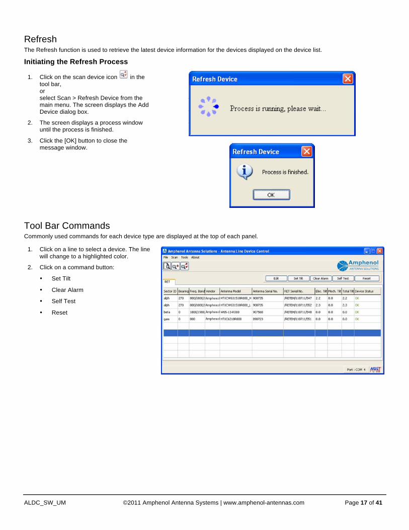
Refresh The Refresh function is used to retrieve the latest device information for the devices displayed on the device list.
Initiating the Refresh Process
1. Click on the scan device icon in the tool bar, or select Scan > Refresh Device from the main menu. The screen displays the Add Device dialog box.
2. The screen displays a process window until the process is finished.
3. Click the [OK] button to close the message window.
Tool Bar Commands Commonly used commands for each device type are displayed at the top of each panel.
1. Click on a line to select a device. The line will change to a highlighted color.
2. Click on a command button:
• Set Tilt
• Clear Alarm
• Self Test
• Reset
Heading 1
ALDC_SW_UM ©2011 Amphenol Antenna Systems | www.amphenol-antennas.com Page 18 of 41
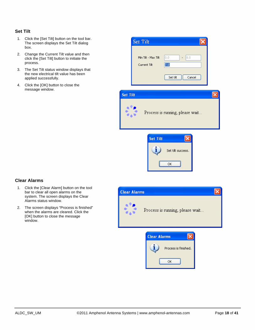
Set Tilt
1. Click the [Set Tilt] button on the tool bar. The screen displays the Set Tilt dialog box.
2. Change the Current Tilt value and then click the [Set Tilt] button to initiate the process.
3. The Set Tilt status window displays that the new electrical tilt value has been applied successfully.
4. Click the [OK] button to close the message window.
Clear Alarms
1. Click the [Clear Alarm] button on the tool bar to clear all open alarms on the system. The screen displays the Clear Alarms status window.
2. The screen displays “Process is finished” when the alarms are cleared. Click the [OK] button to close the message window.

Heading 1
ALDC_SW_UM ©2011 Amphenol Antenna Systems | www.amphenol-antennas.com Page 19 of 41
Self Test This function will:
• perform a self test operation on the selected device
• report the outcome of that test
Using the Self Test Function
1. Click the [Self Test] button on the tool bar. This will initiate the self test process.
2. The screen displays a message when the self test is complete. Click the [OK] button to close the message window.
Reset Software
1. Click the [Reset] button on the tool bar. This will initiate the process. The screen displays a Reset Software progress window.
2. The screen displays a message when the software settings have been reset. Click the [OK] button to close the message window.

Heading 1
ALDC_SW_UM ©2011 Amphenol Antenna Systems | www.amphenol-antennas.com Page 20 of 41
RET Detail Settings You can edit device information using the ALDC software. To display the detailed data for the selected device, click the [EDIT] button on the tool bar menu OR double-click on the highlighted row for the device. The screen displays the RET Detail Setting.
Antenna Installation Data
Column Name Description/Constraint
Sector ID Sector ID
Site ID Base station site ID
Installer’s ID Installer’s ID
Installation Date mmddyy format
Bearing Antenna bearing in the range of 0-359 degrees
Mechanical Tilt Installed mechanical tilt in degrees
Antenna Serial No. Antenna serial number (may already be factory programmed)
Changing Installation Information 1. Type the new data in the appropriate field(s).
2. Check the box(s) beside the field(s) that you would like to update.
NOTE Only the field with a check in the checkbox will be uploaded to the RET. This is intended to prevent accidental changes.
3. Click the [Save Selected] button to upload the revised information to the RET.
Heading 1
ALDC_SW_UM ©2011 Amphenol Antenna Systems | www.amphenol-antennas.com Page 21 of 41
Antenna Model Data
Column Name Description/Constraint
Antenna Model If you cannot find a proper antenna model for the RET, refer to “Add an Antenna Model” (pg #) for how to add your antenna model
WARNING: Changing the antenna model will upload a new configuration file to the RET device. DO NOT change the factor programmed antenna model name unless you are certain you know how to do so correctly. If uncertain, contact Amphenol Antenna Solutions technical support before changing this field.
Frequency Band Frequency band(s) used by the antenna
Beam Width Beamwidth for each band in frequency order.
Split by and/or displayed in order according to Frequency Band
Antenna Gain Gain for each band in frequency order
Split by and/or displayed in order according to Frequency Band
Changing the Antenna Model It is only appropriate to upload a new antenna model to the RET device in the following circumstances:
• When transferring a RET unit from one antenna model to a different antenna model
NOTE For external RET units, make sure that the RET electrical tilt and the antenna electrical tilt (as indicated by the dip stick) are set to the same setting before mechanically attaching the RET to the antenna.
• When upgrading the configuration file in the RET to a new release
NOTE It is rare that a new configuration file is required for an Amphenol Antenna Solutions RET device. Only upload a new configuration file when instructed to do so by technical support.
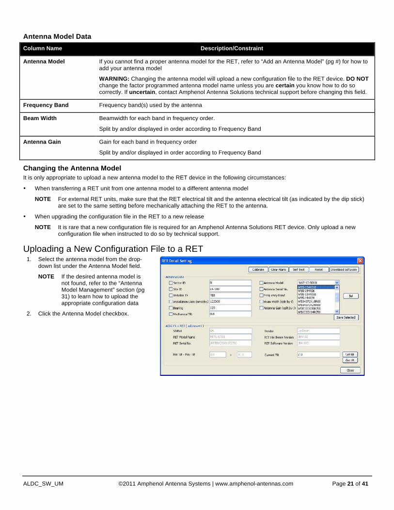
Uploading a New Configuration File to a RET
1. Select the antenna model from the drop-down list under the Antenna Model field.
NOTE If the desired antenna model is not found, refer to the “Antenna Model Management” section (pg 31) to learn how to upload the appropriate configuration data
2. Click the Antenna Model checkbox.

Heading 1
ALDC_SW_UM ©2011 Amphenol Antenna Systems | www.amphenol-antennas.com Page 22 of 41
NOTE Beamwidth and Gain are “information only” data fields and do not have any impact on the actual performance of the antenna.
Changing the Frequency Band 1. On The RET Detail Setting window, click
on the [Sel] button. The screen displays available frequencies.
2. Uncheck the checkbox of any frequency bands that do not apply to the current installation.
3. Click the [Apply] button. The selected frequency band(s) will be refreshed back into [Frequency Band]. For each selected frequency band, if there are built-in values for beam width and gain in the system, these built-in values will be shown in the [Beam Width] and [Antenna Gain] fields; otherwise the field displays 0.0.
NOTE This display will look different for AISG v2.0 devices due to enhancements to the AISG specification related to available frequency band codes.
3. Click the Save Selected button. The screen displays a Save Device Data confirmation dialog box.
4. Click the [OK] button. The application initiates the process to upload a new configuration file to the RET device.
5. The screen displays a status window; the
new model data has been saved.
6. Click the [OK] button to close this window.
NOTE Beamwidth and Gain do not automatically update when a new configuration file is uploaded to an Amphenol Antenna Solutions RET device.
7. Refer to the antenna datasheet and manually update these fields if they are no longer correct.

Heading 1
ALDC_SW_UM ©2011 Amphenol Antenna Systems | www.amphenol-antennas.com Page 23 of 41
RET Model Data
Column Name Description/Constraint
Status “OK” or device alarm messages
Vendor Vendor Name
RET Model Name RET model name
RET Serial No. RET serial number
RET Hardware Version RET hardware version
RET Software Version RET software version
Min Tilt – Max Tilt Allowed electrical tilt range of the selected antenna model
Current Tilt Tilt setting should be in the range of Min Tilt – Max Tilt
Set Tilt This function provides a second location within the software to change the electrical tilt of an antenna.
1. Click the [Set Tilt] button on the RET Detail Setting tool bar. This will initiate the process. The screen displays a Reset Software progress window.
2. The screen displays a message when the software settings have been reset. Click the [OK] button to close the message window.
Get Tilt This function interrogates the RET and then returns the current electrical tilt setting of an antenna.
Using the Get Tilt Function
1. Click the [Get Tilt] button on the tool bar.
2. The screen displays a message when the software settings have been reset. Click the [OK] button to close the message window.
Heading 1
ALDC_SW_UM ©2011 Amphenol Antenna Systems | www.amphenol-antennas.com Page 24 of 41
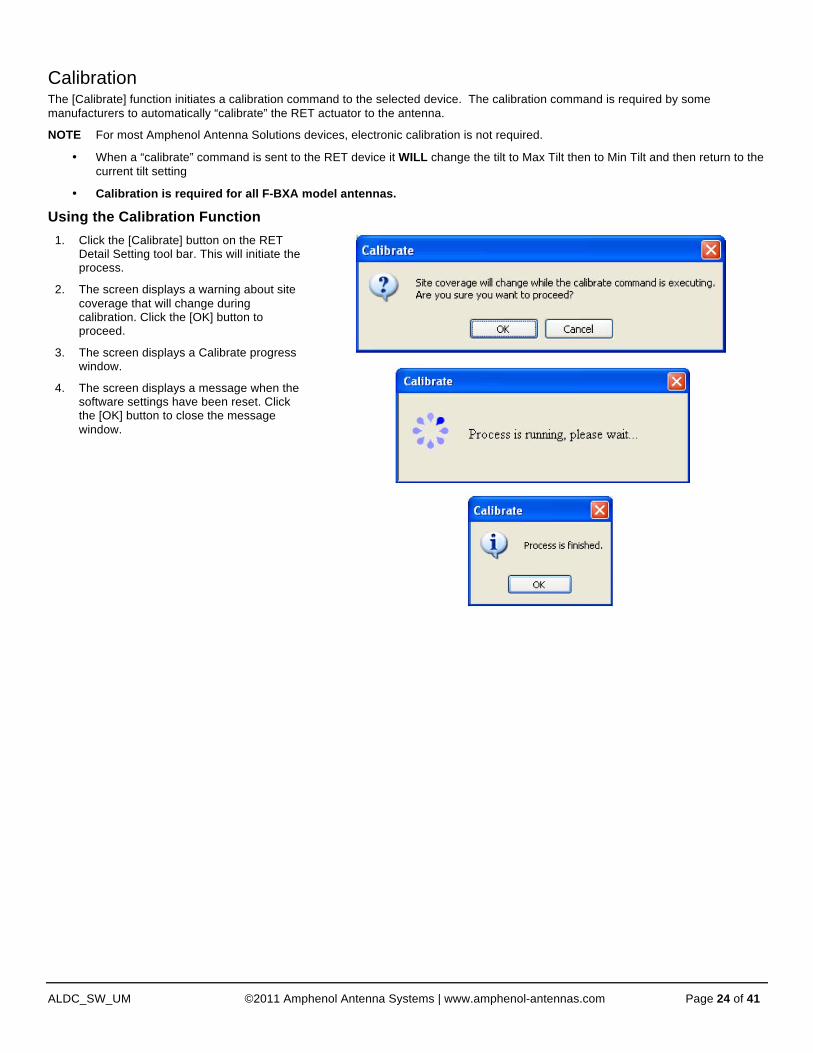
Calibration The [Calibrate] function initiates a calibration command to the selected device. The calibration command is required by some manufacturers to automatically “calibrate” the RET actuator to the antenna.
NOTE For most Amphenol Antenna Solutions devices, electronic calibration is not required.
• When a “calibrate” command is sent to the RET device it WILL change the tilt to Max Tilt then to Min Tilt and then return to the current tilt setting
• Calibration is required for all F-BXA model antennas.
Using the Calibration Function
1. Click the [Calibrate] button on the RET Detail Setting tool bar. This will initiate the process.
2. The screen displays a warning about site coverage that will change during calibration. Click the [OK] button to proceed.
3. The screen displays a Calibrate progress window.
4. The screen displays a message when the software settings have been reset. Click the [OK] button to close the message window.

Heading 1
ALDC_SW_UM ©2011 Amphenol Antenna Systems | www.amphenol-antennas.com Page 25 of 41
Download Software—RET and TMA This function provides the ability to upload new firmware to selected AISG device. This feature can also be used to upload a small .hex file to selected Amphenol Antenna Solutions RET devices to change the operating mode from AISG v1.1 to AISG v2.0 and vice versa.
Downloading Software
1. Click the [Download Software] button on the RET Detail Setting tool bar. The screen displays a window where you can select the file to upload to the device.
NOTE The software program provided by the device vendor MUST have either .bin or .hex extension.
2. Select a software file and then click the [Open] button.
3. The screen displays a confirmation window. Click the [OK] button. The system downloads the software file.
NOTE The software download might take up to 20 minutes, depending on file size.
4. The screen displays a message when the software download is finished. Click the [OK] button to close the message window.
NOTE When switching the AISG operating mode of an Amphenol Antenna Solutions RET, it may be necessary to re-scan the bus in order for the software to establish proper communication with the device and to display the updated AISG version.

Heading 1
ALDC_SW_UM ©2011 Amphenol Antenna Systems | www.amphenol-antennas.com Page 26 of 41
TMA Detail Settings You can edit detail information for a TMA device using the ALDC software. To display the detailed data for the selected device, click the [EDIT] button on the tool bar menu OR double-click on the highlighted row for the device. The screen displays the TMA Detail Setting.
Antenna Installation Data (See “Antenna Installation Data”) The antenna installation data fields for the TMA are identical to the fields previously described for the RET device.
Antenna Model Data (See “Antenna Model Data”) The only difference between the RET antenna model data and TMA antenna model data is that the [Antenna Model] field does not upload an antenna configuration file to the device.
This field is a text-only field that is updated during installation to identify which serial number antenna the TMA is amplifying.
Heading 1
ALDC_SW_UM ©2011 Amphenol Antenna Systems | www.amphenol-antennas.com Page 27 of 41
TMA Model Data Column Name Description/Constraint
Status “OK” or device alarm messages
Vendor Vendor Name
TMA Model Name TMA model name
TMA Serial No. TMA serial number
TMA Hardware Version TMA hardware version
TMA Software Version TMA software version
Min – Max Rx Freq. Band Allowed receive frequency band range
Min – Max Tx Freq. Band Allowed transmit frequency band rang
Min Gain – Max Gain Allowed gain range of the TMA model
Gain Resolution Gain increment from minimum gain to maximum gain.
For fixed gain or non-linear gain TMA, this value is always zero. Type TMA type can be “Bypass” and/or “VSWR”
Mode TMA mode can be “Bypass” or “Normal”
Current Gain The value should be in the range of Min Gain – Max Gain
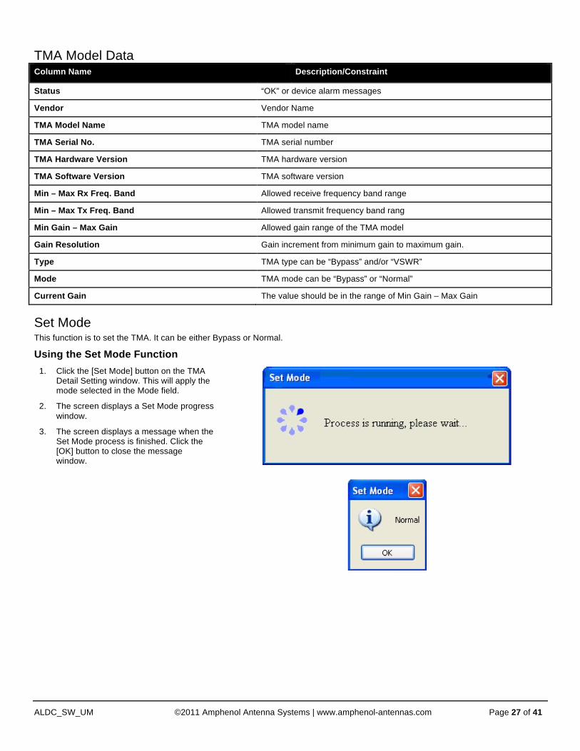
Set Mode This function is to set the TMA. It can be either Bypass or Normal.
Using the Set Mode Function
1. Click the [Set Mode] button on the TMA Detail Setting window. This will apply the mode selected in the Mode field.
2. The screen displays a Set Mode progress window.
3. The screen displays a message when the Set Mode process is finished. Click the [OK] button to close the message window.

Heading 1
ALDC_SW_UM ©2011 Amphenol Antenna Systems | www.amphenol-antennas.com Page 28 of 41
Get Mode This function will interrogate the TMA device to determine the current TMA mode.
Using the Get Mode Function
1. Click the [Get Mode] button on the TMA Detail Setting window.
2. The screen displays the current TMA mode setting.
3. Click the [OK] button to close the message window.
Set Gain This function will set the TMA gain. TMA gain MUST fall between minimum and maximum gain values.
Using the Set Gain Function
1. Click the [Set Gain] button on the TMA Detail Setting window. The ALDC applies the gain value selected in the [Current Gain] field.
2. If this functionality is not supported by the device, the screen may display an “Unsupported Proc” or “Read Only” message to indicate the function is not supported, or displays a message that the gain value has been applied successfully.
Get Gain This function will interrogate the TMA device to determine the current TMA gain value.
Using the Get Gain Function
1. Click the [Get Gain] button on the TMA Detail Setting window.
2. The screen displays the current TMA gain value setting.
3. Click the [OK] button to close the message window.
Heading 1
ALDC_SW_UM ©2011 Amphenol Antenna Systems | www.amphenol-antennas.com Page 29 of 41
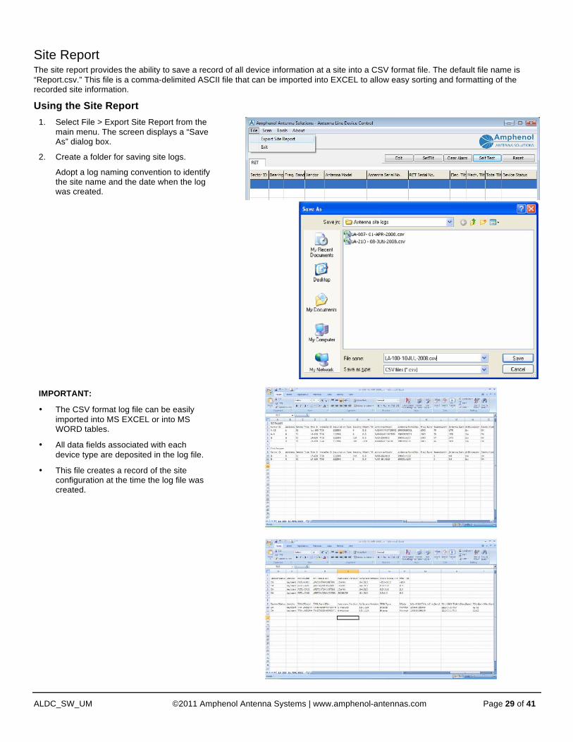
Site Report The site report provides the ability to save a record of all device information at a site into a CSV format file. The default file name is “Report.csv.” This file is a comma-delimited ASCII file that can be imported into EXCEL to allow easy sorting and formatting of the recorded site information.
Using the Site Report
1. Select File > Export Site Report from the main menu. The screen displays a “Save As” dialog box.
2. Create a folder for saving site logs.
Adopt a log naming convention to identify the site name and the date when the log was created.
IMPORTANT:
• The CSV format log file can be easily imported into MS EXCEL or into MS WORD tables.
• All data fields associated with each device type are deposited in the log file.
• This file creates a record of the site configuration at the time the log file was created.
Heading 1
ALDC_SW_UM ©2011 Amphenol Antenna Systems | www.amphenol-antennas.com Page 30 of 41
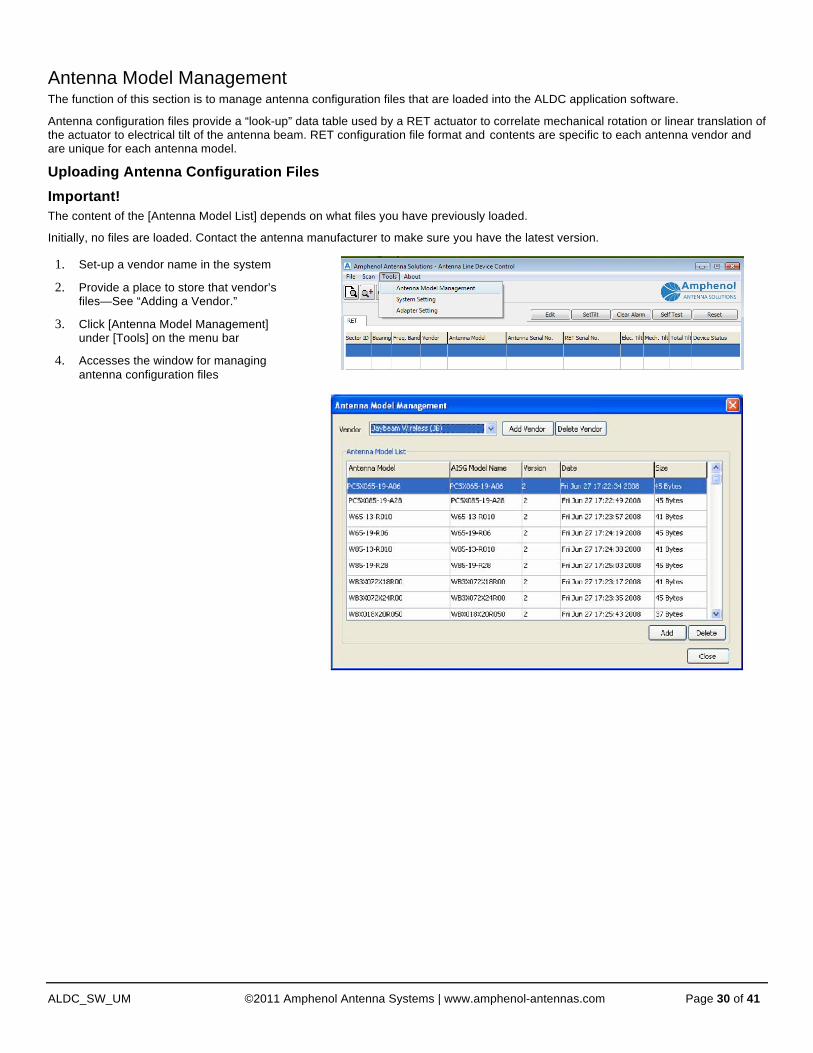
Antenna Model Management The function of this section is to manage antenna configuration files that are loaded into the ALDC application software.
Antenna configuration files provide a “look-up” data table used by a RET actuator to correlate mechanical rotation or linear translation of the actuator to electrical tilt of the antenna beam. RET configuration file format and contents are specific to each antenna vendor and are unique for each antenna model.
Uploading Antenna Configuration Files
Important! The content of the [Antenna Model List] depends on what files you have previously loaded.
Initially, no files are loaded. Contact the antenna manufacturer to make sure you have the latest version.
1. Set-up a vendor name in the system
2. Provide a place to store that vendor’s files—See “Adding a Vendor.”
3. Click [Antenna Model Management] under [Tools] on the menu bar
4. Accesses the window for managing antenna configuration files

Heading 1
ALDC_SW_UM ©2011 Amphenol Antenna Systems | www.amphenol-antennas.com Page 31 of 41
Add a Vendor The vendor must exist in the [Vendor] list before you can upload configuration files for that vendor.
Adding a Vendor
1. Click the [Add Vendor] button on the Antenna Model Management window. The screen displays the Add Vendor dialog box.
2. Enter the two-letter AISG Vendor code for the vendor you would like to add.
NOTE Refer to the next page or www.AISG.org.uk for vendor codes.
3. Click the [Add] button. This action initiates the Add Vendor process.
4. The screen displays a status message when the process is complete. Click on the [OK] button to close the message window.

Heading 1
ALDC_SW_UM ©2011 Amphenol Antenna Systems | www.amphenol-antennas.com Page 32 of 41
AISG Vendor Codes: Vendor Code Company Name Vendor Code Company Name AA Alcatel LA Powerwave Technologies Inc AC ADC, Inc LG Powerwave Technologies Inc AD Alan Dick and Co Ltd LO Lorch Microwave Inc AE ACE Technology Corporation LU Lucent Technologies AF Aerial Facilities Ltd MA Jaybeam Wirless Al Amphenol Antenna Solutions (formerly Amphenol
Antel, Inc.) MD Microdata Telecom Innovation AB
AM ARIALCOM SA MI Mitec Inc AN Andrew Corporation ML Microlab/FXR AR Argus Technologies (Austrilia) Pty Ltd MO Motorola AV Avitec AB MT Mobile Antenna Technologies (Shenzhen)
Co., Ltd AW Antone Wireless Corp MY Sistemas Radiantes, F. Moyano, S.A. AX Axis Network Technology Ltd NA NEC ANTEN Ltd BT Bravo Tech Inc. ND Nihon Dengyo Kosaku Co Ltd BW Böke & Walterfang Ltd NK Nokia CB Comba Telecom NN Nortel Networks CC CSS Antenna Inc. NT Netop Technology CE C3EM SA NX NXP CI Communication Components Inc PC PCTEL, Inc. CL ClearComm Technologies, LLC PO Polyphaser Corp. CM Combilent A/S PR Prism Microwave LLC CO Comba Telecom PW PowerWave Technologies Inc CS Jaybeam Wirless QU Quintel Ltd CT Celletra, Inc RA Racal Antennas Ltd CX Cellmax Technologies RC Radio Components Sweden AB DA DAPA Systemes SA RD Radio Design Ltd DB Andrew Corporation RE Powerwave Technologies Inc DK Denki Kogyo Co Ltd RF RFS Inc EB Elektrobit Ltd RK R&K Company Ltd EM EMS Technologies, Inc RM RFM Wireless ET ETSA RY RYMSA SA ER Ericsson SA SPAA05 EY Eyecom Technologies SD SDP Components Inc FG Wuhan Fingu Electoinc Co Ltd SE Selecom SA FI Filtronic Ltd SH University of Sheffield (UK) FO Andrew Corporation SM Siemens AG FR Fractus SA SI Sigma Wireless Technology Ltd FU Furukawa Communications & Broadcasting Co Ltd SP Spinner GmbH GN Gamma Nu Inc SQ Signal Quest, Inc GR Grintek Antennas SR Guangzhou Sunrise Telecom Eqpt Co Ltd. GT Gemintek Corporation SS Sunsight Instruments LLC HE Xiamen Helios Telecom Equipment Manufacture Inc ST Stella Doradus Waterford Ltd HG High Gain Antenna Co SU Sunwave Communications Co Ltd HI Hitachi Cable Co Ltd SW Sunwave Tec HH HCS-HES Cabling Systems TH Racal Antennas Ltd HS Huber + Suhner TN Telnet Redes Inelligentes HX Wuhan Hongzin Telecoms Technologies TR Triasx Pty. Ltd, IT Innerton, Inc. TT Jiangsu JST Technologies (Nanjing) Co Ltd JB Jaybeam Wireless TY Tongyu Communications Equipment Co HW Huawei Technology Ltd TX TenXc Wireless Inc. KA Kathrein KG UW Unity Wireless Corporation KL K & L Microwave Inc VX Voxaura Technologies Inc KM KMW Ltd XH Xi’an Haitian Antenna Technologies Co Ltd
NOTE The existence of an assigned Vendor Code does not indicate that the company to which it was assigned is still manufacturing or trading under the name shown nor that is a member of AISG.
Heading 1
ALDC_SW_UM ©2011 Amphenol Antenna Systems | www.amphenol-antennas.com Page 33 of 41
Delete a Vendor IMPORTANT NOTE: Before deleting a vendor, you HAVE to make sure no model exists under this vendor
If there is a model stored under the selected vendor
• A warning message will appear
• The vendor WILL NOT be deleted
Deleting a Vendor 1. Select the vendor that you would like to delete from the [Vendor] list
2. Click the [Delete Vendor] button next to the [Vendor] list
3. Click [OK] to close the confirmation window.
4. Delete the selected vendor from the system
5. Refresh the [Vendor] list
6. Click [OK] to close the window that will appear to show that the process was a success.
Add an Antenna Model This function will upload a configuration file from the selected vendor to the specific location in the PC.
NOTE The vendor MUST exist in the [Vendor] list before antenna models can be uploaded.
Adding an Antenna Model 1. Select a vendor from the [Vendor] list
2. Click the [Add] button below the Antenna Model list, which uploads a configuration file from that vendor
Column Name Description/Constraint
Vendor Name Vendor Name
Config File File name with its full path should be provided
Only a file less than 0.5 KB with extensions of .bin, .RETbin or .acf is allowed.
Antenna Model Name Antenna model name
NOTE The configuration file name will be used as the default model name that is allowed to be changed.
AISG Model Name The model name will be stored in RET device.
NOTE The maximum length of AISG model name is 15 characters.
Version The antenna model configuration file version (optional)
3. Browse your computer to find the configuration file provided by your antenna vendor.
NOTE If it is an Amphenol Antenna Solutions .RETbin file that contains the Config. File version code as part of the file name, see step 5. If this is not the case, skip to step 6
4. Edit the Antenna Model Name and Version fields before selecting [Add] to document the version code to the appropriate location
5. ONLY if the Amphenol Antenna Solutions .RETbin file contains the Config. File version code as a part of the file name.
6. Click the [OK] button to close the message window that signifies success.
Delete an Antenna Model This function will delete a selected antenna model from the system.
1. Click the [Delete] button, which will cause a confirmation window to appear
2. Click the [OK] button to delete the selected antenna model
Heading 1
ALDC_SW_UM ©2011 Amphenol Antenna Systems | www.amphenol-antennas.com Page 34 of 41
Appendix A: Changing AISG Communications Mode Amphenol Antenna Solutions RET units are designed to operate in either AISG v1.1 or AISG v2.0/3GPP communications mode.
Switching Between Communication Modes A very small file must be sent to the RET using the “Download Software” feature of the primary controller.
Changing Communication Modes (Using the ALDC v2.0 Primary Control Software)
1. Locate Files
a. Locate the folder “AISG Mode” containing the files:
“ChangeToAisgV1.hex”
OR
“ChangeToAisgV2.hex”
NOTE These files were provided with your software installation CD.
b. Store these files in the same directory where the ALDC software is store
2. Verify the Current AISG Mode
A. Find the current AISG operating mode for a RET device by double-clicking on the device in the main menu or selecting the [Edit] tab.
NOTE The AISG mode is displayed in the location indicated in the picture.
3. Change the Communications Mode
a. Click the [Download Software] button, which launches the window where you can select the file to upload the device.
b. Select the file whose name matches the operation you would like to perform.
c. Click the [Open] button after selecting the file, which will cause a confirmation window to appear
d. Click the [OK] button to initiate the download process
e. Click the [OK] button to close the message window that signals the process was a success.
f. Verify that the communications mode was changed correctly
g. Double-click on the device in the main menu or select the [Edit] button
h. Verify that the new AISG mode is displayed

Heading 1
ALDC_SW_UM ©2011 Amphenol Antenna Systems | www.amphenol-antennas.com Page 35 of 41
Appendix B: Remote Azimuth Steering (RAS)
Overview Standard AISG-ES-RAS v2.1.0 was released by the Antenna Interface Standards Group (AISG) is December 2007 as an optional extension to AISGv2.0 to define procedures for controlling Remote Azimuth Steering (RAS) devices.
Unfortunately, this specification has the following practical limitations:
• RAS device types are not
o Yet supported by many OEM primary controllers
o Recognized by legacy AISGv1.1 controllers
In order to overcome these limitations Jaybeam Wireless has developed two-way adjustable (RET/RAS) antennas using the following internal device configuration:
In this configuration two separate actuators are installed inside the antenna.
One actuator is used to control elevation beam tilt, while the other actuator is used to control azimuth beam steering. BOTH actuators are programmed as a “RET” device type according to the AISG standard.
This enables the antenna to be controlled using legacy AISGv1.1 controllers as well as the newer AISGv2.0 systems.
The only drawback to this approach is that care MUST be given during site set-up to clearly identify the function of each “RET” device found.
Heading 1
ALDC_SW_UM ©2011 Amphenol Antenna Systems | www.amphenol-antennas.com Page 36 of 41
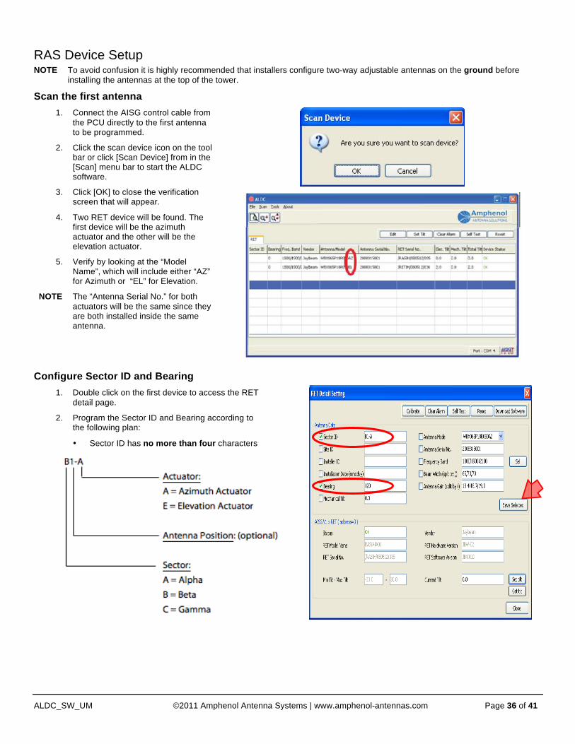
RAS Device Setup NOTE To avoid confusion it is highly recommended that installers configure two-way adjustable antennas on the ground before
installing the antennas at the top of the tower.
Scan the first antenna
1. Connect the AISG control cable from the PCU directly to the first antenna to be programmed.
2. Click the scan device icon on the tool bar or click [Scan Device] from in the [Scan] menu bar to start the ALDC software.
3. Click [OK] to close the verification screen that will appear.
4. Two RET device will be found. The first device will be the azimuth actuator and the other will be the elevation actuator.
5. Verify by looking at the “Model Name”, which will include either “AZ” for Azimuth or “EL” for Elevation.
NOTE The “Antenna Serial No.” for both actuators will be the same since they are both installed inside the same antenna.
Configure Sector ID and Bearing
1. Double click on the first device to access the RET detail page.
2. Program the Sector ID and Bearing according to the following plan:
• Sector ID has no more than four characters

Heading 1
ALDC_SW_UM ©2011 Amphenol Antenna Systems | www.amphenol-antennas.com Page 37 of 41
Configure Sector ID and Bearing, cont. • Bearing (0-359)—Enter the PLANNED
mechanical pointing direction of the antenna after installation expressed in degrees East of True North (ETN)
NOTE This is based on the site plan
3. Repeat steps 1 and 2 for the Elevation actuator.
NOTE Mark the Sector ID ON the antenna so that the installation crew will know where to install the antenna!
4. Repeat steps 1 and 2 for ALL antennas at this site.
5. Using the AISG control cables for this sites, connect ALL antennas together and scan, verifying:
• That all AISG cables are function correctly
• That the actuators have been programmed correctly
6. Install the antennas.
The Antenna Azimuth Setting The Electrical Tilt of each azimuth actuator is equivalent to the Azimuth Offset as defined by the AISG-ES-RAS v2.1.0 extension:
• “Azimuth Offset is equal to the angle, expressed in degrees, between the azimuth bearing of an antenna and the maximum of its main beam in the azimuth plane
o A positive azimuth offset means that the antenna beam is directed to a compass heading numerically greater than the azimuth bearing.
o An antenna has separate values for azimuth bearing and azimuth offset.
o The azimuth bearing is fixed by the geometry of the installation.
o The azimuth offset is remotely controllable and variable.”
Changing the Antenna Azimuth Setting
1. Select the azimuth actuator of the antenna you would like to adjust.
2. Select [Set Tilt] from the menu bar.
3. Enter the number of degrees you would like to rotate the antenna beam, based on the view from above the antenna.
• Positive is a clockwise rotation
• Negative is a counter clockwise rotation
4. Click the [Set tilt] button.

Heading 1
ALDC_SW_UM ©2011 Amphenol Antenna Systems | www.amphenol-antennas.com Page 38 of 41
Changing the Antenna Azimuth Setting
5. A message will appear notifying you that the process was successful. Click the [OK] button to close the message window.
6. The Azimuth offset will now appear on the display in the “Elec. Tilt” column indicating the change in the beam direction.
True beam direction can be determined by adding the “Bearing” to the “Elec. Tilt.”
Example The azimuth pointing direction of the antenna beam equals:
120 degrees + (-10 degrees) = 110 degrees

Header
Amphenol Antenna Solutions 1300 Capital Drive
Rockford, Illinois 61109 USA
+1 815.399.0001
www.amphenol-antennas.com