Chapter 6: Antenna Arrays Session 1
22
EELE 5333 Antenna & Radio Propagation Part II: Antenna families Winter 2020 Re-Prepared by Dr. Mohammed Taha El Astal Chapter 6: Antenna Arrays Session 1
-
Upload
khangminh22 -
Category
Documents
-
view
6 -
download
0
Transcript of Chapter 6: Antenna Arrays Session 1

EELE 5333
Antenna & Radio
Propagation
Part II: Antenna families
Winter 2020
Re-Prepared byDr. Mohammed Taha El Astal
Chapter 6: Antenna Arrays
Session 1

Acknowledgment
This PPT is prepared based mainly on Dr.Talal Skaik’s PPT and BalanisAntenna Book

• Usually the radiation patterns of single-
element antennas are relatively wide, i.e.,
they have relatively low directivity (gain).
• Enlarging the dimensions of single
elements often leads to more directive
characteristics.
• Another way to increase directivity is by
assembly of radiating elements in a proper
electrical and geometrical configuration to
form antenna array.3
Introduction

• Usually, the array elements are identical. This is not necessary but it is practical
and simpler for design and fabrication.
• The individual elements may be of any type (wire dipoles, loops, apertures, etc.)
4
Antenna Arrays
Array of four helical antennas used as a satellite tracking antenna, Pleumeur-Bodou, France
Large planar array antenna of a VHF Russianmobile air defense radar, the Nebo-M. Itconsists of 175 folded dipole antennas.

• To provide very directive pattern, it isnecessary that the partial fields (generatedby the individual elements) interfereconstructively in the desired directionand interfere destructively in theremaining space.
5
Antenna Arrays
• Arrays can provide the capability of asteerable beam (radiation directionchange).

In an array of identical elements, there are at least five controls that can be used to shape the overall pattern of the antenna. These are:
6
Antenna Arrays
The geometrical configuration of the overall array (linear,
circular, rectangular, spherical, etc.)
The relative displacement between the elements
The excitation amplitude of the individual elements
The excitation phase of the individual elements
The relative pattern of the individual elements

7
Depending in the physical location of the discrete elements:
Antenna Arrays Types, based on geometrical configuration
8
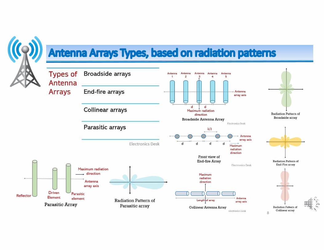
Antenna Arrays Types, based on radiation patterns

9
Antenna Arrays

Let us assume that the antenna under investigation is an array of two infinitesimal horizontal dipoles positioned along the z-axis.
10
Antenna Arrays-Two Element Array

11
Antenna Arrays-Two Element ArrayThe total field radiated by the two elements, assuming no coupling between the elements, is equal to the sum of the two and in the y-z plane it is given by:
where β is the difference in phase excitation between the elements. The magnitude excitation of the radiators is identical.
)2/(02
)2/(01
j
j
eII
eII

12
Antenna Arrays-Two Element Array
Assuming far field observations

13
Assuming far field observations
Antenna Arrays-Two Element Array

• The total field of the array is equal to the field of a single element positioned atthe origin multiplied by a factor which is widely referred to as the Array Factor.
• Thus for the two-element array of constant amplitude, the array factor is given by:
which in normalized form can be written as
14
Antenna Arrays-Two Element Array

• The array factor is a function of the geometry of the array and the excitation phase.
• By varying the separation d and/or the phase β between the elements, the characteristics of the array factor and of the total field of the array can be controlled.
• It has been illustrated that the far-zone field of a uniform two-element array of identical elements is equal to the product of the field of a single element, at a selected reference point (usually the origin), and the array factor of that array. That is,
• This is referred to as pattern multiplication for arrays of identical elements15
Antenna Arrays-Two Element Array

ExampleFor the previous array, find the nulls of the total field when d=λ/4 and:β=0 , β=+π/2 , β=+π/2
16
For β=0 : The only null occurs at θ = 90◦ and is due to the pattern of the individual elements. There is not enough separation between the elements to introduce a phase difference of 180◦ between the elements.
Antenna Arrays-Two Element Array (Example)

17
For β=0
The array factor is nearly isotropic, the element pattern and the total pattern are almost identical in shape.
Antenna Arrays-Two Element Array (Example)

18
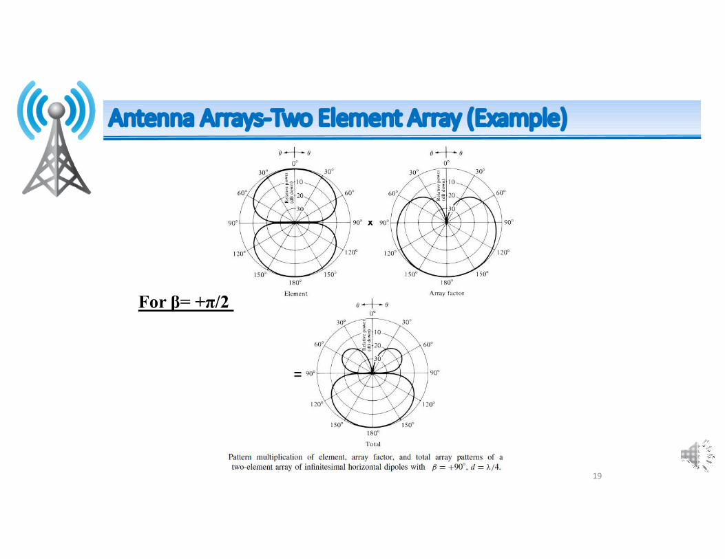
For β= +π/2 :
The nulls of the array occur at θ = 90◦ and 0◦. The null at 0◦ is introduced by the arrangement of the elements (array factor).
Antenna Arrays-Two Element Array (Example)
19
For β= +π/2
Antenna Arrays-Two Element Array (Example)

20
For β= -π/2 :
The nulls occur at 90◦ and 180◦.
Antenna Arrays-Two Element Array (Example)

21
For β= -π/2
Antenna Arrays-Two Element Array (Example)