Performance of Wireless CDMA with Mary Orthogonal Modulation and Cell Site Antenna Arrays
14
1770 IEEE JOURNAL ON SELECTED AREAS IN COMMUNICATIONS, VOL. 14, NO. 9, DECEMBER 1996 Ayman F. Naguib, Member, IEEE, and Arogyaswami Paulraj, Fellow, IEEE Abstract- In this paper, an antenna array-based base sta- tion receiver structure for wireless direct-sequence code-division multiple-access (DSKDMA) with AI-ary orthogonal modulation is proposed. The base station uses an antenna array Beamformer- RAKE structure with noncoherent equal gain combining. The receiver consists of a “front end” beamsteering processor feeding a conventional noncoherent RAKE combiner. The performance of the proposed receiver with closed loop power control in mul- tipath fading channels is evaluated. Expressions for the system uncoded bit-error probability (BEP) as a function of number of users, number of antennas, and angle spread are derived for different power control scenarios. The system capacity in terms of number of users that can be supported for a given nncoded BEP is also evaluated. Analysis results show a performance improvement in terms of system capacity due to the use of antenna arrays and the associated signal processing at the base station. In particular, analysis results show an increase in system capacity that is proportional to the number of antennas. They also show an additional performance improvement due to space diversity gain provided by the array for nonzero angle spreads. I. INTRODUCTION IRECT-SEQUENCE code-division multiple-access (DS/CDMA) is an emerging technology for civilian wire- less communications. CDMA offers improved performance in terms of capacity or coverage area over frequency-division multiple-access (FDMA) or time-division multiple-access (TDMA) based cellular networks [11-[41. One approach to further increase the system performance is the use of spatial processing with base station antenna arrays 151-[8]. By using spatial processing at cell sites, we can use optimum directional receive and transmit beams for each user to improve coverage or increase capacity. The increase in system performance by using antenna arrays in CDMA comes from reduction of cochannel interference from own cell and neighboring cells. In general, this reduction in cochannel interference can be used to improve other system performance measures such as coverage area, transmitted mobile power, and system capacity. In [9], we proposed a base station antenna array Beamformer-RAKE receiver that exploits the spatial structure in the multipath received signal in addition to the time diversity to provide a more efficient combining of paths. This receiver incorporates a “front-end’’ beamsteering processor feeding a conventional coherent RAKE combiner, which assumes knowledge of the amplitudes and phases of path gains. This requires the transmission of a pilot signal to obtain good amplitude and phase estimates. However, transmitting a pilot in each user‘s reverse link signal, whose power is greater than the data-modulated portion of the signal, reduces efficiency to less than 50%. Instead, either differential phase shift keying (DPSK) which does not require phase coherence or M-ary orthogonal modulation with noncoherent reception should be used. For M > 8, where M is the number of orthogonal signals, orthogonal modulation is better than DPSK [lo], [ll]. Analysis results for CDMA communications systems employing DPSK are reported in [12]-[15]. The analysis in [15] also assumes a base station antenna array receiver structure. Analysis for DS/CDMA with M-ary orthogonal modulation but without antenna arrays has appeared in [16]-[20]. The use of very low rate orthogonal codes in spread spectrum multiple access is considered in [16]. The analysis in [17] is done for the additive white Gaussian noise (AWGN) channel. However, the analysis in [ 181 models the multiple-access interference (MAI) as Gaussian noise and considers a multipath Rayleigh-fading channel [19]. The analysis in [20] is done for a general multipath energy distribution. In this paper, we propose an antenna array-based base station receiver structure for DS/CDMA with M-ary orthogo- nal modulation and noncoherent RAKE combining and study its performance. The receiver consists of an antenna array followed by a bank of Walsh correlators. The base-band received signal vector and the post-correlation signal vector are used to estimate the channel vector for each path. The output of the correlators is then fed to an optimum beamformer followed by a noncoherent RAKE combiner. The output of the RAKE combiner is then used to estimate the transmitted data. Assuming that the channel parameters are almost constant over several symbol periods, the output of the RAKE is also fed back to the channel vector estimation algorithm to determine the winning post-correlation signal vector which corresponds to the actual transmitted Walsh symbol. we may note that, in this paper drew Some of the analysis results in [19] and [20], they are different in the sense that they are done for a base station receiver with an antenna array and include the effect of closed loop power control. Manuscript received May 1, 1995; revised November 22, 1995. This paper was presented in part at the IEEE ICC’95 Conference, Seattle, WA, June 1995. A. F. Naguib was with the Information Systems Laboratory, Department of Electrical Engineering, Stanford University, Stanford, CA 94305 USA. He is now with the Information Sciences Research Center, AT&T Laboratories, Murry Hill, NJ 07974 USA (email: [email protected]). A. Paulraj is with the Information Systems Laboratory, Department of Electrical Engineering, Stanford University, Stanford, CA 94305 USA. Publisher Item Identifier S 0733-87 16(96)05239-0. the 0733-8716/96$05.00 0 1996 IEEE
-
Upload
independent -
Category
Documents
-
view
0 -
download
0
Transcript of Performance of Wireless CDMA with Mary Orthogonal Modulation and Cell Site Antenna Arrays

1770 IEEE JOURNAL ON SELECTED AREAS IN COMMUNICATIONS, VOL. 14, NO. 9, DECEMBER 1996
Ayman F. Naguib, Member, IEEE, and Arogyaswami Paulraj, Fellow, IEEE
Abstract- In this paper, an antenna array-based base sta- tion receiver structure for wireless direct-sequence code-division multiple-access (DSKDMA) with AI-ary orthogonal modulation is proposed. The base station uses an antenna array Beamformer- RAKE structure with noncoherent equal gain combining. The receiver consists of a “front end” beamsteering processor feeding a conventional noncoherent RAKE combiner. The performance of the proposed receiver with closed loop power control in mul- tipath fading channels is evaluated. Expressions for the system uncoded bit-error probability (BEP) as a function of number of users, number of antennas, and angle spread are derived for different power control scenarios. The system capacity in terms of number of users that can be supported for a given nncoded BEP is also evaluated. Analysis results show a performance improvement in terms of system capacity due to the use of antenna arrays and the associated signal processing at the base station. In particular, analysis results show an increase in system capacity that is proportional to the number of antennas. They also show an additional performance improvement due to space diversity gain provided by the array for nonzero angle spreads.
I. INTRODUCTION
IRECT-SEQUENCE code-division multiple-access (DS/CDMA) is an emerging technology for civilian wire-
less communications. CDMA offers improved performance in terms of capacity or coverage area over frequency-division multiple-access (FDMA) or time-division multiple-access (TDMA) based cellular networks [11-[41.
One approach to further increase the system performance is the use of spatial processing with base station antenna arrays 151-[8]. By using spatial processing at cell sites, we can use optimum directional receive and transmit beams for each user to improve coverage or increase capacity. The increase in system performance by using antenna arrays in CDMA comes from reduction of cochannel interference from own cell and neighboring cells. In general, this reduction in cochannel interference can be used to improve other system performance measures such as coverage area, transmitted mobile power, and system capacity.
In [9], we proposed a base station antenna array Beamformer-RAKE receiver that exploits the spatial structure
in the multipath received signal in addition to the time diversity to provide a more efficient combining of paths. This receiver incorporates a “front-end’’ beamsteering processor feeding a conventional coherent RAKE combiner, which assumes knowledge of the amplitudes and phases of path gains. This requires the transmission of a pilot signal to obtain good amplitude and phase estimates. However, transmitting a pilot in each user‘s reverse link signal, whose power is greater than the data-modulated portion of the signal, reduces efficiency to less than 50%. Instead, either differential phase shift keying (DPSK) which does not require phase coherence or M-ary orthogonal modulation with noncoherent reception should be used. For M > 8, where M is the number of orthogonal signals, orthogonal modulation is better than DPSK [lo], [ l l ] . Analysis results for CDMA communications systems employing DPSK are reported in [12]-[15]. The analysis in [15] also assumes a base station antenna array receiver structure. Analysis for DS/CDMA with M-ary orthogonal modulation but without antenna arrays has appeared in [16]-[20]. The use of very low rate orthogonal codes in spread spectrum multiple access is considered in [16]. The analysis in [17] is done for the additive white Gaussian noise (AWGN) channel. However, the analysis in [ 181 models the multiple-access interference (MAI) as Gaussian noise and considers a multipath Rayleigh-fading channel [19]. The analysis in [20] is done for a general multipath energy distribution.
In this paper, we propose an antenna array-based base station receiver structure for DS/CDMA with M-ary orthogo- nal modulation and noncoherent RAKE combining and study its performance. The receiver consists of an antenna array followed by a bank of Walsh correlators. The base-band received signal vector and the post-correlation signal vector are used to estimate the channel vector for each path. The output of the correlators is then fed to an optimum beamformer followed by a noncoherent RAKE combiner. The output of the RAKE combiner is then used to estimate the transmitted data. Assuming that the channel parameters are almost constant over several symbol periods, the output of the RAKE is also fed back to the channel vector estimation algorithm to determine the winning post-correlation signal vector which corresponds to the actual transmitted Walsh symbol. we may note that,
in this paper drew Some of the analysis results in [19] and [20], they are different in the sense that they are done for a base station receiver with an antenna array and include the effect of closed loop power control.
Manuscript received May 1, 1995; revised November 22, 1995. This paper was presented in part at the IEEE ICC’95 Conference, Seattle, WA, June 1995.
A. F. Naguib was with the Information Systems Laboratory, Department of Electrical Engineering, Stanford University, Stanford, CA 94305 USA. He is now with the Information Sciences Research Center, AT&T Laboratories, Murry Hill, NJ 07974 USA (email: [email protected]).
A. Paulraj is with the Information Systems Laboratory, Department of Electrical Engineering, Stanford University, Stanford, CA 94305 USA.
Publisher Item Identifier S 0733-87 16(96)05239-0.
the
0733-8716/96$05.00 0 1996 IEEE

NAGUlB AND PAULRAJ: PERFORMANCE OF WIRELESS CDMA WITH M-ARY ORTHOGONAL MODULATION 1771
Speech
Convolutional Encoder
Repetition
A Interleaver
I-Channel Short Code
cos(o,t)
+xGiGq* Filter
M-ary Orthogonal Walsh Modulator
1 M-ary Orthogonal I Interleaver 1- SE Walsh Modulator __c
WO) J bits
sin(o,t) Generator c,(r) User
Mask
t e.l+r?Y Delay Filter I + Power Control
sin(o,t)
Long Code Q-Channel Short Code
Fig. 1. Mobile transmitter block diagram.
This paper is organized as follows. In Section 11, we present the channel and received signal model. In Section 111, we describe the antenna array receiver structure. System analysis and derivation of the signal and decision variables statistics are given in Section IV. The probability of error analysis is given in Section V. Numerical and simulation results are presented
and the I or Q channel PN code as
c!”(t) = c,(t)a(’)(t) and c,‘”(t) 1 cZ(t)a(&j( t ) .
To simplify our analysis, the PN codes cz(C ( t ) and ,,‘&I ( t ) are represented by [201, [221
in Section VI. Finally, Section VI1 contains our conclusions and remarks.
11. SIGNAL AND CHANNEL MODEL
The mobile transmitter block diagram [21] is shown in Fig. 1. The binary data at the output of the interleaver are grouped into groups of J = log,M bits. Each group is mapped into one of M orthogonal Walsh sequences W(t) . The resulting signal is then spread using the user’s long PN code e,@). The signal is further multiplied in both 1 and Q channels by the short PN codes a(’)(t) and ~ ( ~ ) ( t ) , respectively. The PN modulated Q channel signal is delayed by half a chip period Tc/2. The two spread signals are up- converted to radio frequency for transmission. The power of the transmitted signal is adjusted according to both the open and closed loop power control mechanisms (see, e.g., [21]). Then we can write the signal transmitted by the ith mobile as
&(t) = QZ ~ ( W ( h , ( t ) c , ( t ) a ( l ) ( t ) cos(w,t)
+ W y t - T,)c,(t - T,)a(Q) x (t - T,) sin(w,t)) 0 5 t I: T, (1)
where P, is the transmitted power per symbol per dimension, T, is the symbol period, w, is the carrier angular frequency, T, = Tc/2 is the time offset between the I and Q channels, and finally $ J ~ is a Bernoulli random variable that models the voice activity of the ith user (we assume that a user will be on with probability v and will be off with probability 1 - v). W ( h ) ( t ) is the hth orthogonal Walsh function, h = 1, . . . , M . Let the processing gain be G = TWITc. For simplicity of notation, we shall denote the product of the user’s PN code
r=--Oo
00
(3 ) r=--00
where c!fr’ and e$!) are assumed to be independent and identically distributed (i.i.d.) random variables taking values 6 1 with equal probability, and p ( t ) is the chip pulse shape, which can be any time-limited waveform. Here we assume that p ( t ) is rectangular although our results can be easily extended for any time-limited waveform.
To simplify our analysis, we assume that we have a constant deterministic power-delay profile and that the log-normal slow fading is the same for all multipath components. Therefore, we can write the complex lowpass equivalent representation of the vector multipath fading channel from the zth user to the base station antenna array as [23]
L,
h t ( t , T ) = .J;F;Cfi(t - ~ z , Z ) a i , z (4) 1=0
where L, is the number of multipath component for the zth user, S, is the log-normal shadowing experienced by the same user, ~ l , , is the time delay of the Z multipath component, and al,% is the K x 1 channel vector of the base station antenna array to signals in the Zth path from the zth user, where K is the number of antennas. Without loss of generality, throughout this paper we shall assume that we have a uniform linear array (ULA) of omnidirectional sensors in each sector at the base station. Each of the resolvable multipath components (i.e., those separated by more than T, from one another) will actually be themselves a linear combination of several
1772 IEEE JOURNAL ON SELECTED AREAS IN COMMUNICATIONS, VOL 14, NO 9, DECEMBER 1996
Down- Lj-1 L parallel demodulators
I I I M
I Correlators -)b WalshSequence -
I I
I a I 0
a I I
I I I I I M + WalshSequence ; Correlators
- ~
I I
0 0 0
L parallel demodulators
um Beamforming d Incoherent KE Combining
e 0 e
t um Beamforming id Incoherent KE Combining
If‘ Vitcrbi Decoder
Measure Frame
I 1 ET Threshold
Power Control Algorithm
Weight Vector weight vectors w ~ 7 w2j -e- 2
4 of Maximum select Dost-correlation
Estimation Power Control
Command ct -4 Index
signal vector
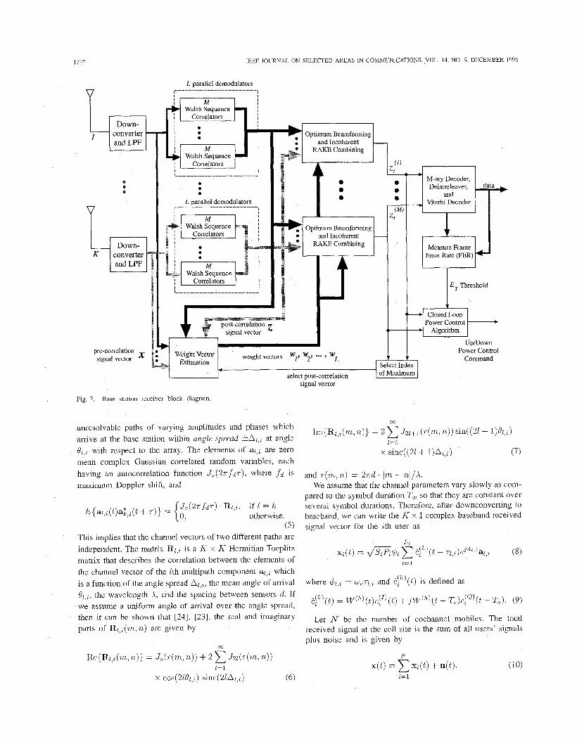
Fig. 2. Base station receiver block diagram.
unresolvable paths of varying amplitudes and phases which arrive at the base station within angle spread k&,, at angle Ql,% with respect to the array. The elements of ai,% are zero mean complex Gaussian correlated random variables, each having an autocorrelation function J , (Zr fdr ) , where fd is maximum Doppler shift, and
(5) This implies that the channel vectors of two different paths are independent. The matrix Rl,% is a K x K Hermitian Toeplitz matrix that describes the correlation between the elements of the channel vector of the Ith multipath component al,, which is a function of the angle spread A,,,, the mean angle of arrival Ql,%, the wavelength A, and the spacing between sensors d. If we assume a uniform angle of arrival over the angle spread, then it can be shown that [24], [23], the real and imaginary parts of Ri,,(m, n) are given by
and ~ ( m , n ) = 27rd. Im - nl/A. We assume that the channel parameters vary slowly as com-
pared to the symbol duration Tu, so that they are constant over several symbol durations, Therefore, after downconverting to baseband, we can write the K x 1 complex baseband received signal vector for the ath user as
L, xZ(t) = .!”(t - 7l,,)e”l tal,% (8)
1=1
where 4l,% = wcrl,% and E:h)(t) is defined as
&t) = W ( h ) ( t ) C ! I ) ( t ) +jW(”)( t - To)c,’Q’(t -To). (9)
Let N be the number of cochannel mobiles. The total received signal at the cell site is the sum of all users’ signals plus noise and is given by
N x( t ) = xz(t) + n(t). (10)
i = l

NAGUIB AND PAULRAJ: PERFORMANCE OF WIRELESS CDMA WITH At-ARY ORTHOGONAL MODULATION 1173
z cos(wct)
sin& t) t
v--------- W M
Fig. 3 . Correlators.
The vector n(t) = n,(t) + jn,(t) is the K x 1 additive Gaussian noise vector with zero mean and covariance
E{n(tl)n*(t2)) = s( t , - t 2 ) ( 1 1 )
where 0; is the noise variance per antenna.
111. RECEIVER MODEL
The block diagram of the base station antenna a m y receiver is shown in Fig. 2. It has a “Beamformer-RAKE’ structure where several multipath components are tracked in both time and space. After down-converting to baseband, the outputs of the LPF are fed into a bank of M Walsh correlators shown in Fig. 3. Assuming that the hth Walsh symbol was transmitted, where h = 1, . . . , M , the pre-correlation and post-correlation K x 1 signal vectors x( t ) and yj:) are used to estimate the channel vector al,i and the corresponding K x 1 optimum beamforming weight vector wl,; from the pre-correlation and post-correlation array covariances R,, and R,yy,l,i using the code filtering approach derived in [9] and [23]. The details of this algorithm and how R,, and R,,,l,; are tracked with the channel variation can be found in [23] and [25].
For each multipath component, we have M different post- correlation signal vectors y!;)5 11 = 1,. s . , M . The vectors yj,:) are fed to an optimum beamformer. The outputs of the
L; beamformers for the hth Walsh function w;,,y{(l’ are then fed into an incoherent RAKE combiner. The output of the incoherent RAKE combiner z!”) is the decision variable for the hth Walsh function. The beamformer and the incoherent RAKE combiner for the hth Walsh function are shown in Fig. 4.
In order to update the post-correlation array covariance Ryy,l,i (that will be used in estimating al,i and wl,i), the receiver needs the post-correlation vector yi;) corresponding to the true transmitted Walsh symbol W ( h ) ( t ) . However, at this stage the receiver has no prior knowledge of which post- correlation vector y[:’ is the right one. Here, the receiver relies on the inherent correlation of the multipath vector channel and the assumption that the channel remains almost constant over several symbol periods. In this case, the receiver uses a delayed update of Ryy,l,; (and hence delayed estimation of the channel vector and the optimum beamforming weight vector). This is done by using the decision on the cu-rrent Walsh symbol f~ to select the post-correlation vector y1(,’:) to update Ryy,l,i and obtain the optimum weight vector ~ 1 , ~ . This weight vector wl,; will be used for beamforming for the next symbol.
The decision variables z2(l), . . . , zjnr) at the output of the incoherent RAKE are then fed to an M-ary decoder, dein- terleaver, and Viterbi convolutional decoder. Without loss of

1774 IEEE JOURNAL ON SELECTED AREAS IN COMMUNICATIONS, VOL. 14, NO. 9, DECEMBER 1996
(4 2 Time Align
r2 Z2 I + 1 . 1
Fig. 4. Optimum beamforming and incoherent RAKE.
generality let us assume that the first user is the desired user and let r k , J be the time delay of the lcth tracked multipath which is assumed to be estimated perfectly and k = 1, . . . , L 1 .
the kth tracked multipath component for the first user as
transmitted
i = arg max (.in’). (18) Then, we can write the post-correlation signal vector yiy) for n=l, ,M
However, for the data, a symbol-by-symbol M-ary decoder is used [ 111. Both approaches yield exactly the same decisions for the M-ary symbol and both are optimal (i.e., a maximum likelihood rule) for an AWGN channel. Since the MA1 is not necessarily Gaussian, this decision rule is actually not optimal. However, when the number of cochaxhel users is large, the MA1 can be modeled as Gaussian noise and therefore this decision rule can be used. The primary reason for using the symbol-by-symbol approach for the data is to provide
y g = - x(t)Ep)* (t - r k , l ) d t (12)
(13)
(14)
- - d ( n ) + =
- - ,(n) k , l ’
k , l k , l , if if n # h
where
and de! is the desired signal vector, rntj is the MA1 signal vector, s t j is the self-interference (SI) signal vector due to other multipath components of the 1st user, and n t j is due to the AWGN. Let A, = a&. Also, for the kth tracked multipath let the optimum beamforming weights determined using the previously estimated Walsh symbol be w k , l . For an equal gain combining incoherent RAKE, the nth decision
improved performance with error-correcting codes by using soft decision decoding [ 101, [I 11.
Note also that we cannot use the output after the con- volutional decoding and deinterleaving to select the post- correlation signal vector. The reason for this is that we will have to wait for a decision to be made on the current symbol and convolutionally encode and interleave again. By the time this process is over (which is at least twice the time of one frame of bits), the channel would have changed and the estimated channel vector and the channel vector of the new symbol will be quite different. This will lead to a degradation in the beamformer output SINR.
IV. SIGNAL STATISTICS variable of the 1st user corresponding to the nth Walsh symbol is given by [IO]
In order to derive the uncoded bit error probability (BEP), L1 L1 we need to derive the statistics of the decision variables
k=l k=l in zb?!, i.e., the multiple access interference signal vector due to other cochannel users rntj, self-interference signal vector due to the user own multipath components and noise vector npj.
Xin) = z&) = I ~ ; , ~ Y C ? l 2 n = 1,. . . , M . (17)
Now, to select which post-correlation signal vector yil’ should be used in estimating the post-correlation array covariance Ryy,i,%, a hard decision is made on which Walsh symbol was
zl (1) , z1 (2 ) , . . . , z i M ) . First, we will examine the different terms
NAGUlB AND PAULRAJ: PERFORMANCE OF WIRELESS CDMA WITH M-AUY ORTHOGONAL MODULATION 1115
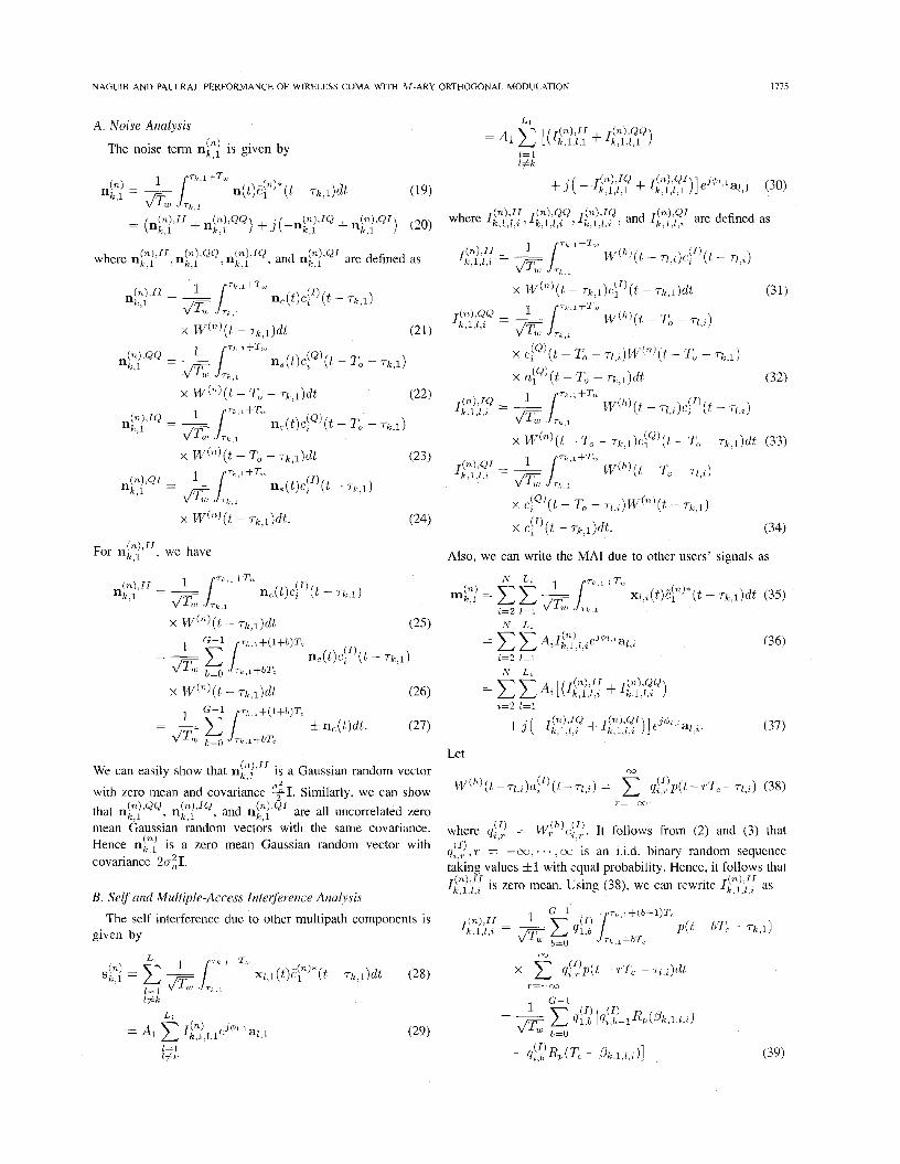
A . Noise Analysis
The noise term ng j is given by
For n t j i r r , we have
x Wn)(t - 71; 1 ) d t (26)
f ne(t)dt. (27) 1 G - l TI i + ( l + b ) T c
- -
E 2 .b l+bT,
We can easily show that ng;"' is a Gaussian random vector
with zero mean and covariance $1. Similarly, we can show that nF!lQQ, nt!"", and nt?'"' are all uncorrelated zero mean Gaussian random vectors with the same covariance. Hence nt! is a zero mean Gaussian random vector with covariance 2ai1.
B. Selj' and Multiple-Access Interference Analysis
given by The self interference due to other multipath components is
l j k
x ~ z ( ~ ) ( t - TO - ~ l , % ) W ( ~ ) ( t - ~ 1 )
x p ( t - T k , l ) d t . (34)
Also, we can write the MA1 due to other users' signals as
Let 00
W(h)( t - ~ i , ~ ) a : ' ) ( t - ~ 1 , ~ ) = q::)p(t - rT, - TI ,%) (38)
where q!? = W:h)c!f.!. It follows from (2) and (3) that -00, . * . , cc is an i.i.d. binary random sequence %,r
taking values 31 with equal probability. Hence, it follows that Ik,l,),z is zero mean. Using (38), we can rewrite ILy?,';: as
r=--00
( I ) ,T =
(n ) I I .

1116 IEEE JOURNAL ON SELECTED AREAS IN COMMUNICATIONS, VOL. 14, NO. 9, DECEMBER 1996
where P k , l , l , % = ~ 1 , ~ - Tk,J modulo-T, and Rp(s) is the partial auto correlation of the chip waveform defined as
Rp(s) = l s p ( i ) p ( i + T, - s )d t , 0 5 s 5 T,. (40)
For rectangular pulses, R p ( s ) = s. For asynchronous net- works, a reasonable assumption is that P k , l , l , % are independent and uniformly distributed over [0, T,]. Let
Using the results in [221, we can show that {Fb}b=o, ,G-I
are independent random variables and hence
Similarly, we can also show that Il;:,'zQl I&),'::, and Il::,'?' are all zero mean uncosselated random variables with the same variance given by (42).
Remark: In deriving the variance of Il:?,'{f, we used the assumption that the chip pulse shape is rectangular. In reality the channel is bandlimited (due to low pass filtering following the down converter) and the received signal cannot be a square wave. Under the condition that the same amount of energy is received regardless of the channel used, the received signal through a bandlimited channel will have a higher peak value, resulting in a higher level of MA1 interference due to larger fluctuations. In [19] and [22], it was shown that if the bandlimited channel has ideal low pass filter characteristics with a bandwidth B = l/T,, then, we would have
Similarly, covariance of n t j will then be
(43)
(44)
The total interference vector it! = rntj + st! is modeled as a zero mean complex Gaussian random vector with covari- ance I t ? = E{it?igj*}. Although, this assumption does not always hold for CDMA analysis, it was shown in [22] that it is valid for large G. Moreover, simulation results presented later in Section VI show that for large N . L, if we assume that the angles of arrival of the multipath components are uniformly distributed over the sector, the total interference vector iel will be spatially white. In this case
where a; is given by
r N 1
and C is a constant equal to two for a bandlimited channel and 2 for a rectangular pulse shape. For the remainder of our analysis we will assume the case of a bandlimited channel, i.e.,
C = 2. The covariance of the interference-plus-noise vector ut? is then given by
where a' = ~T,((T? + 0:).
C. Decision Statistics
Consider the pre-correlation and post-correlation signal vec- tors x(t) and y t i . With the assumption that the MA1 is spatially white, the optimum beamforming weights can be shown to be
where 5 is some arbitrary constant (that does not change the beamformer output SINR). For simplicity of the analysis, we
Define the beamformer output for the kth multipath com- set c = 1 I d m .
ponent of the first user WZ,~~F! as U::?
where lak,ll = ,/-. We can easily show that Vi:) = W ; , ~ U ~ ? is a zero mean complex Gaussian random variable with variance a'. For simplicity of notation, let L1 = L, Then, the decision variables for the first user are
From [lo], and conditioned on AI and al,ll 1 = 1,. . . , L , we can show that for n = h, z?' has a noncentral x2 distribution with 2L degrees of freedom and noncentrality parameter
1=3
The noncentrality parameter I is the symbol energy. For n # h, z?' has a x' distribution with 2L degrees of freedom. Therefore, we can write the conditional probability density function (pdf) of zi") as
where I L ( . ) is the modified Bessel function of the Lth order. r(.) is the Gamma function, and
& 7 s = 7.
(T (54)
We may recognize ys as the symbol energy to interference- plus-noise ratio.

NAGUIB AND PAULRAJ PERFORMANCE OF WIRELESS CDMA WITH M-ARY ORTHOGONAL MODULATION 1117
Remark: In this analysis, we used the assumption that the channel vector remains constant over two symbol periods. Also, we assumed that ak,l is estimated perfectly. In reality the channel is time varying and the array covariances are estimated using few samples. This will lead to errors in the estimated channel vector and hence a reduction in the symbol energy ys. In [25], we studied these losses as a function of the maximum Doppler shift f d and angle spread A. These results show that, with optimum forgetting factor for recursively estimating the array covariances, the loss in ys is less than a few tenths of a dB. Therefore, the analysis results obtained here can be regarded as an upper bound on the system performance.
v. PROBABILITY OF ERROR ANALYSIS
In this section we derive the uncoded BEP with hard decision. As we mentioned earlier, with forward error cor- rection (FEC) and interleaving, which is not considered in this paper, symbol by symbol soft decision decoding yields better performance. To derive the probability of error, without loss of generality, let us assume that h = 1, i.e., the first Walsh symbol W'(t) is transmitted. Then the probability of symbol error is
(57)
and
Finally, the corresponding uncoded BEP P ~ ( Y , ~ ) is given by
The symbol error probability and the corresponding uncoded BEP derived above are conditional probabilities and are func- tions of ys, which is itself a function of the channel vectors al , l , . . . , shadowing and path loss SI, and the first user transmitted power PI. Also note that because of power control (both open-loop and closed loop), P I , SI, and a1,l , . . . , a L , 1
are generally dependent variables. The dependency among these variables is in general a function of the maximum Doppler shift f d of the first user. A reasonable assumption is that the combination of open-loop and closed-loop power control is perfect in eliminating the slow fading due to shadowing and path loss [26]-[28]. Based on the mobile speed (or f d ) , we consider the following different cases.
A. Low Doppler Frequency
At low Doppler frequencies and high diversity orders, fast closed loop power control can eliminate most of the channel variation due to multipath fast fading. In the case of ideal power control, ys is a fixed quantity and is given by
(61)
where 7 is symbol energy to interference-plus-noise ratio per path per antenna. Also, the density function of z;"' for n = h given in (53) becomes an unconditional density. Therefore, the symbol error probability is
ys = 7. L . K
fir-1 L-1 1 2 1 03
P M = 1 - J' 11 -(?,I l ! 0 l=O 0
However, due to the delay in the control loop, finite step size by which the mobile can increase or decrease its power, and errors on the downlink, power control cannot be ideal (see, e.g., [28]). Therefore, the symbol error probability obtained above needs to be averaged over the probability density function of ys, which is not known in general. However, an approximation to the uncoded BEP can be obtained as follows. Here, we can use the approach in [29] and [20] to get an approximation for the uncoded BEP. First, let C, denote the &efficient of variation of ys, defined as
In [29] and [20], it is shown that for a low C,, (less than 0.3 [20]), a reasonable approximation of the symbol error probability is
A 2 1 1 P M FZ ipM(7s) + - ~ M ( ? s 6 + h0,) + -pAl(ys 6 - V%J7)
(64) where rs and cy are is the mean and variance of ys. We can see that c7 also represents the power control error. Then, the corresponding uncoded BEP is
B. High Doppler Frequency
For high Doppler frequency andlor long loop delay, the fading statistics of the received signal after power control remain the same as those of the multipath fast fading with only perfect average power control. In this case, we have
L
Ys = rC Iaz,1l2. (66) 1=1
The distribution of ys depends on the angle spread A through al,1. We consider the following three cases.
1) Small Angle Spread: For zero (or relatively small) an- gle spread A, the channel vector of the Zth multipath component can be expressed as
az,1 ?z ~ l , l V l , l (67)

1778 IEEE JOURNAL ON SELECTED AREAS IN COMMUNICATIONS, VOL. 14, NO. 9, DECEMBER 1996
where is a zero mean complex Gaussian random variable and for a ULA vl,1 is a Vandermonde vector [30] given by
V1,l = [1 e--3r=nf l l ,1D/X. . . e--3r=n@i,~D(K--1)/X T 1
(68)
In this case, we can show that ys has a x2 distribution with 2L degrees of freedom, i.e.,
Hence, it can be shown that the corresponding uncondi- tional pdf of z?’ for h = n is (see the Appendix)
2) Large Angle Spread: For large angle spread, the elements of al,l becomes uncorrelated and hence cl=, la1,1I2
is a sum of K L i.i.d. random variables having a x2 distribution with two degrees of freedom. Therefore, ys is distributed as a x2 random variable with 2KL degrees of freedom
L
The corresponding unconditional probability density function of for h = n is (see the Appendix)
where
(A’- 1) L - I 1
. (73)
3 ) Other Values of Angle Spread: For other values of A, we can easily show (see the Appendix) that the symbol energy to interference-plus-noise ratio is
Rl =
”(&) (&)
7, K
1=1 i=l
where U11 . . .GL,K are i.i.d. zero mean complex Gaussian random variables and rli = TXli, where {Al , i } i=l , , , , ,K are the eigenvalues of R I , ~ , the covari- ance matrix of the first mobile’s Zth multipath compo- nent. Let {Yli}l=l . . . ~ , i ...K be equal to {r;}i=1 ... K L . Also, we assume that the 7 1 ~ ’ s are distinct (this is true if the angles of arrival are sufficiently different). Then, ys is distributed as [lo]
where L K .
Z f k
and the corresponding unconditional pdf of z r ’ for h = n is (see the Appendix)
where ..L-2
and * denotes the convolution operation. Using the unconditional density of zi“’ for h = n in (70), (72), and (77), the average symbol error probability is given by
L-1 .
(79) Y . \ ” J u L 1=0
and the corresponding average uncoded BEP is given by (65).
VI. NUMERICAL AND SIMULATION RESULTS First, we study the accuracy of the approximation that the
MA1 signal vector can be assumed to be a spatially white complex Gaussian random vector. The base station receiver in Fig. 2 was simulated. In our simulation, we assumed that the processing gain G = 256, L = 4, N = 40, M = 64 and v = 0.375. We also assumed ideal power control. We assumed that the base station has three sectors, each with a five element ULA as shown in Fig. 5. The angles of arrival {e,,,} were assumed to be uniform over [O, 120”] (i.e., uniform over the sector). The angle spreads {Ak,,} were assumed uniform over [0,60°]. The results of 10 000 post-correlation signal vectors were used to estimate the statistics of the MA1 signal vector. Figs. 6 and 7 show the empirical PDF of both the I and Q component of the MA1 at the first antenna. From both figures we can see the validity of the Gaussian approximation. Also, the covariance matrix of the MA1 vector kc;,k,l was estimated and is shown at the bottom of the next page. The Frobenius norm [311 of the error IlellF = llRk’,k,l -111~ was estimated as 0.0058 which also shows that the MA1 can be assumed to be spatially white.
Next, we study the system uncoded BEP. The closed loop power control was simulated according to the model in [28] and [27]. In this simulation, we assumed that the mobile can increase/decrease its transmitted power by 0.5 dB at a time and that the power control command was sent every 6Tw. We assumed that the loop delay is also 6Tw and that the return channel error rate is 0.05. Figs. 8 and 9 show the power controlled signal level distribution versus the distribution of the simulated multipath Rayleigh fading at the RAKE output for f d = 5 and 100 Hz. From these two figures we can see that closed loop power control eliminates most of the channel variations at low Doppler freyuencies, while at high Doppler

NAGUIB AND PAULRAJ: PERFORMANCE OF WIRELESS CDMA WITH M - A R Y ORTHOGONAL MODULATION 1119
R!::/,k,l =
Fig. 5 . Simulation scenario.
! 1.0043 0.0062 + 0.0029i 0.0263 + 0.00041; 0.0212 + 0.0003.i 0.0204 + 0.0113i
0.0062 - 0.00292 1.0039 -0.0198 - 0.00061: 0.0090 + 0.00091: 0.0102 - 0.0027.i 0.0263 - 0.0004.1: -0.0198 + 0.00061: 1.0055 -0.0039 + O.OO1l. i 0.0111 - 0.0115.i 0.0212 - 0.00032 0.0090 - 0.00092 -0.0039 - 0.00111: 1.0055 -0.0156 + 0.0019.i
-0.0204 - 0.0113.i 0.0102 + 0.0027% 0.0111 + 0.0115.i -0.0156 - 0.0019i 1.0027
0.08
0.07
0.06
0.05
5 004
0.03
0.02
0.01
0.00 -20 -10 0 20
I~~erfeicrtcs Signal Lewl
Fig. 6. I-channel: first antenna interference distribution.
frequencies the received signal after power control has the same distribution as that of the simulated multipath fast fading. For more details on the power control performance of the above receiver, the reader is referred to [28].
For the ideal power control case, the probability of error was computed using (60) and (62). For the power control case with [(i = 5 Hz, the approximation in (64) was used. The resulting Pb is plotted for L = 4 and K = 1, K = 3, and K = 5 in Fig. 10. Note that this is independent of the angle spread A since with f d = 5 Hz, the fading is slow enough to be tracked by the power control loop for all values of A (3ee [28]). If we assume that the required uncoded BEP is then for K = 1 the maximum number of allowable users per sector N,,,, is 29 for ideal power control and 28 for power control with fcl = 5 Hz. For K = 3, these numbers go up to 85 and
0.08
0.07
0.06
0.05
E 004
0.03
0.02
0.01
n nn YtY"
-20 -10 0 10 20
Lntcrterctnce Signal Level
Fig. 7 . ()-channel: first antenna interference distribution.
-4 -2 0 2 4
Normalized Signal Level (dB)
Fig. 8. ing: f,, = 5 Hz, I< = 5, and L = 4.
Power-controlled signal distribution versus simulated multipath fad-
82, respectively. This shows the improved performance due to beamforming.
For the high f d case, as mentioned earlier, the distribution of ys, and hence the distribution of 2:"' for n = h, depends on the angle spread A. Fig. 11 shows the pdf of z p ' for different values of A and with ideal power control. From this figure we can see that the higher the angle spread is, the closer to the ideal power control case the pdf becomes. This can be explained as follows. At zero angle spread, the received signal in any multipath component will experience the same fading at all antennas and the antenna array will not provide any space

1780 IEEE JOURNAL ON SELECTED AREAS IN COMMUNICATIONS, VOL. 14, NO 9, DECEMBER 1996
1 0
0 9
0 8
0.1
0.0
-
-4 -2 0 2 4
Normalized Signal Level (dB)
Fig. 9. ing: fer = 100 Ha, I< = 5, and L = 4.
Power-controlled signal distribution versus simulated multipath fad-
1 0 2
8
! g 3 8"
0 10-3
a" 104
I 0-5 50 100 150 200
N, Number of Users
Fig. 10. ?!, for f C r = 5 Hz and closed loop power control.
diversity for this multipath component. As the angle spread increases, the signal fading at different antennas becomes more and more uncorrelated which leads to less variations in the RAKE output.
Figs. 12-14 show the uncoded BEP for A = Oo,A = 3", and A = 60" for a high maximum Doppler frequency f d
(high enough such that the statistics of the received signal after power control remain the same as those of the multipath fast fading). For A = 0" we can see that for P b = lop3 the maximum number of allowable users reduces to (compared to the perfect power control case) 10, 29, and 55 for K = 1,3, and 5 , respectively, which corresponds to a 65% reduction in system capacity. This capacity reduction is due to the multipath fading which was not eliminated by the closed loop power control.
With a single antenna, the statistics of ys does not depend on the angle spread. Therefore, the maximum number of allowable mobiles for K = 1 is the same at ten mobiles per cell for any value of angle spread. However, for angle spread A = 3" this number goes up to 44 and 90 mobiles
0 . 0 6 \ 8 I I I , I ~, , , , , , , , ,
0 20 40 60 80 100
Decision Variable q(')
Fig. 11. PDF of r$") for U = h at high fd,
w-t 7 7 1 I , , 1 I ! I I -I
--- I--- I I/ I ! I I B d l
A / I / I
I I __ 1 0 5
20 40 60 80 100 120 140 160 180 200
N, Number of Users
Fig 12 P b for high fd and A = O 0 , and power control
I O '
1 0 2
'I! G
2. 3 103
0
0
R
10 4
I / 1 I I I I I I 20 40 60 80 100 120 140 160 180 200
N, Number of Users
Fig. 13 for high f~ and A = 3 O , and power control.
for K = 3 and K = 5, respectively. This is due to the additional space diversity gain provided by the array. For

NAGUIB AND PAULRAJ: PERFORMANCE OF WIRELESS CDMA WITH M-ARY ORTHOGONAL MODULATION 1781
sented an approximation for the uncoded BEP as a function of the mean symbol energy to interference-plus-noise ratio and the power control error. For the case of high maxi- mum Doppler shift, we derived exact expressions for the uncoded BEP for different cases of angle spread. In all
10’
E 1 0 2
!z B
B 8 l o 3 spreads.
Y I cases, an improvement in system performance proportional
to the number of sensors is observed. Additional improve- 0
ment is obtained due to space diversity gain at high angle
a“ 10 4 APPENDIX
To derive the unconditional probability density functions in (70), (72), and (77), first we recall the characteristic function representation of the conditional density in (53) [lo] 106
20 40 60 80 100 120 140 160 180 200 N , Number of Users
Fig. 14. P b for high f d and A = GO’, and power control
Then the unconditional density of z p ) is given by TABLE I
PERCENT REDUCTION IN CAPACITY AT PtJ = lo-’ FOR HIGH f(,
Reduction at P b = lo-’ A = 0” A = 3” A = 60” K ~ T I I k l Y
1 38 50% SO% 50% 3 111 SO% 34.6% 19.6% 5 187 50% 26.5% 13.8%
TABLE I1 ~
PERCENT REDUCTION IN CAPACITY AT F‘b =
K ~ ~ , V , , , X
1 29 65 % 65.5% 65.5% 3 85 65.5% 48.8% 31.8% 5 142 65.5% 36.9% 21.0%
FOR HIGH fcl
Reduction at = l o p 2 A = 00 5 = 30 a = 600
A = GO”, these number goes even higher to 58 and 110, which is, again, due to the space diversity gain provided at large angle spreads. The results of Figs. 12-14 are summarized in Tables I and 11. These two tables give the % reduction in capacity at P b = lop2 and P b = lop3 relative to the case with ideal power control, respectively. We make the following observation. For a fixed angle spread, increasing the number of antennas will provide more space diversity gain. Similarly, for a fixed number of antennas, the larger the angle spread, the larger the space diversity gain provided by the array will be.
VII. CONCLUSION In this paper, we proposed an antenna array-based base
station receiver structure for DS/CDMA wireless systems with M-ary orthogonal modulation and studied its performance. We developed the vector multipath channel and received signal models. The‘ average uncoded BEP was evaluated as a function of the number of users, number of anten- nas, and angle spread for different power control scenar- ios. For the case of low maximum Doppler shift, we pre-
where Fys (.) is the characteristic function of ys. Then 1) For small angle spread, f,,(y) is given by (69) and
2) For large angle spread, f,, (y) is given by (7 1) and
Now we have
( K - 1 ) L
(84) - Rl
- ( s + 1/(a2(1+ 7 ) ) K L - L l=O

1782 IEEE JOURNAL ON SELECTED AREAS IN COMMUNICATIONS, VOL. 14, NO. 9, DECEMBER 1996
where
It follows that
3) For other values of angle spread, first we need to derive the density function for ys itself. We have
L
1=1
Let al,1 = RT,Pul where R z , ~ is the K x K covariance matrix of al,l and u1 is a K x 1 zero mean complex Gaussian random vector with covariance matrix I. Since R1,1 is Hermitian, we can rewrite R1,1 as
where U1 is an orthonormal matrix and A1 is a di- agonal matrix of the eigenvalues of R L , ~ . Let hl = diag(X11XL2 . . ‘ X ~ K } . Then we can write laL,1l2 as
i=l
where Ul = UTul is also a zero mean complex Gaussian random vector with covariance I. Then, we can rewrite Ys as
1=1 %=1
where 71% = ?XI, and, therefore, ys has the density function in (75). It follows that
xy(&)z&} z=o
where
REFERENCES
[ l ] D. L. Schilling, “Wireless communications going into the 21st century,” IEEE Trans. Veh. Technol., vol. 43, no. 3, pp. 645-652, Aug. 1994.
[2] A. M. Viterbi and A. J. Viterbi, “Erlang capacity of a power controlled CDMA system.” IEEE J . Select. Areas Commun., vol. 11. no. 6, pp. .. 892-900,-Aug. 1993.
r31 D. L. Schilling, “Broadband suread suectrum multiule access for -. . _ personal cellular communications,” in Proc. vTC’93, May 1993, pp. 8 19-822.
[4] K. S . Gilhousen, I. M. Jacobs, R. Padovani, A. Viterbi, L. A. Weaver, and C. Wheatly, “On the capacity of a cellular CDMA system,’’ IEEE Trans. Veh. Technol., vol. 40, no. 2, pp. 303-312, May 1991.
[5] S. Simanapalli, “Adaptive array methods for mobile communications,” in Proc. VTC’94, Stockholm, Sweden, June 1994.
[6] A. F. Naguib, A. Paulraj, and T. Kailath, “Capacity improvement with base-station antenna arrays in cellular CDMA,” IEEE Trans. Veh. Technol., vol. VT-43, no. 3, pp. 691-698, Aug. 1994.
[7] J. C. Liberti and T. S . Rappaport, “Analytical results for capacity improvement in CDMA,” IEEE Pans. Veh. Technol., vol. 43, no. 3, pp: 680-690, Aug. 1994.
181 S . C. Swales, M. A. Beach, D. J. Edwards, and J. P. McGeehn. “The . _ performance enhancement of multibeam adaptive base station antennas for cellular land mobile radio systems,” IEEE Tuum. Veh. Technol., vol. 39, no. 1, pp. 56-67, Feb. 1990.
[9] A. Naguib and A. Paulraj, “Performance of CDMA cellular networks with base-station antenna arrays,” in Proc. International Zui-ich Sem- inar on Digital Communications, Zurich, Switzerland, Mar. 1994, pp.
[lo] J . G. Proakis, Digital Communications, 2nd ed. New York: McGraw- Hill, 1989.
[11 J A. J. Viterbi, Principles of Spread Spectuum Multiple Access Communi- cations. Reading, MA: Addison-Wesley, 1995.
[12] G. Turin, “The effecrs of multipath and fading on the performance of direct-sequence CDMA systems,” IEEE J . Select. Areas Commun., vol.
[13] M. Kavehrad and B. Ramamurthi, “Direct-sequence spread spectrum with DPSK modulation and diversity for indoor wireless communica- tions,” IEEE Trans. Commun., vol. COM-35, no. 2, pp. 22&236, Feb. 1987.
[I41 M. M. J. Wang and L. B. Milstein, “Predetection diversity for CDMA indoor radio communications,” in Virginia Tech. Symposium on W i d e s s Personal Commun., Blackburg, VA, June 1992, pp. 13.1-13.10.
[15] A. F. Naguib and A. Paulraj, “Effect o f multipath and base-station antenna arrays on uplink capacity o f cellular CDMA,” in Proc. GLOBE- COM’94, San Fransisco, CA, 1994, pp. 395-399.
87-100.
SAC-2, pp. 597-603, July 1984.

NAGUIB AND PAULRAJ: PERFORMANCE OF WIRELESS CDMA WITH M-ARY ORTHOGONAL MODULATION 1783
1161 A. J . Viterbi, “Very low rate convolutional code for maximum theoretical performance of spread-spectrum multiple access channels,” IEEE J , Select. Areas Commun., vol. 8, no. 40, pp. 641-649, May 1990.
1171 K. I. Kim, “On the error probability of a DS/SSMA with a noncoherent AI-ary orthogonal modulation,” in Proc. VTC’92, Denver, CO, 1992, pp. 482485.
[18] Q. Bi, “Performance analysis of a CDMA cellular system,” in Proc. VTC’92, Denver, CO, 1992, pp. 483-486.
[I91 Q. Bi, “Performance analysis of a CDMA cellular system in the multipath fading environment,” in Proc. PIMRC’92, Boston, MA, 1992, pp. 108-111.
1 L. M. A. Jalloul and J. M. Holtzman, “Performance analysis of DS/CDMA with noncoherent AI-ary orthogonal modulation in multipath fading channels,” IEEE J . Select. Areas Commun., vol. 12, no. 5, pp. 862-870, Sept. 1994.
I Qualcomm Inc., Widehand Spread Spectrum Digital Cellular System, Apr. 1992, Proposed EIAKIA Interim Standard. D. J. Torrieri, “Performance of direct-sequence systems with long pseudonoise sequences,” IEEE J . Select. Areas Commun., vol. 10, no. 4, DD. 770-781. Mav 1992. A. F. Naguib, “Adapiive antennas for CDMA wireless networks,” Ph.D. dissertation, Stanford University, Stanford, CA, 1996. J. Salz and J. H. Winters, “Effect of fading correlation on adaptive arrays in digital mobile radio,” IEEE Trans. Veh. Technnl., vol. 43, no. 4, pp.
A. F. Naguib and A. Paulraj, “Recursive adaptive beamforming for wire- less CDMA,” in Proc. ICC’95. Seattle, WA, June 1995, pp. 1515-1519. A. Jalali and P. Mermelstein, “Effect of diversity, power control, and bandwidth on the capacity of microcellular CDMA systems,” IEEE J . Select. Areas. Commun., vol. 12, no. 5 , pp. 952-961, June 1994. S. Ariyavisitakul and L. F. Chang, “Signal and interference statistics of a CDMA system with feedback power control,” IEEE Trans. Commun., vol. 41, no. 11, pp. 1626-1634, Nov. 1993. A. F. Naguib and A. Paulraj, “Power control in wireless CDMA: Performance with cell site antenna arrays,” in Proc. GLOBECOM’YS, Singapore, 1995, pp. 225-229. J. M. Holtzman, “A simple, accurate method to calculate spread- spectrum multiple access error probabilities,” IEEE Trans. Commun., vol. 40, no. 3, pp. 461464, Mar. 1992. S. U. Pillai, Array Signal Processing. New York: Springer Verlag, 1989. G. H. Golub and C. F. V. Loan, Matrix Computations, 2nd ed. Balti- more, MD: John Hopkins University Press, 1989.
1049-1057, NOV. 1994.
Ayman F. Naguib was born on August 21, 1964, in Cairo, Egypt. He received the B S. degree (with hon- ors) and the M.S. degree in electrical engineering from Cairo University, Cairo, Egypt, in 1987 and 1990 respectively, and the M.S. degree in Statistics and the Ph.D. degree in electrical engineering from Stanford University, Stanford, CA, in 1993 and 1996, respectively.
From 1987 to 1989, he spent his military ser- vice at the Signal Processing Laboratory, Military Technical Collage, Cairo, Egypt. From 1989 to
1990, he was employed with Cairo University as a Research and Teaching Assistant in the Communication Theory Group. From 1990 to 1995, be was a Research and Teaching Assistant in the Information Systems Laboratory, Stanford University, Stanford, CA In 1996, he joined the Information Sciences Research Center of AT&T Labs, Murry Hill, NJ, as a Senior Member of Technical Staff. His current research interests include signal processing and coding for high speed wireless and digital communications and modem design for broadband systems.
Arogyaswami Paulraj (SM’85-F’91) attended the Naval Engineering College, India, and received the Ph.D. degree from the Indian Institute of Technol- ogy, New Delhi, in 1973
A large part of his career to date has been spent in research laboratories in India, where he supervised the development of several electronic systems His contnbutions include a sonar receiver (1973-1974), a surface ship sonar (1976-1983), a parallel computer (1988-1991), and telecommuni- cations systems. He has held visiting appointments
at several Universities, the Indian Institute of Technology, Delhi, from 1973 !o 1974, the Loughborough University of Technology, U.K., from 1974 to 1975, and Stanford University, CA, 1983 to 1986. His research has spanned several disciplines, emphasizing estimation theory, sensor signal processing, antenna array processing, parallel computer architectures/algorithms and com- munication systems. He is currently a Professor of Electrical Engineering at Stanford University working in the area of mobile communications. He is the author of about 90 research papers and holds several patents.
Dr. Paulraj has received a number of national awards in India for his contributions to technology development.