Himalayan Linguistics Lamkang verb conjugation - eScholarship
Upload
svuniversityCategory
view
0download
0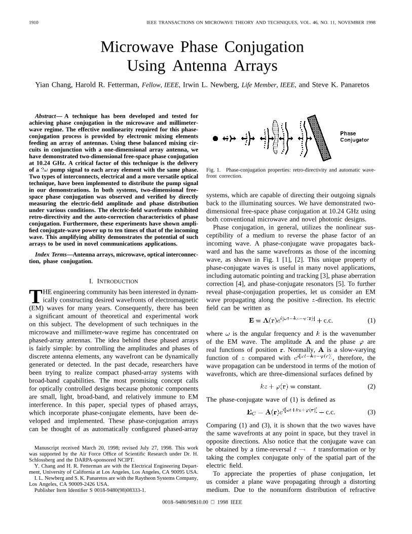
1910 IEEE TRANSACTIONS ON MICROWAVE THEORY AND TECHNIQUES, VOL. 46, NO. 11, NOVEMBER 1998
Microwave Phase ConjugationUsing Antenna Arrays
Yian Chang, Harold R. Fetterman,Fellow, IEEE, Irwin L. Newberg,Life Member, IEEE,and Steve K. Panaretos
Abstract—A technique has been developed and tested forachieving phase conjugation in the microwave and millimeter-wave regime. The effective nonlinearity required for this phase-conjugation process is provided by electronic mixing elementsfeeding an array of antennas. Using these balanced mixing cir-cuits in conjunction with a one-dimensional array antenna, wehave demonstrated two-dimensional free-space phase conjugationat 10.24 GHz. A critical factor of this technique is the deliveryof a 2! pump signal to each array element with the same phase.Two types of interconnects, electrical and a more versatile opticaltechnique, have been implemented to distribute the pump signalin our demonstrations. In both systems, two-dimensional free-space phase conjugation was observed and verified by directlymeasuring the electric-field amplitude and phase distributionunder various conditions. The electric-field wavefronts exhibitedretro-directivity and the auto-correction characteristics of phaseconjugation. Furthermore, these experiments have shown ampli-fied conjugate-wave power up to ten times of that of the incomingwave. This amplifying ability demonstrates the potential of sucharrays to be used in novel communications applications.
Index Terms—Antenna arrays, microwave, optical interconnec-tion, phase conjugation.
I. INTRODUCTION
T HE engineering community has been interested in dynam-ically constructing desired wavefronts of electromagnetic
(EM) waves for many years. Consequently, there has beena significant amount of theoretical and experimental workon this subject. The development of such techniques in themicrowave and millimeter-wave regime has concentrated onphased-array antennas. The idea behind these phased arraysis fairly simple: by controlling the amplitudes and phases ofdiscrete antenna elements, any wavefront can be dynamicallygenerated or detected. In the past decade, researchers havebeen trying to realize compact phased-array systems withbroad-band capabilities. The most promising concept callsfor optically controlled designs because photonic componentsare small, light, broad-band, and relatively immune to EMinterference. In this paper, special types of phased arrays,which incorporate phase-conjugate elements, have been de-veloped and implemented. These phase-conjugation arrayscan be thought of as automatically configured phased-array
Manuscript received March 20, 1998; revised July 27, 1998. This workwas supported by the Air Force Office of Scientific Research under Dr. H.Schlossberg and the DARPA-sponsored NCIPT.
Y. Chang and H. R. Fetterman are with the Electrical Engineering Depart-ment, University of California at Los Angeles, Los Angeles, CA 90095 USA.
I. L. Newberg and S. K. Panaretos are with the Raytheon Systems Company,Los Angeles, CA 90009-2426 USA.
Publisher Item Identifier S 0018-9480(98)08333-1.
Fig. 1. Phase-conjugation properties: retro-directivity and automatic wave-front correction.
systems, which are capable of directing their outgoing signalsback to the illuminating sources. We have demonstrated two-dimensional free-space phase conjugation at 10.24 GHz usingboth conventional microwave and novel photonic designs.
Phase conjugation, in general, utilizes the nonlinear sus-ceptibility of a medium to reverse the phase factor of anincoming wave. A phase-conjugate wave propagates back-ward and has the same wavefronts as those of the incomingwave, as shown in Fig. 1 [1], [2]. This unique property ofphase-conjugate waves is useful in many novel applications,including automatic pointing and tracking [3], phase aberrationcorrection [4], and phase-conjugate resonators [5]. To furtherreveal phase-conjugation properties, let us consider an EMwave propagating along the positive-direction. Its electricfield can be written as
c.c. (1)
where is the angular frequency and is the wavenumberof the EM wave. The amplitude and the phase arereal functions of position . Normally, is a slow-varyingfunction of compared with , therefore, thewave propagation can be understood in terms of the motion ofwavefronts, which are three-dimensional surfaces defined by
constant (2)
The phase-conjugate wave of (1) is defined as
c.c. (3)
Comparing (1) and (3), it is shown that the two waves havethe same wavefronts at any point in space, but they travel inopposite directions. Also notice that the conjugate wave canbe obtained by a time-reversal transformation or bytaking the complex conjugate only of the spatial part of theelectric field.
To appreciate the properties of phase conjugation, letus consider a plane wave propagating through a distortingmedium. Due to the nonuniform distribution of refractive
0018–9480/98$10.00 1998 IEEE

CHANG et al.: MICROWAVE PHASE CONJUGATION USING ANTENNA ARRAYS 1911
index , the incident wavefronts are no longer planarafter passing through the distorting medium. Equations(1) and (3) have shown that the conjugate wave has thesame wavefronts as those of the incident wave. It canbe proven the phase-conjugate wave satisfies Maxwell’sequations, therefore, it propagates backward as the time-reversed incident wave through both space and the distortingmedium and, consequently, the distortion is automaticallyremoved [2]. Another important feature of phase conjugationis that we only need to generate the conjugate fieldonone plane, this field will propagate backward and remainthe phase-conjugate field of everywhere [2]. This enablesthe possibility of accomplishing microwave and millimeter-wave phase conjugation using electronic-mixing phased-arrayantennas system.
To date, most of the phase-conjugation development hasbeen concentrated in the optical [visible and infrared (IR)]regime. Efforts to extend this technique to microwave andmillimeter-wave frequencies have encountered severe difficul-ties due to the small nonlinearity of natural materials and thelow-power density of sources at these frequencies. To examinethis problem, let us consider the phase-conjugation efficiencyof degenerate four-wave mixing (DFWM) [2] techniques. Ap-plying nominal parameters, this efficiency is lowered by about16 orders of magnitude as one tries to extend optical DFWMtechniques into microwave and millimeter-wave regime [6].This drastic efficiency loss presents severe difficulties formicrowave and millimeter-wave phase conjugation.
One possible solution for the above-mentioned efficiencyproblem is to increase the nonlinear susceptibility by many or-ders of magnitude. In the search for alternative nonlinear sub-stances suitable for the use in microwave and millimeter-wavephase conjugation, artificial Kerr media were found to havemuch larger nonlinearity than that of natural materials. Usingshaped microparticle suspensions [7] and microelectrome-chanical system (MEMS) structures [8], [9], volume gratingformation for microwave phase conjugation has been demon-strated with DFWM techniques. Although these artificial Kerrmedia have demonstrated as high as cm s /g [6],they have a number of intrinsic problems. Due to the re-quired movements of macroscopic particles in viscous fluid orpolyimide supported metal beams in air, these media sufferfrom slow response time and are sensitive to surroundingconditions. Therefore, these techniques are not suitable forpractical systems and applications.
II. A NTENNA-ARRAY APPROACH
Due to the above-mentioned difficulties in achieving mi-crowave phase conjugation using traditional DFWM tech-niques, this paper approaches the problem from a very differentperspective. Instead of using third-order nonlinear dipoles
, as in DFWM, electronic-mixing phased arrays are usedin a second-order three-wave mixing configuration to providea high artificial nonlinearity for generating phase-conjugatewaves. In this approach, microwave circuits, which combineantennas and mixers, effectively replace the roles of nonlineardipoles of a medium. The idea is to “sample” the incident
Fig. 2. First, the incident wavefront is sampled at different positions. Eachelement then generates a phase-conjugate current using microwave circuitry.This current will excite a phase-conjugate field at the sampling point. Thesuperposition of these fields becomes the phase-conjugate wave.
wave at different positions of the wavefront using antennaelements and then generate phase-conjugate currents usingmicrowave mixers. These currents will then excite a phase-conjugate field at each sampling point. The combined fieldof all the elements will be the phase-conjugate field of theincident beam. This sample-then-mix concept is shown inFig. 2. It was first proposed in the 1960’s, but due to the lack ofmodern semiconductor and photonic technologies, researchersdid not have practical ways to realize this concept [10], [11].
To understand how the conjugate signal can be generated ateach element using microwave circuitry, let us consider againthe incident wave shown in (1). At theth element of thearray, the incoming electric field is
c.c. (4)
where
(5)
The signal picked up by the antenna and then sent to themixer can be written as
c.c. (6)
Now consider a signal delivered to the local oscillator(LO) port of the mixer given by
c.c. (7)
This pump signal has to be delivered to all elements at thesame amplitude and phase; otherwise, the mixed output willcontain a term other than that depends on. If this everhappens, the sum of the excited field at each element will bedistorted and will not form the conjugate beam. Now, throughdifferent frequency generation in the mixer, the intermediatefrequency (IF) output contains a current component
(8)

1912 IEEE TRANSACTIONS ON MICROWAVE THEORY AND TECHNIQUES, VOL. 46, NO. 11, NOVEMBER 1998
This current component has the conjugate-phase insteadof the input phase , therefore, it will excite the conjugatefield at when delivered to the antenna
c.c. (9)
When the sampling spacing is less than , the combinedfield forms the phase-conjugate signalon the sampling surface. It has been discussed earlier that if aphase-conjugate field is generated on a plane, it will propagatebackward and be conjugate to the incident beam everywhere.Therefore, is the desired phase-conjugate field. In thepast three years, various groups have explored retro-directivephased arrays utilizing this concept [12], [13]. These studieshave concentrated on the retro-directive property of phaseconjugation. In this paper, we focus on wavefront propertiesand reconstruction, and also investigate optical interconnectionfor the pump signal so that large phase-conjugation arrayscan be constructed with less complexity.
There is an important issue we have to address here. Unlikeany of the traditional phase-conjugation techniques, whichutilize virtually infinite dipoles as far as our concern, this arrayapproach can only have a limited number of elements becauseof economic and engineering constraints. To clarify the effectscaused by a finite number of elements, the phase-conjugatewave of a dipole source has been calculated for three phase-conjugate arrays having different number of elements. Thefirst array was formed by eight elements, the second one by 40elements, and the third one by 200 elements. For the eight- and40-element arrays, the spacing between elements was chosento be . The 200-element array had a spacing of ,which was one-fifth of that of the 40-element array. Therefore,the 40-element array had five times the aperture size of theeight-element one, with the same sampling density. The 200-element array had the same aperture size as the 40-elementone, but with five times the sampling density. The antennaelements were assumed to have dipole radiation patterns andcollinear axes.
In the calculation, the center of each array was used asthe origin. The wavelength was assumed to be 3 cm, whichcorresponds to 10 GHz in frequency. Fig. 3 shows the con-jugate electric-field magnitude distribution generated by theeight-element array at a given time. It clearly exhibits retro-directivity, but does not show the conjugate beam focusingback to the source. This is caused by the diffraction effects of asmall aperture size. The conjugate electric-field distribution ofthe 40-element array is shown in Fig. 4. It demonstrates fairlywell wavefront reconstruction, as well as retro-directivity andfocusing can be clearly seen. The calculated conjugate fielddistribution of the 200-element array displays no perceivableimprovement over the 40-element one. Therefore, a samplingspacing slightly less than is acceptable for most cases. Ifthe spacing is greater than , grating sidelobes can developand, therefore, destroy the conjugate wavefront patterns.
From these comparisons, we have seen the main factordetermining that the resolution is not the sampling density(as long as it is greater than ), but the aperture size. If werequire the phase conjugator to have a high resolving power,equally spaced arrays with spacing, like the examples,
Fig. 3. The calculated conjugate electric-field magnitude distribution gen-erated by an eight-element array. Brighter areas represent higher field. Theelement spacing is0:467� and a dipole source is located at (57.9 cm, 15.6cm), as marked by the arrow. Only retro-directivity is observable in thisconfiguration because of diffraction effects.
Fig. 4. The calculated conjugate electric-field magnitude distributiongenerated by a 40-element array. The element spacing is0:467�. Bothretro-directivity and focusing can be clearly observed at this aperture size.
will not be practical, as the number of elements will be astro-nomical. For example, a resolving power of 10–10 radcould require 4 10 to 4 10 elements. However, usingrandomly distributed elements over the aperture to preventthe development of grating lobes can dramatically reduce thenumber of elements required in a sparse array [14].
III. ELECTRICAL-INTERCONNECTIONEXPERIMENTS
The concepts of microwave phase conjugation usingelectronic-mixing antenna arrays have been discussed in
CHANG et al.: MICROWAVE PHASE CONJUGATION USING ANTENNA ARRAYS 1913
Section II. To prove the feasibility of this approach, we havebuilt an array of eight phase-conjugate elements to demonstratethe generation of phase-conjugate waves. The equipment anddevices available to us limited the number of elements used inthis demonstration. Although an eight-element array would notbe able to focus a diverging incident beam back to its sourcedue to diffraction limitations (as calculated in Section II),it should exhibit retro-directivity and can demonstrate phaseautocorrection when a distortion medium is introduced into thebeam path. These two key characteristics of phase conjugationare strong evidences of the feasibility of this technique.
Since microwave components have relatively large loss,size, and weight, and are more susceptible to EM interference,we find that optical interconnection is the crucial technol-ogy for constructing large microwave phase-conjugate arrays.However, for an eight-element demonstration array, it is stillfeasible to build a system using straightforward microwaveinterconnects. Therefore, in this section, we will first discussthe construction and measurements of an electrically inter-connected phase-conjugate array. Its optically interconnectedcounterpart will be considered in Section IV.
As mentioned in Section II, each element of a phase-conjugate array will excite the conjugate field at its samplingposition via difference frequency generation. In an ideal el-ementary configuration, the sampled signal goes through acirculator into a low-noise amplifier. This amplifier providescompensation to the conversion loss of the mixing process inthe next step. It can also provide gain so that the conjugatesignal is more intense than the input one. After mixing withthe pump signal in a mixer, the output IF signal has theconjugate phase and it is sent back to the sampling antennathrough the circulator. In this configuration, the antenna hasto be very efficient. The reason is that any reflection ofthe conjugate signal from the antenna will go through thecirculator, as it were the sampled incident signal. This willaffect the phase of the output signal and, thus, destroy theconjugate-phase generation. If the reflection is large enough,the circuit will even start oscillating by itself. To study thismore closely, let us assume the return loss of the antennais , gain of the amplifier is and conversion loss of themixer is . , , and are complex output to input voltageratios to include the phase change at each stage. The circulatorand mixer are assumed to be perfect, no unwanted signalleakage between their ports. In order to generate the phase-conjugate wave, we require that the reflected conjugate signalbe much smaller than the sampled signal. This requirementcan be written as
(10)
and when , the system starts to oscillate.Commercial mixers normally have a conversion loss around
10 dB, which corresponds to . With a speciallydesigned narrow-band antenna array, a 30-dB return loss canbe achieved. This corresponds to . Equation(10) gives us . If we choose , thephase-conjugate signal will be ten times more powerful thanthe incident signal. Unfortunately, the antenna array avail-able to us had a return loss of about 7 dB at the desired
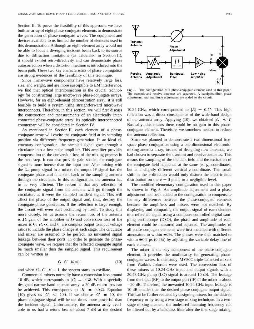
Fig. 5. The configuration of a phase-conjugate element used in this paper.The transmit and receive antennas are separated. A bandpass filter, phaseadjustment, and amplitude adjustment are added to the circuit.
10.24 GHz, which corresponded to . This highreflection was a direct consequence of the wide-band designof the antenna array. Applying (10), we obtained .Basically, this means there could be no gain in this phase-conjugate element. Therefore, we somehow needed to reducethe antenna reflection.
Since we planned to demonstrate a two-dimensional free-space phase conjugation using a one-dimensional electronic-mixing antenna array, instead of designing new antennas, wehad chosen to separate the transmit and receive antennas. Thismeans the sampling of the incident field and the excitation ofthe conjugate field happened at the same coordinates,but at a slightly different vertical -coordinate. This smallshift in the -direction would only disturb the electric-fielddistribution on the plane to a negligible level.
The modified elementary configuration used in this paperis shown in Fig. 5. An amplitude adjustment and a phaseadjustment had been added to the configuration to compensatefor any differences between the phase-conjugate elementsbecause the amplifiers and mixers were not matched. Bydisplaying and comparing the output signal of each elementto a reference signal using a computer-controlled digital sam-pling oscilloscope (DSO), the phase and amplitude of eachelement could be measured and adjusted. The amplitudes ofall phase-conjugate elements were first matched with differentattenuators to within 2%. The phases were then matched towithin 0.2 ps (0.2%) by adjusting the variable delay line ofeach element.
The mixer is the key component of the phase-conjugateelement. It provides the nonlinearity for generating phase-conjugate waves. In this study, MY50C triple-balanced mixersfrom Watkins–Johnson were used. The conversion loss ofthese mixers at 10.24-GHz input and output signals with a20.48-GHz pump (LO) signal is around 10 dB. The leakagefrom the input (RF) to the output port (IF) of the mixer is about
20 dB. Therefore, the unwanted 10.24-GHz input leakage is10 dB smaller than the desired phase-conjugate output signal.This can be further reduced by designing mixers for the desiredfrequency or by using a two-stage mixing technique. In a two-stage mixing element, the undesired incoming frequency canbe filtered out by a bandpass filter after the first-stage mixing.

1914 IEEE TRANSACTIONS ON MICROWAVE THEORY AND TECHNIQUES, VOL. 46, NO. 11, NOVEMBER 1998
Fig. 6. This setup is used to map out two-dimensional electric-field mag-nitude distribution. The receive horn is at a lower height than the transmithorns to prevent blocking of the incident beams. It can be moved to differentpositions to measure the electric-field strength.
This filtered signal can then be mixed in the second stage toproduce the final conjugate signal. Again, a second bandpassfilter can filter out any undesired leakage signals. This four-wave mixing technique can achieve higher isolation betweenthe incoming signal and the conjugate signal at the cost of anadditional pump source for each element. The details of thistechnique will be explained later.
To demonstrate microwave phase conjugation using theeight-element electronic mixing array, we prepared an electric-field mapping setup in an anechoic chamber, shown in Fig. 6.As mentioned earlier, the transmit and receive antennas ofthe conjugator were separated in the-direction (height) by1.4 cm. One or two transmit horns were used as illuminatingsources. Both transmit horns were 60 cm from the conjugator.This distance was chosen because of the sizes of the chamberand conjugator. The receive horn was mounted on a translationstage for radial movement. Its distance to the conjugatorwas varied at 0.5 cm intervals from cm tocm. The translation stage itself was mounted on a steppingmotor stage for angular control. A computer controlled therotation stage at 1 intervals from to .The signal detected by the receive horn was proportional tothe electric field at that point and was amplified and thendisplayed on a DSO. By comparing the received signal toa reference signal using a computer, the amplitude and phaseof the electric field at the receiving horn position could beaccurately measured.
In the first set of measurements, only one transmit hornwas used as the source. It was placed at . This anglewas chosen for convenience, it could be varied between30to 30 . The conjugate electric-field distribution is shown inFigs. 7 and 8, labeled as “without distortion.” In the contourplot of Fig. 7, gray scale is used to represent the magnitude ofthe electric field. The black dot next to the plot is the sourcelocation. The phase-conjugate array is located on the left ofeach plot and the tick mark labels are in centimeters. Thewavefronts of the conjugate wave can be seen clearly, and aretraveling from left to right. Although the focusing effect cannotbe observed because of the diffraction limits, retro-directivityis certainly demonstrated. In the surface plot of Fig. 8, theelectric-field magnitude is represented by the height at a given
Fig. 7. The contour plots of the measured phase-conjugate electric field ofa source at+15�, as marked by the black dots. The high-contrast areasrepresent the conjugate beams, and the faint fringes are due to leakage. Theydemonstrate retro-directivity and automatic phase correction when a distortingmedium is inserted in front of the conjugator.
point. The white dot on the zeroth-field plane marks the sourceposition. The smaller bumps in this figure were caused mainlyby the amplified incident signals leaking through the mixers.This amplitude of the electric field was about one-third to one-fourth of that of the conjugate beam. This means the leakagepower was about 10 dB of the conjugate power, as mentionedearlier in this section.
Our next step was to demonstrate automatic phase correc-tion. This was achieved by inserting a distorting medium infront of the phase conjugator. We used a piece of Plexiglas asthe distorting medium. The conjugate electric field is shownin Figs. 7 and 8, labeled as “with distortion.” By comparingthe fringes of the two plots in Fig. 7, the wavefronts of theconjugate beam remained the same shape and phase with orwithout the distortion, as the theory predicted. The leakagewavefronts were distorted when the distorting medium waspresent. In Fig. 8, the leakage bumps were again destroyedby the distortion, while the phase-conjugate beam maintainedits phase and amplitude. These results unambiguously demon-strate the retro-directivity and automatic phase correctionability of this microwave phase conjugation.
In order to reveal the automatic phase correction morequantitatively, the receive horn was placed in the conjugatebeam at 55 cm from the conjugator. The electric field versustime was recorded and then compared with and without thedistortion. The phase difference in time was less than 1 psfor a distorting medium capable of 25-ps one-way delay. Tofurther demonstratethat the phase-conjugate beam does carrya negative incident phase, we moved the distorting mediumto cover the source only. Therefore, only the incident beamwent through the distortion. The electric-field distribution is

CHANG et al.: MICROWAVE PHASE CONJUGATION USING ANTENNA ARRAYS 1915
Fig. 8. The surface plots of the phase-conjugate electric field of a source at+15�, as marked by the white dots. They show retro-directivity and automaticphase correction. The smaller bumps are caused by amplified leakage and are destroyed by the distortion.
Fig. 9. This data is taken with the distorting medium covering only thetransmit horn. The conjugate beam now has advanced wavefronts, while thereflected beam is distorted and has retarded wavefronts.
shown in Fig. 9, labeled as “with distortion.” Due to theexistence of the distorting medium, the phase of the incidentbeam was retarded by . If this signal was leakage, itwould carry the same phase retardation . However, ifthe incident beam was phase-conjugated by the conjugator,the phase of the conjugate beam would be , whichmeans its phase was advanced by. This theory is shownin Fig. 9 as the conjugate wavefronts moved toward thesource (advanced phase), while the leakage wavefronts moved
toward the conjugator (retarded phase). Also noticeable inFig. 9, the leakage beam was deflected away from the centerbecause of the distortion. This shows the Plexiglas did actas an effective distorting material and further confirms theprevious experiments.
IV. OPTICAL-INTERCONNECTIONEXPERIMENTS
As mentioned earlier, electrical interconnection will not beable to handle a large two-dimensional phase-conjugate arrayfor complete three-dimensional wavefront reconstruction. Theproblems in the electrical scheme are due to the high loss,heavy weight, and large size of microwave and millimeter-wave components. It is also more susceptible to EM interfer-ence. In contrast, using optical interconnection, thepumpsignal can be delivered to all elements with very little loss( 0.3 dB/Km) at very high density (e.g., 1 element/millimeterfor millimeter-wave arrays). Therefore, in this paper, wepropose and demonstrate the optical-interconnection techniqueto address these electrical-interconnection problems.
In this optical-interconnection scheme, the eight phase-conjugate elements were the same as in the electrical con-figuration shown in Fig. 5. A Lightwave 122 diode-pumpedNd:YAG laser was used as the light source. The opticalwavelength was at 1319 nm, with a linewidth5 KHz. Thiswavelength was chosen to minimize the dispersion in opticalfiber systems. In our demonstration, it was not an importantissue because of the relatively short propagation distances.However, to be able to extend this technique into large arraysand/or millimeter-wave frequencies, minimized dispersion willbe a crucial factor.
The laser light was directed into a Mach–Zehnder opti-cal modulator using a polarization preservation fiber. Themodulator was biased at its transfer function halfway pointfor optimal linear modulation. The 10.24-GHz signal was
1916 IEEE TRANSACTIONS ON MICROWAVE THEORY AND TECHNIQUES, VOL. 46, NO. 11, NOVEMBER 1998
frequency-doubled to 20.48 GHz, amplified, and then used tomodulate the laser light. A more interesting way to modulatethe light at is to bias the modulator at its transfer functionminimum and apply an signal to its RF electrode. Due tothe nonlinearity of the transfer function at the minimum, theoptical power varies at as desired. The advantage of thistechnique is that no microwave frequency-doubler is required.The disadvantage is that it is very sensitive to the bias ofthe transfer function. Even small fluctuations will result inloss of modulation efficiency and unwanted linear modulation.Therefore, the bias point has to be monitored closely by afeedback loop.
This modulated light can now be delivered tophotodetector-attached phase-conjugate elements, which maybe far away for a large array or close together for highoperating frequencies. In this paper, this 20.48-GHz modulatedlight entered an 1 8 optical power splitter and split into eightequal-intensity equal-phase signals. The 20.48-GHz pumpsignal was then extracted by a p-i-n diode at each element.This pump signal was amplified to a power level of 9 dBm, andthen fed to the phase-conjugate element, as in the electricallyinterconnected system.
Using the experimental setups and procedures mentionedearlier, the output amplitudes of these eight elements werematched to within 6% and their phases were matched towithin 0.2 ps (0.2%). After this calibration, we were ableto demonstrate two-dimensional microwave phase conjugationusing the optically interconnected electronic-mixing array. Allthe tests performed in the electrical demonstration have beensuccessfully duplicated.
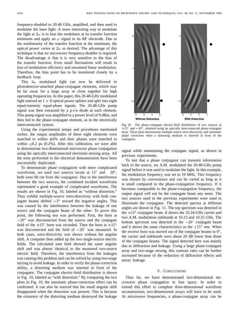
To demonstrate phase conjugation with more complicatedwavefronts, we used two sources locate at 15and 20 ,both were 60 cm from the conjugator. Due to the interferencebetween the two sources, the combined incident wavefrontsrepresented a good example of complicated wavefronts. Theresults are shown in Fig. 10, labeled as “without distortion.”They exhibit multiple-source retro-directivity with both con-jugate beams shifted 3 toward the negative angles. Thiswas caused by the interference between the leakage of onesource and the conjugate beam of the other. To prove thispoint, the following test was performed. First, the horn at
20 was disconnected from the source and the conjugatefield of the 15 horn was recorded. Then the horn at15was disconnected and the field of20 was measured. Inboth cases, retro-directivity was shown without the angularshift. A computer then added up the two single-source electricfields. The calculated sum field showed the same angularshift and was almost identical to the measured two-sourceelectric field. Therefore, the interference from the leakageswas causing this problem and can be solved by using two-stagemixing to avoid leakage. In order to verify the phase-correctionability, a distorting medium was inserted in front of theconjugator. The conjugate electric-field distribution is shownin Fig. 10, labeled as “with distortion.” By comparing the twoplots in Fig. 10, the automatic phase-correction effect can beconfirmed. It can also be noticed that the small angular shiftdisappeared when the distortion was present. This is becausethe existence of the distorting medium destroyed the leakage
Fig. 10. The phase-conjugate electric-field distribution of two sources at+15� and�20�, obtained using an optically interconnected phase-conjugatearray. These plots demonstrate multiple-source retro-directivity and automaticphase correction when a distorting medium is inserted in front of theconjugator.
signal while maintaining the conjugate signal, as shown inprevious experiments.
To test that a phase conjugator can transmit informationback to the source, we A.M. modulated the 20.48-GHz pumpsignal before it was used to modulate the light. In this example,the modulation frequency was set to 10 MHz. This frequencywas chosen by convenience and can be varied as long as itis small compared to the phase-conjugation frequency. If itbecomes comparable to the phase-conjugation frequency, theoutput signal will not be the conjugate beam any more. Thetwo sources used in the previous experiments were used toilluminate the conjugator. The detected spectra at differentangles are shown in Fig. 11. The top spectrum was detected inthe 15 conjugate beam. It shows the 10.24-GHz carrier andtwo A.M. modulation sidebands at 10.23 and 10.25 GHz. Thebottom spectrum was detected in the20 conjugate beamand it shows the same characteristics as the15 one. Whenthe receive horn was moved out of the conjugate beams to 0,the carrier and sidebands were about 20 dB lower than thoseof the conjugate beams. The signal detected here was mainlydue to diffraction and leakage. Using a large phase-conjugatearray and two-stage mixing, this contrast ratio can be furtherincreased because of the reduction of diffraction effects andmixer leakage.
V. CONCLUSIONS
Thus far, we have demonstrated two-dimensional mi-crowave phase conjugation in free space. In order toextend this effort to complete three-dimensional wavefrontreconstruction, two-dimensional arrays will have to be used.At microwave frequencies, a phase-conjugate array can be

CHANG et al.: MICROWAVE PHASE CONJUGATION USING ANTENNA ARRAYS 1917
Fig. 11. Detected spectra at different angles with a modulation on the pump signal. This demonstrates that retro-directivity can also be used to communicatebetween a conjugator and its illuminating sources. The top curve and bottom curve represent the two conjugate beams. The leakage signal between theconjugate beams is about 20 dB smaller than the conjugate beams. These spectra have been moved in the vertical direction for easier comparison.
constructed using discrete components, as done in this paper.As we have demonstrated, optical interconnections can solvethe pump signal distribution problem for large two-dimensional arrays. However, in the millimeter-wave regime,monolithic design will be needed in order to satisfy the small
spacing requirement. Using high-speed photodetectorsand mixing devices [15], [16] in conjunction with on-wafer polyimide optical waveguides [17], two-dimensionalmillimeter-wave phase-conjugate surfaces can be realized.Fig. 12 shows this concept.
To address the problem of amplified leakage signals comingout from our phase-conjugate elements, a two-stage mixingtechnique has been proposed [11]. To understand how it works,let us consider that the sampled incident signal has a phasefactor of . This incident signal will be mixed with apump signal having a phase factor of, whereand this phase factor is the same for all elements. After thefirst-stage mixing, there will be four major components comingout from the mixer: , , , and .The first term is the signal we want because of its reversedphase . The second term is the sum frequency, and thelast two terms are the leakage through the mixer. Since thesefour signals are at different frequencies if , a bandpassfilter at can be used to remove the three unwantedcomponents. A second-stage mixing is needed because thesignal carrying the conjugate phase is not yet at the incidentfrequency. To convert the signal back to frequency
, it is mixed with a second pump signal . Again,this pump signal has to be the same for all elements. As in
Fig. 12. Monolithic one-dimensional arrays forming a two-dimensional ar-tificial nonlinear surface for generating three-dimensional microwave phaseconjugation.
the first stage, four components will appear on the output port:, or , ,
and . Using a second bandpass filter at frequency, only the conjugate signal will be radiated back to
form the conjugate beam. Therefore, this two-stage mixingscheme can eliminate the leakage problems caused by thesingle-mixer approach, and has the advantage of never dealingwith frequencies as high as .

1918 IEEE TRANSACTIONS ON MICROWAVE THEORY AND TECHNIQUES, VOL. 46, NO. 11, NOVEMBER 1998
There are still other sources which can contribute to theoutput phase error, namely, the leakage of circulators andreflection of antenna elements. In this paper, we solved thisproblem by separating the sampling and radiating antennas.For a true three-dimensional wavefront reconstruction setup,sampling and radiating should occur at the same point and,therefore, only one antenna is desired. Both circulator leakageand antenna reflection can be reduced to below 30 dB if theyare specially designed for a specific narrow band. Also, forpulsed applications, wide-band operations can still be realizedif the sampled signal and conjugate signal can be separated intime. This can be achieved by delaying the conjugate signalin a long optical fiber during the sampling period. During theradiating period, the mixer input is blocked and, therefore, thereflected conjugate signal will not enter the mixer.
In this paper, we have concentrated on generating phaseconjugation using electronic-mixing arrays. This techniquecan also be extended to other nonlinear optics analogies.For example, by replacing the pump signal feeding themixer in a phase-conjugate element with the sampledsignal,the element can generate , therefore, acting as a second-harmonic element. This type of electronic mixing arrays canperform free-space second-harmonic generation. Using differ-ent configurations for the basic elements, these electronic-mixing microwave arrays can provide very high effectiveor , which are not available in any natural material.
Due to the retro-directivity and automatic phase correctionproperties, microwave and millimeter-wave phase conjuga-tion is useful in applications requiring automatic pointingand tracking and phase aberration corrections. We have alsodemonstrated that information can be transmitted in phase-conjugate signals without prior knowledge of where the targetsare. Therefore, microwave and millimeter phase conjugationcan be very useful for novel communications systems such assatellite links on moving vehicles and deep-space transponderapplications. Another interesting application is to use thesestructures to combine the output power from many elementsto form high-power beams with excellent mode quality.
In this paper, we have developed and demonstrated a newapproach to achieve phase conjugation in the microwaveand millimeter-wave regime. We have obtained similar re-sults for both electrical and optical-interconnection techniques.The proof of two-dimensional free-space phase conjugationhas been obtained by direct measurements of the outputelectric-field magnitude distribution at 10.24 GHz. Usinga distorting medium and two sources, retro-directivity andautomatic phase correction have been directly observed onthe electric-field wavefronts. The capability of data com-munication using phase conjugation has also been validatedby transmitting a 10-MHz modulated signal back to thetwo sources illuminating the conjugator. Furthermore, theconjugate signal has shown a 10-dB power gain, which isdesired for communications applications. In the near future,we foresee many nonlinear optical techniques being extendedto the microwave and millimeter-wave regime and also newmicrowave and millimeter-wave applications being developedusing these electronic mixing arrays.
ACKNOWLEDGMENT
The authors would like to thank Prof. R. W. Hellwarth,Univeristy of Southern California, Los Angeles, for his valu-able suggestions, and M. Espiau, University of California atLos Angeles, Center for High Frequency Electronics, for histechnical assistance.
REFERENCES
[1] A. Yariv and P. Yeh,Optical Waves in Crystals. New York: Wiley,1984.
[2] B. Ya. Zel’dovich, N. F. Pilepetsky, and V. V. Shkunov,Principles ofPhase Conjugation. Berlin, Germany: Springer-Verlag, 1985.
[3] Y. I. Kruzhilin, “Self-adjusting laser-target system for laser fusion,”Sov.J. Quantum Electron,vol. 8, no. 3, pp. 359–363, 1978.
[4] D. M. Pepper and A. Yariv, “Compensation for phase distortions innonlinear media by phase conjugation,”Opt. Lett., vol. 5, no. 2, pp.59–60, 1980.
[5] J. A. Yeung, D. Fekete, D. M. Pepper, and A. Yariv, “A theoreticaland experimental investigation of the modes of optical resonators withphase-conjugate mirrors,”IEEE J. Quantum Electron.,vol. QE-15, pp.1180–1188, Oct. 1979.
[6] R. Shih, “Microwave phase conjugation in an artificial Kerr medium,”Ph.D. dissertation, Dept. Elect. Eng., Univ. California at Los Angeles,Los Angeles, CA, 1991.
[7] R. Shih, H. R. Fetterman, W. W. Ho, R. McGraw,et al., “Microwavephase conjugation in a liquid suspension of elongated microparticles,”Phys. Rev. Lett.,vol. 65, no. 5, pp. 579–582, 1990.
[8] B. Tsap, K. S. J. Pister, and H. R. Fetterman, “MEMS orientationaloptomechanical media for microwave nonlinear applications,”IEEEMicrowave Guided Wave Lett.,vol. 6, pp. 432–434, Dec. 1996.
[9] , “Grating formation in orientational optomechanical media at mi-crowave frequencies,”Appl. Phys. Lett.,vol. 70, no. 18, pp. 2475–2477,1997.
[10] C. C. Cutler, R. Kompfner, and L. C. Tillotson, “A self-steering arrayrepeater,”Bell Syst. Tech. J.,vol. 42, pp. 2013–2032, 1963.
[11] E. L. Gruenberg, H. P. Raabe, and C. T. Tsitsera, “Self-directionalmicrowave communication system,”IBM J. Res. Develop.,vol. 18, no.2, pp. 149–163, 1974.
[12] C. Pobanz and T. Itoh, “A conformal retrodirective array for radarapplications using a heterodyne phased scattering element,” inProc.IEEE MTT-S Int. Microwave Symp. Dig.,vol. 2, Orlando, FL, May1995, pp. 905–908.
[13] S. L. Karode and V. F. Fusco, “Novel retrodirective beam formationtechniques,” inProc. 27th Microwave Conf.,vol. 1, Jerusalem, Israel,Sept. 1997, pp. 81–85.
[14] B. D. Steinberg,Principles of Aperture and Array System Design:Including Random and Adaptive Arrays.New York: Wiley, 1976.
[15] D. C. Scott, D. V. Plant, and H. R. Fetterman, “60 GHz sources usingoptically driven heterojunction bipolar transistors,”Appl. Phys. Lett.,vol. 61, no. 1, pp. 1–3, 1992.
[16] D. Bhattacharya, P. S. Bal, H. R. Fetterman, and D. Streit, “Opticalmixing in epitaxial lift-off pseudomorphic HEMT’s,”IEEE Photon.Tech. Lett.,vol. 7, pp. 1171–1173, Oct. 1995.
[17] D. P. Prakash, D. V. Plant, H. R. Fetterman, and B. Jalali, “Opticallyintegrated millimeter wave systems,”Proc. SPIE—Int. Soc. Opt. Eng.vol. 2153, pp. 101–110, 1994.
Yian Chang received the Ph.D. degree in physics from the University ofCalifornia at Los Angeles (UCLA), in 1996.
He is currently working at the Center for High Frequency Electronics,UCLA, as a Post-Doctoral Researcher, where his work has concentrated on theareas of microwave and millimeter phase conjugation and optically controlledphased-array radars.

CHANG et al.: MICROWAVE PHASE CONJUGATION USING ANTENNA ARRAYS 1919
Harold R. Fetterman (SM’81–F’90) received the Ph.D. degree from CornellUniversity, Ithaca, NY, in 1967.
He is currently a Professor in the Department of Electrical Engineering,University of California at Los Angeles (UCLA). He joined UCLA after14 years at the Lincoln Laboratory, Massachusetts Institute of Technology(MIT), Cambridge, where he was active in submillimeter-wave/millimeter-wave detectors and source programs. He successfully developed heterodynereceivers and solid-state sources with applications in plasma diagnostics,remote sensing, and radar modeling. Since joining UCLA, he has concentratedon millimeter-wave GaAs and InP devices and the optical control and testingof high-frequency systems.
Dr. Fetterman is a fellow of the Optical Society of America (OSA).
Irwin L. Newberg (S’53–A’54–M’59–LM’95) received the B.S. degree inelectrical engineering from the University of Cincinnati, Cincinnati, OH, in1953, and the M.S. degree from the Massachusetts Institute of Technology(MIT), Cambridge, in 1959.
Since 1965, he has been with the Hughes Aircraft Company (now RaytheonSystems Company), Los Angeles, CA, where he has been involved in radar-system engineering and, for the past ten years, in the application of high-speeddigital and microwave fiber-optic links for radar systems.
Steve K. Panaretos, photograph and biography not available at the time ofpublication.
Copyright © 2022 FDOKUMEN


![Patch Antenna[1]](https://static.fdokumen.com/doc/165x107/63158e4cc32ab5e46f0d5c89/patch-antenna1.jpg)