Final Report The New York University Concourse Project
271
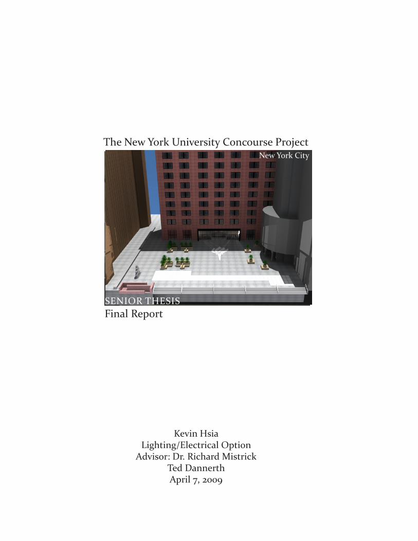
Kevin Hsia Lighting/Electrical Option Advisor: Dr. Richard Mistrick Ted Dannerth April 7, 2009 SENIOR THESIS Final Report The New York University Concourse Project New York City
-
Upload
khangminh22 -
Category
Documents
-
view
0 -
download
0
Transcript of Final Report The New York University Concourse Project
Kevin HsiaLighting/Electrical Option
Advisor: Dr. Richard MistrickTed DannerthApril 7, 2009
SENIOR THESIS Final Report
The New York University Concourse ProjectNew York City

Executive Summary
The senior thesis project consists a technical analysis on the New York University Concourse Project. As part of the Architectural Engineering curriculum at Pennsylvania State University, the yearlong thesis analyzed the lighting and electrical systems for four spaces. In addition, two breadth topics in the field of architecture and mechanical systems were investigated. Furthermore, to fulfill the requirements of the Master of Architecture Engineering degree, a master depth study in daylighting was evaluated.
The New York University Concourse Projects involves the renovation of Tisch, Shimkin, and the Kaufman Center. Of the three buildings, Tisch Hall was the main focus of study. The lighting in-depth study was guided by the recommendations from the IESNA Handbook and ASHRAE Standard 90.1. The overall design concept addresses the four areas of consideration formulated from interviews with NYU students. The four objectives are: strengthening the pride of New York University, cognitive health, way-finding/orientation, and physical heath. The four redesigned spaces accommodated the four considerations.
The electrical depth addressed adjustments in the electrical system based on the new lighting design. Further studies in overcurrent protective device, photovoltaic system feasibility, and backup generator design were conducted.
The two breadth studies involved the construction of a water harvest system and outdoor seating system for the plaza. In terms of the master depth study, a daylighting analysis was performed in the lobby of Tisch Hall.

Table of Contents Introduction1 Building Stat
Lighting Depth4 Gould Plaza22 Tisch Lobby39 Classroom60 MBA Student Lounge
Electrical Depth73 Gould Plaza Electrical Design78 Tisch Lobby Electrical Design84 Classroom Electrical Design90 MBA Student Lounge Electrical Design94 Backup Generator Study100 Photovoltaic Feasibility Study Breadth Study118 Outdoor Plaza Seating System128 Water Harvest System Study
Master Depth Study139 Daylighting in Tisch Hall Lobby
156 Summary and Conclusion
157 Acknowledgements
158 References
159 Appendix A - Luminaires B - Lamps C - Ballasts D - Lighting Controls E - Backup Generator F - Photovoltaic Panels G - Overcurrent Protection Device H - Water Harvest System I- Lighting & Electrical Drawings

Final Report
Building Statistics
Page
kevin hsia | nyu concourse project
Building Stat
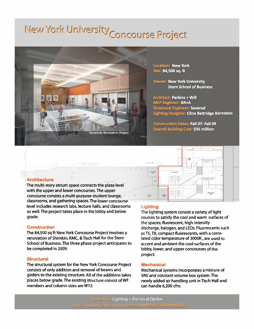
Project: New York University Concourse ProjectLocation and Site: 44 West 4th Street, New York, NY 10012 Building Occupant Name: Education/UniversitySize: 70,000 sq.ftNumber of stories above grade: 1 story above grade, 2 below gradeOwner: New York University Stern School of BusinessArchitect: Perkins + Will MEP Engineer: BR+AStructural Engineer: SeverudConstruction Dates: Fall 07 - Fall 09Overall Building Cost: $35 millionProject Delivery: Design Bid Build
ArchitectureThe project consists of a multi-story atrium space that connects the plaza level with the upper and lower concourses. In the building, there are multi-purpose student lounges, classrooms, and gathering spaces. The lower concourse level includes research labs, lectures, and classrooms as well.
CodesNYC Building Code 2004 and NFPA Life Safety 101
Zoning Residential District
Historical Requirements of Building The building falls under the New York City Landmarks Law which is concerned with the preservation of the city’s architectural, historical, and cultural heritage buildings. The construction for the NYU Concourse Project will deal with reconstructing the interior spaces.
Building Envelope The project spans across three buildings (Tisch, KMC, Shimkin). All of the renovation and construction takes place under the existing three buildings. A newly constructed skylight on Gould Plaza will provide natural daylight into the upper concourse. Newly constructed wall systems and glass walls will be incorporated into the existing system.
1

Final Report
Building Statistics
Page
kevin hsia | nyu concourse project
Construction The 70,000 sq. ft. New York Concourse Project involves an interior renovation of the upper and lower concourses of Tisch Hall, KC, and Shimkin. The design bid build project is divided into three phases, with the preliminary phase starting in the fall of 2007. Phase one of the project involves the pre-construction of the Tisch Lobby and lower concourse lobby and classrooms. Phase two involves the construction of the upper concourse lobby and classrooms and the KMC & Shimkin lobby modifica-tions. Lastly, phase three involves the completion of the Tisch Lobby. The project is anticipated to be finished in the fall of 2009 with a total budget of $35 million.
ElectricalThe electrical system for the New York University Concourse project consist of new panel boards connected to an existing cogen main service switchboard. Since the project consists of building under three existing buildings, new electrical rooms were added to provide service for the new spaces. A common panel board would service 277/480V, 400A. There is also 120/208V 3φ, 4W, 225A panels boards. The fire alarm emergency system also has its own set of panel boards. LightingThe lighting system consists of a variety of light sources to satisfy the cool and warm surfaces of the spaces; fluorescent, high intensity discharge, halogen, and LEDs. Fluorescents such as the T5, T8, and compact fluorescents, with a correlated color temperature of 3000K, are used accent and ambient cool surfaces such as the stones and metals in the lobby and the lower concourses of the project. A mixture of fixtures such as wall washers, linear direct/indirect luminaire, suspended pendants, and adjustable downlights are employed to achieve this effect. Warm white 3000K LED linear are also integrated for wall grazing and integrated inside of acrylic panels to provide a decorative lighting. For warmer surfaces such as the wooden panels, 37W MR16 halogen sources are used to provide a cozy and comfortable feel. With spaces that require a light source with high intensity output, ED17 and ceramic metal halide PAR20s are employed. MechanicalThe mechanical systems of the New York Concourse Project consist of a mixture of VAV and constant volume box system. The newly added Air Handling Unit in Tisch Hall can handle 6,200 cfm. Existing air handling units also supplies air throughout the upper and lower concourses. The renova-tion involves the removal of existing ductwork/piping and installation of newer ducks.
2

Final Report
Building Statistics
Page
kevin hsia | nyu concourse project
Structural The structural system for the New York Concourse Project consists of only the addition and removal of beams and girders to the existing structure. Most of the addition takes place below grade. The existing structure consists of WF members and includes metal and steel framing. The column sizes are W12 with concrete slab thicknesses of 51/2” to 6”. The typical floors are 3” (18 gage metal deck + 3.25 light weight concrete). The structure bays range from 21’ x 21’ up to 63’ x 21’. A typical added new beam is W14 x 26.
Fire protection The Fire Alarm System Control Panel (FACP) will include manual pull stations, smoke detectors, and photoelectric smoke detectors to detect a fire. In an outbreak of fire, the FACP will send out emergency responses. Most of the walls are two hour fire rated.
Transportation One service elevator and three passenger elevators serve Tisch Hall. The main atrium stairs in the lobby connect the ground, upper, and lower concourses. Tisch Hall also has five sets of stairs that connect the various levels of the building.
TelecommunicationData and telecom systems are provided through the data jacks that are located throughout the reno-vated rooms of Tisch Hall. The data jacks help provide service for the internet and phone equipment. There are also A/V systems located through the renovated spaces. The renovated spaces are classrooms, lecture halls, lounge areas, auditorium, and lobbies of the three buildings.
Air Quality Monitoring SystemThe air quality monitoring system will utilize local room sensors and duct probes to sample air quality. Air quality monitoring system will continuously sample air and environmental conditions via the internet. BACNET, a data communication protocol, will be employed for building automation systems.
3

Final Report
Gould Plaza
Page
kevin hsia | nyu concourse project
Satellite view of Gould Plaza
NYU Business School Campus
Gould Plaza is surrounded by Kaufman Management Center, Tisch Hall, and Warren Weaver. Located between West 4th Street and West 3rd Street, the plaza is diagonally across from Washington Square Park, where many of the New York University buildings are located. Gould Plaza is at the heart of the Stern School of Business campus. The 27,360 sq.ft plaza is a meeting point in which crowds of students gather.
Gould Plaza Background Information
tisch hall
kmc
gould plaza
4

Gould Plaza
Final Report
Gould Plaza
Page
kevin hsia | nyu concourse project
Materials for Gould Plaza
Concrete Floor
Type Description Finish Reflectance (assumed)
Floor Concrete Floor Grey 0.2Floor Patteremed Stones on floor Red 0.2
Skylight Skylight Glass 0.1Artwork Sculpture Metal 0.8Ramp Stone Brown 0.4
Finishes for Gould Plaza
Red StoneGlass
Gould Plaza (red)
5

Final Report
Gould Plaza
Page
kevin hsia | nyu concourse project
Considerations and Criteria
Appearance of Space and LuminairesLocated in an urban setting, Gould Plaza is an open public square owned by NYU. •
The surrounding tall buildings provide shade from direct sunlight. The plaza is a cozy and relaxing environment for students to interact. • The space needs to introduce an impression of relaxation, and pleasantness.• The plaza lighting should be integrated with the architecture of the space. •
Color Appearance (and color contrast)
The gray stone floor of Gould plaza, with the red cement exterior of Tisch Hall, • brown bricked Warren Weaver, and gray concrete KMC define the colors of the plaza.
Light Distribution surfacesLight distribution near the building entrances and walkways will needs to be uniform to •
provide a well defined walkways.
Light distribution on Task Plane (Uniformity)The lighting distribution is at the ground level of the plaza. It is vital to provide enough light •
levels for people walking at night.
Luminance of Room SurfacesMaintain light levels as uniform as possible for main walkways.•
Modeling of Faces and ObjectsThe facial rendering should also be a critical concern for safety reasons. The art work on the •
plaza and the ramp will need to be lit.
Points of InterestPoints of interest to be lighted: Art Statue located at the south west corner of the plaza. • Entrances to Tisch Hall, KMC, and Weaver Hall will needs to be lit.
Reflected GlareReflected glare is not a concern in this space.•
6

Gould Plaza
Final Report
Gould Plaza
Page
kevin hsia | nyu concourse project
Considerations and Criteria
ShadowsShadow is not a concern in this space. •
Source/Task/Eye GeometryLighting the perimeter of the plaza will help define the boundaries of the plaza. •
Surfaces CharacteristicsStone floor of Gould Plaza with pattern course strips.• Concrete columns located at KMC. • Red cement of Tisch Hall. • Brown bricks of Warren Weaver. • Highly reflective glass of Tisch, Warren Weaver, and KMC. •
System Control and FlexibilityNone.•
Special ConsiderationsIn-grade daylight windows near the stairs leading to Gould Plaza. •
Illuminance (Horizontal)
1 fc on walkways - (IESNA Handbook - Figure 22-10. Recommended Average Maintained • Illuminance Level for Pedestrian Ways) 0.5 fc away from main walkways - (I• ESNA Handbook - Figure 22-21. Recommended Average Maintained Illuminance Level for Parking Lots - Enhanced Security
Illuminance (Vertical)0.5 fc on vertical surface for walkways • (IESNA Handbook - Figure 22-10. Recommended Average Maintained Illuminance Level for Pedestrian Ways)
Energy 0.2 W/sq ft – (IESNA Standard 90.1-2007: Plaza) • 30W/linear foot of door width - (IESNA Standard 90.1-2007: Building Entrance and • Exit)1.25 W/sq ft - (IESNA Standard 90.1-2007: Canopies and Overhangs)• 0.2 W/sq ft for each illuminated wall or surface or 5.0 W/linear foot for each • Illuminated wall or surface length - (IESNA Standard 90.1-2007: Building facade)
7

Final Report
Gould Plaza
Page
kevin hsia | nyu concourse project
The lighting design of Gould focuses on providing adequate light levels for safety to walk at night. A combination of metal halide, LED, fluorescent, and halogen sources will be used to light the plaza.
Tisch Hall, Weaver Plaza, and KMC EntranceLuminaires will be mounted on the exterior facade of buildings to provide sufficient light levels for walking. Metal halide lamps will be used since the light levels are higher compared to fluorescent sources and the color rendering index is better compared to halogen sources.
Plaza Center An NYU logo will be created with frosted glass with LEDs underneath to light it. LEDs were chosen to help with maintenance issues. Since the LEDs underneath the glass logo cannot provide enough vertical illumination, light poles are proposed to provide vertical illumination for safety.
Outdoor Plaza Bench Area Step lights and halogen sources will be used. The halogen sources will help makes the trees look more warm and pleasant. The step lights offer illumination on the ground for people to see where they walk.
Stairs to West 4th Street Step lights and LEDs mounted under the railing of the stairs provide illumination on the steps.
Gould Plaza Lighting Design
8

Gould Plaza
Final Report
Gould Plaza
Page
kevin hsia | nyu concourse project
*Larger lighting plan can be found in Appendix : L101
Lighting Plan
9

Final Report
Gould Plaza
Page
kevin hsia | nyu concourse project
Image Type Manufacture Fixture Description Watt Quantity Lamp Ballast Model
L9 Bega Step light
Recessed wall luminaire 16 30 CF13DD/835/ECO Advance H-
1B13-TP-BLS 2287P
L10 iO Luxrail LED handrail 2.1 48 LED Driver 06-CAA-1-WM-NR-
45-3kHO-80-277v
L11Bega
Recessed wall Recessed wall luminaire with 27 22 CF26DT/E/IN/835/ECO
Osram Sylvania
Advance RCF-2S26-H1- 2850P
Lighting Fixture Schedule for Gould Plaza
luminaire unshielded light Osram Sylvania LD-QS
L12Erco
Tesis In-ground luminaire
Lens wallwasher for metal halide
lamps45 7 MC39TC/U/G8.5/830PB
Osram SylvaniaAdvance
RMH-39-K 33715.023
L13 Louis Poulsen Nimbus LED
Inground accent and marker illumination
9 6 LED Driver
NIM-PWR-9 LED White - 277V - ST
STEEL-ANTI-SLIP-STRAIGHT - W/SLEEVE
L14Selux
Ritorno Round Symmetrical
Pole top luminaires with
for indirect architectural
lighting
80 8 MC70T6/U/G12/930PB Osram Sylvania
Advance IMH-70-J
RRS-1-H070T6-SV-277-RP9
L15B-K Lighting
McKinley Series (PAR20)
Adjustable outdoor lighting
system50 18 50PAR20/HAL/NFL30
Osram Sylvania - -
L16Erco
Cylinder Façade luminaire
Direct/indirect lighting for metal halide
lamps
26 21 MC20TC/U/G8.5/830PB Advance RMH-20-K 85026.023
L1B Kurt Versen Downlight
Two reflector optical system
for wide distribution
52 12 CF32DT/E/IN/835/ECO Osram Sylvania
Advance ICF-2S42-M2-LD@230
P949
iLight Technologies
Accent lighting solution with
LED technology 100W T 24 W45 S 1040SCL18 Technologies Plexineon
White 1X Series
LED technology designed to be used straight or
bent
per 32 ft
104 LED Driver T-24-W45-S-1040SC-00
*Light Loss Factor for Outdoor is based on Light Loss Factor from the Roadway Lighting in the IESNA Handbook (Figure 22-25)
10

Gould Plaza
Final Report
Gould Plaza
Page
kevin hsia | nyu concourse project
Mainenance Category
Dirt Conditions
Exposure time in years LDD Initial
LumensMean
Lumens LLD BF Total LLF
L9 - Dirty 1 0.9 780 671 0.86 1 0.90L10 - Dirty 1 0.9 34 lms/ft - - 1 0.90L11 - Dirty 1 0.9 1746 1501 0.86 1 0.77
L12 - Dirty 1 0.9 3300 - - 1 0.9
L13 - Dirty 1 0.9 119 - - 1 0.9L14 - Dirty 1 0.9 6400 5120 0.8 1 0.72L15 - Moderate 1 0.92 550 - - - 0.92L16 - Dirty 1 0.9 1700 1275 0.75 1 0.675L1B - Moderate 1 0.92 2400 2064 0.86 1 0.79
L18 - Clean 3 0.96 29 - 1 0.96
Light Loss Factor for Gould Plaza
Type Manufacture Watt Quantity Power Energy Allowed
L9 Bega Step light 16 30 480 27360 sq.ft x 0.2 W/sq.ft
L10 iO Luxrail 2.1 48 100.8
L11Bega
Recessed wall luminaire
27 22 594
L12 Erco Tesis In- 45 7 315
L13 Louis Poulsen Nimbus LED 9 6 54
L14
Selux Ritorno Round
Symmetrical
80 8 640
L15
B-K Lighting McKinley
Series (PAR20)
50 18 900
L16
Erco Cylinder Façade
luminaire
26 21 546
L17 Kurt Versen Downlight 52 12 624
L18
iLight Technologies
Plexineon White 1X
Series
100W per 32 ft 104 325
4578.8 54720.17 0.2
Blue - IESNA recommended
Energy Calculation for Gould Plaza
Consumed PowerPower Density
Red - Designed
Energy
The lighting power density analysis was per-formed with the space by space method recommended by ASHRAE Standard 90.1-2007. The energy code limits the plaza to 0.2 W/sq.ft. The total energy consumed in the plaza is about 4580W, well below the 5472 W limitation.
Control
The luminairs in the plaza will be controlled from Tisch Hall. The lighting will be connected to the Lutron Grafik Eye system. All lights in the Gould Plaza zone will either be on/off.
11
Final Report
Gould Plaza
Page
kevin hsia | nyu concourse project
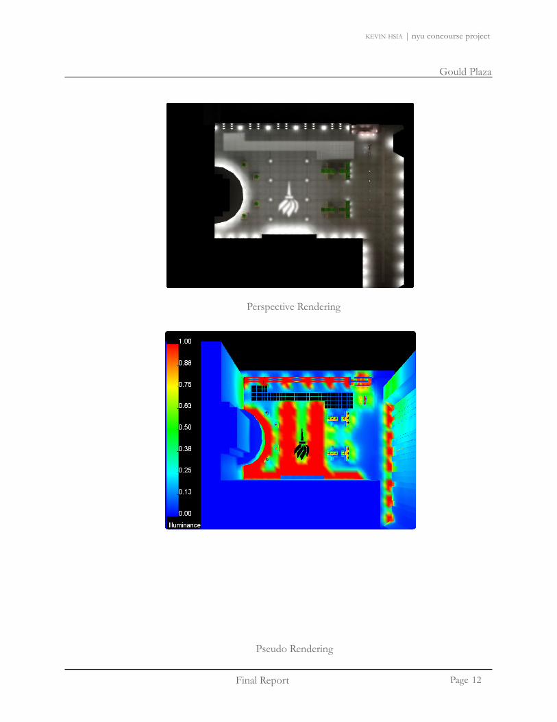
Perspective Rendering
Pseudo Rendering
12

Gould Plaza
Final Report
Gould Plaza
Page
kevin hsia | nyu concourse project
Pseudo Rendering
Pseudo Rendering
13

Final Report
Gould Plaza
Page
kevin hsia | nyu concourse project
Pseudo Rendering
14

Gould Plaza
Final Report
Gould Plaza
Page
kevin hsia | nyu concourse project
Perspective from corner
15
Perspective from front

Final Report
Gould Plaza
Page
kevin hsia | nyu concourse project
L9
L9
L9
L9
L9
L9
L10L10
0.3 0.9 3.8 1.4 6.2 1.3 0.4 0.2 0.1 0.1 0.1 0.1 0.1 0.2 0.6 2.4 11.2
0.5 1.5 6.5 9.8 3.0 0.8 0.3 0.2 0.1 0.1 0.1 0.2 0.2 0.4 1.1 4.1 16.3
.2 0.5 1.2 3.0 2.3 0.9 0.4 0.3 0.6 0.1 0.1 0.2 1.4 0.2 0.4 0.9 2.3
0.1 0.1 0.1 0.1 0.1 0.1 0.1 0.1 0.1 0.1 0.2 0.1
0.2 0.3 0.2 0.3 0.2 0.1 0.1 0.1 0.1 0.2 0.3 0.1
0.2 0.8 0.5 0.7 0.2 0.1 0.1 0.1 0.1 0.3 1.0 1.2
LL17 L17 L17 L17 L17
L14L14
5.8 6.7 7.9 7.8 7.2 6.9 7.4 7.0 6.8 6.7 7.4 7.5 7.3 7.6 8.3 7.3 6.3 5.2 0.0 3.3 3.8
5.8 6.7 7.4 7.3 7.1 6.9 6.7 6.5 6.8 6.7 6.8 7.0 7.4 7.6 8.0 7.4 6.5 5.1 4.0 2.9 1.5
4.5 5.4 5.5 5.5 5.6 5.3 4.8 4.8 5.2 5.2 5.0 5.2 6.0 6.0 6.1 5.9 5.4 4.1 2.8 1.9 1.1
3.1 3.8 4.1 4.0 3.7 3.3 3.2 3.1 3.0 3.1 3.2 3.5 3.7 4.2 4.3 4.4 3.8 2.8 2.0 1.3 0.7
2.2 2.9 3.1 2.9 2.4 1.9 1.5 1.3 1.3 1.4 1.4 1.6 2.0 2.6 3.1 3.3 3.1 2.3 1.5
2.0 2.8 3.0 2.7 2.1 1.4 0.9 0.7 0.7 0.7 0.7 1.0 1.4 2.1 2.8 3.1 2.8 2.1 1.3
1.9 2.6 2.9 2.6 1.9 1.2 0.8 0.6 0.5 0.5 0.6 0.8 1.2 1.9 2.6 2.9 2.7 2.0 1.3
1.6 2.2 2.4 2.2 1.6 1.1 0.7 0.5 0.5 0.7 1.1 1.6 2.1 2.4 2.2 1.7 1.1
1.3 1.7 1.8 1.7 1.3 0.9 0.7 0.5 0.9 1.3 1.7 1.8 1.7 1.3 1.0
Calculations
16

Gould Plaza
Final Report
Gould Plaza
Page
kevin hsia | nyu concourse project
L11 L11 L11
L1L11
L12 L12L12
L12
L12L12
L12
4.8
7.6
0.2
8.3
8.2
11.4
5.1
1.4
2.0
0.3 0.4 0.4 0.2 0.3 0.4 0.3
0.4 0.6 0.7 0.6 0.5
0.5 0.8 1.1 1.0 0.6
0.6 0.9 1.3 1.1 0.7
0.5 0.9 1.2 1.0 0.7
0.5 0.7 0.8 0.2 0.6 0.7 0.5
0.4 0.5 0.5 0.3 0.4 0.5 0.4
0.1 0.2 0.3 0.5 0.6 0.6 0.6 0.5 0.5 0.4
0.1 0.2 0.3 1.2 1.5 1.2 1.5 1.1 1.4 0.4
0.2 0.2
0.4 0.3 0.2 0.4 0.5 0.5 0.5 0.5 0.2 0.2
Calculations
17

Final Report
Gould Plaza
Page
kevin hsia | nyu concourse project
L14 L14
L14
L14
L14
L14
.4 2.2 2.9 3.1 2.9 2.4 1.9 1.5 1.3 1.3 1.4 1.4 1.6 2.0 2.6 3.1 3.3 3.1 2.3 1
.3 2.0 2.8 3.0 2.7 2.1 1.4 0.9 0.7 0.7 0.7 0.7 1.0 1.4 2.1 2.8 3.1 2.8 2.1 1
.2 1.9 2.6 2.9 2.6 1.9 1.2 0.8 0.6 0.5 0.5 0.6 0.8 1.2 1.9 2.6 2.9 2.7 2.0 1
.1 1.6 2.2 2.4 2.2 1.6 1.1 0.7 0.5 0.5 0.7 1.1 1.6 2.1 2.4 2.2 1.7 1
.0 1.3 1.7 1.8 1.7 1.3 0.9 0.7 0.5 0.9 1.3 1.7 1.8 1.7 1.3 1
.9 1.2 1.5 1.6 1.5 1.2 0.9 1.2 1.5 1.6 1.5 1.2 0
.0 1.4 1.8 1.9 1.7 1.3 1.3 1.7 1.9 1.8 1.4 1
.2 1.7 2.3 2.5 2.2 1.7 1.1 1.6 2.2 2.5 2.3 1.7 1
.3 2.0 2.7 2.9 2.6 1.9 1.2 0.8 1.2 1.9 2.6 2.9 2.7 2.0 1
.2 1.9 2.6 2.9 2.6 1.9 1.2 0.8 0.8 1.2 1.8 2.5 2.8 2.6 1.9 1
.1 1.6 2.1 2.3 2.1 1.6 1.1 0.7 0.7 1.0 1.5 2.1 2.3 2.1 1.6 1
.9 1.3 1.6 1.7 1.6 1.3 0.9 0.7 0.5 0.5 0.6 0.9 1.2 1.6 1.7 1.6 1.3 0
.9 1.2 1.4 1.5 1.4 1.1 0.9 0.6 0.5 0.5 0.6 0.8 1.1 1.4 1.5 1.4 1.2 0
.0 1.3 1.7 1.8 1.7 1.3 0.9 0.7 0.5 0.5 0.6 0.9 1.3 1.6 1.8 1.7 1.3 1
.1 1.7 2.2 2.4 2.2 1.6 1.1 0.7 0.5 0.5 0.7 1.1 1.6 2.1 2.4 2.2 1.7 1
.3 1.9 2.6 2.9 2.6 1.9 1.2 0.8 0.5 0.5 0.7 1.2 1.8 2.6 2.9 2.6 1.9 1
.3 1.9 2.6 2.9 2.6 1.9 1.2 0.8 0.5 0.4 0.4 0.5 0.7 1.2 1.8 2.6 2.9 2.6 1.9 1
.1 1.7 2.2 2.4 2.2 1.6 1.1 0.7 0.5 0.4 0.4 0.5 0.7 1.0 1.6 2.1 2.4 2.2 1.7 1
Calculations
18

Gould Plaza
Final Report
Gould Plaza
Page
kevin hsia | nyu concourse project
L17
L17
L17
L17
L17
L17
L17
L15
L15
L154.7 3.3 2.2
4.9 3.3 0.3
4.5 0.5
4.5 2.8 1.6 0.8 0.5
4.7 3.6 1.9 1.0 0.4
4.4 2.3 1.2 0.4
4.6 2.8 1.4 0.5
5.1 3.1 1.7 0.7
5.5 3.2 1.7 0.8
5.0 3.2 1.6 0.8
5.3 3.0 1.6 0.8
4.5 2.8 1.4 0.7
4.0 2.4 1.1 0.5
5.3 3.4 1.8 0.9 0.5
4.6 2.6 1.5 0.6 0.3
5.0 3.4 1.9 1.1 0.5
5.4 3.6 2.4 1.4 0.6 0.4
5.4 4.1 2.6 1.6 0.8 0.4
Calculations
19

Final Report
Gould Plaza
Page
kevin hsia | nyu concourse project
1.9 1.1 0.5 0.2 0.1
4.4 2.4 0.8 0.3 0.1
4.9 2.6 0.9 0.3 0.1
2.7 1.7 0.7 0.3 0.1
2.4 1.6 0.7 0.3 0.1
4.6 2.5 0.9 0.3 0.1
4.9 2.7 0.9 0.3 0.1
2.8 1.7 0.8 0.3 0.1
2.3 1.5 0.7 0.3 0.1
4.4 2.4 0.9 0.3 0.1
5.0 2.8 1.0 0.3 0.1
3.2 1.9 0.8 0.3 0.1
3.0 1.8 0.8 0.3 0.1
5.0 2.7 0.9 0.3 0.1
4.5 2.4 0.8 0.3 0.1
1.9 1.2 0.5 0.2 0.1
0 8 2 2 4 5
0.8 2.1 4.5
0.5 1.2 2.1
0.3 0.5 0.7
0.2 0.3 0.4
0.2 0.4 0.5
0.4 0.8 1.3
0.7 1.7 3.5
0.8 2.3 4.8
0.6 1.5 2.9
0.4 0.7 1.0
0.2 0.4 0.5
0.3 0.6 0.8
0.5 1.2 2.3
0.8 2.2 4.7
0.7 2.0 4.4
0.5 1.1 1.8
0.3 0.5 0.6
Calculations
20

Gould Plaza
Final Report
Gould Plaza
Page
kevin hsia | nyu concourse project
Label Calculation Type Units Avg Max Min Avg/Min Max/
MinArtwork Illuminance Fc 5.44 11.40 0.20 27.20 39.33
stairs step 5 Illuminance Fc 1.19 11.20 0.00 NA NAstairs step 3 Illuminance Fc 1.83 16.30 0.10 18.30 NAstairs step 1 Illuminance Fc 1.39 19.20 0.00 NA NA
Weaver Hall Entrance Illuminance Fc 1.40 4.50 0.20 7.00 22.50Tisch Hall entrance Illuminance Fc 1.74 8.30 0.00 NA NA
backpath (between Tisch & Weaver) Illuminance Fc 1.18 3.30 0.30 4.90 NA
Plaza Center Illuminance Fc 1.47 3.30 0.30 4.90 11.00
Calculation Summary: Gould Plaza
Gould Plaza Design Summary
The lighting design of Gould focuses on providing adequate light levels for safety to walk at night. The design philosophy is to reinforce the light levels at the main pathways and entrances. A custom lighted NYU logo is also created at the heart of the plaza to reinforce the NYU school spirit. The lighting design consists of metal halide downlights mounted on the outer walls of Tisch and Weaver Hall. A number of light poles are also proposed at the heart of the plaza to provide illumination for the benches and the walkway to west 4th street. At the steps on the north side of the plaza, step lights and light rails are proposed. Next to the stair steps recessed wall luminaires are used to light the ramp. At the center of the plaza, outdoor bench areas are proposed with landscape lighting.
The lighting provides a guide to help direct people at night. The average illumination in the plaza meets the recommended 1 fc. Even at areas with light levels lower than 1fc, the illumination levels meets the 0.5fc suggestion for outdoor parking - enhance security.
The boundaries of the plaza are lit so that people can see where they will walk to. The lighting also creates an interesting walking experience with the proposed NYU logo and lit art piece at the corner of the plaza. The lighting design consumes 4580W, well below the 5472 W limitation.
21

Final Report
Tisch Lobby
Page
kevin hsia | nyu concourse project
Tisch Hall, between West 4th and West 3rd St
Tisch Hall Lobby, ground level
lounge area
entrance/exit
entrance/exit
receptionsecurity
elevator waiting area
stairs leading toconcourses
Tisch Hall is located at the south center of Gould Plaza. Situated between Kaufman Management Center and Warren Weaver, the building hosts a number of classrooms for the New York Univer-sity’s Stern School of Business.
There are two entrances (revolving doors) that lead into Tisch Hall. The atrium space has a glass bridge that sits close to the curtain wall. There are two sets of stairs that lead to the bottom levels (upper and lower concourses) of Tisch Hall. In the lobby there are three elevator doors, sofa, reception desk, and hallways that connect to the other buildings. The new design will help introduce daylight into the space.
Tisch Hall Background Information
22

Tisch Lobby
Final Report
Tisch Lobby
Page
kevin hsia | nyu concourse project
lounge area
elevator waiting area
stairs leading toconcourses
Tisch Lobby (in red)
Type Description Finish Reflectance (assumed)
Wall
ST-2 Batek Diamante Limestone (smooth) Grey 0.5
WD-2 Bamboo Patina panel Light Brown 0.3P-1 White finish Eggshell 0.9
Wall Base FinishST-2 Batek Diamante Limestone Grey 0.5
CT-5B Gateway Ceramic Flooring Sterling Grey 0.3FlooringCT-5A Gateway Ceramic Flooring Sterling Grey 0.3Ceiling
ST-2 Batek Diamante Limestone GreyACT-5 Bamboo Patina panel Light Brown 0.9
P-1 White finish Eggshell 0.9
Finishes for Tisch Lobby
Materials for Tisch Lobby
23
Final Report
Tisch Lobby
Page
kevin hsia | nyu concourse project
Considerations and Criteria
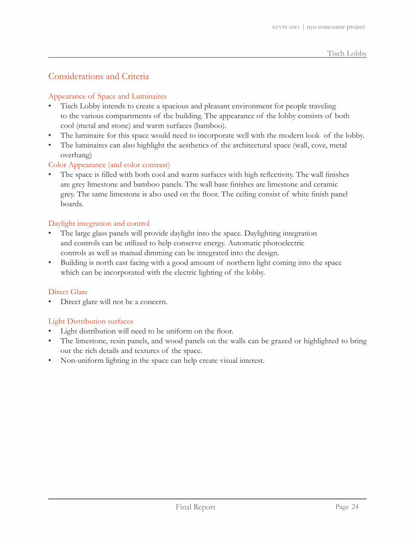
Appearance of Space and LuminairesTisch Lobby intends to create a spacious and pleasant environment for people traveling • to the various compartments of the building. The appearance of the lobby consists of both cool (metal and stone) and warm surfaces (bamboo). The luminaire for this space would need to incorporate well with the modern look of the lobby. • The luminaires can also highlight the aesthetics of the architectural space (wall, cove, metal • overhang)
Color Appearance (and color contrast)The space is filled with both cool and warm surfaces with high reflectivity. The wall finishes • are grey limestone and bamboo panels. The wall base finishes are limestone and ceramic grey. The same limestone is also used on the floor. The ceiling consist of white finish panel boards.
Daylight integration and controlThe large glass panels will provide daylight into the space. Daylighting integration • and controls can be utilized to help conserve energy. Automatic photoelectric controls as well as manual dimming can be integrated into the design. Building is north east facing with a good amount of northern light coming into the space • which can be incorporated with the electric lighting of the lobby.
Direct GlareDirect glare will not be a concern. •
Light Distribution surfacesLight distribution will need to be uniform on the floor. • The limestone, resin panels, and wood panels on the walls can be grazed or highlighted to bring • out the rich details and textures of the space. Non-uniform lighting in the space can help create visual interest. •
24

Tisch Lobby
Final Report
Tisch Lobby
Page
kevin hsia | nyu concourse project
Considerations and Criteria
Light distribution on Task Plane (Uniformity)The lighting distribution on the floor will be crucial for people to see where they walk. In general, • the lighting level in the lobby will need to be bright enough for security purposes to see the people entering/leaving the building.
Luminance of Room SurfacesSince the lobby is a converging point of various spaces, the lighting will need to address the paths • to the other compartments of the building. The focus should be lighting the elevator waiting area, stairs leading down into the upper and lower concourses, and the path leading to the Tisch hall-ways. The lighting brightness level can help define various traffic pattern.
Modeling of Faces and ObjectsModeling of faces will be crucial in this space. Security guards will need to see the people • entering/leaving the building. The stairs will also need to be bright enough for people to not fall. An important object to be lit is the security desk. The architectural glass bridge at the front of the entrance can also be lighted to showcase the modern aspect of the space.
Points of InterestPoints of interest to be lighted are the security desk, elevator waiting area, paths leading to other • compartments of the building (stairs leading down to the upper and lower concourses of the building), paintings, and Stern School of Business logo.
Reflected GlareThe reflected glare will be a concern for the atrium glass and the glass around the stairs. •
ShadowsShadows will not be a big concern in this space. •
25

Final Report
Tisch Lobby
Page
kevin hsia | nyu concourse project
Considerations and Criteria
Source/Task/Eye GeometryLight sources can also be positioned in a creative way to help lead people into various spaces in • the building.
Sparkle/Desirable Reflected HighlightsNot an issue. •
Surfaces CharacteristicsStainless steel doors, painted doors, glass doors, and fire rated wood doors.• Walls are smooth limestone, resin panels, wood panels, and painted gypsum wall board.• The floor is concrete with a high gloss.• The curtain wall is glass fin wall system with glass wall insulated glazing unit. • The revolving doors are glass.• The stairs are steel. •
System Control and FlexibilityThe lighting system will always be on for security issues. The lighting system • should be grouped into various regions. During nighttime, when there are not many people in the building, lighting in certain areas of the lobby can be dimmed or turned off.
Special ConsiderationsDaylight integration system with designed lighting system. •
Illuminance (Horizontal)10 fc –(IESNA Handbook: hotel lobby general lighting ) on floor• 30 fc on security desk –(IESNA Handbook: Reading Handwriting tasks- #2 pencil and • softer leads)
Illuminance (Vertical)
10 fc –(IESNA Handbook: hotel lobby general lighting ) on walls•
Energy 1.3 W/sq ft, additional 1.0 W/sq ft for decorative lighting (IESNA Standard 90.1-2007: Lobby) •
26

Tisch Lobby
Final Report
Tisch Lobby
Page
kevin hsia | nyu concourse project
The light design consist a mixture of downlights, recessed fluorescants, LED cove system, and pendants. The main issue is to solve the traffic congestion in the lobby. Proposed ‘light guides’ (recessed linear fluorescents, lighted glass box, and custom pendants) will be used to solve this problem.
Security Desk At the security desk, suspended decorative pendants provides illumination and visual interest. The use of the pendants also helps bring down the scale of the lobby to the security desk (in large spaces, occupants can often feel out of place due to the high ceiling height).
Elevator Waiting Area Above the elevator waiting area, recessed LEDs are used to light the school logo. General illumination at the elevator waiting area will be provided by the downlights and recessed ‘light guides’ on the sides of the elevator doors.
Stairs to Upper and Lower ConcourseThe decorative custom pendant and downlights will provide illumination to the stairs.
Hallways and Doors to StairsA combination of linear recessed fluorescants and glass boxes will be used as ‘light guides’.
Tisch Hall Lighting Design
27

Final Report
Tisch Lobby
Page
kevin hsia | nyu concourse project
Custom Luminaire
The custom luminaire consist of curved metal rings with support metal pieces on the inner corners of the luminaire. A number of thin metal rods are placed at vari-ous levels of the luminaire to help support the acrylic blocks. A 24W T5 linear strip is inserted at the center of the luminaire, with a plastic housing over it.
The meaning behind this luminaire symbolizes the buildings blocks of knowledge. The mixture of all the knowledge is funneled. The funneling represents education being provided to the students.
28

Tisch Lobby
Final Report
Tisch Lobby
Page
kevin hsia | nyu concourse project
Lighting Floor Plan
Reflected Ceiling Plan
*Larger lighting plan can be found in Appendix I : L201, L202
29

Final Report
Tisch Lobby
Page
kevin hsia | nyu concourse project
ImageType Manufacture Fixture
Description Watt Quantity Lamp Ballast Model
L4 Selux M60
Recessed linear fluorescent 39 14 FP28/835/ECO Osram
Sylvania Lutron Eco-10 M6R1-1T5-MA-PM-004-SV-277
L5A Kurt Versen H8632
Recessed compact
fluorescent downlight
36 34 CF32DT/E/IN/835/ECO Osram Sylvania
Advance IDL-2S26-M5-
BSH8632
L5B Kurt Versen H8653
Recessed compact
fluorescent wallwasher
36 4 CF32DT/E/IN/835/ECO Osram Sylvania
Advance IDL-2S26-M5-
BSH8653
CUSTOM L6 Custom Decorative 27 3 FP24/835/HO/ECO Advance ICN- C st m
Lighting Fixture Schedule for Tisch Lobby
CUSTOM L6 Luminaire Pendant 27 3 / / /Osram Sylvania 2S24@120V Custom
L7
Electrix Adjustsable
Linear Fluorescent
Linear Cove System 39 39 FP28/835/ECO Osram
Sylvania Lutron Eco-10 AX-28-S1-U-D3-156
L8 Schmitz Public
Surface compact fluorescent
sconce46 4 CF42DT/E/IN/835/ECO
Osram Sylvania
Advance ICF-2S26-H1-
LD@120 16991.06/2830
L19Color Kinetics
eW Cove Powercore
Linear cove System 4.5 19 LED Driver 523-000004-00-
910403600103
Type Mainenance Category
Dirt Conditions
Cleaning Period LDD Initial Lumens Mean
Lumens LLD BF Total LLF
L4 IV Clean 12 months 0.88 2900 2697 0.93 1 0.82L5A IV Clean 12 months 0.88 2400 2064 0.86 1 0.76L5B IV Clean 12 months 0.88 2400 2064 0.86 1 0.76L6 I Clean 12 months 0.94 1750 1627 0.93 1.02 0.89L7 VI Clean 12 months 0.86 2900 2697 0.93 1 0.80L8 IV Clean 12 months 0.88 3200 2752 0.86 0.98 0.74L19 VI Clean 12 months 0.86 135 - - 1 0.86
Light Loss Factor for Tisch Hall
30

Tisch Lobby
Final Report
Tisch Lobby
Page
kevin hsia | nyu concourse project
Type Manufacture Watt Quantity Watt Energy AllowedL4 Selux M60 39 14 546
L5A Kurt Versen H8632 36 34 1224
L5B Kurt Versen H8653 36 4 144
L6 Custom Luminaire 27 3 -
L7Electrix
Adjustsable Linear Fluorescent
39 39 1521
L8 Schmitz Public 46 4 184
L19Color Kinetics
eW Cove Powercore
4.5 19 85.5
3704.5 4595.51.05 1.3
Energy Calculation for Tisch Hall
Consumed PowerPower Density
Red - DesignedBlue - IESNA recommended
Energy
The lighting power density analysis was performed with the space by space method recommended by ASHRAE Standard 90.1-2007. The energy code limits the plaza to 1.3 W/sq.ft. The total energy consumed in the plaza is about 3705W, well below the 4596 W limitation.
Tisch Lobby Control
All luminaires will be connected to the Lutron Grafik Eye 3000 System. The Grafik Eye system will use a daylighting sensor to dim the lightings according to the daylight condition in the space.
Image Manufacture Prdouct Description Model
Control Schedule for Tisch Lobby
Image Manufacture Prdouct Description Model
GRAFIK Eye 3000 Series
Automatic Preset scenes in response to ambient
daylight.GRX-DACPI-MW-PS-WH
31

Final Report
Tisch Lobby
Page
kevin hsia | nyu concourse project
Perspective Rendering at security gate
Pseudo Rendering
32

Tisch Lobby
Final Report
Tisch Lobby
Page
kevin hsia | nyu concourse project
Perspective Rendering at front
Pseudo Rendering
33

Final Report
Tisch Lobby
Page
kevin hsia | nyu concourse project
Perspective Rendering
Elevator Lobby
34

Tisch Lobby
Final Report
Tisch Lobby
Page
kevin hsia | nyu concourse project
7.1 9.3 10.5 11.2 11.7 12.1 12.4 12.9 13.2 13.5 13.4 13.1 12.3
10.3 13.0 13.4 14.0 14.7 15.1 15.5 16.0 16.2 16.5 16.1 15.8 17.1
14.9 16.2 16.1 16.7 17.5 17.8 18.2 18.4 18.4 18.1 18.2 17.8 17.6
12.8 16.1 17.5 18.5 19.8 20.2 20.7 20.0 19.3 19.1 18.9 18.6 18.2
13.0 16.6 18.6 20.4 21.0 22.4 21.6 21.2 21.1 20.3 20.1 19.3 18.3
15.4 16.7 20.7 20.3 20.1 19.6 18.9
12.2 14.4 20.0 19.9 20.0 19.6 19.4
9.2 12.0 13.9 13.0 16.1 13.6 16.2 16.2 16.9 16.6 15.8
7.3 9.3 11.0 12.5 13.4 13.7 11.8 7.6 10.3 10.1 9.3
16.9 14.7 13.9 13.1 11.5
17.4 16.9 14.2 13.0 11.9
12.1 11.8 8.2 9.5 9.0
2.1 2.2 2.4 2.8 3.1 3.2 3.2 3.6 3.6 3.8 3.71.8 1.9 2.3 3.3 3.7 3.8 3.5 3.9 3.9 4.5 4.21.8 1.8 2.3 3.4 3.8 3.9 3.5 3.9 3.9 4.6 4.72.0 2.1 2.7 3.6 4.0 4.1 4.3 4.8 4.8 5.4 5.62.1 2.1 2.8 3.5 3.9 4.1 4.5 5.0 5.0 5.7 5.72.1 2.1 2.8 3.5 3.9 4.1 4.5 5.0 5.0 5.7 5.72.0 2.1 2.7 3.1 3.5 3.7 3.9 4.2 4.3 4.5 3.4
9.49.39.29.19.19.29.29.2 8.68.68.58.58.48.58.58.5
11.712.312.613.514.616.5 0.18.29.80.18.513.6
29.5 30.6 31.6 32.9 34.2 35.6 36.2 36.0 35.9 35.6 35.1 34.7
24.4 26.2 27.6 29.7 31.4 31.5 31.7 32.9 33.9 33.5 32.9 32.9 32.2
22.4 24.3 25.7 26.2 27.9 28.8 29.5 30.1 30.8 31.5 32.2 32.5 31.7
30.7 29.6
28.6 26.5
26.8 26.5
24.2 24.7
21.2 21.7
18.6 18.9
35

Final Report
Tisch Lobby
Page
kevin hsia | nyu concourse project
8.0
8.4
9.0
9.8
10.5
10.3
9.0
7.8
8.2
8.7
9.2
9.4
9.1
8.3
7.7
8.2
8.6
8.8
8.8
8.6
8.2
7.5
7.9
8.3
8.5
8.5
8.3
8.0
7.3
7.7
8.1
8.2
8.2
8.1
7.8
13.5 13.4 13.1 12.3 14.3 12.3 11.6 10.2 10.5 11.1 12.1 13.8 13.7 11.9 12.5 12
16.5 16.1 15.8 17.1 16.6 15.3 14.7 14.4 13.0 14.3 15.4 16.6 17.0 14.7 15.2 15
18.1 18.2 17.8 17.6 17.2 14.9 15.8 14.9 15.0 16.0 14.7 15.9 18.0 17.5 16.8 1
19.1 18.9 18.6 18.2 14.8 14.4 12.9 14.2 14.0 13.1 14.4 14.4 18.1 18.3 17.7 1
20.3 20.1 19.3 18.3 15.8 18.1 18.1 1
20.3 20.1 19.6 18.9 18.2 18.5 18.4 1
19.9 20.0 19.6 19.4 18.0 18.3 18.3 1
16.2 16.9 16.6 15.8 14.0 15.5 15.2 13
7.6 10.3 10.1 9.3 8.6 9.1 9.2 4
14.7 13.9 13.1 11.5 10.2 11.4 11.1 9
16.9 14.2 13.0 11.9 10.4 10.8 10.6 9
11.8 8.2 9.5 9.0 7.6 8.2 6.5 5
9.0 8.2 7.8 8.0 7.8 7.9 7.6 7.4 7.7 7.9 8.6
9.8 8.8 8.5 8.2 8.5 8.2 8.2 8.1 8.5 8.8 9.1
8.9 11.7 9.6 9.4 9.6
13.8 15.3 14.1 14.2 13.1
13.1 13.9 15.2 14.1 12.1
7.8 7.9 7.9 7.9 7.9 7.9 7.9 7.9
0.0 0.0 0.0 0.0 0.0 0.0 0.0 0.0
9.2
12.2
13.9
13.3
11.9
8.6
10.9
13.1
12.7
10.8
11.712.312.613.5 0.18.29.80.1
7.37.06.76.76.96.57.87.56.77.3 7.97.67.27.27.37.07.27.27.48.0
26.232.636.232.630.529.530.932.235.334.332.333.631.334.435.034.834.030.627.47.5
36

Tisch Lobby
Final Report
Tisch Lobby
Page
kevin hsia | nyu concourse project
8.0
8.4
9.0
9.8
10.5
10.3
9.0
7.8
8.2
8.7
9.2
9.4
9.1
8.3
7.7
8.2
8.6
8.8
8.8
8.6
8.2
7.5
7.9
8.3
8.5
8.5
8.3
8.0
7.3
7.7
8.1
8.2
8.2
8.1
7.8
13.7 11.9 12.5 12.3 12.1 11.3 10.8 10.3 9.9 9.6 9.1 8.2 6.2
6 17.0 14.7 15.2 15.1 14.8 13.9 13.3 12.7 12.2 11.8 11.5 11.3 9.6
18.0 17.5 16.8 16.8 16.1 15.9 15.1 14.5 14.1 13.8 13.6 13.9 13.9
18.1 18.3 17.7 17.5 16.9 16.9 16.3 15.8 15.3 14.8 14.3 13.7 11.3
15.8 18.1 18.1 18.2 17.5 17.1 16.7 16.2 15.7 15.2 14.6 13.8 11.3
18.2 18.5 18.4 18.2 17.6 16.9 16.4 15.9 15.3 14.7 14.3 14.6 14.2
18.0 18.3 18.3 17.4 16.9 16.1 15.3 14.7 14.1 13.4 12.9 12.6 10.8
14.0 15.5 15.2 13.3 12.7 14.2 13.6 13.0 12.3 11.5 10.7 9.6 7.5
8.6 9.1 9.2 4.9 6.9 11.7 11.1 10.6 10.1 9.4 8.6 7.4 5.8
10.2 11.4 11.1 9.6 9.2
10.4 10.8 10.6 9.7 7.6
7.6 8.2 6.5 5.9 5.8
37

Final Report
Tisch Lobby
Page
kevin hsia | nyu concourse project
Label Calculation Type Units Avg Max Min Avg/Min Max/
MinLobby ground floor Illuminance Fc 14.67 22.4 4.9 2.99 4.57
Entrance Illuminance Fc 10.96 17.4 5.8 1.89 3Security Desk Illuminance Fc 28.22 33.9 18.6 1.52 1.82NYU Logo Illuminance Fc 31.06 36.2 7.5 4.14 4.83Glass Bridge Illuminance Fc 8.3 9.8 7.4 1.12 1.32
Stairs platform Illuminance Fc 12.54 15.3 8.9 1.41 1.72Stairs platform 1 Illuminance Fc 12.1 13.9 9.2 1.32 1.51Stairs platform2 Illuminance Fc 11.22 13.1 8.6 1.3 1.52
Calculation Summary: Tisch Hall
Tisch Hall Design Summary
The lighting of design Tisch Lobby strives to simplify the traffic congestion in Tisch Hall. Tisch Lobby is connected to the various compartments in the building (two hallways, stairs to the lower concourses, elevator lobby, four sets of stairway, and the entrance/exit). The design solution uses light to create guides in which people can be directed to their destination. The lighting guides consist of wall recessed linear fluorescents, custom pendants, and lighting glass blocks. The average illuminance level on the floor is 15 fc, over the recommended 10 fc. With a brighter floor, the physiological feel of the space will be perceived to be larger, cleaner, and safer. For the hallways and elevator lobby, recessed linear fluorescents are mounted on the sides of the entrance to help guide the occupants. As for the four sets of stairs, above each stairway a glass block is backlit. The glass block consists of student faces mounted on the frosted glass that can create a point of visual interest. In terms of the stairs leading down to the lower concourse, custom pendants are created to make occupants aware of the space below. The rest of the lighting design enhances the overall architecture of the space. The pendants over the security desk are suspended to help bring the physiological feel of the large space down. Fluorescent wallwashers and downlights are used to provide uniform illumination in the space.
The lighting design meets the design criteria. For the illuminance level of the ground floor, there is an average illuminance value of 14.67 fc, which meets the 15 fc design criteria (IESNA suggests 10 fc). The stairs area are also able to provide between 11-12 fc, again over the 10 fc requirement. Over-all, the lighting design meets the ASHRAE/IESNA Standard 90.1. The lighting design consumes 3705 watts which is below the maximum of 4596 watts.
38

Tisch Lobby
Final Report
General Classroom
Page
kevin hsia | nyu concourse project
Classroom Background Information
One of the objectives of the NYU Concourse Project is to connect the three existing buildings. In the concourse project, new classrooms are constructed for the Stern School of Business. The classroom sizes range from a capacity of 20-73 occupants.
The classroom (U18) is rectangular. The seating arrangement is semi circular with a total of 73 seats. There are three white boards at the front, with the center white board having a vertical sliding component that can be adjusted into a projection surface. The projection screen at the front is attached to the ceiling of the classroom. The seating arrangement is divided into various elevation heights.
projection screens and white boards
entrance/exit
closet
clothes rack
lecture tables/desk
Classroom Plan
39

Final Report
General Classroom
Page
kevin hsia | nyu concourse project
Materials for Tisch Lobby
Type Description Finish Reflectance (assumed)
WallP-5 Eggshell Finish Concord Ivory 0.6P-6 Eggshell Finish Swiss Coffee 0.6
Wall Base FinishRB-5 Rubber Thermoplastic Bright Orange 0.5RB-6 Rubber Thermoplastic Bright Orange 0.5FloorCPT-3 Broadloom carpet Navy Blue (assumed) 0.3CeilingACT-2 Ceiling Material White 0.9
FurnitureChalkboard White Plastic 0.6
Chairs Red Leather 0.5
Finishes for Classroom
Classroom West Elevation
40

Final Report
General Classroom
Page
kevin hsia | nyu concourse project
Considerations and Criteria
Appearance of Space and LuminairesThe typical classroom is intended to create a comfortable learning environment in • which students can enhance their learning experience. The focus point is the three white boards and projection surface at the front of the classroom. Lighting levels on the vertical surface would need to be bright enough for people to read. The desks will be arranged in a semi-circular format which can help contribute to the newly • designed luminaires to be arranged in a playful manner with the orientation of the desks. The space needs to introduce an impression of visual clarity and pleasantness to provide students • with the best learning environment. The projector located on the surface of the ceiling would be an obstacle for any suspended • luminaires (block projector view).
Color Appearance (and color contrast)The color surfaces of the classroom are bright. The wall finishes are ivory and light • coffee toned with a white ceiling panel boards with a navy blue carpet. The lighting from the luminaires needs to accompany the cool tones of the classroom • to make the space feel clean and efficient. In a brighter and cool toned environment, work efficiency is higher in comparison to a relaxed warm tone environment. The cool tone will also help enhance the reading visibility of the white boards at the front of the room.
Daylight integration and controlDaylight integration will not be a concern since there are no windows.•
Light Distribution surfacesLight distribution on the tables will need to be uniform to provide an pleasant learning environ-• ment for every student in the classroom. The light distribution on the three white boards at the front of the room will need to be uniform so that the visibility conditions will be the same.
41

Final Report
General Classroom
Page
kevin hsia | nyu concourse project
Considerations and Criteria
Light Distribution on Task Plane (Uniformity)The lighting distribution at the desk plane (2.5 feet for table height) will need to provide enough • light for writing and reading. Since the floor will not all be on the same plane (various seating heights), the light level on the floor • would need to be maintained as uniform as possible.
Luminances of Room SurfacesThe front of the classroom (whiteboard and podium) should have higher luminance • levels in the space followed by the desks (student sitting area). The back and side of the space will have lower light levels on the walls. The floor should have the least amount of light level in comparison with the rest of the surfaces.
Modeling of Faces and ObjectsA healthy learning environment would provide sufficient light levels for the professor and • students to communicate. Facial recognition will be a critical concern for the professor at the front of the room and the students sitting. The three white boards in the front of the board also need to have enough brightness for • reading.
Points of InterestPoints of interest to be lighted: Three white boards and podium at the • front of the room.
Reflected GlareThe reflected glare on the projection screen will be a concern for students looking. It would be • hard to read if the board is too bright This can be prevented by using luminaires with a narrow beam angle or adjustable luminaire to prevent light from spilling onto the projection screen.
42

Final Report
General Classroom
Page
kevin hsia | nyu concourse project
Considerations and Criteria
ShadowsSufficient light levels should be provided so that shadows do not interfere with writing and reading • visibility (desk and white boards at front of room).
Source/Task/Eye GeometryLight sources need to be positioned right above the table height for writing, reading, • facial rendering purposes. Light source will also need to be positioned correctly to provide enough light levels on the white • boards.
Surfaces CharacteristicsVertical sliding white boards with rear projection screen. • Painted gypsum wall board. • Resin panels. • Wood credenza with locker cabinets, resin counter top, and adjustable shelves.• Doors are coated metal. •
System Control and FlexibilitySince the classroom would have a variety of different learning conditions (lecture, presentation • with projector screen), the classroom must have a flexible lighting control tailored towards the different activities.
[Lecture mode] – light levels can be adjusted to have a better writing/reading. [Presentation mode] - lighting levels will need to dim
Illuminance (Horizontal)• [Study Mode] 30 fc –(IESNA Handbook: Reading Handwriting tasks- #2 pencil and softer leads) Illuminance (Vertical)• [Presentation Mode] Less than 5 fc on front screen project systems – (IESNA DG17-05)
Energy • 1.4 W/sq ft – (IESNA Standard 90.1-2007: Classroom/lecture/training) 1.0 W/sq ft for accent
43

Final Report
General Classroom
Page
kevin hsia | nyu concourse project
Design Objective
Going along with the overall lighting design concept of the New York University Concourse Project, the lighting system for the classroom will strive to enhance the learning experience of students at New York University. Lighting will be addressed on the surfaces that are the most important in the space. In the case for the classroom, the important surfaces are the white boards at the front of the room and the student desks.
Lighting Design
The lighting design consist a mixture of downlights, wallwashers, and recessed linear fluorescents. The downlights are used to provide general ambient lighting and specifically, sufficient light levels on the student desks. For the wallwashers at the front of the classroom, they are used to light up the white board/projection screen. The cove lighting on the sides of the room help graze the wall to make the classroom feel spacious.
44

Final Report
General Classroom
Page
kevin hsia | nyu concourse project
Lighting Reflected Ceiling Plan
*Larger lighting plan can be found in Appendix : L301
45

Final Report
General Classroom
Page
kevin hsia | nyu concourse project
ImageType Manufacture Fixture
Description Watt Quantity Lamp Ballast Model
L1A Kurt Versen P921
Recessed compact
fluorescent wallwasher
36 27 CF32DT/E/IN/835/ECO Osram Sylvania
Advance IDL-2S26-M5-
BSP921
L2A Selux M100
Recessed linear fluorescent wall
washer39 7 FP28/835/ECO Osram
Sylvania
LUTRON ECO-T528-277-
1
M1A-1T5-AMP-PM-004-SV-277-X
L2BSelux M100
Recessed linear fluorescent wall 31 3 FP28/835/ECO Osram
S l ni
Advance ICN-2S28- M1B1S-1T5-SD-PM-
68 SV 277
Lighting Fixture Schedule for General Classroom
Super Recessed washer Sylvania N@120 68-SV-277
L3 Litecontrol Wall/Slot-2000
Recessed perimeter fixture 36 16 FP28/835/ECO Osram
Sylvania
LUTRON ECO-T528-277-
1#14716000
TypeMainena
nce Category
Dirt Conditio
ns
Cleaning Period LDD Initial
LumensMean
Lumens LLD BF Total LLF
L1 IV Clean 12 months 0.88 2400 2064 0.86 1 0.76L2 IV Clean 12 months 0.88 2900 2697 0.93 1 0.82
0.88 IV Clean 12 months 0.88 2900 2697 0.93 1 0.82L3 II Clean 12 months 0.88 2900 2697 0.93 1 0.82
Light Loss Factor for General Classroom
I M f t P d t D i ti M d l
Control Schedule for General Classroom
Image Manufacture Prdouct Description Model
GRAFIK Eye 3000 Series
Pushbutton to recall 2 preset lighting scenes GRX-3502-T-AU-WH
46

Final Report
General Classroom
Page
kevin hsia | nyu concourse project
Type Manufacture Watt Quantity Power Energy Allowed
L1A Kurt Versen P921 36 27 972 1390 sq. ft x 1.4 wt/sq. ft
L2A Selux M100 39 7 273
L2B Selux M100 Super Recessed 31 3 93
L3 Litecontrol Wall/Slot-2000 36 16 576
1914 19461.38 1.4
Energy Calculation for General Classroom
Consumed PowerPower Density
Red - DesignedBlue - IESNA recommended
Energy
The lighting power density analysis was performed with the space by space method recommended by ASHRAE Standard 90.1-2007. The energy code limits the plaza to 1.4 W/sq.ft. The total energy consumed in the plaza is about 1914W, right under the 1946 W limitation.
47

Final Report
General Classroom
Page
kevin hsia | nyu concourse project
reflected ceiling plan
plan not to scale
20% Dimming
50% Dimming
70% Dimming
reflected ceiling plan
No Dimming for anyof the luminaires in the space.
plan not to scale
Classroom Control Modes
The luminaires in the classroom will be connected to the Lutron Grafik Eye 3000 System. A total of two preset light modes will be used: general mode and presentation mode. During the presentation mode, the downlights will be divided into three different zones and dim accordingly. The main con-trol unit will be at the front of the classroom. Additional wall stations will be located at the entrance to the classroom.
General Mode
Presentation Mode
48
Final Report
General Classroom
Page
kevin hsia | nyu concourse project
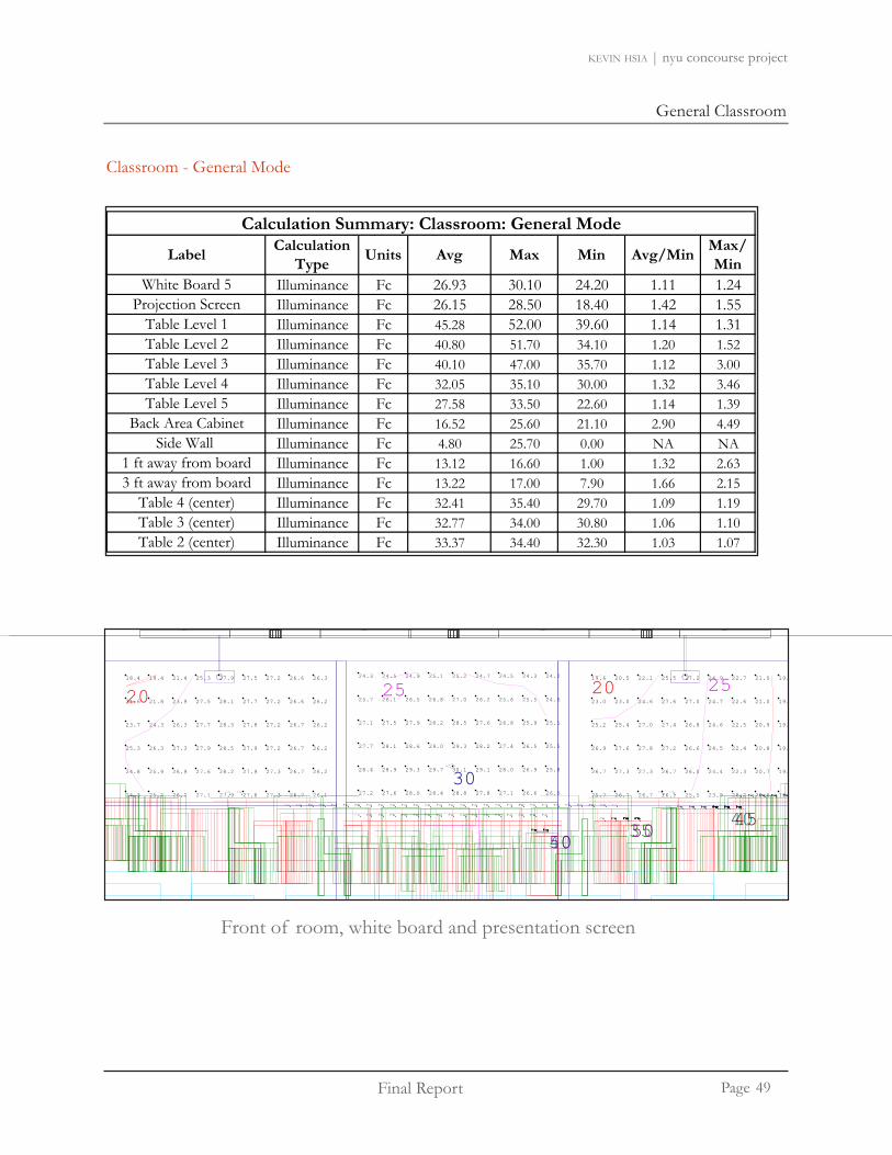
Label Calculation Type Units Avg Max Min Avg/Min Max/
MinWhite Board 5 Illuminance Fc 26.93 30.10 24.20 1.11 1.24
Projection Screen Illuminance Fc 26.15 28.50 18.40 1.42 1.55Table Level 1 Illuminance Fc 45.28 52.00 39.60 1.14 1.31Table Level 2 Illuminance Fc 40.80 51.70 34.10 1.20 1.52Table Level 3 Illuminance Fc 40.10 47.00 35.70 1.12 3.00Table Level 4 Illuminance Fc 32.05 35.10 30.00 1.32 3.46Table Level 5 Illuminance Fc 27.58 33.50 22.60 1.14 1.39
Back Area Cabinet Illuminance Fc 16.52 25.60 21.10 2.90 4.49Side Wall Illuminance Fc 4.80 25.70 0.00 NA NA
1 ft away from board Illuminance Fc 13.12 16.60 1.00 1.32 2.633 ft away from board Illuminance Fc 13.22 17.00 7.90 1.66 2.15
Table 4 (center) Illuminance Fc 32.41 35.40 29.70 1.09 1.19Table 3 (center) Illuminance Fc 32.77 34.00 30.80 1.06 1.10Table 2 (center) Illuminance Fc 33.37 34.40 32.30 1.03 1.07
Calculation Summary: Classroom: General Mode
Classroom - General Mode
33.5 34.2 35.2 35.4
33.6 33.7 33.7 33.8 34.0 34.0 33.9 33.9 33.6 33.9 33.4 33.7 33.5 33.1 33.4 33.0 33.2 33.0 33.2 33.1 33.6 33.6 33.9 33.9 33.8 33.7 33.5 33.4 33.2 33.1 33.1 33.1 32.9 32.9 32.5 32.6 32.1 32.2 31.6 31.4 31.4 31.1 30.8 31.3 30.9 31.5 31.0 31.9 31.4 31.9 31.5 32.2 32.0 32.3 32.1 32.2 32.3 32.2 32.5
34.3 34.2 34.1 34.3 34.1 34.4 34.2 34.3 33.9 34.4 34.0 34.3 33.8 34.0 33.5 33.6 33.2 33.5 33.0 33.4 32.9 33.2 32.7 33.0 32.6 32.8 32.5 32.5 32.3 32.3 32.4 32.3 32.3 32.4
27.2 27.6 28.0 28.4 28.8 27.8 27.1 26.6 26.0
28.4 28.9 29.3 29.7 30.1 29.1 28.0 26.9 25.8
27.7 28.1 28.6 29.0 29.3 28.2 27.4 26.5 25.5
27.1 27.5 27.9 28.2 28.5 27.6 26.8 25.9 25.1
25.7 26.1 26.5 26.8 27.0 26.2 25.6 25.5 24.6
24.3 24.5 24.9 25.1 25.2 24.7 24.5 24.3 24.2
25.7 26.7 26.7 26.1 25.5 23.9 22.2 20.6 19.7
26.7 27.3 27.3 26.7 26.0 24.4 22.3 20.7 19.5
26.9 27.6 27.8 27.2 26.6 24.5 22.4 20.8 19.6
25.2 25.4 27.0 27.4 26.8 24.6 22.5 20.9 19.7
23.0 23.0 24.6 27.6 27.0 24.7 22.6 21.0 19.7
19.6 20.5 22.1 25.5 27.2 24.9 22.7 21.0 19.5
51.9 50.5 49.1 47.7 46.3 45.1 43.9 42.8 41.7 40.7 39.8 51.5 50.2 48.9 47.4 46.0 44.9 43.7 42.5 41.4 40.5 39.6
34.7 34.2 38.5 37.5 36.4 35.4 34.6 34.2 34.1 51.7 50.1 48.5 46.9 45.4 44.2 43.4 42.6 41.9 41.1 40.2 39.4 38.5 37.5 36.4 35.4 34.5 34.1 50.9 49.5 47.9 46.4 45.0 44.0 43.1 42.3 41.5 40.8 39.9 39.1 38.2 37.3 36.2
36.0 36.3 36.3 36.2 36.0 36.0 36.2 36.1 36.2 36.1 35.8 37.1 36.8 36.4 36.2 36.1 35.9 35.7 47.0 46.8 46.5 45.9 45.5 44.9 44.2 43.4 42.5 41.6 40.7 40.0 39.3 38.8 38.5 38.1 38.0 37.8 37.5 37.2 36.8 36.4 36.0 45.4 45.4 45.4 45.2 44.9 44.5 43.9 43.2 42.4 41.5 40.7 39.9 39.2 38.7 38.5 38.4 38.2 38.1 37.9 37.5 36.9 44.3 44.3 44.4 44.5 44.1 43.7 43.3 42.6 41.6 41.2 40.6 39.8 39.1 38.7 38.5 38.5 38.1
37.6 37.2 37.4 37.8 37.8 37.6 37.4 37.5 37.7 37.9 37.8 37.4 38.4 38.4 38.2 38.0 37.8 39.8 39.7 39.6 39.3 38.8 39.6 39.6 40.1 40.5 40.7 40.7 40.5 39.9 41.5 42.5 43.3 43.9 44.2 44.0 43.4 42.9 42.8 42.5 42.4 42.9 43.3 43.2 43.0 42.7 42.4 41.7 40.8 40.3 40.3 40.1 40.2 40.8 41.2 41.2 41.0 41.0 42.0 42.8 43.6 44.0 43.9 43.4 43.1 42.9 42.8 42.8 43.1 43.6 43.4 43.1 42.9 42.8 42.2 41.3 40.8 40.7 40.5 40.7 41.2 40.5 41.5 42.4 43.2 43.7 43.7 43.4 43.1 43.1 42.9 42.9 43.3 43.6 43.5 43.3 43.1 42.9 42.3 41.6 41.124.3 25.2 26.2 27.1 27.9 27.6 27.3 26.7 26.1
24.8 25.9 26.9 27.6 28.2 27.9 27.3 26.7 26.2
25.3 26.3 27.3 27.9 28.5 27.9 27.2 26.7 26.2
23.7 24.3 26.3 27.7 28.3 27.8 27.2 26.7 26.2
21.6 21.8 23.9 27.5 28.1 27.7 27.2 26.6 26.2
18.4 19.4 21.4 25.3 27.9 27.5 27.2 26.6 26.3
25
30
20 25
40503550
404540
20
Front of room, white board and presentation screen
49

Final Report
General Classroom
Page
kevin hsia | nyu concourse project
Classroom - General Mode
51.9 50.5 49.1 47.7 46.3 45.1 43.9 42.8 41.7 40.7 39.8
51.5 50.2 48.9 47.4 46.0 44.9 43.7 42.5 41.4 40.5 39.6
34.7 34.2
38.5 37.5 36.4 35.4 34.6 34.2 34
51.7 50.1 48.5 46.9 45.4 44.2 43.4 42.6 41.9 41.1 40.2 39.4 38.5 37.5 36.4 35.4 34.5 34.1
50.9 49.5 47.9 46.4 45.0 44.0 43.1 42.3 41.5 40.8 39.9 39.1 38.2 37.3 36.2
4050
3550
Student desk, row 3 and 447.0 46.8 46.5 45.9 45.5 44.9 44.2 43.4 42.5 41.6 40.7 40.0 39.3 38.8 38.5 38.1 38.0
45.4 45.4 45.4 45.2 44.9 44.5 43.9 43.2 42.4 41.5 40.7 39.9 39.2 38.7 38.5 38.4 38.2
44.3 44.3 44.4 44.5 44.1 43.7 43.3 42.6 41.6 41.2 40.6 39.8 39.1 38.7 38.5 38.5 38.1
41.5 42.5 43.3 43.9 44.2 44.0 43.4 42.9 42.8 42.5 42.4 42.9 43.3 43.2 43.0 42.7 42.4 41.7 40.
41.0 42.0 42.8 43.6 44.0 43.9 43.4 43.1 42.9 42.8 42.8 43.1 43.6 43.4 43.1 42.9 42.8 42.2 41.
40.5 41.5 42.4 43.2 43.7 43.7 43.4 43.1 43.1 42.9 42.9 43.3 43.6 43.5 43.3 43.1 42.9 42.3 41.
4045
Student desk, row 1 and 2
50

Final Report
General Classroom
Page
kevin hsia | nyu concourse project
Classroom - General Mode
33.4 33.0
33.2 33.0
33.2 33.1
33.6 33.6
33.9 33.9
33.8 33.7
33.5 33.4
33.2 33.1
33.1 33.1
32.9 32.9
32.5 32.6
32.1 32.2
31.6 31.4
34.2 34.1
34.3 34.1
34.4 34.2
34.3 33.9
34.4 34.0
34.3 33.8
34.0 33.5
33.6 33.2
33.5 33.0
33.4 32.9
33.2 32.7
33.0 32.6
32.8 32.5
student desk, center row 2 and 3
51

Final Report
General Classroom
Page
kevin hsia | nyu concourse project
Classroom - General Mode
31.0 30.8
31.1 30.9
30.9 31.1
30.9 30.8
31.0 30.8
31.5 31.2
32.3 31.6
33.7 33.0 32.1
34.3 34.1 33.4
34.7 34.5 33.7
35.2 35.1 34.7
35.4 35.2
35.0
24.3 23.5 2
24.6 23.7 2
25.1 24.0 2
25.7 24.3
27.9 26.7 25.2
29.2 27.9 26.3
31.3 30.1 28.8
31.8 30.5 29.1
33.0 32.1 30.7
33.1 32.4 31.1
33.2 33.1 32.6
32.8 32.7 32.1
33.2 32.7 32.1
33.5 32.8 32.1
33.3 32.1
35
student desk, center row 2 and 3
52

Final Report
General Classroom
Page
kevin hsia | nyu concourse project
Classroom - General Mode
perspective, psuedo rendering
plan, psuedo rendering
53

Final Report
General Classroom
Page
kevin hsia | nyu concourse project
Classroom - General Mode
54

Final Report
General Classroom
Page
kevin hsia | nyu concourse project
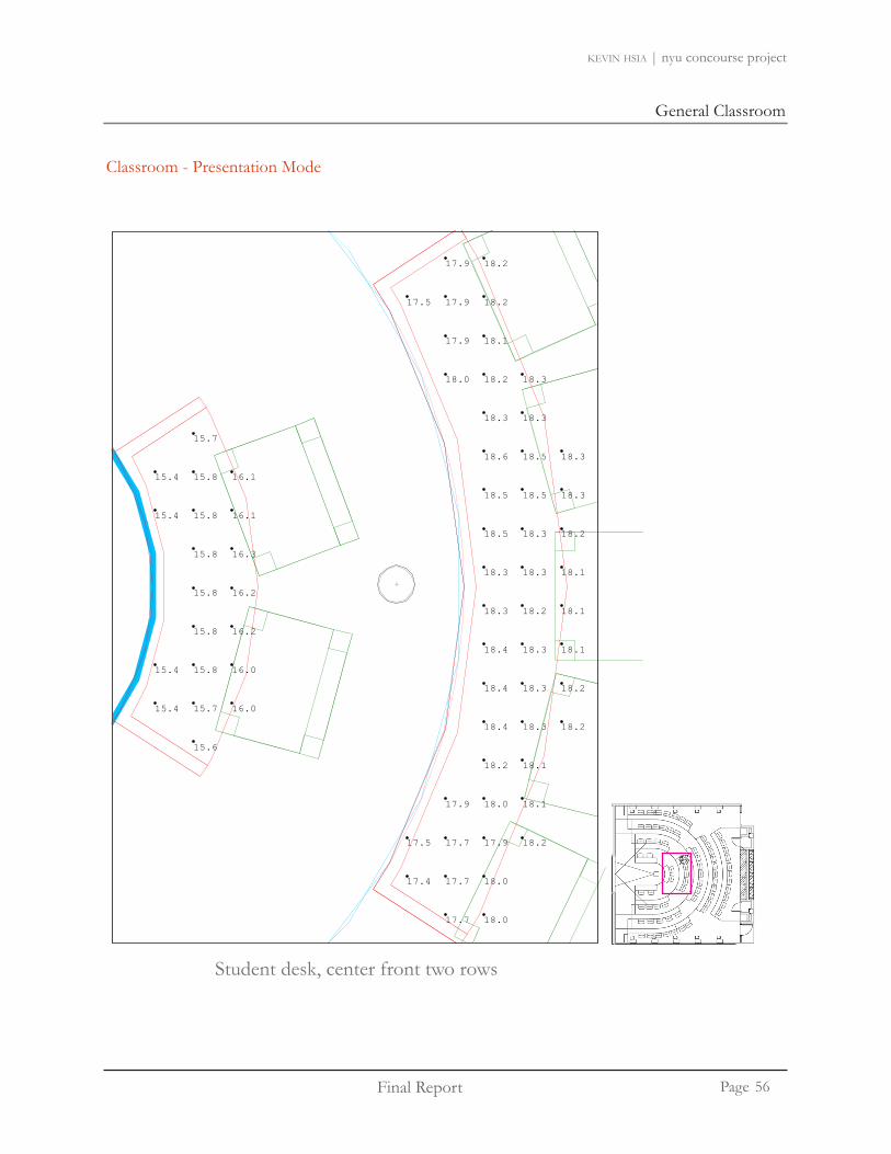
Classroom - Presentation Mode
Front of room, white board and presentation screen
Calculation Summary: Classroom: Presentation Mode
Label Calculation Type Units Avg Max Min Avg/Min
White Board 5 Illuminance Fc 2.33 2.60 2.20 1.06White Board 4 Illuminance Fc 2.23 2.40 2.00 1.12Table Level 1 Illuminance Fc 10.56 13.30 8.10 1.30Table Level 2 Illuminance Fc 12 50 16 30 7 70 1 62
Calculation Summary: Classroom: Presentation Mode
Table Level 2 Illuminance Fc 12.50 16.30 7.70 1.62Table Level 3 Illuminance Fc 12.69 18.30 6.10 2.08Table Level 4 Illuminance Fc 13.28 19.70 5.40 2.46Table Level 5 Illuminance Fc 17.35 16.40 14.20 1.22
Back Area Cabinet Illuminance Fc 10.36 16.40 3.30 3.14Side Wall Illuminance Fc 0.44 2.50 0.00 NA
1 ft away from board Illuminance Fc 1.32 1.60 1.00 1.321 ft away from board Illuminance Fc 1.32 1.60 1.00 1.323 ft away from board Illuminance Fc 1.27 1.40 1.10 1.15
Table 4 (center) Illuminance Fc 18.93 19.80 18.30 1.03Table 1 (center) Illuminance Fc 15.82 16.30 15.40 1.03Table 2 (center) Illuminance Fc 18.14 18.60 17.40 1.04
Label Calculation Type Units Avg Max Min Avg/Min
White Board 5 Illuminance Fc 26.29 29.50 23.50 1.12Projection Screen Illuminance Fc 21.69 26.30 15.90 1.36
Calculation Summary: Classroom: General Mode
jTable Level 1 Illuminance Fc 44.80 52.00 38.60 1.16Table Level 2 Illuminance Fc 38.79 50.60 31.80 1.36Table Level 3 Illuminance Fc 34.85 42.80 30.50 1.16Table Level 4 Illuminance Fc 32.05 35.10 30.00 1.22Table Level 5 Illuminance Fc 27.57 25.60 22.60 1.14
Back Area Cabinet Illuminance Fc 16.52 25.60 5.70 2.90Side Wall Illuminance Fc 2.17 11.90 0.00 NA
1 ft away from board Illuminance Fc 12.10 16.60 1.00 1.323 ft away from board Illuminance Fc 13.22 16.90 6.30 1.92
Table 4 (center) Illuminance Fc 30.40 31.90 29.20 1.04Table 3 (center) Illuminance Fc 30.65 31.70 29.70 1.03Table 2 (center) Illuminance Fc 31.29 31.90 30.80 1.02
2.3 2.4 2.5 2.5 2.6 2.6 2.5 2.4 2.3
2.3 2.3 2.4 2.5 2.5 2.5 2.4 2.4 2.3
2.2 2.3 2.4 2.4 2.5 2.4 2.4 2.3 2.2
2.2 2.2 2.3 2.3 2.4 2.3 2.3 2.2 2.2
2.2 2.2 2.3 2.3 2.3 2.3 2.3 2.2 2.2
2.2 2.2 2.3 2.3 2.3 2.3 2.2 2.2 2.2
2.3 2.3 2.4 2.4 2.4 2.4 2.3 2.2 2.2
2.3 2.3 2.3 2.4 2.4 2.3 2.2 2.2 2.2
2.3 2.3 2.3 2.3 2.3 2.3 2.2 2.2 2.1
2.2 2.2 2.3 2.3 2.3 2.2 2.2 2.1 2.1
2.1 2.1 2.2 2.3 2.3 2.2 2.2 2.1 2.1
2.0 2.1 2.1 2.2 2.2 2.2 2.1 2.1 2.0
8.1 8.6 9.1 9.5 9.9 8.1 8.6 9.1 9.5 9.9
7.7 8.2 8.6 9.1 9.5 7.7 8.1 8.6 9.1 9.5
6.2 6.8 7.4 8.1 8.7 9.2 9.7 10.1 6.2 6.8 7.4 8.1 8.7 9.2 9.7 10.2 6.1 6.7 7.4 8.0 8.6 9.2 9.7 10.1
5.5 6.0 6.6 7.2 7.7 8.1 8.5 8.9 9.4 5.4 6.0 6.5 7.1 7.6 8.1 8.4 8.9 9.4
1010
10
55
Final Report
General Classroom
Page
kevin hsia | nyu concourse project
Classroom - Presentation Mode
15.6
15.4 15.7 16.0
15.4 15.8 16.0
15.8 16.2
15.8 16.2
15.8 16.3
15.4 15.8 16.1
15.4 15.8 16.1
15.7
17.7 18.0
17.4 17.7 18.0
17.5 17.7 17.9 18.2
17.9 18.0 18.1
18.2 18.1
18.4 18.3 18.2
18.4 18.3 18.2
18.4 18.3 18.1
18.3 18.2 18.1
18.3 18.3 18.1
18.5 18.3 18.2
18.5 18.5 18.3
18.6 18.5 18.3
18.3 18.3
18.0 18.2 18.3
17.9 18.1
17.5 17.9 18.2
17.9 18.2
Student desk, center front two rows
56

Final Report
General Classroom
Page
kevin hsia | nyu concourse project
Classroom - Presentation Mode
19.7 19.2 18.8
19.2 18.8 18.4
18.5 18.1 17.8
17.6 17.5 17.3
17.0 17.0
16.4 16.4
16.0 15.9
15.8 15.6 15.5
15.7 15.3 15.1
15.9 15.3 14.7
16.2 15.3
17.5 16.7 15.8
17.9 17.1 16.2
18.8 18.0 17.2
18.8 17.9 17.1
19.2 18.7 17.9
18.9 18.6 17.8
18.5 18.5 18.1
17.9 17.8 17.4
17.9 17.5 17.2
17.7 17.4 16.8
17.3 16.7
18.6 18.7
18.6 18.6
18.6
18.7
18.9
19.2 19.1
19.1 19.1
19.1
18.9 19.0
18.7 18.7
18.5
18.6 18.5
19.4 18.8 18.5
19.5 18.9
19.6 19.4 18.9
19.7 19.6 19.4
19.6 19.5 19.2
19.3 19.3 19.2
18.7
15
student desk, center back two rows
57

Final Report
General Classroom
Page
kevin hsia | nyu concourse project
Classroom - Presentation Mode
plan, psuedo rendering
perspective, psuedo rendering
58

Final Report
General Classroom
Page
kevin hsia | nyu concourse project
Classroom - Design Summary
Overall, the lighting system for the classroom meets the design purpose of the classroom. The two lighting modes are able to provide a flexible lighting system to help enhance the learning experience.
For the general lecture mode lighting, the average illuminance level on the desks range from 27 fc to 45 fc, the lighting level does meet the suggested 30 fc by the IESNA handbook. Furthermore, an average of 26 fc is measured on the white board at the front of the room, which is also sufficient for viewing.
In terms of the presentation mode, an average of 3 fc is measured across the projection screens, which is less than the suggested 5 fc requirement from the IESNA DG-17. The table desk maintains an average of 10-17 fc for sufficient light levels to write in the dark.
The lighting system for the classroom is able to address the design criteria and meets the standards of the IESNA Handbook. The lighting design meets the ASHRAE Standard 90.1 2007. A total of 1914W was used, which is under the allowed 1946W.
59

Final Report
MBA Student Lounge
Page
kevin hsia | nyu concourse project
MBA Student Lounge
Located in the upper concourse, the MBA student lounge is home to the student’s of the master’s business administration program. The 2,100 sq.ft is divided into four sections. There is a pantry in the back, area for lounge tables and working counter, café style table area, and another lounge area. On the west walls, there are three sets of television monitors.
MBA Student Lounge Background Information
pantry
lounge
cafe style
lounge
wall with tv screen
wall with tv screen
60

MBA Student Lounge
Final Report
MBA Student Lounge
Page
kevin hsia | nyu concourse project
wall with tv screen
Materials for MBA Student Lounge
Type Description Finish Reflectance (assumed)
WallP-1 Eggshell Finish White 0.9
WD-3 Bamboo Patina panel Light Brown 0.4Wall Base Finish
CT-5 Gateway Ceramic Flooring Sterling Grey 0.5CT-5B Gateway Ceramic Flooring Sterling Grey 0.5FloorCT-5 Gateway Ceramic Flooring Sterling Grey 0.5
CT-5A Gateway Ceramic Flooring Sterling Grey 0.3RF-2 Rubber Sheet Flooring Fossil 0.3
CeilingACT-3 Acoustical panels White 0.9ACT-4 Acoustical panels white metal panels 0.9
Finishes for MBA Student Lounge
61

Final Report
MBA Student Lounge
Page
kevin hsia | nyu concourse project
Considerations and Criteria
Appearance of Space and LuminairesThe MBA student lounge is intended to create a relaxing atmosphere. The objective is to •
provide a comfortable space in which students can study, relax, and have a good time. The student lounge has a lounge area, tables, counter for computers, and pantry area.
Luminaires in the lounge can be artistic and decorative to emphasize the playfulness • and relaxing atmosphere. Non-uniform lighting can be addressed to help create visual interest in the space. The challenge is to attract people into a space with no daylight or windows.
Color Appearance (and color contrast)The MBA student lounge consist a variety of wall panels and finishes. •
Daylight integration and controlDaylight integration will not be a concern since there are no windows in the student • lounge.
Direct GlareDirect glare should be a concern to avoid any discomfort in the lounge area. Luminaires need to • be positioned to avoid glare.
Light Distribution surfacesThe idea is to light the space to make it relaxing and interesting so that students will • be attracted to the space. Light should not fall on the flat screen to minimize the glare reflection. •
62

MBA Student Lounge
Final Report
MBA Student Lounge
Page
kevin hsia | nyu concourse project
Considerations and Criteria
Light distribution on Task Plane (Uniformity)Light distribution on the tables and chairs will need to be uniform to provide a good • writing/reading environment. The pantry and computer counter will also need to provide uniform light levels.
Luminances of Room SurfacesAvoid high luminance levels on television screen• The hierarchy of the luminance levels is divided between the surfaces in which work will be done • (table, pantry table, computer table) and the decorative surfaces (bamboo patterns on the wall, ceiling). The decorative surfaces should have higher luminance values so that the attention will be on the architectural features. Based on the lighting impression studies done by John Flynn, there is a tendency for people to be in remote areas of lower intensity lighting [The luminance level on the tables, lounge table, computer tables, and pantry table will have enough lighting for reading and writing.
Surfaces CharacteristicsA few of the materials (ceiling [ACT-3 &ACT-4] and wall [P-1]) in the lounge have high re-• flectance so will help illuminance the space. The matte and satin finishes in the room provide a beautiful finish to the architecture of the space. The colors of the surfaces are white, sterling grey, metallic, bamboo brown and fossil white.
System Control and FlexibilityThe lighting system in the student lounge can be flexible for different modes (study • and entertainment/parties/special events). Occupancy sensors can be incorporated into the lighting system so energy can be saved when there is no one in the lounge.
Illuminance (Horizontal)[Study Mode] 30 fc –(IESNA Handbook: Reading Handwriting tasks- #2 pencil and • softer leads)
Energy 1.2 W/sq ft – (IESNA Standard 90.1-2007: Lounge/Recreation) •
63

Final Report
MBA Student Lounge
Page
kevin hsia | nyu concourse project
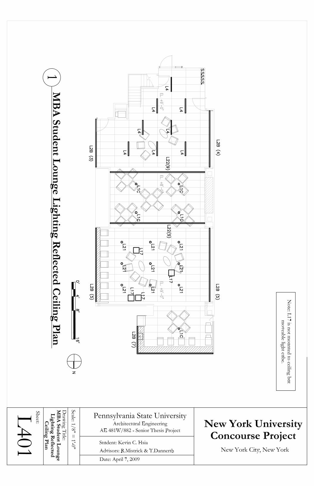
MBA Student Lounge Lighting Design
The challenge for the lighting design is to attract students down to the basement. There are no windows or skylights in the lounge. The ceiling heights in the basement are low (8ft and 9ft). The design emphasis will need to make the space feel comfortable and spacious.
Lighting the peripheralA combination of recessed fluorescent wallwashers and LEDs are used to light the walls and cove of the ceiling. By washing the walls, the occupant will perceive the space to be larger. The lighting design also avoids suspending luminaires since the lounge is not very high.
Relaxing Atmosphere The placement of the light boxes in zone 3 of the lounge creates a fun atmosphere in which students can play with the lighted furniture.
Reading/Writing Provide 30 fc on the tables.
64

MBA Student Lounge
Final Report
MBA Student Lounge
Page
kevin hsia | nyu concourse project
*Larger lighting plan can be found in Appendix I : L401
Lighting Reflected Ceiling Plan
65

Final Report
MBA Student Lounge
Page
kevin hsia | nyu concourse project
Image Type Manufacture Fixture Description Watt Quantity Lamp Ballast Model
L1C Kurt Versen Downlight
Recessed compact
fluorescent downlight
36 5 CF32DT/E/IN/835/ECO Osram Sylvania
Advance IDL-2S26-M5-
BSP926
L2BSelux M100
Super Recessed
Recessed linear fluorescent wall
washer31 24 FP28/835/ECO Osram
Sylvania
Advance ICN-2S28-
N@120
M1B1S-1T5-SD-PM-68-SV-277
Lighting Fixture Schedule for MBA Student Lounge
L4 Selux M60
Recessed linear fluorescent 31 8 FP28/835/ECO Osram
Sylvania
Advance ICN-2S28-
N@120
M6R1-1T5-MA-PM-004-SV-277
L17Daifuku Designs
Lite Cube
Light-seats in white
polyethylene 13 4 CF19EL/SUPER/850BL
Osram Sylvania Integral Ballast Lite Cube
L21Lightolier
Vetro Downlight
Architectural Decorative
Vetro Downlight
50 9 50MR16/IR/FL35/C Osram Sylvania - -
L22 io line 1.5
Led based linear flood 28 18 LED Driver series 1.5
Type Mainenance Category Dirt Conditions Cleaning
Period LDD Initial Lumens
Mean Lumens LLD BF Total
LLF
L1C IV Clean 12 months 0.88 2400 2064 0.86 1 0.76L2B IV Clean 12 months 0.88 2900 2697 0.93 1.05 0.86L4 IV Clean 12 months 0.88 2900 2697 0.93 1.05 0.86L17 V Clean 12 months 0.88 1200 960 0.80 1 0.70L21 IV Clean 12 months 0.88 800 - - 1 0.88L22 VI Clean 12 months 0.96 29 - - 1 0.96
Light Loss Factor for MBA Student Lounge
66

MBA Student Lounge
Final Report
MBA Student Lounge
Page
kevin hsia | nyu concourse project
Type Manufacture Watt Quantity Watt Energy Allowed
L1C Kurt Versen Downlight 36 5 180 2100 sq.ft x 1.2W/sq.ft
L2B Selux M100 Super Recessed 31 24 744
L4 Selux M60 31 8 248
L17 Daifuku Designs Lite Cube 13 4 52
L21 Lightolier Vetro Downlight 50 9 450
L22 io line 1.5 28 18 504
2178 2520
1.04 1.2
Red - DesignedBlue - IESNA recommended
Energy Calculation for MBA Student Lounge
Consumed PowerPower Density
MBA Student Lounge Controls
The control system of the student lounge will consist of 5 switches for 5 zones. No dimming is required in the space. There are no preset zones. The zones are divided as following:
Zone 1 - Cove lighting in ceiling and perimeter wallwash fluorescents Zone 2 - Recessed fluorescents in lounge zone 1 (near the stairs)Zone 3 - Downlights in lounge zone 2 (table area)Zone 4 - Ceiling mount luminaires in lounge zone 3 (with computer counter)Zone 5 - Pantry lighting
Energy
67

Final Report
MBA Student Lounge
Page
kevin hsia | nyu concourse project
Lounge Zone 1
L7(6)
B)
4.2 5.4 6.9 8.4 9.5 9.3
5.2 6.8 8.7 10.7 11.9 11.8
6.3 8.4 10.6 12.7 14.1 14.3
7.6 9.9 12.4 14.4 15.7 16.1 15.8 13.8 10.0
8.7 11.1 13.7 15.6 16.8 17.5 17.6 16.5 12.6
8.6 11.3 14.1 16.2 17.5 18.4 18.8 18.1 17.0 16.7 15.0
8.2 10.9 13.7 16.2 17.9 18.9 19.2 19.0 18.5 17.5 15.6
8.0 10.5 13.4 16.1 18.2 19.2 19.5 19.5 19.1 18.0 16.3 12.4 11.8 13.0 14.9
8.1 10.6 13.5 16.1 18.1 19.1 19.5 19.6 19.3 18.4 17.0 14.3 14.1 15.6 17.7
8.3 11.0 13.7 16.0 17.5 18.6 19.2 19.3 19.0 18.4 17.5 15.7 15.6 17.2 19.5
8.4 11.1 13.7 15.4 16.6 17.5 18.2 18.3 18.0 17.7 17.3 16.2 16.1 17.6 19.9
7.9 10.3 12.5 13.9 14.8 15.5 16.0 16.2 16.0 15.9 15.8 15.2 15.3 16.7 18.8
6.9 9.2 11.2 12.5 13.1 13.7 14.1 14.4 14.4 14.4 14.2 13.7 13.5 14.5 16.2
L21L21L21
L21 L21 L21
L21L21L21
L2B(5)
(7)L2B
L7(6)
L7(6)
(5)L2B
L2B(3)
L2B(4)
EL. +21'-0 3/4"
19.6 20.2
27.1 27.9 25.6
33.6
9.0 11.0 11.7 7.6 11.4 10.4 8.4
5.9 9.1 12.9 8.2 8.9 14.0 12.2 11.4
7.7 11.0 15.7 19.4 20.4 17.9 15.5 15.1
9.9 13.3 18.3 22.4 23.7 23.5 21.1 18.9 19.1
12.8 16.3 20.8 24.7 26.7 26.2 24.0 22.5 22.9
17.7
23.9
28.1
30.3
31.2
31.4
31.1
30.1
27.7
23.2
16.4 14.3 14.5 18.1 16.8 11.0 11.1 16.1 16.3 11.4 11.5 16.6 17.3 13.6 13.5
18.9 15.7 16.6 21.6 19.8 11.2 11.9 18.7 18.5 11.5 12.2 20.1 21.6 17.1 16.3
20.7 16.8 15.3 18.7 16.7 9.9 9.6 15.4 15.3 9.5 10.1 17.2 19.3 16.6 18.2
21.6 17.6 15.9 19.0 16.8 9.9 9.4 15.3 15.2 9.6 10.3 17.3 19.6 17.3 19.5
22.0 19.0 22.7 22.8 20.2 11.8 11.5 18.5 18.5 11.9 12.5 20.6 23.0 19.6 20.1
22.0 19.8 79.5 12.4 17.1 9.7 9.7 15.5 15.5 22.1 13.8 17.6 19.9 17.7 20.0
21.2 17.7 17.8 9.9 10.8 9.0 27.1 14.0 16.9 19.2 17.1 19.5
19.6 15.8 32.1 28.5 12.4 11.7 77.3 11.3 19.4 21.7 18.2 18.4
17.3 14.3 13.6 18.4 17.8 10.1 10.1 15.9 13.3 5.0 8.3 14.8 17.0 14.9 16.4
14.5 12.4 10.8 10.6 9.9 8.0 7.0 7.2 6.3 5.2 5.6 7.5 9.3 10.9 13.7
4.2 5.4 6.9 8.4 9.5 9.3
5.2 6.8 8.7 10.7 11.9 11.8
6.3 8.4 10.6 12.7 14.1 14.3
7.6 9.9 12.4 14.4 15.7 16.1 15.8 13.8 10.0
8.7 11.1 13.7 15.6 16.8 17.5 17.6 16.5 12.6
8.6 11.3 14.1 16.2 17.5 18.4 18.8 18.1 17.0 16.7 15.0
8.2 10.9 13.7 16.2 17.9 18.9 19.2 19.0 18.5 17.5 15.6
8.0 10.5 13.4 16.1 18.2 19.2 19.5 19.5 19.1 18.0 16.3 12.4 11.8 13.0 14.9
8.1 10.6 13.5 16.1 18.1 19.1 19.5 19.6 19.3 18.4 17.0 14.3 14.1 15.6 17.7
8.3 11.0 13.7 16.0 17.5 18.6 19.2 19.3 19.0 18.4 17.5 15.7 15.6 17.2 19.5
8.4 11.1 13.7 15.4 16.6 17.5 18.2 18.3 18.0 17.7 17.3 16.2 16.1 17.6 19.9
7.9 10.3 12.5 13.9 14.8 15.5 16.0 16.2 16.0 15.9 15.8 15.2 15.3 16.7 18.8
6.9 9.2 11.2 12.5 13.1 13.7 14.1 14.4 14.4 14.4 14.2 13.7 13.5 14.5 16.2
6.8 11.0 15.2 17.5 9.6 17.4 19.3 19.9 20.1 19.7 6.3 8.2
7.0 13.0 18.0 10.2 21.2 22.6 22.8 25.0 23.5 20.2 15.2 8.8
7.1 13.6 19.0 21.6 21.8 22.2 20.7 22.2 24.1 24.6 21.2 15.5 8.8
7.0 13.0 19.4 22.5 21.1 21.2 24.5 25.3 24.9 22.1 15.0 8.4
7.2 13.8 19.3 21.6 21.4 21.7 19.7 21.0 23.4 24.7 21.4 15.4 8.6
7.9 14.2 20.9 21.3 22.2 22.0 25.2 23.6 8.6
9.6 13.6 6.7 7.2 17.4 17.2 18.8 19.4 20.1 19.5 6.7 5.6 8.1
1.7
2.8 0.4 2.3
3.1
1.6
2.1 0.4 2.1
2.8
3.5
1.7 0.4 2.9
1.6
22.2 23.5
25.5 26.9
28.5 29.9
31.5 32.5
34.3 34.6
17.6 20.2 22.5 24.3 26.1 27.9 29.4 30.8 31.9 32.5 32.7 32.4 31.9 31.4 31.2 31.3 32.2 33.5 35.0 36.2 35.6
19.0 22.0 24.6 26.7 28.3 29.7 31.0 32.0 32.8 33.3 33.5 33.5 33.3 33.1 33.0 33.4 34.1 34.8 35.7 36.0 34.8
L21L21L21
L21 L21 L21
L21L21L21
L2B(5)
L7(6)
(5)L2B
17.7
23.9
28.1
30.3
31.2
31.4
31.1
30.1
27.7
23.2
16.4 14.3 14.5 18.1 16.8 11.0 11.1 16.1 16.3 11.4 11.5 16.6 17.3 13.6 13.5
18.9 15.7 16.6 21.6 19.8 11.2 11.9 18.7 18.5 11.5 12.2 20.1 21.6 17.1 16.3
20.7 16.8 15.3 18.7 16.7 9.9 9.6 15.4 15.3 9.5 10.1 17.2 19.3 16.6 18.2
21.6 17.6 15.9 19.0 16.8 9.9 9.4 15.3 15.2 9.6 10.3 17.3 19.6 17.3 19.5
22.0 19.0 22.7 22.8 20.2 11.8 11.5 18.5 18.5 11.9 12.5 20.6 23.0 19.6 20.1
22.0 19.8 79.5 12.4 17.1 9.7 9.7 15.5 15.5 22.1 13.8 17.6 19.9 17.7 20.0
21.2 17.7 17.8 9.9 10.8 9.0 27.1 14.0 16.9 19.2 17.1 19.5
19.6 15.8 32.1 28.5 12.4 11.7 77.3 11.3 19.4 21.7 18.2 18.4
17.3 14.3 13.6 18.4 17.8 10.1 10.1 15.9 13.3 5.0 8.3 14.8 17.0 14.9 16.4
14.5 12.4 10.8 10.6 9.9 8.0 7.0 7.2 6.3 5.2 5.6 7.5 9.3 10.9 13.7
L21L21L21
L21 L21 L21
L21L21L21
L2B(5)
(7)L2B
L7(6)
L7(6)
(5)L2B
L2B(3)
L2B(4)
EL. +21'-0 3/4"
19.6 20.2
27.1 27.9 25.6
33.6
9.0 11.0 11.7 7.6 11.4 10.4 8.4
5.9 9.1 12.9 8.2 8.9 14.0 12.2 11.4
7.7 11.0 15.7 19.4 20.4 17.9 15.5 15.1
9.9 13.3 18.3 22.4 23.7 23.5 21.1 18.9 19.1
12.8 16.3 20.8 24.7 26.7 26.2 24.0 22.5 22.9
17.7
23.9
28.1
30.3
31.2
31.4
31.1
30.1
27.7
23.2
16.4 14.3 14.5 18.1 16.8 11.0 11.1 16.1 16.3 11.4 11.5 16.6 17.3 13.6 13.5
18.9 15.7 16.6 21.6 19.8 11.2 11.9 18.7 18.5 11.5 12.2 20.1 21.6 17.1 16.3
20.7 16.8 15.3 18.7 16.7 9.9 9.6 15.4 15.3 9.5 10.1 17.2 19.3 16.6 18.2
21.6 17.6 15.9 19.0 16.8 9.9 9.4 15.3 15.2 9.6 10.3 17.3 19.6 17.3 19.5
22.0 19.0 22.7 22.8 20.2 11.8 11.5 18.5 18.5 11.9 12.5 20.6 23.0 19.6 20.1
22.0 19.8 79.5 12.4 17.1 9.7 9.7 15.5 15.5 22.1 13.8 17.6 19.9 17.7 20.0
21.2 17.7 17.8 9.9 10.8 9.0 27.1 14.0 16.9 19.2 17.1 19.5
19.6 15.8 32.1 28.5 12.4 11.7 77.3 11.3 19.4 21.7 18.2 18.4
17.3 14.3 13.6 18.4 17.8 10.1 10.1 15.9 13.3 5.0 8.3 14.8 17.0 14.9 16.4
14.5 12.4 10.8 10.6 9.9 8.0 7.0 7.2 6.3 5.2 5.6 7.5 9.3 10.9 13.7
4.2 5.4 6.9 8.4 9.5 9.3
5.2 6.8 8.7 10.7 11.9 11.8
6.3 8.4 10.6 12.7 14.1 14.3
7.6 9.9 12.4 14.4 15.7 16.1 15.8 13.8 10.0
8.7 11.1 13.7 15.6 16.8 17.5 17.6 16.5 12.6
8.6 11.3 14.1 16.2 17.5 18.4 18.8 18.1 17.0 16.7 15.0
8.2 10.9 13.7 16.2 17.9 18.9 19.2 19.0 18.5 17.5 15.6
8.0 10.5 13.4 16.1 18.2 19.2 19.5 19.5 19.1 18.0 16.3 12.4 11.8 13.0 14.9
8.1 10.6 13.5 16.1 18.1 19.1 19.5 19.6 19.3 18.4 17.0 14.3 14.1 15.6 17.7
8.3 11.0 13.7 16.0 17.5 18.6 19.2 19.3 19.0 18.4 17.5 15.7 15.6 17.2 19.5
8.4 11.1 13.7 15.4 16.6 17.5 18.2 18.3 18.0 17.7 17.3 16.2 16.1 17.6 19.9
7.9 10.3 12.5 13.9 14.8 15.5 16.0 16.2 16.0 15.9 15.8 15.2 15.3 16.7 18.8
6.9 9.2 11.2 12.5 13.1 13.7 14.1 14.4 14.4 14.4 14.2 13.7 13.5 14.5 16.2
6.8 11.0 15.2 17.5 9.6 17.4 19.3 19.9 20.1 19.7 6.3 8.2
7.0 13.0 18.0 10.2 21.2 22.6 22.8 25.0 23.5 20.2 15.2 8.8
7.1 13.6 19.0 21.6 21.8 22.2 20.7 22.2 24.1 24.6 21.2 15.5 8.8
7.0 13.0 19.4 22.5 21.1 21.2 24.5 25.3 24.9 22.1 15.0 8.4
7.2 13.8 19.3 21.6 21.4 21.7 19.7 21.0 23.4 24.7 21.4 15.4 8.6
7.9 14.2 20.9 21.3 22.2 22.0 25.2 23.6 8.6
9.6 13.6 6.7 7.2 17.4 17.2 18.8 19.4 20.1 19.5 6.7 5.6 8.1
1.7
2.8 0.4 2.3
3.1
1.6
2.1 0.4 2.1
2.8
3.5
1.7 0.4 2.9
1.6
22.2 23.5
25.5 26.9
28.5 29.9
31.5 32.5
34.3 34.6
17.6 20.2 22.5 24.3 26.1 27.9 29.4 30.8 31.9 32.5 32.7 32.4 31.9 31.4 31.2 31.3 32.2 33.5 35.0 36.2 35.6
19.0 22.0 24.6 26.7 28.3 29.7 31.0 32.0 32.8 33.3 33.5 33.5 33.3 33.1 33.0 33.4 34.1 34.8 35.7 36.0 34.8
Lounge Zone 2 (Table Area)
68

MBA Student Lounge
Final Report
MBA Student Lounge
Page
kevin hsia | nyu concourse project
Lounge Zone 3 (with computer counter)
L21L21L21
L21 L21 L21
L21L21L21
L2B(5)
L7(6)
(5)L2B
17.7
23.9
28.1
30.3
31.2
31.4
31.1
30.1
27.7
23.2
16.4 14.3 14.5 18.1 16.8 11.0 11.1 16.1 16.3 11.4 11.5 16.6 17.3 13.6 13.5
18.9 15.7 16.6 21.6 19.8 11.2 11.9 18.7 18.5 11.5 12.2 20.1 21.6 17.1 16.3
20.7 16.8 15.3 18.7 16.7 9.9 9.6 15.4 15.3 9.5 10.1 17.2 19.3 16.6 18.2
21.6 17.6 15.9 19.0 16.8 9.9 9.4 15.3 15.2 9.6 10.3 17.3 19.6 17.3 19.5
22.0 19.0 22.7 22.8 20.2 11.8 11.5 18.5 18.5 11.9 12.5 20.6 23.0 19.6 20.1
22.0 19.8 79.5 12.4 17.1 9.7 9.7 15.5 15.5 22.1 13.8 17.6 19.9 17.7 20.0
21.2 17.7 17.8 9.9 10.8 9.0 27.1 14.0 16.9 19.2 17.1 19.5
19.6 15.8 32.1 28.5 12.4 11.7 77.3 11.3 19.4 21.7 18.2 18.4
17.3 14.3 13.6 18.4 17.8 10.1 10.1 15.9 13.3 5.0 8.3 14.8 17.0 14.9 16.4
14.5 12.4 10.8 10.6 9.9 8.0 7.0 7.2 6.3 5.2 5.6 7.5 9.3 10.9 13.7
L21L21L21
L21 L21 L21
L21L21L21
L2B(5)
(7)L2B
L7(6)
L7(6)
(5)L2B
L2B(3)
L2B(4)
EL. +21'-0 3/4"
19.6 20.2
27.1 27.9 25.6
33.6
9.0 11.0 11.7 7.6 11.4 10.4 8.4
5.9 9.1 12.9 8.2 8.9 14.0 12.2 11.4
7.7 11.0 15.7 19.4 20.4 17.9 15.5 15.1
9.9 13.3 18.3 22.4 23.7 23.5 21.1 18.9 19.1
12.8 16.3 20.8 24.7 26.7 26.2 24.0 22.5 22.9
17.7
23.9
28.1
30.3
31.2
31.4
31.1
30.1
27.7
23.2
16.4 14.3 14.5 18.1 16.8 11.0 11.1 16.1 16.3 11.4 11.5 16.6 17.3 13.6 13.5
18.9 15.7 16.6 21.6 19.8 11.2 11.9 18.7 18.5 11.5 12.2 20.1 21.6 17.1 16.3
20.7 16.8 15.3 18.7 16.7 9.9 9.6 15.4 15.3 9.5 10.1 17.2 19.3 16.6 18.2
21.6 17.6 15.9 19.0 16.8 9.9 9.4 15.3 15.2 9.6 10.3 17.3 19.6 17.3 19.5
22.0 19.0 22.7 22.8 20.2 11.8 11.5 18.5 18.5 11.9 12.5 20.6 23.0 19.6 20.1
22.0 19.8 79.5 12.4 17.1 9.7 9.7 15.5 15.5 22.1 13.8 17.6 19.9 17.7 20.0
21.2 17.7 17.8 9.9 10.8 9.0 27.1 14.0 16.9 19.2 17.1 19.5
19.6 15.8 32.1 28.5 12.4 11.7 77.3 11.3 19.4 21.7 18.2 18.4
17.3 14.3 13.6 18.4 17.8 10.1 10.1 15.9 13.3 5.0 8.3 14.8 17.0 14.9 16.4
14.5 12.4 10.8 10.6 9.9 8.0 7.0 7.2 6.3 5.2 5.6 7.5 9.3 10.9 13.7
4.2 5.4 6.9 8.4 9.5 9.3
5.2 6.8 8.7 10.7 11.9 11.8
6.3 8.4 10.6 12.7 14.1 14.3
7.6 9.9 12.4 14.4 15.7 16.1 15.8 13.8 10.0
8.7 11.1 13.7 15.6 16.8 17.5 17.6 16.5 12.6
8.6 11.3 14.1 16.2 17.5 18.4 18.8 18.1 17.0 16.7 15.0
8.2 10.9 13.7 16.2 17.9 18.9 19.2 19.0 18.5 17.5 15.6
8.0 10.5 13.4 16.1 18.2 19.2 19.5 19.5 19.1 18.0 16.3 12.4 11.8 13.0 14.9
8.1 10.6 13.5 16.1 18.1 19.1 19.5 19.6 19.3 18.4 17.0 14.3 14.1 15.6 17.7
8.3 11.0 13.7 16.0 17.5 18.6 19.2 19.3 19.0 18.4 17.5 15.7 15.6 17.2 19.5
8.4 11.1 13.7 15.4 16.6 17.5 18.2 18.3 18.0 17.7 17.3 16.2 16.1 17.6 19.9
7.9 10.3 12.5 13.9 14.8 15.5 16.0 16.2 16.0 15.9 15.8 15.2 15.3 16.7 18.8
6.9 9.2 11.2 12.5 13.1 13.7 14.1 14.4 14.4 14.4 14.2 13.7 13.5 14.5 16.2
6.8 11.0 15.2 17.5 9.6 17.4 19.3 19.9 20.1 19.7 6.3 8.2
7.0 13.0 18.0 10.2 21.2 22.6 22.8 25.0 23.5 20.2 15.2 8.8
7.1 13.6 19.0 21.6 21.8 22.2 20.7 22.2 24.1 24.6 21.2 15.5 8.8
7.0 13.0 19.4 22.5 21.1 21.2 24.5 25.3 24.9 22.1 15.0 8.4
7.2 13.8 19.3 21.6 21.4 21.7 19.7 21.0 23.4 24.7 21.4 15.4 8.6
7.9 14.2 20.9 21.3 22.2 22.0 25.2 23.6 8.6
9.6 13.6 6.7 7.2 17.4 17.2 18.8 19.4 20.1 19.5 6.7 5.6 8.1
1.7
2.8 0.4 2.3
3.1
1.6
2.1 0.4 2.1
2.8
3.5
1.7 0.4 2.9
1.6
22.2 23.5
25.5 26.9
28.5 29.9
31.5 32.5
34.3 34.6
17.6 20.2 22.5 24.3 26.1 27.9 29.4 30.8 31.9 32.5 32.7 32.4 31.9 31.4 31.2 31.3 32.2 33.5 35.0 36.2 35.6
19.0 22.0 24.6 26.7 28.3 29.7 31.0 32.0 32.8 33.3 33.5 33.5 33.3 33.1 33.0 33.4 34.1 34.8 35.7 36.0 34.8
L7(6)
L7(6)
EL. +21'-0 3/4"
38.5
31.8 37.4 36.9
28.9
27.5
38.3 34.6 25.4
35.9
33.7
38.6 32.2 20.6
24.8
6.8 11.0 15.2 17.5 9.6 17.4 19.3 19.9 20.1 19.6 6.3 8.2
7.0 13.0 18.0 10.2 21.2 22.6 22.8 25.0 23.5 20.1 15.2 8.8
7.1 13.6 19.0 21.6 21.8 22.2 20.7 22.2 24.2 24.6 21.2 15.5 8.8
7.0 13.0 19.4 22.5 21.1 21.2 24.5 25.4 24.9 22.1 15.0 8.4
7.2 13.8 19.3 21.6 21.4 21.7 19.7 21.0 23.4 24.7 21.4 15.4 8.6
7.9 14.2 20.9 21.3 22.2 22.0 25.2 23.7 8.5
9.6 13.6 6.7 7.2 17.4 17.2 18.8 19.4 20.1 19.5 6.7 5.6 8.1
L21L21L21
L21 L21 L21
L21L21L21
L2B(5)
(7)L2B
L7(6)
L7(6)
(5)L2B
L2B(3)
L2B(4)
EL. +21'-0 3/4"
19.6 20.2
27.1 27.9 25.6
33.6
9.0 11.0 11.7 7.6 11.4 10.4 8.4
5.9 9.1 12.9 8.2 8.9 14.0 12.2 11.4
7.7 11.0 15.7 19.4 20.4 17.9 15.5 15.1
9.9 13.3 18.3 22.4 23.7 23.5 21.1 18.9 19.1
12.8 16.3 20.8 24.7 26.7 26.2 24.0 22.5 22.9
17.7
23.9
28.1
30.3
31.2
31.4
31.1
30.1
27.7
23.2
16.4 14.3 14.5 18.1 16.8 11.0 11.1 16.1 16.3 11.4 11.5 16.6 17.3 13.6 13.5
18.9 15.7 16.6 21.6 19.8 11.2 11.9 18.7 18.5 11.5 12.2 20.1 21.6 17.1 16.3
20.7 16.8 15.3 18.7 16.7 9.9 9.6 15.4 15.3 9.5 10.1 17.2 19.3 16.6 18.2
21.6 17.6 15.9 19.0 16.8 9.9 9.4 15.3 15.2 9.6 10.3 17.3 19.6 17.3 19.5
22.0 19.0 22.7 22.8 20.2 11.8 11.5 18.5 18.5 11.9 12.5 20.6 23.0 19.6 20.1
22.0 19.8 79.5 12.4 17.1 9.7 9.7 15.5 15.5 22.1 13.8 17.6 19.9 17.7 20.0
21.2 17.7 17.8 9.9 10.8 9.0 27.1 14.0 16.9 19.2 17.1 19.5
19.6 15.8 32.1 28.5 12.4 11.7 77.3 11.3 19.4 21.7 18.2 18.4
17.3 14.3 13.6 18.4 17.8 10.1 10.1 15.9 13.3 5.0 8.3 14.8 17.0 14.9 16.4
14.5 12.4 10.8 10.6 9.9 8.0 7.0 7.2 6.3 5.2 5.6 7.5 9.3 10.9 13.7
4.2 5.4 6.9 8.4 9.5 9.3
5.2 6.8 8.7 10.7 11.9 11.8
6.3 8.4 10.6 12.7 14.1 14.3
7.6 9.9 12.4 14.4 15.7 16.1 15.8 13.8 10.0
8.7 11.1 13.7 15.6 16.8 17.5 17.6 16.5 12.6
8.6 11.3 14.1 16.2 17.5 18.4 18.8 18.1 17.0 16.7 15.0
8.2 10.9 13.7 16.2 17.9 18.9 19.2 19.0 18.5 17.5 15.6
8.0 10.5 13.4 16.1 18.2 19.2 19.5 19.5 19.1 18.0 16.3 12.4 11.8 13.0 14.9
8.1 10.6 13.5 16.1 18.1 19.1 19.5 19.6 19.3 18.4 17.0 14.3 14.1 15.6 17.7
8.3 11.0 13.7 16.0 17.5 18.6 19.2 19.3 19.0 18.4 17.5 15.7 15.6 17.2 19.5
8.4 11.1 13.7 15.4 16.6 17.5 18.2 18.3 18.0 17.7 17.3 16.2 16.1 17.6 19.9
7.9 10.3 12.5 13.9 14.8 15.5 16.0 16.2 16.0 15.9 15.8 15.2 15.3 16.7 18.8
6.9 9.2 11.2 12.5 13.1 13.7 14.1 14.4 14.4 14.4 14.2 13.7 13.5 14.5 16.2
6.8 11.0 15.2 17.5 9.6 17.4 19.3 19.9 20.1 19.7 6.3 8.2
7.0 13.0 18.0 10.2 21.2 22.6 22.8 25.0 23.5 20.2 15.2 8.8
7.1 13.6 19.0 21.6 21.8 22.2 20.7 22.2 24.1 24.6 21.2 15.5 8.8
7.0 13.0 19.4 22.5 21.1 21.2 24.5 25.3 24.9 22.1 15.0 8.4
7.2 13.8 19.3 21.6 21.4 21.7 19.7 21.0 23.4 24.7 21.4 15.4 8.6
7.9 14.2 20.9 21.3 22.2 22.0 25.2 23.6 8.6
9.6 13.6 6.7 7.2 17.4 17.2 18.8 19.4 20.1 19.5 6.7 5.6 8.1
1.7
2.8 0.4 2.3
3.1
1.6
2.1 0.4 2.1
2.8
3.5
1.7 0.4 2.9
1.6
22.2 23.5
25.5 26.9
28.5 29.9
31.5 32.5
34.3 34.6
17.6 20.2 22.5 24.3 26.1 27.9 29.4 30.8 31.9 32.5 32.7 32.4 31.9 31.4 31.2 31.3 32.2 33.5 35.0 36.2 35.6
19.0 22.0 24.6 26.7 28.3 29.7 31.0 32.0 32.8 33.3 33.5 33.5 33.3 33.1 33.0 33.4 34.1 34.8 35.7 36.0 34.8
Pantry
69
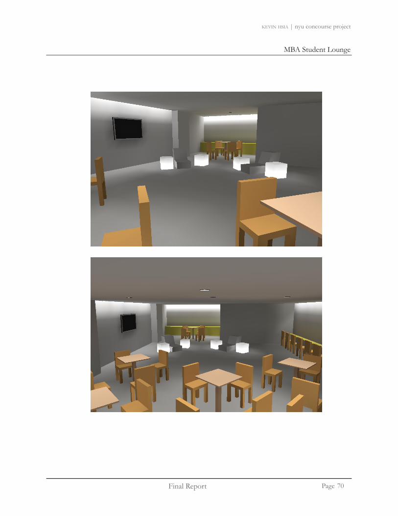
Final Report
MBA Student Lounge
Page
kevin hsia | nyu concourse project
70

MBA Student Lounge
Final Report
MBA Student Lounge
Page
kevin hsia | nyu concourse project
71

Final Report
MBA Student Lounge
Page
kevin hsia | nyu concourse project
Label Calculation Type Units Avg Max Min Avg/Min Max/
MinPantry Table Illuminance Fc 25.67 33.60 19.60 1.31 1.71
Pantry Counter Illuminance Fc 30.20 36.20 17.60 1.72 2.06Pantry Illuminance Fc 15.65 26.70 5.90 2.65 4.53
Computer Counter Illuminance Fc 27.47 31.40 17.70 1.55 1.77
Lounge Z1 (Near stairs)Illuminance Fc 14.42 19.90 4.20 3.43 4.74
Lounge Z2 (Table Area)Illuminance Fc 16.91 25.40 5.60 3.02 4.54
Lounge Z3 (Near Computer Station) Illuminance Fc 16.34 79.50 5.00 3.27 15.90
Table 3 Illuminance Fc 29.98 38.60 20.60 1.46 1.87Table 2 (center) Illuminance Fc 32.34 38.30 25.40 1.27 1.51Table 1 (center) Illuminance Fc 34.70 38.50 28.90 1.20 1.33
TV Screen Illuminance Fc 6.45 7.10 5.80 1.11 1.22
Calculation Summary: MBA Student Lounge
MBA Student Lounge Design Summary
Overall, the lighting system for the MBA Student Lounge meets the design purpose of the classroom. The lighting design is able to make the lounge feel spacious and pleasant. By washing the walls of the lounge and recessing the luminaires, the space feels larger. The proposed light boxes helps creates a relaxing and fun atmosphere in the space. An average of 30-35 fc is provided on the desk for writing/reading purposes. The lighting design meets the ASHRAE Standard 90.1 2007. A total of 1914W was used, which is under the allowed 1946W.
72

Final Report
Electrical - Gould Plaza
kevin hsia | nyu concourse project
Page
Background Information
The 27,360 sq. ft. plaza consists of benches and tress for social gathering. Gould plaza is surrounded by Tisch Hall, Weaver Hall, and the Kaufman Center. The space is used to provide a relaxing environment for students to interact.
Lighting Design
The lighting design encompasses a mixture of light poles, light rails, step lights, downlights, and custom ingrade NYU logo. The backlit NYU logo is created to reinforce the NYU school identity and pride. The lighting in Gould Plaza focuses on light the entrance/exits of the surrounding buildings to provide a safe environment for students to walk at night.
stairs leading to nyu campus
KMC entrance
tisch hall entrance
skylights
Gould Plaza
weaver hall
Gould Plaza: Electrical Redesign
Electrical Design
The electrical redesign involves dividing the lighting into different zones. Instead of creating a new panelboard for the outdoor lighting, the lighting loads will share the same panelboard as the Tisch Lobby lighting. A total of 9 circuits will be designed for this space.
73
outdoor seating

Final Report
Electrical - Gould Plaza
kevin hsia | nyu concourse project
Page
Electrical Panel
VOLTAGE: MIN. C/B AIC: SIZE/TYPE BUS: OPTIONS:
SIZE/TYPE MAIN:
DESCRIPTION LOCATION LOAD (WATTS) C/B SIZE POS. NO. A B C POS. NO. C/B SIZE LOAD (WATTS) LOCATION DESCRIPTION
Lighting LOBBY 216 20A/1P 1 * 2 20A/1P 180 LOBBY Lighting Lighting LOBBY 180 20A/1P 3 * 4 20A/1P 180 LOBBY Lighting Lighting LOBBY 216 20A/1P 5 * 6 20A/1P 252 LOBBY Lighting Lighting LOBBY 546 20A/1P 7 * 8 20A/1P 546 LOBBY Lighting Lighting LOBBY 184 20A/1P 9 * 10 20A/1P 1521 LOBBY Lighting Lighting LOBBY 975 20A/1P 11 * 12 20A/1P 81 LOBBY Lighting Lighting PLAZA 1073 20A/1P 13 * 14 20A/1P 260 PLAZA Lighting Lighting PLAZA 312 20A/1P 15 * 16 20A/1P 480 PLAZA Lighting Lighting PLAZA 459 20A/1P 17 * 18 20A/1P 234 PLAZA Lighting Lighting PLAZA 180 20A/1P 19 * 20 20A/1P 459 PLAZA Lighting Lighting PLAZA 392 20A/1P 21 * 22 20A/1P 0
0 20A/1P 23 * 24 20A/1P 0 0 20A/1P 25 * 26 20A/1P 0 0 20A/1P 27 * 28 20A/1P 0 0 20A/1P 29 * 30 20A/1P 0 0 20A/1P 31 * 32 20A/1P 0 0 20A/1P 33 * 34 20A/1P 0 0 20A/1P 35 * 36 20A/1P 0
PNL RP-1A LOBBY 9080 80/3P 37 * 38 20A/1P 0 0 0PNL RP-1A LOBBY 8980 - 39 * 40 20A/1P 0 0 0PNL RP-1A LOBBY 9020 - 41 * 42 20A/1P 0
CONNECTED LOAD (KW) - A 12.54 TOTAL DESIGN LOAD (KW) 43.21
CONNECTED LOAD (KW) - B 12.23 POWER FACTOR 0.80
CONNECTED LOAD (KW) - C 11.24 TOTAL DESIGN LOAD (AMPS) 65
P A N E L B O A R D S C H E D U L E
SURFACE
277/480,3PH,4W100A100A/3P C/B
PANEL TAG:PANEL LOCATION:
LP1AELEC CLOSET
PANEL MOUNTING:
Existing Panel LP1A (includes revised Lobby lighting)
Revised Panel LP1A
74

Electrical - Gould Plaza
Final Report
Electrical - Gould Plaza
kevin hsia | nyu concourse project
Page
Electrical Panel
LP1A277 3480 4
Pos Ph. Load Type Cat. Location Load Units I. PF Watts VA1 A Lighting 3 LOBBY 216 w 216 2702 A Lighting 3 LOBBY 180 w 180 2253 B Lighting 3 LOBBY 180 w 180 2254 B Lighting 3 LOBBY 180 w 180 2255 C Lighting 3 LOBBY 216 w 216 2706 C Lighting 3 LOBBY 252 w 252 3157 A Lighting 3 LOBBY 546 w 546 6838 A Lighting 3 LOBBY 546 w 546 6839 B Lighting 3 LOBBY 184 w 184 230
10 B Lighting 3 LOBBY 1521 w 1521 190111 C Lighting 3 LOBBY 975 w 975 121912 C Lighting 3 LOBBY 81 w 81 10113 A Lighting 3 PLAZA 1073 w 1073 134114 A Lighting 3 PLAZA 260 w 260 32515 B Lighting 3 PLAZA 312 w 312 39016 B Lighting 3 PLAZA 480 w 480 60017 C Lighting 3 PLAZA 459.2 w 459 57418 C Lighting 3 PLAZA 234 w 234 29319 A Lighting 3 PLAZA 180 w 180 22520 A Lighting 3 PLAZA 459 w 459 57421 B Lighting 3 PLAZA 391.8 w 392 49022 B 0 w 0 023 C 0 w 0 024 C 0 w 0 025 A 0 w 0 026 A 0 w 0 027 B 0 w 0 028 B 0 w 0 029 C 0 w 0 030 C 0 w 0 031 A 0 w 0 032 A 0 w 0 033 B 0 w 0 034 B 0 w 0 035 C 0 w 0 036 C 0 w 0 037 A PNL RP-1A 9 LOBBY 9080 w 9080 1135038 A w 0 039 B PNL RP-1A 9 LOBBY 8980 w 8980 1122540 B w 0 041 C PNL RP-1A 9 LOBBY 9020 w 9020 1127542 C 0 w 0 0
36.0 45.0 Amps= 54.2
kW kVA % AmpsA 12.5 15.7 37% 56.6B 12.2 15.3 36% 55.2C 11.2 11.8 28% 42.6
Ver. 1.03
kW kVA DF kW kVA PF1 0.0 0.0 0.70 0.0 0.0 2 0.0 0.0 0.90 0.0 0.0 3 8.9 11.2 1.00 8.9 11.2 0.804 0.0 0.0 1.00 0.0 0.0 5 0.0 0.0 1.00 0.0 0.0 6 0.0 0.0 0.80 0.0 0.0 7 0.0 0.0 1.25 0.0 0.0 8 0.0 0.0 0.80 0.0 0.0 9 27.1 33.9 1.00 27.1 33.9 0.80
36.0 45.0 20% 7.2 9.0
43.2 54.0 0.80 Amps= 65.0
0.801.00
Default Power Factor =Default Demand Factor =
Remarks
fluorescent lighting
incandescent lighting
PHASE TOTAL
PHASE TOTAL
PANELBOARD SIZING WORKSHEETPanel Tag-------------------------->
Nominal Phase to Neutral Voltage------->Nominal Phase to Phase Voltage-------->
Phase:Wires:
Panel Location: ELEC CLOSET
Total Demand Loadsunassigned
PANEL TOTAL
HVAC fansheating
Connected Demand
PHASE TOTAL
PHASE LOADING
Spare CapacityTotal Design Loads
LOAD CATAGORIES
HID lighting
receptaclescomputers
kitchen equipment
75

Final Report
Electrical - Gould Plaza
kevin hsia | nyu concourse project
Page
Lutron Control
ZONE FIXTURE TYPE VOLTAGE SOURCE CIRCUIT NO. LOAD VA CONTROL1 L5A 277 NORMAL LP1A-1 216 GRAFIK 30002 L5A 277 NORMAL LP1A-2 180 GRAFIK 30003 L5A 277 NORMAL LP1A-3 180 GRAFIK 30004 L5A 277 NORMAL LP1A-4 180 GRAFIK 30005 L5A 277 NORMAL LP1A-5 216 GRAFIK 30006 L5A, L5B 277 NORMAL LP1A-6 252 GRAFIK 30007 L8 277 NORMAL LP1A-7 184 GRAFIK 30008 L4 277 NORMAL LP1A-8 546 GRAFIK 30009 L4 277 NORMAL LP1A-9 546 GRAFIK 300010 L7 277 NORMAL LP1A-10 1521 GRAFIK 300011 L2 277 NORMAL LP1A-11 975 GRAFIK 300012 L6 277 NORMAL LP1A-12 81 GRAFIK 3000
LOCATION: LEVEL 1LUTRON DIMMING CONTROL PANEL 2
76

Electrical - Gould Plaza
Final Report
Electrical - Gould Plaza
kevin hsia | nyu concourse project
Page
Gould Plaza Circuiting
*Larger lighting plan can be found in Appendix I : E101
Electrical Plan
Feeder Sizing
Design Load: 54.2A Design Load with 20% spare: 65AProtection Device for Feeder: 85A Wires: (4)#4 2 1/2”CU THW
77
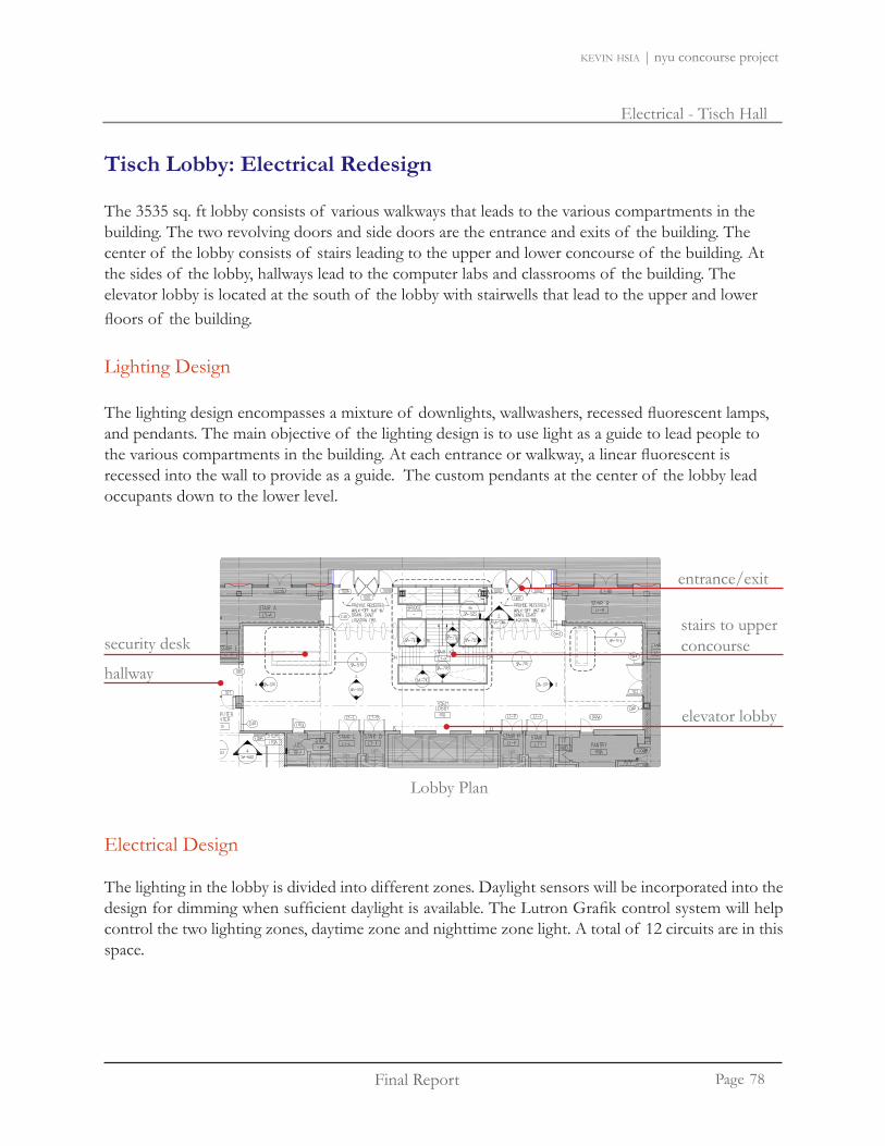
Final Report
Electrical - Tisch Hall
kevin hsia | nyu concourse project
Page
Tisch Lobby: Electrical Redesign
The 3535 sq. ft lobby consists of various walkways that leads to the various compartments in the building. The two revolving doors and side doors are the entrance and exits of the building. The center of the lobby consists of stairs leading to the upper and lower concourse of the building. At the sides of the lobby, hallways lead to the computer labs and classrooms of the building. The elevator lobby is located at the south of the lobby with stairwells that lead to the upper and lower floors of the building.
Lighting Design
The lighting design encompasses a mixture of downlights, wallwashers, recessed fluorescent lamps, and pendants. The main objective of the lighting design is to use light as a guide to lead people to the various compartments in the building. At each entrance or walkway, a linear fluorescent is recessed into the wall to provide as a guide. The custom pendants at the center of the lobby lead occupants down to the lower level.
entrance/exit
security desk
elevator lobby
stairs to upper concourse
hallway
Lobby Plan
Electrical Design
The lighting in the lobby is divided into different zones. Daylight sensors will be incorporated into the design for dimming when sufficient daylight is available. The Lutron Grafik control system will help control the two lighting zones, daytime zone and nighttime zone light. A total of 12 circuits are in this space.
78
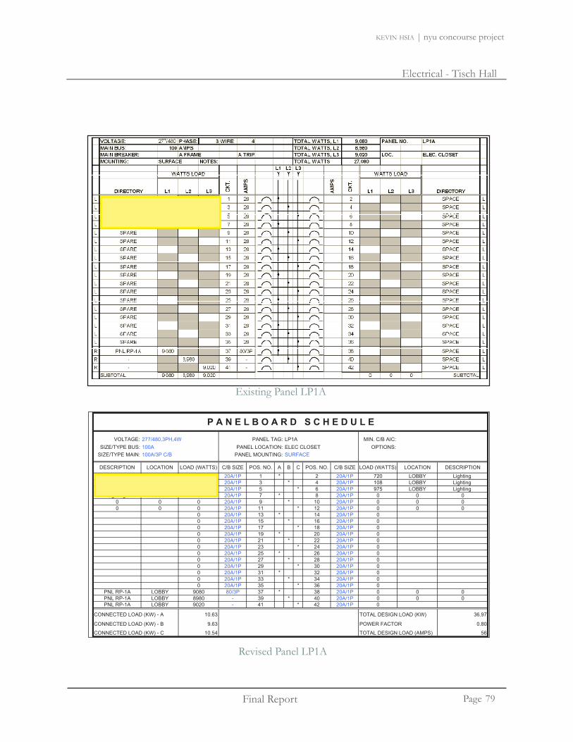
Electrical - Tisch Hall
Final Report
Electrical - Tisch Hall
kevin hsia | nyu concourse project
Page
VOLTAGE: MIN. C/B AIC: SIZE/TYPE BUS: OPTIONS:
SIZE/TYPE MAIN:
DESCRIPTION LOCATION LOAD (WATTS) C/B SIZE POS. NO. A B C POS. NO. C/B SIZE LOAD (WATTS) LOCATION DESCRIPTION
Lighting LOBBY 648 20A/1P 1 * 2 20A/1P 720 LOBBY Lighting Lighting LOBBY 546 20A/1P 3 * 4 20A/1P 108 LOBBY Lighting Lighting LOBBY 546 20A/1P 5 * 6 20A/1P 975 LOBBY Lighting Lighting LOBBY 184 20A/1P 7 * 8 20A/1P 0 0 0
0 0 0 20A/1P 9 * 10 20A/1P 0 0 00 0 0 20A/1P 11 * 12 20A/1P 0 0 0 0 20A/1P 13 * 14 20A/1P 0 0 20A/1P 15 * 16 20A/1P 0 0 20A/1P 17 * 18 20A/1P 0 0 20A/1P 19 * 20 20A/1P 0 0 20A/1P 21 * 22 20A/1P 0 0 20A/1P 23 * 24 20A/1P 0 0 20A/1P 25 * 26 20A/1P 0 0 20A/1P 27 * 28 20A/1P 0 0 20A/1P 29 * 30 20A/1P 0 0 20A/1P 31 * 32 20A/1P 0 0 20A/1P 33 * 34 20A/1P 0 0 20A/1P 35 * 36 20A/1P 0
PNL RP-1A LOBBY 9080 80/3P 37 * 38 20A/1P 0 0 0PNL RP-1A LOBBY 8980 - 39 * 40 20A/1P 0 0 0PNL RP-1A LOBBY 9020 - 41 * 42 20A/1P 0
CONNECTED LOAD (KW) - A 10.63 TOTAL DESIGN LOAD (KW) 36.97
CONNECTED LOAD (KW) - B 9.63 POWER FACTOR 0.80
CONNECTED LOAD (KW) - C 10.54 TOTAL DESIGN LOAD (AMPS) 56
277/480,3PH,4W100A100A/3P C/B
PANEL TAG:PANEL LOCATION:
LP1AELEC CLOSET
PANEL MOUNTING:
P A N E L B O A R D S C H E D U L E
SURFACE
Existing Panel LP1A
Revised Panel LP1A
79

Final Report
Electrical - Tisch Hall
kevin hsia | nyu concourse project
Page
LP1A277 3480 4
Pos Ph. Load Type Cat. Location Load Units I. PF Watts VA1 A Lighting 3 LOBBY 648 w 648 8102 A Lighting 3 LOBBY 720 w 720 9003 B Lighting 3 LOBBY 546 w 546 6834 B Lighting 3 LOBBY 108 w 108 1355 C Lighting 3 LOBBY 546 w 546 6836 C Lighting 3 LOBBY 975 w 975 12197 A Lighting 3 LOBBY 184 w 184 2308 A w 0 09 B w 0 0
10 B w 0 011 C w 0 012 C w 0 013 A 0 w 0 014 A 0 w 0 015 B 0 w 0 016 B 0 w 0 017 C 0 w 0 018 C 0 w 0 019 A 0 w 0 020 A 0 w 0 021 B 0 w 0 022 B 0 w 0 023 C 0 w 0 024 C 0 w 0 025 A 0 w 0 026 A 0 w 0 027 B 0 w 0 028 B 0 w 0 029 C 0 w 0 030 C 0 w 0 031 A 0 w 0 032 A 0 w 0 033 B 0 w 0 034 B 0 w 0 035 C 0 w 0 036 C 0 w 0 037 A PNL RP-1A 9 LOBBY 9080 w 9080 1135038 A w 0 039 B PNL RP-1A 9 LOBBY 8980 w 8980 1122540 B w 0 041 C PNL RP-1A 9 LOBBY 9020 w 9020 1127542 C 0 w 0 0
30.8 38.5 Amps= 46.3
kW kVA % AmpsA 10.6 13.3 37% 48.0B 9.6 12.0 33% 43.5C 10.5 10.9 30% 39.4
Ver. 1.03
kW kVA DF kW kVA PF1 0.0 0.0 0.70 0.0 0.0 2 0.0 0.0 0.90 0.0 0.0 3 3.7 4.7 1.00 3.7 4.7 0.804 0.0 0.0 1.00 0.0 0.0 5 0.0 0.0 1.00 0.0 0.0 6 0.0 0.0 0.80 0.0 0.0 7 0.0 0.0 1.25 0.0 0.0 8 0.0 0.0 0.80 0.0 0.0 9 27.1 33.9 1.00 27.1 33.9 0.80
30.8 38.5 20% 6.2 7.7
37.0 46.2 0.80 Amps= 55.6
0.801.00
Spare CapacityTotal Design Loads
LOAD CATAGORIES
HID lighting
receptaclescomputers
kitchen equipment
Total Demand Loadsunassigned
PANEL TOTAL
HVAC fansheating
Connected Demand
PHASE TOTAL
PHASE LOADING
PANELBOARD SIZING WORKSHEETPanel Tag-------------------------->
Nominal Phase to Neutral Voltage------->Nominal Phase to Phase Voltage-------->
Phase:Wires:
Panel Location: ELEC CLOSET
fluorescent lighting
incandescent lighting
PHASE TOTAL
PHASE TOTAL
Remarks
Default Power Factor =Default Demand Factor =
Electrical Panel
80

Electrical - Tisch Hall
Final Report
Electrical - Tisch Hall
kevin hsia | nyu concourse project
Page
Lobby - Different Control Modes
Power Plan
Dimming will be determined by the daylight sensor.
Daytime Mode
Nighttime Mode
For the daytime mode, lights will be dimmed to save power and use daylight to provide illumination to the space.
For the nighttime mode, all of the lights will be on
Power Plan
All lighting will be on.
81

Final Report
Electrical - Tisch Hall
kevin hsia | nyu concourse project
Page
Lutron Controls
ZONE FIXTURE TYPE Voltage SOURCE CIRCUIT NO. LOAD VA CONTROL1 L13,L18 277 NORMAL EXT 1 -1 216 GRAFIK 30002 L17 277 NORMAL EXT 1 -2 180 GRAFIK 30003 L16 277 NORMAL EXT 1 -3 180 GRAFIK 30004 L14 277 NORMAL EXT 1 -4 180 GRAFIK 30005 L15,L17 277 NORMAL EXT 1 -5 216 GRAFIK 30006 L16 277 NORMAL EXT 1 -6 252 GRAFIK 30007 L12 277 NORMAL EXT 1 -7 184 GRAFIK 30008 L12, L11 277 NORMAL EXT 1 -8 546 GRAFIK 30009 L9, L10 277 NORMAL EXT 1 -9 546 GRAFIK 3000
LUTRON DIMMING CONTROL PANEL 2 LOCATION: LEVEL 1
82

Electrical - Tisch Hall
Final Report
Electrical - Tisch Hall
kevin hsia | nyu concourse project
Page
Lobby Circuiting
*Larger lighting plan can be found in Appendix I : E201
Eletrical Plan
Feeder Sizing
Design Load: 48.4A Design Load with 20% spare: 58AFeeder Protection Device: 60A Wire Size: (4)#4 2 1/2”, CU THW
83

Final Report
Electrical - Classroom
kevin hsia | nyu concourse project
Page
Classroom: Electrical Redesign
The 1324 sq. ft classroom has a seating capacity of 73 occupants. The classroom is divided into five tiers. At the front of the room, there are three white boards, with the side white boards have a sliding component which can be adjusted into a projection screen. The ceiling are 2’x2’ armstrong panels. The materials in the classroom are dry wall with an eggshell finish to it.
Lighting Design
The lighting design encompasses a mixture of downlights, wallwashers, and wall sconces. The main objective of the lighting design is to provide sufficient light levels on the reading/writing surface of the student desks as well as the white boards at the front of the classroom. At the same time, the wall sconces will provide visual interest on the side walls of the classroom.
projection screens and white boards
closet
lecture tables/desk
Classroom Plan
exit
Electrical Design
The lighting in the classroom is divided into different zones. The control is based on the Lutron 3000 Grafik control system. A total of two lighting zones will be designed for the classroom: presentation and general lecture mode. There will be a total of 6 circuits in the room.
84

Electrical - Classroom
Final Report
Electrical - Classroom
kevin hsia | nyu concourse project
Page
VOLTAGE: MIN. C/B AIC: SIZE/TYPE BUS: OPTIONS:
SIZE/TYPE MAIN:
DESCRIPTION LOCATION LOAD (WATTS) C/B SIZE POS. NO. A B C POS. NO. C/B SIZE LOAD (WATTS) LOCATION DESCRIPTION
Lighting UC18 180 20A/1P 1 * 2 20A/1P 180 UC18 LightingLighting UC18 612 20A/1P 3 * 4 20A/1P 273 UC18 LightingLighting UC18 669 20A/1P 5 * 6 20A/1P 1800 UC14 LightingLighting UC15 1300 20A/1P 7 * 8 20A/1P 1400 UC17 Lighting
Low volt light controlLVPUC-R1,2,3,5 1700 20A/1P 9 * 10 20A/1P 1160 LVPUC-R4,6,7,8 Low volt light controlLow volt light control LVPUC-R9,10 1160 20A/1P 11 * 12 20A/1P 950 LVPUC-R11,12 Low volt light control
Lighting TOILET 1050 20A/1P 13 * 14 20A/1P 1400 PUC-R13,14,15,16Low volt light controlLow volt light control LVPUC-R18,19 600 20A/1P 15 * 16 20A/1P 0
0 20A/1P 17 * 18 20A/1P 0 0 20A/1P 19 * 20 20A/1P 0 0 20A/1P 21 * 22 20A/1P 0 0 20A/1P 23 * 24 20A/1P 0 0 20A/1P 25 * 26 20A/1P 0 0 20A/1P 27 * 28 20A/1P 0 0 20A/1P 29 * 30 20A/1P 0 0 20A/1P 31 * 32 20A/1P 0 0 20A/1P 33 * 34 20A/1P 0 0 20A/1P 35 * 36 20A/1P 00 0 0 20A/1P 37 * 38 20A/1P 0 0 00 0 0 20A/1P 39 * 40 20A/1P 0 0 00 0 0 20A/1P 41 * 42 20A/1P 0
CONNECTED LOAD (KW) - A 5.51 TOTAL DESIGN LOAD (KW) 17.32
CONNECTED LOAD (KW) - B 4.35 POWER FACTOR 0.80
CONNECTED LOAD (KW) - C 4.58 TOTAL DESIGN LOAD (AMPS) 26
P A N E L B O A R D S C H E D U L E
FOR PANELBOARD 1L1BSURFACE
10KPROVIDE FEED THROUGH LUGS
277/480,3PH,4W100A100A/3P C/B
PANEL TAG:PANEL LOCATION:
LP4-UC1AELEC CLOSET UC19
PANEL MOUNTING:
Existing Panel LP4-UC1A
Revised Panel LP4-UC1A
PANEL SCHEDULEVOLTAGE 277/480 3PH, 4W TAG TYPE PANELMOUNTING SURFACE LP4-UC1A C/B MIN AIC FEEDSIZE/TYPE BUS 100 AMPS LOCATION OPTIONS/ACCESSRSSIZE/TYPE MAINS A FRAME REMARKS
LOAD LOCATION LOAD C/B POS A B C POS C/B LOAD LOCATION LOADDESCRIPTION WATTS SIZE NO PH PH PH NO SIZE WATTS DESCRIPTION
Lighting UC14- LTG 1800 20A 1 * 2 20A 1700 0 LVPUC - R1 2 3 5 Low voltage lighting control
ELEC. CLOSET UC19
Lighting UC14- LTG 1800 20A 1 2 20A 1700.0 LVPUC - R1,2,3,5 Low voltage lighting controlLighting UC15- LTG 1300 20A 3 * 4 20A 1160.0 LVPUC - R4,6,7,8 Low voltage lighting controlLighting UC17- LTG 1400 20A 5 * 6 20A 1160.0 LVPUC - R9, 10 Low voltage lighting controlLighting UC18- LTG 2100 20A 7 * 8 20A 950.0 LVPUC - R11,12 Low voltage lighting control
9 * 10 20A 1050.0 LTG TOILET/CP CENTER Lighting11 * 12 20A 1400.0 LVPUC-R13,14,15,16,17 Low voltage lighting control13 * 14 20A 600.0 LVPUC - R18,19 Low voltage lighting control15 * 1617 * 1819 * 2021 * 2223 * 2425 * 2627 * 2829 * 3031 * 3231 * 3233 * 3435 * 3637 * 3839 * 4041 * 42
SUB-TOTAL A PHASE 7150.0 B PHASE 3510.0 C PHASE 3960.0TOTAL CONNECTED LOAD (WATTS) 14620.0 DEMAND LOAD 13158.0
85

Final Report
Electrical - Classroom
kevin hsia | nyu concourse project
Page
LP4-UC1A277 3480 4
Pos Ph. Load Type Cat. Location Load Units I. PF Watts VA1 A Lighting 3 UC18 180 w 180 2252 A Lighting 3 UC18 180 w 180 2253 B Lighting 3 UC18 612 w 612 7654 B Lighting 3 UC18 273 w 273 3415 C Lighting 3 UC18 669 w 669 8366 C Lighting 3 UC14 1800 w 1800 22507 A Lighting 3 UC15 1300 w 1300 16258 A Lighting 3 UC17 1400 w 1400 17509 B Low volt light control 9 VPUC-R1,2,3 1700 w 1700 2125
10 B Low volt light control 9 VPUC-R4,6,7 1160 w 1160 145011 C Low volt light control 9 LVPUC-R9,10 1160 w 1160 145012 C Low volt light control 9 VPUC-R11,1 950 w 950 118813 A Lighting 3 TOILET 1050 w 1050 131314 A Low volt light control 9 C-R13,14,15 1400 w 1400 175015 B Low volt light control 9 VPUC-R18,1 600 w 600 75016 B 0 w 0 017 C 0 w 0 018 C 0 w 0 019 A 0 w 0 020 A 0 w 0 021 B 0 w 0 022 B 0 w 0 023 C 0 w 0 024 C 0 w 0 025 A 0 w 0 026 A 0 w 0 027 B 0 w 0 028 B 0 w 0 029 C 0 w 0 030 C 0 w 0 031 A 0 w 0 032 A 0 w 0 033 B 0 w 0 034 B 0 w 0 035 C 0 w 0 036 C 0 w 0 037 A w 0 038 A w 0 039 B w 0 040 B w 0 041 C w 0 042 C 0 w 0 0
14.4 18.0 Amps= 21.7
kW kVA % AmpsA 5.5 6.9 38% 24.9B 4.3 5.4 30% 19.6C 4.6 5.7 32% 20.7
Ver. 1.03
kW kVA DF kW kVA PF1 0.0 0.0 0.70 0.0 0.0 2 0.0 0.0 0.90 0.0 0.0 3 7.5 9.3 1.00 7.5 9.3 0.804 0.0 0.0 1.00 0.0 0.0 5 0.0 0.0 1.00 0.0 0.0 6 0.0 0.0 0.80 0.0 0.0 7 0.0 0.0 1.25 0.0 0.0 8 0.0 0.0 0.80 0.0 0.0 9 7.0 8.7 1.00 7.0 8.7 0.80
14.4 18.0 20% 2.9 3.6
17.3 21.7 0.80 Amps= 26.1
0.801.00
Default Power Factor =Default Demand Factor =
Remarks
fluorescent lighting
incandescent lighting
PHASE TOTAL
PHASE TOTAL
PANELBOARD SIZING WORKSHEETPanel Tag-------------------------->
Nominal Phase to Neutral Voltage------->Nominal Phase to Phase Voltage-------->
Phase:Wires:
Panel Location: ELEC CLOSET UC19
Total Demand Loadsunassigned
PANEL TOTAL
HVAC fansheating
Connected Demand
PHASE TOTAL
PHASE LOADING
Spare CapacityTotal Design Loads
LOAD CATAGORIES
HID lighting
receptaclescomputers
kitchen equipment
Electrical Panel
86

Electrical - Classroom
Final Report
Electrical - Classroom
kevin hsia | nyu concourse project
Page
Classroom - Different Control Modes
reflected ceiling plan
plan not to scale
20% Dimming
50% Dimming
70% Dimming
reflected ceiling plan
No Dimming for anyof the luminaires in the space.
plan not to scaleGeneral mode
Presentation Mode
For the general mode, all of the lighting in the room will be turned on.
For the presentation mode, the first row of downlights will dim to 20%, followed by the second row of downlights dim to 50%, and the rest of the downlights at 70%. The wall washers and wall sconces will be turned off.
87

Final Report
Electrical - Classroom
kevin hsia | nyu concourse project
Page
Lutron Light Control
ZONE FIXTURE TYPE Voltage SOURCE CIRCUIT NO. LOAD VA CONTROL1 L1A 277 NORMAL LP4-UC1A-1 180 GRAFIK 30002 L1A 277 NORMAL LP4-UC1A-2 180 GRAFIK 30003 L1A, L2B 277 NORMAL LP4-UC1A-3 612 GRAFIK 30004 L2A 277 NORMAL LP4-UC1A-4 273 GRAFIK 30005 L3 277 NORMAL LP4-UC1A-5 669 GRAFIK 3000
LUTRON DIMMING CONTROL PANEL 1 LOCATION: LEVEL 1
88

Electrical - Classroom
Final Report
Electrical - Classroom
kevin hsia | nyu concourse project
Page
Classroom Circuiting
*Larger lighting plan can be found in Appendix I : E301
Electrical Plan
Feeder Sizing
Design Load: 118A Design Load with 20% spare: 142AFeeder Protection Device: 150A Wire Size: (4)#1/02” CU THW
89

Final Report
Electrical - MBA Student Lounge
kevin hsia | nyu concourse project
Page
Background InformationThe MBA student lounge is located in the upper concourse of Tisch Hall. The student lounge is used as a place for students to do work and relax. The 2,100 sq.ft space is divided into four sections, a pantry in the back, computer counter and lounge area, tables area, and another lounge area in the front.
Lighting DesignThe lighting consist a combination of wallwashers, recessed fluorescents, LEDs, and surface mount luminaires. The objective of the lighting design is to provide a relaxing and pleasant atmosphere for students to enjoy.
MBA Student Lounge: Electrical Redesign
Electrical DesignThe electrical design involves dividing up the lighting into 5 zones with 5 switches. The lounge does not need any dimming. A total of 5 circuits will be designed for this space.
central table
computer area
MBA Student Lounge
lounge area
pantry
*Larger lighting plan can be found in Appendix I : E401
90

Final Report
Electrical - MBA Student Lounge
kevin hsia | nyu concourse project
Page
VOLTAGE: MIN. C/B AIC: SIZE/TYPE BUS: OPTIONS:
SIZE/TYPE MAIN:
DESCRIPTION LOCATION LOAD (WATTS) C/B SIZE POS. NO. A B C POS. NO. C/B SIZE LOAD (WATTS) LOCATION DESCRIPTION
Furniture Feed UC31 1000 20A/1P 43 * 44 20A/1P 1000 UC31 Furniture FeedFurniture Feed UC31 1000 20A/1P 45 * 46 20A/1P 1000 UC31 Furniture FeedFurniture Feed UC31 1000 20A/1P 47 * 48 20A/1P 1000 UC31 Furniture FeedFurniture Feed UC31 1000 20A/1P 49 * 50 20A/1P 1000 UC31 Furniture FeedFurniture Feed UC31 1000 20A/1P 51 * 52 20A/1P 1000 UC31 Furniture FeedFurniture Feed UC31 1000 20A/1P 53 * 54 20A/1P 1000 UC31 Furniture Feed
WAP Rec UC31 200 20A/1P 55 * 56 20A/1P 0 0 0WAP Rec UC31 200 20A/1P 57 * 58 20A/1P 0 0 0WAP Rec UC31 200 20A/1P 59 * 60 20A/1P 0
0 20A/1P 61 * 62 20A/1P 0 0 20A/1P 63 * 64 20A/1P 0
Lighting UC31 248 20A/1P 65 * 66 20A/1P 0Lighting UC31 144 20A/1P 67 * 68 20A/1P 502 UC31 LightingLighting UC31 1031 20A/1P 79 * 70 20A/1P 253 UC31 Lighting
0 20A/1P 71 * 72 20A/1P 0 0 20A/1P 73 * 74 20A/1P 0 0 20A/1P 75 * 76 20A/1P 0 0 20A/1P 77 * 78 20A/1P 00 0 0 80/3P 79 * 80 20A/1P 0 0 00 0 0 - 81 * 82 20A/1P 0 0 00 0 0 - 83 * 84 20A/1P 0 0
CONNECTED LOAD (KW) - A 4.85 TOTAL DESIGN LOAD (KW) 17.73
CONNECTED LOAD (KW) - B 5.48 POWER FACTOR 0.80
CONNECTED LOAD (KW) - C 4.45 TOTAL DESIGN LOAD (AMPS) 62
P A N E L B O A R D S C H E D U L E
SURFACE
120/208,3PH,4W100A100A/3P C/B
PANEL TAG:PANEL LOCATION:
RPSA SEC. 2ELEC CLOSET
PANEL MOUNTING:
Existing Panel RPSA (includes revised Lobby lighting)
Revised Panel RPSA
91

Final Report
Electrical - MBA Student Lounge
kevin hsia | nyu concourse project
Page
RPSA120 3208 4
Pos Ph. Load Type Cat. Location Load Units I. PF Watts VA43 A Furniture Feed 9 UC31 1000 w 1000 125044 A Furniture Feed 9 UC31 1000 w 1000 125045 B Furniture Feed 9 UC31 1000 w 1000 125046 B Furniture Feed 9 UC31 1000 w 1000 125047 C Furniture Feed 9 UC31 1000 w 1000 125048 C Furniture Feed 9 UC31 1000 w 1000 125049 A Furniture Feed 9 UC31 1000 w 1000 125050 A Furniture Feed 9 UC31 1000 w 1000 125051 B Furniture Feed 9 UC31 1000 w 1000 125052 B Furniture Feed 9 UC31 1000 w 1000 125053 C Furniture Feed 9 UC31 1000 w 1000 125054 C Furniture Feed 9 UC31 1000 w 1000 125055 A WAP Rec 9 UC31 200 w 200 25056 A w 0 057 B WAP Rec 9 UC31 200 w 200 25058 B w 0 059 C WAP Rec 9 UC31 200 w 200 25060 C 0 w 0 061 A 0 w 0 062 A 0 w 0 063 B 0 w 0 064 B 0 w 0 065 C Lighting 3 UC31 248 w 248 31066 C 0 w 0 067 A Lighting 3 UC31 144 w 144 18068 A Lighting 3 UC31 502 w 502 62869 B Lighting 3 UC31 1031 w 1031 128970 B Lighting 3 UC31 253 w 253 31671 C 0 w 0 072 C 0 w 0 073 A 0 w 0 074 A 0 w 0 075 B 0 w 0 076 B 0 w 0 077 C 0 w 0 078 C 0 w 0 079 A w 0 080 A w 0 081 B w 0 082 B w 0 083 C w 0 084 C 0 w 0 0
14.8 18.5 Amps= 51.3
kW kVA % AmpsA 4.8 6.1 33% 50.5B 5.5 6.9 37% 57.1C 4.4 5.6 30% 46.3
Ver. 1.03
kW kVA DF kW kVA PF1 0.0 0.0 0.70 0.0 0.0 2 0.0 0.0 0.90 0.0 0.0 3 2.2 2.7 1.00 2.2 2.7 0.804 0.0 0.0 1.00 0.0 0.0 5 0.0 0.0 1.00 0.0 0.0 6 0.0 0.0 0.80 0.0 0.0 7 0.0 0.0 1.25 0.0 0.0 8 0.0 0.0 0.80 0.0 0.0 9 12.6 15.8 1.00 12.6 15.8 0.80
14.8 18.5 20% 3.0 3.7
17.7 22.2 0.80 Amps= 61.6
0.801.00
Default Power Factor =Default Demand Factor =
Remarks
fluorescent lighting
incandescent lighting
PHASE TOTAL
PHASE TOTAL
PANELBOARD SIZING WORKSHEETPanel Tag-------------------------->
Nominal Phase to Neutral Voltage------->Nominal Phase to Phase Voltage-------->
Phase:Wires:
Panel Location: ELEC CLOSET
Total Demand Loadsunassigned
PANEL TOTAL
HVAC fansheating
Connected Demand
PHASE TOTAL
PHASE LOADING
Spare CapacityTotal Design Loads
LOAD CATAGORIES
HID lighting
receptaclescomputers
kitchen equipment
92

Final Report
Electrical - MBA Student Lounge
kevin hsia | nyu concourse project
Page
MBA Lounge Circuiting
*Larger lighting plan can be found in Appendix : E401
Electrical Plan
Feeder Sizing
Design Load: 48.4A Design Load with 20% spare: 58AFeeder Protection Device: 60A Wire Size: (4)#4 - 2 1/2” CU THWN
93

Final Report
Electrical Breadth- Backup Generator
kevin hsia | nyu concourse project
Page
Backup Generator Design: Electrical Breadth
The current electrical system of Tisch Hall does not contain a backup generator. The current emergency generator is located in another building. Electrical Depth 1 proposes the installation of a backup generator that will supply power to the Ground, Upper, and Lower Concourse of Tisch Hall. The backup generator will need to supply power to the emergency lighting system, elevator shaft, security, and fire alarm system. Electrical depth 1 will involve picking out a backup generator to supply adequate emergency power to Tisch Hall. The study also involves finding a location for the backup generator to be placed.
Emergency Loads
33832 W33.83 kW
Design with 20% Spare 40.60 kW
Type L UC LC Sum Lamp Description Watt Total WattL38 12 12 37MR16/IR/NFL/C 87 1044L27 6 6 37MR16/IR/NFL/CFPC40/830 46 276L47 2 2 CF32DT/E/IN/830 36 72L1B 2 12 8 22 (2) FP21/830/ECO 48 1056L24K 42 42 FP28/830/ECO 32 1344L24L 12 12 FP28/830/ECO 32 384L24 29 29 FP28/830/ECO 32 928L24C 10 10 FP28/830/ECO 32 320L16 11 11 CF26DT/E/IN/830 29 319L25 16 6 22 FP28/830/ECO 33 726L4 5 5 CF32DT/E/IN/830 36 180L31 6 6 CF32DT/E/IN/830 36 216L6B 1 1 CF26DT/E/IN/830 29 29L6A 5 8 13 CF26DT/E/IN/830 29 377L6 2 2 CF26DT/E/IN/830 29 58L9C 14 14 MP50/C/U/MED 58 812L23B 6 6 CDM70/PAR38/FL/3K/ 78 468
Overall Emergency Load
Load
Emergency Lighting Load
L23B 6 6 CDM70/PAR38/FL/3K/ 78 468L50 4 4 FP28/830/ECO 33 132L12A 2 2 CMH39PAR20/FL 45 90L28 12 12 CF32DT/E/IN/830 46 552L28C 1 1 CF32DT/E/IN/830 46 46L28A 8 8 CF32DT/E/IN/830 46 368L46 3 3 CMH39/UPAR20/FL25 23 69L15 12 12 FP28/830/ECO 33 396
Total 10262
Total Watt223702001000
Total 23570
30 hp elevatorFire Alarm System
Security
Other LoadsType
Traction ElevatorDescription
94

Final Report
Electrical Breadth- Backup Generator
kevin hsia | nyu concourse project
Page
Emergency Panelboard Schedule
VOLTAGE: MIN. C/B AIC: SIZE/TYPE BUS: OPTIONS:
SIZE/TYPE MAIN:
DESCRIPTION LOCATION LOAD (WATTS) C/B SIZE POS. NO. A B C POS. NO. C/B SIZE LOAD (WATTS) LOCATION DESCRIPTION
Lighting UC 2868 20A/1P 1 * 2 20A/1P 1000 All Level SecurityLighting LC 3634 20A/1P 3 * 4 20A/1P 200 All Level Fire Alarm SystemLighting UC 2606 20A/1P 5 * 6 20A/1P 1598 Level 1 LightingElevator All Level 7457 20A/1P 7 * 8 20A/1P 0 0 0Elevator All Level 7457 20A/1P 9 * 10 20A/1P 0 0 0Elevator All Level 7457 20A/1P 11 * 12 20A/1P 0 0 0
0 0 0 20A/1P 13 * 14 20A/1P 0 0 00 0 0 20A/1P 15 * 16 20A/1P 0 00 0 20A/1P 17 * 18 20A/1P 0 0 20A/1P 19 * 20 20A/1P 0 0 20A/1P 21 * 22 20A/1P 0 0 20A/1P 23 * 24 20A/1P 0 0 20A/1P 25 * 26 20A/1P 0 0 20A/1P 27 * 28 20A/1P 0 0 20A/1P 29 * 30 20A/1P 0 0 20A/1P 31 * 32 20A/1P 0 0 20A/1P 33 * 34 20A/1P 0 0 20A/1P 35 * 36 20A/1P 0 0 20A/1P 37 * 38 20A/1P 0 0 20A/1P 39 * 40 20A/1P 0 0 20A/1P 41 * 42 20A/1P 0
CONNECTED LOAD (KW) - A 11.33 TOTAL DESIGN LOAD (KW) 41.13
CONNECTED LOAD (KW) - B 11.29 POWER FACTOR 0.05
CONNECTED LOAD (KW) - C 11.66 TOTAL DESIGN LOAD (AMPS) 977
EMR-1ELEC CLOSET UC19
PANEL MOUNTING: FOR PANELBOARD 1L1BSURFACE
PANEL TAG:PANEL LOCATION:
1000A/3P C/B
10KPROVIDE FEED THROUGH LUGS
P A N E L B O A R D S C H E D U L E277/480 ,3PH,4W1000A
95

Final Report
Electrical Breadth- Backup Generator
kevin hsia | nyu concourse project
Page
Emergency Panelboard
EMR-1277 3480 4
Pos Ph. Load Type Cat. Location Load Units I. PF Watts VA1 A Lighting 3 UC 2868 w 0.95 2868 30192 A Security 9 All Level 1000 w 1.00 1000 10003 B Lighting 3 LC 3634 w 0.95 3634 38254 B Fire Alarm System 9 All Level 200 w 1.00 200 2005 C Lighting 3 UC 2606 w 0.95 2606 27436 C Lighting 3 Level 1 1598 w 0.95 1598 16827 A Elevator 9 All Level 7457 w 1.00 7457 74578 A 0 w 0 09 B Elevator 9 All Level 7457 w 1.00 7457 7457
10 B 0 w 0 011 C Elevator 9 All Level 7457 w 1.00 7457 745712 C 0 w 0 013 A 0 w 0 014 A 0 w 0 015 B 0 w 0 016 B 0 w 0 017 C 0 w 0 018 C 0 w 0 019 A 0 w 0 020 A 0 w 0 021 B 0 w 0 022 B 0 w 0 023 C 0 w 0 024 C 0 w 0 025 A 0 w 0 026 A 0 w 0 027 B 0 w 0 0
PANELBOARD SIZING WORKSHEETPanel Tag-------------------------->
Nominal Phase to Neutral Voltage------->Nominal Phase to Phase Voltage-------->
Phase:Wires:
Panel Location: ELEC CLOSET UC19
Remarks
28 B 0 w 0 029 C 0 w 0 030 C 0 w 0 031 A 0 w 0 032 A 0 w 0 033 B 0 w 0 034 B 0 w 0 035 C 0 w 0 036 C 0 w 0 037 A 0 w 0 038 A 0 w 0 039 B 0 w 0 040 B 0 w 0 041 C 0 w 0 042 C 0 w 0 0
34.3 34.8 Amps= 41.9
kW kVA % AmpsA 11.3 11.5 33% 41.4B 11.3 11.5 33% 41.5C 11.7 11.9 34% 42.9
Ver. 1.02
kW kVA DF kW kVA PF1 0.0 0.0 0.70 0.0 0.0 2 0.0 0.0 0.90 0.0 0.0 3 10.7 11.3 1.00 10.7 120.7 0.094 0.0 0.0 1.00 0.0 0.0 5 0.0 0.0 1.00 0.0 0.0 6 0.0 0.0 0.80 0.0 0.0 7 0.0 0.0 1.25 0.0 0.0 8 0.0 0.0 0.80 0.0 0.0 9 23.6 23.6 1.00 23.6 555.6 0.04
34.3 676.2 20% 6.9 135.2
41.1 811.5 0.05 Amps= 976.5Spare Capacity
Total Design Loads
LOAD CATAGORIES
HID lighting
receptaclescomputers
kitchen equipment
incandescent lighting
Total Demand Loadsunassigned
PANEL TOTAL
HVAC fansheating
Connected
fluorescent lighting
Demand
PHASE TOTAL
PHASE LOADINGPHASE TOTAL
PHASE TOTAL
41.1 811.5 0.05 Amps= 976.5
0.801.00
Total Design Loads
Default Power Factor =Default Demand Factor =
96

Final Report
Electrical Breadth- Backup Generator
kevin hsia | nyu concourse project
Page
Proposal Site for Backup Generator
The existing space in Tisch Hall has no room for a backup generator and a fuel tank to be placed. A proposal to create an electrical room next to the men’s room in the upper concourse would be an ideal location. The electrical room would hold both the backup generator and fuel tank. A fuel pipe line would then link the fuel tank to an outdoor fuel station at the corner of West 3rd Street and Mercer Street. If fuel is needed, fuel truck can make a stop to fuel up the tank.
The electrical room would be located between columns H and J which should provide sufficient space needed. There is no proposal to erect new columns or beams to support the room since there is already an existing structural system in place.
97
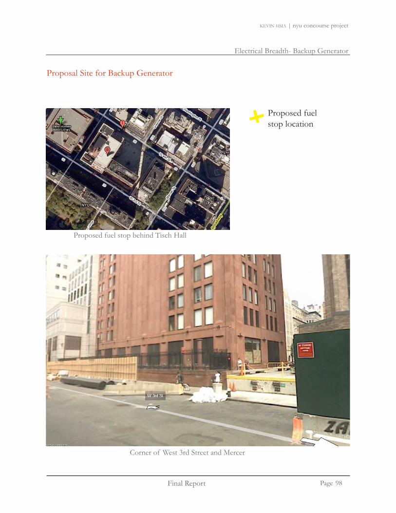
Final Report
Electrical Breadth- Backup Generator
kevin hsia | nyu concourse project
Page
Proposal Site for Backup Generator
Proposed fuel stop location
Corner of West 3rd Street and Mercer
Proposed fuel stop behind Tisch Hall
98

Final Report
Electrical Breadth- Backup Generator
kevin hsia | nyu concourse project
Page
Proposal Site for Backup Generator
The backup generator supplies power when the building power system turns off. The emergency panel sends signals to the automatic transfer switch to utilize the backup generator.
The emergency panel will be in the new electrical room. The automatic transfer switch will be located in elec-trical closet UC04.
Proposed Electrical Room
Proposed Generator System
Generator: 4BT3.3 Series Engine - DGHE
Transfer Switch: Transfer Switch OTEC Open
Fuel Tank Enclosures and Tanks 230-500W
*Information on generator can be found in Appendix E.
99
Final Report
Electrical Breadth- PV Analysis
kevin hsia | nyu concourse project
Page
Photovoltaic Analysis: Electrical Breadth
New York City is one of the largest cities in the world. The city is a big consumer of electricity compared to many cities. In recent years, New York City has focused on reducing the environmental impact. A study conducted in 2004 estimated that by 2008, New York City would need an extra 3,780 MW of electricity. The city is promoting new initiatives with energy efficient systems to provide elec-tricity and enhance the quality of life for residents in New York City.
In the 2004 New York City Energy Policy prepared by the New York City Energy Policy Task Force, the city encourages various methods of energy efficiency to increase electricity resources. Renewable energy technologies such as solar photovoltaic panels are encouraged to increase the diversity of energy sources away from heavy reliance on fossil fuels.
The New York University Concourse Project involves the renovation of the business campus. This electrical breadth study will explore the possibility for NYU to install photovoltaic panels to see if it is economical and beneficial. The study will look at potential places to mount photovoltaic panels. Also, a model of the NYU campus and surrounding buildings will be constructed to see if any of the sur-rounding buildings will block any sunlight on the rooftop of the NYU building. Last, the analysis will look at the financial benefits of installing photovoltaic panels.
100

Final Report
Electrical Breadth- PV Analysis
kevin hsia | nyu concourse project
Page
PV array mounting positions
Kaufman Center
Tisch Hall
Weaver Hall
New York University Business Campus
Areas in orange are proposed sites for installation of photovoltaic panels.
101

Final Report
Electrical Breadth- PV Analysis
kevin hsia | nyu concourse project
Page
During the equinox, the surrounding buildings does not block any sunlight on the NYU buildings.
9 AM
12 PM
3 PM
6 PM
EquinoxSeptember 21 & March 21
NYU buildings in darker gray. The NYU buildings are Weaver Hall, Tisch Hall, and Kaufman Center.
102

Final Report
Electrical Breadth- PV Analysis
kevin hsia | nyu concourse project
Page
During the summer solstice, the sun is at the highest point. The surrounding buildings does not shade the rooftop of the NYU buildings.
9 AM
12 PM
3 PM
6 PM
Summer SolsticeJune 21
NYU buildings in darker gray. The NYU buildings are Weaver Hall, Tisch Hall, and Kaufman Center.
103

Final Report
Electrical Breadth- PV Analysis
kevin hsia | nyu concourse project
Page
During the winter solstice, the sun is at the lowest point. Again, the surrounding buildings do not shade the NYU buildings.
9 AM
12 PM
3 PM
6 PM
Winter Solstice December 21
NYU buildings in darker gray. The NYU buildings are Weaver Hall, Tisch Hall, and Kaufman Center.
104

Final Report
Electrical Breadth- PV Analysis
kevin hsia | nyu concourse project
Page
Space Area (sq.ft)Weaver Hall 6256Ticsh Hall 1900Kaufman Center 19919
Total Space 2807575% of space used 21056
Photo ArrayArea per photo array 15.125 sq. ftNumber of Panels 1392Power Generated (W) 278,430
Power Generated 278 kW
PHOTO ARRAY MOUNTING SPACELocation New York CityCoordinates 40:40:11N 73:56:38W
Resource Assessment Solar Tracking Mode FixedSlope 45°Azimuth 315°
PhotovoltaicManufacture BP SolarModel bp solar SX 3200Efficiency 9%Nominal Operating Temperatu 45°CSolar Collecting Area 33293 sq. ft.Miscellaneous Losses 10%
InverterEfficiency 90%Capacity 278.4 kWmiscellaneous losses 10%
SummaryCapacity Factor 12.30%
Electricity generated 300.85 MWh
PHOTO ARRAY ANALYSIS
For this study, the BP solar SX3200 is selected to perform the calculations. The BP solar SX3200 is small and produces up to 200W of electricity per panel. The maximum power generated is 278 kW. With rooftops of Weaver Hall, Tisch Hall, and the Kaufman Center utilized, a total of 21057 sq.ft. of space can be installed with photovoltaic panels. A total of 1392 panels is proposed.
Photovoltaic System
200 watt photovoltaic module SX 3200
6802.0037 REV A 06/07©BP Solar 2007
High-efficiency photovoltaic module using silicon nitride multicrystalline silicon cells
Mechanical Characteristics
Dimensions Length: 1680mm (66.14”) Width: 837mm (32.95”) Depth: 50mm (1.97”)
Weight 15.4 kg (33.95 pounds)
Solar Cells 50 cells (156mm x 156mm) in a 5x10 matrix connected in series
Output Cables RHW-2 AWG# 12 (4mm2), cable with polarized weatherproof DC rated Multicontact connectors;
asymmetrical lengths - 1250mm (-) and 800mm (+)
Diodes IntegraBus™ technology includes Schottky by-pass diodes integrated into the printed circuit board bus
Construction Front: High-transmission 3mm (1/8th in) tempered glass; Back: White or BlackTedlar; Encapsulant: EVA
Frame B Anodized aluminium alloy type 6063T6 Universal frame; Color: bronze
Electrical Characteristics2 SX 3200 SX 3195Maximum power (Pmax)3 200W 195W
Voltage at Pmax (Vmp) 24.5V 24.4
Current at Pmax (Imp) 8.16A 7.96A
Warranted minimum Pmax 182.0W 177.5W
Short-circuit current (Isc) 8.7A 8.6A
Open-circuit voltage (Voc) 30.8V 30.7V
Temperature coefficient of Isc (0.065±0.015)%/ °C
Temperature coefficient of Voc -(111±10)mV/°C
Temperature coefficient of power -(0.5±0.05)%/°C
NOCT (Air 20°C; Sun 0.8kW/m2; wind 1m/s) 47±2°C
Maximum series fuse rating 15A
Maximum system voltage 600V (U.S. NEC rating)
PerformanceRated power (Pmax) 200WPower tolerance ±9%Nominal voltage 16VLimited Warranty1 25 years
ConfigurationB Bronze frame with output cables and polarized Multicontact
(MC) connectors
1. Module warranty: 25-year limited warranty of 80% power output; 12-year limited warranty of 90% power output; 5-year limited warranty of materialsand workmanship. See your local representative for full terms of these warranties.
2. This data represents the performance of typical SX 3200 products, and is based on measurements made in accordance with ASTM E1036 correctedto SRC (STC.)
3. During the stabilization process that occurs during the first few months of deployment, module power may decrease by up to 1% from typical Pmax.
*Numbers calculated with the RETScreen Clean Energy Project Analysis Software
105
Final Report
Electrical Breadth- PV Analysis
kevin hsia | nyu concourse project
Page
NYSERDA – PV Incentive Program
The New York State Energy Research and Development Authority provide incentives of $2-$5 per watt (DC) for installation of approved photovoltaic systems. For school, the maximum capacity sup-ported is $5/W up to a maximum of 25 kW per site meter. Incentives will only be available to eligible installers. New York University will quality for the program since Consolidated Edison Company of New York is one of the eligible utilities. Since the NYU photovoltaic panels will produce a maximum of 278 kW of power, the incentive will only cover about 10% of the cost.
Incentive Type: State Rebate Program • Eligible Renewable/Other Technologies: Photovoltaic• Applicable Status: Institutions• Incentive Amount: $2-$5/watt DC • Eligible System Size: Schools: 25 kW per site meter• Program Budget: $38.8 million (2008-2009) • Potential Incentive: $125,000•
NYSERDA – PV Incentive Program
New York State Energy Research and Development Authority (NYSERDA): Peak Load Reduction Program
The Peak Load Reduction Program aims to reduce demand for electricity during peak periods. The incentive applies for PV systems of 20 kilowatts in size or larger. The performance based incentive targets applications which can reduce energy usage. These include lighting, hvac, chiller, commercial refrigeration, and kitchen equipment and motor loads that would apply for NYU.
Incentive Type: Peak Load Reduction Program • Eligible Renewable/Other Technologies: Photovoltaic • Applicable Status: Institutions• Incentive Amount: Up to 65% of cost, depends on type of load reducing technology • Eligible System Size: PV systems 20 kilowatts in size or bigger, depend on load reducing • technology Program Budget: $37 million (through June 2008) • Potential Incentive: Depend on load reducing technology•
Grants
There are a number of economic incentive programs provided to help support photovoltaic systems. Some of these programs provide tax cut and state rebates to help pay for the photovoltaic panels.
106

Final Report
Electrical Breadth- PV Analysis
kevin hsia | nyu concourse project
Page
New York Green Building Tax Credit Program: Corporate and Personal Tax Credits
The New York State passed the green building tax credit in 2000. The green building tax credit ap-plies to owners eligible for building which meet certain ‘green standards’. These green standards include increase energy efficiency, improve air quality, and reduce environmental impacts of large commercial buildings. The photovoltaic panels installed at NYU would quality for this program since it strives to produce green energy and help reduce environmental impact.
Incentive Type: Tax Credit Reduction• Eligible Renewable/Other Technologies: Photovoltaic• Applicable Status: Institutions• Incentive Amount: Varies with project, up to maximum of $2 million • Eligible System Size: Photovoltaic Program Budget: Program expire at end of 2009•
New York City – Property Tax Abatement for Photovoltaic (PV) Equipment Expenditures
The State of New York City enacted legislation to allow property tax abatements for photovoltaic systems for cities with a population over 1 million. NYU would certainly quality for the program.
Incentive Type: Property Tax Assessment• Eligible Renewable/Other Technologies: Photovoltaic. System must be located in city with a • population of at least 1 million. Applicable Status: Institutions• Incentive Amount: Installed from August 8, 2008 to December 31, 2010: 8.75% of system •
expenditures per year for 4 years (total of 35%). Maximum incentive is $62,5000 annually. • Eligible System Size: Program expires on Dec 31, 2012•
Grants
107

Final Report
Electrical Breadth- PV Analysis
kevin hsia | nyu concourse project
Page
NYSERDA – Energy $mart New Construction Program
The Energy $mart New Construction Program promotes energy efficient and renewable-energy resource in commercial, industrial, institutional, and family buildings. This program might qualify for NYU. It seems that the program is more directed towards energy efficiency of certain qualified equipment. The program description is a little vague so NYU may be able to qualify for this program.
Incentive Type: State Rebate Program • Eligible Renewable/Other Technologies: Passive Solar Space Heat, Geothermal Heat Pumps, • DaylightingApplicable Status: Institutions• Incentive Amount: 50-75 % incremental costs, up to $1.65 million for Con Edison customers • Eligible System Size: $24 million, up to March 31, 2009•
Solar Energy Systems Property Tax Exemption
For this program, the property needs to contain a solar, wind, or farm energy system. The systems needs to be approved by the State Energy Research and Development Authority. The property will be specialty assessed to see if it fits the requirement of the building. NYU has a potential chance to be eligible for this program.
Incentive Type: Property Tax Exemption • Eligible Renewable/Other Technologies: Photovoltaic Panels• Applicable Status: Institutions/Commercial• Incentive Amount: 15 year exemption • Eligible System Size: •
Grants
108

Final Report
Electrical Breadth- PV Analysis
kevin hsia | nyu concourse project
Page
Financial Analysis
SYSTEM COMPONENTS Material Cost Installation CostPV modules, 200W, 24.5V 1,834,800 116,760Mounting frame 333,600 31,970Steel angle support 6,116 144,782wire 4,670 5,671AC Disconnect switch 15,707 7,061Fuses 1,877 1,168Module connection 1,112 8,896Combiner box 4,921 3,892Utility connection 7,645 2,516Amp fuses 3,350 3,892Enclosure 111,200 31,275Inverter 202,245 23,352Conduit w/fittings & support 11,231 27,077DC Disconnect switch 29,190 8,618
Cost $2,567,664 $416,931
Location Factor (New York City) 1.09
Total Sum $3,253,208
PHOTOVOLTAIC POWER SYSTEM
*based on RS Means System D5090 430 0100 Photovoltaic Power System. This estimation is based on a grid connected 10kW system. An adjustment factor of 27.8 has being incorporated to adjust the cost for the NYU system.
109

Final Report
Electrical Breadth- PV Analysis
kevin hsia | nyu concourse project
Page
Grant Incentive ($)NYSERDA - PV Incentive Program 125,000NYSERDA - Peak Load Reduction Program 2,114,585(assume 65% of cost)New York State Tax Credit Program 200,000 (assumed)New York City Property Tax Abatement for PV 250,000 (max 4 yrs)NYSERDA - Energy $smart New Construction Depends on energy efficient technologySolar Energy Systems Property Tax Exemption Need to be approved by NYSERDA
Grant Amount $2,689,585
Building Type: College Building - Classroom Building 12VA/sq.ft Area
VA/sq.ft kWPower Consumption in building 70,000 12 840
Cost per kWH ($) Energy Produced (MWH)Total Demand
Cost12.74 300.85 $38,328
Financial ParametersInflation Rate 5%Project Life 30Initial Cost $3,253,208Incentives and grants $2,689,585Annual savings and income $38,328Pre-tax IRR - assets 2.60%
Simple payback 14.7
GRANT AND INCENTIVES FOR PHOTOVOLTIC SYSTEM
POWER CONSUMPTION
ENERGY EXPORT
FINANCIAL ANALYSIS
*electricity rate from Con Edison Service Classification No.9 Rate II General Large Time of Day, New York City,Monday through Friday, 8AM 10 PM rate. Data from May 2008
The grants are not guaranteed to go through. Of the six incentive programs, four of them have a high chance of obtaining financial support. The other two will depend on the criteria judged by the city officials. It is estimated that the grant sum would total $1,430,200.
Grants
110

Final Report
Electrical Breadth- PV Analysis
kevin hsia | nyu concourse project
Page
Financial parametersInflation rate % 5.0%Project life yr 30Debt ratio % 0%
Initial costsPower system $ 0 0.0%Other $ 2,824,325 100.0%Total initial costs $ 2,824,325 100.0%
Incentives and grants $ 1,430,020 0.0%
Annual costs and debt paymentsO&M (savings) costs $ 0Fuel cost - proposed case $ 0
$ 0Total annual costs $ 0
Annual savings and incomeFuel cost - base case $ 0
$ 38,328Total annual savings and income $ 38,328
Financial viabilityPre-tax IRR - assets % 3.7%Simple payback yr 36.4Equity payback yr 20.6
Cumulative cash flows graph
Cum
ulat
ive
cash
flow
s ($
)
Year
-2,000,000
-1,500,000
-1,000,000
-500,000
0
500,000
1,000,000
1,500,000
0 1 2 3 4 5 6 7 8 9 10 11 12 13 14 15 16 17 18 19 20 21 22 23 24 25 26 27 28 29 30
New York University Concourse ProjectNew York City
3/22/20092009.03.20 pv analysis.xlsm
Financial Analysis Grant Incentive ($)NYSERDA - PV Incentive Program 125,000NYSERDA - Peak Load Reduction Program 2,114,585(assume 65% of cost)New York State Tax Credit Program 200,000 (assumed)New York City Property Tax Abatement for PV 250,000 (max 4 yrs)NYSERDA - Energy $smart New Construction Depends on energy efficient technologySolar Energy Systems Property Tax Exemption Need to be approved by NYSERDA
Grant Amount $2,689,585
Building Type: College Building - Classroom Building 12VA/sq.ft Area
VA/sq.ft kWPower Consumption in building 70,000 12 840
Cost per kWH ($) Energy Produced (MWH)Total Demand
Cost12.74 300.85 $38,328
Financial ParametersInflation Rate 5%Project Life 30Initial Cost $3,253,208Incentives and grants $2,689,585Annual savings and income $38,328Pre-tax IRR - assets 2.60%
Simple payback 14.7
GRANT AND INCENTIVES FOR PHOTOVOLTIC SYSTEM
POWER CONSUMPTION
ENERGY EXPORT
FINANCIAL ANALYSIS
*electricity rate from Con Edison Service Classification No.9 Rate II General Large Time of Day, New York City,Monday through Friday, 8AM 10 PM rate. Data from May 2008
The photovoltaic system is able to generate 278kW of energy, which is equivalent to about 1/3 of the power consumed in Tisch Hall? The payback period for the photovoltaic system is 14.7 years with simple payback. If the six incentive programs can be utilized to the maximum, it would be ideal to install the photovoltaic system. At the current price, it would be very expensive to install the photovoltaic system. If the institution will not be renovated for another 15 years, then the photovoltaic system would be recommend.
111

Final Report
Electrical - Fault Current Study
kevin hsia | nyu concourse project
Page
Point Device Available Fault C t (A) Standard Breaker Rating (A)
Fault Current Analysis
Point Device Current (A) Standard Breaker Rating (A)
A Utility Transformer 15,418A 25,000 AB Main Service Co-gen MS-CG 14,657 A 25,000 AC Panelboard DP4-LCMECH-B 10,014A 14,000 A
Overcurrent Protection Device Coordination Study & Fault Current Analysis
The protective device coordination study involves addressing a single path through the distribution system. The three devices analyzed are the utility transformer, main service co-gen panel, and panel-board DP4-LCMECH-B.
Time current curves of 15A, 225A, and 2000A circuit breakers were overlaid on one graph. The 15A circuit breaker will trip first, followed by the 225A breaker, and then the 2000A circuit breaker.
112

Final Report
Electrical - Fault Current Study
kevin hsia | nyu concourse project
Page
A
C
B
113

Final Report
Electrical - Fault Current Study
kevin hsia | nyu concourse project
Page114

Final Report
Electrical - Fault Current Study
kevin hsia | nyu concourse project
Page115

Final Report
Electrical - Fault Current Study
kevin hsia | nyu concourse project
Page116

Final Report
Electrical - Fault Current Study
kevin hsia | nyu concourse project
Page
15A Circuit Breaker
2000A Fuse225A Circuit Breaker
117

Breadth Study - Landscape Architecture
Final Report Page
kevin hsia | nyu concourse project
The outdoor plaza architecture breadth study explores ways in which the architecture of the space can be altered to enhance the quality of life for the New York University community.
Surrounded at the heart of the NYU Stern School of Business Campus, Gould Plaza is the intersection point of West 3rd Street and the entrances to all three buildings (Weaver Hall, Tisch Hall, and the Kaufman Center). The plaza is also a place in which students relax and interact. The plaza occupies a total area of 27,360 sq.ft.
Proposed Idea
Create special seating areas in which students can relax and have a •pleasant time.Bring the human scale down by the use of architecture structures or •trees. The surrounding buildings are too tall which creates an
unpleasant physiological feel.
Outdoor Plaza Architecture Breadth Study
118

Breadth Study - Landscape Architecture
Final Report Page
kevin hsia | nyu concourse project
Various Design Ideas
Idea 1: Hills of StonesCreate layers of stones throughout the plaza in which students can sit on and relax.
Idea 2: Wooden SquaresDesign a wooden square in which students can sit around. A tree would be placed at the middle of the wooden square.
Idea 3: Quad Create mini-plaza gathering spaces for students to interact.
119

Breadth Study - Landscape Architecture
Final Report Page
kevin hsia | nyu concourse project
Various Design Ideas
Idea 5: VillageUse of curvilinear stone walls on the edge with wooden tables in the middle.
Idea 4: CrossCreate a cross in which students can sit at corners with trees placed in the center.
120

Breadth Study - Landscape Architecture
Final Report Page
kevin hsia | nyu concourse project
Construction of Water Harvest System
stairs leading to West 4th Street
proposed design
skylights
Tisch Lobby Entrance
KMC Entrance
121
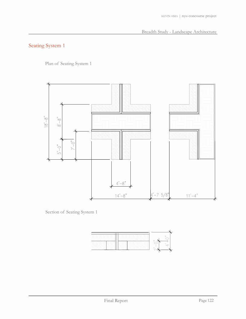
Breadth Study - Landscape Architecture
Final Report Page
kevin hsia | nyu concourse project
Seating System 1
Plan of Seating System 1
Section of Seating System 1
122

Breadth Study - Landscape Architecture
Final Report Page
kevin hsia | nyu concourse project
Seating System 2
Plan of Seating System 2
Section of Seating System 2
123

Breadth Study - Landscape Architecture
Final Report Page
kevin hsia | nyu concourse project
Rendering of Seating System 1
Original Plaza
Proposed Solution
124

Breadth Study - Landscape Architecture
Final Report Page
kevin hsia | nyu concourse project
Rendering of Seating System 2
Original Plaza
Proposed Solution
125

Breadth Study - Landscape Architecture
Final Report Page
kevin hsia | nyu concourse project
Rendering of Seating System 2
Seating System 1
Seating System 2
126

Breadth Study - Landscape Architecture
Final Report Page
kevin hsia | nyu concourse project
Rendering of Seating System 2
Proposed Solution
Design Summary
By creating a mix of different furniture systems, the design would help foster interactions amongst the New York University Community. The design is also able to introduce urban greenery into the plaza. The trees will provide a relaxing and laid back atmosphere. At the same time, the designed systemdoesnotinterruptthetrafficflowontheplaza.
127
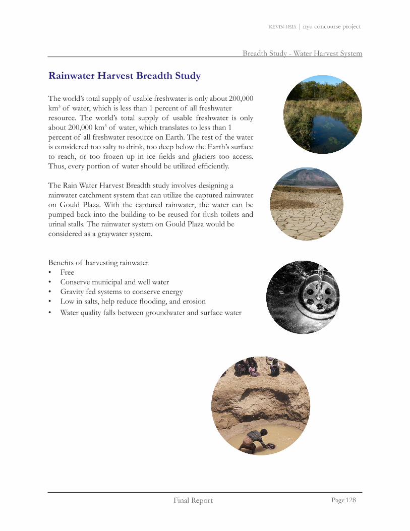
Breadth Study - Water Harvest System
Final Report Page
kevin hsia | nyu concourse project
The world’s total supply of usable freshwater is only about 200,000 km3 of water, which is less than 1 percent of all freshwater resource. The world’s total supply of usable freshwater is only about 200,000 km3 of water, which translates to less than 1 percent of all freshwater resource on Earth. The rest of the water is considered too salty to drink, too deep below the Earth’s surface to reach, or too frozen up in ice fields and glaciers too access.Thus,everyportionof watershouldbeutilizedefficiently.
The Rain Water Harvest Breadth study involves designing a rainwater catchment system that can utilize the captured rainwater on Gould Plaza. With the captured rainwater, the water can be pumpedbackintothebuildingtobereusedforflushtoiletsandurinal stalls. The rainwater system on Gould Plaza would be considered as a graywater system.
Benefitsof harvestingrainwaterFree•Conserve municipal and well water•Gravity fed systems to conserve energy•Lowinsalts,helpreduceflooding,anderosion•Water quality falls between groundwater and surface water •
Rainwater Harvest Breadth Study
128
Breadth Study - Water Harvest System
Final Report Page
kevin hsia | nyu concourse project
Construction of Water Harvest System
RainfallwouldbecapturedfromtheexistingstormdrainagesystembeneathGouldPlaza.Thefloorof Gould Plaza consists of 4’ x 4’ stone tiles elevated. The elevated stones have gaps on all four sides.Rainwaterwillnaturallyflowdownthegapsintothestormdrainagesystem.Therainwaterwillfirstgothroughawastewatertreatmentsystemtocleanthewaterandthengetdirectedtostorageinthe cistern. When water is needed, pumps will be used to pump the water back into the building.
Components needed for rainwater harvest systemCatchment Area: 25,500 sq. ft. Gould Plaza. •Pre-storagefiltration:Keepparticleanddebrisoutof cistern.•Rainwater conveyance: system of existing gutters, downspouts, and piping used to transport •water from the plaza back into the buildings.Watertreatmentsystem:treatwatercleanforurinalandtoiletflushing.•Ideal to remove particles down to 5 microns.•Cistern: Storage system for rain water harvest. •Water delivery: pump required to deliver water from cistern back to the building.•
Rainwater Harvest SystemPropose a dual waste piping system. One system would run collected •rain water to the tank. The second pipe would connect to a sewer line in caseof overflowof thegraywatercollection.Acontrolvalvewouldbeincludedsothegraywatercanbeswitchedtothesewerlinewhentheoverflowbecomesapparent.Graywater should not be stored for long a period. Microorganisms will used up oxygen and •anaerobic bacteria will take place. Creating unpleasant odors. Graywater may contain pathogens •
129

Breadth Study - Water Harvest System
Final Report Page
kevin hsia | nyu concourse project
Construction of Water Harvest System
Horizontal Areas Square Gutter Size
Size of Drain (in.) Flow (gpm) Feet at Rainfall Rates 4 144 14704 144 2115
Total Area of Plaza/allowable horizontal area = number of drainsNumber of Drain Needed
Plaza Area Allowable Area Drains Needed
12,750 1,470 912,750 2115 6
Total Area of Plaza/allowable horizontal area = number of drains
*Flow data from 1997 Uniform Plumbing Code*Maximum Allowable Horizontal Area From Existing NYU Concourse Drawing
The existing drain consists of two types of 4” drain. The drains handle 1,470 sq.ft. and 2,115 sq.ft. of rainfall. The large regions of the plaza will utilize the larger 4” drain to cover more water. The corners of the plaza will utilize the smaller 4” drain.
130
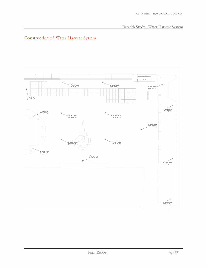
Breadth Study - Water Harvest System
Final Report Page
kevin hsia | nyu concourse project
Construction of Water Harvest System
131

Breadth Study - Water Harvest System
Final Report Page
kevin hsia | nyu concourse project
Data on New York City
Gould Plaza is located at the heart of the NYU Stern School of Business campus. Surrounded by Weaver Hall, Tisch Hall, and the Kaufman Center, Gould Plaza provides NYU students a place to relaxandhaveagoodtime.GouldPlazaisalsoamajortrafficintersectionsincetheentrancesof thethree buildings are connected to the plaza. The total area of Gould Plaza is 25,500 sq.ft.
Gould Plaza Section (view from east)
NYU Business School Campus
tisch hall
kmc
gould plaza
132

Breadth Study - Water Harvest System
Final Report Page
kevin hsia | nyu concourse project
Water Consumption of New York University
Water Usage (g/cd) Students + Staff Usages (gpd) Academic Year (gal) Estimated Academic Year (gal)
8 5,984 38297.6 5,553,152 3,887,206
Water Usage from NYU students
The water usage for NYU was determined by calculating the water usage of students and staff. For the academic school year of Fall 2008, there are a total of 5,984 members in the NYU community. These members include undergraduate students, MBA full time and part time students, PhD students, MS Global Finance students, and faculty members.
Thewaterusageforthisbreadthstudywillbethewaterconsumedbythetoiletandurinalflush.The toilets and urinals picked for NYU are low in water consumption usage. The toilet and urinal stallconsumes1.6gpf and1.0gpf respectively.If eachpersonwasestimatedtoflushthetoilet5times a day, the average per capita gallon usage would be 8. Furthermore, estimation have been made that only 80% of the student and faculty population would use the lavatory on a daily basis on the NYU campus. The calculation also takes into account the number of academic days, which is a total of 145 days for the 2008-2009 academic school year. This does not take into account the summer school year since the water usage of the summer will be a lot lower compared to the fall and spring school year. The total water usage for toilet and urinals for the 2008-2009 academic school year is 3,887,206 gallons.
September October November December Total days20 21 17 15 73
January Febuary March April May Total days5 19 17 22 9 72
NYU Academic Calender 2008-2009: Spring days of class
NYU Academic Calender 2008-2009: Fall days of class
133

Breadth Study - Water Harvest System
Final Report Page
kevin hsia | nyu concourse project
Gould Plaza Harvested Water
New York City is a suitable location to harvest water. The annual average rainfall is 41.5 inches. On average, New York City receives about 3 inches of rain. The calculated harvest water on Gould Plaza is 4,749,426 gallons per year. This number was determined by multiplying the average New York City rainfallandthesquarefootageof GouldPlaza.Assumingthattheefficiencyof theharvestwatersystem is at 60%, the total water captured would be 4,749,426 gallons.
Area (sq.ft.) Average Rainfall NYC (inch)
Average Rainfall NYC/month (ft3) Total Rainfall (ft3)
Volume needed at 60% efficency (ft3)
Gallons needed per year
25,500 41.50 88,188 1,058,250 634,950 4,749,426
Gould Plaza Average Rainfall
Jan Feb Mar Apr May Jun Jul Aug Sep Oct Nov Dec Yearmm 80.9 73 92.1 91.8 103.4 82.6 94.5 94 87.6 75.9 88.2 89.2 1054.3inches 3.2 2.9 3.6 3.6 4.1 3.3 3.7 3.7 3.4 3 3.5 3.5 41.5
*data from NCDC Cooperative Stations
Averge Rainfall of New York City
Calculate water produced by Gould Plaza:(Area of Plaza) x (Average Rainfall NYC) = Total Rainfall Itisassumedthatthedrainagesystemof GouldPlazawouldonlybe60efficient.The total water produced would be 60% of the water produced.
134

Breadth Study - Water Harvest System
Final Report Page
kevin hsia | nyu concourse project
Gould Plaza Harvested Water
135

Breadth Study - Water Harvest System
Final Report Page
kevin hsia | nyu concourse project
Key Components of Waste Water Treatment
ZeeWeed 1000 Ultrafiltration Membranes
Login | Register | Contact Us | Site Map
search Industries Solutions Products About Us
● Home
● Products
● Equipment
● MF / UF / MBR
● Ultrafiltration (UF)
● ZeeWeed 500
● ZeeWeed 1000
● ZeeWeed 1500
● Packaged UF Plants
● Contact Us
The Equipment
A full-scale ZeeWeed treatment facility is comprised of a given number of modular components: modules, cassettes, and trains.
A module is the basic building block and the heart of a ZeeWeed system. Each module contains thousands of horizontally strung membrane fibers that have millions of microscopic pores in each strand. Water is filtered by applying a slight vacuum to the end of each fiber which draws the water through the tiny pores and into the fibers themselves. The pores form a physical barrier that allows clean water to pass through while blocking unwanted material such as suspended solids, bacteria, pathogens and certain viruses.
Modules are joined together to form a cassette, which is the smallest operable unit of the filtration system. Each cassette can have a variety of module configurations depending on the amount of water that the cassette is required to treat.
http://www.gewater.com/products/equipment/mf_uf_mbr/zeeweed_1000.jsp (1 of 4) [3/24/2009 3:05:08 PM]
Waste Water System: GE ZeeWeed 500
The ZeeWeed 500 would be a perfect waste water treatment system for the harvested rainwater. The system measures 3’x 6’x 8’. Water isfilteredthroughthemicroscopicporesineachstrand.Suspendedsolids, bacteria, pathogens, and certain viruses can be blocked off. The wastewater system treats about 13,000 gallons per day.
Cistern
The tank would store about 30,000 gallons of treated water. That is equivalent to about two days of rainwater. The cistern would measure to be about 15’ x 10’ x 9’. Weaver Hall , Tisch Hall, and the Kaufman Center will each have its own cistern in the basement. Each tank will hold about 10,000 gal-lons of water.
It is recommended that the captured water from Gould Plaza is treated. The graywater may contain pathogens and viruses.
136
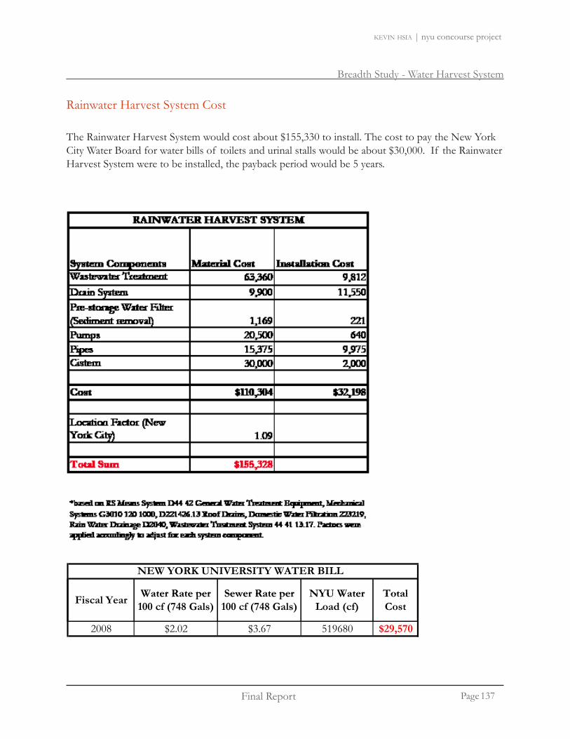
Breadth Study - Water Harvest System
Final Report Page
kevin hsia | nyu concourse project
Rainwater Harvest System Cost
The Rainwater Harvest System would cost about $155,330 to install. The cost to pay the New York City Water Board for water bills of toilets and urinal stalls would be about $30,000. If the Rainwater Harvest System were to be installed, the payback period would be 5 years.
Water Rate per Sewer Rate per NYU Water Total
NEW YORK UNIVERSITY WATER BILL
Fiscal Year Water Rate per 100 cf (748 Gals)
Sewer Rate per 100 cf (748 Gals)
NYU Water Load (cf)
Total Cost
2008 $2.02 $3.67 519680 $29,570
*based on data from New York City Water Board Rate Schedule for Fiscal Year 2008. The calculatedbased on data from New York City Water Board Rate Schedule for Fiscal Year 2008. The calculated water bill only covers the water usage from toilets and urinal stalls
137

Breadth Study - Water Harvest System
Final Report Page
kevin hsia | nyu concourse project
Water Harvest Treatment
The rainwater harvest system implemented in Gould Plaza can help NYU save water. The produced water for Gould Plaza is more than enough for the water consumed by the NYU community. Overall, there will be a surplus of 862,220 gallons of water. The payback period for the rainwater harvest system would only be about 5 years.
The rainwater harvesting system would also help promote New York University’s reputation as a environmentally conscious university. Already, New York University’s Sustainable Task Force sponsors a number of ‘Green Grants’ to promote sustainability. New York University is also one of the top buyers of green energy among national universities.
It is recommended that New York University consider the construction of a Water Harvest System at Gould Plaza.
138
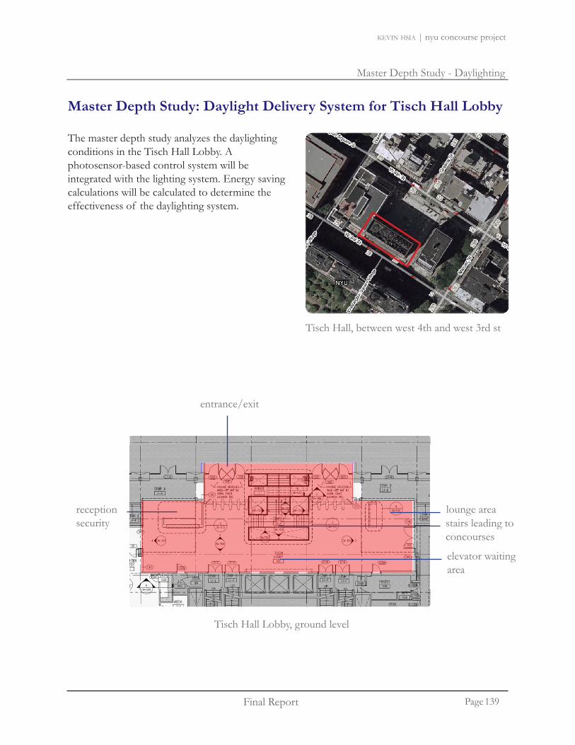
Master Depth Study - Daylighting
Final Report Page
kevin hsia | nyu concourse project
Tisch Hall, between west 4th and west 3rd st
Tisch Hall Lobby, ground level
lounge area
entrance/exit
receptionsecurity
elevator waitingarea
stairs leading toconcourses
The master depth study analyzes the daylighting conditions in the Tisch Hall Lobby. A photosensor-based control system will be integrated with the lighting system. Energy saving calculations will be calculated to determine the effectiveness of the daylighting system.
Master Depth Study: Daylight Delivery System for Tisch Hall Lobby
139
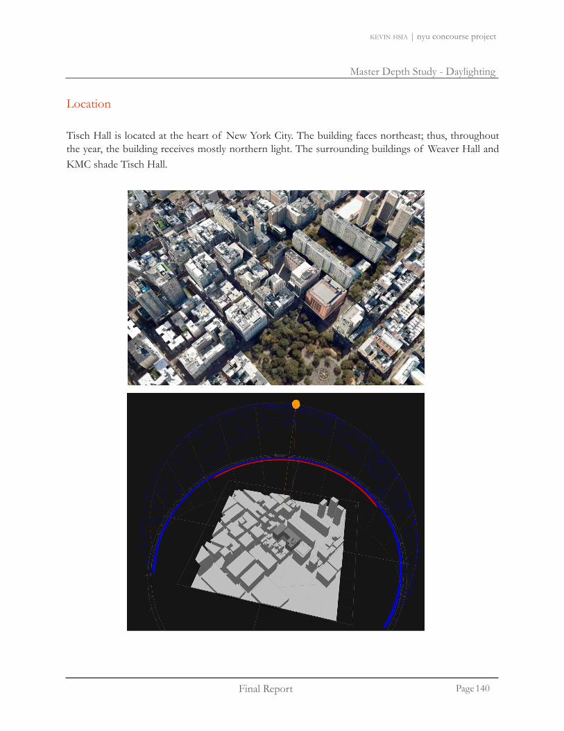
Master Depth Study - Daylighting
Final Report Page
kevin hsia | nyu concourse project
lounge area
elevator waitingarea
Tisch Hall is located at the heart of New York City. The building faces northeast; thus, throughout the year, the building receives mostly northern light. The surrounding buildings of Weaver Hall and KMC shade Tisch Hall.
Location
140

Master Depth Study - Daylighting
Final Report Page
kevin hsia | nyu concourse project
AGI Psuedo Rendering (Top View)
AGI Psuedo Rendering (Interior)
141

Master Depth Study - Daylighting
Final Report Page
kevin hsia | nyu concourse project
Daylight Simulation
The Tisch model is constructed in AGI32. The mesh sizes are increased to 4.2 for accurate computer calculations.Themullionsareconstructedasseparateobjectstofitwiththewindowtohelpmakethereadings more accurate. The canopy to the front entry of Tisch Hall and Gould Plaza are also constructed.Thesurfaceof GouldPlazawillhelpreflectlightintotheTischLobby.
142

Master Depth Study - Daylighting
Final Report Page
kevin hsia | nyu concourse project
Materials for Tisch Lobby
Type Description Finish Reflectance (assumed)
Wall
ST-2 Batek Diamante Limestone (smooth) Grey 0.5
WD-2 Bamboo Patina panel Light Brown 0.3P-1 White finish Eggshell 0.9
Wall Base FinishST-2 Batek Diamante Limestone Grey 0.5
CT-5B Gateway Ceramic Flooring Sterling Grey 0.3FlooringCT-5A Gateway Ceramic Flooring Sterling Grey 0.3Ceiling
ST-2 Batek Diamante Limestone GreyACT-5 Bamboo Patina panel Light Brown 0.9
P-1 White finish Eggshell 0.9
Finishes for Tisch Lobby
Tisch Hall is made up of several materials. The AGI model is simplified to make the walls and ceiling have one reflectance value.
In the study for the daylighting model, the reflectance for the wall is 0.5 (since most of the wall is covered with limestone), the reflectance of the floor is 0.3, and the ceiling is 0.9. The transmittance of the glass is 0.6.
143

Master Depth Study - Daylighting
Final Report Page
kevin hsia | nyu concourse project
Proposed Photosensor System
A photosensor based daylighting system can help Tisch Hall save energy. The operation hours of Tisch Hall will assume to be from 8 am to midnight. The lobby can utilize the consistent northern light to help illuminate the space. At certain times throughout the year, the corners of the lobby does not obtain the 10 fc recommended by the IES. For the proposed photosensor system design, the proposal is to recommend 15 fc throughout the lobby. With the increase of lighting, it would provide a brighter space which can help make the space feel larger and comfortable for occupants.
The lighting in the lobby will be divided into three zones. Zone 1 lights will be based on an astronomical clock. Zone 1 lighting will not need to be turned on for the majority of the day (8am to 5 pm) due to the ample daylight coming through the window. Zone 2 lighting be part of a photosensor based system. The lighting will dim to achieve the 15 fc proposed design for the corners of the lobby. Zone 3 are lights that will always be turned on - these include the recessed fluorescentsinthewallandthependantsof thesecuritydeskandstairs.
A model was constructed in agi32 and ecotect to analyze the daylighting conditions throughout the year. The photosensor designed is based on the time of the year when the lobby receives the least amount of daylight. Calculations were run three times a day at 9:00 AM, 12:00 PM, and 3:00 PM on the equinox, summer and winter solstice. The calculations show that during the winter solstice, Tisch Hall receives the least amount of light.
The photosensor will be based off of the winter solstice at 3 pm. The dimming level wasdeterminedbyfindingthecriticalpoint,asinglepointwithinaspacethatestablishesthecontribution from the dimmed lighting zone that will required to make up for the difference between the target illuminance and the illuminance from daylight and non dimmed lighting.
The photosensor location will be imported into the ecotect model of Tisch Hall and analyzed in daysim for energy analysis.
144

Master Depth Study - Daylighting
Final Report Page
kevin hsia | nyu concourse project
Proposed Photosensor System
Zone 1
Zone 2
Always on
Tisch Hall Lobby, ground level
145

Master Depth Study - Daylighting
Final Report Page
kevin hsia | nyu concourse project
March 21 - 9 am, overcast day
March 21 - 12 pm, overcast day
March 21 - 3 pm, overcast day
146

Master Depth Study - Daylighting
Final Report Page
kevin hsia | nyu concourse project
6.9 7.5 7.9 8.9 10.2 11.7 13.0 14.2 15.0 15.8 16.0 15.9 15.9 15.4 14.9 14.9 15.0 15.0 15.0 15.5 16.0 16.0 16.1 15.7 15.0 14.1 13.0 11.6 10.1 8.7 8.1 7.8 7.2
8.4 8.2 8.2 8.8 9.9 11.1 12.6 13.9 14.8 15.6 15.8 15.4 14.4 12.6 11.7 11.8 11.9 11.8 11.7 12.8 14.5 15.4 15.8 15.5 14.8 13.8 12.5 11.0 9.7 8.7 8.3 8.4 8.6
11.2 8.9 8.3 8.8 9.9 11.2 12.9 14.5 15.5 16.5 16.9 16.3 14.8 11.1 11.0 11.1 11.1 11.2 11.0 11.1 14.8 16.3 16.8 16.4 15.6 14.3 12.8 11.2 9.7 8.7 8.3 9.1 11.4
8.8 8.2 8.0 8.6 9.7 11.6 13.6 15.8 17.3 18.6 19.4 18.8 14.7 9.1 8.6 9.6 8.6 9.6 8.7 9.1 14.8 18.7 19.2 18.4 17.3 15.8 13.6 11.4 9.6 8.6 8.0 8.4 8.8
7.3 7.5 7.5 8.3 9.5 11.9 14.9 17.9 20.1 21.6 22.9 23.0 16.2 21.9 22.6 22.8 22.9 22.8 22.6 21.8 16.6 23.0 22.7 21.6 20.0 17.9 14.8 11.7 9.5 8.1 7.6 7.9 7.4
9.4 7.5 7.1 7.7 9.0 11.8 16.4 21.2 23.9 26.0 27.1 27.5 28.2 26.8 27.3 28.2 28.4 28.1 27.3 26.9 28.0 27.5 27.0 25.9 23.8 21.0 16.2 11.6 8.9 7.4 7.0 7.8 9.6
8.2 6.7 6.3 6.4 7.6 11.1 17.7 25.7 29.9 32.6 33.5 32.1 32.8 28.3 32.1 33.1 33.2 33.0 32.0 28.2 32.6 32.3 33.4 32.5 29.6 25.4 17.3 10.8 7.8 6.3 6.1 6.8 8.2
5.0 5.1 5.1 5.4 5.9 8.2 16.9 32.2 38.7 42.8 44.0 41.2 30.2 29.6 33.6 34.5 34.6 34.5 33.7 29.6 30.7 41.3 43.9 42.6 38.6 32.0 16.2 7.9 5.9 5.3 5.3 5.2 4.9
3.5 4.0 4.3 4.5 4.6 5.2 6.8 43.8 53.9 59.1 60.5 57.2 39.3 16.5 16.9 17.0 17.1 16.9 16.9 16.5 39.7 57.3 60.7 59.2 53.7 43.3 6.5 5.0 4.7 4.4 4.2 4.2 3.6
67.6 77.7 84.2 84.2 78.3 69.0 50.9 47.1 48.0 49.0 47.9 47.1 51.2 69.3 78.8 84.5 84.3 77.6 65.4
98.7 116 124 123 111 77.9 18.2 11.7 24.0 11.9 23.9 11.9 18.1 79.0 111 122 124 116 93.4
143 174 171 174 163 113 131 163 169 164 169 163 127 116 163 173 166 170 141
Calculation SummaryLabel CalcType Units Avg Max Min Avg/Min Max/Min Max/Avg # Pts DescriptionLobby Illuminance Fc 25.31 174 0.0 N.A. N.A. N.A. 408Tisch Lobby Illuminance Fc 30.40 174 3.5 8.69 49.63 N.A. 354 not for export
9.3 10.0 10.6 12.1 14.1 16.3 18.1 20.0 21.1 22.2 22.6 22.5 22.5 21.8 21.1 21.0 21.2 21.2 21.1 21.9 22.6 22.6 22.7 22.1 21.1 19.8 18.2 16.2 14.0 11.9 10.9 10.3 9.6
10.6 10.5 10.8 12.0 13.6 15.4 17.6 19.5 20.8 22.0 22.3 21.7 20.4 17.9 16.5 16.7 16.8 16.7 16.5 18.0 20.5 21.7 22.3 21.8 20.8 19.3 17.5 15.3 13.3 11.8 11.0 10.9 10.9
13.3 11.2 10.8 11.9 13.6 15.6 18.0 20.4 21.9 23.3 23.8 23.0 20.9 15.6 15.5 15.7 15.7 15.7 15.5 15.7 20.9 23.0 23.7 23.1 21.9 20.1 17.8 15.5 13.2 11.7 10.9 11.4 13.6
10.8 10.4 10.5 11.6 13.3 16.0 19.0 22.2 24.4 26.2 27.3 26.5 20.8 12.9 12.1 13.6 12.2 13.6 12.2 12.8 20.9 26.4 27.2 26.0 24.4 22.1 18.9 15.7 13.1 11.6 10.4 10.6 10.7
9.1 9.4 9.8 11.1 13.0 16.5 20.8 25.2 28.3 30.5 32.4 32.5 22.9 31.1 32.1 32.3 32.4 32.3 32.1 30.9 23.5 32.6 32.1 30.4 28.2 25.2 20.7 16.2 13.0 10.8 9.8 10.0 9.2
11.0 9.2 9.2 10.2 12.3 16.3 23.0 29.8 33.8 36.7 38.4 38.9 39.9 38.0 38.8 39.9 40.3 39.8 38.7 38.2 39.7 38.9 38.2 36.7 33.6 29.6 22.8 16.0 12.1 9.8 9.1 9.5 11.2
9.5 8.3 8.1 8.5 10.3 15.4 24.9 36.3 42.3 46.2 47.5 45.5 46.5 40.1 45.5 46.9 47.0 46.8 45.4 39.9 46.2 45.8 47.4 46.0 41.9 35.9 24.3 15.0 10.6 8.4 7.8 8.4 9.6
6.2 6.5 6.6 7.2 7.9 11.4 23.7 45.6 54.8 60.7 62.4 58.4 42.8 42.0 47.7 49.0 49.1 49.0 47.9 41.9 43.5 58.5 62.3 60.4 54.7 45.2 22.7 10.9 7.9 7.1 6.9 6.6 6.2
4.5 5.2 5.6 6.0 6.2 7.1 9.4 62.1 76.4 83.9 85.8 81.2 55.7 23.3 23.9 24.0 24.1 23.9 24.0 23.3 56.4 81.4 86.1 84.0 76.3 61.4 8.9 6.8 6.3 5.9 5.5 5.5 4.8
96.1 110 120 120 111 98.0 72.3 66.9 68.2 69.7 68.1 67.0 72.7 98.4 112 120 120 110 93.0
140 165 176 174 157 111 25.8 16.5 34.0 16.8 33.9 16.8 25.7 112 158 174 176 165 133
203 247 243 247 231 160 187 232 241 233 240 231 180 165 232 246 236 242 200
Calculation SummaryLabel CalcType Units Avg Max Min Avg/Min Max/Min Max/Avg # Pts DescriptionLobby Illuminance Fc 35.67 247 0.0 N.A. N.A. N.A. 408Tisch Lobby Illuminance Fc 42.88 247 4.5 9.53 54.87 N.A. 354 not for export
7.1 7.6 8.1 9.1 10.5 12.0 13.3 14.6 15.4 16.2 16.4 16.3 16.3 15.8 15.3 15.2 15.4 15.4 15.3 15.9 16.4 16.4 16.5 16.1 15.4 14.4 13.3 11.9 10.4 8.9 8.3 7.9 7.3
8.6 8.3 8.3 9.0 10.1 11.4 12.9 14.2 15.2 16.0 16.2 15.8 14.8 13.0 12.0 12.1 12.2 12.1 12.0 13.1 14.9 15.8 16.2 15.9 15.2 14.1 12.8 11.3 9.9 8.9 8.5 8.6 8.8
11.4 9.1 8.4 9.0 10.1 11.5 13.2 14.9 15.9 16.9 17.3 16.7 15.2 11.4 11.3 11.4 11.4 11.4 11.3 11.4 15.2 16.7 17.2 16.8 16.0 14.7 13.1 11.5 9.9 8.9 8.5 9.2 11.6
8.9 8.4 8.2 8.8 9.9 11.9 13.9 16.3 17.8 19.1 19.9 19.3 15.1 9.4 8.8 9.9 8.8 9.9 8.9 9.3 15.2 19.1 19.7 18.9 17.7 16.2 13.9 11.6 9.8 8.8 8.1 8.5 8.9
7.4 7.6 7.7 8.4 9.7 12.2 15.3 18.4 20.6 22.2 23.5 23.6 16.6 22.5 23.2 23.4 23.5 23.4 23.2 22.3 17.0 23.6 23.3 22.1 20.5 18.4 15.2 12.0 9.7 8.3 7.7 8.0 7.5
9.5 7.6 7.2 7.8 9.2 12.1 16.8 21.7 24.5 26.7 27.8 28.2 28.9 27.5 28.0 28.9 29.2 28.8 28.0 27.6 28.7 28.2 27.7 26.6 24.4 21.6 16.7 11.8 9.1 7.5 7.2 7.9 9.7
8.2 6.8 6.4 6.5 7.8 11.4 18.2 26.4 30.7 33.5 34.4 32.9 33.7 29.0 32.9 33.9 34.0 33.9 32.8 28.9 33.4 33.2 34.3 33.3 30.4 26.1 17.7 11.1 7.9 6.4 6.2 6.9 8.3
5.0 5.2 5.2 5.5 6.0 8.4 17.3 33.1 39.7 43.9 45.1 42.2 31.0 30.4 34.5 35.4 35.5 35.4 34.6 30.3 31.5 42.4 45.1 43.7 39.6 32.8 16.6 8.1 6.0 5.4 5.4 5.3 5.0
3.5 4.1 4.4 4.6 4.7 5.3 7.0 44.9 55.3 60.6 62.0 58.7 40.3 16.9 17.3 17.4 17.5 17.3 17.4 16.9 40.8 58.9 62.3 60.8 55.2 44.4 6.6 5.1 4.8 4.5 4.3 4.3 3.7
69.4 79.7 86.4 86.4 80.4 70.8 52.2 48.3 49.3 50.3 49.2 48.4 52.5 71.1 80.9 86.7 86.5 79.7 67.1
101 119 127 126 113 80.0 18.7 11.9 24.6 12.1 24.5 12.1 18.6 81.1 114 126 127 119 95.8
146 178 176 178 167 116 135 168 174 168 174 167 130 119 168 178 171 175 144
Calculation SummaryLabel CalcType Units Avg Max Min Avg/Min Max/Min Max/Avg # Pts DescriptionLobby Illuminance Fc 25.96 179 0.0 N.A. N.A. N.A. 408Tisch Lobby Illuminance Fc 31.18 178 3.5 8.91 50.94 N.A. 354 not for export
March 21, 9 am, overcast day
March 21, 12 pm, overcast day
March 21, 3 pm, overcast day
Numbers in Red represent over 10 fc
147

Master Depth Study - Daylighting
Final Report Page
kevin hsia | nyu concourse project
June 21, 9 am, overcast day
June 21, 12 pm, overcast day
June 21, 3 pm, overcast day
148

Master Depth Study - Daylighting
Final Report Page
kevin hsia | nyu concourse project
9.3 9.9 10.6 12.1 14.1 16.3 18.1 19.9 21.1 22.2 22.6 22.4 22.5 21.8 21.0 21.0 21.2 21.1 21.1 21.8 22.5 22.6 22.6 22.1 21.1 19.7 18.2 16.2 14.0 11.9 10.9 10.3 9.6
10.6 10.5 10.8 11.9 13.6 15.4 17.5 19.4 20.7 21.9 22.3 21.7 20.4 17.8 16.4 16.7 16.8 16.7 16.5 18.0 20.5 21.7 22.3 21.8 20.8 19.3 17.5 15.3 13.3 11.8 11.0 10.9 10.9
13.3 11.2 10.8 11.8 13.6 15.6 17.9 20.3 21.8 23.2 23.8 23.0 20.8 15.6 15.5 15.7 15.7 15.7 15.5 15.6 20.9 23.0 23.7 23.1 21.8 20.0 17.8 15.5 13.2 11.7 10.9 11.3 13.5
10.8 10.3 10.5 11.6 13.3 16.0 18.9 22.2 24.3 26.2 27.3 26.5 20.8 12.9 12.1 13.6 12.2 13.6 12.2 12.8 20.9 26.3 27.1 26.0 24.3 22.1 18.9 15.7 13.1 11.6 10.4 10.6 10.7
9.0 9.4 9.8 11.1 12.9 16.4 20.8 25.2 28.2 30.5 32.3 32.5 22.8 31.0 32.0 32.3 32.4 32.3 32.0 30.8 23.4 32.5 32.1 30.4 28.1 25.2 20.7 16.2 13.0 10.8 9.8 10.0 9.2
11.0 9.2 9.2 10.2 12.3 16.3 23.0 29.8 33.7 36.7 38.3 38.8 39.9 38.0 38.7 39.9 40.3 39.7 38.6 38.1 39.6 38.8 38.2 36.6 33.5 29.6 22.7 16.0 12.1 9.8 9.0 9.5 11.1
9.5 8.3 8.1 8.5 10.3 15.4 24.8 36.2 42.2 46.1 47.4 45.4 46.5 40.0 45.4 46.8 47.0 46.8 45.3 39.9 46.1 45.7 47.3 45.9 41.8 35.9 24.3 15.0 10.6 8.3 7.8 8.4 9.6
6.2 6.5 6.6 7.2 7.9 11.3 23.7 45.5 54.8 60.6 62.3 58.3 42.8 42.0 47.6 48.9 49.0 48.9 47.8 41.9 43.4 58.5 62.2 60.3 54.6 45.1 22.7 10.9 7.9 7.0 6.9 6.6 6.2
4.5 5.2 5.6 6.0 6.2 7.1 9.5 62.0 76.3 83.7 85.7 81.0 55.6 23.3 23.9 24.0 24.1 23.9 23.9 23.3 56.3 81.3 86.0 83.9 76.1 61.2 8.9 6.8 6.3 5.9 5.5 5.5 4.7
95.9 110 119 119 111 97.8 72.2 66.8 68.1 69.6 68.0 66.9 72.6 98.3 112 120 120 110 92.8
140 165 175 174 157 111 25.8 16.5 33.9 16.7 33.8 16.8 25.6 112 157 174 176 164 133
202 247 243 247 231 160 186 232 240 233 240 231 180 165 232 246 236 242 200
Calculation SummaryLabel CalcType Units Avg Max Min Avg/Min Max/Min Max/Avg # Pts DescriptionLobby Illuminance Fc 35.61 247 0.0 N.A. N.A. N.A. 408Tisch Lobby Illuminance Fc 42.81 247 4.5 9.51 54.78 N.A. 354 not for export
11.3 12.1 13.0 14.9 17.5 20.2 22.6 24.9 26.4 27.8 28.3 28.1 28.2 27.3 26.4 26.3 26.6 26.5 26.5 27.4 28.2 28.3 28.3 27.6 26.4 24.7 22.7 20.1 17.3 14.6 13.3 12.6 11.7
12.5 12.5 13.1 14.7 16.8 19.1 21.9 24.3 25.9 27.4 27.9 27.1 25.5 22.3 20.6 20.9 21.0 20.9 20.6 22.5 25.6 27.1 27.9 27.3 26.0 24.1 21.8 19.0 16.5 14.5 13.3 13.0 12.9
15.1 13.1 13.1 14.5 16.7 19.3 22.3 25.4 27.3 29.1 29.8 28.8 26.1 19.5 19.4 19.7 19.7 19.7 19.4 19.6 26.2 28.8 29.7 28.9 27.3 25.0 22.2 19.2 16.3 14.3 13.1 13.3 15.4
12.5 12.2 12.6 14.1 16.3 19.9 23.6 27.8 30.5 32.8 34.2 33.2 26.0 16.1 15.2 17.0 15.2 17.0 15.3 16.0 26.1 33.0 34.0 32.5 30.4 27.6 23.6 19.5 16.1 14.1 12.5 12.4 12.4
10.6 11.0 11.7 13.5 16.0 20.4 25.9 31.5 35.4 38.2 40.5 40.7 28.6 38.9 40.2 40.5 40.6 40.5 40.2 38.7 29.4 40.8 40.2 38.1 35.2 31.5 25.8 20.1 16.0 13.2 11.7 11.8 10.7
12.3 10.6 11.0 12.4 15.2 20.3 28.7 37.3 42.3 46.0 48.1 48.7 50.0 47.7 48.6 50.1 50.5 49.9 48.5 47.9 49.8 48.7 47.9 45.9 42.0 37.0 28.4 19.9 14.9 11.9 10.8 11.0 12.5
10.7 9.6 9.7 10.3 12.7 19.1 31.0 45.4 53.0 57.9 59.5 57.0 58.3 50.2 57.0 58.8 59.0 58.7 56.9 50.1 57.9 57.4 59.4 57.6 52.4 44.9 30.3 18.6 13.0 10.1 9.3 9.7 10.7
7.3 7.7 7.9 8.7 9.6 14.0 29.6 57.1 68.7 76.1 78.2 73.2 53.7 52.7 59.8 61.4 61.5 61.4 60.0 52.6 54.6 73.4 78.1 75.7 68.5 56.6 28.3 13.5 9.7 8.5 8.3 7.7 7.3
5.4 6.2 6.8 7.3 7.6 8.7 11.7 77.8 95.8 105 108 102 69.9 29.2 30.0 30.1 30.2 30.0 30.0 29.2 70.7 102 108 105 95.6 76.9 11.1 8.4 7.7 7.1 6.5 6.5 5.7
121 139 150 150 140 123 90.7 84.0 85.6 87.5 85.4 84.1 91.3 124 140 151 150 138 117
176 207 221 219 197 139 32.4 20.7 42.7 21.0 42.5 21.0 32.2 141 198 218 221 207 167
254 310 306 310 291 201 234 291 302 293 302 290 226 207 291 309 297 304 251
Calculation SummaryLabel CalcType Units Avg Max Min Avg/Min Max/Min Max/Avg # Pts DescriptionLobby Illuminance Fc 44.58 311 0.0 N.A. N.A. N.A. 408Tisch Lobby Illuminance Fc 53.61 310 5.4 9.93 57.39 N.A. 354 not for export
9.1 9.8 10.5 12.0 13.9 16.1 17.9 19.7 20.8 21.9 22.3 22.2 22.2 21.5 20.7 20.7 20.9 20.8 20.8 21.5 22.2 22.3 22.3 21.8 20.8 19.5 17.9 16.0 13.8 11.7 10.8 10.2 9.5
10.5 10.4 10.7 11.8 13.4 15.2 17.3 19.2 20.5 21.6 22.0 21.4 20.1 17.6 16.2 16.4 16.5 16.4 16.2 17.7 20.2 21.4 22.0 21.5 20.5 19.1 17.2 15.1 13.2 11.7 10.8 10.7 10.8
13.2 11.1 10.7 11.7 13.4 15.4 17.7 20.1 21.5 22.9 23.5 22.6 20.6 15.4 15.3 15.5 15.5 15.5 15.3 15.4 20.6 22.7 23.4 22.8 21.6 19.8 17.6 15.3 13.1 11.5 10.7 11.2 13.4
10.7 10.2 10.4 11.4 13.1 15.8 18.7 21.9 24.0 25.8 26.9 26.1 20.5 12.7 12.0 13.4 12.0 13.4 12.0 12.6 20.6 26.0 26.8 25.6 24.0 21.8 18.7 15.5 12.9 11.4 10.3 10.5 10.6
9.0 9.3 9.7 10.9 12.8 16.2 20.5 24.9 27.9 30.1 31.9 32.0 22.5 30.6 31.6 31.8 31.9 31.9 31.6 30.4 23.1 32.1 31.7 30.0 27.7 24.9 20.4 16.0 12.8 10.7 9.7 9.9 9.1
10.9 9.1 9.1 10.1 12.2 16.1 22.7 29.4 33.3 36.2 37.8 38.3 39.3 37.4 38.2 39.3 39.7 39.2 38.1 37.6 39.1 38.3 37.7 36.1 33.1 29.2 22.4 15.8 11.9 9.7 8.9 9.4 11.1
9.5 8.2 8.0 8.4 10.2 15.2 24.5 35.7 41.7 45.5 46.8 44.8 45.8 39.5 44.8 46.2 46.3 46.1 44.7 39.3 45.5 45.1 46.7 45.3 41.2 35.4 23.9 14.8 10.4 8.2 7.7 8.3 9.5
6.2 6.4 6.5 7.1 7.8 11.2 23.4 44.9 54.0 59.8 61.4 57.5 42.2 41.4 47.0 48.2 48.3 48.2 47.1 41.3 42.9 57.7 61.4 59.4 53.8 44.5 22.4 10.8 7.8 7.0 6.8 6.5 6.1
4.5 5.1 5.6 5.9 6.1 7.0 9.3 61.2 75.3 82.6 84.5 80.0 54.9 23.0 23.6 23.6 23.8 23.6 23.6 23.0 55.5 80.2 84.8 82.7 75.1 60.4 8.8 6.7 6.2 5.8 5.4 5.4 4.7
94.6 109 118 118 110 96.5 71.2 65.9 67.2 68.6 67.0 66.0 71.6 96.9 110 118 118 109 91.5
138 163 173 172 155 109 25.4 16.2 33.5 16.5 33.4 16.5 25.3 111 155 171 173 162 131
200 243 240 243 228 158 184 229 237 230 237 228 178 162 228 242 233 238 197
Calculation SummaryLabel CalcType Units Avg Max Min Avg/Min Max/Min Max/Avg # Pts DescriptionLobby Illuminance Fc 35.14 244 0.0 N.A. N.A. N.A. 408Tisch Lobby Illuminance Fc 42.24 243 4.5 9.39 54.04 N.A. 354 not for export
June 21, 9 am, overcast day
June 21, 12 pm, overcast day
June 21, 3 pm, overcast day
Numbers in Red represent over 10 fc
149

Master Depth Study - Daylighting
Final Report Page
kevin hsia | nyu concourse project
December 21, 9 am, overcast day
December 21, 12 pm, overcast day
December 21, 3 pm, overcast day
150

Master Depth Study - Daylighting
Final Report Page
kevin hsia | nyu concourse project
4.0 4.4 4.5 4.9 5.4 6.0 6.6 7.1 7.4 7.8 7.9 7.8 7.8 7.5 7.3 7.2 7.3 7.3 7.3 7.5 7.8 7.8 7.9 7.7 7.4 7.0 6.6 6.0 5.4 4.8 4.6 4.6 4.2
5.7 5.3 4.9 4.9 5.3 5.8 6.4 7.0 7.3 7.7 7.8 7.5 7.1 6.2 5.7 5.8 5.8 5.8 5.7 6.3 7.1 7.5 7.8 7.6 7.4 6.9 6.4 5.7 5.2 4.9 4.9 5.4 5.8
8.7 6.1 5.1 5.0 5.4 5.9 6.6 7.3 7.7 8.1 8.3 8.0 7.2 5.5 5.4 5.5 5.5 5.5 5.4 5.5 7.3 8.0 8.3 8.1 7.7 7.2 6.5 5.9 5.2 5.0 5.1 6.2 8.8
6.4 5.6 5.0 5.0 5.3 6.0 6.9 7.9 8.6 9.1 9.5 9.2 7.2 4.5 4.2 4.7 4.2 4.7 4.3 4.5 7.2 9.1 9.4 9.1 8.6 7.9 6.9 6.0 5.2 5.0 5.0 5.7 6.3
5.1 5.2 4.8 4.8 5.2 6.2 7.5 8.9 9.9 10.6 11.2 11.2 7.9 10.6 10.9 11.0 11.0 11.0 10.9 10.5 8.1 11.2 11.1 10.6 9.8 8.9 7.5 6.1 5.2 4.7 4.8 5.4 5.2
7.5 5.4 4.6 4.5 4.9 6.1 8.3 10.5 11.7 12.7 13.2 13.3 13.6 12.9 13.2 13.6 13.7 13.5 13.2 13.0 13.5 13.3 13.1 12.6 11.7 10.4 8.2 6.0 4.9 4.4 4.5 5.6 7.6
6.4 4.9 4.1 3.8 4.2 5.8 8.9 12.6 14.6 15.8 16.2 15.5 15.8 13.6 15.5 15.9 16.0 15.9 15.4 13.6 15.7 15.6 16.2 15.8 14.4 12.5 8.7 5.7 4.3 3.8 4.0 4.9 6.5
3.4 3.5 3.3 3.2 3.3 4.4 8.4 15.7 18.7 20.7 21.2 19.8 14.6 14.3 16.2 16.6 16.6 16.6 16.2 14.2 14.8 19.9 21.2 20.6 18.7 15.6 8.1 4.2 3.3 3.2 3.4 3.5 3.3
2.2 2.6 2.7 2.7 2.7 2.9 3.6 21.2 25.9 28.4 29.0 27.5 18.9 8.0 8.2 8.2 8.2 8.2 8.2 8.0 19.1 27.5 29.2 28.5 25.9 20.9 3.4 2.8 2.7 2.7 2.6 2.6 2.2
32.4 37.3 40.4 40.4 37.6 33.1 24.3 22.5 23.0 23.5 22.9 22.5 24.5 33.2 37.8 40.5 40.4 37.2 31.3
47.2 55.6 59.2 58.7 52.9 37.3 8.8 5.6 11.5 5.7 11.5 5.7 8.7 37.8 53.1 58.6 59.3 55.4 44.7
68.2 83.0 81.9 83.1 77.9 53.9 62.8 78.1 80.9 78.4 80.8 77.8 60.7 55.4 78.0 82.8 79.5 81.4 67.3
Calculation SummaryLabel CalcType Units Avg Max Min Avg/Min Max/Min Max/Avg # Pts DescriptionLobby Illuminance Fc 12.50 83.2 0.0 N.A. N.A. N.A. 408Tisch Lobby Illuminance Fc 14.96 83.1 2.2 6.80 37.77 N.A. 354 not for export
6.0 6.5 6.8 7.6 8.6 9.8 10.9 11.9 12.5 13.1 13.3 13.2 13.3 12.8 12.4 12.3 12.5 12.4 12.4 12.8 13.3 13.3 13.4 13.1 12.5 11.8 10.9 9.8 8.6 7.4 7.0 6.7 6.2
7.5 7.2 7.1 7.5 8.4 9.3 10.5 11.6 12.3 13.0 13.2 12.8 12.0 10.5 9.7 9.8 9.9 9.8 9.7 10.6 12.1 12.8 13.2 12.9 12.4 11.5 10.5 9.3 8.2 7.5 7.2 7.4 7.7
10.4 8.0 7.2 7.5 8.4 9.5 10.8 12.1 13.0 13.7 14.1 13.5 12.3 9.2 9.2 9.3 9.3 9.3 9.1 9.3 12.3 13.5 14.0 13.7 13.0 12.0 10.7 9.4 8.2 7.5 7.3 8.1 10.6
8.0 7.4 7.0 7.4 8.2 9.8 11.4 13.2 14.4 15.5 16.1 15.6 12.3 7.6 7.2 8.0 7.2 8.0 7.2 7.6 12.3 15.5 16.0 15.3 14.4 13.2 11.4 9.6 8.1 7.4 7.0 7.5 7.9
6.6 6.7 6.6 7.1 8.1 10.0 12.5 15.0 16.7 18.0 19.0 19.1 13.4 18.2 18.8 18.9 19.0 18.9 18.8 18.1 13.8 19.1 18.9 17.9 16.6 15.0 12.4 9.8 8.1 7.0 6.6 7.1 6.7
8.8 6.8 6.3 6.6 7.7 9.9 13.7 17.7 19.9 21.6 22.5 22.8 23.4 22.3 22.7 23.4 23.6 23.3 22.6 22.3 23.2 22.8 22.4 21.6 19.8 17.5 13.6 9.8 7.5 6.4 6.2 7.0 8.9
7.6 6.1 5.6 5.5 6.5 9.4 14.8 21.4 24.9 27.1 27.8 26.6 27.2 23.4 26.6 27.4 27.5 27.4 26.5 23.4 27.0 26.8 27.8 27.0 24.6 21.2 14.5 9.1 6.6 5.5 5.4 6.2 7.6
4.4 4.6 4.5 4.7 5.0 7.0 14.1 26.8 32.1 35.5 36.5 34.1 25.1 24.6 27.9 28.6 28.7 28.6 28.0 24.5 25.4 34.2 36.4 35.3 32.0 26.6 13.5 6.7 5.0 4.6 4.7 4.6 4.4
3.0 3.5 3.8 3.9 4.0 4.4 5.8 36.4 44.7 49.0 50.1 47.4 32.6 13.7 14.0 14.1 14.1 14.0 14.1 13.7 32.9 47.5 50.3 49.1 44.6 35.9 5.5 4.3 4.0 3.9 3.7 3.7 3.2
56.1 64.4 69.8 69.7 64.9 57.1 42.1 39.0 39.8 40.6 39.7 39.0 42.4 57.4 65.3 70.0 69.9 64.3 54.2
81.7 96.2 102 102 91.5 64.6 15.1 9.7 19.9 9.8 19.8 9.8 15.0 65.5 91.9 101 103 95.9 77.4
118 144 142 144 135 93.3 109 135 140 136 140 135 105 96.0 135 143 138 141 117
Calculation SummaryLabel CalcType Units Avg Max Min Avg/Min Max/Min Max/Avg # Pts DescriptionLobby Illuminance Fc 21.09 144 0.0 N.A. N.A. N.A. 408Tisch Lobby Illuminance Fc 25.31 144 3.0 8.44 47.97 N.A. 354 not for export
3.8 4.1 4.2 4.5 4.9 5.5 6.0 6.4 6.7 7.0 7.1 7.0 7.0 6.8 6.5 6.5 6.6 6.6 6.6 6.8 7.0 7.1 7.1 7.0 6.7 6.4 6.0 5.5 4.9 4.4 4.3 4.3 3.9
5.4 5.0 4.5 4.6 4.9 5.3 5.8 6.3 6.6 6.9 7.0 6.8 6.4 5.6 5.2 5.2 5.2 5.2 5.2 5.6 6.4 6.8 7.0 6.9 6.7 6.3 5.8 5.3 4.8 4.5 4.6 5.1 5.5
8.4 5.9 4.8 4.6 4.9 5.4 6.0 6.6 7.0 7.3 7.5 7.2 6.5 4.9 4.9 4.9 4.9 4.9 4.9 4.9 6.5 7.2 7.4 7.3 7.0 6.5 5.9 5.3 4.8 4.6 4.8 6.0 8.5
6.1 5.4 4.7 4.6 4.9 5.5 6.3 7.2 7.7 8.2 8.5 8.3 6.5 4.1 3.8 4.2 3.8 4.2 3.8 4.0 6.5 8.2 8.5 8.2 7.7 7.1 6.3 5.4 4.8 4.6 4.7 5.5 6.1
4.9 4.9 4.5 4.5 4.8 5.7 6.8 8.1 8.9 9.5 10.0 10.1 7.1 9.5 9.8 9.9 9.9 9.9 9.8 9.4 7.3 10.1 10.0 9.5 8.9 8.1 6.8 5.6 4.8 4.4 4.5 5.1 4.9
7.3 5.2 4.3 4.2 4.6 5.6 7.5 9.5 10.6 11.4 11.8 12.0 12.2 11.6 11.9 12.2 12.3 12.2 11.8 11.7 12.2 12.0 11.8 11.4 10.5 9.4 7.4 5.5 4.5 4.1 4.3 5.4 7.4
6.3 4.7 3.8 3.6 3.9 5.3 8.0 11.4 13.1 14.2 14.6 13.9 14.2 12.3 13.9 14.3 14.3 14.3 13.8 12.2 14.1 14.0 14.5 14.2 13.0 11.3 7.9 5.2 4.0 3.5 3.8 4.7 6.3
3.2 3.3 3.1 3.0 3.1 4.0 7.6 14.1 16.9 18.6 19.0 17.8 13.1 12.8 14.5 14.9 14.9 14.9 14.6 12.8 13.3 17.9 19.0 18.5 16.8 14.0 7.3 3.9 3.1 3.0 3.2 3.3 3.2
2.0 2.4 2.5 2.5 2.5 2.7 3.3 19.0 23.3 25.5 26.1 24.6 16.9 7.2 7.3 7.4 7.4 7.4 7.4 7.1 17.1 24.7 26.2 25.6 23.3 18.8 3.1 2.6 2.5 2.5 2.5 2.5 2.1
29.1 33.4 36.2 36.2 33.7 29.7 21.8 20.2 20.6 21.0 20.6 20.2 22.0 29.8 33.9 36.4 36.3 33.4 28.1
42.3 49.8 53.1 52.7 47.5 33.5 7.9 5.1 10.3 5.1 10.3 5.1 7.8 33.9 47.7 52.6 53.2 49.7 40.1
61.1 74.5 73.4 74.5 69.8 48.3 56.3 70.0 72.5 70.3 72.5 69.7 54.4 49.7 70.0 74.2 71.3 73.0 60.3
Calculation SummaryLabel CalcType Units Avg Max Min Avg/Min Max/Min Max/Avg # Pts DescriptionLobby Illuminance Fc 11.28 74.6 0.0 N.A. N.A. N.A. 408Tisch Lobby Illuminance Fc 13.49 74.5 2.0 6.75 37.25 N.A. 354 not for export
December 21, 9 am, overcast day
December 21, 12 pm, overcast day
December 21, 3 pm, overcast day
Numbers in Red represent over 10 fc
151

Master Depth Study - Daylighting
Final Report Page
kevin hsia | nyu concourse project
Critical Point = (Desired Lighting - Daylight and non dimmed lighting) = 0.42 Zone 2 Lighting
Dimming Zone 2
494.2 497.2 500.2 503.2 506.2 509.2 512.2 515.2 518.2 521.2 524.2 527.2 530.2 533.2 536.2 539.2 542.2 545.2 548.2 551.2 554.2 557.2 560.2 563.2 566.2 569.2 572.2 575.2 578.2 581.2 584.2 587.2 590.2 593.2111.3 8.71622 7.69048 6.89011 6.53763 6.31707 138 6.2093 6.42697 6.42045 6.40909 6.58621 6.35714 138 6.35802 6.51613 6.66667 7.16279 8.60526108.3 4.47872 4.12844 3.81416 3.46087 2.58261 0.715596 0.747664 0.824074 0.733945 0.740741 0.811321 0.759615 0.747664 2.57391 3.39316 3.70085 4 4.31959105.3 1.975 2.05512 1.96154 1.77099 1.44961 1.11 0.54902 0.54369 0.57692 0.58252 0.55446 0.58163 1.11224 1.44961 1.74627 1.89706 1.97015 1.87402102.3 2.183333 1.760563 1.525 1.402299 1.340659 1.247423 1.122642 0.436508 0.68421 0.94118 1.0073 0.96324 0.75207 0.731481 0.489362 0.435374 0.432432 0.418919 0.434483 0.446043 0.744898 0.75833 0.95683 0.97902 0.89655 0.65734 0.394161 1.017241 1.130841 1.19802 1.284211 1.430233 1.666667 2.07936599.3 1.708333 1.341176 1.1875 1.125 1.054545 0.974359 0.753968 0.218045 0.13971 0.34559 0.42963 0.40602 0.19835 0.383178 0.021739 0.09859 0.09091 0.09859 0.0922 0.05147 0.326733 0.20833 0.41606 0.42553 0.33103 0.14189 0.191781 0.676259 0.863636 0.92 1.017391 1.105769 1.252747 1.62666796.3 1.135802 0.958333 0.962963 0.940171 0.872 0.769231 0.604478 0.313869 0.125 0 0.07692 0.07031 0.046875 0.107692 0.053846 0.10606 0.09091 0.09091 0.06107 0.03101 0.070313 0.007752 0.08333 0.08088 0.00709 0.114865 0.28 0.540541 0.699301 0.788321 0.858268 0.896552 0.910891 1.09523893.3 0.806818 0.778846 0.836207 0.808 0.757576 0.676471 0.562044 0.391304 0.291045 0.210938 0.154472 0.133333 0.151786 0.186275 0.162393 0.05 0.057851 0.066667 0.091667 0.08547 0.127451 0.106195 0.113821 0.132813 0.183824 0.258741 0.358108 0.510067 0.62585 0.704225 0.759398 0.795082 0.757009 0.79775390.3 1.144444 0.839623 0.786325 0.76 0.70229 0.641791 0.555556 0.451128 0.390625 0.347107 0.304348 0.281818 0.395833 0.828947 0.376238 0.298077 0.301887 0.301887 0.320755 0.300971 0.736842 0.371134 0.256637 0.275 0.314961 0.362963 0.41844 0.517483 0.605634 0.666667 0.717557 0.760331 0.841121 1.13333387.3 1.070588 0.79798 0.777778 0.747826 0.708333 0.647541 0.581967 0.516667 0.478261 0.449541 0.413462 0.41 0.537634 1.243243 1.25 1.28169 1.28169 1.263889 1.25 1.191781 1.2 0.505263 0.378641 0.37963 0.412281 0.446281 0.484127 0.546875 0.617188 0.666667 0.714286 0.763636 0.79798 1.07142984.3 0.684932 0.72619 0.826087 0.814433 0.78 0.715686 0.656863 0.6 0.572917 0.56044 0.528736 0.529412 0.62963 0.815789 1 1.013889 1.041667 1.027778 0.986301 0.945946 0.75641 0.571429 0.5 0.494505 0.510417 0.524752 0.561905 0.616822 0.672897 0.733333 0.78 0.797872 0.729412 0.68493281.3 1.482759 1.171875 1.114286 1.040541 0.973684 0.884615 0.833333 0.776316 0.743243 0.71831 0.695652 0.716418 0.757576 0.848485 1 1.015152 1.030303 1.030303 0.985075 0.940299 0.779412 0.681159 0.647887 0.643836 0.653333 0.670886 0.719512 0.771084 0.841463 0.91358 0.987179 1.068493 1.121212 1.46551778.3 2.487805 1.914894 1.647059 1.509434 1.363636 1.232143 1.142857 1.053571 1.018182 0.981132 0.942308 0.923077 0.941176 0.960784 1.058824 1.076923 1.115385 1.075472 1.037736 0.944444 0.851852 0.818182 0.807018 0.810345 0.85 0.870968 0.920635 0.984375 1.078125 1.209677 1.355932 1.482143 1.745098 2.266667
Critical Point
494.2 497.2 500.2 503.2 506.2 509.2 512.2 515.2 518.2 521.2 524.2 527.2 530.2 533.2 536.2 539.2 542.2 545.2 548.2 551.2 554.2 557.2 560.2 563.2 566.2 569.2 572.2 575.2 578.2 581.2 584.2 587.2 590.2 593.2111.3 15 15 15 15 15 15 15 15 15 15 15 15 15 15 15 15 15 15108.3 15 15 15 15 15 15 15 15 15 15 15 15 15 15 15 15 15 15105.3 15 15 15 15 15 15 15 15 15 15 15 15 15 15 15 15 15 15102.3 15 15 15 15 15 15 15 15 15 15 15 15 15 15 15 15 15 15 15 15 15 15 15 15 15 15 15 15 15 15 15 15 15 1599.3 15 15 15 15 15 15 15 15 15 15 15 15 15 15 15 15 15 15 15 15 15 15 15 15 15 15 15 15 15 15 15 15 15 1596.3 15 15 15 15 15 15 15 15 15 15 15 15 15 15 15 15 15 15 15 15 15 15 15 15 15 15 15 15 15 15 15 15 15 1593.3 15 15 15 15 15 15 15 15 15 15 15 15 15 15 15 15 15 15 15 15 15 15 15 15 15 15 15 15 15 15 15 15 15 1590.3 15 15 15 15 15 15 15 15 15 15 15 15 15 15 15 15 15 15 15 15 15 15 15 15 15 15 15 15 15 15 15 15 15 1587.3 15 15 15 15 15 15 15 15 15 15 15 15 15 15 15 15 15 15 15 15 15 15 15 15 15 15 15 15 15 15 15 15 15 1584.3 15 15 15 15 15 15 15 15 15 15 15 15 15 15 15 15 15 15 15 15 15 15 15 15 15 15 15 15 15 15 15 15 15 1581.3 15 15 15 15 15 15 15 15 15 15 15 15 15 15 15 15 15 15 15 15 15 15 15 15 15 15 15 15 15 15 15 15 15 1578.3 15 15 15 15 15 15 15 15 15 15 15 15 15 15 15 15 15 15 15 15 15 15 15 15 15 15 15 15 15 15 15 15 15 15
494.2 497.2 500.2 503.2 506.2 509.2 512.2 515.2 518.2 521.2 524.2 527.2 530.2 533.2 536.2 539.2 542.2 545.2 548.2 551.2 554.2 557.2 560.2 563.2 566.2 569.2 572.2 575.2 578.2 581.2 584.2 587.2 590.2 593.2111.3 7.4 8.4 9.1 9.3 8.2 0.1 8.6 8.9 8.8 8.8 8.7 8.4 0.1 8.1 9.3 9.3 8.6 7.6108.3 9.4 10.9 11.3 11.5 11.5 10.9 10.7 10.8 10.9 10.8 10.6 10.4 10.7 11.5 11.7 11.7 11.3 9.7105.3 12 12.7 13 13.1 12.9 10 10.2 10.3 10.4 10.3 10.1 9.8 9.8 12.9 13.4 13.6 13.4 12.7102.3 6 7.1 8 8.7 9.1 9.7 10.6 12.6 13.3 13.6 13.7 13.6 12.1 10.8 14.1 14.7 14.8 14.8 14.5 13.9 9.8 12 13.9 14.3 14.5 14.3 13.7 11.6 10.7 10.1 9.5 8.6 7.5 6.399.3 7.2 8.5 9.6 10.4 11 11.7 12.6 13.3 13.6 13.6 13.5 13.3 12.1 10.7 13.8 14.2 14.3 14.2 14.1 13.6 10.1 12 13.7 14.1 14.5 14.8 14.6 13.9 13.2 12.5 11.5 10.4 9.1 7.596.3 8.1 9.6 10.8 11.7 12.5 13 13.4 13.7 13.6 13.3 13 12.8 12.8 13 13 13.2 13.2 13.2 13.1 12.9 12.8 12.9 13.2 13.6 14.1 14.8 15 14.8 14.3 13.7 12.7 11.6 10.1 8.493.3 8.8 10.4 11.6 12.5 13.2 13.6 13.7 13.8 13.4 12.8 12.3 12 11.2 10.2 11.7 12 12.1 12 12 11.7 10.2 11.3 12.3 12.8 13.6 14.3 14.8 14.9 14.7 14.2 13.3 12.2 10.7 8.990.3 9 10.6 11.7 12.5 13.1 13.4 13.5 13.3 12.8 12.1 11.5 11 9.6 7.6 10.1 10.4 10.6 10.6 10.6 10.3 7.6 9.7 11.3 12 12.7 13.5 14.1 14.3 14.2 13.8 13.1 12.1 10.7 987.3 8.5 9.9 10.8 11.5 12 12.2 12.2 12 11.5 10.9 10.4 10 9.3 7.4 7.2 7.1 7.1 7.2 7.2 7.3 7.5 9.5 10.3 10.8 11.4 12.1 12.6 12.8 12.8 12.6 11.9 11 9.9 8.484.3 7.3 8.4 9.2 9.7 10 10.2 10.2 10 9.6 9.1 8.7 8.5 8.1 7.6 7.3 7.2 7.2 7.2 7.3 7.4 7.8 8.4 8.8 9.1 9.6 10.1 10.5 10.7 10.7 10.5 10 9.4 8.5 7.381.3 5.8 6.4 7 7.4 7.6 7.8 7.8 7.6 7.4 7.1 6.9 6.7 6.6 6.6 6.6 6.6 6.6 6.6 6.7 6.7 6.8 6.9 7.1 7.3 7.5 7.9 8.2 8.3 8.2 8.1 7.8 7.3 6.6 5.878.3 4.1 4.7 5.1 5.3 5.5 5.6 5.6 5.6 5.5 5.3 5.2 5.2 5.1 5.1 5.1 5.2 5.2 5.3 5.3 5.4 5.4 5.5 5.7 5.8 6 6.2 6.3 6.4 6.4 6.2 5.9 5.6 5.1 4.5
Daylight and nondim494.2 497.2 500.2 503.2 506.2 509.2 512.2 515.2 518.2 521.2 524.2 527.2 530.2 533.2 536.2 539.2 542.2 545.2 548.2 551.2 554.2 557.2 560.2 563.2 566.2 569.2 572.2 575.2 578.2 581.2 584.2 587.2 590.2 593.2111.3 0 0 0 0 0 0 0 0.1 79.5 79.6 77.7 75.8 66.8 1.2 68.4 72.2 71.5 71.4 72.3 68.4 1.2 66.5 75.6 77 76.6 80.4 0 0 0 0 0 0 0 0108.3 0 0 0 0 0 0 0 0.1 57.1 60 58.1 54.8 44.7 7.2 7 6.1 7 7 6.4 7.1 7 44.6 54.7 58.3 60.2 56.9 0.1 0 0 0 0 0 0 0105.3 0 0 0 0 0 0 0 0.1 38.7 41.1 40.5 38.2 33.7 26.1 20.6 20.6 21 21 20.6 20.7 25.9 33.7 38.4 40.8 41.4 38.8 0 0 0 0 0 0 0 0102.3 1.9 2.5 2.8 2.8 2.8 2.9 3.1 9.5 24.1 27.8 28.8 28.1 24.1 7.1 8.1 8.6 8.6 8.8 8.7 8.8 7.7 24.1 28.3 29 28 24.4 9.6 3.2 2.9 2.9 2.8 2.7 2.5 1.999.3 2.7 3.6 3.6 3.3 3.4 3.6 5.5 12.1 16.9 19.7 20.8 20.4 17.4 10.9 14.7 16.4 16.3 16.4 16.3 15.7 11.7 17.5 20.7 21 19.8 17.1 12.2 5.6 3.6 3.5 3.3 3.5 3.6 2.896.3 5.8 5.8 4.6 4 4.1 5 6.9 10.7 13.3 15 16 15.9 14.4 13.6 14.3 16.4 16.2 16.2 15.8 15.4 14.1 14.9 16.1 16.1 15.1 13.3 10.8 7 5 4.2 4.1 4.6 5.8 5.893.3 7.9 6.9 5.3 4.9 5 5.8 7.3 9.6 11.1 12.3 13.1 13.4 13.3 13.1 13.1 14.4 14.3 14.2 13.9 14 13.7 13.8 13.6 13.3 12.5 11.3 9.7 7.4 5.8 5 4.9 5.3 6.9 7.990.3 4.7 6.1 5.8 5.5 5.8 6.4 7.5 9 10 10.8 11.5 11.9 11.2 8.7 11.2 11.9 11.8 11.8 11.6 11.9 9.4 11.4 12.1 11.7 11 10.1 9.1 7.6 6.4 5.8 5.6 5.8 6 4.887.3 5.9 7.1 6.6 6.4 6.5 7.1 7.9 8.8 9.5 10.1 10.7 10.9 10 5.8 6 5.9 5.9 5.9 6 6.3 6 10.2 11.1 10.9 10.3 9.6 8.9 8 7.1 6.6 6.5 6.6 7.1 684.3 10 8.9 7.4 7.1 7.2 7.7 8.3 9 9.5 9.9 10.4 10.5 9.9 8.8 7.7 7.7 7.5 7.6 7.8 8 9.1 10.2 10.6 10.5 10.1 9.7 9.1 8.4 7.8 7.3 7.2 7.5 8.8 1081.3 6.4 7.5 7.2 7.3 7.6 8.1 8.5 9.1 9.5 9.9 10.2 10.2 10 9.4 8.4 8.3 8.2 8.2 8.4 8.7 9.7 10.3 10.4 10.3 10.1 9.7 9.1 8.6 8.1 7.6 7.3 7.2 7.6 6.578.3 4.8 6 6.6 7 7.5 8.1 8.6 9.1 9.4 9.8 10.1 10.2 10.2 10.1 9.6 9.4 9.2 9.3 9.5 9.9 10.4 10.5 10.4 10.3 9.9 9.6 9.2 8.7 8.1 7.5 7 6.7 6.1 4.8
Zone 2 On
Desired Lighting Level494.2 497.2 500.2 503.2 506.2 509.2 512.2 515.2 518.2 521.2 524.2 527.2 530.2 533.2 536.2 539.2 542.2 545.2 548.2 551.2 554.2 557.2 560.2 563.2 566.2 569.2 572.2 575.2 578.2 581.2 584.2 587.2 590.2 593.2111.3 15 15 15 15 15 15 15 15 15 15 15 15 15 15 15 15 15 15108.3 15 15 15 15 15 15 15 15 15 15 15 15 15 15 15 15 15 15105.3 15 15 15 15 15 15 15 15 15 15 15 15 15 15 15 15 15 15102.3 15 15 15 15 15 15 15 15 15 15 15 15 15 15 15 15 15 15 15 15 15 15 15 15 15 15 15 15 15 15 15 15 15 1599.3 15 15 15 15 15 15 15 15 15 15 15 15 15 15 15 15 15 15 15 15 15 15 15 15 15 15 15 15 15 15 15 15 15 1596.3 15 15 15 15 15 15 15 15 15 15 15 15 15 15 15 15 15 15 15 15 15 15 15 15 15 15 15 15 15 15 15 15 15 1593.3 15 15 15 15 15 15 15 15 15 15 15 15 15 15 15 15 15 15 15 15 15 15 15 15 15 15 15 15 15 15 15 15 15 1590.3 15 15 15 15 15 15 15 15 15 15 15 15 15 15 15 15 15 15 15 15 15 15 15 15 15 15 15 15 15 15 15 15 15 1587.3 15 15 15 15 15 15 15 15 15 15 15 15 15 15 15 15 15 15 15 15 15 15 15 15 15 15 15 15 15 15 15 15 15 1584.3 15 15 15 15 15 15 15 15 15 15 15 15 15 15 15 15 15 15 15 15 15 15 15 15 15 15 15 15 15 15 15 15 15 1581.3 15 15 15 15 15 15 15 15 15 15 15 15 15 15 15 15 15 15 15 15 15 15 15 15 15 15 15 15 15 15 15 15 15 1578.3 15 15 15 15 15 15 15 15 15 15 15 15 15 15 15 15 15 15 15 15 15 15 15 15 15 15 15 15 15 15 15 15 15 15
494.2 497.2 500.2 503.2 506.2 509.2 512.2 515.2 518.2 521.2 524.2 527.2 530.2 533.2 536.2 539.2 542.2 545.2 548.2 551.2 554.2 557.2 560.2 563.2 566.2 569.2 572.2 575.2 578.2 581.2 584.2 587.2 590.2 593.2111.3 7.4 8.4 9.1 9.3 8.2 0.1 8.6 8.9 8.8 8.8 8.7 8.4 0.1 8.1 9.3 9.3 8.6 7.6108.3 9.4 10.9 11.3 11.5 11.5 10.9 10.7 10.8 10.9 10.8 10.6 10.4 10.7 11.5 11.7 11.7 11.3 9.7105.3 12 12.7 13 13.1 12.9 10 10.2 10.3 10.4 10.3 10.1 9.8 9.8 12.9 13.4 13.6 13.4 12.7102.3 6 7.1 8 8.7 9.1 9.7 10.6 12.6 13.3 13.6 13.7 13.6 12.1 10.8 14.1 14.7 14.8 14.8 14.5 13.9 9.8 12 13.9 14.3 14.5 14.3 13.7 11.6 10.7 10.1 9.5 8.6 7.5 6.399.3 7.2 8.5 9.6 10.4 11 11.7 12.6 13.3 13.6 13.6 13.5 13.3 12.1 10.7 13.8 14.2 14.3 14.2 14.1 13.6 10.1 12 13.7 14.1 14.5 14.8 14.6 13.9 13.2 12.5 11.5 10.4 9.1 7.596.3 8.1 9.6 10.8 11.7 12.5 13 13.4 13.7 13.6 13.3 13 12.8 12.8 13 13 13.2 13.2 13.2 13.1 12.9 12.8 12.9 13.2 13.6 14.1 14.8 15 14.8 14.3 13.7 12.7 11.6 10.1 8.493.3 8.8 10.4 11.6 12.5 13.2 13.6 13.7 13.8 13.4 12.8 12.3 12 11.2 10.2 11.7 12 12.1 12 12 11.7 10.2 11.3 12.3 12.8 13.6 14.3 14.8 14.9 14.7 14.2 13.3 12.2 10.7 8.990.3 9 10.6 11.7 12.5 13.1 13.4 13.5 13.3 12.8 12.1 11.5 11 9.6 7.6 10.1 10.4 10.6 10.6 10.6 10.3 7.6 9.7 11.3 12 12.7 13.5 14.1 14.3 14.2 13.8 13.1 12.1 10.7 987.3 8.5 9.9 10.8 11.5 12 12.2 12.2 12 11.5 10.9 10.4 10 9.3 7.4 7.2 7.1 7.1 7.2 7.2 7.3 7.5 9.5 10.3 10.8 11.4 12.1 12.6 12.8 12.8 12.6 11.9 11 9.9 8.484.3 7.3 8.4 9.2 9.7 10 10.2 10.2 10 9.6 9.1 8.7 8.5 8.1 7.6 7.3 7.2 7.2 7.2 7.3 7.4 7.8 8.4 8.8 9.1 9.6 10.1 10.5 10.7 10.7 10.5 10 9.4 8.5 7.381.3 5.8 6.4 7 7.4 7.6 7.8 7.8 7.6 7.4 7.1 6.9 6.7 6.6 6.6 6.6 6.6 6.6 6.6 6.7 6.7 6.8 6.9 7.1 7.3 7.5 7.9 8.2 8.3 8.2 8.1 7.8 7.3 6.6 5.878.3 4.1 4.7 5.1 5.3 5.5 5.6 5.6 5.6 5.5 5.3 5.2 5.2 5.1 5.1 5.1 5.2 5.2 5.3 5.3 5.4 5.4 5.5 5.7 5.8 6 6.2 6.3 6.4 6.4 6.2 5.9 5.6 5.1 4.5
Daylight and nondim494.2 497.2 500.2 503.2 506.2 509.2 512.2 515.2 518.2 521.2 524.2 527.2 530.2 533.2 536.2 539.2 542.2 545.2 548.2 551.2 554.2 557.2 560.2 563.2 566.2 569.2 572.2 575.2 578.2 581.2 584.2 587.2 590.2 593.2111.3 0 0 0 0 0 0 0 0.1 79.5 79.6 77.7 75.8 66.8 1.2 68.4 72.2 71.5 71.4 72.3 68.4 1.2 66.5 75.6 77 76.6 80.4 0 0 0 0 0 0 0 0108.3 0 0 0 0 0 0 0 0.1 57.1 60 58.1 54.8 44.7 7.2 7 6.1 7 7 6.4 7.1 7 44.6 54.7 58.3 60.2 56.9 0.1 0 0 0 0 0 0 0105.3 0 0 0 0 0 0 0 0.1 38.7 41.1 40.5 38.2 33.7 26.1 20.6 20.6 21 21 20.6 20.7 25.9 33.7 38.4 40.8 41.4 38.8 0 0 0 0 0 0 0 0102.3 1.9 2.5 2.8 2.8 2.8 2.9 3.1 9.5 24.1 27.8 28.8 28.1 24.1 7.1 8.1 8.6 8.6 8.8 8.7 8.8 7.7 24.1 28.3 29 28 24.4 9.6 3.2 2.9 2.9 2.8 2.7 2.5 1.999.3 2.7 3.6 3.6 3.3 3.4 3.6 5.5 12.1 16.9 19.7 20.8 20.4 17.4 10.9 14.7 16.4 16.3 16.4 16.3 15.7 11.7 17.5 20.7 21 19.8 17.1 12.2 5.6 3.6 3.5 3.3 3.5 3.6 2.896.3 5.8 5.8 4.6 4 4.1 5 6.9 10.7 13.3 15 16 15.9 14.4 13.6 14.3 16.4 16.2 16.2 15.8 15.4 14.1 14.9 16.1 16.1 15.1 13.3 10.8 7 5 4.2 4.1 4.6 5.8 5.893.3 7.9 6.9 5.3 4.9 5 5.8 7.3 9.6 11.1 12.3 13.1 13.4 13.3 13.1 13.1 14.4 14.3 14.2 13.9 14 13.7 13.8 13.6 13.3 12.5 11.3 9.7 7.4 5.8 5 4.9 5.3 6.9 7.990.3 4.7 6.1 5.8 5.5 5.8 6.4 7.5 9 10 10.8 11.5 11.9 11.2 8.7 11.2 11.9 11.8 11.8 11.6 11.9 9.4 11.4 12.1 11.7 11 10.1 9.1 7.6 6.4 5.8 5.6 5.8 6 4.887.3 5.9 7.1 6.6 6.4 6.5 7.1 7.9 8.8 9.5 10.1 10.7 10.9 10 5.8 6 5.9 5.9 5.9 6 6.3 6 10.2 11.1 10.9 10.3 9.6 8.9 8 7.1 6.6 6.5 6.6 7.1 684.3 10 8.9 7.4 7.1 7.2 7.7 8.3 9 9.5 9.9 10.4 10.5 9.9 8.8 7.7 7.7 7.5 7.6 7.8 8 9.1 10.2 10.6 10.5 10.1 9.7 9.1 8.4 7.8 7.3 7.2 7.5 8.8 1081.3 6.4 7.5 7.2 7.3 7.6 8.1 8.5 9.1 9.5 9.9 10.2 10.2 10 9.4 8.4 8.3 8.2 8.2 8.4 8.7 9.7 10.3 10.4 10.3 10.1 9.7 9.1 8.6 8.1 7.6 7.3 7.2 7.6 6.578.3 4.8 6 6.6 7 7.5 8.1 8.6 9.1 9.4 9.8 10.1 10.2 10.2 10.1 9.6 9.4 9.2 9.3 9.5 9.9 10.4 10.5 10.4 10.3 9.9 9.6 9.2 8.7 8.1 7.5 7 6.7 6.1 4.8
Zone 2 On
Desired Lighting Level
Determined Critical Point
Desired Lighting Level
Zone 2 Lighting
Daylight and non-dimmed Lighting
152

Master Depth Study - Daylighting
Final Report Page
kevin hsia | nyu concourse project
Daysim program parameter
Daylight Simulation
Atotalof threedaysimsimulationswillbecomputed.Thefirsttwosimulationswilltakeplacebetweenthehoursof 8amto5pm.Thefirstsimulationwillcalculatetheenergyusedforfulllighting output while simulation two will calculate the total energy consumed with the photosenor based zone 2 (zone 1 lighting will be off from 8 am to 5 pm). The energy savings will be determined by taking the difference of full lighting on and lighting with photosensor for zone 2. The last calculation will calculate the energy consumed for the rest of the night, from 5pm to midnight.
153
Daysim run 3 with all lights on for evening

Master Depth Study - Daylighting
Final Report Page
kevin hsia | nyu concourse project
Daysim run 1 with all lights on
Daysim run 2 with zone 2 lights only
Daylight Simulation
154

Master Depth Study - Daylighting
Final Report Page
kevin hsia | nyu concourse project
Daysim Simulations Daylight Factor
Daylight Autonomy
Predicted annual electric lighting use (kWh/sq.ft)
Electric Lighting use
(kWh)
Electric Lighting activated per year
(hrs)
Maintain illuminance
(fc)
Run#1: All Lighting on 31% of space 2% or higher - 2.4 8647.3 2379 15
Run#2: Zone 2 on 31% of space 2% or higher - 0.2 805.1 2379 15
Run#3: Evening Lighting 31% of space 2% or higher - 2 6971.2 1828 15
Energy Savings with photosensor dimming (kWh) 7842.2Con Edison Electricity Rate (kWh)- May 2008 $0.1274
Total money saved 999$
Total Lighting from 8 am to midnight without
photosensor based system $1,990
Total Lighting from 8 am to midnight with photosensor
based system $991
Overall, the proposed photosensor system helps the lobby save energy. Daylight conditions throughout the year provide enough illumination levels for the lobby. Only at certain times of the year,thereareinsufficientlightlevelsatthecornersof thelobby.Theworstlightingconditioninthelobby appears in March, during an overcast day. The critical point was determined with the march daylight condition. The required dimming level was 42%. By running three different simulations in daysim, the total energy savings can be calculated. The photosensor based daylighting system can help save 7842 kWh and $999.
Photosensor Analysis
155

Conclusion
Final Report Page
kevin hsia | nyu concourse project
Summary and Conclusion
The senior thesis is a yearlong project involved analyzing the New York University Concourse Project. The investigation redesigns the lighting and electrical systems for four spaces. The four spaces include the Tisch Hall Lobby, Gould Plaza, Typical Classroom, and the MBA Student Lounge. In addition, the four spaces, two breadth studies, involved designing a water harvest system and an outdoor seating system for the plaza. A more in-depth master’s study, included a daylighting analysis of the Tisch Lobby.
The lighting design concept was to address the four design considerations. The four concepts are;strengtheningtheprideof NewYorkUniversity,cognitivehealth,way-finding/orientation, and physical heath. In each of the four spaces, the redesigned lighting addresses the four design concerns. In Gould Plaza, a large NYU logo was lit to create unity and spirit in the NYU community. Furthermore, a number of light poles and wall mounted metal halides were proposed to provide a safer and brighter environment for people commuting in the plaza. The lighted landscape around the outdoor seating system also provides a relaxingatmosphere.InTischLobby,theuseof ‘lightingguides’addressesthetrafficcongestion in the lobby. The use of electrical dimming system with daylight sensors helped to minimize energy consumption and utilize abundant penetration in the Tisch Lobby. For the classroom, a combination of downlights and wallwashers are used to provide visual clarity to enhance the learning experience. In the MBA student lounge, emphases were placed on the peripheral walls to make the lounge feel spacious and comfortable. In all, the new lighting de-sign addresses the four design objectives and strives to improve the quality of the facilities.
The electrical depth focused on redesigning the electrical systems of the building. The existing panelboards were adjusted to accommodate the redesigned lighting systems. An overcurrent fault coordination study was performed to analyze a path through the distribution system. Additionally, a photovoltaic feasibility study and design of a backup generator was conducted. The results reveal that it may be costly to install a photovoltaic system on the roofs of Tisch Hall, Weaver Hall, and the Kaufman center. As for the backup generator, it may be a beneficialif powersupplywasinterruptedfromtheutilityservice.
In the breadth and master studies, the results are promising. The water harvest system can help conserve water and money for the university. The plaza will generate more water than the amount consumed by NYU students. For the outdoor seating system design, the design helps foster social interactions amongst the members of the NYU community. On a similar note, the daylighitng analysis in the lobby showed that the Tisch lobby can save energy by using natural daylight to illuminate the space.
Overall, the New York University Concourse Project provided a great opportunity and learning experience for the senior thesis project. Often, there were many challenges and obstacles for accomplishing the task. The opportunity provided by the New York University and Perkins+Will was invaluable. The knowledge gained was rewarding.
156

Acknowledgements
Final Report Page
kevin hsia | nyu concourse project
Acknowledgements
I would like to thank the following individuals for the help and support for my senior thesis.
Tony Alfieri from Perkins+Will
Shana Carroll and Jessica Neville from New York University
Dr. Richard Mistrick
Professor Ted Dannerth
Professor Robert Holland
Professor Kevin Parfitt
Fellow AE classmates
157

Acknowledgements
Final Report Page
kevin hsia | nyu concourse project
Reference
Stein, Benjamin & Reynolds, John. Mechanical and Electrical Equipment for Buildings. 10th Ed., John Wiley and Sons, Inc., New York, 2006.
ASHRAE Standard 90.1-2007: Energy Standard for Buildings. Atlanta: American Society of Heating,Refrigerating and Air-Conditioning Engineers, 2007.
National Electric Code. Quincy, MA: National Fire Protection Association, 2005.
Rea, Mark S. The IESNA Lighting Handbook: Reference & Application. New York: IlluminatingEngineering Society of North America, 2000.
RSMeans Electrical Cost Data 31st Annual Edition. Kingston, MA: RSMeans, 2008.
RETScreen Clean Energy Project Analysis Software
158

Appendix
Final Report Page
kevin hsia | nyu concourse project
159
Appendix
Appendix A - LuminairesAppendix B - Lamps Appendix C - Lighting ControlsAppendix D - Backup GeneratorAppendix E - Luminaire CutsheetsAppendix F - Photovoltaic PanelsAppendix G - Overcurrent Protection DeviceAppendix H - Water Harvest SystemAppendix I - Lighting & Eletrical Drawings

Final Report
Appendix A - Luminaires
kevin hsia | nyu concourse project
ImageType Manufacture Fixture
Description Watt Quantity Lamp Ballast Model
L1A Kurt Versen P921
Recessed compact
fluorescent wallwasher
36 27 CF32DT/E/IN/835/ECO Osram Sylvania
Advance IDL-2S26-M5-
BSP921
L1B Kurt Versen Downlight
Two reflector optical system
for wide distribution
52 12 CF32DT/E/IN/835/ECO Osram Sylvania
Advance ICF-2S42-M2-LD@230
P949
L1C Kurt Versen Downlight
Recessed compact
fluorescent downlight
36 5 CF32DT/E/IN/835/ECO Osram Sylvania
Advance IDL-2S26-M5-
BSP926
L2A Selux M100
Recessed linear fluorescent wall
washer39 7 FP28/835/ECO Osram
Sylvania
LUTRON ECO-T528-277-
1
M1A-1T5-AMP-PM-004-SV-277-X
L2BSelux M100
Super Recessed
Recessed linear fluorescent wall
washer31 27 FP28/835/ECO Osram
Sylvania
Advance ICN-2S28-
N@120
M1B1S-1T5-SD-PM-68-SV-277
Litecontrol Recessed FP28/835/ECO Osram LUTRON
Lighting Fixture Schedule
L3 Litecontrol Wall/Slot-2000
Recessed perimeter fixture 36 16 FP28/835/ECO Osram
Sylvania ECO-T528-277-1
#14716000
L4 Selux M60
Recessed linear fluorescent 39 22 FP28/835/ECO Osram
Sylvania Lutron Eco-10 M6R1-1T5-MA-PM-004-SV-277
L5A Kurt Versen H8632
Recessed compact
fluorescent downlight
36 34 CF32DT/E/IN/835/ECO Osram Sylvania
Advance IDL-2S26-M5-
BSH8632
L5B Kurt Versen H8653
Recessed compact
fluorescent wallwasher
36 4 CF32DT/E/IN/835/ECO Osram Sylvania
Advance IDL-2S26-M5-
BSH8653
CUSTOM L6 Custom Luminaire
Decorative Pendant 27 3 FP24/835/HO/ECO
Osram SylvaniaAdvance ICN-
2S24@120V Custom
L7
Electrix Adjustsable
Linear Fluorescent
Linear Cove System 39 39 FP28/835/ECO Osram
Sylvania Lutron Eco-10 AX-28-S1-U-D3-156
L8 Schmitz Public
Surface compact fluorescent
sconce46 4 CF42DT/E/IN/835/ECO
Osram Sylvania
Advance ICF-2S26-H1-
LD@120 16991.06/2830
L9 Bega Step light
Recessed wall luminaire 16 30 CF13DD/835/ECO Advance H-
1B13-TP-BLS 2287P

Final Report
Appendix A - Luminaires
kevin hsia | nyu concourse project
L10 iO Luxrail LED handrail 2.1 48 LED Driver 06-CAA-1-WM-NR-
45-3kHO-80-277v
L11Bega
Recessed wall luminaire
Recessed wall luminaire with
unshielded light27 22 CF26DT/E/IN/835/ECO
Osram Sylvania
Advance RCF-2S26-H1-
LD-QS2850P
L12Erco
Tesis In-ground luminaire
Lens wallwasher for metal halide
lamps45 7 MC39TC/U/G8.5/830PB
Osram SylvaniaAdvance
RMH-39-K 33715.023
L13 Louis Poulsen Nimbus LED
Inground accent and marker illumination
9 6 LED Driver
NIM-PWR-9 LED White - 277V - ST
STEEL-ANTI-SLIP-STRAIGHT - W/SLEEVE
L14Selux
Ritorno Round Symmetrical
Pole top luminaires with
for indirect architectural
lighting
80 8 MC70T6/U/G12/930PB Osram Sylvania
Advance IMH-70-J
RRS-1-H070T6-SV-277-RP9
L15B-K Lighting
McKinley Series (PAR20)
Adjustable outdoor lighting
system50 18 50PAR20/HAL/NFL30
Osram Sylvania - -
L16Erco
Cylinder Façade luminaire
Direct/indirect lighting for metal halide
lamps
26 21 MC20TC/U/G8.5/830PB Advance RMH-20-K 85026.023
L17Daifuku Designs
Lite Cube
Light-seats in white
polyethylene 13 4 CF19EL/SUPER/850BL
Osram Sylvania Integral Ballast Lite Cube
L18
iLight Technologies
Plexineon White 1X Series
Accent lighting solution with
LED technology designed to be used straight or
bent
100W per 32
ft104 LED Driver T-24-W45-S-1040SC-
00
L19Color Kinetics
eW Cove Powercore
Linear cove System 4.5 19 LED Driver 523-000004-00-
910403600103
L21Lightolier
Vetro Downlight
Architectural Decorative
Vetro Downlight
50 9 50MR16/IR/FL35/C Osram Sylvania - -
L22 io line 1.5
Led based linear flood 28 18 LED Driver series 1.5

Final Report
Appendix A - Luminaires
kevin hsia | nyu concourse project
Dimensions and Lamps
Brightness
P921 One 26W or 32W Triple Tube Lamp
P922 One 42W Triple Tube Lamp
Medium-Wide Beam5 7/8" Conoid Apertures
Optics and ApplicationsEllipsoidal primary reflectors and parabolic shieldingcones produce classic symmetrical patterns for generaluse in corridors, open areas and transient spaces. Recessdepths are shallow for limited plenums. Use in mediumceiling heights. Spacing criteria from 1.14 to 1.23.
Design FeaturesFixtures accept Philips, Osram Sylvania, GE or othercompatible lamps despite the variance in lamp basedimensions. Construction allows easy access to all com-ponents. Air flow design lowers fixture temperature foroptimal lamp performance. Steel housings protect thereflectors and assure their proper relationship. Maximumceiling thickness 15/8". Ballast and lamp service from below.
FinishSpecular clear Alzak cones are standard. Optional colors and Softglow® finishes are available. Housings and structural parts are painted optical matte black to suppress stray light leaks. Steel parts are phosphate conditioned for corrosion resistance before painting.
BallastsFully electronic, microprocessor controlled with variablestarting current for inrush protection to assure rated lamp life. Input voltage ranges from 120V through 277V.Operates multiple wattage interchangeably. Power factor .98, starting temperature 0° F (-18° C), THD < 10%.Pre-heat start < 1.0 second. End of lamp life protection.Rated for > 50,000 starts.
GeneralFixtures are pre-wired, UL and C-UL listed for eight wire75°C branch circuit wiring. Union made IBEW. LuminaireEfficiency Rating (LER) data is in the photometric directorylocated in Section Z.
AccessoriesF Fuse. R2 26" support rails.G Gold cone. R5 52" support rails.H Mocha cone. WT White trim flange.P Graphite cone. WHT White complete trim.T Titanium cone. V347 347 volt ballast.W Wheat cone. LS Lamp shield, acrylic.Y Pewter cone. LP Prism lens, acrylic.Z Bronze cone.S Softglow® finishes: add S before color letters. e.g. SW
for Softglow® wheat cone, SC for Softglow® clear cone.DM Dimming ballast. Specify watts and volts.EM Emergency power includes integral charger light and
test switch visible through aperture. Single lamp operation for 90 minutes. Specify volts.
WRL Wattage restriction label, specify wattage.
Matching UnitsMedium beam Page P51Wall washers Pages P61, P62, P63
Kurt Versen Company Point Source LightingWestwood, New Jersey 07675
P52
Section P fronts_UG 11/13/02 7:55 PM Page 19Type: L1A

Final Report
Appendix A - Luminaires
kevin hsia | nyu concourse project
P922 One 42W Philips Triple Tube Read Bottom Data
15° 25° 35°
36
26
19
15
12
32
23
17
14
11
3'
3'
4'
5'
5'
23
17
12
10
8
5'
6'
7'
8'
9'
14
10
8
6
5
8'
9'
11'
12'
13'
8'
9'
10'
11'
12'
6'
8'
9'
10'
11'
47
34
25
20
16
39
28
21
16
13
26
19
14
11
9
P921 One 32W Philips Triple Tube Read Top Data
29
21
15
12
10
25
18
14
11
9
3'
3'
4'
5'
5'
19
13
10
8
6
5'
6'
7'
8'
9'
12
9
6
5
4
8'
9'
11'
12'
13'
7'
8'
9'
10'
12'
35
25
19
15
12
29
21
15
12
10
19
14
10
8
6
P52Performance Datachart
Ceiling to FloorSingle Unit Initial Footcandles, 30" Work Plane Multiple Units Initial Footcandles, 30" Work Plane
Ceiling 80% Walls 50% Floor 20%
FC FC Diam Spacing RCR 1 RCR 3 RCR 8
Nadir
FC Diam FC Diam
Spacing is Maximum Over Work Plane
See notes 4, 5 and 6.Candlepower Distribution
P921 One 32W Triple Tube Philips Eff. 59% S/M 0° 1.23 S/M 90° 1.20
110
220
330
440
550
660
770
880
990
1100
55°
35°
45°
75°
65°
85°
25°15°5°
Coefficients of Utilization
P921 One 32W Triple Tube Philips P921 One 32W Triple Tube Osram x .83P922 One 42W Triple Tube Philips x .94 P922 One 42W Triple Tube Osram x .75
Ceiling
Wall % 70 50 30 10 10 50 10 10 0
80% 70% 50% 30% 0
Zonal Cavity Method - Floor Reflectance 20%RCR
50
1
2
3
4
5
6
7
8
9
10
50
.67
.63
.59
.55
.51
.48
.45
.42
.40
.37
.65
.59
.54
.50
.45
.42
.39
.36
.33
.31
.63
.56
.51
.46
.41
.38
.34
.31
.29
.27
.61
.54
.48
.43
.38
.35
.31
.29
.26
.24
.63
.58
.53
.49
.45
.41
.38
.35
.33
.30
.60
.53
.48
.42
.38
.34
.31
.29
.26
.24
.61
.56
.52
.47
.44
.40
.37
.35
.32
.30
.59
.52
.47
.42
.38
.34
.31
.28
.26
.24
.59
.54
.50
.46
.43
.39
.37
.34
.31
.29
.57
.51
.46
.41
.37
.34
.31
.28
.26
.24
.54
.49
.44
.40
.36
.33
.30
.27
.25
.23
Candelas
90°0°
10851112114311389949498597926874672177915800000
051015202530354045505560657075808590
° Vertical Angles* Initial Lamp Lumens
3200*3200*°1085110710921027956899821755627392100316400000
8878899229349108087156415533381687310000000
88791393994491881672261949728797308000000
1 Data on all charts calculated with a clear specular cone finish.2 Specular cone multipliers: Gold x .98, Wheat x .97, Pewter x .86,
Mocha x .86, Graphite x .83, Titanium x .83, Bronze x .80. 3 Softglow® cone multipliers: Gold x .89, Wheat x .87, Pewter x .73,
Mocha x .75, Graphite x .70, Titanium x .70, Bronze x .68.4 Single unit Datachart pattern diameters are determined by the number
of degrees from each side of nadir. Therefore a 20° diameter represents a total 40° pattern width at the work plane 30" above the floor. Footcandle values are at the edge of that diameter.
5 Datachart spacing is rounded off to the nearest foot.6 Data by IES methods. Compact fluorescent data vary due to lamp
lumen differences, power input, burning position, ambient temperatureand ballast characteristics. A modification factor should be applied.
7 Brightness data from the Average Luminance Method are inaccuratefor small aperture downlights. They are theoretical calculations derived for large surfaces such as troffers. For a complete discussion refer to section Z brochure Z1.
Notes
P922 One 42W Triple Tube Philips Eff. 54% S/M 0° 1.14 S/M 90° 1.18
90
180
270
360
450
540
630
720
810
900
55°
35°
45°
75°
65°
85°
25°15°5°
90°0°
8698848878547917297036415643661596812400000
051015202530354045505560657075808590
° Vertical Angles* Initial Lamp Lumens
2400*2400*°8698818868468077807256725593501294811300000
Kurt Versen Company, Westwood, New Jersey
°90°
P921 One 32W Triple Tube Osram Sylvania Eff. 49% S/M 0° 1.20 S/M 90° 1.15
° Vertical Angles* Initial Lamp Lumens
80
160
240
320
400
480
560
640
720
800
55°
35°
45°
75°
65°
85°
25°15°5°
90°0°
770764772760719692595527433270132549200000
05
1015202530354045505560657075808590
2400*2400*°770776786781725682626572450253112459200000
0°90°
90° 0°
90°
100
200
300
400
500
600
700
800
900
1000
55°
35°
45°
75°
65°
85°
25°15°5°
90°0°
05
1015202530354045505560657075808590
3200*3200*°
P922 One 42W Triple Tube Osram Sylvania Eff. 45% S/M 0° 1.19 S/M 90° 1.19
° Vertical Angles* Initial Lamp Lumens
0°
P921 P922
Section P backs_UG 8/30/02 2:03 AM Page 19Type: L1A
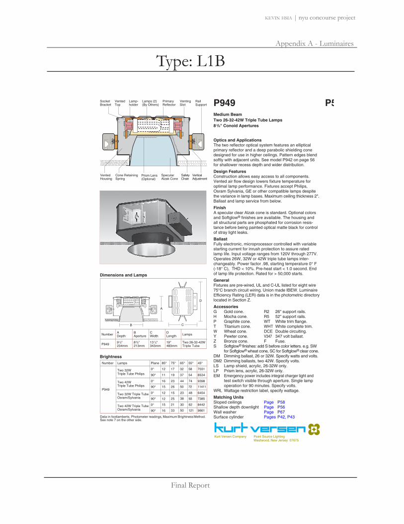
Final Report
Appendix A - Luminaires
kevin hsia | nyu concourse project
Dimensions and Lamps
Brightness
P949Medium BeamTwo 26-32-42W Triple Tube Lamps8 3/8" Conoid Apertures
Optics and ApplicationsThe two reflector optical system features an elliptical primary reflector and a deep parabolic shielding conedesigned for use in higher ceilings. Pattern edges blendsoftly with adjacent units. See model P942 on page 56for shallower recess depth and wider distribution.
Design FeaturesConstruction allows easy access to all components.Vented air flow design lowers fixture temperature for optimal lamp performance. Fixtures accept Philips, Osram Sylvania, GE or other compatible lamps despitethe variance in lamp bases. Maximum ceiling thickness 2".Ballast and lamp service from below.
FinishA specular clear Alzak cone is standard. Optional colorsand Softglow® finishes are available. The housing and all structural parts are phosphated for corrosion resis-tance before being painted optical matte black for controlof stray light leaks.
BallastFully electronic, microprocessor controlled with variablestarting current for inrush protection to assure rated lamp life. Input voltage ranges from 120V through 277V.Operates 26W, 32W or 42W triple tube lamps inter-changeably. Power factor .98, starting temperature 0° F (-18° C), THD < 10%. Pre-heat start < 1.0 second. End of lamp life protection. Rated for > 50,000 starts.
GeneralFixtures are pre-wired, UL and C-UL listed for eight wire75°C branch circuit wiring. Union made IBEW. LuminaireEfficiency Rating (LER) data is in the photometric directorylocated in Section Z.
AccessoriesG Gold cone. R2 26" support rails.H Mocha cone. R5 52" support rails.P Graphite cone. WT White trim flange.T Titanium cone. WHT White complete trim.W Wheat cone. DCE Double circuiting.Y Pewter cone. V347 347 volt ballast.Z Bronze cone. F Fuse.S Softglow® finishes: add S before color letters. e.g. SW
for Softglow® wheat cone, SC for Softglow® clear cone.DM Dimming ballast, 26 or 32W. Specify watts and volts.DM2 Dimming ballasts, two 42W. Specify volts.LS Lamp shield, acrylic, 26-32W only.LP Prism lens, acrylic, 26-32W only.EM Emergency power includes integral charger light and
test switch visible through aperture. Single lamp operation for 90 minutes. Specify volts.
WRL Wattage restriction label, specify wattage.
Matching UnitsSloped ceilings Page P58Shallow depth downlight Page P56Wall washer Page P67Surface cylinder Pages P42, P43
Kurt Versen Company Point Source LightingWestwood, New Jersey 07675
P57
Section P fronts_UG 11/13/02 7:57 PM Page 24Type: L1B

Final Report
Appendix A - Luminaires
kevin hsia | nyu concourse project
P949 Two 42W Philips Triple Tube Read Bottom Data
15° 25° 35°
61
44
33
20
14
56
40
30
19
13
3'
3'
4'
5'
6'
43
31
23
14
10
5'
6'
7'
9'
11'
23
16
12
8
5
8'
9'
11'
13'
16'
8'
9'
11'
12'
14'
7'
8'
9'
11'
14'
66
47
36
22
15
57
41
31
19
13
38
27
21
13
9
P949 Two 32W Philips Triple Tube Read Top Data
51
36
27
17
12
48
35
26
16
11
3'
3'
4'
5'
6'
35
25
19
12
8
5'
6'
7'
9'
11'
16
12
9
5
4
8'
9'
11'
13'
16'
6'
7'
8'
11'
13'
60
43
32
20
14
51
36
27
17
12
35
25
19
12
8
P57 P949Performance Datachart
Ceiling to FloorSingle Unit Initial Footcandles, 30" Work Plane Multiple Units Initial Footcandles, 30" Work Plane
Ceiling 80% Walls 50% Floor 20%
FC FC Diam Spacing RCR 1 RCR 3 RCR 8
Nadir
FC Diam FC Diam
Spacing is Maximum Over Work Plane
See notes 4, 5 and 6.Candlepower Distribution
Coefficients of Utilization
P949 Two 32W Triple Tube Philips P949 Two 32W Triple Tube Osram x .82P949 Two 42W Triple Tube Philips x .94 P949 Two 42W Triple Tube Osram x .80
Ceiling
Wall % 70 50 30 10 10 50 10 10 0
80% 70% 50% 30% 0
Zonal Cavity Method - Floor Reflectance 20%RCR
50
1
2
3
4
5
6
7
8
9
10
50
.49
.46
.44
.41
.39
.37
.35
.33
.31
.29
.48
.44
.41
.38
.35
.32
.30
.28
.26
.25
.47
.42
.38
.35
.32
.30
.27
.25
.24
.22
.46
.41
.37
.33
.30
.28
.25
.23
.22
.20
.47
.43
.40
.37
.35
.32
.30
.28
.26
.24
.45
.40
.36
.33
.30
.28
.25
.23
.22
.20
.45
.42
.39
.36
.34
.31
.29
.27
.26
.24
.43
.39
.36
.33
.30
.27
.25
.23
.22
.20
.43
.41
.38
.35
.33
.31
.29
.27
.25
.24
.42
.38
.35
.32
.30
.27
.25
.23
.21
.20
.40
.37
.34
.31
.29
.26
.24
.22
.21
.19
Candelas
1 Data on all charts calculated with a clear specular cone finish.2 Specular cone multipliers: Gold x .92, Wheat x .88, Pewter x .80,
Mocha x .78, Graphite x .78, Titanium x .78, Bronze x .75. 3 Softglow® cone multipliers: Clear x .93, Gold x .92, Wheat x .87,
Pewter x .78, Mocha x .78, Graphite x .77, Titanium x .77, Bronze x .76.4 Single unit Datachart pattern diameters are determined by the
number of degrees from each side of nadir. Therefore a 20° diameter represents a total 40° pattern width at the work plane 30" above the floor. Footcandle values are at the edge of that diameter.
5 Datachart spacing is rounded off to the nearest foot.6 Data by IES methods. Compact fluorescent data vary due to lamp
lumen differences, power input, burning position, ambient temperatureand ballast characteristics. A modification factor should be applied.
7 Brightness data from the Average Luminance Method are inaccuratefor small aperture downlights. They are theoretical calculations derived for large surfaces such as troffers. For a complete discussion refer to section Z brochure Z1.
Notes
Kurt Versen Company, Westwood, New Jersey
P949 Two 32W Triple Tube Philips Eff. 44% S/M 0° 1.08 S/M 90° 1.17
° Vertical Angles* Initial Lamp Lumens
360
540
720
900
1080
1260
1440
1620
1800
55°
35°
45°
75°
65°
85°
25°15°5°
90°0°
153916541686169616441461122010158013621091710000000
051015202530354045505560657075808590
4800*4800*°153915131455153914871377103076465428160179000000
0°
90°
200
400
600
800
1000
1200
1400
1600
1800
2000
55°
35°
45°
75°
65°
85°
25°15°5°
90°0°
18451946197220081941177515991392105647313423151200000
051015202530354045505560657075808590
6400*6400*°18451816169217491816172814391123892220471712500000
P949 Two 42W Triple Tube Osram Eff. 42% S/M 0° 1.15 S/M 90° 1.25
° Vertical Angles* Initial Lamp Lumens
0°
90°
P949 Two 32W Triple Tube Osram Sylvania Eff. 36% S/M 0° 1.06 S/M 90° 1.14
175
350
525
700
875
1050
1225
1400
1575
1750
55°
35°
45°
75°
65°
85°
25°15°5°
90°0°
16981797181318181771163512859837623681111810400000
05
1015202530354045505560657075808590
° Vertical Angles* Initial Lamp Lumens
6400*6400*°1698166715731625160914631113811652263621811400000
P949 Two 42W Triple Tube Osram Sylvania Eff. 35% S/M 0° 1.06 S/M 90° 1.14
140
280
420
560
700
840
980
1120
1260
1400
55°
35°
45°
75°
65°
85°
25°15°5°
90°0°
13041380139213961360125698775558528385148300000
05
1015202530354045505560657075808590
° Vertical Angles* Initial Lamp Lumens
4800*4800*°13041280120812481236112485562350120248148300000
0°
90°
0°
90°
Section P backs_UG 8/30/02 2:03 AM Page 24Type: L1B

Final Report
Appendix A - Luminaires
kevin hsia | nyu concourse project
P926 57/8"149mm
101/2"267mm
131/4"337mm
26W or 32WTriple Tube
LampsNumber ADepth*
BAperture
CWidth
DLength
93/4"248mm
P927 57/8"149mm
101/2"267mm
131/4"337mm
42WTriple Tube
101/4"260mm
Dimensions and Lamps
B
A
C
D
LockSocket
VentSlot
JunctionBox
VentedHousing
VentedTop
Ballast
VerticalAdjustment
Cone Retainer Spring
RailSupport (2)
Lamp(By Others)
SpecularAlzak Cone
SafetyChain
*Recess depth increases to 121/2" with EM and DM accessories.
P926 One 26W or 32W Triple Tube Lamp
P927 One 42W Triple Tube Lamp
Medium Beam5 7/8" Conoid Apertures
Optics and ApplicationsDistribution from a single vertically mounted triple tubelamp is for general lighting. Spacing to mounting heightratios range from .93 to 1.11 depending upon which lampis mounted. Use in corridors, entries, work stations oropen area lighting in low to medium height ceilings.
Design FeaturesThe two reflector optical system is protected by a rigidsteel housing which keeps the reflectors in proper relationship to each other. The twist and lock socket prevents the lamp from falling if it is not properlyengaged. It is a dependable fail-safe mechanism to prevent injury and litigation. Maximum ceiling thicknessis 2". Ballast and lamp service from below.
FinishSpecular clear Alzak cones are standard. Optional colors and Softglow® finishes are available. Housings and structural parts are painted optical matte black tosuppress stray light leaks. Steel parts are phosphate conditioned for corrosion resistance before painting.
BallastsFully electronic, microprocessor controlled with variablestarting current for inrush protection to assure rated lamp life. Input voltage ranges from 120V through 277V.Power factor .98, starting temperature 0° F (-18° C), THD< 10%. Pre-heat start < 1.0 second. End of lamp life protection. Rated for > 50,000 starts.
GeneralFixtures are pre-wired, UL and C-UL listed for eight wire75°C branch circuit wiring. Union made IBEW. LuminaireEfficiency Rating (LER) data is in the photometric directorylocated in Section Z.
AccessoriesG Gold cone. R2 26" support rails.H Mocha cone. R5 52" support rails.P Graphite cone. WT White trim flange.T Titanium cone. WHT White complete trim.W Wheat cone. V347 347 volt ballast.Y Pewter cone. F Fuse.Z Bronze cone.S Softglow® finishes: add S before color letters. e.g. SW
for Softglow® wheat cone, SC for Softglow® clear cone.DM Dimming ballast. Specify watts and volts.EM Emergency power includes integral charger light and
test switch visible through aperture. Single lamp operation for 90 minutes. Specify volts.
WRL Wattage restriction label, specify wattage.
Matching UnitsMedium wide beam Page P52Wall washers Pages P61, P62, P63
Kurt Versen Company Point Source LightingWestwood, New Jersey 07675
P51
Section P fronts_UG 11/13/02 7:55 PM Page 18Type: L1C

Final Report
Appendix A - Luminaires
kevin hsia | nyu concourse project
.56
.53
.51
.48
.45
.43
.40
.38
.36
.34
.55
.51
.47
.44
.41
.38
.35
.33
.31
.29
.54
.49
.45
.41
.38
.35
.32
.30
.28
.26
.53
.47
.43
.39
.35
.33
.30
.28
.26
.24
.54
.50
.47
.43
.40
.38
.35
.33
.31
.29
.52
.47
.42
.38
.35
.32
.30
.28
.26
.24
.52
.48
.45
.42
.39
.37
.34
.32
.30
.29
.50
.46
.42
.38
.35
.32
.30
.28
.26
.24
.50
.47
.44
.41
.39
.36
.34
.32
.30
.28
.49
.45
.41
.38
.35
.32
.30
.27
.26
.24
.46
.43
.39
.36
.34
.31
.29
.27
.25
.23
.57
.54
.51
.48
.46
.43
.41
.39
.37
.35
.56
.52
.48
.44
.41
.38
.36
.34
.31
.30
.55
.50
.45
.41
.38
.35
.33
.30
.28
.26
.53
.48
.43
.39
.36
.33
.30
.28
.26
.24
.55
.51
.47
.44
.41
.38
.35
.33
.31
.29
.52
.47
.43
.39
.36
.33
.30
.28
.26
.24
.53
.49
.46
.43
.40
.37
.35
.33
.31
.29
.51
.46
.42
.38
.35
.33
.30
.28
.26
.24
.51
.48
.45
.42
.39
.36
.34
.32
.30
.28
.49
.45
.41
.38
.35
.32
.30
.28
.26
.24
.47
.43
.40
.37
.34
.31
.29
.27
.25
.23
Candlepower Distribution Coefficients of Utilization
P926 32W Triple Tube Osram Eff. 50% S/M .95
120
240
360
480
600
720
840
960
1080
1200
P926 One 32W Triple Tube Osram SylvaniaP926 One 32W Triple Tube Philips x .98
P927 42W Triple Tube Osram Eff. 48% S/M .93
140
280
420
560
700
840
980
1120
1260
1400
P 42W
P927 One 42W Triple Tube Osram SylvaniaP927 One 42W Triple Tube Philips x .89
Ceiling
Wall % 70 50 30 10 10 50 10 10 0
80% 70% 50% 30% 0
Zonal Cavity Method - Floor Reflectance 20%RCR
50
1
2
3
4
5
6
7
8
9
10
50
Ceiling
Wall % 70 50 30 10 10 50 10 10 0
80% 70% 50% 30% 0
Zonal Cavity Method - Floor Reflectance 20%RCR
50
1
2
3
4
5
6
7
8
9
10
50
O 42W
110411881211115410639197475834412532380000000
1412140313281176109295878961148735575100000000
05
1015202530354045505560657075808590
55°
35°
45°
75°
65°
85°
25°15°5°
55°
35°
45°
75°
65°
85°
25°15°5°
9381021105510209568376674673211731660000000
2400*P 32WO 32W
Candelas
11341152110910239167896254603532121970000000
05
1015202530354045505560657075808590
° Vertical Angles* Initial Lamp Lumens
2400*°
° Vertical Angles* Initial Lamp Lumens
3200*3200*°
P927 42W Triple Tube Philips Eff. 44% S/M 1.07
120
240
360
480
600
720
840
960
1080
1200
55°
35°
45°
75°
65°
85°
25°15°5°
P926 32W Triple Tube Philips Eff. 50% S/M 1.11
110
220
330
440
550
660
770
880
990
1100
55°
35°
45°
75°
65°
85°
25°15°5°
Data in footlamberts. Photometer readings, Maximum Brightness Method. See note 7.
Brightness
34
45
45
62
91
82
151
208
203
Number Lamps 85° 75° 65° 55°
P926
P927
32W Philips Triple Tube
42W Osram Sylvania Triple Tube
42W Philips Triple Tube
10 33 66 150
12
14
15
10756
17796
14468
45°
12837
1 Data on all charts calculated with a clear specular cone finish.2 Specular cone multipliers: Wheat x .84, Pewter x .79,
Mocha x .78, Graphite x .75, Titanium x .75, Bronze x .72.3 Softglow® cone multipliers: Wheat x .71, Mocha x .68,
4 Single unit Datachart pattern diameters are determined by thenumber of degrees from each side of nadir. Therefore a 20° dia-meter represents a total 40° pattern width at the work plane 30" above the floor. Footcandle values are at the edge of that diameter.
5 Datachart spacing is rounded off to the nearest foot.6 Data by IES methods. Compact fluorescent data vary due to
lamp differences, power input, burning position, ambient temp-erature and ballast characteristics. Apply a modification factor.
7 Brightness data from the Average Luminance Method are inaccurate for small aperture downlights. They are theoreticalcalculations derived for large surfaces such as troffers. For acomplete discussion refer to section Z brochure Z1.
Notes
Kurt Versen Company, Westwood, New Jersey
See notes 4, 5 and 6.
P927 One 42W Osram Triple Tube Read Bottom Data
10° 20° 30°
47
33
25
16
11
42
30
23
14
10
2'
2'
3'
3'
4'
30
21
16
10
7
4'
5'
5'
7'
8'
17
12
9
6
4
6'
8'
9'
11'
13'
8'
9'
10'
12'
14'
5'
6'
7'
9'
11'
66
47
36
22
15
56
40
30
19
13
39
28
21
13
9
P926 One 32W Osram Triple Tube Read Top Data
37
27
20
13
9
35
25
19
12
8
2'
2'
3'
3'
4'
25
18
14
8
6
4'
5'
5'
7'
8'
13
10
7
4
3
6'
8'
9'
11'
13'
5'
6'
7'
9'
11'
49
35
26
17
11
42
30
23
14
10
30
21
16
10
7
P51 P926 P927Performance Datachart
Ceiling to FloorSingle Unit Initial Footcandles, 30" Work Plane Multiple Units Initial Footcandles, 30" Work Plane
Ceiling 80% Walls 50% Floor 20%
FC FC Diam Spacing RCR 1 RCR 3 RCR 8
Nadir
FC Diam FC Diam
Spacing is Maximum Over Work Plane
Section P backs_UG 8/30/02 2:03 AM Page 18Type: L1C

Final Report
Appendix A - Luminaires
kevin hsia | nyu concourse project
SELUX Corp. © 2006TEL: (845) 691-7723FAX: (845) 691-6749
www.selux.com/usaM1RA1-01 (v5.0)
Union Made Affiliated with IBEW Local 363
M100 Recessed Linear Fluorescent AsymmetricalFlanged Extrusion
Options (refer to separate data sheets for ordering codes and details)
_ _ _ _ _ _ _ _
Project: Type: Qty.
In a continuing effort to offer the best product possible, we reserve the right to change, without notice, specifications or materials that in our opinion will not alterthe function of the product. Specification sheets found at www.selux.com/usa are the most recent versions and supercede all other printed or electronic versions.
4" (100mm)
4" (1
00m
m)
M1RA1M1RA2
413/16"(122mm)
Scale
= 1
: 4
56
1
2
4
3
117 1098
12
Suspension Clips (SH) Rotating Crossbars (RC)Pre-installed Rod (TS) Perimeter Mount (PM)
Mounting Diagrams
4"(1
00m
m)
4"(1
00m
m)
70
41 /2"
(114
mm
)
4"(1
00m
m)
Fixture Series Lamp Type Nominal Length Finish Options
M1RA1M100 RecessedAsymmetricalContinuous Flange(Flanged Extrusion/Flanged Endcaps)
M1RA2M100 RecessedAsymmetricalFlush End(Flanged Extrusion/ Flangeless Endcaps)
004 4 foot
008 8 foot
012 12 foot
For actual lengths
see following page. For
other lengths, configura-
tions indicate nominal
length rounded to the
next highest foot. Factory
will supply layout draw-
ings. Individual fixtures
cannot be field joined.
120
277
347
WH White
BK Black
SV Silver
SP SpecifyRAL#
Shielding
AMP Asymmetric SilkySpecular Louver
SD Satine Lens
1T5 & T5HO lamps only, consult factory for other lamps. 2Must be low profile ballasts (11/2" W x 13/16" H); consult factory for details. 3Consult factory for details.
VoltageMounting
SH Suspension Clips
TS 1" Studs (factory installed)
RC Rotating Crossbars
PM Perimeter Mount
1T5 F28T5
1T5HO F54T5HOTB Lengths to Fit 2’ Grid
T-Bar Ceiling System1
(qty.)EM Stand-by Battery Pack2
(prefix quantity, i.e. - 5EM)
FS Single FusingDM Dimming2 (specify system)DMA Digital Addressable Dimming2
FW Flex Whip (standard)FW1 Flex Whip (dimming)DL Suitable for Damp LocationsCCEA Chicago PlenumDownlights (See MR16 spec
sheets, pp.98-99)
1. Housing - Continuous, 6063-T5extruded aluminum profile up to 16feet long. Joined with ConnectorPlus Joining System for ease ofinstallation and to assure a uniformappearance.
2. Ballast - Electronic, high powerfactor, class "P", type "A" soundrating. Specify 120v, 277v, or347v. Ballast is factory pre-wiredwith leads to one end of fixture.Consult factory for ballast options.
3. Gear Tray - Extruded aluminum,with white painted finish.Gear tray installed as a completeelectrical unit and is held in placewith knurled dress nuts. It is fullyaccessible from below ceiling.
4. Flange - 1/2" (12mm) wideflange runs full lengths of bothsides and is part of the mainextruded body. Specify continuousflange (M1RA1) or flush end(M1RA2).
5. Lamps - As noted (by others).Other lamp lengths or wattagesavailable, consult factory.
6. Shielding - Louvers offer excellent glare control in longitudinal, lateral, and all diagonal planes. High quality aluminum louvers and acrylicshielding allow true freedom oflayout for contemporary modernspaces.
7. Spring steel suspension clips -Supplied two places, located nominally every 4 ft. Support wiresSupplied and installed by others.
8. Pre-installed 1" 1/4-20 Stud -Attached to fixture every nominal4 feet.
9. Coupling and Threaded Rodto Structure - Supplied andinstalled by others.
10. Rotating Crossbars - For inac-cessible ceilings, adjustable for ceil-ing thicknesses from 1/4" to 2".Support required nominally every 4’.
11. Steel Wall Bracket and 1/4-20rod supplied nominally every 4 ft.(Fasteners to wall and wall anchorsby others)
12. Aluminum Wall Bracket -Secured to wall (fasteners and wallanchors by others) and runs entirelength of fixture. Also supplied forwidth of fixtures when supplied withcontinuous flange. Allows for 1/8"gap between flange and wall to cre-ate shadow line allowing forunevenness of wall.
Interior Luminaire Finish -Standard interior colors are White(WH), Black (BK) and Silver SV).RAL colors (SP) are available,please specify RAL#.
Scale = 1 : 8
LampType
Shielding Mounting NominalLength
FixtureSeries
_ _ _ _ _ _ _
Finish Voltage
Type: L2A

Final Report
Appendix A - Luminaires
kevin hsia | nyu concourse project
M100 Recessed Linear Fluorescent AsymmetricalFlanged Extrusion
M1RA1 and M1RA2 Layout Dimensions
For other lengths, lamping, continuous runs or configurations please specify overall length (in feet), accessories desired and sketch/drawing ofconfiguration. SELUX will detail project drawings upon order and supply submittal drawings for approval. Individual fixtures cannot be fieldjoined. If you have any questions please contact SELUX customer service or applications engineering for assistance (1-800-SELUX-CS).
M1RA1/M1RA2 Recessed - nominal 12 foot individual
M1RA1 Recessed - T-Bar Length - nominal 12 foot individual
M1RA1/M1RA2 Recessed - nominal 8 foot individual
M1RA1 Recessed - T-Bar Length - nominal 8 foot individual
M1RA1/M1RA2 Recessed - nominal 4 foot individual
M1RA1 Recessed - T-Bar Length - nominal 4 foot individual
Typical Side View Including Endplates
Outside Flange (M1RA1)
Outside Flange (M1RA1)
Outside Flange (M1RA1)
4" (100mm)
71
In a continuing effort to offer the best productpossible, we reserve the right to change, withoutnotice, specifications or materials that in ouropinion will not alter the function of the product.Specification sheets found at www.selux.com/usaare the most recent versions and supercede allother printed or electronic versions.
SELUX Corp. © 2006PO Box 1060, 5 Lumen Lane / Highland, NY 12528TEL: (845) 691-7723 / FAX: (845) 691-6749E-mail: [email protected] / Web Site: www.selux.com/usaM1RA1-02 (02/06)
12’ CL to CL of T-Bar115/16" (49mm) Blank Cover 115/16" (49mm)
Blank Cover
2’ typical
8’ CL to CL of T-Bar13/16" (29mm) Blank Cover 13/16" (29mm)
Blank Cover
2’ typical
4’ CL to CL of T-Bar
2’ typical
Direction of illumination
Direction of illumination
Direction of illumination
Direction of illumination
Direction of illumination
Direction of illumination
Feed End
Feed End
Feed End
Feed End
Feed End
Feed End
Flush End (M1RA2)
Continuous Flange (M1RA1)
Outside Flange 413/16" (122mm)
Housing 6" (152mm)
49.20" (1250mm)
97.24" (2470mm)
145.28" (3690mm)
Outside FlangeM1RA1
T8 (1 lamp)T5 (1 or 2 lamp)
48.33" (1228mm)
96.37" (2448mm)
144.41" (3668mm)
Including Endplates
47.91" (1216mm)
95.91" (2436mm)
143.91" (3655mm)
Outside FlangeM1RA1 - TB
47.03" (1195mm)
95.03" (2414mm)
143.03" (3633mm)
Including EndplatesM1RA1/M1RA2 - TB
47.58" (1209mm)
94.00" (2388mm)
140.41" (3567mm)
Outside Flange
4 foot individual8 foot individual
12 foot individual
Including EndplatesM1RA1/M1RA2 M1RA1 M1RA1/M1RA2
Suspensions supplied spaced nominally every 4 feet. Fixture supplied with 7/8 knockout located 23/16" from end in top of fixture.
46.81" (1186mm)
93.21" (2365mm)
139.65" (3544mm)
23/16" (56mm) Feed
407/16" (1027mm)63/16"(157mm)
63/16" (157mm)467/16" (1179mm) 407/16" (1027mm)
Type: L2A

Final Report
Appendix A - Luminaires
kevin hsia | nyu concourse project
SELUX Corp. © 2006TEL: (845) 691-7723FAX: (845) 691-6749
www.selux.com/usaM1B1S-01 (v5.0)
Union Made Affiliated
with IBEW Local 363
M100 Super Recessed Linear FluorescentFlanged Extrusion - STAGGERED LAMPS
In a continuing effort to offer the best product possible, we reserve the right to change, without notice, specifications or materials that in our opinion will not alterthe function of the product. Specification sheets found at www.selux.com/usa are the most recent versions and supercede all other printed or electronic versions.
Fixture Series Lamp Type Nominal Length Finish Options
M1B1SM100 Super RecessedContinuous Flange(Flanged Extrusion/Flanged Endcaps)Staggered Lamps
M1B2SM100 Super RecessedFlush End(Flanged Extrusion/ Flangeless Endcaps)Staggered Lamps
008 8 foot
012 12 foot
For actual lengths
see following page. For
other lengths, configura-
tions indicate nominal
length rounded to the
next highest foot. Factory
will supply layout draw-
ings. Individual fixtures
cannot be field joined.
120
277
347
WH White
BK Black
SV Silver
SP SpecifyRAL#
Lower Shielding
SA Specular ParabolicMA Matte ParabolicMP Silky Specular ParabolicPL Matte Perforated
ParabolicSD Satine LensOD Extra Diffuse LensX None
1Must be low profile ballasts (11/2" W x 13/16" H); consult factory for details. 2Consult factory for details.
VoltageMounting
SH Suspension Clips
TS 1" Studs (factory installed)
RC Rotating Crossbars
PM Perimeter Mount
1. Housing - Continuous, 6063-T5 extruded aluminum profile up to 16 feet long. Joinedwith Connector Plus JoiningSystem for ease of installation andto assure a uniform appearance.
2. Ballast - Electronic, high powerfactor, class "P", type "A" soundrating. Specify 120v, 277v, or347v. Ballast is factory pre-wiredwith leads to one end of fixture.Consult factory for ballast options.
3. Gear Tray - Die formed geartray with integral factory presetsliding covers to fill extrusion withlight, with a matt white finish foreven illumination. Geartrayinstalls as complete electrical unitand is held in place with knurleddress nuts. It is fully accessiblefrom below ceiling.
4. Flange - 1/2" (12mm) wideflange runs full lengths of bothsides and is part of the mainextruded body. Specify continu-ous flange (M1B1S) or flush end(M1B2S).
5. Lamps - As noted (by others).Other lamp lengths or wattagesavailable, consult factory.
6. Shielding - Louvers offer excel-lent glare control in longitudinal,lateral, and all diagonal planes.High quality aluminum louvers andacrylic shielding allow true free-dom of layout for today’s modernspaces. See page 8 for details.
7. Spring Steel SuspensionClips - Supplied two places,located nominally every 4 ft.Support wires supplied andinstalled by others.
8. Pre-installed 1" 1/4-20 Stud -Attached to fixture every nominal4 feet.
9. Coupling and Threaded Rodto Structure - Supplied andinstalled by others.
10. Rotating Crossbar - Forinaccessible ceilings, adjustablefor ceiling thicknesses from 1/4" to2". Support required nominally every4 feet.
11. Steel Wall Bracket and 1/4-20 Rod - Supplied nominallyevery 4 ft. (Fasteners to wall andwall anchors by others)
12. Aluminum Wall Bracket -Secured to wall (fasteners andwall anchors by others) and runsentire length of fixture. Also sup-plied for width of fixtures whensupplied with continuous flange.Allows for 1/8" gap betweenflange and wall to create shadowline allowing for unevenness ofwall.
Interior Luminaire Finish -Standard interior colors are White (WH), Black (BK) andSilver (SV). RAL colors (SP) areavailable, please specify RAL#.
TB Lengths to Fit 2’ GridT-Bar Ceiling System
(qty.)EM Stand-by Battery Pack1
(prefix quantity, i.e. - 5EM)
FS Single FusingDM Dimming1 (specify system)DMA Digital Addressable Dimming1
FW Flex Whip (standard)FW1 Flex Whip (dimming)Track Eutrac Standard2
DL Suitable for Damp LocationsCCEA Chicago PlenumDownlights (See MR16 spec
sheets, pp.98-99)
11
6"(1
52m
m)
7 10
12
Suspension Clips (SH) Rotating Crossbars (RC)Pre-installed Rod (TS) Perimeter Mount (PM)
Mounting Diagrams
6"(1
52m
m)
6"(1
52m
m)
1T5 F28T5
1T5HO F54T5HO
2T5 (2x)F28/T5
60
4" (100mm)
6" (1
52m
m)
M1B1SM1B2S
Scale
= 1
: 4
5
1
2
4
3
65" (127mm)
61 /2"
(164
mm
)
Scale = 1 : 8 TrackTrack insert including trackavailable for all configurations,consult factory for details.
8
9
Options (refer to separate data sheets for ordering codes and details)
_ _ _ _ _ _ _ _
Project: Type: Qty:
LampType
LowerShielding
Mounting NominalLength
UpperShielding
FixtureSeries
_ _ _ _ _ _ _
Finish Voltage
Upper Shielding
SD Satine LensOD Extra Diffuse LensX None
Type: L2B

Final Report
Appendix A - Luminaires
kevin hsia | nyu concourse project
61
M100 Super Recessed Linear FluorescentFlanged Extrusion - STAGGERED LAMPS
M1B1S/M1B2S (Single Staggered Lamps) Standard Layout Dimensions
M1B1S (Single Staggered Lamps) T-Bar Layout Dimensions (option - TB)
M1B1S-02 (02/06)In a continuing effort to offer the best product possible, we reserve the right to change, without notice, specifications or materials that in our opinion will not alterthe function of the product. Specification sheets found at www.selux.com/usa are the most recent versions and supercede all other printed or electronic versions.
Minimal socket shadows may be visible at certain angles. Refer to page 8 for more information.
Nominal 8 foot IndividualSide View
BottomView
Equal Equal951/8" (2416mm) Including Endcaps
96" (2388mm) Outside Flange (M1B1S)
Nominal 12 foot IndividualSide View
BottomView
Equal Equal Equal
1431/8" (3635mm) Including Endcaps
144" (3658mm) Outside Flange (M1B1S)
4" (102mm) Overlap
Side View
Bottom View
8’ CL to CL of T-Bar
Side View
Bottom View
12’ CL to CL of T-Bar
Nominal 8 foot Individual
Nominal 12 foot Individual
2’ Typical
2’ Typical 47/16" (112mm) Overlap
4" (100mm)
6" (152mm) Housing
413/16" (122mm) Outside Flange
413/16" (122mm) Outside Flange
9/16" REF
6" (152mm)
13/4" REF
315/16" (100mm) Housing
Lamps are spaced with 4" to 6" overlap to completely illuminate luminaire and elimi-nate socket shadows. Factory will supply approval drawings for other lengths usingcombinations of 21W & 28W T5 lamps or 39W & 54W T5HO lamps.
Staggered Lamps Principle
M1B1S/M1B2S (Double Staggered Lamps) Layout Dimensions - Factory will provide submittal drawings. See chart on page 7 for lengths under 22 ft.
For other lengths, lamping, continuous runs or configurations please specify overall length (in feet), accessories desired and sketch/drawing ofconfiguration. SELUX will detail project drawings upon order and supply submittal drawings for approval. Individual fixtures cannot be fieldjoined. If you have any questions please contact SELUX customer service or applications engineering for assistance (1-800-SELUX-CS).
Suspensions supplied spaced nominally every 4 feet. Fixture supplied with 7/8 knockout located 23/16" from end in top of fixture.See chart on page 6 for optimal custom lengths under 18 ft. Any length over 18 ft. possible, see below.
25/16" (60mm)Blank Cover
23/16" (56mm) Feed
63/16"(157mm)
63/16" (157mm)Equal
Equal63/16"(157mm)
63/16" (157mm)
47/16" (112mm) Overlap
23/16" (56mm) Feed
23/16" (56mm) Feed
23/16" (56mm) Feed
95" (2414mm) Including Endcaps
9515/16" (2436mm) Outside Flange
14315/16" (3655mm) Outside Flange
143" (3632mm) Including Endcaps
4" (102mm) Overlap
23/8" (60mm)Blank Cover
Type: L2B

Final Report
Appendix A - Luminaires
kevin hsia | nyu concourse project
Questions to Ask
litecontrol.com
Type:Project:
litecontrol.com
FIXTURE SUPPORT RAIL. Extruded white aluminum, wall-mounted rail provides continuous support and true alignment of fixtures and components. Rail is designed to provide a reveal at the wall to compensate for irregularities in wall construction. Galvanized splines are included for continuous alignment. FIXTURE HOUSING. Die-formed and welded steel. Plenum cover/wall bracket is a one-piece assembly of 20-gauge steel and heavy-gauge steel brackets with leveling screws to provide adjustment. Brackets are spaced approximately every two feet for 2-, 4-, and 8-foot fixtures, and 1 1/2 feet for 3-foot and 6-foot fixtures. Plenum cover has a continuous hook-and-lock feature for quick installation.REFLECTOR. 2000 curved reflector is die-formed specular hammertone aluminum, precisely shaped for maximum downward light projection. Straight reflector portions are steel, finished in high-reflectance white for uniform light distribution. 2000PR uses a larger parabolic reflector (PR), die-formed, hammertone, low-iridescence semi-specular aluminum, precisely shaped for maximum downward light projection. It is shielded from all viewing angles from 0° to 60° below horizontal. Straight reflector portions are steel, finished in high-reflectance white for uniform light distribution.CEILING TRIM/LUMINANCE CONTROL DEFLECTOR. Extruded aluminum with internal aligner splines. LCD shields lamps from direct view and eliminates socket shadows on wall. Paint finish is Matte White (CWM) baked enamel.LAMPING. Available in one-lamp T5, T5HO, or T8, or one-lamp twin-tube compact fluorescent.BALLAST. Electronic Ballast (ELB - for T8 or BX lamping) or Low-profile Electronic Ballast (LP/ELB - for T5 or T5HO lamping), high power factor, thermally protected Class P, Sound Rated A, manufactured by a UL Listed manufacturer, as available, determined by Litecontrol. Ballasts with a voltage range of 120 to 277 will be used when fixture configuration and ballast availability allow. The minimum number of ballasts will be used.CEILING TYPE. Compatible with most types of ceiling systems, including grid and plaster. Fixture system must be installed prior to installation of ceiling. Finish of wall should extend 13" above finished ceiling height. See Wall/Slot-2000 Pre-Installation Manual for specific ceiling type details.CERTIFICATION. Fixture and electrical components shall be UL and/or CUL Listed and shall bear the I.B.E.W., A.F. of L. label.
Note: Litecontrol reserves the right to change specifications without notice for product development and improvement.
2014T8-CWM-ELB-1CWQ-PR-120 is a typical catalog number for a 1-lamp (1 lamp in cross-section), 4-foot long T8 fixture, Matte White finish, electronic ballast, pre-wired with single-circuit branch-wiring, parabolic reflector, 120 volts.
Specifications
Ordering guide
1. 120 or 277 volt? 2. Row information, including desired fixture lengths? 3. Verify ceiling type? 4. Other options?
Cross-section lamping
2000
1-T8 1-BX39 or 40
2000PR
1-T8 1-T5 or T5HO 1-BX39 or 40
1-T5 or T5H O
Wall/Slot®-2000Wall/Slot®-2000PR2000 or 2000PR Recessed Perimeter
9"(229)
3/8"(10)
13 1/2"(343)
3 3/4"(95)
9"(229)
Wall/Slot-2000
9"(229)
3/8"(10)
13 1/2"(343)
3 3/4"(95)
9"(229)
Wall/Slot-2000PR
Product, lamping, & length
20 1 4 T8 -
Series
20
Lamp Count
1 2 1 2 1 2 4 2 4
seenotes
Nominal Length(ft)
2,3,4 6,8 3,4 6,8 2 4 8 3 6
Lamp Type
T8
T5HOT5BX40
BX39
Options
CWM - ELB - PR - 120
Finish
CWM(Matte White) is standard
Ballast
ELBis std. for T8 or BXLP/ELB is std. for T5 or T5HO
DA/ELBHEL/ELBECO/ELB
see Ballast options
Other options
EFFPRSDS
see Other options
Volts
120 277
Type: L3

Final Report
Appendix A - Luminaires
kevin hsia | nyu concourse project
Type: L3

Final Report
Appendix A - Luminaires
kevin hsia | nyu concourse project
100 HAWKS AVENUE HANSON MA 02341 781 294 0100 FAX 781 293 2849 [email protected] www.litecontrol.com
PHOTOMETRIC DATA: Wall/Slot-2000
RCR
2014T8-120 70% wall reflectanceLitecontrol Certified Test Report #14711001
CANDLEPOWER SUMMARY
Floor Cavity Reflectance .20
ANGLE 0 45 90 135 180 OUTPUTLUMENS90 0 0 1 1 1
85 6 7 14 15 13 1480 16 16 41 29 2775 25 29 71 46 41 4970 36 43 103 64 5765 49 87 133 82 73 10360 85 187 164 102 9055 166 305 193 118 108 17650 301 413 220 129 12745 424 511 245 142 139 22840 543 589 267 155 14735 642 604 287 170 156 22530 701 580 303 189 16925 667 520 318 212 185 16920 582 457 330 235 20715 482 390 339 265 236 9710 383 370 345 297 2725 372 368 349 328 315 330 349 349 349 349 349
RCC 80 70 50 30 10 0RW 70 50 30 10 70 50 30 10 50 30 10 50 30 10 50 30 10 0
0 .45 .45 .45 .45 .44 .44 .44 .44 .42 .42 .42 .40 .40 .40 .38 .38 .38 .381 .42 .40 .39 .37 .41 .39 .38 .37 .38 .37 .36 .36 .35 .35 .35 .34 .33 .332 .38 .36 .33 .31 .37 .35 .33 .31 .33 .32 .30 .32 .31 .30 .31 .30 .29 .283 .35 .32 .29 .27 .34 .31 .29 .27 .30 .28 .26 .29 .27 .26 .28 .27 .25 .244 .32 .28 .25 .23 .32 .28 .25 .23 .27 .24 .22 .26 .24 .22 .25 .23 .22 .215 .30 .25 .22 .19 .29 .25 .22 .19 .24 .21 .19 .23 .21 .19 .22 .20 .19 .186 .27 .22 .19 .17 .27 .22 .19 .17 .21 .19 .17 .21 .18 .17 .20 .18 .16 .167 .25 .20 .17 .15 .24 .20 .17 .15 .19 .16 .15 .19 .16 .14 .18 .16 .14 .148 .23 .18 .15 .13 .22 .18 .15 .13 .17 .14 .12 .17 .14 .12 .16 .14 .12 .129 .21 .16 .13 .11 .21 .16 .13 .11 .15 .13 .11 .15 .12 .11 .15 .12 .10 .10
10 .19 .15 .11 .09 .19 .14 .11 .09 .14 .11 .09 .14 .11 .09 .13 .11 .09 .09
RCR
2014T8-120 50% wall reflectanceLitecontrol Certified Test Report #14711000
CANDLEPOWER SUMMARY
Floor Cavity Reflectance .20
% % ZONE LUMENS LAMP LUMINAIRE
180-90° 0 0.0 0.090-0° 1045 36.05 100180-0° 1045 36.05 100
ZONAL LUMEN SUMMARY
ANGLE 0 45 90 135 180 OUTPUTLUMENS90 0 1 1 2 1
85 4 5 13 12 10 1280 13 14 38 24 2175 21 24 68 39 33 4470 30 36 98 56 4765 41 79 129 70 61 9560 73 182 159 84 7555 150 304 187 93 88 16650 286 423 214 102 10145 418 528 237 113 108 22140 551 602 260 126 11435 656 615 279 143 124 22030 709 593 296 163 13725 676 532 310 187 156 16520 595 466 321 215 18115 490 393 330 248 214 9510 385 365 336 283 2565 367 361 340 319 305 320 308 308 308 308 308
RCC 80 70 50 30 10 0RW 70 50 30 10 70 50 30 10 50 30 10 50 30 10 50 30 10 0
0 .43 .43 .43 .43 .42 .42 .42 .42 .40 .40 .40 .38 .38 .38 .37 .37 .37 .361 .40 .38 .37 .36 .39 .38 .36 .35 .36 .35 .34 .35 .34 .33 .33 .33 .32 .322 .37 .34 .32 .30 .36 .34 .32 .30 .32 .31 .29 .31 .30 .29 .30 .29 .28 .273 .34 .30 .28 .26 .33 .30 .28 .26 .29 .27 .25 .28 .26 .25 .27 .26 .24 .244 .31 .27 .24 .22 .30 .27 .24 .22 .26 .24 .22 .25 .23 .21 .24 .23 .21 .205 .29 .24 .21 .19 .28 .24 .21 .19 .23 .21 .19 .22 .20 .18 .22 .20 .18 .186 .26 .22 .19 .16 .26 .21 .18 .16 .21 .18 .16 .20 .18 .16 .20 .17 .16 .157 .24 .19 .16 .14 .24 .19 .16 .14 .19 .16 .14 .18 .16 .14 .18 .15 .14 .138 .22 .17 .14 .12 .22 .17 .14 .12 .17 .14 .12 .16 .14 .12 .16 .14 .12 .119 .20 .16 .13 .10 .20 .15 .12 .10 .15 .12 .10 .14 .12 .10 .14 .12 .10 .10
10 .19 .14 .11 .09 .18 .14 .11 .09 .13 .11 .09 .13 .11 .09 .13 .11 .09 .08
ANGLE 0° 45° 90° 135° 180°
45° 622 785 351 167 16055° 275 558 342 171 16265° 102 196 319 174 15175° 83 97 274 160 13585° 51 61 160 144 126
LUMINANCE SUMMARY (fL)
% % ZONE LUMENS LAMP LUMINAIRE
180-90° 0 0.0 0.090-0° 1090 37.61 100180-0° 1090 37.61 100
ZONAL LUMEN SUMMARY
ANGLE 0° 45° 90° 135° 180°
45° 630 759 362 210 20655° 304 559 353 216 19865° 123 216 330 205 18375° 103 118 289 186 16785° 69 80 174 181 151
LUMINANCE SUMMARY (fL)
90˚
150˚180˚
0˚
60˚
30˚
Across45Along
800
1200
RCR
2014T5HO 50% wall reflectanceLitecontrol Certified Test Report #14716000
CANDLEPOWER SUMMARY
Floor Cavity Reflectance .20
% % ZONE LUMENS LAMP LUMINAIRE
180-90° 0 0.0 0.090-0° 1706 34.14 100.00180-0 ° 1706 34.14 100.00
ZONAL LUMEN SUMMARY
ANGLE 0 45 90 135 180 OUTPUTLUMENS90 0 2 1 0 0
85 7 12 20 11 7 1680 25 28 64 25 2275 39 44 109 48 38 7070 57 94 162 76 5965 81 174 210 99 82 15860 176 349 259 131 10555 283 447 307 159 130 27050 479 573 352 181 15445 568 706 392 205 182 34040 698 863 428 228 20135 841 1015 459 252 220 35230 1019 1038 486 283 24225 1139 1075 507 314 265 28820 1128 968 522 352 30015 1033 722 539 394 345 16610 679 620 545 439 3975 578 578 551 491 462 520 546 546 546 546 546
RCC 80 70 50 30 10 0RW 70 50 30 10 70 50 30 10 50 30 10 50 30 10 50 30 10 0
0 .41 .41 .41 .41 .40 .40 .40 .40 .38 .38 .38 .36 .36 .36 .35 .35 .35 .341 .38 .36 .35 .34 .37 .36 .35 .34 .34 .33 .32 .33 .32 .31 .32 .31 .31 .302 .35 .32 .30 .29 .34 .32 .30 .28 .31 .29 .28 .30 .28 .27 .29 .28 .27 .263 .32 .29 .27 .25 .31 .28 .26 .24 .27 .26 .24 .27 .25 .24 .26 .24 .23 .224 .30 .26 .23 .21 .29 .25 .23 .21 .25 .22 .21 .24 .22 .20 .23 .22 .20 .205 .27 .23 .20 .18 .26 .23 .20 .18 .22 .20 .18 .21 .19 .18 .21 .19 .17 .176 .25 .21 .18 .16 .24 .20 .18 .16 .20 .17 .16 .19 .17 .15 .19 .17 .15 .157 .23 .19 .16 .14 .22 .18 .16 .14 .18 .15 .14 .17 .15 .13 .17 .15 .13 .138 .21 .17 .14 .12 .21 .16 .14 .12 .16 .13 .12 .16 .13 .12 .15 .13 .12 .119 .19 .15 .12 .10 .19 .15 .12 .10 .14 .12 .10 .14 .12 .10 .14 .11 .10 .09
10 .18 .13 .11 .09 .18 .13 .11 .09 .13 .11 .09 .13 .10 .09 .12 .10 .09 .08
ANGLE 0° 45° 90° 135° 180°
45° 845 1050 580 304 270 55° 519 819 560 291 23865° 200 434 520 246 20575° 159 178 440 196 15485° 82 139 245 131 82
LUMINANCE SUMMARY (fL)
90˚
150˚180˚
0˚
60˚
30˚
Across45Along
1600
2400
RCR
2024BX40 50% wall reflectanceLitecontrol Certified Test Report #14720000
CANDLEPOWER SUMMARY
Floor Cavity Reflectance .20
% % ZONE LUMENS LAMP LUMINAIRE
180-90° 0 0.0 0.090-0° 2204 35.00 100.00180-0° 2204 35.00 100.00
ZONAL LUMEN SUMMARY
ANGLE 0 45 90 135 180 OUTPUTLUMENS90 3 1 2 3 3
85 14 8 27 8 8 1980 25 34 85 36 2575 47 57 149 63 47 8970 68 111 214 96 7465 96 200 279 129 96 19860 195 398 341 168 12855 305 570 409 205 161 34150 523 797 465 234 20045 704 1005 523 264 233 44640 972 1238 570 296 25535 1193 1361 613 333 271 46430 1448 1394 650 374 31025 1548 1257 680 419 348 37420 1448 1058 704 474 39815 1129 901 723 530 457 21010 884 791 734 597 5345 769 765 738 667 616 690 729 729 729 729 729
RCC 80 70 50 30 10 0RW 70 50 30 10 70 50 30 10 50 30 10 50 30 10 50 30 10 0
0 .42 .42 .42 .42 .41 .41 .41 .41 .39 .39 .39 .37 .37 .37 .36 .36 .36 .351 .39 .37 .36 .35 .38 .37 .35 .34 .35 .34 .33 .34 .33 .32 .33 .32 .31 .312 .36 .33 .32 .30 .35 .33 .31 .29 .32 .30 .29 .31 .29 .28 .30 .28 .28 .273 .33 .30 .27 .25 .32 .29 .27 .25 .28 .26 .25 .27 .26 .24 .27 .25 .24 .234 .31 .27 .24 .22 .30 .27 .24 .22 .26 .23 .22 .25 .23 .22 .24 .23 .21 .215 .28 .24 .21 .19 .27 .24 .21 .19 .23 .21 .19 .22 .20 .19 .22 .20 .19 .186 .26 .22 .19 .17 .25 .21 .19 .17 .21 .18 .17 .20 .18 .16 .20 .18 .16 .167 .24 .19 .17 .15 .23 .19 .16 .14 .19 .16 .14 .18 .16 .14 .18 .16 .14 .148 .22 .18 .15 .13 .22 .17 .15 .13 .17 .14 .13 .16 .14 .13 .16 .14 .13 .129 .20 .16 .13 .11 .20 .16 .13 .11 .15 .13 .11 .15 .13 .11 .15 .13 .11 .10
10 .19 .14 .12 .10 .19 .14 .12 .10 .14 .11 .10 .14 .11 .10 .13 .11 .10 .09
ANGLE 0° 45° 90° 135° 180°
45° 1046 1495 775 393 346 55° 560 1045 746 376 29565° 238 497 691 320 238 75° 191 231 605 256 189 85° 166 98 323 98 98
LUMINANCE SUMMARY (fL)
Type: L3
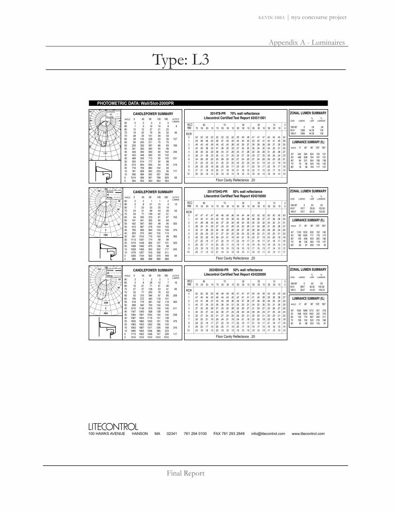
Final Report
Appendix A - Luminaires
kevin hsia | nyu concourse project
100 HAWKS AVENUE HANSON MA 02341 781 294 0100 FAX 781 293 2849 [email protected] www.litecontrol.com
90˚
150˚180˚
0˚
60˚
30˚
Across45Along
1200
1800
90 0 0 0 0 085 1 3 12 10 8 980 10 12 37 21 2075 19 22 79 35 32 4670 28 34 151 49 4365 38 133 228 63 56 10760 90 245 311 75 7055 233 332 397 86 83 18950 341 363 482 90 9645 433 393 563 90 102 23040 453 448 640 93 10235 469 526 713 92 100 23130 525 614 777 92 9825 613 694 835 94 95 21920 716 759 884 102 9315 781 858 920 223 95 17710 906 989 942 457 2465 1014 996 951 769 625 830 954 954 954 954 954
PHOTOMETRIC DATA: Wall/Slot-2000PR
RCR
2014T8-PR 70% wall reflectanceLitecontrol Certified Test Report #24311001
CANDLEPOWER SUMMARY
Floor Cavity Reflectance .20
ANGLE 0 45 90 135 180 OUTPUTLUMENS
RCC 80 70 50 30 10 0RW 70 50 30 10 70 50 30 10 50 30 10 50 30 10 50 30 10 0
0 .53 .53 .53 .53 .52 .52 .52 .52 .49 .49 .49 .47 .47 .47 .45 .45 .45 .441 .49 .48 .46 .45 .48 .47 .45 .44 .45 .44 .43 .43 .42 .41 .42 .41 .40 .392 .46 .43 .40 .38 .45 .42 .40 .38 .40 .39 .37 .39 .38 .36 .38 .37 .35 .353 .42 .39 .36 .33 .41 .38 .35 .33 .37 .34 .32 .36 .34 .32 .34 .33 .31 .304 .39 .35 .32 .29 .38 .34 .31 .29 .33 .31 .28 .32 .30 .28 .31 .29 .28 .275 .36 .31 .28 .25 .35 .31 .27 .25 .30 .27 .25 .29 .27 .25 .28 .26 .24 .236 .34 .28 .25 .22 .33 .28 .25 .22 .27 .24 .22 .27 .24 .22 .26 .23 .22 .217 .31 .26 .22 .20 .31 .25 .22 .20 .25 .22 .20 .24 .21 .19 .24 .21 .19 .198 .29 .23 .20 .18 .28 .23 .20 .17 .23 .20 .17 .22 .19 .17 .22 .19 .17 .169 .27 .21 .18 .16 .26 .21 .18 .16 .21 .18 .15 .20 .17 .15 .20 .17 .15 .14
10 .25 .20 .16 .14 .25 .19 .16 .14 .19 .16 .14 .18 .16 .14 .18 .16 .14 .13
% % ZONE LUMENS LAMP LUMINAIRE
180-90° 0 .00 .0090-0° 1286 44.35 100180-0° 1286 44.35 100
ZONAL LUMEN SUMMARY
ANGLE 0° 45° 90° 135° 180°
45° 644 584 834 134 15155° 428 608 724 157 15165° 94 331 564 158 13875° 76 90 320 140 13085° 16 38 149 117 101
LUMINANCE SUMMARY (fL)
90 0 0 1 1 285 5 8 21 10 4 1380 7 20 53 25 1975 24 31 89 44 26 6370 33 77 149 62 5165 44 265 223 81 67 16360 191 441 305 90 8455 432 597 393 98 95 30050 613 687 476 104 10345 760 809 564 103 109 37540 829 973 642 100 11335 941 1154 710 103 99 39030 1113 1337 774 99 9925 1319 1448 826 107 101 35320 1498 1492 875 136 9815 1558 1465 900 202 117 24010 1478 1357 916 348 2115 1259 1164 922 579 449 840 888 888 888 888 888
RCR
2014T5HO-PR 50% wall reflectanceLitecontrol Certified Test Report #24316000
CANDLEPOWER SUMMARY
Floor Cavity Reflectance .20
ANGLE 0 45 90 135 180 OUTPUTLUMENS
RCC 80 70 50 30 10 0RW 70 50 30 10 70 50 30 10 50 30 10 50 30 10 50 30 10 0
0 .47 .47 .47 .47 .46 .46 .46 .46 .44 .44 .44 .42 .42 .42 .40 .40 .40 .401 .44 .42 .41 .40 .43 .42 .40 .39 .40 .39 .38 .38 .38 .37 .37 .36 .36 .352 .41 .38 .36 .34 .40 .37 .35 .34 .36 .34 .33 .35 .33 .32 .34 .32 .31 .313 .38 .34 .31 .29 .37 .34 .31 .29 .33 .30 .29 .31 .30 .28 .31 .29 .28 .274 .35 .31 .28 .25 .34 .30 .28 .25 .29 .27 .25 .28 .26 .25 .28 .26 .24 .245 .32 .28 .24 .22 .31 .27 .24 .22 .26 .24 .22 .26 .23 .21 .25 .23 .21 .206 .30 .25 .22 .19 .29 .24 .21 .19 .24 .21 .19 .23 .21 .19 .23 .20 .19 .187 .27 .22 .19 .17 .27 .22 .19 .17 .22 .19 .17 .21 .19 .17 .21 .18 .17 .168 .25 .20 .17 .15 .25 .20 .17 .15 .19 .17 .15 .19 .16 .15 .19 .16 .15 .149 .23 .18 .15 .13 .23 .18 .15 .13 .18 .15 .13 .17 .15 .13 .17 .14 .13 .12
10 .22 .17 .14 .12 .21 .16 .14 .12 .16 .13 .11 .16 .13 .11 .15 .13 .11 .11
% % ZONE LUMENS LAMP LUMINAIRE
180-90° 0 .00 .0090-0° 1977 39.55 100.00180-0° 1977 39.55 100.00
ZONAL LUMEN SUMMARY
ANGLE 0° 45° 90° 135° 180°
45° 1130 1203 835 152 16355° 792 1094 717 179 17465° 109 658 553 200 16675° 96 126 360 179 107 85° 63 97 249 119 43
LUMINANCE SUMMARY (fL)
90˚
150˚180˚
0˚
60˚
30˚
Across45Along
2000
3000
90 3 1 2 3 185 3 8 28 12 7 1680 15 21 71 31 2675 27 37 128 53 41 8070 30 77 250 79 6365 52 310 346 97 85 20660 196 572 460 118 10155 518 775 581 132 119 39350 808 940 700 140 13345 1010 1136 819 135 146 51140 1187 1343 928 138 14035 1384 1591 1030 140 140 53830 1587 1804 1118 151 13825 1835 1882 1200 161 135 47520 1963 1903 1262 186 14515 1953 1897 1311 226 169 31610 1895 1805 1336 385 2235 1713 1652 1348 747 539 1170 1310 1310 1310 1310 1310
RCR
2024BX40-PR 50% wall reflectanceLitecontrol Certified Test Report #24320000
CANDLEPOWER SUMMARY
Floor Cavity Reflectance .20
ANGLE 0 45 90 135 180 OUTPUTLUMENS
RCC 80 70 50 30 10 0RW 70 50 30 10 70 50 30 10 50 30 10 50 30 10 50 30 10 0
0 .50 .50 .50 .50 .49 .49 .49 .49 .47 .47 .47 .45 .45 .45 .43 .43 .43 .421 .47 .45 .44 .43 .46 .44 .43 .42 .42 .41 .41 .41 .40 .39 .39 .39 .38 .372 .43 .41 .39 .37 .43 .40 .38 .36 .39 .37 .35 .37 .36 .35 .36 .35 .34 .333 .40 .37 .34 .32 .39 .36 .34 .31 .35 .33 .31 .34 .32 .30 .33 .31 .30 .294 .37 .33 .30 .28 .37 .33 .30 .28 .32 .29 .27 .31 .29 .27 .30 .28 .27 .265 .35 .30 .27 .24 .34 .30 .27 .24 .29 .26 .24 .28 .26 .24 .27 .25 .24 .236 .32 .27 .24 .22 .31 .27 .24 .22 .26 .23 .21 .25 .23 .21 .25 .23 .21 .207 .30 .25 .21 .19 .29 .24 .21 .19 .24 .21 .19 .23 .20 .19 .23 .20 .18 .188 .28 .22 .19 .17 .27 .22 .19 .17 .22 .19 .17 .21 .19 .17 .21 .18 .17 .169 .26 .20 .17 .15 .25 .20 .17 .15 .20 .17 .15 .19 .17 .15 .19 .16 .15 .14
10 .24 .19 .16 .13 .23 .18 .16 .13 .18 .15 .13 .18 .15 .13 .17 .15 .13 .13
% % ZONE LUMENS LAMP LUMINAIRE
180-90° 0 .00 .0090-0 2647 42.02 100.00180-0 2647 42.02 100.00
ZONAL LUMEN SUMMARY
ANGLE 0° 45° 90° 135° 180°
45° 1502 1689 1212 201 218 55 948 1420 1062 242 21865 130 770 857 242 211 75 108 150 520 216 166 85 34 98 333 142 81
LUMINANCE SUMMARY (fL)
Type: L3
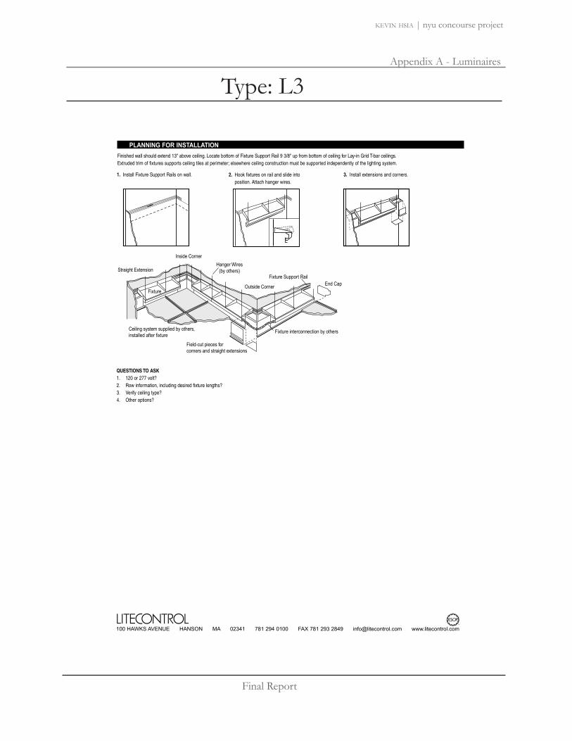
Final Report
Appendix A - Luminaires
kevin hsia | nyu concourse project
100 HAWKS AVENUE HANSON MA 02341 781 294 0100 FAX 781 293 2849 [email protected] www.litecontrol.com
PLANNING FOR INSTALLATIONFinished wall should extend 13" above ceiling. Locate bottom of Fixture Support Rail 9 3/8" up from bottom of ceiling for Lay-in Grid T-bar ceilings.Extruded trim of fixtures supports ceiling tiles at perimeter; elsewhere ceiling construction must be supported independently of the lighting system.
QUESTIONS TO ASK1. 120 or 277 volt?2. Row information, including desired fixture lengths?3. Verify ceiling type?4. Other options?
2. Hook fixtures on rail and slide into position. Attach hanger wires.
1. Install Fixture Support Rails on wall. 3. Install extensions and corners.
Straight Extension
Inside Corner
Ceiling system supplied by others,installed after fixture
Field-cut pieces forcorners and straight extensions
Fixture interconnection by others
FixtureEnd Cap
Fixture Support Rail
Outside Corner
Hanger Wires(by others)
Type: L3

Final Report
Appendix A - Luminaires
kevin hsia | nyu concourse project
Fixture Series Lamp Type LinearFootage
Finish Options
M6R1M60 RecessedContinuous Flange(Flanged Extrusion/Flanged Endcaps)
M6R2M60 RecessedFlush End(Flanged Extrusion/ Flangeless Endcaps)
004 4 foot
008 8 foot
012 12 foot
For actual lengths
see layout dimensions. For
other lengths, configurations
indicate nominal length
rounded to the next highest
foot. Factory will supply lay-
out drawings. Individual fix-
tures cannot be field joined.
120
277
347
WH White
BK Black
SV Silver
SP SpecifyRAL#
1T5 F28T5
1T5HO F54T5HO
Shielding Mounting
MA Matte Parabolic
MP Silky Specular ParabolicLouver
SD Satine Lens
OD Extra DiffuseLens
M60 Linear FluorescentRecessed
TB Lengths to Fit 2’ GridT-Bar Ceiling System (M6R1 only)
(qty.)EM Stand-by Battery Pack1
(prefix quantity, i.e. - 5EM)FS Single FusingDM Dimming1 (specify system)DMA Digital Addressable Dimming1
SI Satine Acrylic Inlay2
FW Flex Whip (standard)FW1 Flex Whip (dimming)Track Eutrac Standard3
DL Suitable for Damp LocationsCCEA Chicago PlenumDownlights (See MR11 spec
sheet, pp.98)1Must be low profile ballasts (13/8" wide x 13/16" high); consult factory for details. 2Available for MP Louver only. 3Consult factory for details.
Options (refer to separate data sheets for ordering codes and details)
_ _ _ _ _ _ _ _
Voltage
LampType
Shielding Mounting LinearFootage
FixtureSeries
_ _ _ _ _ _ _
Finish Voltage
Project: Type: Qty:
SH Suspension Clips
RC Rotating Crossbars
PM Perimeter Mount
TS 1" Studs (factory installed)
SELUX Corp. © 2006TEL: (845) 691-7723FAX: (845) 691-6749
www.selux.com/usaM6R-01 (v5.0)
M6R1M6R2
1. Housing - Continuous, 6063-T5 extruded aluminumprofile up to 16 feet long.
2. Ballast - Electronic, highpower factor, class "P", type "A"sound rating. Specify 120v,277v, or 347v. Ballast is factorypre-wired with leads to one endof fixture. Consult factory for ballast options.
3. Gear Tray - Die formed traywith specular aluminum reflec-tor. Gear tray installs as com-plete electrical unit and is heldin place with 1/4 turn latches. Itis fully accessible from belowceiling.
4. Flange - 5/16" (8mm) wideflange is part of the main extrud-ed body. Specify continuous flange (M6R1) orflush end (M6R2) .
5. Lamps - As noted (by others).Other lamp lengths or wattagesavailable, consult factory.
6. Shielding - Louvers offerexcellent glare control in longitudi-nal, lateral, and all diagonalplanes. High quality aluminumlouvers and acrylic shielding allowtrue freedom of layout for today’smodern spaces.
7. Spring steel suspension clips- Supplied two places, locatednominally every 4 ft. Supportwires Supplied and installed byothers.
8. Pre-installed 1" 1/4-20 Stud -Attached to fixture every nominal4 feet.
9. Coupling and Threaded Rodto Structure - Supplied andinstalled by others.
10 Rotating Crossbar - For inac-cessible ceilings, adjustable forceiling thicknesses from 1/4" to 2".Support required nominally every 4’.
11. Steel Wall Bracket and 1/4-20 Rod - Supplied nominallyevery 4 ft. (Fasteners to wall andwall anchors by others.)
12. Aluminum Wall Bracket -Secured to wall (fasteners andwall anchors by others) andruns entire length of fixture.Also supplied for width ofM6R1 continuous flange fixtures.Allows for 1/8" gap betweenflange and wall to create shadow line.
Interior Luminaire Finish -Standard interior colors are White (WH), Black (BK) andSilver (SV). RAL Classic colors(SP) are available, please specifyRAL#.
Mounting Diagrams
In a continuing effort to offer the best product possible, we reserve the right to change, without notice, specifications or materials that in our opinion will not alterthe function of the product. Specification sheets found at www.selux.com/usa are the most recent versions and supercede all other printed or electronic versions.
Union Made Affiliated
with IBEW Local 363
22
Scale
= 1
: 4
6
5
1
2
4
3
117 9 108
12
Suspension Clips (SH) Rotating Crossbars (RC)Pre-installed Rod (TS) Perimeter Mount (PM)
39 /16
"(9
0mm
)
39 /16
"(9
0mm
)
39 /16
"(9
0mm
)
41 /2"
(114
mm
)
39 /
16" (
90m
m)
3"(76mm)
23/8"(60mm)
Scale = 1 : 8 TrackTrack insert including trackavailable for all configurations,consult factory for details.
Type: L4

Final Report
Appendix A - Luminaires
kevin hsia | nyu concourse project
M60 Recessed Linear FluorescentFlanged Extrusion
M6R1 and M6R2 Standard Layout Dimensions
For other lengths, lamping, continuous runs or configurations please specify overall length (in feet), accessories desired and sketch/drawing ofconfiguration. SELUX will detail project drawings upon order and supply submittal drawings for approval. Individual fixtures cannot be fieldjoined. If you have any questions please contact SELUX customer service or applications engineering for assistance (1-800-SELUX-CS).
M6R1 Recessed - nominal 12 foot individual
M6R1 Recessed - T-Bar Length - nominal 12 foot individual
M6R1 Recessed - nominal 8 foot individual
M6R1 Recessed - T-Bar Length - nominal 8 foot individual
M6R1 Recessed - nominal 4 foot individual
M6R1 Recessed - T-Bar Length - nominal 4 foot individual
Typical Side View Including Endplates
Outside Flange (M6R1)
Outside Flange (M6R1)
Outside Flange (M6R1)
Outside Flange 3" (76mm)
23/8" (60mm)
23
equal equal equal
In a continuing effort to offer the best productpossible, we reserve the right to change, withoutnotice, specifications or materials that in ouropinion will not alter the function of the product.Specification sheets found at www.selux.com/usaare the most recent versions and supercede allother printed or electronic versions.
SELUX Corp. © 2006PO Box 1060, 5 Lumen Lane / Highland, NY 12528TEL: (845) 691-7723 / FAX: (845) 691-6749E-mail: [email protected] / Web Site: www.selux.com/usaM6R1-02 (02/06)
12’ CL to CL of T-Bar
2’ typical
8’ CL to CL of T-Bar
2’ typical
4’ CL to CL of T-Bar
2’ typical
Suspensions supplied spaced nominally every 4 feet. Fixture supplied with 7/8 knockout located 21/8" from end in top of fixture.
Housing 39/16" (90mm)
Flush End (M6R2)
Continuous Flange (M6R1)
21/8" (54mm) Feed
61/8"(156mm)
61/8" (156mm)
T5 (1 or 2 lamp)
47.91" (1216mm)
95.91" (2436mm)
143.91" (3655mm)
Outside FlangeM6R1 - TB
47.22" (1199mm)
95.22" (2419mm)
143.22" (3638mm)
Including EndplatesM6R1/M6R2 - TB
47.28" (1201mm)
93.72" (2380mm)
140.13" (3559mm)
Outside Flange
46.63" (1184mm)
93.03" (2363mm)
139.44" (3542mm)
4 foot individual8 foot individual
12 foot individual
Including EndplatesM6R1/M6R2 M6R1
17/8" (48mm) Blank Cover 17/8" (48mm)Blank Cover
13/32" (28mm) Blank Cover 13/32" (28mm)Blank Cover
Type: L4
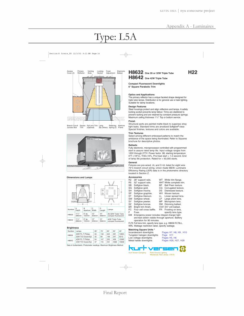
Final Report
Appendix A - Luminaires
kevin hsia | nyu concourse project
Kurt Versen Company Point Source LightingWestwood, New Jersey 07675
H22VentingSlots
Branch CircuitJunction Box
ApertureFrame
RetainingSpring (2)
Full Lens Trim(Optional)
SquareTrim
AccessCover (2)
LockingSocket
Lamp(By Others)
FocalAdjustment
ElectronicBallast
PrimaryReflector
ADepth
H8632 6 " sq.153mm
12 "305mm
14 "356mm
26-32W Triple Tubecompact fluorescent
LampsNumber BAperture
CWidth
DLength
111/4"286mm
H8642 6 " sq.153mm
12 "305mm
14 "356mm
42W Triple Tubecompact fluorescent
111/4"286mm
Dimensions and Lamps
B
A
C
D
Number Lamps 85° 75° 65° 55° 45°
H863232W PL-T Philips 55 132 224 391 10904
32W T/E Osram/Syl 32 84 148 247 9212
H864242W PL-T Philips 54 147 252 436 15069
42W T/E Osram/Syl 37 116 231 2369 15908
Data in footlamberts. Photometer readings, Maximum Brightness Method.
Brightness
H8632 One 26 or 32W Triple Tube
H8642 One 42W Triple Tube
Compact Fluorescent Downlights6" Square Parabolic Trim
Optics and ApplicationsThe primary reflector has a unique faceted shape designed fortriple tube lamps. Distribution is for general use or task lighting.Suitable for damp locations.
Design FeaturesSteel housings protect and align reflectors and lamps. A safetylocking socket prevents lamp fallout. Trims are stabilized toprevent racking and are retained by constant pressure springs.Maximum ceiling thickness 11/2". Top or bottom service.
FinishStructural parts are painted matte black to suppress straylight leaks. Standard trims are anodized Softglow® clear.Special finishes, textures and colors are available.
Trim TexturesSelect among different embossed patterns to match theambiance of the space being illuminated. Refer to Squaresbrochure for descriptive photos.
BallastsFully electronic, microprocessor controlled with programmedstart to assure rated lamp life. Input voltage ranges from120V through 277V. Power factor .98, starting temperature0°F (-18°C), THD<10%. Pre-heat start < 1.0 second. Endof lamp life protection. Rated for > 50,000 starts.
GeneralFixtures are pre-wired, UL and C-UL listed for eight wire75°C branch circuit wiring. Union made IBEW. LuminaireEfficiency Rating (LER) data is in the photometric directorylocated in Section Z.
AccessoriesR2 26" support rails. WT White trim flange.R5 52" support rails. WHT White complete trim.SB Softglow black. BP Ball Peen texture.SG Softglow gold. CG Corrugated texture.SH Softglow mocha. DS Distressed texture.SP Softglow graphite. WV Woven texture.ST Softglow titanium. LL Linear spread lens.SW Softglow wheat. LP Large prism lens.SY Softglow pewter. MP Microprism lens.SZ Softglow bronze. DM Dimming ballast.BR Bright trim finish. V347 347 volt ballast.FC Four cell cross baffle. FR Frosting on lens,F Fuse. specify lens type.EM Emergency power includes integral charger light
and test switch visible through aperture. Battery operation for 90 minutes.
FLT6 Full lens trim, specify lens type, e.g. H8632-FLT6LL.WRL Wattage restriction label, specify wattage.
Matching Square Units *Incandescent downlights Pages H7, H8, H9 , H10Tungsten halogen downlights Page H11Low voltage downlights Pages H5, H6Metal halide downlights Pages H26, H27, H28
Section H fronts_UG 12/3/02 9:21 AM Page 14
Type: L5A

Final Report
Appendix A - Luminaires
kevin hsia | nyu concourse project
H8632 One 32W Osram Read Bottom Data
10° 20° 30°
21
15
11
9
7
21
15
11
9
7
2'
2'
3'
3'
3'
17
12
9
7
6
4'
5'
5'
6'
7'
9
7
5
4
3
6'
8'
9'
10'
11'
6'
7'
8'
9'
10'
28
20
15
12
9
24
17
13
10
8
16
11
9
7
5
H8632 One 32W Philips Read Top Data
20
15
11
9
7
21
15
12
9
7
2'
2'
3'
3'
3'
18
13
10
8
6
4'
5'
5'
6'
7'
11
8
6
5
4
6'
8'
9'
10'
11'
7'
8'
9'
10'
11'
24
17
13
10
8
20
14
11
8
7
14
10
8
6
5
H22 H8632 H8642Performance Datachart
Coefficients of UtilizationCandelasCeiling
Wall % 70 50 30 10 10 50 10 10 0
80% 70% 50% 30% 0
Zonal Cavity Method - Floor Reflectance 20%RCR
50
1
2
3
4
5
6
7
8
9
10
50
05
1015202530354045505560657075808590
05
1015202530354045505560657075808590
° Vertical Angles* Initial Lamp Lumens
H8632 Osram 32W Triple Tube x .93H8642 Philips and Osram 42W Triple Tube x .86
P 42W
770814849850813724588436310176381713000000
3200*O 42W
898908903853797682550408297195861712000000
3200*°
°
° Vertical* Initial Lamp Lumens
P 32W
620643678692673615517389283174411511000000
2400*O 32W
6296506636486025294343392521668125141000000
2400*
Ceiling to FloorSingle Unit, Initial Footcandles, 30" Work Plane Multiple Units, Initial Footcandles, 30" Work Plane
Ceiling 80% Walls 50% Floor 20%
FC FC Diam Spacing RCR 1 RCR 3 RCR 8
Nadir
FC Diam FC Diam
Spacing is Maximum Over Work Plane
Notes1 For microprism spread lens multiply data x.88.
2 All data with standard trim, Softglow® clear.
3 Datachart degree headings measure one side from nadir. Diameter data includes both sides. Therefore the 20° column value describes a 40° pattern diameter at the work plane 30" above the floor. Footcandle values are at the diameter edge.
4 Datachart spacing is rounded off to the nearest foot.
5 Data by IES methods. Compact fluorescent data vary due to lamp lumen differences, power input, burning position, ambient temperature and ballast characteristics. A modification factor should be applied.
6 Colored trim multipliers: Gold x .90, Wheat x .85, Mocha x .80, Pewter x .80, Graphite x .75, Titanium x .75, Bronze x .70, Black x .70.
H8642 One 42W Osram Read Bottom Data
10° 20° 30°
30
21
16
12
10
29
20
15
12
16
2'
2'
3'
3'
3'
22
16
12
9
7
4'
5'
5'
6'
7'
12
8
6
5
4
6'
8'
9'
10'
11'
8'
9'
10'
11'
12'
8'
9'
10'
11'
12'
6'
7'
8'
9'
10'
38
27
21
16
13
32
23
17
13
11
23
16
12
10
8
H8642 One 42W Philips Read Top Data
25
18
14
11
9
27
19
14
11
9
2'
2'
3'
3'
3'
22
16
12
9
7
4'
5'
5'
6'
7'
13
9
7
5
4
6'
8'
9'
10'
11'
6'
7'
9'
10'
11'
30
22
16
13
10
26
19
14
11
9
18
13
10
7
6
Ceiling to FloorSingle Unit, Initial Footcandles, 30" Work Plane Multiple Units, Initial Footcandles, 30" Work Plane
Ceiling 80% Walls 50% Floor 20%
FC FC Diam Spacing RCR 1 RCR 3 RCR 8
Nadir
FC Diam FC Diam
Spacing is Maximum Over Work Plane
H8632 32W PhilipsEff 39% S/M 1.19
H8632 32W OsramEff. 36% S/M 1.07
65
130
195
260
325
390
455
520
585
650
65
130
195
260
325
390
455
520
585
650
Candlepower Distribution
For 26 Watt x.88
H8642 42W PhilipsEff 34% S/M 1.14
H8642 42W OsramEff. 34% S/M 1.01
85
170
255
340
425
510
595
680
765
850
90
180
270
360
450
540
630
720
810
900
55°
35°
75°
65°
25°
15°5°
45°
85°
55°
35°
75°
65°
25°
15°5°
45°
85°
55°
35°
75°
65°
25°
15°°
45°
85°
55°
35°
75°
65°
25°
15°5°
45°
85°
.44
.42
.39
.37
.35
.33
.31
.29
.28
.26
.43
.40
.36
.34
.31
.29
.27
.25
.23
.22
.42
.38
.34
.31
.29
.26
.24
.22
.21
.19
.41
.36
.33
.30
.27
.25
.23
.21
.19
.18
.42
.39
.36
.33
.31
.29
.27
.25
.23
.22
.40
.36
.32
.29
.27
.24
.22
.21
.19
.18
.40
.38
.35
.32
.30
.28
.26
.24
.23
.21
.39
.35
.32
.29
.26
.24
.22
.21
.19
.18
.39
.36
.34
.32
.29
.27
.26
.24
.22
.21
.38
.34
.31
.29
.26
.24
.22
.20
.19
.18
.36
.33
.30
.28
.25
.23
.21
.20
.18
.17
Section H backs_UG 12/3/02 1:43 AM Page 14
Type: L5A

Final Report
Appendix A - Luminaires
kevin hsia | nyu concourse project
VentilationSlots
HousingTop
BallastLamp(By Others)
Branch CircuitJunction Box
MicroprismLens
SafetyChain
ApertureFrame Housing
SquareTrimReflector
H8653 6" sq.153mm
131/2"343mm
19 "483mm
LampsNumber ADepth
BAperture
CWidth
DLength
51/2"140mm
Dimensions and Lamps
B
A
C
D
26-32-42WTriple Tubecompact fluorescent
H37
Kurt Versen Company Point Source LightingWestwood, New Jersey 07675
H8653Wall WasherOne 26-32-42W Triple Tube Compact Fluorescent Lamp6" Parabolic Trim
Optics and ApplicationsPrimary and kicker reflectors work with a microprism spreadlens to produce wide lateral spread, light close to the ceilingand a uniformly illuminated wall. The pattern is devoid ofhot spots or striations. Suitable for damp locations. Use towash walls or accentuate objects of special interest.
Design FeaturesThe faceted compound curve reflector is designed for tripletube lamps. The trim is stabilized to prevent racking and is held to the ceiling by constant pressure springs. Afterinstallation, the trim and optical assembly may be rotated360° in 90° increments if orientation to the wall is incorrect.Maximum ceiling thickness 7/8". Top or bottom service.
FinishHousing and structural parts are painted matte black to suppress stray light leaks. Standard trim is anodizedSoftglow® clear. Special finishes, textures and colorsavailable, see below under Accessories.
Trim TexturesTextured trims create a subtle new aperture appearance.Select among different embossed patterns to match theambiance of the space being illuminated. Refer to Squaresbrochure for descriptive photos.
BallastFully electronic, microprocessor controlled with programmedstart to assure rated lamp life. Input voltage ranges from120V through 277V. Operates 26W, 32W or 42W triple tubelamps interchangeably. Power factor .98, starting temper-ature 0°F (-18°C), THD<10%. Pre-heat start < 1.0 secondEnd of lamp life protection. Rated for > 50,000 starts.
GeneralFixtures are pre-wired, UL and C-UL listed for eight wire75°C branch circuit wiring. Union made IBEW. LuminaireEfficiency Ratings (LER) do not apply to wall washers.
AccessoriesR2 26" support rails. WT White trim flange.R5 52" support rails. WHT White complete trim.SB Softglow black. BP Ball Peen texture.SG Softglow gold. CG Corrugated texture.SH Softglow mocha. DS Distressed texture.SP Softglow graphite. WV Woven texture.ST Softglow titanium. BR Bright trim finish.SW Softglow wheat. LL Linear spread lens.SY Softglow pewter. LP Large prism lens.SZ Softglow bronze. FR Frosting on lens.F Fuse. V347 347 volt ballast.DM Dimming ballast. Specify watts and volts.EM Emergency power includes integral charger light
and test switch visible through aperture. Battery operation for 90 minutes.
WRL Wattage restriction label, specify wattage.See Squares brochure for more accessories data.
Matching Square Units *Directional downlights Pages H5, H6, H9, H24, H27Straight downlights Pages H7, H8, H10, H11,
H22, H23, H26, H28
Section H fronts_UG 12/3/02 9:22 AM Page 27
Type: L5B

Final Report
Appendix A - Luminaires
kevin hsia | nyu concourse project
H37 H8653Candlepower Distribution Curves Multiple Units Footcandles
H8653 32W PL-T Philips H8653 32W PL-T Philips
H8653 42W PL-T Philips H8653 42W PL-T Philips
Notes
2' from wall
C/L
2' Centers
2
4
6
6
6
5
4
4
3
3
5
9
9
8
7
6
5
4
3
3
4
9
11
11
9
8
7
5
4
4
5
10
12
11
9
8
7
6
5
4
5
12
13
11
9
7
6
5
4
3
12
17
15
12
10
7
6
5
4
3
10
19
19
16
12
10
8
6
5
4
13
20
19
16
13
10
8
6
5
4
19
26
20
14
10
7
5
4
3
3
35
32
22
15
10
7
6
4
3
3
33
41
31
21
15
11
8
6
5
4
40
42
31
22
15
11
8
6
5
4
1'
2'
3'
4'
5'
6'
7'
8'
9'
10'
3' Centers
3' from wall
3' Centers 4' Centers
4' from wall
4' Centers 6' Centers
Mid C/L Mid C/L Mid C/L Mid C/L Mid C/L Mid
FromCeiling
2' from wall
C/L
2' Centers
2
6
8
8
8
7
6
5
4
3
6
11
12
10
8
7
6
5
4
3
5
12
14
14
12
10
8
7
6
5
7
13
15
14
12
10
8
7
6
5
8
16
17
15
12
9
7
6
5
4
15
22
19
15
12
9
7
6
5
4
14
25
24
20
16
12
10
8
6
5
16
26
25
20
16
13
10
8
6
5
27
34
26
18
13
9
7
5
4
3
44
40
27
18
13
9
7
5
4
3
46
54
40
27
19
14
10
8
6
5
52
54
39
27
19
14
10
8
6
5
3' Centers
3' from wall
3' Centers 4' Centers
4' from wall
4' Centers 6' Centers
Mid C/L Mid C/L Mid C/L Mid C/L Mid C/L Mid
1'
2'
3'
4'
5'
6'
7'
8'
9'
10'
FromCeiling
Kurt Versen Company, Westwood, New Jersey
Number
42W PL-T Philips
Lamps
H8653
32W PL-T Philips
85° 75° 65° 55° 45°
38 153 286 1471 2552
77 230 464 1988 3270
Brightness1 All data calculated with Softglow® clear trims and a microprism spread lens.
2 If colored trims are required, only the lens trim will be tinted. Primary and kicker reflectors are always clear Alzak for maximum output and true color rendition. Multipliers should be used to correct brightness and downlight data only. Multiple units footcandles are correct as reported above.
3 Colored trim multipliers: Gold x .90, Wheat x .85, Mocha x .80, Pewter x .80, Graphite x .75, Titanium x .75, Bronze x .70, Black x .70.
4 Above data measure output of the wall washers only. No contribution from adjacent downlights or ceiling, floor or wall reflectances is included. Total illumination on the wall will increase with the contribution from other sources.
5 Data are cosine corrected to the plane of the wall. Uncorrected data are much higher and depend upon the angle of incidence to the wall whichvaries with the mounting distance from the wall.
6 Kurt Versen wall washers minimize hard shadow lines at the ceiling.Intensity increases gradually to just above eye level. The illuminatedfield is uniform and devoid of hot spots, striations and spikes.
7 Brightness data from the Average Luminance Method are inaccurate for downlights. They are theoretical calculations for large surfaces such as troffer lenses. We recommend the stricter standard of Maximum Brightness Method point data from direct photometer readings. They approximate what the human eye perceives when evaluating glare. For more information refer to Z section brochure Z1.
42W T/E Osram
32W T/E Osram 54 134 284 1543 2453
50 180 356 1633 2690
Data in footlamberts. Photometer readings. Maximum Brightness Method. See note 7.
45
90
135
180
225
270
315
360
405
450
55
110
165
220
275
330
385
440
495
550
Wall Washer
Wall Washer
Downlight
Downlight
55°
35°
45°
75°
65°
85°
5°15° 5° 15°
55°
35°
45°
75°
65°
25°25°
85°
55°
35°
45°
75°
65°
85°
5°15°25° 5° 15°
55°
35°
45°
75°
65°
25°
85°
Section H backs_UG 12/3/02 1:51 AM Page 27
Type: L5B

Final Report
Appendix A - Luminaires
kevin hsia | nyu concourse project
Type: L6
CUSTOM LUMINAIRE

Final Report
Appendix A - Luminaires
kevin hsia | nyu concourse project
35°�
5"
3" Max.
PROJECT NAME :
TYPE :
MODEL :
SUBMITTAL APPROVED BY :
DATE :
Adjustable Linear Fluorescent - Patent Pending
AX T5 Performance Linear Cove System
PRODUCT | AX SERIES
HOW TO SPECIFY | Product Code
LUMINAIRE LENGTHS
LUMINAIRE DIMENSIONS
28 - 28 watt T5
21 - 21 watt T5
14 - 14 watt T5
AX - T5 S2 - 2 lamps (Tandem)
S1 - 1 lamp
92 - 28 watt / S2 / 92.5 in.
46 - 28 watt / S1 / 46.25 in.
69 - 21 watt / S2 / 69 in.
34 - 21 watt / S1 / 34.5 in.
22 - 14 watt / S1 / 22.75 in.
U - Universal120 through 277V
1 - 120V
2 - 277V
E -� Electronic HPF
D1 -�Digital Dimming � DALI compatible
D3 -�Lutron Eco-10™
S 1 S 228 Watt
S 1 S 221 Watt
S 114 Watt
28 Watt
21 Watt
46 1/4"
34 1/2"
22 3/4"
92 1/2"
69"
PRODUCT� LAMP� LAMP CONFIG.� VOLTAGE� BALLAST� LUMINAIRE LENGTH� OPTIONS
AX
Please SpecifyVoltage For Dimming
© ELECTRIX, INC. 45 SPRING STREET NEW HAVEN, CT 06519 � 203.776.5577 203.624.7545 [email protected] www.electrix.com
Recommended » Minimum Cove DimensionsFor Zero Degree Line Of Sight
� Distance From� Width� Cove� Ceiling To Cove� � Facade
� T5 HO-18"� T5-12"� 8"� 3"� T8-10"
EM - Emergency� � Ballast
4' nominal lamp only
AX
Set Field To Current Date
Reset Product Code Reset Entire Form
Type: L7
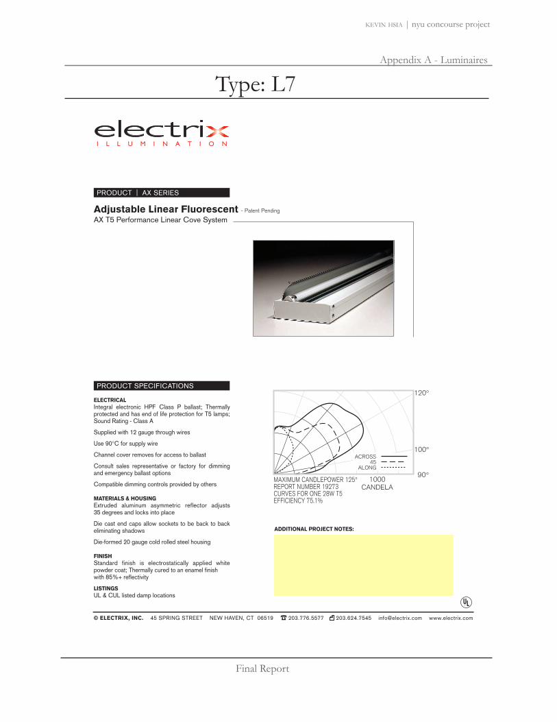
Final Report
Appendix A - Luminaires
kevin hsia | nyu concourse project
Adjustable Linear Fluorescent - Patent Pending
AX T5 Performance Linear Cove System
PRODUCT | AX SERIES
100°
120°
90°
ACROSS45
ALONG
1000CANDELA
MAXIMUM CANDLEPOWER 125°REPORT NUMBER 19273CURVES FOR ONE 28W T5EFFICIENCY 75.1%
© ELECTRIX, INC. 45 SPRING STREET NEW HAVEN, CT 06519 � 203.776.5577 203.624.7545 [email protected] www.electrix.com
PRODUCT SPECIFICATIONS
ELECTRICALIntegral electronic HPF Class P ballast; Thermally protected and has end of life protection for T5 lamps; Sound Rating - Class A
Supplied with 12 gauge through wires
Use 90°C for supply wire
Channel cover removes for access to ballast
Consult sales representative or factory for dimming and emergency ballast options
Compatible dimming controls provided by others
MATERIALS & HOUSINGExtruded aluminum asymmetric reflector adjusts 35 degrees and locks into place
Die cast end caps allow sockets to be back to back eliminating shadows
Die-formed 20 gauge cold rolled steel housing
FINISHStandard finish is electrostatically applied white powder coat; Thermally cured to an enamel finish with 85%+ reflectivity
LISTINGSUL & CUL listed damp locations
ADDITIONAL PROJECT NOTES:
Type: L7

Final Report
Appendix A - Luminaires
kevin hsia | nyu concourse project
2 x 2G11, 24 W26983. 06/2832
glass tube clear, glass tube satin1 x T10 halogen medium basemax. 150 W, 120 VAC16151. 06/2832
1 x GX24q-4, 42 W16991. 06/2830
glass tube clear, glass tube satin1 x T10 halogen medium basemax. 100 W, 120 VAC16149. 06/2830
PUBLICsatin nickel glass tube clearacrylic tube satinwith electronic ballast120 / 277 VAC
contact factory for dimming options
mounting note: canopy to �tstandard junction box
2 x 2G11, 18 W26982. 06/2831
glass tube clear, glass tube satin1 x T10 halogen medium basemax. 150 W, 120 VAC16150. 06/2831
GX24q-4 2G11
PUBLIC
see chapterwall lights
see chapterceiling lights
T10
inter- lux www.inter-lux.com
Type: L8

Final Report
Appendix A - Luminaires
kevin hsia | nyu concourse project
Type:BEGA Product:
Project:Voltage:
Color:Options:
Modified:
BEGA-US 1000 BEGA Way, Carpinteria, CA 93013 (805) 684-0533 FAX (805) 566-9474 www.bega-us .com ©copyright BEGA-US 2008 Updated 2/08
Recessed luminaires · unshielded
Lumen A B C
2287 P 1 13 W CF twin-2p 825 1113⁄16 2 9⁄16 4 1⁄4
Housing: Constructed of die-cast and extruded aluminum with integral wiring compartment. Mounting tabs provided.
Enclosure: One piece die-cast aluminum faceplate. 1⁄8" thick, clear tempered glass with translucent white ceramic coating. Faceplate is secured by two (2) socket head, stainless steel, captive screws threaded into stainless steel inserts in the housing casting. Continuous high temperature O-ring gasket for weather tight operation.
Electrical: (Fluorescent) Lampholder; type GX23 (13 W) rated 75 W, 250 V. Ballasts are magnetic, available 120Vor 277 V - specify. Through Wiring: All units are suitable for a maximum of four (4) No. 12 AWG conductors (plus ground) suitable for 75° C. Two 7/8" knockouts provided for 1⁄2" conduit.
Finish: Available in five standard BEGA colors: Black (BLK); White (WHT); Bronze (BRZ); Silver (SLV); Eurocoat™ (URO). To specify, add appropriate suffix to catalog number.Custom colors supplied on special order.
U.L. listed, suitable for wet locations and for installation within 3 feet of ground. Suitable for all types of construction including poured concrete. Protection class: IP 64.
Recessed wall luminaires · unshielded for wall and steps
A
B
C
Type: L9

Final Report
Appendix A - Luminaires
kevin hsia | nyu concourse project
Light OutputTwo luminous intensities are available for white light. IES format files may be obtained from the factory or downloaded from www.iolighting.com.
Standard Output: High Output: 3000K White: 34 lms/ft 3000K White: 170 lms/ft 5000K White: 40 lms/ft 5000K White: 230 lms/ft
Constructionluxrail may be post mounted or wall mounted. Mounting hardware (post or wall) is typically required up to 5' O.C., depending on the handrail alloy. Final post and wall bracket spacing must be determined by a licensed architect or structural engineer. luxrail is available in stainless steel and aluminum. The lighting fixture component of the luxrail is a stand alone unit and is available in incremental nominal lengths that range from 6" to 60". Vandal resistant access chamber allows units to be removed for maintenance purposes.
All handrail component parts are engineered for quick installation. Field welding or cutting is typically not required. All parts are prefabricated to field dimensions and are assembled in the field with mechanical connection or epoxy.
The light fixture’s housing is made of a light weight, yet durable aluminum, providing the recommended heat sink requirements for the LEDs. Housing, patented optical assembly and stainless steel end caps are bonded to prevent water infiltration.
Electricalluxrail houses a low voltage LED-based light fixture that is integrated into the underside of the handrail. It comes complete with the linear light fixture installed in the handrail. 24 volt 100 watt power supplies are provided as a standard. See daisy chain and remote distance requirements in chart on the lower left corner of this specification sheet.
Power supply and dimming module must be specified separately. For detailed information, see luxrail brochure or download the power supply specification sheet from www.iolighting.com.
Power Consumption Standard Output: 2.1 w/ft High Output: 7.6 w/ft
Power consumption does not include power supply losses. Consult io driver specification sheets (at www.iolighting.com) for losses associated with each driver option.
ApplicationANSI and ADA compliant, luxrail is an indoor/outdoor LED-based handrail that delivers functional illumination. Two intensities may be specified: standard output and high output. The standard light output version delivers illuminance levels appropriate for exterior applications (2 footcandles at grade) as well as for dark interior environments with low ambient illumination levels, (e.g., theatres, themed environments). The high output version delivers illuminance levels applicable to interior environments – providing in excess of 10 footcandles along the path of egress (ANSI required for stair treads). Independent photometric test reports and IES Format data are available at www.iolighting.com.
luxrail’s standard handrail gripping surfaces are circular in cross section and meet 2004 ADAAG (Americans with Disability Act Accessibility Guidelines). Patented optical assemblies deliver 10˚, 45˚ and 65˚ beam spreads. The 45˚ and 65˚ beam patterns are most suitable for illuminating pathways, while the 10˚ beam spread offers accent lighting to optional glass or stainless steel cable railing infills. Reference page 41 (luxrail brochure) for information regarding infill options. io ensures that each LED is driven with the proper current and voltage, which enables the average rated life to be 50,000 hours at 70% of lamp lumen output. Ambient temperature surrounding the fixture shall not exceed 120˚F (48.9˚C).
luxrailTM
Dim
ensi
ons
Pow
er S
uppl
yBe
am S
prea
ds
io Lighting 370 Corporate Woods Parkway Vernon Hills, IL 60061-3107 T 847.735.7000 F 847.735.7001 E [email protected] W iolighting.com
2007 - io Lighting reserves the right to change specifications for product improvement without notification
Type: L10

Final Report
Appendix A - Luminaires
kevin hsia | nyu concourse project
1. PRODUCT FAMILY06 luxrail
2. ALLOY / FINISHSSS Stainless Steel Satin SSP Stainless Steel PolishedCAA Clear Anodized Aluminum (7)
3. SIZE1 1.66" O.D. (11⁄4" pipe size) (7)
[available for SS & CAA] 2 1.90" O.D. (11⁄2" pipe size) [available for SS & CAA]
4. MOUNTINGPM Post Mounted (7)
WM Wall or Guard Rail Mounted
5. INFILLAC Aircraft Cable (5) GL Glass (provided by others)C CustomNR Not Required
6. LIGHT DISTRIBUTION10 10 Degree45 45 Degree65 65 DegreeNI Handrail only (not illuminated)
7. LIGHT COLOR3k Warm White (3)
5k Cool White (3)
3kHO Warm White (3)
5kHO Cool White (3)
R Red (4)
G Green (4)
B Blue (4)
8. LENGTH Provide overall length of each
handrail section. Reference Footnote #2(6)
9. VOLTAGE / DIMMING1 120v2 277v3 120v w/dim4 277v w/dim5 Other
10. SPECIFY DRIVER / DIMMING(1)
Note: If left blank, io will supply 100 watt drivers. Download Power Supply specification sheet from www.iolighting.com
0io 1 2 3 4 5 6 7 8
Lig
ht O
utpu
t / D
istr
ibut
ions
Mou
ntin
g /
Infil
l Opt
ions
Orde
r Co
de
9
PM (post mounted) Glass infill Stainless steel cable infill(glass provided by others)
BEAM SPREAD OPTIONS
WALL MOUNT DETAILS*
10
POST MOUNT APPLICATION
LIGHT OUTPUT - 65 DEGREE WARM WHITE
WM (wall mount intermediate)
06
* Wall mounted luxrail may be mounted to new or existing guardrail (by others).
Post and wall bracket spacing must be provided by a licensed architect or structural engineer.
Footnotes1. Power Supply Specification Sheet may be downloaded from www.iolighting.com.2. Each handrail application will be somewhat custom to accommodate varying field conditions and design
requirements. Shop drawings will be required to manage specifics of each handrail section.3. White light variance between LEDs within a single fixture will not exceed +/- 200K. 4. High Output only - 7.6w/ft.5. Aircraft cable available for flat surfaces only.6. Elevation drawings required.7. 1.66" OD, post mounted railings are not available in aluminum. Stainless steel only.
Foot
note
s
io Lighting 370 Corporate Woods Parkway Vernon Hills, IL 60061-3107 T 847.735.7000 F 847.735.7001 E [email protected] W iolighting.com
2007 - io Lighting reserves the right to change specifications for product improvement without notification
luxrail
Type: L10
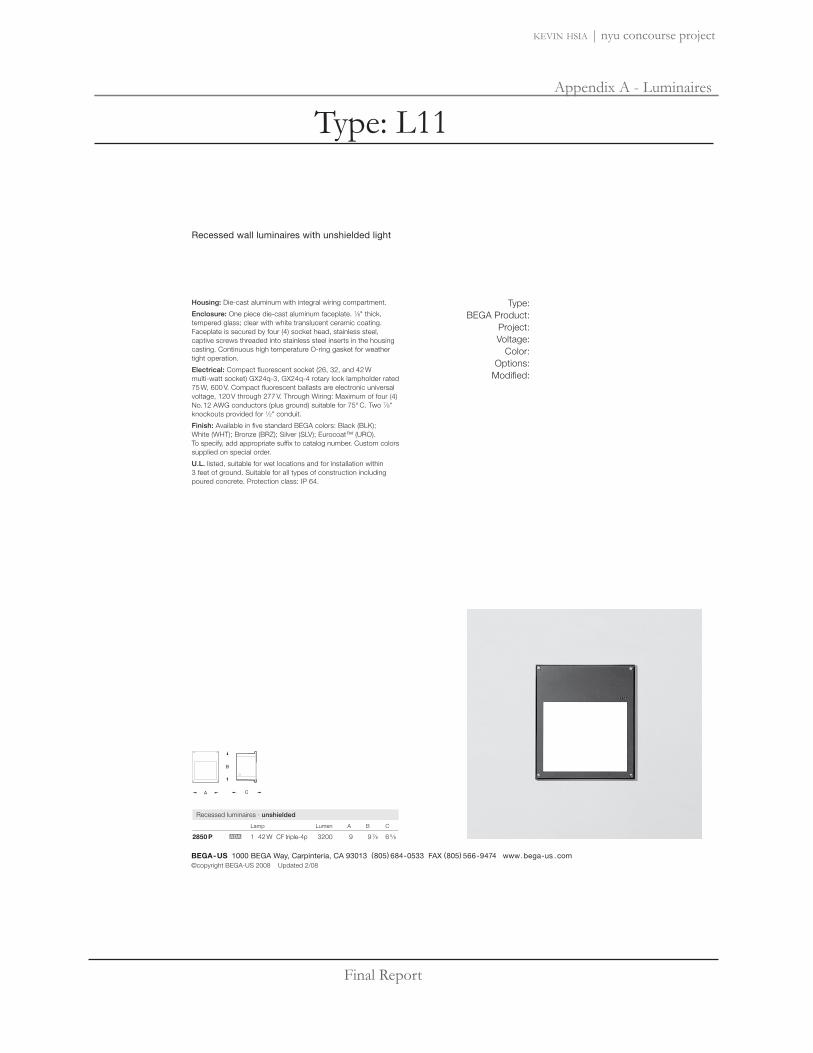
Final Report
Appendix A - Luminaires
kevin hsia | nyu concourse project
Recessed luminaires · unshielded
Lamp Lumen A B C
2850 P 1 42 W CF triple-4p 3200 9 9 7⁄8 6 5⁄8
Recessed wall luminaires with unshielded light
Type:BEGA Product:
Project:Voltage:
Color:Options:
Modified:
BEGA-US 1000 BEGA Way, Carpinteria, CA 93013 (805) 684-0533 FAX (805) 566-9474 www.bega-us .com ©copyright BEGA-US 2008 Updated 2/08
B
A C
Housing: Die-cast aluminum with integral wiring compartment.
Enclosure: One piece die-cast aluminum faceplate. 1⁄8" thick, tempered glass; clear with white translucent ceramic coating. Faceplate is secured by four (4) socket head, stainless steel, captive screws threaded into stainless steel inserts in the housing casting. Continuous high temperature O-ring gasket for weather tight operation.
Electrical: Compact fluorescent socket (26, 32, and 42 W multi-watt socket) GX24q-3, GX24q-4 rotary lock lampholder rated 75 W, 600 V. Compact fluorescent ballasts are electronic universal voltage, 120 V through 277 V. Through Wiring: Maximum of four (4) No. 12 AWG conductors (plus ground) suitable for 75° C. Two 7⁄8" knockouts provided for 1⁄2" conduit.
Finish: Available in five standard BEGA colors: Black (BLK); White (WHT); Bronze (BRZ); Silver (SLV); Eurocoat™ (URO). To specify, add appropriate suffix to catalog number. Custom colors supplied on special order.
U.L. listed, suitable for wet locations and for installation within 3 feet of ground. Suitable for all types of construction including poured concrete. Protection class: IP 64.
Type: L11

Final Report
Appendix A - Luminaires
kevin hsia | nyu concourse project
E Tesis In-ground luminaireLens wallwasher for metal halide lamps
2 1666
346666666
3 46666666666666
T4
Size 540°
N äDry
öDamp
üWet
ÖOutdoor
33715.023 Reflector silverT4 39W G8.5 3300lmECG
Product descriptionHousing: corrosion-resistant, castaluminum, No-rinse surface treat-ment. Black double powder-coated.Lampholder 360° rotation. Mount-ing by means of an adjustable bar.Clamp extension 3/16"-1 37/64"/ 5-40mm.Electronic control gear 120V/277V,60Hz. Cable, L 39" / 1m.Wallwasher reflector: aluminum,silver anodized.Low brightness reflector: alu-minum, silver, specular anodized,with wallwasher lens. Cut-off angle40° from horizontal. Without spilllight.Screw-fastened cover ring withflush safety glass: corrosion resis-tant stainless steel. Safety glass:1/2"/ 12mm, clear.Can be driven over by vehicles withpneumatic tyres. Load 10116lb.wt /45kN.Suitable for wet location (IP68):dust-proof.Weight 13.89lbs / 6.30kgTemperature on the cover glass150°F / 65°C
ERCO Lighting Inc.160 Raritan Center ParkwaySuite 10Edison, NJ 08837USATel.: +1 732 225 8856Fax: +1 732 225 [email protected]
Technical Region: 120V/277V, 60HzEdition: 12.02.2008Please download latest version fromwww.erco.com/33715.023
1/3
Type: L12

Final Report
Appendix A - Luminaires
kevin hsia | nyu concourse project
E Tesis In-ground luminairePlanning Data
Illuminance (fc)Specifications:Number of luminaires n > 5Light loss factor 0.80Without indirect componentWithout peripheral areaWall height (ft) 12T4 39W G8.5 3300lm
Offset from wall (ft) 4 4 5 5Luminaire spacing (ft) 4 5 5 6
Distance from ceiling (ft)below theluminaire
between theluminaires
below theluminaire
between theluminaires
below theluminaire
between theluminaires
below theluminaire
between theluminaires
12.000 8 7 7 6 8 7 7 611.000 10 8 8 7 10 9 8 710.000 12 10 10 9 11 10 9 99.000 15 13 12 11 12 11 10 108.000 17 15 14 13 13 12 11 107.000 19 18 16 15 13 12 12 106.000 21 19 17 15 13 11 11 95.000 20 18 18 14 10 9 9 74.000 16 14 14 10 6 6 6 43.000 9 8 8 6 3 3 3 22.000 3 3 3 2 1 1 1 11.000 0 0 0 0 0 0 0 00.000 0 0 0 0 0 0 0 0
Tesis In-ground luminaire 2/333715.023
Type: L12

Final Report
Appendix A - Luminaires
kevin hsia | nyu concourse project
E Tesis In-ground luminaireAccessories
33950.000Domed glassTo prevent accumulation of dirt.Load: 1125lb.wt / 5kN.Cannot be driven over by vehicles.
33962.000Housing for recessed mountingCorrosion-resistant cast aluminum,No-Rinse surface treatment. Blackdouble powder-coated. 2 cable en-tries.Weight 12.79lbs / 5.80kg
346666666
436666666
6666664 3666666
66666664 3666
21666666
Tesis In-ground luminaire 3/333715.023
Type: L12

Final Report
Appendix A - Luminaires
kevin hsia | nyu concourse project
223
4.9”/5.9”
4.1”
DesignLouis Poulsen Lighting A/S
ConceptNimbus Power LED with 9 light emitting diodes with a nominal load of 9W provides color, accent and marker illumination, and sets scenes, creating drama and highlighting architectural features.
FinishStainless steel.
MaterialSleeve: Marine grade 316 stainless steel. Glass: Tempered anti-slip glass or tempered clear glass. Top plate: Marine grade 316 stainless steel. Housing: Anodized and powder coated paint containing PTFE, die cast aluminum.
MountingSleeve: Recommended mounting in optional installation sleeve. Inground: Suitable for burial in earth/gravel or cast into concrete.
WeightMax. 7 lbs.
LabelcUL, Wet location. IBEW.
| Product code | Light source | Voltage | Finish | Diff./Encl./Glass | Top plate style | Options | | NIM-PWR | 9 LED Amber | 120V | ST STEEL | ANTI-SLIP | BEVELED | W/ SLEEVE || | 9 LED Blue | 277V | | CLEAR | STRAIGHT | W/O SLEEVE || | 9 LED White | | | | | || | | | | | | |
Weblink192
inground & onground
Nimbus Power LED
Info notes:I. Provided with integral pre-assembled LED board and 120V or 277V transformer.II. The comparable EU version has the following classifi cation: Ingress Protection Code: IP67.
220
222 221
Louis Poulsen Lighting exhibition 2006. Frankfurt, Germany. Architects: Julien de Smeet/JDS, Copenhagen, Denmark. Lighting Designer: Louis Poulsen Lighting IMD. Photo: Udo Kowalski
Project page268, 306, 352
Type: L13

Final Report
Appendix A - Luminaires
kevin hsia | nyu concourse project
Door pivots open from lampchamber for relamping. Threecaptive stainless steel screwssecure lamp cover in position.
4. Lamp - One coated, basedown, medium base ED-17 metalhalide or high pressure sodiumup to 150w; 70w or 150w ceram-ic G12 base T6 metal halide (830- 3,000º K); or 85w or 165w QLinduction lamp (840 - 4,000” K).Other lamps/colors available,consult factory. Lamp suppliedwith fixture unless otherwisespecified.
5. Optic Chamber - Die cast alu-minum optic chamber houseshighly specular precision reflector& 4KV pulse rated medium basesocket and lamp. Secures topole fitter with quarter turn mech-anism, locked in place with a sin-gle screw. Optic chamber is re-movable from pole fitter for bal-last access, without the necessityof re-moving the fixture headfrom the pole.
6. Ballast - A high-efficiency,pulse start, core and coil ballastfactory wired to socket. Remov-able ballast bracket is secured tooptic chamber for ease of main-tenance. Consult factory formore detailed ballast information.
7. Pole Fitter - Die cast aluminumfitter secures fixture arms andreflective shade to pole. Taperedto continue lines from pole.
8. Pole - Pole to be aluminumand taper from 5" diameter at thebottom to 7" diameter at the top.Pole wall thickness to be mini-mum 0.156 thick, supplied with a3" x 5" hand hole, with cast 356aluminum tempered to a T6 con-dition reinforced frame, with inte-gral ground lug connection andgasketed flush fitting door.
9. Base Cover - (not shown)Standard two-piece base cover ismade from die-cast 356 alloy alu-minum which is heat treated toproduce a T6 temper, measuring41/2" (115mm) height by 121/2"(316mm) diameter.
Exterior Luminaire Finish -SELUX utilizes a high qualityPolyester Powder Coating. All SELUX luminaires and polesundergo a five stage intensivepretreatment process whereproduct is thoroughly cleaned,phosphated and sealed. SELUXpowder coated products provideexcellent salt and humidity resistance as well as ultra violetresistance for color retention. All products are tested in accor-dance with test specifications forcoatings from ASTM and PCI.Standard exterior colors areWhite (WH), Black (BK), Bronze (BZ), and Silver (SV). RAL colors (SP) are available,please specify RAL#.
1
3
4
2
7
5
8
6
Ritorno® Round Symmetrical
26 13/16"(681 mm)
Ø 35 3/4(908mm)
Project:
Type: Qty:
Mounting Lamp Type / Wattage Finish Voltage Options
WH WhiteBK BlackBZ BronzeSV SilverSP Specify
RAL#
RRS Ritorno® RoundSymmetrical
RRS LZ6
Ritorno® RoundSymmetricalLEED Zone II
Certified
1 Single
W Wall Mount
L Lamp SuppliedNOL5 No Lamp SuppliedREC GFCI Receptacle
(pole mount only)
Metal Halide
H0501 50wH070 70wH100 100wH150 150w
120208240277347
HPS
S0501 50wS070 70wS100 100wS1502 150w
T6 Metal Halide
H070T6 70wH150T6 150w
QL InductionQL853 85wQL1654 165w
Series
1Not available with 347v. 2Only available with 55v lamps. 3Only available in 120v and 277v. 4Only available in 277v. 5Not available for QL lamps. 6Only available with T6 lamps.
Height
RP12 12’(3.7m)(not applicable forwall mount)
or specify custom
FixtureSeries
Mounting HeightLamp Type/Wattage
Finish Voltage Options Options
_ _ _ _ _ _ _RRS L
LAMPS SUPPLIED WITH FIXTURE EXCEPT FOR NOL OPTION. SEE PAGE 2 FOR LAMP DETAILS.
Consult factory forcustom heights.
Consult factory for otheroptions.
E
In a continuing effort to offer the best product possible, we reserve the right to change, without notice, specifications or materials that in our opinion will not alterthe function of the product. Specification sheets found at www.selux.com/usa are the most recent versions and supercede all other printed or electronic versions.
Union Made Affiliated with IBEW Local 363
NRTL Listed (i.e. UL, CSA)SELUX Corp. © 2009TEL (845) 691-7723FAX (845) 691-6749www.selux.com/usaRRS-0209-01 (SS-v4.0)
1. Reflective Shade - Ø35 3/4"(908mm), minimum 3/16" (4.7mm)thick aluminum reflector shadepainted white for maximumreflectivity. Supplied with dripgroove around perimeter, to pre-vent rain marks on underside.Shade attached to fixture armswith low profile stainless steelhardware.
2. Fixture Arms - Three natural,marine grade stainless steel withbead-blasted finish, rigidly attachreflector shade to pole fitter.
3. Lamp Cover - Heat-temperedconvex lens protects lamp andreflector assembly. Continuousmolded silicone gasket createssealed optic chamber for weatherproofing, dust and insect control.
Type: L14

Final Report
Appendix A - Luminaires
kevin hsia | nyu concourse project
Ritorno®
Round Symmetrical
SELUX Corp. © 2009RRS-0209-02
In a continuing effort to offer the best product possible, we reserve the right to change, without notice, specifications or materials that in our opinion will not alterthe function of the product. Specification sheets found at www.selux.com/usa are the most recent versions and supercede all other printed or electronic versions.
Catalog Number
H050H070H100H150
S050S070S100S150
H070T6H150T6
QL85QL165
LampColor830
830
830
739
N/A
830
840
MeanLumens
3000
4800
7200
10000
3420
5270
7920
13500
5200
10800
4800
9600
Life(hours)10000
10000
12500
15000
24000+
24000+
24000+
24000+
12000
12000
100000
100000
Lamp Finish
Coated
Coated
Clear
Coated
Bulb
ED17
ED17
T6
NA
CRI82
82
85
70
21
21
21
21
82
85
80
80
CCT(K)3000
3000
3000
3900
1900
1900
2100
2100
3000
3000
4000
4000
Description50 Watt
70 Watt
100 Watt
150 Watt
50 Watt
70 Watt
100 Watt
150 Watt
70 Watt
150 Watt
85 Watt
165 Watt
Base
Med. Base
Med. Base
G12
NA
Operating Position
Universal
Universal
Universal
Universal
ANSI DesignationM110/E
M98/E
M90/E
M102
S68
S62
S54
S55
M139/E
M142/E
NA
NA
Lamps Supplied with Fixture Other color temperatures available upon request
InitialLumens
4000
6000
9000
13300
3800
5860
8800
15000
6600
14000
6000
12000
Note: Lamp data provided for reference only and is believed to be accurate at time of printing. Consult manufacturers’ data for updated and accurate specifications,along with any specifications and precautions. Contact SELUX for specific manufacture if required. Other lamps are available, contact SELUX with any specialrequests. All lamps and ballasts supplied by SELUX are usually covered under the ballast and lamp manufacturers’ warranties.
������
������
��
���
���
�������
����
���� � � ��� ��
������������������������������������������������� �����������������������������������������������
�
�
�
�
�
�
�
�� � � � � � � � � � ��� � � � ����� ���� ������ � �
���
��
�
�� ���� �� ����
DOWLOAD IES FILE:http://www.selux.com/cms/products/exterior/ies/ritorno_rs/RRS-1-H150.zip
Photometry150w MH
Catalog # RRS-1-H150Report # ITL-15625
Maximum candela of 917 at 25° and -25°from vertical.IES classification = Type V Semi-Cutoff.
HID Lamp Prorate TableHigh Pressure Sodium Metal Halide
Wattage Factor Initial Lumens Wattage Factor Initial Lumens
50 0.29 3800 50 0.30 400070 0.45 5950 70 0.45 6000100 0.66 8800 100 0.68 9000150 1.12 15000 150 1.00 13300
Conversion ChartValues based on 12’ mounting height.
Mounting Height10’12’14’16’
Multiply1.101.000.930.87
Type: L14
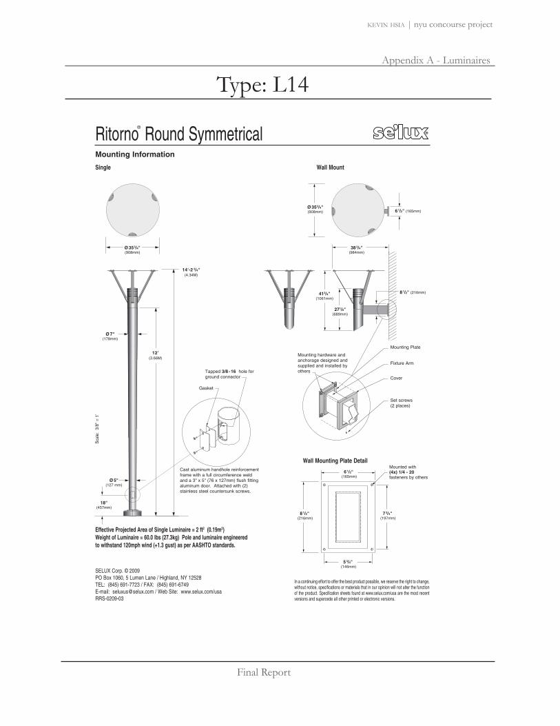
Final Report
Appendix A - Luminaires
kevin hsia | nyu concourse project
Ritorno®
Round Symmetrical
SELUX Corp. © 2009PO Box 1060, 5 Lumen Lane / Highland, NY 12528TEL: (845) 691-7723 / FAX: (845) 691-6749E-mail: [email protected] / Web Site: www.selux.com/usaRRS-0209-03
In a continuing effort to offer the best product possible, we reserve the right to change,without notice, specifications or materials that in our opinion will not alter the functionof the product. Specification sheets found at www.selux.com/usa are the most recentversions and supercede all other printed or electronic versions.
Ø 353/4"(908mm)
383/4"(984mm)
61/2" (165mm)
81/2" (216mm)
Ø 7"(178mm)
Ø 5"(127 mm)
12’(3.66M)
14’-2 3/4"(4.34M)
Effective Projected Area of Single Luminaire = 2 ft2 (0.19m2) Weight of Luminaire = 60.0 lbs (27.3kg) Pole and luminaire engineered to withstand 120mph wind (+1.3 gust) as per AASHTO standards.
Mounting Information
Tapped 3/8 -16 hole forground connector
Gasket
Cast aluminum handhole reinforcementframe with a full circumference weldand a 3" x 5" (76 x 127mm) flush fittingaluminum door. Attached with (2)stainless steel countersunk screws.
Sca
le:
3/8"
= 1
’
413/4"(1061mm)
Ø 353/4"(908mm)
271/8"(689mm)
73/4"(197mm)
81/2"(216mm)
61/2"(165mm)
Mounted with(4x) 1/4 - 20 fasteners by others
53/4"(146mm)
Single Wall Mount
Wall Mounting Plate Detail
Mounting Plate
Mounting hardware andanchorage designed andsupplied and installed byothers
Set screws(2 places)
Cover
Fixture Arm
18"(457mm)
Type: L14

Final Report
Appendix A - Luminaires
kevin hsia | nyu concourse project
Ritorno®
Round Symmetrical
SELUX Corp. © 2009PO Box 1060, 5 Lumen Lane Highland, NY 12528TEL (845) 691-7723 FAX (845) 691-6749E-mail: [email protected] Web Page: www.selux.com/usaRRS-0209-04 (6-49096-00)
9 1/4"(235mm)
Ø 8 1/2" (216mm)Bolt Circle
Hand Hole Location
Ø 4 11/16"(119mm)Conduit Opening
Bolt Circle
1/2" (13mm)for leveling
Galvanized HeavyHex Leveling Nut
Galvanized Heavy HexNut3/4 " x 15"
Galvanized Anchor Bolts
Concrete footingdesigned andsupplied by others
Grout by others
Anchor Bolt Detail
Galvanized Flat Washers
GalvanizedLock Washer
31/4"(82.5mm)
Use caution when setting anchor bolts. Bolts must bevertically straight and centered on dimensions shown.
Note: Adequate drainage must be provided in concrete foundation or grout.
In a continuing effort to offer the best product possible, we reserve the right to change,without notice, specifications or materials that in our opinion will not alter the functionof the product. Specification sheets found at www.selux.com/usa are the most recentversions and supercede all other printed or electronic versions.
OptionsGFCI Receptacle (REC) - GFCI duplex receptaclewith cast base welded to pole and gasketed, provided with weather-proof, self-closing cover; located 36" (915mm) from base of pole, inline with handhole. Receptacle is intended only for portable tools or other portable equipment to be connected to outlet only when attended by operating personnel.
2 13/16" (71mm)
13/16"(21mm)
2 13/16"(71mm)
BC3 Standard Base CoverDie-cast aluminum, two-piecefield installable base cover.
41/2"(112mm)
Ø12 1/2"(316mm)
Ø5"(127mm)
Alternate Mounting Detail
Hei
ght
All Poles are constructed per AASHTOstandards for structural supports for highwaysigns, luminaires and traffic signals as pub-lished in 1975, amended and adopted in1985 and 1994.
A consideration of field conditions such as(but not limited to) wind zone, height, vibra-tion must be given by the designer/specifierfor the appropriate application.
Performance of poles is dependent uponproper support/attachment of pole to ade-quate foundation design. SELUX does notdesign or offer recommendations for foun-dations. EPA values assume that the bot-tom of the pole is at grade level.
Call SELUX (1-800-SELUXCS) if there areany questions, or for any assistance in deter-mining suitability with appropriate fixtures.
Ritorno Reverse Taper Pole (5" to 7")EPA values calculated as per AASHTO LTS4 2001, to include fixture. Consult factory for heights other than 12’.
PoleHeight
Windspeed
70 80 90 100 110 120
10' 16.70 12.34 9.31 7.19 5.62 4.42
12' 13.60 9.86 7.27 5.46 4.11
14' 10.13 7.06 5.02
16' 8.25 5.53
Type: L14
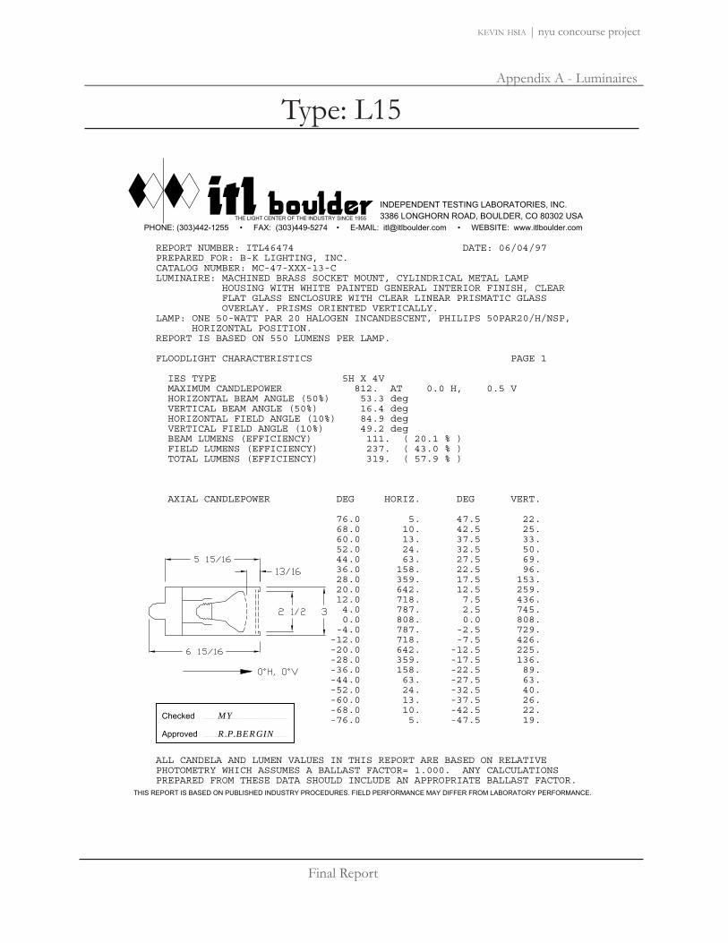
Final Report
Appendix A - Luminaires
kevin hsia | nyu concourse project
REPORT NUMBER: ITL46474 DATE: 06/04/97 PREPARED FOR: B-K LIGHTING, INC. CATALOG NUMBER: MC-47-XXX-13-C LUMINAIRE: MACHINED BRASS SOCKET MOUNT, CYLINDRICAL METAL LAMP HOUSING WITH WHITE PAINTED GENERAL INTERIOR FINISH, CLEAR FLAT GLASS ENCLOSURE WITH CLEAR LINEAR PRISMATIC GLASS OVERLAY. PRISMS ORIENTED VERTICALLY. LAMP: ONE 50-WATT PAR 20 HALOGEN INCANDESCENT, PHILIPS 50PAR20/H/NSP, HORIZONTAL POSITION. REPORT IS BASED ON 550 LUMENS PER LAMP. FLOODLIGHT CHARACTERISTICS PAGE 1 IES TYPE 5H X 4V MAXIMUM CANDLEPOWER 812. AT 0.0 H, 0.5 V HORIZONTAL BEAM ANGLE (50%) 53.3 deg VERTICAL BEAM ANGLE (50%) 16.4 deg HORIZONTAL FIELD ANGLE (10%) 84.9 deg VERTICAL FIELD ANGLE (10%) 49.2 deg BEAM LUMENS (EFFICIENCY) 111. ( 20.1 % ) FIELD LUMENS (EFFICIENCY) 237. ( 43.0 % ) TOTAL LUMENS (EFFICIENCY) 319. ( 57.9 % ) AXIAL CANDLEPOWER DEG HORIZ. DEG VERT. 76.0 5. 47.5 22. 68.0 10. 42.5 25. 60.0 13. 37.5 33. 52.0 24. 32.5 50. 44.0 63. 27.5 69. 36.0 158. 22.5 96. 28.0 359. 17.5 153. 20.0 642. 12.5 259. 12.0 718. 7.5 436. 4.0 787. 2.5 745. 0.0 808. 0.0 808. -4.0 787. -2.5 729. -12.0 718. -7.5 426. -20.0 642. -12.5 225. -28.0 359. -17.5 136. -36.0 158. -22.5 89. -44.0 63. -27.5 63. -52.0 24. -32.5 40. -60.0 13. -37.5 26. -68.0 10. -42.5 22. -76.0 5. -47.5 19. ALL CANDELA AND LUMEN VALUES IN THIS REPORT ARE BASED ON RELATIVE PHOTOMETRY WHICH ASSUMES A BALLAST FACTOR= 1.000. ANY CALCULATIONS PREPARED FROM THESE DATA SHOULD INCLUDE AN APPROPRIATE BALLAST FACTOR.
THE LIGHT CENTER OF THE INDUSTRY SINCE 1955
INDEPENDENT TESTING LABORATORIES, INC. 3386 LONGHORN ROAD, BOULDER, CO 80302 USA
PHONE: (303)442-1255 • FAX: (303)449-5274 • E-MAIL: [email protected] • WEBSITE: www.itlboulder.com
THIS REPORT IS BASED ON PUBLISHED INDUSTRY PROCEDURES. FIELD PERFORMANCE MAY DIFFER FROM LABORATORY PERFORMANCE.
Approved
Checked MY
R.P.BERGIN
Type: L15

Final Report
Appendix A - Luminaires
kevin hsia | nyu concourse project
THE LIGHT CENTER OF THE INDUSTRY SINCE 1955
INDEPENDENT TESTING LABORATORIES, INC. 3386 LONGHORN ROAD, BOULDER, CO 80302 USA
PHONE: (303)442-1255 • FAX: (303)449-5274 • E-MAIL: [email protected] • WEBSITE: www.itlboulder.com
THIS REPORT IS BASED ON PUBLISHED INDUSTRY PROCEDURES. FIELD PERFORMANCE MAY DIFFER FROM LABORATORY PERFORMANCE.
REPORT NUMBER: ITL46474 DATE: 06/04/97 PREPARED FOR: B-K LIGHTING, INC. ISOCANDELA CURVES PAGE 6 AVERAGE OF RIGHT AND LEFT SIDES
-50
-45
-40
-35
-30
-25
-20
-15
-10
-5
0
5
10
15
20
25
30
35
40
45
50
0
0
5
5
10
10
15
15
20
20
25
25
30
30
35
35
40
40
45
45
50
50
700
600
500
406 (= 50% MAX)
300
200
81 (= 10% MAX)
Type: L15

Final Report
Appendix A - Luminaires
kevin hsia | nyu concourse project
E Cylinder Facade luminairedirect lighting for low-voltage halogen lamps
54 36666 666666
34666666
34666666
MRC16Size 230°
N äDry
öDamp
üWet
ÖOutdoor
85022.023 Graphit mMRC16 50W 12V GU5.3 10°MRC16 50W 12V GU5.3 36°
Product descriptionHousing and wall plate: corrosion-resistant, cast aluminum, No-rinsesurface treatment. Double powder-coated. Optimized surface for re-duced accumulation of dirt. Hous-ing removable for lamp replace-ment. Tamper-proof screw.2 cable entries. Through-wiringpossible. 3-pole terminal block.Magnetic transformer 120/12V,60Hz.Reflector: aluminum, silver, specu-lar anodized. Softec lens.Lower safety glass.Suitable for wet location (IP65):dust-proof and water jet-proof.Weight 5.64lbs / 2.56kg
30° 30°
60° 60°
10000 cd30° 30°
60° 60°
2000 cd
MRC16 50W 12V GU5.3 10°
h(ft) E(fc) D10°
3 1000 0’6"6 250 1’1"9 111 1’7"12 62 2’1"15 40 2’7"
MRC16 50W 12V GU5.3 36°
h(ft) E(fc) D36°
3 204 1’11"6 51 3’11"9 23 5’10"12 13 7’10"15 8 9’9"
ERCO Lighting Inc.160 Raritan Center ParkwaySuite 10Edison, NJ 08837USATel.: +1 732 225 8856Fax: +1 732 225 [email protected]
Technical Region: 120V/60HzEdition: 12.02.2008Please download latest version fromwww.erco.com/85022.023
1/1
Type: L16

Final Report
Appendix A - Luminaires
kevin hsia | nyu concourse project
DAIFUKU DESIGNSLITE BOX, LITE CUBE
248
Lámparas-asientos en polietileno blanco. Aptos para exterior e interior. Aplicable para terrazas y jardines. Equipados con cable 9 m.
BOMBILLAS*- LITE CUBE: 1x7 W máx. (E-27 bajo consumo). - LITE BOX: 4x7 W máx. (E-27 bajo consumo). *Colores: blanco (cálido 2700º K), rojo, verde, amarillo y azul.
ACABADOSPolietileno blanco.
Lights-seats in white polyethylene designed for indoor and outdoor use, adapted for gardens and terraces. Equipped with 9 m of cable.
BULBS*- LITE CUBE: 1x7 W max. (E-27 low energy). - LITE BOX: 4x7 W max. (E-27 low energy). *Colours: white (warm 2700º K), red, green, yellow and blue.
FINISHESWhite polyethylene.
Sitzhocker und Bodenleuchte für den Innen-und Aussenraum. Kabellänge 9 Meter.
LAMPE*- LITE CUBE: 1x7 W max. (Kompakleuchtstoff- lampe E-27).- LITE BOX: 4x7 W max. (Kompakleuchtstofflampe E-27).*Lichtfarbe: weiß (warm 2700º K), rot, grün, gelb oder blau nach Wahl.
OBERFLÄCHEPolyethylen opalweiß.
43
50
50
LITE CUBE
Apto exteriores.For outdoor use.Für Außenanwendung.
LITE CUBE: IP 65.LITE BOX: IP 66.
90
LITE BOX
9032
Type: L17

Final Report
Appendix A - Luminaires
kevin hsia | nyu concourse project
www.ilight-tech.com
iLight Technologies • 118 South Clinton, Suite 370 • Chicago, IL 60661 • T 312.876.8630 • F 312.876.8631 • www.ilight-tech.com
Color Temperatures (+/- 10%)• 3500°K• 4500°K• 6500°K
Diffuser Color• Light amber hue (when not illuminated)
Lengths Available• 2’, 4’, 6’, 8’ (610 mm, 1220 mm, 1830 mm,
2440 mm)• 22” field cuttable pieces• 9’’ x 9’’ illuminated outside corner pieces• Factory custom lengths available to the
nearest 1”1
• Factory convex or concave bends to minimuminside radius of 5’’
1
• Factory “easy bends” to 3/16” radius1
• Gentle field bends to a 48” radius
Plexineon White 1X Series PRODUCT SUMMARY
ORDERING INFORMATION
PRODUCT FEATURES
• Three Kelvin temperatures• Energy efficient• Long lifetime• Stable and consistent color temperature• Low voltage• Easy to install• Cool to the touch• For use as exterior or interior accent,
interior indirect, cove, stage and shelflighting, signage and more
Power Supply
• Primary voltage: 120 or 120-277 depending on model• Secondary voltage: 24VDC 4.1 A Max• Maximum illumination length of a single LED power supply:
32 feet or 9.8 meters
Power Supply Tips• 20% maximum overage for breaker for primary current draw• Do not plug multiple power supplies into one run of
Plexineon• All iLight power supplies should be on an independent circuit• Recommend surge protection upstream from power supply• Verify correct voltage prior to wiring to non-switching
power supplies
Low Voltage CableMaximum distance of low voltage cable in any given run:• 14 AWG: 40 feet or 12.19 meters• 12 AWG: 60 feet or 18.29 meters• 10 AWG: 100 feet or 30.48 meters
• Class 2 24 VDC, 100 Watts - must be supplied by iLight
PNW1V2-0108
For the most current technical information,please refer to www.ilight-tech.com.
CLASS
T = Trim 24 = 24V S = Silver
VOLTAGE COLOR HOUSING LENGTH CHANNEL VERSION
00
T 24 S 00
2F = 2 Feet4F = 4 Feet6F = 6 Feet8F = 8 FeetCL = Custom LengthTT = 22” Cuttable9M = Outside CornerBE= Bend - Easy BN = Bend - ConvexBV= Bend - Concave
SC = StainlessSteel Channel
NC = No Channel
W35 = 3500°KW45 = 4500°KW65 = 6500°K
1. Drawings required for production
Type: L18

Final Report
Appendix A - Luminaires
kevin hsia | nyu concourse project
2
www.ilight-tech.com
Plexineon White 1X Series TECHNICAL INFORMATION
Width & Height Housing• 0.55”(14mm) w x 1.35’’(34mm) h (with c-channel)• UV and impact resistant acrylic diffuser• UV resistant plastic channel• Stainless steel c-channel for mechanical
support
Minimum Piece Spacing• Linear (end to end) = 3/8”• Parallel (edge to edge) = 1”
Mounting• Stainless steel spring mounted clips• Clips to be 2” in from end of piece and no more
than 2’ maximum between clips
Power Supply Weight• Electronic (Advance) Power Supply is 2 lbs.• Outdoor Magnetic Hybrid Power Supply is 9 lbs.
Power Supply Dimensions• Electronic (Advance) = 91/2’’ x 11/4’’ x 13/4’’• Outdoor Magnetic Hybrid= 85/8’’ x 31/2’’ x 41/4’’
Load Voltage24 V DC
Load Current108 mA/foot at 24VDC
Maximum Run Length32 feet with an iLight approved power supply
DC Cable• 14 AWG, PVC/Nylon Type TC 600 Volt power and
control cable or equivalent • FT-4 fire rating• Class 2 wiring system• Connectors: Molex Splashproof - JIS D0203 S2
Electrical Tips• Only use iLight approved transformers• Do not cut non-cuttable pieces
ME
CH
AN
ICA
L W
ITH
OU
TE
XT
RU
SIO
NE
LEC
TR
ICA
L
iLight Technologies • 118 South Clinton, Suite 370 • Chicago, IL 60661 • T 312.876.8630 • F 312.876.8631 • www.ilight-tech.com
EN
VIR
ON
ME
NTA
L Operating Temperature Range -25°C to 50°C (-13°F to 122°F)
Storage Temperature Range-25°C to 75°C (-13°F to 167°F)
Certification• Plexineon is MetLabs listed. Metlabs is a
Nationally Recognized Testing Laboratory(NTRL). Complies with UL 1598 and CSA c22.2 No. 250 in Luminaire,Wet listed.
• Power Supplies are RU listed. RU stands forRecognized Components by UnderwritersLaboratory.
PNW1V2-0108
*The minimum space for ventilation surrounding thePlexineon product is 1.0”. This distance should be maintainedon the three sides, left and right of the product as well as infront of product. Other configurations subject to specificapplication testing.
Type: L18

Final Report
Appendix A - Luminaires
kevin hsia | nyu concourse project
Type: L19
eW Cove PowercoreAn EssentialWhite™ Product
eW® Cove Powercore is a dimmable, line-voltage, linear light fixture for common medium-luminance alcove applications. Its low profile makes it a perfect choice for many retail, exhibit, hospitality, and architectural interior settings.
Runs of up to 100 linear feet on a single circuit are possible as well as very smooth dimming. An integrated mounting bracket, end-to-end connections, and an optional mounting track ensure a simple, fast installation.
• Integral mounting bracket with 180º rotation• Low power consumption (<6 W start-up; 4.5 W
steady-state)• End-to-end connections• Color temperatures of 2800 K and 4200 K• Sizes of 12 in (305 mm) and 6 in (152 mm)• Up to 100 12 Inch or 150 6 Inch fixtures may be
used in a series
• Powercore® technology supports 100, 120, and 230 VAC line voltage for simple installations and long runs
• DIMand™ technology provides smooth dimming capability with ELV-type dimmers
• Optibin® technology ensures uniform light quality

Final Report
Appendix A - Luminaires
kevin hsia | nyu concourse project
Type: L19
Philips Solid-State Lighting Solutions, Inc. • 3 Burlington Woods Drive • Burlington, MA 01803 • USATel: 617.423.9999 • Toll Free: 888.385.5742 • Fax: 617.423.9998 • www.colorkinetics.com
eW Cove Powercore Specifications 3
eW Cove Powercore SpecificationsSpecifications are subject to change without notice.
6-Inch Fixture 12-Inch Fixture
Length 6 in (152 mm) 12 in (305 mm)
Width 1.25 in (32 mm) (tube diameter)
Height 1.37 in (35 mm)
Weight 3 oz. (85 g) 5 oz. (142 g)
Source High-efficacy (>40 LPW ), high-brightness LEDs that enable eW Cove Powercore installations to meet California Title 24 requirements.
Color Temperature 2800 K (+375/-300) or 4200 K (+400/-500)
LEDs Per Fixture 3 5
CRI 71: 2800 K 79: 4200 K
71: 2800 K 77: 4200 K
Total Output (Lumens) 64: 2800 K 72: 4200 K
135: 2800 K 177: 4200 K
Efficacy (Lm/W) 30.7: 2800 K 39.3: 4200 K
30.7: 2800 K 39.3: 4200 K
Beam Angle 110º x 110º
Mixing Distance 2 in (51 mm) to uniform light
Housing Charcoal gray, UL-recognized, injection-molded plastic.
Lens Clear polycarbonate
Environment UL Dry; CE IP20
Inter-fixture Connectors IEC 15 A (max) with C13 plug
Maximum Run Length 150 fixtures 100 fixtures
Leader Cable 2-pole, 2-wire, 15 A (sold separately)
Listings UL/CUL (120 VAC), CE
Control Line switches or ELV (electronic low voltage) commercially-available dimmers.
Line Voltage 100, 120, or 230 VAC
Power Consumption 4 W max. at start-up2.2 W max. steady state
6 W max. at start-up4.5 W max. steady state
Temperature Range -4°F – 122°F (-20°C – 50°C) operating temperature
Humidity Range 0 – 95% non-condensing
LED Source Life 50,000 hours, based on LED manufacturers’ test data

Final Report
Appendix A - Luminaires
kevin hsia | nyu concourse project
Type: L196 eW Cove Powercore Data Sheet
Philips Solid-State Lighting Solutions, Inc. • 3 Burlington Woods Drive • Burlington, MA 01803 • USATel: 617.423.9999 • Toll Free: 888.385.5742 • Fax: 617.423.9998 • www.colorkinetics.com
eW Cove Powercore 12-Inch 4200 K PhotometricsPhotometric data in each illustration is based on independent testing lab results. IES data is available at http://www.colorkinetics.com/support/ies. The tested fix-ture had these specifications:
Voltage 120 VAC
Optics None
Lens Optically clear polycarbonate
Source 5 LEDs
Beam Angle 110° x 110°
Distribution Symmetric direct illumination
Candle Power DistributionThe dashed line indicates that 34 candela is 50% of peak.
0
-9017 34 50 67
90
39 fc(419.8 lux)
13.7 fc(147.7 lux)
6.7 fc(72.1 lux)
4’ 3’ 2’ 1’
110°
3.9 fc(42 lux)
122 cm 91 cm 61 cm 30 cm
Plan
e us
ed f
or lu
min
ance
dis
trib
utio
n p
lot.
1’
0’
1’
2’
2’
1’ 0’ 1’ 2’2’
61cm
30 cm
30 cm
0 cm
61 cm
61cm30 cm30 cm 0 cm61 cm
1.5 (16) 3 (32) 5 (54) 9 (97) 15 (161) 25 (269)
lluminance Distribution This illustration shows the plane 1 ft (305 mm) from the fixture. Data is in footcandles and (lux).
Illuminance Beam Angle This illustration shows measurement of the center beam and the fixture’s angle. Data is in footcandles and (lux).

Final Report
Appendix A - Luminaires
kevin hsia | nyu concourse project
Type: L21
Lightolier is a Philips group brand
Architectural Decorative Vetro Downlight D01Page 1 of 2 Evolution, Low Voltage
We reserve the right to change details of design, materials and finish.
Job Information Type:
Job Name:
Cat. No.:
Lamp(s):
Notes:
Features1. Decorative Element: Solid high temp, UV resistant composite with open
2. Aluminum Insert: Satin Aluminum ring is mechanically inserted in composite to create drama and intrigue in the element.
3. Die Cast Ring:finish matches diameter of decorative element for a flangeless appearance.
4. Integral Reflector:image. Decorative Element is mechanically attached to reflector via die cast
5. Cover Glass:Evolution contains high temperature perimeter frost.
6. Trim Kit: ship complete.
7. Frame-In Kit: details.
MechanicalDecorative element is mechanically secured to the die cast construction ring and the integral reflector from the factory.
Labels
C
B
A
Decorative Element/Trim Kit Catalog No.
Frame-In Kit Lamping DimensionsA B C
3" Evolution D3MR01 C3LV; C3AICLV; C3ALV; C3LVE1; C3LVE2; C3ALVE1; C3AICLVE1
4" Evolution D4MR01
3
1
2
2 Piece Ordering System, Example: D3MR01 + C3LV

Final Report
Appendix A - Luminaires
kevin hsia | nyu concourse project
Type: L21
Lightolier is a Philips group brand
Job Information Type:
We reserve the right to change details of design, materials and finish.
Architectural Decorative Vetro Downlight D01Page 2 of 2 Evolution, Low Voltage
15000°
30°
60°
90°
500
1000
Candlepower Summary
Angle Mean CP Lumens0
10
20
30 2713
1716 13
1360 13
12 1270 10
10 10
10
Zonal Lumens and Percentages
Zone Lumens % Lamp %Luminaire
100.007.17 12.62
320 .00 .00
100.00
Prepared For:Lightolier Fall River, MA
Coefficients of Utilization
Ceiling 70% 30% 10%Wall 70 30 10 70 30 10 30 10 30 10 30 10 0RCR
Room
Cav
ity R
atio
0 .66 .66 .66 .66 .63 .63 .63 .60 .60 .601 .63 .62 .61 .63 .62 .61 .60 .602 .62 .60 .613 .60
67
10
30°
1000
2000
0°
60°
90°
500
1500
Candlepower Summary
Angle Mean CP Lumens0
1761 16010
20170
3017
1716 12
13 1260 13
12 1270 11
10 111010 11
Zonal Lumens and Percentages
Zone Lumens % Lamp %Luminaire
600 100.007.22
330 .00 .00
600 100.00
Certified test report no. FR
Prepared For:Lightolier Fall River, MA
Coefficients of Utilization
Ceiling 70% 30% 10%Wall 70 30 10 70 30 10 30 10 30 10 30 10 0RCR
Room
Cav
ity R
atio
0 .77 .77 .771 .77 .77 .76 .73 .73 .722 .76 .76 .73 .73 .71 .72 .71 .703 .76 .71 .73 .71 .72 .70 .72 .70 .71 .67
.71 .77 .73 .70 .72 .67 .70 .67 .67 .66.76 .71 .66 .71 .66 .67 .66 .67 .63
6 .66 .73 .66 .63 .67 .63 .66 .62 .627 .72 .67 .62 .71 .67 .62 .66 .63 .62 .63 .61 .62 .61 .60
.70 .62 .60 .62 .60 .62 .60 .61 .60 .63 .61.61 .63 .61 .63 .60 .62 .60 .62 .60
10 .67 .62 .66 .62 .61 .61 .61

Final Report
Appendix A - Luminaires
kevin hsia | nyu concourse project
Type: L22Be
am S
prea
dsLe
ngth
sDi
men
sion
sPo
wer
Sup
ply
(100
W D
RIVE
R)
up to 12’-0” (3.6m)Single run lengthsNTE 7.5’ (2.3m) or(5) 18” fixtures
combined fixturerun lengths up to42’-0” (12.8m).Single run lengthsNTE 10.5’ (3.2m)or (7) 18” fixtures.
Applicationio Lighting’s line series 1.5 is approximately 1.5" in diameter. UL listed for wet locations, this LED-based linear floodlight produces functional luminous intensities for lighting bridges and building facades. Ideal for grazing and accent illumination, individual units may be placed end to end to create continuous rows without obvious shadows between fixtures. LEDs are similar to halogen light sources in that they are point sources that can reveal superior definition to textural surfaces and sparkle to reflective surfaces.
series 1.5 is a low voltage linear luminaire that may be ordered in incremental nominal lengths that include: 18" and 36". Optional beam spreads along the perpendicular axis of the fixture include 10°, 45° and 65°. io ensures that each LED is driven with the proper current and voltage, which enables the average rated life to be 50,000 hours at 70% of lamp lumen output. To ensure proper performance, interior architectural details should allow for ventilation and air flow around the fixture. Ambient temperature surrounding the fixture shall not exceed 120˚F (48.9˚C).
lineTM 1.5
Light Outputline series 1.5 is available with two lumen outputs for white light only. Red, green and blue are available in high output only. IES format files may be obtained from the factory or downloaded from www.iolighting.com.
Standard Output: High Output: 3000K White: 34 lms/ft 3000K White: 170 lms/ft 5000K White: 40 lms/ft 5000K White: 230 lms/ft
Refer to light output tables for footcandle values at various distances. IES files will be available third quarter ’07.
ConstructionThe light weight, yet durable extruded aluminum housing provides recommended heat sink requirements for LEDs. Patented precision optic assembly is composed of a customized acrylic material that offers very high transmissivity, UV stability and excellent longevity. series 1.5 is UL listed for wet locations.
Electrical8'-0' 18 AWG, 600 volt TFFN rated power cords are supplied with plug connector. Injection molded end cap is designed to receive both the plug electrical connector and an interconnect for daisy chain. 24 volt 100 watt power supply will be provided as a standard. See daisy chain and remote distance requirements in chart on the lower left corner of this specification sheet.
Power supply and dimming module must be specified separately. For detailed information, consult io website or io representative for specification sheets.
Power ConsumptionStandard Output : 2.1 w/ft High Output: 7.6 w/ft
Power consumption does not include power supply losses. Consult io driver specification sheets (at www.iolighting.com) for losses associated with each driver option.
FinishAnodized aluminum finish is standard. Custom finishes may be available upon request.
io Lighting 370 Corporate Woods Parkway Vernon Hills, IL 60061-3107 T 847.735.7000 F 847.735.7001 E [email protected] W iolighting.com1

Final Report
Appendix A - Luminaires
kevin hsia | nyu concourse project
Type: L22
io Lighting 370 Corporate Woods Parkway Vernon Hills, IL 60061-3107 T 847.735.7000 F 847.735.7001 E [email protected] W iolighting.com2
Lig
ht O
utpu
tEl
ectr
ical
Fee
dsM
ount
ing
Optio
ns
IES format photometrics may be downloaded from www.iolighting.com
LIGHT OUTPUT CONVERSION TABLE
2. End Feed Interconnector
(For continuous row mounting)
Interconnect plug connection is
used for daisy chaining.
NOTE: Footcandle values based on Warm White H.O.
3. Right Side Feed
IES format photometrics may be downloaded from www.iolighting.com
LIGHT OUTPUT CONVERSION TABLE
2. End Feed Interconnector
(For continuous row mounting)
Interconnect plug connection is
used for daisy chaining.
3. Right Side Feed
1. LIGHT OUTPUT10 1.5 S.O. or H.O.
2. LOCATIONE Exterior
3. COLOR3K White 3000K(Standard)(1)
3KHO White 3000K (High Output)(1)
5K White 5000K(Standard)(1)
5KHO White 5000K (High Output)(1)
R Red(2) G Green(2)
B Blue(2)
4. DISTRIBUTION10 10 Degree45 45 Degree65 65 Degree
5. MOUNTING100 SurfaceNote: Universal mounting bracket may be used for all mounting orientations.Set screw locks in aim angle.
6. FINISH1 Anodized Aluminum2 Anodized Custom Color
7. LENGTH UNITS (ACTUAL)18 18" (18.25") IP56 Lens face up or down3
36 36" (35.25") IP55 Lens face down3
FOR CONTINUOUS ROWSpecify length (e.g., 96'-0")Note: Overall length must be divisible by 18"
8. ELECTRICAL FEED2 End Feed3 Right Side FeedNote: For straight continuous rows fed by one driver, interconnects will be supplied as required
9. VOLTAGE / DIMMING1 120v2 277v3 120v w/dim4 277v w/dim5 Other
10. SPECIFY DRIVER / DIMMINGNote: If left blank, io will supply 100 watt drivers. Download Power Supply specification sheet from www.iolighting.com
0 10 E
io 1 2 3 4 5 6 7 8
Orde
r Co
de
9
Footnotes1. White light variance between LEDs within a single fixture will not exceed +/- 200k.2. Refer to conversion table for output. High Output only (7.6 w/ft).3. 18" lengths may be installed in face up or face down applications. 36" lengths may be
installed in face down applications only.Foot
note
s
10
IP55, IP56 and UL Listed
for wet locations.
line series 1.5 is not rated for submersible applications. line 1.5 should not be mounted in conditions where there is any standing water whatsoever.
1.5 may be rotated within the bracket for field adjustable aiming.
Set screw locks fixture into place.
2X ø.144(For #6 screw)
.75"1.50"
L1.bk.adj

Final Report
Appendix B - Lamps
kevin hsia | nyu concourse project
Lamps: 28W T5
T5 Mini Bipin
For more complete product information visit www.sylvania.com Symbols/Footnotes on page 139-143
121
PENTRON® T5 LAMPSPENTRON® High Performance T5 Lamps45 Avg Approx Lumens |
Nominal Avg Initial Mean |Nominal Length MOL Product Pkg Rated CCT @25°C/77°F Symbols & |Wattage Bulb (in) (in) Base Number Ordering Abbreviation Qty Life (hrs) (K) CRI (@35°C/95°F) Footnotes |21 T5 36 34 Mini Bipin 20924 FP21/841/ECO 40 20000 4100 82 1890 1767 1,2,6,
2100 1953 8,9,11
28 T5 48 45.8 Mini Bipin 20838 FP28/60[RED] 40 10000 2100 1,2,8,9,11
20839 FP28/66[GREEN] 40 10000 3500 1,2,8,9,11
20840 FP28/67[BLUE] 40 10000 700 1,2,8,9,11
20836 FP28/830 40 20000 3000 82 2600 2418 1,2,8,9,112900 2697
20868 FP28/830/ECO 40 20000 3000 82 2600 2418 1,2,6,2900 2697 8,9,11
20841 FP28/835 40 20000 3500 82 2600 2418 1,2,8,9,112900 2697
20901 FP28/835/ECO 40 20000 3500 82 2600 2418 1,2,6,2900 2697 8,9,11
20842 FP28/841 40 20000 4100 82 2600 2418 1,2,8,9,112900 2697
20902 FP28/841/ECO 40 20000 4100 82 2600 2418 1,2,6,2900 2697 8,9,11
35 T5 60 57.6 Mini Bipin 20843 FP35/830 40 20000 3000 82 3300 3069 1,2,8,9,113650 3394
20925 FP35/830/ECO 40 20000 3000 82 3300 3069 1,2,6,3650 3394 8,9,11
20844 FP35/835 40 20000 3500 82 3300 3069 1,2,8,9,113650 3394
20926 FP35/835/ECO 40 20000 3500 82 3300 3069 1,2,6,3650 3394 8,9,11
20845 FP35/841 40 20000 4100 82 3300 3069 1,2,8,9,113650 3394
20927 FP35/841/ECO 40 20000 4100 82 3300 3069 1,2,6,3650 3394 8,9,11
PENTRON® High Output, High Performance T5 Lamps45 Avg Approx Lumens |
Nominal Avg Initial Mean |Nominal Length MOL Product Pkg Rated CCT @25°C/77°F Symbols & |Wattage Bulb (in) (in) Base Number Ordering Abbreviation Qty Life (hrs) (K) CRI (@35°C/95°F) Footnotes |24 T5 24 22.2 Mini Bipin 20846 FP24/830/HO 40 20000 3000 82 1750 1627 1,2,8,9,11
2000 1860
20928 FP24/830/HO/ECO 40 20000 3000 82 1750 1627 1,2,6,2000 1860 8,9,11
20852 FP24/835/HO 40 20000 3500 82 1750 1627 1,2,8,9,112000 1860
20929 FP24/835/HO/ECO 40 20000 3500 82 1760 1627 1,2,6,2000 1860 8,9,11
20853 FP24/841/HO 40 20000 4100 82 1750 1627 1,2,8,9,112000 1860
20931 FP24/841/HO/ECO 40 20000 4100 82 1760 1627 1,2,6,2000 1860 8,9,11
39 T5 36 34 Mini Bipin 20854 FP39/830/HO 40 20000 3000 82 3100 2883 1,2,8,9,113500 3255
FLUORESCENT

Final Report
Appendix B - Lamps
kevin hsia | nyu concourse project
Lamps: 24W T5
T5 Mini Bipin
For more complete product information visit www.sylvania.com Symbols/Footnotes on page 139-143
121
PENTRON® T5 LAMPSPENTRON® High Performance T5 Lamps45 Avg Approx Lumens |
Nominal Avg Initial Mean |Nominal Length MOL Product Pkg Rated CCT @25°C/77°F Symbols & |Wattage Bulb (in) (in) Base Number Ordering Abbreviation Qty Life (hrs) (K) CRI (@35°C/95°F) Footnotes |21 T5 36 34 Mini Bipin 20924 FP21/841/ECO 40 20000 4100 82 1890 1767 1,2,6,
2100 1953 8,9,11
28 T5 48 45.8 Mini Bipin 20838 FP28/60[RED] 40 10000 2100 1,2,8,9,11
20839 FP28/66[GREEN] 40 10000 3500 1,2,8,9,11
20840 FP28/67[BLUE] 40 10000 700 1,2,8,9,11
20836 FP28/830 40 20000 3000 82 2600 2418 1,2,8,9,112900 2697
20868 FP28/830/ECO 40 20000 3000 82 2600 2418 1,2,6,2900 2697 8,9,11
20841 FP28/835 40 20000 3500 82 2600 2418 1,2,8,9,112900 2697
20901 FP28/835/ECO 40 20000 3500 82 2600 2418 1,2,6,2900 2697 8,9,11
20842 FP28/841 40 20000 4100 82 2600 2418 1,2,8,9,112900 2697
20902 FP28/841/ECO 40 20000 4100 82 2600 2418 1,2,6,2900 2697 8,9,11
35 T5 60 57.6 Mini Bipin 20843 FP35/830 40 20000 3000 82 3300 3069 1,2,8,9,113650 3394
20925 FP35/830/ECO 40 20000 3000 82 3300 3069 1,2,6,3650 3394 8,9,11
20844 FP35/835 40 20000 3500 82 3300 3069 1,2,8,9,113650 3394
20926 FP35/835/ECO 40 20000 3500 82 3300 3069 1,2,6,3650 3394 8,9,11
20845 FP35/841 40 20000 4100 82 3300 3069 1,2,8,9,113650 3394
20927 FP35/841/ECO 40 20000 4100 82 3300 3069 1,2,6,3650 3394 8,9,11
PENTRON® High Output, High Performance T5 Lamps45 Avg Approx Lumens |
Nominal Avg Initial Mean |Nominal Length MOL Product Pkg Rated CCT @25°C/77°F Symbols & |Wattage Bulb (in) (in) Base Number Ordering Abbreviation Qty Life (hrs) (K) CRI (@35°C/95°F) Footnotes |24 T5 24 22.2 Mini Bipin 20846 FP24/830/HO 40 20000 3000 82 1750 1627 1,2,8,9,11
2000 1860
20928 FP24/830/HO/ECO 40 20000 3000 82 1750 1627 1,2,6,2000 1860 8,9,11
20852 FP24/835/HO 40 20000 3500 82 1750 1627 1,2,8,9,112000 1860
20929 FP24/835/HO/ECO 40 20000 3500 82 1760 1627 1,2,6,2000 1860 8,9,11
20853 FP24/841/HO 40 20000 4100 82 1750 1627 1,2,8,9,112000 1860
20931 FP24/841/HO/ECO 40 20000 4100 82 1760 1627 1,2,6,2000 1860 8,9,11
39 T5 36 34 Mini Bipin 20854 FP39/830/HO 40 20000 3000 82 3100 2883 1,2,8,9,113500 3255
FLUORESCENT

Final Report
Appendix B - Lamps
kevin hsia | nyu concourse project
Lamps: 13W CFL
DULUX® S/E DULUX® D
For more complete product information visit www.sylvania.com Symbols/Footnotes on page 139-143
106
DULUX® S/E 4-PIN COMPACT FLUORESCENT LAMPSfor Dimming and Electronic Ballast
42 Avg Avg Approx Lumens |Nominal MOL Product NEMA Pkg Rated CCT Initial Mean Symbols & |Wattage Bulb (in) (mm) Base Number Ordering Abbreviation Generic Designation Qty Life (hrs) (K) CRI @25°C/77°F Footnotes |5 T4 3.4 85 2G7 20311 CF5DS/E/827 CFT5W/2G7/827 50 10000 2700 82 230 198 1,2,3,8,9
20315 CF5DS/E/841 CFT5W/2G7/841 50 10000 4100 82 230 198 1,2,3,8,9
7 T4 4.5 115 2G7 20312 CF7DS/E/827 CFT7W/2G7/827 50 10000 2700 82 400 344 1,2,3,8,9
20316 CF7DS/E/841 CFT7W/2G7/841 50 10000 4100 82 400 344 1,2,3,8,9
9 T4 5.7 145 2G7 20313 CF9DS/E/827 CFT9W/2G7/827 50 10000 2700 82 580 499 1,2,3,8,9
20317 CF9DS/E/841 CFT9W/2G7/841 50 10000 4100 82 580 499 1,2,3,8,9
13 T4 6.2 157 2GX7 20314 CF13DS/E/827 CFT13W/2GX7/827 50 10000 2700 82 800 688 1,2,3,8,9
20284 CF13DS/E/830 CFT13W/2GX7/830 50 10000 3000 82 800 688 1,2,3,8,9
20318 CF13DS/E/841 CFT13W/2GX7/841 50 10000 4100 82 800 688 1,2,3,8,9
DULUX® D PREHEAT 2-PIN ECOLOGIC® COMPACT FLUORESCENT LAMPSwith Starter in Lamp Base for Magnetic Ballast
42 Avg Avg Approx Lumens |Nominal MOL Product NEMA Pkg Rated CCT Initial Mean Symbols & |Wattage Bulb (in) (mm) Base Number Ordering Abbreviation Generic Designation Qty Life (hrs) (K) CRI @25°C/77°F Footnotes |9 T4 4.3 110 G23-2 20537 CF9DD/827/RP CFQ9W/G23/827 10 10000 2700 82 525 452 1,2,3,
4,5,6
20689 CF9DD/827 CFQ9W/G23/827 50 10000 2700 82 525 452 1,2,3,4,5,6
20783 CF9DD/830 CFQ9W/G23/830 50 10000 3000 82 525 452 1,2,3,4,5,6
20690 CF9DD/835 CFQ9W/G23/835 50 10000 3500 82 525 452 1,2,3,4,5,6
13 T4 4.6 118 GX23-2 20538 CF13DD/827/RP CFQ13W/GX23/827 10 10000 2700 82 780 671 1,2,3,4,5,6
20691 CF13DD/827 CFQ13W/GX23/827 50 10000 2700 82 780 671 1,2,3,4,5,6
20705 CF13DD/830 CFQ13W/GX23/830 50 10000 3000 82 780 671 1,2,3,4,5,6
20692 CF13DD/835 CFQ13W/GX23/835 50 10000 3500 82 780 671 1,2,3,4,5,6
20708 CF13DD/841 CFQ13W/GX23/841 50 10000 4100 82 780 671 1,2,3,4,5,6
18 T4 6.0 153 G24D-2 20676 CF18DD/827 CFQ18W/G24D/827 50 10000 2700 82 1150 1075 1,2,3,4,5,6
20709 CF18DD/830 CFQ18W/G24D/830 50 10000 3000 82 1150 1075 1,2,3,4,5,6
20677 CF18DD/835 CFQ18W/G24D/835 50 10000 3500 82 1150 1075 1,2,3,4,5,6
20678 CF18DD/841 CFQ18W/G24D/841 50 10000 4100 82 1150 1075 1,2,3,4,5,6
26 T4 6.8 173 G24D-3 20679 CF26DD/827 CFQ26W/G24D/827 50 10000 2700 82 1710 1548 1,2,3,4,5,6
20710 CF26DD/830 CFQ26W/G24D/830 50 10000 3000 82 1710 1548 1,2,3,4,5,6
20680 CF26DD/835 CFQ26W/G24D/835 50 10000 3500 82 1710 1548 1,2,3,4,5,6
FLUORESCENT
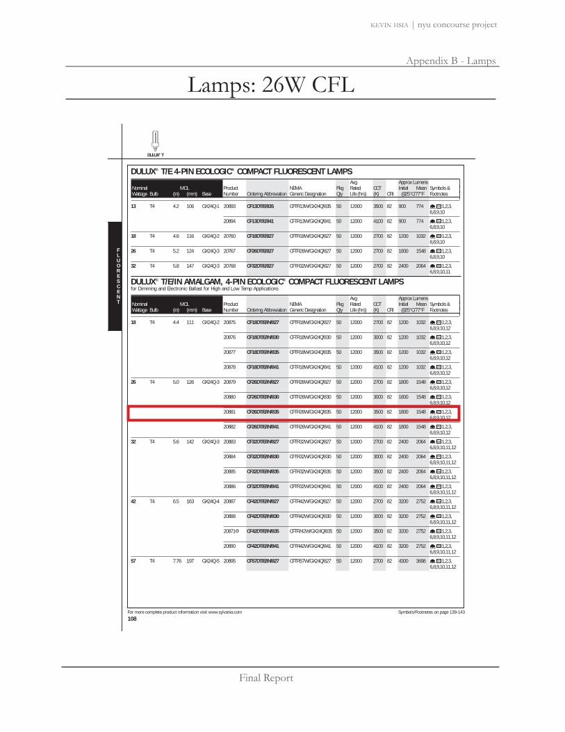
Final Report
Appendix B - Lamps
kevin hsia | nyu concourse project
Lamps: 26W CFL
DULUX® T
For more complete product information visit www.sylvania.com Symbols/Footnotes on page 139-143
108
DULUX® T/E 4-PIN ECOLOGIC® COMPACT FLUORESCENT LAMPS42 Avg Avg Approx Lumens |Nominal MOL Product NEMA Pkg Rated CCT Initial Mean Symbols & |Wattage Bulb (in) (mm) Base Number Ordering Abbreviation Generic Designation Qty Life (hrs) (K) CRI @25°C/77°F Footnotes |13 T4 4.2 106 GX24Q-1 20893 CF13DT/E/835 CFTR13W/GX24Q/835 50 12000 3500 82 900 774 1,2,3,
6,8,9,10
20894 CF13DT/E/841 CFTR13W/GX24Q/841 50 12000 4100 82 900 774 1,2,3,6,8,9,10
18 T4 4.6 116 GX24Q-2 20760 CF18DT/E/827 CFTR18W/GX24Q/827 50 12000 2700 82 1200 1032 1,2,3,6,8,9,10
26 T4 5.2 124 GX24Q-3 20767 CF26DT/E/827 CFTR26W/GX24Q/827 50 12000 2700 82 1800 1548 1,2,3,6,8,9,10
32 T4 5.8 147 GX24Q-3 20768 CF32DT/E/827 CFTR32W/GX24Q/827 50 12000 2700 82 2400 2064 1,2,3,6,8,9,10,11
DULUX® T/E/IN AMALGAM, 4-PIN ECOLOGIC® COMPACT FLUORESCENT LAMPSfor Dimming and Electronic Ballast for High and Low Temp Applications
42 Avg Avg Approx Lumens |Nominal MOL Product NEMA Pkg Rated CCT Initial Mean Symbols & |Wattage Bulb (in) (mm) Base Number Ordering Abbreviation Generic Designation Qty Life (hrs) (K) CRI @25°C/77°F Footnotes |18 T4 4.4 111 GX24Q-2 20875 CF18DT/E/IN/827 CFTR18W/GX24Q/827 50 12000 2700 82 1200 1032 1,2,3,
6,8,9,10,12
20876 CF18DT/E/IN/830 CFTR18W/GX24Q/830 50 12000 3000 82 1200 1032 1,2,3,6,8,9,10,12
20877 CF18DT/E/IN/835 CFTR18W/GX24Q/835 50 12000 3500 82 1200 1032 1,2,3,6,8,9,10,12
20878 CF18DT/E/IN/841 CFTR18W/GX24Q/841 50 12000 4100 82 1200 1032 1,2,3,6,8,9,10,12
26 T4 5.0 126 GX24Q-3 20879 CF26DT/E/IN/827 CFTR26W/GX24Q/827 50 12000 2700 82 1800 1548 1,2,3,6,8,9,10,12
20880 CF26DT/E/IN/830 CFTR26W/GX24Q/830 50 12000 3000 82 1800 1548 1,2,3,6,8,9,10,12
20881 CF26DT/E/IN/835 CFTR26W/GX24Q/835 50 12000 3500 82 1800 1548 1,2,3,6,8,9,10,12
20882 CF26DT/E/IN/841 CFTR26W/GX24Q/841 50 12000 4100 82 1800 1548 1,2,3,6,8,9,10,12
32 T4 5.6 142 GX24Q-3 20883 CF32DT/E/IN/827 CFTR32W/GX24Q/827 50 12000 2700 82 2400 2064 1,2,3,6,8,9,10,11,12
20884 CF32DT/E/IN/830 CFTR32W/GX24Q/830 50 12000 3000 82 2400 2064 1,2,3,6,8,9,10,11,12
20885 CF32DT/E/IN/835 CFTR32W/GX24Q/835 50 12000 3500 82 2400 2064 1,2,3,6,8,9,10,11,12
20886 CF32DT/E/IN/841 CFTR32W/GX24Q/841 50 12000 4100 82 2400 2064 1,2,3,6,8,9,10,11,12
42 T4 6.5 163 GX24Q-4 20887 CF42DT/E/IN/827 CFTR42W/GX24Q/827 50 12000 2700 82 3200 2752 1,2,3,6,8,9,10,11,12
20888 CF42DT/E/IN/830 CFTR42W/GX24Q/830 50 12000 3000 82 3200 2752 1,2,3,6,8,9,10,11,12
20871 CF42DT/E/IN/835 CFTR/42W/GX24Q/835 50 12000 3500 82 3200 2752 1,2,3,6,8,9,10,11,12
20890 CF42DT/E/IN/841 CFTR42W/GX24Q/841 50 12000 4100 82 3200 2752 1,2,3,6,8,9,10,11,12
57 T4 7.76 197 GX24Q-5 20895 CF57DT/E/IN/827 CFTR57W/GX24Q/827 50 12000 2700 82 4300 3698 1,2,3,6,8,9,10,11,12
FLUORESCENT

Final Report
Appendix B - Lamps
kevin hsia | nyu concourse project
Lamps: 32W CFL
DULUX® T
For more complete product information visit www.sylvania.com Symbols/Footnotes on page 139-143
108
DULUX® T/E 4-PIN ECOLOGIC® COMPACT FLUORESCENT LAMPS42 Avg Avg Approx Lumens |Nominal MOL Product NEMA Pkg Rated CCT Initial Mean Symbols & |Wattage Bulb (in) (mm) Base Number Ordering Abbreviation Generic Designation Qty Life (hrs) (K) CRI @25°C/77°F Footnotes |13 T4 4.2 106 GX24Q-1 20893 CF13DT/E/835 CFTR13W/GX24Q/835 50 12000 3500 82 900 774 1,2,3,
6,8,9,10
20894 CF13DT/E/841 CFTR13W/GX24Q/841 50 12000 4100 82 900 774 1,2,3,6,8,9,10
18 T4 4.6 116 GX24Q-2 20760 CF18DT/E/827 CFTR18W/GX24Q/827 50 12000 2700 82 1200 1032 1,2,3,6,8,9,10
26 T4 5.2 124 GX24Q-3 20767 CF26DT/E/827 CFTR26W/GX24Q/827 50 12000 2700 82 1800 1548 1,2,3,6,8,9,10
32 T4 5.8 147 GX24Q-3 20768 CF32DT/E/827 CFTR32W/GX24Q/827 50 12000 2700 82 2400 2064 1,2,3,6,8,9,10,11
DULUX® T/E/IN AMALGAM, 4-PIN ECOLOGIC® COMPACT FLUORESCENT LAMPSfor Dimming and Electronic Ballast for High and Low Temp Applications
42 Avg Avg Approx Lumens |Nominal MOL Product NEMA Pkg Rated CCT Initial Mean Symbols & |Wattage Bulb (in) (mm) Base Number Ordering Abbreviation Generic Designation Qty Life (hrs) (K) CRI @25°C/77°F Footnotes |18 T4 4.4 111 GX24Q-2 20875 CF18DT/E/IN/827 CFTR18W/GX24Q/827 50 12000 2700 82 1200 1032 1,2,3,
6,8,9,10,12
20876 CF18DT/E/IN/830 CFTR18W/GX24Q/830 50 12000 3000 82 1200 1032 1,2,3,6,8,9,10,12
20877 CF18DT/E/IN/835 CFTR18W/GX24Q/835 50 12000 3500 82 1200 1032 1,2,3,6,8,9,10,12
20878 CF18DT/E/IN/841 CFTR18W/GX24Q/841 50 12000 4100 82 1200 1032 1,2,3,6,8,9,10,12
26 T4 5.0 126 GX24Q-3 20879 CF26DT/E/IN/827 CFTR26W/GX24Q/827 50 12000 2700 82 1800 1548 1,2,3,6,8,9,10,12
20880 CF26DT/E/IN/830 CFTR26W/GX24Q/830 50 12000 3000 82 1800 1548 1,2,3,6,8,9,10,12
20881 CF26DT/E/IN/835 CFTR26W/GX24Q/835 50 12000 3500 82 1800 1548 1,2,3,6,8,9,10,12
20882 CF26DT/E/IN/841 CFTR26W/GX24Q/841 50 12000 4100 82 1800 1548 1,2,3,6,8,9,10,12
32 T4 5.6 142 GX24Q-3 20883 CF32DT/E/IN/827 CFTR32W/GX24Q/827 50 12000 2700 82 2400 2064 1,2,3,6,8,9,10,11,12
20884 CF32DT/E/IN/830 CFTR32W/GX24Q/830 50 12000 3000 82 2400 2064 1,2,3,6,8,9,10,11,12
20885 CF32DT/E/IN/835 CFTR32W/GX24Q/835 50 12000 3500 82 2400 2064 1,2,3,6,8,9,10,11,12
20886 CF32DT/E/IN/841 CFTR32W/GX24Q/841 50 12000 4100 82 2400 2064 1,2,3,6,8,9,10,11,12
42 T4 6.5 163 GX24Q-4 20887 CF42DT/E/IN/827 CFTR42W/GX24Q/827 50 12000 2700 82 3200 2752 1,2,3,6,8,9,10,11,12
20888 CF42DT/E/IN/830 CFTR42W/GX24Q/830 50 12000 3000 82 3200 2752 1,2,3,6,8,9,10,11,12
20871 CF42DT/E/IN/835 CFTR/42W/GX24Q/835 50 12000 3500 82 3200 2752 1,2,3,6,8,9,10,11,12
20890 CF42DT/E/IN/841 CFTR42W/GX24Q/841 50 12000 4100 82 3200 2752 1,2,3,6,8,9,10,11,12
57 T4 7.76 197 GX24Q-5 20895 CF57DT/E/IN/827 CFTR57W/GX24Q/827 50 12000 2700 82 4300 3698 1,2,3,6,8,9,10,11,12
FLUORESCENT

Final Report
Appendix B - Lamps
kevin hsia | nyu concourse project
Lamps: 50W MR16
For more complete product information visit www.sylvania.com Symbols/Footnotes on page 56-57
39
TUNGSTENHALOGEN
INFRARED CONSERVING HALOGENTRU-AIM IR® MR16UV Filter capsule with axial filament in covered constant color, hard coated dichroic reflector and infrared reflective coating on the lamp capsule.
16 Avg |Product Symbols & Pkg Beam Class & Rated Beam MOL |
Watts Bulb Base Number Footnotes Ordering Abbreviation Volts Qty Type Filament Life(hrs) Lumens CBCP Angle (in) |20 MR16 GU5.3 58531 4,5,6, 20MR16/IR/SP10/C 12 20 Spot C, AX 4000 6000 10 13/4
7,8
58532 4,5,6, 20MR16/IR/NFL25/C 12 20 Narrow C, AX 4000 2300 25 13/4
7,8 Flood
58533 4,5,6, 20MR16/IR/FL40/C 12 20 Flood C, AX 4000 1000 40 13/4
7,8
58838 4,5,6, 20MR16/IR/WFL60/C 12 20 Wide Flood C, AX 4000 450 60 13/4
7,8
37 MR16 GU5.3 58641 4,5,6, 37MR16/IR/SP10/C 12 20 Spot C, AX 4000 12500 10 13/4
8,10
58634 4,5,6, 37MR16/IR/NFL25/C 12 20 Narrow C, AX 4000 4400 25 13/4
8,10 Flood
58633 4,5,6, 37MR16/IR/FL40/C 12 20 Flood C, AX 4000 2200 40 13/4
8,10
58837 4,5,6, 37MR16/IR/WFL60/C 12 20 Wide Flood C, AX 4000 1100 60 13/4
8,10
50 MR16 GU5.3 54175 4,5,6, 50MR16/IR/SP10/C 12 20 Spot C, AX 4000 15000 10 13/4
8,10
54174 4,5,6, 50MR16/IR/NFL25/C 12 20 Narrow C, AX 4000 5700 25 13/4
8,10 Flood
54173 4,5,6, 50MR16/IR/FL40/C 12 20 Flood C, AX 4000 2850 40 13/4
8,10
54237 4,5,6, 50MR16/IR/WFL60/C 12 20 Wide Flood C, AX 4000 1430 60 13/4
8,10CAPSYLITE IR® PAR2016 Avg |
Product Symbols & Pkg Beam Class & Rated Beam MOL |Watts Bulb Base Number Footnotes Ordering Abbreviation Volts Qty Type Filament Life(hrs) Lumens CBCP Angle (in) |
40 PAR20 E26 Med 14164 40PAR20/CAP/IR/NSP10 120 15 Narrow Spot C, CC-8 4000 600 5000 10 31/4
4,11,12
14166 40PAR20/CAP/IR/NFL30 120 15 Narrow Spot C, CC-8 4000 600 1300 30 31/4
4,11,12
14130 40PAR20/CAP/IR/WFL40 120 15 Wide Flood C, CC-8 4000 600 1000 40 31/2
4,11,12CAPSYLITE IR® PAR3016 Avg |
Product Symbols & Pkg Beam Class & Rated Beam MOL |Watts Bulb Base Number Footnotes Ordering Abbreviation Volts Qty Type Filament Life(hrs) Lumens CBCP Angle (in) |
40 PAR30 E26 Med 13968 40PAR30/CAP/IR/NSP9 120 15 Narrow Spot C, CC-8 4000 680 8800 9 35/8
4,11,12
13969 40PAR30/CAP/IR/NFL25 120 15 Narrow C, CC-8 4000 680 2300 25 35/8
4,11,12 Flood
13970 40PAR30/CAP/IR/FL40 120 15 Flood C, CC-8 4000 680 1300 40 35/8
4,11,12
50 PAR30 E26 Med 14355 50PAR30/CAP/IR/NSP9 120 15 Narrow Spot C, CC-8 3000 900 13000 9 35/8
4,11,12
14109 50PAR30/CAP/IR/NSP9 130 15 Narrow Spot C, CC-8 3000 900 13000 9 35/8
1,4,11,12@ 120 volts, approximate 44 watts, 690 lumens, 6000 hours.
14354 50PAR30/CAP/IR/NFL25 120 15 Narrow C, CC-8 3000 900 2900 25 35/8
4,11,12 Flood
MR16 PAR20 PAR30

Final Report
Appendix B - Lamps
kevin hsia | nyu concourse project
Lamps: 50W PAR20
For more complete product information visit www.sylvania.com Symbols/Footnotes on page 56-57
41
TUNGSTENHALOGEN
CAPSYLITE® PARDAYLIGHT PLUS™ PAR16 Avg |
Product Symbols & Pkg Beam Class & Rated Beam MOL |Watts Bulb Base Number Footnotes Ordering Abbreviation Volts Qty Type Filament Life(hrs) Lumens CBCP Angle (in) |
50 PAR20 E26 Med 15226 50PAR20/DAY/NFL/RP 120 6 Narrow C, CC-8 2000 460 1000 30 31/8
12 Flood
PAR30LN E26 Med 15227 50PAR30LN/DAY/WFL/RP 120 6 Wide Flood C, CC-8 2000 580 550 50 45/8
12,15
PAR38 E26 Med Skt 15229 50PAR38/DAY/FL/RP 120 6 Flood C, CC-8 2000 560 1550 30 55/16
12
60 PAR38 E26 Med Skt 15252 60PAR38/CAP/DAY/SP9 120 15 Spot C, CC-8 2500 725 13500 9 55/16
12
15251 60PAR38/CAP/DAY/FL30 120 15 Flood C, CC-8 2500 725 2150 30 55/16
12
75 PAR30LN E26 Med 15228 75PAR30LN/DAY/WFL/RP 120 6 Wide Flood C, CC-8 2000 1000 1000 50 45/8
12,15
PAR38 E26 Med Skt 15230 75PAR38/DAY/FL/RP 120 6 Flood C, CC-8 2000 960 2800 30 55/16
12CAPSYLITE® PAR1416 Avg |
Product Symbols & Pkg Beam Class & Rated Beam MOL |Watts Bulb Base Number Footnotes Ordering Abbreviation Volts Qty Type Filament Life(hrs) Lumens CBCP Angle (in) |
35 PAR14 E26 Med 14553 12,16 35PAR14/CAP/FL50/RP 120 6 Flood C, CC-8 2000 300 85 50 27/16
DESIGNER 16® - CAPSYLITE® PAR1616 Avg |
Product Symbols & Pkg Beam Class & Rated Beam MOL |Watts Bulb Base Number Footnotes Ordering Abbreviation Volts Qty Type Filament Life(hrs) Lumens CBCP Angle (in) |
50 PAR16 GU10 59020 50PAR16/HAL/GU10/FL/CLAM 120 6 Flood C, CC-2V 1000 400 640 40 21/4
59024 50PAR16/CAP/GU10/FL40 120 10 Flood C, CC-2V 1000 400 640 40 21/4
60 PAR16 E26 Med 59037 12,16 60PAR16/HAL/NSP10/RP 120 6 Narrow Spot C, CC-8 2000 650 5000 10 27/8
59032 12,16 60PAR16/CAP/NSP10 120 15 Narrow Spot C, CC-8 2000 650 5000 10 27/8
59040 1,12,16 60PAR16/CAP/NSP10 130 15 Narrow Spot C, CC-8 2000 650 5000 10 27/8
@ 120 volts, approximate 53 watts, 495 lumens, 4000 hours
59031 12,16 60PAR16/HAL/NFL30/RP 120 6 Narrow C, CC-8 2000 650 1300 30 27/8
Flood
59030 12,16 60PAR16/CAP/NFL30 120 15 Narrow C, CC-8 2000 650 1300 30 27/8
Flood
59038 1,12,16 60PAR16/CAP/NFL30 130 15 Narrow C, CC-8 2000 650 1300 30 27/8
Flood@ 120 volts, approximate 53 watts, 495 lumens, 4000 hours
75 PAR16 E26 Med 59035 12,16 75PAR16/HAL/NSP10/RP 120 6 Narrow Spot C, CC-8 2000 900 7500 10 27/8
59036 12,16 75PAR16/CAP/NSP10 120 15 Narrow Spot C, CC-8 2000 900 7500 10 27/8
59044 1,12,16 75PAR16/CAP/NSP10 130 15 Narrow Spot C, CC-8 2000 900 7500 10 27/8
@ 120 volts, approximate 66 watts, 685 lumens, 4000 hours
59033 12,16 75PAR16/HAL/NFL30/RP 120 6 Narrow C, CC-8 2000 900 1900 30 27/8
Flood
59034 12,16 75PAR16/CAP/NFL30 120 15 Narrow C, CC-8 2000 900 1900 30 27/8
Flood
59042 1,12,16 75PAR16/CAP/NFL30 130 15 Narrow C, CC-8 2000 900 1900 30 27/8
Flood@ 120 volts, approximate 66 watts, 685 lumens, 4000 hours
PAR20 PAR30LN PAR38 PAR14 PAR16 GU10 PAR16

Final Report
Appendix B - Lamps
kevin hsia | nyu concourse project
Lamps: 39W T4.5
T (G8.5 base) T (G12 base) T (RSC base) E17 BT28 PAR20 PAR30
For more complete product information visit www.sylvania.com Symbols/Footnotes on page 93-94
74
HID
METALARC® METAL HALIDEMETALARC POWERBALL® CERAMICHigh CRI, Pulse Start, UV Stop – Enclosed Fixtures Only
4 Avg |Product ANSI Pkg Lamp Operating Fix Rated Approx Lumens CCT Symbols &|
Watts Bulb Base Number Ordering Abbreviation Code Qty Finish Position Req Life (hrs) (initial) (mean) CRI (K) Footnotes |39 T4.5 G8.5 64791 MC39TC/U/G8.5/830 M130/E 12 Clear Universal E 9000 3300 2640 82 3000 1,2,3,
4,5
T6 G12 64363 MC39T6/U/G12/830 M130/E 12 Clear Universal E 9000 3400 2720 82 3000 1,2,3,4,5
70 T4.5 G8.5 64792 MC70TC/U/G8.5/830 M139/E 12 Clear Universal E 9000 6600 5280 83 3000 1,2,3,4,5,6
T6 G12 64361 MC70T6/U/G12/830 M139/E 12 Clear Universal E 9000 6700 5360 87 3000 1,2,3,4,5,6
64338 MC70T6/U/G12/940 M139/E 12 Clear Universal E 9000 5800 4640 90 4200 1,2,3,4,5,6
R7S RSC 64793 MC70T6/DE/830 M139/E 12 Clear HOR ± 45° E 12000 6600 5120 88 3000 1,2,4,5,6,7
150 T6 G12 64337 MC150T6/U/G12/940 M102/E 12 Clear Universal E 9000 12700 10160 90 4200 1,2,3,5,8
T7.5 G12 64359 MC150T7.5/G12/U/830 M102/E 12 Clear Universal E 9000 14500 11600 89 3000 1,2,3,5,8
R7S RSC 64794 MC150T7.5/DE/830 M102/E 12 Clear HOR ± 45° E 12000 14800 11840 91 3000 1,2,5,9
METALARC POWERBALL CERAMICHigh CRI, Pulse Start, UV Stop – Open or Enclosed Fixtures
4 Avg |Product ANSI Pkg Lamp Operating Fix Rated Approx Lumens CCT Symbols &|
Watts Bulb Base Number Ordering Abbreviation Code Qty Finish Position Req Life (hrs) (initial) (mean) CRI (K) Footnotes |70 E17 E26 Med 64739 MCP70/U/MED/830 M139/O 12 Clear Universal O 12000 5900 4700 88 3000 1,5,6,
10,11
64740 MCP70/C/U/MED/830 M139/O 12 Coated Universal O 12000 5500 4400 88 3000 1,5,6,10,11
100 E17 E26 Med 64743 MCP100/U/MED/830 M90/O 12 Clear Universal O 12000 9000 7200 85 3000 1,5,10,11,12
64744 MCP100/C/U/MED/830 M90/O 12 Coated Universal O 12000 8500 6900 85 3000 1,5,10,11,12
150 E17 E26 Med 64741 MCP150/U/MED/830 M102/O 12 Clear Universal O 12000 13000 11000 89 3000 1,5,8,10,11
64742 MCP150/C/U/MED/830 M102/O 12 Coated Universal O 12000 12000 10000 89 3000 1,5,8,10,11
250 BT28 EX39 Excl 64786 MCP250/PS/BU-ONLY/940 M153/O 6 Clear BU ± 15° O 15000 24000 19200 94 4200 1,10,11,Mogul 13
64821 MCP250/C/PS/BU-ONLY/940 M153/O 6 Coated BU ± 15° O 15000 22500 18000 94 4000 1,10,11,13
METALARC POWERBALL CERAMIC - PAR LAMPSHigh CRI, Pulse Start, UV Stop, PAR Type – Open or Enclosed Fixtures
5 Avg Approx |Product ANSI Pkg Beam Beam Operating Fix Rated Lumens CCT Symbols & |
Watts Bulb Base Number Ordering Abbreviation Code Qty Type Angle Position Req Life(hrs) MBCP (initial) CRI (K) Footnotes |39 PAR20 E26 Med 64747 MCP39PAR20/U/830/SP M130/O 12 SP 10 Universal O 9000 22000 2000 85 2900 1,3,4,
5,10,11
64748 MCP39PAR20/U/830/FL M130/O 12 FL 30 Universal O 9000 5000 2000 85 2900 1,3,4,5,10,11
PAR30LN E26 Med 64755 MCP39PAR30LN/U/830/SP M130/O 6 SP 10 Universal O 9000 39600 2300 85 2900 1,3,4,5,10,11

Final Report
Appendix B - Lamps
kevin hsia | nyu concourse project
Lamps: 70W T6
T (G8.5 base) T (G12 base) T (RSC base) E17 BT28 PAR20 PAR30
For more complete product information visit www.sylvania.com Symbols/Footnotes on page 93-94
74
HID
METALARC® METAL HALIDEMETALARC POWERBALL® CERAMICHigh CRI, Pulse Start, UV Stop – Enclosed Fixtures Only
4 Avg |Product ANSI Pkg Lamp Operating Fix Rated Approx Lumens CCT Symbols &|
Watts Bulb Base Number Ordering Abbreviation Code Qty Finish Position Req Life (hrs) (initial) (mean) CRI (K) Footnotes |39 T4.5 G8.5 64791 MC39TC/U/G8.5/830 M130/E 12 Clear Universal E 9000 3300 2640 82 3000 1,2,3,
4,5
T6 G12 64363 MC39T6/U/G12/830 M130/E 12 Clear Universal E 9000 3400 2720 82 3000 1,2,3,4,5
70 T4.5 G8.5 64792 MC70TC/U/G8.5/830 M139/E 12 Clear Universal E 9000 6600 5280 83 3000 1,2,3,4,5,6
T6 G12 64361 MC70T6/U/G12/830 M139/E 12 Clear Universal E 9000 6700 5360 87 3000 1,2,3,4,5,6
64338 MC70T6/U/G12/940 M139/E 12 Clear Universal E 9000 5800 4640 90 4200 1,2,3,4,5,6
R7S RSC 64793 MC70T6/DE/830 M139/E 12 Clear HOR ± 45° E 12000 6600 5120 88 3000 1,2,4,5,6,7
150 T6 G12 64337 MC150T6/U/G12/940 M102/E 12 Clear Universal E 9000 12700 10160 90 4200 1,2,3,5,8
T7.5 G12 64359 MC150T7.5/G12/U/830 M102/E 12 Clear Universal E 9000 14500 11600 89 3000 1,2,3,5,8
R7S RSC 64794 MC150T7.5/DE/830 M102/E 12 Clear HOR ± 45° E 12000 14800 11840 91 3000 1,2,5,9
METALARC POWERBALL CERAMICHigh CRI, Pulse Start, UV Stop – Open or Enclosed Fixtures
4 Avg |Product ANSI Pkg Lamp Operating Fix Rated Approx Lumens CCT Symbols &|
Watts Bulb Base Number Ordering Abbreviation Code Qty Finish Position Req Life (hrs) (initial) (mean) CRI (K) Footnotes |70 E17 E26 Med 64739 MCP70/U/MED/830 M139/O 12 Clear Universal O 12000 5900 4700 88 3000 1,5,6,
10,11
64740 MCP70/C/U/MED/830 M139/O 12 Coated Universal O 12000 5500 4400 88 3000 1,5,6,10,11
100 E17 E26 Med 64743 MCP100/U/MED/830 M90/O 12 Clear Universal O 12000 9000 7200 85 3000 1,5,10,11,12
64744 MCP100/C/U/MED/830 M90/O 12 Coated Universal O 12000 8500 6900 85 3000 1,5,10,11,12
150 E17 E26 Med 64741 MCP150/U/MED/830 M102/O 12 Clear Universal O 12000 13000 11000 89 3000 1,5,8,10,11
64742 MCP150/C/U/MED/830 M102/O 12 Coated Universal O 12000 12000 10000 89 3000 1,5,8,10,11
250 BT28 EX39 Excl 64786 MCP250/PS/BU-ONLY/940 M153/O 6 Clear BU ± 15° O 15000 24000 19200 94 4200 1,10,11,Mogul 13
64821 MCP250/C/PS/BU-ONLY/940 M153/O 6 Coated BU ± 15° O 15000 22500 18000 94 4000 1,10,11,13
METALARC POWERBALL CERAMIC - PAR LAMPSHigh CRI, Pulse Start, UV Stop, PAR Type – Open or Enclosed Fixtures
5 Avg Approx |Product ANSI Pkg Beam Beam Operating Fix Rated Lumens CCT Symbols & |
Watts Bulb Base Number Ordering Abbreviation Code Qty Type Angle Position Req Life(hrs) MBCP (initial) CRI (K) Footnotes |39 PAR20 E26 Med 64747 MCP39PAR20/U/830/SP M130/O 12 SP 10 Universal O 9000 22000 2000 85 2900 1,3,4,
5,10,11
64748 MCP39PAR20/U/830/FL M130/O 12 FL 30 Universal O 9000 5000 2000 85 2900 1,3,4,5,10,11
PAR30LN E26 Med 64755 MCP39PAR30LN/U/830/SP M130/O 6 SP 10 Universal O 9000 39600 2300 85 2900 1,3,4,5,10,11

Final Report
Appendix C - Ballasts
kevin hsia | nyu concourse project
R
Job Name:
Job Number:
Model Numbers:
PageSPECIF ICATION SUBMITTAL
Eco-10 1 08.08.08
Lighting Management DimmingEco-10® 10%Fluorescent Dimming Ballasts
Eco-10 Overview
Eco-10 lighting management electronic dimming ballasts are designed to maximize the benefits of a lighting management system. Eco-10 offers 100% to10% dimming, and is ideal for use in any space wheresaving energy is the primary goal of the design.
Features
• Continuous, flicker-free dimming from 100% to 10%• Standard 3-wire line-voltage phase-control
technology for consistent fixture-to-fixture dimmingperformance
• Models available for T5 and T5-HO linear, T8 linearand U-bent, and T5 twin-tube lamps
• Programmed rapid start design preheats lamp cathodes before applying full arc voltage
• Lamps turn on to any dimmed level without flashingto full brightness
• Low harmonic distortion throughout the entire dimming range maintains power quality
• Frequency of operation ensures that ballast doesnot interfere with infrared devices operatingbetween 38 and 42 kHz
• Inrush current limiting circuitry eliminates circuitbreaker tripping, switch arcing, and relay failure
• End-of-lamp-life protection circuitry (for T5 and T5-HO linear models) ensures safe operationthroughout entire lamp life cycle
• For linear lamps, ballasts maintain consistent lightoutput for different lamp lengths, ensuring uniformity
• Ultra-quiet operation• Protected from miswires of any input power to
control lead• 100% compatible with all Lutron 3-wire fluorescent
controls• 100% performance tested at factory• Designed and assembled in the USA• 5-year limited warranty with Lutron field service
commissioning (3-year standard warranty) from date of purchase
Eco-10, case type C1.18 in. w (30 mm) x 1.00 in. h (25 mm) x 18.00 in. l (457 mm)
Eco-10, case type D1.58 in. w (40 mm) x 1.00 in. h (25 mm) x 9.50 in. l (241 mm)
Eco-10, case type F2.38 in. w (60 mm) x 1.50 in. h (38 mm) x 9.50 in. l (241 mm)
1

Final Report
Appendix C - Ballasts
kevin hsia | nyu concourse project
28 | Lutron
Lutron® | Hi-lume®, Compact SE™, Eco-10®
277 volt 3-wire dimming ballastsFor the latest model numbers:www.lutron.com/ballasts
Lamp Type
LampWatts(Length)
LampsperBallast
Case Type1
1 % Dimming
Hi-lume 5 % Dimming
10 % Dimming
Eco-10
BallastCurrent2
– Amps
T5 Linear 14 W(21.6 in)
12
C3
C3
——
E 3 T514 C 277 1E 3 T514 C 277 2
.08
.14
5/8 in Dia 21 W(33.4 in)
12
C3
C3
——
E 3 T521 C 277 1E 3 T521 C 277 2
.11
.19
28 W(45.2 in)
12
C3
C3
——
ECO-T528-277-1ECO-T528-277-2
.14
.25
T5-HOLinear
24 W(21.6 in)
12
C3
C3
FDB-T524-277-1FDB-T524-277-2
ECO-T524-277-1ECO-T524-277-2
.13
.20
5/8 in Dia39 W(33.4 in)
12
C3
C3
FDB-T539-277-1FDB-T539-277-2
ECO-T5H39-277-1ECO-T5H39-277-2
.17
.31
54 W(45.2 in)
12
C3
C3
FDB-T554-277-1FDB-T554-277-2
ECO-T554-277-1ECO-T554-277-2
.25
.45
T8 Linearand U-Bent
17 W(24 in)
123
FFF
FDB-2427-277-1FDB-2427-277-2FDB-2427-277-3
ECO-T817-277-1ECO-T817-277-2ECO-T817-277-3
.08
.15
.20
1 in Dia 25 W(36 in)
123
FFF
FDB-3627-277-1FDB-3627-277-2FDB-3627-277-3
ECO-T825-277-1ECO-T825-277-2—
.12
.19
.28
32 W(48 in)
1112223
FDDFDDF
FDB-4827-277-1——FDB-4827-277-2——FDB-4827-277-3
ECO-T832-277-1ECO-T832-277-1-LECO-T832-277-1-TECO-T832-277-2ECO-T832-277-2-LECO-T832-277-2-TECO-T832-277-3
.14/.154
.14
.14
.25/.224
.23
.23
.35
40 W(60 in)
12
FF
FDB-6027-277-1FDB-6027-277-2
——
.16
.30
1 For case type information, see pages 36 and 37.2 To calculate ballast input power, use the following formula: Watts = Ballast Current x 277.3 Standard with terminals. Leaded options available. Please consult Lutron.4 Eco-10 ballast current.

Final Report
Appendix C - Ballasts
kevin hsia | nyu concourse project
TM e-Vision Electronic Ballast for Metal Halide Lamps
Catalog Number RMH-20-K For 22W Metal Halide Lamps ANSI M175 120V 50/60Hz Electronic Status: Released
DIMENSIONS AND DATA Lamp Data
Number Watts InputVolts
CatalogNumber*
LineCurrent (Amps)
InputPower
(W)
BallastFactor
Max THD(%)
MinPowerFactor
WiringDia Figure Weight
(lb)
Max Distanceto Lamp
(ft)
22W Watt Lamp, ANSI Code M175 Minimum Starting Temp -30°C/-20°F
1 22 120 RMH-20-K-xxx 0.23 26 1.0 15% 0.90 4 K 0.4 6
(Blue)
Ballast(Black)
(White)
(Red)
Com
120V
Ballast Case mustbe Grounded
Wiring Diagram 4
Lamp
kV
*Ordering Information Order Suffix Description
-LF Ballast with side exit leads and mounting feet, Leads exit either end
-LFS Ballast with side exit leads and mounting feet, Leads exit same end
INSTALLATION & APPLICATION NOTES: 1. Maximum allowable case temperature is 90°C. See figure above
for measurement location 2. Ignition pulse is 4 kV max3. All leads are 9 inches long4. Ballast output will shutdown after 20 minutes if lamp fails to ignite5. Power must be cycled off – then on, after replacing lamp 6. Connect the red lead to the center terminal of lamp when using
screw base lamps
Data is based on tests performed by Advance transformer in a controlled environment and representative of relative performance. Actual performance can vary depending on operating conditions. Specifications are subject to change without notice. All specifications are nominal unless otherwise noted.
Advance • 10275 West Higgins Road • Rosemont, Illinois 60018-5603 • (847) 390-5000 • fax: 847-390-5109 • www.advancetransformer.com
A DIVISION OF PHILIPS ELECTRONICS NORTH AMERICA CORPORATION
Revised 3/13/06
Figure K
CASE LENGTH = 104mm [4.1”] MOUNTING LENGTH = 114mm [4.5”] MOUNTING WIDTH = 13.5mm [0.5”] OVERALL LENGTH = 119mm [4.7”] CASE WIDTH = 34mm [1.3”] HEIGHT = 30.5mm [1.2”]
50mm.
Black &White Leads
(Input)
Red & BlueLeads
(Output)
10m
m.
Case Temperature Measurement Location
Tcase max = 90 deg. C

Final Report
Appendix C - Ballasts
kevin hsia | nyu concourse project
TM e-Vision Electronic Ballast for Metal Halide Lamps
Catalog Number IMH-70-J For 70W Metal Halide Lamps ANSI M98, M143 or M139 120-277V 50/60Hz Electronic Status: Preliminary
DIMENSIONS AND DATA Lamp Data
Number Watts InputVolts
CatalogNumber*
LineCurrent (Amps)
InputPower
(W)
BallastFactor
Max THD(%)
MinPowerFactor
WiringDia Figure Weight
(lb)
Max Distanceto Lamp
(ft)
70W Watt Lamp, ANSI Code M M98, M143 or M139 Minimum Starting Temp -30°C/-20°F
120 0.67 80
1 70
277
IMH-70-J-xxx
0.30 79
1.0 15% 0.90 3 J 0.9 5
(Blue)
Ballast(Black)
(White)
(Red)
Com
120V - 277V
Ballast Case mustbe Grounded
Lamp
Wiring Diagram 3
(Green)
38mm.
12m
m.
Case Temperature Measurement Location
Tcase max = 90 deg. C
Black, White &Green Leads(Input)
Red & BlueLeads (Output)
*Ordering Information Order Suffix Description
-LF Ballast with side exit leads and mounting feet
INSTALLATION & APPLICATION NOTES: 1. Maximum allowable case temperature is 90°C. See figure above
for measurement location 2. Ignition pulse is 4 kV max3. All leads are 9 inches long4. Ballast output will shutdown after 20 minutes if lamp fails to ignite5. Power must be cycled off – then on, after replacing lamp6. Connect the red lead to the center terminal of the lamp when using
screw base lamps
Data is based on tests performed by Advance transformer in a controlled environment and representative of relative performance. Actual performance can vary depending on operating conditions. Specifications are subject to change without notice. All specifications are nominal unless otherwise noted.
Advance • 10275 West Higgins Road • Rosemont, Illinois 60018-5603 • (847) 390-5000 • fax: 847-390-5109 • www.advancetransformer.com
A DIVISION OF PHILIPS ELECTRONICS NORTH AMERICA CORPORATION
Revised 1/16/06
Figure J
CASE LENGTH = 5.51” [140mm] MOUNTING LENGTH = 5.71” [145mm] MOUNTING WIDTH = 1.08” [27mm] OVERALL LENGTH = 5.87” [149mm] CASE WIDTH = 1.81” [46mm] HEIGHT = 1.18” [30mm]
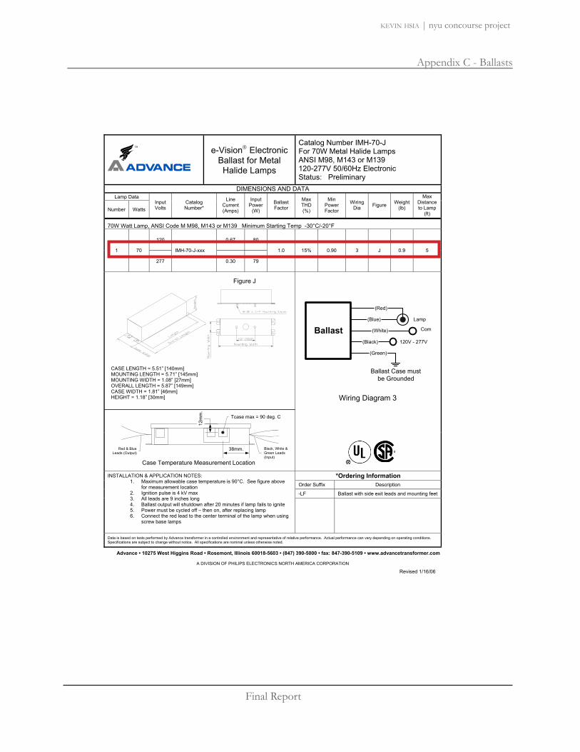

Final Report
Appendix C - Ballasts
kevin hsia | nyu concourse project

Final Report
Appendix C - Ballasts
kevin hsia | nyu concourse project

Final Report
Appendix C - Ballasts
kevin hsia | nyu concourse project
Performance Guide
Ordering Guide
OPTOTRONIC® OTDIM Module
OSRAM SYLVANIA National Customer Support Center1-800-LIGHTBULB (1-800-544-4828)www.sylvania.com
Dimensions: Packaging:6.77" L x 1.65" W x 0.79" H Quantity: 20 pieces/carton(172mm L x 42mm W x 20mm H) Weight: 0.165 lbs ea. (approx.)
3.3 lbs/cartonLead Lengths: Non-leaded
Wiring Requirements: Input, load and control wires: 14AWG solid or stranded Cu only
Item Number 51516 OT DIM
OPTOTRONIC
Dimming Module
OT DIM
System Life / Warranty
OPTOTRONIC OTDIM are warrantedfor 5 years. OPTOTRONIC andQUICKTRONIC Products are coveredby our QUICK 60+ system warranty,a comprehensive light source,ballast and power supply systemwarranty. For additional details,refer to our latest version of theQUICK 60+ warranty bulletin.
Specifications subject to changewithout notice.
Nominal Nominal Max.Input Input Control Output Output
Item Voltage Current Voltage Power CurrentNumber Description (VDC) (A) (VDC) (W) (A)
51516 OTDIM 10.5 5.3 0-10VDC 0-52.5 524 5.3 0-10VDC 0-120 5
Dim module shall be an LEDOPTOTRONIC electronicdimming module with 10 - 24VDC input, with 0 –10 VDCcontrol voltage.
Dim ModuleInput Voltage Range: 9.5-25VDCInput Current: 5.3 Amps max.Output Frequency: 135 HzOutput Current: 5 Amps max.Dimming Range: 0 – 100%Control Voltage: 0 – 10 VDC,
0.6 ma max.Temp. Range: -20°C through
+50°CMax. Case Temperature: 70°CColor Mixing: Yes*
* For compatibility information withcolor mixing protocols/1-10Vdimming controls, contact OSRAMSYLVANIA.
Specifications
20 mm
42 mm
172 ±0.3 mm
3.5 mm
164 ±0.3 mm
10-24VDC
Power supply unit LED Modules
Input
Control signal 1…10VDC
NL
OT DIMOT
1-10VDC<0.6mA
Wiring Diagram:

Final Report
Appendix C - Ballasts
kevin hsia | nyu concourse project
Universal Outdoor Drivers for 12V and 24V LED systems
Applications
Orientation/Step Lighting
Architectural Lighting
Channel Letters
Contour Lighting
Edge Lighting
Features Benefits UL Class 2 Limited output voltage and current plus isolation
for safe operation UL Outdoor Damp location rated - Fully potted for moisture resistance and thermalIP 66 benefits Ultra small, compact size Facilitates new, low-profile fixture design Extreme low temperature Allows use in any outdoor application Performance (-40°C) Generous high temperature Margin flexibility to facilitate fixture design capability (+60°C) Tightly regulated output Consistent light output across line (1% line, 5% load) and load levels 5 year warranty Peace of mind for your new products and for
end users…from the industry’s most trusted component maker
Powered by Advance Advance is preferred by end users – Enhance the value of your product
LEDs have evolved into a practical, flexible light source for a wide varietyof illumination applications. CommonLED products available in the markettoday are configured in a series-parallel array – designed to be powered by a suitable 24vdc driver –which allows flexibility to connect variable load levels. These operatingvoltages have become the standard in the industry.
The Brain Behind the Bright IdeaXitanium LED drivers from Advance are designed specifically for 24V LED systems and incorporate features that enable broad commercialization of end-use solid-state lighting products.

Final Report
Appendix C - Ballasts
kevin hsia | nyu concourse project
Quick Selection Table Catalog Number Description Application
LEDINTA0024V41FO Intellivolt 100 Watt 24Vdc Outdoor 24Vdc LED Systems
LED Driver Specifications Input Output
Description Catalog Number Volts(V)
PowerMax(W)
CurrentMax(A)
PowerMax(W)
VoltageNom(V)
CurrentMax(A)
CaseTemp Max(°C) Figure
Weight(Grams)
120 0.98230 0.51100 Watt LEDINTA0024V41FO 277
117.0.042
100.0 24.0 4.1 90 A 640
Total Harmonic Distortion: 20% max Power Factor: 90% min Line Regulation: 1% output variation across input voltage range Load Regulation: 5% output variation across input voltage range Current Crest Factor: 1.5 max Environmental Protection: IP66 outdoor rated EMI: FCC47 SubPart15, CISPR15 and CISPR22 Class A Protection: Meet UL1310 for Class 2; Inherent short-circuit protection, self-limited; overload protected; 3.2KV output insulation AC Input and DC Output: 2 (0.78mm²) Solid Copper Wires, 15cm long
Dimensions
Fig. A
Advance, A Division of Philips Electronics North America · 10275 W Higgins Road · Rosemont, IL 60018 · USA Tel: + 1 847 390-5205 · Fax: + 1 847 390-5264 · Revised 09/05PJJ

Final Report
Appendix G - Lighting Controls
kevin hsia | nyu concourse project
www.wattstopper.com8 0 0 . 8 7 9 . 8 5 8 5E17
DA
YL
IG
HT
IN
G
CO
NT
RO
LS
LightSaver® LS-101 Daylighting Controller
PROJECT
LOCATION/TYPE
LED StatusIndicator
Select Button
LCD Display
Menu Button
• Easy-to-read LCD Display prompts installerthrough set-up and accurately reflects the currentcontrol mode and light level.
• Four user-adjustable parameters: ON Setpoint,OFF Setpoint, OFF Setpoint Time Delay, and ‘HoldOn While Occupied’ Mode (if wired with an occu-pancy sensor)
• Test Mode overrides the programmed Time Delayto allow installer to check if settings are correct.
• Control load status verification allows testing andconfirmation that the wiring is correct by pressingthe select button
• Manual Override for one hour (if wired with a lowvoltage, push-button wall switch)
The LS-101 Daylighting Controller is a single zone,ON/OFF device which can be installed in an openor closed loop application to turns lights off auto-matically when sufficient natural daylight ispresent. It consists of an advanced digital multi-band photosensor that measures light similar tothe way the human eye perceives it, an on-boardmicrocontroller, and an LCD display. This photo-sensor is positioned behind a 100Þ cone that cutsoff unwanted light, preventing false triggering.
On, Off & Deadband Settings
Applications
The LS-101 Daylighting Controller can be used tocontrol any type of lighting: incandescent, fluores-cent, compact fluorescent (CFL) and HID . Thesensors work in peripheral offices, skylit areas,cafeterias, warehouses and any other indoor areaswith natural light access.
Operation
The LS-101 is a self-contained 24 VDC device withan extended range of 1-1400 fc that only requires alow voltage power pack to operate. By adjustingthe setpoints, it will turn lighting systems off whenthe ambient light levels exceed the OFF setpoint,and will turn lighting systems back on whennatural light levels have fallen far enough towarrant it. Because of its factory presets, manyset-up applications require little or no adjustmentof the settings. The LS-101 is expandable with alow voltage wall switch to enable manual overrideor with a occupancy sensor to enable its ‘Hold OnWhile Occupied’ feature.
DescriptionProductOverview
Features • Meets Section 119’s requirement for daylighting inCalifornia’s Title 24 Lighting Code.
• LED status indicator identifies if the LS-101 is inOverride or Test Mode, or if the device hasswitched the lights on or off.
• Two mounting options for either top-lit or side-litapplications
• Low voltage leads are color coded to match wirecolors on the power pack.
• Shape and design developed to prevent mis-align-ments.
• Can be programmed in most daylight conditions
Removable Cover
Digital Multi-BandPhotosensor
100º Cone
The LS-101 features adjustable settings for ONsetpoint, OFF setpoint and time delay, shouldadjustment be required. Adjusting the ON setpointwill automatically calculate your OFF setpoint to apredetermined deadband setting. The deadbandcan be adjusted to a value of 25%, 50%, 75% or100% above the ON setpoint. When the sensedlight level drops below the ON setpoint for 20seconds, the output signal will switch on. Andwhen the sensed light level exceeds the OFF set-point for the length of the time delay, the outputsignal will switch OFF. The time delay can beadjusted to 3, 10, 20 or 30 minutes.

Final Report
Appendix G - Lighting Controls
kevin hsia | nyu concourse project
DA
YL
IG
HT
IN
G
CO
NT
RO
LS
www.wattstopper.com8 0 0 . 8 7 9 . 8 5 8 5 E18
Wiring &Installation
Location
DeadbandLevel Chart
Pub. No. 24702
OrderingInformation
Specifications • Digital Multi-Band Photosensor Range: 1-1400foot candles
• ON Setpoint Range: 1-850 foot candles• Status Indicator: Multi-function green LED• Power Requirements: 12/24 VDC; 7 mA typical• Output Signal: 24VDC; maximum 120 mA
• Location: Suitable for dry interior locations• Environment: 32 to 120ºF, less than 90% rh • Dimensions: 2.4” diameter x 0.7” deep (61mm
x 17mm)• Five-year warranty• UL listed
Wiring Diagram Mounting Installation
Side Lighting Application Top Lighting Application
Occupancy Input
Common
+24VDC in
RedWhiteNeut.Power Pack
Red
Bla
ck
Blu
eLighting
Load
BlackHot
Red
LS-1
01
Blue
Red
Black
Yellow
WhiteControl Out
+24VDC in
Common
Any 24VDC Occupancy Sensor
Control Out
LVS-1Switch
Optional
Optional
+24VDC in
Ceiling
Retaining Nut
Plastic Washer
Peak
Sensitivity
LS-101
Window
Light Fixture
Typical Daylit Zone, about 12' (3.6m)
100°
LS-101
Light Fixture
Skylight
100°
10
0°
100
90
80
70
60
50
40
30
20
10
0
8am 9am 10am 11am 12pm 1pm 2pm 3pm 4pm 5pm 6pm 7pm 8pm
Time
Foot
cand
le
OFF Setpoint
ON Setpoint
Energy Savings Opportunity
Deadband
Daylight
Electric Light
LS-101 12-24 VDC 7 mA Typical
Catalog No. Voltage Current Photosensor Range Deadband Adjustment Range
1-1400 foot candles 25%, 50%, 75% & 100%above the ON setpoint
If the LS-101’s photosensor lighting level dropsbelow the ON setpoint, the lights will remainon. If the sensor’s lighting level rises above theOFF setpoint, the LS-101 will automaticallyturn the lights off. If the sensor’s lighting levelremains in the predetermined deadband range(25%, 50%, 75% or 100%) the lighting will bepassive until the sensor’s level reaches thehigh or low setpoints.
For other wiring diagrams, please visit the CAD ResourceCenter at www.wattstopper.com

Final Report
Appendix G - Lighting Controls
kevin hsia | nyu concourse project
OC HT
The World’s Finest Multi-Scene Preset Lighting Control NETWORKABLE UNITS WITH ADVANCED FEATURES
Product Family Features• Control every light in the room with
a single touch• Programmable fade times provide
smooth transitions between lighting scenes
• Easy integration with controllable windowtreatments and projection screens
• Offers multi-location control in many elegant wallstation styles
• Integration to other systems though contact closures or RS-232 interfaces
Specification Features• Square law dimming• Lutron’s patented RTISS™ circuitry
maintains constant light levels underchanging power line conditions
• Lightning strike surge protection to 6000V, 3000A
• Positive air-gap off• Power failure memory• Electrostatic discharge protection
System Features• Up to 8 main units
(for a maximum of 48 lighting zones)• Up to 16 wallstations/control interfaces
(for a total of 24 points of control)
Shown:GRAFIK Eye 3000 Series 2-zone control unit with translucent black cover (T) and white base (WH) in a matte finish.
3000 Series
Color Palette (For latest color information, visit www.lutron.com)
Mat
te
BN CLAAU BLASNSpec
ial M
etal
QZ SC
Met
al
SB BB BC QB
Glo
ss
GLAGAL GIVGWHBLWH BE IV BRGR
BRA
MN LS DSST TCBT
Satin
SW BI ES TP
1 Technical Support • 24 Hours/7 Days • 1·800·523·9466 • www.lutron.com

Final Report
Appendix G - Lighting Controls
kevin hsia | nyu concourse project
TYPE A 12 AWG (120/277V)TYPE B Class 2 PELV wires
Wiring Type Key
System Operation
Interfaces convert the dimmed signal to control special load types
Power Boostersincrease zone capacity up to 16A (1920W)
Wallstations providemulti-location control.A variety of styles are available.
Infrared Transmitters*provide control from anywhere in the room
Control units provide preset lighting control with integral dimmers for scene based control
Window treatment controllers provide coordinated control of natural light with artificial light
Control interfacesconnect lighting controlsto other devices to coordinate performance
En
tire-R
oo
m C
on
trols
2To Order/Customer Service • 8am–8pm ET (US/CAN) • 1·888·LUTRON1
Sources Controlled Directly:
Incandescent Fluorescent
Magnetic Low Voltage
Neon/Cold Cathode All popular sources
Sources Requiring an Interface:
Electronic Low Voltage 3-Wire Fluorescent
0-10V Fluorescent
Tu-Wire® fluorescent dimming ballasts only
non-dim
* Requires line of sight to the control unit

Final Report
Appendix G - Lighting Controls
kevin hsia | nyu concourse project
3100 3500Manual Set-up Yes Yes
PC Set-up Yes
Archive System Configuration
Yes
Copy System Configuration Yes
2-Zone (Cover Open, Actual Size)
Green LEDs indicatelight level
Zone raise/lower buttons set light levels
Scene buttons
Translucent blackor opaque cover
Master raise/lowertemporarily overridesscene settings
Infrared receiver permits control viainfrared remote control, pg.31
Green status lightsindicate“scene on”
Opaque white base
Set fade rate from 0 to 59 seconds,1 to 60 minutes
Off
Available worldwide
3 Technical Support • 24 Hours/7 Days • 1·800·523·9466 • www.lutron.com
GRAFIK Eye® Special Product Features
3100/3500 Series Whole-Home RF Control System
Liaison™ Software
Windows®-based programming utility for 3500 systems and timeclocks
RadioRA®
InterfaceGRAFIK RA™

Final Report
Appendix G - Lighting Controls
kevin hsia | nyu concourse project
En
tire-R
oo
m C
on
trols
Color PaletteAdd color suffix to model #Examples:Translucent Cover, Opaque Base:GRX-3102- -Opaque Cover, Opaque Base:GRX-3102- -
Cover OptionsOpaque
(Cover and base will match)Translucent Black
(Black cover, choice of base color)
Base ColorsMatte Finishes ships 48 hrs.Matte Cover Options: or
Gloss Finishes ships 4-6 wks.Gloss Cover Option: only
Metal Finishes ships 4-6 wks.Metal Cover Option: only
Satin Finishes ships 4-6 wks.Satin Cover Options: orSee pg.1 for complete color offering and suffixes.
Wallplate DepthDepth listed with each productincludes wallplate and backbox.Wallplate depth is 0.35" (9mm).
TA
T
A
TA
T
A
WHA
WHT
For More Information:www.lutron.com/grafikeyeFax-on-Demand 1·800·523·9466
Controls are 120V, 60Hz unless noted.
Description Maximum Capacity Model # Important Information
Electronic Low Voltage
Electronic low-voltage sources require interfaces.
Fluorescent
Lutron Hi-lume® line-voltage control electronic dimming ballasts require interfaces.
Control UnitsIncandescent, Magnetic Low Voltage,Neon/Cold Cathode, Fluorescent with Tu-Wire® Dimming Ballast
2-Zone Control Units*3100 1200W/VA GRX-3102- -3500 1200W/VA GRX-3502- -Dimensions: W: 5.56”(141mm); H: 4.56”(116mm); D: 2.25”(57mm),depth includes wallplate and backbox. Wallbox size: two-gang,3.50”(89mm) deep.
3-Zone Control Units*3100 1500W/VA GRX-3103- -3500 1500W/VA GRX-3503- -Dimensions: W: 7.25”(184mm); H: 4.56”(116mm); D: 2.25”(57mm),depth includes wallplate and backbox. Wallbox size: three-gang,3.50”(89mm) deep.
4-Zone Control Units*3100 2000W/VA GRX-3104- -3500 2000W/VA GRX-3504- -Dimensions: W: 8.94”(227mm); H: 4.56”(116mm); D: 2.25”(57mm),depth includes wallplate and backbox. Wallbox size: four-gang,3.50” (89mm) deep.
6-Zone Control Units*3100 2000W/VA GRX-3106- -3500 2000W/VA GRX-3506- -Dimensions: W: 8.94”(227mm); H: 4.56”(116mm); D: 2.25”(57mm),depth includes wallplate and backbox. Wallbox size: four-gang,3.50” (89mm) deep.
* Products Above: Single zone capacity is 800W/6.67A per zone.Combined total of all zones should not exceed maximum capacity.
4To Order/Customer Service • 8am–8pm ET (US/CAN) • 1·888·LUTRON1
GRAFIK Eye® 3000 Series

Final Report
Appendix G - Lighting Controls
kevin hsia | nyu concourse project
Shown actual size:Architectural style wallstation in white (WH).
2.75” (70mm)
4.56
”(1
16m
m)
.30”(7.6mm)
Product Family Features• Sleek slim-button wallstations to fit a
designer style opening for use in singleor multigang applications
• For use with one or more GRAFIK Eye3000 Series control units; provides additional control points throughout a space
• Controls are available with infraredreceiver for control by infrared remotecontrol, pg.31
• Access all 16 preset scenes stored inone or more GRAFIK Eye control units
• Master control wallstation permits control of an entire GRAFIK Eye 3000system from one location
Layout and Installation• Wire with low-voltage cable, pg.28• Power up to three wallstations/control
interfaces from a single 3000 seriescontrol unit; for more than three, use aGRX-12VDC
• Derating not required when ganged• Each designer style wallstation counts
one toward system maximum 16 wallstations/control interfaces
9 Technical Support • 24 Hours/7 Days • 1·800·523·9466 • www.lutron.com
Architectural Style Wallstations3000 Series
Color Palette (For latest color information, visit www.lutron.com)
Mat
te
BN CLAAU BLA
* To order contact Lutron Customer Service
SNSpec
ial M
etal*
QZ SC
Met
al*
SB BB BC QB
BLGR BRWH BE IV LAAL
BRA

Final Report
Appendix G - Lighting Controls
kevin hsia | nyu concourse project
Controls are Class2/PELV unless noted.
Global Ordering
En
tire-R
oo
m C
on
trols
Ships in 48 hrs.
Color PaletteMatte FinishAdd color suffix to model #Example: SG-4SN-
WhiteBeigeIvoryGrayBrownBlack
Satin Finish (Insert models only)Add color suffix to model #Example: SG-4SI-
SnowBiscuitEggshellTaupeMidnightBlue MistLimestoneStoneDesert StoneTerracottaOchreHot
Gloss Finish (Insert models only)Add color suffix to model #Example: SG-4SI-
WhiteLight Almond
Colors meet NEMA color standards where standards exist
*Insert ModelsUse insert models with multigang wallplates.
GLAGWH
GWH
HTOCTCDSSTLSBTMNTPESBISW
SW
BLBRGRIVBEWH
WH
For More Information:www.lutron.com/grafikeyeFax-on-Demand 1·800·523·9466
Description Model # Important Information
8To Order/Customer Service • 8am–8pm ET (US/CAN) • 1·888·LUTRON1
GRAFIK Eye® 3000 Series
4-Scene Wallstation with Off, Raise/Lower, and IR Receiver
4-Scenes, Off, Raise/Lower, SG-4SIRN-Infrared Receiver with Backlit Buttons SG-4SIRI- *• Recalls preset light levels for four scenes (1-4, 5-8, 9-12
or 13-16; selected in the field) plus off• Wireless infrared remote controls can recall scenes
(determined by wallstation field settings), plus off and master raise/lower, pg.31
• Fine-tuning of light levels with master raise/lower buttons
seeTouch Style Wallstations4-Scene Wallstation with Off and Raise/Lower
4-Scenes with Off, Raise/Lower SG-4SN-and Backlit Buttons SG-4SI- *• Recalls preset light levels for four scenes (1-4, 5-8, 9-12,
or 13-16; selected in the field) plus off• Fine-tuning of light levels with master raise/lower buttons
4-Partition Status Wallstation
Partition Control with Backlit Buttons SG-4PSN-SG-4PSI- *
• Provides four buttons to determine which GRAFIK Eye controlunit(s) operate independently or in combination to reflect partition status for up to four moveable walls (five rooms)
• Last button resets all control units to independent operation
4-Button Master Control Wallstation
Master Control with Backlit Buttons SG-4MN-SG-4MI- *
• Each of four buttons toggles individually selected GRAFIK Eye control unit(s) between Scene 1 and off
• Last button turns selected GRAFIK Eye control unit(s) off (can be changed in the field to turn control unit(s) on)
Products Above: Single-gang wallplate included with product.For replacement, metal, and multigang wallplates, contact Lutron Customer Service.Dimensions: W: 2.75”(70mm); H: 4.56”(116mm); D: 1.69”(43mm),depth includes wallplate and backbox. Wallplate depth is0.30”(7.6mm). Wallbox size: single gang

Final Report
Appendix E - Backup Generator
kevin hsia | nyu concourse project
2008 Cummins Power Generation Inc. All rights reserved Specifications subject to change without notice Cummins Power Generation and Cummins are registered trademarks of Cummins Inc. PowerCommand, AmpSentry InPower and “Our energy working for you.” are trademarks of Cummins Power Generation. Other company, product or service names may be trademarks or service marks of others. S-1580a (5/08)
Diesel generator set 4BT3.3 series engine EPA emissions
Description Cummins Power Generation commercial generator sets are fully integrated power generation systems providing optimum performance, reliability and versatility for stationary standby and prime power applications.
This generator set is designed in facilities certified to ISO 9001 and manufactured in facilities certified to ISO 9001 or ISO 9002.
The Prototype Test Support (PTS) program verifies the performance integrity of the generator set design. Cummins Power Generation products bearing the PTS symbol meet the prototype test requirements of NFPA 110 for Level 1 systems.
All low voltage models are CSA certified to product class 4215-01.
The generator set is available Listed to UL 2200, Stationary Engine Generator Assemblies.
U.S. EPA Engine certified to U.S. EPA Nonroad Source Emissions Standards, 40 CFR 89, Tier 2.
Features
Cummins® heavy-duty engine - Rugged 4-cycle, industrial diesel delivers reliable power, low emissions and fast response to load changes.
Alternator - Several alternator sizes offer selectable motor starting capability with low reactance 2/3 pitch windings, low waveform distortion with non-linear loads and fault clearing short-circuit capability.
Control system - The PowerCommand® 1301 electronic control is standard equipment and provides total genset system integration including automatic remote starting/stopping, precise frequency and voltage regulation, alarm and status message display, output metering, auto-shutdown at fault detection and NFPA 110 Level 1 compliance. The optional PowerCommand 2100 control is UL 508 Listed and provides AmpSentry™ protection.
Cooling system - Standard integral set-mounted radiator system, designed and tested for rated ambient temperatures, simplifies facility design requirements for rejected heat.
Enclosures - Optional weather protective and sound attenuated enclosures are available.
Fuel tanks - Dual wall sub-base fuel tanks and in-skid day tanks are also offered.
NFPA - The genset accepts full rated load in a single step in accordance with NFPA 110 for Level 1 systems.
Warranty and service - Backed by a comprehensive warranty and worldwide distributor network.
Standby rating Prime rating Continuous rating Data sheets
Model 60 Hz kW (kVA)
50 Hz kW (kVA)
60 Hz kW (kVA)
50 Hz kW (kVA)
60 Hz kW (kVA)
50 Hz kW (kVA) 60 Hz 50 Hz
DGGD 35 (44) 30 (38) D-3438
DGHD 40 (50) 36 (45) D-3439
DGHE 50 (63) 45 (56) D-3440
35 kW - 50 kW standby

Final Report
Appendix E - Backup Generator
kevin hsia | nyu concourse project
Our energy working for you.™
www.cumminspower.com
2008 Cummins Power Generation Inc. All rights reserved Specifications subject to change without notice Cummins Power Generation and Cummins are registered trademarks of Cummins Inc. PowerCommand, AmpSentry, InPower and “Our energy working for you.” are trademarks of Cummins Power Generation. Other company, product or service names may be trademarks or service marks of others. S-1580a (5/08)
Generator set specifications Governor regulation class ISO 8528 Part 1 Class G3 Voltage regulation, no load to full load ± 1.0% Random voltage variation ± 1.0% Frequency regulation 5%. Random frequency variation ± 0.5% (isochronous optional 0.25%) Radio frequency emissions compliance Meets requirements of most industrial and commercial applications
Engine specifications Design Turbocharged Bore 95.0 mm (3.74 in) Stroke 115.1 mm (4.53 in) Displacement 3.3 L (199.0 in3) Cylinder block Cast iron, in-line, 4 cylinder Battery capacity 550 amps minimum at ambient temperature of 0 °C (32 °F) Battery charging alternator 35 amps Starting voltage 12 volt, negative ground Fuel system Direct injection: number 2 diesel fuel
Fuel filter Single element, 10 micron filtration, spin-on fuel filter with water separator
Air cleaner type Dry replaceable element Lube oil filter type(s) One spin-on, full flow filter Standard cooling system 40 °C (104 °F) ambient radiator
Alternator specifications Design Brushless, 4 pole, drip proof revolving field Stator 2/3 pitch Rotor Direct coupled, flexible disc Insulation system Class H per NEMA MG1-1.65 Standard temperature rise 150 °C (302 °F) standby Exciter type Shunt Phase rotation A (U), B (V), C (W) Alternator cooling Direct drive centrifugal blower AC waveform total harmonic distortion < 5% no load to full linear load, < 3% for any single harmonic Telephone influence factor (TIF) < 50 per NEMA MG1-22.43 Telephone harmonic factor (THF) < 3
Available voltages Three phase reconnectable
Single phase non-reconnectable
Three phase non-reconnectable
120/208 240/416
120/240 254/440
127/220 277/480
139/240 120/240 220/380 347/600
Note: Consult factory for other voltages.
Generator set options and accessories Engine
120/240 V, 1000 W coolant heater 120/240 V, 150 W lube oil heater Electronic governor
Fuel system 12 hour dual wall sub-base tank 24 hour dual wall sub-base tank
Single wall sub-base tank, 80 gal (303 L)
Alternator 105 C (221 °F) rise alternator 125 C (257 °F) rise alternator 120/240 V, 100 W anti-condensation heater Extended stack (full single phase output) PMG excitation Single phase
Exhaust system Genset mounted muffler Heavy duty exhaust elbow Slip on exhaust connection
Cooling system 50 C (122 F) ambient cooling
Generator set AC entrance box Batteries
Battery charger Enclosure: aluminum, steel, weather protective or sound attenuated Export box packaging UL 2200 Listed Main line circuit breaker Spring isolators 2 year standby warranty 2 year prime power warranty 5 year basic power warranty
Note: Some options may not be available on all models - consult factory for availability.

Final Report
Appendix E - Backup Generator
kevin hsia | nyu concourse project
2008 Cummins Power Generation Inc. All rights reserved Specifications subject to change without notice Cummins Power Generation and Cummins are registered trademarks of Cummins Inc. PowerCommand and “Our energy working for you.” are trademarks of Cummins Power Generation. S-1464m (4/08)
Transfer switch OTEC open or delayed transition
Description OTEC transfer switches are designed for operation and switching of electrical loads between primary power and standby generator sets. They are suitable for use in emergency, legally required, and optional standby applications. The switches monitor both power sources, signal generator set startup, automatically transfer power, and return the load to the primary power source once a stable utility is available.
All switches are UL 1008 Listed with UL Type Rated cabinets and UL Listed CU-AL terminals.
All switches are certified to CSA 282 Emergency Electrical Power Supply for Buildings, up to 600 VAC.
NEC Equipment shall be suitable for use in systems compliant to 700, 701 and 702.
All switches comply with NFPA 70, 99 and 110.
All switches comply with NEMA ICS 10.
All switches comply with IEEE 446 Recommended Practice for Emergency and Standby Power Systems.
This transfer switch is designed and manufactured in facilities certified to ISO9001.
Features
PowerCommand® control - A standard, fully featured microprocessor-based control. Software-enabled features, settings, and adjustments are available for ease of setup and accuracy.
Advanced transfer switch mechanism - Unique bi-directional linear actuator provides virtually friction-free, constant force, straight-line transfer switch action during automatic operation.
Manual operation - Manual operating handles, shielded termination, and over-center type contact mechanisms allow effective, manual operation, under de-energized conditions.
Positive interlocking - Mechanical and electrical interlocking prevent source-to-source connection through the power or control wiring.
Main contacts - Heavy-duty silver alloy contacts with separate arcing surfaces and multi-leaf arc chutes are rated for total system transfer including overload interruption.
Easy service/access - Plug connections, door-mounted controls, ample access space, and compatible terminal markings. The control is field programmable.
Product lines, accessories and services - Cummins Power Generation offers a wide range of accessories and services to suit your requirements.
Warranty and service - Backed by a comprehensive warranty and worldwide distributor network.
40 - 1000 Amp

Final Report
Appendix E - Backup Generator
kevin hsia | nyu concourse project
Our energy working for you.™
www.cumminspower.com
2008 Cummins Power Generation Inc. All rights reserved Specifications subject to change without notice Cummins Power Generation and Cummins are registered trademarks of Cummins Inc. PowerCommand and “Our energy working for you.” are trademarks of Cummins Power Generation. S-1464m (4/08)
Transfer switch mechanism
A bi-directional linear motor actuator powers OTEC Transfer Switches. This design provides virtually friction-free, constant force, straight-line transfer switch action with no complex gears or linkages.
Independent break-before-make action is used for both 3-pole and 4-pole/switched neutral switches. On 3-pole/switched neutral switches, this action also prevents the objectionable ground currents and nuisance ground fault tripping that can result from overlapping designs.
A mechanical interlock prevents simultaneous closing of normal and emergency contacts.
Electrical interlocks prevent simultaneous closing signals to normal and emergency contacts and interconnection of normal and emergency sources through the control wiring.
Long-life, high pressure, silver alloy contacts resist burning and pitting. Separate arcing surfaces further protect the main contacts. Contacts are mechanically held in both normal and emergency positions for reliable, quiet operation.
Superior arc interruption is accomplished through multiple leaf arc chutes that cool and quench the arcs. Barriers separate the phases and prevent inter-phase flashover
Specifications
Voltage rating Transfer switches rated from 40 A through 1000 A are rated up to 600 VAC, 50 or 60 Hz.
Arc interruption Multiple leaf arc chutes cool and quench the arcs. Barriers prevent interphase flashover.
Neutral bar A full current-rated neutral bar with lugs is standard on enclosed 3-pole transfer switches.
Auxiliary contacts Two contacts (one for each source) are provided for customer use. Wired to terminal block for easy access. Rated at 10A continuous and 250 VAC maximum.
Operating temperature -22 oF (-30 oC) to 140 oF (60 oC)
Storage temperature -40 F (-40 C) to 140 F (60 C)
Humidity Up to 95% relative, non-condensing
Altitude Up to 10,000 ft (3,000 m) without derating Total transfer time (source-to-source)
Will not exceed 6 cycles at 60 Hz with normal voltage applied to the actuator and without delayed transition enabled.
Manual operation handles Transfer switches are equipped with permanently attached operating handles and quick-break, quick-make contact mechanisms suitable for manual operation under de-energized conditions.
Open transition - The OTEC automatic transfer switch, equipped with In-phase monitor, determines when to transfer the load from one source to another. The switch contacts operate in a break-before-make sequence. The Open Transfer OTEC is field-configurable for delayed transition below 1000 amps.
Delayed (programmed) transition - The OTEC is also available as a programmed (delayed) transition transfer switch. The delayed transition OTEC completely disconnects the load from both sources for an adjustable period of time to allow regenerative voltage to decay to a safe level prior to connecting to the new source. By allowing motor fields to decay, nuisance tripping breakers and load damage are prevented. Delayed transition transfer is recommended by NEMA MG-1.

Final Report
Appendix E - Backup Generator
kevin hsia | nyu concourse project
Our energy working for you.™
www.cumminspower.com
2008 Cummins Power Generation Inc. All rights reserved Specifications subject to change without notice Cummins Power Generation and Cummins are registered trademarks of Cummins Inc. PowerCommand and “Our energy working for you.” are trademarks of Cummins Power Generation. S-1464m (4/08)
PowerCommand® microprocessor control
Simple, easy-to-use control provides transfer switch information and operator controls
LED lamps for source availability and source connected indication, exercise mode, and test mode. LED status lamps also provided for control set-up and configuration.
Control pushbuttons to initiate test, override time delays, and set exercise time.
Field-configurable for in-phase or delayed (programmed) transition.
Integral exerciser clock
Control is prototype-tested to withstand voltage surges per EN 60947-6-1.
Gold-flashed generator start contacts
Control functions
Voltage sensing: All phases on the normal source and single phase on generator source. Normal Source Pickup: adjustable 90-95%, Dropout: adjustable 70-90% of nominal voltage; Generator Source Pickup: 90%, dropout: 75% of nominal voltage. Frequency sensing: Generator Source Pickup: 90% of nominal frequency; Dropout: 75% of nominal frequency. Operating modes: Open transition with programmed transition (adjustable 0-10 seconds); Open transition with in-phase monitor and delayed transition backup; Exercise mode; and Test mode. In-phase: Configurable for initiation of transfer functions when sources are in phase, and including ability to enable a programmed transition backup to the function so that if sources are not in-phase within 120 seconds the system will retransfer with programmed transition function. Exerciser clock: Switch is furnished with an integral engine exerciser configurable for operation on a 7, 14, 21, or 28-day cycle with a fixed exercise period duration of 20 minutes. A 12-hr exerciser time offset allows for the convenient setting of exercise time without the need to activate the timer at the exact time that you need to schedule the generator exercise for. Software selectable capability allows for the exercising of the generator with or without load.
Time-delay functions
Engine start: Prevents nuisance genset starts due to momentary power system variation or loss. Adjustable: 0-10 seconds; default: 3 seconds. Transfer normal to emergency: Allows genset to stabilize before application of load. Prevents power interruption if normal source variation or loss is momentary. Allows staggered transfer of loads in multiple transfer switch systems. Adjustable 0-300 seconds, default 5 seconds. Retransfer emergency to normal: Allows the utility to stabilize before retransfer of load. Prevents needless power interruption if return of normal source is momentary. Allows staggered transfer of loads in multiple transfer switch systems. Adjustable 0-30 minutes, default 10 minutes. Genset stop: Maintains availability of the genset for immediate reconnection in the event that the normal source fails shortly after transfer. Allows gradual genset cool down by running unloaded. Adjustable 0-30 minutes, default 10 minutes. Delayed (programmed) transition: Controls the speed of operation of the transfer switch power contacts to allow load generated voltages from inductive devices to decay prior to connecting a live source. Adjustable 0-10 seconds, default 0 seconds. Elevator signal: Provides a relay output contact for the elevator signal relay (load disconnect). The signal can also be configured to provide a post transfer delay of the same duration. Adjustable: 0-300 seconds (requires optional elevator signal relay for use).
Options
Elevator signal relay: Provides a relay output contact for the signal relay function Programmable exerciser clock: Provides a fully-programmable 7-day clock to provide greater flexibility in scheduling exercise periods than standard integral exerciser. Peaking function feature allows for generator operation during periods of high utility rates.
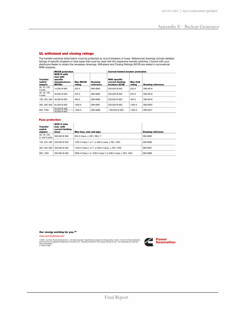
Final Report
Appendix E - Backup Generator
kevin hsia | nyu concourse project
Our energy working for you.™
www.cumminspower.com
2008 Cummins Power Generation Inc. All rights reserved Specifications subject to change without notice Cummins Power Generation and Cummins are registered trademarks of Cummins Inc. PowerCommand and “Our energy working for you.” are trademarks of Cummins Power Generation. S-1464m (4/08)
UL withstand and closing ratings The transfer switches listed below must be protected by circuit breakers or fuses. Referenced drawings include detailed listings of specific breakers or fuse types that must be used with the respective transfer switches. Consult with your distributor/dealer to obtain the necessary drawings. Withstand and Closing Ratings (WCR) are stated in symmetrical RMS amperes.
MCCB protection Current limited breaker protection
Transfer switch ampere
WCR @ volts max with specific manufacturers MCCBs
Max MCCB rating
Drawing reference
With specific current limiting breakers (CLB)
Max CLB rating Drawing reference
40, 70, 125 3-pole 14,000 @ 600 225 A 098-6885 200,000 @ 600 225 A 098-6918
40, 70, 125 4-pole
30,000 @ 600 225 A 098-6885 200,000 @ 600 225 A 098-6918
150, 225, 260 30,000 @ 600 400 A 098-6886 200,000 @ 600 400 A 098-6919
300, 400, 600 65,000 @ 600 1200 A 098-6887 200,000 @ 600 1200 A 098-6920
65,000 @ 480 800, 1000
50,000 @ 600 1400 A 098-6888 200,000 @ 600 1400 A 098-6921
Fuse protection
Transfer switch ampere
WCR @ volts max. with current limiting fuses Max fuse, size and type Drawing reference
40, 70, 125 3- and 4-pole 200,000 @ 600 200 A Class, J, RK1, RK5, T 098-6885
150, 225, 260 200,000 @ 600 1200 A Class L or T, or 600 A class J, RK1, RK5 098-6886
300, 400, 600 200,000 @ 600 1200 A Class L or T, or 600 A Class, J, RK1, RK5 098-6887
800, 1000 200,000 @ 600 2000 A Class L or 1200 A class T or 600 A class J, RK1, RK5 098-6888

Final Report
Appendix E - Backup Generator
kevin hsia | nyu concourse project
2008 Cummins Power Generation Inc. All rights reserved Specifications subject to change without notice Cummins Power Generation and Cummins are registered trademarks of Cummins Inc. “Our energy working for you.” is a trademark of Cummins Power Generation. D-3439 (4/08)
Model: DGHD Frequency: 60 Fuel type: Diesel KW rating: 40 standby 36 prime Emissions level: EPA Nonroad Tier 2
Exhaust emission data sheet: EDS-1079 EPA Tier 1 exhaust emission compliance sheet: EPA-1113 Sound performance data sheet: MSP-192 Cooling performance data sheet: MCP-116 Prototype test summary data sheet: PTS-151 Standard set-mounted radiator cooling outline: 0500-3426 Optional set-mounted radiator cooling outline: Optional heat exchanger cooling outline: Optional remote radiator cooling outline:
Standby Prime Continuous Fuel consumption kW (kVA) kW (kVA) kW (kVA) Ratings 40 (50) 36 (45) Load 1/4 1/2 3/4 Full 1/4 1/2 3/4 Full Full US gph 0.96 1.68 2.4 3.3 0.92 1.5 2.2 2.9 L/hr 4 6 9 13 3 6 8 11
Engine Standby rating
Prime rating
Continuous rating
Engine manufacturer Cummins Inc.
Engine model 4BT3.3-G6, NR2
Configuration Cast iron, in-line 4 cylinder
Aspiration Turbocharged Gross engine power output, kWm (bhp) 61 (82.0) 53 (72.0) BMEP at rated load, kPa (psi) 1250 (181)
Bore, mm (in) 95.0 (3.74)
Stroke, mm (in) 115.1 (4.53)
Rated speed, rpm 1800
Piston speed, m/s (ft/min) 6.9 (1359.0)
Compression ratio 18:1
Lube oil capacity, L (qt) 7.9 (8.4)
Overspeed limit, rpm 2100 ± 50
Regenerative power, kW 8.50
Fuel flow Fuel flow at rated load, L/hr (US gph) 39.8 (10.5)
Maximum inlet restriction, mm Hg (in Hg) 73.7 (2.9)
Maximum return restriction, mm Hg (in Hg) 381.0 (15.0)
Generator set data sheet

Final Report
Appendix E - Backup Generator
kevin hsia | nyu concourse project
Our energy working for you.™
www.cumminspower.com
2008 Cummins Power Generation Inc. All rights reserved Specifications subject to change without notice Cummins Power Generation and Cummins are registered trademarks of Cummins Inc. “Our energy working for you.” is a trademark of Cummins Power Generation. D-3439 (4/08)
Air Standby rating
Prime rating
Continuous rating
Combustion air, m3/min (scfm) 4.0 (142) 3.7 (131)
Maximum air cleaner restriction w/clean filter, kPa (in H2O) 3.0 (12.0)
Alternator cooling air, m3/min (scfm) 18.0 (635.0)
Exhaust
Exhaust flow at rated load, m3/min (cfm) 12.9 (456) 11.8 (417)
Exhaust temperature, °C (°F) 590 (1094) 551 (1024)
Maximum back pressure, kPa (in H2O) 10.2 (41.0)
Standard set-mounted radiator cooling Ambient design, °C (°F) 54 (129) 55 (131)
Fan load, kW (HP) 1.3 (1.7)
Coolant capacity (with radiator), L (US gal) 15.1 (4.0)
Cooling system air flow, m3/min (scfm) 85 (3000)
Total heat rejection, MJ/min (Btu/min) 2.3 (2177)
Maximum cooling air flow static restriction, kPa (in H2O) 0.12 (0.5)
Optional set-mounted radiator cooling Ambient design, °C (°F)
Fan load, kWm (HP)
Coolant capacity (with radiator), L (US gal)
Cooling system air flow, m3/min (scfm)
Total heat rejection, MJ/min (Btu/min)
Maximum cooling air flow static restriction, kPa (in H2O)
Optional heat exchanger cooling Set coolant capacity, L (US gal) Heat rejected, jacket water circuit, MJ/min (Btu/min) Heat rejected, after-cooler circuit, MJ/min (Btu/min) Heat rejected, fuel circuit, MJ/min (Btu/min) Total heat radiated to room, MJ/min (Btu/min) Maximum raw water pressure, jacket water circuit, kPa (psi)
Maximum raw water pressure, aftercooler circuit, kPa (psi)
Maximum raw water pressure, fuel circuit, kPa (psi)
Maximum raw water flow, jacket water circuit, L/min (US gal/min)
Maximum raw water flow, aftercooler circuit, L/min (US gal/min)
Maximum raw water flow, fuel circuit, L/min (US gal/min)
Minimum raw water flow @ 27 °C (80 °F) Inlet temp, jacket water circuit, L/min (US gal/min)
Minimum raw water flow @ 27 °C (80 °F) Inlet remp, after-cooler circuit, L/min (US gal/min)
Minimum raw water flow @ 27 °C (80 °F) Inlet temp, fuel circuit, L/min (US gal/min)
Raw water delta P @ min flow, jacket water circuit, kPa (psi)
Raw water delta P @ min flow, after-cooler circuit, kPa (psi)
Raw water delta P @ min flow, fuel circuit, kPa (psi) Maximum jacket water outlet temp, °C (°F) Maximum after-cooler inlet temp, °C (°F) Maximum after-cooler inlet temp @ 25 °C (77 °F) ambient, °C (°F)

Final Report
Appendix E - Backup Generator
kevin hsia | nyu concourse project
Our energy working for you.™
www.cumminspower.com
2008 Cummins Power Generation Inc. All rights reserved Specifications subject to change without notice Cummins Power Generation and Cummins are registered trademarks of Cummins Inc. “Our energy working for you.” is a trademark of Cummins Power Generation. D-3439 (4/08)
Optional remote radiator cooling1
Set coolant capacity, L (US gal) Max flow rate @ max friction head, jacket water circuit, L/min (US gal/min) Heat rejected, jacket water circuit, MJ/min (Btu/min) Total heat radiated to room, MJ/min (Btu/min) Maximum friction head, jacket water circuit, kPa (psi) Maximum static head, jacket water circuit, m (ft) Maximum jacket water outlet temp, C ( F)
Weights2
Unit dry weight kgs (lbs)
Unit wet weight kgs (lbs) 711 (1568)
Notes: 1 For non-standard remote installations contact your local Cummins Power Generation representative. 2 Weights represent a set with standard features. See outline drawing for weights of other configurations.
Derating factors
Standby Engine power available up to 3574 m (11,724 ft). Derate at 0.9% per 100 m (328 ft), above 3574 m (11,724 ft).
Prime Engine power available up to 3574 m (11,724 ft). Derate at 0.9% per 100 m (328 ft), above 3574 m (11,724 ft).
Continuous
Ratings definitionsEmergency standby power (ESP):
Limited-time running power (LTP):
Prime power (PRP):
Base load (continuous) power (COP):
Applicable for supplying power to varying electrical load for the duration of power interruption of a reliable utility source. Emergency Standby Power (ESP) is in accordance with ISO 8528. Fuel Stop power in accordance with ISO 3046, AS 2789, DIN 6271 and BS 5514.
Applicable for supplying power to a constant electrical load for limited hours. Limited Time Running Power (LTP) is in accordance with ISO 8528.
Applicable for supplying power to varying electrical load for unlimited hours. Prime Power (PRP) is in accordance with ISO 8528. Ten percent overload capability is available in accordance with ISO 3046, AS 2789, DIN 6271 and BS 5514.
Applicable for supplying power continuously to a constant electrical load for unlimited hours. Continuous Power (COP) is in accordance with ISO 8528, ISO 3046, AS 2789, DIN 6271 and BS 5514.

Final Report
Appendix E - Backup Generator
kevin hsia | nyu concourse project
Our energy working for you.™
www.cumminspower.com
2008 Cummins Power Generation Inc. All rights reserved Specifications subject to change without notice Cummins Power Generation and Cummins are registered trademarks of Cummins Inc. “Our energy working for you.” is a trademark of Cummins Power Generation. D-3439 (4/08)
Alternator data Three phase table1 105 °C 105 °C 105 °C 105 °C 125 °C 125 °C 125 °C 125 °C 150 °C 150 °C 150 °C
Feature code B418 B415 B268 B304 B417 B414 B267 B303 B416 B413 B419
Alternator data sheet number
202 202 204 202 201 201 203 201 201 201 201
Voltage ranges
110/190 thru 120/208 220/380 thru 240/416
120/208 thru 139/240 240/416 thru 277/480
120/208 thru 139/240 240/416 thru 277/480
347/600
110/190 thru 120/208 220/380 thru 240/416
120/208 thru 139/240 240/416 thru 277/480
120/208 thru 139/240 240/416 thru 277/480
347/600
110/190 thru 120/208 220/380 thru 240/416
120/208 thru 139/240 240/416 thru 277/480
347/600
Surge kW 53.1 52.8 54.4 53.4 52 51.7 53.5 52.5 52 51.7 52.5
Motor starting kVA (at 90% sustained voltage)
Shunt 163 163 231 163 131 131 188 131 131 131 131
PMG 191 191 272 191 155 155 221 155 155 155 155
Full load current amps at standby rating
120/208 139
127/220 131
139/240 120
220/380 76
240/416 60
277/480 60
347/600 48
Single phase table 105 °C 105 °C 105 °C 105 °C 125 °C 125 °C 125 °C 125 °C
Feature code B418 B415 B274 B268 B417 B414 B273 B267 Alternator data sheet number
202 202 203 204 201 201 202 203
Voltage ranges 120/2402 120/2402 120/2403 120/2403 120/2402 120/2402 120/2403 120/2403
Surge kW 50.1 50.1 53 52.8 49.5 49.5 52.2 51.4 Motor starting kVA (at 90% sustained voltage)
Shunt 95 95 113 130 72 72 95 113
PMG 112 112 133 153 85 85 112 133
Full load current amps at standby rating
120/2402 111
120/2403 167
Notes: 1. Single phase power can be taken from a three phase generator set at up to 2/3 set rated 3-phase kW at 1.0 power factor. Also see Note 3 below. 2. The broad range alternators can supply single phase output up to 2/3 set rated 3-phase kW at 1.0 power factor. 3. The extended stack (full single phase output) and 4 lead alternators can supply single phase output up to full set rated 3-phase kW at 1.0 power factor.
Formulas for calculating full load currents:
Three phase output Single phase output
Cummins Power Generation 1400 73rd Avenue N.E. Minneapolis, MN 55432 USA Phone: 763 574 5000 Fax: 763 574 5298
Warning: Back feed to a utility system can cause electrocution and/or property damage. Do not connect to any building’s electrical system except through an approved device or after building main switch is open.
Voltage1000 x eFactorSinglePhas x kW
0.8 x 1.73 x Voltage1000 x kW

Final Report
Appendix E - Backup Generator
kevin hsia | nyu concourse project
2007 Cummins Power Generation Inc. All rights reserved Specifications subject to change without notice Cummins Power Generation and Cummins are registered trademarks of Cummins Inc. “Our energy working for you.” and Quiet Site are trademarks of Cummins Power Generation. AC-171a (707) Page 1 of 4
Enclosures and tanks 230-500 kW
Enclosure features Options
14-gauge steel construction (panels)
12-gauge steel construction (posts)
Stainless steel hardware
Double E-coat green paint
Package Listed to UL 2200
Designed to satisfy all requirements of National Electrical Code installations
Fuel and electrical stub-up area within enclosure perimeter
Fixed louvers
Cambered roof prevents water accumulation
Three recessed, lockable doors per side
Retainers hold doors open for easy access
Enclosed exhaust silencer ensures safety and protects against rust
Rain collar and rain cap
Exterior oil and coolant drains with interior valves for ease of service
Rodent barriers on inlet and outlet
Non-hydroscopic sound attenuating material
Side mounted controls and circuit breakers
Easy access lifting points for spreader bars
Dual vibration isolation system
Enclosure mounts to fuel tank or lifting base
Factory pre-assembled package
Enclosures are designed for outdoor use only
Three levels of sound attenuation
Motorized louvers
Enclosed motorized louvers to protect from ice and snow accumulation (available on air inlet for all models and on air outlet on Level II enclosures only)
Externally mounted emergency stop button for operator safety
Horizontal air discharge (Level II only)
Aluminum construction
Wind rated to 150 mph (standard on aluminum enclosures, optional on steel)
Neutral sandstone paint color
Factory mounted battery charger
External 120 VAC service outlet
Rain hoods for air inlet
Lifting base in lieu of a sub-base tank
Pre-wired AC distribution package
- 100 amp, 120/240 volt, single phase load center
- Spare breaker positions and capacity for future upgrades
- GFCI protected internal 120 volt AC service receptacle
- GFCI protected weather proof external 120 volt service receptacle
- All factory installed AC powered features pre-wired into load center
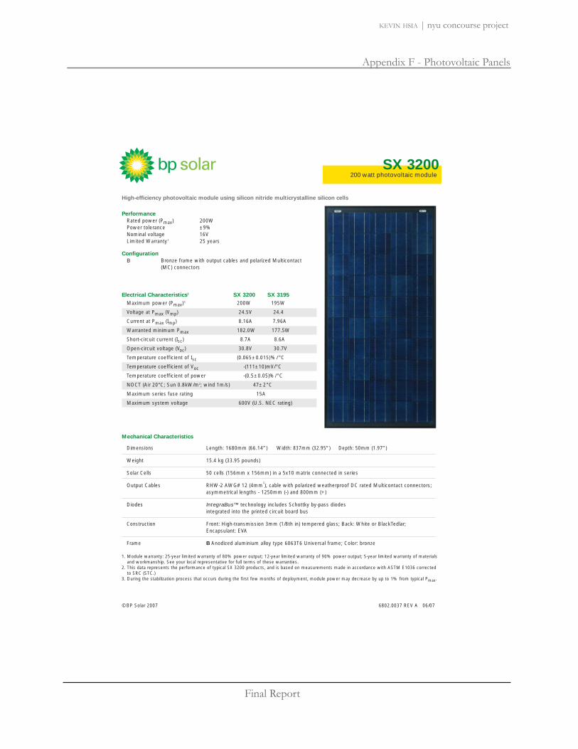
Final Report
Appendix F - Photovoltaic Panels
kevin hsia | nyu concourse project
200 watt photovoltaic module SX 3200
6802.0037 REV A 06/07©BP Solar 2007
High-efficiency photovoltaic module using silicon nitride multicrystalline silicon cells
Mechanical Characteristics
Dimensions Length: 1680mm (66.14”) Width: 837mm (32.95”) Depth: 50mm (1.97”)
Weight 15.4 kg (33.95 pounds)
Solar Cells 50 cells (156mm x 156mm) in a 5x10 matrix connected in series
Output Cables RHW-2 AWG# 12 (4mm2), cable with polarized weatherproof DC rated Multicontact connectors;
asymmetrical lengths - 1250mm (-) and 800mm (+)
Diodes IntegraBus™ technology includes Schottky by-pass diodes integrated into the printed circuit board bus
Construction Front: High-transmission 3mm (1/8th in) tempered glass; Back: White or BlackTedlar; Encapsulant: EVA
Frame B Anodized aluminium alloy type 6063T6 Universal frame; Color: bronze
Electrical Characteristics2 SX 3200 SX 3195Maximum power (Pmax)3 200W 195W
Voltage at Pmax (Vmp) 24.5V 24.4
Current at Pmax (Imp) 8.16A 7.96A
Warranted minimum Pmax 182.0W 177.5W
Short-circuit current (Isc) 8.7A 8.6A
Open-circuit voltage (Voc) 30.8V 30.7V
Temperature coefficient of Isc (0.065±0.015)%/ °C
Temperature coefficient of Voc -(111±10)mV/°C
Temperature coefficient of power -(0.5±0.05)%/°C
NOCT (Air 20°C; Sun 0.8kW/m2; wind 1m/s) 47±2°C
Maximum series fuse rating 15A
Maximum system voltage 600V (U.S. NEC rating)
PerformanceRated power (Pmax) 200WPower tolerance ±9%Nominal voltage 16VLimited Warranty1 25 years
ConfigurationB Bronze frame with output cables and polarized Multicontact
(MC) connectors
1. Module warranty: 25-year limited warranty of 80% power output; 12-year limited warranty of 90% power output; 5-year limited warranty of materialsand workmanship. See your local representative for full terms of these warranties.
2. This data represents the performance of typical SX 3200 products, and is based on measurements made in accordance with ASTM E1036 correctedto SRC (STC.)
3. During the stabilization process that occurs during the first few months of deployment, module power may decrease by up to 1% from typical Pmax.

Final Report
Appendix F - Photovoltaic Panels
kevin hsia | nyu concourse project
Quality and Safety Module power measurements calibrated to World Radiometric Reference through ESTI (European Solar Test Installation at Ispra, Italy)
Listed by Underwriter’s Laboratories for electrical and fire safety (Class C fire rating)
Included with each module: self-tapping grounding screw, instruction sheet and warranty documents.
6802.0037 06/07©BP Solar 2007
Module DiagramDimensions in brackets are in inches. Un-bracketed dimensions are in millimeters. Overall tolerances ±3mm (1/8”).
ESTI
Note: This publication summarizes product warranty and specifications, which are subject to change without notice. Additional information may be found on our web site: www.bpsolar.us
Qualification Test ParametersTemperature cycling range -40°C to +85°C (-40°F to 185°F)Humidity freeze, damp heat 85% RHStatic load front and back (e.g. wind) 2,400 pa (50psf) Front loading (e.g. snow) 5,400 pa (113psf)Haiilstone impact 25mm O (1 inch) at 23 m/s (52mph)
SX 3200 I-V Curves

Final Report
Appendix G - Time Current Graphs
kevin hsia | nyu concourse project
2 EATON CORPORATION Cutler-Hammer Series C F-Frame Circuit Breaker Trip Curves TC01200002E Effective: February 2008
AB DE-ION Circuit Breakers
FIGURE 1. TYPES EHD, FD AND HFD 15 AMPERES — CURVE NO. SC-4423-88A
Minimum Maximum
InterruptingRatingDeterminesEnd of Curve
100
50
30
20
10
5
3
2
1
.5
.3
.2
.1
.05
.03
.02
.01
.005
.003
.002
.001
TIME IN SECONDS
1,000
500
300
200
5,000
3,000
2,000
1 HO
UR
1 MIN
UT
E2 H
OU
RS
1000
0
8000
6000
9000
7000
5000
4000
3000
2000
1000800
600
900
700
500
400
300
200
1008060 907050403020109875 6
TIM
E IN
SEC
ONDS
10,000
100
50
30
20
10
5
3
2
1
.5
.3
.2
.1
.05
.03
.02
.01
.005
.003
.002
.001
1,000
500
300
200
5,000
3,000
2,000
1 H
OU
R1
MIN
UT
E2
HO
UR
S
CURRENT IN AMPERES
1000
0
8000
6000
9000
7000
5000
4000
3000
2000
1000
800
600
900
700
500
400
300
200
100
8060 907050403020109875 6
15A
Maximum SinglePole Trip Timesat 25°C 1
CURRENT IN AMPERES
Maximum Interrupting Time
�
Circuit Breaker Time/Current CurvesSeries C® F-Frame Circuit BreakersCatalog Types EHD, FD and HFD Circuit Breakers, One PoleFor application and coordination purposes only.Based on 40˚C ambient, cold start. Connected with four (4) feet ofrated wire (60˚C up to 100 amps, 75˚C above 125 amps) per terminal.Tested in open air.
Maximum AC Volts: 277 at 50/60 HzMaximum DC Volts: 125
Breaker RatingContinuous Instantaneous Trip, AmperesAmperes15 Amps See Curve
BreakerType
Symmetrical RMS Amperes (kA)
142565
EHDFDHFD
101010
Single pole test data at 25˚C based on NEMA Procedures(AB 2-1984) for verifying performance of molded case circuitbreakers.
277 Volts
Dc Amps
125 Volts
Interrupting Rating (UL/CSA Listed)

Final Report
Appendix G - Time Current Graphs
kevin hsia | nyu concourse project
52 EATON CORPORATION Cutler-Hammer Series C F-Frame Circuit Breaker Trip CurvesTC01200002E Effective: February 2008
FIGURE 51. TYPE FDC 175 – 225 AMPERES — CURVE NO. SC-6971-98
Maximum Singlele i ime
a � ➁
➀
Maximumi ime
Minimumi ime
➂➃
100
50
0
0
10
5
1
MS
MS
➀➁
➂➃
Circuit Breaker i e Curre t Cur ee Ca e Circuit Breaker
a al g e i ui ea e ee an u le a li a i n an ina i n u e nl
a e n am ien l a nne e i u ee a ei e e e minal e e in en ai i u en in all le
a i u C t aa i u C t
Breaker atin m e e n an ane u i u m e e MS
ea ee
S mme i al MS m e e u
ixe n e e ime e u en elea eSingle le e a a a � a e n M e u e
e i ing e man e M l e a e i ui ea eal e a i n ime
n e u ing a ing e e mine n u en i in e u i n egi n
e u e i a n n n � e en in in iegi n a e i la e al ng e u en axi a a n
a
terru ti ati
a a
te
175-225A
1 5 1 0 00 0050000
10000000 0000500000000100
1 5 1 0 00 0050000 10000000 0000500000000100

Final Report
Appendix G - Time Current Graphs
kevin hsia | nyu concourse project
Fixed Instantaneous Override �
100
50
30
20
10
5
3
2
1
.5
.3
.2
.1
.05
.03
.02
.01
.005
.003
.002
.001
TIME IN SECONDS
1,000
500
300
200
1 M
INU
TE
TIM
E IN
SEC
ONDS
10,000
100
50
30
20
10
5
3
2
1
.5
.3
.2
.1
.05
.03
.02
.01
.005
.003
.002
.001
1,000
500
300
200
5,000
3,000
2,000
1 H
OU
R1
MIN
UT
E2
HO
UR
S
Printed in U .S .A .
C u r v e N o . S C -6 7 5 1 -9 7October 1997
A pplication Data 2 9 -1 6 7 M SE 2 M ining S ervice C ir c u it B r e a k e r sCURRENT IN MULTIPLES OF RATING PLUG AMPERES (In)
100,
000
80,0
00
60,0
00
90,0
00
70,0
00
50, 0
00
40,0
00
30,0
00
20,0
00
10,0
00
8000
6000
9000
7000
5000
4000
3000201.8.6 .9.7.5 1086 975432
201.8.6 .9.7.5 1086 975432
CURRENT IN AMPERES
S hort DelayPick-U pS ettings
(Tolerance ± 10%)
For application and coordination purposes only. B ased on 40°C am bient, coldstart. Tested in open air with current in all poles .
Type E 2R E 2R MM axim um A c Volts : 600 at 60 Hz 1000Y /577 at 60 Hz
C ir c u it B r e a k e r Tim e /C u r r e n t C u r v e s (P h a s e C u r r e n t )�
E 2 M ining S ervice Circuit B reaker w ith Digitrip 310 E lectronicTrip U nit
Catalog Types E 2R and E 2R M Circuit B reakers , T hree Poles , Long-Instantaneous
Interrupting R atingDeterm ines E nd ofCurve �
N OT E S :
Curve accuracy applies from -20°C to +55°C am bient. For poss ible am perederating for am bient above 40°C, refer to Cutler-Ham m er.
Digitrip R M S 310 trip units are suitable for functional field testing with test kitCat. N o. S T K 2. For field testing use prim ary injection m ethods , follow N E M AA B 4 - 1991 publications .
� N ot U L/CS A Listed.� For high fault current levels a fixed instantaneous override is provided at 5,800A . (T olerance ± 15%).� T he end of the curve is determined by the interrupting rating of the circuit breaker. S ee above tabulation.
3X
4X
5X
6X
7X
S tandard FixedR ating Plug
Long Delay �M axim um Level
Clearing Tim e
Long Delay �M inim um Level
Clearing Tim e
Interrupting R ating (U L Lis ted)
@ 240V A c @ 480V A c @ 600V A c
E 2RE 2R M
125 6565
5050 25
B reakerType @ 1000Y /577 V A c
Instantaneous Pick-U p S etting� (A m peres)
E 2R or E 2R M A m peres 2 3 4 5 6 7 8
316T 33W 1600 3200 4800 6400 8000 4600 11200 12800320T 33W 2000 4000 6000 8000 10000 12000 14000 16000
Catalog N o. ContinuousB reaker R ating
CURRENT IN MULTIPLES OF RATING PLUG AMPERES (In)
Cutler-Hammer
2X
N P6645C79H01
E ngaged
R em ove
CH type
Digittrip RMS 310 Rating PlugFor Use to R Circuit Breaker Only
[
Cutler-Hammer
WestinghouseDigitalProtectionCell N o.Digitrip R M S 210
8X

Final Report
Appendix F - Photovoltaic Panels
kevin hsia | nyu concourse project
The Equipment
A full-scale ZeeWeed treatment facility is comprised of a givennumber of modular components: modules, cassettes, and trains.
A module is the basic building block and the heart of a ZeeWeedsystem. Each module contains thousands of horizontally strungmembrane fibers that have millions of microscopic pores in eachstrand. Water is filtered by applying a slight vacuum to the end ofeach fiber which draws the water through the tiny pores and into thefibers themselves. The pores form a physical barrier that allowsclean water to pass through while blocking unwanted material suchas suspended solids, bacteria, pathogens and certain viruses.
Modules are joined together to form a cassette, which is the smallestoperable unit of the filtration system. Each cassette can have avariety of module configurations depending on the amount of water that the cassette is required totreat.
Multiple cassettes are joined to form what is known as a process train. The train is a production unitcontaining a number of cassettes immersed in a membrane tank. Multiple process trains form aZeeWeed treatment plant.
ZeeWeed 500 Reinforced Ultrafiltration Membranes http://www.gewater.com/products/equipment/mf_uf_mbr/zeeweed_500.jsp
1 of 4 4/6/2009 4:05 AM

Final Report
Appendix F - Photovoltaic Panels
kevin hsia | nyu concourse project
Treatment Process
Feed water flows into the membrane tanks and treated water is drawn through the membranes duringProduction by applying a vacuum to the inside of the membrane fibers. The water removed bypermeation is replaced with feed water to maintain a constant level in the tank.
The particles that are rejected by the membrane pores remain in the process tank and are periodicallyremoved by a process called a Backwash (BW). During a backwash, filtered water reversed throughthe membrane fiber to dislodge any particles that may be physically lodged in the membrane fiber.Simultaneously, aeration scours any solids that are attached on the surface of the fibers.
To prevent fouling of the ZeeWeed membranes operators are required to perform regular maintenancecleans (MC). Maintenance cleaning begins by draining the membrane tank and soaking themembranes in a cleaning solution for several minutes. The solution is then drained and chemicalresidues are flushed from the membranes before the system resumes normal operation.
Coupling ZeeWeed to Upstream Processes
ZeeWeed membrane systems can remove particles that are larger than the pores on the membranefiber. Contaminants that exist in dissolved form, or are smaller than the pore size, can also be removedby the membranes if they are first transformed into insoluble species or larger particles. Treatmentprocesses commonly coupled to ZeeWeed to accomplish such conversions include enhancedcoagulation and oxidation.
Typical Applications
Membrane Bioreactor (MBR)Tertiary FiltrationRemoval of turbidity, bacteria, viruses and cystsRemoval of iron and manganeseRemoval of organics, color and THM precursorsTreatment of filter backwashRetrofit of conventional multi-media filtersPretreatment for reverse osmosisEmergency response systemsMobile systems
Treatment Results
Potable/Process Water
Turbidity < 0.05 NTU
Bacteria > 4 log removal
Giardia Cysts > 4 log removal
Cryptosporidium Oocysts > 4 log removal
Virus Rejection > 2.5 log
Total Suspended Solids < 1 mg/L
Total Organic Carbon 50-90% removal*
Color < 5 PCU
Iron < 0.05 mg/L
Manganese < 0.02 mg/L
SDI < 1
Wastewater Effluent (As part of a Membrane Bioreactor process)
ZeeWeed 500 Reinforced Ultrafiltration Membranes http://www.gewater.com/products/equipment/mf_uf_mbr/zeeweed_500.jsp
2 of 4 4/6/2009 4:05 AM

Final Report
Appendix F - Photovoltaic Panels
kevin hsia | nyu concourse project
BOD < 2 mg/L
TSS < 2 mg/L
NH3-N < 0.5 mg/L
TN < 3 mg/L**
TP < 0.05 mg/L**
Turbidity < 0.2 NTU
Fecal Coliform < 10 CFU/100 mL
Transmisivity > 75%
* with coagulant addition
** with appropriate design and/or chemical addition
The advantages of ZeeWeed low-pressure membranes include:
Reduced lifecycle costs and extended membranelife;Simplified design and operation;Smaller footprints with reduced land acquisitioncosts;Outside-in flow path provides a more robustsystem;Consistent performance through virtually anychange in raw water quality.
ZeeWeed 500 Series
Reinforced structure ensures long lifeHighest solids tolerance of any hollow fibermembraneWorks through virtually any raw water qualitychange or upsetDoes not require preclarification
Benefits to You
The advantages of ZeeWeed low-pressure membranesinclude:
Reduced lifecycle costs and extended membrane life;Simplified design and operation;Smaller footprints with reduced land acquisition costs;Outside-in flow path provides a more robust system;Consistent performance through virtually any change inraw water quality.
ZeeWeed 500 Series
Reinforced structure ensures long lifeHighest solids tolerance of any hollow fiber membraneWorks through virtually any raw water quality change orupsetDoes not require preclarification
CONTACT US
Contact us to learn more about whatwe can do for you.
ZeeWeed 500 Reinforced Ultrafiltration Membranes http://www.gewater.com/products/equipment/mf_uf_mbr/zeeweed_500.jsp
3 of 4 4/6/2009 4:05 AM

Final Report
Appendix I - Drawings
kevin hsia | nyu concourse project
L101 - Gould Plaza Lighting PlanL201 - Tisch Lobby Lighting Floor PlanL202 - Tisch Lobby Lighting Reflected Ceiling PlanL301 - Classroom Lighting Reflected Ceiling PlanL401 - MBA Student Lounge Reflected Ceiling Plan
E101 - Gould Plaza Electrical PlanE201 - Tisch Lobby Electrical PlanE301 - Classroom Electrical Plan E401 - MBA Student Lounge Electrical Plan