Filtered Talbot lens: Producing λ/2n-periodic atomic patterns with standing-wave fields having...
7
arXiv:physics/9909044v1 [physics.atom-ph] 21 Sep 1999 Filtered Talbot lens: Producing λ/2n-periodic atomic patterns with standing wave fields having period λ J. L. Cohen, B. Dubetsky, and P. R. Berman Physics Department, University of Michigan, Ann Arbor, MI 48109-1120 J. Schmiedmayer Institut f¨ ur Experimentalphysik, Universit¨ at-Innsbruck, Technikerstrasse 25, A-6020 Innsbruck, Austria (February 2, 2008) We propose a scheme to create high-contrast, periodic atom density distributions having period λ/2n using the Talbot effect, where λ is the wave length of the optical fields that scatter the atoms and n is a positive integer. This filtered Talbot lens is comprised of two standing-wave optical fields. An atomic beam propagates perpendicular to the fields. The first field, which is far-detuned from the atomic transition frequency, acts as an array of lenses that focuses the atoms. The second field, positioned at the atom optical focus of the first, is resonant with the atomic transition frequency and acts as an amplitude mask, leaving unperturbed only those atoms that pass through its nodes. At distances following the interaction with the second field that are equal to an integral fraction of the Talbot length, atomic density gratings having period λ/2n are formed. 03.75.Be, 32.80.Lg, 39.20.+q I. INTRODUCTION Over the past several years, considerable progress has been made in the manipulation of atoms by optical fields. One important application of this new technology is the focusing and deposition of atoms on substrates [1,2]. Us- ing standing wave optical fields having wavelength λ, one has been able to write a periodic array of lines or dots having period λ/2. The atomic ”lines” or ”dots” them- selves have widths w that are very small compared with λ/2; widths (half width at half maximum) as small as 6.5 nm have been achieved [3]. With such a resolution, one can envision writing structures having periods as small as λ/2n, where n, the atomic grating order, can be as large as n max ∼ λ/4w ∼ 25. (1) Although periods as small as λ/2n max are consistent with the resolution achieved to date, it is not obvious how one can use optical fields having wavelength λ to pro- duce such periodic structures. For example, focusing by standing wave fields results in periods equal to λ/2, or possibly λ/4 if cross-polarized counterpropagating waves are used [4]. A similar periodicity can be expected us- ing optical masks [5], in which only those atoms passing through the nodes of a standing wave field are registered on a substrate. There have been a number of proposals for producing sub-λ or higher-order atomic density gratings, which nec- essarily involve nonlinear interactions of the atoms with the fields. Atom interference [6] allows one to exploit photon echo techniques to isolate higher order gratings at specific focal planes following the interaction of an atomic beam with two or more standing wave fields [7,8]. High-order Bragg scattering of an atomic beam by stand- ing wave fields has produced structures with periods as small as λ/6 [9]. Counterpropagating waves, detuned from one another by an appropriate ratio, can be used to create arbitrarily high order gratings with good contrast [10]. It is even possible to achieve higher order gratings using the standard focusing or optical mask geometries, if one is able to exploit the Talbot or self-imaging effect [11] In atom optics the Talbot effect was observed us- ing microfabricated structures to scatter atoms [12]. When atoms propagating along the z axis pass through a microfabricated structure having period λ/2 in the x−direction, the atomic spatial distribution becomes a periodic function of z having period equal to the Talbot length L T = λ 2 /2λ dB , where λ dB = h/Mu is the atomic de Broglie wavelength, and M and u are atomic mass and speed, respectively. In other words, self images of the mi- crofabricated grating are produced at integral multiples of the Talbot length. Moreover, for a microfabricated structure with duty cycle f (ratio of opening to period), periodic structures having order as high as λ/2f can be produced at integral fractions of the Talbot length [13]. Using this technique, 7th order gratings have been ob- served [14] using a metastable He beam passing through a microfabricated structure having period λ/2=6.55 μ and duty cycle f =0.1. Instead of microfabricated structures, one can use an optical mask to act as an amplitude grating for a beam of metastable atoms. In a typical experiment [5], a metastable atomic beam is sent through a standing wave field that is resonant with a transition originating on the metastable level (see Fig. 1). If the upper level is excited by the field, it decays to the ground state. By using a 1
Transcript of Filtered Talbot lens: Producing λ/2n-periodic atomic patterns with standing-wave fields having...

arX
iv:p
hysi
cs/9
9090
44v1
[ph
ysic
s.at
om-p
h] 2
1 Se
p 19
99
Filtered Talbot lens: Producing λ/2n-periodic atomic patterns with standing wave
fields having period λ
J. L. Cohen, B. Dubetsky, and P. R. BermanPhysics Department, University of Michigan, Ann Arbor, MI 48109-1120
J. SchmiedmayerInstitut fur Experimentalphysik, Universitat-Innsbruck,
Technikerstrasse 25, A-6020 Innsbruck, Austria(February 2, 2008)
We propose a scheme to create high-contrast, periodic atom density distributions having periodλ/2n using the Talbot effect, where λ is the wave length of the optical fields that scatter the atomsand n is a positive integer. This filtered Talbot lens is comprised of two standing-wave optical fields.An atomic beam propagates perpendicular to the fields. The first field, which is far-detuned fromthe atomic transition frequency, acts as an array of lenses that focuses the atoms. The second field,positioned at the atom optical focus of the first, is resonant with the atomic transition frequencyand acts as an amplitude mask, leaving unperturbed only those atoms that pass through its nodes.At distances following the interaction with the second field that are equal to an integral fraction ofthe Talbot length, atomic density gratings having period λ/2n are formed.
03.75.Be, 32.80.Lg, 39.20.+q
I. INTRODUCTION
Over the past several years, considerable progress hasbeen made in the manipulation of atoms by optical fields.One important application of this new technology is thefocusing and deposition of atoms on substrates [1,2]. Us-ing standing wave optical fields having wavelength λ, onehas been able to write a periodic array of lines or dotshaving period λ/2. The atomic ”lines” or ”dots” them-selves have widths w that are very small compared withλ/2; widths (half width at half maximum) as small as 6.5nm have been achieved [3]. With such a resolution, onecan envision writing structures having periods as smallas λ/2n, where n, the atomic grating order, can be aslarge as
nmax ∼ λ/4w ∼ 25. (1)
Although periods as small as λ/2nmax are consistent withthe resolution achieved to date, it is not obvious howone can use optical fields having wavelength λ to pro-duce such periodic structures. For example, focusing bystanding wave fields results in periods equal to λ/2, orpossibly λ/4 if cross-polarized counterpropagating wavesare used [4]. A similar periodicity can be expected us-ing optical masks [5], in which only those atoms passingthrough the nodes of a standing wave field are registeredon a substrate.
There have been a number of proposals for producingsub-λ or higher-order atomic density gratings, which nec-essarily involve nonlinear interactions of the atoms withthe fields. Atom interference [6] allows one to exploitphoton echo techniques to isolate higher order gratingsat specific focal planes following the interaction of anatomic beam with two or more standing wave fields [7,8].
High-order Bragg scattering of an atomic beam by stand-ing wave fields has produced structures with periods assmall as λ/6 [9]. Counterpropagating waves, detunedfrom one another by an appropriate ratio, can be used tocreate arbitrarily high order gratings with good contrast[10]. It is even possible to achieve higher order gratingsusing the standard focusing or optical mask geometries,if one is able to exploit the Talbot or self-imaging effect[11]
In atom optics the Talbot effect was observed us-ing microfabricated structures to scatter atoms [12].When atoms propagating along the z axis pass througha microfabricated structure having period λ/2 in thex−direction, the atomic spatial distribution becomes aperiodic function of z having period equal to the Talbotlength LT = λ2/2λdB, where λdB = h/Mu is the atomicde Broglie wavelength, andM and u are atomic mass andspeed, respectively. In other words, self images of the mi-crofabricated grating are produced at integral multiplesof the Talbot length. Moreover, for a microfabricatedstructure with duty cycle f (ratio of opening to period),periodic structures having order as high as λ/2f can beproduced at integral fractions of the Talbot length [13].Using this technique, 7th order gratings have been ob-served [14] using a metastable He beam passing througha microfabricated structure having period λ/2 = 6.55 µand duty cycle f = 0.1.
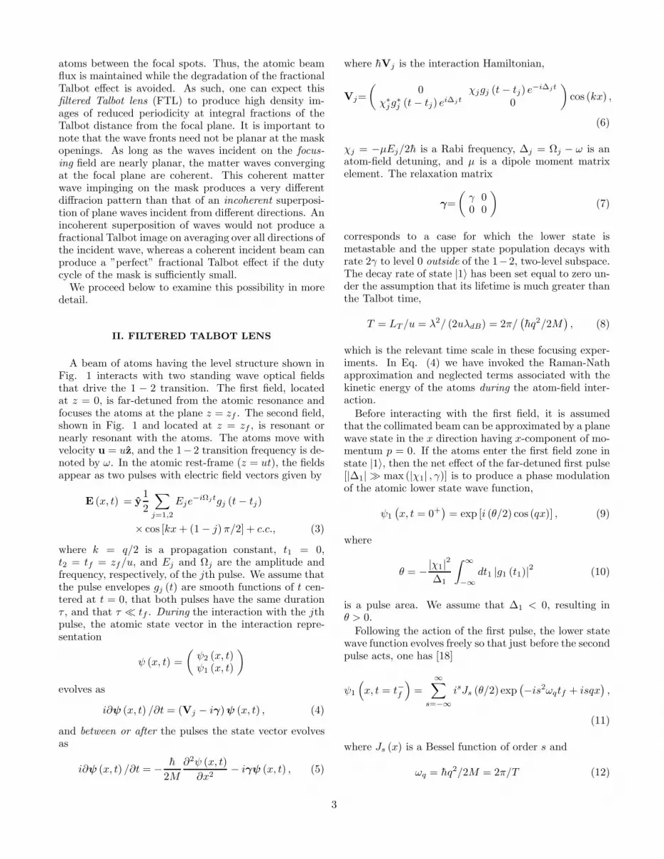
Instead of microfabricated structures, one can use anoptical mask to act as an amplitude grating for a beamof metastable atoms. In a typical experiment [5], ametastable atomic beam is sent through a standing wavefield that is resonant with a transition originating on themetastable level (see Fig. 1). If the upper level is excitedby the field, it decays to the ground state. By using a
1
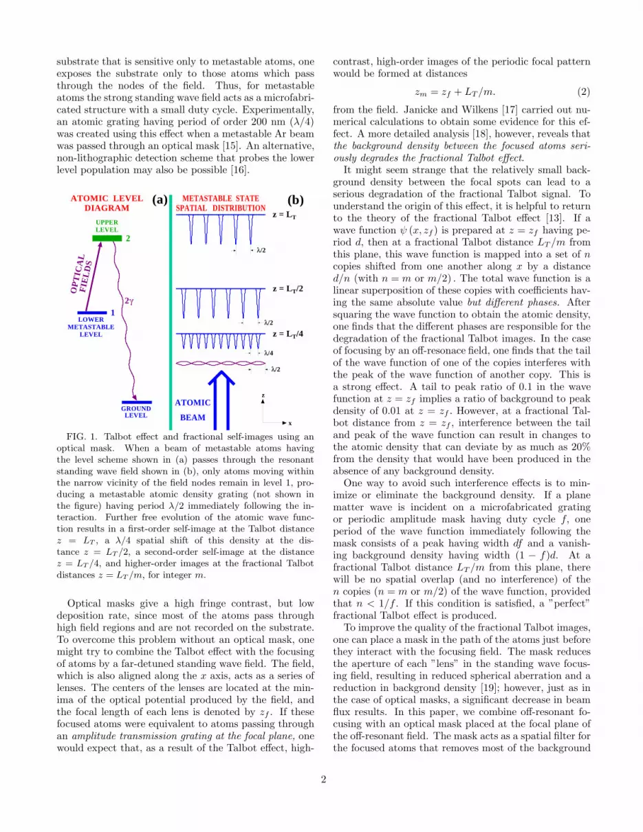
substrate that is sensitive only to metastable atoms, oneexposes the substrate only to those atoms which passthrough the nodes of the field. Thus, for metastableatoms the strong standing wave field acts as a microfabri-cated structure with a small duty cycle. Experimentally,an atomic grating having period of order 200 nm (λ/4)was created using this effect when a metastable Ar beamwas passed through an optical mask [15]. An alternative,non-lithographic detection scheme that probes the lowerlevel population may also be possible [16].
z = LT/4
METASTABLE STATESPATIAL DISTRIBUTION
z = LT/2
z = LT
ATOMIC LEVELDIAGRAM
UPPERLEVEL
LOWERMETASTABLE
LEVEL
1
2
2
FIE
LD
S
OP
TIC
AL
x
z
GROUND
/2
/4
/2
/2
(a) (b)
ATOMIC
BEAMLEVEL
FIG. 1. Talbot effect and fractional self-images using anoptical mask. When a beam of metastable atoms havingthe level scheme shown in (a) passes through the resonantstanding wave field shown in (b), only atoms moving withinthe narrow vicinity of the field nodes remain in level 1, pro-ducing a metastable atomic density grating (not shown inthe figure) having period λ/2 immediately following the in-teraction. Further free evolution of the atomic wave func-tion results in a first-order self-image at the Talbot distancez = LT , a λ/4 spatial shift of this density at the dis-tance z = LT /2, a second-order self-image at the distancez = LT /4, and higher-order images at the fractional Talbotdistances z = LT /m, for integer m.
Optical masks give a high fringe contrast, but lowdeposition rate, since most of the atoms pass throughhigh field regions and are not recorded on the substrate.To overcome this problem without an optical mask, onemight try to combine the Talbot effect with the focusingof atoms by a far-detuned standing wave field. The field,which is also aligned along the x axis, acts as a series oflenses. The centers of the lenses are located at the min-ima of the optical potential produced by the field, andthe focal length of each lens is denoted by zf . If thesefocused atoms were equivalent to atoms passing throughan amplitude transmission grating at the focal plane, onewould expect that, as a result of the Talbot effect, high-
contrast, high-order images of the periodic focal patternwould be formed at distances
zm = zf + LT/m. (2)
from the field. Janicke and Wilkens [17] carried out nu-merical calculations to obtain some evidence for this ef-fect. A more detailed analysis [18], however, reveals thatthe background density between the focused atoms seri-
ously degrades the fractional Talbot effect.It might seem strange that the relatively small back-
ground density between the focal spots can lead to aserious degradation of the fractional Talbot signal. Tounderstand the origin of this effect, it is helpful to returnto the theory of the fractional Talbot effect [13]. If awave function ψ (x, zf ) is prepared at z = zf having pe-riod d, then at a fractional Talbot distance LT /m fromthis plane, this wave function is mapped into a set of ncopies shifted from one another along x by a distanced/n (with n = m or m/2) . The total wave function is alinear superposition of these copies with coefficients hav-ing the same absolute value but different phases. Aftersquaring the wave function to obtain the atomic density,one finds that the different phases are responsible for thedegradation of the fractional Talbot images. In the caseof focusing by an off-resonace field, one finds that the tailof the wave function of one of the copies interferes withthe peak of the wave function of another copy. This isa strong effect. A tail to peak ratio of 0.1 in the wavefunction at z = zf implies a ratio of background to peakdensity of 0.01 at z = zf . However, at a fractional Tal-bot distance from z = zf , interference between the tailand peak of the wave function can result in changes tothe atomic density that can deviate by as much as 20%from the density that would have been produced in theabsence of any background density.
One way to avoid such interference effects is to min-imize or eliminate the background density. If a planematter wave is incident on a microfabricated gratingor periodic amplitude mask having duty cycle f, oneperiod of the wave function immediately following themask consists of a peak having width df and a vanish-ing background density having width (1 − f)d. At afractional Talbot distance LT /m from this plane, therewill be no spatial overlap (and no interference) of then copies (n = m or m/2) of the wave function, providedthat n < 1/f . If this condition is satisfied, a ”perfect”fractional Talbot effect is produced.
To improve the quality of the fractional Talbot images,one can place a mask in the path of the atoms just beforethey interact with the focusing field. The mask reducesthe aperture of each ”lens” in the standing wave focus-ing field, resulting in reduced spherical aberration and areduction in backgrond density [19]; however, just as inthe case of optical masks, a significant decrease in beamflux results. In this paper, we combine off-resonant fo-cusing with an optical mask placed at the focal plane ofthe off-resonant field. The mask acts as a spatial filter forthe focused atoms that removes most of the background
2
atoms between the focal spots. Thus, the atomic beamflux is maintained while the degradation of the fractionalTalbot effect is avoided. As such, one can expect thisfiltered Talbot lens (FTL) to produce high density im-ages of reduced periodicity at integral fractions of theTalbot distance from the focal plane. It is important tonote that the wave fronts need not be planar at the maskopenings. As long as the waves incident on the focus-
ing field are nearly planar, the matter waves convergingat the focal plane are coherent. This coherent matterwave impinging on the mask produces a very differentdiffracion pattern than that of an incoherent superposi-tion of plane waves incident from different directions. Anincoherent superposition of waves would not produce afractional Talbot image on averaging over all directions ofthe incident wave, whereas a coherent incident beam canproduce a ”perfect” fractional Talbot effect if the dutycycle of the mask is sufficiently small.
We proceed below to examine this possibility in moredetail.
II. FILTERED TALBOT LENS
A beam of atoms having the level structure shown inFig. 1 interacts with two standing wave optical fieldsthat drive the 1 − 2 transition. The first field, locatedat z = 0, is far-detuned from the atomic resonance andfocuses the atoms at the plane z = zf . The second field,shown in Fig. 1 and located at z = zf , is resonant ornearly resonant with the atoms. The atoms move withvelocity u = uz, and the 1− 2 transition frequency is de-noted by ω. In the atomic rest-frame (z = ut), the fieldsappear as two pulses with electric field vectors given by
E (x, t) = y1
2
∑
j=1,2
Eje−iΩjtgj (t− tj)
× cos [kx+ (1 − j)π/2] + c.c., (3)
where k = q/2 is a propagation constant, t1 = 0,t2 = tf = zf/u, and Ej and Ωj are the amplitude andfrequency, respectively, of the jth pulse. We assume thatthe pulse envelopes gj (t) are smooth functions of t cen-tered at t = 0, that both pulses have the same durationτ , and that τ ≪ tf . During the interaction with the jthpulse, the atomic state vector in the interaction repre-sentation
ψ (x, t) =
(
ψ2 (x, t)ψ1 (x, t)
)
evolves as
i∂ψ (x, t) /∂t = (Vj − iγ)ψ (x, t) , (4)
and between or after the pulses the state vector evolvesas
i∂ψ (x, t) /∂t = − h
2M
∂2ψ (x, t)
∂x2− iγψ (x, t) , (5)
where hVj is the interaction Hamiltonian,
Vj=
(
0 χjgj (t− tj) e−i∆jt
χ∗
jg∗
j (t− tj) ei∆jt 0
)
cos (kx) ,
(6)
χj = −µEj/2h is a Rabi frequency, ∆j = Ωj − ω is anatom-field detuning, and µ is a dipole moment matrixelement. The relaxation matrix
γ=
(
γ 00 0
)
(7)
corresponds to a case for which the lower state ismetastable and the upper state population decays withrate 2γ to level 0 outside of the 1−2, two-level subspace.The decay rate of state |1〉 has been set equal to zero un-der the assumption that its lifetime is much greater thanthe Talbot time,
T = LT /u = λ2/ (2uλdB) = 2π/(
hq2/2M)
, (8)
which is the relevant time scale in these focusing exper-iments. In Eq. (4) we have invoked the Raman-Nathapproximation and neglected terms associated with thekinetic energy of the atoms during the atom-field inter-action.
Before interacting with the first field, it is assumedthat the collimated beam can be approximated by a planewave state in the x direction having x-component of mo-mentum p = 0. If the atoms enter the first field zone instate |1〉, then the net effect of the far-detuned first pulse[|∆1| ≫ max (|χ1| , γ)] is to produce a phase modulationof the atomic lower state wave function,
ψ1
(
x, t = 0+)
= exp [i (θ/2) cos (qx)] , (9)
where
θ = −|χ1|2∆1
∫
∞
−∞
dt1 |g1 (t1)|2 (10)
is a pulse area. We assume that ∆1 < 0, resulting inθ > 0.
Following the action of the first pulse, the lower statewave function evolves freely so that just before the secondpulse acts, one has [18]
ψ1
(
x, t = t−f
)
=
∞∑
s=−∞
isJs (θ/2) exp(
−is2ωqtf + isqx)
,
(11)
where Js (x) is a Bessel function of order s and
ωq = hq2/2M = 2π/T (12)
3

is a two-photon recoil frequency. When γtf ≫ 1, one canneglect the small upper state amplitude at t = tf . Theatoms are assumed to be focused at the time tf (distancezf = utf ) to lines centered at x = 2πs/q for integer s.
To determine the effect of pulse 2, one must solve Eq.(4) with j = 2, subject to the initial condition
ψ− =
(
0
ψ1
(
x, t = t−f
)
)
. (13)
An analytic solution can be obtained if we assume that|g2 (t) /g2 (t)| ≪ γ or
τ ≫ γ−1. (14)
Condition (14) is desirable as it guarantees that atomswill have time to decay out of the two-state subspace dur-ing the interaction with the second field pulse. Moreover,it is sufficient to satisfy the adiabatic condition
τ ≫ min(
γ−1, |2χ2|−1, |∆2|−1
)
. (15)
As a result, the pulse turns on sufficiently slowly toensure that instantaneous eigenstates of the complex”Hamiltonian”, h (V2 − iγ) are approximate eigenstatesof the system. In this manner the lower state wave func-tion following the second pulse’s action is given by
ψ1
(
x, t = t+f
)
≈ η(x)ψ1
(
x, t = t−f
)
, (16)
where
η (x) = expi
2
∫
∞
−∞
dt1 [∆2 + iγ
−(
(∆2 + iγ)2
+ 4 |χ2g2 (t1)|2 sin2 (kx))1/2
]
(17)
is the transmission function associated with the opticalmask.
Following the second pulse, the lower state againevolves freely. When the masking field is on exact reso-nance (∆2 = 0) and weak (|χ2| /γ ≪ 1), one finds
η(x) = exp[
−β sin2 (kx)]
, (18)
where
β =|χ2|2γ
∫
∞
−∞
dt1 |g2 (t1)|2 (19)
is the area associated with pulse 2. Expanding expres-sion (18) in plane waves and keeping in mind that eachplane wave eisqx acquires the time-dependent phase fac-
tor e−is2ωq(t−tf ) for t > tf , one obtains
ψ1 (x, t) = e−β/2∑
s1,s2
is1Js1(θ/2) Is2
(β/2)
exp
−iωq
[
s21tf + (s1 + s2)2(t− tf )
]
+i (s1 + s2) qx , (20)
where Is (x) is a modified Bessel function of orders. From this expression, using an addition theoremfor Bessel functions, one finds that the atom density,ρ (x, t) = |ψ (x, t)|2, is given by
ρ (x, t) = e−β∑
s1,s2
Js1θ sin [ωq (s1t+ s2 (t− tf ))]
×Is2β cos [ωq (s1 + s2) (t− tf )] ei(s1+s2)qx. (21)
Expressions (11), (20), and (21) are convenient for nu-merical evaluation of the atomic wave function and den-sity. On the other hand, they do not reveal in any trans-parent fashion the density peaks at the focal plane t = tfand the high-order harmonic density patterns at the frac-tional Talbot times
tm = tf + T/m. (22)
Both of these features are more readily apparent if wefollow alternative approaches. First, instead of Eq. (11),one can use approximate expressions for the focal planeposition and atom density profile in the asymptotic limitof
√θ ≫ 1 [18],
tf ∼ ω−1q θ−1
(
1 + 1.27θ−1/2)
, (23a)
ρ (x, tf ) ∼∞∑
s=−∞
√3θ
π
×∣
∣
∣f(
31/4θ3/4 (qx− 2πs) ,−2.20)∣
∣
∣
2
, (23b)
f (x, ω) =
∫
∞
−∞
dξ exp(
−ixξ + iωξ2 + iξ4)
. (23c)
Equation (23b) is valid within the small regions near thestanding wave nodes, |x− sλ/2| <∼ λθ−3/4.
Second, one can also obtain alternative expressions forthe atomic density at the fractional Talbot times. Equa-tion (21) is valid for arbitrary t > tf . However, if thetime is restricted to be a rational fraction of the Talbottime after the focus [20],
t = tf + (ℓ/m)T, (24)
for integer ℓ and m, a derivation, similar to the one givenin Ref. [13], leads to
ψ1 (x, t) =m−1∑
s=0
asψ1(x− sλ/2m, t = t+f ), (25a)
as = (2im)−1ℓ∑
s′=0
exp[
iπ (s+ms′)2/2m
]
, (25b)
valid in the interval 0 ≤ x < λ/2. The wave function atthese times (24) appears as a superposition of m scaled
4
images of the filtered wave function at the focal time. Informing the atomic density,
ρ (x, t) = |ψ1 (x, t)|2 , (26)
it is possible for different terms in the sum over s to inter-fere. (In the absence of the optical mask (β = 0), theseinterference terms cause significant density oscillationsthat ruin the fractional self-image of the atoms focusedby the far-detuned field.) However, if the optical mask attf produces very narrow structures with an effective dutycycle much less than unity, then the interference termsare unimportant and the density reduces to
ρ (x, t) =
m−1∑
s=0
|as|2∣
∣
∣ψ1(x− sλ/2m, t = t+f )
∣
∣
∣
2
. (27)
When valid, the spatial distribution (27) becomes anexact nth-order image of the density at tf when all non-zero coefficients (25b) have the same absolute value. Thiscan occur at the fractional Talbot times
tm = tf + (T/m), (28)
with ℓ = 1 in Eq. (24). At these times, the coefficientsbecome
|as| = (2/m)1/2
|cos (mπ/4)| , for even s|sin (mπ/4)| , for odd s
(29)
Three cases can be distinguished [13]:
(a) m = 2n′ + 1, (30a)
(b) m = 2 (2n′ + 1) , (30b)
(c) m = 4n′, (30c)
where n′ is a positive integer. In case (a), |as|2 =1/m for all s, leading to atomic densities having period
λ/ [2 (2n′ + 1)]. In case (b), |as|2 = 2/m for odd s and
|as|2 = 0 for even s, leading to atomic densities havingperiod λ/ [2 (2n′ + 1)] but that are shifted by half a pe-
riod from those of case (a). In case (c), |as|2 = 2/m for
even s and |as|2 = 0 for odd s, leading to densities havingperiod λ/4n′.
For the FTL scheme to produce high-quality, high-contrast fractional self-images, it is sufficient that threeconditions are met. First, the focused atoms at tf musthave a large density (ρ (x, tf ) ≫ 1) at the positionsx = 2πs/q. For θ ≫ 1, the peak density can be estimatedto grow as 3.83θ1/2 according to an analysis of Eq. (23b)[18]. Second, the focal spot size 2w ≈ 0.118λθ−3/4 [18]should be less than λ/2m for case (a) and less than λ/mfor cases (b) and (c). Thus, the effective duty cycle ofthe focused atom density over the λ/2 period is
f ≃ 4w/λ ≈ 0.237θ−3/4, (31)
giving a maximum possible grating order on its own of
nmax ≃ f−1 ≈ 4.22θ3/4. (32)
Third, for Eq. (27) to be valid so that interferenceterms in the focused atom wave function do not de-grade the fractional images at later times, the opticalmask should only pick out the density peaks and clipthe tails of the unavoidable background wave functionbetween the peaks. If we wish to use most of the fo-cused atoms, the optical mask slit width or opening sizeδx should not be smaller than the focused atom spotsize 2w. From Eq. (18), it follows that the transmissionfunction near the nodes for |χ2| /γ ≪ 1 and ∆2 = 0 is
η(x) ≃ exp[
−β (kx)2]
, from which we can estimate that
the effective opening size δx is
δx ≃(
ln 2
β
)1/2λ
π≈ 0.265
λ
β1/2.
Setting δx >∼ 2w, one finds the upper limit for β
β < 5.04θ3/2. (33)
To establish a lower limit for β, one must examine Eqs.(11, 18, 25, 27) numerically for given values of θ and m.We have found that a value of β an order of magnitudesmaller than the upper limit given by Eq. (33) can stillgive rise to high contrast gratings.
III. DISCUSSION
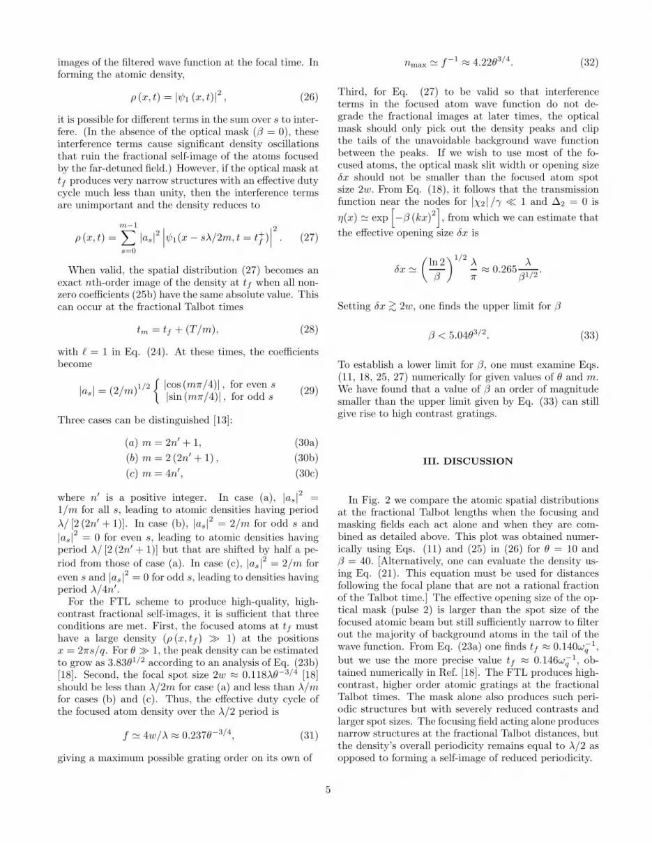
In Fig. 2 we compare the atomic spatial distributionsat the fractional Talbot lengths when the focusing andmasking fields each act alone and when they are com-bined as detailed above. This plot was obtained numer-ically using Eqs. (11) and (25) in (26) for θ = 10 andβ = 40. [Alternatively, one can evaluate the density us-ing Eq. (21). This equation must be used for distancesfollowing the focal plane that are not a rational fractionof the Talbot time.] The effective opening size of the op-tical mask (pulse 2) is larger than the spot size of thefocused atomic beam but still sufficiently narrow to filterout the majority of background atoms in the tail of thewave function. From Eq. (23a) one finds tf ≈ 0.140ω−1
q ,
but we use the more precise value tf ≈ 0.146ω−1q , ob-
tained numerically in Ref. [18]. The FTL produces high-contrast, higher order atomic gratings at the fractionalTalbot times. The mask alone also produces such peri-odic structures but with severely reduced contrasts andlarger spot sizes. The focusing field acting alone producesnarrow structures at the fractional Talbot distances, butthe density’s overall periodicity remains equal to λ/2 asopposed to forming a self-image of reduced periodicity.
5

12
45
31
23
45
12
34
12
3
4 44 40 0
m = 4 m = 6
m = 5 m = 16
x x
(x,z
f+
LT/m
)
FIG. 2. Filtered Talbot lens production of high-orderatomic density patterns (solid lines) at distances zf + LT /mfor a mask parameter β = 40 in the weak field regime|χ2| /γ ≪ 1 ≪ γτ. For comparison, we show the spatial dis-tributions of the metastable atomic density produced by theoptical mask alone at the fractional Talbot distances (dashedlines) and by the focusing field alone at the fractional Tal-bot distances from the focal plane (dot-dashed lines). For allplots, the focusing field area θ is equal to 10.
Within the confines of the Raman-Nath approxima-tion, it might be difficult to achieve a value β = 40 if|χ2| ≪ γ. For example, when |χ2| /γ ∼ 0.1, one needs γτto be as large as 4×10³. For γ/ωq ∼ 103 this implies val-ues of ωqτ > 1, which are inconsistent with the Raman-Nath approximation. To avoid this difficulty, smaller val-ues of γτ can be used with larger Rabi frequencies. Letus assume that field 2, the standing wave mask, is a res-onant, rectangular pulse with |χ2| /γ ≫ 1 and that theadiabatic condition (15) is satisfied [21]. Then, except inthe vicinity of the nodes, the transmission function (17)is
η (x) = exp(i |χ2τ sin (kx)| − γτ/2). (34)
From this expression, a value of γτ ∼ 3 − 4 is enough toattenuate the tails of the focused atoms with an accuracyof several percent. Near the nodes, |χ2 sin (kx)| ≪ γ, andEq. (19) is still valid. As a result, large values of an ef-fective β are possible for |χ2| /γ ≫ 1 even if γτ is on theorder of unity.
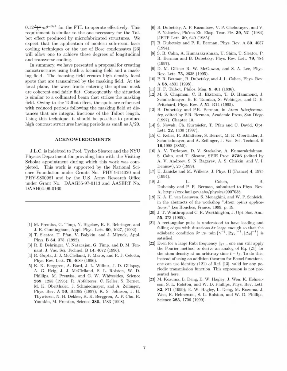
In Fig. 3 we plot the atom density profiles at fractionalTalbot distances with γτ = 4 and θ = 10. The plot hasbeen obtained by combining Eqs. (11), (16), (17), and(25) [22]. We have found that the amplitudes of the dif-ferent peaks between x = 0 and x = λ/2 in the fractionalTalbot effect oscillate slightly as a function of |χ2| . Theorigin of these Rabi-like oscillations is an interference ofthe m terms in Eq. (25a), each of which has a differentphase that depends on the Rabi frequency χ2. For eachm
we have chosen a value of the parameter |χ2| τ that min-imizes these oscillations to provide as pure a fractionalself-image as possible.
12
34
51
23
45
12
34
12
3
0-4
-44
04
m=4, | 2| = 10.14 m=6, | 2| = 15.92
m=5, | 2| = 23.76 m=16, | 2| = 30.59
(x,z
f+
LT/m
)
x xFIG. 3. The same type of density plots as those shown in
Fig. 2, but for a moderate value of the upper state decay rate(γτ = 4) and a large value of the optical mask Rabi frequency|χ2/γ| > 1 The parameter |χ2τ | is chosen for each plot byrequiring that the ratio of the maximum and minimum am-plitudes of the peaks in the fractional density pattern are asclose as possible to unity. In each case this choice producesthe best nth-order fractional self-image with the filtered Tal-bot lens. For all plots, the focusing field area θ is equal to10.
Chromatic aberration and atomic beam angular diver-gence degrade the focusing and the Talbot effect. Chro-matic aberration arises as a result of a distribution oflongitudinal velocities in the atomic beam. Recently, thiseffect was considered in detail for thin lens atom focus-ing [18]. It was shown that, owing to the finite depth offocus, the focusing is not seriously degraded for θ ≈ 10until the spread in velocities divided by the average ve-locity, ∆v/u, exceeds 0.1. For larger values of ∆v/u, ournumerical results indicate that high-order atomic grat-ings are still produced, but a background density ariseswhose amplitude starts to be comparable with the peaksof the fractional Talbot spots.
Angular divergence in the beam provides a more se-vere restriction. If atoms move at an angle φ relative tothe z axis, the atomic distribution will be displaced byδx ∼ φLT /m when the beam travels a distance equalto LT /m. This displacement has to be smaller than thewidth of the peak in the focused atomic distribution ifwe want to maintain the beam flux and produce high-contrast, mth-order patterns. From Eq. (23b) one candeduce [18] that the half-width of the distribution is ap-proximately equal to 0.06λθ−3/4. From this expressionone finds that the angular divergence φ must be less than
6
0.12λdB
λ mθ−3/4 for the FTL to operate effectively. Thisrequirement is similar to the one necessary for the Tal-bot effect produced by microfabricated structures. Weexpect that the application of modern sub-recoil lasercooling techniques or the use of Bose condensates [23]will allow one to achieve these degrees of longitudinaland transverse cooling.
In summary, we have presented a proposal for creatingnanostructures using both a focusing field and a mask-ing field. The focusing field creates high density focalspots that are transmitted by the masking field. At thefocal plane, the wave fronts entering the optical maskare coherent and fairly flat. Consequently, the situationis similar to a collimated beam that strikes the maskingfield. Owing to the Talbot effect, the spots are refocusedwith reduced periods following the masking field at dis-tances that are integral fractions of the Talbot length.Using this technique, it should be possible to producehigh contrast structures having periods as small as λ/20.
ACKNOWLEDGMENTS
J.L.C. is indebted to Prof. Tycho Sleator and the NYUPhysics Department for providing him with the VisitingScholar appointment during which this work was com-pleted. This work is supported by the National Sci-ence Foundation under Grants No. PHY-9414020 andPHY-9800981 and by the U.S. Army Research Officeunder Grant No. DAAG55-97-0113 and AASERT No.DAAH04-96-0160.
[1] M. Prentiss, G. Timp, N. Bigelow, R. E. Behringer, andJ. E. Cunningham, Appl. Phys. Lett. 60, 1027, (1992).
[2] T. Sleator, T. Pfau, V. Balykin, and J. Mlynek, Appl.Phys. B 54, 375, (1992).
[3] R. E. Behringer, V. Natarajan, G. Timp, and D. M. Ten-nant, J. Vac. Sci. Technol. B 14, 4072 (1996).
[4] R. Gupta, J. J. McClelland, P. Marte, and R. J. Celotta,Phys. Rev. Lett. 76, 4689 (1996).
[5] K. K. Berggren, A. Bard, J. L. Wilbur, J. D. Gillapsy,A. G. Heig, J. J. McClelland, S. L. Rolston, W. D.Phillips, M. Prentiss, and G. W. Whitesides, Science269, 1255 (1995); R. Abfalterer, C. Keller, S. Bernet,M. K. Oberthaler, J. Schmiedmayer, and A. Zeilinger,Phys. Rev. A 56, R4365 (1997); K. S. Johnson, J. H.Thywissen, N. H. Dekker, K. K. Berggren, A. P. Chu, R.Younkin, M. Prentiss, Science 280, 1583 (1998).
[6] B. Dubetsky, A. P. Kazantsev, V. P. Chebotayev, and V.P. Yakovlev, Pis’ma Zh. Eksp. Teor. Fiz. 39, 531 (1984)[JETP Lett. 39, 649 (1985)].
[7] B. Dubetsky and P. R. Berman, Phys. Rev. A 50, 4057(1994).
[8] S. B. Cahn, A. Kumarakrishnan, U. Shim, T. Sleator, P.R. Berman and B. Dubetsky, Phys. Rev. Lett. 79, 784(1997).
[9] D. M. Giltner R. W. McGowan, and S. A. Lee, Phys.Rev. Lett. 75, 2638 (1995).
[10] P. R. Berman, B. Dubetsky, and J. L. Cohen, Phys. Rev.A 58, 4801 (1998).
[11] H. F. Talbot, Philos. Mag. 9, 401 (1836).[12] M. S. Chapman, C. R. Ekstrom, T. D. Hammond, J.
Schmiedmayer, B. E. Tannian, S. Wehinger, and D. E.Pritchard, Phys. Rev. A 51, R14 (1995).
[13] B. Dubetsky and P.R. Berman, in Atom Interferome-
try, edited by P.R. Berman, Academic Press, San Diego(1997), Chapter 10.
[14] S. Nowak, Ch. Kurtsiefer, T. Pfau and C. David, Opt.Lett. 22, 1430 (1997).
[15] C. Keller, R. Abfalterer, S. Bernet, M. K. Oberthaler, J.Schmiedmayer, and A. Zeilinger, J. Vac. Sci. Technol. B16,1998 (3850).
[16] A. V. Turlapov, D. V. Strekalov, A. Kumarakrishnan,S. Cahn, and T. Sleator, SPIE Proc. 3736 (edited byA. V. Andreev, S. N. Bagayev, A. S. Chirkin, and V. I.Denisov), 26 (1999).
[17] U. Janicke and M. Wilkens, J. Phys. II (France) 4, 1975(1994).
[18] J. L. Cohen, B.Dubetsky and P. R. Berman, submitted to Phys. Rev.A, http://xxx.lanl.gov/abs/physics/9907038.
[19] K. A. H. van Leeuwen, S. Meneghini, and W. P. Schleich,in the abstracts of the workshop ”Atom optics applica-
tions,” Les Houches, France, 1999, p. 19.[20] J. T. Winthrop and C. R. Worthington, J. Opt. Soc. Am.,
55, 373 (1965).[21] A rectangular pulse is understood to have leading and
falling edges with durations δτ large enough so that theadiabatic condition δτ ≫ min
(
γ−1, |2χ2|−1 , |∆2|
−1)
issatisfied.
[22] Even for a large Rabi frequency |χ2| , one can still applythe Fourier method to derive an analog of Eq. (21) forthe atom density at an arbitrary time t− tf . To do this,instead of using an addition theorem for Bessel functions,one can use identity (121) of Ref. [13], valid for any pe-riodic transmission function. This expression is not pre-sented here.
[23] M. Kozuma, L. Deng, E. W. Hagley, J. Wen, K. Helmer-son, S. L. Rolston, and W. D. Phillips, Phys. Rev. Lett.82, 871 (1999); E. W. Hagley, L. Deng, M. Kozuma, J.Wen, K. Helmerson, S. L. Rolston, and W. D. Phillips,Science 283, 1706 (1999).
7