


I&T Ford Shop Service Manual - Series 2N 8N 9N FO-4 - Free
106
I&T Shop Service Ford Shop Manual Series 2N 8N 9N Manual NO. FO-4 copyright 1953 - EXPIRED This book free to print, share, distribute with anyone! Remastered Version 1.2
-
Upload
khangminh22 -
Category
Documents
-
view
1 -
download
0
Transcript of I&T Ford Shop Service Manual - Series 2N 8N 9N FO-4 - Free
I&T Shop Service
Ford Shop Manual Series 2N 8N 9N
Manual NO. FO-4
copyright 1953 - EXPIRED
This book free to print, share, distribute with anyone!
Remastered Version 1.2
FO-4 I&T (Remastered Ver.1.2 ) 05-24-2015
PREFACE
This book was transcribed, reformatted to this PDF version by me, John Chapman.
I'd be delighted for you to connect with me at any or all of:
Email: j [email protected]: http://twitter.com/jcchapsterLinked-In: https://www.linkedin.com/in/jcchapsterFacebook: https://www.facebook.com/thejcchapster
TRACTOR MANUAL ARCHIVE
I'm building a Tractor Manual Archive. The Tractor Manual Archive is a repository of Tractor Manuals that are typically out of Copyright, and are now in Public Domain. Additionally, manuals that have Copyright holder permission to be included will be archived as well.
Do you have an old manual? It might be a manual others are looking for. Contact the Tractor Manual Archive about how to share your manual with others, and be a part of preserving useful history.
Do you have a PDF of an old manual? Even if purchased, if it is out of copyright it can be shared.–
Email me to learn more, to participate, to download manuals as they become available.
ERRORS and OMMISSIONS If you discover an error with this manual, –please email: [email protected] and I will correct and release an updated version.- John Chapman / Tractor Manual Archive administrator
Connect/Report Errors – [email protected]
FO-4 I&T (Remastered Ver.1.2 ) 05-24-2015
Change log
5-23-2015 Corrected some images placements and typos. Moved to –version 1.1.
5-24-2015 Corrected some other minor issues. Moved to version –1.2.
Connect/Report Errors – [email protected]
FO-4 I&T (Remastered Ver.1.2 ) 05-24-2015
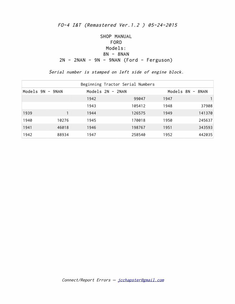
SHOP MANUAL FORD
Models: 8N - 8NAN
2N - 2NAN - 9N - 9NAN (Ford - Ferguson)
Serial number is stamped on left side of engine block.
Beginning Tractor Serial Numbers
Models 9N - 9NAN Models 2N - 2NAN Models 8N - 8NAN
1942 99047 1947 1
1943 105412 1948 37908
1939 1 1944 126575 1949 141370
1940 10276 1945 170018 1950 245637
1941 46018 1946 198767 1951 343593
1942 88934 1947 258540 1952 442035
Connect/Report Errors – [email protected]
FO-4 I&T (Remastered Ver.1.2 ) 05-24-2015
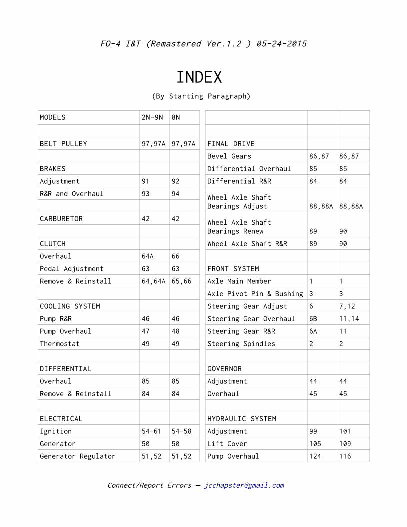
INDEX (By Starting Paragraph)
MODELS 2N-9N 8N
BELT PULLEY 97,97A 97,97A FINAL DRIVE
Bevel Gears 86,87 86,87
BRAKES Differential Overhaul 85 85
Adjustment 91 92 Differential R&R 84 84
R&R and Overhaul 93 94 Wheel Axle Shaft Bearings Adjust 88,88A 88,88A
CARBURETOR 42 42 Wheel Axle Shaft Bearings Renew 89 90
CLUTCH Wheel Axle Shaft R&R 89 90
Overhaul 64A 66
Pedal Adjustment 63 63 FRONT SYSTEM
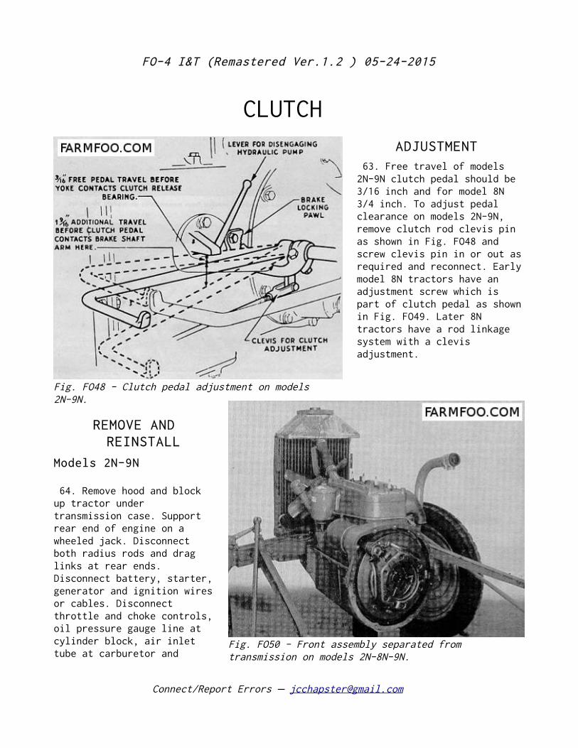
Remove & Reinstall 64,64A 65,66 Axle Main Member 1 1
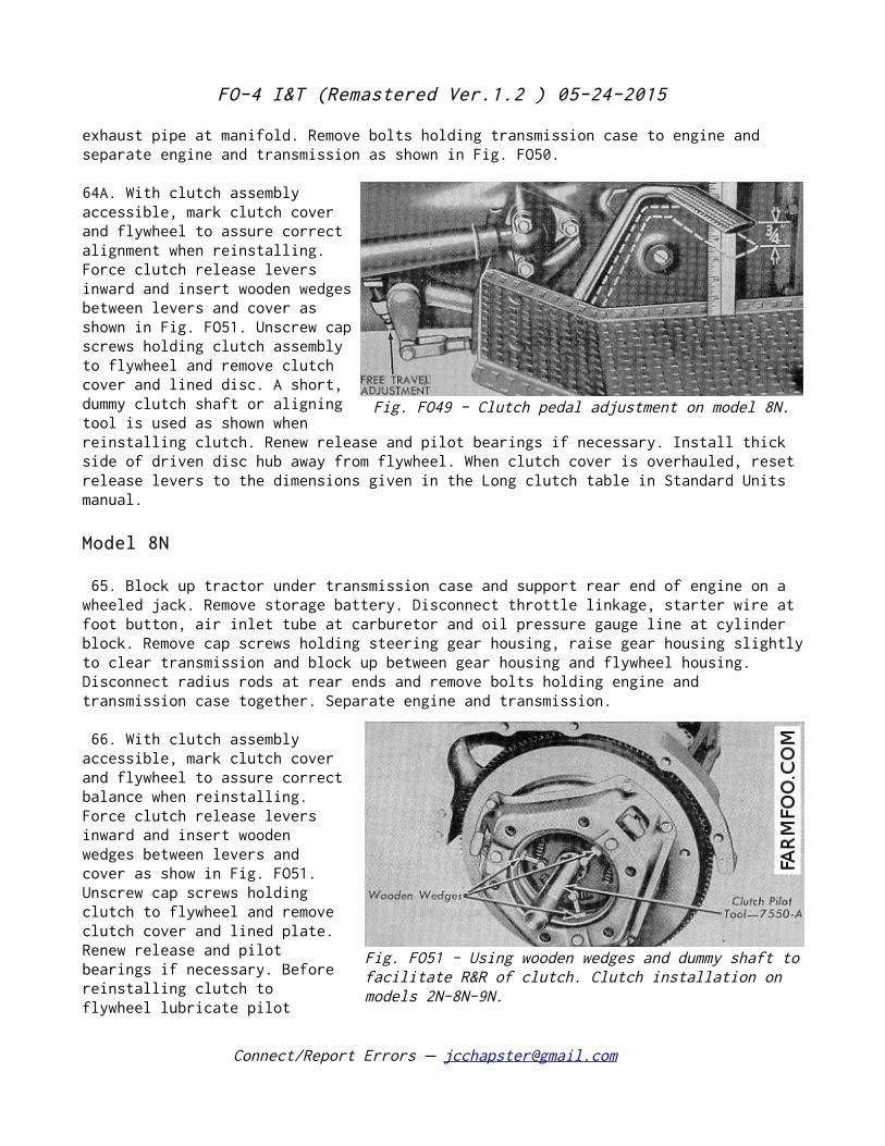
Axle Pivot Pin & Bushing 3 3
COOLING SYSTEM Steering Gear Adjust 6 7,12
Pump R&R 46 46 Steering Gear Overhaul 6B 11,14
Pump Overhaul 47 48 Steering Gear R&R 6A 11
Thermostat 49 49 Steering Spindles 2 2
DIFFERENTIAL GOVERNOR
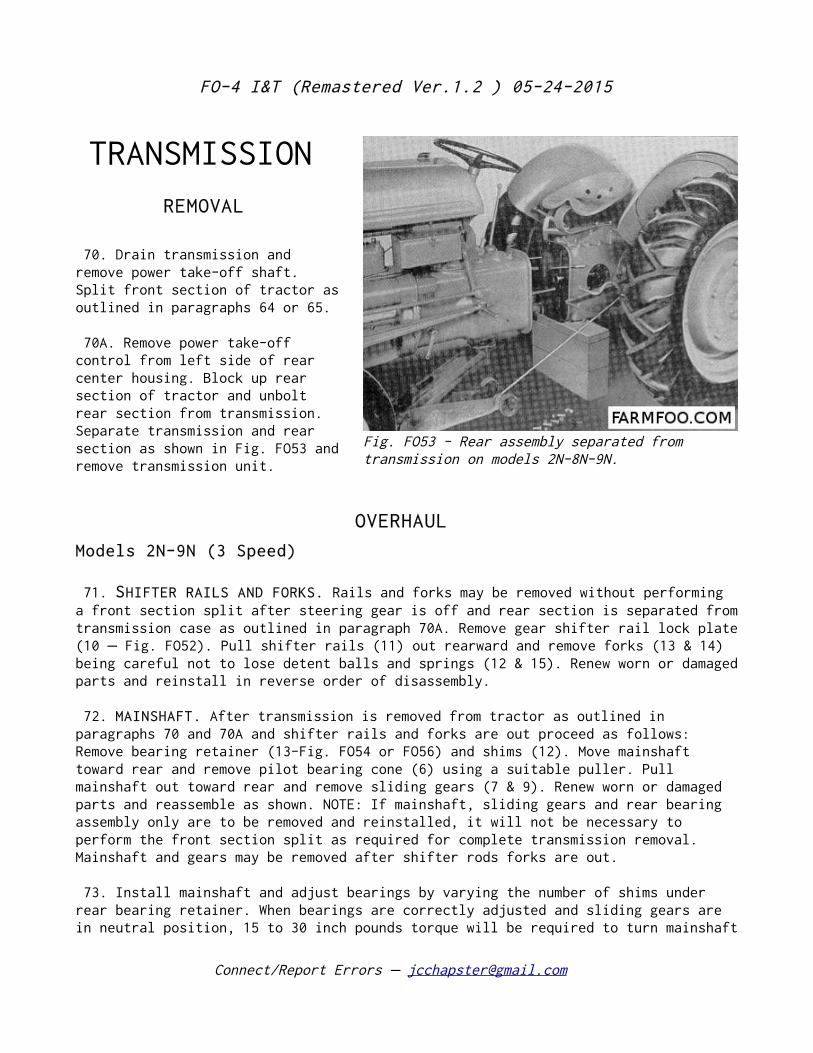
Overhaul 85 85 Adjustment 44 44
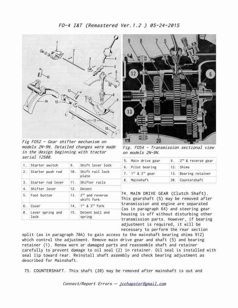
Remove & Reinstall 84 84 Overhaul 45 45
ELECTRICAL HYDRAULIC SYSTEM
Ignition 54-61 54-58 Adjustment 99 101
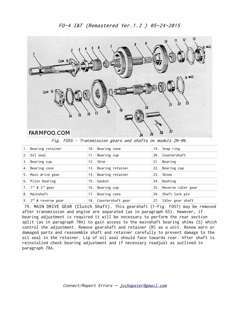
Generator 50 50 Lift Cover 105 109
Generator Regulator 51,52 51,52 Pump Overhaul 124 116
Connect/Report Errors – [email protected]
FO-4 I&T (Remastered Ver.1.2 ) 05-24-2015
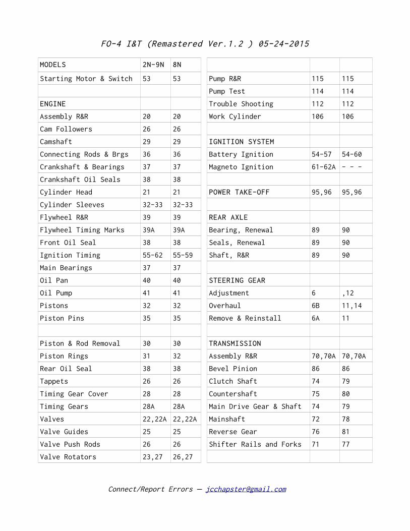
MODELS 2N-9N 8N
Starting Motor & Switch 53 53 Pump R&R 115 115
Pump Test 114 114
ENGINE Trouble Shooting 112 112
Assembly R&R 20 20 Work Cylinder 106 106
Cam Followers 26 26
Camshaft 29 29 IGNITION SYSTEM
Connecting Rods & Brgs 36 36 Battery Ignition 54-57 54-60
Crankshaft & Bearings 37 37 Magneto Ignition 61-62A - - -
Crankshaft Oil Seals 38 38
Cylinder Head 21 21 POWER TAKE-OFF 95,96 95,96
Cylinder Sleeves 32-33 32-33
Flywheel R&R 39 39 REAR AXLE
Flywheel Timing Marks 39A 39A Bearing, Renewal 89 90
Front Oil Seal 38 38 Seals, Renewal 89 90
Ignition Timing 55-62 55-59 Shaft, R&R 89 90
Main Bearings 37 37
Oil Pan 40 40 STEERING GEAR
Oil Pump 41 41 Adjustment 6 ,12
Pistons 32 32 Overhaul 6B 11,14
Piston Pins 35 35 Remove & Reinstall 6A 11
Piston & Rod Removal 30 30 TRANSMISSION
Piston Rings 31 32 Assembly R&R 70,70A 70,70A
Rear Oil Seal 38 38 Bevel Pinion 86 86
Tappets 26 26 Clutch Shaft 74 79
Timing Gear Cover 28 28 Countershaft 75 80
Timing Gears 28A 28A Main Drive Gear & Shaft 74 79
Valves 22,22A 22,22A Mainshaft 72 78
Valve Guides 25 25 Reverse Gear 76 81
Valve Push Rods 26 26 Shifter Rails and Forks 71 77
Valve Rotators 23,27 26,27
Connect/Report Errors – [email protected]
FO-4 I&T (Remastered Ver.1.2 ) 05-24-2015
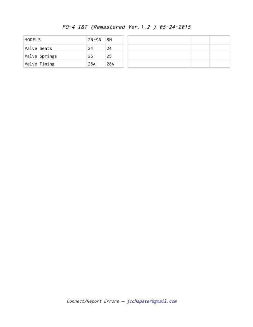
MODELS 2N-9N 8N
Valve Seats 24 24
Valve Springs 25 25
Valve Timing 28A 28A
Connect/Report Errors – [email protected]
FO-4 I&T (Remastered Ver.1.2 ) 05-24-2015
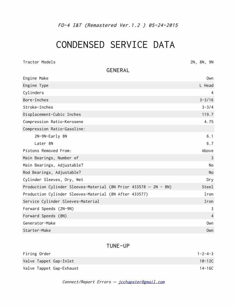
CONDENSED SERVICE DATA
Tractor Models 2N, 8N, 9N
GENERALEngine Make Own
Engine Type L Head
Cylinders 4
Bore-Inches 3-3/16
Stroke-Inches 3-3/4
Displacement-Cubic Inches 119.7
Compression Ratio-Kerosene 4.75
Compression Ratio-Gasoline:
2N-9N-Early 8N 6.1
Later 8N 6.7
Pistons Removed From: Above
Main Bearings, Number of 3
Main Bearings, Adjustable? No
Rod Bearings, Adjustable? No
Cylinder Sleeves, Dry, Wet Dry
Production Cylinder Sleeves-Material (8N Prior 433578 2N - 8N)– Steel
Production Cylinder Sleeves-Material (8N After 433577) Iron
Service Cylinder Sleeves-Material Iron
Forward Speeds (2N-9N) 3
Forward Speeds (8N) 4
Generator-Make Own
Starter-Make Own
TUNE-UPFiring Order 1-2-4-3
Valve Tappet Gap-Inlet 10-12C
Valve Tappet Gap-Exhaust 14-16C
Connect/Report Errors – [email protected]
FO-4 I&T (Remastered Ver.1.2 ) 05-24-2015
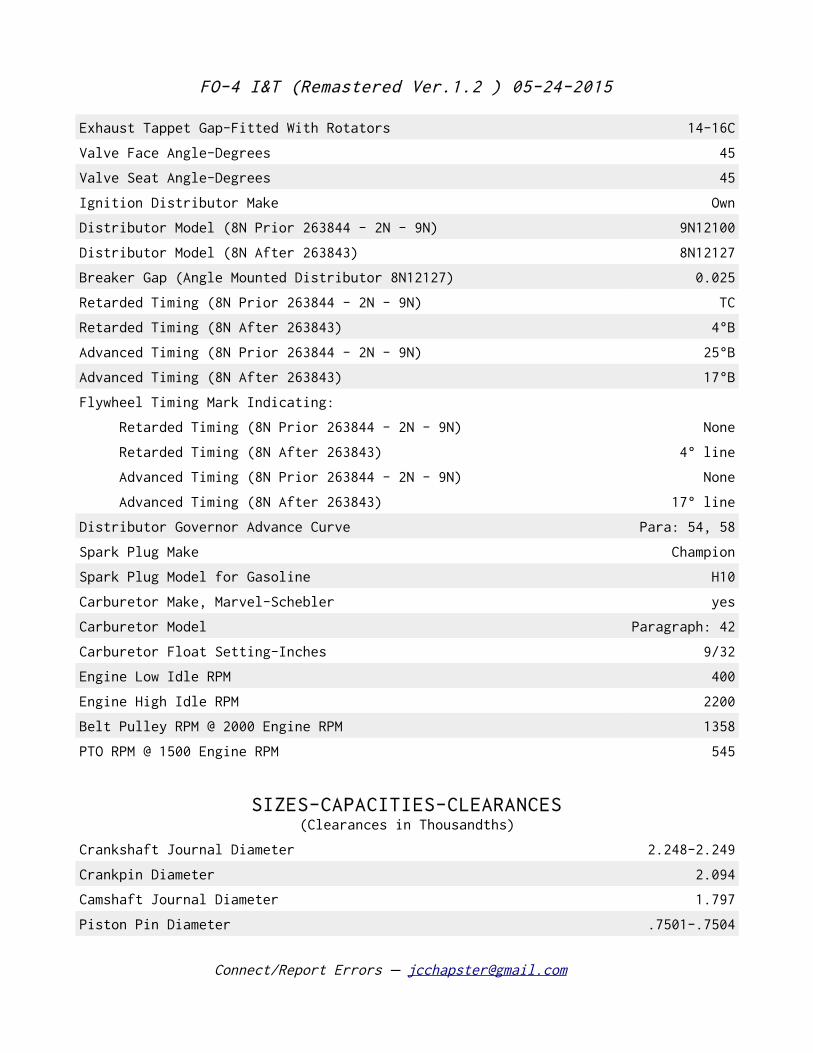
Exhaust Tappet Gap-Fitted With Rotators 14-16C
Valve Face Angle-Degrees 45
Valve Seat Angle-Degrees 45
Ignition Distributor Make Own
Distributor Model (8N Prior 263844 - 2N - 9N) 9N12100
Distributor Model (8N After 263843) 8N12127
Breaker Gap (Angle Mounted Distributor 8N12127) 0.025
Retarded Timing (8N Prior 263844 - 2N - 9N) TC
Retarded Timing (8N After 263843) 4°B
Advanced Timing (8N Prior 263844 - 2N - 9N) 25°B
Advanced Timing (8N After 263843) 17°B
Flywheel Timing Mark Indicating:
Retarded Timing (8N Prior 263844 - 2N - 9N) None
Retarded Timing (8N After 263843) 4° line
Advanced Timing (8N Prior 263844 - 2N - 9N) None
Advanced Timing (8N After 263843) 17° line
Distributor Governor Advance Curve Para: 54, 58
Spark Plug Make Champion
Spark Plug Model for Gasoline H10
Carburetor Make, Marvel-Schebler yes
Carburetor Model Paragraph: 42
Carburetor Float Setting-Inches 9/32
Engine Low Idle RPM 400
Engine High Idle RPM 2200
Belt Pulley RPM @ 2000 Engine RPM 1358
PTO RPM @ 1500 Engine RPM 545
SIZES-CAPACITIES-CLEARANCES(Clearances in Thousandths)
Crankshaft Journal Diameter 2.248-2.249
Crankpin Diameter 2.094
Camshaft Journal Diameter 1.797
Piston Pin Diameter .7501-.7504
Connect/Report Errors – [email protected]
FO-4 I&T (Remastered Ver.1.2 ) 05-24-2015
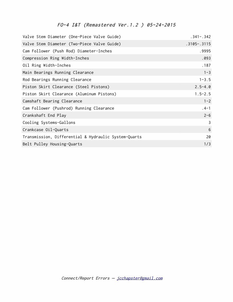
Valve Stem Diameter (One-Piece Valve Guide) .341-.342
Valve Stem Diameter (Two-Piece Valve Guide) .3105-.3115
Cam Follower (Push Rod) Diameter-Inches .9995
Compression Ring Width-Inches .093
Oil Ring Width-Inches .187
Main Bearings Running Clearance 1-3
Rod Bearings Running Clearance 1-3.5
Piston Skirt Clearance (Steel Pistons) 2.5-4.0
Piston Skirt Clearance (Aluminum Pistons) 1.5-2.5
Camshaft Bearing Clearance 1-2
Cam Follower (Pushrod) Running Clearance .4-1
Crankshaft End Play 2-6
Cooling Systems-Gallons 3
Crankcase Oil-Quarts 6
Transmission, Differential & Hydraulic System-Quarts 20
Belt Pulley Housing-Quarts 1/3
Connect/Report Errors – [email protected]
FO-4 I&T (Remastered Ver.1.2 ) 05-24-2015
Connect/Report Errors – [email protected]
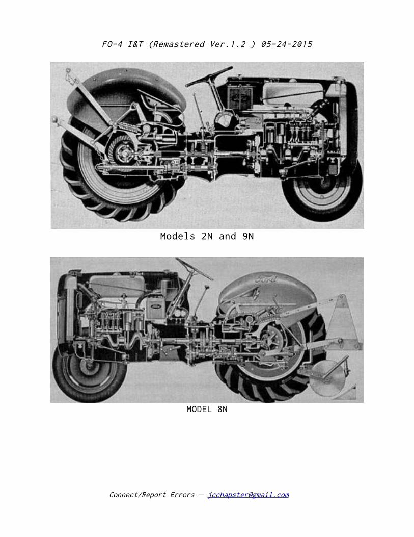
Models 2N and 9N
MODEL 8N
FO-4 I&T (Remastered Ver.1.2 ) 05-24-2015
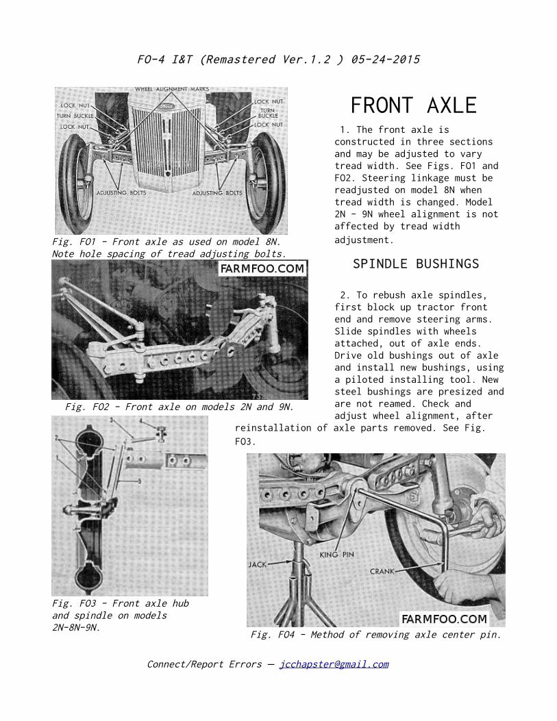
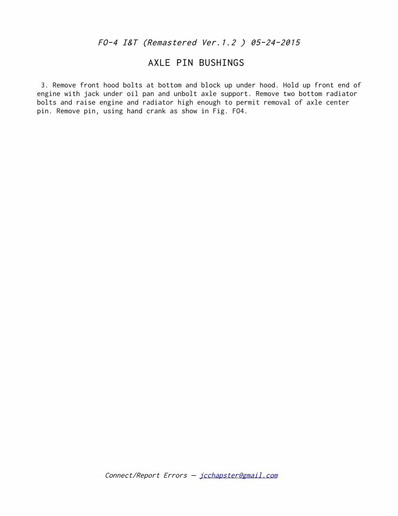
FRONT AXLE 1. The front axle is constructed in three sections and may be adjusted to vary tread width. See Figs. FO1 and FO2. Steering linkage must be readjusted on model 8N when tread width is changed. Model 2N - 9N wheel alignment is not affected by tread width adjustment.
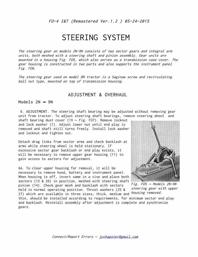
SPINDLE BUSHINGS
2. To rebush axle spindles, first block up tractor front end and remove steering arms. Slide spindles with wheels attached, out of axle ends. Drive old bushings out of axle and install new bushings, using a piloted installing tool. New steel bushings are presized and are not reamed. Check and adjust wheel alignment, after
reinstallation of axle parts removed. See Fig. FO3.
Connect/Report Errors – [email protected]
Fig. FO1 - Front axle as used on model 8N. Note hole spacing of tread adjusting bolts.
Fig. FO2 - Front axle on models 2N and 9N.
Fig. FO3 - Front axle hub and spindle on models 2N-8N-9N.
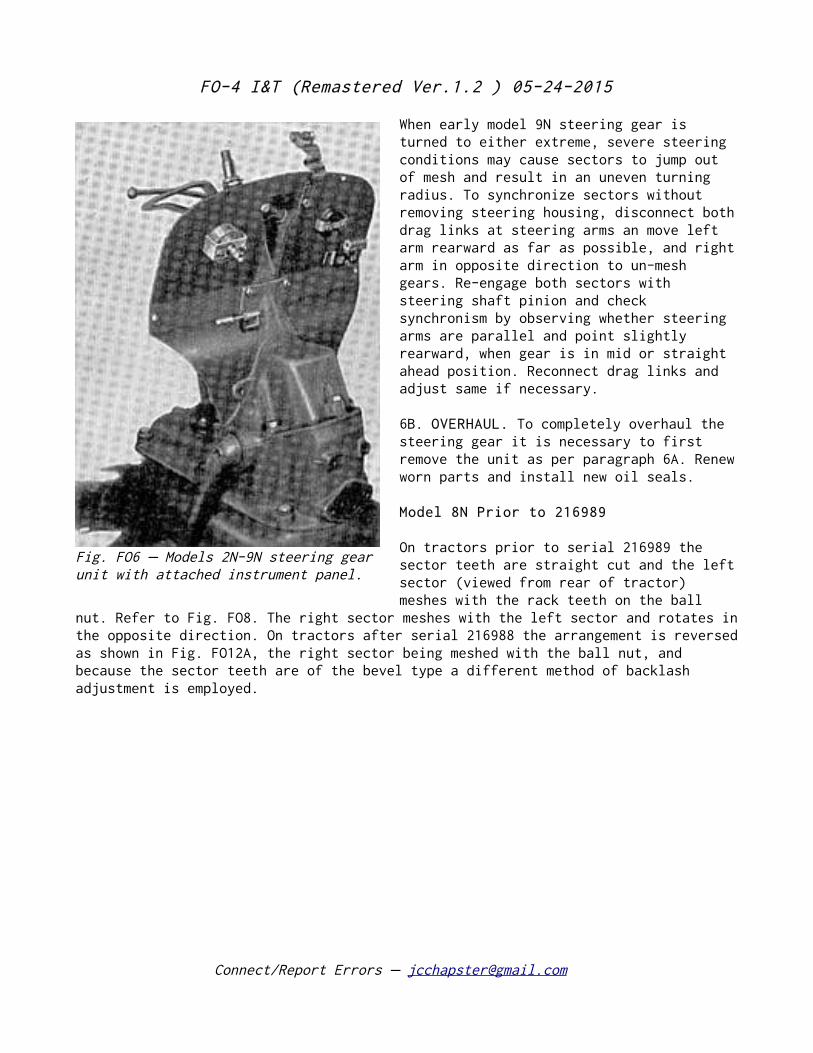
Fig. FO4 - Method of removing axle center pin.
FO-4 I&T (Remastered Ver.1.2 ) 05-24-2015
AXLE PIN BUSHINGS
3. Remove front hood bolts at bottom and block up under hood. Hold up front end of engine with jack under oil pan and unbolt axle support. Remove two bottom radiator bolts and raise engine and radiator high enough to permit removal of axle center pin. Remove pin, using hand crank as show in Fig. FO4.
Connect/Report Errors – [email protected]
FO-4 I&T (Remastered Ver.1.2 ) 05-24-2015
STEERING SYSTEM
The steering gear on models 2N-9N consists of two sector gears and integral arm units, both meshed with a steering shaft and pinion assembly. Gear units are mounted in a housing Fig. FO5, which also serves as a transmission case cover. The gear housing is constructed in two parts and also supports the instrument panel Fig. FO6.
The steering gear used on model 8N tractor is a Saginaw screw and recirculating ball nut type, mounted on top of transmission housing.
ADJUSTMENT & OVERHAUL
Models 2N 9N –
6. ADJUSTMENT. The steering shaft bearing may be adjusted without removing gear unit from tractor. To adjust steering shaft bearings, remove steering wheel and shaft bearing dust cover (19 Fig. FO7). Remove locknut– and lock washer (1). Adjust lower nut until end play is removed and shaft still turns freely. Install lock washer and locknut and tighten nut.
Detach drag links from sector arms and check backlash at arms while steering wheel is held stationary. If excessive sector gear backlash or end play exists, it will be necessary to remove upper gear housing (11) to gain access to sectors for adjustment.
6A. To clear upper housing for removal, it will be necessary to remove hood, battery and instrument panel. When housing is off, invert same in a vise and place both sectors (15 & 26) in position, meshed with steering shaft pinion (14). Check gear mesh and backlash with sectors held in normal operating position. Thrust washers (25 & 27) which are available in three sizes; thick, medium and thin, should be installed according to requirements, for minimum sector end play and backlash. Reinstall assembly after adjustment is complete and synchronize gears.
Connect/Report Errors – [email protected]
Fig. FO5 Models 2N-9N –steering gear with upper housing removed.
FO-4 I&T (Remastered Ver.1.2 ) 05-24-2015
When early model 9N steering gear is turned to either extreme, severe steering conditions may cause sectors to jump out of mesh and result in an uneven turning radius. To synchronize sectors without removing steering housing, disconnect both drag links at steering arms an move left arm rearward as far as possible, and right arm in opposite direction to un-mesh gears. Re-engage both sectors with steering shaft pinion and check synchronism by observing whether steering arms are parallel and point slightly rearward, when gear is in mid or straight ahead position. Reconnect drag links and adjust same if necessary.
6B. OVERHAUL. To completely overhaul the steering gear it is necessary to first remove the unit as per paragraph 6A. Renew worn parts and install new oil seals.
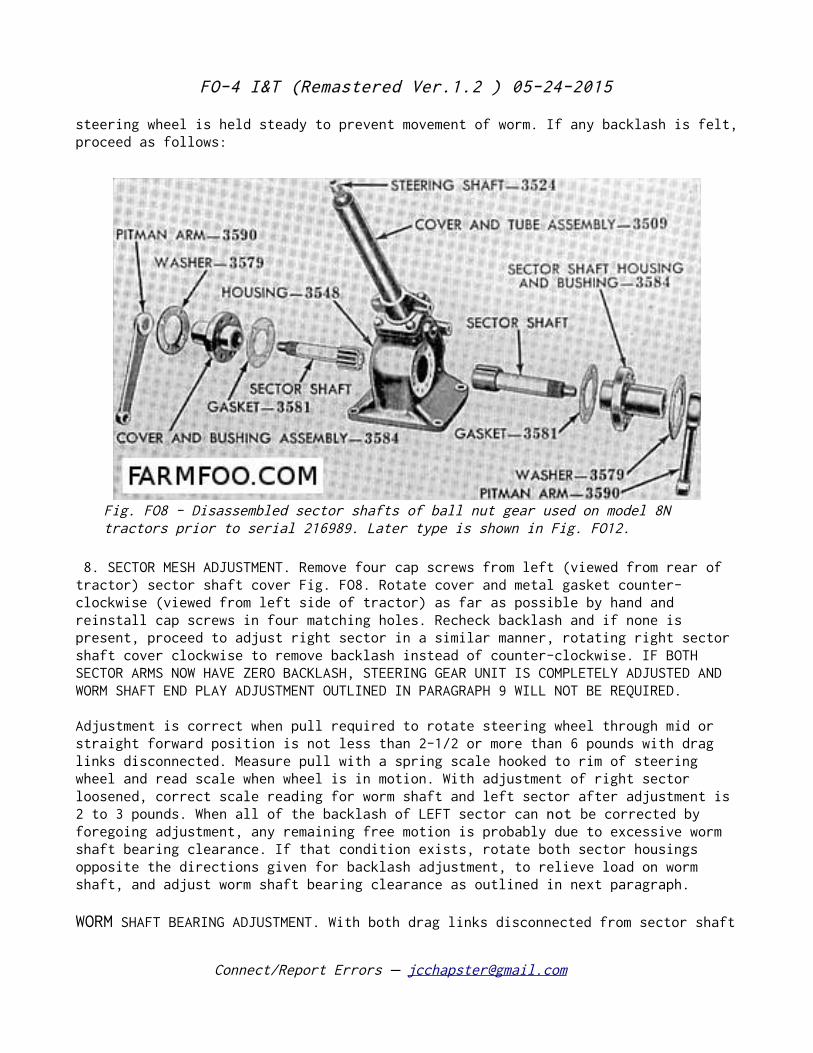
Model 8N Prior to 216989
On tractors prior to serial 216989 the sector teeth are straight cut and the left sector (viewed from rear of tractor) meshes with the rack teeth on the ball
nut. Refer to Fig. FO8. The right sector meshes with the left sector and rotates in the opposite direction. On tractors after serial 216988 the arrangement is reversed as shown in Fig. FO12A, the right sector being meshed with the ball nut, and because the sector teeth are of the bevel type a different method of backlash adjustment is employed.
Connect/Report Errors – [email protected]
Fig. FO6 Models 2N-9N steering gear– unit with attached instrument panel.
FO-4 I&T (Remastered Ver.1.2 ) 05-24-2015
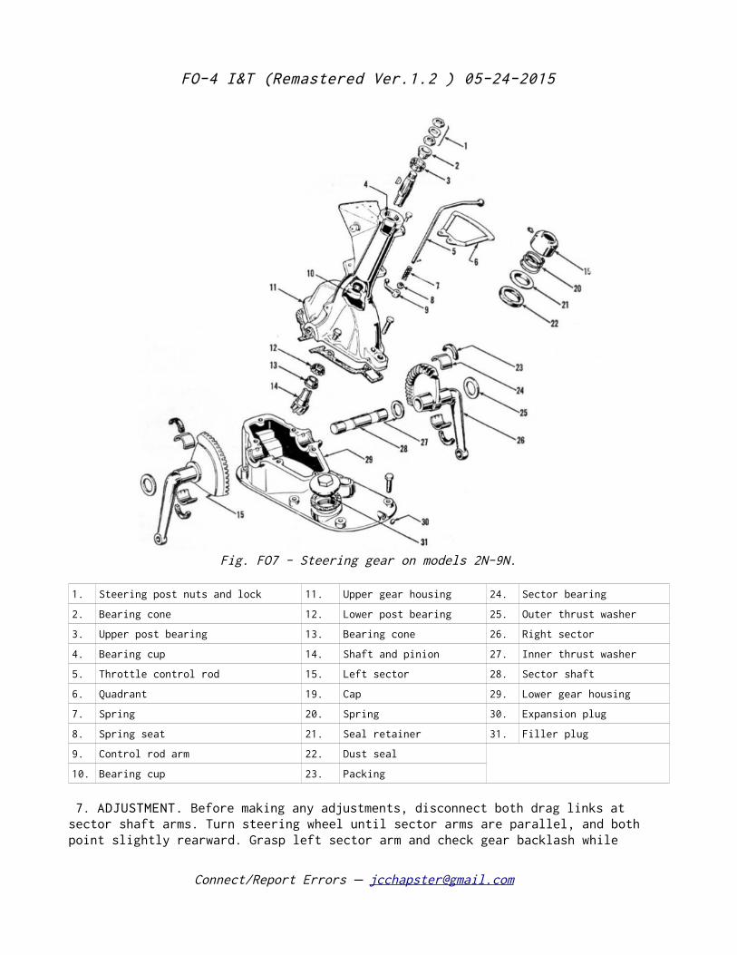
1. Steering post nuts and lock 11. Upper gear housing 24. Sector bearing
2. Bearing cone 12. Lower post bearing 25. Outer thrust washer
3. Upper post bearing 13. Bearing cone 26. Right sector
4. Bearing cup 14. Shaft and pinion 27. Inner thrust washer
5. Throttle control rod 15. Left sector 28. Sector shaft
6. Quadrant 19. Cap 29. Lower gear housing
7. Spring 20. Spring 30. Expansion plug
8. Spring seat 21. Seal retainer 31. Filler plug
9. Control rod arm 22. Dust seal
10. Bearing cup 23. Packing
7. ADJUSTMENT. Before making any adjustments, disconnect both drag links at sector shaft arms. Turn steering wheel until sector arms are parallel, and both point slightly rearward. Grasp left sector arm and check gear backlash while
Connect/Report Errors – [email protected]
Fig. FO7 - Steering gear on models 2N-9N.
FO-4 I&T (Remastered Ver.1.2 ) 05-24-2015
steering wheel is held steady to prevent movement of worm. If any backlash is felt, proceed as follows:
8. SECTOR MESH ADJUSTMENT. Remove four cap screws from left (viewed from rear of tractor) sector shaft cover Fig. FO8. Rotate cover and metal gasket counter-clockwise (viewed from left side of tractor) as far as possible by hand and reinstall cap screws in four matching holes. Recheck backlash and if none is present, proceed to adjust right sector in a similar manner, rotating right sector shaft cover clockwise to remove backlash instead of counter-clockwise. IF BOTH SECTOR ARMS NOW HAVE ZERO BACKLASH, STEERING GEAR UNIT IS COMPLETELY ADJUSTED AND WORM SHAFT END PLAY ADJUSTMENT OUTLINED IN PARAGRAPH 9 WILL NOT BE REQUIRED.
Adjustment is correct when pull required to rotate steering wheel through mid or straight forward position is not less than 2-1/2 or more than 6 pounds with drag links disconnected. Measure pull with a spring scale hooked to rim of steering wheel and read scale when wheel is in motion. With adjustment of right sector loosened, correct scale reading for worm shaft and left sector after adjustment is 2 to 3 pounds. When all of the backlash of LEFT sector can not be corrected by foregoing adjustment, any remaining free motion is probably due to excessive worm shaft bearing clearance. If that condition exists, rotate both sector housings opposite the directions given for backlash adjustment, to relieve load on worm shaft, and adjust worm shaft bearing clearance as outlined in next paragraph.
WORM SHAFT BEARING ADJUSTMENT. With both drag links disconnected from sector shaft
Connect/Report Errors – [email protected]
Fig. FO8 - Disassembled sector shafts of ball nut gear used on model 8N tractors prior to serial 216989. Later type is shown in Fig. FO12.
FO-4 I&T (Remastered Ver.1.2 ) 05-24-2015
arms, and with both sector adjustments loosened, check worm shaft bearing adjustment by pulling up and pushing down on steering wheel. If looseness is present, adjust bearings to a slight pre-load by removing a shim or shims from top face of gear housing, after first removing steering gear cover and tube assembly Fig. FO10. To clear gear assembly for removal, it will be necessary to remove hood, battery and instrument panel.
Bearing adjustment is correct, when pull required to rotate steering wheel through center or straight forward position is 1-1/2 pounds with drag links disconnected and sector mesh adjustments loosened. Measure pull with a spring scale hooked to rim of wheel and take the reading while wheel is in motion.
After completing worm shaft bearing adjustment, readjust backlash of both sectors as outlined in paragraphs 7 and 8.
11. OVERHAUL. Hood, battery and instrument panel must be removed before steering gear unit can be removed. After unit is cleared for removal, disconnect both drag links at steering gear arms, unbolt steering gear unit from transmission housing and lift unit off of tractor.
11A. Pull both steering gear arms off sector shafts and unscrew cap screws holding sector shaft housings to gear case. Remove both sector
gears and covers from sides of gear case Fig. FO8. To facilitate removal of –these sub assemblies, turn them clockwise and they are withdrawn. Remove shaft tube flange cap screws and lift assembly off of gear case. CAUTION: Do not turn worm shaft if nut is near either end of worm as ball retainers may be damaged.
New sector shaft housing inner bushings are pressed into housing 1/8 inch below face of hub . Outer bushings are installed flush or slightly below bottom of dust seal counterbores. Bushings should be align reamed to 1.125 1.126. –
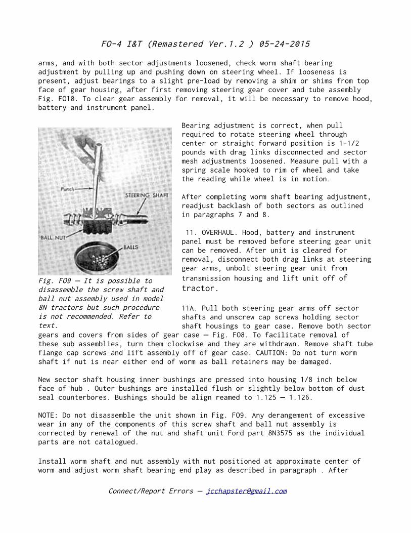
NOTE: Do not disassemble the unit shown in Fig. FO9. Any derangement of excessive wear in any of the components of this screw shaft and ball nut assembly is corrected by renewal of the nut and shaft unit Ford part 8N3575 as the individual parts are not catalogued.
Install worm shaft and nut assembly with nut positioned at approximate center of worm and adjust worm shaft bearing end play as described in paragraph . After
Connect/Report Errors – [email protected]
Fig. FO9 It is possible to –disassemble the screw shaft and ball nut assembly used in model 8N tractors but such procedure is not recommended. Refer to text.
FO-4 I&T (Remastered Ver.1.2 ) 05-24-2015
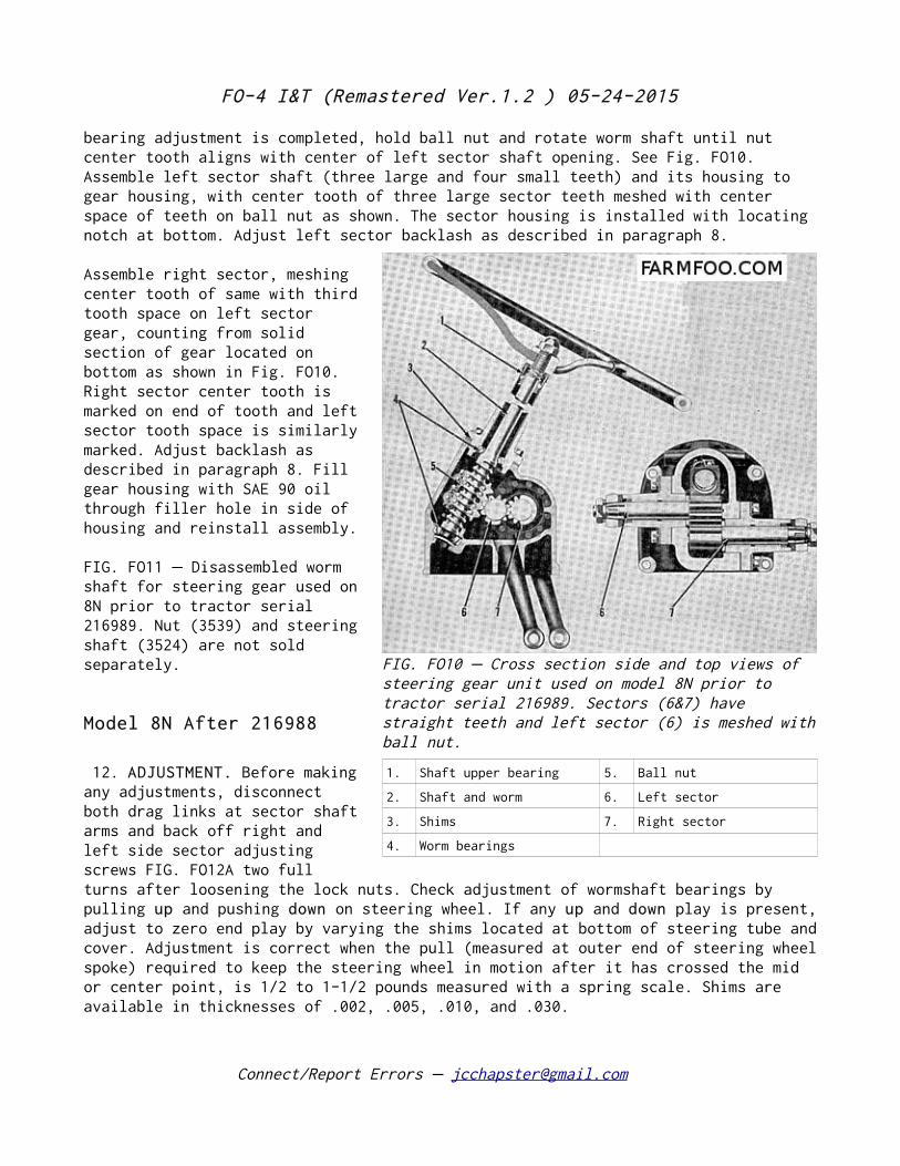
bearing adjustment is completed, hold ball nut and rotate worm shaft until nut center tooth aligns with center of left sector shaft opening. See Fig. FO10. Assemble left sector shaft (three large and four small teeth) and its housing to gear housing, with center tooth of three large sector teeth meshed with center space of teeth on ball nut as shown. The sector housing is installed with locating notch at bottom. Adjust left sector backlash as described in paragraph 8.
Assemble right sector, meshing center tooth of same with third tooth space on left sector gear, counting from solid section of gear located on bottom as shown in Fig. FO10. Right sector center tooth is marked on end of tooth and left sector tooth space is similarly marked. Adjust backlash as described in paragraph 8. Fill gear housing with SAE 90 oil through filler hole in side of housing and reinstall assembly.
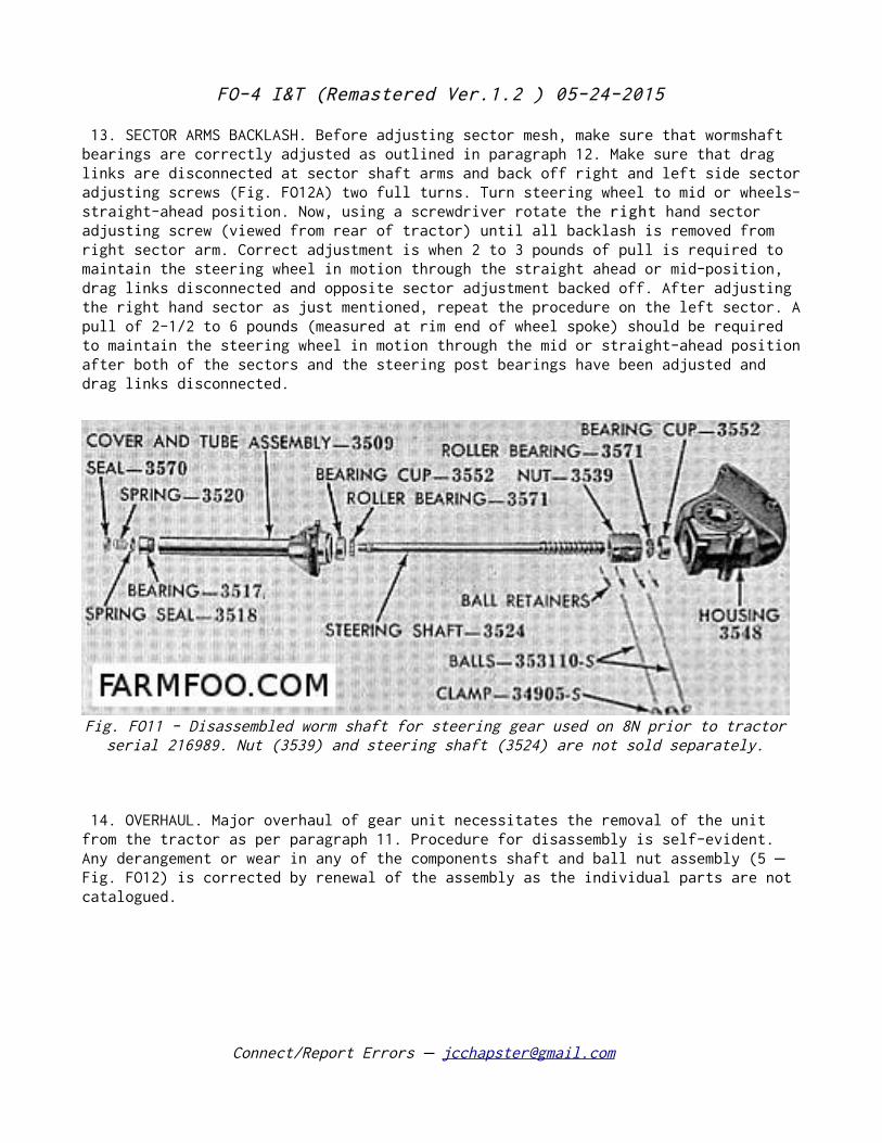
FIG. FO11 Disassembled worm– shaft for steering gear used on 8N prior to tractor serial 216989. Nut (3539) and steering shaft (3524) are not sold separately.
Model 8N After 216988
12. ADJUSTMENT. Before making any adjustments, disconnect both drag links at sector shaft arms and back off right and left side sector adjusting screws FIG. FO12A two full turns after loosening the lock nuts. Check adjustment of wormshaft bearings by pulling up and pushing down on steering wheel. If any up and down play is present, adjust to zero end play by varying the shims located at bottom of steering tube and cover. Adjustment is correct when the pull (measured at outer end of steering wheel spoke) required to keep the steering wheel in motion after it has crossed the mid or center point, is 1/2 to 1-1/2 pounds measured with a spring scale. Shims are available in thicknesses of .002, .005, .010, and .030.
Connect/Report Errors – [email protected]
FIG. FO10 Cross section side and top views of –steering gear unit used on model 8N prior to tractor serial 216989. Sectors (6&7) have straight teeth and left sector (6) is meshed with ball nut.
1. Shaft upper bearing 5. Ball nut
2. Shaft and worm 6. Left sector
3. Shims 7. Right sector
4. Worm bearings
FO-4 I&T (Remastered Ver.1.2 ) 05-24-2015
13. SECTOR ARMS BACKLASH. Before adjusting sector mesh, make sure that wormshaft bearings are correctly adjusted as outlined in paragraph 12. Make sure that drag links are disconnected at sector shaft arms and back off right and left side sector adjusting screws (Fig. FO12A) two full turns. Turn steering wheel to mid or wheels-straight-ahead position. Now, using a screwdriver rotate the right hand sector adjusting screw (viewed from rear of tractor) until all backlash is removed from right sector arm. Correct adjustment is when 2 to 3 pounds of pull is required to maintain the steering wheel in motion through the straight ahead or mid-position, drag links disconnected and opposite sector adjustment backed off. After adjusting the right hand sector as just mentioned, repeat the procedure on the left sector. A pull of 2-1/2 to 6 pounds (measured at rim end of wheel spoke) should be required to maintain the steering wheel in motion through the mid or straight-ahead position after both of the sectors and the steering post bearings have been adjusted and drag links disconnected.
14. OVERHAUL. Major overhaul of gear unit necessitates the removal of the unit from the tractor as per paragraph 11. Procedure for disassembly is self-evident. Any derangement or wear in any of the components shaft and ball nut assembly (5 –Fig. FO12) is corrected by renewal of the assembly as the individual parts are not catalogued.
Connect/Report Errors – [email protected]
Fig. FO11 - Disassembled worm shaft for steering gear used on 8N prior to tractor serial 216989. Nut (3539) and steering shaft (3524) are not sold separately.
FO-4 I&T (Remastered Ver.1.2 ) 05-24-2015
Select and insert shims (9 Fig.– FO12) between underside of inner head of lash adjuster screws (2) and slot in sectors to provide zero to .002 end play of adjuster screws in sectors. Shims (9) are available in thicknesses of .063, .065, .067 and .069.
TOE-IN ADJUSTMENT 15. Toe-in is adjusted by varying the length of the drag links. Models 2N 9N drag link is adjusted by– disconnecting link front end, loosening lock clamp and screwing link end in or out as required. Model 8N drag links are provided with turn-buckle type adjustment and do not require disconnection. The wheels may be aligned approximately by adjusting drag links until spindle arms are centered over the radius rod to axle member bolts or the reference marks. Correct toe-in is 0 to 1/4 inch.
Connect/Report Errors – [email protected]
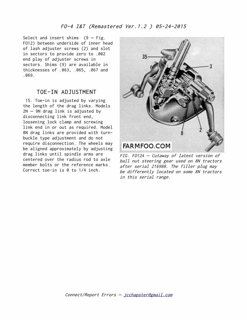
FIG. FO12A Cutaway of latest version of –ball nut steering gear used on 8N tractors after serial 216988. The filler plug may be differently located on some 8N tractors in this serial range.
FO-4 I&T (Remastered Ver.1.2 ) 05-24-2015
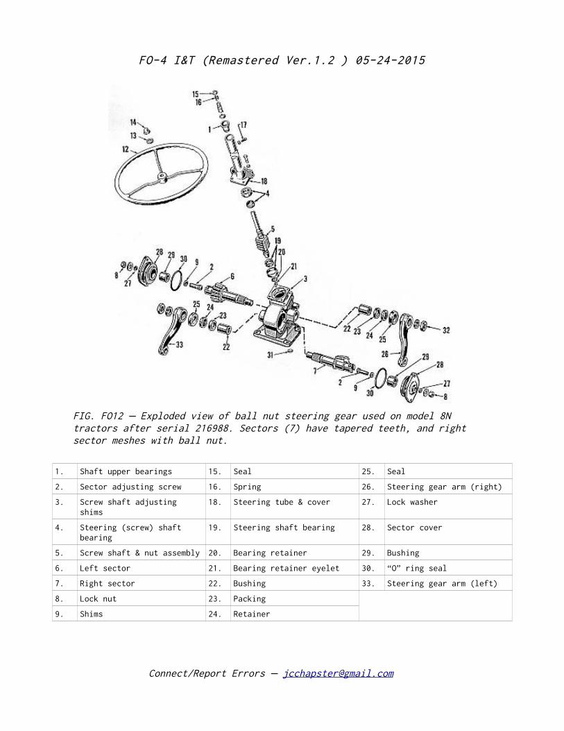
1. Shaft upper bearings 15. Seal 25. Seal
2. Sector adjusting screw 16. Spring 26. Steering gear arm (right)
3. Screw shaft adjusting shims
18. Steering tube & cover 27. Lock washer
4. Steering (screw) shaft bearing
19. Steering shaft bearing 28. Sector cover
5. Screw shaft & nut assembly 20. Bearing retainer 29. Bushing
6. Left sector 21. Bearing retainer eyelet 30. “O” ring seal
7. Right sector 22. Bushing 33. Steering gear arm (left)
8. Lock nut 23. Packing
9. Shims 24. Retainer
Connect/Report Errors – [email protected]
FIG. FO12 Exploded view of ball nut steering gear used on model 8N –tractors after serial 216988. Sectors (7) have tapered teeth, and right sector meshes with ball nut.
FO-4 I&T (Remastered Ver.1.2 ) 05-24-2015
ENGINE AND COMPONENTS
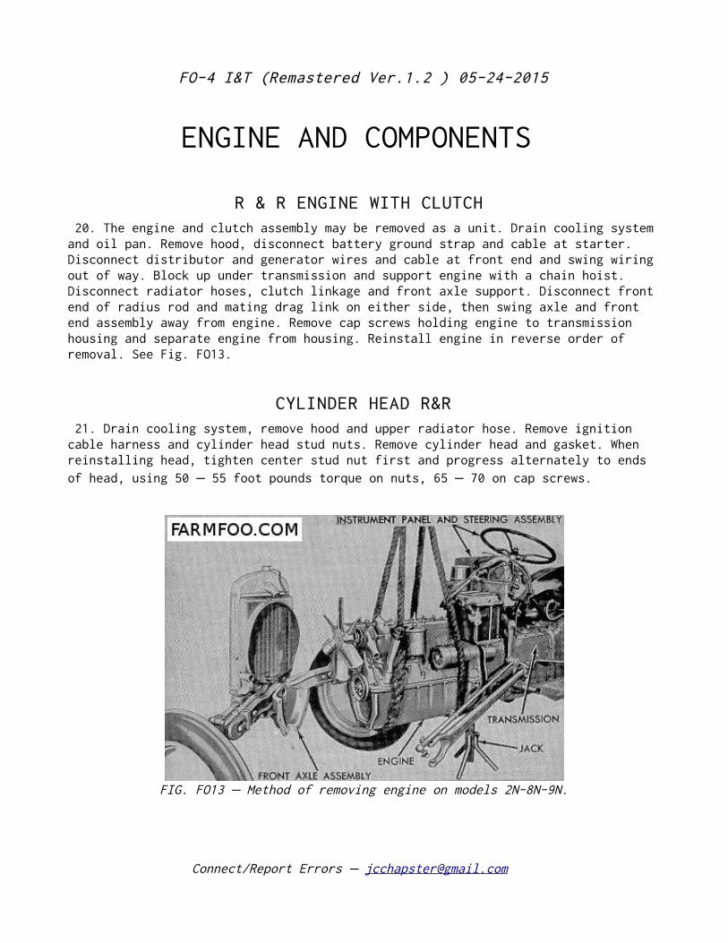
R & R ENGINE WITH CLUTCH 20. The engine and clutch assembly may be removed as a unit. Drain cooling system and oil pan. Remove hood, disconnect battery ground strap and cable at starter. Disconnect distributor and generator wires and cable at front end and swing wiring out of way. Block up under transmission and support engine with a chain hoist. Disconnect radiator hoses, clutch linkage and front axle support. Disconnect front end of radius rod and mating drag link on either side, then swing axle and front end assembly away from engine. Remove cap screws holding engine to transmission housing and separate engine from housing. Reinstall engine in reverse order of removal. See Fig. FO13.
CYLINDER HEAD R&R 21. Drain cooling system, remove hood and upper radiator hose. Remove ignition cable harness and cylinder head stud nuts. Remove cylinder head and gasket. When reinstalling head, tighten center stud nut first and progress alternately to ends of head, using 50 55 foot pounds torque on nuts, 65 70 on cap screws.– –
Connect/Report Errors – [email protected]
FIG. FO13 Method of removing engine on models 2N-8N-9N.–
FO-4 I&T (Remastered Ver.1.2 ) 05-24-2015
VALVES
Inlet & Plain Exhaust
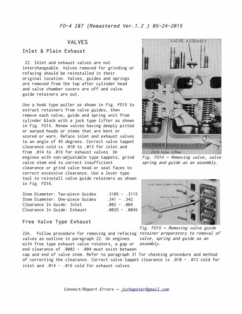
22. Inlet and exhaust valves are not interchangeable. Valves removed for grinding or refacing should be reinstalled in their original location. Valves, guides and springs are removed from the top after cylinder head and valve chamber covers are off and valve guide retainers are out.
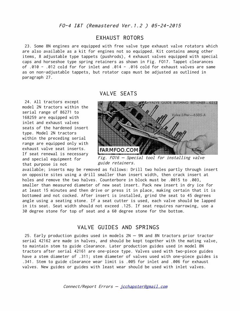
Use a hook type puller as shown in Fig. FO15 to extract retainers from valve guides, then remove each valve, guide and spring unit from cylinder block with a jack type lifter as shown in Fig. FO14. Renew valves having deeply pitted or warped heads or stems that are bent or scored or worn. Reface inlet and exhaust valves to an angle of 45 degrees. Correct valve tappet clearance cold is .010 to .013 for inlet and from .014 to .016 for exhaust valves. On engines with non-adjustable type tappets, grind valve stem end to correct insufficient clearance or grind valve head or seat faces to correct excessive clearance. Use a lever type tool to reinstall valve guide retainers as shown in Fig. FO16.
Stem Diameter: Two-piece Guides .3105 - .3115 Stem Diameter: One-piece Guides .341 - .342 Clearance In Guide: Inlet .002 - .004 Clearance In Guide: Exhaust .0025 - .0045
Free Valve Type Exhaust
22A. Follow procedure for removing and refacing valves as outline in paragraph 22. On engines with free type exhaust valve rotators, a gap or end clearance of .0002 - .004 must exist between cap and end of valve stem. Refer to paragraph 31 for checking procedure and method of correcting the clearance. Correct valve tappet clearance is .010 - .012 cold for inlet and .014 - .016 cold for exhaust valves.
Connect/Report Errors – [email protected]
Fig. FO14 Removing valve, valve– spring and guide as an assembly.
Fig. FO15 Removing valve guide –retainer preparatory to removal of valve, spring and guide as an assembly.
FO-4 I&T (Remastered Ver.1.2 ) 05-24-2015
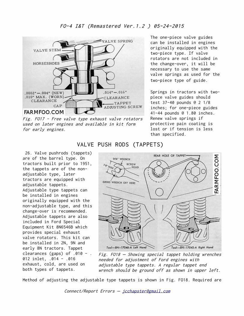
EXHAUST ROTORS 23. Some 8N engines are equipped with free valve type exhaust valve rotators which are also available as a kit for engines not so equipped. Kit contains among other items, 8 adjustable type tappets (pushrods), 4 exhaust valves equipped with special caps and horseshoe type spring retainers as shown in Fig. FO17. Tappet clearances of .010 - .012 cold for for inlet and .014 - .016 cold for exhaust valves are same as on non-adjustable tappets, but rotator caps must be adjusted as outlined in paragraph 27.
VALVE SEATS 24. All tractors except model 2N tractors within the serial range of 86271 to 168259 are equipped with inlet and exhaust valves seats of the hardened insert type. Model 2N tractors within the preceding serial range are equipped only with exhaust valve seat inserts. If seat renewal is necessary and special equipment for that purpose is not available; inserts may be removed as follows: Drill two holes partly through insert on opposite sites using a drill smaller than insert width, then crack insert at holes and remove the two halves. Counterbore in block must be .0015 to .003, smaller than measured diameter of new seat insert. Pack new insert in dry ice for at least 15 minutes and then drive or press it in place, making certain that it is bottomed and not cocked. After insert is installed, grind the seat to 45 degrees angle using a seating stone. If a seat cutter is used, each valve should be lapped in its seat. Seat width should not exceed .125. If seat requires narrowing, use a 30 degree stone for top of seat and a 60 degree stone for the bottom.
VALVE GUIDES AND SPRINGS 25. Early production guides used in models 2N 9N and 8N tractors prior tractor –serial 42162 are made in halves, and should be kept together with the mating valve, to maintain stem to guide clearance. Later production guides used in model 8N tractors after serial 42161 are one-piece type. Valves used with two-piece guides have a stem diameter of .311; stem diameter of valves used with one-piece guides is .341. Stem to guide clearance wear limit is .005 for inlet and .006 for exhaust valves. New guides or guides with least wear should be used with inlet valves.
Connect/Report Errors – [email protected]
Fig. FO16 Special tool for installing valve –guide retainers.
FO-4 I&T (Remastered Ver.1.2 ) 05-24-2015
The one-piece valve guides can be installed in engines originally equipped with the two-piece type. If valve rotators are not included in the change-over, it will be necessary to use the same valve springs as used for the two-piece type of guide.
Springs in tractors with two-piece valve guides should test 37-40 pounds @ 2 1/8 inches; for one-piece guides 41-44 pounds @ 1.80 inches. Renew valve springs if protective pain coating is lost or if tension is less than specified.
VALVE PUSH RODS (TAPPETS) 26. Valve pushrods (tappets) are of the barrel type. On tractors built prior to 1951, the tappets are of the non-adjustable type, later tractors are equipped with adjustable tappets. Adjustable type tappets can be installed in engines originally equipped with the non-adjustable type, and this change-over is recommended. Adjustable tappets are also included in Ford Special Equipment Kit 8N6546B which provides special exhaust valve rotators. This kit can be installed in 2N, 9N and early 8N tractors. Tappet clearances (gaps) of .010 - .012 inlet, .014 - .016 exhaust, cold, are used on both types of tappets.
Method of adjusting the adjustable type tappets is shown in Fig. FO18. Required are
Connect/Report Errors – [email protected]
Fig. FO17 - Free valve type exhaust valve rotators used on later engines and available in kit form for early engines.
Fig. FO18 Showing special tappet holding wrenches– needed for adjustment of Ford engines with adjustable type tappets. A regular tappet end wrench should be ground off as shown in upper left.
FO-4 I&T (Remastered Ver.1.2 ) 05-24-2015
a left hand tappet-holding wrench Ford 8N17046A, right hand tappet-holding wrench 8N17045A and a conventional tappet wrench ground off so that it does not extend past the adjusting screw.
27. FREE TYPE EXHAUST VALVES. On engines with free type exhaust valve rotators (Fig. FO17) a gap or end clearance of .0002 to .004 must exist between cap and end of valve stem as shown. One method of checking this gap with valve installed in engine is show in Fig. FO19. Valve must be off its seat when making this check. If clearance is more than .004, reduce the length of cap by lapping open end of same on emery cloth laid on a flat, smooth surface. If clearance is less than .002 install new valve keys or, if keys are not work, grind end of valve stem until specified clearance is obtained. For additional data on various types of valve rotators, refer to STANDARD UNITS manual.
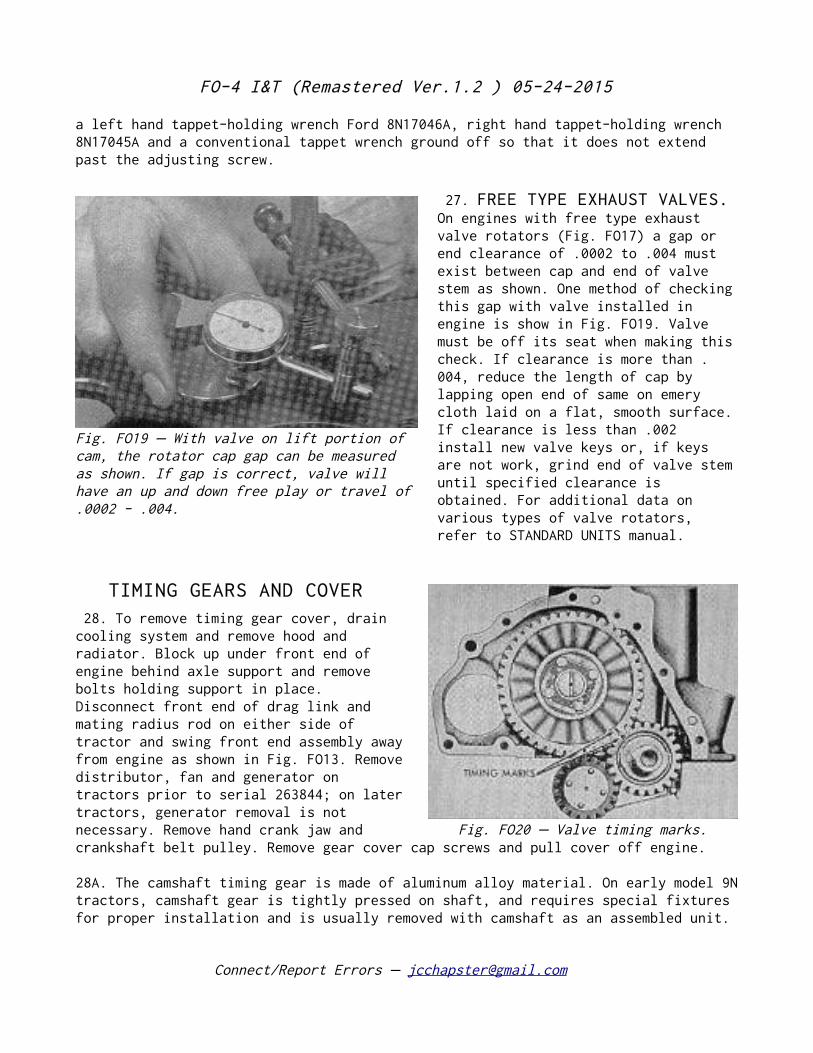
TIMING GEARS AND COVER 28. To remove timing gear cover, drain cooling system and remove hood and radiator. Block up under front end of engine behind axle support and remove bolts holding support in place. Disconnect front end of drag link and mating radius rod on either side of tractor and swing front end assembly away from engine as shown in Fig. FO13. Remove distributor, fan and generator on tractors prior to serial 263844; on later tractors, generator removal is not necessary. Remove hand crank jaw and crankshaft belt pulley. Remove gear cover cap screws and pull cover off engine.
28A. The camshaft timing gear is made of aluminum alloy material. On early model 9N tractors, camshaft gear is tightly pressed on shaft, and requires special fixtures for proper installation and is usually removed with camshaft as an assembled unit.
Connect/Report Errors – [email protected]
Fig. FO19 With valve on lift portion of –cam, the rotator cap gap can be measured as shown. If gap is correct, valve will have an up and down free play or travel of .0002 - .004.
Fig. FO20 Valve timing marks.–
FO-4 I&T (Remastered Ver.1.2 ) 05-24-2015
On later tractors the gear is bolted on and may be removed without disturbing camshaft. Cam gears are available in the bolted-on type in two oversizes: .006 and .012.
Camshaft gears of the pressed-on type are supplied for service. However, service camshafts for this type of gear installation are discontinued, and only camshafts of the bolted-on gear type are supplied.
Renewal of crankshaft gear requires use of puller and removal of front main bearing cap and oil pump assembly. When reinstalling camshaft gear, mesh timing marks on gears as show in Fig. FO20 and use extreme care so as not to injure or scrape the comparatively soft tooth faces of the camshaft gear.
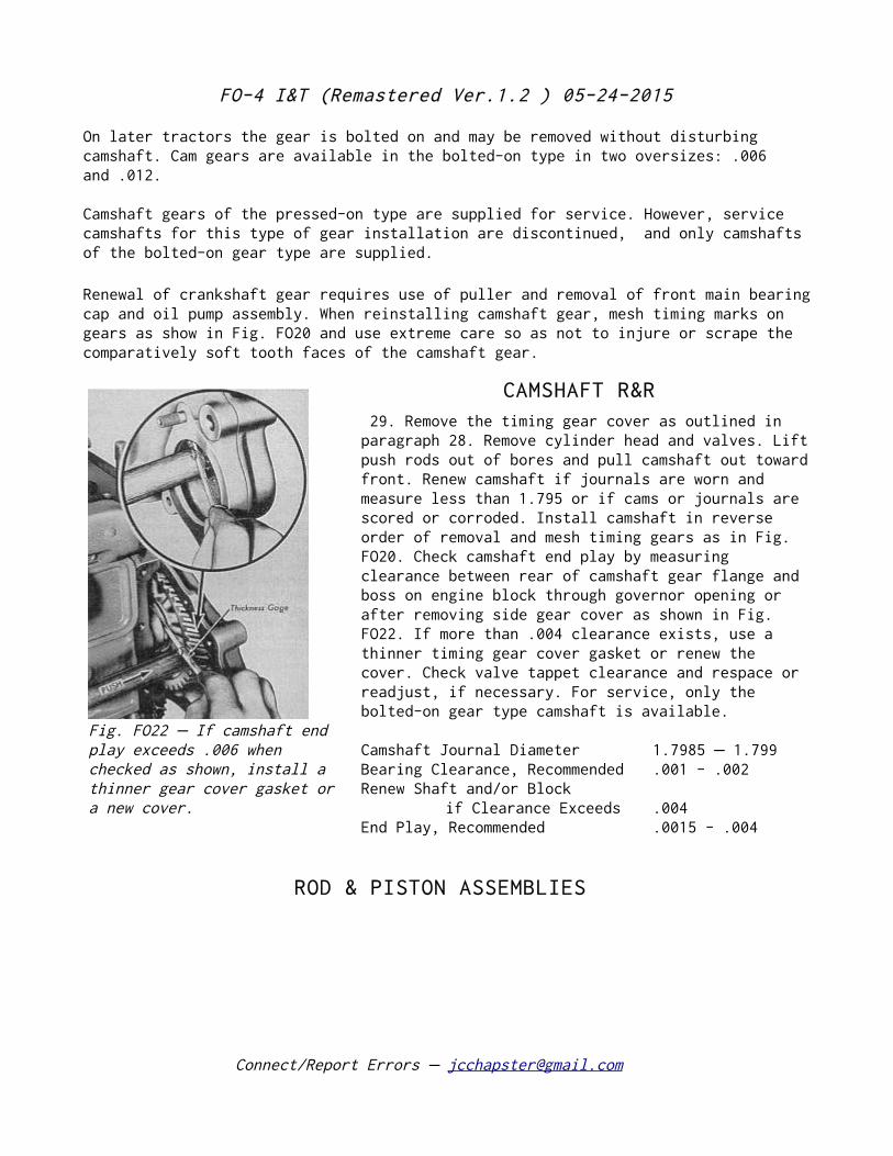
CAMSHAFT R&R 29. Remove the timing gear cover as outlined in paragraph 28. Remove cylinder head and valves. Lift push rods out of bores and pull camshaft out toward front. Renew camshaft if journals are worn and measure less than 1.795 or if cams or journals are scored or corroded. Install camshaft in reverse order of removal and mesh timing gears as in Fig. FO20. Check camshaft end play by measuring clearance between rear of camshaft gear flange and boss on engine block through governor opening or after removing side gear cover as shown in Fig. FO22. If more than .004 clearance exists, use a thinner timing gear cover gasket or renew the cover. Check valve tappet clearance and respace or readjust, if necessary. For service, only the bolted-on gear type camshaft is available.
Camshaft Journal Diameter 1.7985 1.799 –Bearing Clearance, Recommended .001 - .002 Renew Shaft and/or Block
if Clearance Exceeds .004 End Play, Recommended .0015 - .004
ROD & PISTON ASSEMBLIES
Connect/Report Errors – [email protected]
Fig. FO22 If camshaft end –play exceeds .006 when checked as shown, install a thinner gear cover gasket or a new cover.
FO-4 I&T (Remastered Ver.1.2 ) 05-24-2015
30. Piston and connecting rod assemblies may be removed from the top, after cylinder head and oil pan are off.
Identify unmarked pistons and rods to correspond with cylinders in which they are installed, reinstalling them in same relative position occupied before removal. Install connecting rods with numbered sides toward camshaft and oil squirt holes to the front or rear. On aluminum pistons, assemble pistons to rods so that notch in piston head is toward timing gear end of engine. Tighten connecting rod nuts to 35 40 foot– pounds.
NOTE: Pistons must be removed carefully to prevent breaking ring groove lands when passing ridge which may be present at top of cylinder.
PISTON RINGS 31. Two compression rings and one oil control ring are used on each piston., Ring gap should measure .010 to .017. Top compression ring side clearance should be within the limits .0015 - .003; second ring clearance should be within limits .001 - .0025. New rings are marked to indicate top side and are installed accordingly. Counterbore must be up on top ring. Second ring is provided with an expander.
SLEEVES & PISTONS Hardened steel sleeves were used in production up to tractor serial 8N 433578; –iron sleeves in later production tractors. Engines with iron sleeves can be identified externally by the diamond before and after the serial number, which replaces the star used on engines with steel sleeves. The outside diameter of iron sleeves in approximately .098 larger than steel sleeves, hence, the diameter of the bores in the cylinder block equipped with iron sleeves is about .098 larger than the block bore of engines equipped with steel sleeves. Iron sleeves are also flanged at the top. Installation of iron sleeves in a block originally equipped with steel sleeves necessitates the reboring and counter-boring of the cylinder block as outlined in paragraph 33. Bare pistons are not catalogued but pistons with fitted pins and pin retainers are furnished standard and in oversizes of.020, .030 and .040.
Connect/Report Errors – [email protected]
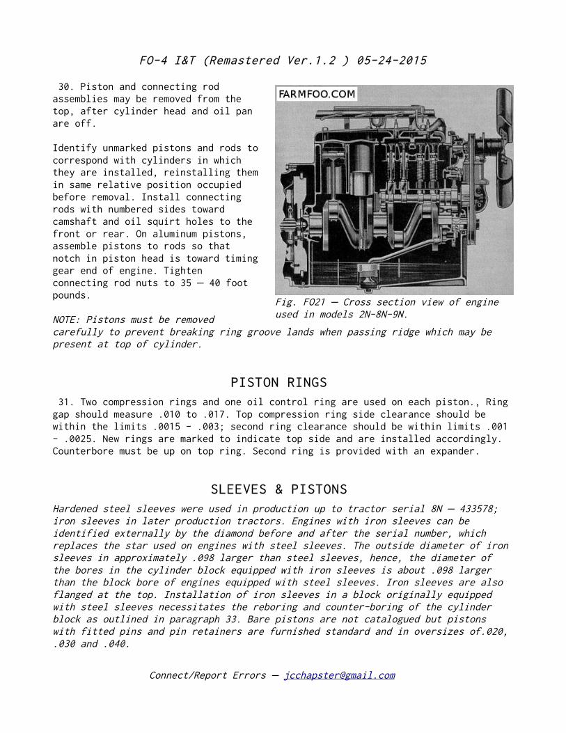
Fig. FO21 Cross section view of engine –used in models 2N-8N-9N.
FO-4 I&T (Remastered Ver.1.2 ) 05-24-2015
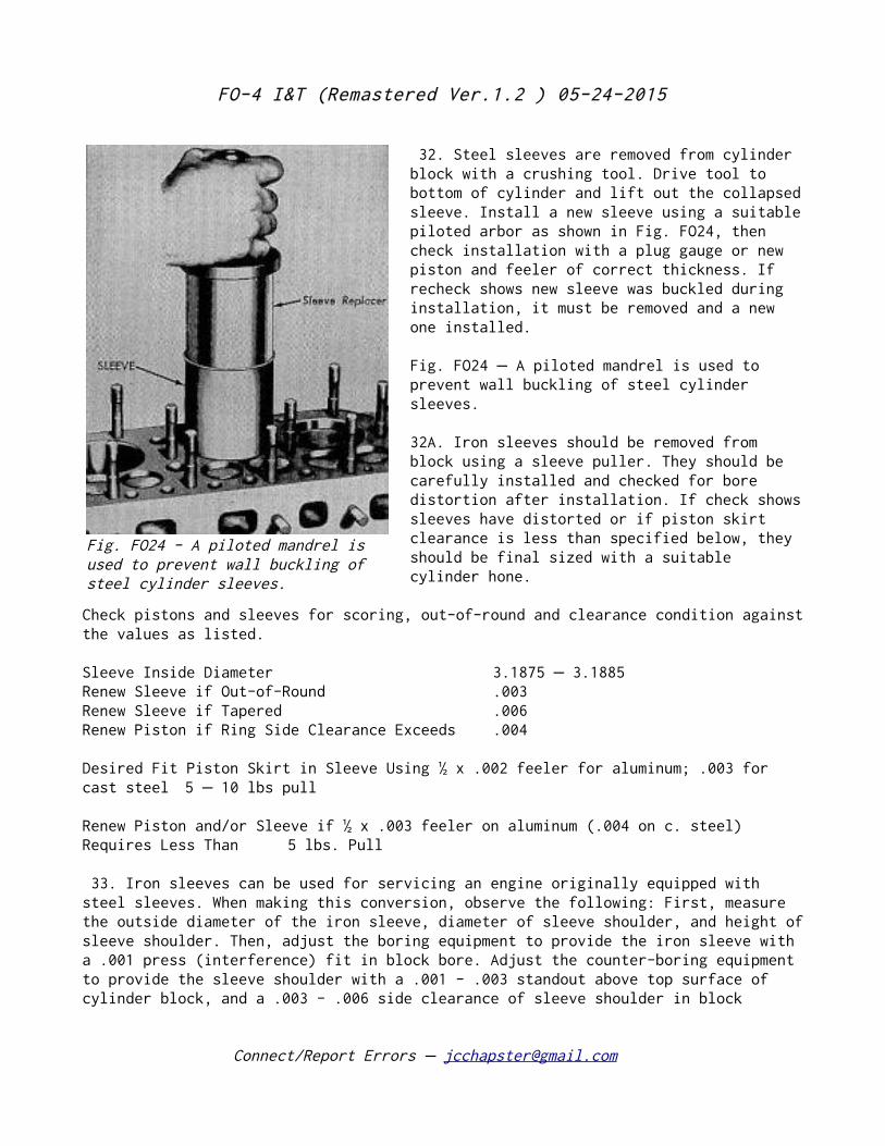
32. Steel sleeves are removed from cylinder block with a crushing tool. Drive tool to bottom of cylinder and lift out the collapsed sleeve. Install a new sleeve using a suitable piloted arbor as shown in Fig. FO24, then check installation with a plug gauge or new piston and feeler of correct thickness. If recheck shows new sleeve was buckled during installation, it must be removed and a new one installed.
Fig. FO24 A piloted mandrel is used to –prevent wall buckling of steel cylinder sleeves.
32A. Iron sleeves should be removed from block using a sleeve puller. They should be carefully installed and checked for bore distortion after installation. If check shows sleeves have distorted or if piston skirt clearance is less than specified below, they should be final sized with a suitable cylinder hone.
Check pistons and sleeves for scoring, out-of-round and clearance condition against the values as listed.
Sleeve Inside Diameter 3.1875 3.1885 –Renew Sleeve if Out-of-Round .003 Renew Sleeve if Tapered .006 Renew Piston if Ring Side Clearance Exceeds .004
Desired Fit Piston Skirt in Sleeve Using ½ x .002 feeler for aluminum; .003 for cast steel 5 10 lbs pull –
Renew Piston and/or Sleeve if ½ x .003 feeler on aluminum (.004 on c. steel) Requires Less Than 5 lbs. Pull
33. Iron sleeves can be used for servicing an engine originally equipped with steel sleeves. When making this conversion, observe the following: First, measure the outside diameter of the iron sleeve, diameter of sleeve shoulder, and height of sleeve shoulder. Then, adjust the boring equipment to provide the iron sleeve with a .001 press (interference) fit in block bore. Adjust the counter-boring equipment to provide the sleeve shoulder with a .001 - .003 standout above top surface of cylinder block, and a .003 - .006 side clearance of sleeve shoulder in block
Connect/Report Errors – [email protected]
Fig. FO24 - A piloted mandrel is used to prevent wall buckling of steel cylinder sleeves.
FO-4 I&T (Remastered Ver.1.2 ) 05-24-2015
counter-bore. It is suggested that .060 on the diameter be removed for the first rough cut, and approximately .035 for the second rough cut. The finish cut should be made to provide the sleeve with a .001 press fit.
After installing the iron sleeve, use a suitable hone to final size the sleeve to correct distortion and also to provide the correct piston skirt clearance as listed in paragraph 32A.
33A. FINAL SIZING OF SLEEVES. Use a rigid type hone and No. 220 grit stones. A drill with a speed of 250 to 450 rpm should be used to drive the hone. The stones must be used dry to obtain the desired cylinder sleeve finish. Cover the crankshaft with clean rags.
NOTE: The speed of the hone and rapidity of the stroke govern the crosshatch marks on the sleeve. The crosshatch marks should intersect at approximately 90° for proper ring seating.
Operate the hone through the bore 10 or 12 complete strokes. Remove the hone, clean the sleeve with dry rags, and recheck the piston fit as per paragraph 32A.
Repeat the above procedure until the necessary amount of material has been removed for the specified piston-to-bore fit as tabulated in paragraph 32A.
CAUTION: Do not use gasoline or kerosene to clean the sleeve walls after the honing operation. Solvents of this type will not remove the abrasive but will further imbed small abrasive particles into the pores of the cylinder sleeves.
33B. CLEANING AFTER HONING. After the honing is completed, clean the cylinder block of all foreign materials as follows:
Wipe or remove as much of the abrasive material as possible.
Swab each sleeve wall with clean SAE 10 Engine Oil at least twice.
Wipe the oil out of the sleeves with clean rags.
Wash the sleeve bores with hot soapy water.
Flush water jackets to remove foreign material which might cause excessive wear to the water pump.
Remove the rags from the crankshaft and wash the crankshaft off with hot soapy water.
Dry the cylinder block thoroughly, using compressed air.
Connect/Report Errors – [email protected]
FO-4 I&T (Remastered Ver.1.2 ) 05-24-2015
34. Pistons are either cast steel or aluminum alloy. Aluminum pistons should be installed with notch in piston head nearest the timing gear end of the engine.
PISTON PINS 35. The .750 floating piston pin is retained by spring steel lock rings, which should be renewed if they are removed for any reason. New piston pins are available in Standard size only. Pins for aluminum pistons are 2.844 long and are painted pink for identification. Pins for cast steel pistons are 2.972 long and are painted green for identification. With both piston and pin clean and at the same temperature, the pin should be a thumb push fit in piston pin bores. Pin fit in rod bushing is correct, if pin drops slowly through bushings of its own weight.
CONNECTING RODS AND BEARINGS 36. Connecting rod bearings are slip-in precision shell type, held in position by lock tabs which fit into cutouts in connecting rod and cap bore. Bearing wear is corrected by installing new bearing shells which are made to close tolerances and do not require final sizing. New inserts are available in Standard, .001, .002, .005, .007, .010, .012 and .020 undersize. Connecting rods and bearings are the same for all cylinders. Piston pin bushing in connecting rod is available in .729 Inside Diameter. Bushing oil holes, located by holes in connecting rod, are drilled after bushing is installed. Rods may be installed with oil squirt hole facing forward or backward.
Crankpin Diameter (mean) 2.094 Running Clearance .0009 - .0025
Renew if Clearance Exceeds .005 Side Clearance .004 - .011 Bolt Torque (ft. lbs.) 35-40
CRANKSHAFT AND BEARINGS 37. The crankshaft is supported by three bearings of the non-adjustable slip-in, precision shell type. Bearing wear is corrected by installing new bearing shells without removing crankshaft. Bearing inserts are available in Standard, .001, .002, .005, .007, .010, .012 and .020 undersize and do not require final sizing. If crankshaft journals or crankpins are out-of-round more than .0015 or tapered more than .001, the shaft should be reconditioned or renewed. If journals are work evenly and not out-of-round or tapered more than mentioned, undersize bearings may be installed, providing main or rod bearing clearance does not exceed .005. Crankshaft end play is controlled by side flanges on center main bearing. On early
Connect/Report Errors – [email protected]
FO-4 I&T (Remastered Ver.1.2 ) 05-24-2015
production engines, the main bearing caps were held in place by studs and nuts; laster production engines use cap screws which can be substituted for studs on engines not so equipped.
Main Journal Diameter 2.2485 Running Clearance .0005 - .0025 End Play .002 - .006 Crankpin Diameter 2.094 Mains Nuts or Screws Torque (Ft. Lbs)– 75 85 –
CRANKSHAFT OIL SEALS 38. Front and rear crankshaft oil seals are two piece, moulded packing ring type. Renewal of upper halves requires removal of crankshaft. Front and real lower seals are mounted in oil pan and may be lifted out when pan is off. Soak new seals in oil for 2 hours before installation.
FLYWHEEL 39. Flywheel may be removed after clutch is out, using a suitable puller or by tapping with a soft face hammer. Two dowels are installed in crankshaft flange to located the flywheel. Flywheel runout should not exceed .005 and is checked at rear face of flywheel, 1/4 inch in from the beveled edge. The ring gear may be renewed by the conventional heating and expansion method after flywheel is off. The clutch friction surface of flywheel may be resurfaced if it is scored or grooved, providing the thickness of flywheel, measured between friction surface and mounting flange surface, is not reduced to less than .855. Tighten flywheel self-locking cap screws to 75 80 foot pounds. –
FLYWHEEL TIMING MARKS
39A. Flywheels as installed in production models 8N prior 263844, 2N and 9N engines are not marked to indicate piston position. Model 8N tractors after 263843 (with angle drive distributor) are equipped with flywheels which are stamped with a “O” mark indicating top center position and with additional stamped lines from one to 20 degrees. These marks appear in two places on the flywheel, 180 degrees apart.
OIL PAN 40. The cast iron oil pan also forms part of the tractor frame to which the front axle support is bolted. The oil pump screen is a part of the oil pan drain plug and may be cleaned after plug is removed.
Connect/Report Errors – [email protected]
FO-4 I&T (Remastered Ver.1.2 ) 05-24-2015
The oil pan is removed by supporting engine with a chain hoist or by blocking up under transmission housing and removing pan bolts. It will be necessary to also unbolt axle support, disconnect radius rods and move front end assembly forward to clear the pan. Crankshaft front and rear lower oil seals are carried in grooves in oil pan.
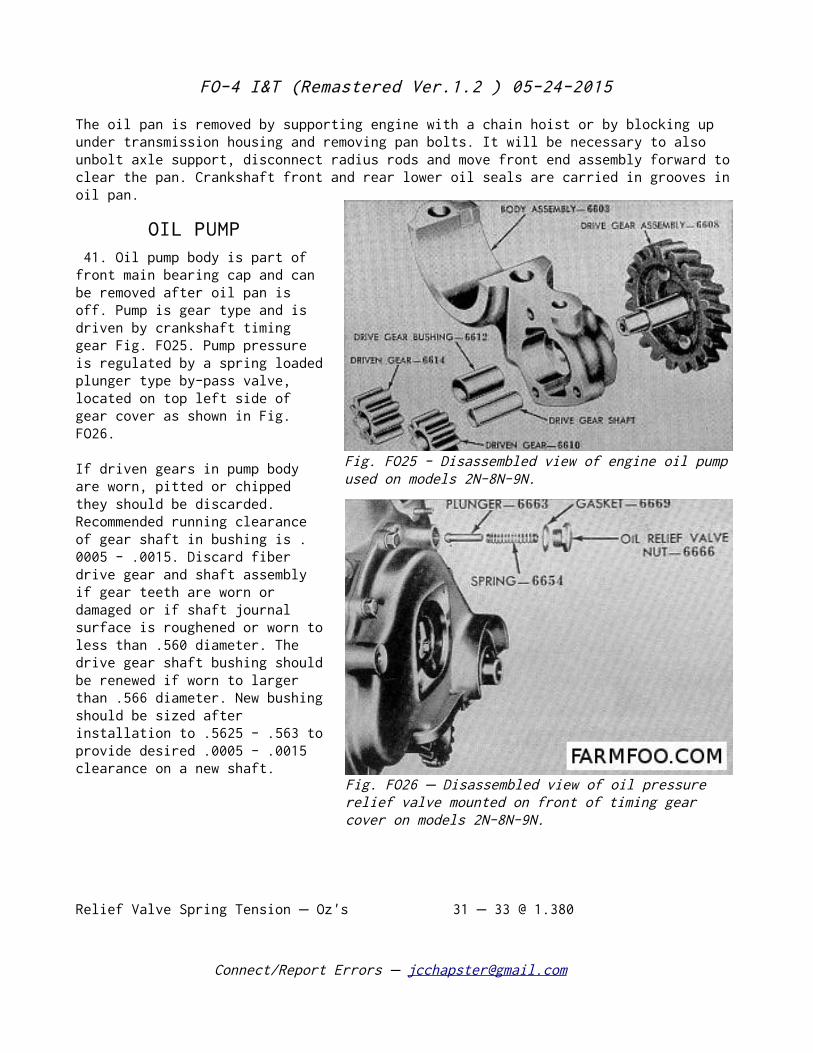
OIL PUMP 41. Oil pump body is part of front main bearing cap and can be removed after oil pan is off. Pump is gear type and is driven by crankshaft timing gear Fig. FO25. Pump pressure is regulated by a spring loaded plunger type by-pass valve, located on top left side of gear cover as shown in Fig. FO26.
If driven gears in pump body are worn, pitted or chipped they should be discarded. Recommended running clearance of gear shaft in bushing is .0005 - .0015. Discard fiber drive gear and shaft assembly if gear teeth are worn or damaged or if shaft journal surface is roughened or worn to less than .560 diameter. The drive gear shaft bushing should be renewed if worn to larger than .566 diameter. New bushing should be sized after installation to .5625 - .563 to provide desired .0005 - .0015 clearance on a new shaft.
Relief Valve Spring Tension Oz's– 31 33 @ 1.380 –
Connect/Report Errors – [email protected]
Fig. FO25 - Disassembled view of engine oil pump used on models 2N-8N-9N.
Fig. FO26 Disassembled view of oil pressure –relief valve mounted on front of timing gear cover on models 2N-8N-9N.
FO-4 I&T (Remastered Ver.1.2 ) 05-24-2015
Gearshaft Clearance in Bushing .0005 - .0015
Idler Gear Clearance on Shaft .0025 - .0045
Cover Screws Torque Ft. Lbs.– 7 10 –
Gear Backlash .003 - .004
Connect/Report Errors – [email protected]
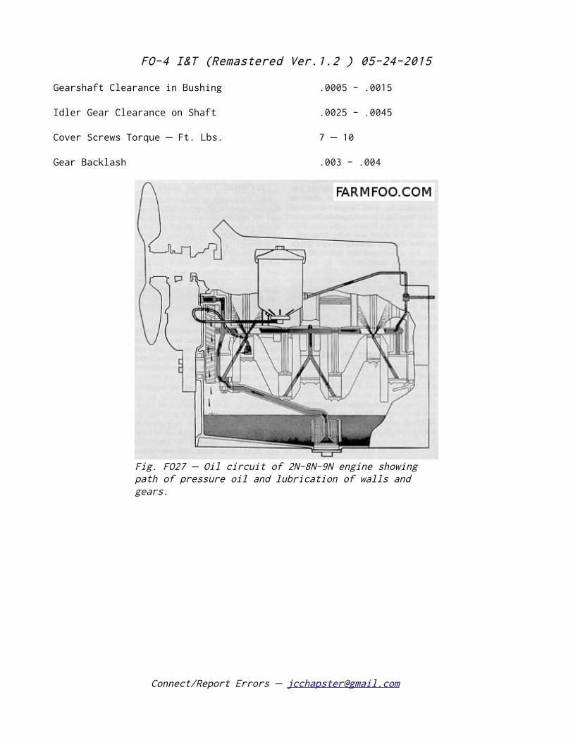
Fig. FO27 Oil circuit of 2N-8N-9N engine showing –path of pressure oil and lubrication of walls and gears.
FO-4 I&T (Remastered Ver.1.2 ) 05-24-2015
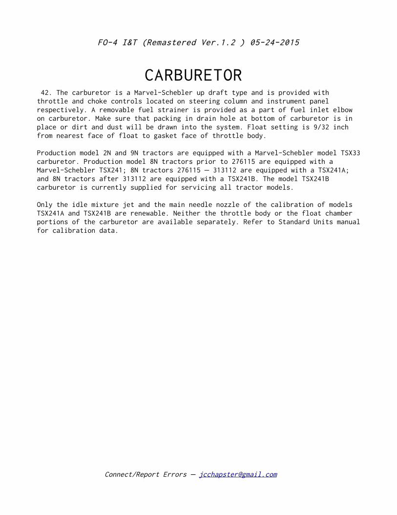
CARBURETOR 42. The carburetor is a Marvel-Schebler up draft type and is provided with throttle and choke controls located on steering column and instrument panel respectively. A removable fuel strainer is provided as a part of fuel inlet elbow on carburetor. Make sure that packing in drain hole at bottom of carburetor is in place or dirt and dust will be drawn into the system. Float setting is 9/32 inch from nearest face of float to gasket face of throttle body.
Production model 2N and 9N tractors are equipped with a Marvel-Schebler model TSX33 carburetor. Production model 8N tractors prior to 276115 are equipped with a Marvel-Schebler TSX241; 8N tractors 276115 313112 are equipped with a TSX241A; –and 8N tractors after 313112 are equipped with a TSX241B. The model TSX241B carburetor is currently supplied for servicing all tractor models.
Only the idle mixture jet and the main needle nozzle of the calibration of models TSX241A and TSX241B are renewable. Neither the throttle body or the float chamber portions of the carburetor are available separately. Refer to Standard Units manual for calibration data.
Connect/Report Errors – [email protected]
FO-4 I&T (Remastered Ver.1.2 ) 05-24-2015
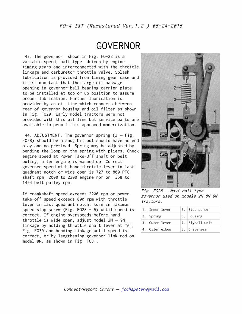
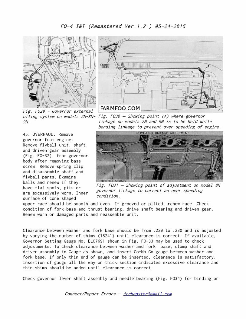
GOVERNOR 43. The governor, shown in Fig. FO-28 is a variable speed, ball type, driven by engine timing gears and interconnected with the throttle linkage and carburetor throttle valve. Splash lubrication is provided from timing gear case and it is important that the large oil passage opening in governor ball bearing carrier plate, to be installed at top or up position to assure proper lubrication. Further lubrication is provided by an oil line which connects between rear of governor housing and oil filter as shown in Fig. FO29. Early model tractors were not provided with this oil line but service parts are available to permit this approved modernization.
44. ADJUSTMENT. The governor spring (2 Fig.– FO28) should be a snug bit but should have no end play and no pre-load. Spring may be adjusted by bending the loop on the spring with pliers. Check engine speed at Power Take-Off shaft or belt pulley, after engine is warmed up. Correct governed speed with hand throttle lever in last quadrant notch or wide open is 727 to 800 PTO shaft rpm, 2000 to 2200 engine rpm or 1358 to 1494 belt pulley rpm.
If crankshaft speed exceeds 2200 rpm or power take-off speed exceeds 800 rpm with throttle lever in last quadrant notch, turn in maximum speed stop screw (Fig. FO28 - 5) until speed is correct. If engine overspeeds before hand throttle is wide open, adjust model 2N 9N– linkage by holding throttle shaft lever at “A”, Fig. FO30 and bending linkage until speed is correct, or by lengthening governor link rod on model 9N, as shown in Fig. FO31.
Connect/Report Errors – [email protected]
Fig. FO28 Novi ball type –governor used on models 2N-8N-9N tractors.
1. Inner lever 5. Stop screw
2. Spring 6. Housing
3. Outer lever 7. Flyball unit
4. Oiler elbow 8. Drive gear
FO-4 I&T (Remastered Ver.1.2 ) 05-24-2015
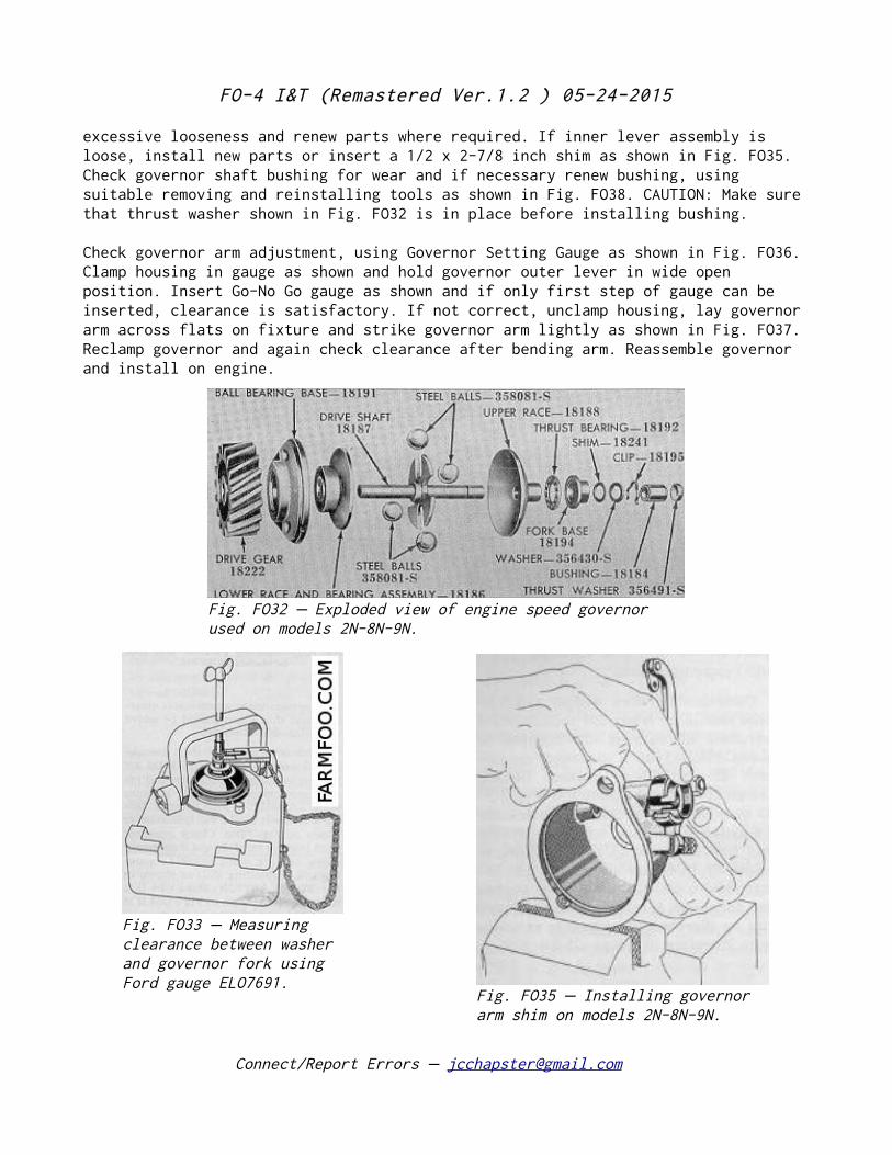
45. OVERHAUL. Remove governor from engine. Remove flyball unit, shaft and driven gear assembly (Fig. FO-32) from governor body after removing base screw. Remove spring clip and disassemble shaft and flyball parts. Examine balls and renew if they have flat spots, pits or are excessively worn. Inner surface of cone shaped upper race should be smooth and even. If grooved or pitted, renew race. Check condition of fork base and thrust bearing, drive shaft bearing and driven gear. Renew worn or damaged parts and reassemble unit.
Clearance between washer and fork base should be from .220 to .230 and is adjusted by varying the number of shims (18241) until clearance is correct. If available, Governor Setting Gauge No. ELO7691 shown in Fig. FO-33 may be used to check adjustments. To check clearance between washer and fork base, clamp shaft and driver assembly in Gauge as shown, and insert Go-No Go gauge between washer and fork base. If only thin end of gauge can be inserted, clearance is satisfactory. Insertion of gauge all the way on thick section indicates excessive clearance and thin shims should be added until clearance is correct.
Check governor lever shaft assembly and needle bearing (Fig. FO34) for binding or
Connect/Report Errors – [email protected]
Fig. FO29 - Governor external oiling system on models 2N-8N-9N.
Fig. FO30 Showing point (A) where governor –linkage on models 2N and 9N is to be held while bending linkage to prevent over speeding of engine.
Fig. FO31 Showing point of adjustment on model 8N –governor linkage to correct an over speeding condition.
FO-4 I&T (Remastered Ver.1.2 ) 05-24-2015
excessive looseness and renew parts where required. If inner lever assembly is loose, install new parts or insert a 1/2 x 2-7/8 inch shim as shown in Fig. FO35. Check governor shaft bushing for wear and if necessary renew bushing, using suitable removing and reinstalling tools as shown in Fig. FO38. CAUTION: Make sure that thrust washer shown in Fig. FO32 is in place before installing bushing.
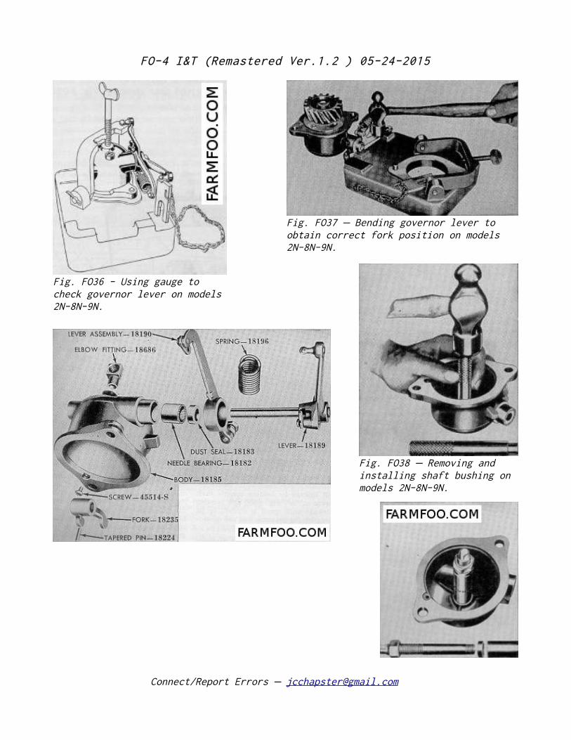
Check governor arm adjustment, using Governor Setting Gauge as shown in Fig. FO36. Clamp housing in gauge as shown and hold governor outer lever in wide open position. Insert Go-No Go gauge as shown and if only first step of gauge can be inserted, clearance is satisfactory. If not correct, unclamp housing, lay governor arm across flats on fixture and strike governor arm lightly as shown in Fig. FO37. Reclamp governor and again check clearance after bending arm. Reassemble governor and install on engine.
Connect/Report Errors – [email protected]
Fig. FO32 Exploded view of engine speed governor –used on models 2N-8N-9N.
Fig. FO33 Measuring –clearance between washer and governor fork using Ford gauge ELO7691.
Fig. FO35 Installing governor –arm shim on models 2N-8N-9N.
FO-4 I&T (Remastered Ver.1.2 ) 05-24-2015
Connect/Report Errors – [email protected]
Fig. FO36 - Using gauge to check governor lever on models 2N-8N-9N.
Fig. FO37 Bending governor lever to –obtain correct fork position on models 2N-8N-9N.
Fig. FO38 Removing and –installing shaft bushing on models 2N-8N-9N.
FO-4 I&T (Remastered Ver.1.2 ) 05-24-2015
COOLING SYSTEM
REMOVE WATER PUMP 46. To remove pump, drain cooling system and remove fan belt. Remove four cap screws holding fan and move fan assembly toward radiator core to clear the pump. Disconnect lower radiator hose. Remove cap screws and stud nuts and remove pump assembly from engine.
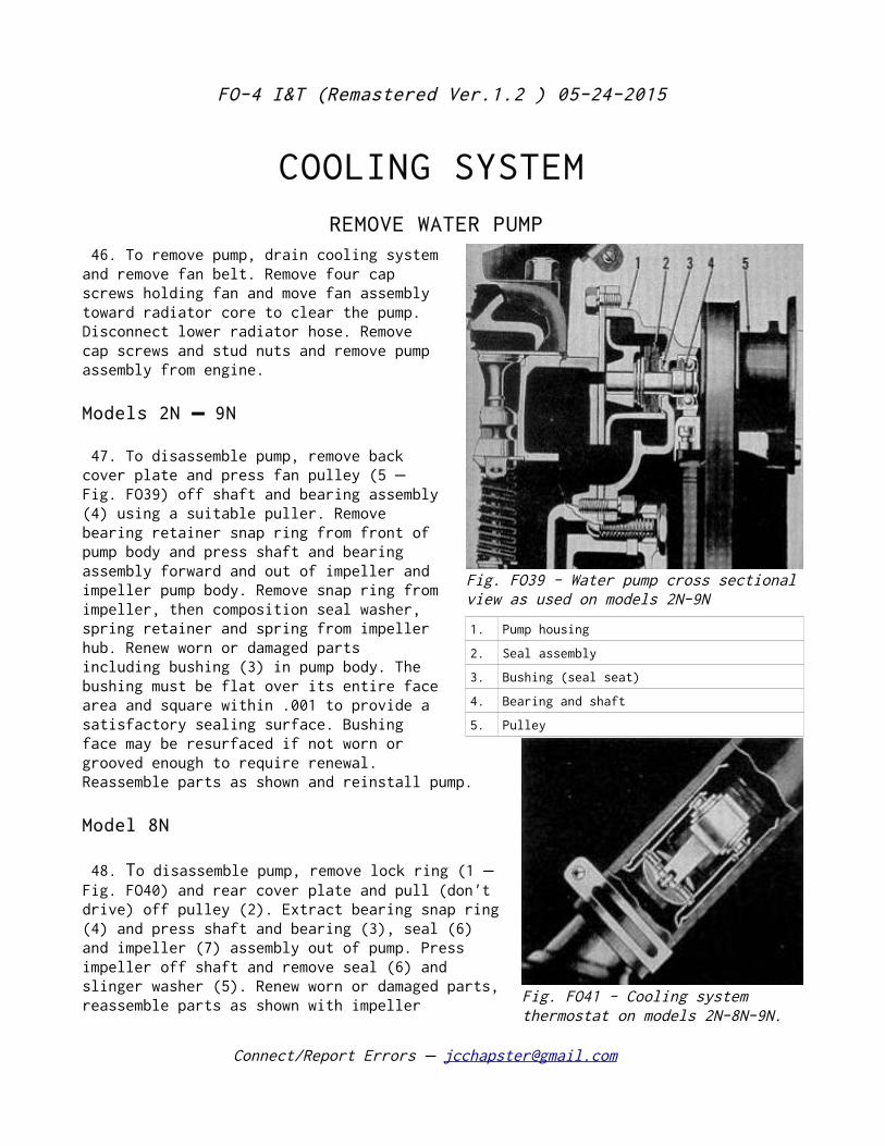
Models 2N 9N –
47. To disassemble pump, remove back cover plate and press fan pulley (5 – Fig. FO39) off shaft and bearing assembly (4) using a suitable puller. Remove bearing retainer snap ring from front of pump body and press shaft and bearing assembly forward and out of impeller and impeller pump body. Remove snap ring from impeller, then composition seal washer, spring retainer and spring from impeller hub. Renew worn or damaged parts including bushing (3) in pump body. The bushing must be flat over its entire face area and square within .001 to provide a satisfactory sealing surface. Bushing face may be resurfaced if not worn or grooved enough to require renewal. Reassemble parts as shown and reinstall pump.
Model 8N
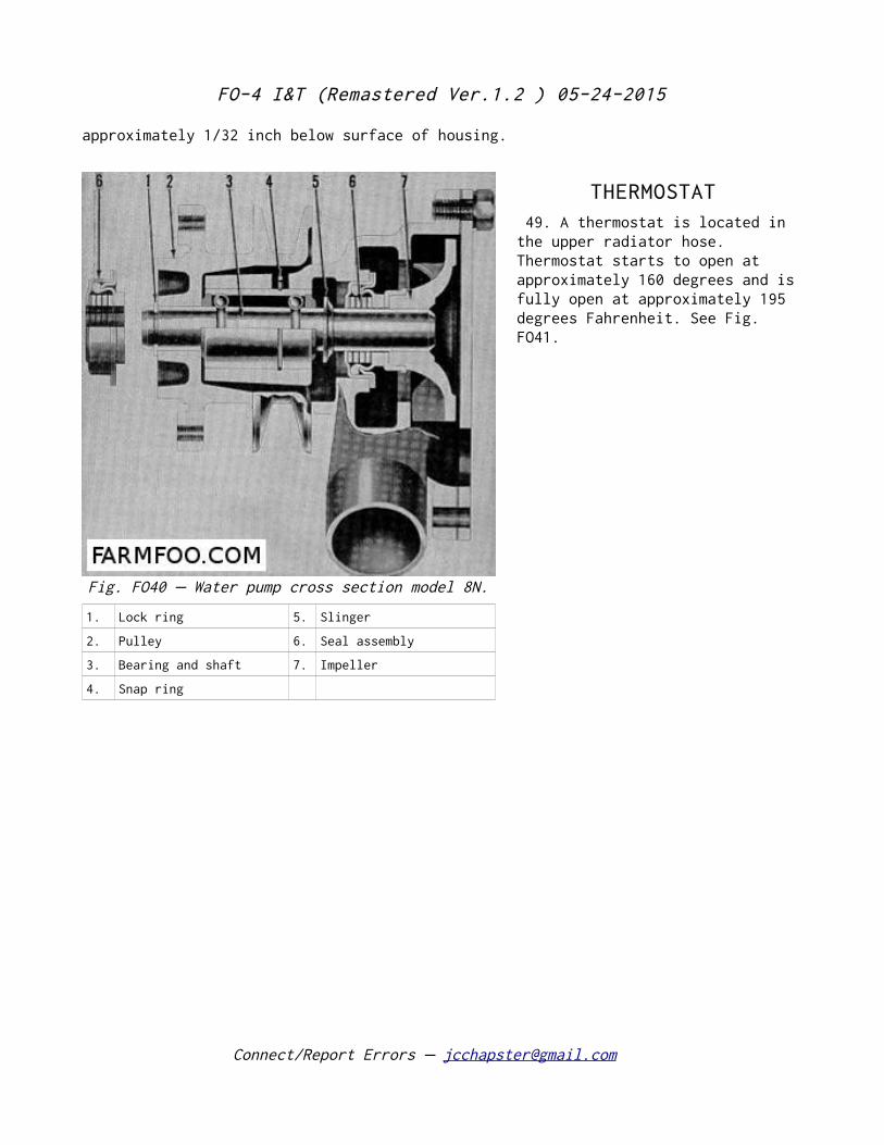
48. To disassemble pump, remove lock ring (1 – Fig. FO40) and rear cover plate and pull (don't drive) off pulley (2). Extract bearing snap ring (4) and press shaft and bearing (3), seal (6) and impeller (7) assembly out of pump. Press impeller off shaft and remove seal (6) and slinger washer (5). Renew worn or damaged parts, reassemble parts as shown with impeller
Connect/Report Errors – [email protected]
Fig. FO39 - Water pump cross sectional view as used on models 2N-9N
1. Pump housing
2. Seal assembly
3. Bushing (seal seat)
4. Bearing and shaft
5. Pulley
Fig. FO41 - Cooling system thermostat on models 2N-8N-9N.
FO-4 I&T (Remastered Ver.1.2 ) 05-24-2015
approximately 1/32 inch below surface of housing.
THERMOSTAT 49. A thermostat is located in the upper radiator hose. Thermostat starts to open at approximately 160 degrees and is fully open at approximately 195 degrees Fahrenheit. See Fig. FO41.
Connect/Report Errors – [email protected]
Fig. FO40 Water pump cross section model 8N.–
1. Lock ring 5. Slinger
2. Pulley 6. Seal assembly
3. Bearing and shaft 7. Impeller
4. Snap ring
FO-4 I&T (Remastered Ver.1.2 ) 05-24-2015
ELECTRICAL AND IGNITION SYSTEM Test Specifications
9N10000C 8N10000 8N10000B 8N10000A 8N10001
Maximum Output 11.5 @ 6.52 11.5 @ 6.52 20.0 @ 7.0 Engine RPM @ Max. Output 925 1500 1100 Field Resistance Ohms 1.5 @ 70°F 4.0 @ 70°F 3.2 @ 70°F Renew Brushes if Shorter Than - Inches .350 .350 .400
GENERATOR AND REGULATOR 50. A two brush 6 volt generator part 8N10000B provided with an external vibrating type voltage regulator replaces the older 3 brush unit 9N10000C, 2N10000 and two brush 8N10000A unit used prior to tractor serial 8N263,844. Generator used on 8N tractors after 263,843 is 8N10001.
51. The cut-out relay 8N10505B used with 3 brush generators should be adjusted to a closing voltage of 7.0 8.5.– Opening voltage should be 1/2 to 1-1/2 volts less than the closing voltage or 6 amperes maximum reverse current at 6 volts minimum.
52. The combined cut-out relay and voltage regulator assemblies 8N10505, 8N10505A and 8N10505B used on 2 brush mounted generators have a cut-out unit and a voltage regulator on the same base. The cut-out relay unit of this assembly should be adjusted to the specifications listed in paragraph 51. The vibrating voltage regulating unit settings should be 6.9 7.4 volts with generator at normal –
Connect/Report Errors – [email protected]
Fig. FO42 - Starter switch mechanism used on models 2N-9N. A basically similar hookup is used on 8N.
FO-4 I&T (Remastered Ver.1.2 ) 05-24-2015
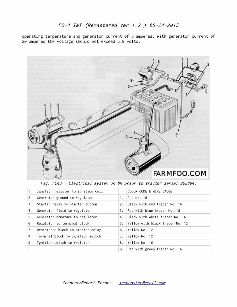
operating temperature and generator current of 5 amperes. With generator current of 20 amperes the voltage should not exceed 6.8 volts.
Connect/Report Errors – [email protected]
Fig. FO43 - Electrical system on 8N prior to tractor serial 263884.
1. Ignition resister to ignition coil COLOR CODE & WIRE GAUGE
2. Generator ground to regulator 1. Red No. 16
3. Starter relay to starter button 2. Black with red tracer No. 16
4. Generator field to regulator 3. Red with blue tracer No. 18
5. Generator armature to regulator 4. Black with white tracer No. 16
6. Regulator to terminal block 5. Yellow with black tracer No. 12
7. Resistance block to starter relay 6. Yellow No. 12
8. Terminal block to ignition switch 7. Yellow No. 12
9. Ignition switch to resistor 8. Yellow No. 16
9. Red with green tracer No. 16
FO-4 I&T (Remastered Ver.1.2 ) 05-24-2015
STARTER MOTOR & SWITCH 53. Ford 6 volt starter and Bendix drive assembly 8N11001 replaces the 9N1101, 9N1102 and 8N1102 assemblies used prior to 1950 production. The 8N11001 starter should have a current draw of: 46-50 amperes @ 5 volts running at no load or 100-150 amperes when cranking a warm engine.
Starter switch on 2N, 8N and 9N is provided with an interlock shown in Fig. FO42 which prevents starting the engine when the tractor is in gear.
BATTERY IGNITION
Models 2N 9N – –Early 8N
54. On 2N, 9N and 8N tractors prior to serial 263844 the Ford 9N12100 battery ignition distributor is mounted on the front face of the timing gear cover directly in line with camshaft. Refer to Fig. FO44. In these installations the front end of the camshaft is slotted to receive a mating tang on the drive end of the distributor shaft. Spark timing at speeds above idling is controlled by a centrifugal governor built into the distributor. Full automatic spark advance is 24 crankshaft degrees, 12 distributor degrees @ 2000 engine rpm. Recommended contact gap is .015 or a dwell of 35-38 degrees. The Ford 91A12300 condenser is of .29-.32 mfd capacity and should have an insulation resistance of
Connect/Report Errors – [email protected]
Fig. FO43A - Schematic wiring diagram used on 8N tractors (with 2 brush generators and angle drive distributors) after tractor serial 263844.
WIRE COLOR CODE & CIRCUITS
16. Red with green tracer Terminal block to ignition lock–
21. Yellow Terminal block to ignition lock–
24. Red Coil to terminal block–
26. Black with red tracer Generator ground to regulator–
32. Red with blue tracer Starter solenoid to starter switch–
35. Black with white tracer Generator field to regulator–
36. Yellow with black tracer Generator armature to regulator–
37. Yellow Regulator to terminal block–
38. Yellow Starter solenoid to terminal block–
FO-4 I&T (Remastered Ver.1.2 ) 05-24-2015
5 megohms @ 210° F.
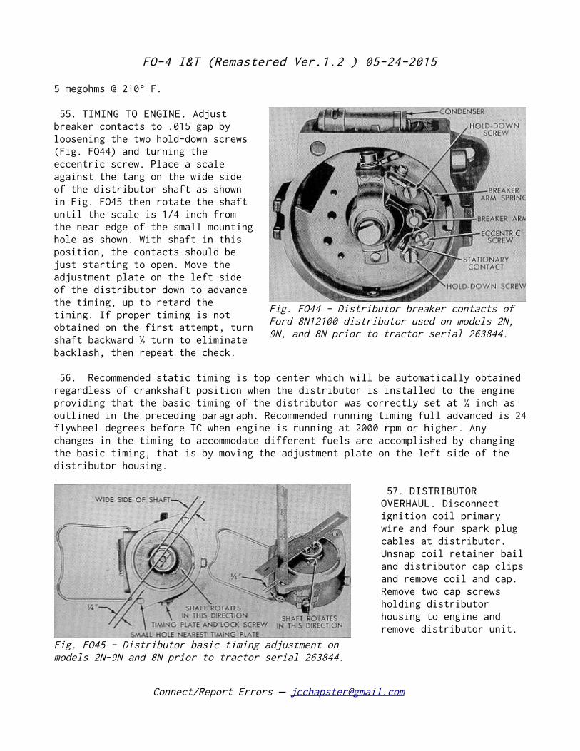
55. TIMING TO ENGINE. Adjust breaker contacts to .015 gap by loosening the two hold-down screws (Fig. FO44) and turning the eccentric screw. Place a scale against the tang on the wide side of the distributor shaft as shown in Fig. FO45 then rotate the shaft until the scale is 1/4 inch from the near edge of the small mounting hole as shown. With shaft in this position, the contacts should be just starting to open. Move the adjustment plate on the left side of the distributor down to advance the timing, up to retard the timing. If proper timing is not obtained on the first attempt, turn shaft backward ½ turn to eliminate backlash, then repeat the check.
56. Recommended static timing is top center which will be automatically obtained regardless of crankshaft position when the distributor is installed to the engine providing that the basic timing of the distributor was correctly set at ¼ inch as outlined in the preceding paragraph. Recommended running timing full advanced is 24 flywheel degrees before TC when engine is running at 2000 rpm or higher. Any changes in the timing to accommodate different fuels are accomplished by changing the basic timing, that is by moving the adjustment plate on the left side of the distributor housing.
57. DISTRIBUTOR OVERHAUL. Disconnect ignition coil primary wire and four spark plug cables at distributor. Unsnap coil retainer bail and distributor cap clips and remove coil and cap. Remove two cap screws holding distributor housing to engine and remove distributor unit.
Connect/Report Errors – [email protected]
Fig. FO44 - Distributor breaker contacts of Ford 8N12100 distributor used on models 2N, 9N, and 8N prior to tractor serial 263844.
Fig. FO45 - Distributor basic timing adjustment on models 2N-9N and 8N prior to tractor serial 263844.
FO-4 I&T (Remastered Ver.1.2 ) 05-24-2015
Loosen condenser lead and mounting screws and remove condenser. Pry out snap ring an remove breaker plate after lock screw is removed. Check distributor shaft fit in housing and breaker plate bracket, check condition of centrifugal advance mechanism, breaker contacts and condenser. Repair or renew parts where necessary an reassemble unit. Adjust breaker contact gap to .014-.016 and lubricate breaker point cam sparingly. See Fig. FO44.
To set basic timing before reinstalling distributor unit, place a steel scale against shaft tang on wide side of shaft and rotate shaft until scale edge is 1/4 inch from top side of small mounting hole as shown in Fig. FO45. When shaft is in that position, breaker contacts should start to open. Move timing plate and screw until contacts open properly.
Install distributor on engine, aligning offset tang and slot, assemble coil and cap and reconnect wiring.
Model 8N (Late) Angle Drive Distributor
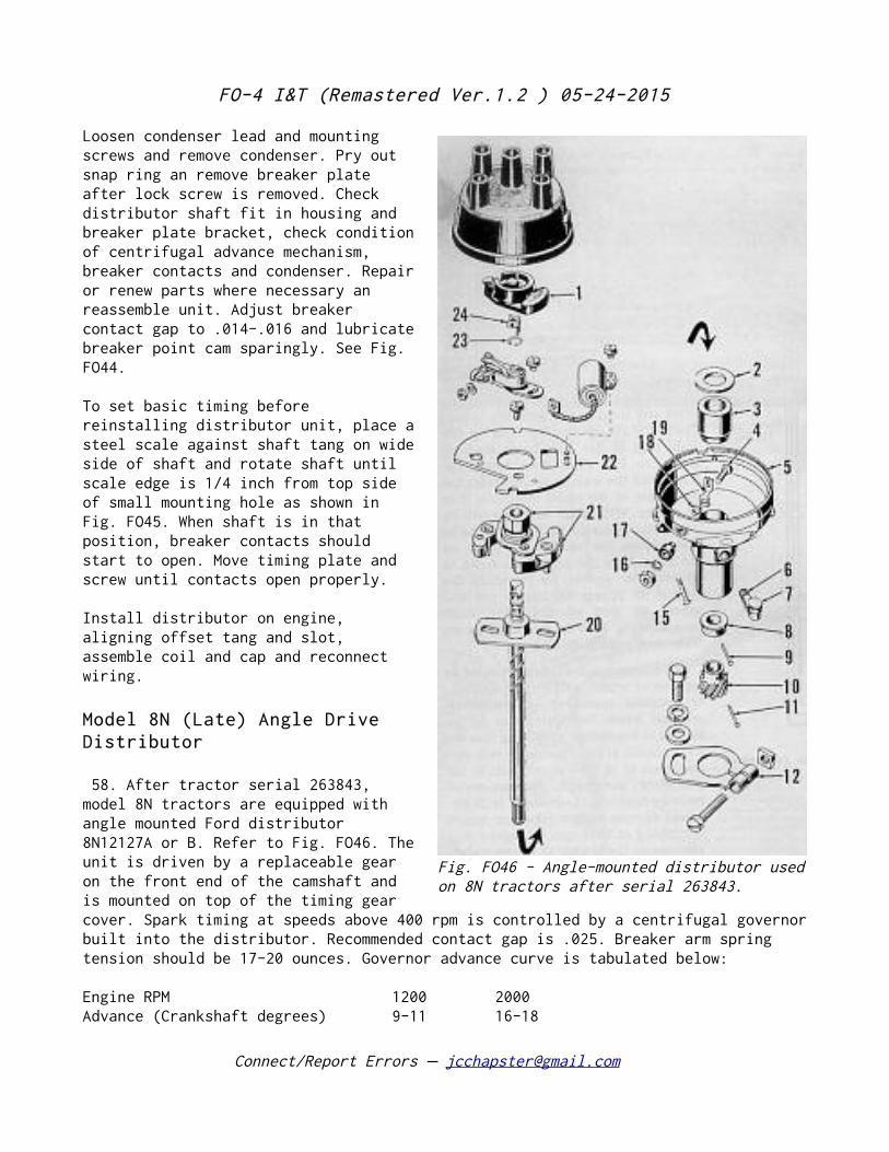
58. After tractor serial 263843, model 8N tractors are equipped with angle mounted Ford distributor 8N12127A or B. Refer to Fig. FO46. The unit is driven by a replaceable gear on the front end of the camshaft and is mounted on top of the timing gear cover. Spark timing at speeds above 400 rpm is controlled by a centrifugal governor built into the distributor. Recommended contact gap is .025. Breaker arm spring tension should be 17-20 ounces. Governor advance curve is tabulated below:
Engine RPM 1200 2000 Advance (Crankshaft degrees) 9-11 16-18
Connect/Report Errors – [email protected]
Fig. FO46 - Angle-mounted distributor used on 8N tractors after serial 263843.
FO-4 I&T (Remastered Ver.1.2 ) 05-24-2015
(For distributor degrees and rpm use 1/2 of the values shown above.)
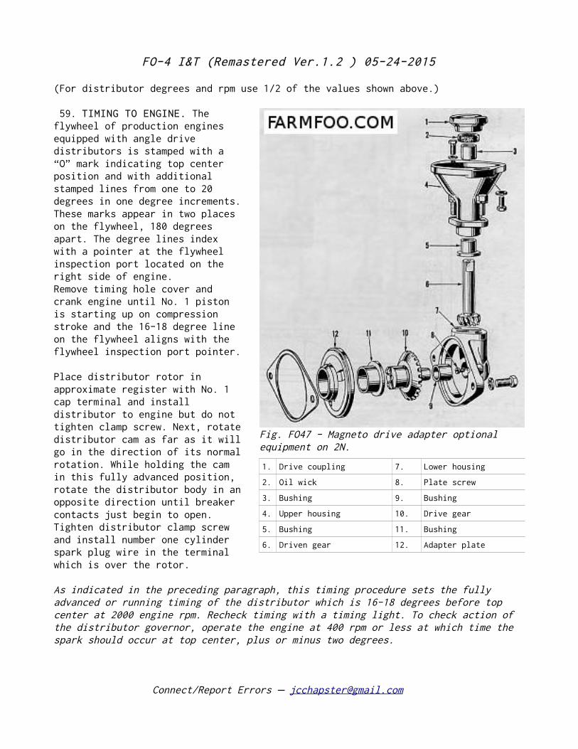
59. TIMING TO ENGINE. The flywheel of production engines equipped with angle drive distributors is stamped with a “O” mark indicating top center position and with additional stamped lines from one to 20 degrees in one degree increments. These marks appear in two places on the flywheel, 180 degrees apart. The degree lines index with a pointer at the flywheel inspection port located on the right side of engine. Remove timing hole cover and crank engine until No. 1 piston is starting up on compression stroke and the 16-18 degree line on the flywheel aligns with the flywheel inspection port pointer.
Place distributor rotor in approximate register with No. 1 cap terminal and install distributor to engine but do not tighten clamp screw. Next, rotate distributor cam as far as it will go in the direction of its normal rotation. While holding the cam in this fully advanced position, rotate the distributor body in an opposite direction until breaker contacts just begin to open. Tighten distributor clamp screw and install number one cylinder spark plug wire in the terminal which is over the rotor.
As indicated in the preceding paragraph, this timing procedure sets the fully advanced or running timing of the distributor which is 16-18 degrees before top center at 2000 engine rpm. Recheck timing with a timing light. To check action of the distributor governor, operate the engine at 400 rpm or less at which time the spark should occur at top center, plus or minus two degrees.
Connect/Report Errors – [email protected]
Fig. FO47 - Magneto drive adapter optional equipment on 2N.
1. Drive coupling 7. Lower housing
2. Oil wick 8. Plate screw
3. Bushing 9. Bushing
4. Upper housing 10. Drive gear
5. Bushing 11. Bushing
6. Driven gear 12. Adapter plate
FO-4 I&T (Remastered Ver.1.2 ) 05-24-2015
60. DISTRIBUTOR OVERHAUL. Procedure for overhaul of the distributor is conventional. When the running clearance of distributor shaft exceeds .006, renew the distributor base bushing or the shaft and bushing.
MAGNETO IGNITION SYSTEM
Model 2N
61. Some model 2N tractors are equipped with magneto ignition systems. A Fairbanks-Morse FM-J4B73 magneto is used and is driven by the camshaft through a magneto drive adapter as shown in Fig. FO47. Refer to Standard Units manual for detailed overhaul and test information on magnetos.
62. MAGNETO TIMING. The magneto mounting flange and mating adapter flange are provided with slotted holes to permit timing adjustment. The magneto uses an impulse coupling with a 15 degree lag angle, which automatically advances spark timing that amount when the engine starts to run. For timing purposes, the impulse coupling should trip when number one piston is at top dead center of compression stroke.
62A. DRIVE ADAPTER OVERHAUL. Adapter is mounted on front of timing gear in same manner as battery ignition distributor. Remove adapter and proceed to disassemble, using care to mark gears and couplings to assure proper reassembly. Renew excessively worn parts, reassemble, install and re-time ignition as previously described.
Connect/Report Errors – [email protected]
FO-4 I&T (Remastered Ver.1.2 ) 05-24-2015
CLUTCH
ADJUSTMENT 63. Free travel of models 2N-9N clutch pedal should be 3/16 inch and for model 8N 3/4 inch. To adjust pedal clearance on models 2N-9N, remove clutch rod clevis pin as shown in Fig. FO48 and screw clevis pin in or out as required and reconnect. Early model 8N tractors have an adjustment screw which is part of clutch pedal as shown in Fig. FO49. Later 8N tractors have a rod linkage system with a clevis adjustment.
REMOVE AND REINSTALL
Models 2N-9N
64. Remove hood and block up tractor under transmission case. Support rear end of engine on a wheeled jack. Disconnect both radius rods and drag links at rear ends. Disconnect battery, starter, generator and ignition wires or cables. Disconnect throttle and choke controls, oil pressure gauge line at cylinder block, air inlet tube at carburetor and
Connect/Report Errors – [email protected]
Fig. FO48 - Clutch pedal adjustment on models 2N-9N.
Fig. FO50 - Front assembly separated from transmission on models 2N-8N-9N.
FO-4 I&T (Remastered Ver.1.2 ) 05-24-2015
exhaust pipe at manifold. Remove bolts holding transmission case to engine and separate engine and transmission as shown in Fig. FO50.
64A. With clutch assembly accessible, mark clutch cover and flywheel to assure correct alignment when reinstalling. Force clutch release levers inward and insert wooden wedges between levers and cover as shown in Fig. FO51. Unscrew cap screws holding clutch assembly to flywheel and remove clutch cover and lined disc. A short, dummy clutch shaft or aligning tool is used as shown when reinstalling clutch. Renew release and pilot bearings if necessary. Install thick side of driven disc hub away from flywheel. When clutch cover is overhauled, reset release levers to the dimensions given in the Long clutch table in Standard Units manual.
Model 8N
65. Block up tractor under transmission case and support rear end of engine on a wheeled jack. Remove storage battery. Disconnect throttle linkage, starter wire at foot button, air inlet tube at carburetor and oil pressure gauge line at cylinder block. Remove cap screws holding steering gear housing, raise gear housing slightly to clear transmission and block up between gear housing and flywheel housing. Disconnect radius rods at rear ends and remove bolts holding engine and transmission case together. Separate engine and transmission.
66. With clutch assembly accessible, mark clutch cover and flywheel to assure correct balance when reinstalling. Force clutch release levers inward and insert wooden wedges between levers and cover as show in Fig. FO51. Unscrew cap screws holding clutch to flywheel and remove clutch cover and lined plate. Renew release and pilot bearings if necessary. Before reinstalling clutch to flywheel lubricate pilot
Connect/Report Errors – [email protected]
Fig. FO49 - Clutch pedal adjustment on model 8N.
Fig. FO51 - Using wooden wedges and dummy shaft to facilitate R&R of clutch. Clutch installation on models 2N-8N-9N.
FO-4 I&T (Remastered Ver.1.2 ) 05-24-2015
bearing with short fiber high melting point type grease. A short dummy clutch shaft or aligning tool is used as shown when reinstalling clutch. Install thick side of lined plate hub away from flywheel. When clutch cover is overhauled check lever settings as for Long 9C clutches as outlined in Standard Units Manual. For renewal of clutch shaft refer to main Drive Gear in Transmission section.
Connect/Report Errors – [email protected]
FO-4 I&T (Remastered Ver.1.2 ) 05-24-2015
TRANSMISSION
REMOVAL
70. Drain transmission and remove power take-off shaft. Split front section of tractor as outlined in paragraphs 64 or 65.
70A. Remove power take-off control from left side of rear center housing. Block up rear section of tractor and unbolt rear section from transmission. Separate transmission and rear section as shown in Fig. FO53 and remove transmission unit.
OVERHAUL
Models 2N-9N (3 Speed)
71. SHIFTER RAILS AND FORKS. Rails and forks may be removed without performing a front section split after steering gear is off and rear section is separated from transmission case as outlined in paragraph 70A. Remove gear shifter rail lock plate (10 Fig. FO52). Pull shifter rails (11) out rearward and remove forks (13 & 14) –being careful not to lose detent balls and springs (12 & 15). Renew worn or damaged parts and reinstall in reverse order of disassembly.
72. MAINSHAFT. After transmission is removed from tractor as outlined in paragraphs 70 and 70A and shifter rails and forks are out proceed as follows: Remove bearing retainer (13-Fig. FO54 or FO56) and shims (12). Move mainshaft toward rear and remove pilot bearing cone (6) using a suitable puller. Pull mainshaft out toward rear and remove sliding gears (7 & 9). Renew worn or damaged parts and reassemble as shown. NOTE: If mainshaft, sliding gears and rear bearing assembly only are to be removed and reinstalled, it will not be necessary to perform the front section split as required for complete transmission removal. Mainshaft and gears may be removed after shifter rods forks are out.
73. Install mainshaft and adjust bearings by varying the number of shims under rear bearing retainer. When bearings are correctly adjusted and sliding gears are in neutral position, 15 to 30 inch pounds torque will be required to turn mainshaft
Connect/Report Errors – [email protected]
Fig. FO53 - Rear assembly separated from transmission on models 2N-8N-9N.
FO-4 I&T (Remastered Ver.1.2 ) 05-24-2015
at rear or output end. The torque test is made with bearings dry and is measured after shaft has started to turn. The test torque is not intended to cover torque necessary to stat shaft rotating from a stationary position.
Connect/Report Errors – [email protected]
FO-4 I&T (Remastered Ver.1.2 ) 05-24-2015
74. MAIN DRIVE GEAR (Clutch Shaft). This gearshaft (5) may be removed after transmission and engine are separated (as in paragraph 64) and steering gear housing is off without disturbing other transmission parts. However, if bearing adjustment is required, it will be necessary to perform the rear section
split (as in paragraph 70A) to gain access to the mainshaft bearing shims 912) which control the adjustment. Remove main drive gear and shaft (5) and bearing retainer (1). Renew worn or damaged parts and reassemble shaft and retainer carefully to prevent damage to oil seal (2) in retainer. Oil seal is installed with seal lip toward rear. Reinstall shaft assembly and check bearing adjustment as described for Mainshaft.
75. COUNTERSHAFT. This shaft (20) may be removed after mainshaft is out and
Connect/Report Errors – [email protected]
Fig. FO54 - Transmission sectional view on models 2N-9N.
5. Main drive gear 9. 2nd & reverse gear
6. Pilot bearing 12. Shims
7. 1st & 3rd gear 13. Bearing retainer
8. Mainshaft 20. Countershaft
Fig FO52 - Gear shifter mechanism on models 2N-9N. Detailed changes were made in the design beginning with tractor serial 12500.
1. Starter switch 9. Shift lever lock
2. Starter push rod 10. Shift rail lock plate
3. Starter rod lever 11. Shifter rails
4. Shifter lever 12. Detent
5. Foot button 13. 2nd and reverse shift fork
6. Cover 14. 1st & 3rd fork
8. Lever spring and lock
15. Detent ball and spring
FO-4 I&T (Remastered Ver.1.2 ) 05-24-2015
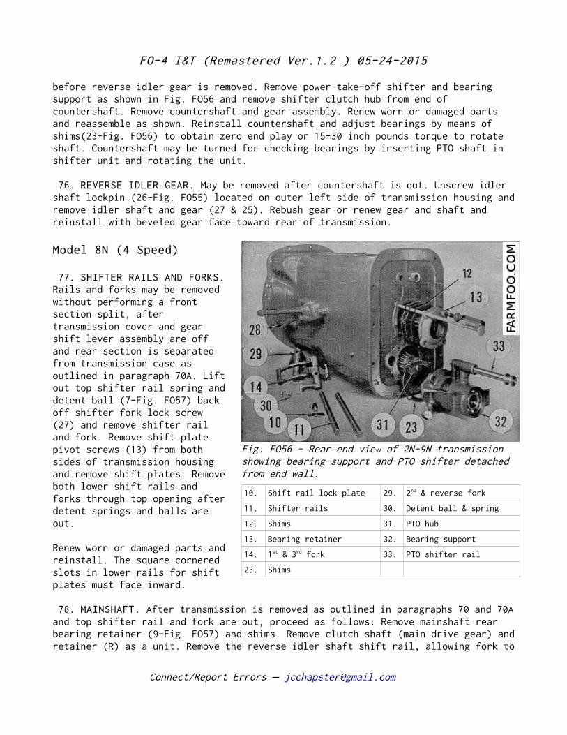
before reverse idler gear is removed. Remove power take-off shifter and bearing support as shown in Fig. FO56 and remove shifter clutch hub from end of countershaft. Remove countershaft and gear assembly. Renew worn or damaged parts and reassemble as shown. Reinstall countershaft and adjust bearings by means of shims(23-Fig. FO56) to obtain zero end play or 15-30 inch pounds torque to rotate shaft. Countershaft may be turned for checking bearings by inserting PTO shaft in shifter unit and rotating the unit.
76. REVERSE IDLER GEAR. May be removed after countershaft is out. Unscrew idler shaft lockpin (26-Fig. FO55) located on outer left side of transmission housing and remove idler shaft and gear (27 & 25). Rebush gear or renew gear and shaft and reinstall with beveled gear face toward rear of transmission.
Model 8N (4 Speed)
77. SHIFTER RAILS AND FORKS. Rails and forks may be removed without performing a front section split, after transmission cover and gear shift lever assembly are off and rear section is separated from transmission case as outlined in paragraph 70A. Lift out top shifter rail spring and detent ball (7-Fig. FO57) back off shifter fork lock screw (27) and remove shifter rail and fork. Remove shift plate pivot screws (13) from both sides of transmission housing and remove shift plates. Remove both lower shift rails and forks through top opening after detent springs and balls are out.
Renew worn or damaged parts and reinstall. The square cornered slots in lower rails for shift plates must face inward.
78. MAINSHAFT. After transmission is removed as outlined in paragraphs 70 and 70A and top shifter rail and fork are out, proceed as follows: Remove mainshaft rear bearing retainer (9-Fig. FO57) and shims. Remove clutch shaft (main drive gear) and retainer (R) as a unit. Remove the reverse idler shaft shift rail, allowing fork to
Connect/Report Errors – [email protected]
Fig. FO56 - Rear end view of 2N-9N transmission showing bearing support and PTO shifter detached from end wall.
10. Shift rail lock plate 29. 2nd & reverse fork
11. Shifter rails 30. Detent ball & spring
12. Shims 31. PTO hub
13. Bearing retainer 32. Bearing support
14. 1st & 3rd fork 33. PTO shifter rail
23. Shims
FO-4 I&T (Remastered Ver.1.2 ) 05-24-2015
remain in housing. Lift out the mainshaft and gear cluster as a unit. Renew worn or damaged parts and reinstall shaft and gears, assembling in order shown in Fig. FO59. Move shifter forks to neutral position and check mainshaft bearing adjustment.
78A. To test bearing adjustment, rotate mainshaft rear or output end with transmission in neutral, and measure turning torque. If torque is 20 to 35 inch pounds measured with shaft in motion, bearing adjustment is correct. Vary the number of shims (S) under rear bearing retainer if adjustment is necessary.
Connect/Report Errors – [email protected]
FO-4 I&T (Remastered Ver.1.2 ) 05-24-2015
79. MAIN DRIVE GEAR (Clutch Shaft). This gearshaft (1-Fig. FO57) may be removed after transmission and engine are separated (as in paragraph 65). However, if bearing adjustment is required it will be necessary to perform the rear section split (as in paragraph 70A) to gain access to the mainshaft bearing shims (S) which control the adjustment. Remove gearshaft and retainer (R) as a unit. Renew worn or damaged parts and reassemble shaft and retainer carefully to prevent damage to the oil seal in the retainer. Lip of oil seal should face towards rear. After shaft is reinstalled check bearing adjustment and if necessary readjust as outlined in paragraph 78A.
Connect/Report Errors – [email protected]
Fig. FO55 - Transmission gears and shafts on models 2N-9N.
1. Bearing retainer 10. Bearing cone 19. Snap ring
2. Oil seal 11. Bearing cup 20. Countershaft
3. Bearing cup 12. Shim 21. Bearing
4. Bearing cone 13. Bearing retainer 22. Bearing cup
5. Main drive gear 14. Bearing retainer 23. Shims
6. Pilot bearing 15. Gasket 24. Bushing
7. 1st & 3rd gear 16. Bearing cup 25. Reverse idler gear
8. Mainshaft 17. Bearing cone 26. Shaft lock pin
9. 2nd & reverse gear 18. Countershaft gear 27. Idler gear shaft
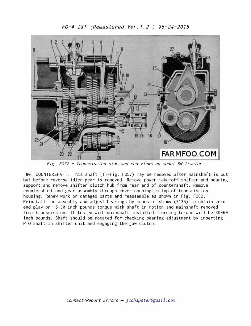
FO-4 I&T (Remastered Ver.1.2 ) 05-24-2015
80. COUNTERSHAFT. This shaft (11-Fig. FO57) may be removed after mainshaft is out but before reverse idler gear is removed. Remove power take-off shifter and bearing support and remove shifter clutch hub from rear end of countershaft. Remove countershaft and gear assembly through cover opening in top of transmission housing. Renew work or damaged parts and reassemble as shown in Fig. FO62. Reinstall the assembly and adjust bearings by means of shims (7135) to obtain zero end play or 15-30 inch pounds torque with shaft in motion and mainshaft removed from transmission. If tested with mainshaft installed, turning torque will be 30-60 inch pounds. Shaft should be rotated for checking bearing adjustment by inserting PTO shaft in shifter unit and engaging the jaw clutch.
Connect/Report Errors – [email protected]
Fig. FO57 - Transmission side and end views on model 8N tractor.
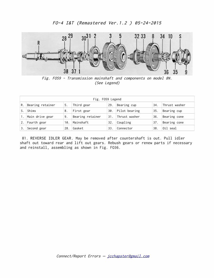
FO-4 I&T (Remastered Ver.1.2 ) 05-24-2015
Fig. FO59 Legend
R. Bearing retainer 5. Third gear 29. Bearing cup 34. Thrust washer
S. Shims 8. First gear 30. Pilot bearing 35. Bearing cup
1. Main drive gear 9. Bearing retainer 31. Thrust washer 36. Bearing cone
2. Fourth gear 10. Mainshaft 32. Coupling 37. Bearing cone
3. Second gear 28. Gasket 33. Connector 38. Oil seal
81. REVERSE IDLER GEAR. May be removed after countershaft is out. Pull idler shaft out toward rear and lift out gears. Rebush gears or renew parts if necessary and reinstall, assembling as shown in Fig. FO36.
Connect/Report Errors – [email protected]
Fig. FO59 - Transmission mainshaft and components on model 8N.(See Legend)
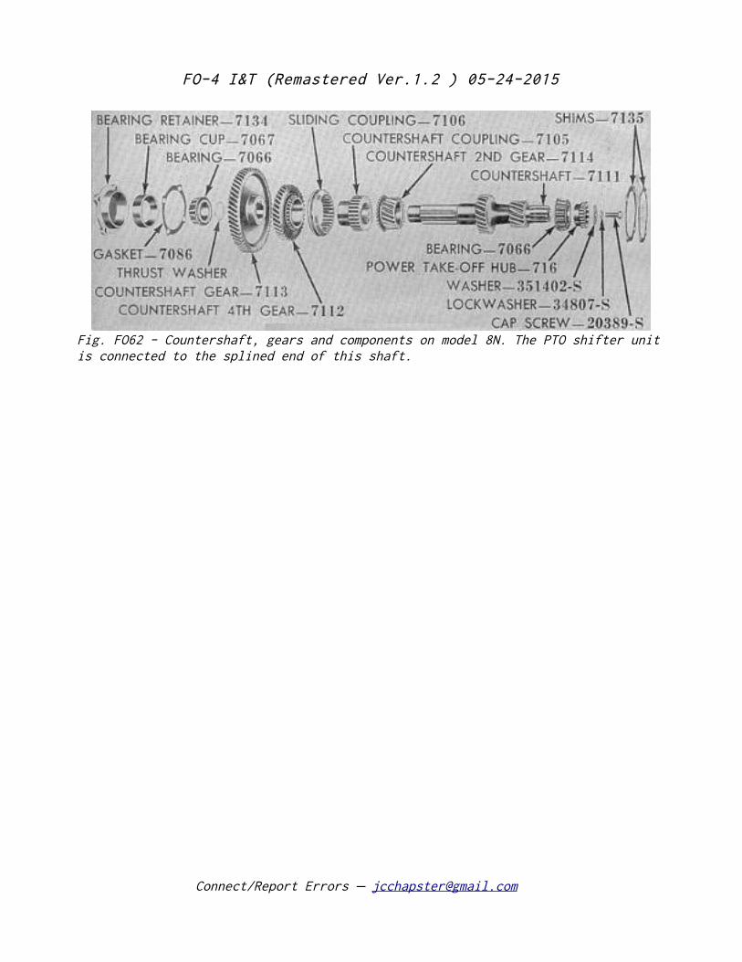
FO-4 I&T (Remastered Ver.1.2 ) 05-24-2015
Connect/Report Errors – [email protected]
Fig. FO62 - Countershaft, gears and components on model 8N. The PTO shifter unit is connected to the splined end of this shaft.
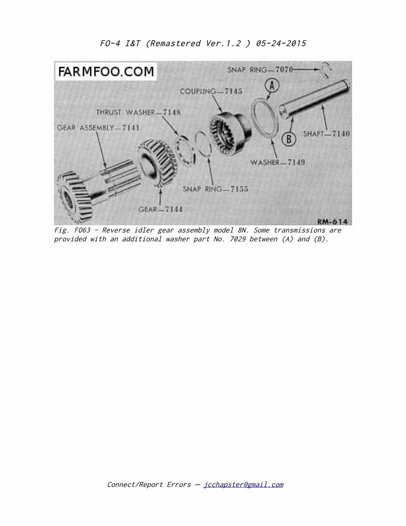
FO-4 I&T (Remastered Ver.1.2 ) 05-24-2015
Connect/Report Errors – [email protected]
Fig. FO63 - Reverse idler gear assembly model 8N. Some transmissions are provided with an additional washer part No. 7029 between (A) and (B).
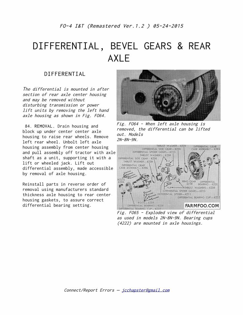
FO-4 I&T (Remastered Ver.1.2 ) 05-24-2015
DIFFERENTIAL, BEVEL GEARS & REAR AXLE
DIFFERENTIAL
The differential is mounted in after section of rear axle center housing and may be removed without disturbing transmission or power lift units by removing the left hand axle housing as shown in Fig. FO64.
84. REMOVAL. Drain housing and block up under center center axle housing to raise rear wheels. Remove left rear wheel. Unbolt left axle housing assembly from center housing and pull assembly off tractor with axle shaft as a unit, supporting it with a lift or wheeled jack. Lift out differential assembly, made accessible by removal of axle housing.
Reinstall parts in reverse order of removal using manufacturers standard thickness axle housing to rear center housing gaskets, to assure correct differential bearing setting.
Connect/Report Errors – [email protected]
Fig. FO64 - When left axle housing is removed, the differential can be lifted out. Models 2N-8N-9N.
Fig. FO65 - Exploded view of differential as used in models 2N-8N-9N. Bearing cups (4222) are mounted in axle housings.
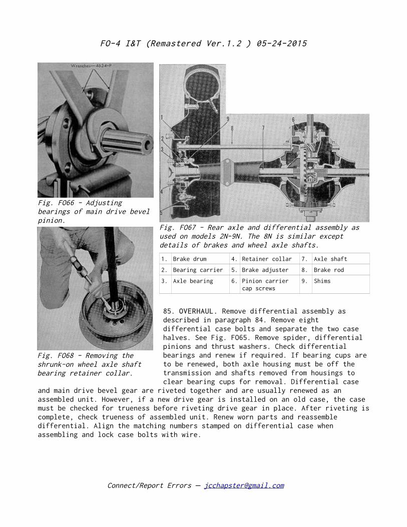
FO-4 I&T (Remastered Ver.1.2 ) 05-24-2015
85. OVERHAUL. Remove differential assembly as described in paragraph 84. Remove eight differential case bolts and separate the two case halves. See Fig. FO65. Remove spider, differential pinions and thrust washers. Check differential bearings and renew if required. If bearing cups are to be renewed, both axle housing must be off the transmission and shafts removed from housings to clear bearing cups for removal. Differential case
and main drive bevel gear are riveted together and are usually renewed as an assembled unit. However, if a new drive gear is installed on an old case, the case must be checked for trueness before riveting drive gear in place. After riveting is complete, check trueness of assembled unit. Renew worn parts and reassemble differential. Align the matching numbers stamped on differential case when assembling and lock case bolts with wire.
Connect/Report Errors – [email protected]
Fig. FO67 - Rear axle and differential assembly as used on models 2N-9N. The 8N is similar except details of brakes and wheel axle shafts.
1. Brake drum 4. Retainer collar 7. Axle shaft
2. Bearing carrier 5. Brake adjuster 8. Brake rod
3. Axle bearing 6. Pinion carrier cap screws
9. Shims
Fig. FO66 - Adjusting bearings of main drive bevel pinion.
Fig. FO68 - Removing the shrunk-on wheel axle shaft bearing retainer collar.
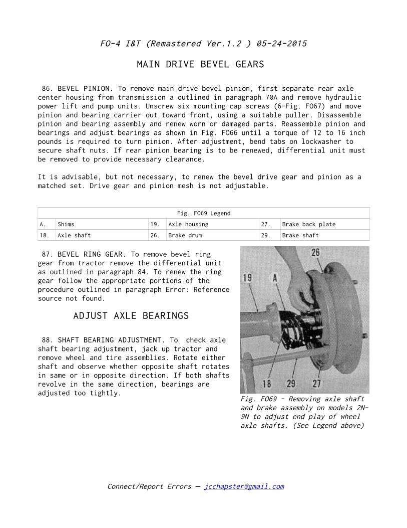
FO-4 I&T (Remastered Ver.1.2 ) 05-24-2015
MAIN DRIVE BEVEL GEARS
86. BEVEL PINION. To remove main drive bevel pinion, first separate rear axle center housing from transmission a outlined in paragraph 70A and remove hydraulic power lift and pump units. Unscrew six mounting cap screws (6-Fig. FO67) and move pinion and bearing carrier out toward front, using a suitable puller. Disassemble pinion and bearing assembly and renew worn or damaged parts. Reassemble pinion and bearings and adjust bearings as shown in Fig. FO66 until a torque of 12 to 16 inch pounds is required to turn pinion. After adjustment, bend tabs on lockwasher to secure shaft nuts. If rear pinion bearing is to be renewed, differential unit must be removed to provide necessary clearance.
It is advisable, but not necessary, to renew the bevel drive gear and pinion as a matched set. Drive gear and pinion mesh is not adjustable.
Fig. FO69 Legend
A. Shims 19. Axle housing 27. Brake back plate
18. Axle shaft 26. Brake drum 29. Brake shaft
87. BEVEL RING GEAR. To remove bevel ring gear from tractor remove the differential unit as outlined in paragraph 84. To renew the ring gear follow the appropriate portions of the procedure outlined in paragraph Error: Referencesource not found.
ADJUST AXLE BEARINGS
88. SHAFT BEARING ADJUSTMENT. To check axle shaft bearing adjustment, jack up tractor and remove wheel and tire assemblies. Rotate either shaft and observe whether opposite shaft rotates in same or in opposite direction. If both shafts revolve in the same direction, bearings are adjusted too tightly.
Connect/Report Errors – [email protected]
Fig. FO69 - Removing axle shaft and brake assembly on models 2N-9N to adjust end play of wheel axle shafts. (See Legend above)
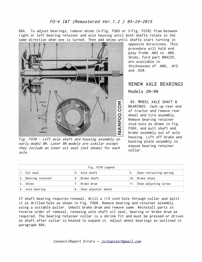
FO-4 I&T (Remastered Ver.1.2 ) 05-24-2015
88A. To adjust bearings, remove shims (A-Fig. FO69 or 3-Fig. FO70) from between right or left bearing retainer and axle housing until both shafts rotate in the same direction when one is turned. Then add shims until shafts start turning in
opposite directions. This procedure will hold end play fro9m .002 to .006. Shims, Ford part 8N4229, are available in thicknesses of .008, .015 and .020.
RENEW AXLE BEARINGS
Models 2N-9N
89. WHEEL AXLE SHAFT & BEARINGS. Jack up rear end of tractor and remove rear wheel and tire assembly. Remove bearing retainer stud nuts as shown in Fig. FO69, and pull shaft and brake assembly out of axle housing. Lift off brake and backing plate assembly to expose bearing retainer collar.
Fig. FO70 Legend
1. Oil seal 5. Axle shaft 9. Shoe retracting spring
2. Bearing retainer 6. Brake shaft 10. Brake shoes
3. Shims 7. Brake drum 11. Shoe adjusting screw
4. Axle bearing 8. Shoe adjuster wheel
If shaft bearing requires renewal, drill a 1/4 inch hole through collar and split it at drilled hole as shown in Fig. FO68. Remove bearing and retainer assembly using a suitable puller. Unbolt brake drum and remove same. Reinstall parts in reverse order of removal, renewing axle shaft oil seal, bearing or brake drum as required. The bearing retainer collar is a shrink fit and must be pressed or driven on shaft after collar is heated to expand it. Adjust wheel bearings as outlined in paragraph 88A.
Connect/Report Errors – [email protected]
Fig. FO70 - Left axle shaft and housing assembly on early model 8N. Later 8N models are similar except they include an inner oil seal (not shown) for each axle.
FO-4 I&T (Remastered Ver.1.2 ) 05-24-2015
Model 8N
90. WHEEL AXLE SHAFT AND BEARINGS. Jack up rear end of tractor and remove the rear wheel and tire assembly. Remove brake drum as shown in Fig. FO71 and use a suitable puller to remove wheel hub. Remove bearing retainer stud nuts and pull retainer and brake assembly off axle housing. Pull axle shaft out of axle housing. Wheel axle shaft bearings can be renewed at this time. Reinstall parts in reverse order of removal. Adjust wheel bearings as outlined in paragraph 88A. Tighten axle shaft nut using 450 foot pounds torque and install lock ring. Refer also to Fig. FO-70.
Connect/Report Errors – [email protected]
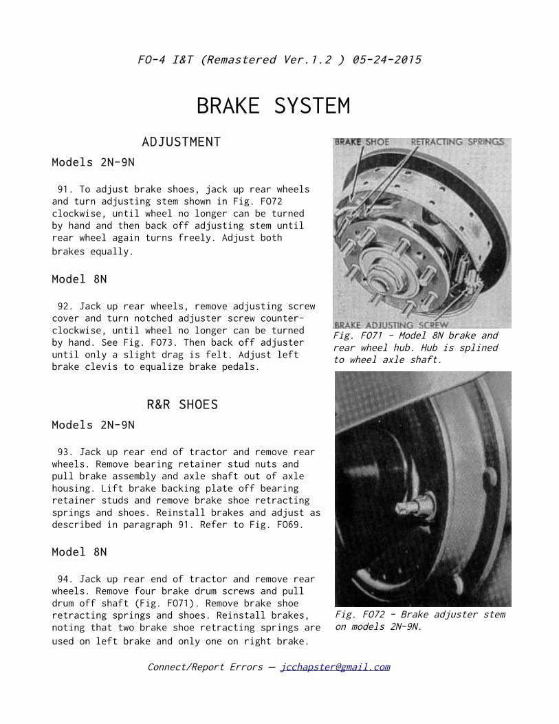
FO-4 I&T (Remastered Ver.1.2 ) 05-24-2015
BRAKE SYSTEM
ADJUSTMENT
Models 2N-9N
91. To adjust brake shoes, jack up rear wheels and turn adjusting stem shown in Fig. FO72 clockwise, until wheel no longer can be turned by hand and then back off adjusting stem until rear wheel again turns freely. Adjust both brakes equally.
Model 8N
92. Jack up rear wheels, remove adjusting screw cover and turn notched adjuster screw counter-clockwise, until wheel no longer can be turned by hand. See Fig. FO73. Then back off adjuster until only a slight drag is felt. Adjust left brake clevis to equalize brake pedals.
R&R SHOES
Models 2N-9N
93. Jack up rear end of tractor and remove rear wheels. Remove bearing retainer stud nuts and pull brake assembly and axle shaft out of axle housing. Lift brake backing plate off bearing retainer studs and remove brake shoe retracting springs and shoes. Reinstall brakes and adjust as described in paragraph 91. Refer to Fig. FO69.
Model 8N
94. Jack up rear end of tractor and remove rear wheels. Remove four brake drum screws and pull drum off shaft (Fig. FO71). Remove brake shoe retracting springs and shoes. Reinstall brakes, noting that two brake shoe retracting springs are used on left brake and only one on right brake.
Connect/Report Errors – [email protected]
Fig. FO71 - Model 8N brake and rear wheel hub. Hub is splined to wheel axle shaft.
Fig. FO72 - Brake adjuster stem on models 2N-9N.
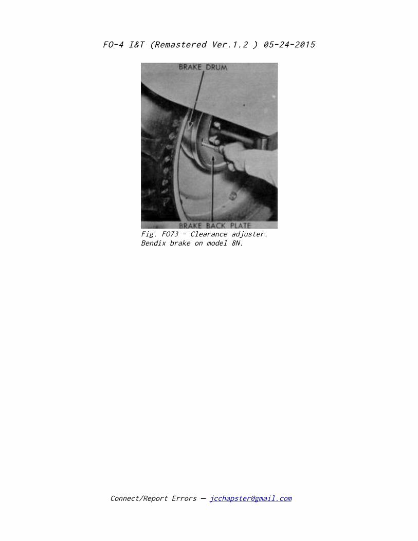
FO-4 I&T (Remastered Ver.1.2 ) 05-24-2015
Connect/Report Errors – [email protected]
Fig. FO73 - Clearance adjuster. Bendix brake on model 8N.
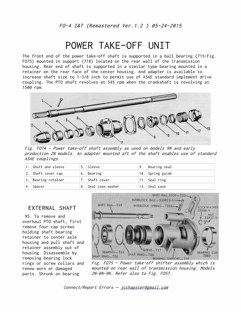
FO-4 I&T (Remastered Ver.1.2 ) 05-24-2015
POWER TAKE-OFF UNIT The front end of the power take-off shaft is supported in a ball bearing (715-Fig. FO75) mounted in support (718) located on the rear wall of the transmission housing. Rear end of shaft is supported in a similar type bearing mounted in a retainer on the rear face of the center housing. And adapter is available to increase shaft size to 1-3/8 inch to permit use of ASAE standard implement drive coupling. The PTO shaft revolves at 545 rpm when the crankshaft is revolving at 1500 rpm.
EXTERNAL SHAFT 95. To remove and overhaul PTO shaft, first remove four cap screws holding shaft bearing retainer to center axle housing and pull shaft and retainer assembly out of housing. Disassemble by removing bearing lock rings or screw collars and renew worn or damaged parts. Shrunk on bearing
Connect/Report Errors – [email protected]
Fig. FO74 - Power take-off shaft assembly as used on models 9N and early production 2N models. An adapter mounted aft of the shaft enables use of standard ASAE couplings.
1. Shaft and sleeve 5. Sleeve 9. Bearing seal
2. Shaft cover cap 6. Bearing 10. Spring guide
3. Bearing retainer 7. Shaft cover 11. Seal ring
4. Spacer 8. Seal case washer 13. Seal case
Fig. FO75 - Power take-off shifter assembly which is mounted on rear wall of transmission housing. Models 2N-8N-9N. Refer also to Fig. FO57.
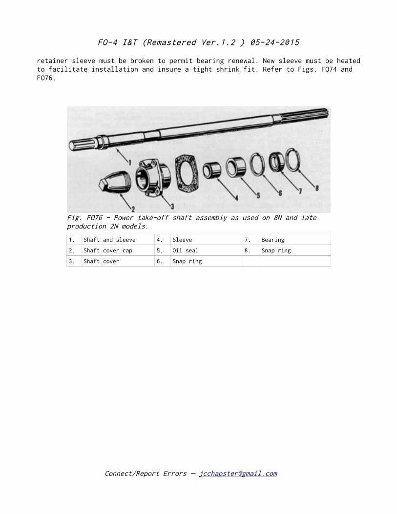
FO-4 I&T (Remastered Ver.1.2 ) 05-24-2015
retainer sleeve must be broken to permit bearing renewal. New sleeve must be heated to facilitate installation and insure a tight shrink fit. Refer to Figs. FO74 and FO76.
Connect/Report Errors – [email protected]
Fig. FO76 - Power take-off shaft assembly as used on 8N and late production 2N models.
1. Shaft and sleeve 4. Sleeve 7. Bearing
2. Shaft cover cap 5. Oil seal 8. Snap ring
3. Shaft cover 6. Snap ring
FO-4 I&T (Remastered Ver.1.2 ) 05-24-2015
SHIFTER UNIT 96. To remove the shifter and shaft front bearing unit from the tractor, detach the center housing from the rear of the transmission housing as outlined in paragraph 70A or remove the hydraulic lift cover assembly from the center housing. Remove the cap screws retaining the unit to the rear wall of the transmission housing Fig. FO56. Procedure for overhaul is self-evident after examining the unit or the components as shown in Fig. FO75.
Connect/Report Errors – [email protected]
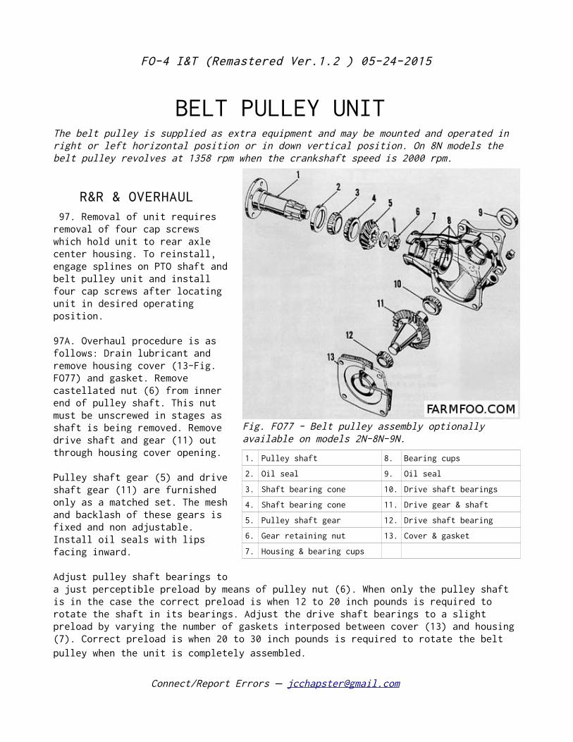
FO-4 I&T (Remastered Ver.1.2 ) 05-24-2015
BELT PULLEY UNIT The belt pulley is supplied as extra equipment and may be mounted and operated in right or left horizontal position or in down vertical position. On 8N models the belt pulley revolves at 1358 rpm when the crankshaft speed is 2000 rpm.
R&R & OVERHAUL 97. Removal of unit requires removal of four cap screws which hold unit to rear axle center housing. To reinstall, engage splines on PTO shaft and belt pulley unit and install four cap screws after locating unit in desired operating position.
97A. Overhaul procedure is as follows: Drain lubricant and remove housing cover (13-Fig. FO77) and gasket. Remove castellated nut (6) from inner end of pulley shaft. This nut must be unscrewed in stages as shaft is being removed. Remove drive shaft and gear (11) out through housing cover opening.
Pulley shaft gear (5) and drive shaft gear (11) are furnished only as a matched set. The mesh and backlash of these gears is fixed and non adjustable. Install oil seals with lips facing inward.
Adjust pulley shaft bearings to a just perceptible preload by means of pulley nut (6). When only the pulley shaft is in the case the correct preload is when 12 to 20 inch pounds is required to rotate the shaft in its bearings. Adjust the drive shaft bearings to a slight preload by varying the number of gaskets interposed between cover (13) and housing (7). Correct preload is when 20 to 30 inch pounds is required to rotate the belt pulley when the unit is completely assembled.
Connect/Report Errors – [email protected]
Fig. FO77 - Belt pulley assembly optionally available on models 2N-8N-9N.
1. Pulley shaft 8. Bearing cups
2. Oil seal 9. Oil seal
3. Shaft bearing cone 10. Drive shaft bearings
4. Shaft bearing cone 11. Drive gear & shaft
5. Pulley shaft gear 12. Drive shaft bearing
6. Gear retaining nut 13. Cover & gasket
7. Housing & bearing cups
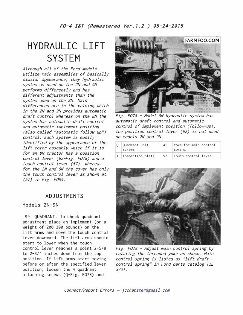
FO-4 I&T (Remastered Ver.1.2 ) 05-24-2015
HYDRAULIC LIFT SYSTEM
Although all of the Ford models utilize main assemblies of basically similar appearance, they hydraulic system as used on the 2N and 9N performs differently and has different adjustments than the system used on the 8N. Main differences are in the valving which in the 2N and 9N provides automatic draft control whereas on the 8N the system has automatic draft control and automatic implement position (also called “automatic follow up”) control. Each system is easily identified by the appearance of the lift cover assembly which if it is for an 8N tractor has a position control lever (62-Fig. FO78) and a touch control lever (57), whereas for the 2N and 9N the cover has only the touch control lever as shown at (57) in Fig. FO84.
ADJUSTMENTS
Models 2N-9N
99. QUADRANT. To check quadrant adjustment place an implement (or a weight of 200-300 pounds) on the lift arms and move the touch control lever downward. The lift arms should start to lower when the touch control lever reaches a point 2-5/8 to 2-3/4 inches down from the top position. If lift arms start moving before or after the specified lever position, loosen the 4 quadrant attaching screws (Q-Fig. FO78) and
Connect/Report Errors – [email protected]
Fig. FO78 - Model 8N hydraulic system has automatic draft control and automatic control of implement position (follow-up). the position control lever (62) is not used on models 2N and 9N.
Q. Quadrant unit screws
41. Yoke for main control spring
X. Inspection plate 57. Touch control lever
Fig. FO79 - Adjust main control spring by rotating the threaded yoke as shown. Main control spring is listed as "lift draft control spring" in Ford parts catalog TIE 3731.
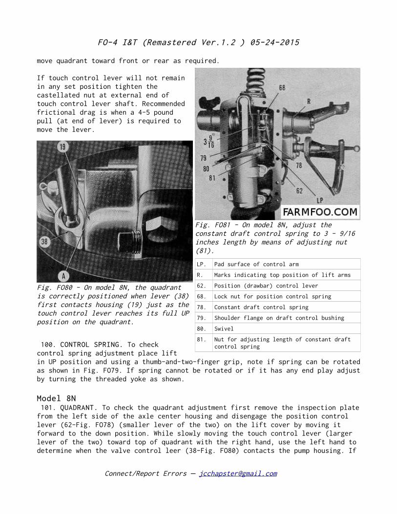
FO-4 I&T (Remastered Ver.1.2 ) 05-24-2015
move quadrant toward front or rear as required.
If touch control lever will not remain in any set position tighten the castellated nut at external end of touch control lever shaft. Recommended frictional drag is when a 4-5 pound pull (at end of lever) is required to move the lever.
100. CONTROL SPRING. To check control spring adjustment place lift in UP position and using a thumb-and-two-finger grip, note if spring can be rotated as shown in Fig. FO79. If spring cannot be rotated or if it has any end play adjust by turning the threaded yoke as shown.
Model 8N 101. QUADRANT. To check the quadrant adjustment first remove the inspection plate from the left side of the axle center housing and disengage the position control lever (62-Fig. FO78) (smaller lever of the two) on the lift cover by moving it forward to the down position. While slowly moving the touch control lever (larger lever of the two) toward top of quadrant with the right hand, use the left hand to determine when the valve control leer (38-Fig. FO80) contacts the pump housing. If
Connect/Report Errors – [email protected]
Fig. FO80 - On model 8N, the quadrant is correctly positioned when lever (38) first contacts housing (19) just as the touch control lever reaches its full UP position on the quadrant.
Fig. FO81 - On model 8N, adjust the constant draft control spring to 3 - 9/16 inches length by means of adjusting nut (81).
LP. Pad surface of control arm
R. Marks indicating top position of lift arms
62. Position (drawbar) control lever
68. Lock nut for position control spring
78. Constant draft control spring
79. Shoulder flange on draft control bushing
80. Swivel
81. Nut for adjusting length of constant draft control spring
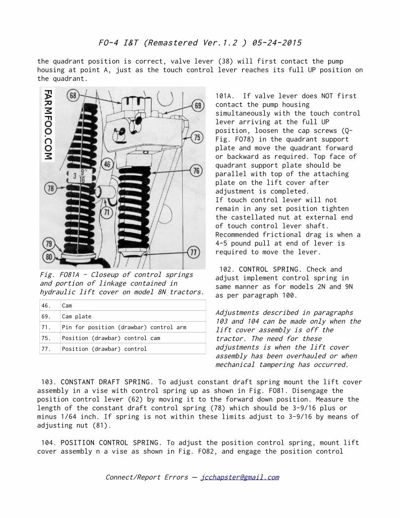
FO-4 I&T (Remastered Ver.1.2 ) 05-24-2015
the quadrant position is correct, valve lever (38) will first contact the pump housing at point A, just as the touch control lever reaches its full UP position on the quadrant.
101A. If valve lever does NOT first contact the pump housing simultaneously with the touch control lever arriving at the full UP position, loosen the cap screws (Q-Fig. FO78) in the quadrant support plate and move the quadrant forward or backward as required. Top face of quadrant support plate should be parallel with top of the attaching plate on the lift cover after adjustment is completed. If touch control lever will not remain in any set position tighten the castellated nut at external end of touch control lever shaft. Recommended frictional drag is when a 4-5 pound pull at end of lever is required to move the lever.
102. CONTROL SPRING. Check and adjust implement control spring in same manner as for models 2N and 9N as per paragraph 100.
Adjustments described in paragraphs 103 and 104 can be made only when the lift cover assembly is off the tractor. The need for these adjustments is when the lift cover assembly has been overhauled or when mechanical tampering has occurred.
103. CONSTANT DRAFT SPRING. To adjust constant draft spring mount the lift cover assembly in a vise with control spring up as shown in Fig. FO81. Disengage the position control lever (62) by moving it to the forward down position. Measure the length of the constant draft control spring (78) which should be 3-9/16 plus or minus 1/64 inch. If spring is not within these limits adjust to 3-9/16 by means of adjusting nut (81).
104. POSITION CONTROL SPRING. To adjust the position control spring, mount lift cover assembly n a vise as shown in Fig. FO82, and engage the position control
Connect/Report Errors – [email protected]
Fig. FO81A - Closeup of control springs and portion of linkage contained in hydraulic lift cover on model 8N tractors.
46. Cam
69. Cam plate
71. Pin for position (drawbar) control arm
75. Position (drawbar) control cam
77. Position (drawbar) control
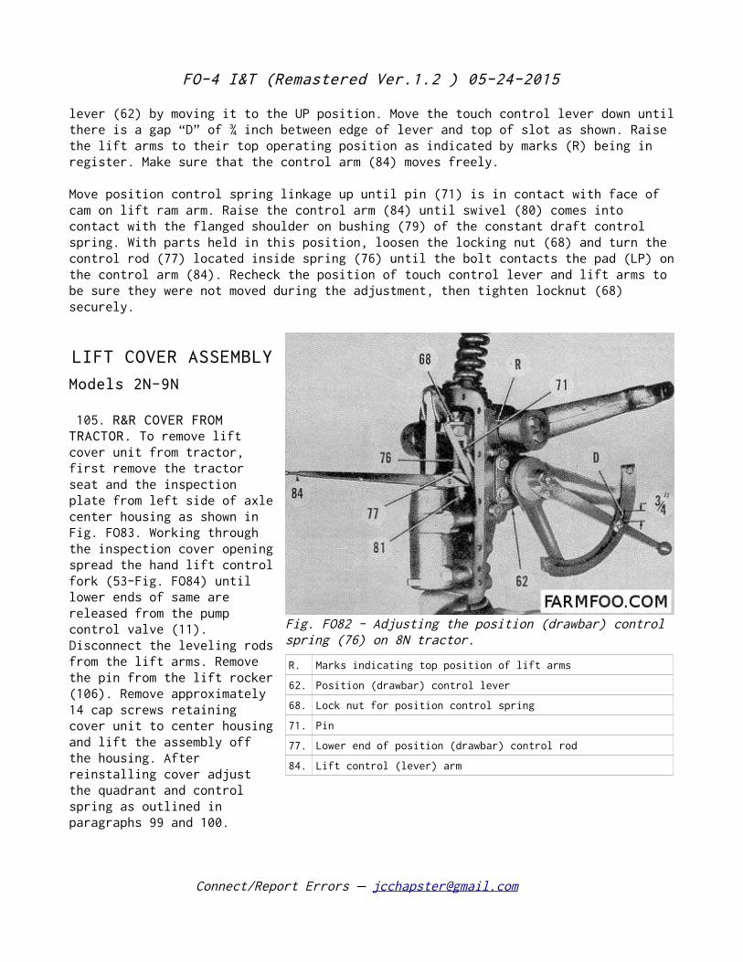
FO-4 I&T (Remastered Ver.1.2 ) 05-24-2015
lever (62) by moving it to the UP position. Move the touch control lever down until there is a gap “D” of ¾ inch between edge of lever and top of slot as shown. Raise the lift arms to their top operating position as indicated by marks (R) being in register. Make sure that the control arm (84) moves freely.
Move position control spring linkage up until pin (71) is in contact with face of cam on lift ram arm. Raise the control arm (84) until swivel (80) comes into contact with the flanged shoulder on bushing (79) of the constant draft control spring. With parts held in this position, loosen the locking nut (68) and turn the control rod (77) located inside spring (76) until the bolt contacts the pad (LP) on the control arm (84). Recheck the position of touch control lever and lift arms to be sure they were not moved during the adjustment, then tighten locknut (68) securely.
LIFT COVER ASSEMBLY
Models 2N-9N
105. R&R COVER FROM TRACTOR. To remove lift cover unit from tractor, first remove the tractor seat and the inspection plate from left side of axle center housing as shown in Fig. FO83. Working through the inspection cover opening spread the hand lift control fork (53-Fig. FO84) until lower ends of same are released from the pump control valve (11). Disconnect the leveling rods from the lift arms. Remove the pin from the lift rocker (106). Remove approximately 14 cap screws retaining cover unit to center housing and lift the assembly off the housing. After reinstalling cover adjust the quadrant and control spring as outlined in paragraphs 99 and 100.
Connect/Report Errors – [email protected]
Fig. FO82 - Adjusting the position (drawbar) control spring (76) on 8N tractor.
R. Marks indicating top position of lift arms
62. Position (drawbar) control lever
68. Lock nut for position control spring
71. Pin
77. Lower end of position (drawbar) control rod
84. Lift control (lever) arm
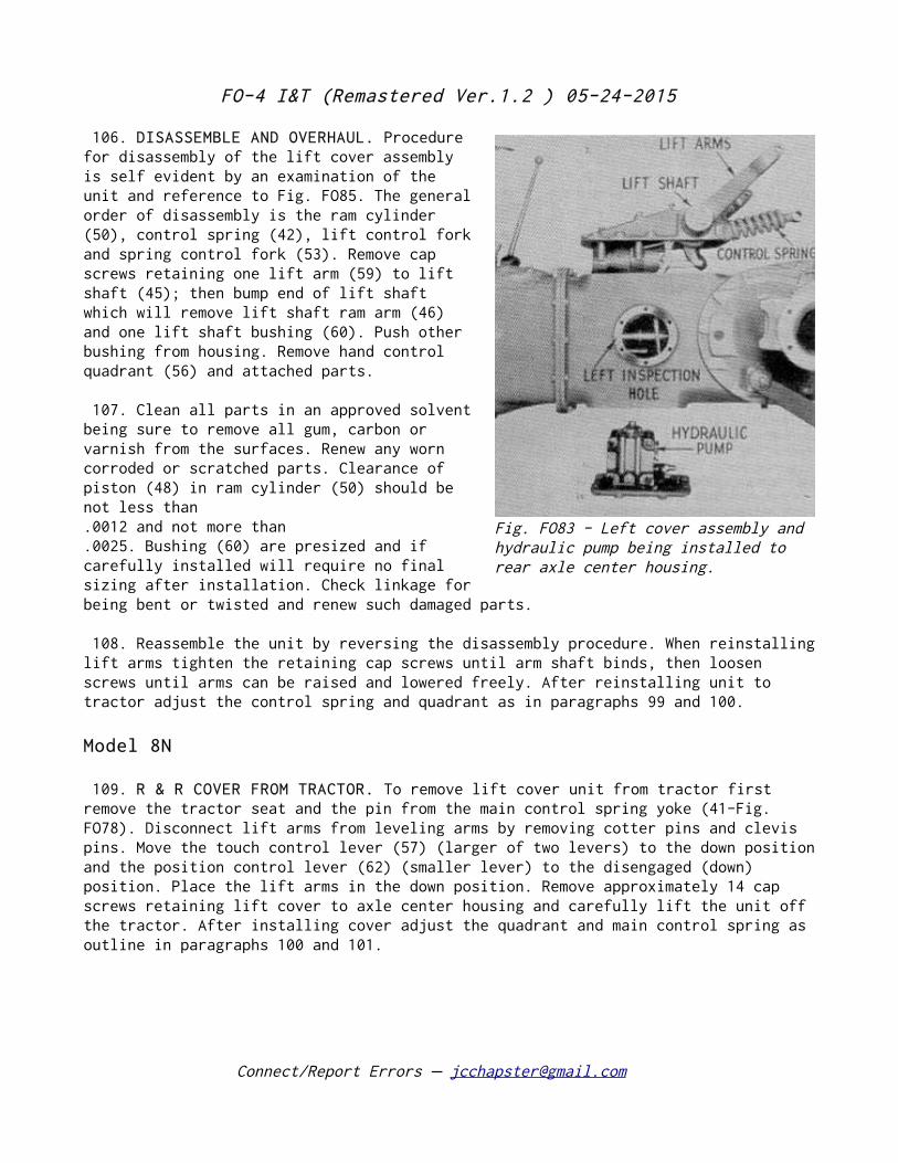
FO-4 I&T (Remastered Ver.1.2 ) 05-24-2015
106. DISASSEMBLE AND OVERHAUL. Procedure for disassembly of the lift cover assembly is self evident by an examination of the unit and reference to Fig. FO85. The general order of disassembly is the ram cylinder (50), control spring (42), lift control fork and spring control fork (53). Remove cap screws retaining one lift arm (59) to lift shaft (45); then bump end of lift shaft which will remove lift shaft ram arm (46) and one lift shaft bushing (60). Push other bushing from housing. Remove hand control quadrant (56) and attached parts.
107. Clean all parts in an approved solvent being sure to remove all gum, carbon or varnish from the surfaces. Renew any worn corroded or scratched parts. Clearance of piston (48) in ram cylinder (50) should be not less than .0012 and not more than .0025. Bushing (60) are presized and if carefully installed will require no final sizing after installation. Check linkage for being bent or twisted and renew such damaged parts.
108. Reassemble the unit by reversing the disassembly procedure. When reinstalling lift arms tighten the retaining cap screws until arm shaft binds, then loosen screws until arms can be raised and lowered freely. After reinstalling unit to tractor adjust the control spring and quadrant as in paragraphs 99 and 100.
Model 8N
109. R & R COVER FROM TRACTOR. To remove lift cover unit from tractor first remove the tractor seat and the pin from the main control spring yoke (41-Fig. FO78). Disconnect lift arms from leveling arms by removing cotter pins and clevis pins. Move the touch control lever (57) (larger of two levers) to the down position and the position control lever (62) (smaller lever) to the disengaged (down) position. Place the lift arms in the down position. Remove approximately 14 cap screws retaining lift cover to axle center housing and carefully lift the unit off the tractor. After installing cover adjust the quadrant and main control spring as outline in paragraphs 100 and 101.
Connect/Report Errors – [email protected]
Fig. FO83 - Left cover assembly and hydraulic pump being installed to rear axle center housing.
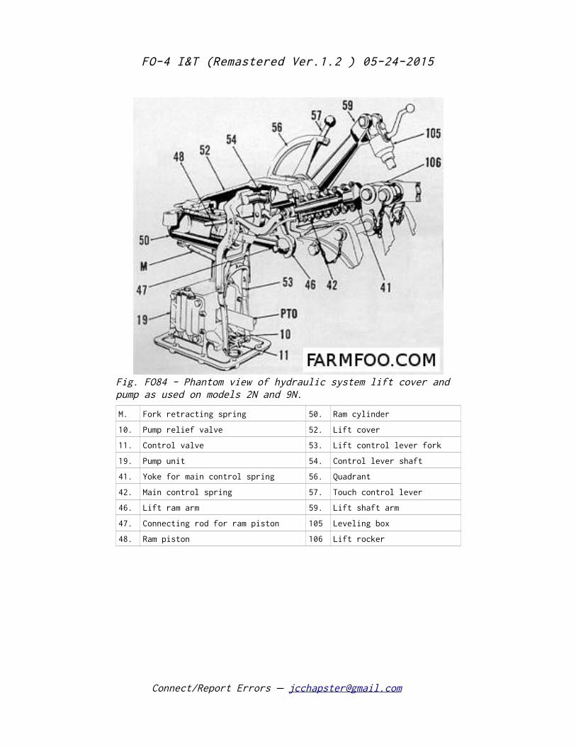
FO-4 I&T (Remastered Ver.1.2 ) 05-24-2015
Connect/Report Errors – [email protected]
Fig. FO84 - Phantom view of hydraulic system lift cover and pump as used on models 2N and 9N.
M. Fork retracting spring 50. Ram cylinder
10. Pump relief valve 52. Lift cover
11. Control valve 53. Lift control lever fork
19. Pump unit 54. Control lever shaft
41. Yoke for main control spring 56. Quadrant
42. Main control spring 57. Touch control lever
46. Lift ram arm 59. Lift shaft arm
47. Connecting rod for ram piston 105 Leveling box
48. Ram piston 106 Lift rocker
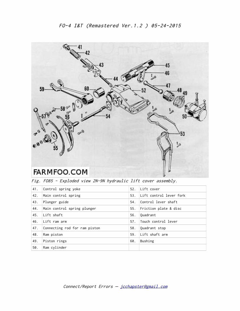
FO-4 I&T (Remastered Ver.1.2 ) 05-24-2015
Connect/Report Errors – [email protected]
Fig. FO85 - Exploded view 2N-9N hydraulic lift cover assembly.
41. Control spring yoke 52. Lift cover
42. Main control spring 53. Lift control lever fork
43. Plunger guide 54. Control lever shaft
44. Main control spring plunger 55. Friction plate & disc
45. Lift shaft 56. Quadrant
46. Lift ram arm 57. Touch control lever
47. Connecting rod for ram piston 58. Quadrant stop
48. Ram piston 59. Lift shaft arm
49. Piston rings 60. Bushing
50. Ram cylinder
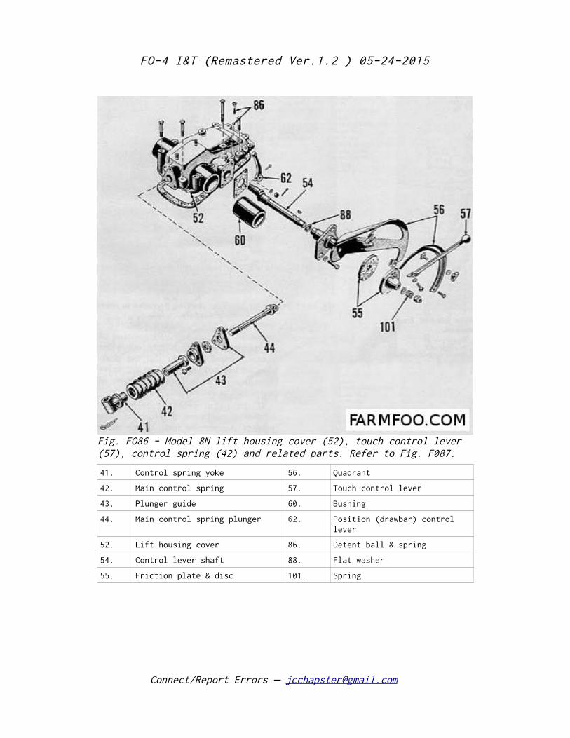
FO-4 I&T (Remastered Ver.1.2 ) 05-24-2015
Connect/Report Errors – [email protected]
Fig. FO86 - Model 8N lift housing cover (52), touch control lever (57), control spring (42) and related parts. Refer to Fig. F087.
41. Control spring yoke 56. Quadrant
42. Main control spring 57. Touch control lever
43. Plunger guide 60. Bushing
44. Main control spring plunger 62. Position (drawbar) control lever
52. Lift housing cover 86. Detent ball & spring
54. Control lever shaft 88. Flat washer
55. Friction plate & disc 101. Spring
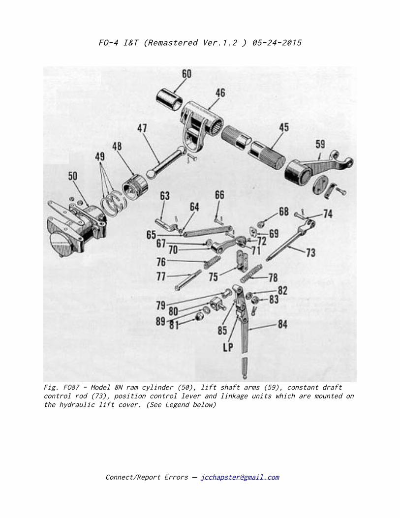
FO-4 I&T (Remastered Ver.1.2 ) 05-24-2015
Connect/Report Errors – [email protected]
Fig. FO87 - Model 8N ram cylinder (50), lift shaft arms (59), constant draft control rod (73), position control lever and linkage units which are mounted on the hydraulic lift cover. (See Legend below)
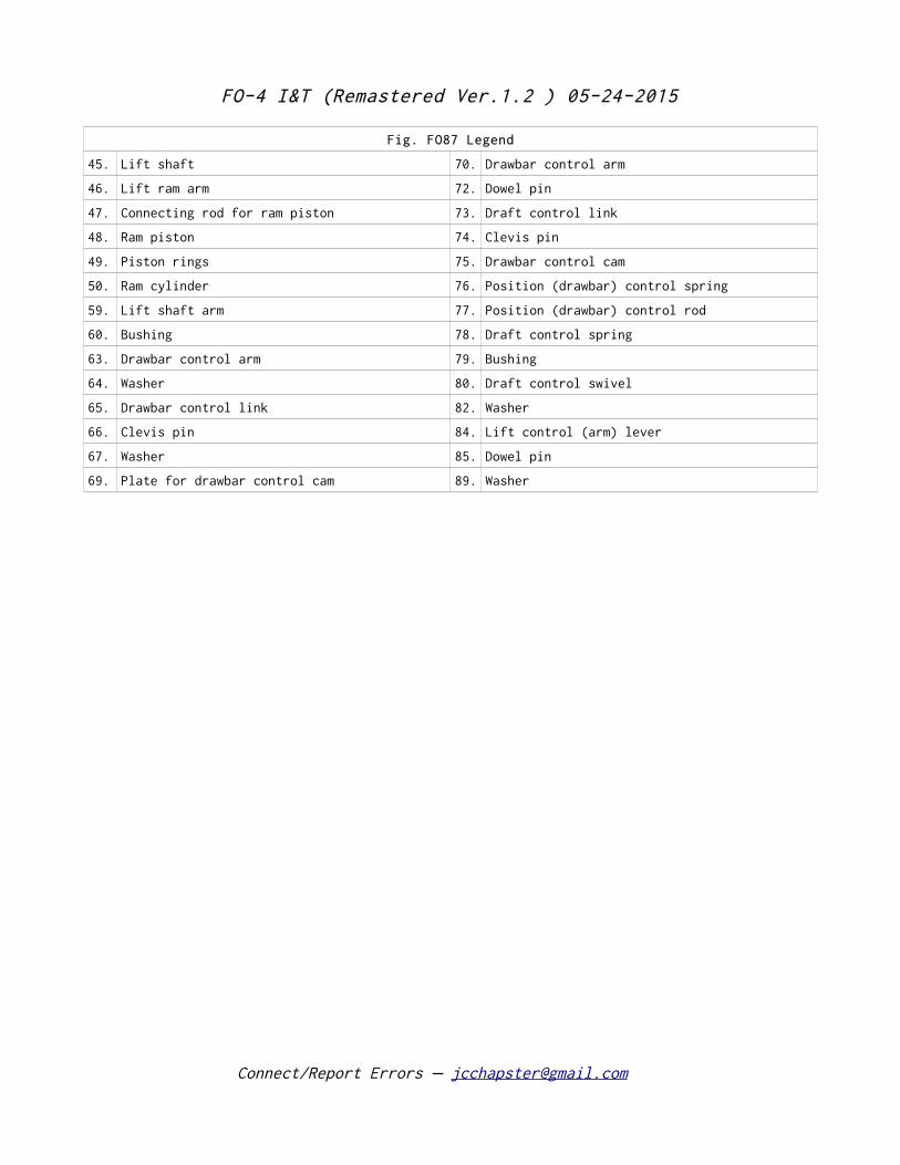
FO-4 I&T (Remastered Ver.1.2 ) 05-24-2015
Fig. FO87 Legend
45. Lift shaft 70. Drawbar control arm
46. Lift ram arm 72. Dowel pin
47. Connecting rod for ram piston 73. Draft control link
48. Ram piston 74. Clevis pin
49. Piston rings 75. Drawbar control cam
50. Ram cylinder 76. Position (drawbar) control spring
59. Lift shaft arm 77. Position (drawbar) control rod
60. Bushing 78. Draft control spring
63. Drawbar control arm 79. Bushing
64. Washer 80. Draft control swivel
65. Drawbar control link 82. Washer
66. Clevis pin 84. Lift control (arm) lever
67. Washer 85. Dowel pin
69. Plate for drawbar control cam 89. Washer
Connect/Report Errors – [email protected]
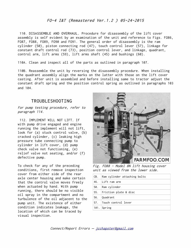
FO-4 I&T (Remastered Ver.1.2 ) 05-24-2015
110. DISASSEMBLE AND OVERHAUL. Procedure for disassembly of the lift cover assembly is self evident by an examination of the unit and reference to Figs. FO86, FO87, FO88, FO89, FO90 and FO91. The general order of disassembly is the ram cylinder (50), piston connecting rod (47), touch control lever (57), linkage for constant draft control rod (73), position control lever, and linkage, quadrant, control arm, lift arms (59), lift arms shaft (45) and bushings (60).
110A. Clean and inspect all of the parts as outlined in paragraph 107.
110B. Reassemble the unit by reversing the disassembly procedure. When installing the quadrant assembly align the marks on the latter with those on the lift cover casting. After unit is assembled and before installing same to tractor adjust the constant draft spring and the position control spring as outlined in paragraphs 103 and 104.
TROUBLESHOOTING For pump testing procedure, refer to paragraph 114.
112. IMPLEMENT WILL NOT LIFT. If with pump drive engaged and engine running the implement will not lift, look for (a) stuck control valve, (b) cracked cylinder, (c) leaking high pressure tube connecting pump to cylinder in lift cover, (d) pump check valve not functioning, (e) relief valve not seating, and/or (f) defective pump.
To check for any of the preceding conditions, first remove inspection cover from either side of the rear axle center housing and make certain that the control valve moves freely when actuated by hand. With pump running, there should be no visible oil spray in the compartment and no turbulence of the oil adjacent to the pump unit. The existence of either condition indicates leakage, the location of which can be traced by visual inspection.
Connect/Report Errors – [email protected]
Fig. FO88 - Model 8N lift housing cover unit as viewed from the lower side.
CB. Ram cylinder attaching bolts
46. Lift ram arm
50. Ram cylinder
55. Friction plate & disc
56. Quadrant
57. Touch control lever
101. Spring
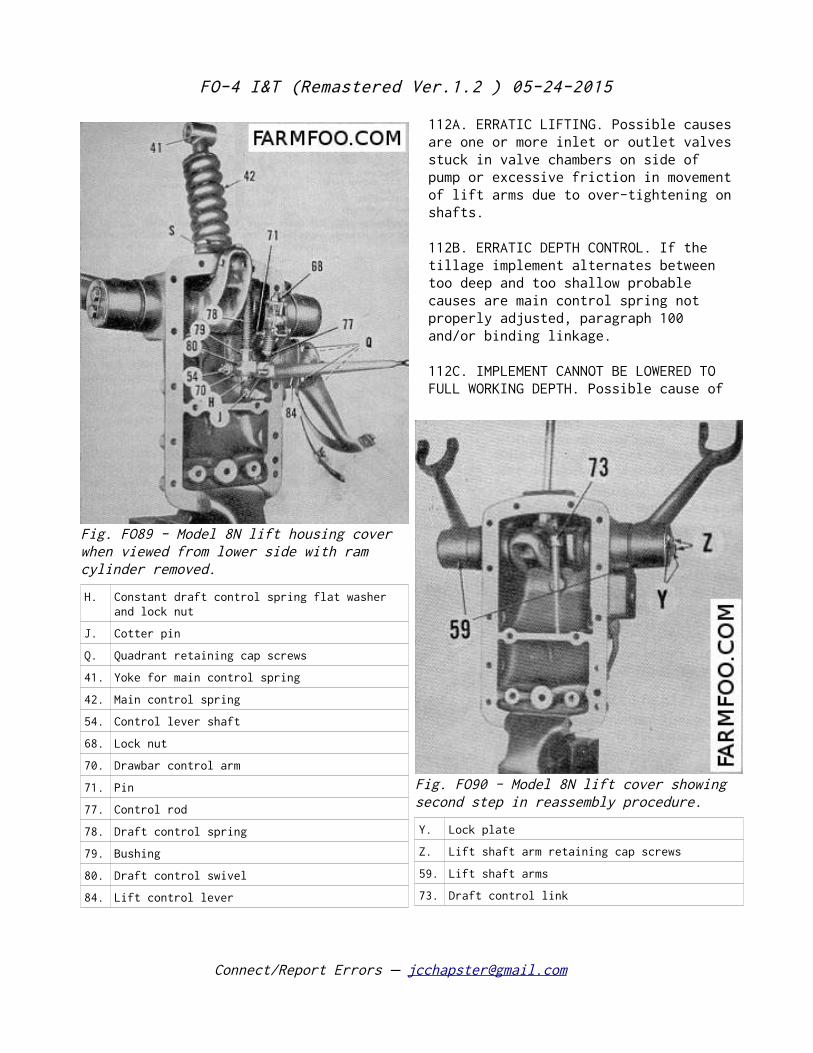
FO-4 I&T (Remastered Ver.1.2 ) 05-24-2015
112A. ERRATIC LIFTING. Possible causes are one or more inlet or outlet valves stuck in valve chambers on side of pump or excessive friction in movement of lift arms due to over-tightening on shafts.
112B. ERRATIC DEPTH CONTROL. If the tillage implement alternates between too deep and too shallow probable causes are main control spring not properly adjusted, paragraph 100 and/or binding linkage.
112C. IMPLEMENT CANNOT BE LOWERED TO FULL WORKING DEPTH. Possible cause of
Connect/Report Errors – [email protected]
Fig. FO89 - Model 8N lift housing cover when viewed from lower side with ram cylinder removed.
H. Constant draft control spring flat washer and lock nut
J. Cotter pin
Q. Quadrant retaining cap screws
41. Yoke for main control spring
42. Main control spring
54. Control lever shaft
68. Lock nut
70. Drawbar control arm
71. Pin
77. Control rod
78. Draft control spring
79. Bushing
80. Draft control swivel
84. Lift control lever
Fig. FO90 - Model 8N lift cover showing second step in reassembly procedure.
Y. Lock plate
Z. Lift shaft arm retaining cap screws
59. Lift shaft arms
73. Draft control link
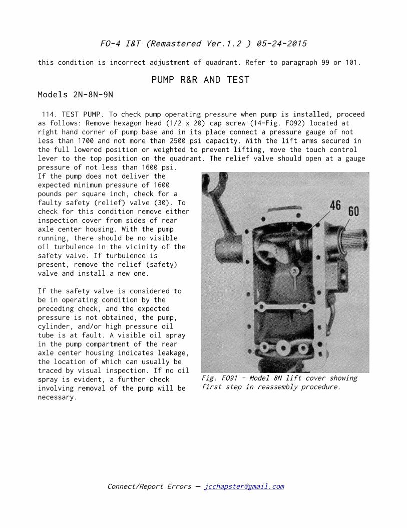
FO-4 I&T (Remastered Ver.1.2 ) 05-24-2015
this condition is incorrect adjustment of quadrant. Refer to paragraph 99 or 101.
PUMP R&R AND TEST
Models 2N-8N-9N
114. TEST PUMP. To check pump operating pressure when pump is installed, proceed as follows: Remove hexagon head (1/2 x 20) cap screw (14-Fig. FO92) located at right hand corner of pump base and in its place connect a pressure gauge of not less than 1700 and not more than 2500 psi capacity. With the lift arms secured in the full lowered position or weighted to prevent lifting, move the touch control lever to the top position on the quadrant. The relief valve should open at a gauge pressure of not less than 1600 psi. If the pump does not deliver the expected minimum pressure of 1600 pounds per square inch, check for a faulty safety (relief) valve (30). To check for this condition remove either inspection cover from sides of rear axle center housing. With the pump running, there should be no visible oil turbulence in the vicinity of the safety valve. If turbulence is present, remove the relief (safety) valve and install a new one.
If the safety valve is considered to be in operating condition by the preceding check, and the expected pressure is not obtained, the pump, cylinder, and/or high pressure oil tube is at fault. A visible oil spray in the pump compartment of the rear axle center housing indicates leakage, the location of which can usually be traced by visual inspection. If no oil spray is evident, a further check involving removal of the pump will be necessary.
Connect/Report Errors – [email protected]
Fig. FO91 - Model 8N lift cover showing first step in reassembly procedure.
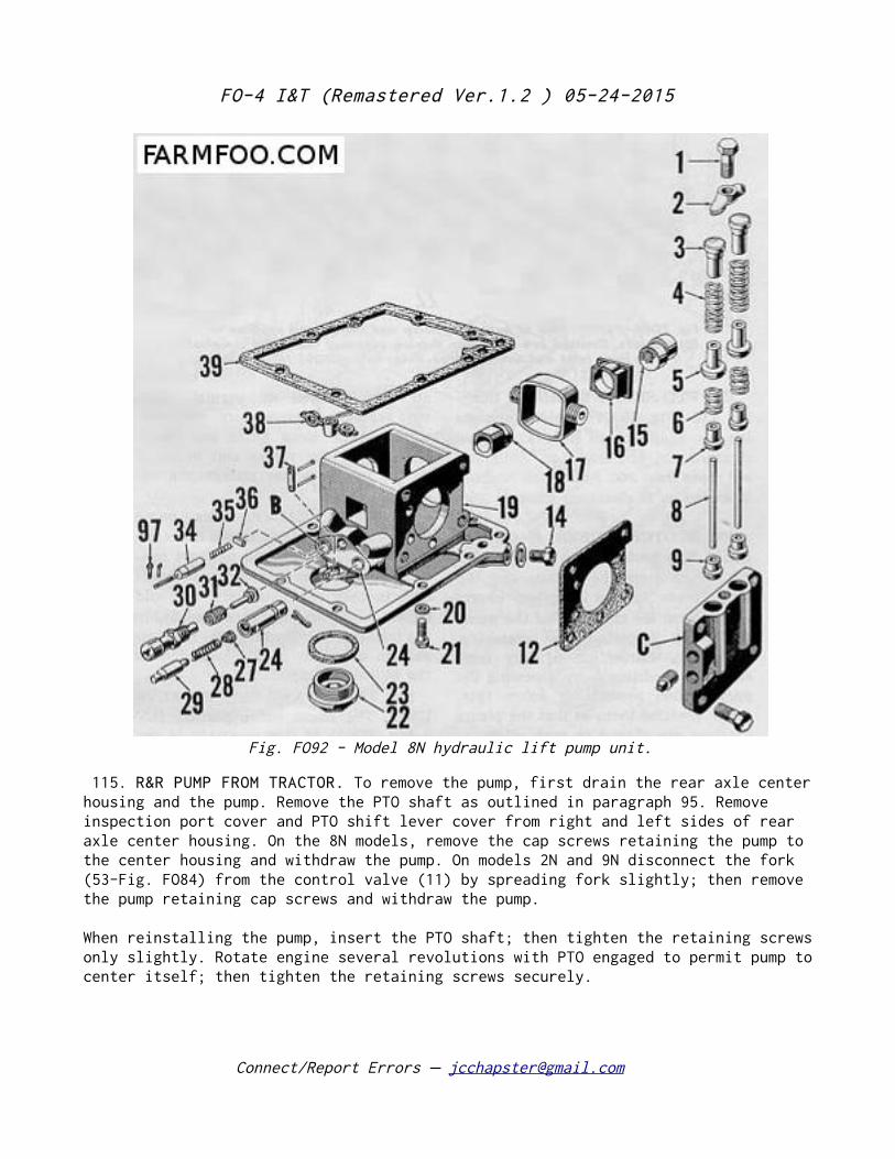
FO-4 I&T (Remastered Ver.1.2 ) 05-24-2015
115. R&R PUMP FROM TRACTOR. To remove the pump, first drain the rear axle center housing and the pump. Remove the PTO shaft as outlined in paragraph 95. Remove inspection port cover and PTO shift lever cover from right and left sides of rear axle center housing. On the 8N models, remove the cap screws retaining the pump to the center housing and withdraw the pump. On models 2N and 9N disconnect the fork (53-Fig. FO84) from the control valve (11) by spreading fork slightly; then remove the pump retaining cap screws and withdraw the pump.
When reinstalling the pump, insert the PTO shaft; then tighten the retaining screws only slightly. Rotate engine several revolutions with PTO engaged to permit pump to center itself; then tighten the retaining screws securely.
Connect/Report Errors – [email protected]
Fig. FO92 - Model 8N hydraulic lift pump unit.
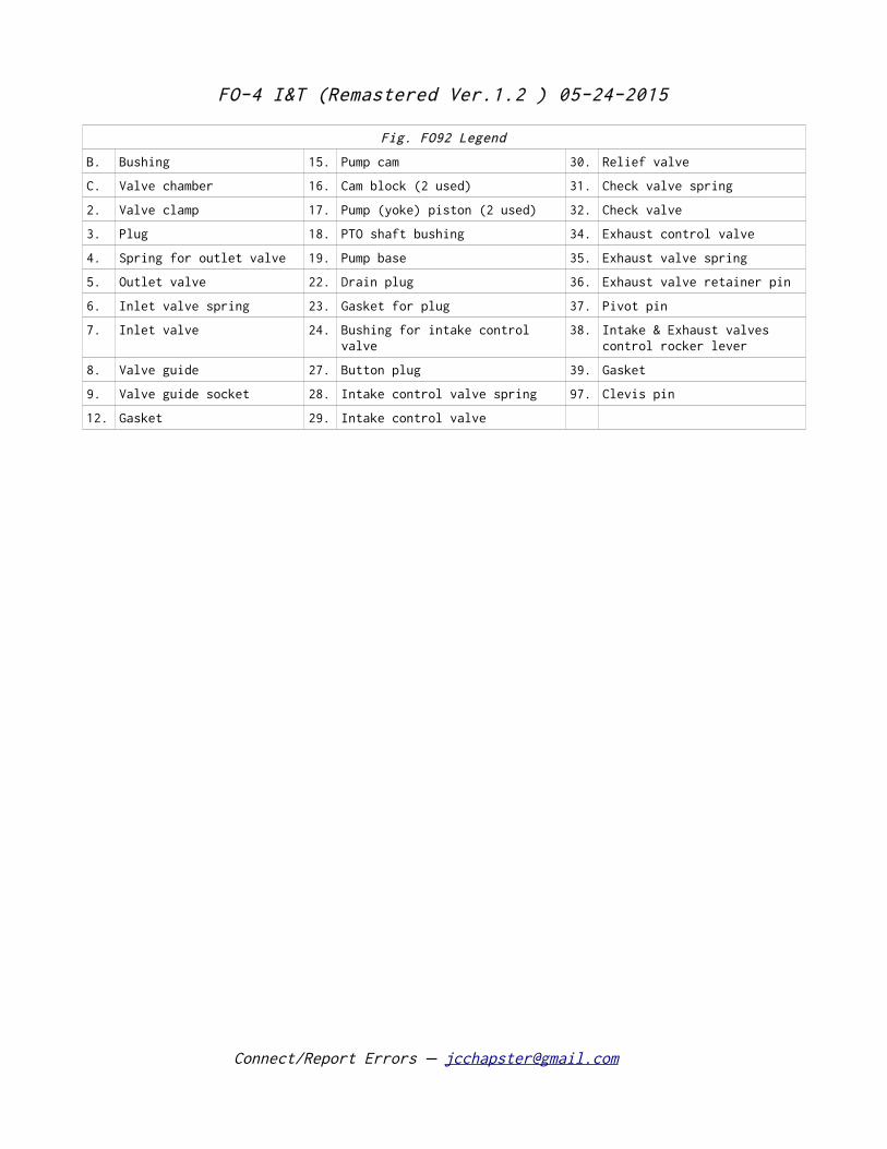
FO-4 I&T (Remastered Ver.1.2 ) 05-24-2015
Fig. FO92 Legend
B. Bushing 15. Pump cam 30. Relief valve
C. Valve chamber 16. Cam block (2 used) 31. Check valve spring
2. Valve clamp 17. Pump (yoke) piston (2 used) 32. Check valve
3. Plug 18. PTO shaft bushing 34. Exhaust control valve
4. Spring for outlet valve 19. Pump base 35. Exhaust valve spring
5. Outlet valve 22. Drain plug 36. Exhaust valve retainer pin
6. Inlet valve spring 23. Gasket for plug 37. Pivot pin
7. Inlet valve 24. Bushing for intake control valve
38. Intake & Exhaust valves control rocker lever
8. Valve guide 27. Button plug 39. Gasket
9. Valve guide socket 28. Intake control valve spring 97. Clevis pin
12. Gasket 29. Intake control valve
Connect/Report Errors – [email protected]
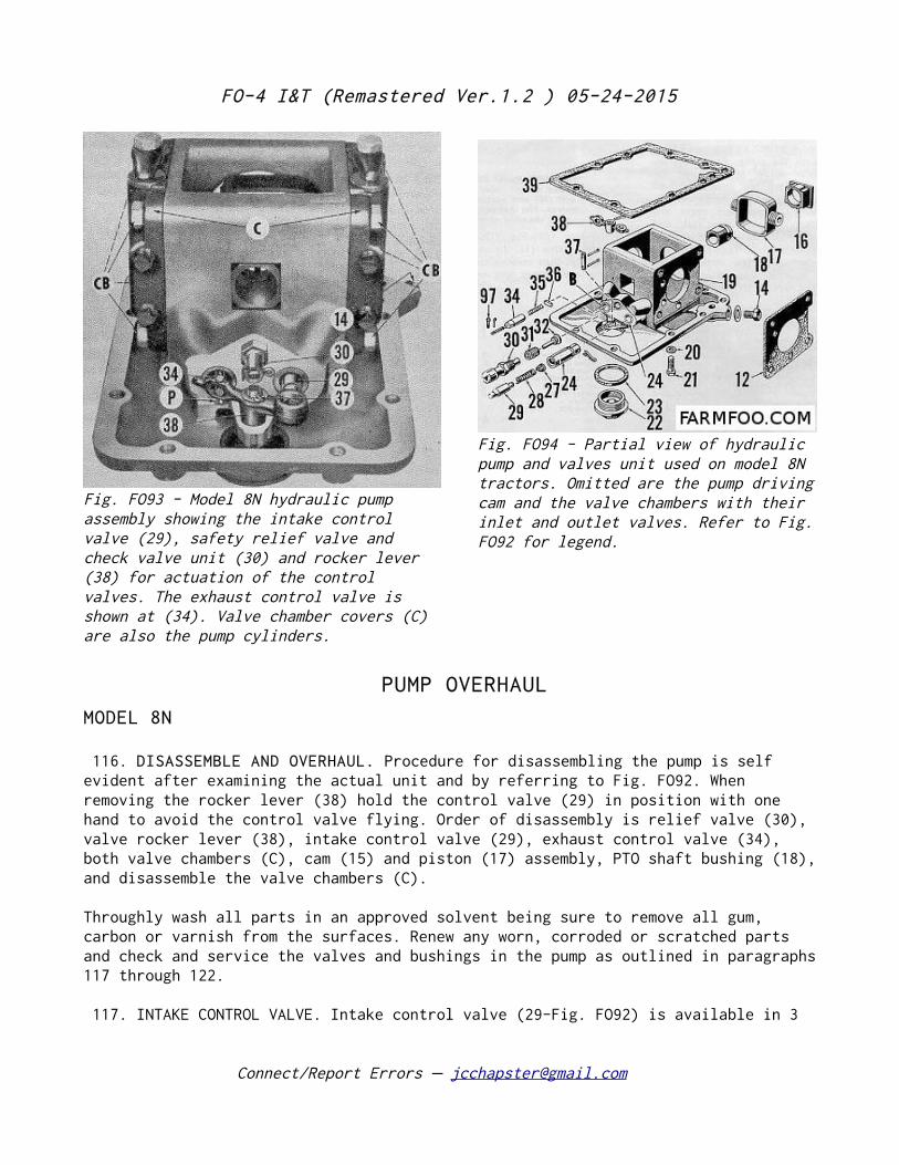
FO-4 I&T (Remastered Ver.1.2 ) 05-24-2015
PUMP OVERHAUL
MODEL 8N
116. DISASSEMBLE AND OVERHAUL. Procedure for disassembling the pump is self evident after examining the actual unit and by referring to Fig. FO92. When removing the rocker lever (38) hold the control valve (29) in position with one hand to avoid the control valve flying. Order of disassembly is relief valve (30), valve rocker lever (38), intake control valve (29), exhaust control valve (34), both valve chambers (C), cam (15) and piston (17) assembly, PTO shaft bushing (18), and disassemble the valve chambers (C).
Throughly wash all parts in an approved solvent being sure to remove all gum, carbon or varnish from the surfaces. Renew any worn, corroded or scratched parts and check and service the valves and bushings in the pump as outlined in paragraphs 117 through 122.
117. INTAKE CONTROL VALVE. Intake control valve (29-Fig. FO92) is available in 3
Connect/Report Errors – [email protected]
Fig. FO93 - Model 8N hydraulic pump assembly showing the intake control valve (29), safety relief valve and check valve unit (30) and rocker lever (38) for actuation of the control valves. The exhaust control valve is shown at (34). Valve chamber covers (C) are also the pump cylinders.
Fig. FO94 - Partial view of hydraulic pump and valves unit used on model 8N tractors. Omitted are the pump driving cam and the valve chambers with their inlet and outlet valves. Refer to Fig. FO92 for legend.
FO-4 I&T (Remastered Ver.1.2 ) 05-24-2015
diameters to permit obtaining a free but minimum-clearance-fit of the valve in the bushing (24). When checking the fit, valve and the bushing should be coated with hydraulic oil which is the same lubricant used in the transmission. Obtain minimum clearance by selection from the available valves: Part No. Diameter Color 8N698E .5917-.5918 White 8N698F .5918-.5920 Blue 8N698G .5920-.5921 Yellow
Valve bushing is available in standard bore size only but can be obtained .010 oversize on the outside diameter. Be sure to use latest bushing which has 4 intake holes. Bushing should not be sized after installation and should be pressed in flush with the face of the pump base. Turn bushing to position where cotter pin hole is approximately horizontal so as to facilitate insertion of the locking cotter pin.
118. EXHAUST CONTROL VALVE. Exhaust control valve (34-Fig. FO94) and its bushings (B) in the pump base should be free of scratches. Valve should move freely in bushing but should have minimum clearance when checked with the recommended transmission oil on the valve and bushing. Exhaust valve is available in 5 diameters as follows:
Part No. Diameter Color 8N640A2 .5917-.5918 White 8N640B .5919-.5920 Blue 8N640C .5920-.5921 Yellow 8N640D .5923-.5924 Green 8N640E .5925-.5926 Orange
Bushing (B) for exhaust control valve is pressed into pump base and should be renewed if scratched or otherwise damaged. Bushing should not be sized after installation. It should be installed flush with face of pump base and with holes in such position as to assure easy insertion of the locking cotter pin. Bore diameter of bushing is .5926.
119. SAFETY AND CHECK VALVE UNIT. A check valve (32-Fig. FO94) is combined with the safety (relief) valve (30) mounted in the pump base. The safety valve is factory adjusted to unseat at a minimum pressure of 1600 psi. if any parts of this valve are worn or broken or show signs of leakage, install a new valve unit.
Inspect the check valve for signs of leakage. Improper seating may be due to irregularities of the seat in the pump base which can be corrected by using the special Ford reseating tool or equivalent as shown in Fig. FO96. Leakage signs on the valve (32-Fig. FO94) can be corrected by renewal of the valve, followed by lapping if necessary.
Connect/Report Errors – [email protected]
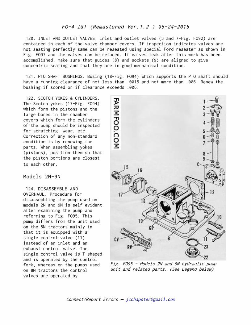
FO-4 I&T (Remastered Ver.1.2 ) 05-24-2015
120. INLET AND OUTLET VALVES. Inlet and outlet valves (5 and 7-Fig. FO92) are contained in each of the valve chamber covers. If inspection indicates valves are not seating perfectly same can be reseated using special Ford reseater as shown in Fig. FO97 and the valves can be refaced. If valves leak after this work has been accomplished, make sure that guides (8) and sockets (9) are aligned to give concentric seating and that they are in good mechanical condition.
121. PTO SHAFT BUSHINGS. Busing (18-Fig. FO94) which supports the PTO shaft should have a running clearance of not less than .0015 and not more than .006. Renew the bushing if scored or if clearance exceeds .006.
122. SCOTCH YOKES & CYLINDERS. The Scotch yokes (17-Fig. FO94) which form the pistons and the large bores in the chamber covers which form the cylinders of the pump should be inspected for scratching, wear, etc. Correction of any non-standard condition is by renewing the parts. When assembling yokes (pistons), position them so that the piston portions are closest to each other.
Models 2N-9N
124. DISASSEMBLE AND OVERHAUL. Procedure for disassembling the pump used on models 2N and 9N is self evident after examining the pump and referring to Fig. FO95. This pump differs from the unit used on the 8N tractors mainly in that it is equipped with a single control valve (11) instead of an inlet and an exhaust control valve. The single control valve is T shaped and is operated by the control fork, whereas on the pumps used on 8N tractors the control valves are operated by
Connect/Report Errors – [email protected]
Fig. FO95 - Models 2N and 9N hydraulic pump unit and related parts. (See Legend below)
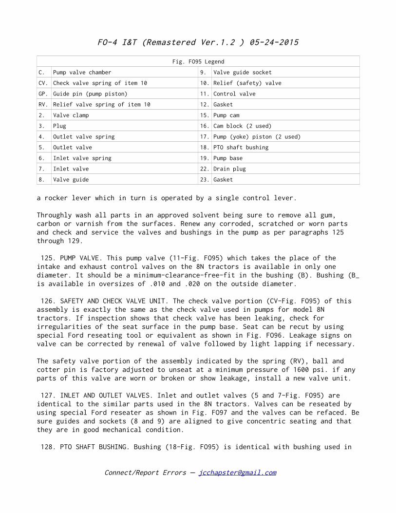
FO-4 I&T (Remastered Ver.1.2 ) 05-24-2015
Fig. FO95 Legend
C. Pump valve chamber 9. Valve guide socket
CV. Check valve spring of item 10 10. Relief (safety) valve
GP. Guide pin (pump piston) 11. Control valve
RV. Relief valve spring of item 10 12. Gasket
2. Valve clamp 15. Pump cam
3. Plug 16. Cam block (2 used)
4. Outlet valve spring 17. Pump (yoke) piston (2 used)
5. Outlet valve 18. PTO shaft bushing
6. Inlet valve spring 19. Pump base
7. Inlet valve 22. Drain plug
8. Valve guide 23. Gasket
a rocker lever which in turn is operated by a single control lever. Throughly wash all parts in an approved solvent being sure to remove all gum, carbon or varnish from the surfaces. Renew any corroded, scratched or worn parts and check and service the valves and bushings in the pump as per paragraphs 125 through 129.
125. PUMP VALVE. This pump valve (11-Fig. FO95) which takes the place of the intake and exhaust control valves on the 8N tractors is available in only one diameter. It should be a minimum-clearance-free-fit in the bushing (B). Bushing (B_ is available in oversizes of .010 and .020 on the outside diameter.
126. SAFETY AND CHECK VALVE UNIT. The check valve portion (CV-Fig. FO95) of this assembly is exactly the same as the check valve used in pumps for model 8N tractors. If inspection shows that check valve has been leaking, check for irregularities of the seat surface in the pump base. Seat can be recut by using special Ford reseating tool or equivalent as shown in Fig. FO96. Leakage signs on valve can be corrected by renewal of valve followed by light lapping if necessary.
The safety valve portion of the assembly indicated by the spring (RV), ball and cotter pin is factory adjusted to unseat at a minimum pressure of 1600 psi. if any parts of this valve are worn or broken or show leakage, install a new valve unit.
127. INLET AND OUTLET VALVES. Inlet and outlet valves (5 and 7-Fig. FO95) are identical to the similar parts used in the 8N tractors. Valves can be reseated by using special Ford reseater as shown in Fig. FO97 and the valves can be refaced. Be sure guides and sockets (8 and 9) are aligned to give concentric seating and that they are in good mechanical condition.
128. PTO SHAFT BUSHING. Bushing (18-Fig. FO95) is identical with bushing used in
Connect/Report Errors – [email protected]
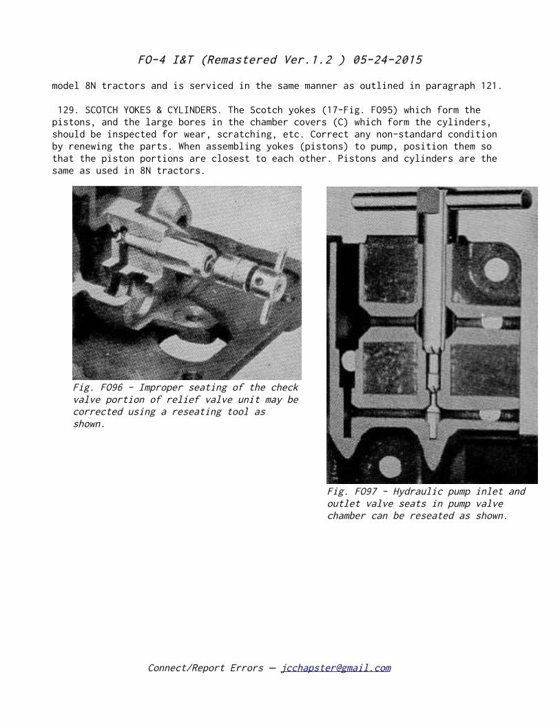
FO-4 I&T (Remastered Ver.1.2 ) 05-24-2015
model 8N tractors and is serviced in the same manner as outlined in paragraph 121.
129. SCOTCH YOKES & CYLINDERS. The Scotch yokes (17-Fig. FO95) which form the pistons, and the large bores in the chamber covers (C) which form the cylinders, should be inspected for wear, scratching, etc. Correct any non-standard condition by renewing the parts. When assembling yokes (pistons) to pump, position them so that the piston portions are closest to each other. Pistons and cylinders are the same as used in 8N tractors.
Connect/Report Errors – [email protected]
Fig. FO96 - Improper seating of the check valve portion of relief valve unit may be corrected using a reseating tool as shown.
Fig. FO97 - Hydraulic pump inlet and outlet valve seats in pump valve chamber can be reseated as shown.