Temperature Dependence of Aliovalent-Vanadium Doping in LiFePO 4 Cathodes
Upload
yaconrootmaxaboutCategory
view
0download
0
Electrochimica Acta 157 (2015) 351–358
Fabrication of sulfur cathodes by wet-powder spraying and theunderstanding of degradation
Natalia A. Cañas a,*, Ana L.P. Baltazar a,1, Micael A.P. Morais a,1, T.Oliver Freitag a,N. Wagner a,2, K.Andreas Friedrich a,b
a Institute of Engineering Thermodynamics, German Aerospace Center, Stuttgart, Germanyb Institute for Thermodynamic and Thermal Engineering, University of Stuttgart, Germany
A R T I C L E I N F O
Article history:Received 9 September 2014Received in revised form 22 December 2014Accepted 2 January 2015Available online 3 January 2015
Keywords:Lithiumsulfurbatteriessprayingdegradation
A B S T R A C T
In this work, wet powder spraying is presented as an alternative method for the fabrication ofsulfur/carbon composite cathodes. The high dispersion and homogeneity of the cathode layer result inhigh capacity Li/S batteries. Additional use of LiNO3 as additive improved the discharge capacity to800 Ah kgS�1, 400 Ah kgcathode�1 (at 0.18 C) and 410 Ah kgS�1, 205 Ah kgcathode�1 (at 2 C) after 50 cycles. Theshuttle mechanism is reduced and a coulombic efficiency of around 100% is reached and maintainedconstant until 1000 cycles. To understand more the degradation mechanisms of the battery,Thermogravimetry combined with gas analysis (TG/MS) as well X-ray diffraction (operando andmappings) were applied. The formation of an amorphous phase during cycling that remains nearly stablein the later cycles is considered to be one of the main factors affecting capacity decay. Moreover, othersprocesses are identified as contributors of battery degradation like PVDF decomposition, structuralchanges of carbon black, and reduction of sulfur content on the bulk of the electrode. These new insightson the degradation processes may contribute to the further understanding, selection of materials, andimprovement of this battery.
ã 2015 Elsevier Ltd. All rights reserved.
Contents lists available at ScienceDirect
Electrochimica Acta
journa l home page : www.e l sev ier .com/ loca te /e le cta cta
1. Introduction
Li/S batteries present many advantages including a hightheoretical capacity (1675 Ah kg�1), high energy density (2500 Whkg�1), and low cost of sulfur. However, degradation of the batterycomponents at high number of cycles and high discharge rates isstill a problem. The development of components and fabricationprocesses applicable at large-scale production and at low cost isalso a great challenge for the commercialization of Li/S batteries.
Most attempts to improve the electrochemical performance ofLi/S batteries have been focused on the positive electrode [1–4].Due to the low electrical conductivity of sulfur, the incorporation ofa conductive material in the cathode of Li/S batteries is one of themain issues related to the fabrication of the electrode. Differentstrategies were developed associated to the selection of theconductive material and the method of incorporating sulfur in the
* Corresponding author at: Institute of Engineering Thermodynamics, GermaAerospace Center, Stuttgart, Germany.Tel.: +49 711 6862 576; fax: +49 0711 6862 474.
E-mail addresses: [email protected], [email protected] (N.A. Cañas).1 These authors contributed equally to this work.2 Electrochemical Society Active Member.
http://dx.doi.org/10.1016/j.electacta.2015.01.0020013-4686/ã 2015 Elsevier Ltd. All rights reserved.
composite. Carbon black [5–12], active carbon [13,14] carbonnanotubes [5], and graphene [15,16] are common conductivematerials applied in Li/S batteries. The sulfur composite isprepared by mechanical mixing/milling of both components, bymelting or sublimation of sulfur, or by in situ reaction of sulfur.These last strategies facilitate the incorporation of sulfur in nanomaterials. The incorporation of sulfur in a nano-porous conductivematrix was first presented by Wang and coworkers [13,14]. Thepore size was around 2.5 nm and resulted in batteries with areversible capacity of 400 Ah kgS�1 (current density: 0.3 mA cm�2,max. 25 cycles). Ji and coworkers [17] obtained better cyclabilitywith the utilization of high order meso-porous carbon; 6.5 nmdiameter carbon tubes separated by 3–4 nm wide channel voids.This configuration should help to trap the polysulfides andfacilitate the conduction of ions and electrons in the matrix.Reversible capacity of 1005 Ah gS�1 was achieved (current density:0.37 mA cm�2, max. 20 cycles). Further attempts were made usingthe same approach to encapsulate sulfur in an conductive matrix,among others: [18–21].
Li/S batteries fabricated by Wang and coworkers [22] achieveddischarge capacities of 800 Ah kgS�1 up to 400 cycles at a dischargerate of 0.2 C. They created hollow carbonized polypyrrole spheresof around 450 nm diameter, in which melted sulfur was embedded.

352 N.A. Cañas et al. / Electrochimica Acta 157 (2015) 351–358
Stable capacities (�400 Ah kg�1) at 2 C were demonstrated by Fuet al. using a sulfur polypyrrole composite cathode [23]. Highcycling performance until now were demonstrated by Seh andcolleagues [3]. They generated a TiO2 yolk shell with internal voidto encapsulate sulfur and retain intermediate products. Thisconfiguration showed capacity retention of 67 % after 1000 cycles.
In this work, we present developments related with thefabrication of industrially-oriented cathodes, the main factorsaffecting the battery capacity, and new insights into the degrada-tion processes of the Li/S battery. Wet powder spraying techniqueis presented as an alternative method to doctor blade that can beapplied successful for the fabrication of sulfur/carbon compositeselectrodes. Moreover, the degradation of sulfur/carbon compositescathodes are studied with a) X-ray diffraction for detectionand quantification of crystalline and amorphous products andb) Thermogravimetry coupled with mass spectroscopy (TG/MS) tostudy the degradation of components and prove the morphologicalchanges on the cathode.
2. Experimental
2.1. Cathode preparation
The cathode were composed of 50 wt.% sulfur powder(S, 99.5% purity, Alfa Aesar), 40 wt.% Super P carbon black(CB, 99% purity, Alfa Aesar) as conductive material, and 10 wt.%polyvinylidene fluoride (PVDF, Alfa Aesar) as binder. PVDF wasdissolved separately in a 50/50 vol.% mixture of DMSO andethanol. Ethanol was added to facilitate the transport of thecathode suspension in the spraying machine and for rapidevaporation after coating.
Two different cathodes are compared in this work accordingwith the fabrication steps summarized in Table A.1. The maindifferences were: (a) Cathode I was prepared by mixing thepowder components in a roll mixer and afterward the solventswere added. The suspension was sprayed using an internalnozzle and coated in one step, while the substrate was placed ina heating plate at 100 �C. (b) Cathode II was prepared by mixingS and CB in a tumbling mixer at higher velocity and by addinglater the PVDF dissolved in DMSO/Ethanol. The coating processwas carried out in three steps; between each spraying, thecathode was dried in an oven at 60 �C. The reduction oftemperature avoided the formation of cracks in the layer due torapid drying. Spraying in three steps, by addition of drying stepsbetween each coating, improved the stability of the cathode andthe adherence on the aluminum, and the homogeneity of thelayers (Cathode II).
The thickness of the cathode layer, without substrate, variedbetween 15–20 mm. The sulfur loading was 0.45 mg cm�2 anddensity of the cathode layer was �0.51 g cm�3. These values canbe increased by raising the sulfur content in the composite.Moreover, the thickness of the electrode can be increasedaccording with demand by inclusion of furthers spraying/dryingsteps. However, the electrode thickness is limited by thediffusional resistance or loss of adhesion of the active layer withthe substrate. Lower sulfur utilization is observed in Li/Sbatteries for sulfur cathodes with increasing cathode thicknessor sulfur loading [24]; and the formation of discharge andcharge products may be concentrated at the surface of theelectrode. The use of protective and stabilizer layers may benecessary to avoid high capacity decay due to the highercontent of low conductive sulfur [25–27]. Here, we arepresenting the wet powder spraying method for coating ofsulfur/carbon composites. Nevertheless, improvements on thecapacity stability and increase in the total specific energy arestill part of the ongoing work.
Using a wet powder spraying machine, the cathodesuspension was applied onto a substrate with pressurized air.The suspension was placed in a pressurized tank and it wasdirected to the nozzle inside a polypropylene tube. Anair-atomizing external mixing nozzle (LECHLER GmbH) wasused for this purpose, and the slurry mixes with the air outsidethe nozzle. The movement of the nozzle as well as the sampleholder was controlled by a 3D axis robot (Janome JR 2400 NGLT). The axis with the nozzle moves in perpendicular direction(y) to the substrate holder at 300 mm s�1, while the substrateholder advances step by step in x-direction so all the surface ofthe substrate is coated. The pressure of air and suspension, aswell the distance between nozzle and layer, were adjusted toobtain a uniform spraying. Homogenous layers were obtainedby injecting the suspension at low pressures (between0.2–0.4 bar) and atomizing externally with air at 0.5 barpressure. The distance between nozzle and substrate was setat z = 180 mm.
After drying the cathode were punched out for cell preparationin individual cathodes of 10 and 16 mm diameter.
2.2. Cell construction and electrochemical testing
The battery was built and tested in a so-called Swagelok1 cellto assure the hermetic sealing and to avoid reaction of the batterycomponents with air according to the procedures previouslypublished [28,29]. Cathodes of 10 and 16 mm diameter were tested.The volume of electrolyte was maintained constant for all testedcells (14 and 36 mL for small and large cells respectively) as well asthe concentration of LiPF6 (1 M) in TEGDME. Electrolytes withdifferent LiNO3 concentration (0, 0.1, 0.5, 0.75, and 1 M) (99.99%,Sigma–Aldrich) were prepared in the glove box under Aratmosphere using a magnetic stirrer for at least 24 hr. A0.75 mm thick lithium foil (99.9%, Sigma–Aldrich) was used asanode, and Celgard1 2500 as separator.
The electrochemical testing or cycling of the batteries wascarried out with a cell test system (BaSyTec) [30]. The charge-discharge proceeded galvanostatically at 300 A kgsulfur�1 (0.18 C).The battery was first discharged until 1.5 V, charged at constantcurrent density up to 2.8 V, and then a potentiostatic periodfollowed for 15 min before starting the next cycle.
2.3. Characterization procedures
Samples were measured in a simultaneous thermal analysis(STA) equipment (Netzsch, STA 449 C Jupiter1) coupled with amass spectrometer (MS) (Netzsch, MS403C). A plate crucible madeof Al2O3 (Tmax = 1700 �C), with a diameter of 17 mm, was chosen formeasuring the samples in order to place the 16 mm diametercathodes over it without being cut. The samples were heated from25 �C until 1000 �C at a constant heating rate of 5 K min�1. The gasused for the experiments was a 20:80 mixture of O2/N2. The gasesgenerated during heating were analyzed in line with the massspectrometer. First, the cathode components: carbon black (CB),polyvinylidene fluoride (PVDF) and sulfur (S) were analyzedseparately and second, the cathodes before and after cycling weremeasured after drying.
X-ray diffractograms were recorded using an x-ray diffracto-meter (D8 Discover Bruker GADDS) with a VÅNTEC-2000 detector.The spectra were taken on reflection mode using a tunedmonochromatic and parallel x-ray beam (Cu-Ka). The acceleratingvoltage was 45 kV and the tube current was 0.650 mA. An XRDmapping was measured using the raster grid schematically shownin Fig. 7(a). The cathode was measured in 13 positions and duringthe measurement the sample stage oscillated in 0.5 mm XY toobtain higher statistic information of the sample.

N.A. Cañas et al. / Electrochimica Acta 157 (2015) 351–358 353
3. Results and discussion
3.1. Influence of cathode fabrication on the capacity fading
High resolution SEM pictures show that the uses of differentfabrication procedures result in dissimilar cathode morpholo-gies (Fig. A.1). Cathode I presents larger particle size (up to ca.20 mm) than Cathode II. Moreover, no homogenous particle sizeis obtained in Cathode I, probably because of the agglomerationof S crystallites due to soft mixing produced by the roll mixer.On the other hand, the tumbling mixer reduces the sulfurparticle to less than 4 mm, and only some larger particles arepresent. Moreover, Cathode II has a surface completely coveredby CB particles. Some CB particles seem to be embedded in thesulfur and some wrapped around the sulfur. The CB networkand the close contact between the conductive carbon and sulfurare responsible for providing electron pathways for theinsulating sulfur. In case of Cathode I, the uncovered area ofsulfur particle is higher.
Fig. 1 shows the discharge capacity vs. cycle number forCathode I and Cathode II with the electroltyte: 1 M LiPF6 inTEGDME. The discharge capacity is based on the mass of sulfurpresent in the battery. Batteries fabricated with Cathode II havea higher discharge capacity, in the first cycle 1150 Ah kgS�1
compared to 850 Ah kgS�1 for Cathode I. The reversible dischargecapacity after 50 cycles remains at 528 Ah kgS�1 while for Cathode Iis 275 Ah kgS�1, this represents 32% and 47% capacity retentionrespectively. The Coulombic efficiency is in both cases not stableduring cycling with values lower than 100%. The high values of theerror bars demonstrate the instability of the batteries due to thecharge process. The improved dispersion of S particles, the highcontact with carbon black network, as well as the reduction of Sparticle size, are responsible for the increase in the dischargecapacity of batteries fabricated with Cathode II. This is related to ahigher active surface area which enhances sulfur dissolution andutilization for the electrochemical reactions. Nevertheless, bothsystems display similar capacity retention. This means that thereduction of particle size and increase of particle dispersioninfluence positively the utilization of the active material in the firstcycles but it does not avoid the capacity fading of the batteries.
The shuttle effect is observed during charge and originates anincrease of the charge capacity that varies from cell to cell (seedischarge curves Fig. A.4). The large errors bars shown in Fig. 1(b)are the result of the difference in charge capacity. On the one hand,Li2S is oxidized in the cathode generating long-chain lithiumpolysulfides and elemental sulfur step by step. On the other hand,
Fig. 1. Cyclability of batteries using Cathode I and Cathode II at 0.18 C-rate. (a) Dischargecells were tested for each type of cathode. The average and error bars are calculated b
polysulfides are reduced chemically on the lithium surface. Whenthe concentration of long-chain lithium polysulfides increases, theshuttle phenomenon is enhanced. Thus, at the high plateau(�2.5 V) two processes would be in competition: the electro-chemical oxidation of polysulfide on the cathode surface andthe chemical reduction of polysulfide on the anode. The activeshuttle phenomenon prolonged consequently the charge process,which reduce the cycling performance of the batteries
3.2. Influence of LiNO3 as co-salt for the electrolyte
In 2008, Mikhaylik [31] studied the influence of lithium imidein a 50:50 ratio mixture of 1,3-dioxolane (DOL) and dimethoxy-ethane (DME) as well as in a solution of trifluoromethyl sulfonate.He postulated that N—O chemical bond was the responsible forinhibition of the shuttle mechanism. To demonstrate this; hetested salts containing the N—O bond like potassium nitrate,cesium nitrate, ammonium nitrate, potassium nitrite, and dinitro-toluene. The highest Coulombic efficiency and discharge capacityupon cycling were achieved with LiNO3 concentrations between0.2 M and 1.0 M. After this, several studies have shown the benefitsof LiNO3 [32–36]. This additive or co-salt avoids large chargingcycles, increasing the Coulombic efficiency to around 100%. This isattributed to elimination of the shuttle mechanisms due to theformation of a “protective” and Li+ ion conductive layer on theanode surface. This layer is composed of LixNOy and/or LixSOy
components [37] which prevents the reaction of polysulfides withlithium metal and thus it eliminates the shuttle effect duringcharge.
In this section, LiNO3 is used as a co-salt in 1 M LiPF6 TEGDMEelectrolyte to stabilize the Coulombic efficiency and to increase thecyclability of the Li/S battery. The results of the electrochemicaltests for different concentrations of LiNO3 at 0.18C-rate aresummarized in Fig. 2.
The capacity fading is affected by the concentration of theco-salt and reaches a minimum of around 35% for 0.75 M LiNO3
(Fig. 2(a)). By further increase of concentration the capacity fadingrises again. This last behavior may be explained by the formation ofa thicker protective layer on the anode, which reduces the mobilityof Li+, and thus its availability for further reactions. Although theCoulombic efficiency reaches already values near to 100% with0.1 M LiNO3, by increasing the concentration the Coulombicefficiency is more stable (lower error bars, Fig. 2(b)). Consideringboth the capacity fading and the Coulombic efficiency, the optimalconcentration of LiNO3 is found to be 0.75 M for this cellconfiguration.
capacity vs cycle. (b) Coulombic efficiency. Electrolyte: 1 M LiPF6 in TEGDME. Threeased on the results of 3 tested batteries.

Fig. 2. Influence of concentration of LiNO3 in the capacity fading of batteries after 50 cycles (a) and the Coulombic efficiency (b), tested at 0.18 C rate. *Capacity fading wascalculated between cycle 1 and 50. The average and error bars are calculated based on the results of 3 tested batteries.
Fig. 3. Improvements on the cyclability of the cell by modification of cathode andelectrolyte. Tests were performed at 0.18 C-rate. The average and error bars arecalculated based on the results of 3 tested batteries.
354 N.A. Cañas et al. / Electrochimica Acta 157 (2015) 351–358
To summarize, the improvements on capacity regardingcathode fabrication (Cathode I ! Cathode II) and electrolytemodification (Cathode II without ! with 0.75 M LiNO3) arepresented in Fig. 3. The reduction of sulfur particle size and itshomogenous distribution in the cathode layer influence mainly theinitial discharge capacity (852 Ah kgS�1 for Cathode I,1127 Ah kgS�1
for Cathode II). The co-salt reduces the shuttle mechanismwhich is reflected by the lower capacity fading and thus a highercapacity at the 50th cycle (527 Ah kgS�1 Cathode II without LiNO3,
800 Ah kgS�1 with 0.75 M LiNO3).Fig. 4(a) shows the performance of the battery (Cathode II,
Electrolyte: 0.75 M LiNO3, 1 M LiPF6 in TEGDME) when dischargingat 0.18 C and 2 C up to 1000 cycles. As expected, the initial values ofcapacity are much lower for higher 2 C-rate. However, the chargecapacity increases in the first cycles reaching it maximum at the13th cycle. An explanation for this must be the lower dissolution ofsulfur at the initial stages of discharge and lower crystallization ofLi2S at the end of discharge. The discharge reaction mechanismincludes first the dissolution of sulfur in the electrolyte and secondthe reaction with Li ions to build up the polysulfides; when thedischarge rate is fast, sulfur cannot dissolve completely and lowerformation of polysulfides is reached. Moreover, the crystallizationof Li2S is a lower process and this must favored after several cycleswhen polysulfides have been accumulated in the electrolyte.
The Coulombic efficiency maintains constant at values near to100%, for both C-rates, confirming that the protective effect of
LiNO3 against the shuttle mechanisms prevails up to 1000 cycles.Some investigations have shown that the effect of LiNO3
disappears at higher cycle number[34]; however, this is notobserved in the cell tested through this work. The difference oncapacity for cathode II (Figs. 4 and 5), with electrolyte: 0.75 MLiNO3, 1 M LiPF6 in TEGDME, tested at 0.18 C is caused by adifference of sulfur loading (�30%) because they were coated indifferent production lots. The standard deviation (average of thefirst 50 cycles) between both production lots was 59 Ah kgS�1.
After 500 cycles both capacity curves meets and the capacityfading comes independent of the discharge rate. It is expected thatinactive cores of S8 or Li2S are built up, and lower the utilization ofactive material in the subsequent cycles. Moreover, according withthe similar discharge profile observed in Fig. 4(b), the reactionmechanisms at different C-rates seems to be similar after500 cycles. The first discharge plateau is shorter due to the loweramount of crystalline sulfur present in the charge state. Therefore,it is expected that most of the reactions occurs in the liquid phase;this means oxidation and reduction of polysulfides with lessformation of S8 or Li2S. The average energy density of the cellcalculated based on the total mass of cathode, is presented for cycle1 and 1000 in Fig. 4(c).
3.3. Sulfur distribution and structural changes on the cathode
In previous work, we presented in situ XRD analysis of Li/Sbatteries [38]. It was demonstrated for the first time the formationof Li2S during discharge during the first cycles. Moreover, therecrystallization of sulfur was also proved at the end of charge withan orientation of sulfur crystallites perpendicular to cathodesurface. During charge, the reaction of Li2S is slower comparedwith the recrystallization rate of sulfur. By the second discharge,almost 50% less crystalline Li2S is formed compared with the firstdischarge. At the end of the second charge, the peaks of sulfurappear at the same positions, indicating a similar orientation of theparticles as the one after the first charge. The formation of theamorphous phase which was not published provides importantin-sight into the sulfur formation. For this reason, we evaluatenow the amorphization of the cathode to complete the previousanalysis [38].
A single line fitting for the amorphous phase combined with arefinement of the crystalline phase was performed. The back-ground was fitted with a 1st order function and the amorphousphase with a single Split-PseudoVoigt function (spv) located at themaximum of the amorphous bump. The results show the changes

Fig. 4. (a) Discharge capacity and Coulombic efficiency of Li/S batteries at 0.18 C and 2 C. The red inset in the picture shows an example of the variation of the capacity causedby changes in the environmental temperature during testing. (b) Comparison of discharge profile between batteries tested at 0.18 C and 2 C. (c) Specific energy density basedon the cathode mass for cycle 1 and 1000. Test show the results of one cell.
Fig. 5. Semi-quantitative X-ray analysis for the first two discharges (a, c) and charge cycles (b, d) of a Li/S battery.
N.A. Cañas et al. / Electrochimica Acta 157 (2015) 351–358 355
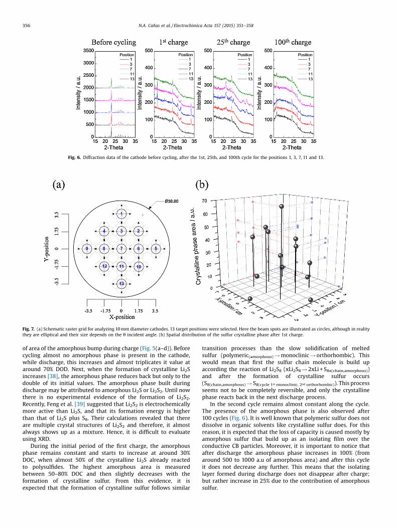
Fig. 6. Diffraction data of the cathode before cycling, after the 1st, 25th, and 100th cycle for the positions 1, 3, 7, 11 and 13.
Fig. 7. (a) Schematic raster grid for analyzing 10 mm diameter cathodes. 13 target positions were selected. Here the beam spots are illustrated as circles, although in realitythey are elliptical and their size depends on the u incident angle. (b) Spatial distribution of the sulfur crystalline phase after 1st charge.
356 N.A. Cañas et al. / Electrochimica Acta 157 (2015) 351–358
of area of the amorphous bump during charge (Fig. 5(a–d)). Beforecycling almost no amorphous phase is present in the cathode,while discharge, this increases and almost triplicates it value ataround 70% DOD. Next, when the formation of crystalline Li2Sincreases [38], the amorphous phase reduces back but only to thedouble of its initial values. The amorphous phase built duringdischarge may be attributed to amorphous Li2S or Li2S2. Until nowthere is no experimental evidence of the formation of Li2S2.Recently, Feng et al. [39] suggested that Li2S2 is electrochemicallymore active than Li2S, and that its formation energy is higherthan that of Li2S plus S8. Their calculations revealed that thereare multiple crystal structures of Li2S2 and therefore, it almostalways shows up as a mixture. Hence, it is difficult to evaluateusing XRD.
During the initial period of the first charge, the amorphousphase remains constant and starts to increase at around 30%DOC, when almost 50% of the crystalline Li2S already reactedto polysulfides. The highest amorphous area is measuredbetween 50–80% DOC and then slightly decreases with theformation of crystalline sulfur. From this evidence, it isexpected that the formation of crystalline sulfur follows similar
transition processes than the slow solidification of meltedsulfur (polymeric(amorphous)! monoclinic ! orthorhombic). Thiswould mean that first the sulfur chain molecule is build upaccording the reaction of Li2S8 (xLi2S8! 2xLi + S8x(chain,amorphous))and after the formation of crystalline sulfur occurs(S8(chain,amorphous)! S8(cycle 1st monoclinic, 2nd orthorhombic)). This processseems not to be completely reversible, and only the crystallinephase reacts back in the next discharge process.
In the second cycle remains almost constant along the cycle.The presence of the amorphous phase is also observed after100 cycles (Fig. 6). It is well known that polymeric sulfur does notdissolve in organic solvents like crystalline sulfur does. For thisreason, it is expected that the loss of capacity is caused mostly byamorphous sulfur that build up as an isolating film over theconductive CB particles. Moreover, it is important to notice thatafter discharge the amorphous phase increases in 100% (fromaround 500 to 1000 a.u of amorphous area) and after this cycleit does not decrease any further. This means that the isolatinglayer formed during discharge does not disappear after charge;but rather increase in 25% due to the contribution of amorphoussulfur.

Fig. 8. TG before cycling and after 1, 10, 50 and 100 cycles with the evolved gasanalysis of SO2, F, and CO2.
Table 1Changes in oxidation temperature of cathode components.
Material Oxidation temperature (�C) Oxidation range (�C)
Before cycling After cycling Before cycling After cycling
Sulfur(SO2)
219 130 146 97
PVDF 378 – 126 –
CB (CO2) 660 469 170 98
N.A. Cañas et al. / Electrochimica Acta 157 (2015) 351–358 357
Fig. 6 illustrates the results of the XRD measurement atdifferent positions in the cathode (according to Fig. 8). Beforecycling, the cathode shows a homogenous dispersion of sulfur,this is illustrated for the raster positions 1, 3, 7, 11, and 13. Thisimplies that through the selected mixing procedure the cathodecomponents are well mixed and that the coating proceduregenerates cathode with uniform thickness. In contrast, cathodeafter cycling show an inhomogeneous distribution of sulfur whichis reflected by changes in the intensity of the reflections. Moreover,variation in the position of the peaks reveals changes of theorientation of the sulfur crystallites with the position.
In Fig. 7 the integrated area of the sulfur reflexes arerepresented in the 13 positions of cathode II after the 1st cycle.The distribution of sulfur is inhomogeneous and the highestamount is located in the center of the cathode, in the side positionsalmost no crystalline sulfur was measured. The inhomogeneousdistribution of sulfur in the cathode after cycling has been alsoseen using light microscopy (Fig. A.2–A3).
3.4. Stability of binding
TG curves of the cathode before cycling are shown in Fig. 8. Allthe measurements were carried out under air atmosphere to detectCB and PVDF up to 800 �C and repeated for three samples. The firstmass loss at 150 �C is related to sulfur oxidation, the slight decreaseat around 400 �C to PDVF degradation, and at around 650 �C theoxidation of the carbon black particles occurs. TG/DSC diagrams ofthe cathode components can be found in Fig. A.6, A.7 and Table A.2.The oxidation temperature of transformation is in all cases lowerthan the characteristic temperature obtained for the componentsmeasured separately as a powder. This is explained by the fact thatoxidation reactions occur at a slower rate in the cathode due to thebinding between particles.
TG curves for cathodes after 1, 10, 50, and 100 cycles areillustrated in Fig. 8. As a complementary analysis to TG, the gasevolved during heating of sample was investigated with MS. Theevolution of the mass number 64 (SO2), 44 (CO2), and 19 (F) isdisplayed in the curves. After cycling, the mass loss of sulfur occursat lower temperature, SO2 forms between 100–150 �C instead of250–300 �C (before cycling). The shift of the oxidation of sulfurfrom 219 �C before cycling to ca. 120 �C after cycling is explained bythe reduction of the crystallite size and structure after cycling,which increased the surface area of reaction. Furthermore, thecrystallization of sulfur on the surface of the cathode and not inthe bulk material may facilitate the reaction of sulfur with oxygen.The decrease in mass at around 120 �C for cathodes after cycling isrelated not only to the mass of sulfur, but also to reaction productsof electrolyte in air. This was proved by measuring a cathode afterdrying this with electrolyte (Fig. A.8). After cycling a decrease ofthe peak area for SO2 is observed, this is correlated with thecontent of sulfur in the cathode. The loss of active material iscaused by the incomplete reaction of polysulfides to sulfur duringcharge, as well by the loss of sulfur which deposits in the separatorsurface.
The TG peak of PVDF is not distinguishable anymore aftercycling. Moreover, the results of the MS reveals that the fluorinesignal detected at around 400 �C for the cathode before cycling canno longer be detected after cycling. This may be a result of thedecomposition of the binder by reaction with polysulfides duringcycling.
Before cycling, CB particles oxidizes first slowly (small shoulderat 600 �C) and then rapidly (sharp peak) at the temperature rangeof 600–700 �C. Contrary, oxidation occurs at 200 �C lower forcathodes after cycling (660 �C before cycling to 469 �C after cycling(Table 1). These results suggest that the structure of CB is affectedby the electrochemical cycling of the cathode; the binding of the CBparticles in the structure may be partially destroyed, and thisfacilitates the oxidation process shown by the low oxidationtemperatures in the TG measurements. In addition, the oxidationprocess after cycling occurs in some cases in several steps: seedouble peaks in MS of CB i.e. cycle 1 and 50. Nevertheless, theappearance of one or several peaks could not be attributed to aspecific cycle of the batterys life.

358 N.A. Cañas et al. / Electrochimica Acta 157 (2015) 351–358
4. Conclusions
The use of wet powder-spraying allows the fabrication ofhomogenous sulfur-composite layers. However, the use of largeamount of solvents is a disadvantage, and a solvent recuperationsystem should be implemented in case of industrial applications.Improvements on the mixing and milling processes showed thatwell-dispersed and small sulfur particles, surrounded by CBparticles, improves the sulfur utilization during the first cycles,which results in an increase of battery performance from 275 to528 Ah kgS�1 after 50 cycles. Nevertheless, the capacity fading of thebattery is still high (47%) and it is caused among others by the lowCoulombic efficiency generated by the shuttle mechanisms. This canbe improved by the utilization of LiNO3 as co-salt in the electrolyte.With this electrolyte additive and cell configuration dischargecapacities of 800 Ah kgS�1 were achieved (50 cycles, at 0.18 C-rate).Further studies will be focused in the protection of this cathode withprotective layers for the retention of active material [26,32,40–43].
The appearance of an amorphous phase is revealed duringcycling. The amount of this phase increases during the firstdischarge/charge and remains almost stable in the further cycles.This may be associated to the formation of amorphous S duringcharge and amorphous Li2S or Li2S2 during discharge. The change instructure of sulfur already shown using XRD, it is confirmed in the TGcurves: the formation of small crystallite or deposition of activematerial on the surface shift the oxidation process from 219 �C(before cycling) to 130 �C (after cycling). In addition, the loss of theTG-Peak of PVDF after cycling is attributed to its degradation andthis may affect the binding between the CB and S particles duringcycling. A drastically reduction of the oxidation temperature ofCB from 660 �C (before cycling) to 469 �C (after cycling) reveals thatthe conductive material is also altered by the electrochemicalcycling. This reduction may be explained by the destruction ofthe CB structure, which is important for the electron transport in thecell.
Appendix A. Supplementary data
Supplementary data associated with this article can befound, in the online version, at http://dx.doi.org/10.1016/j.electacta.2015.01.002.
References
[1] X. Ji, L.F. Nazar, Advances in Li–S batteries, J. Mater. Chem. 20 (2010) 9821.[2] A. Manthiram, Y. Fu, Y.-S. Su, Challenges and Prospects of Lithium-Sulfur
Batteries, Acc. Chem. Res. 46 (2012) 1125–1134.[3] Z. Wei Seh, W. Li, J.J. Cha, G. Zheng, Y. Yang, M.T. McDowell, et al., Sulphur–TiO2
yolk–shell nanoarchitecture with internal void space for long-cyclelithium–sulphur batteries, Nat. Commun. 4 (2013) 1331–1336.
[4] J. Xie, J. Yang, X. Zhou, Y. Zou, J. Tang, S. Wang, et al., Preparation ofthree-dimensional hybrid nanostructure-encapsulated sulfur cathode forhigh-rate lithium sulfur batteries, J. Power Sources 253 (2014) 55–63.
[5] S.-C. Han, M.-S. Song, H. Lee, H.-S. Kim, H.-J. Ahn, J.-Y. Lee, Effect of MultiwalledCarbon Nanotubes on Electrochemical Properties of Lithium/SulfurRechargeable Batteries, J. Electrochem. Soc. 150 (2003) A889–A893.
[6] J.-W. Choi, G. Cheruvally, D.-S. Kim, J.-H. Ahn, K.-W. Kim, H.-J. Ahn,Rechargeable lithium/sulfur battery with liquid electrolytes containingtoluene as additive, J. Power Sources 183 (2008) 441–445.
[7] J. Sun, Y. Huang, W. Wang, Z. Yu, A. Wang, K. Yuan, Preparation andelectrochemical characterization of the porous sulfur cathode using a gelatinbinder, Electrochem. Commun. 10 (2008) 930–933.
[8] X. He, J. Ren, L. Wang, W. Pu, C. Jiang, C. Wan, Expansion and shrinkage of thesulfur composite electrode in rechargeable lithium batteries, J. Power Sources190 (2009) 154–156.
[9] B. Zhang, C. Lai, Z. Zhou, X.P. Gao, Preparation and electrochemical propertiesof sulfur–acetylene black composites as cathode materials, Electrochim. Acta54 (2009) 3708–3713.
[10] D. Marmorstein, T.H. Yu, K.A. Striebel, F.R. Mclarnon, J. Hou, E.J. Cairns,Electrochemical performance of lithium–sulfur cells with three differentpolymer electrolytes, J. Po. 89 (2000) 219–226.
[11] J. Shim, K.A. Striebel, E.J. Cairns, The Lithium/Sulfur Rechargeable Cell, J.Electrochem. Soc. 149 (2002) A1321–A1325.
[12] C. Barchasz, J.-C. Leprêtre, F. Alloin, S. Patoux, New insights into the limitingparameters of the Li/S rechargeable cell, J. Power Sources 199 (2012) 322–330.
[13] J.L. Wang, J. Yang, J.Y. Xie, N.X. Xu, Y. Li, Sulfur–carbon nano-composite ascathode for rechargeable lithium battery based on gel electrolyte,Electrochem. Commun. 4 (2002) 499–502.
[14] J. Wang, L. Liu, Z. Ling, J. Yang, C. Wan, C. Jiang, Polymer lithium cells with sulfurcomposites as cathode materials, Electrochim. Acta 48 (2003) 1861–1867.
[15] L. Ji, M. Rao, H. Zheng, L. Zhang, Y. Li, W. Duan, et al., J. Am. Chem. Soc. 133(2011) 18522–18525.
[16] B. Ding, C. Yuan, L. Shen, G. Xu, P. Nie, Q. Lai, et al., Chemically tailoring thenanostructure of graphene nanosheets to confine sulfur for high-performancelithium–sulfur batteries, J. Mater. Chem. A 1 (2013) 1096–1101.
[17] X. Ji, K.T. Lee, L.F. Nazar, A highly ordered nanostructured carbon–sulphurcathode for lithium–sulphur batteries, Nat. Mater. 8 (2009) 500–506.
[18] B. Zhang, X. Qin, G.R. Li, X.P. Gao, Enhancement of long stability of sulfurcathode by encapsulating sulfur into micropores of carbon spheres, EnergyEnviron. Sci. 3 (2010) 1531–1537.
[19] X. Li, Y. Cao, W. Qi, L.V. Saraf, J. Xiao, Z. Nie, et al., Optimization of mesoporouscarbon structures for lithium–sulfur battery applications, J. Mater. Chem. 21(2011) 16603.
[20] V. Maurice, A.W. Hassel, P. Marcus, S.-R. Chen, Y.-P. Zhai, G.-L. Xu, et al., Orderedmesoporous carbon/sulfur nanocomposite of high performances as cathodefor lithium–sulfur battery, Electrochim. Acta 56 (2011) 9549–9555.
[21] Z. Wang, S. Zhang, L. Zhang, R. Lin, X. Wu, H. Fang, et al., Hollow sphericalcarbonized polypyrrole/sulfur composite cathode materials for lithium/sulfurcells with long cycle life, J. Power Sources 248 (2014) 337–342.
[22] N. Jayaprakash, J. Shen, S.S. Moganty, A. Corona, L.A. Archer, Porous hollowcarbon@sulfur composites for high-power lithium-sulfur batteries, Angew.Chemie Int. Ed. 50 (2011) 5904–5908.
[23] Y. Fu, Y.-S. Su, A. Manthiram, Sulfur-Polypyrrole Composite Cathodes forLithium-Sulfur Batteries, J. Electrochem. Soc. 159 (2012) A1420–A1424.
[24] N. Ding, S.W. Chien, T.S.A. Hor, Z. Liu, Y. Zong, Key parameters in design oflithium sulfur batteries, J. Power Sources 269 (2014) 111–116.
[25] J. Hassoun, M. Agostini, A. Latini, S. Panero, Y.-K. Sun, B. Scrosati, Nickel-LayerProtected, Carbon-Coated Sulfur Electrode for Lithium Battery, J. Electrochem.Soc. 159 (2012) A390.
[26] Y.-S. Su, A. Manthiram, Lithium–sulphur batteries with a microporous carbonpaper as a bifunctional interlayer, Nat. Commun. 3 (2012) 1166.
[27] Q. Tang, Z. Shan, L. Wang, X. Qin, K. Zhu, J. Tian, et al., Nafion coated sulfur–carbon electrode for high performance lithium–sulfur batteries, J. PowerSources 246 (2014) 253–259.
[28] N.A. Cañas, K. Hirose, B. Pascucci, N. Wagner, K.A. Friedrich, R. Hiesgen,Investigations of lithium–sulfur batteries using electrochemical impedancespectroscopy, Electrochim. Acta 97 (2013) 42–51.
[29] N.A. Cañas, D.N. Fronczek, N. Wagner, A. Latz, K.A. Friedrich, Experimental andTheoretical Analysis of Products and Reaction Intermediates of Lithium–SulfurBatteries, J. Phys. Chem. C 118 (2014) 12106–12114.
[30] http://www.basytec.de/prospekte/CTS%202013_03.pdf.[31] Y.V. Mikhaylik, Electrolytes for lithium sulfur cells, U.S. Patent US7842421 B2,
2008.[32] S. Xiong, K. Xie, Y. Diao, X. Hong, Properties of surface film on lithium anode
with LiNO3 as lithium salt in electrolyte solution for lithium–sulfur batteries,Electrochim. Acta 83 (2012) 78–86.
[33] X. Liang, Z. Wen, Y. Liu, M. Wu, J. Jin, H. Zhang, et al., Improved cyclingperformances of lithium sulfur batteries with LiNO3-modified electrolyte, J.Power Sources 196 (2011) 9839–9843.
[34] M. Hagen, E. Quiroga-González, S. Dörfler, G. Fahrer, J. Tübke, M.J. Hoffmann,et al., Studies on preventing Li dendrite formation in Li–S batteries by usingpre-lithiated Si microwire anodes, J. Power Sources 248 (2014) 1058–1066.
[35] S. Xiong, K. Xie, Y. Diao, X. Hong, Characterization of the solid electrolyteinterphase on lithium anode for preventing the shuttle mechanism inlithium–sulfur batteries, J. Power Sources 246 (2014) 840–845.
[36] H.S. Kim, T. Jeong, N. Choi, Y. Kim, The cycling performances of lithium–sulfurbatteries in TEGDME/DOL containing LiNO3 additive, Ionics (Kiel) 19 (2013)1795–1802.
[37] D. Aurbach, E. Pollak, R. Elazari, G. Salitra, C.S. Kelley, J. Affinito, On the SurfaceChemical Aspects of Very High Energy Density, Rechargeable Li–SulfurBatteries, J. Electrochem. Soc. 156 (2009) A694.
[38] N.A. Cañas, S. Wolf, N. Wagner, K.A. Friedrich, In-situ X-ray diffraction studiesof lithium–sulfur batteries, J. Power Sources 226 (2013) 313–319.
[39] Z. Feng, C. Kim, A. Vijh, M. Armand, K.H. Bevan, K. Zaghib, Unravelling the roleof Li2S2 in lithium-sulfur batteries: A first principles study of its energetic andelectronic properties, J. Power Sources (2014) .
[40] H. Schneider, A. Garsuch, A. Panchenko, O. Gronwald, N. Janssen, P. Novák,Influence of different electrode compositions and binder materials on theperformance of lithium–sulfur batteries, J. Power Sources 205 (2012) 420–425.
[41] G.-C. Li, G.-R. Li, S.-H. Ye, X.-P. Gao, A Polyaniline-Coated Sulfur/CarbonComposite with an Enhanced High-Rate Capability as a Cathode Material forLithium/Sulfur Batteries, Adv. Energy Mater. 2 (2012) 1238–1245.
[42] Z. Lin, Z. Liu, W. Fu, N.J. Dudney, C. Liang, Phosphorous Pentasulfide as a NovelAdditive for High-Performance Lithium–Sulfur Batteries, Adv. Funct. Mater. 23(2012) 1064–1069.
[43] R. Elazari, G. Salitra, Y. Talyosef, J. Grinblat, C. Scordilis-Kelley, A. Xiao, et al.,Morphological and Structural Studies of Composite Sulfur Electrodes uponCycling by HRTEM, AFM and Raman Spectroscopy, J. Electrochem. Soc. 157(2010) A1131–A1138.
Copyright © 2022 FDOKUMEN