Experimental Validation of the Allocation of UAVs under Communication Restrictions
13
1 Ph.D. Candidate, Department of Aerospace Engineering, Student Member AIAA 2 Associate Professor, Department of Mechanical, Industrial and Manufacturing Engineering, Member AIAA 3 Research Engineer, Air Vehicles Directorate, Air Force Research Laboratory, Member AIAA 4 Associate Professor, Department of Aerospace Engineering, Associate Fellow AIAA 5 Undergraduate, Department of Aerospace Engineering Experimental Validation of the Allocation of UAVs Under Communication Restrictions Chelsea Sabo 1 University of Cincinnati, Cincinnati, Ohio, 45221 Manish Kumar 2 University of Toledo, Toledo, Ohio 43606 Derek Kingston 3 Air Force Research Laboratory, WPAFB, Ohio 45433 Kelly Cohen 4 , Tim Arnett 5 University of Cincinnati, Cincinnati, Ohio, 45221 Abstract A subset of Vehicle Routing Problems (VRPs) address the problem in which a vehicle is required to service targets by picking them up at an origin and deliver them to their destination. With respect to surveillance functions, this becomes a realistic problem as Unmanned Aerial Vehicles (UAVs) are restricted by operating range, data rate, Anti-Jam margins, and cost. Therefore, UAVs must be allocated to pickup targets and then deliver them to a communication range to be able to transmit information back to a command and control HQ. Because most VRPs adopt a minimum distance objective function, this can lead to suboptimal results when information is time critical. Related research developed a new VRP formulation and cost function (minimum delivery latency) and a heuristic for this problem with near-optimal performance and almost linear scalability to address this deficiency. To highlight the usability of this approach, experimental testing in a laboratory environment was completed. Both static and dynamic cases were validated in flight testing on commercially available platforms. Furthermore, the heuristic solutions to the minimum delivery latency objective function were compared to optimal solutions for the minimum distance method to demonstrate how much time can be saved in more realistic scenarios using the new approach. I. Introduction Surveillance functions are of paramount importance, and these systems are comprised of various means for acquiring and processing information needed by a high-level decision maker [1]. The future of these systems focus on including human intelligence, measurement and signature intelligence, signals intelligence, imagery intelligence, and open source intelligence through algorithms, software, and automation. In the not too distant future, cooperative UAV teams are anticipated to provide this much needed support more effectively [2]. These circumstances where UAVs are being increasingly used in supplying surveillance include search and rescue missions, forest fire monitoring, traffic surveillance, and military applications. A very important aspect in the design of UAV cooperative control systems is the ability to collect and transmit the data collected to a decision making authority such as command and control headquarters. Ideally speaking, a group of collaborating UAVs should be able t o communicate “whenever and as much as they need to [2].” While this should be the standard, it is far from a reality. Typically the focus is on minimizing mission costs while
Transcript of Experimental Validation of the Allocation of UAVs under Communication Restrictions

1 Ph.D. Candidate, Department of Aerospace Engineering, Student Member AIAA 2 Associate Professor, Department of Mechanical, Industrial and Manufacturing Engineering, Member AIAA 3 Research Engineer, Air Vehicles Directorate, Air Force Research Laboratory, Member AIAA 4 Associate Professor, Department of Aerospace Engineering, Associate Fellow AIAA 5 Undergraduate, Department of Aerospace Engineering
Experimental Validation of the Allocation of UAVs
Under Communication Restrictions
Chelsea Sabo1
University of Cincinnati, Cincinnati, Ohio, 45221
Manish Kumar2
University of Toledo, Toledo, Ohio 43606
Derek Kingston3
Air Force Research Laboratory, WPAFB, Ohio 45433
Kelly Cohen4, Tim Arnett5
University of Cincinnati, Cincinnati, Ohio, 45221
Abstract
A subset of Vehicle Routing Problems (VRPs) address the problem in which a vehicle is required
to service targets by picking them up at an origin and deliver them to their destination. With
respect to surveillance functions, this becomes a realistic problem as Unmanned Aerial Vehicles (UAVs) are restricted by operating range, data rate, Anti-Jam margins, and cost. Therefore, UAVs
must be allocated to pickup targets and then deliver them to a communication range to be able to
transmit information back to a command and control HQ. Because most VRPs adopt a minimum
distance objective function, this can lead to suboptimal results when information is time critical.
Related research developed a new VRP formulation and cost function (minimum delivery latency)
and a heuristic for this problem with near-optimal performance and almost linear scalability to
address this deficiency. To highlight the usability of this approach, experimental testing in a
laboratory environment was completed. Both static and dynamic cases were validated in flight
testing on commercially available platforms. Furthermore, the heuristic solutions to the minimum
delivery latency objective function were compared to optimal solutions for the minimum distance
method to demonstrate how much time can be saved in more realistic scenarios using the new approach.
I. Introduction
Surveillance functions are of paramount importance, and these systems are comprised of various means for
acquiring and processing information needed by a high-level decision maker [1]. The future of these systems focus
on including human intelligence, measurement and signature intelligence, signals intelligence, imagery intelligence,
and open source intelligence through algorithms, software, and automation. In the not too distant future, cooperative
UAV teams are anticipated to provide this much needed support more effectively [2]. These circumstances where
UAVs are being increasingly used in supplying surveillance include search and rescue missions, forest fire
monitoring, traffic surveillance, and military applications.
A very important aspect in the design of UAV cooperative control systems is the ability to collect and transmit the
data collected to a decision making authority such as command and control headquarters. Ideally speaking, a group
of collaborating UAVs should be able to communicate “whenever and as much as they need to [2].” While this
should be the standard, it is far from a reality. Typically the focus is on minimizing mission costs while

Page 2 of 13
American Institute of Aeronautics and Astronautics
communication restrictions are often ignored. However, there is a distinct need for collecting high-resolution
snapshots of targets anywhere in the environment in addition to the need to reliably get this information back in a
timely way. In reality, operating range, data rate, Anti-Jam margins and cost are limiting factors that need to be
considered in order to operate effectively [3]. While ‘command and control’ signals can be delivered with low
bandwidth data, there is a distinct need for a high bandwidth delivery mechanism. Moreover, communication
constraints and limits define all UAV activity and there is a growing interest in the research community to expand
current capabilities.
Figure 1: Environment where UAVs need to service targets and comunication constraints are considered.
Small UAVs have limited power available onboard and consequently, must make careful decisions about how to
best utilize power for communication. This motivated this investigation to resolve some of the “communication
bottle-necks” inherent in today’s co-operative UAV networks. In the general problem, UAVs are allocated to collect
information from targets, or requests, and then transmit it within a communication range. This communication range
is an area where the UAVs are able to transmit data through a high bandwidth, uninterrupted connection back to a
command and control HQ where operations are being coordinated. While communication restrictions are often
ignored in the development of solutions for these types of problems, in reality both UAV and tower communications
are limited (Figure 1).
This problem falls within the domain of Vehicle Routing Problems (VRPs) and is formulated such that tasks need to
be allocated to vehicles and then routes need to be formed [4]. Because it is often necessary to get this information
back as quickly as possible, typical objective functions may be insufficient when communication is restricted. Most
algorithms for UAVs minimize the routes in some capacity (i.e. route distance, route time, completion time, etc).
Previous related research developed a new VRP formulation and objective function that focuses on the latency of
delivery of the requests and showed that a significant amount of delivery time can be saved utilizing this formulation
[5]. Additionally, this research developed a 2-phase heuristic algorithm (cluster first, route second) that emulates the
behavior of optimal solutions and was validated on both static and dynamic cases [6]-[7]. Furthermore, Monte Carlo
analysis showed near-optimal performance for the heuristic and computational time-complexity that was nearly
linear.

Page 3 of 13
American Institute of Aeronautics and Astronautics
A tough challenge in the development of cooperative control strategies for UAVs is proof of concept on real
systems. In addition to effective algorithms, users and operators also want solutions that they can trust; especially as
autonomy is being integrated into systems more often. Algorithms that intuitively make sense to the operator are
highly desirable. Furthermore, users want heuristics validated on real UAVs, not just in simulation, and want to be
shown that these algorithms can be applied to any out-of-the-box system. This helps to authenticate them and show
they can be used in practical scenarios. This is a challenge as it is often difficult to obtain UAVs (they are typically
very expensive) and to find the necessary space to operate them in.
Experimental testing was completed in this research to validate the heuristic allocation strategies on real systems in
both static and dynamic scenarios. In addition to just proof of concept, the heuristic solutions were compared to a
minimum distance solution to evaluate performance under limited communication situations. This was done using
AR Drones [8] in the University of Cincinnati’s Cooperative Distributed Systems (CDS) lab which is set up with a
12-camera Optitrack system [9] for 6-DoF (Degree of Freedom) tracking. In this paper, the testing setup,
experiments performed, and corresponding results are all described.
II. Experimental Setup and Testbed
An overview of the testing environment (Figure 2) and each of the systems used (Figure 3) are shown below. All
testing was completed in an enclosed laboratory environment surrounded by safety netting. Usable flying area is
limited to the area of the black mat due to camera visibility issues (each object has to be seen by at least 3 cameras
to have full feedback). There are a total of 12 cameras encircling the area that are staggered at different heights and
angles to cover as much area as possible. These cameras provide feedback from multiple vehicles (labeled with
trackable markers) about position and orientation to a main station. This feedback can then used by the main station
to do any necessary processing and send command signals to the vehicles. A more detailed description of each of the
systems used in this setup is given below in the following sections.
Figure 2: Experimental Environment Overview

Page 4 of 13
American Institute of Aeronautics and Astronautics
Figure 3: Cooperative Distributed Systems (CDS) Lab Overview
A. Equipment
Each piece of equipment used in the lab for testing is described in detail in this section. This includes the AR Drone,
the OptiTrack Camera System, and the software interface.
AR Drones
Commercially available AR Drones [8] were used as a testbed, because they are inexpensive and have been widely
used for independent home projects. Due to this, there is a fair amount of support in forums so a lot of issues like
setting up communication and sending wireless commands have already been solved [10]. The AR Parrot Drone
used for this testing is depicted below in Figure 4. The structure is made of carbon fiber tubes, making it very
lightweight, and comes with both an indoor and outdoor hull. Additionally, it has 4 brushless motors that can be
reprogrammed for full control. The system has a built-in stabilization, 8-10 minutes of flying-time battery life, and
165-meter range and 50-meter height.
Figure 4: AR Parrot Drone 2.0 with Indoor Hull
The AR Drone broadcasts a wireless signal and will dynamically assign an Internet Protocol (IP) address when any
device connects to it. The address automatically assigned to the drone is 192.168.1.X, and often X is 1 and the same
for each drone. Due to this, connecting to multiple drones can be difficult. However, a router can be used with IP
address reassignment. However since it was not possible to test multiple drones in this work, this is not detailed here

Page 5 of 13
American Institute of Aeronautics and Astronautics
and left for future work. Any device can connect to this signal (though only one at a time) through port 5556. The
drone streams telemetry with low latency to the wireless clients connected to it, and data sent includes video from
two cameras, battery levels, and attitude data. Devices with programs designed to operate with the drone include
smartphones with appropriate applications. While it is possible to receive this data wirelessly with other devices, it is
not yet feasible to translate this information into something useful [10]. Therefore, feedback needed to be obtained
from other sources (described in the proceeding section).
OptiTrack Camera System
Because the AR Drone acts as a black box, another source for feedback needs to be used. Therefore, testing was
done in a laboratory environment setup with a 12-camera and software tracking system manufactured by OptiTrack
[9]. These cameras integrate images with processing to allow for tracking of rigid bodies and visualizing them in
real-time. They use IR optical filters and an array of IR LEDs and are capable of capturing speeds at 100 FPS at 640
× 480 VGA resolution. Some examples of possible setting changes include altering image processing type, frame
rate, exposure, threshold, illumination, filter, and status LED control.
Markers can be placed on the body and overlaid with an image using the Tracking Tools software, if desired. At
least 3 markers need to be placed on each body to allow for full state feedback on orientation. However with these,
6-DoFs can be obtain with up to sub-millimeter accuracy with very low latency. The system allows for markers to
be placed flexibly, the addition of markers for redundancy, shared markers between separate objects, and multiple
objects to be tracked. The markers reflect IR radiation emitted by the LEDs. The system filters out all other light so
it only recognizes these and then constructs a 3D representation. An example of an AR Drone setup with markers is
shown below in Figure 5.
Figure 5: AR Drone with Markers
Software Interface
The software interfaced used at the main control station for all testing was done in MATLAB, a commonly used
programming language for engineering applications produced by MathWorks [11]. While other common
programming languages for similar applications include C/C++ and Python, much of the interface between the
OptiTrack camera system and control algorithms was already completed in MATLAB. Also if algorithms can be
validated on hardware using MATLAB, they will work using other programming languages. Code written in these
other languages tends to execute faster and allows for threading (which allows multiple processes to run in parallel).
Therefore, a good direction of future work includes translating the algorithms to a compiled language so that it can
run faster for larger problem sizes.
In addition to reading data from the OptiTrack camera system, MATLAB was used to open communication and
send commands to the drone. A difficult problem in validating autonomous cooperative control algorithms when
using the AR Drones is accessing them wirelessly. This is especially true in MATLAB since there has been less
work with it. The drones are setup to operate with certain software and generally act as a “black box”. However,
many independent users through trial-and-error have been able to conquer some of these challenges in MATLAB
Page 6 of 13
American Institute of Aeronautics and Astronautics
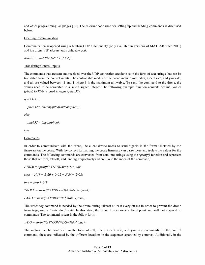
and other programming languages [10]. The relevant code used for setting up and sending commands is discussed
below.
Opening Communication
Communication is opened using a built-in UDP functionality (only available in versions of MATLAB since 2011)
and the drone’s IP address and applicable port:
drone1 = udp('192.168.1.1', 5556);
Translating Control Inputs
The commands that are sent and received over the UDP connection are done so in the form of text strings that can be
translated from the control inputs. The controllable modes of the drone include roll, pitch, ascent rate, and yaw rate,
and all are valued between -1 and 1 where 1 is the maximum allowable. To send the command to the drone, the
values need to be converted to a 32-bit signed integer. The following example function converts decimal values
(pitch) to 32-bit signed integers (pitch32):
if pitch < 0
pitch32 = bitcon(-pitch)-bitcon(pitch);
else
pitch32 = bitcon(pitch);
end
Commands
In order to communicate with the drone, the client device needs to send signals in the format dictated by the
firmware on the drone. With the correct formatting, the drone firmware can parse these and isolate the values for the
commands. The following commands are converted from data into strings using the sprintf() function and represent
those that set trim, takeoff, and landing, respectively (where ind in the index of the command):
FTRIM = sprintf('AT*FTRIM=%d\r',ind);
zero = 2^18 + 2^20 + 2^22 + 2^24 + 2^28;
one = zero + 2^9;
TKOFF = sprintf('AT*REF=%d,%d\r',ind,one);
LAND = sprintf('AT*REF=%d,%d\r',1,zero);
The watchdog command is needed by the drone during takeoff at least every 30 ms in order to prevent the drone
from triggering a “watchdog” state. In this state, the drone hovers over a fixed point and will not respond to
commands. The command is sent in the follow form:
WDG = sprintf('AT*COMWDG=%d\r',ind1);
The motors can be controlled in the form of roll, pitch, ascent rate, and yaw rate commands. In the control
command, these are indicated by the different locations in the sequence separated by commas. Additionally in the

Page 7 of 13
American Institute of Aeronautics and Astronautics
control command is a mode indicator in sequence after the index of the command (ind); where a mode of 1 allows
for commands for roll and pitch to be sent and 0 only allows yaw rate:
CTRL = sprintf('AT*PCMD=%d,%d,%d,%d,%d,%d\r',ind,1,roll,pitch,asrate,yawrate);
Once the commands are converted to strings, the commands are sent to the drone using the fprintf() function. An
example is shown below using the watchdog command:
fprintf(drone1, WDG);
B. Testing Setup
A total of four scenarios were setup for the heuristic to be validated on. Three of the tests were static scenarios with
varying number of requests, and the last scenario included several static requests and one dynamically arriving
request. All request and initial UAV locations were chosen randomly within the limits of the useable flying area.
The depot was user-defined as a semi-central location and varied for each scenario. Furthermore, 3 cases were run
for each of the static tests to allow for better analysis of methods. Each of the tests performed are described in more
detail below.
Test #1
Test #1 was a static scenario where all requests are known at the beginning of the mission. This test included a
single UAV and a total of 5 requests that each needed to be visited once before the UAV returned to the depot. Both
a minimum distance and a minimum delivery latency approach were used to solve and flight test the scenario.
Test #2
Test #2 was also a static scenario where all requests are known at the beginning of the mission. This test included a
single UAV and a total of 8 requests and is otherwise, similar to Test #1.
Test #3
Test #3 was also a static scenario where all requests are known at the beginning of the mission. This test included a
single UAV and a total of 12 requests and is otherwise, similar to Test #1 and #2.
Test #4
Test #4 was a dynamic scenario where some requests are known at the beginning of the mission and some are only
known of as the mission evolves. This test included a single UAV and a total of 7 static requests and 1 dynamic
request; which results in a Degree of Dynamism (DoD) of 1/8. Only a minimum delivery latency method was used
in this scenario. Because the minimum distance solution was obtained using an optimal, brute force strategy, it was
not possible to recalculate a solution in a reasonable time as new targets arrive. Therefore, test #4 was only
completed to validate the use of the heuristic in dynamic scenarios.
In addition to single vehicle tests, it was attempted to fly multiple quadrotors in the laboratory setting. Due to the
small area and downdraft from the drones, the precision needed combined with the oscillations made it impossible to
fly any realistic missions. The instability caused the drones to leave the small area where camera feedback is
possible and behave erratically. Future testing should be done in either a larger area or outdoors with multiple
drones.

Page 8 of 13
American Institute of Aeronautics and Astronautics
C. Waypoint Following Algorithm
In the validation of algorithms for task allocation and routing, a sub-problem presents itself. When using quadrotors
like the AR Drone, inputs into the drone are in the form of motor control. Therefore once the task allocation
algorithms output an order of which to visit waypoints, the drone controls need to be manipulated to travel to the
waypoints. An overview of the control challenge of waypoint following is shown below in Figure 6. The drone uses
the error in position between itself and the current waypoint and the velocity as inputs into the controller and outputs
roll, pitch, and yaw rate. These control outputs are then fed to the drone to use to navigate towards a zero error in
position. Several different control methods were explored for use as a waypoint following algorithm. Both
traditional and intelligent methods were applied: PID and Fuzzy Logic Control (FLC).
Figure 6: Waypoint Following Control Problem
Because the focus of this aspect of the research was on validation of heuristic algorithms, a FLC method was chosen
for use. While a PID controller might give slightly better paths (less divergence from straight-line paths) and allow
for a mildly better comparison of methods, using intelligent control methods helps to highlight the feasibility of
using them for future applications. Also, a complete comparison of methods would require a Monte Carlo analysis.
However since the area was so small and camera view is limited, this wouldn’t be worth completing in this lab
environment anyway. Future work should be done to move the testing to either a bigger space or outdoors and allow
for multiple vehicles.
By keeping the yaw at 0, the control problem can be simplified significantly. That is, the pitch and roll can be
essentially controlled independently to correspond to movement in the y- and x- direction, respectively. Therefore, a
PD controller was implemented to keep the yaw at 0 and a FLC was used for lateral motion. For the PD controller,
the proportional and derivative gains were 1 and 0.16, respectively. Two almost identical Fuzzy Inference Systems
(FISs) were developed to control the roll and pitch based on the position and velocity error (Figure 7).
Figure 7: Waypoint Following FLC Overview
The rules for the waypoint following FISs for roll and pitch are essentially identical and follow the same principles
as PID controllers: apply the maximum negative output when both the positional error is large and the velocity is
pushing the error larger and vice versa. Furthermore if the velocity is already pushing the error towards zero, a lesser
magnitude output can be applied.

Page 9 of 13
American Institute of Aeronautics and Astronautics
Figure 8: Waypoint Following FLC Decision Surface
III. Results
This section summarizes the results of the laboratory testing. Both validation of the heuristic and a brief analysis are
presented. Because of the limited space, testing was only completed using a single drone. Furthermore, only a
limited number of cases were compared for each testing scenario due to limited battery life.
A. Validation
The following figures (Figure 9, Figure 10, and Figure 11) show the validation of the heuristic algorithm based on a
minimum delivery latency objective function and an optimal minimum distance solution to each of the static tests,
respectively. The blue paths represent the straight-line paths whereas the green represents the actual path taken by
the drone in each case.
Figure 9: Flight Test 1 Sample Solutions
1
2
3
4
5
1
Test 1 - Min Latency
1
2
3
4
5
1
Test 1 - Min Distance

Page 10 of 13
American Institute of Aeronautics and Astronautics
Figure 10: Flight Test 2 Sample Solutions
Figure 11: Flight Test 3 Sample Solutions
In addition to validation on static cases, the algorithms were tested on a dynamic case since most scenarios involving
UAVs are dynamic in nature. Again, this test included 7 static requests and 1 dynamic request which only came to
be known after the initial mission planning was already done. It can be seen in the figure below (Figure 12) the
validation of the flight test with both the initial and recalculated paths. In this figure, the lighter, thinner, blue line
represents the initial path, and once the new request appears, it recalculates the revised, thicker, red dotted-lined
path. It can be seen that for the most part, the path is very similar, and the new target is incorporated into another
cluster since the UAV has yet to reach those requests when the new target appears. If the UAV had already visited
that cluster, the new target would be in its own new cluster and most likely visited after the other, larger clusters.
1
2
3
4 56
7
8
1
Test 2 - Min Latency
1
234
5
67
8
1
Test 2 - Min Distance
12
3
4
5
6
7
8
9
10
11
12
1
Test 3 - Min Latency
12
3
4
5
6
7
8
9
10
11
12
1
Test 3 - Min Distance

Page 11 of 13
American Institute of Aeronautics and Astronautics
Figure 12: Flight Test 4 – Dynamic Scenario Solution
This validation of the heuristic in dynamic scenarios in MATLAB emphasizes its usability as this research evolves
from laboratory testing to outdoors. Since MATLAB is not a compiled language, it tends to run much slower than
typical programs used in real flight tests. Furthermore since MATLAB does not allow threading, the solution needed
to be recalculated in the same time step as other processing (i.e. gathering camera feedback, calculating commands,
etc). This represented a challenge, because the AR Drone needs commands every 30 ms or it goes into a watchdog
state. The fact that a solution could be recalculated in real-time using a relatively slow language before the drone
went into a safety state proves that this is practical to use in real missions.
B. Analysis
Again, there were 3 cases run for each of test 1, 2, and 3, and the averages of the latency of request delivery were
taken over all 3 cases for each method. For test 4, only validation was completed, and therefore, analysis is left out
here. This was due to the fact that re-computing the minimum distance solution in real-time is not feasible, and
therefore, there is nothing to compare results to. The average target delivery time over all cases for the each test are
shown below in Table 1.
Table 1: Experimental Results: Average Delivery Time of Targets (in Seconds)
Min
Latency
Min
Distance
Min Dist
Min Lat
Test 1
Static Scenario
1 UAV, 5 Targets
29.4 32.8 1.117
Test 2
Static Scenario
1 UAV, 8 Targets
23.0 41.3 1.797
Test 3
Static Scenario
1 UAV, 12 Targets
35.1 49.7 1.416

Page 12 of 13
American Institute of Aeronautics and Astronautics
Additionally, the minimum distance solution’s average delivery cost was compared to the minimum delivery latency
(last column) to gain a better idea of how much time can be saved using this new cost function in more realistic
scenarios. The results above show that time can be saved when utilizing a minimum delivery latency objective
function, but obviously, how much time depends on the specific case. This is indicated by the values in the last
column all being greater than 1. For example in Test #1, this can be read as: the average time waited per target to be
delivered for the minimum distance solution was 1.117 times longer than the minimum delivery latency solution. For
Test #2, it is 1.797 times longer and for Test #3, 1.416 times longer. This further shows the need for effective
routing under limited communication conditions since often a minimum distance cost function is adopted.
IV. Conclusions
UAVs are being increasingly used for missions that are considered “dull, dirty, and dangerous.” Furthermore,
communications represented a realistic constraint in everyday operation. In related investigations, it was found that a
previously unexplored area was the lack of problem formulations to route UAVs when communication is highly
restricted. A variation of the VRP was developed where data needed to be “picked up” from requests and
“delivered” to a high bandwidth connection. In this formulation, information is not considered delivered until it is
returned to the depot, and a minimum delivery latency objective function is adopted. Because this problem
formulation was previously unexplored, many different solution strategies were applied and evaluated. It is well
known that optimal solutions for realistic scenarios of VRPs can be computationally complex, and trying to maintain
the objective of minimizing the latency in a dynamic environment makes this even more difficult. Because most
scenarios involving UAVs are dynamic in nature, formulations that can extend to these environments are of interest.
Here, we have preserved this objective by using a heuristic solution that approximates the behavior of the optimal
solution and scales in polynomial time. Additionally for more practical scenarios where there is uncertainty, a robust
algorithm is required, which can be obtained by a good heuristic solution.
In this research, the algorithms developed were validated on real systems. Commercially available AR Drones and
an Optitrack 12-camera system for feedback were used in a laboratory setting to recreate relevant task allocation
scenarios. Static scenarios were solved using an optimal minimum distance strategy and the heuristic developed here
for a minimum delivery latency solution. Results validate that time can be saved using the new problem formulation
when communication is highly restricted. Furthermore, the heuristic was confirmed to work in real-time to solve
situations with dynamic requests highlighting its ability to be used in practical situations.
Acknowledgments
C. Sabo acknowledges that this work was funded by the Dayton Area Graduate Studies Institute (DAGSI).

Page 13 of 13
American Institute of Aeronautics and Astronautics
References
1. R. A. Best, “Intelligence, Surveillance, and Reconnaissance (ISR) Programs: Issues for Congress,” CRS Report
for Congress, CRS Web, RL32508, February 22, 2005, Library of Congress.
2. Shima, T., and Rasmussen, S., Editors, “UAV Cooperative Decision and Control – Challenges and Practical
Approaches,” Advances in Design and Control, SIAM, 2009.
3. Fahlstrom, P.G., and Gleason, T.J., “Introduction to UAV Systems,” 3rd Edition, UAV Systems Inc., 2009.
4. Laporte, “The Vehicle Routing Problem: An Overview of Exact and Approximate Algorithms,” 1991.
5. Sabo, C., Kingston, D., and Cohen, K., “Minimum Service Time for UAV Cooperative Control Subject to
Communication Constraints,” Air Force Research Laboratory, 2010 AIAA Infotech@Aerospace, Atlanta,
Georgia, 20-22 April 2010, AIAA-2010-3344.
6. Sabo, C. and Cohen, K., “SMART Heuristic for Pickup and Delivery Problem with Cooperative UAVs,” Air
Force Research Laboratory, AIAA Infotech@Aerospace, St. Louis, Missouri, 29-31 March 2011, AIAA-2011-
1464.
7. Sabo, C. and Cohen, K., “Dynamic Allocation of Unmanned Aerial Vehicles with Communication Constraints,”
2012 AIAA Infotech@Aerospace, Garden Grove, California, 19-21 June 2012, AIAA-2012-2455.
8. Parrot AR Drone 2.0, 2012. http://ardrone2.parrot.com/
9. Natural Point OptiTrack Tracking System, 2012. http://www.naturalpoint.com/optitrack
10. DIY Drones, 2012. http://diydrones.com/
11. MathWorks – MATLAB and Simulink for Technical Computing, The MathWorks Inc, 2012.
http://www.mathworks.com/