Reliability Analysis of Serviceability Limit State for Braced ...

Experimental Study of Local Buckling, Overstrength,and Fracture of Links in Eccentrically Braced Frames
Taichiro Okazaki1; Gabriela Arce2; Han-Choul Ryu3; and Michael D. Engelhardt, M.ASCE4
Abstract: A total of 23 tests were conducted to study the cyclic loading performance of links in steel eccentrically braced frames. Theobjectives of these tests were to reevaluate flange slenderness limits and overstrength factors for links. The effect of loading history onlink performance was also investigated. Link specimens were constructed from five different wide-flange sections, all of ASTM A992 steel,with various lengths ranging from short shear yielding links to very long flexural yielding links. In addition to providing data on theeffects of flange buckling and overstrength, these tests also showed some unexpected failure modes. The paper provides an overview ofthis experimental investigation, describing the overall research program, as well as details of the test specimens and test results. The paperconcludes with a number of design recommendations for links in eccentrically braced frames.
DOI: 10.1061/�ASCE�0733-9445�2005�131:10�1526�
CE Database subject headings: Cyclic tests; Steel structures; Seismic design; Flanges; Slenderness ratio; Loading history; Fractures;Buckling.
Introduction
The design intent for a steel eccentrically braced frame �EBF� isthat inelastic action under strong earthquake motion is restrictedprimarily to the links, which are designed and detailed to providelarge levels of cyclic ductility. The rather extensive experimentaldatabase on EBF link behavior, which has led to current buildingcode rules, has been conducted almost exclusively on wide-flangeshapes of ASTM A36 steel �Popov and Engelhardt 1988�. How-ever, in current practice, wide-flange sections are typically madeof the higher strength ASTM A992 steel. With the higher yieldstrength of 345 MPa for A992 steel, a number of rolled wide-flange shapes now violate flange slenderness limits in the 2002AISC Seismic Provisions for Structural Steel Buildings �AISC2002�, hereinafter referred to as the 2002 AISC Seismic Provi-sions. Many of these same sections previously satisfied flangeslenderness limits when made of A36 steel. The shift to A992steel has therefore eliminated a number of rolled wide-flangeshapes from use in EBFs. This, in turn, has led to questions on theappropriateness of current flange slenderness limits for linkbeams. The effect of flange slenderness on link behavior has notbeen explicitly addressed in past research.
1Research Assistant, Dept. of Civil Engineering, The Univ. of Texas atAustin, Austin, TX 78712-0275 �corresponding author�. E-mail:[email protected]
2Associate, Estruconsult, San José, Costa Rica.3Engineer, Englekirk & Sabol Consulting Structural Engineers, Inc.,
Los Angeles, CA 90018.4Professor, Dept. of Civil Engineering, The Univ. of Texas at Austin,
Austin, TX 78712-0275.Note. Associate Editor: Donald W. White. Discussion open until
March 1, 2006. Separate discussions must be submitted for individualpapers. To extend the closing date by one month, a written request mustbe filed with the ASCE Managing Editor. The manuscript for this paperwas submitted for review and possible publication on February 10, 2004;approved on October 28, 2004. This paper is part of the Journal ofStructural Engineering, Vol. 131, No. 10, October 1, 2005. ©ASCE,
ISSN 0733-9445/2005/10-1526–1535/$25.00.1526 / JOURNAL OF STRUCTURAL ENGINEERING © ASCE / OCTOBER 2
An additional issue of recent concern is the degree of over-strength that can be developed by a link. Link overstrength isdefined as the maximum shear force developed by the link di-vided by the plastic shear strength of the link. Link overstrengthis primarily due to strain hardening, but can also be due to thedevelopment of shear resistance in the link flanges. The link over-strength factor is used to estimate the maximum forces that can begenerated by a fully yielded and strain hardened link, which inturn, is then used to design the diagonal brace, the beam segmentoutside of the link, and the columns of the EBF. Past researchershave generally recommended a link overstrength factor of 1.5�Popov and Engelhardt 1988�. Currently, the 2002 AISC SeismicProvisions specify a link overstrength factor of 1.25 for design ofthe diagonal brace, and an overstrength factor of 1.1 for the de-sign of the beam segment outside of the link and for the columns.As described in the Commentary of the 2002 AISC Seismic Pro-visions, capacity design rules in the Provisions are based on anassumed overstrength factor of 1.5. The actual specified factorsare less than 1.5 for a number of reasons, including the use of theRy factor to account for material overstrength, the use of resis-tance factors when computing the strength of the brace and othermembers outside of the link, the ability to sustain limited yieldingin members outside of the link, and other factors. However, recenttests on large built-up shear links for use in bridge applicationsshowed overstrength factors of nearly 2 �Itani et al. 1998;McDaniel et al. 2003�. This has led to concerns that current over-strength factors may be unconservative, particularly for shapeswith heavy flanges, where shear resistance of the flanges contrib-utes significantly to overstrength.
An experimental investigation was conducted to examineflange buckling and overstrength in links constructed of A992steel. One objective of this investigation was to determine if thecurrent flange slenderness limit can be relaxed to permit a largernumber of rolled wide-flange shapes to be used in EBFs. Morespecifically, the objective was to determine if the flange slender-ness limit, bf /2tf, can be increased from the current limit of0.30�E /Fy�1/2 to 0.38�E /Fy�1/2. The less stringent limit corre-
sponds to that specified for plastic design in the AISC Load and005
Resistance Factor Design Specification for Structural Steel Build-ings �AISC 1999�. The second objective was to reexamine linkoverstrength factors, particularly for rolled wide-flange shapeswith a large ratio of flange to web area. A third objective of thisexperimental program, as described later, was to also evaluate theeffect of loading sequence on link performance. This experimen-tal study was part of a larger investigation that included extensiveanalytical and finite element studies of EBF and link behavior.This paper only describes the experimental investigation. Infor-mation on the analytical and finite element studies is available inRichards and Uang �2002, 2003�.
Experimental Program
Test Setup and Test Specimens
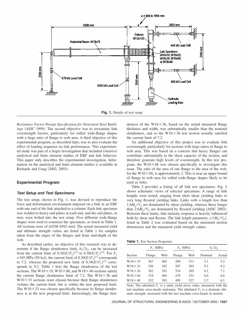
The test setup, shown in Fig. 1, was devised to reproduce theforce and deformation environment imposed on a link in an EBFwith one end of the link attached to a column. Each link specimenwas welded to heavy end plates at each end, and the end plates, inturn, were bolted into the test setup. Five different wide-flangeshapes were used to construct the specimens, as listed in Table 1.All sections were of ASTM A992 steel. The actual measured yieldand ultimate strength values are listed in Table 1 for samplestaken from the edges of the flanges and from mid-depth of theweb.
As described earlier, an objective of this research was to de-termine if the flange slenderness limit, bf /2tf, can be increasedfrom the current limit of 0.30�E /Fy�1/2 to 0.38�E /Fy�1/2. For Fy
=345 MPa �50 ksi�, the current limit of 0.30�E /Fy�12 correspondsto 7.2, whereas the proposed new limit of 0.38�E /Fy�1/2 corre-sponds to 9.2. Table 1 lists the flange slenderness of the testsections. The W10�19, W10�68, and W18�40 sections satisfythe current flange slenderness limit of 7.2. The W16�36 andW10�33 sections were chosen because their flange slendernessviolates the current limit, but is within the new proposed limit.The W10�33 was chosen specifically because its flange slender-
Fig. 1. De
ness is at the new proposed limit. Interestingly, the flange slen-
JOURNAL
derness of the W16�36, based on the actual measured flangethickness and width, was substantially smaller than the nominalslenderness, and so the W16�36 test section actually satisfiedthe current limit of 7.2.
An additional objective of this project was to evaluate linkoverstrength, particularly for sections with large ratios of flange toweb area. This was based on a concern that heavy flanges cancontribute substantially to the shear capacity of the section, andtherefore generate high levels of overstrength. In this test pro-gram, the W10�68 was chosen specifically to investigate thisissue. The ratio of the area of one flange to the area of the web,for the W10�68, is approximately 2. This is near an upper boundof flange to web area for rolled wide-flange shapes likely to beused as links.
Table 2 provides a listing of all link test specimens. Fig. 2shows schematic views of selected specimens. A range of linklengths were tested, ranging from short shear yielding links tovery long flexural yielding links. Links with a length less than1.6Mp /Vp are dominated by shear yielding, whereas those longerthan 2.6Mp /Vp are dominated by flexural yielding �AISC 2002�.Between these limits, link inelastic response is heavily influencedboth by shear and flexure. The link length parameter, e / �Mp /Vp�,listed in Table 2 was evaluated based on the measured sectiondimensions and the measured yield strength values.
Table 1. Test Section Properties
Section
Fy �MPa� Fu �MPa� bf /2tf
Flange Web Flange Web Nominal Actual
W10�19 367 405 509 531 5.1 5.2
W10�33 356 382 507 503 9.1 9.2
W16�36 362 392 534 565 8.1 7.1
W10�68 319 404 479 531 6.6 6.6
W18�40 352 393 499 527 5.7 6.1
Note: The tabulated Fy is a static yield stress value, measured with thetest machine cross-heads stationary. The tabulated Fu is a dynamic ulti-
test setup
tails ofmate strength, measured with the test machine cross-heads in motion.
OF STRUCTURAL ENGINEERING © ASCE / OCTOBER 2005 / 1527
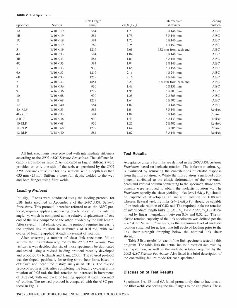
All link specimens were provided with intermediate stiffenersaccording to the 2002 AISC Seismic Provisions. The stiffener lo-cations are listed in Table 2. As indicated in Fig. 2, stiffeners wereprovided on only one side of the web, as permitted by the 2002AISC Seismic Provisions for link sections with a depth less than635 mm �25 in.�. Stiffeners were full depth, welded to the weband both flanges using fillet welds.
Loading Protocol
Initially, 17 tests were conducted using the loading protocol forEBF links specified in Appendix S of the 2002 AISC SeismicProvisions. This protocol, hereafter referred to as the AISC pro-tocol, requires applying increasing levels of cyclic link rotationangle, �, which is computed as the relative displacement of oneend of the link compared to the other, divided by the link length.After several initial elastic cycles, the protocol requires increasingthe applied link rotation in increments of 0.01 rad, with twocycles of loading applied at each increment of rotation.
After observing a number of shear link specimens fail toachieve the link rotation required by the 2002 AISC Seismic Pro-visions, it was decided that six of those specimens be duplicatedand tested using a revised loading protocol recently developedand proposed by Richards and Uang �2003�. The revised protocolwas developed specifically for testing short shear links, based onextensive nonlinear time history analysis of EBFs. The revisedprotocol requires that, after completing the loading cycle at a linkrotation of 0.05 rad, the link rotation be increased in incrementsof 0.02 rad, with one cycle of loading applied at each incrementof rotation. The revised protocol is compared with the AISC pro-
Table 2. Test Specimens
Specimen SectionLink Length
�mm�
1A W10�19 584
1B W10�19 584
1C W10�19 584
2 W10�19 762
3 W10�19 1219
4A W10�33 584
4B W10�33 584
4C W10�33 584
5 W10�33 930
6A W10�33 1219
6B W10�33 1219
7 W10�33 1854
8 W16�36 930
9 W16�36 1219
10 W10�68 930
11 W10�68 1219
12 W18�40 584
4A-RLP W10�33 584
4C-RLP W10�33 584
8-RLP W16�36 930
10-RLP W10�68 930
11-RLP W10�68 1219
12-RLP W18�40 584
tocol in Fig. 3.
1528 / JOURNAL OF STRUCTURAL ENGINEERING © ASCE / OCTOBER 2
Test Results
Acceptance criteria for links are defined in the 2002 AISC SeismicProvisions based on inelastic rotation. The inelastic rotation, �p,is evaluated by removing the contributions of elastic responsefrom the link rotation, �. While the link rotation � included com-ponents attributed to the elastic deformation of the horizontalbeam and vertical column connecting to the specimen, those com-ponents were removed to obtain the inelastic rotation �p. TheProvisions specify the shear yielding links �e�1.6Mp /Vp� shouldbe capable of developing an inelastic rotation of 0.08 rad,whereas flexural yielding links �e�2.6Mp /Vp� should be capableof an inelastic rotation of 0.02 rad. The required inelastic rotationof intermediate length links �1.6Mp /Vp�e�2.6Mp /Vp� is deter-mined by linear interpolation between 0.08 and 0.02 rad. The in-elastic rotation capacity of the link specimens was defined per the2002 AISC Seismic Provisions, as the maximum level of inelasticrotation sustained for at least one full cycle of loading prior to thelink shear strength dropping below the nominal link shearstrength.
Table 3 lists results for each of the link specimens tested in thisprogram. The table lists the actual inelastic rotation achieved byeach specimen, as well as the inelastic rotation required by the2002 AISC Seismic Provisions. Also listed is a brief description ofthe controlling failure mode for each specimen.
Discussion of Test Results
Specimens 1A, 1B, and 6A failed prematurely due to fractures at
/ �Mp /Vp�Intermediate
stiffenersLoadingprotocol
1.73 3@146 mm AISC
1.73 3@146 mm AISC
1.73 3@146 mm AISC
2.25 4@152 mm AISC
3.61 152 mm from each end AISC
1.04 3@146 mm AISC
1.04 3@146 mm AISC
1.04 3@146 mm AISC
1.65 5@156 mm AISC
2.16 4@244 mm AISC
2.16 4@244 mm AISC
3.29 305 mm from each end AISC
1.49 6@133 mm AISC
1.95 5@203 mm AISC
1.25 2@305 mm AISC
1.64 3@305 mm AISC
1.02 3@146 mm AISC
1.04 3@146 mm Revised
1.04 3@146 mm Revised
1.49 6@133 mm Revised
1.25 2@305 mm Revised
1.64 3@305 mm Revised
1.02 3@146 mm Revised
e
the fillet welds connecting the link flanges to the end plates. These
005

failures are considered an artifact of the test setup, as the link endconnections used for the specimens were not representative oftypical link end connection details used in actual EBFs. Thus,while the failure of the end connections in these three specimensis of some interest, these three specimens will be excluded fromthe remaining discussion. Excluding Specimens 1A, 1B, and 6A,there are 20 remaining specimens that were not affected by fail-ures at the link end connections, and can therefore be consideredas providing valid fundamental data on the behavior of links. Inthe following sections, key aspects of the test results are dis-cussed.
Link Web Fracture
A notable feature observed in these tests, which was not typicallyreported in earlier tests, was fracture of the link web. All speci-mens with a length of e�1.7Mp /Vp exhibited link web fracturesinitiating at the top and bottom end of the stiffeners, at the pointof termination of the fillet welds connecting the stiffeners to thelink web. These fractures often propagated in a horizontal direc-tion, running parallel to the flanges, and ultimately grew large
Fig. 2. Details of selected link specimens: �a� Specimen
enough to cause complete failure of the link.
JOURNAL
Specimen 4A provides an example of such a failure. Fig. 4shows the hysteretic response of this specimen and Fig. 5 showsthe specimen after testing. Fractures running across the top andbottom of the web are visible in this photo. These fractures lim-ited the inelastic rotation capacity of the specimen to 0.061 rad,falling short of the 0.08 rad required by the 2002 AISC SeismicProvisions. Many of the shear link specimens tested using theAISC loading protocol failed to achieve their required inelasticlink rotations due to this type of fracture.
Based on a review of past link tests, it appears that fracture ofthe link web as described above has not been previously reported.While fractures of link webs were reported in earlier tests, forexample by Hjelmstad and Popov �1983�, and Malley and Popov�1983�, those fractures generally occurred after the developmentof severe web buckling. Fractures in past tests developed in linkweb panels at locations of large localized deformation due to localweb or flange buckling, after inelastic instability caused signifi-cant degradation in link forces. Such fractures were also observedin this test program, for example in Specimens 1C and 6B, whichachieved their required inelastic rotations under the AISC loadingprotocol.
A-RLP� and 4C �4C-RLP�; and �b� Specimen 8 �8-RLP�
4A �4Unlike the fractures reported in the literature, a number of
OF STRUCTURAL ENGINEERING © ASCE / OCTOBER 2005 / 1529

specimens in this program developed web fractures at the ends ofstiffener welds prior to the occurrence of any web buckling, oronly after very mild buckling, as exhibited by Specimen 4A. Thistype of failure appears to be quite different from that observed inpast tests. An exception is a recent test on a very large built-uplink section tested for use in the new east span of the SanFrancisco–Oakland Bay Bridge �McDaniel et al. 2003�. In thistest, a fracture initiated at the termination of a stiffener weld priorto web buckling, although the fracture propagated diagonallyacross the web, compared to the horizontal fracture propagationobserved in Specimen 4A. Analysis of the failure �McDaniel et al.2003� suggested that the cause was a stress concentration at theend of the stiffener weld, because the stiffener was terminated tooclose to the flange-to-web groove weld of the built-up section.Based on finite element analysis, McDaniel et al. �2003� recom-mended terminating the stiffener weld further from the flange-to-web weld, and suggested a minimum distance of three times theweb thickness.
The first specimen in this program to exhibit a horizontal webfracture initiating at the end of a stiffener weld was Specimen 4A.After this failure, and based on the recommendations ofMcDaniel et al. �2003�, the stiffeners were terminated at a largerdistance from the flange in the subsequent Specimens 4B and 4C.In going from Specimens 4A to 4B, and then to 4C, the termina-tion of the stiffener weld was moved progressively further fromthe flange. In Specimen 4C, the stiffener welds were terminated adistance of approximately five times the web thickness from the“k-line” of the section �see Fig. 2�a��. The k-line is the locationwhere the web meets the flange-web fillet. The test results �seeTable 3� show that larger inelastic rotations were achieved, as thestiffener welds were moved further from the k-line. However,even for Specimen 4C, which had the stiffener welds terminated
Fig. 3. Loading protocols: �a� AISC protocol; and �b� revised loadingprotocol proposed by Richards and Uang �2003�
quite a large distance from the k-line, the horizontal fractures still
1530 / JOURNAL OF STRUCTURAL ENGINEERING © ASCE / OCTOBER 2
ultimately developed. Thus, while moving the stiffener welds fur-ther from the k-line was beneficial, it did not eliminate the prob-lem entirely. For all specimens tested after Specimens 4A–4C, thestiffener welds were terminated a distance of five times the webthickness from the k-line, but many still exhibited fractures initi-ating at the stiffener ends.
The proximity of the fractures in many of the test specimens tothe k-line of the section suggests that material properties in thek-area may have played a role in these fractures. The 2002 AISCSeismic Provisions indicate that the steel in the k-area of rolledwide-flange shapes �the region where the web meets the flange�can exhibit high hardness and be prone to fracture. Consequently,for the sections used in this test program, material properties weremeasured within this area. These measurements did in fact showhighly elevated hardness levels and significantly reduced levels oftensile coupon elongation in the k-areas of the test sections, withthe exception of the W10�19. Nonetheless, the role of the k-areamaterial properties in the observed fractures is unclear, and isunder continued investigation by the writers.
After link web fracture was observed in a number of these testspecimens, Richards and Uang �2002� noted that the typical load-ing sequences used in shear link tests conducted in the 1970s and
Table 3. Test Results
Specimen
�p �rad�
Observed failure modeRequired Test
1A 0.072 0.042 Fracture at link end plate connection
1B 0.072 0.060 Fracture at link end plate connection
1C 0.072 0.081 Flange and web buckling followedby fracture in web
2 0.041 0.070 Flange and web buckling followedby fracture in flange near link end
3 0.020 0.041 Flange and web buckling followedby fracture in flange near link end
4A 0.080 0.061 Fracture of web at stiffener weld
4B 0.080 0.071 Fracture of web at stiffener weld
4C 0.080 0.080 Fracture of web at stiffener weld
5 0.077 0.067 Fracture of web at stiffener weld
6A 0.046 0.047 Fracture at link end plate connection
6B 0.046 0.059 Flange and web buckling followedby fracture in web
7 0.020 0.037 Flange, web and lat. tor. buckling
8 0.080 0.077 Flange and web buckling followed byfracture in web at stiffener weld
9 0.059 0.048 Flange and web buckling
10 0.080 0.073 Fracture of web at stiffener weld
11 0.078 0.068 Fracture of web at stiffener weld
12 0.080 0.091 Fracture of web at stiffener weldaccompanied by web buckling
4A-RLP 0.080 0.120 Fracture of web at stiffener weld
4C-RLP 0.080 0.119 Fracture of web at stiffener weld
8-RLP 0.080 0.117 Flange and web buckling followedby fracture in web at stiffener weld
10-RLP 0.080 0.113 Fracture of web at stiffener weld
11-RLP 0.078 0.087 Fracture of web at stiffener weld;link rotation limited by ram stroke
12-RLP 0.080 0.119 Fracture of web at stiffener weldaccompanied by web buckling
1980s were less severe compared to the AISC protocol used for
005

the tests in this current program. Further, there appeared to be norational basis for the link loading protocol specified in AppendixS of the 2002 AISC Seismic Provisions. As a result, Richards andUang �2003� developed a revised loading protocol for testingshort shear links, which was used for the first time in this re-search. This revised loading protocol for shear links was devel-oped using a methodology similar to that used for moment frameconnection testing, as developed under the FEMA/SAC program�Krawinkler et al. 2000�.
Six shear link specimens that experienced link web fracture inthe initial series of tests in this program were duplicated andtested using the revised loading protocol �RLP�. All six speci-mens, namely, 4A-RLP, 4C-RLP, 8-RLP, 10-RLP, 11-RLP, and12-RLP achieved link rotations well in excess of the requiredlevel. In fact, as indicated by the data in Table 3, these specimensdeveloped inelastic rotations on the order of 10 to 50% greaterthan those required in the 2002 AISC Seismic Provisions. Itshould be noted that the inelastic rotation developed by Specimen11-RLP was limited due to limitations in the stroke of the loadingram. Nonetheless, even this specimen developed an inelastic ro-tation that exceeded the required value.
The results of the initial link tests using the AISC loadingprotocol indicated that link web fracture can be delayed by in-creasing the distance from the k-line to the termination of thestiffener to link web fillet weld. The stiffener welding details hada less significant effect on the results of the tests using the revised
Fig. 4. Response of specimen 4A
Fig. 5. Specimen 4A after testing
JOURNAL
loading protocol. Specimens 4A-RLP and 4C-RLP were bothtested using the revised loading protocol. These specimens wereidentical except for the stiffener welding details. In Specimen4A-RLP, the stiffener welds were terminated close to the k-line.In Specimen 4C-RLP, the termination of the stiffener weld wasmoved farther from the k-line. As indicated in Table 3, Specimen4C-RLP and Specimen 4A-RLP achieved the same inelastic rota-tion of �p= ±0.12 rad. Even with the stiffener weld terminatednear the k-line, Specimen 4A-RLP developed an inelastic rotationgreater than the ±0.08 rad required by the 2002 AISC SeismicProvisions. Thus, providing a generous distance between thek-line and the stiffener weld termination, while perhaps not es-sential for satisfactory link performance, can result in higher linkrotation capacity. In order to delay the onset of link web fracture,the stiffener welds were terminated a distance of 5*tw from thek-line of the link section in the majority of the test specimens,where tw is the link web thickness. Although chosen somewhatarbitrarily, this appears to provide a reasonable basis for design.
Loading Protocol
This test program permitted a direct comparison of the perfor-mance of nominally identical link specimens tested using twodifferent loading protocols: the AISC loading protocol �per Ap-pendix S of the 2002 AISC Seismic Provisions� versus the revised
Fig. 6. Response of specimen 4A-RLP
Fig. 7. Specimen 4A-RLP after testing
OF STRUCTURAL ENGINEERING © ASCE / OCTOBER 2005 / 1531
loading protocol �per Richards and Uang 2003�. To illustrate theeffect of loading protocol, Fig. 4 shows the hysteretic response ofSpecimen 4A, which was tested using the AISC loading protocol.In comparison, Fig. 6 shows the hysteretic response of Specimen4A-RLP, which was nominally identical to Specimen 4A, exceptthat 4A-RLP was tested using the revised loading protocol. Speci-men 4A-RLP developed an inelastic rotation capacity of0.120 rad, as compared to 0.061 rad for Specimen 4A.
As illustrated by Specimens 4A and 4A-RLP, the loading pro-tocol used to test the link specimens has a very large effect on theinelastic rotation capacity achieved by the link. Links tested withthe revised loading protocol achieved inelastic rotations that werefrom 28 to 97% greater than links tested with the AISC loadingprotocol. The average increase in inelastic rotation using the re-vised loading protocol was 52%. Since the loading protocol hassuch a large effect on link test results, it is important that loadingprotocols be selected that realistically reflect link demands underactual earthquake loading, as represented by the work by Rich-ards and Uang �2003�. The revised loading protocol by Richardsand Uang currently only applies to short shear yielding links witha length of e�1.6Mp /Vp. This work should be extended to alsodevelop a rational loading protocol for longer links.
Whereas the loading protocol had a large effect on link inelas-tic rotation capacity, the loading protocol did not significantlychange the controlling failure mode for the link. Links testedusing the AISC loading protocol exhibited essentially the samefailure mode as the nominally identical links tested using therevised loading protocol. Links that failed due to fracture of thelink web under the AISC loading protocol still failed by fractureof the link web under the revised loading protocol. Fig. 7 is aphoto of Specimen 4A-RLP after testing, showing the link webfractures that ultimately caused failure of this specimen. This fail-ure mode is very similar to that observed in Specimen 4A �Fig. 5�.However, under the revised loading protocol, significantly higherinelastic rotations were achieved prior to link web fracture.
Regardless of loading protocol, many of the shear links testedin this research program failed by fracture of the link web, withthe fractures initiating at the termination of stiffener welds. Asdescribed earlier, this failure mode was not typically observed inthe extensive link testing programs conducted in the 1980s, whichformed the basis for EBF detailing rules in the AISC SeismicProvisions. Consequently, links tested in this current program ex-hibited fundamentally different failure mechanisms than manylinks tested in earlier programs. Further research would be desir-able to better understand the reasons for these differences.
Flange Slenderness Ratio
A basic objective of this research program was to determine if theflange slenderness limit for links could be increased from thecurrent limit of 0.30�E /Fy�1/2 to 0.38�E /Fy�1/2. In this test pro-gram, the flange slenderness of the W10�33 was very close tothe new proposed limit of 0.38�E /Fy�1/2 for Fy =345 MPa�50 ksi�. Specimens with W10�33 sections were tested over arange of lengths varying from 1.0 to 3.6Mp /Vp, covering a widerange of link behaviors ranging from shear to flexural dominatedresponse. The longer W10�33 specimens �Specimens 6B and 7�performed very well. These specimens exhibited flange buckling,but significantly exceeded their required rotation levels beforelink strength dropped below the defined failure threshold. Theshorter W10�33 specimens tested using the AISC loading pro-tocol �Specimens 4A–4C and 5� did not achieve their required
rotations due to premature web fractures, as discussed above.1532 / JOURNAL OF STRUCTURAL ENGINEERING © ASCE / OCTOBER 2
However, when retested using the more realistic revised loadingprotocol, short W10�33 specimens �Specimens 4A and 4C� sig-nificantly exceeded their required rotation levels. Therefore, datafrom the W10�33 test specimens support a relaxation in flangeslenderness limits. Companion finite element simulations of EBFlinks by Richards and Uang �2002�, calibrated to the results ofthese tests, and extended to a wider range of link parameters, alsosupport a relaxation in current flange slenderness limits.
The specimens constructed with W16�36 sections also pro-vide useful data on flange slenderness effects. Based on nominalsection dimensions, the flange slenderness of the W16�36 fallsbetween the current limit of 0.30�E /Fy�1/2 and the proposed limitof 0.38�E /Fy�1/2. However, based on measured dimensions, theactual flange slenderness is smaller than the nominal value, andactually falls just within the current limit of 0.30�E /Fy�1/2. Ofparticular interest was Specimen 9, which was a W16�36 linkwith a length of 2.0Mp /Vp. This specimen failed to achieve therequired inelastic rotation angle due to strength degradation asso-ciated with severe combined flange and web buckling in the linkend panels. This specimen experienced no fractures in the web, sostrength degradation was entirely due to local buckling. The per-formance of this specimen suggests caution in relaxing flangeslenderness limits for longer links. The strength degradation in theW16�36 appeared to result from flange–web interaction, andfurther studies of such interaction are needed.
Based on the results of this testing program, combined withresults from analytical studies �Richards and Uang 2002� and fur-ther combined with results from previous tests �Kasai and Popov1986�, there is strong and consistent evidence that the flange slen-derness limit for shear yielding links �e�1.6Mp /Vp� can be re-laxed from the current limit of 0.30�E /Fy�1/2 to the proposed limitof 0.38�E /Fy�1/2. For longer links �e�1.6Mp /Vp�, the evidenceon flange slenderness effects on link rotation capacity is not asclear. A number of longer link specimens with a flange slender-ness at the proposed limit of 0.38�E /Fy�1/2 provided excellentperformance, achieving inelastic rotations well beyond the re-quired levels. However, a single specimen �Specimen 9� con-structed with a W16�36 section failed to achieve the requiredinelastic rotation due to local buckling. Consequently, furtherstudy is recommended prior to modifying the flange slendernesslimit for link lengths greater than 1.6Mp /Vp.
Link Overstrength
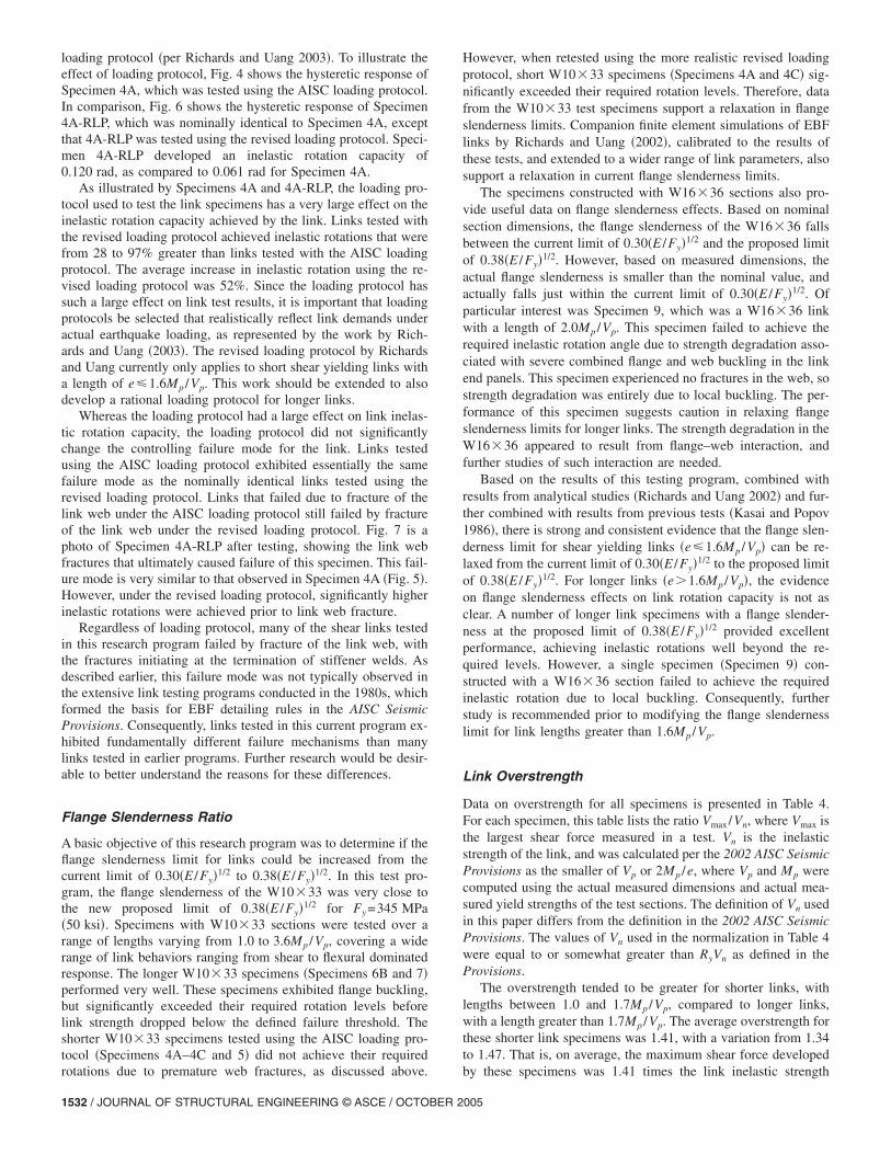
Data on overstrength for all specimens is presented in Table 4.For each specimen, this table lists the ratio Vmax/Vn, where Vmax isthe largest shear force measured in a test. Vn is the inelasticstrength of the link, and was calculated per the 2002 AISC SeismicProvisions as the smaller of Vp or 2Mp /e, where Vp and Mp werecomputed using the actual measured dimensions and actual mea-sured yield strengths of the test sections. The definition of Vn usedin this paper differs from the definition in the 2002 AISC SeismicProvisions. The values of Vn used in the normalization in Table 4were equal to or somewhat greater than RyVn as defined in theProvisions.
The overstrength tended to be greater for shorter links, withlengths between 1.0 and 1.7Mp /Vp, compared to longer links,with a length greater than 1.7Mp /Vp. The average overstrength forthese shorter link specimens was 1.41, with a variation from 1.34to 1.47. That is, on average, the maximum shear force developed
by these specimens was 1.41 times the link inelastic strength005
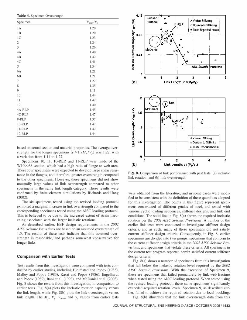
based on actual section and material properties. The average over-strength for the longer specimens �e�1.7Mp /Vp� was 1.22, witha variation from 1.11 to 1.27.
Specimens 10, 11, 10-RLP, and 11-RLP were made of theW10�68 section, which had a high ratio of flange to web area.These four specimens were expected to develop large shear resis-tance in the flanges, and therefore, greater overstrength comparedto the other specimens. However, these specimens did not showunusually large values of link overstrength compared to otherspecimens in the same link length category. These results wereconfirmed by finite element simulations by Richards and Uang�2002�.
The six specimens tested using the revised loading protocolexhibited a marginal increase in link overstrength compared to thecorresponding specimens tested using the AISC loading protocol.This is believed to be due to the increased extent of strain hard-ening associated with the larger inelastic rotations.
As described earlier, EBF design requirements in the 2002AISC Seismic Provisions are based on an assumed overstrength of1.5. The results of these tests indicate that this assumed over-strength is reasonable, and perhaps somewhat conservative forlonger links.
Comparison with Earlier Tests
Test results from this investigation were compared with tests con-ducted by earlier studies, including Hjelmstad and Popov �1983�,Malley and Popov �1983�, Kasai and Popov �1986�, Engelhardtand Popov �1989�, Itani et al. �1998�, and McDaniel et al. �2003�.Fig. 8 shows the results from this investigation, in comparison toearlier tests. Fig. 8�a� plots the inelastic rotation capacity versusthe link length, while Fig. 8�b� plots the link overstrength versus
Table 4. Specimen Overstrength
Specimen Vmax/Vn
1A 1.20
1B 1.20
1C 1.23
2 1.24
3 1.26
4A 1.40
4B 1.42
4C 1.41
5 1.34
6A 1.21
6B 1.21
7 1.27
8 1.35
9 1.11
10 1.44
11 1.42
12 1.40
4A-RLP 1.45
4C-RLP 1.47
8-RLP 1.37
10-RLP 1.47
11-RLP 1.42
12-RLP 1.44
link length. The Mp, Vp, Vmax, and �p values from earlier tests
JOURNAL
were obtained from the literature, and in some cases were modi-fied to be consistent with the definition of these quantities adoptedfor this investigation. The points in this figure represent speci-mens constructed of different grades of steel, and tested withvarious cyclic loading sequences, stiffener designs, and link endconditions. The solid line in Fig. 8�a� shows the required inelasticrotation per the 2002 AISC Seismic Provisions. A number of theearlier link tests were conducted to investigate stiffener designcriteria, and as such, many of these specimens did not satisfycurrent stiffener design criteria. Consequently, in Fig. 8, earlierspecimens are divided into two groups: specimens that conform tothe current stiffener design criteria in the 2002 AISC Seismic Pro-visions, and specimens that violate these criteria. All specimens inthe current test program reported herein satisfied current stiffenerdesign criteria.
Fig. 8�a� shows a number of specimens from this investigationthat fall below the inelastic rotation level required by the 2002AISC Seismic Provisions. With the exception of Specimen 9,these are specimens that failed prematurely by link web fracturewhen tested using the AISC loading protocol. When tested usingthe revised loading protocol, these same specimens significantlyexceeded required rotation levels. Specimen 9, as described ear-lier, failed to achieve the required rotation due to local buckling.
Fig. 8. Comparison of link performance with past tests: �a� inelasticlink rotation; and �b� link overstrength
Fig. 8�b� illustrates that the link overstrength data from this
OF STRUCTURAL ENGINEERING © ASCE / OCTOBER 2005 / 1533
investigation is similar to that from earlier tests. The effect ofchange in material from A36 steel, used in many of the earliertests, to A992 steel, used in the tests in this experimental program,on the link overstrength appears to be minimal. It is also apparentfrom Fig. 8�b� that intermediate length links in the range near2Mp /Vp experience somewhat less overstrength than very short orvery long links. This has been attributed to moment–shear inter-action in strain-hardened intermediate length links �Engelhardtand Popov 1989�.
Recent tests conducted by Itani et al. �1998� and McDaniel etal. �2003� exhibited significantly greater overstrength comparedto other tests. These tests differed from the others in that thespecimens were built-up links with a larger section and differentcross-section proportions than rolled W-shapes typically used forlinks in EBFs. Further, these links were also very short. Analysisby Richards and Uang �2002� suggest these links experiencedunusually high overstrength because of their very short lengthcombined with the heavy flanges used in these built-up sections,which permitted the flanges to develop significant shear. Thus,based on the data plotted in Fig. 8�b�, it appears that the over-strength factor of 1.5, which forms the basis for the 2002 AISCSeismic Provisions, is reasonable for links constructed of typicalrolled W-shapes. However, for short links constructed of built-upshapes with heavy flanges, a higher overstrength factor, on theorder of about 1.75–2.0, may be appropriate.
Conclusions
This paper presented data from a test program on the cyclic load-ing performance of EBF links made of ASTM A992 steel. Theprimary objectives of the test program were to reevaluate flangeslenderness limits and overstrength factors for links.
Test data from this program indicate that the flange slender-ness limit for shear yielding links �e�1.6Mp /Vp� can be relaxedfrom the current limit of 0.30�E /Fy�1/2 to 0.38�E /Fy�1/2. This ob-servation is supported by companion analytical studies and byresults from previous tests. For longer links �e�1.6Mp /Vp�, theexperimental evidence on flange slenderness effects is not asclear, and further investigation is needed before modifications tothe flange slenderness limit can be recommended.
The ASTM A992 rolled W-shape links tested in this programexhibited overstrength factors ranging from 1.11 to 1.47, with anoverall average of 1.35. When considering only shear yieldinglinks, the average overstrength factor was 1.41. Sections withhigh ratios of flange to web areas did not exhibit unusually highoverstrength factors, at least within the range of flange to webarea ratios typical of rolled W-shapes. The overstrength factor of1.5, which forms the basis for EBF design requirements in the2002 AISC Seismic Provisions, appears reasonable for links con-structed of typical rolled W-shapes. However, based on experi-mental and analytical results reported by others, for very shortlinks constructed of built-up shapes with heavy flanges, a higheroverstrength factor may be appropriate.
A number of shear link specimens tested in this program usingthe current AISC loading protocol failed to achieve required in-elastic rotation levels due to fracture of the link web. These frac-tures initiated at terminations of stiffener to link web fillet welds.This type of fracture has not typically been observed in earlierlink tests reported in the literature. Replicates of these specimenswere retested using a recently developed revised loading protocolfor shear links. All link specimens tested using the revised loading
protocol achieved the inelastic rotations required in the 20021534 / JOURNAL OF STRUCTURAL ENGINEERING © ASCE / OCTOBER 2
AISC Seismic Provisions. In fact, these specimens developed in-elastic rotations on the order of 10–50% greater than those re-quired in the 2002 AISC Seismic Provisions.
Link web fracture can be delayed and link rotation capacitycan be enhanced by increasing the distance from the k-line of therolled link section to the termination of the stiffener to link webfillet weld. Based on the test results, it is recommended that stiff-ener welds be terminated a distance of at least 5*tw from the k-lineof the link section, where tw is the link web thickness.
Results of this test program clearly show that the loading pro-tocol used to test EBF links has a very large effect on the inelasticrotation achieved by the links. Since the loading protocol has sucha large effect on link test results, it is important that loadingprotocols be selected that realistically reflect link demands underactual earthquake loading, as represented by the revised loadingprotocol recently developed by Richards and Uang �2003�. Therevised loading protocol by Richards and Uang currently onlyapplies to short shear yielding links with a length of e�1.6Mp /Vp. This work should be extended to also develop arational loading protocol for longer links with a length greaterthan 1.6Mp /Vp.
Acknowledgments
The writers gratefully acknowledge primary funding provided forthis project by the American Institute of Steel Construction�AISC� and supplemental funding from the National ScienceFoundation �Grant No. CMS-0000031�. The writers would liketo particularly thank Tom Schlafly of AISC for his support andassistance throughout this project. The experimental workreported herein was conducted as part of a joint project withcompanion analytical studies at the University of California atSan Diego �UCSD�. The writers thank Professor Chia-Ming Uangand Paul Richards at UCSD for their assistance, participation, andcollaboration in this project. The writers also thank James Malley,Subhash Goel, and Tom Sabol for their assistance and advice onthis project.
References
American Institute of Steel Construction �AISC�. �1999�. Load and resis-tance factor design specification for structural steel buildings, AISC,Chicago.
American Institute of Steel Construction �AISC�. �2002�. “Seismic pro-visions for structural steel buildings.” ANSI/AISC 341-02, AISC, Chi-cago.
Engelhardt, M. D., and Popov, E. P. �1989�. “Behavior of long links ineccentrically braced frames.” Rep. No. UCB/EERC-89/01, EarthquakeEngineering Research Center, Univ. of California at Berkeley, Rich-mond, Calif.
Hjelmstad, K. D., and Popov, E. P. �1983�. “Seismic behavior of activebeam link in eccentrically braced frames.” Rep. No. UCB/EERC-83/15, Earthquake Engineering Research Center, Univ. of California atBerkeley, Richmond, Calif.
Itani, A., Douglas, B. M., and El-Fass, S. �1998�. “Cyclic behavior ofshear links in retrofitted Richmond-San Rafael Bridge towers.” Proc.,1st World Congress on Structural Engineering—San Francisco, PaperNo. T155-3, Elsevier, New York.
Kasai, K., and Popov, E. P. �1986�. “A study of seismically resistanteccentrically braced frames.” Rep. No. UCB/EERC-86/01, EarthquakeEngineering Research Center, Univ. of California at Berkeley, Rich-mond, Calif.
Krawinkler, H., Gupta, A., Medina, R., and Luco, N. �2000�. “Loading
005

histories for seismic performance testing of SMRF components andassemblies.” Rep. No. SAC/BD–00/10, SAC Joint Venture.
Malley, J. O., and Popov, E. P. �1983�. “Design considerations for shearlinks in eccentrically braced frames.” Rep. No. UCB/EERC–83/24,Earthquake Engineering Research Center, Univ. of California at Ber-keley, Richmond, Calif.
McDaniel, C. C., Uang, C.-M., and Seible, F. �2003�. “Cyclic testing ofbuilt-up steel shear links for the new Bay Bridge.” J. Struct. Eng.,129�6�, 801–809.
Popov, E. P., and Engelhardt, M. D. �1988�. “Seismic eccentrically braced
JOURNAL
frames.” J. Constr. Steel Res., 10, 321–354.Richards, P., and Uang, C.-M. �2002�. “Evaluation of rotation capacity
and overstrength of links in eccentrically braced frames �Phase 1�.”Rep. No. SSRP–2002/18, Dept. of Structural Engineering, Univ. of
California at San Diego, La Jolla, Calif.Richards, P., and Uang, C. M. �2003�. “Development of testing protocol
for short links in eccentrically braced frames.” Rep. No. SSRP–2003/08, Dept. of Structural Engineering, Univ. of California at San Diego,
La Jolla, Calif.OF STRUCTURAL ENGINEERING © ASCE / OCTOBER 2005 / 1535
Copyright © 2022 FDOKUMEN