Experimental investigation on a base isolation system incorporating steel–Teflon sliders and...
18
EARTHQUAKE ENGINEERING AND STRUCTURAL DYNAMICS Earthquake Engng Struct. Dyn. 2008; 37:225–242 Published online 21 September 2007 in Wiley InterScience (www.interscience.wiley.com). DOI: 10.1002/eqe.753 Experimental investigation on a base isolation system incorporating steel–Teflon sliders and pressurized fluid viscous spring dampers Stefano Sorace 1, ∗,† , Gloria Terenzi 2 , Georges Magonette 3 and Francisco J. Molina 3 1 Department of Civil Engineering, University of Udine, Via delle Scienze 208, 33100 Udine, Italy 2 Department of Civil Engineering, University of Florence, Via di S. Marta 3, 50139 Florence, Italy 3 European Commission, Joint Research Centre, IPSC, ELSA Laboratory, 21020 Ispra (Varese), Italy SUMMARY An experimental investigation on a base isolation system incorporating stainless steel–Teflon bearings as sliders, and pressurized fluid viscous spring dampers, is presented in this paper. In the system examined, dampers are connected to the base floor of an isolated building to provide the desired passive control of response in the superstructure, as well as to guarantee that it re-centres completely after the termination of a seismic action. Two types of experiments were conducted: sinusoidal and random cyclic tests, and a pseudodynamic test in ‘substructured’ configuration. The cyclic tests were aimed at characterizing what follows: the hysteretic and strain-rate-dependent response of the considered highly non-linear spring dampers; the normal pressure- and strain-rate-dependent frictional behaviour of steel–Teflon bearings, manufactured in compliance with the latest standards for this class of sliders; and the combined response of their assembly. The pseudodynamic test simulated the installation of the protection system at the base of a 2:3-scale three-storey steel frame structure, already tested in unprotected conditions by an earlier experimental campaign. Among other findings, the results of the performed tests, as well as of relevant mechanical interpretation and numerical simulation analyses, confirmed the linear additive combination of the dissipative actions of spring dampers and sliders in this mixed installation, and the high protective performance of the considered base isolation/supplemental damping system in a realistic earthquake simulation. Copyright 2007 John Wiley & Sons, Ltd. Received 30 January 2007; Revised 23 June 2007; Accepted 16 July 2007 KEY WORDS: seismic protection; base isolation; supplemental damping; sliding bearings; fluid viscous devices; cyclic tests; pseudodynamic tests; substructuring ∗ Correspondence to: Stefano Sorace, Department of Civil Engineering, University of Udine, Via delle Scienze 208, 33100 Udine, Italy. † E-mail: [email protected] Contract/grant sponsor: European Commission; contract/grant number: HPRI-CT-1999-00059 Copyright 2007 John Wiley & Sons, Ltd.
Transcript of Experimental investigation on a base isolation system incorporating steel–Teflon sliders and...
EARTHQUAKE ENGINEERING AND STRUCTURAL DYNAMICSEarthquake Engng Struct. Dyn. 2008; 37:225–242Published online 21 September 2007 in Wiley InterScience (www.interscience.wiley.com). DOI: 10.1002/eqe.753
Experimental investigation on a base isolation system incorporatingsteel–Teflon sliders and pressurized fluid viscous spring dampers
Stefano Sorace1,∗,†, Gloria Terenzi2, Georges Magonette3 and Francisco J. Molina3
1Department of Civil Engineering, University of Udine, Via delle Scienze 208, 33100 Udine, Italy2Department of Civil Engineering, University of Florence, Via di S. Marta 3, 50139 Florence, Italy3European Commission, Joint Research Centre, IPSC, ELSA Laboratory, 21020 Ispra (Varese), Italy
SUMMARY
An experimental investigation on a base isolation system incorporating stainless steel–Teflon bearings assliders, and pressurized fluid viscous spring dampers, is presented in this paper. In the system examined,dampers are connected to the base floor of an isolated building to provide the desired passive control ofresponse in the superstructure, as well as to guarantee that it re-centres completely after the terminationof a seismic action. Two types of experiments were conducted: sinusoidal and random cyclic tests, anda pseudodynamic test in ‘substructured’ configuration. The cyclic tests were aimed at characterizingwhat follows: the hysteretic and strain-rate-dependent response of the considered highly non-linear springdampers; the normal pressure- and strain-rate-dependent frictional behaviour of steel–Teflon bearings,manufactured in compliance with the latest standards for this class of sliders; and the combined responseof their assembly. The pseudodynamic test simulated the installation of the protection system at the baseof a 2:3-scale three-storey steel frame structure, already tested in unprotected conditions by an earlierexperimental campaign. Among other findings, the results of the performed tests, as well as of relevantmechanical interpretation and numerical simulation analyses, confirmed the linear additive combinationof the dissipative actions of spring dampers and sliders in this mixed installation, and the high protectiveperformance of the considered base isolation/supplemental damping system in a realistic earthquakesimulation. Copyright q 2007 John Wiley & Sons, Ltd.
Received 30 January 2007; Revised 23 June 2007; Accepted 16 July 2007
KEY WORDS: seismic protection; base isolation; supplemental damping; sliding bearings; fluid viscousdevices; cyclic tests; pseudodynamic tests; substructuring
∗Correspondence to: Stefano Sorace, Department of Civil Engineering, University of Udine, Via delle Scienze 208,33100 Udine, Italy.
†E-mail: [email protected]
Contract/grant sponsor: European Commission; contract/grant number: HPRI-CT-1999-00059
Copyright q 2007 John Wiley & Sons, Ltd.
226 S. SORACE ET AL.
1. INTRODUCTION
Several types of base isolation systems have been developed in the field of advanced seis-mic protection of structures during the past 30 years. Some of them are now widely usedin practical applications, and especially in new design and retrofit of strategic buildings, suchas hospitals, barracks, firehouses, emergency management headquarters, etc. [1, 2]. In additionto meeting the basic need to uncouple foundation and superstructure motions under a seismicaction, these technologies must also supply the damping force required to constrain base dis-placements within acceptable limits, so as to ensure adequate performance control and a rea-sonable size for the constituting devices and the service lines crossing the base-isolation plane[2–4]. At the same time, excessive damping must not be added, not to increase superstruc-ture response, both in terms of accelerations and interstorey drifts. Normally, the amount ofdamping can be easily calibrated by crossing the different requirements on base displacementsand superstructure response, in order to obtain the best combined performance of the protectionsystem.
Damping action can be either directly provided by the isolators, e.g. in the case of high dampingrubber bearings, lead rubber bearings and friction pendulums, or by additional viscous, fluid viscous(FV) or friction dissipaters, when the isolators almost act as pure sliders [3, 4]. Among thesecombined technologies, a BISD system coupling lubricated steel–Teflon bearings and pressurizedsilicone FV spring dampers has been investigated for several years by the first two authors of thispaper. In particular, the experimental characterization of FV devices, the analytical and numericalmodelling of their response as well as of steel–Teflon sliders’, and the definition of design criteriafor an optimal implementation of the system, were developed within these studies [5–8]. At anearlier stage, the system performance was also verified experimentally by mounting the system ona 1:4-scale steel mock-up tested with a dynamic vibration campaign [6].
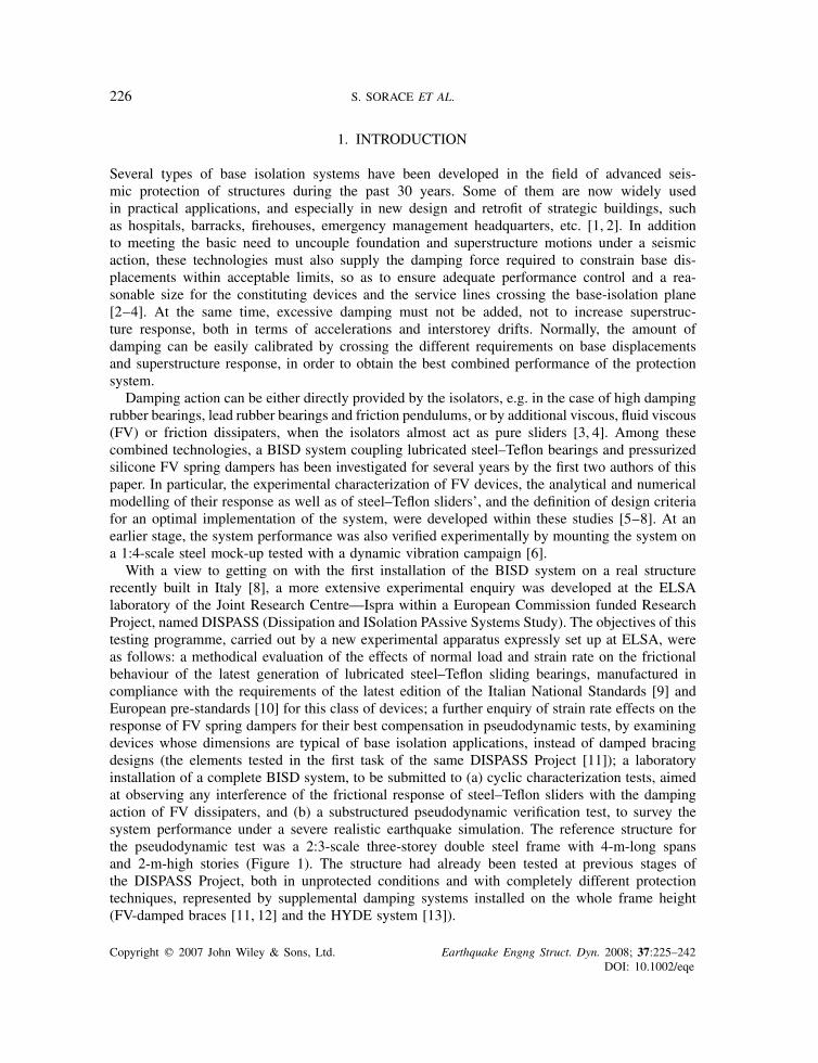
With a view to getting on with the first installation of the BISD system on a real structurerecently built in Italy [8], a more extensive experimental enquiry was developed at the ELSAlaboratory of the Joint Research Centre—Ispra within a European Commission funded ResearchProject, named DISPASS (Dissipation and ISolation PAssive Systems Study). The objectives of thistesting programme, carried out by a new experimental apparatus expressly set up at ELSA, wereas follows: a methodical evaluation of the effects of normal load and strain rate on the frictionalbehaviour of the latest generation of lubricated steel–Teflon sliding bearings, manufactured incompliance with the requirements of the latest edition of the Italian National Standards [9] andEuropean pre-standards [10] for this class of devices; a further enquiry of strain rate effects on theresponse of FV spring dampers for their best compensation in pseudodynamic tests, by examiningdevices whose dimensions are typical of base isolation applications, instead of damped bracingdesigns (the elements tested in the first task of the same DISPASS Project [11]); a laboratoryinstallation of a complete BISD system, to be submitted to (a) cyclic characterization tests, aimedat observing any interference of the frictional response of steel–Teflon sliders with the dampingaction of FV dissipaters, and (b) a substructured pseudodynamic verification test, to survey thesystem performance under a severe realistic earthquake simulation. The reference structure forthe pseudodynamic test was a 2:3-scale three-storey double steel frame with 4-m-long spansand 2-m-high stories (Figure 1). The structure had already been tested at previous stages ofthe DISPASS Project, both in unprotected conditions and with completely different protectiontechniques, represented by supplemental damping systems installed on the whole frame height(FV-damped braces [11, 12] and the HYDE system [13]).
Copyright q 2007 John Wiley & Sons, Ltd. Earthquake Engng Struct. Dyn. 2008; 37:225–242DOI: 10.1002/eqe
EXPERIMENTAL INVESTIGATION ON A BASE ISOLATION SYSTEM 227
Figure 1. Reference steel structure.
The design of the BISD system for its simulated application to the mock-up structure; thecharacteristics of the experimental apparatus for the cyclic tests on the BISD components andtheir assemblies, as well as for the pseudodynamic test on the overall system; a descriptionof the substructured pseudodynamic testing method; and the results of the various stages ofthe experimental programme, relevant elaborations, interpretation and numerical simulations, aredetailed in the next sections.
2. DESIGN OF FV SPRING DAMPERS AND STEEL–TEFLON SLIDERS
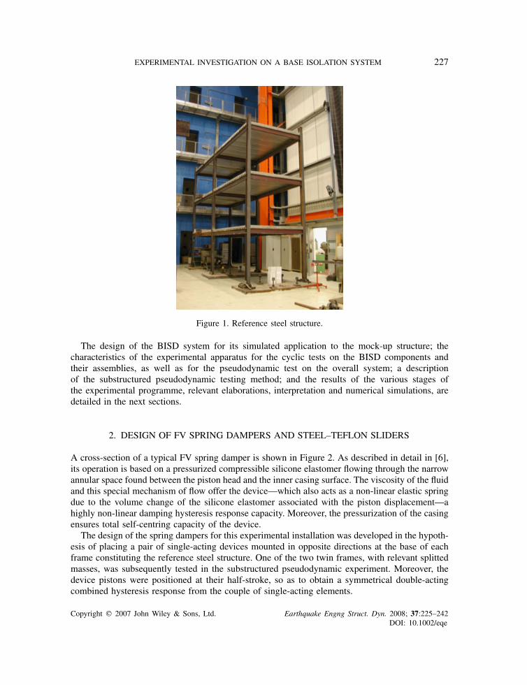
A cross-section of a typical FV spring damper is shown in Figure 2. As described in detail in [6],its operation is based on a pressurized compressible silicone elastomer flowing through the narrowannular space found between the piston head and the inner casing surface. The viscosity of the fluidand this special mechanism of flow offer the device—which also acts as a non-linear elastic springdue to the volume change of the silicone elastomer associated with the piston displacement—ahighly non-linear damping hysteresis response capacity. Moreover, the pressurization of the casingensures total self-centring capacity of the device.
The design of the spring dampers for this experimental installation was developed in the hypoth-esis of placing a pair of single-acting devices mounted in opposite directions at the base of eachframe constituting the reference steel structure. One of the two twin frames, with relevant splittedmasses, was subsequently tested in the substructured pseudodynamic experiment. Moreover, thedevice pistons were positioned at their half-stroke, so as to obtain a symmetrical double-actingcombined hysteresis response from the couple of single-acting elements.
Copyright q 2007 John Wiley & Sons, Ltd. Earthquake Engng Struct. Dyn. 2008; 37:225–242DOI: 10.1002/eqe
228 S. SORACE ET AL.
Connection plate
Slide-way ring
Inner casing
Piston
Silicone fluid
Figure 2. Section of a fluid viscous spring damper.
The damping coefficient c for each device was determined by the design procedure formulatedin [6], assuming a target loss factor � = 0.5 for the system (which corresponds to an equivalentviscous damping ratio � = 0.25). The resulting value was c= 6.1 kN(s/mm)�, which characterizesthe analytical expression of the damping restoring force Fd [6, 14, 15]:
Fd(t) = c · |v(t)|� sign(v(t)) (1)
where v(t) is the piston velocity, a function of the time variable t , and � is a fractional exponent—ranging from 0.1 to 0.2 for this type of devices [6]—in this case equal to 0.15.
The second design step consisted in fixing the fundamental vibration frequency fis of the steelstructure in base-isolated conditions. This was obtained by assuming a rounded value 3 for theffb/ fis ratio, where ffb is the fundamental vibration frequency in fixed-base conditions, equal to2.27Hz. This produced a fis value of 0.704Hz. Then, the ‘spring’ characteristics of each FV elementwere defined as follows: k2 = 4�2 · f 2is ·Mi = 0.178 kN/mm, where Mi is the building mass relevantto each device, equal to 9.11 kg; and k1 = 15k2 = 2.67 kN/mm. The static pre-load F0 appliedin the manufacturing phase was fixed with the empirical formula [6]: F0 = k2 · dmax/5= 7.1 kN,where dmax is the maximum device stroke, set as equal to 200mm to obtain a ±100mm operationaldisplacement after the initial half-stroke positioning of the piston. The k1, k2 and F0 values abovealso define the non-linear elastic restoring force Fe of the spring dampers [6, 14]:
Fe(t) = k2 · d(t) + (k1 − k2) · d(t)
[1 + |k1x(t)/F0|5]1/5 (2)
where d is the piston displacement. It can be noted that the combination of relations (1)—whichdefines a rounded rectangular shape of the damping response cycles, resulting from the very lowvalues of the � exponent mentioned above—and (2)—featuring a bilinear response of the springcomponent—produces a typical rounded parallelogram-like shape of the response cycles of thisclass of FV devices [3, 6, 14].
As a final design choice, two relatively small-sized spring dampers were selected from themanufacturer’s catalogue [16], as they provided the best approximation of the preliminary designk1, k2 and F0 values. It is worth noting that, being any pair of FV devices connected in parallelwithin a BISD system, the resulting k2, k1 and c parameters for the coupled elements are twice thevalues of each device. Thus, the global design values for the two spring dampers are as follows:k2t = 0.356 kN/mm; k1t = 5.34 kN/mm; ct = 12.2 kN(s/mm)�.
Copyright q 2007 John Wiley & Sons, Ltd. Earthquake Engng Struct. Dyn. 2008; 37:225–242DOI: 10.1002/eqe
EXPERIMENTAL INVESTIGATION ON A BASE ISOLATION SYSTEM 229
500
200
138
250
200
200
138
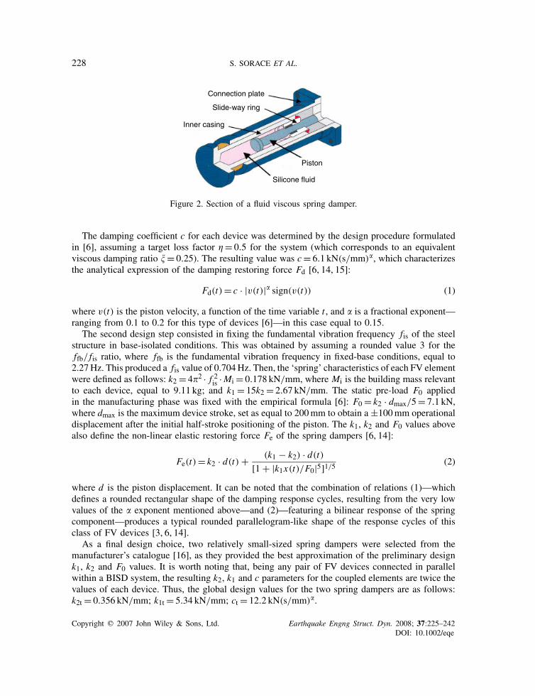
500Stainless steel plate
Austenitic steel sheet
Stainless steel plate
Lubricated Teflon disk
36
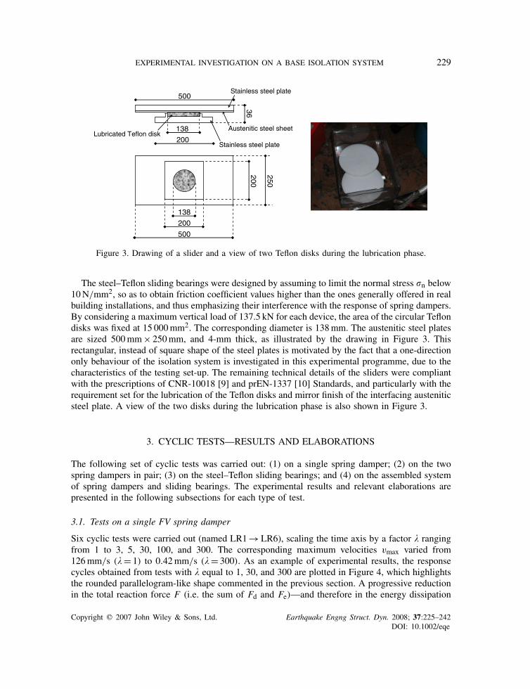
Figure 3. Drawing of a slider and a view of two Teflon disks during the lubrication phase.
The steel–Teflon sliding bearings were designed by assuming to limit the normal stress �n below10N/mm2, so as to obtain friction coefficient values higher than the ones generally offered in realbuilding installations, and thus emphasizing their interference with the response of spring dampers.By considering a maximum vertical load of 137.5 kN for each device, the area of the circular Teflondisks was fixed at 15 000mm2. The corresponding diameter is 138mm. The austenitic steel platesare sized 500mm× 250mm, and 4-mm thick, as illustrated by the drawing in Figure 3. Thisrectangular, instead of square shape of the steel plates is motivated by the fact that a one-directiononly behaviour of the isolation system is investigated in this experimental programme, due to thecharacteristics of the testing set-up. The remaining technical details of the sliders were compliantwith the prescriptions of CNR-10018 [9] and prEN-1337 [10] Standards, and particularly with therequirement set for the lubrication of the Teflon disks and mirror finish of the interfacing austeniticsteel plate. A view of the two disks during the lubrication phase is also shown in Figure 3.
3. CYCLIC TESTS—RESULTS AND ELABORATIONS
The following set of cyclic tests was carried out: (1) on a single spring damper; (2) on the twospring dampers in pair; (3) on the steel–Teflon sliding bearings; and (4) on the assembled systemof spring dampers and sliding bearings. The experimental results and relevant elaborations arepresented in the following subsections for each type of test.
3.1. Tests on a single FV spring damper
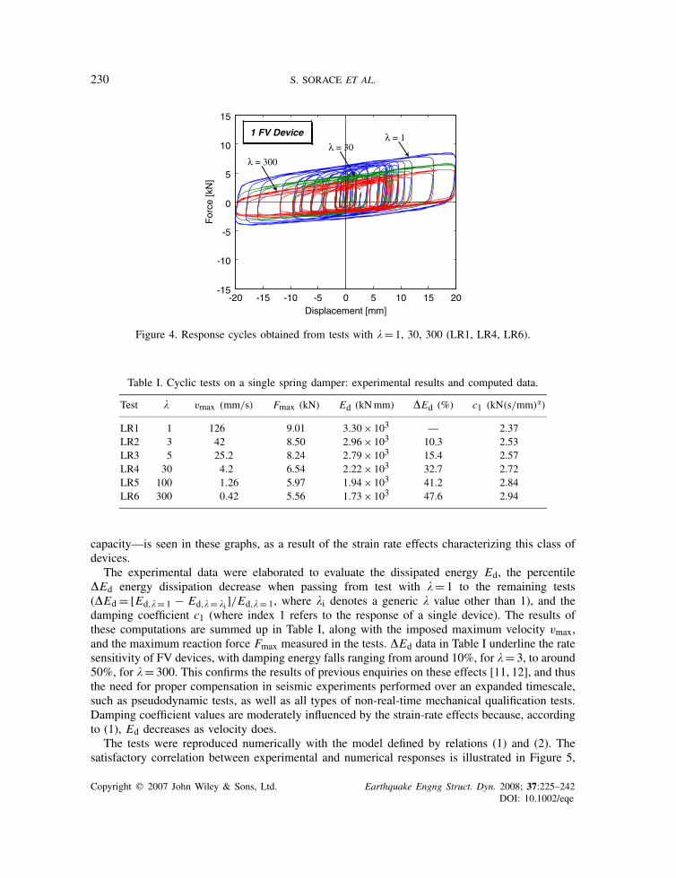
Six cyclic tests were carried out (named LR1→LR6), scaling the time axis by a factor � rangingfrom 1 to 3, 5, 30, 100, and 300. The corresponding maximum velocities vmax varied from126mm/s (� = 1) to 0.42mm/s (�= 300). As an example of experimental results, the responsecycles obtained from tests with � equal to 1, 30, and 300 are plotted in Figure 4, which highlightsthe rounded parallelogram-like shape commented in the previous section. A progressive reductionin the total reaction force F (i.e. the sum of Fd and Fe)—and therefore in the energy dissipation
Copyright q 2007 John Wiley & Sons, Ltd. Earthquake Engng Struct. Dyn. 2008; 37:225–242DOI: 10.1002/eqe
230 S. SORACE ET AL.
-20 -15 -10 -5 0 5 10 15 20-15
-10
-5
0
5
10
15
For
ce [k
N]
Displacement [mm]
λ = 1λ = 30
λ = 300
1 FV Device
Figure 4. Response cycles obtained from tests with �= 1, 30, 300 (LR1, LR4, LR6).
Table I. Cyclic tests on a single spring damper: experimental results and computed data.
Test � vmax (mm/s) Fmax (kN) Ed (kNmm) �Ed (%) c1 (kN(s/mm)�)
LR1 1 126 9.01 3.30× 10³ — 2.37LR2 3 42 8.50 2.96× 10³ 10.3 2.53LR3 5 25.2 8.24 2.79× 10³ 15.4 2.57LR4 30 4.2 6.54 2.22× 10³ 32.7 2.72LR5 100 1.26 5.97 1.94× 10³ 41.2 2.84LR6 300 0.42 5.56 1.73× 10³ 47.6 2.94
capacity—is seen in these graphs, as a result of the strain rate effects characterizing this class ofdevices.
The experimental data were elaborated to evaluate the dissipated energy Ed, the percentile�Ed energy dissipation decrease when passing from test with � = 1 to the remaining tests(�Ed =[Ed,�= 1 − Ed,�= �i]/Ed,�= 1, where �i denotes a generic � value other than 1), and thedamping coefficient c1 (where index 1 refers to the response of a single device). The results ofthese computations are summed up in Table I, along with the imposed maximum velocity vmax,and the maximum reaction force Fmax measured in the tests. �Ed data in Table I underline the ratesensitivity of FV devices, with damping energy falls ranging from around 10%, for � = 3, to around50%, for � = 300. This confirms the results of previous enquiries on these effects [11, 12], and thusthe need for proper compensation in seismic experiments performed over an expanded timescale,such as pseudodynamic tests, as well as all types of non-real-time mechanical qualification tests.Damping coefficient values are moderately influenced by the strain-rate effects because, accordingto (1), Ed decreases as velocity does.
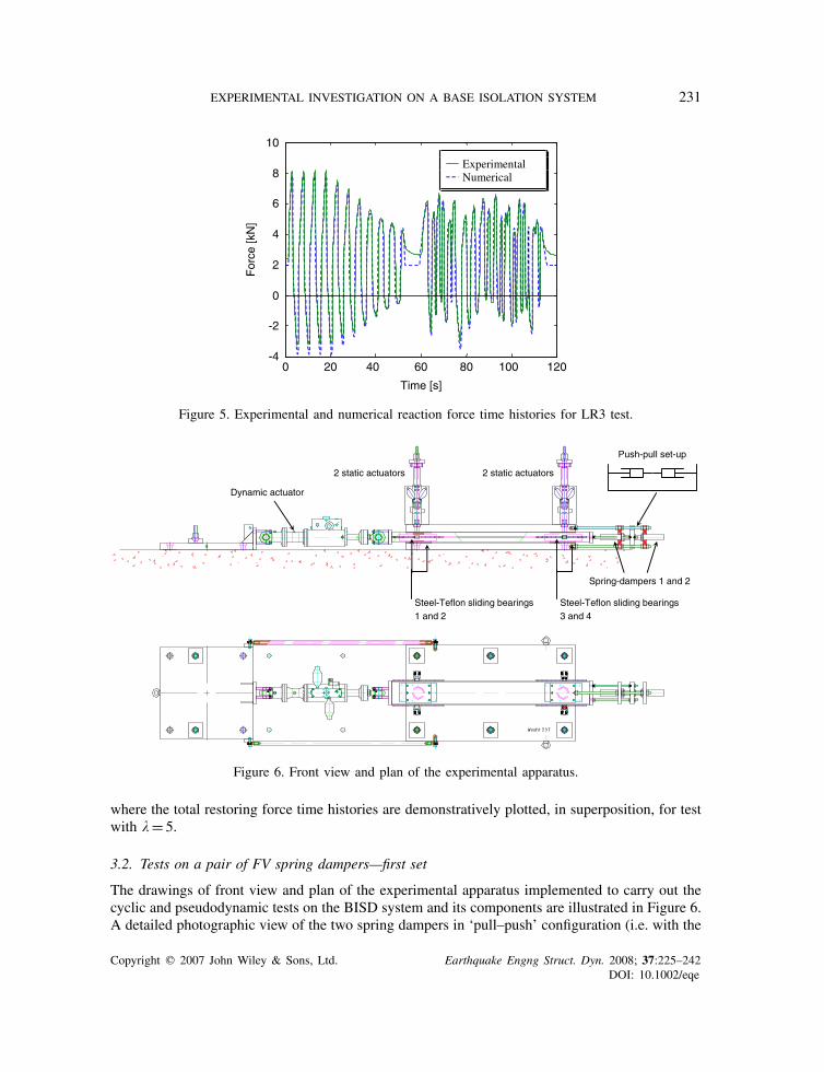
The tests were reproduced numerically with the model defined by relations (1) and (2). Thesatisfactory correlation between experimental and numerical responses is illustrated in Figure 5,
Copyright q 2007 John Wiley & Sons, Ltd. Earthquake Engng Struct. Dyn. 2008; 37:225–242DOI: 10.1002/eqe
EXPERIMENTAL INVESTIGATION ON A BASE ISOLATION SYSTEM 231
0 20 40 60 80 100 120-4
-2
0
2
4
6
8
10
Time [s]
For
ce [k
N]
ExperimentalNumerical
Figure 5. Experimental and numerical reaction force time histories for LR3 test.
Spring-dampers 1 and 2
Push-pull set-up
Dynamic actuator
2 static actuators 2 static actuators
Steel-Teflon sliding bearings1 and 2
Steel-Teflon sliding bearings3 and 4
Figure 6. Front view and plan of the experimental apparatus.
where the total restoring force time histories are demonstratively plotted, in superposition, for testwith � = 5.
3.2. Tests on a pair of FV spring dampers—first set
The drawings of front view and plan of the experimental apparatus implemented to carry out thecyclic and pseudodynamic tests on the BISD system and its components are illustrated in Figure 6.A detailed photographic view of the two spring dampers in ‘pull–push’ configuration (i.e. with the
Copyright q 2007 John Wiley & Sons, Ltd. Earthquake Engng Struct. Dyn. 2008; 37:225–242DOI: 10.1002/eqe
232 S. SORACE ET AL.
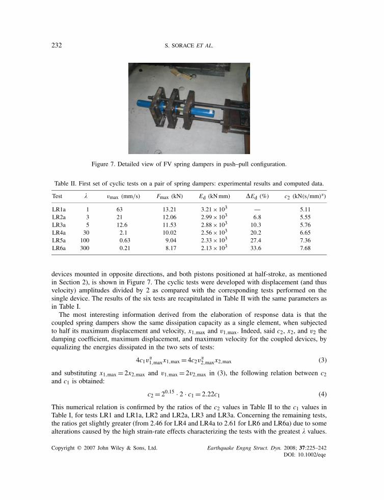
Figure 7. Detailed view of FV spring dampers in push–pull configuration.
Table II. First set of cyclic tests on a pair of spring dampers: experimental results and computed data.
Test � vmax (mm/s) Fmax (kN) Ed (kNmm) �Ed (%) c2 (kN(s/mm)�)
LR1a 1 63 13.21 3.21× 10³ — 5.11LR2a 3 21 12.06 2.99× 10³ 6.8 5.55LR3a 5 12.6 11.53 2.88× 10³ 10.3 5.76LR4a 30 2.1 10.02 2.56× 10³ 20.2 6.65LR5a 100 0.63 9.04 2.33× 10³ 27.4 7.36LR6a 300 0.21 8.17 2.13× 10³ 33.6 7.68
devices mounted in opposite directions, and both pistons positioned at half-stroke, as mentionedin Section 2), is shown in Figure 7. The cyclic tests were developed with displacement (and thusvelocity) amplitudes divided by 2 as compared with the corresponding tests performed on thesingle device. The results of the six tests are recapitulated in Table II with the same parameters asin Table I.
The most interesting information derived from the elaboration of response data is that thecoupled spring dampers show the same dissipation capacity as a single element, when subjectedto half its maximum displacement and velocity, x1,max and v1,max. Indeed, said c2, x2, and v2 thedamping coefficient, maximum displacement, and maximum velocity for the coupled devices, byequalizing the energies dissipated in the two sets of tests:
4c1v�1,maxx1,max = 4c2v
�2,maxx2,max (3)
and substituting x1,max = 2x2,max and v1,max = 2v2,max in (3), the following relation between c2and c1 is obtained:
c2 = 20.15 · 2 · c1 = 2.22c1 (4)
This numerical relation is confirmed by the ratios of the c2 values in Table II to the c1 values inTable I, for tests LR1 and LR1a, LR2 and LR2a, LR3 and LR3a. Concerning the remaining tests,the ratios get slightly greater (from 2.46 for LR4 and LR4a to 2.61 for LR6 and LR6a) due to somealterations caused by the high strain-rate effects characterizing the tests with the greatest � values.
Copyright q 2007 John Wiley & Sons, Ltd. Earthquake Engng Struct. Dyn. 2008; 37:225–242DOI: 10.1002/eqe
EXPERIMENTAL INVESTIGATION ON A BASE ISOLATION SYSTEM 233
0 50 100 150 200 250 3001
1.1
1.2
1.3
1.4
1.5
1.6
1.7
1.8
1.9
2
Bλi
2 FV Devices
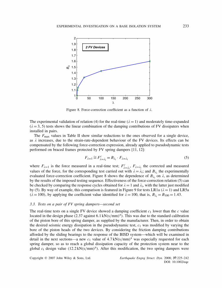
Figure 8. Force-correction coefficient as a function of �.
The experimental validation of relation (4) for the real-time (� = 1) and moderately time-expanded(� = 3, 5) tests shows the linear combination of the damping contributions of FV dissipaters wheninstalled in pairs.
The Fmax values in Table II show similar reductions to the ones observed for a single device,as � increases, due to the strain-rate-dependent behaviour of the FV devices. Its effects can becompensated by the following force-correction expression, already applied to pseudodynamic testsperformed on braced frames protected by FV spring dampers [11, 12]:
F�=1∼= Fc
�=�i= B�i · F�=�i (5)
where F�=1 is the force measured in a real-time test; Fc�=�i
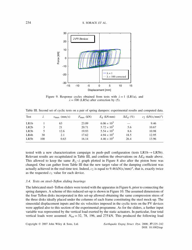
, F�=�i the corrected and measuredvalues of the force, for the corresponding test carried out with � = �i; and B�i the experimentallyevaluated force-correction coefficient. Figure 8 shows the dependence of B�i on �, as determinedby the results of the imposed testing sequence. Effectiveness of the force-correction relation (5) canbe checked by comparing the response cycles obtained for � = 1 and �i, with the latter just modifiedby (5). By way of example, this comparison is featured in Figure 9 for tests LR1a (� = 1) and LR5a(� = 100), by applying the coefficient value identified for � = 100, that is, B�i = B100 = 1.43.
3.3. Tests on a pair of FV spring dampers—second set
The real-time tests on a single FV device showed a damping coefficient c1 lower than the c valuelocated in the design phase (2.37 against 6.1 kN(s/mm)�). This was due to the standard calibrationof the piston bore of this spring damper, as supplied by the manufacturer. Then, in order to obtainthe desired seismic energy dissipation in the pseudodynamic test, c1 was modified by varying thebore of the piston heads of the two devices. By considering the friction damping contributionsafforded by the sliding bearings to the response of the BISD system—which will be examined indetail in the next sections—a new c1 value of 4.7 kN(s/mm)� was especially requested for eachspring damper, so as to reach a global dissipation capacity of the protection system near to theglobal ct design value (12.2 kN(s/mm)�). After this modification, the two spring dampers were
Copyright q 2007 John Wiley & Sons, Ltd. Earthquake Engng Struct. Dyn. 2008; 37:225–242DOI: 10.1002/eqe
234 S. SORACE ET AL.
-15 -10 -5 0 5 10 15-30
-20
-10
0
10
20
30
For
ce [k
N]
Displacement [mm]
λ = 1λ = 100 corrected
2 FV Devices
Figure 9. Response cycles obtained from tests with �= 1 (LR1a), and�= 100 (LR5a) after correction by (5).
Table III. Second set of cyclic tests on a pair of spring dampers: experimental results and computed data.
Test � vmax (mm/s) Fmax (kN) Ed (kNmm) �Ed (%) c2 (kN(s/mm)�)
LR1b 1 63 23.09 6.06× 10³ — 9.46LR2b 3 21 20.71 5.72× 10³ 5.6 10.67LR3b 5 12.6 19.93 5.54× 10³ 8.6 10.98LR4b 30 2.1 17.62 4.94× 10³ 18.5 12.95LR5b 100 0.63 16.14 4.46× 10³ 26.4 13.96
tested with a new characterization campaign in push–pull configuration (tests LR1b→LR5b).Relevant results are recapitulated in Table III, and confirm the observations on �Ed made above.This allowed to keep the same B�i–� graph plotted in Figure 8 also after the piston bore waschanged. One can gather from Table III that the new target value of the damping coefficient wasactually achieved in the real-time test. Indeed, c2 is equal to 9.46 kN(s/mm)�, that is, exactly twiceas the requested c1 value for each device.
3.4. Tests on steel–Teflon sliding bearings
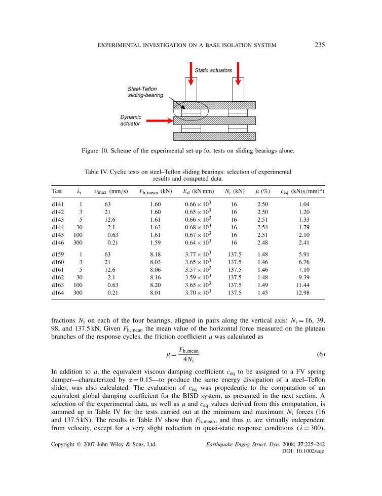
The lubricated steel–Teflon sliders were tested with the apparatus in Figure 6, prior to connecting thespring dampers. A scheme of this reduced set-up is shown in Figure 10. The assumed dimensions ofthe four Teflon disks incorporated in this set-up allowed obtaining the same compression stress ofthe three disks ideally placed under the columns of each frame constituting the steel mock-up. Thesinusoidal displacement inputs and the six velocities imposed in the cyclic tests on the FV deviceswere applied also to this section of the experimental programme. As for the sliders, a further inputvariable was represented by the vertical load exerted by the static actuators. In particular, four totalvertical loads were assumed: Ntot = 32, 78, 196, and 275 kN. This produced the following load
Copyright q 2007 John Wiley & Sons, Ltd. Earthquake Engng Struct. Dyn. 2008; 37:225–242DOI: 10.1002/eqe
EXPERIMENTAL INVESTIGATION ON A BASE ISOLATION SYSTEM 235
Static actuators
sliding-bearingSteel-Teflon
Dynamicactuator
Figure 10. Scheme of the experimental set-up for tests on sliding bearings alone.
Table IV. Cyclic tests on steel–Teflon sliding bearings: selection of experimentalresults and computed data.
Test �i vmax (mm/s) Fh,mean (kN) Ed (kNmm) Ni (kN) � (%) ceq (kN(s/mm)�)
d141 1 63 1.60 0.66× 10³ 16 2.50 1.04d142 3 21 1.60 0.65× 10³ 16 2.50 1.20d143 5 12.6 1.61 0.66× 10³ 16 2.51 1.33d144 30 2.1 1.63 0.68× 10³ 16 2.54 1.79d145 100 0.63 1.61 0.67× 10³ 16 2.51 2.10d146 300 0.21 1.59 0.64× 10³ 16 2.48 2.41
d159 1 63 8.18 3.77× 10³ 137.5 1.48 5.91d160 3 21 8.03 3.65× 10³ 137.5 1.46 6.76d161 5 12.6 8.06 3.57× 10³ 137.5 1.46 7.10d162 30 2.1 8.16 3.59× 10³ 137.5 1.48 9.39d163 100 0.63 8.20 3.65× 10³ 137.5 1.49 11.44d164 300 0.21 8.01 3.70× 10³ 137.5 1.45 12.98
fractions Ni on each of the four bearings, aligned in pairs along the vertical axis: Ni = 16, 39,98, and 137.5 kN. Given Fh,mean the mean value of the horizontal force measured on the plateaubranches of the response cycles, the friction coefficient � was calculated as
�= Fh,mean
4Ni(6)
In addition to �, the equivalent viscous damping coefficient ceq to be assigned to a FV springdamper—characterized by � = 0.15—to produce the same energy dissipation of a steel–Teflonslider, was also calculated. The evaluation of ceq was propedeutic to the computation of anequivalent global damping coefficient for the BISD system, as presented in the next section. Aselection of the experimental data, as well as � and ceq values derived from this computation, issummed up in Table IV for the tests carried out at the minimum and maximum Ni forces (16and 137.5 kN). The results in Table IV show that Fh,mean, and thus �, are virtually independentfrom velocity, except for a very slight reduction in quasi-static response conditions (� = 300).
Copyright q 2007 John Wiley & Sons, Ltd. Earthquake Engng Struct. Dyn. 2008; 37:225–242DOI: 10.1002/eqe
236 S. SORACE ET AL.
-10 -8 -6 -4 -2 0 2 4 6 8 10-15
-10
-5
0
5
10
15
Displacement [mm]
For
ce [k
N]
v = 63 mm/s
Ntot = 275 kNNtot = 196 kNNtot = 78 kN
Ntot = 32 kN
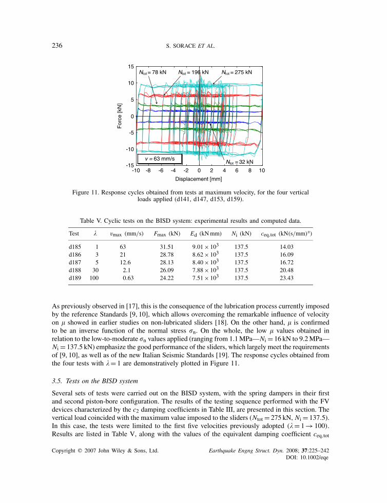
Figure 11. Response cycles obtained from tests at maximum velocity, for the four verticalloads applied (d141, d147, d153, d159).
Table V. Cyclic tests on the BISD system: experimental results and computed data.
Test � vmax (mm/s) Fmax (kN) Ed (kNmm) Ni (kN) ceq,tot (kN(s/mm)�)
d185 1 63 31.51 9.01× 10³ 137.5 14.03d186 3 21 28.78 8.62× 10³ 137.5 16.09d187 5 12.6 28.13 8.40× 10³ 137.5 16.72d188 30 2.1 26.09 7.88× 10³ 137.5 20.48d189 100 0.63 24.22 7.51× 10³ 137.5 23.43
As previously observed in [17], this is the consequence of the lubrication process currently imposedby the reference Standards [9, 10], which allows overcoming the remarkable influence of velocityon � showed in earlier studies on non-lubricated sliders [18]. On the other hand, � is confirmedto be an inverse function of the normal stress �n. On the whole, the low � values obtained inrelation to the low-to-moderate �n values applied (ranging from 1.1MPa—Ni = 16 kN to 9.2MPa—Ni = 137.5 kN) emphasize the good performance of the sliders, which largely meet the requirementsof [9, 10], as well as of the new Italian Seismic Standards [19]. The response cycles obtained fromthe four tests with � = 1 are demonstratively plotted in Figure 11.
3.5. Tests on the BISD system
Several sets of tests were carried out on the BISD system, with the spring dampers in their firstand second piston-bore configuration. The results of the testing sequence performed with the FVdevices characterized by the c2 damping coefficients in Table III, are presented in this section. Thevertical load coincided with the maximum value imposed to the sliders (Ntot = 275 kN, Ni = 137.5).In this case, the tests were limited to the first five velocities previously adopted (� = 1→ 100).Results are listed in Table V, along with the values of the equivalent damping coefficient ceq,tot
Copyright q 2007 John Wiley & Sons, Ltd. Earthquake Engng Struct. Dyn. 2008; 37:225–242DOI: 10.1002/eqe
EXPERIMENTAL INVESTIGATION ON A BASE ISOLATION SYSTEM 237
calculated, according to model (1), for the complete BISD system. The ceq,tot data in Table V werecompared with the sum of the damping contributions derived from the corresponding tests on thespring dampers (LR1b→LR5b), and the sliders—with Ntot = 275 kN (d159→ d163)—carried outseparately. The ceq values evaluated in the tests on the sliders with Ni = 16 kN (d141→ d145),given by the self-weight of the apparatus, were deducted from this sum, to eliminate this frictiondamping effect from the response of the dissipaters in tests LR1b–LR5b. The following coefficientswere obtained:
ceq,sum(LR1b, d159, d141) = c1(LR1b) + ceq(d159) − ceq(d141)= 14.30 kN(s/mm)�
ceq,sum(LR2b, d160, d142) = c1(LR2b) + ceq(d160) − ceq(d142)= 16.23 kN(s/mm)�
ceq,sum(LR3b, d161, d143) = c1(LR3b) + ceq(d161) − ceq(d143)= 16.75 kN(s/mm)�
ceq,sum(LR4b, d162, d144) = c1(LR4b) + ceq(d162) − ceq(d144)= 20.55 kN(s/mm)�
ceq,sum(LR5b, d163, d145) = c1(LR5b) + ceq(d163) − ceq(d145)= 23.3 kN(s/mm)�
which practically coincide with the ceq,tot values in Table V, for the corresponding velocities.These data underline that, within the limits imposed by experimental accuracy, the sum of
the contributions in terms of damping coefficients of the spring dampers and the sliders takenseparately coincides with the corresponding global measure for the assembled BISD system.
4. SUBSTRUCTURED PSEUDODYNAMIC TEST
4.1. Description of the testing method
The pseudodynamic testing procedure is based on a step-by-step integration of the equation ofmotion formulated for the global system, composed of the superstructure and the isolation level:
Ma + r=p (7)
where M is the theoretical mass matrix, which includes the masses of the base and on all storeys;r the restoring force vector; a the acceleration vector including the relative accelerations at thebase and all storeys; and p the specified external force vector, constituted by the equivalent seismicloads that are proportional to the input accelerogram.
Substructuring is introduced in the pseudodynamic procedure by decomposing r in two terms:
r= rse + ris (8)
the first of which includes the restoring forces coming from the elements of the superstructure,and is linearly modelled by the damping Cse and stiffness Kse matrices of the superstructure as
rse =Csev + Ksed (9)
where v and d are the relative velocities and displacements of all the storeys, respectively. Thestiffness matrix Kse is normally computed from the finite element model of the superstructure. Inthe current case, the model was additionally calibrated on the results of a preliminary identificationtesting campaign carried out on the reference steel frame, which allowed estimating the first threevibration modes of the structure. Moreover, the model was assumed to be elastic, in accordance
Copyright q 2007 John Wiley & Sons, Ltd. Earthquake Engng Struct. Dyn. 2008; 37:225–242DOI: 10.1002/eqe
238 S. SORACE ET AL.
with the expected response (this hypothesis was then verified in the test, as discussed in the nextsubsection). The damping matrix Cse was calculated in the hypothesis of proportional viscousdamping, for equivalent damping ratios in the first and second modes equal to 2 and 4% of criticaldamping, as experimentally evaluated in the identification tests performed [11].
The second term at the second member of (8) includes the restoring force ris of the isolationsystem in the experimental set-up, which is assembled at the base degree of freedom, and zeroesat the superstructure positions
ris =[ris
0
](10)
Since the pseudodynamic test is carried out at a speed much lower than the real one, a strain-rate-effect compensation on the measured force is required, like the one governed by relation (5). Thecorrected value of ris is thus obtained as
ris = B�i · rmeasis (11)
where rmeasis is the measured force at the load cell of the actuator, and the force-correction coefficient
B�i is fixed by the graph in Figure 8 according to the selected testing speed �i.A ‘continuous’ substructured pseudodynamic technique was applied in this experimental pro-
gramme, based on the use of several hundred time steps at every second of laboratory time for theintegration of the equations of motion (7). By updating the computed quantities with such a highsampling frequency, the control system is not likely to induce oscillation within every step, whichavoids the need for a stabilizing lapse before taking a measure. This time step is typically of 2ms,which is coincident with the sampling frequency of the controller. By way of example, if testingtime scale is �i = 100, the integration time increment in the accelerogram will be 2ms/100= 20 �s,for which numerical stability and accuracy of the integration is guaranteed for the explicit New-mark method. Considering that by adopting this time step the response may be obtained at severalmillion time instants, it is preferable to reduce them to a few thousand instants representing theaverages of the original ones. This operation also dampens the noise of the original measures.Finally, because stabilizing and averaging lapses within every step were eliminated, using thecontinuous pseudodynamic technique generally allows for testing speeds which can be higher, byone order of magnitude, than the ones performed with the classical step-by-step technique. Apartfrom a few other practical advantages, the increase in testing speed can also help in reducing theinduced strain-rate effects.
It can be noted that, in the adopted experimental set-up, constant axial forces are imposedon the bearings during the pseudodynamic experiments. This does not allow the simulation ofthe variations of the vertical forces occurring in the superstructure, as a consequence of theinduced overturning moment. However, the variations calculated by the computational model ofthe superstructure are below 7% of the axial forces induced by gravitational loads. These variationshave a negligible influence on the friction response of the sliders, and consequently of the baseisolation system and the superstructure.
4.2. Results and elaborations
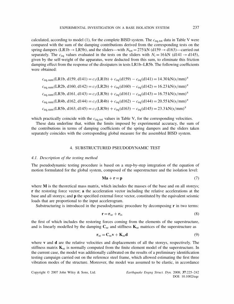
The response spectrum of the Eurocode 8-generated accelerogram assumed as input, characterizedby a peak ground acceleration of 0.3g, is plotted in Figure 12. The experimental response is
Copyright q 2007 John Wiley & Sons, Ltd. Earthquake Engng Struct. Dyn. 2008; 37:225–242DOI: 10.1002/eqe
EXPERIMENTAL INVESTIGATION ON A BASE ISOLATION SYSTEM 239
0 0.5 1 1.5 2 2.5 3 3.5 4 4.5 50
0.1
0.2
0.3
0.4
0.5
0.6
0.7
0.8
Time [s]
Pse
udo-
acce
lera
tion
[g]
Pseudodynamic testInput accelerogram
Figure 12. Response spectrum of the input accelerogram for pseudodynamic test.
-25 -20 -15 -10 -5 0 5 10 15 20 25-40
-30
-20
-10
0
10
20
30
40
Base Displacement [mm]
Bas
e S
hear
[kN
]
ExperimentalNumerical
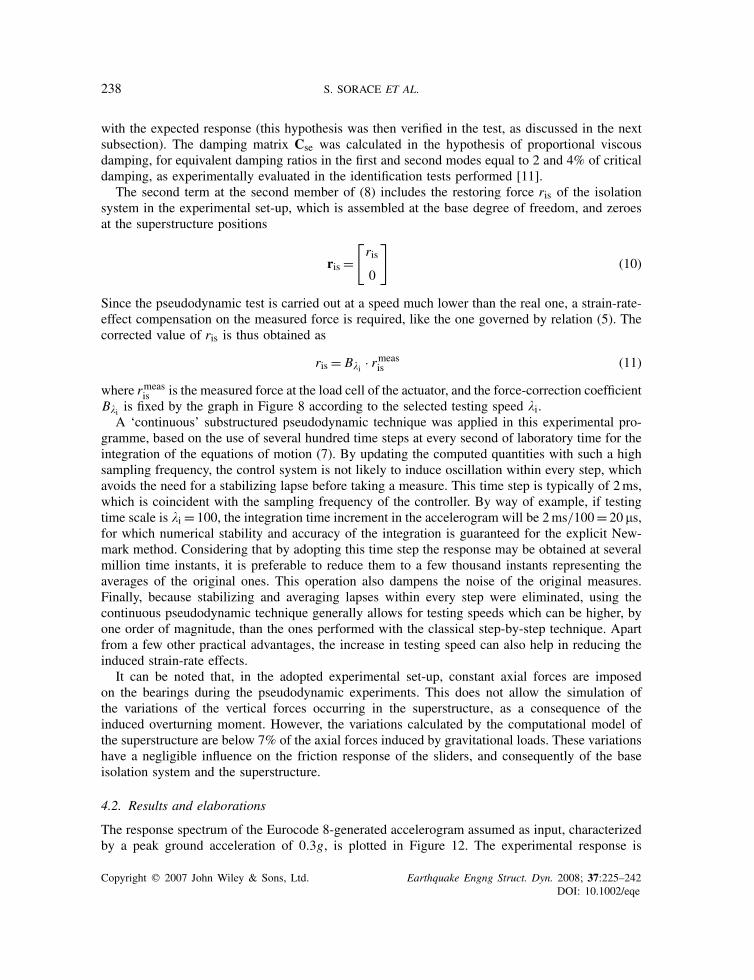
Figure 13. Pseudodynamic test: base shear–base displacement cycles, and relevant numerical simulation.
summed up in Figure 13, where the base shear–base displacement cycles are plotted in superim-position to relevant numerical simulations. The values of the numerical model parameters used inthis analysis were drawn from a best fitting process on the experimental results. In particular, aceq,tot coefficient equal to 13 kN(s/mm)�, and a k2 stiffness of 0.35 kN/mm were identified withthis process. The latter is very close to the stiffness value fixed for the coupled spring dampersin the preliminary design phase (k2t = 0.356 kN/mm) to obtain the target fundamental frequencyfis = 0.704Hz. The experimentally measured frequency was equal to 0.685Hz, which exactlycorresponds to the identified k2 value. Concerning the post-calculated ceq,tot coefficient, this isconsistent with the results of the cyclic tests, as illustrated below. The weight of half-structure con-sidered in the pseudodynamic test is equal to 178.8 kN, i.e. close to the vertical load Ntot = 196 kN
Copyright q 2007 John Wiley & Sons, Ltd. Earthquake Engng Struct. Dyn. 2008; 37:225–242DOI: 10.1002/eqe
240 S. SORACE ET AL.
0 1 2 3 4 5 6 70
500
1000
1500
2000
2500
3000
3500
Time [s]
Ene
rgy
[kN
*mm
]
E i
Ed,v
Ed,f
Figure 14. Pseudodynamic test: energy time histories.
0 1 2 3 4 5 6 7-30
-20
-10
0
10
20
30
Time [s]
Inte
rsto
ry D
rift [
mm
]
Second Story
Original StructureProtected Structure
Figure 15. Second interstorey drift time histories obtained from pseudodynamic tests on the referencesteel structure in fixed-base and base-isolated conditions.
applied in one of the real-time tests on the sliders, for which an equivalent damping coefficientceq = 4.24 kN(s/mm)� was computed. By adding this value to the c2 coefficient in Table III for� = 1, equal to 9.46 kN(s/mm)�, a total equivalent damping coefficient ceq,tot = 13.7 kN(s/mm)�
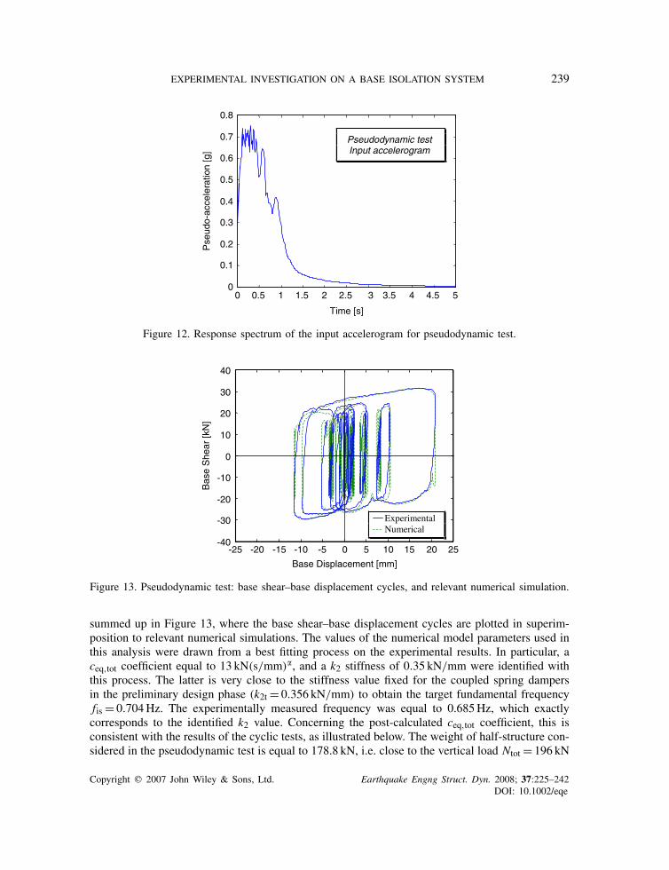
is found, which is close to the above-mentioned value identified from the pseudodynamic test.Figure 14 shows the energy time histories obtained from the pseudodynamic test, Ei being the
input energy, Ed,v the viscous damping energy dissipated by the FV devices, and Ed,f the frictiondamping energy dissipated by the sliding bearings. The energy response highlights 84% fractionof dissipation for FV devices, and 16% fraction for sliders. This provides an indication about thetwo percentile contributions, which are anyway strictly related to the specific characteristics ofany single case study.
Copyright q 2007 John Wiley & Sons, Ltd. Earthquake Engng Struct. Dyn. 2008; 37:225–242DOI: 10.1002/eqe
EXPERIMENTAL INVESTIGATION ON A BASE ISOLATION SYSTEM 241
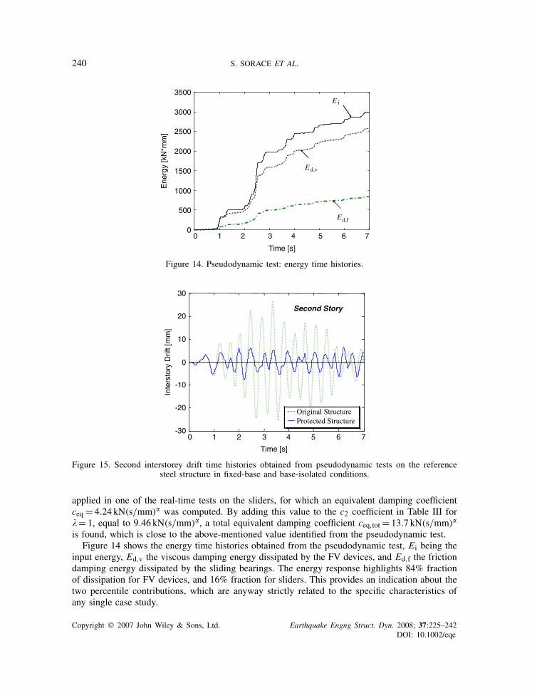
The benefits provided by the BISD system are visually represented in Figure 15, where theinterstorey drift time history of the most stressed storey, namely the second one, is compared withthe corresponding time history obtained from the pseudodynamic test carried out in unprotectedconditions, within the same DISPASS Project [11, 12]. The maximum drift values for the threestoreys, Id1,max, Id2,max and Id3,max, equal to 17.8, 26.3 and 20.7mm (fixed-base conditions),and 4.9, 7.7 and 6.4mm (base-isolated conditions), show 3.63, 3.42, and 3.23 reduction factors,respectively, in passing from the unprotected to the protected frame. This remarkable improvementleads to interstorey drift ratios of 2.5, 3.4, and 3.22 for the first, second, and third storey,respectively, which are largely below the 52 limit corresponding to the highest performance levelpostulated for retrofitted steel frames (‘operational level’), under the basic design earthquake, ininternational performance-based design documents, including FEMA 356 [20]. Optimal control ofbase displacements, constrained within 20.9mm, is also reached, as highlighted by the responsecycles in Figure 13.
5. CONCLUSIONS
The experimental research presented in this paper allowed to reach the objectives formulated inthis new study on the BISD system, as summed up below:
1. Elaboration of test results in terms of energy balance and damping coefficients allowed toverify the linear additive combination of the dissipative action of FV devices when mountedin pairs, as well as of their viscous damping with the frictional damping of steel–Teflonsliding bearings, within a BISD installation.
2. A ‘global’ equivalent damping coefficient was formulated for the system, starting from itsdefinition for FV spring dampers. Moreover, a new calibration of the force correction expres-sion for the strain-rate effects, as included in the ELSA pseudodynamic testing procedure,was developed for the devices experimented in this project. This allowed to successfullyreproduce the responses derived from the corresponding real-time tests.
3. A substantial independence from testing rate was observed for the friction coefficient oflubricated steel–Teflon sliders, as a consequence of their lubrication process carried out incompliance with the most recent standards governing this class of seismic bearings; at thesame time, � was confirmed to be an inverse function of normal stress.
4. Further experimental validation of the analytical and numerical models adopted for the FVspring dampers was obtained, always showing a satisfactory correlation of computed andexperimental data.
5. Enhancement of seismic response provided by the considered protection technology wasassessed by way of a comparison with the results of the pseudodynamic test carried outearlier, with the same input earthquake, on the reference steel structure in fixed-base config-uration. Reduction factors greater than 3 were principally observed in terms of interstoreydrifts, in passing from original to protected conditions. This allowed meeting the remark-ably demanding performance limit assumed as a target for the basic design earthquake afterretrofit.
6. The highly non-linear viscous damping action of FV devices allowed constraining basedisplacements within very low limits, as implicitly imposed by the design equation wherebythe damping coefficient of the spring dampers was preliminarily evaluated.
Copyright q 2007 John Wiley & Sons, Ltd. Earthquake Engng Struct. Dyn. 2008; 37:225–242DOI: 10.1002/eqe
242 S. SORACE ET AL.
ACKNOWLEDGEMENTS
The European Commission financed the research programme DISPASS, a task of which is discussed inthis paper, within contract HPRI-CT-1999-00059. The authors gratefully acknowledge this support.
REFERENCES
1. Skinner RI, Robinson WH, McVerry GH. An Introduction to Seismic Isolation. Wiley: New York, 1993.2. Constantinou MC, Soong TT, Dargush GF. Passive energy dissipation systems for structural design and retrofit.
MCEER Monograph No. 1, Multidisciplinary Center for Earthquake Engineering Research, Buffalo, NY, 1998.3. Soong TT, Dargush GF. Passive Energy Dissipation Systems in Structural Engineering. Wiley: New York, 1997.4. Kelly JM. The role of damping in seismic isolation. Earthquake Engineering and Structural Dynamics 1999;
28:3–20.5. Terenzi G. Dynamics of SDOF systems with nonlinear viscous damping. Journal of Engineering Mechanics
(ASCE) 1999; 125:956–963.6. Sorace S, Terenzi G. Non-linear dynamic modelling and design procedure of FV spring-dampers for base isolation.
Engineering Structures 2001; 23:1556–1567.7. Sorace S, Terenzi G. Non-linear dynamic design procedure of FV spring-dampers for base isolation—frame
building applications. Engineering Structures 2001; 23:1568–1576.8. Sorace S, Terenzi G. Application of a combined base isolation/supplemental damping seismic protection strategy
to a public building in Florence. Proceedings of the International Conference on 250th Anniversary of the 1755Lisbon Earthquake, Lisbon, Portugal. LNEC Publishers: Lisbon, 2005; 481–486.
9. CNR 10018. Apparecchi di appoggio per le costruzioni. Istruzioni per l’impiego [Bearing devices for structures.Instructions for use]. CNR, Bollettino Ufficiale, Rome, Italy, 1999.
10. prEN 1337. Structural bearings. Final Draft, CEN—European Committee for Standardization, Bruxelles, 2003.11. Molina FJ, Sorace S, Terenzi G, Magonette G, Viaccoz B. Seismic tests on reinforced concrete and steel frames
retrofitted with dissipative braces. Earthquake Engineering and Structural Dynamics 2004; 33:1373–1394.12. Sorace S, Terenzi, G, Seismic protection of frame structures by fluid viscous damped braces. Journal of Structural
Engineering (ASCE), September 2006, accepted.13. Schmidt K, Dorka U, Taucer F, Magonette G. Seismic retrofit of a steel frame and a R/C frame with HYDE
systems. Publication EUR 21180 EN, European Commission—Joint Research Centre, IPSC/ELSA, Ispra, Italy,2004.
14. Pekcan G, Mander J, Chen SS. The seismic response of a 1:3 scale model R.C. structure with elastomeric springdampers. Earthquake Spectra 1995; 11:249–267.
15. Lin W-H, Chopra AK. Earthquake response of elastic SDF systems with non-linear fluid viscous dampers.Earthquake Engineering and Structural Dynamics 2002; 31:1623–1642.
16. Jarret SL. Shock-control Technologies, 2007. Available from: http://www.introini.info.17. Dolce M, Cardone D, Croatto F. Frictional behaviour of steel–PTFE interfaces for seismic isolation. Bulletin of
Earthquake Engineering 2005; 3:75–99.18. Mokha A, Constantinou M, Reinhorn A. Teflon bearings in base isolation. I: Testing. Journal of Structural
Engineering (ASCE) 1990; 116:438–454.19. OPCM/3431, Norme tecniche per il progetto, la valutazione e l’adeguamento sismico degli edifici [Technical
Standards for the design, evaluation and seismic retrofit of buildings]. G.U. Rome, Italy, 3 May 2005.20. FEMA 356. Prestandard and Commentary for the Seismic Rehabilitation of Buildings. Building Seismic Safety
Council, Federal Emergency Management Agency, Washington, DC, 2000.21. Naeim F. Design of Seismic Isolated Buildings—From Theory to Practice. Wiley: New York, 1999.
Copyright q 2007 John Wiley & Sons, Ltd. Earthquake Engng Struct. Dyn. 2008; 37:225–242DOI: 10.1002/eqe