Experimental and Theoretical Study of Transient Human Thermal Comfort Response in Convective and...
9
Experimental and theoretical study of the transient rotation of isotropic transparent microparticles in astigmatic optical tweezers Antonio Ambrosio, Bruno Piccirillo, Antonio Sasso, Enrico Santamato * INFM, Dipartimento di Scienze Fisiche dell’Universit a di Napoli ‘‘Federico II’’, via Cintia 80126 Napoli, Italy Received 28 April 2003; received in revised form 20 November 2003; accepted 21 November 2003 Abstract Micrometer-sized rod-like non-birefringent transparent particles trapped by an astigmatic laser beam having el- liptical intensity profile spontaneously rotate until they become aligned with the major axis of the beam cross-section. The observed rotation confirms a simple picture based on orbital angular momentum transfer from the light beam to the trapped particle. A model which regards the particle as a thin cylindrical lens with effective focal lengths f 1 and f 2 has allowed to calculate the applied optical torque and, hence, the time law governing the particle alignment. The time evolution of the particle alignment is studied for different rod-like particles by analysing the sequence of frames re- corded by a CCD camera. The time evolution of the angle a formed between the main axes of the body and the laser shape results in good agreement with the theory for bodies fully immersed in the spot size of the laser. Discrepancies observed for rod-like particles longer than the minor elliptical axis of the beam cross-section, were removed by de- veloping a more general model taking into account the partial overlapping between the body and the laser profile. Ó 2003 Elsevier B.V. All rights reserved. PACS: 42.50.Vk Keywords: Optical tweezers; Orbital angular momentum of light 1. Introduction Manipulation of microscopic objects without mechanical contact with accuracy below the mi- crometric range has been achieved by optical tweezers since years [1]. Optical tweezers exploit optical gradient forces from few tens of fN up to hundreds of pN to produce potential wells where particles are trapped. Optical tweezers have found many applications for the manipulation of bio- logical materials [2] and for the investigation of weak forces on microscopic scale [3–5]. There are many experimental situations, how- ever, where individual biological particles have to * Corresponding author. Tel.: +39-081-676359; fax: +39-081- 676346. E-mail address: [email protected] (E. Santam- ato). 0030-4018/$ - see front matter Ó 2003 Elsevier B.V. All rights reserved. doi:10.1016/j.optcom.2003.11.057 Optics Communications 230 (2004) 337–345 www.elsevier.com/locate/optcom
-
Upload
independent -
Category
Documents
-
view
0 -
download
0
Transcript of Experimental and Theoretical Study of Transient Human Thermal Comfort Response in Convective and...

Optics Communications 230 (2004) 337–345
www.elsevier.com/locate/optcom
Experimental and theoretical study of the transient rotationof isotropic transparent microparticles in astigmatic
optical tweezers
Antonio Ambrosio, Bruno Piccirillo, Antonio Sasso, Enrico Santamato *
INFM, Dipartimento di Scienze Fisiche dell’Universit�aa di Napoli ‘‘Federico II’’, via Cintia 80126 Napoli, Italy
Received 28 April 2003; received in revised form 20 November 2003; accepted 21 November 2003
Abstract
Micrometer-sized rod-like non-birefringent transparent particles trapped by an astigmatic laser beam having el-
liptical intensity profile spontaneously rotate until they become aligned with the major axis of the beam cross-section.
The observed rotation confirms a simple picture based on orbital angular momentum transfer from the light beam to
the trapped particle. A model which regards the particle as a thin cylindrical lens with effective focal lengths f1 and f2has allowed to calculate the applied optical torque and, hence, the time law governing the particle alignment. The time
evolution of the particle alignment is studied for different rod-like particles by analysing the sequence of frames re-
corded by a CCD camera. The time evolution of the angle a formed between the main axes of the body and the laser
shape results in good agreement with the theory for bodies fully immersed in the spot size of the laser. Discrepancies
observed for rod-like particles longer than the minor elliptical axis of the beam cross-section, were removed by de-
veloping a more general model taking into account the partial overlapping between the body and the laser profile.
� 2003 Elsevier B.V. All rights reserved.
PACS: 42.50.Vk
Keywords: Optical tweezers; Orbital angular momentum of light
1. Introduction
Manipulation of microscopic objects without
mechanical contact with accuracy below the mi-
* Corresponding author. Tel.: +39-081-676359; fax: +39-081-
676346.
E-mail address: [email protected] (E. Santam-
ato).
0030-4018/$ - see front matter � 2003 Elsevier B.V. All rights reserv
doi:10.1016/j.optcom.2003.11.057
crometric range has been achieved by optical
tweezers since years [1]. Optical tweezers exploit
optical gradient forces from few tens of fN up to
hundreds of pN to produce potential wells whereparticles are trapped. Optical tweezers have found
many applications for the manipulation of bio-
logical materials [2] and for the investigation of
weak forces on microscopic scale [3–5].
There are many experimental situations, how-
ever, where individual biological particles have to
ed.
338 A. Ambrosio et al. / Optics Communications 230 (2004) 337–345
be oriented or where measuring or inducing me-
chanical torques it is important. Recently, Sacconi
et al. [6] have combined optical tweezers and a
magnetic trap to rotate super-paramagnetic beads.
However, when non-magnetic biological objects
are envisaged, they have to be attached to themagnetic beads, which is a difficult task. It seems
therefore interesting developing all-optical systems
able to simultaneously trap and rotate the particles
under investigation. In this case optical tweezers
are used as a tool to transfer angular momentum
from light to the trapped particles. As it is well
known the angular momentum carried by light can
be distinguished by the spin angular momentumassociated to the circular polarization and the or-
bital angular momentum associated with the spa-
tial distribution of the wavefront [7]. For circularly
polarized light the photon spin is well known to be
��h for r�, respectively. It has been demonstrated
[8] that helical wave fronts with azimuthal phase
term expðil/Þ give rise to an orbital angular mo-
mentum for linearly polarized light of l�h perphoton. As it is well known the rotation of mac-
roscopic bodies by angular momentum of light
was demonstrated for the first time on 1936 by
Beth [9] in an elegant and famous experiment.
Direct angular momentum transfer can be
achieved in two ways: (a) by photon absorption
and (b) by photon scattering. In the former case,
photons are absorbed along with their own angu-lar momentum. In the latter case, to the body is
transferred only the difference in the angular mo-
mentum between the incident and scattered pho-
tons. This last process was first observed in liquid
crystals by Santamato et al. [10] which named such
a phenomena as self-induced stimulated light
scattering (SISLS). The SISLS was later used to
realize liquid-crystal-based molecular motors [11].In recent times, spin angular momentum was
transferred to rotate birefringent [12,13] particles
trapped by optical tweezers. In another experiment
Friese et al. [14] have demonstrated that absorbing
particles trapped in a Gaussian beam were set into
rotation by elliptically polarized light and rotate in
a direction that depends on the handledness of the
ellipticity. Very recently, the optical rotation ofelongated rods made of transparent isotropic ma-
terial was achieved using the light polarization,
because of the so-called ‘‘form birefringence’’ of
the trapped particles [15]. In these works involving
optical tweezers only the spin of photons was ex-
ploited. New class of experiments where the orbital
angular momentum is transferred was first realized
by Sato et al. [16] which rotated red blood cellsdragging them with a laser beam prepared in a
higher-order Hermite–Gauss mode. In that ex-
periment a rectangular aperture was placed inside
the laser cavity to force the laser to oscillate in
TEM�01. Blood cells were aligned along the major
axis of the pattern mode and were oriented in the
transverse plane by rotating the rectangular aper-
ture. In a more recent paper O�Neil and Padgett[17] revisited Sato�s idea with a simplified method
by putting a rectangular aperture simply along the
path of a Gaussian laser beam. They showed that
an asymmetric object trapped in the beam waist
was aligned along the aperture axis. One alterna-
tive approach to achieve rotation was very recently
performed by our group [18] by means of an
astigmatic laser beam created by a cylindricallens.
Direct observation of transfer of angular mo-
mentum to absorptive particles from a laser beam
with a phase singularity (LG03 doughnut mode
obtained by computer generated hologram) was
demonstrated by Friese and coworkers [19,20].
Simultaneous transfer of spin and angular mo-
mentum has also been studied by Simpson et al.[21] in absorbing particles.
Several schemes have been recently proposed
where objects were rotated in the plane perpen-
dicular to the direction of the trapping beam,
thus adding a new useful degree of control.
Some of them are based on the peculiar shape of
either the trapped objects [22,23] or the trapping
optical field pattern. For example, Paterson et al.[24,25] drove the trapped particles around a
circle by rotating the intensity pattern created by
interference of a laser beam prepared in a La-
guerre–Gauss mode with a second Gaussian laser
beam. Optical torque created by induced polar-
ization in dielectric material by linearly polarized
laser beam has been demonstrated to be able to
manipulate and control the rotation of micro-objects [26,27]. In a very recent paper, Bingelyte
et al. [28] demonstrated that microscopic objects
A. Ambrosio et al. / Optics Communications 230 (2004) 337–345 339
held simultaneously in a double-optical tweezers
could be set into controlled rotation about any
axis of choice.
All the experiments where light angular mo-
mentum is transferred to trapped particles belong
to two main fields of applications: either to inducepermanent rotation like a micro-motor [29], or just
for alignment. Of course, especially for biological
applications which need to rotate particles or to
exert on macromolecules torques with a high de-
gree of control the latter case is much more useful.
While quantitative measurements of rotation fre-
quency of particles in an optical spanner have been
reported in several papers [13,20,21], according toour knowledge, no studies have been performed
regarding the time law of microparticles motion
during their alignment along the optical trap.
In the present work, we studied in details the
angular time law obeyed by the motion of elon-
gated trapped particles under the action of an as-
tigmatic laser trap. In particular, we focused on
the effects due to the shape of the particle and toits overlapping with the incident light intensity
profile.
2. Theory
The calculation of the orbital angular momen-
tum transferred from an elliptical laser beam whenpassing through a cylindrical lens has been already
discussed with great details in [30,31]. In the present
work the optical torque transferred to the lens was
calculated with a simplified theoretical description
with respect to that reported in [18]. When passing
through a transparent body each photon is scattered
from a state with orbital angular momentum �hr� k
to a state with orbital angular momentum �hr� k0,where k and k0 are the incident and scattered photon
wavevectors, respectively. The body receives an
amount l ¼ �hr� ðk0 � kÞof angularmomentumper
photon. The overall torqueM acting on the body is
given by M ¼Rl/ðx; yÞdxdy, where /ðx; yÞ is the
photon flux in the xy-plane transverse to the beam.
The light intensity Iðx; yÞ is related to the photon
flux by Iðx; yÞ ¼ hm/ðx; yÞ, m being the optical fre-quency. In the paraxial approximation, the optical
wavevector is related to the optical phase w by
k ¼ rw. We may therefore write down M as
M ¼ P2pm
hr�rðw0 � wÞi; ð1Þ
where P is the incident optical power and h�imeans
the intensity-weighted average over the spatial
beam profile. The difference w0 � w is the phasechange that the optical wave suffers in traversing
the body, that we suppose perfectly transparent.
For a body of refractive index n immersed in a
fluid of refractive index n0, we have
w0 � w ¼ ð2p=kÞðn� n0Þdðx; yÞ; ð2Þ
where dðx; yÞ is the local thickness of the body and
k ¼ c=m is the optical wavelength in vacuum. For
the sake of simplicity, we assume the intensity
profile of the laser beam in the trapping region
Gaussian with different radii wx and wy (1=e2 in-tensity) along the x and y directions, respectively.
The body is regarded as a thin cylindrical lens with
effective focal lengths f1 and f2 and oriented at
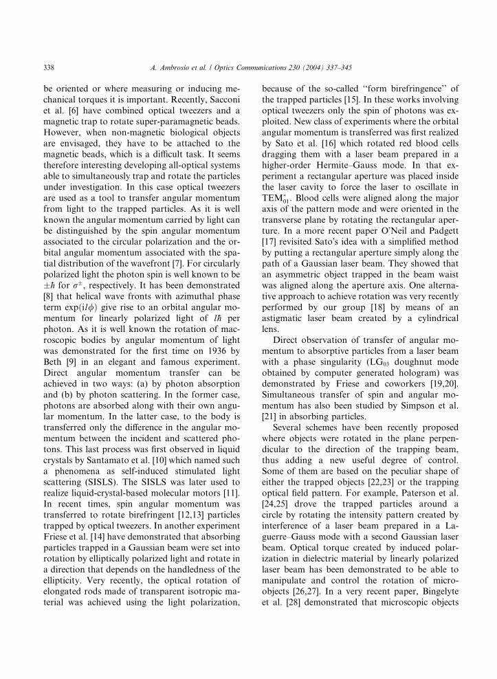
angle a with respect to the x-axis (see Fig. 1).
Without loss of generality, we assume the major
axis of the intensity profile directed along x (i.e.,
wx > wy). Under these assumptions, the phase
change in Eq. (2) becomes
w0 � w ¼ � pkf1
ðx cos aþ y sin aÞ2
� pkf2
ðx sin a� y cos aÞ2: ð3Þ
Taking the z-component of Eq. (1), we obtain
Mz ¼ �P ðf1 � f2Þðw2
x � w2yÞ
4cf1f2sin 2a
¼ �A sin 2a: ð4Þ
Here Mz is the z-component of the orbital an-
gular momentum that the trapped body extracts
from the light beam per unit time and, hence, itprovides the mechanical torque acting on the
body. Eq. (4) shows that in the case of spherical
particles (f1 ¼ f2) or circularly-shaped beams
(wx ¼ wy) the torque Mz is zero. Moreover, Mz
vanishes when a ¼ 0 or a ¼ p=2. Under the torque
Mz the body starts rotating around the z-axis untilit reaches its stable equilibrium position a ¼ 0
Fig. 1. The trapped particle can be considered as a cylindrical lens acting on the beam. Beam refraction results in a couple of forces on
the lens.
340 A. Ambrosio et al. / Optics Communications 230 (2004) 337–345
when A > 0, or a ¼ p=2 when A < 0. In the case of
overdamped rotator, the equation of motion for
the body is
�c _aa ¼ A sin 2a; ð5Þwhere c is the viscosity coefficient involved in the
rotation. For a cylinder of length L and diameter
d, c is given by [32]
c ¼ pgL3
3½ln p � dðpÞ� ; ð6Þ
where g is the viscosity of the surrounding fluid,
p ¼ L=d and dðpÞ is a tabulated function ac-
counting for end-effects [32]. Eq. (5) can be solved
yielding, for A > 0,
tan aðtÞ ¼ e�t=s tan að0Þ; ð7Þwith time constant s ¼ c=2A.
3. The experimental apparatus
We realized optical tweezers to trap and orient
micro-particles immersed in distilled water. A
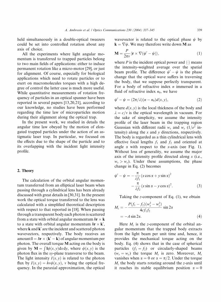
block scheme of our apparatus is shown in Fig. 2.
In our previous paper [18] we used a TEM00
doubled-Nd:YVO4 laser (k ¼ 532 nm, impinging
power 100–300 mW) whose intensity profile was
made elliptical by using a cylindrical lens. In the
present work instead as laser source we used a
semiconductor diode laser emitting in the nearinfrared (k ¼ 785 nm, impinging power ranging
from 10 to 30 mW). The beam profile of the beam
emerging from the diode laser exhibited an ellip-
tical shape with radii Wx ¼ 3 mm and Wy ¼ 1 mm
at 1=e2 intensity. The beam was collimated
through a laser diode objective with focal length
8.5 mm. The intensity profile of the trapping beam
in the focal region of the microscope was mademore elliptical by using the cylindrical lens L1, with
focal length fy ¼ 80 mm and cylindrical axis along
the x direction. The focal plane of the lens L1 was
set at the standard distance of 160 mm from the
objective plane of the microscope. A polarizing
cube beam-splitter was inserted between the eye-
piece and the microscope objective so to observe
the particles through the same optical port whichthe laser beam was injected into. The focusing lens
L1 assured proper filling of the back pupil of the
objective to achieve high trapping efficiency. The
trap used a 40� (NA¼ 0.65 in water) and a 100�(NA¼ 1.25 in water) microscope objectives. The
beam radii (1=e2 intensity) at the trapping position
were wx ¼ 44� 2 lm, and wy ¼ 2:8� 0:1 lm with
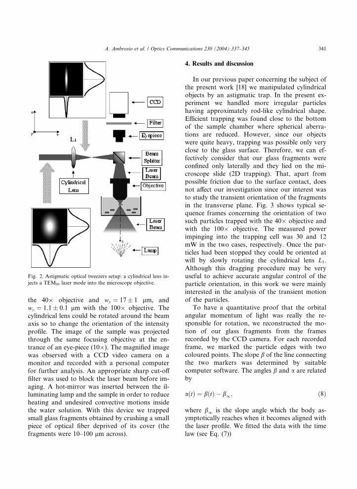
Fig. 2. Astigmatic optical tweezers setup: a cylindrical lens in-
jects a TEM00 laser mode into the microscope objective.
A. Ambrosio et al. / Optics Communications 230 (2004) 337–345 341
the 40� objective and wx ¼ 17� 1 lm, and
wy ¼ 1:1� 0:1 lm with the 100� objective. The
cylindrical lens could be rotated around the beam
axis so to change the orientation of the intensity
profile. The image of the sample was projected
through the same focusing objective at the en-
trance of an eye-piece (10�). The magnified image
was observed with a CCD video camera on amonitor and recorded with a personal computer
for further analysis. An appropriate sharp cut-off
filter was used to block the laser beam before im-
aging. A hot-mirror was inserted between the il-
luminating lamp and the sample in order to reduce
heating and undesired convective motions inside
the water solution. With this device we trapped
small glass fragments obtained by crushing a smallpiece of optical fiber deprived of its cover (the
fragments were 10–100 lm across).
4. Results and discussion
In our previous paper concerning the subject of
the present work [18] we manipulated cylindrical
objects by an astigmatic trap. In the present ex-periment we handled more irregular particles
having approximately rod-like cylindrical shape.
Efficient trapping was found close to the bottom
of the sample chamber where spherical aberra-
tions are reduced. However, since our objects
were quite heavy, trapping was possible only very
close to the glass surface. Therefore, we can ef-
fectively consider that our glass fragments wereconfined only laterally and they lied on the mi-
croscope slide (2D trapping). That, apart from
possible friction due to the surface contact, does
not affect our investigation since our interest was
to study the transient orientation of the fragments
in the transverse plane. Fig. 3 shows typical se-
quence frames concerning the orientation of two
such particles trapped with the 40� objective andwith the 100� objective. The measured power
impinging into the trapping cell was 30 and 12
mW in the two cases, respectively. Once the par-
ticles had been stopped they could be oriented at
will by slowly rotating the cylindrical lens L1.
Although this dragging procedure may be very
useful to achieve accurate angular control of the
particle orientation, in this work we were mainlyinterested in the analysis of the transient motion
of the particles.
To have a quantitative proof that the orbital
angular momentum of light was really the re-
sponsible for rotation, we reconstructed the mo-
tion of our glass fragments from the frames
recorded by the CCD camera. For each recorded
frame, we marked the particle edges with twocoloured points. The slope b of the line connecting
the two markers was determined by suitable
computer software. The angles b and a are related
by
aðtÞ ¼ bðtÞ � b1; ð8Þ
where b1 is the slope angle which the body as-ymptotically reaches when it becomes aligned with
the laser profile. We fitted the data with the time
law (see Eq. (7))
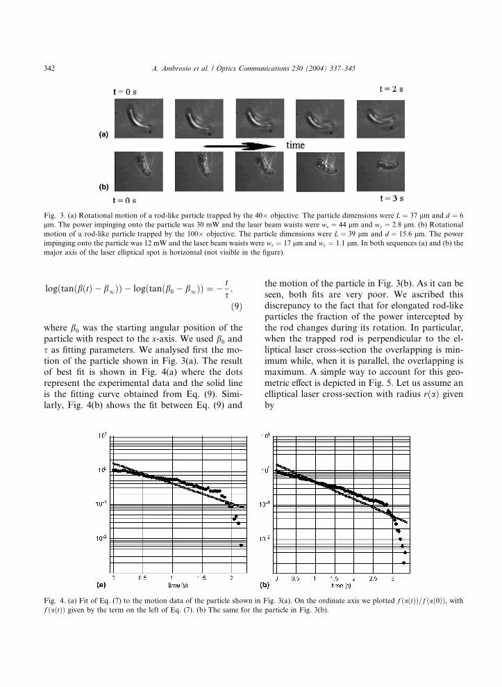
Fig. 3. (a) Rotational motion of a rod-like particle trapped by the 40� objective. The particle dimensions were L ¼ 37 lm and d ¼ 6
lm. The power impinging onto the particle was 30 mW and the laser beam waists were wx ¼ 44 lm and wy ¼ 2:8 lm. (b) Rotational
motion of a rod-like particle trapped by the 100� objective. The particle dimensions were L ¼ 39 lm and d ¼ 15:6 lm. The power
impinging onto the particle was 12 mW and the laser beam waists were wx ¼ 17 lm and wy ¼ 1:1 lm. In both sequences (a) and (b) the
major axis of the laser elliptical spot is horizontal (not visible in the figure).
342 A. Ambrosio et al. / Optics Communications 230 (2004) 337–345
logðtanðbðtÞ � b1ÞÞ � logðtanðb0 � b1ÞÞ ¼ � ts;
ð9Þ
where b0 was the starting angular position of the
particle with respect to the x-axis. We used b0 and
s as fitting parameters. We analysed first the mo-
tion of the particle shown in Fig. 3(a). The result
of best fit is shown in Fig. 4(a) where the dots
represent the experimental data and the solid line
is the fitting curve obtained from Eq. (9). Simi-larly, Fig. 4(b) shows the fit between Eq. (9) and
Fig. 4. (a) Fit of Eq. (7) to the motion data of the particle shown in
f ðaðtÞÞ given by the term on the left of Eq. (7). (b) The same for the
the motion of the particle in Fig. 3(b). As it can be
seen, both fits are very poor. We ascribed this
discrepancy to the fact that for elongated rod-like
particles the fraction of the power intercepted by
the rod changes during its rotation. In particular,when the trapped rod is perpendicular to the el-
liptical laser cross-section the overlapping is min-
imum while, when it is parallel, the overlapping is
maximum. A simple way to account for this geo-
metric effect is depicted in Fig. 5. Let us assume an
elliptical laser cross-section with radius rðaÞ givenby
Fig. 3(a). On the ordinate axis we plotted f ðaðtÞÞ=f ðað0ÞÞ, withparticle in Fig. 3(b).
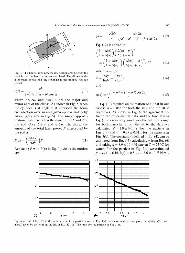
Fig. 5. This figure shows how the intersection area between the
particle and the laser beam was calculated. The ellipses is the
laser beam profile and the rectangle is the trapped rod-like
particle.
A. Ambrosio et al. / Optics Communications 230 (2004) 337–345 343
rðaÞ ¼ ab
2ffiffiffiffiffiffiffiffiffiffiffiffiffiffiffiffiffiffiffiffiffiffiffiffiffiffiffiffiffiffiffiffiffiffiffiffiffiffiffia2 sin2 aþ b2 cos2 a
p ; ð10Þ
where a � 2wx and b � 2wy are the major and
minor axes of the ellipse. As shown in Fig. 5, when
the cylinder is at angle a, it intersects the beam
cross-section over an area given approximately by2drðaÞ (gray area in Fig. 5). This simple approxi-
mation holds true when the dimensions L and d of
the rod obey LP a and d 6 b. Therefore, the
amount of the total laser power P intercepted by
the rod is
P ðaÞ ¼ 8drðaÞpab
� �P : ð11Þ
Replacing P with P ðaÞ in Eq. (4) yields the motion
law
Fig. 6. (a) Fit of Eq. (13) to the motion data of the particle shown in
gðaðtÞÞ given by the term on the left of Eq. (13). (b) The same for th
c _aa ¼ � 4ffiffiffi2
pdA
psin 2affiffiffiffiffiffiffiffiffiffiffiffiffiffiffiffiffiffiffiffiffiffiffiffiffiffiffiffiffiffiffiffiffiffiffiffiffiffiffiffiffiffiffiffiffiffiffiffiffiffiffi
a2 þ b2 � ða2 � b2Þ cos 2ap : ð12Þ
Eq. (12) is solved to
1þ DðaÞ1� DðaÞ
� �DðaÞ � mDðaÞ þ m
� �m
¼ 1þ Dða0Þ1� Dða0Þ
� �Dða0Þ � mDða0Þ þ m
� �m
e�t=s0 ; ð13Þ
where m ¼ b=a,
s0 ¼ pac16dA
¼ pa8d
� �s ð14Þ
and
DðaÞ ¼ffiffiffiffiffiffiffiffiffiffiffiffiffiffiffiffiffiffiffiffiffiffiffiffiffiffiffiffiffiffiffiffiffiffiffiffiffiffiffiffiffiffiffiffiffiffiffiffiffiffi1þ m2 � ð1� m2Þ cos 2a
2
r: ð15Þ
Eq. (13) requires an estimation of m that in our
case is m ¼ 0:065 for both the 40� and the 100�objectives. As shown in Fig. 6, the agreement be-
tween the experimental data and the time law in
Eq. (13) is now very good over the full time range
for both particles. From the fit to the data we
calculated s0 ¼ 1:9� 0:01 s for the particle inFig. 3(a) and s0 ¼ 0:87� 0:01 s for the particle in
Fig. 3(b). The constant A, defined in Eq. (4), can be
estimated from Eq. (13) calculating c from Eq. (6)
and taking g ¼ 8:9� 10�3 N s/m2 at T ¼ 25 �C for
water. For the particle in Fig. 3(a) we estimated
p ¼ L=d ¼ 6:16, dðpÞ ¼ 0:51, c ¼ 3:6� 10�16 Nm s,
Fig. 3(a). On the ordinate axis we plotted gðaðtÞÞ=gðað0ÞÞ, withe particle in Fig. 3(b).
344 A. Ambrosio et al. / Optics Communications 230 (2004) 337–345
A ¼ 5:5� 10�16 Nm.For the particle in Fig. 3(b) we
estimated p ¼ L=d ¼ 2:5, dðpÞ ¼ 0:30, c ¼ 9:0�10�16 Nm s,A ¼ 4:6� 10�16 Nm.From the value of
A we also estimated the order of magnitude of the
torque involved during the rotation as Mz � 4ffiffiffi2
pdA=ðp
ffiffiffiffiffiffiffiffiffiffiffiffiffiffiffia2 þ b2
pÞ � 6:7� 10�17 N m, corres-
ponding to an optical force acting on the rotating
rod F � Mz=L � 1:8 pN for the particle in Fig. 3(a).
Similarly, for the particle in Fig. 3(b), we found
Mz � 3:7� 10�17 Nmand F � 9:3 pN. These forces
are of the right order of magnitude of the forces
usually involved in optical tweezers.
5. Conclusions
We presented a study on the transfer of the
orbital angular momentum of light to transparent
isotropic bodies trapped in optical tweezers with
laser beam having an elliptical profile. We studied,
in the transient regime, the laser-induced orienta-
tion process of particles having elongated rod-likeshapes and different sizes. A simple time law based
on angular momentum conservation was found in
poor agreement with the observed motion. We
ascribed this discrepancy to the fact that a time
varying fraction of the laser power is intercepted
by the particle during its rotation. A corrected
motion law accounting for this geometric effect
was proposed and found in excellent agreementwith our experimental findings. Having a proper
time law for particle rotation may be very useful
when dynamic rather than static torque measure-
ments are envisaged. Dynamic torque measure-
ments, in fact, do not require anchoring the
particle to a fixed body (e.g., the sample walls or
glass beads [6,33]). Fixing the particle, in fact, may
be a difficult task, especially in biological appli-cations. The dynamic technique presented here,
moreover, does not require the exotic laser sources
commonly used to transfer the orbital angular
momentum of light as, for example, Laguerre–
Gauss beams.
Acknowledgements
We thank INFM (Istituto Nazionale per la Fi-
sica della Materia) and MIUR (Ministero
dell�Istruzione, Universit�aa e Ricerca) for financial
support.
References
[1] A. Ashkin, J.M. Dziedzic, J.E. Bjorkholm, S. Chu, Opt.
Lett. 11 (1986) 288.
[2] A. Ashkin, IEEE J. Sel. Top. Quant. Electron. 6 (2000)
841.
[3] K.O. Greulich, Micromanipulation by Light in Biology
and Medicine, Birkhausar, Basel, 1999.
[4] C. Bustamante, Z. Bryant, S.B. Smith, Nature 421 (2003)
423.
[5] A.D. Metha, M. Rief, J.A. Spudich, D.A. Smith, R.M.
Simmons, Science 283 (1999) 1689.
[6] L. Sacconi, G. Romano, R. Ballerini, M. Capitano, M.D.
Pas, M. Giunti, D. Dunlap, L. Finzi, F.S. Pavone, Opt.
Lett. 26 (2001) 1359.
[7] L. Allen et al., Progr. Opt. XXXIX (1999) 291.
[8] L. Allen, M.W. Beijersbergen, R.J. Spreeuw, J.P. Woerd-
man, Phys. Rev. A 22 (1992) 8185.
[9] R.A. Beth, Phys. Rev. 50 (1936) 115.
[10] E. Santamato, M. Romagnoli, M. Settembre, B. Daino,
Y.R. Shen, Phys. Rev. Lett. 61 (1988) 113.
[11] T.V. Galstyan, V. Drnoyan, Phys. Rev. Lett. 78 (1997)
2760.
[12] D.N. Moothoo, J. Arlt, R.S. Conroy, F. Akerboom, A.
Voit, K. Dholakia, Am. J. Phys. 69 (2001) 271.
[13] M.E.J. Friese, T.A. Nieminen, N.R. Heckenberg, H.
Rubinsztein-Dunlop, Nature 394 (1998) 348.
[14] M.E.J. Friese, T.A. Nieminen, N.R. Heckenberg, H.
Rubinsztein-Dunlop, Opt. Lett. 23 (1998) 1.
[15] A.I. Bishop, T.A. Nieminen, N.R. Heckenberg, H. Rubin-
stein-Dunlop, Phys. Rev. A 68 (2003) 033802.
[16] S. Sato, M. Ishigure, H. Inaba, Electron. Lett. 27 (1991)
1831.
[17] A.T. O�Neil, M.J. Padgett, Opt. Lett. 27 (2002) 743.
[18] E. Santamato, A. Sasso, B. Piccirillo, A. Vella, Opt.
Express 10 (2002) 871.
[19] H. He, M.E.J. Friese, N.R. Heckenberg, H. Rubinsztein-
Dunlop, Phys. Rev. Lett. 75 (1995) 826.
[20] M.E.J. Friese, J. Enger, H. Rubinsztein-Dunlop, N.R.
Heckenberg, Phys. Rev. A 54 (1996) 1593.
[21] N.B. Simpson, K. Dholakia, L. Allen, M.J. Padgett, Opt.
Lett. 22 (1997) 1593.
[22] P. Galajda, P. Ormos, Appl. Phys. Lett. 78 (2001) 249.
[23] P. Galajda, P. Ormos, Opt. Express (2003) 446.
[24] L. Paterson, M.P. MacDonald, J. Arlt, W. Sibbett, P.E.
Bryant, K. Dholakia, Science 292 (2001) 912.
[25] M.P. MacDonald, K. Volke-Sepulveda, L. Paterson, J.
Arlt, W. Sibbet, K. Dholakia, Opt. Commun. 201 (2002)
21.
[26] K.D. Bonin, B. Kourmanov, Opt. Express 10 (2002) 984.
[27] E. Higurashi, R. Sawada, T. Ito, Phys. Rev. E 59 (1999)
3676.

A. Ambrosio et al. / Optics Communications 230 (2004) 337–345 345
[28] V. Bingelyte, J. Leach, J. Courtial, M.J. Padgett, Appl.
Phys. Lett. 82 (2003) 829.
[29] Zong-Ping Luo, Yu-Long Sun, Kai-Nan An, Appl. Phys.
Lett. 76 (2002) 1779.
[30] J. Courtial, K. Dholakia, L. Allen, M.J. Padgett, Opt.
Commun. 144 (1997) 210.
[31] M.W. Beijersbergen, L. Allen, H.E.L.O. van der Veen, J.P.
Woerdmann, Opt. Commun. 96 (1993) 123.
[32] M.M. Tirado, J.G. de la torre, J. Chem. Phys. 73 (1980)
1986.
[33] Y. Tsuda, H. Yasutake, A. Ishijima, T. Yamagida, Proc.
Natl. Acad. Sci. USA 93 (1996) 12937.