Comfort Co. Catalogue – Canada - Permobil CA
44
-
Upload
khangminh22 -
Category
Documents
-
view
2 -
download
0
Transcript of Comfort Co. Catalogue – Canada - Permobil CA

1
ABOUT USComfort Company manufactures seating
and postural support systems designed for
people with a wide range of rehabilitation
needs. We are committed to providing our
customers with quality products designed
for comfort, durability, and ease of use
for paediatric, geriatric, or bariatric users.
Our vision is to lead in the development,
manufacturing, and delivery of the most
innovative seating & postural solutions
which provide the highest level of comfort,
functionality, and quality of life.
MANUFACTURING
New Berlin, WI
(262) 432-0830
CANADIAN CONTACTS P: 800.265.9830
F: 877.636.8944
www.permobil.ca
BACK SUPPORT ACCESSORIES
BODILINK™ HEAD SUPPORT PADS & HARDWARE 15 - 16
LATERAL TRUNK SUPPORTS & HARDWARE 17 - 18
BACK SUPPORT SYSTEMS
ACTA-BACK ® 7 - 8
ACTA-BACK ® DEEP 9
ACTA-BACK ® CONTOUR 10
ACTA-RELIEF™ 1 1 - 12
ACTA-EMBRACE™ 13 - 14
Products may be covered by one or more patents or pending patent applications. See www.comfortcompany.com/ip
SEATING SURFACES
SEATING SURFACE S IZE GUIDE 22
ACTA-EMBRACE™ ATI 23 - 24
M2 ATI 25 - 26
ACTA-EMBRACE™ 27
M2 28
CURVE ® 29
SEATING SURFACE ACCESSORIES
LATERAL THIGH SUPPORTS 30
RIGID INSERT 30
REMOVABLE SOLID SEAT PAN 30
REPLACEMENT COVERS 31
INCONTINENT PROOF L INER 31
ACCESSORIES
COMFORT FOOT S INGLE 33
COMFORT FOOT DOUBLE 34
FLEXION FOOTBOX™ 35
CALF PROTECTOR 35
QUICK RELEASE AMP 36
SWING-AWAY AMP 37
COMFORT ARM ® 38 - 39
1
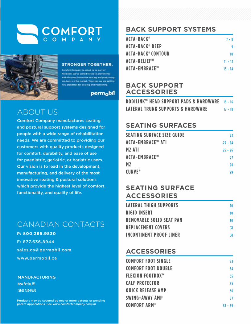
Stretch-Air™ is designed to be airy and breathable with superior stretch. Latex-free Stretch-Air™ provides heat dissipation for comfort while the multi-directional stretch contributes to pressure relief by allowing the user to gain the full benefits of the back support or cushion design.
Comfort-Tek™ is smooth and strong yet extremely soft for amazing comfort. The multidirectional stretch provides pressure relief by allowing the fabric to better conform to the individual’s unique shape. Designed for infection control and as an incontinence barrier, latex-free Comfort-Tek™ is easily cleaned with common disinfectants.
STRETCH-AIR™
REFLECTIVE PIPING GLIDEWEAR®
COMFORT-TEK™
Comfort Company back supports and cushions feature reflective piping to ensure we are doing our part to promote safety and protect the wheelchair user. Reflective piping has the ability to return a large portion of light directly back to the source it came from, allowing it to be seen from up to 500 feet away in low light conditions.
Patent Pending
The GlideWear® shear reduction panel is specifically designed to reduce the risk of Decubitus Ulcer formation and also promotes the healing process of existing problem
areas. GlideWear® is lightweight, breathable and reduces
moisture buildup for micro-climate control. This allows
GlideWear® to help maintain skin integrity as well as
promote the healing of existing wounds.
U.S. GlideWear® Patent No. 8,646,459
COVER TECHNOLOGY
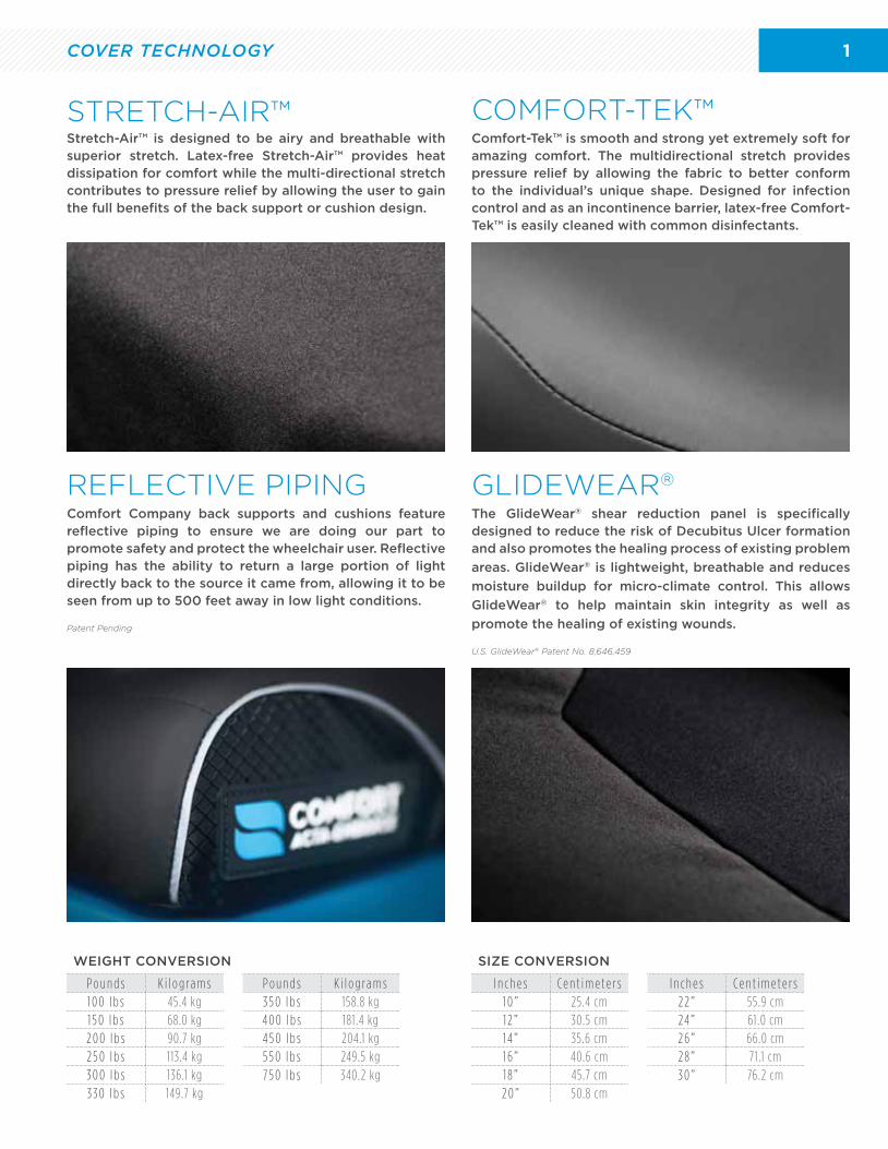
WEIGHT CONVERSION
P o u n d s K i l o g ra m s P o u n d s K i l o g ra m s1 0 0 l b s 45.4 kg 3 5 0 l b s 158.8 kg1 5 0 l b s 68.0 kg 4 0 0 l b s 181 .4 kg2 0 0 l b s 90.7 kg 4 5 0 l b s 204.1 kg2 5 0 l b s 113.4 kg 5 5 0 l b s 249.5 kg3 0 0 l b s 136.1 kg 7 5 0 l b s 340.2 kg3 3 0 l b s 149.7 kg
SIZE CONVERSION
I n c h e s C e n t i m e t e r s I n c h e s C e n t i m e t e r s1 0 ” 25.4 cm 2 2 ” 55.9 cm1 2 ” 30.5 cm 24 ” 61 .0 cm1 4 ” 35.6 cm 2 6 ” 66.0 cm1 6 ” 40.6 cm 2 8 ” 71 .1 cm1 8 ” 45.7 cm 3 0 ” 76.2 cm2 0 ” 50.8 cm
22
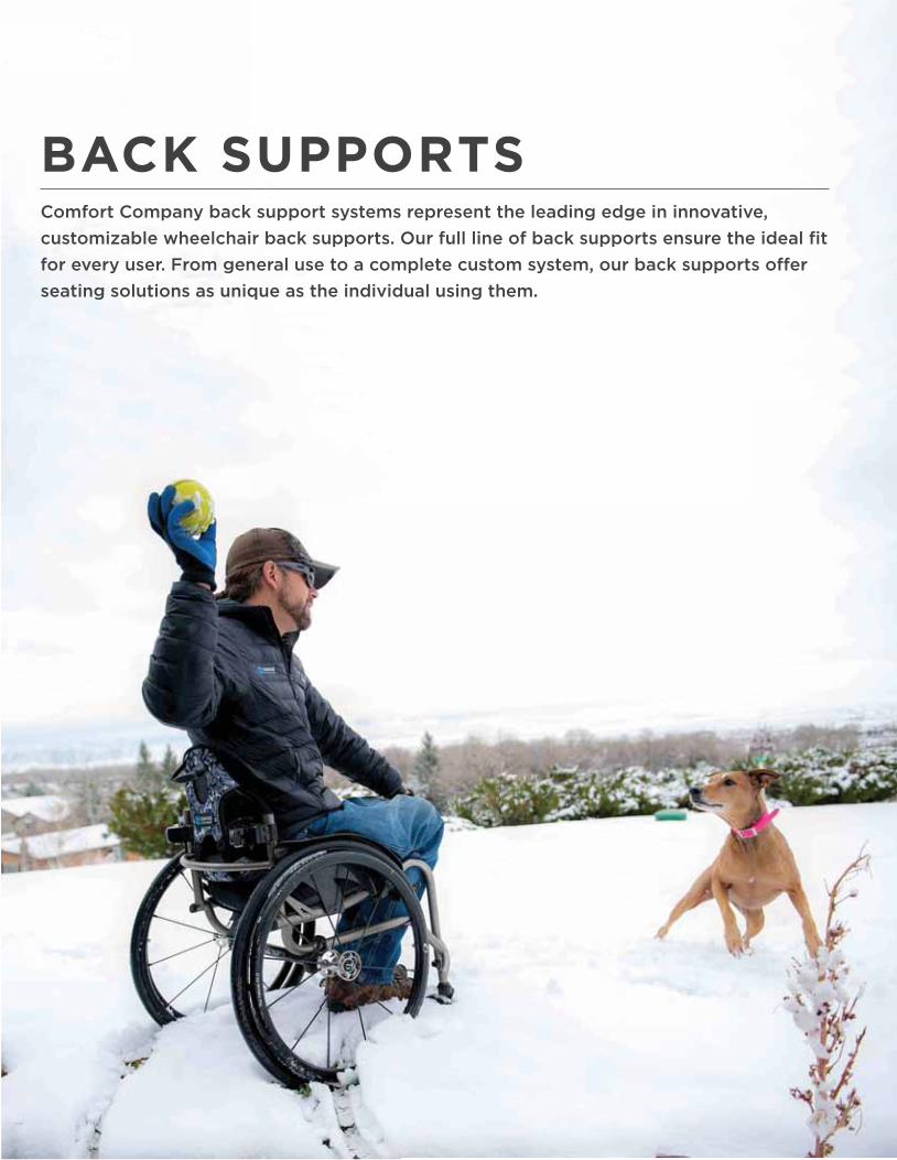
BACK SUPPORTSComfort Company back support systems represent the leading edge in innovative,
customizable wheelchair back supports. Our full line of back supports ensure the ideal fit
for every user. From general use to a complete custom system, our back supports offer
seating solutions as unique as the individual using them.
3
Width and Depth Alignment Marks
Recline Locking Bolts
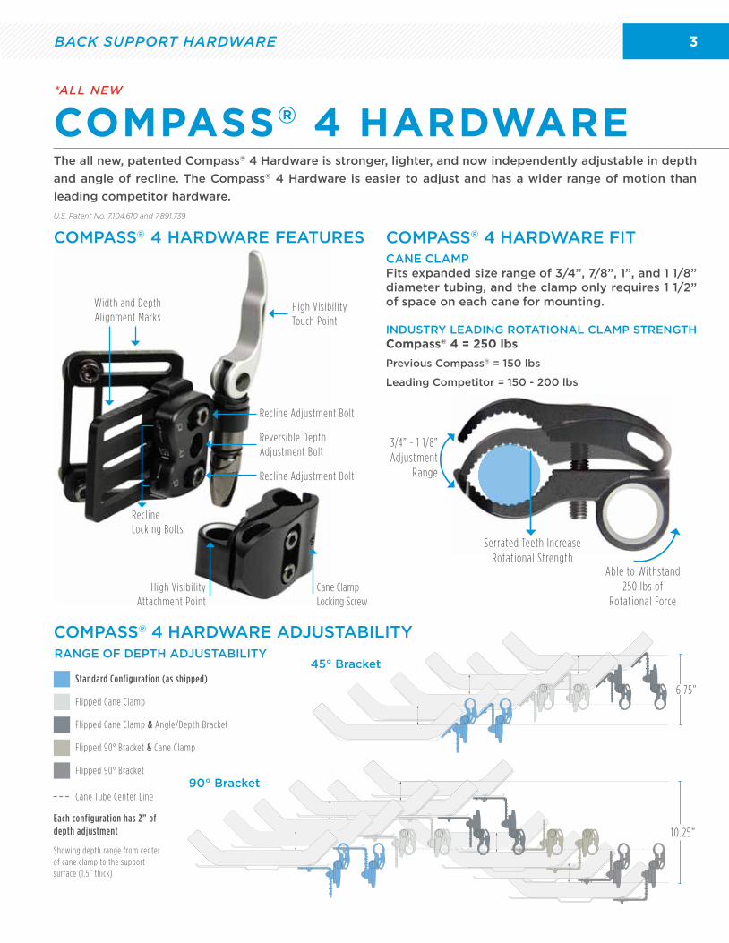
Standard Configuration (as shipped)
Each configuration has 2” of depth adjustment
Showing depth range from center of cane clamp to the support surface (1 .5” thick)
Flipped Cane Clamp
Flipped Cane Clamp & Angle/Depth Bracket
Flipped 90° Bracket & Cane Clamp
Flipped 90° Bracket
Cane Tube Center Line
High Visibility Touch Point
Cane Clamp Locking Screw
Recline Adjustment Bolt
Recline Adjustment Bolt
Reversible Depth Adjustment Bolt
High Visibility Attachment Point
The all new, patented Compass® 4 Hardware is stronger, lighter, and now independently adjustable in depth
and angle of recline. The Compass® 4 Hardware is easier to adjust and has a wider range of motion than
leading competitor hardware.
U.S. Patent No. 7,104,610 and 7,891,739
CANE CLAMP Fits expanded size range of 3/4”, 7/8”, 1”, and 1 1/8” diameter tubing, and the clamp only requires 1 1/2” of space on each cane for mounting.
INDUSTRY LEADING ROTATIONAL CLAMP STRENGTH Compass® 4 = 250 lbs
Previous Compass® = 150 lbs
Leading Competitor = 150 - 200 lbs
BACK SUPPORT HARDWARE
COMPASS® 4 HARDWARE FIT
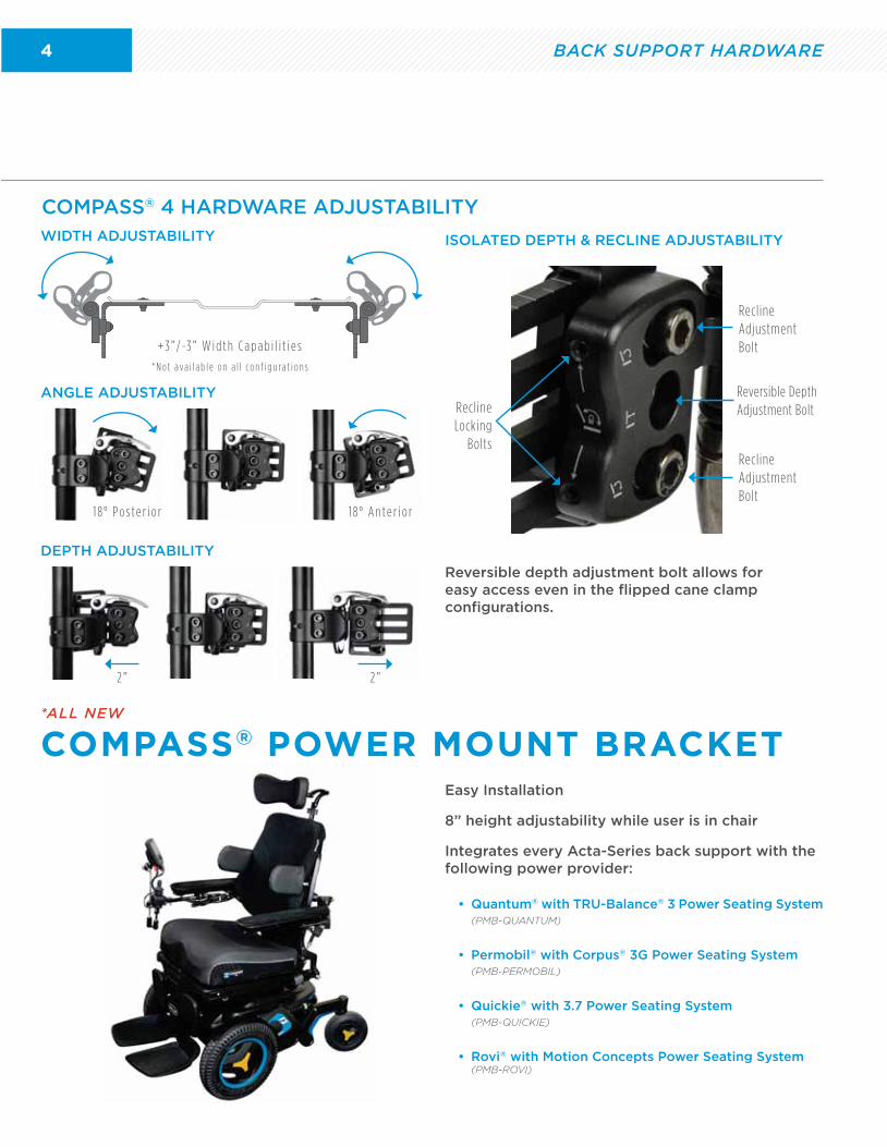
COMPASS® 4 HARDWARE ADJUSTABILITY
45° Bracket
90° Bracket
RANGE OF DEPTH ADJUSTABILITY
COMPASS® 4 HARDWARE FEATURES
COMPASS® 4 HARDWARE*ALL NEW
Serrated Teeth Increase Rotational Strength
3/4” - 1 1/8”Adjustment
Range
Able to Withstand 250 lbs of
Rotational Force
6.75”
10.25”
4
ANGLE ADJUSTABILITY
WIDTH ADJUSTABILITY ISOLATED DEPTH & RECLINE ADJUSTABILITY
COMPASS® 4 HARDWARE ADJUSTABILITY
DEPTH ADJUSTABILITY
Reversible depth adjustment bolt allows for easy access even in the flipped cane clamp configurations.
+ 3 ” / -3 ” W i d t h C a p a b i l i t i e s
* N o t a va i l a b l e o n a l l c o n f i g u ra t i o n s
1 8 ° P o s t e r i o r 1 8 ° A n t e r i o r
2 ” 2 ”
COMPASS® POWER MOUNT BRACKET
Recline Locking
Bolts
Recline Adjustment Bolt
Recline Adjustment Bolt
Reversible Depth Adjustment Bolt
*ALL NEW
Easy Installation
8” height adjustability while user is in chair
Integrates every Acta-Series back support with the following power provider:
• Quantum® with TRU-Balance® 3 Power Seating System(PMB-QUANTUM)
• Permobil® with Corpus® 3G Power Seating System(PMB-PERMOBIL)
• Quickie® with 3.7 Power Seating System(PMB-QUICKIE)
• Rovi® with Motion Concepts Power Seating System(PMB-ROVI)
BACK SUPPORT HARDWARE
5BACK SUPPORT TECHNOLOGY
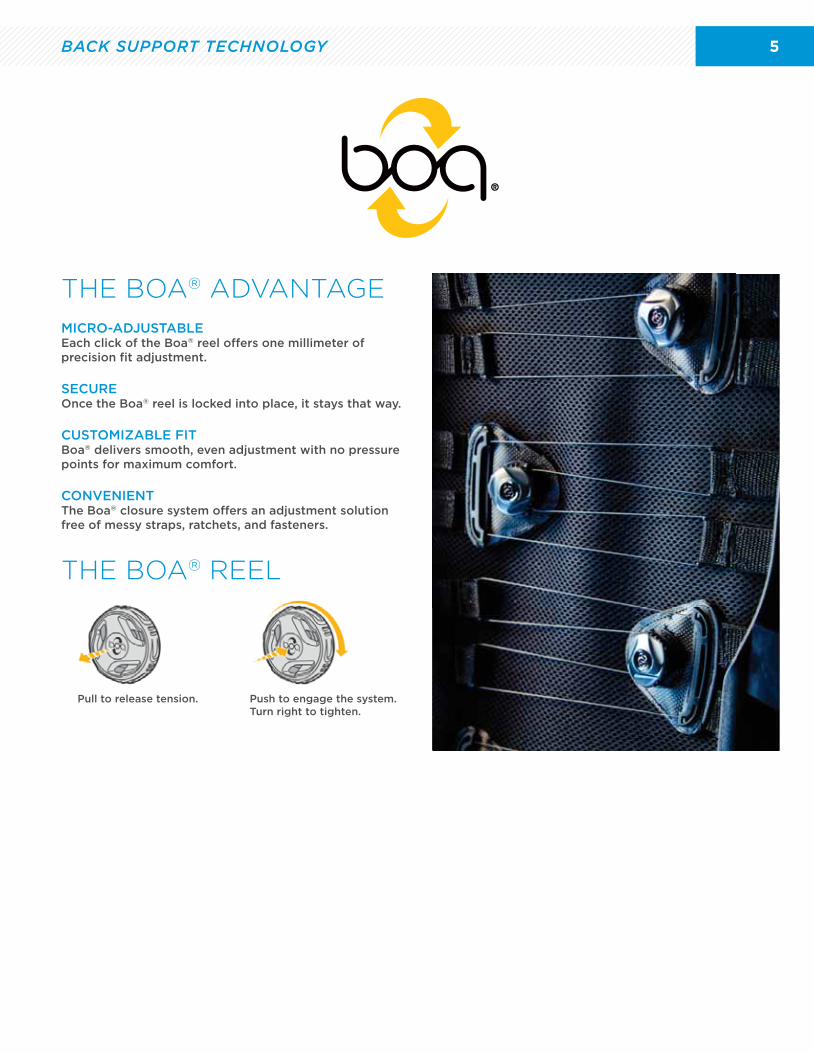
THE BOA® ADVANTAGE
THE BOA® REEL
MICRO-ADJUSTABLEEach click of the Boa® reel offers one millimeter of precision fit adjustment.
SECUREOnce the Boa® reel is locked into place, it stays that way.
CUSTOMIZABLE FITBoa® delivers smooth, even adjustment with no pressure points for maximum comfort.
CONVENIENTThe Boa® closure system offers an adjustment solution free of messy straps, ratchets, and fasteners.
Pull to release tension. Push to engage the system. Turn right to tighten.
6
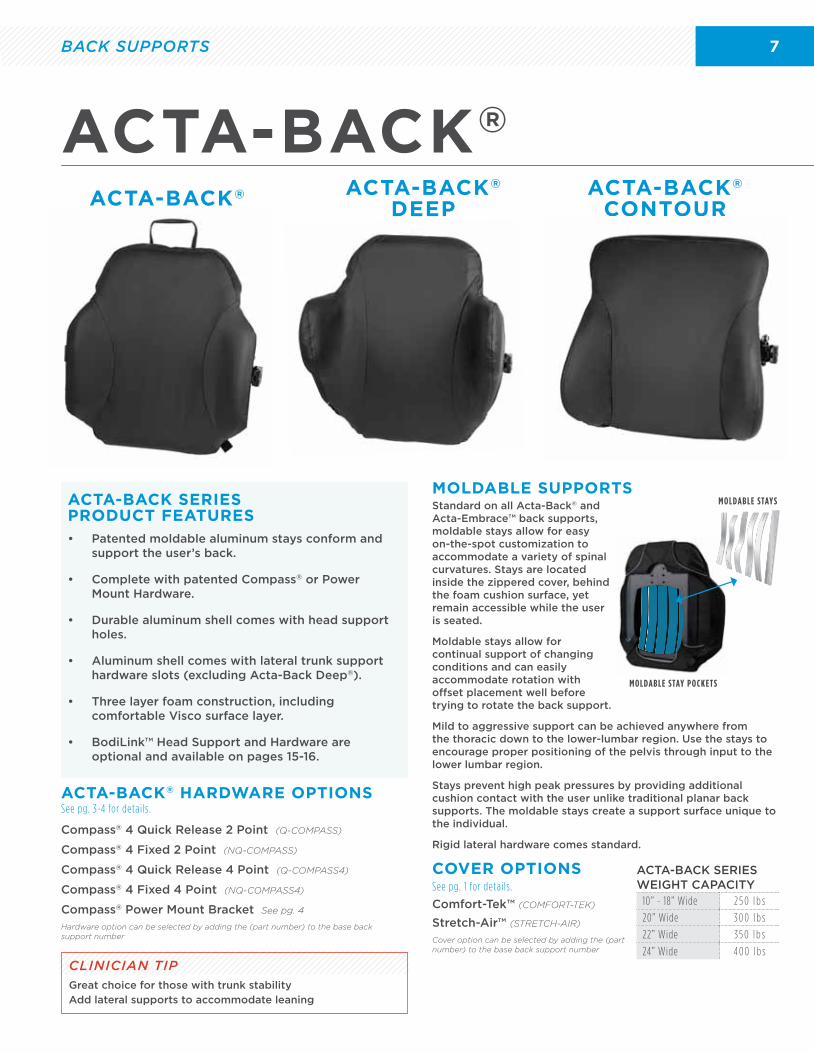
Standard on all Acta-Back® and Acta-Embrace™ back supports, moldable stays allow for easy on-the-spot customization to accommodate a variety of spinal curvatures. Stays are located inside the zippered cover, behind the foam cushion surface, yet remain accessible while the user is seated.
Moldable stays allow for continual support of changing conditions and can easily accommodate rotation with offset placement well before trying to rotate the back support.
Mild to aggressive support can be achieved anywhere from the thoracic down to the lower-lumbar region. Use the stays to encourage proper positioning of the pelvis through input to the lower lumbar region.
Stays prevent high peak pressures by providing additional cushion contact with the user unlike traditional planar back supports. The moldable stays create a support surface unique to the individual.
Each back support comes standard with 2 moldable stays for multiple set up options.
MOLDABLE SUPPORTU.S. Patent No. 6,733,074
MOLDABLE STAY POCKETS
MOLDABLE STAYS
BODILINK™ HEAD SUPPORT PADS & HARDWARE
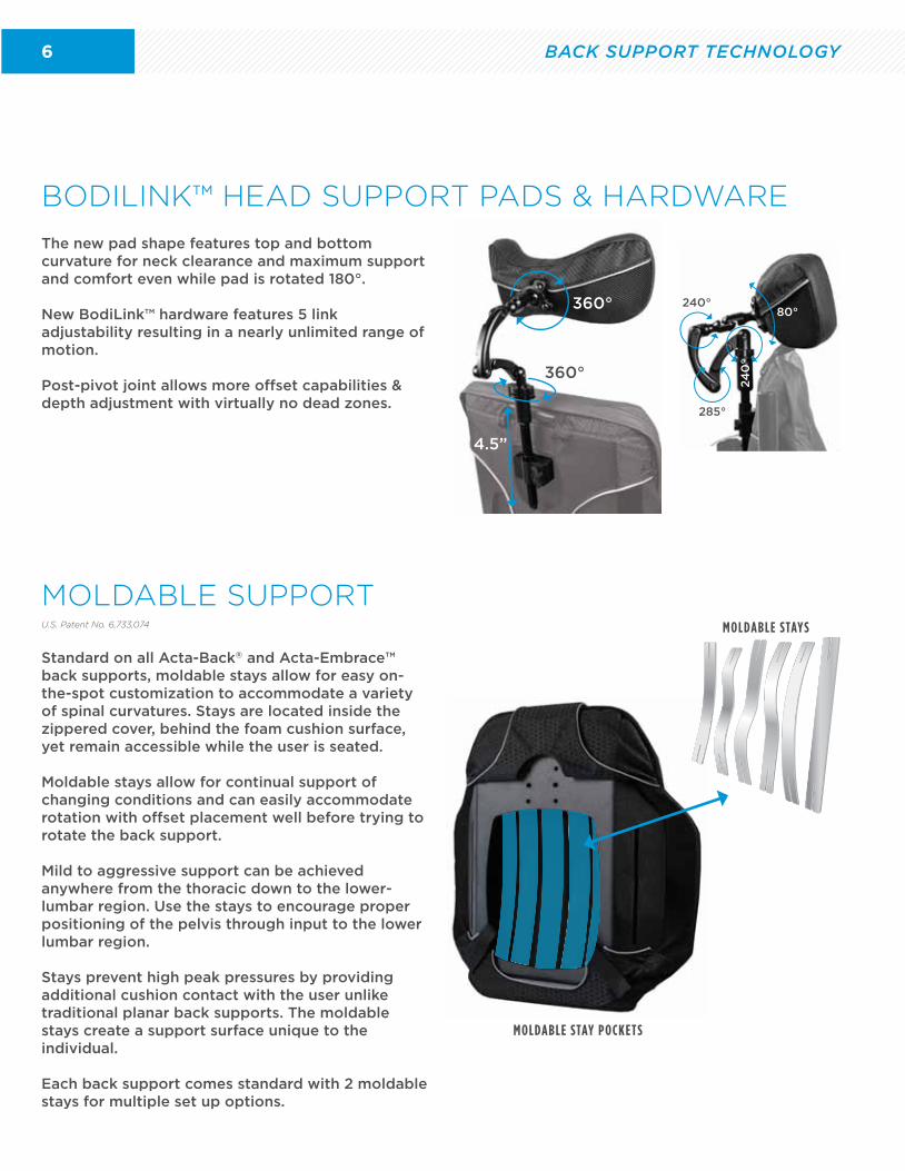
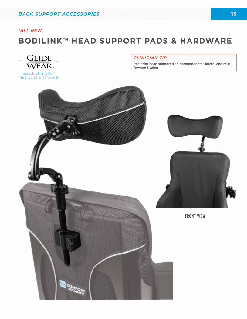
The new pad shape features top and bottom curvature for neck clearance and maximum support and comfort even while pad is rotated 180°.
New BodiLink™ hardware features 5 link adjustability resulting in a nearly unlimited range of motion.
Post-pivot joint allows more offset capabilities & depth adjustment with virtually no dead zones.
285°
240°80°
24
0°
4.5”
360°
360°
BACK SUPPORT TECHNOLOGY
7
ACTA-BACK®
ACTA-BACK®
CLINICIAN TIPGreat choice for those with trunk stability
Add lateral supports to accommodate leaning
ACTA-BACK®
DEEPACTA-BACK®
CONTOURCONTOUR
ACTA-BACK SERIES PRODUCT FEATURES
Compass® 4 Quick Release 2 Point (Q-COMPASS)
Compass® 4 Fixed 2 Point (NQ-COMPASS)
Compass® 4 Quick Release 4 Point (Q-COMPASS4)
Compass® 4 Fixed 4 Point (NQ-COMPASS4)
Compass® Power Mount Bracket See pg. 4
Hardware option can be selected by adding the (part number) to the base back support number
Comfort-Tek™ (COMFORT-TEK)
Stretch-Air™ (STRETCH-AIR)
Cover option can be selected by adding the (part number) to the base back support number
ACTA-BACK® HARDWARE OPTIONS See pg. 3-4 for details.
COVER OPTIONS
Standard on all Acta-Back® and Acta-Embrace™ back supports, moldable stays allow for easy on-the-spot customization to accommodate a variety of spinal curvatures. Stays are located inside the zippered cover, behind the foam cushion surface, yet remain accessible while the user is seated.
Moldable stays allow for continual support of changing conditions and can easily accommodate rotation with offset placement well before trying to rotate the back support.
Mild to aggressive support can be achieved anywhere from the thoracic down to the lower-lumbar region. Use the stays to encourage proper positioning of the pelvis through input to the lower lumbar region.
Stays prevent high peak pressures by providing additional cushion contact with the user unlike traditional planar back supports. The moldable stays create a support surface unique to the individual.
Rigid lateral hardware comes standard.
MOLDABLE SUPPORTS
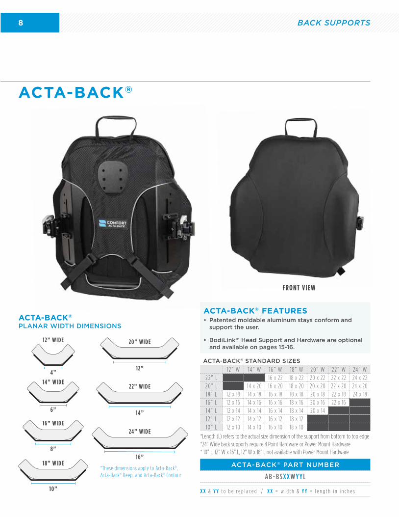
• Patented moldable aluminum stays conform and support the user’s back.
• Complete with patented Compass® or Power Mount Hardware.
• Durable aluminum shell comes with head support holes.
• Aluminum shell comes with lateral trunk support hardware slots (excluding Acta-Back Deep®).
• Three layer foam construction, including comfortable Visco surface layer.
• BodiLink™ Head Support and Hardware are optional and available on pages 15-16.
ACTA-BACK SERIES WEIGHT CAPACITY
10” - 18” Wide 2 5 0 l b s
20” Wide 3 0 0 l b s
22” Wide 3 5 0 l b s
24” Wide 4 0 0 l b s
See pg. 1 for details.
BACK SUPPORTS
8
ACTA-BACK®
FRONT VIEWFRONT VIEW
• Patented moldable aluminum stays conform and support the user.
• BodiLink™ Head Support and Hardware are optional and available on pages 15-16.
ACTA-BACK® FEATURES
ACTA-BACK® PART NUMBER
A B - B S X X W Y Y L
ACTA-BACK®
PLANAR WIDTH DIMENSIONS
ACTA-BACK® STANDARD SIZES
1 2 ” W 1 4 ” W 1 6 ” W 1 8 ” W 2 0 ” W 2 2 ” W 24 ” W2 2 ” L 16 x 22 18 x 22 20 x 22 22 x 22 24 x 222 0 ” L 14 x 20 16 x 20 18 x 20 20 x 20 22 x 20 24 x 201 8 ” L 12 x 18 14 x 18 16 x 18 18 x 18 20 x 18 22 x 18 24 x 181 6 ” L 12 x 16 14 x 16 16 x 16 18 x 16 20 x 16 22 x 161 4 ” L 12 x 14 14 x 14 16 x 14 18 x 14 20 x 141 2 ” L 12 x 12 14 x 12 16 x 12 18 x 121 0 ” L 12 x 10 14 x 10 16 x 10 18 x 10
X X & Y Y t o b e r e p l a c e d / X X = w i d t h & Y Y = l e n g t h i n i n c h e s
*Length (L) refers to the actual size dimension of the support from bottom to top edge*24” Wide back supports require 4 Point Hardware or Power Mount Hardware* 10” L, 12” W x 16” L, 12” W x 18” L not available with Power Mount Hardware
12” WIDE
4”
16” WIDE
8”
20” WIDE
12”
6”
14” WIDE
18” WIDE
10”
22” WIDE
14”
24” WIDE
16”
*These dimensions apply to Acta-Back®, Acta-Back® Deep, and Acta-Back® Contour
BACK SUPPORTS

9
FRONT VIEW
ACTA-BACK® DEEP
9” 11” 12”
13” 14”
LATERAL SUPPORT HEIGHT
• Acta-Back® Deep wings are angle and width adjustable up to 2” featuring a thin profile for greater range of motion. Wings are not height adjustable.
ACTA-BACK® DEEP FEATURES
ACTA-BACK® DEEP PART NUMBER
L a t e ra l S i z e P a r t N u m b e r3” D x 5” L Lateral A B D 3 - B S X X W Y Y L5” D x 6” L Lateral A B D 5 - B S X X W Y Y L7” D x 7” L Lateral A B D 7- B S X X W Y Y L13”
5” L
3” D
3” LATERAL DEPTH 5” LATERAL DEPTH
5” D
6” L
7” LATERAL DEPTH
7” D
7” L
ACTA-BACK® DEEPLATERAL SUPPORT DIMENSIONS
LATERAL SUPPORT DIMENSIONS
“D” Dimensions
3 ” , 5 ” , o r 7 ”
18” WIDTH12” WIDTH 14” WIDTH 16” WIDTH
9” Max7” Min
D
11” Max9” Min
D
13” Max11” Min
D
15” Max13” Min
D
20” WIDTH 22” WIDTH
17” Max15” Min
D
19” Max17” Min
D
ACTA-BACK® DEEP STANDARD SIZES
1 2 ” W 1 4 ” W 1 6 ” W 1 8 ” W 2 0 ” W 2 2 ” W 24 ” W2 2 ” L 16 x 22 18 x 22 20 x 22 22 x 22 24 x 222 0 ” L 14 x 20 16 x 20 18 x 20 20 x 20 22 x 20 24 x 201 8 ” L 12 x 18 14 x 18 16 x 18 18 x 18 20 x 18 22 x 18 24 x 181 6 ” L 12 x 16 14 x 16 16 x 16 18 x 16 20 x 16 22 x 161 4 ” L 12 x 14 14 x 14 16 x 14 18 x 14 20 x 141 2 ” L 12 x 12 14 x 12 16 x 12 18 x 12
X X & Y Y t o b e r e p l a c e d / X X = w i d t h & Y Y = l e n g t h i n i n c h e s
*Length (L) refers to the actual size dimension of the support from bottom to top edge
*12” Tall back supports require 2 Point Hardware
*24” Wide back supports require 4 Point Hardware or Power Mount Hardware
*12”W x 12”L, 12”W x 14”L, 14”W x 12”L, & 14”W x 14”L require 5”D x 6”L or 3”D x 5”L Laterals
*12”W x 16”L & 12”W x 18”L back supports are not available with Power Mount Hardware12” LENGTH 14” LENGTH 16” LENGTH
18” LENGTH 20” LENGTH 22” LENGTH
ACTA-BACK®
BACK SUPPORTS
10 BACK SUPPORTS
ACTA-BACK® CONTOUR
FRONT VIEWFRONT VIEW
ACTA BACK CONTOU
ACTA-BACK® CONTOUR PART NUMBER
L a t e ra l D e p t h P a r t N u m b e r
5” Lateral Depth A B C 5 - B S X X W Y Y L8” Lateral Depth A B C 8 - B S X X W Y Y L
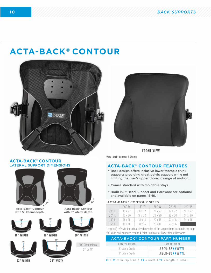
• Back design offers inclusive lower thoracic trunk supports providing great pelvic support while not limiting the user’s upper thoracic range of motion.
• Comes standard with moldable stays.
• BodiLink™ Head Support and Hardware are optional and available on pages 15-16.
ACTA-BACK® CONTOUR FEATURESACTA-BACK® CONTOUR LATERAL SUPPORT DIMENSIONS
5”
Acta-Back® Contour with 5” lateral depth.
8”
Acta-Back® Contour with 8” lateral depth.
ACTA-BACK® CONTOUR SIZES
1 6 ” W 1 8 ” W 2 0 ” W 2 2 ” W 24 ” W2 2 ” L 16 x 22 18 x 22 20 x 22 22 x 22 24 x 2 22 0 ” L 16 x 20 18 x 20 20 x 20 22 x 20 24 x 2 01 8 ” L 16 x 18 18 x 18 20 x 18 22 x 18 24 x 1 81 6 ” L 16 x 16 18 x 16 20 x 16 22 x 16
X X & Y Y t o b e r e p l a c e d / X X = w i d t h & Y Y = l e n g t h i n i n c h e s
*Length (L) refers to the actual size dimension of the support from bottom to top edge*24” Wide back supports require 4 Point Hardware or Power Mount Hardware
*Acta-Back® Contour 5 Shown
“D” Dimensions
5 ” o r 8 ”
16” WIDTH 18” WIDTH
22” WIDTH 24” WIDTH
10”
D
12”
D
20” WIDTH
14”
D
16”
D
18”
D
11
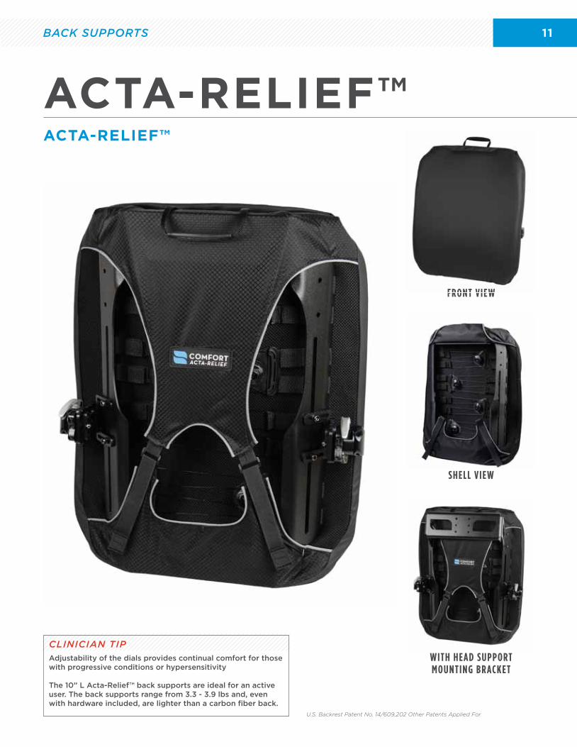
ACTA-RELIEF™
FRONT VIEW
SHELL VIEW
FRONT VIEW
WITH HEAD SUPPORT MOUNTING BRACKET
ACTA-RELIEF™
U.S. Backrest Patent No. 14/609,202 Other Patents Applied For
CLINICIAN TIPAdjustability of the dials provides continual comfort for those with progressive conditions or hypersensitivity
The 10” L Acta-Relief™ back supports are ideal for an active user. The back supports range from 3.3 - 3.9 lbs and, even with hardware included, are lighter than a carbon fiber back.
BACK SUPPORTS
12
ACTA-RELIEF™ PART NUMBER
A R - B S X X W Y Y L
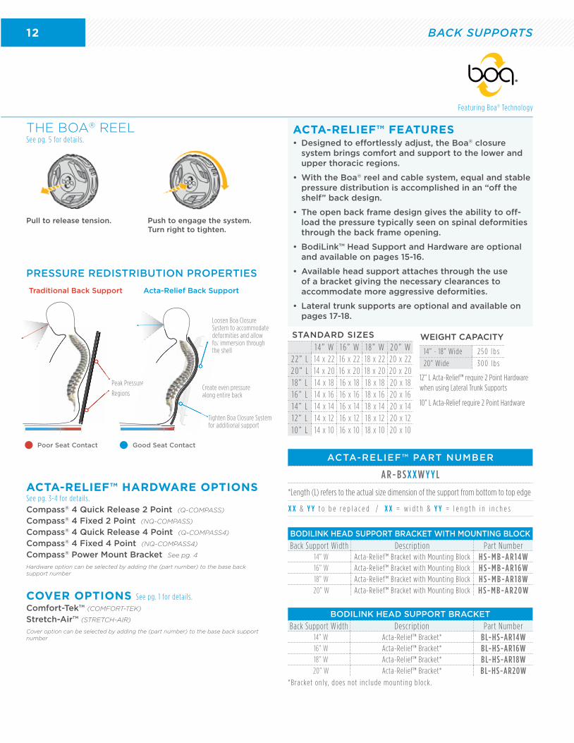
• Designed to effortlessly adjust, the Boa® closure system brings comfort and support to the lower and upper thoracic regions.
• With the Boa® reel and cable system, equal and stable pressure distribution is accomplished in an “off the shelf” back design.
• The open back frame design gives the ability to off-load the pressure typically seen on spinal deformities through the back frame opening.
• BodiLink™ Head Support and Hardware are optional and available on pages 15-16.
• Available head support attaches through the use of a bracket giving the necessary clearances to accommodate more aggressive deformities.
• Lateral trunk supports are optional and available on pages 17-18.
ACTA-RELIEF™ FEATURES
Featuring Boa® Technology
STANDARD SIZES
1 4 ” W 1 6 ” W 1 8 ” W 2 0 ” W2 2 ” L 14 x 22 16 x 22 18 x 22 20 x 222 0 ” L 14 x 20 16 x 20 18 x 20 20 x 201 8 ” L 14 x 18 16 x 18 18 x 18 20 x 181 6 ” L 14 x 16 16 x 16 18 x 16 20 x 161 4 ” L 14 x 14 16 x 14 18 x 14 20 x 141 2 ” L 14 x 12 16 x 12 18 x 12 20 x 121 0 ” L 14 x 10 16 x 10 18 x 10 20 x 10
X X & Y Y t o b e r e p l a c e d / X X = w i d t h & Y Y = l e n g t h i n i n c h e s
*Length (L) refers to the actual size dimension of the support from bottom to top edge
12” L Acta-Relief™ require 2 Point Hardware when using Lateral Trunk Supports
10” L Acta-Relief require 2 Point Hardware
ACTA-RELIEF™ HARDWARE OPTIONS See pg. 3-4 for details.
Compass® 4 Quick Release 2 Point (Q-COMPASS)
Compass® 4 Fixed 2 Point (NQ-COMPASS)
Compass® 4 Quick Release 4 Point (Q-COMPASS4)
Compass® 4 Fixed 4 Point (NQ-COMPASS4)
Compass® Power Mount Bracket See pg. 4
Hardware option can be selected by adding the (part number) to the base back support number
COVER OPTIONS See pg. 1 for details.
Comfort-Tek™ (COMFORT-TEK)
Stretch-Air™ (STRETCH-AIR)
Cover option can be selected by adding the (part number) to the base back support number
BODILINK HEAD SUPPORT BRACKET WITH MOUNTING BLOCK
Back Support Width Description Part Number14” W Acta-Relief™ Bracket with Mounting Block H S - M B -A R 1 4 W16” W Acta-Relief™ Bracket with Mounting Block H S - M B -A R 1 6 W18” W Acta-Relief™ Bracket with Mounting Block H S - M B -A R 1 8 W20” W Acta-Relief™ Bracket with Mounting Block H S - M B -A R 2 0 W
BODILINK HEAD SUPPORT BRACKET
Back Support Width Description Part Number14” W Acta-Relief™ Bracket* BL-HS-AR14W16” W Acta-Relief™ Bracket* BL-HS-AR16W18” W Acta-Relief™ Bracket* BL-HS-AR18W20” W Acta-Relief™ Bracket* BL-HS-AR20W
WEIGHT CAPACITY
14” - 18” Wide 2 5 0 l b s
20” Wide 3 0 0 l b s
*Bracket on ly, does not inc lude mount ing b lock .
PRESSURE REDISTRIBUTION PROPERTIES
THE BOA® REELSee pg. 5 for details.
Pull to release tension. Push to engage the system. Turn right to tighten.
Peak Pressure
Regions
Traditional Back Support
Tighten Boa Closure System for additional support
Create even pressurealong entire back
Loosen Boa Closure System to accommodate deformities and allow for immersion through the shell
Acta-Relief Back Support
Good Seat ContactPoor Seat Contact
re Creal
forth
BACK SUPPORTS
13
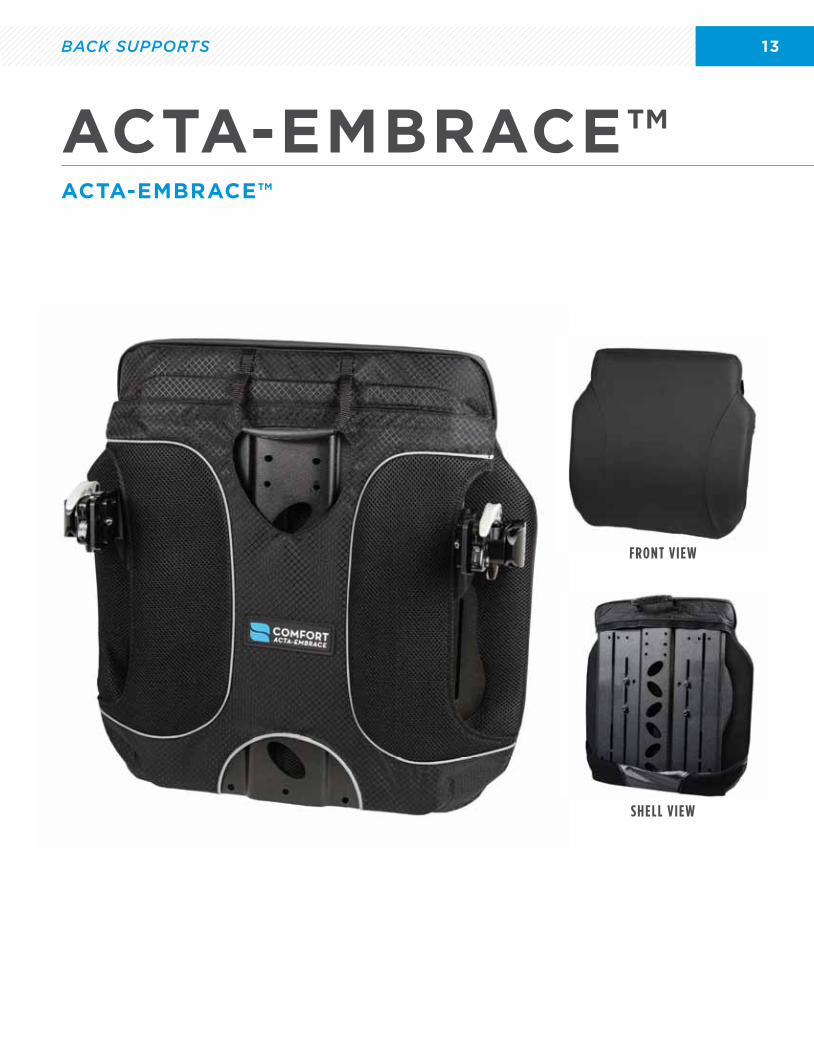
ACTA-EMBRACE™
FRONT VIEW
SHELL VIEW
FRONT VIEW
ACTA-EMBRACE™
BACK SUPPORTS
14
WEIGHT CAPACITY
10” - 18” Wide 2 5 0 l b s
20” Wide 3 0 0 l b s
22” Wide 3 5 0 l b s
24” Wide 4 0 0 l b s
ACTA-EMBRACE™ PART NUMBER
A E - B S X X W Y Y L
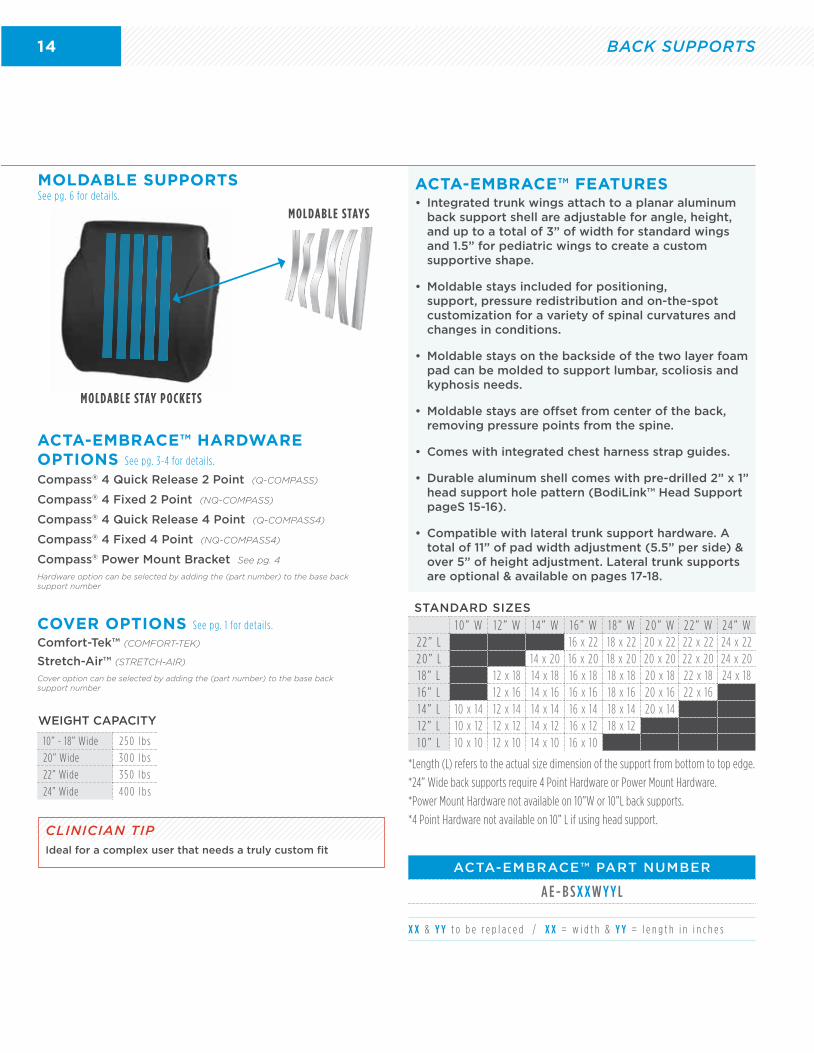
• Integrated trunk wings attach to a planar aluminum back support shell are adjustable for angle, height, and up to a total of 3” of width for standard wings and 1.5” for pediatric wings to create a custom supportive shape.
• Moldable stays included for positioning, support, pressure redistribution and on-the-spot customization for a variety of spinal curvatures and changes in conditions.
• Moldable stays on the backside of the two layer foam pad can be molded to support lumbar, scoliosis and kyphosis needs.
• Moldable stays are offset from center of the back, removing pressure points from the spine.
• Comes with integrated chest harness strap guides.
• Durable aluminum shell comes with pre-drilled 2” x 1” head support hole pattern (BodiLink™ Head Support pageS 15-16).
• Compatible with lateral trunk support hardware. A total of 11” of pad width adjustment (5.5” per side) & over 5” of height adjustment. Lateral trunk supports are optional & available on pages 17-18.
ACTA-EMBRACE™ FEATURES
STANDARD SIZES
1 0 ” W 1 2 ” W 1 4 ” W 1 6 ” W 1 8 ” W 2 0 ” W 2 2 ” W 24 ” W2 2 ” L 16 x 22 18 x 22 20 x 22 22 x 22 24 x 222 0 ” L 14 x 20 16 x 20 18 x 20 20 x 20 22 x 20 24 x 201 8 ” L 12 x 18 14 x 18 16 x 18 18 x 18 20 x 18 22 x 18 24 x 181 6 ” L 12 x 16 14 x 16 16 x 16 18 x 16 20 x 16 22 x 161 4 ” L 10 x 14 12 x 14 14 x 14 16 x 14 18 x 14 20 x 141 2 ” L 10 x 12 12 x 12 14 x 12 16 x 12 18 x 121 0 ” L 10 x 10 12 x 10 14 x 10 16 x 10
X X & Y Y t o b e r e p l a c e d / X X = w i d t h & Y Y = l e n g t h i n i n c h e s
*Length (L) refers to the actual size dimension of the support from bottom to top edge.
*24” Wide back supports require 4 Point Hardware or Power Mount Hardware.
*Power Mount Hardware not available on 10”W or 10”L back supports.
*4 Point Hardware not available on 10” L if using head support.
Compass® 4 Quick Release 2 Point (Q-COMPASS)
Compass® 4 Fixed 2 Point (NQ-COMPASS)
Compass® 4 Quick Release 4 Point (Q-COMPASS4)
Compass® 4 Fixed 4 Point (NQ-COMPASS4)
Compass® Power Mount Bracket See pg. 4
Hardware option can be selected by adding the (part number) to the base back support number
Comfort-Tek™ (COMFORT-TEK)
Stretch-Air™ (STRETCH-AIR)
Cover option can be selected by adding the (part number) to the base back support number
ACTA-EMBRACE™ HARDWARE OPTIONS See pg. 3-4 for details.
COVER OPTIONS See pg. 1 for details.
CLINICIAN TIPIdeal for a complex user that needs a truly custom fit
MOLDABLE SUPPORTS See pg. 6 for details.
BACK SUPPORTS
15
BODILINK™ HEAD SUPPORT PADS & HARDWARE
FRONT VIEW
Available with GlideWear® Technology. See pg. 20 for details.
*ALL NEW
BACK SUPPORT ACCESSORIES
CLINICIAN TIPPosterior head support also accommodates lateral and mild forward flexion
16
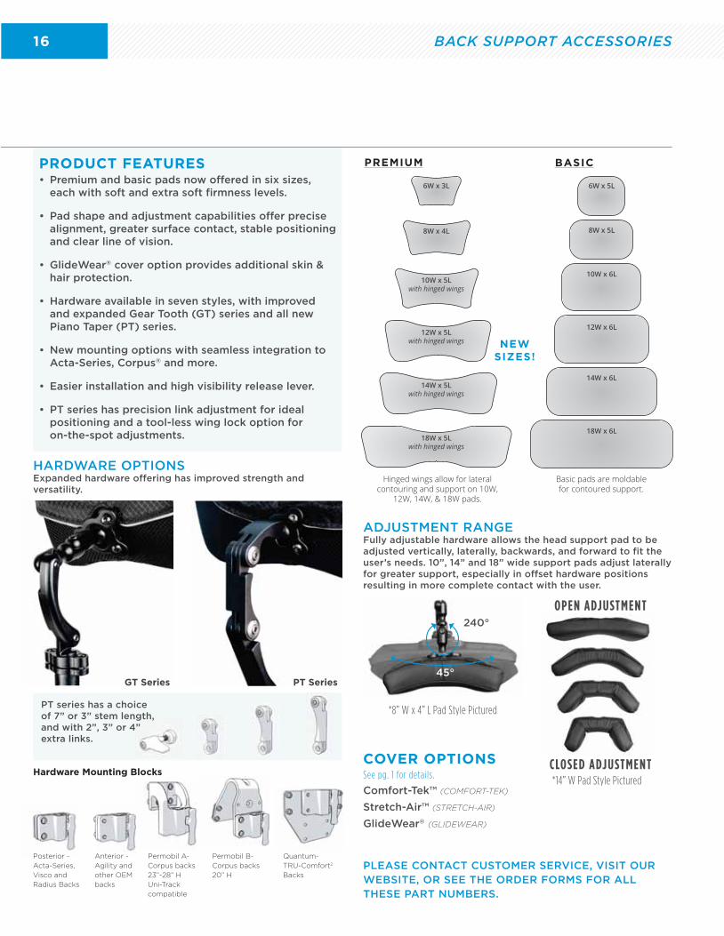
• Premium and basic pads now offered in six sizes, each with soft and extra soft firmness levels.
• Pad shape and adjustment capabilities offer precise alignment, greater surface contact, stable positioning and clear line of vision.
• GlideWear® cover option provides additional skin & hair protection.
• Hardware available in seven styles, with improved and expanded Gear Tooth (GT) series and all new Piano Taper (PT) series.
• New mounting options with seamless integration to Acta-Series, Corpus® and more.
• Easier installation and high visibility release lever.
• PT series has precision link adjustment for ideal positioning and a tool-less wing lock option for on-the-spot adjustments.
PRODUCT FEATURES
HARDWARE OPTIONSExpanded hardware offering has improved strength and versatility.
*8” W x 4” L Pad Style Pictured
ADJUSTMENT RANGEFully adjustable hardware allows the head support pad to be adjusted vertically, laterally, backwards, and forward to fit the user’s needs. 10”, 14” and 18” wide support pads adjust laterally for greater support, especially in offset hardware positions resulting in more complete contact with the user.
OPEN ADJUSTMENT
CLOSED ADJUSTMENT*14” W Pad Style Pictured
240°
45°
Comfort-Tek™ (COMFORT-TEK)
Stretch-Air™ (STRETCH-AIR)
GlideWear® (GLIDEWEAR)
COVER OPTIONSSee pg. 1 for details.
PT Series
6W x 5L
8W x 5L
12W x 6L
10W x 6L
14W x 6L
18W x 6L
6W x 3L
8W x 4L
12W x 5Lwith hinged wings
10W x 5Lwith hinged wings
14W x 5L with hinged wings
18W x 5L with hinged wings
Hinged wings allow for lateral contouring and support on 10W,
12W, 14W, & 18W pads.
Basic pads are moldable for contoured support.
NEWSIZES!
GT Series
PREMIUM BASIC
PT series has a choice of 7” or 3” stem length, and with 2”, 3” or 4” extra links.
PLEASE CONTACT CUSTOMER SERVICE, VISIT OUR WEBSITE, OR SEE THE ORDER FORMS FOR ALL THESE PART NUMBERS.
Hardware Mounting Blocks
Posterior -
Acta-Series,
Visco and
Radius Backs
Anterior -
Agility and
other OEM
backs
Permobil A-
Corpus backs
23”-28” H
Uni-Track
compatible
Permobil B-
Corpus backs
20” H
Quantum-
TRU-Comfort2
Backs
BACK SUPPORT ACCESSORIES
17
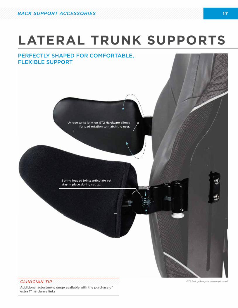
GT2 Swing-Away Hardware pictured
Unique wrist joint on GT2 Hardware allows for pad rotation to match the user.
Spring loaded joints articulate yet stay in place during set up.
LATERAL TRUNK SUPPORTS
CLINICIAN TIPAdditional adjustment range available with the purchase of extra 1” hardware links
BACK SUPPORT ACCESSORIES
PERFECTLY SHAPED FOR COMFORTABLE, FLEXIBLE SUPPORT
18
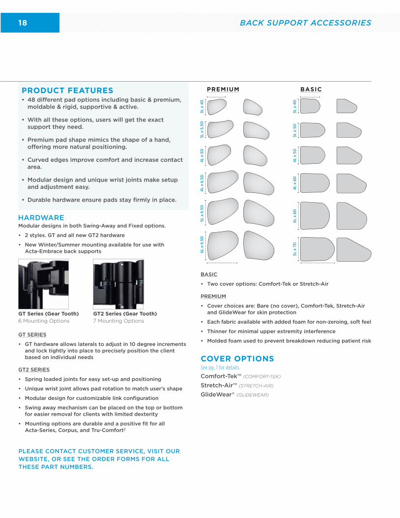
• 48 different pad options including basic & premium, moldable & rigid, supportive & active.
• With all these options, users will get the exact support they need.
• Premium pad shape mimics the shape of a hand, offering more natural positioning.
• Curved edges improve comfort and increase contact area.
• Modular design and unique wrist joints make setup and adjustment easy.
• Durable hardware ensure pads stay firmly in place.
PRODUCT FEATURES
Comfort-Tek™ (COMFORT-TEK)
Stretch-Air™ (STRETCH-AIR)
GlideWear® (GLIDEWEAR)
COVER OPTIONSSee pg. 1 for details.
PLEASE CONTACT CUSTOMER SERVICE, VISIT OUR WEBSITE, OR SEE THE ORDER FORMS FOR ALL THESE PART NUMBERS.
GT SERIES
• GT hardware allows laterals to adjust in 10 degree increments and lock tightly into place to precisely position the client based on individual needs
GT2 SERIES
• Spring loaded joints for easy set-up and positioning
• Unique wrist joint allows pad rotation to match user’s shape
• Modular design for customizable link configuration
• Swing away mechanism can be placed on the top or bottom for easier removal for clients with limited dexterity
• Mounting options are durable and a positive fit for all Acta-Series, Corpus, and Tru-Comfort2
BASIC
• Two cover options: Comfort-Tek or Stretch-Air
PREMIUM
• Cover choices are: Bare (no cover), Comfort-Tek, Stretch-Air and GlideWear for skin protection
• Each fabric available with added foam for non-zeroing, soft feel
• Thinner for minimal upper extremity interference
• Molded foam used to prevent breakdown reducing patient risk
3L x
4D
3L x
4D
4L x
6.5
D
4L x
6D
3L x
5.5
D
3L x
5D
5L x
6.5
D
6L x
6D
4L x
5D
4L x
5D
6L x
6.5
D
5L x
7D
PREMIUM BASIC
HARDWARE
GT Series (Gear Tooth) 6 Mounting Options
Modular designs in both Swing-Away and Fixed options.
• 2 styles. GT and all new GT2 hardware
• New Winter/Summer mounting available for use with Acta-Embrace back supports
GT2 Series (Gear Tooth) 7 Mounting Options
BACK SUPPORT ACCESSORIES
19
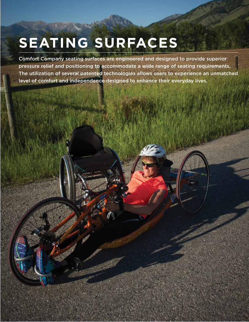
SEATING SURFACESComfort Company seating surfaces are engineered and designed to provide superior
pressure relief and positioning to accommodate a wide range of seating requirements.
The utilization of several patented technologies allows users to experience an unmatched
level of comfort and independence designed to enhance their everyday lives.
20
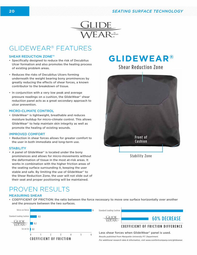
GLIDEWEAR®
Shear Reduct ion Zone
S t a b i l i t y Zo n e
F r o n t o f C u s h i o n
SHEAR REDUCTION ZONE™• Specifically designed to reduce the risk of Decubitus
Ulcer formation and also promotes the healing process of existing problem areas.
• Reduces the risks of Decubitus Ulcers forming underneath the weight bearing bony prominences by greatly reducing the effects of shear forces, a known contributor to the breakdown of tissue.
• In conjunction with a very low peak and average
pressure readings on a cushion, the GlideWear® shear reduction panel acts as a great secondary approach to ulcer prevention.
MICRO-CLIMATE CONTROL• GlideWear® is lightweight, breathable and reduces
moisture buildup for micro-climate control. This allows
GlideWear® to help maintain skin integrity as well as
promote the healing of existing wounds.
IMPROVED COMFORT• Reduction in shear forces allows for greater comfort to
the user in both immediate and long-term use.
STABILITY• A panel of GlideWear® is located under the bony
prominences and allows for micro-movements without the deformation of tissue in the most at-risk areas. It works in combination with the higher friction areas of the seating surface surrounding it, keeping the user
stable and safe. By limiting the use of GlideWear® to the Shear Reduction Zone, the user will not slide out of their seat and proper positioning will be maintained.
GLIDEWEAR® FEATURES
MEASURING SHEAR• COEFFICIENT OF FRICTION: the ratio between the force necessary to move one surface horizontally over another
and the pressure between the two surfaces.
PROVEN RESULTS
Less shear forces when GlideWear® panel is used. Results published from Marquette University P.T. Department.
For additional research data & information, visit www.comfortcompany.com/glidewear.
C O E F F I C I E N T O F F R I C T I O N D I F F E R E N C E
Standard Leading Cushion
60% DECREASE
C O E F F I C I E N T O F F R I C T I O N0 1 2 3 4 5 6
Velcro on Velcro
Standard Leading Cushion
Ice on Ice 0.1
0.2
0.5
6
SEATING SURFACE TECHNOLOGY
21
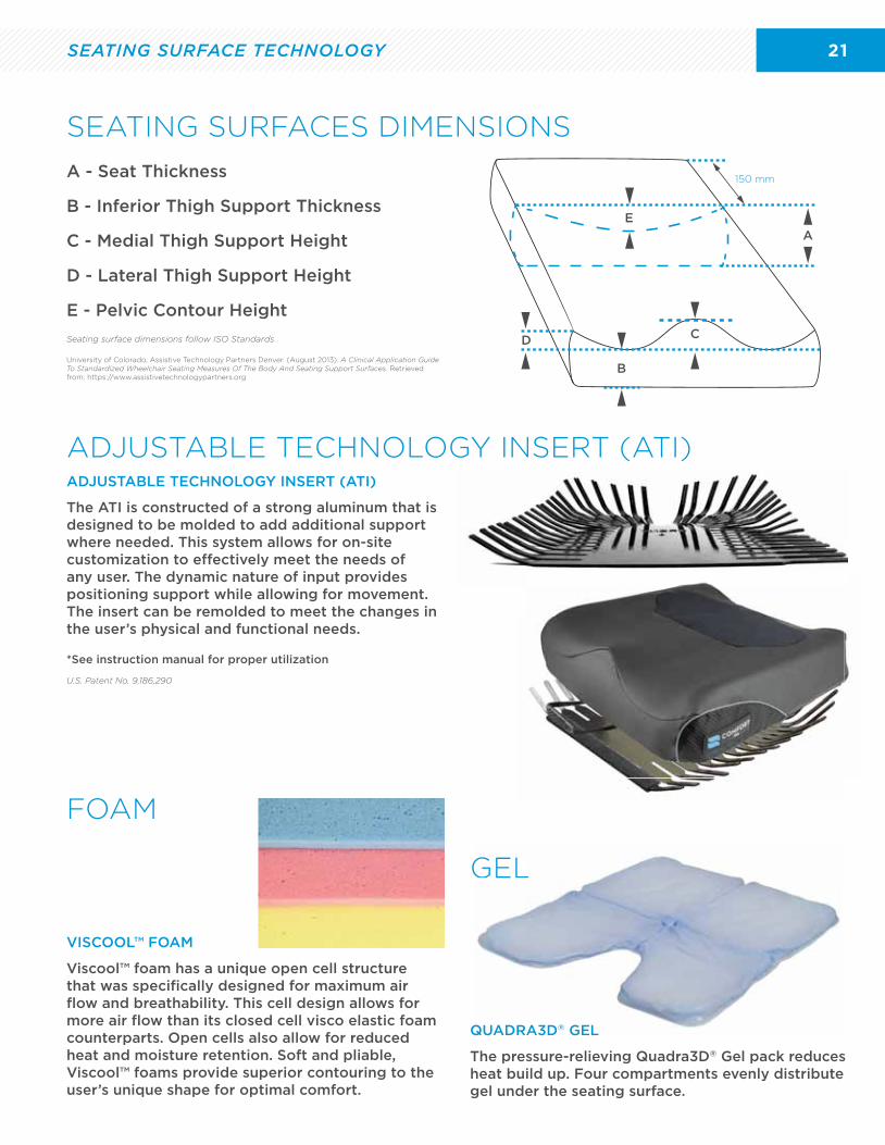
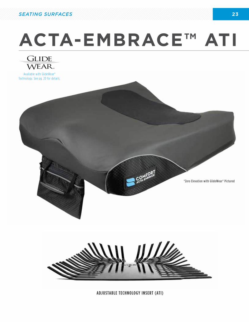
ADJUSTABLE TECHNOLOGY INSERT (ATI)
The ATI is constructed of a strong aluminum that is designed to be molded to add additional support where needed. This system allows for on-site customization to effectively meet the needs of any user. The dynamic nature of input provides positioning support while allowing for movement. The insert can be remolded to meet the changes in the user’s physical and functional needs.
*See instruction manual for proper utilization
U.S. Patent No. 9,186,290
SEATING SURFACE TECHNOLOGY
ADJUSTABLE TECHNOLOGY INSERT (ATI)
SEATING SURFACES DIMENSIONS
A
E
D
B
C
150 mmA - Seat Thickness
B - Inferior Thigh Support Thickness
C - Medial Thigh Support Height
D - Lateral Thigh Support Height
E - Pelvic Contour Height
Seating surface dimensions follow ISO Standards
University of Colorado, Assistive Technology Partners Denver. (August 2013). A Clinical Application Guide To Standardized Wheelchair Seating Measures Of The Body And Seating Support Surfaces. Retrieved from: https://www.assistivetechnologypartners.org
QUADRA3D® GEL
The pressure-relieving Quadra3D® Gel pack reduces heat build up. Four compartments evenly distribute gel under the seating surface.
GEL
QUADRA3D® GEL
GEL
FOAM
VISCOOL™ FOAM
Viscool™ foam has a unique open cell structure that was specifically designed for maximum air flow and breathability. This cell design allows for more air flow than its closed cell visco elastic foam counterparts. Open cells also allow for reduced heat and moisture retention. Soft and pliable, Viscool™ foams provide superior contouring to the user’s unique shape for optimal comfort.
22
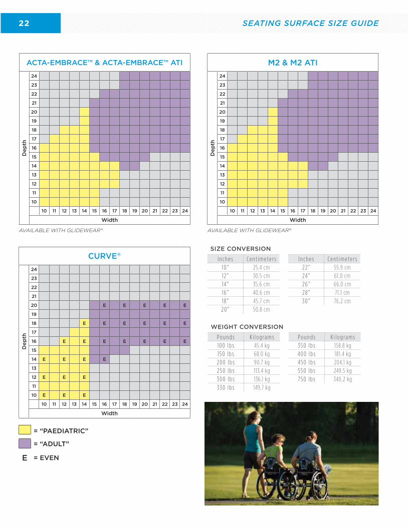
WEIGHT CONVERSION
P o u n d s K i l o g ra m s P o u n d s K i l o g ra m s1 0 0 l b s 45.4 kg 3 5 0 l b s 158.8 kg1 5 0 l b s 68.0 kg 4 0 0 l b s 181 .4 kg2 0 0 l b s 90.7 kg 4 5 0 l b s 204.1 kg2 5 0 l b s 113.4 kg 5 5 0 l b s 249.5 kg3 0 0 l b s 136.1 kg 7 5 0 l b s 340.2 kg3 3 0 l b s 149.7 kg
SEATING SURFACE SIZE GUIDE
ACTA-EMBRACE™ & ACTA-EMBRACE™ ATI
De
pth
24
23
22
21
20
19
18
17
16
15
14
13
12
11
10
10 11 12 13 14 15 16 17 18 19 20 21 22 23 24
Width
AVAILABLE WITH GLIDEWEAR®
M2 & M2 ATI
De
pth
24
23
22
21
20
19
18
17
16
15
14
13
12
11
10
10 11 12 13 14 15 16 17 18 19 20 21 22 23 24
Width
AVAILABLE WITH GLIDEWEAR®
CURVE®
De
pth
24
23
22
21
20 E E E E E
19
18 E E E E E E
17
16 E E E E E E E
15
14 E E E E
13
12 E E E
11
10 E E E
10 11 12 13 14 15 16 17 18 19 20 21 22 23 24
Width
= “ADULT”
E
= “PAEDIATRIC”
= EVEN
SIZE CONVERSION
I n c h e s C e n t i m e t e r s I n c h e s C e n t i m e t e r s1 0 ” 25.4 cm 2 2 ” 55.9 cm1 2 ” 30.5 cm 24 ” 61 .0 cm1 4 ” 35.6 cm 2 6 ” 66.0 cm1 6 ” 40.6 cm 2 8 ” 71 .1 cm1 8 ” 45.7 cm 3 0 ” 76.2 cm2 0 ” 50.8 cm
23
ADJUSTABLE TECHNOLOGY INSERT (ATI)
ACTA-EMBRACE™ ATI
Available with GlideWear® Technology. See pg. 20 for details.
*Zero Elevation with GlideWear® Pictured
SEATING SURFACES
24 SEATING SURFACES
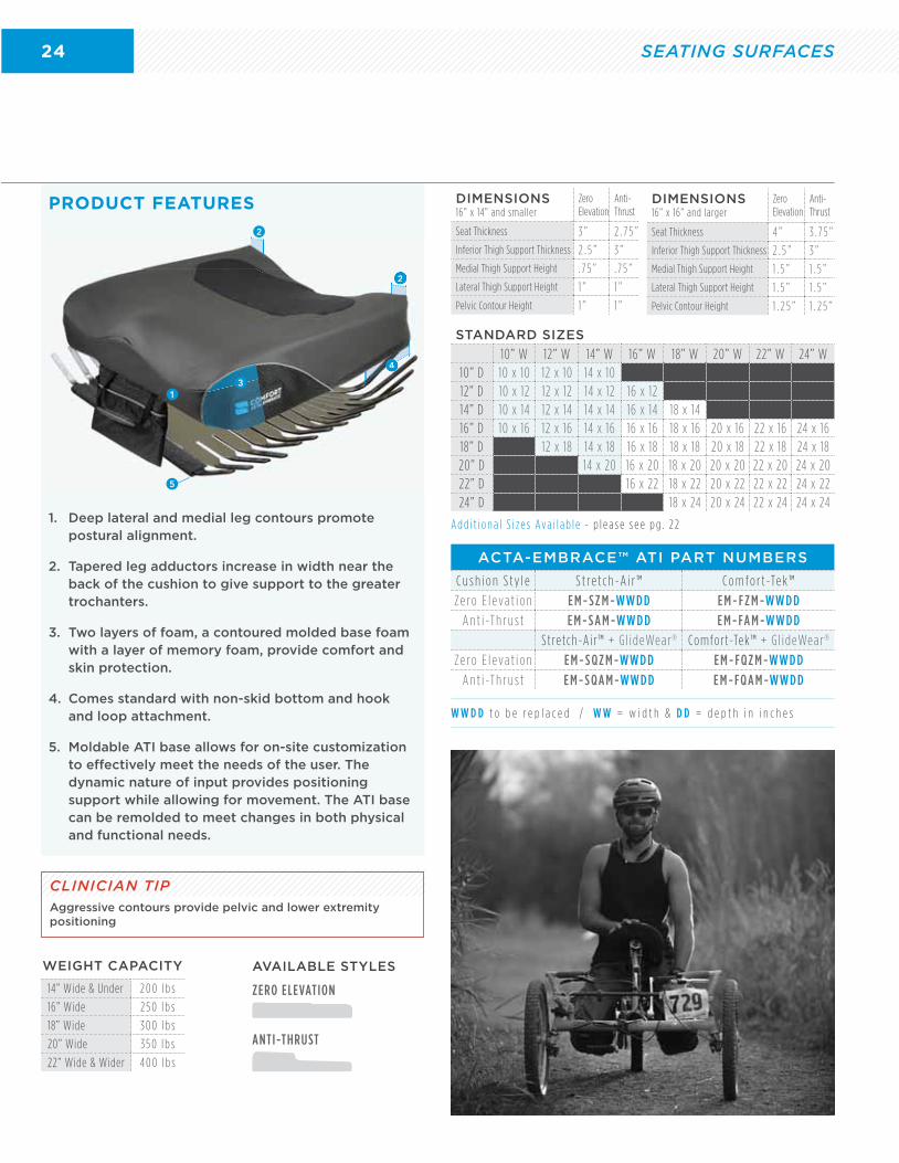
1. Deep lateral and medial leg contours promote postural alignment.
2. Tapered leg adductors increase in width near the back of the cushion to give support to the greater trochanters.
3. Two layers of foam, a contoured molded base foam with a layer of memory foam, provide comfort and skin protection.
4. Comes standard with non-skid bottom and hook and loop attachment.
5. Moldable ATI base allows for on-site customization to effectively meet the needs of the user. The dynamic nature of input provides positioning support while allowing for movement. The ATI base can be remolded to meet changes in both physical and functional needs.
PRODUCT FEATURES
STANDARD SIZES
10” W 12” W 14” W 16” W 18” W 20” W 22” W 24” W10” D 10 x 10 12 x 10 14 x 1012” D 10 x 12 12 x 12 14 x 12 16 x 1214” D 10 x 14 12 x 14 14 x 14 16 x 14 18 x 1416” D 10 x 16 12 x 16 14 x 16 16 x 16 18 x 16 20 x 16 22 x 16 24 x 1618” D 12 x 18 14 x 18 16 x 18 18 x 18 20 x 18 22 x 18 24 x 1820” D 14 x 20 16 x 20 18 x 20 20 x 20 22 x 20 24 x 2022” D 16 x 22 18 x 22 20 x 22 22 x 22 24 x 2224” D 18 x 24 20 x 24 22 x 24 24 x 24
ACTA-EMBRACE™ ATI PART NUMBERS
C u s h i o n S t y l e S t re t c h -A i r ™ C o m f o r t -Te k ™
Ze ro E l eva t i o n E M - S Z M -W W D D E M - F Z M -W W D D
A n t i -T h r u s t E M - S A M -W W D D E M - FA M -W W D D
Stretch-Ai r™ + G l ideWear ® Comfort-Tek™ + G l ideWear ®
Ze ro E l eva t i o n E M - S Q Z M -W W D D E M - F Q Z M -W W D D
A n t i -T h r u s t E M - S Q A M -W W D D E M - F Q A M -W W D D
WEIGHT CAPACITY
14” Wide & Under 2 0 0 l b s
16” Wide 2 5 0 l b s
18” Wide 3 0 0 l b s
20” Wide 3 5 0 l b s
22” Wide & Wider 4 0 0 l b s
DIMENSIONS16” x 14” and smaller
Zero Elevation
Anti-Thrust
Seat Thickness 3 ” 2 . 7 5 ”
Inferior Thigh Support Thickness 2 . 5 ” 3 ”
Medial Thigh Support Height . 7 5 ” . 7 5 ”
Lateral Thigh Support Height 1 ” 1 ”
Pelvic Contour Height 1 ” 1 ”
DIMENSIONS16” x 16” and larger
Zero Elevation
Anti-Thrust
Seat Thickness 4 ” 3 . 7 5 ”
Inferior Thigh Support Thickness 2 . 5 ” 3 ”
Medial Thigh Support Height 1 . 5 ” 1 . 5 ”
Lateral Thigh Support Height 1 . 5 ” 1 . 5 ”
Pelvic Contour Height 1 . 2 5 ” 1 . 2 5 ”
ZERO ELEVATION
ANTI-THRUST
AVAILABLE STYLES
A d d i t i o n a l S i z e s Ava i l a b l e - p l e a s e s e e p g . 2 2
W W D D t o b e r e p l a c e d / W W = w i d t h & D D = d e p t h i n i n c h e s
4
2
2
4
2
5
31
CLINICIAN TIPAggressive contours provide pelvic and lower extremity positioning
25
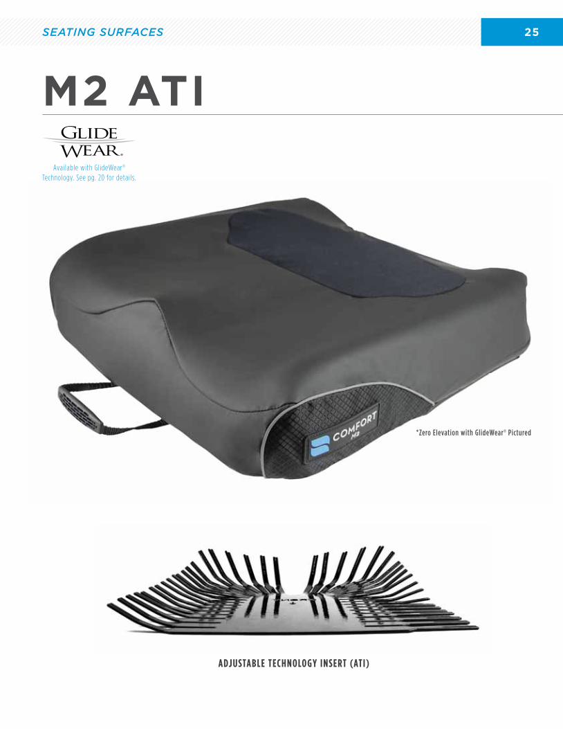
M2 ATI
Available with GlideWear® Technology. See pg. 20 for details.
*Zero Elevation with GlideWear® Pictured
ADJUSTABLE TECHNOLOGY INSERT (ATI)
SEATING SURFACES
26
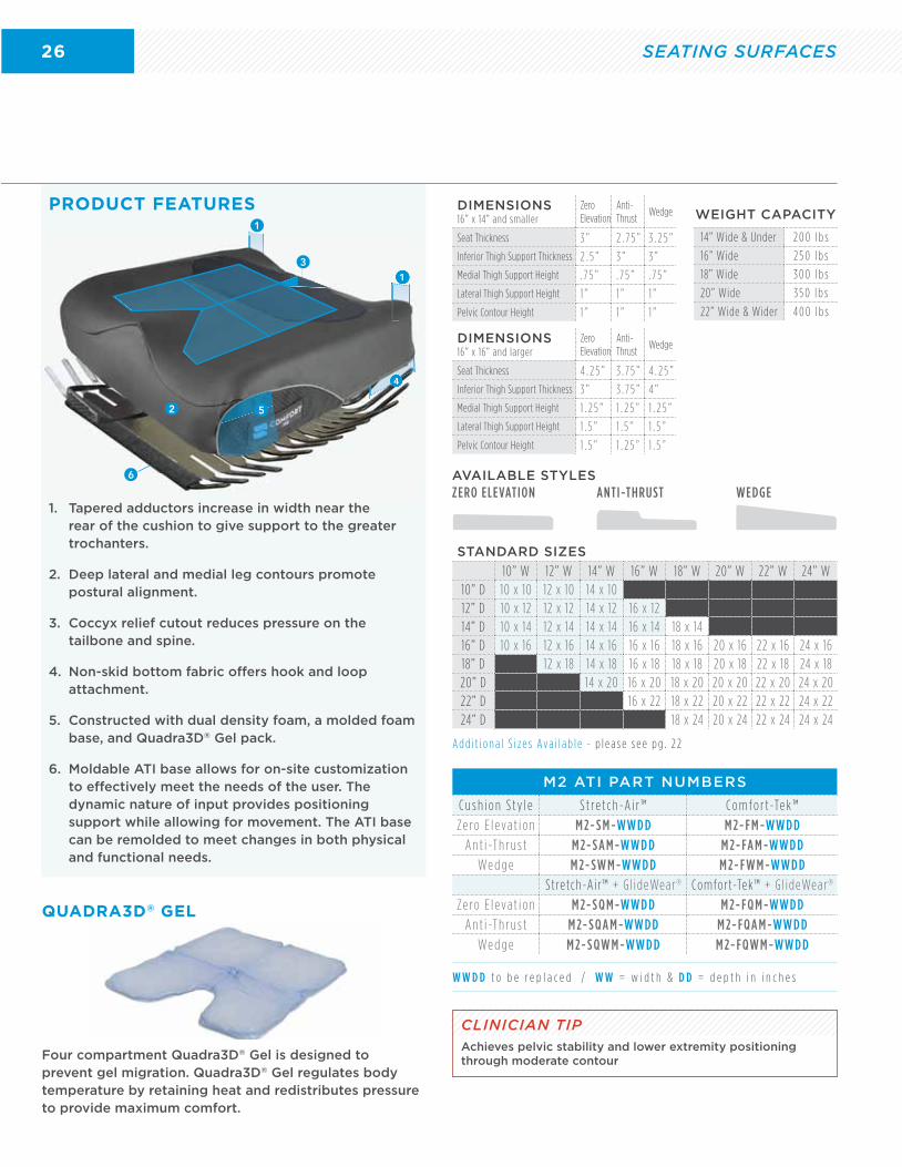
1. Tapered adductors increase in width near the rear of the cushion to give support to the greater trochanters.
2. Deep lateral and medial leg contours promote postural alignment.
3. Coccyx relief cutout reduces pressure on the tailbone and spine.
4. Non-skid bottom fabric offers hook and loop attachment.
5. Constructed with dual density foam, a molded foam base, and Quadra3D® Gel pack.
6. Moldable ATI base allows for on-site customization to effectively meet the needs of the user. The dynamic nature of input provides positioning support while allowing for movement. The ATI base can be remolded to meet changes in both physical and functional needs.
Four compartment Quadra3D® Gel is designed to prevent gel migration. Quadra3D® Gel regulates body temperature by retaining heat and redistributes pressure to provide maximum comfort.
PRODUCT FEATURES
QUADRA3D® GEL
ZERO ELEVATION ANTI-THRUST WEDGE
M2 ATI PART NUMBERS
C u s h i o n S t y l e S t re t c h -A i r ™ C o m f o r t -Te k ™
Ze ro E l eva t i o n M 2- S M -W W D D M 2- F M -W W D D
A n t i -T h r u s t M 2- S A M -W W D D M 2- FA M -W W D D
We d g e M 2- SW M -W W D D M 2- F W M -W W D D
Stretch-Ai r™ + G l ideWear ® Comfort-Tek™ + G l ideWear ®
Ze ro E l eva t i o n M 2- S Q M -W W D D M 2- F Q M -W W D D
A n t i -T h r u s t M 2- S Q A M -W W D D M 2- F Q A M -W W D D
We d g e M 2- S Q W M -W W D D M 2- F Q W M -W W D D
AVAILABLE STYLES
A d d i t i o n a l S i z e s Ava i l a b l e - p l e a s e s e e p g . 2 2
DIMENSIONS16” x 14” and smaller
Zero Elevation
Anti-Thrust
Wedge
Seat Thickness 3 ” 2 . 7 5 ” 3 . 2 5 ”
Inferior Thigh Support Thickness 2 . 5 ” 3 ” 3 ”
Medial Thigh Support Height . 7 5 ” . 7 5 ” . 7 5 ”
Lateral Thigh Support Height 1 ” 1 ” 1 ”
Pelvic Contour Height 1 ” 1 ” 1 ”
DIMENSIONS16” x 16” and larger
Zero Elevation
Anti-Thrust
Wedge
Seat Thickness 4 . 2 5 ” 3 . 7 5 ” 4 . 2 5 ”
Inferior Thigh Support Thickness 3 ” 3 . 7 5 ” 4 ”
Medial Thigh Support Height 1 . 2 5 ” 1 . 2 5 ” 1 . 2 5 ”
Lateral Thigh Support Height 1 . 5 ” 1 . 5 ” 1 . 5 ”
Pelvic Contour Height 1 . 5 ” 1 . 2 5 ” 1 . 5 ”
W W D D t o b e r e p l a c e d / W W = w i d t h & D D = d e p t h i n i n c h e s
4
1
1
4
1
2
3
6
5
STANDARD SIZES
10” W 12” W 14” W 16” W 18” W 20” W 22” W 24” W10” D 10 x 10 12 x 10 14 x 1012” D 10 x 12 12 x 12 14 x 12 16 x 1214” D 10 x 14 12 x 14 14 x 14 16 x 14 18 x 1416” D 10 x 16 12 x 16 14 x 16 16 x 16 18 x 16 20 x 16 22 x 16 24 x 1618” D 12 x 18 14 x 18 16 x 18 18 x 18 20 x 18 22 x 18 24 x 1820” D 14 x 20 16 x 20 18 x 20 20 x 20 22 x 20 24 x 2022” D 16 x 22 18 x 22 20 x 22 22 x 22 24 x 2224” D 18 x 24 20 x 24 22 x 24 24 x 24
CLINICIAN TIPAchieves pelvic stability and lower extremity positioning through moderate contour
WEIGHT CAPACITY
14” Wide & Under 2 0 0 l b s
16” Wide 2 5 0 l b s
18” Wide 3 0 0 l b s
20” Wide 3 5 0 l b s
22” Wide & Wider 4 0 0 l b s
SEATING SURFACES
27
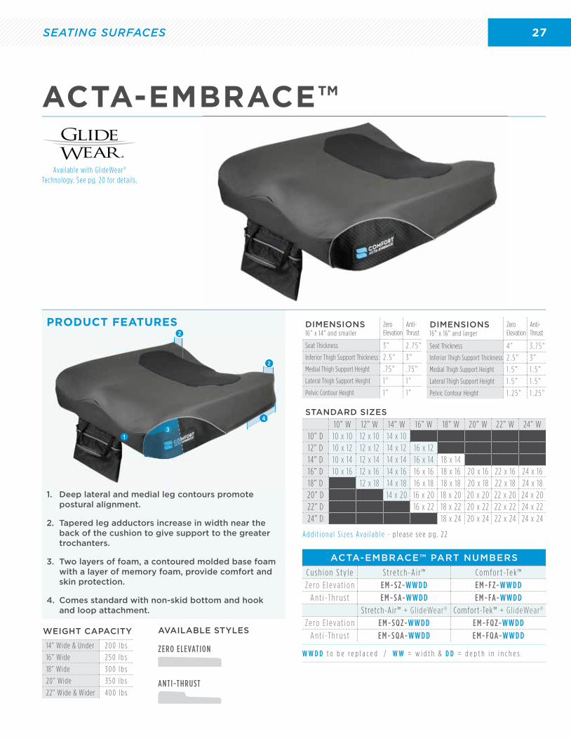
ACTA-EMBRACE™
1. Deep lateral and medial leg contours promote postural alignment.
2. Tapered leg adductors increase in width near the back of the cushion to give support to the greater trochanters.
3. Two layers of foam, a contoured molded base foam with a layer of memory foam, provide comfort and skin protection.
4. Comes standard with non-skid bottom and hook and loop attachment.
PRODUCT FEATURES
ZERO ELEVATION
ANTI-THRUST
ACTA-EMBRACE™ PART NUMBERS
C u s h i o n S t y l e S t re t c h -A i r ™ C o m f o r t -Te k ™
Ze ro E l eva t i o n E M - S Z-W W D D E M - F Z-W W D D
A n t i -T h r u s t E M - S A-W W D D E M - FA-W W D D
Stretch-Ai r™ + G l ideWear ® Comfort-Tek™ + G l ideWear ®
Ze ro E l eva t i o n E M - S Q Z-W W D D E M - F Q Z-W W D D
A n t i -T h r u s t E M - S Q A-W W D D E M - F Q A-W W D DAVAILABLE STYLES
W W D D t o b e r e p l a c e d / W W = w i d t h & D D = d e p t h i n i n c h e s
Available with GlideWear® Technology. See pg. 20 for details.
A d d i t i o n a l S i z e s Ava i l a b l e - p l e a s e s e e p g . 2 2
STANDARD SIZES
10” W 12” W 14” W 16” W 18” W 20” W 22” W 24” W10” D 10 x 10 12 x 10 14 x 1012” D 10 x 12 12 x 12 14 x 12 16 x 1214” D 10 x 14 12 x 14 14 x 14 16 x 14 18 x 1416” D 10 x 16 12 x 16 14 x 16 16 x 16 18 x 16 20 x 16 22 x 16 24 x 1618” D 12 x 18 14 x 18 16 x 18 18 x 18 20 x 18 22 x 18 24 x 1820” D 14 x 20 16 x 20 18 x 20 20 x 20 22 x 20 24 x 2022” D 16 x 22 18 x 22 20 x 22 22 x 22 24 x 2224” D 18 x 24 20 x 24 22 x 24 24 x 24
4
2
2
4
2
31
DIMENSIONS16” x 14” and smaller
Zero Elevation
Anti-Thrust
Seat Thickness 3 ” 2 . 7 5 ”
Inferior Thigh Support Thickness 2 . 5 ” 3 ”
Medial Thigh Support Height . 7 5 ” . 7 5 ”
Lateral Thigh Support Height 1 ” 1 ”
Pelvic Contour Height 1 ” 1 ”
DIMENSIONS16” x 16” and larger
Zero Elevation
Anti-Thrust
Seat Thickness 4 ” 3 . 7 5 ”
Inferior Thigh Support Thickness 2 . 5 ” 3 ”
Medial Thigh Support Height 1 . 5 ” 1 . 5 ”
Lateral Thigh Support Height 1 . 5 ” 1 . 5 ”
Pelvic Contour Height 1 . 2 5 ” 1 . 2 5 ”
WEIGHT CAPACITY
14” Wide & Under 2 0 0 l b s
16” Wide 2 5 0 l b s
18” Wide 3 0 0 l b s
20” Wide 3 5 0 l b s
22” Wide & Wider 4 0 0 l b s
SEATING SURFACES
28
QUADRA3D® GELS e e p g . 2 1 f o r d e t a i l s .
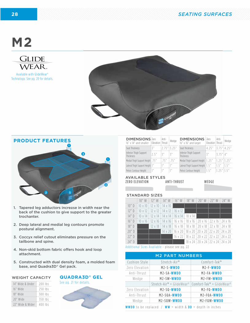
M2
1. Tapered leg adductors increase in width near the back of the cushion to give support to the greater trochanter.
2. Deep lateral and medial leg contours promote postural alignment.
3. Coccyx relief cutout eliminates pressure on the tailbone and spine.
4. Non-skid bottom fabric offers hook and loop attachment.
5. Constructed with dual density foam, a molded foam base, and Quadra3D® Gel pack.
PRODUCT FEATURES
W W D D t o b e r e p l a c e d / W W = w i d t h & D D = d e p t h i n i n c h e s
ZERO ELEVATION ANTI-THRUST WEDGE
M2 PART NUMBERS
C u s h i o n S t y l e S t re t c h -A i r ™ C o m f o r t -Te k ™
Ze ro E l eva t i o n M 2- S -W W D D M 2- F -W W D D
A n t i -T h r u s t M 2- S A-W W D D M 2- FA-W W D D
We d g e M 2- SW-W W D D M 2- F W-W W D D
Stretch-Ai r™ + G l ideWear ® Comfort-Tek™ + G l ideWear ®
Ze ro E l eva t i o n M 2- S Q -W W D D M 2- F Q -W W D D
A n t i -T h r u s t M 2- S Q A-W W D D M 2- F Q A-W W D D
We d g e M 2- S Q W-W W D D M 2- F Q W-W W D D
AVAILABLE STYLES
Available with GlideWear® Technology. See pg. 20 for details.
A d d i t i o n a l S i z e s Ava i l a b l e - p l e a s e s e e p g . 2 2
STANDARD SIZES
10” W 12” W 14” W 16” W 18” W 20” W 22” W 24” W10” D 10 x 10 12 x 10 14 x 1012” D 10 x 12 12 x 12 14 x 12 16 x 1214” D 10 x 14 12 x 14 14 x 14 16 x 14 18 x 1416” D 10 x 16 12 x 16 14 x 16 16 x 16 18 x 16 20 x 16 22 x 16 24 x 1618” D 12 x 18 14 x 18 16 x 18 18 x 18 20 x 18 22 x 18 24 x 1820” D 14 x 20 16 x 20 18 x 20 20 x 20 22 x 20 24 x 2022” D 16 x 22 18 x 22 20 x 22 22 x 22 24 x 2224” D 18 x 24 20 x 24 22 x 24 24 x 24
1
1
1. Tapered leg adductors increase in width near the
1
1
4
2
3
5
DIMENSIONS16” x 14” and smaller
Zero Elevation
Anti-Thrust
Wedge
Seat Thickness 3 ” 2 . 7 5 ” 3 . 2 5 ”Inferior Thigh Support Thickness 2 . 5 ” 3 ” 3 ”
Medial Thigh Support Height . 7 5 ” . 7 5 ” . 7 5 ”
Lateral Thigh Support Height 1 ” 1 ” 1 ”
Pelvic Contour Height 1 ” 1 ” 1 ”
DIMENSIONS16” x 16” and larger
Zero Elevation
Anti-Thrust
Wedge
Seat Thickness 4 . 2 5 ” 3 . 7 5 ” 4 . 2 5 ”Inferior Thigh Support Thickness 3 ” 3 . 7 5 ” 4 ”
Medial Thigh Support Height 1 . 2 5 ” 1 . 2 5 ” 1 . 2 5 ”
Lateral Thigh Support Height 1 . 5 ” 1 . 5 ” 1 . 5 ”
Pelvic Contour Height 1 . 5 ” 1 . 2 5 ” 1 . 5 ”
WEIGHT CAPACITY
14” Wide & Under 2 0 0 l b s
16” Wide 2 5 0 l b s
18” Wide 3 0 0 l b s
20” Wide 3 5 0 l b s
22” Wide & Wider 4 0 0 l b s
SEATING SURFACES

29
CURVE®
PRODUCT FEATURES
1. Mild anti-thrust shelf promotes postural stability and helps prevent forward migration.
2. Medial thigh separator promotes postural alignment.
3. High density, molded foam increases surface area reducing potential peak pressure areas.
4. Non-skid flat bottom fabric offers hook and loop attachment.
A d d i t i o n a l S i z e s Ava i l a b l e - p l e a s e s e e p g . 2 2
CURVE PART NUMBERS
C ove r S t y l e S t re t c h -A i r ™ C o m f o r t -Te k ™
S t a n d a rd C U - SV-W W D D C U - F V-W W D D
2
3
1
4
W W D D t o b e r e p l a c e d / W W = w i d t h & D D = d e p t h i n i n c h e s
STANDARD SIZES
1 6 ” W 1 8 ” W 2 0 ” W 2 2 ” W 24 ” W1 4 ” D 1 6 x 1 41 6 ” D 1 6 x 1 6 1 8 x 1 6 2 0 x 1 6 2 2 x 1 6 24 x 1 61 8 ” D 1 6 x 1 8 1 8 x 1 8 2 0 x 1 8 2 2 x 1 8 24 x 1 82 0 ” D 1 6 x 2 0 1 8 x 2 0 2 0 x 2 0 2 2 x 2 0 24 x 2 0
PEDIATRIC SIZES
1 0 ” W 1 2 ” W 1 4 ” W1 0 ” D 1 0 x 1 0 1 2 x 1 0 1 4 x 1 01 2 ” D 1 0 x 1 2 1 2 x 1 2 1 4 x 1 21 4 ” D 1 0 x 1 4 1 2 x 1 4 1 4 x 1 41 6 ” D 1 2 x 1 6 1 4 x 1 61 8 ” D 1 4 x 1 8
CLINICIAN TIPTop general use choice for pressure redistribution and stability
WEIGHT CAPACITY
12” Wide & Under 1 0 0 l b s
14” Wide 1 5 0 l b s
16” Wide 2 5 0 l b s
18” Wide 3 0 0 l b s
20” Wide 3 5 0 l b s
22” Wide & Wider 4 0 0 l b s
DIMENSIONS
Seat Thickness 3 ”
Inferior Thigh Support Thickness 2 . 2 5 ”
Medial Thigh Support Thickness 1 ”
Lateral Thigh Support Height 1 ”
Pelvic Contour Height 1 ”
SEATING SURFACES

30
LATERAL PELVIC/THIGH SUPPORTS
PRODUCT FEATURES• 10 pad sizes available in each Zero Elevation and
Anti-Thrust.
• Comfort-Tek, Stretch-Air and GlideWear cover options.
• Compatible on virtually any power or manual wheelchair.
• All new Telescoping Taper (TT) series and GT series.
• Fixed or removable with high visibility release lever.
• Extra links (GT) and long extension arm (TT) allow for greater medial reach when needed.
RIGID INSERT
S i z e s Ava i l a b l e : 1 0 ” W x 1 0 ” D - 2 8 ” W x 2 2 ” D
PRODUCT FEATURES• Decreases the “hammock” effect in outstretched
wheelchair upholstery and provides extra support for heavier users.
• Designed to fit all Comfort Company cushions.
• Made of ABS plastic.
• Comes in 3/16” thickness.
RIGID INSERT PART NUMBERS
R I D W W D D
W W D D t o b e r e p l a c e d / W W = w i d t h & D D = d e p t h i n i n c h e s
REMOVABLE SOLID SEAT PAN
PRODUCT FEATURES• Includes a slotted aluminum pan and attaching
hardware for 7/8” or 1” tubing.
• Comes with two different cross bars to accommodate various wheelchair frame types.
• Lateral thigh supports can be easily attached.
S i z e s Ava i l a b l e : 1 0 ” W x 1 0 ” D - 2 8 ” W x 2 2 ” D
REMOVABLE SOLID SEAT PAN PART NUMBERS
R S S P -1 -W W D D
W W D D t o b e r e p l a c e d / W W = w i d t h & D D = d e p t h i n i n c h e s
GT Series (Gear Tooth) Slot Mounting
Zero Elevation10 Sizes
3 Cover Options
Anti-Thrust10 Sizes
3 Cover Options
TT Series (Telescoping Taper) Power and Slot Mounting
PLEASE CONTACT CUSTOMER SERVICE, VISIT OUR WEBSITE, OR SEE THE ORDER FORMS FOR ALL THESE PART NUMBERS.
HARDWAREAdjustable release lever position for removable style hardware
fits user needs and preference.
PADS
SEATING SURFACE ACCESSORIES
31
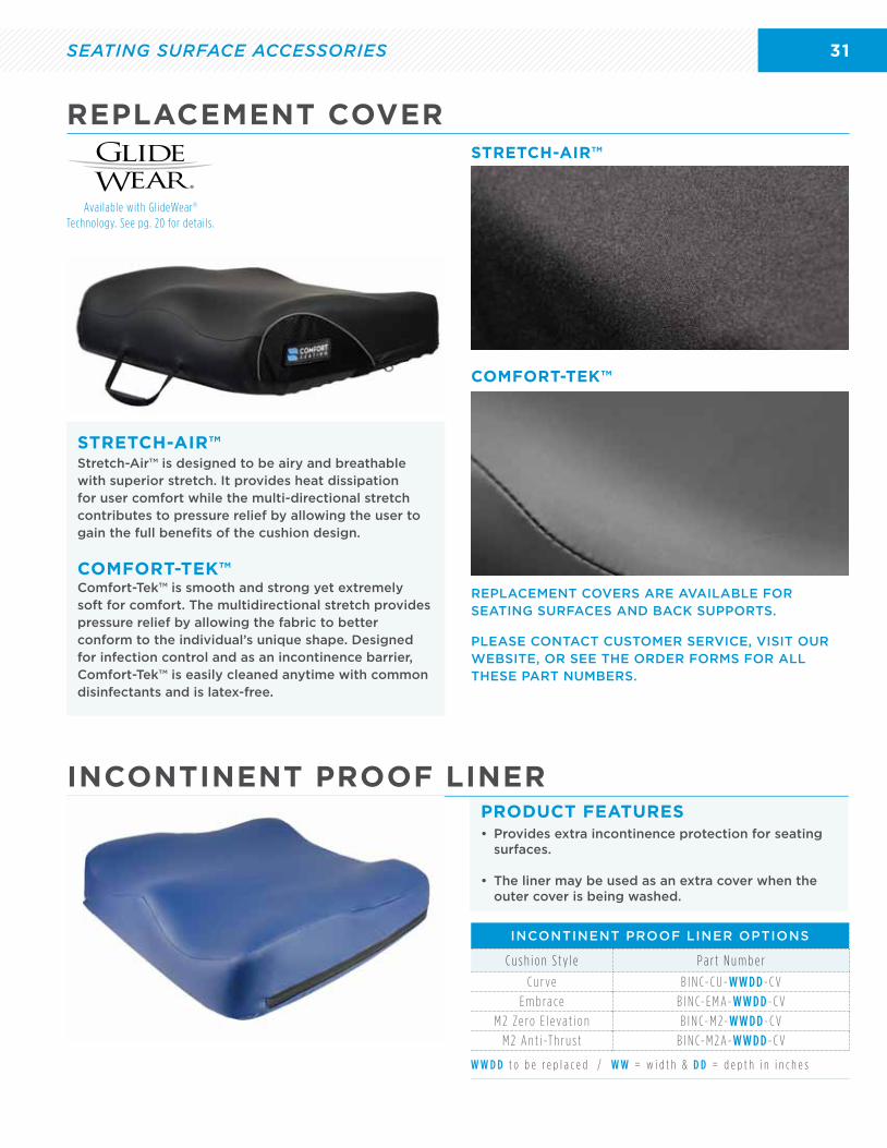
REPLACEMENT COVER
INCONTINENT PROOF LINERPRODUCT FEATURES
STRETCH-AIR™
STRETCH-AIR™
COMFORT-TEK™
COMFORT-TEK™
Stretch-Air™ is designed to be airy and breathable with superior stretch. It provides heat dissipation for user comfort while the multi-directional stretch contributes to pressure relief by allowing the user to gain the full benefits of the cushion design.
Comfort-Tek™ is smooth and strong yet extremely soft for comfort. The multidirectional stretch provides pressure relief by allowing the fabric to better conform to the individual’s unique shape. Designed for infection control and as an incontinence barrier, Comfort-Tek™ is easily cleaned anytime with common disinfectants and is latex-free.
REPLACEMENT COVERS ARE AVAILABLE FOR SEATING SURFACES AND BACK SUPPORTS.
PLEASE CONTACT CUSTOMER SERVICE, VISIT OUR WEBSITE, OR SEE THE ORDER FORMS FOR ALL THESE PART NUMBERS.
W W D D t o b e r e p l a c e d / W W = w i d t h & D D = d e p t h i n i n c h e s
• Provides extra incontinence protection for seating surfaces.
• The liner may be used as an extra cover when the outer cover is being washed.
Available with GlideWear® Technology. See pg. 20 for details.
INCONTINENT PROOF LINER OPTIONS
C u s h i o n S t y l e P a r t N u m b e r
C u r ve B I N C- C U - W W D D - C V
E m b ra c e B I N C- E M A- W W D D - C V
M 2 Ze ro E l eva t i o n B I N C- M 2- W W D D - C V
M 2 A n t i -T h r u s t B I N C- M 2 A- W W D D - C V
SEATING SURFACE ACCESSORIES
32 ACCESSORIES
ACCESSORIESOften overlooked, proper support accessories are a critical component to an effective
seating & positioning system. Comfort Company specializes in providing unique,
innovative accessories to ensure effective foot, arm, & amputee support.
33
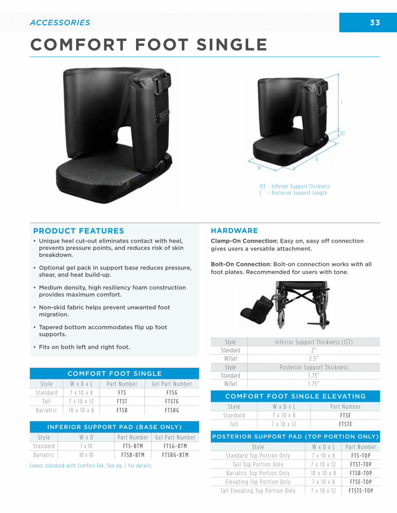
• Unique heel cut-out eliminates contact with heel, prevents pressure points, and reduces risk of skin breakdown.
• Optional gel pack in support base reduces pressure, shear, and heat build-up.
• Medium density, high resiliency foam construction provides maximum comfort.
• Non-skid fabric helps prevent unwanted foot migration.
• Tapered bottom accommodates flip up foot supports.
• Fits on both left and right foot.
PRODUCT FEATURES
COMFORT FOOT SINGLE
S t y l e W x D x L P a r t N u m b e r G e l P a r t N u m b e r
S t a n d a rd 7 x 1 0 x 8 F T S F T S G
Ta l l 7 x 1 0 x 1 2 F T S T F T S TG
B a r i a t r i c 1 0 x 1 0 x 8 F T S B F T S B G
POSTERIOR SUPPORT PAD (TOP PORTION ONLY)
S t y l e W x D x L P a r t N u m b e r
S t a n d a rd To p P o r t i o n O n l y 7 x 1 0 x 8 F T S -TO P
Ta l l To p P o r t i o n O n l y 7 x 1 0 x 1 2 F T S T-TO P
B a r i a t r i c To p P o r t i o n O n l y 1 0 x 1 0 x 8 F T S B -TO P
E l eva t i n g To p P o r t i o n O n l y 7 x 1 0 x 8 F T S E -TO P
Ta l l E l eva t i n g To p P o r t i o n O n l y 7 x 1 0 x 1 2 F T S T E -TO P
COMFORT FOOT SINGLE ELEVATING
S t y l e W x D x L P a r t N u m b e r
S t a n d a rd 7 x 1 0 x 8 F T S E
Ta l l 7 x 1 0 x 1 2 F T S T EINFERIOR SUPPORT PAD (BASE ONLY)
S t y l e W x D P a r t N u m b e r G e l P a r t N u m b e r
S t a n d a rd 7 x 10 F T S - B T M F T S G - B T M
B a r i a t r i c 10 x 10 F T S B - B T M F T S B G - B T M
C o m e s s t a n d a rd w i t h C o m f o r t -Te k . S e e p g . 1 f o r d e t a i l s .
Clamp-On Connection: Easy on, easy off connection gives users a versatile attachment.
Bolt-On Connection: Bolt-on connection works with all foot plates. Recommended for users with tone.
HARDWARE
COMFORT FOOT SINGLE
I S T - I n f e r i o r S u p p o r t T h i c k n e s sL - P o s t e r i o r S u p p o r t L e n g t h
Style I n f e r i o r S u p p o r t T h i c k n e s s ( I S T )Standard 2 ”
W/Gel 2 . 5 ”
W
D
L
IST
Style P o s t e r i o r S u p p o r t T h i c k n e s sStandard 1 . 7 5 ”
W/Gel 1 . 7 5 ”
ACCESSORIES
34 ACCESSORIES
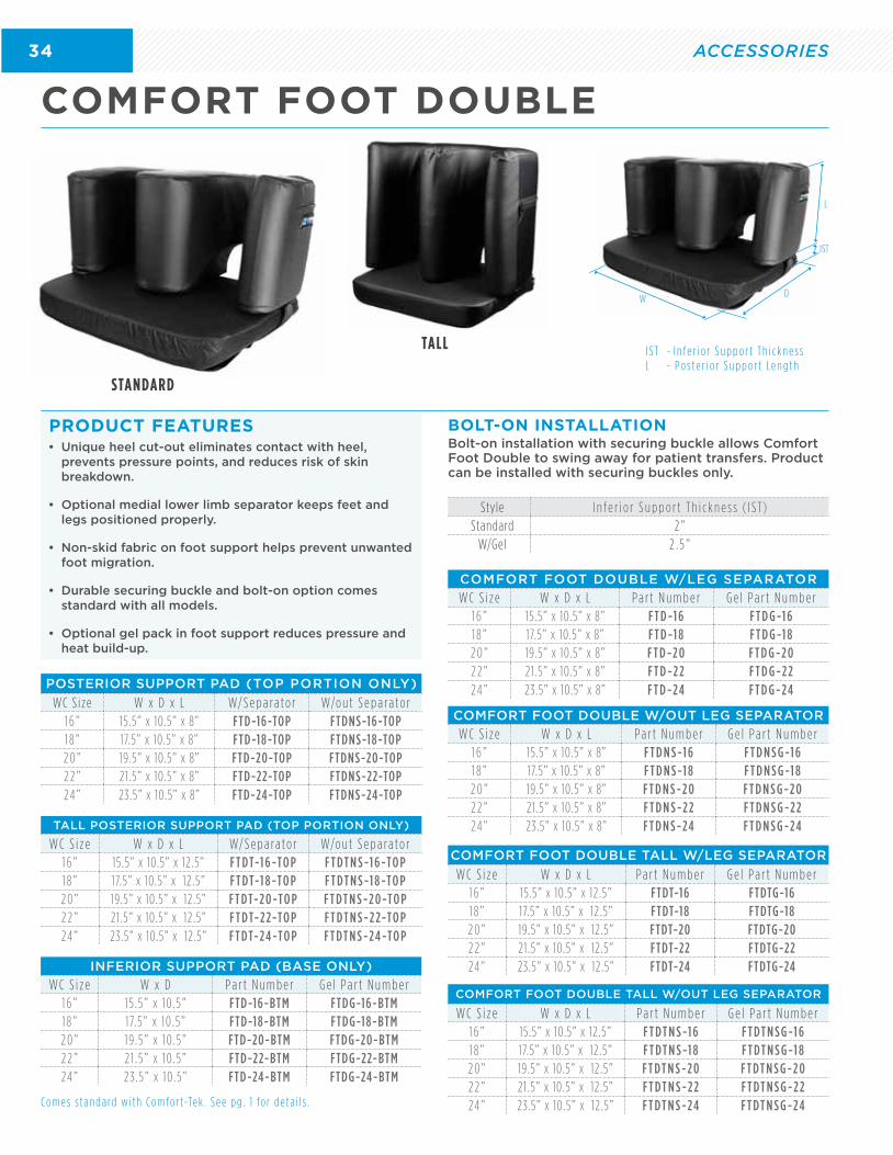
COMFORT FOOT DOUBLE
STANDARD
TALL
• Unique heel cut-out eliminates contact with heel, prevents pressure points, and reduces risk of skin breakdown.
• Optional medial lower limb separator keeps feet and legs positioned properly.
• Non-skid fabric on foot support helps prevent unwanted foot migration.
• Durable securing buckle and bolt-on option comes standard with all models.
• Optional gel pack in foot support reduces pressure and heat build-up.
PRODUCT FEATURES
Co m e s s t a n d a rd w i t h Co m fo r t-Te k . S e e p g . 1 fo r d e t a i l s .
Bolt-on installation with securing buckle allows Comfort Foot Double to swing away for patient transfers. Product can be installed with securing buckles only.
BOLT-ON INSTALLATION
COMFORT FOOT DOUBLE W/LEG SEPARATOR
W C S i z e W x D x L P a r t N u m b e r G e l P a r t N u m b e r1 6 ” 15.5” x 10.5” x 8” F T D -1 6 F T D G -1 61 8 ” 17.5” x 10.5” x 8” F T D -1 8 F T D G -1 82 0 ” 19.5” x 10.5” x 8” F T D -2 0 F T D G -2 02 2 ” 21 .5” x 10.5” x 8” F T D -2 2 F T D G -2 224 ” 23.5” x 10.5” x 8” F T D -2 4 F T D G -2 4
INFERIOR SUPPORT PAD (BASE ONLY)
W C S i z e W x D P a r t N u m b e r G e l P a r t N u m b e r1 6 ” 15 .5” x 10 .5” FTD-16-BTM FTDG-16-BTM1 8 ” 17.5” x 10 .5” FTD-18-BTM FTDG-18-BTM2 0 ” 19 .5” x 10 .5” FTD-20-BTM FTDG-20-BTM2 2 ” 21 .5” x 10 .5” FTD-22-BTM FTDG-22-BTM24 ” 23 .5” x 10 .5” FTD-24-BTM FTDG-24-BTM
POSTERIOR SUPPORT PAD (TOP PORTION ONLY)
WC S ize W x D x L W/ S e p a ra t o r W/o u t S e p a ra t o r1 6 ” 15.5” x 10.5” x 8” FTD-16-TOP FTDNS-16-TOP1 8 ” 17.5” x 10.5” x 8” FTD-18-TOP FTDNS-18-TOP2 0 ” 19.5” x 10.5” x 8” FTD-20-TOP FTDNS-20-TOP2 2 ” 21 .5” x 10.5” x 8” FTD-22-TOP FTDNS-22-TOP24 ” 23.5” x 10.5” x 8” FTD-24-TOP FTDNS-24-TOP
COMFORT FOOT DOUBLE W/OUT LEG SEPARATOR
W C S i z e W x D x L P a r t N u m b e r G e l P a r t N u m b e r1 6 ” 15.5” x 10.5” x 8” F T D N S -1 6 F T D N S G -1 61 8 ” 17.5” x 10.5” x 8” F T D N S -1 8 F T D N S G -1 82 0 ” 19.5” x 10.5” x 8” F T D N S -2 0 F T D N S G -2 02 2 ” 21 .5” x 10.5” x 8” F T D N S -2 2 F T D N S G -2 224 ” 23.5” x 10.5” x 8” F T D N S -2 4 F T D N S G -2 4
Style I n f e r i o r S u p p o r t T h i c k n e s s ( I S T )Standard 2 ”
W/Gel 2 . 5 ”
I S T - I n f e r i o r S u p p o r t T h i c k n e s sL - P o s t e r i o r S u p p o r t L e n g t h
W D
IST
L
COMFORT FOOT DOUBLE TALL W/LEG SEPARATOR
W C S i z e W x D x L P a r t N u m b e r G e l P a r t N u m b e r1 6 ” 15.5” x 10.5” x 12 .5” FTDT-16 FTDTG-161 8 ” 17.5” x 10.5” x 12 .5” FTDT-18 FTDTG-182 0 ” 19.5” x 10.5” x 12 .5” FTDT-20 FTDTG-202 2 ” 21 .5” x 10.5” x 12 .5” FTDT-22 FTDTG-2224 ” 23.5” x 10.5” x 12 .5” FTDT-24 FTDTG-24
TALL POSTERIOR SUPPORT PAD (TOP PORTION ONLY)
W C S i z e W x D x L W/ S e p a ra t o r W/o u t S e p a ra t o r1 6 ” 15.5” x 10.5” x 12 .5” F T DT-1 6 -TO P F T DT N S -1 6 -TO P1 8 ” 17.5” x 10.5” x 12 .5” F T DT-1 8 -TO P F T DT N S -1 8 -TO P2 0 ” 19.5” x 10.5” x 12 .5” F T DT-2 0 -TO P F T DT N S -2 0 -TO P2 2 ” 21 .5” x 10.5” x 12 .5” F T DT-2 2-TO P F T DT N S -2 2-TO P24 ” 23.5” x 10.5” x 12 .5” F T DT-2 4 -TO P F T DT N S -2 4 -TO P
COMFORT FOOT DOUBLE TALL W/OUT LEG SEPARATOR
W C S i z e W x D x L P a r t N u m b e r G e l P a r t N u m b e r1 6 ” 15.5” x 10.5” x 12 .5” F T DT N S -1 6 F T DT N S G -1 61 8 ” 17.5” x 10.5” x 12 .5” F T DT N S -1 8 F T DT N S G -1 82 0 ” 19.5” x 10.5” x 12 .5” F T DT N S -2 0 F T DT N S G -2 02 2 ” 21 .5” x 10.5” x 12 .5” F T DT N S -2 2 F T DT N S G -2 224 ” 23.5” x 10.5” x 12 .5” F T DT N S -2 4 F T DT N S G -2 4
35
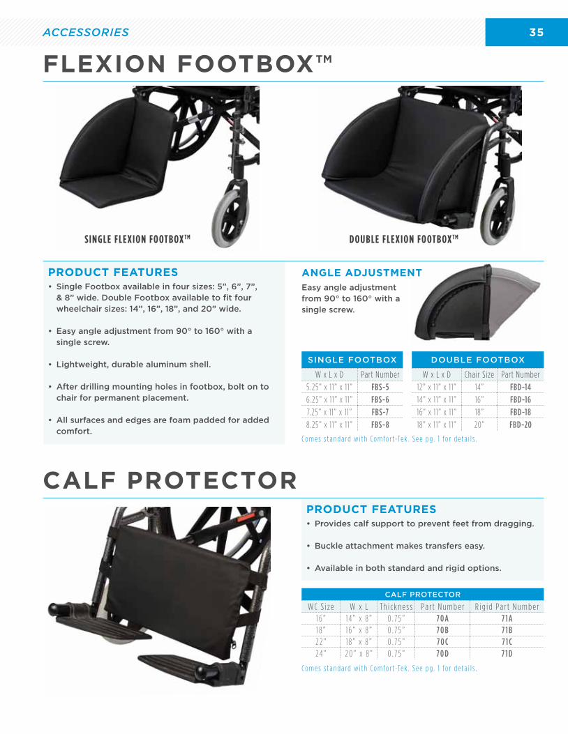
• Single Footbox available in four sizes: 5”, 6”, 7”, & 8” wide. Double Footbox available to fit four wheelchair sizes: 14”, 16”, 18”, and 20” wide.
• Easy angle adjustment from 90° to 160° with a single screw.
• Lightweight, durable aluminum shell.
• After drilling mounting holes in footbox, bolt on to chair for permanent placement.
• All surfaces and edges are foam padded for added comfort.
• Provides calf support to prevent feet from dragging.
• Buckle attachment makes transfers easy.
• Available in both standard and rigid options.
PRODUCT FEATURES
PRODUCT FEATURES
SINGLE FOOTBOX
W x L x D Part Number
5.25” x 11” x 11” FBS-5
6.25” x 11” x 11” FBS-6
7.25” x 11” x 11” FBS-7
8.25” x 11” x 11” FBS-8
DOUBLE FOOTBOX
W x L x D Chair Size Part Number
12” x 11” x 11” 14” FBD-14
14” x 11” x 11” 16” FBD-16
16” x 11” x 11” 18” FBD-18
18” x 11” x 11” 20” FBD-20
C o m e s s t a n d a rd w i t h C o m f o r t -Te k . S e e p g . 1 f o r d e t a i l s .
C o m e s s t a n d a rd w i t h C o m f o r t -Te k . S e e p g . 1 f o r d e t a i l s .
Easy angle adjustment from 90° to 160° with a single screw.
ANGLE ADJUSTMENT
FLEXION FOOTBOX™
CALF PROTECTOR
NT
CALF PROTECTOR
W C S i z e W x L T h i c k n e s s P a r t N u m b e r R i g i d P a r t N u m b e r1 6 ” 1 4 ” x 8 ” 0 . 7 5 ” 7 0 A 7 1 A1 8 ” 1 6 ” x 8 ” 0 . 7 5 ” 7 0 B 7 1 B2 2 ” 1 8 ” x 8 ” 0 . 7 5 ” 7 0 C 7 1 C24 ” 2 0 ” x 8 ” 0 . 7 5 ” 7 0 D 7 1 D
SINGLE FLEXION FOOTBOX TM DOUBLE FLEXION FOOTBOX TM
ACCESSORIES
36 ACCESSORIES
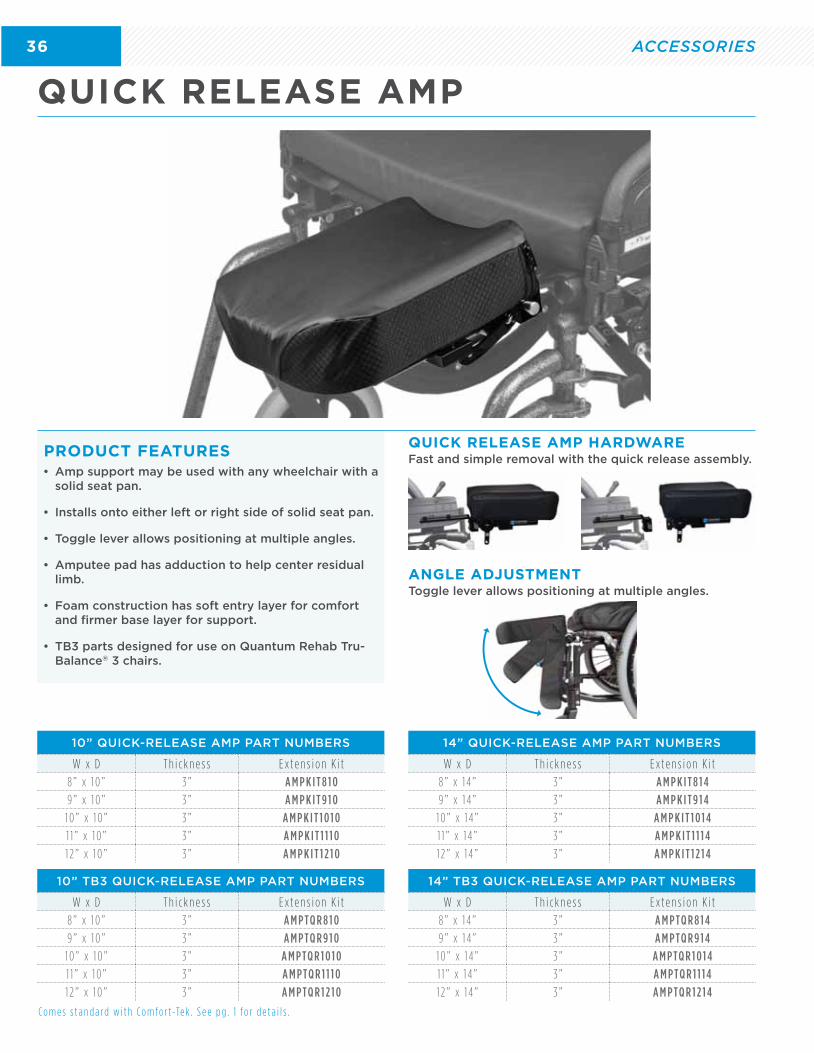
QUICK RELEASE AMP
• Amp support may be used with any wheelchair with a solid seat pan.
• Installs onto either left or right side of solid seat pan.
• Toggle lever allows positioning at multiple angles.
• Amputee pad has adduction to help center residual limb.
• Foam construction has soft entry layer for comfort and firmer base layer for support.
• TB3 parts designed for use on Quantum Rehab Tru-Balance® 3 chairs.
PRODUCT FEATURES
C o m e s s t a n d a rd w i t h C o m f o r t -Te k . S e e p g . 1 f o r d e t a i l s .
Fast and simple removal with the quick release assembly.
Toggle lever allows positioning at multiple angles.
QUICK RELEASE AMP HARDWARE
ANGLE ADJUSTMENT
10” QUICK-RELEASE AMP PART NUMBERS
W x D T h i c k n e s s E x t e n s i o n K i t
8 ” x 1 0 ” 3 ” A M P K I T 8 1 0
9 ” x 1 0 ” 3 ” A M P K I T 9 1 0
1 0 ” x 1 0 ” 3 ” A M P K I T 1 0 1 0
1 1 ” x 1 0 ” 3 ” A M P K I T 1 1 1 0
1 2 ” x 1 0 ” 3 ” A M P K I T 1 2 1 0
14” QUICK-RELEASE AMP PART NUMBERS
W x D T h i c k n e s s E x t e n s i o n K i t
8 ” x 1 4 ” 3 ” A M P K I T 8 1 4
9 ” x 1 4 ” 3 ” A M P K I T 9 1 4
1 0 ” x 1 4 ” 3 ” A M P K I T 1 0 1 4
1 1 ” x 1 4 ” 3 ” A M P K I T 1 1 1 4
1 2 ” x 1 4 ” 3 ” A M P K I T 1 2 1 4
10” TB3 QUICK-RELEASE AMP PART NUMBERS
W x D T h i c k n e s s E x t e n s i o n K i t
8 ” x 1 0 ” 3 ” A M P TQ R 8 1 0
9 ” x 1 0 ” 3 ” A M P TQ R 9 1 0
1 0 ” x 1 0 ” 3 ” A M P TQ R 1 0 1 0
1 1 ” x 1 0 ” 3 ” A M P TQ R 1 1 1 0
1 2 ” x 1 0 ” 3 ” A M P TQ R 1 2 1 0
14” TB3 QUICK-RELEASE AMP PART NUMBERS
W x D T h i c k n e s s E x t e n s i o n K i t
8 ” x 1 4 ” 3 ” A M P TQ R 8 1 4
9 ” x 1 4 ” 3 ” A M P TQ R 9 1 4
1 0 ” x 1 4 ” 3 ” A M P TQ R 1 0 1 4
1 1 ” x 1 4 ” 3 ” A M P TQ R 1 1 1 4
1 2 ” x 1 4 ” 3 ” A M P TQ R 1 2 1 4
37
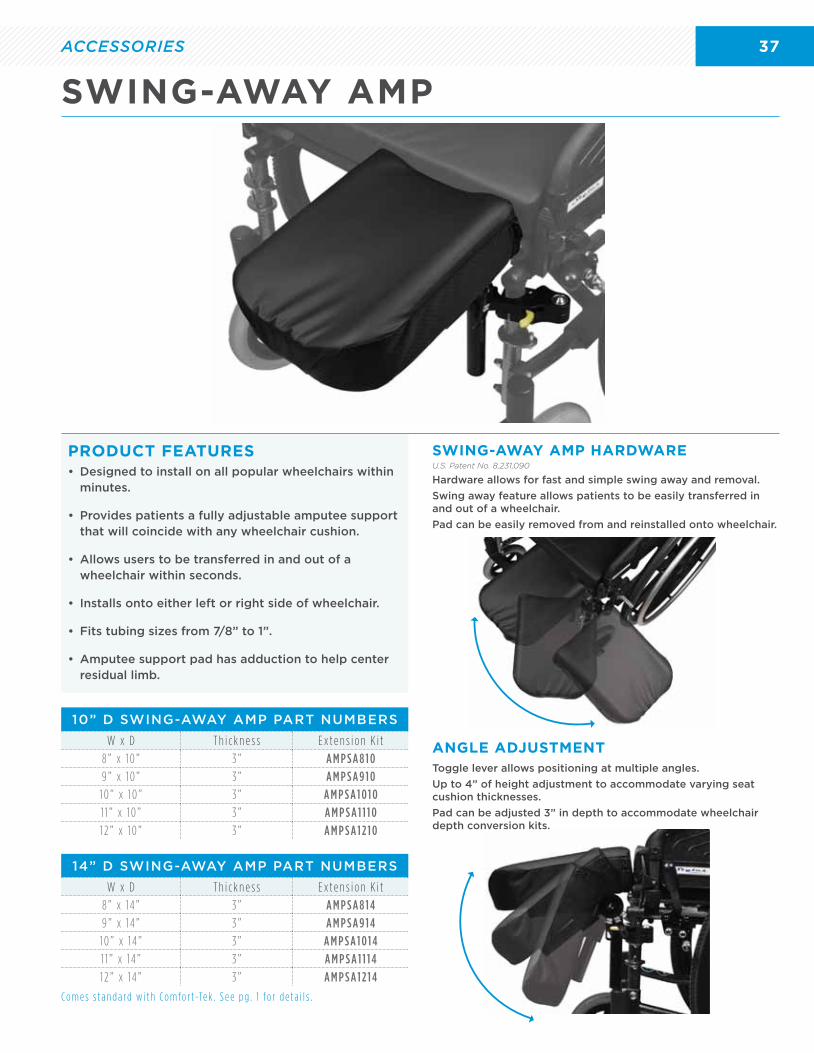
• Designed to install on all popular wheelchairs within minutes.
• Provides patients a fully adjustable amputee support that will coincide with any wheelchair cushion.
• Allows users to be transferred in and out of a wheelchair within seconds.
• Installs onto either left or right side of wheelchair.
• Fits tubing sizes from 7/8” to 1”.
• Amputee support pad has adduction to help center residual limb.
PRODUCT FEATURES
10” D SWING-AWAY AMP PART NUMBERS
W x D T h i c k n e s s E x t e n s i o n K i t
8 ” x 1 0 ” 3 ” A M P S A 8 1 0
9 ” x 1 0 ” 3 ” A M P S A 9 1 0
1 0 ” x 1 0 ” 3 ” A M P S A 1 0 1 0
1 1 ” x 1 0 ” 3 ” A M P S A 1 1 1 0
1 2 ” x 1 0 ” 3 ” A M P S A 1 2 1 0
14” D SWING-AWAY AMP PART NUMBERS
W x D T h i c k n e s s E x t e n s i o n K i t
8 ” x 1 4 ” 3 ” A M P S A 8 1 4
9 ” x 1 4 ” 3 ” A M P S A 9 1 4
1 0 ” x 1 4 ” 3 ” A M P S A 1 0 1 4
1 1 ” x 1 4 ” 3 ” A M P S A 1 1 1 4
1 2 ” x 1 4 ” 3 ” A M P S A 1 2 1 4
C o m e s s t a n d a rd w i t h C o m f o r t -Te k . S e e p g . 1 f o r d e t a i l s .
Hardware allows for fast and simple swing away and removal.
Swing away feature allows patients to be easily transferred in and out of a wheelchair.
Pad can be easily removed from and reinstalled onto wheelchair.
Toggle lever allows positioning at multiple angles.
Up to 4” of height adjustment to accommodate varying seat cushion thicknesses.
Pad can be adjusted 3” in depth to accommodate wheelchair depth conversion kits.
SWING-AWAY AMP HARDWARE
ANGLE ADJUSTMENT
SWING-AWAY AMP
nversion kits.
U.S. Patent No. 8,231,090
ACCESSORIES
38 ACCESSORIES
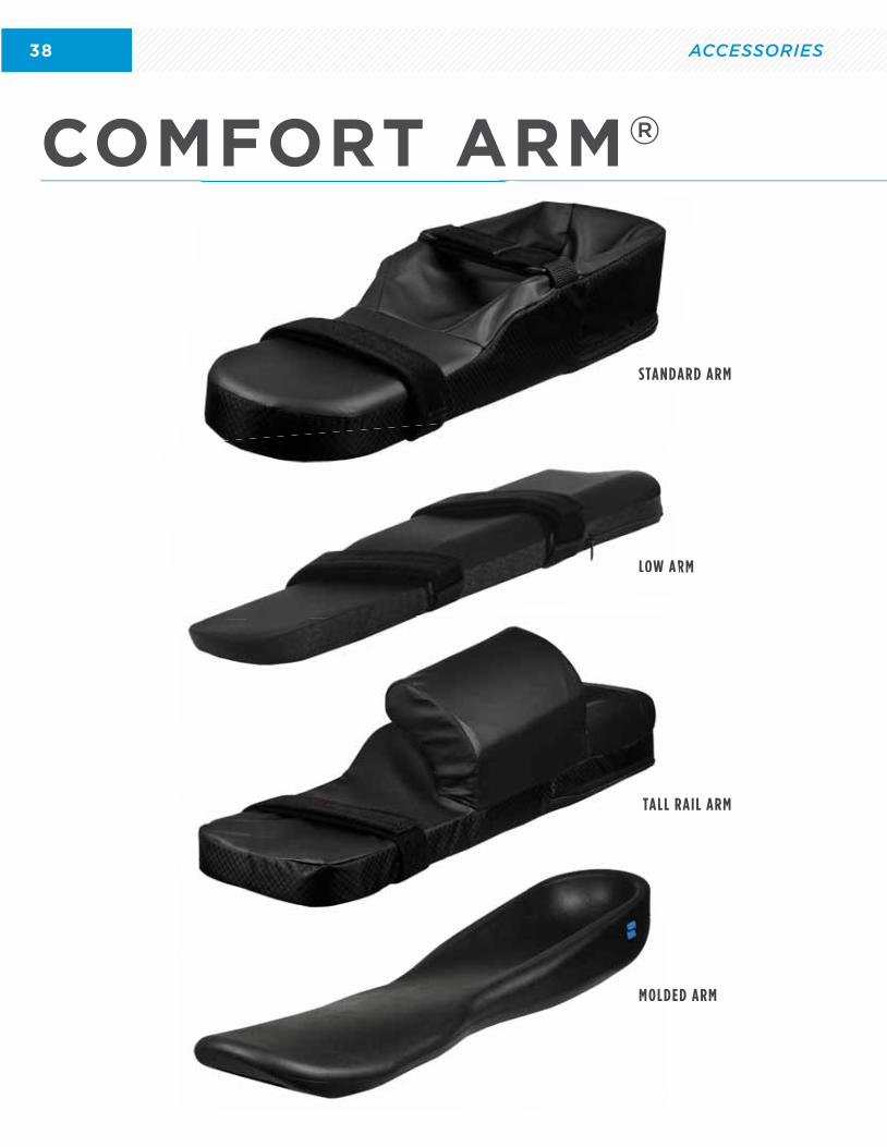
LOW ARM
MOLDED ARM
TALL RAIL ARM
STANDARD ARM
MOLD
STANDA
LOW AR
COMFORT ARM®
TALL
39
COMFORT ARM SUPPORTS
COMFORT ARM HARDWARE
MOLDED ARM
• Comfort Arm design provides finger support for all users.
• Comfortable straps for securing the arm can be adjusted or removed.
• Provides support for contractures and tone while also helping to prevent finger drop.
• Moldable option can be used to elevate fingers.
PRODUCT FEATURES
INTERLOCK BRACKETThe interlock bracket locks down to 3/4” up to 1” tubing with a two-bolt connection.
Standard with fixed or swing-away hardware option.
SWING-AWAY HARDWAREThe rotating base system allows the Comfort Arm to be angularly rotated side-to-side and adjusted front to back 7”.
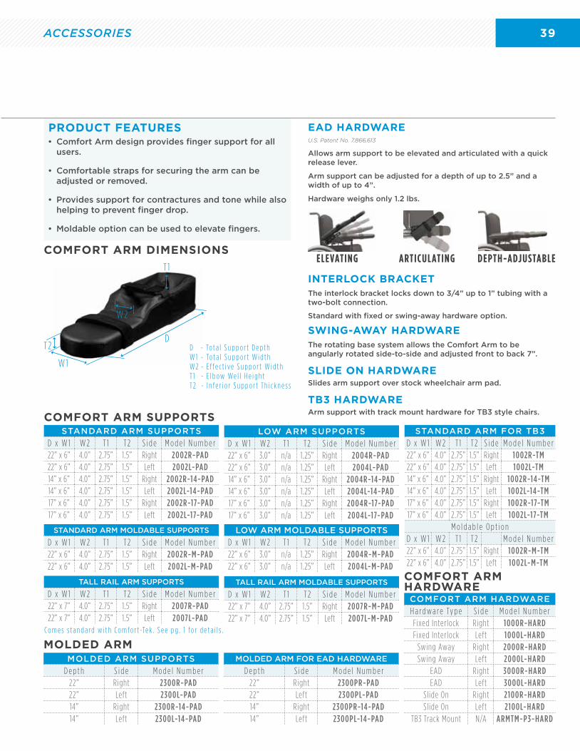
EAD HARDWAREU.S. Patent No. 7,866,613
Allows arm support to be elevated and articulated with a quick release lever.
Arm support can be adjusted for a depth of up to 2.5” and a width of up to 4”.
Hardware weighs only 1.2 lbs.
STANDARD ARM SUPPORTS
D x W 1 W 2 T 1 T 2 S i d e M o d e l N u m b e r22” x 6” 4.0” 2.75” 1.5” Right 2002R-PAD22” x 6” 4.0” 2.75” 1.5” Left 2002L-PAD14” x 6” 4.0” 2.75” 1.5” Right 2002R-14-PAD14” x 6” 4.0” 2.75” 1.5” Left 2002L-14-PAD17” x 6” 4.0” 2.75” 1.5” Right 2002R-17-PAD17” x 6” 4.0” 2.75” 1.5” Left 2002L-17-PAD
STANDARD ARM MOLDABLE SUPPORTS
D x W 1 W 2 T 1 T 2 S i d e M o d e l N u m b e r22” x 6” 4.0” 2.75” 1.5” Right 2002R-M-PAD22” x 6” 4.0” 2.75” 1.5” Left 2002L-M-PAD
TALL RAIL ARM SUPPORTS
D x W 1 W 2 T 1 T 2 S i d e M o d e l N u m b e r22” x 7” 4.0” 2.75” 1.5” Right 2007R-PAD22” x 7” 4.0” 2.75” 1.5” Left 2007L-PAD
TALL RAIL ARM MOLDABLE SUPPORTS
D x W 1 W 2 T 1 T 2 S i d e M o d e l N u m b e r22” x 7” 4.0” 2.75” 1.5” Right 2007R-M-PAD22” x 7” 4.0” 2.75” 1.5” Left 2007L-M-PAD
LOW ARM MOLDABLE SUPPORTS
D x W 1 W 2 T 1 T 2 S i d e M o d e l N u m b e r22” x 6” 3.0” n/a 1.25” Right 2004R-M-PAD22” x 6” 3.0” n/a 1.25” Left 2004L-M-PAD
LOW ARM SUPPORTS
D x W 1 W 2 T 1 T 2 S i d e M o d e l N u m b e r22” x 6” 3.0” n/a 1.25” Right 2004R-PAD22” x 6” 3.0” n/a 1.25” Left 2004L-PAD14” x 6” 3.0” n/a 1.25” Right 2004R-14-PAD14” x 6” 3.0” n/a 1.25” Left 2004L-14-PAD17” x 6” 3.0” n/a 1.25” Right 2004R-17-PAD17” x 6” 3.0” n/a 1.25” Left 2004L-17-PAD
COMFORT ARM HARDWARE
H a rd w a re Ty p e S i d e M o d e l N u m b e rFixed Interlock Right 1000R-HARDFixed Interlock Left 1000L-HARD
Swing Away Right 2000R-HARDSwing Away Left 2000L-HARD
EAD Right 3000R-HARDEAD Left 3000L-HARD
Slide On Right 2100R-HARDSlide On Left 2100L-HARD
TB3 Track Mount N/A ARMTM-P3-HARD
MOLDED ARM SUPPORTS
D e p t h S i d e M o d e l N u m b e r22” Right 2300R-PAD22” Left 2300L-PAD14” Right 2300R-14-PAD14” Left 2300L-14-PAD
MOLDED ARM FOR EAD HARDWARE
D e p t h S i d e M o d e l N u m b e r22” Right 2300PR-PAD22” Left 2300PL-PAD14” Right 2300PR-14-PAD14” Left 2300PL-14-PAD
C o m e s s t a n d a rd w i t h C o m f o r t -Te k . S e e p g . 1 f o r d e t a i l s .
TB3 HARDWAREArm support with track mount hardware for TB3 style chairs.
SLIDE ON HARDWARESlides arm support over stock wheelchair arm pad.
ELEVATING ARTICULATING DEPTH-ADJUSTABLE
STANDARD ARM FOR TB3
D x W 1 W 2 T 1 T 2 S i d e M o d e l N u m b e r22” x 6” 4.0” 2.75” 1.5” Right 1002R-TM22” x 6” 4.0” 2.75” 1.5” Left 1002L-TM14” x 6” 4.0” 2.75” 1.5” Right 1002R-14-TM14” x 6” 4.0” 2.75” 1.5” Left 1002L-14-TM17” x 6” 4.0” 2.75” 1.5” Right 1002R-17-TM17” x 6” 4.0” 2.75” 1.5” Left 1002L-17-TM
M o l d a b l e O p t i o nD x W 1 W 2 T 1 T 2 M o d e l N u m b e r22” x 6” 4.0” 2.75” 1.5” Right 1002R-M-TM22” x 6” 4.0” 2.75” 1.5” Left 1002L-M-TM
D
W 1
W 2
T 1
T 2 D - To t a l S u p p o r t D e p t hW 1 - To t a l S u p p o r t W i d t hW 2 - E f f e c t i ve S u p p o r t W i d t hT 1 - E l b ow We l l H e i g h tT 2 - I n f e r i o r S u p p o r t T h i c k n e s s
COMFORT ARM DIMENSIONS
ACCESSORIES
40
NOTES


PERMOBIL CANADA
P: 800.265.9830
F: 877.636.8944
www.permobil.ca
REHABCAT-CANADA